Manual Addendum - Support.Fluke.comsupport.fluke.com/Raytek-Sales/Download/Asset/... · Manual...
22
RAYMAPB Power Supply and Terminal Box for Marathon MM/MR/FA/FR Sensors Manual Addendum Rev. A 06/2014 51001
Transcript of Manual Addendum - Support.Fluke.comsupport.fluke.com/Raytek-Sales/Download/Asset/... · Manual...

RAYMAPB Power Supply and Terminal Box
for Marathon MM/MR/FA/FR Sensors
Manual Addendum
Rev. A 06/2014 51001


Contacts
Worldwide Headquarters Santa Cruz, CA USA Tel: +1 800 227 – 8074 (USA and Canada only) +1 831 458 – 3900 Fax: +1 831 458 – 1239 [email protected]
European Headquarters Berlin, Germany Tel: +49 30 4 78 00 80 [email protected]
France [email protected]
United Kingdom [email protected]
Fluke Service Center Beijing, China Tel: +86 10 6438 4691 Tel: +86 10 4008103435 (Service) [email protected]
Internet: http://www.raytek.com/
Thank you for purchasing this Raytek product. Register today at www.raytek.com/register to receive the latest updates, enhancements and software upgrades!
This document is part of the operating instructions for the Marathon MM/MR/FA/FR Series. All tips and notices regarding acceptable operation and safety must be read in addition to the manual addendum.
© Raytek Corporation Raytek and the Raytek Logo are registered trademarks of Raytek Corporation. All rights reserved. Specifications subject to change without notice.

Warranty
The manufacturer warrants this instrument to be free from defects in material and workmanship under normal use and service for the period of one year from date of purchase. This warranty extends only to the original purchaser. This warranty shall not apply to fuses, batteries, or any product which has been subject to misuse, neglect, accident, or abnormal conditions of operation.
In the event of failure of a product covered by this warranty, the manufacturer will repair the instrument when it is returned by the purchaser, freight prepaid, to an authorized Service Facility within the applicable warranty period, provided manufacturer’s examination discloses to its satisfaction that the product was defective. The manufacturer may, at its option, replace the product in lieu of repair. With regard to any covered product returned within the applicable warranty period, repairs or replacement will be made without charge and with return freight paid by the manufacturer, unless the failure was caused by misuse, neglect, accident, or abnormal conditions of operation or storage, in which case repairs will be billed at a reasonable cost. In such a case, an estimate will be submitted before work is started, if requested.
THE FOREGOING WARRANTY IS IN LIEU OF ALL OTHER WARRANTIES, EXPRESSED OR IMPLIED, INCLUDING BUT NOT LIMITED TO ANY IMPLIED WARRANTY OF MERCHANTABILITY, FITNESS, OR ADEQUACY FOR ANY PARTICULAR PURPOSE OR USE. THE MANUFACTURER SHALL NOT BE LIABLE FOR ANY SPECIAL, INCIDENTAL OR CONSEQUENTIAL DAMAGES, WHETHER IN CONTRACT, TORT, OR OTHERWISE.
Specifications subject to change without notice.

Content CONTENT .......................................................................................................................................................... III
1 SAFETY INSTRUCTIONS .............................................................................................................................. 4
2 PRODUCT DESCRIPTION ............................................................................................................................ 7
3 TECHNICAL DATA ......................................................................................................................................... 9 3.1 Electrical Specifications ................................................................................................................................ 9 3.2 Environmental Specifications ....................................................................................................................... 9 3.3 Dimensions.................................................................................................................................................. 10 3.4 Scope of Delivery ........................................................................................................................................ 10
4 INSTALLATION ............................................................................................................................................ 11 4.1 Mounting the RAYMAPB Terminal Box ................................................................................................... 11 4.2 AC Power and Earth Ground Connections .................................................................................................. 11 4.3 Connecting the AC Power and Ground Wires ............................................................................................ 13 4.4 Sensor Interconnecting Cable Preparation .................................................................................................. 14
4.4.1 Cable Preparation ................................................................................................................................ 14 4.4.2 Cable Ports and Cable Glands ............................................................................................................. 14
4.5 Sensor Interconnecting Cable Installation ................................................................................................... 15 4.6 Connecting Device Cables to RAYMAPB ................................................................................................. 16
4.6.1 Recommended Cable Types ................................................................................................................. 16 4.6.2 Grounding and Shielding .................................................................................................................... 17 4.6.3 System Connections ............................................................................................................................ 18 4.6.4 RS-485 Digital Communications ........................................................................................................ 18 4.6.5 Analog Output .................................................................................................................................... 19 4.6.6 Relay Output....................................................................................................................................... 19 4.6.7 Trigger ................................................................................................................................................. 19
5 MAINTENANCE ............................................................................................................................................ 20 5.1 Cleaning the RAYMAPB ............................................................................................................................ 20 5.2 Service ......................................................................................................................................................... 20

Safety Instructions
4 Rev. A 06/2014 RAYMAPB
1 Safety Instructions This document contains important information, which should be kept at all times with the instrument during its operational life. Other users of this instrument should be given these instructions with the instrument. Eventual updates to this information must be added to the original document. The instrument can only be operated by trained personnel in accordance with these instructions and local safety regulations.
All safety related regulations, local codes and instructions that appear in this literature or on equipment must be observed to ensure personal safety and to prevent damage to either the instrument or equipment connected to it. If equipment is used in a manner not specified by the manufacturer, the protection provided by the equipment may be impaired.
Acceptable Operation This instrument is intended only for processing of measurement values. The instrument is appropriate for continuous use. The instrument operates reliably in demanding conditions, such as in high environmental temperatures, as long as the documented technical specifications for all instrument components are adhered to. Compliance with the operating instructions is necessary to ensure the expected results. Unacceptable Operation The instrument should not be used for medical diagnosis. Do not use this unit to directly command motors, valves, or other actuators not equipped with safeguards. To do so can be potentially harmful to persons or equipment in the event of a fault to the unit. Replacement Parts and Accessories Use only original parts and accessories approved by the manufacturer. The use of other products can compromise the operation safety and functionality of the instrument.

Safety Instructions
RAYMAPB Rev. A 06/2014 5
Safety Symbols
AC (Alternating Current)
DC (Direct Current)
Risk of danger. Important information. See manual.
Hazardous voltage. Risk of electrical shock.
Helpful information regarding the optimal use of the instrument.
Earth (ground)
Protective earth (ground)
DC power supply
Switch or relay contact
CAT II
Measurement Category II is applicable to test and measuring circuits connected directly to utilization points (socket outlets and similar points) of the low–voltage MAINS installation.
Conforms to European Union directive.
Disposal of old instruments should be handled according to professional and environmental regulations as electronic waste.

Safety Instructions
6 Rev. A 06/2014 RAYMAPB
Warning To prevent possible electrical shock, fire, or personal injury follow these guidelines:
• Read all safety Information before you use the product. • Use the product only as specified, or the protection supplied by the product can be
compromised. • Carefully read all instructions. • Do not use and disable the product if it is damaged. • Do not use the product if it operates incorrectly. • Make sure the ground conductor in the mains power cord is connected to a protective earth
ground. Disruption of the protective earth could put voltage on the chassis that could cause death.
• Replace the mains power cord if the insulation is damaged or if the insulation shows signs of wear.

Product Description
RAYMAPB Rev. A 06/2014 7
2 Product Description The RAYMAPB terminal box accessory is a steel junction box with a continuous hinge and clamps designed to provide IP65 (NEMA-4) protection to a terminal block for sensor wiring and a power supply for power (24 VDC) to a sensor. The terminal box is also provided with three cable ports for accessing the input and outputs of the sensor with customer wiring. The box can be surface mounted using the flanges and holes provided on the RAYMAPB. The ambient operating temperatures should be kept within the range of 0 to 50°C (32 to 120°F) for the terminal box.
Figure 1: RAYMAPB Terminal Box
There are three 21.1 mm (0.83 inch) cable ports on the RAYMAPB for use with cable glands or conduit. Two cable ports are on the bottom of the RAYMAPB these can be used for the sensor interconnecting cable and for input/output wiring. On the right side of the enclosure one cable port is provided for AC power wiring nearest the power supply. A three wire AC power cable or individual discrete wires may be used. A system overview of the RAYMAPB is shown on Figure 2.
To maintain the IP65 (NEMA 4) rating, the three cable ports on the enclosure must be closed with cable glands and properly sized cables or sealing hole plugs that are IP65 (NEMA 4) rated. Do not leave any cable port empty.
The hole covers shipped with the RAYMAPB are for shipping purposes only and are NOT IP65 rated.

Product Description
8 Rev. A 06/2014 RAYMAPB
Figure 2: RAYMAPB System Overview
Sensor
100 to 240 VAC 50/60 Hz
4-20 mA
0-20 mA
Analog Meter
Digital Indicator
Recorder
PLC Sensor Alarm
• External adjustable emissivity • Hold reset • Laser On/Off • Background Temperature
Compensation
Sensor Cable
0 to 5 VDC
Target

Technical Data
RAYMAPB Rev. A 06/2014 9
3 Technical Data 3.1 Electrical Specifications
AC Power input 100 to 240 VAC, 50/60 Hz, 0.6 A external fuse: 1.5 A slow blow type (not supplied)
DC Power output 24 VDC, 1.1 A
3.2 Environmental Specifications
Ingress Protection IEC 60529: IP65 (NEMA 4)
Operating Ambient Temperature 0 to 50°C (32 to 122°F)
Storage Temperature -20 to 60°C (-4 to 140°F)
Construction Steel / Aluminum
EM Environment IEC 61326: Industrial
Protection Class I
Safety IEC 61010-1: 300 V CATII, Pollution Degree 2
Altitude up to 2000 m (6562 ft)

Technical Data
10 Rev. A 06/2014 RAYMAPB
3.3 Dimensions
Figure 3: RAYMAPB Terminal Box Dimensions
3.4 Scope of Delivery The scope of delivery includes the following:
• RAYMAPB terminal box • Temporary hole plugs • Safety sheet
Installation
RAYMAPB Rev. A 06/2014 11
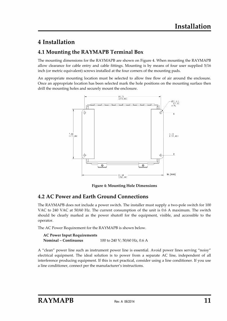
4 Installation 4.1 Mounting the RAYMAPB Terminal Box The mounting dimensions for the RAYMAPB are shown on Figure 4. When mounting the RAYMAPB allow clearance for cable entry and cable fittings. Mounting is by means of four user supplied 5/16 inch (or metric equivalent) screws installed at the four corners of the mounting pads.
An appropriate mounting location must be selected to allow free flow of air around the enclosure. Once an appropriate location has been selected mark the hole positions on the mounting surface then drill the mounting holes and securely mount the enclosure.
Figure 4: Mounting Hole Dimensions
4.2 AC Power and Earth Ground Connections The RAYMAPB does not include a power switch. The installer must supply a two-pole switch for 100 VAC to 240 VAC at 50/60 Hz. The current consumption of the unit is 0.6 A maximum. The switch should be clearly marked as the power shutoff for the equipment, visible, and accessible to the operator.
The AC Power Requirement for the RAYMAPB is shown below.
AC Power Input Requirements Nominal – Continuous 100 to 240 V; 50/60 Hz, 0.6 A
A “clean” power line such as instrument power line is essential. Avoid power lines serving “noisy” electrical equipment. The ideal solution is to power from a separate AC line, independent of all interference producing equipment. If this is not practical, consider using a line conditioner. If you use a line conditioner, connect per the manufacturer’s instructions.

Installation
12 Rev. A 06/2014 RAYMAPB
Improper installation can result in serious injury or death to personnel! The RAYMAPB was designed to meet IEC 61010-1: Safety Requirements for Electrical Equipment for Measurement. The installation should be performed as directed in this manual and following any local electrical codes.
Follow all local electrical codes related to installation and grounding of electrical equipment.
Compliance with IEC 61010-1: Safety Requirements for Electrical Equipment for Measurement requires the installation meet the following alternating current supply and earth grounding requirements.
The installation should be compliant with requirements for a Category II installation.
A three-wire AC supply with a third-wire earth ground or a separate earth ground wire is required.
Power cables and wires should meet recognized European and American standards for Main Voltage Safety with insulation suitable for single fault condition (600V, 105°C/221°F).
Cable gland and compression fittings for the power cable must comply with European and American standards as dictated by the power cable selected.
The wire size for the L and N AC power connections should be no larger than 18 AWG (1 mm²). These power wires cannot be larger in diameter than the ground wire.
A ground wire must be connected to the Protective Earth terminal. The ground wire must be 18 AWG or equivalent per IEC 61010-1.
A two-pole power shutoff or safety switch should be incorporated within the main power line that powers the Raytek equipment. This switch should be in close proximity to the operator. The switch should be clearly marked as the power shutoff for the equipment.
A properly sized circuit breaker is required in the AC supply lines connecting power to the Power Supply.
The two-pole switch (and all circuit breakers) should comply with IEC 60947 standard. Switches and circuit breakers that carry the markings of TÜV, VDE or other European Agencies do meet the IEC 60947 standard.

Installation
RAYMAPB Rev. A 06/2014 13
4.3 Connecting the AC Power and Ground Wires Use tinned stranded 18 AWG (1 mm²) or equivalent wire for all AC power and ground connections. Strip insulation from wires 1/4 inch (8 mm).
To prevent personal injury, make sure the Mains disconnect switch is off before removing lid.
To access the power wiring and ground terminals, carefully unscrew the four screws and clamps that secure the lid onto the enclosure. Leave the red and black wires connected to the power supply; these wires are for the 24 VDC power to the terminal strip for the sensor.
Figure 5: AC Power Wiring Detail
Remove the shipping hole plug from the cable port on the right side of the RAYMAPB, the right side of the enclosure is the side with only one cable port. Then install customer supplied cable gland and pass AC cable though cable gland. Next connect the LINE and NEUTRAL wires of the AC power line to the Power Supply inside the RAYMAPB box. Observe the “polarity” of these connections, LINE to AC (L) and NEUTRAL to AC (N), as indicated on the power supply. The Power supply module Ground connection is pre-wired at the factory. Do not remove this wire.
You must provide a Protective Earth by connecting a ground wire to the threaded grounding stud on the mounting plate inside the RAYMAPB exactly as shown in the Ground Wire Detail Drawing and illustration shown in Figure 6. Disassemble the ground stud assembly; crimp the earth ground wire to Item 5. Reassemble the stud assembly exactly as shown making sure that the Protective Earth connection is installed first and makes direct contact with the mounting plate. Make sure all hardware is tightly fastened in each step of the reassembly.
To prevent possible electrical shock, fire or personal injuries make sure that the RAYMAPB is grounded before use.

Installation
14 Rev. A 06/2014 RAYMAPB
All parts supplied assembled in box.
Item 1: Threaded Ground Stud, 10-32 UNF Item 2: Quantity 2, Hex Nut 10-32 UNF Item 3: Quantity 2, External Star Washer #10 Item 4: Terminal Lug, #10 Ring, with power supply ground wire attached Item 5: Terminal Lug, #10 Ring Lug, 14-18 AWG for customer supplied Protective Earth wire
Figure 6: Ground Wire Detail
Figure 7: Earth Ground Connection
4.4 Sensor Interconnecting Cable Preparation 4.4.1 Cable Preparation It is very important that the cable shield be properly prepared and installed. All signal cable shielding must be grounded to the RAYMAPB enclosure with customer supplied Grounding Cable Glands.
Customer supplied grounding cable glands must also be rated for minimum IP65 ingress protection (IEC 60529) in order to maintain enclosure rating.
All cables must be properly dressed for shield grounding. Twisted pair wires must remain twisted and kept as short as possible. The sensor cable is supplied with the connector attached on one end and the opposite wiring end of the cable is prepared with connector terminals for easy installation.
4.4.2 Cable Ports and Cable Glands
Three cable ports are provided for routing the various signal and power cables. The ports accept 1/2 inch NPT cable glands or conduit. All cables routed to the RAYMAPB must be routed through sealed cable gland fittings or conduit. The hole plugs shipped with the RAYMAPB are for shipping purposes only, they do not provide IP65 sealing. All cable ports must have cable glands, conduit, or sealing hole plugs installed to maintain enclosure rating.
Item 5

Installation
RAYMAPB Rev. A 06/2014 15
Customer supplied cable glands must have a cable diameter range that match the cables used. Use properly sized cable glands, do not attempt to improvise by making the cable thicker to fit cable gland.
Grounding cable glands are required for the sensor cable and for sensor input/output wiring. Grounding cable glands should ground shielding cable to RAYMAPB enclosure. Follow manufactures specifications for proper installation and cable preparation for customer supplied grounding cable glands. The AC mains power cable does not need grounding cable glands.
To maintain IEC 61326 compliance the Sensor, mA Output, Trigger Input, and Sensor Relay cable shields must be connected to grounding cable glands.
4.5 Sensor Interconnecting Cable Installation
For safety of personnel, AC power should not be applied to the RAYMAPB when the lid is removed. Disconnect power during wiring of the unit.
Remove the shipping hole plug from cable port and install customer supplied grounding cable gland following manufactures instructions. Insert the interconnecting cable into the cable gland and route all wires to their corresponding terminals identified by wire color. Insert the wires into the corresponding terminal on the terminal block and tighten.
Figure 8: RAYMAPB Terminal Block

Installation
16 Rev. A 06/2014 RAYMAPB
4.6 Connecting Device Cables to RAYMAPB 4.6.1 Recommended Cable Types
To maintain signal integrity and reduce noise pick-up, twisted pair shielded cables with braid shielding should be used for connecting to all Sensor inputs and outputs. Belden low capacitance computer cable types 9829, 9830, 9831, 9832, 9839 and 9833, or equivalent cables are recommended. Each of these cables has a different number of wire pairs varying in quantity from 2 to 7 pairs.
The cable selected should have a twisted pair nominal impedance of 100 Ω and nominal capacitance between conductors should not exceed 15.5 pF/ft (50.9 pF/m).
All user-supplied cables should be grounded to the RAYMAPB with customer supplied grounding cable glands. Select cable glands that match the cable diameters of cable to be used.

Installation
RAYMAPB Rev. A 06/2014 17
4.6.2 Grounding and Shielding
Follow all grounding and shielding instructions provided below. Proper connection of the cable shields is important to avoid noise and ground loop problems that may cause errors. The use of Grounding Cable Glands connects the cable shield to ground at the RAYMAPB.
Prior to making any wiring changes ensure that AC power is off!
Figure 9: RAYMAPB Wiring Notes:
1. This symbol designates a Protective Earth terminal. 2. If you use a line conditioner or isolation transformer, connect per manufacturer’s instructions.
Observe grounding instructions and make sure earth ground is supplied to Ground terminal. 3. If the mounting surface of the Sensor is not at earth ground potential you must insulate the
Sensor from surface as shown in the Figure above. The Sensor is connected to RAYMAPB enclosure by the Sensor Cable shield.

Installation
18 Rev. A 06/2014 RAYMAPB
4.6.3 System Connections
Refer to Raytek sensor manual for further Operation Information.
Pin Cable Color Description
A black RxA*
B white RxB*
C gray TxB**
D purple TxA**
E white/drain Shield
F yellow Trigger / External Input
G orange Relay COM
H blue Relay NO/NC
J green + mA out
K brown - mA out (analog ground)
L black Digital ground
M red +24 VDC
* RxA and RxB are twisted paired
** TxA and TxB are twisted paired
Table 1: Sensor Interconnecting Cable / Function
4.6.4 RS-485 Digital Communications
Connections for RS485 communications are made on the terminal block for RxA, RxB, TxA, and TxB. For maximum cable length and detailed wiring refer to Raytek sensor manual.

Installation
RAYMAPB Rev. A 06/2014 19
4.6.5 Analog Output
The analog output is a current loop temperature signal from 4 to 20 mADC or 0 to 20 mADC, user selectable, linear with measured temperature. The corresponding temperature span is adjustable. Temperature signal connections are made to the + mA and –mA terminals. The analog output provides a mA signal directly connectable to a recording device (e.g., chart recorder), PLC, or controller.
Figure 10: Wiring to the Terminal Block
4.6.6 Relay Output The relay output can be used as an alarm for failsafe conditions or as a setpoint relay, refer to Raytek sensor manual for further details. The relay output can be used to indicate an alarm state or to control external actions. The relay can be set to either NO (Normally Open) or NC (Normally Closed) with a RS485 command.
4.6.7 Trigger
The Trigger input can be used to provide certain functions (e.g. resetting, remote emissivity setting, etc.) depending on the sensor series being, see Raytek sensor manual for further details.
Shield
to Sensor

Maintenance
20 Rev. A 06/2014 RAYMAPB
5 Maintenance The following sections provide the information necessary for the user to perform basic maintenance. Users should not attempt to perform maintenance not described in this section.
Warning
To prevent possible electrical shock, fire or personal injury follows these guidelines: • Do not operate the product with lid removed. Hazardous voltage exposure is possible. • Make sure the power cord is removed and mains disconnect switch is off before removing
cover. • Use only specified replacement parts. • Use only specified replacement fuses. • Have an approved technician repair the product.
5.1 Cleaning the RAYMAPB If the instrument requires cleaning, wipe it down with a soft cloth that is lightly dampened with water or a mild detergent. Do not use abrasives or solvents.
5.2 Service The RAYMAPB does not have any user serviceable components. If it fails to operate correctly contact Raytek service.