Manual 750-662/000-003 - Safety Control · WAGO-I/O-SYSTEM 750 Table of Contents 5 750-662/000-003...
134
Pos: 2 /Dokumentation allgemein/Einband/Einband Handbuch - Frontseite 2015 - mit DocVariablen (Standard) @ 9\mod_1285229289866_0.docx @ 64941 @ @ 1 WAGO-I/O-SYSTEM 750 Manual 750-662/000-003 8FDI 24V PROFIsafe V2 iPar 8-Channel Digital Input Safety Module PROFIsafe V2 iPar Version 1.5.0, valid from HW/SW Version 01/02 Pos: 3 /Alle Serien (Allgemeine Module)/Hinweise zur Dokumentation/Impressum für Standardhandbücher - allg. Angaben, Anschriften, Telefonnummern und E-Mail-Adressen @ 3\mod_1219151118203_21.docx @ 21060 @ @ 1
Transcript of Manual 750-662/000-003 - Safety Control · WAGO-I/O-SYSTEM 750 Table of Contents 5 750-662/000-003...

Pos: 2 /Dokumentation allgemein/Einband/Einband Handbuch - Frontseite 2015 - mit DocVariablen (Standard) @ 9\mod_1285229289866_0.docx @ 64941 @ @ 1
WAGO-I/O-SYSTEM 750 Manual
750-662/000-003 8FDI 24V PROFIsafe V2 iPar
8-Channel Digital Input Safety Module PROFIsafe V2 iPar
Version 1.5.0, valid from
HW/SW Version 01/02
Pos: 3 /Alle Serien (Allgemeine Module)/Hinweise zur Dokumentation/Impressum für Standardhandbücher - allg. Angaben, Anschriften, Telefonnummern und E-Mail-Adressen @ 3\mod_1219151118203_21.docx @ 21060 @ @ 1

2 WAGO-I/O-SYSTEM 750 750-662/000-003 8FDI 24V PROFIsafe V2 iPar
Manual Version 1.5.0, valid from HW/SW Version 01/02
© 2015 by WAGO Kontakttechnik GmbH & Co. KG All rights reserved.
WAGO Kontakttechnik GmbH & Co. KG
Hansastraße 27 D-32423 Minden
Phone: +49 (0) 571/8 87 – 0 Fax: +49 (0) 571/8 87 – 1 69
E-Mail: [email protected]
Web: http://www.wago.com
Technical Support
Phone: +49 (0) 571/8 87 – 5 55 Fax: +49 (0) 571/8 87 – 85 55
E-Mail: [email protected]
Every conceivable measure has been taken to ensure the accuracy and completeness of this documentation. However, as errors can never be fully excluded, we always appreciate any information or suggestions for improving the documentation.
E-Mail: [email protected]
We wish to point out that the software and hardware terms as well as the trademarks of companies used and/or mentioned in the present manual are generally protected by trademark or patent.
=== Ende der Liste für Textmarke Einband_vorne ===

WAGO-I/O-SYSTEM 750 Table of Contents 3 750-662/000-003 8FDI 24V PROFIsafe V2 iPar
Manual Version 1.5.0, valid from HW/SW Version 01/02
Pos: 5 /Dokumentation allgemein/Verzeichnisse/Inhaltsverzeichnis - Überschrift oG und Verzeichnis @ 3\mod_1219151230875_21.docx @ 21063 @ @ 1
Table of Contents 1 Notes about this Documentation ................................................................. 7 1.1 Validity of this Documentation ................................................................. 7 1.2 Copyright ................................................................................................... 8 1.3 Symbols ..................................................................................................... 9 1.4 Number Notation ..................................................................................... 11 1.5 Font Conventions .................................................................................... 11
2 Important Notes ......................................................................................... 12 2.1 Legal Bases ............................................................................................. 12 2.1.1 Subject to Changes ............................................................................. 12 2.1.2 Personnel Qualifications ..................................................................... 12 2.1.3 Use of the WAGO-I/O-SYSTEM 750 in
Compliance with Underlying Provisions ............................................ 12 2.1.4 Technical Condition of Specified Devices ......................................... 13 2.2 Safety Advice (Precautions) .................................................................... 14
3 PROFIsafe .................................................................................................. 16 3.1 iPar Server ............................................................................................... 18
4 Device Description ..................................................................................... 20 4.1 View ........................................................................................................ 22 4.2 Connectors ............................................................................................... 23 4.2.1 Data Contacts/Internal Bus ................................................................. 23 4.2.2 Power Jumper Contacts/Field Supply ................................................ 24 4.2.3 CAGE CLAMP® Connectors ............................................................. 26 4.3 Display Elements .................................................................................... 27 4.4 Operating Elements ................................................................................. 31 4.5 Schematic Diagrams ................................................................................ 32 4.5.1 Input Block Diagram .......................................................................... 32 4.6 Technical Data ........................................................................................ 33 4.6.1 Device Data ........................................................................................ 33 4.6.2 Power Supply...................................................................................... 33 4.6.3 Communication .................................................................................. 34 4.6.4 Digital Inputs ...................................................................................... 35 4.6.5 Digital Clock Outputs ......................................................................... 36 4.6.6 Safety Parameters ............................................................................... 37 4.6.6.1 Two-channel Safety Application,
Proof Test Interval 10 Years .......................................................... 37 4.6.6.2 Two-channel Safety Application,
Proof Test Interval 20 Years .......................................................... 38 4.6.6.3 Single-channel Safety Application,
Proof Test Interval 10 Years .......................................................... 39 4.6.6.4 Single-channel Safety Application,
Proof Test Interval 20 Years .......................................................... 40 4.6.7 Connection Type ................................................................................ 41 4.6.8 Climatic Environmental Conditions ................................................... 41 4.6.9 Response Times .................................................................................. 42
4 Table of Contents WAGO-I/O-SYSTEM 750 750-662/000-003 8FDI 24V PROFIsafe V2 iPar
Manual Version 1.5.0, valid from HW/SW Version 01/02
4.6.9.1 Safe Response Time of Digital Inputs in the Event of a Failure ................................................................. 42
4.6.9.2 Typical Response Time of the Digital Inputs in an Error-free Case ...................................................................... 44
4.7 Approvals ................................................................................................ 45 4.8 Standards and Guidelines ........................................................................ 47 4.8.1 Transport and Storage Conditions ...................................................... 48
5 Process Image ............................................................................................. 49 5.1 PROFIsafe V1 Mode ............................................................................... 49 5.2 PROFIsafe V2 Mode ............................................................................... 50
6 Mounting ..................................................................................................... 51 6.1 Mounting Sequence ................................................................................. 51 6.2 Inserting and Removing Devices ............................................................ 52 6.2.1 Inserting the I/O Module .................................................................... 52 6.2.2 Removing the I/O Module .................................................................. 53
7 Connect Devices ......................................................................................... 54 7.1 Connecting a Conductor to the CAGE CLAMP® ................................... 54 7.2 Power Supply Concept ............................................................................ 55 7.2.1 Using a Backup Capaciter in Case of Interruptions
in the Power Supply............................................................................ 57 7.2.2 Using 230V AC I/O Modules ............................................................. 58 7.2.2.1 230V AC Modules are Used in Another Fieldbus
Node that Contains no PROFIsafe I/O Modules ........................... 58 7.2.2.2 230V AC I/O Modules and PROFIsafe I/O Modules
are Used Together in one Fieldbus Node ...................................... 58 7.3 Connection Examples .............................................................................. 59 7.3.1 Connection Examples for Digital Inputs in the "Standard"
Operating Mode .................................................................................. 59 7.3.1.1 Emergency Off Connection, Single-channel ................................. 60 7.3.1.2 Emergency Off Connection, Dual channel,
Equivalent Evaluation .................................................................... 62 7.3.1.3 Protective Door Monitoring Connection, Dual Channel,
Antivalent Evaluation .................................................................... 64 7.3.2 Connection Example for Digital Inputs in Rotary Table
Operating Mode .................................................................................. 65
8 Commissioning ........................................................................................... 67 8.1 Startup and Maintenance Instructions ..................................................... 67 8.1.1 Proof Test Interval/Usage Duration .................................................... 67 8.1.2 Adding or Replacing Components ..................................................... 68 8.2 Setting the PROFIsafe Address ............................................................... 68 8.2.1 Setting the PROFIsafe Address using the Coding Switch .................. 69 8.2.2 Setting the PROFIsafe Address using the
WAGO Parameterization Tool ........................................................... 69 8.3 Parameterization of the PROFIsafe I/O Module with the
WAGO Parameterization Tool ................................................................ 70 8.3.1 ONLINE Mode ................................................................................... 70 8.3.2 OFFLINE Mode ................................................................................. 73 8.3.3 Description of the Call Options .......................................................... 74
WAGO-I/O-SYSTEM 750 Table of Contents 5 750-662/000-003 8FDI 24V PROFIsafe V2 iPar
Manual Version 1.5.0, valid from HW/SW Version 01/02
8.3.3.1 Indirect Start via WAGO-I/O-CHECK from the Operating System ........................................................................... 74
8.3.3.2 Direct Start from the Operating System ........................................ 75 8.3.3.3 Indirect Start via WAGO-I/O-CHECK from
the Configuration Program (Device Level TCI Conformance Class 2) .................................... 75
8.3.3.4 Indirect Start via WAGO-I/O-CHECK from the Configuration Program (Module Level TCI Conformance Class 2) ................................... 75
8.3.3.5 Direct Start from the Configuration Program (Device Level TCI Conformance Class 3) .................................... 75
8.3.3.6 Direct Start from the Configuration Program (Module Level TCI Conformance Class 3) ................................... 76
8.3.3.7 Direct Start from the Configuration Program (Device Level TCI Conformance Class 3 OFFLINE) ................... 76
8.3.3.8 Direct Start from the Configuration Program (Module Level TCI Conformance Class 3 OFFLINE) .................. 76
8.3.4 Adjustable Parameters ........................................................................ 77 8.3.4.1 Parameter Input Filter Time ........................................................... 78 8.3.4.2 Short circuit Test Ix Parameter ...................................................... 79 8.3.4.3 Parameter Dual Channel Evaluation Ix & Ix+1 ............................. 81 8.3.4.4 Parameter Discrepancy Time Ix & Ix+1 ........................................ 82 8.3.4.5 Parameter Valance Evaluation Ix & Ix+1 ...................................... 85 8.3.4.6 Parameter Restart Inhibit Ix & Ix+1 .............................................. 87 8.3.4.7 Parameter Operating Mode ............................................................ 88 8.4 Programming the Safe PLC .................................................................... 89 8.4.1 PROFIsafe I/O Module without iPar Functionality ............................ 90 8.4.2 PROFIsafe I/O Module with iPar Functionality and iPar Server ....... 90 8.4.3 PROFIsafe I/O Module with iPar Functionality without iPar Server . 91
9 Diagnostics .................................................................................................. 93 9.1 Behavior in the Event of an Error ........................................................... 93 9.2 Diagnosis of Errors ................................................................................. 94 9.3 Acknowledging Error Messages ........................................................... 100 9.3.1 Variant 1: User Acknowledgement via “OA_Req” .......................... 101 9.3.2 Variant 2: User Acknowledgement via “OA_Req” and “F_Ack” ... 102
10 Service ....................................................................................................... 103 10.1 Replacing a PROFIsafe I/O Module ..................................................... 103 10.1.1 Procedure .......................................................................................... 103 10.1.2 I/O Module with iPar Server Functionality ...................................... 104 10.1.2.1 PROFIsafe Address Set Using the Coding Switch ...................... 104 10.1.2.2 PROFIsafe Address Set Using the Parameterization Tool .......... 104 10.1.3 I/O Module without iPar Server Functionality ................................. 104 10.1.3.1 PROFIsafe Address Set Using the Coding Switch ...................... 104 10.1.3.2 PROFIsafe Address Set Using the Parameterization Tool .......... 105
11 Use in Hazardous Environments ............................................................ 106 11.1 Marking Configuration Examples ......................................................... 107 11.1.1 Marking for Europe According to ATEX and IEC-Ex .................... 107 11.1.2 Marking for America According to NEC 500 .................................. 112
6 Table of Contents WAGO-I/O-SYSTEM 750 750-662/000-003 8FDI 24V PROFIsafe V2 iPar
Manual Version 1.5.0, valid from HW/SW Version 01/02
11.2 Installation Regulations ......................................................................... 113 11.2.1 Special Conditions for Safe Use
(ATEX Certificate TÜV 07 ATEX 554086 X) ................................ 114 11.2.2 Special Conditions for Safe Use
(ATEX Certificate TÜV 12 ATEX 106032 X) ................................ 115 11.2.3 Special Conditions for Safe Use
(IEC-Ex Certificate TUN 09.0001 X) .............................................. 116 11.2.4 Special Conditions for Safe Use
(IEC-Ex Certificate IECEx TUN 12.0039 X) .................................. 117 11.2.5 Special Conditions for Safe Use
According to ANSI/ISA 12.12.01 .................................................... 118
12 Appendix ................................................................................................... 119 12.1 Overview of PROFIsafe F Parameters .................................................. 119 12.2 PROFIsafe Certificates .......................................................................... 123
13 Glossary .................................................................................................... 124
List of Figures .................................................................................................... 131
List of Tables ...................................................................................................... 132
=== Ende der Liste für Textmarke Verzeichnis_vorne ===

WAGO-I/O-SYSTEM 750 Notes about this Documentation 7 750-662/000-003 8FDI 24V PROFIsafe V2 iPar
Manual Version 1.5.0, valid from HW/SW Version 01/02
Pos: 7 /Alle Serien (Allgemeine Module)/Überschriften für alle Serien/Hinweise zur Dokumentation/Hinweise zu dieser Dokumentation - Überschrift 1 @ 4\mod_1237987661750_21.docx @ 29029 @ 1 @ 1
1 Notes about this Documentation Pos: 8 /Alle Serien (Allgemeine Module)/Hinweise zur Dokumentation/Hinweise/Hinweis: Dokumentation aufbewahren @ 4\mod_1237987339812_21.docx @ 29026 @ @ 1
Always retain this documentation! This documentation is part of the product. Therefore, retain the documentation during the entire service life of the product. Pass on the documentation to any subsequent user. In addition, ensure that any supplement to this documentation is included, if necessary.
Pos: 9 /Alle Serien (Allgemeine Module)/Hinweise zur Dokumentation/Hinweise/Hinweis: Glossar beachten @ 7\mod_1268743847968_21.docx @ 52603 @ @ 1
Technical Terms in this Documentation The technical terms used in this documentation are available in the glossary at the end of the manual.
Pos: 10 /Alle Serien (Allgemeine Module)/Überschriften für alle Serien/Hinweise zur Dokumentation/Gültigkeitsbereich - Überschrift 2 @ 12\mod_1338912448776_21.docx @ 96469 @ 2 @ 1
1.1 Validity of this Documentation Pos: 11 /Alle Serien (Allgemeine Module)/Hinweise zur Dokumentation/Gültigkeitsbereich Dokumentation für Produkt, ohne Variantenangabe @ 16\mod_1374744847003_21.docx @ 126980 @ @ 1
This documentation applies to: “8FDI 24V PROFIsafe V2 iPar” (750-662/000-003).
Pos: 12 /Alle Serien (Allgemeine Module)/Hinweise zur Dokumentation/Gültigkeitsbereich Dokumentation Ergänzung "ab <FW/HW/SW-Version>" @ 20\mod_1407749774742_21.docx @ 161508 @ @ 1
This documentation is only applicable from HW/SW Version 01/02. Pos: 13 /Serie 750 (WAGO-I/O-SYSTEM)/Hinweise zur Dokumentation/Hinweise/Achtung: Hinweis zur Dokumentation Busklemmen 750-xxxx @ 4\mod_1237986979656_21.docx @ 29023 @ @ 1
The I/O module 750-662/000-003 shall only be installed and operated according to the instructions in this manual and in the manual for the used fieldbus coupler/controller.
Consider power layout of the WAGO-I/O-SYSTEM 750! In addition to these operating instructions, you will also need the manual for the used fieldbus coupler/controller, which can be downloaded at www.wago.com. There, you can obtain important information including information on electrical isolation, system power and supply specifications.
Pos: 14 /Serie 750 (WAGO-I/O-SYSTEM)/Wichtige Erläuterungen/Sicherheits- und sonstige Hinweise/Hinweis/Hinweis: PROFIsafe Einspeisekonzept beachten @ 7\mod_1265283290674_21.docx @ 49728 @ @ 1
Observe the information on the power supply concept! Detailed information and examples for supplying PROFIsafe I/O modules is available in the section “Connecting Devices” > … > "Power Supply Concept".
Pos: 15.1 /Alle Serien (Allgemeine Module)/Hinweise zur Dokumentation/Urheberschutz ausführlich @ 4\mod_1235565145234_21.docx @ 27691 @ 2 @ 1
8 Notes about this Documentation WAGO-I/O-SYSTEM 750 750-662/000-003 8FDI 24V PROFIsafe V2 iPar
Manual Version 1.5.0, valid from HW/SW Version 01/02
1.2 Copyright This Manual, including all figures and illustrations, is copyright-protected. Any further use of this Manual by third parties that violate pertinent copyright provisions is prohibited. Reproduction, translation, electronic and phototechnical filing/archiving (e.g., photocopying) as well as any amendments require the written consent of WAGO Kontakttechnik GmbH & Co. KG, Minden, Germany. Non-observance will involve the right to assert damage claims.
Pos: 15.2 /Dokumentation allgemein/Gliederungselemente/---Seitenwechsel--- @ 3\mod_1221108045078_0.docx @ 21810 @ @ 1

WAGO-I/O-SYSTEM 750 Notes about this Documentation 9 750-662/000-003 8FDI 24V PROFIsafe V2 iPar
Manual Version 1.5.0, valid from HW/SW Version 01/02
Pos: 15.3 /Alle Serien (Allgemeine Module)/Überschriften für alle Serien/Hinweise zur Dokumentation/Symbole - Überschrift 2 @ 13\mod_1351068042408_21.docx @ 105270 @ 2 @ 1
1.3 Symbols Pos: 15.4.1 /Alle Serien (Allgemeine Module)/Wichtige Erläuterungen/Sicherheits- und sonstige Hinweise/Gefahr/Gefahr: _Warnung vor Personenschäden allgemein_ - Erläuterung @ 13\mod_1343309450020_21.docx @ 101029 @ @ 1
Personal Injury! Indicates a high-risk, imminently hazardous situation which, if not avoided, will result in death or serious injury.
Pos: 15.4.2 /Alle Serien (Allgemeine Module)/Wichtige Erläuterungen/Sicherheits- und sonstige Hinweise/Gefahr/Gefahr: _Warnung vor Personenschäden durch elektrischen Strom_ - Erläuterung @ 13\mod_1343309694914_21.docx @ 101030 @ @ 1
Personal Injury Caused by Electric Current! Indicates a high-risk, imminently hazardous situation which, if not avoided, will result in death or serious injury.
Pos: 15.4.3 /Alle Serien (Allgemeine Module)/Wichtige Erläuterungen/Sicherheits- und sonstige Hinweise/Warnung/Warnung: _Warnung vor Personenschäden allgemein_ - Erläuterung @ 13\mod_1343309877041_21.docx @ 101035 @ @ 1
Personal Injury! Indicates a moderate-risk, potentially hazardous situation which, if not avoided, could result in death or serious injury.
Pos: 15.4.4 /Alle Serien (Allgemeine Module)/Wichtige Erläuterungen/Sicherheits- und sonstige Hinweise/Vorsicht/Vorsicht: _Warnung vor Personenschäden allgemein_ - Erläuterung @ 13\mod_1343310028762_21.docx @ 101038 @ @ 1
Personal Injury! Indicates a low-risk, potentially hazardous situation which, if not avoided, may result in minor or moderate injury.
Pos: 15.4.5 /Alle Serien (Allgemeine Module)/Wichtige Erläuterungen/Sicherheits- und sonstige Hinweise/Achtung/Achtung: _Warnung vor Sachschäden allgemein_ - Erläuterung @ 13\mod_1343310134623_21.docx @ 101041 @ @ 1
Damage to Property! Indicates a potentially hazardous situation which, if not avoided, may result in damage to property.
Pos: 15.4.6 /Alle Serien (Allgemeine Module)/Wichtige Erläuterungen/Sicherheits- und sonstige Hinweise/Achtung/Achtung: _Warnung vor Sachschäden durch elektrostatische Aufladung_ - Erläuterung @ 13\mod_1343310227702_21.docx @ 101044 @ @ 1
Damage to Property Caused by Electrostatic Discharge (ESD)! Indicates a potentially hazardous situation which, if not avoided, may result in damage to property.
Pos: 15.4.7 /Alle Serien (Allgemeine Module)/Wichtige Erläuterungen/Sicherheits- und sonstige Hinweise/Hinweis/Hinweis: _Wichtiger Hinweis allgemein_ - Erläuterung @ 13\mod_1343310326906_21.docx @ 101047 @ @ 1
Important Note! Indicates a potential malfunction which, if not avoided, however, will not result in damage to property.
Pos: 15.4.8 /Alle Serien (Allgemeine Module)/Wichtige Erläuterungen/Sicherheits- und sonstige Hinweise/Information/Information: _Weitere Information allgemein_ - Erläuterung @ 13\mod_1343310439814_21.docx @ 101051 @ @ 1
10 Notes about this Documentation WAGO-I/O-SYSTEM 750 750-662/000-003 8FDI 24V PROFIsafe V2 iPar
Manual Version 1.5.0, valid from HW/SW Version 01/02
Additional Information: Refers to additional information which is not an integral part of this documentation (e.g., the Internet).
Pos: 15.5 /Dokumentation allgemein/Gliederungselemente/---Seitenwechsel--- @ 3\mod_1221108045078_0.docx @ 21810 @ @ 1
WAGO-I/O-SYSTEM 750 Notes about this Documentation 11 750-662/000-003 8FDI 24V PROFIsafe V2 iPar
Manual Version 1.5.0, valid from HW/SW Version 01/02
Pos: 15.6 /Alle Serien (Allgemeine Module)/Hinweise zur Dokumentation/Darstellung der Zahlensysteme - Überschrift 2 und Inhalt @ 3\mod_1221059454015_21.docx @ 21711 @ 2 @ 1
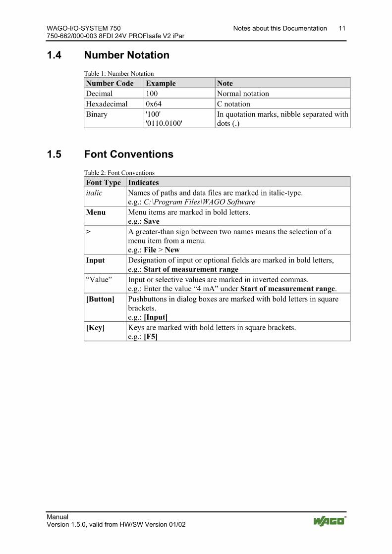
1.4 Number Notation Table 1: Number Notation Number Code Example Note Decimal 100 Normal notation Hexadecimal 0x64 C notation Binary '100'
'0110.0100' In quotation marks, nibble separated with dots (.)
Pos: 15.7 /Alle Serien (Allgemeine Module)/Hinweise zur Dokumentation/Schriftkonventionen - Überschrift 2 und Inhalt @ 3\mod_1221059521437_21.docx @ 21714 @ 2 @ 1
1.5 Font Conventions Table 2: Font Conventions Font Type Indicates italic Names of paths and data files are marked in italic-type.
e.g.: C:\Program Files\WAGO Software Menu Menu items are marked in bold letters.
e.g.: Save > A greater-than sign between two names means the selection of a
menu item from a menu. e.g.: File > New
Input Designation of input or optional fields are marked in bold letters, e.g.: Start of measurement range
“Value” Input or selective values are marked in inverted commas. e.g.: Enter the value “4 mA” under Start of measurement range.
[Button] Pushbuttons in dialog boxes are marked with bold letters in square brackets. e.g.: [Input]
[Key] Keys are marked with bold letters in square brackets. e.g.: [F5]
Pos: 16 /Dokumentation allgemein/Gliederungselemente/---Seitenwechsel--- @ 3\mod_1221108045078_0.docx @ 21810 @ @ 1
12 Important Notes WAGO-I/O-SYSTEM 750 750-662/000-003 8FDI 24V PROFIsafe V2 iPar
Manual Version 1.5.0, valid from HW/SW Version 01/02
Pos: 17 /Alle Serien (Allgemeine Module)/Überschriften für alle Serien/Wichtige Erläuterungen/Wichtige Erläuterungen - Überschrift 1 @ 4\mod_1241428899156_21.docx @ 32170 @ 1 @ 1
2 Important Notes Pos: 18.1 /Alle Serien (Allgemeine Dokumente) (Allgemeine Module)/Wichtige Erläuterungen/Wichtige Erläuterungen - Einleitung @ 3\mod_1221059818031_21.docx @ 21717 @ @ 1
This section includes an overall summary of the most important safety requirements and notes that are mentioned in each individual section. To protect your health and prevent damage to devices as well, it is imperative to read and carefully follow the safety guidelines.
Pos: 18.2 /Alle Serien (Allgemeine Module)/Überschriften für alle Serien/Wichtige ErläuterungenRechtliche Grundlagen - Überschrift 2 @ 3\mod_1221060626343_21.docx @ 21726 @ 2 @ 1
2.1 Legal Bases Pos: 18.3 /Alle Serien (Allgemeine Dokumente) (Allgemeine Module)/Wichtige Erläuterungen/Änderungsvorbehalt - Überschrift 3 und Inhalt @ 3\mod_1221060036484_21.docx @ 21720 @ 3 @ 1
2.1.1 Subject to Changes
WAGO Kontakttechnik GmbH & Co. KG reserves the right to provide for any alterations or modifications that serve to increase the efficiency of technical progress. WAGO Kontakttechnik GmbH & Co. KG owns all rights arising from the granting of patents or from the legal protection of utility patents. Third-party products are always mentioned without any reference to patent rights. Thus, the existence of such rights cannot be excluded.
Pos: 18.4 /Serie 750 (WAGO-I/O-SYSTEM)/Wichtige Erläuterungen/PersonalqualifikationPersonalqualifikation 750-xxxx - Überschrift 3 und Inhalt @ 3\mod_1224061208046_21.docx @ 24063 @ 3 @ 1
2.1.2 Personnel Qualifications
All sequences implemented on WAGO-I/O-SYSTEM 750 devices may only be carried out by electrical specialists with sufficient knowledge in automation. The specialists must be familiar with the current norms and guidelines for the devices and automated environments.
All changes to the coupler or controller should always be carried out by qualified personnel with sufficient skills in PLC programming.
Pos: 18.5 /Serie 750 (WAGO-I/O-SYSTEM)/Wichtige Erläuterungen/Sicherheits- und sonstige Hinweise/Gefahr/Gefahr: Austausch von PROFIsafe-Busklemmen nur durch sicherheitstechnisch sachkundige Personen @ 4\mod_1239786227890_21.docx @ 30470 @ @ 1
Only personnel trained in safety-related procedures may perform the work! Adding, exchanging and starting up PROFIsafe I/O modules may only be carried out by personnel trained in safety-related procedures!
Pos: 18.6 /Serie 750 (WAGO-I/O-SYSTEM)/Wichtige Erläuterungen/Bestimmungsgemäße VerwendungBestimmungsgemäße Verwendung 750-xxxx - Überschrift 3 und Inhalt @ 3\mod_1224064151234_21.docx @ 24070 @ 3 @ 1
2.1.3 Use of the WAGO-I/O-SYSTEM 750 in Compliance with Underlying Provisions
Fieldbus couplers, fieldbus controllers and I/O modules found in the modular WAGO-I/O-SYSTEM 750 receive digital and analog signals from sensors and transmit them to actuators or higher-level control systems. Using programmable controllers, the signals can also be (pre-) processed.
The devices have been developed for use in an environment that meets the IP20 protection class criteria. Protection against finger injury and solid impurities up to 12.5 mm diameter is assured; protection against water damage is not ensured. Unless otherwise specified, operation of the devices in wet and dusty environments is prohibited.
WAGO-I/O-SYSTEM 750 Important Notes 13 750-662/000-003 8FDI 24V PROFIsafe V2 iPar
Manual Version 1.5.0, valid from HW/SW Version 01/02
Operating the WAGO-I/O-SYSTEM 750 devices in home applications without further measures is only permitted if they meet the emission limits (emissions of interference) according to EN 61000-6-3. You will find the relevant information in the section “Device Description” > “Standards and Guidelines” in the manual for the used fieldbus coupler/controller.
Appropriate housing (per 94/9/EG) is required when operating the WAGO-I/O-SYSTEM 750 in hazardous environments. Please note that a prototype test certificate must be obtained that confirms the correct installation of the system in a housing or switch cabinet.
Pos: 18.7 /Alle Serien (Allgemeine Dokumente) (Allgemeine Module)/Wichtige Erläuterungen/Technischer Zustand der Geräte - Überschrift 3 und Inhalt @ 3\mod_1221060446109_21.docx @ 21723 @ 3 @ 1
2.1.4 Technical Condition of Specified Devices
The devices to be supplied ex works are equipped with hardware and software configurations, which meet the individual application requirements. WAGO Kontakttechnik GmbH & Co. KG will be exempted from any liability in case of changes in hardware or software as well as to non-compliant usage of devices.
Please send your request for modified and new hardware or software configurations directly to WAGO Kontakttechnik GmbH & Co. KG.
Pos: 18.8 /Dokumentation allgemein/Gliederungselemente/---Seitenwechsel--- @ 3\mod_1221108045078_0.docx @ 21810 @ @ 1
14 Important Notes WAGO-I/O-SYSTEM 750 750-662/000-003 8FDI 24V PROFIsafe V2 iPar
Manual Version 1.5.0, valid from HW/SW Version 01/02
Pos: 18.9 /Alle Serien (Allgemeine Module)/Überschriften für alle Serien/Wichtige ErläuterungenSicherheitshinweise - Überschrift 2 @ 6\mod_1260180299987_21.docx @ 46724 @ 2 @ 1
2.2 Safety Advice (Precautions) Pos: 18.10 /Alle Serien (Allgemeine Dokumente) (Allgemeine Module)/Wichtige Erläuterungen/Sicherheitshinweise/Einleitung Sicherheitshinweise Hardware @ 6\mod_1260180170493_21.docx @ 46720 @ @ 1
For installing and operating purposes of the relevant device to your system the following safety precautions shall be observed:
Pos: 18.11.1 /Alle Serien (Allgemeine Dokumente) (Allgemeine Module)/Wichtige Erläuterungen/Sicherheitshinweise/Gefahr/Gefahr: Nicht an Geräten unter Spannung arbeiten! @ 6\mod_1260180365327_21.docx @ 46727 @ @ 1
Do not work on devices while energized! All power sources to the device shall be switched off prior to performing any installation, repair or maintenance work.
Pos: 18.11.2 /Serie 750 (WAGO-I/O-SYSTEM)/Wichtige Erläuterungen/Sicherheits- und sonstige Hinweise/Gefahr/Gefahr: Einbau 0750-xxxx nur in Gehäusen, Schränken oder elektrischen Betriebsräumen! @ 6\mod_1260180556692_21.docx @ 46731 @ @ 1
Install the device only in appropriate housings, cabinets or in electrical operation rooms! The WAGO-I/O-SYSTEM 750 and its components are an open system. As such, install the system and its components exclusively in appropriate housings, cabinets or in electrical operation rooms. Allow access to such equipment and fixtures to authorized, qualified staff only by means of specific keys or tools.
Pos: 18.11.3 /Alle Serien (Allgemeine Dokumente) (Allgemeine Module)/Wichtige Erläuterungen/Sicherheitshinweise/Gefahr/Gefahr: Unfallverhütungsvorschriften beachten! @ 6\mod_1260180657000_21.docx @ 46735 @ @ 1
Pos: 18.11.4 /Alle Serien (Allgemeine Dokumente) (Allgemeine Module)/Wichtige Erläuterungen/Sicherheitshinweise/Gefahr/Gefahr: Auf normgerechten Anschluss achten! @ 6\mod_1260180753479_21.docx @ 46739 @ @ 1 Pos: 18.12 /Alle Serien (Allgemeine Dokumente) (Allgemeine Module)/Wichtige Erläuterungen/Sicherheitshinweise/Gefahr/Gefahr: Geltende Normen beachten! @ 10\mod_1305785142240_21.docx @ 72973 @ @ 1
Observe applicable standards! In a safety-related application, both the control as well as the attached sensors and actuators must meet the the applicable normative safety requirements. Ensure that switches, sensors and actuators comply with current applicable standards before use.
Pos: 18.13.1 /Alle Serien (Allgemeine Dokumente) (Allgemeine Module)/Wichtige Erläuterungen/Sicherheitshinweise/Achtung/Achtung: Defekte oder beschädigte Geräte austauschen! @ 6\mod_1260180857358_21.docx @ 46743 @ @ 1
Replace defective or damaged devices! Replace defective or damaged device/module (e.g., in the event of deformed contacts), since the long-term functionality of device/module involved can no longer be ensured.
Pos: 18.13.2 /Alle Serien (Allgemeine Dokumente) (Allgemeine Module)/Wichtige Erläuterungen/Sicherheitshinweise/Achtung/Achtung: Geräte vor kriechenden und isolierenden Stoffen schützen! @ 6\mod_1260181036216_21.docx @ 46747 @ @ 1
Protect the components against materials having seeping and insulating properties! The components are not resistant to materials having seeping and insulating properties such as: aerosols, silicones and triglycerides (found in some hand creams). If you cannot exclude that such materials will appear in the component environment, then install the components in an enclosure being resistant to the above-mentioned materials. Clean tools and materials are imperative for handling devices/modules.
Pos: 18.13.3 /Alle Serien (Allgemeine Dokumente) (Allgemeine Module)/Wichtige Erläuterungen/Sicherheitshinweise/Achtung/Achtung: Reinigung nur mit zulässigen Materialien! @ 6\mod_1260181203293_21.docx @ 46751 @ @ 1
WAGO-I/O-SYSTEM 750 Important Notes 15 750-662/000-003 8FDI 24V PROFIsafe V2 iPar
Manual Version 1.5.0, valid from HW/SW Version 01/02
Clean only with permitted materials! Clean soiled contacts using oil-free compressed air or with ethyl alcohol and leather cloths.
Pos: 18.13.4 /Alle Serien (Allgemeine Dokumente) (Allgemeine Module)/Wichtige Erläuterungen/Sicherheitshinweise/Achtung/Achtung: Kein Kontaktspray verwenden! @ 6\mod_1260181290808_21.docx @ 46755 @ @ 1
Do not use any contact spray! Do not use any contact spray. The spray may impair contact area functionality in connection with contamination.
Pos: 18.13.5 /Alle Serien (Allgemeine Dokumente) (Allgemeine Module)/Wichtige Erläuterungen/Sicherheitshinweise/Achtung/Achtung: Verpolung vermeiden! @ 6\mod_1260184045744_21.docx @ 46767 @ @ 1
Do not reverse the polarity of connection lines! Avoid reverse polarity of data and power supply lines, as this may damage the devices involved.
Pos: 18.13.6 /Alle Serien (Allgemeine Dokumente) (Allgemeine Module)/Wichtige Erläuterungen/Sicherheitshinweise/Achtung/Achtung: Elektrostatische Entladung vermeiden! @ 6\mod_1260181364729_21.docx @ 46759 @ @ 1
Avoid electrostatic discharge! The devices are equipped with electronic components that may be destroyed by electrostatic discharge when touched. Please observe the safety precautions against electrostatic discharge per DIN EN 61340-5-1/-3. When handling the devices, please ensure that environmental factors (personnel, work space and packaging) are properly grounded.
Pos: 18.14 /Alle Serien (Allgemeine Dokumente) (Allgemeine Module)/Wichtige Erläuterungen/Sicherheitshinweise/Achtung/Achtung: Leitfähige Verschmutzungen vermeiden! @ 10\mod_1305785013036_21.docx @ 72970 @ @ 1
Avoid conductive pollution! Suitable measures must be taken to prevent conductive pollution to achieve Pollution Degree II in accordance with EN61131-2. If you are unable to exclude that such materials will appear in the device environment, then install the devices in an enclosure that is resistant to the conductive materials. Clean tools and materials are imperative for handling devices.
Pos: 19 /Dokumentation allgemein/Gliederungselemente/---Seitenwechsel--- @ 3\mod_1221108045078_0.docx @ 21810 @ @ 1
16 PROFIsafe WAGO-I/O-SYSTEM 750 750-662/000-003 8FDI 24V PROFIsafe V2 iPar
Manual Version 1.5.0, valid from HW/SW Version 01/02
Pos: 20 /Serie 750 (WAGO-I/O-SYSTEM)/Systembeschreibung/PROFIsafe Allgemeine Beschreibung @ 4\mod_1235470712968_21.docx @ 27651 @ 1 @ 1
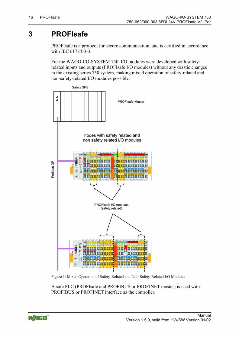
3 PROFIsafe PROFIsafe is a protocol for secure communication, and is certified in accordance with IEC 61784-3-3.
For the WAGO-I/O-SYSTEM 750, I/O modules were developed with safety-related inputs and outputs (PROFIsafe I/O modules) without any drastic changes to the existing series 750 system, making mixed operation of safety-related and non-safety-related I/O modules possible.
Figure 1: Mixed Operation of Safety-Related and Non-Safety-Related I/O Modules
A safe PLC (PROFIsafe and PROFIBUS or PROFINET master) is used with PROFIBUS or PROFINET interface as the controller.
WAGO-I/O-SYSTEM 750 PROFIsafe 17 750-662/000-003 8FDI 24V PROFIsafe V2 iPar
Manual Version 1.5.0, valid from HW/SW Version 01/02
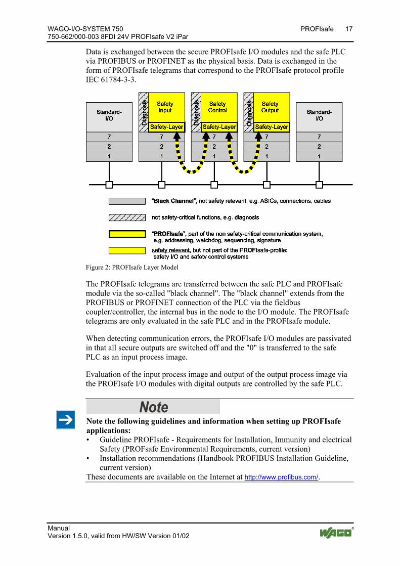
Data is exchanged between the secure PROFIsafe I/O modules and the safe PLC via PROFIBUS or PROFINET as the physical basis. Data is exchanged in the form of PROFIsafe telegrams that correspond to the PROFIsafe protocol profile IEC 61784-3-3.
Figure 2: PROFIsafe Layer Model
The PROFIsafe telegrams are transferred between the safe PLC and PROFIsafe module via the so-called "black channel". The "black channel" extends from the PROFIBUS or PROFINET connection of the PLC via the fieldbus coupler/controller, the internal bus in the node to the I/O module. The PROFIsafe telegrams are only evaluated in the safe PLC and in the PROFIsafe module.
When detecting communication errors, the PROFIsafe I/O modules are passivated in that all secure outputs are switched off and the "0" is transferred to the safe PLC as an input process image.
Evaluation of the input process image and output of the output process image via the PROFIsafe I/O modules with digital outputs are controlled by the safe PLC.
Note the following guidelines and information when setting up PROFIsafe applications: • Guideline PROFIsafe - Requirements for Installation, Immunity and electrical
Safety (PROFsafe Environmental Requirements, current version) • Installation recommendations (Handbook PROFIBUS Installation Guideline,
current version) These documents are available on the Internet at http://www.profibus.com/.
Pos: 21 /Serie 750 (WAGO-I/O-SYSTEM)/Systembeschreibung/iPar-Server @ 7\mod_1268385000661_21.docx @ 52430 @ 2 @ 1

18 PROFIsafe WAGO-I/O-SYSTEM 750 750-662/000-003 8FDI 24V PROFIsafe V2 iPar
Manual Version 1.5.0, valid from HW/SW Version 01/02
3.1 iPar Server The iPar parameters are used to configure device functions of a safe device such as the PROFIsafe I/O modules of the WAGO-I/O-SYSTEM 750/753. The “WAGO Safety Editor 75x” parameterization tool (SEDI) can be used to set the individual parameters of WAGO PROFIsafe I/O modules. SEDI is the CPD tool for WAGO PROFIsafe I/O modules.
Figure 3: iPar Server
Table 3: Legend for the iPar Server Figure No. Explanation 1 Instantiation of the iPar Server function 2 CPD Tool Start and parameter transfer (e.g., node address) 3 Parameterization of individual module parameters (iPar) and
commissioning; test and release 4 Transfer of iPar signature (CRC via the individual parameters) to the F-Host 5 During start-up, transfer of the signature to F-slave (Prm_Telegram) 6 Message to iPar server about diagnostic agent (alarm/status) 7 iPar server polls Diag FB and starts “Save” if required 8 iPar server polls Diag FB and starts “Restore” if required
It is often required during a repair to quickly replace a device without using additional manufacturer tools for parameterization of the device functions.
To meet this requirement, the iPar server is used that offers appropriate services for saving and restoring individual parameters. The “iPar Server” is available as a
WAGO-I/O-SYSTEM 750 PROFIsafe 19 750-662/000-003 8FDI 24V PROFIsafe V2 iPar
Manual Version 1.5.0, valid from HW/SW Version 01/02
function block or as a system function within the non-safety related part of the safe PLC.
Further details about using the iPar server in conjunction with the WAGO PROFIsafe I/O modules are available in an application note.
Use the application notes from WAGO! An overview for using the PROFIsafe I/O module in combination with a safe PLC is summarized in an application note. This application note is available on the Internet at www.wago.com under “Service > Downloads > Application Notes ...”
Pos: 22 /Dokumentation allgemein/Gliederungselemente/---Seitenwechsel--- @ 3\mod_1221108045078_0.docx @ 21810 @ @ 1
20 Device Description WAGO-I/O-SYSTEM 750 750-662/000-003 8FDI 24V PROFIsafe V2 iPar
Manual Version 1.5.0, valid from HW/SW Version 01/02
Pos: 23 /Alle Serien (Allgemeine Module)/Überschriften für alle Serien/Gerätebeschreibung/Gerätebeschreibung - Überschrift 1 @ 3\mod_1233756084656_21.docx @ 27096 @ 1 @ 1
4 Device Description Pos: 24.1.1 /Serie 750 (WAGO-I/O-SYSTEM)/Gerätebeschreibung/Einleitung/Anwendung/SO/Anwendung 750-066x/000-003 PROFIsafe Einleitung, mit DIN EN 61511:2004, SIL3 @ 12\mod_1340690521168_21.docx @ 98334 @ @ 1 </dg_
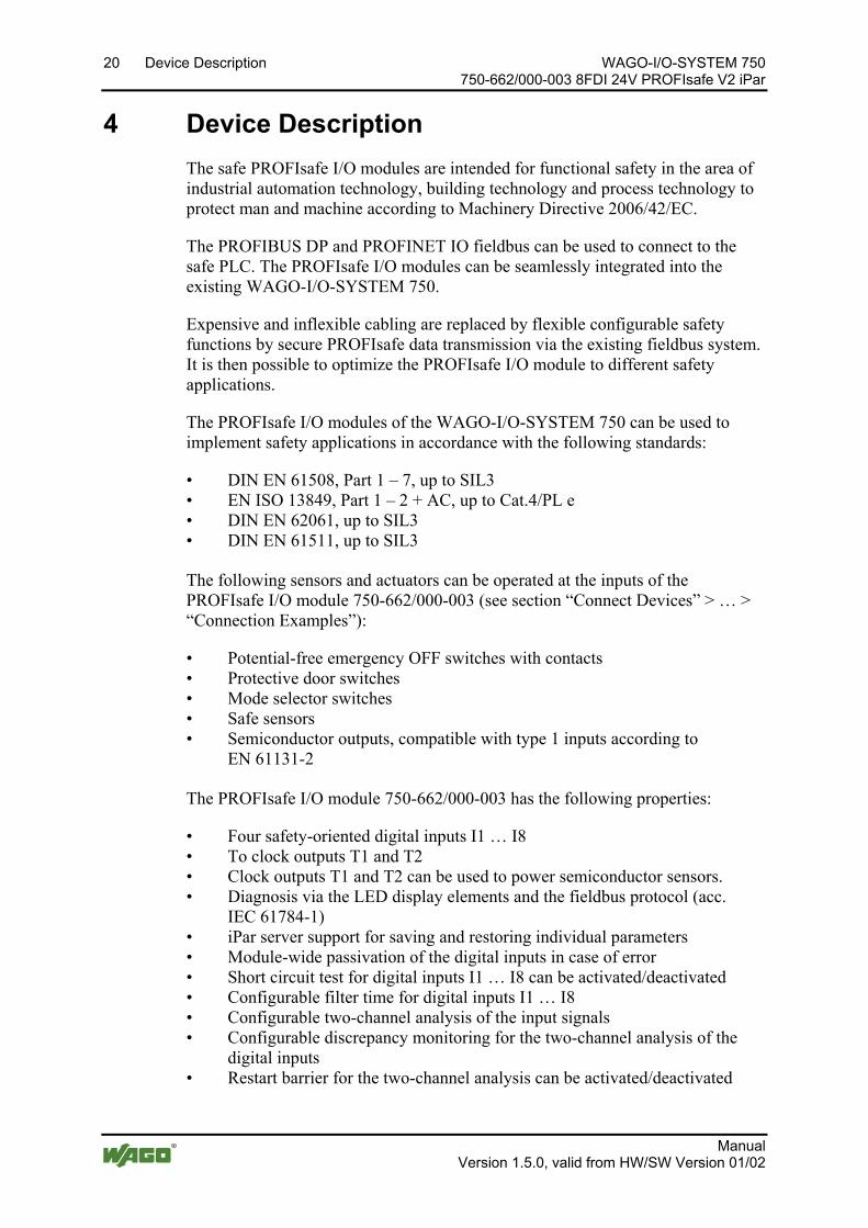
The safe PROFIsafe I/O modules are intended for functional safety in the area of industrial automation technology, building technology and process technology to protect man and machine according to Machinery Directive 2006/42/EC.
The PROFIBUS DP and PROFINET IO fieldbus can be used to connect to the safe PLC. The PROFIsafe I/O modules can be seamlessly integrated into the existing WAGO-I/O-SYSTEM 750.
Expensive and inflexible cabling are replaced by flexible configurable safety functions by secure PROFIsafe data transmission via the existing fieldbus system. It is then possible to optimize the PROFIsafe I/O module to different safety applications.
The PROFIsafe I/O modules of the WAGO-I/O-SYSTEM 750 can be used to implement safety applications in accordance with the following standards:
• DIN EN 61508, Part 1 – 7, up to SIL3 • EN ISO 13849, Part 1 – 2 + AC, up to Cat.4/PL e • DIN EN 62061, up to SIL3 • DIN EN 61511, up to SIL3
Pos: 24.1.2 /Serie 750 (WAGO-I/O-SYSTEM)/Gerätebeschreibung/Einleitung/Anwendung/SO/Anwendung 750-066x/000-003 PROFIsafe FDI @ 7\mod_1268750461577_21.docx @ 52650 @ @ 1
The following sensors and actuators can be operated at the inputs of the PROFIsafe I/O module 750-662/000-003 (see section “Connect Devices” > … > “Connection Examples”):
• Potential-free emergency OFF switches with contacts • Protective door switches • Mode selector switches • Safe sensors • Semiconductor outputs, compatible with type 1 inputs according to
EN 61131-2 Pos: 24.1.3 /Serie 750 (WAGO-I/O-SYSTEM)/Gerätebeschreibung/Einleitung/I/O-Beschreibung/SO/I/O-Beschreibung 750-0662/000-003 @ 7\mod_1268750121905_21.docx @ 52634 @ @ 1
The PROFIsafe I/O module 750-662/000-003 has the following properties:
• Four safety-oriented digital inputs I1 … I8 • To clock outputs T1 and T2 • Clock outputs T1 and T2 can be used to power semiconductor sensors. • Diagnosis via the LED display elements and the fieldbus protocol (acc.
IEC 61784-1) • iPar server support for saving and restoring individual parameters • Module-wide passivation of the digital inputs in case of error • Short circuit test for digital inputs I1 … I8 can be activated/deactivated • Configurable filter time for digital inputs I1 … I8 • Configurable two-channel analysis of the input signals • Configurable discrepancy monitoring for the two-channel analysis of the
digital inputs • Restart barrier for the two-channel analysis can be activated/deactivated

WAGO-I/O-SYSTEM 750 Device Description 21 750-662/000-003 8FDI 24V PROFIsafe V2 iPar
Manual Version 1.5.0, valid from HW/SW Version 01/02
• Rotary table / mode selector switch operating mode for digital inputs I1 … I8
Pos: 24.1.4 /Serie 750 (WAGO-I/O-SYSTEM)/Gerätebeschreibung/Einleitung/I/O-Beschreibung/Allgemein/Verweis auf Kapitel "Anschlüsse" @ 8\mod_1276775378035_21.docx @ 57956 @ @ 1
The assignment of the connections is described in the “Connectors” section. Pos: 24.1.5 /Serie 750 (WAGO-I/O-SYSTEM)/Gerätebeschreibung/Einleitung/I/O-Beschreibung/Allgemein/Verweis auf Kapitel "Geräte anschließen" > "Anschlussbeispiel(e)" @ 5\mod_1246015203281_21.docx @ 36298 @ @ 1
Connection examples are shown in section “Connecting Devices” > … > “Connection Example(s)”.
Pos: 24.1.6 /Serie 750 (WAGO-I/O-SYSTEM)/Gerätebeschreibung/Einleitung/LED-Anzeige/LED Zustand Signal Fehler PROFIsafe FDI FDO @ 4\mod_1240233303921_21.docx @ 30843 @ @ 1
Multicolor LEDs indicate the signal states of the inputs and outputs, as well as the status and errors of the PROFIsafe I/O module.
Pos: 24.1.7 /Serie 750 (WAGO-I/O-SYSTEM)/Gerätebeschreibung/Einleitung/LED-Anzeige/Verweis auf Kapitel "Anzeigeelemente" @ 5\mod_1246010525000_21.docx @ 36194 @ @ 1
The meaning of the LEDs is described in the “Display Elements” section. Pos: 24.1.8 /Serie 750 (WAGO-I/O-SYSTEM)/Wichtige Erläuterungen/Sicherheits- und sonstige Hinweise/Hinweis/Hinweis: PROFIsafe Einspeisekonzept beachten @ 7\mod_1265283290674_21.docx @ 49728 @ @ 1
Observe the information on the power supply concept! Detailed information and examples for supplying PROFIsafe I/O modules is available in the section “Connecting Devices” > … > "Power Supply Concept".
Pos: 24.1.9 /Serie 750 (WAGO-I/O-SYSTEM)/Gerätebeschreibung/Einleitung/Versorgung/Versorgung 24 V, 0 V über Leistungskontakte Standard @ 3\mod_1226498974531_21.docx @ 25020 @ @ 1
The I/O module 750-662/000-003 (8FDI 24V PROFIsafe V2 iPar) receives the 24 V voltage supply for the field level from an upstream I/O module or from the fieldbus coupler/controller via blade-formed power jumper contacts. It then provides these potentials to subsequent I/O modules via spring-formed power jumper contacts.
Pos: 24.1.10 /Serie 750 (WAGO-I/O-SYSTEM)/Gerätebeschreibung/Einleitung/Versorgung/Galvanische Trennung Feld/System @ 3\mod_1233756478750_21.docx @ 27102 @ @ 1
The field voltage and the system voltage are electrically isolated from each other. Pos: 24.1.11 /Serie 750 (WAGO-I/O-SYSTEM)/Gerätebeschreibung/Einleitung/Versorgung/Anordnung unter Berücksichtigung der Leistungskontakte beliebig @ 3\mod_1233756233468_21.docx @ 27099 @ @ 1
With consideration of the power jumper contacts, the individual modules can be arranged in any combination when configuring the fieldbus node. An arrangement in groups within the group of potentials is not necessary.
Pos: 24.1.12 /Serie 750 (WAGO-I/O-SYSTEM)/Gerätebeschreibung/Einleitung/Einsatzbereich/Einsatzbereich 75x-066x/000-003 @ 23\mod_1437391184128_21.docx @ 186490 @ @ 1
The PROFIsafe I/O module 750-662/000-003 can be operated on the WAGO-I/O-SYSTEM 750 fieldbus couplers specified in section “Technical Data” > … > “Communication”:
Pos: 24.2 /Dokumentation allgemein/Gliederungselemente/---Seitenwechsel--- @ 3\mod_1221108045078_0.docx @ 21810 @ @ 1

22 Device Description WAGO-I/O-SYSTEM 750 750-662/000-003 8FDI 24V PROFIsafe V2 iPar
Manual Version 1.5.0, valid from HW/SW Version 01/02
Pos: 24.3 /Alle Serien (Allgemeine Module)/Überschriften für alle Serien/Gerätebeschreibung/Ansicht - Überschrift 2 @ 4\mod_1240984217343_21.docx @ 31958 @ 2 @ 1
4.1 View Pos: 24.4 /Serie 750 (WAGO-I/O-SYSTEM)/Gerätebeschreibung/Ansicht/Sonderklemmen/Ansicht 750-0662/000-003 - Abb. @ 4\mod_1239874219093_21.docx @ 30563 @ @ 1
Figure 4: View
Pos: 24.5 /Serie 750 (WAGO-I/O-SYSTEM)/Gerätebeschreibung/Ansicht/Ansicht CageClamp®_Legende mit LEDs, mit 1 Entriegelungslasche @ 15\mod_1370867188922_21.docx @ 122225 @ @ 1
Table 4: Legend for Figure “View” Pos. Description Details See Section
1 Marking possibility with Mini-WSB
---
2 Status LEDs “Device Description” > “Display Elements” 3 Data contacts “Device Description” > “Connectors” 4 CAGE CLAMP® connectors “Device Description” > “Connectors” 5 Power jumper contacts “Device Description” > “Connectors” 6 Release tab “Mounting” > “Inserting and Removing
Devices”
Pos: 24.6 /Dokumentation allgemein/Gliederungselemente/---Seitenwechsel--- @ 3\mod_1221108045078_0.docx @ 21810 @ @ 1

WAGO-I/O-SYSTEM 750 Device Description 23 750-662/000-003 8FDI 24V PROFIsafe V2 iPar
Manual Version 1.5.0, valid from HW/SW Version 01/02
Pos: 24.7 /Alle Serien (Allgemeine Module)/Überschriften für alle Serien/Gerätebeschreibung/Anschlüsse - Überschrift 2 @ 4\mod_1240984262656_21.docx @ 31961 @ 2 @ 1
4.2 Connectors Pos: 24.8 /Serie 750 (WAGO-I/O-SYSTEM)/Gerätebeschreibung/Anschlüsse/Datenkontakte/Klemmenbus - Überschrift 3 @ 6\mod_1256294684083_21.docx @ 43660 @ 3 @ 1
4.2.1 Data Contacts/Internal Bus Pos: 24.9.1 /Serie 750 (WAGO-I/O-SYSTEM)/Gerätebeschreibung/Anschlüsse/Datenkontakte - Feldbuskoppler/-controller, Abbildung und Beschreibung @ 3\mod_1231771259187_21.docx @ 26002 @ @ 1
Communication between the fieldbus coupler/controller and the I/O modules as well as the system supply of the I/O modules is carried out via the internal bus. It is comprised of 6 data contacts, which are available as self-cleaning gold spring contacts.
Figure 5: Data Contacts Pos: 24.9.2 /Serie 750 (WAGO-I/O-SYSTEM)/Wichtige Erläuterungen/Sicherheits- und sonstige Hinweise/Achtung/Achtung: Busklemmen nicht auf Goldfederkontakte legen! @ 7\mod_1266318463636_21.docx @ 50695 @ @ 1
Do not place the I/O modules on the gold spring contacts! Do not place the I/O modules on the gold spring contacts in order to avoid soiling or scratching!
Pos: 24.9.3 /Serie 750 (WAGO-I/O-SYSTEM)/Wichtige Erläuterungen/Sicherheits- und sonstige Hinweise/Achtung/Achtung: ESD - Auf gute Erdung der Umgebung achten! @ 7\mod_1266318538667_21.docx @ 50708 @ @ 1
Ensure that the environment is well grounded! The devices are equipped with electronic components that may be destroyed by electrostatic discharge. When handling the devices, ensure that the environment (persons, workplace and packing) is well grounded. Avoid touching conductive components, e.g. data contacts.
Pos: 24.10 /Dokumentation allgemein/Gliederungselemente/---Seitenwechsel--- @ 3\mod_1221108045078_0.docx @ 21810 @ @ 1
24 Device Description WAGO-I/O-SYSTEM 750 750-662/000-003 8FDI 24V PROFIsafe V2 iPar
Manual Version 1.5.0, valid from HW/SW Version 01/02
Pos: 24.11 /Serie 750 (WAGO-I/O-SYSTEM)/Gerätebeschreibung/Anschlüsse/Leistungskontakte/Feldversorgung - Überschrift 3 @ 6\mod_1256294692864_21.docx @ 43664 @ 3 @ 1
4.2.2 Power Jumper Contacts/Field Supply Pos: 24.12.1 /Serie 750 (WAGO-I/O-SYSTEM)/Wichtige Erläuterungen/Sicherheits- und sonstige Hinweise/Vorsicht/Vorsicht: Verletzungsgefahr durch scharfkantige Messerkontakte! @ 6\mod_1256193279401_21.docx @ 43414 @ @ 1
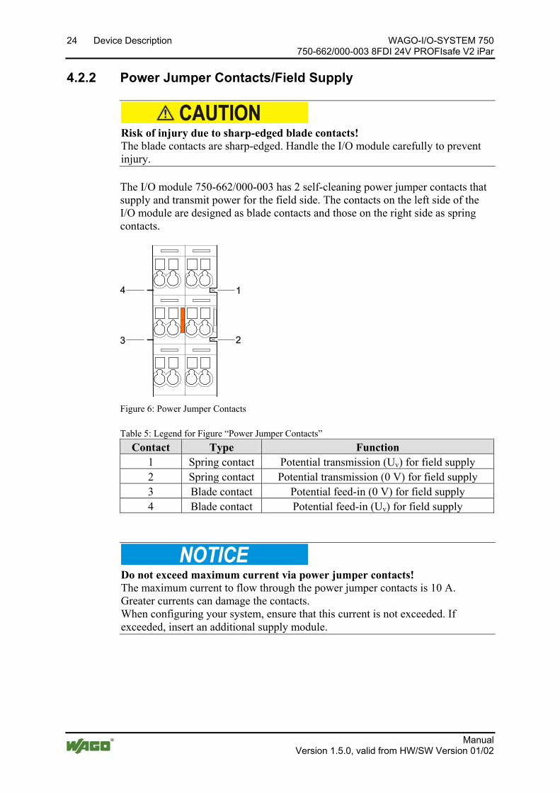
Risk of injury due to sharp-edged blade contacts! The blade contacts are sharp-edged. Handle the I/O module carefully to prevent injury.
Pos: 24.12.2 /Serie 750 (WAGO-I/O-SYSTEM)/Gerätebeschreibung/Anschlüsse/Leistungskontakte 2 LK (Messer/Leistungskontakte 2 LK (Messer/Feder) - Einleitung @ 15\mod_1371721641099_21.docx @ 123714 @ @ 1
The I/O module 750-662/000-003 has 2 self-cleaning power jumper contacts that supply and transmit power for the field side. The contacts on the left side of the I/O module are designed as blade contacts and those on the right side as spring contacts.
Pos: 24.12.3 /Serie 750 (WAGO-I/O-SYSTEM)/Gerätebeschreibung/Anschlüsse/Leistungskontakte 2 LK (Messer/Leistungskontakte 2 LK (Messer/Feder) - Abbildung, doppelte Breite @ 15\mod_1371721756578_21.docx @ 123718 @ @ 1
Figure 6: Power Jumper Contacts Pos: 24.12.4 /Serie 750 (WAGO-I/O-SYSTEM)/Gerätebeschreibung/Anschlüsse/Leistungskontakte 2 LK (Messer/Leistungskontakte 2 LK (Messer/Feder) - Legende @ 15\mod_1371721352500_21.docx @ 123710 @ @ 1
Table 5: Legend for Figure “Power Jumper Contacts” Contact Type Function
1 Spring contact Potential transmission (Uv) for field supply 2 Spring contact Potential transmission (0 V) for field supply 3 Blade contact Potential feed-in (0 V) for field supply 4 Blade contact Potential feed-in (Uv) for field supply
Pos: 24.12.5 /Serie 750 (WAGO-I/O-SYSTEM)/Wichtige Erläuterungen/Sicherheits- und sonstige Hinweise/Achtung/Achtung: Maximaler Strom Leistungskontakte 10 A @ 3\mod_1226499143500_21.docx @ 25029 @ @ 1
Do not exceed maximum current via power jumper contacts! The maximum current to flow through the power jumper contacts is 10 A. Greater currents can damage the contacts. When configuring your system, ensure that this current is not exceeded. If exceeded, insert an additional supply module.
Pos: 24.12.6 /Serie 750 (WAGO-I/O-SYSTEM)/Wichtige Erläuterungen/Sicherheits- und sonstige Hinweise/Hinweis/Hinweis: Potentialeinspeiseklemme für Erde einsetzen! (keine LK für Erde) @ 3\mod_1226499037468_21.docx @ 25023 @ @ 1
WAGO-I/O-SYSTEM 750 Device Description 25 750-662/000-003 8FDI 24V PROFIsafe V2 iPar
Manual Version 1.5.0, valid from HW/SW Version 01/02
Use supply modules for ground (earth)! The I/O module has no power jumper contacts for receiving and transmitting the earth potential. Use a supply module when an earth potential is needed for the subsequent I/O modules.
Pos: 24.13 /Serie 750 (WAGO-I/O-SYSTEM)/Wichtige Erläuterungen/Sicherheits- und sonstige Hinweise/Hinweis/Hinweis: PROFIsafe Einspeisekonzept beachten @ 7\mod_1265283290674_21.docx @ 49728 @ @ 1
Observe the information on the power supply concept! Detailed information and examples for supplying PROFIsafe I/O modules is available in the section “Connecting Devices” > … > "Power Supply Concept".
Pos: 24.14 /Dokumentation allgemein/Gliederungselemente/---Seitenwechsel--- @ 3\mod_1221108045078_0.docx @ 21810 @ @ 1
26 Device Description WAGO-I/O-SYSTEM 750 750-662/000-003 8FDI 24V PROFIsafe V2 iPar
Manual Version 1.5.0, valid from HW/SW Version 01/02
Pos: 24.15 /Serie 750 (WAGO-I/O-SYSTEM)/Gerätebeschreibung/Anschlüsse/CAGE CLAMP-Anschlüsse - Überschrift 3 @ 6\mod_1256296337770_21.docx @ 43674 @ 3 @ 1
4.2.3 CAGE CLAMP® Connectors Pos: 24.16 /Serie 750 (WAGO-I/O-SYSTEM)/Gerätebeschreibung/Anschlüsse/Sonderklemmen/Anschlüsse CC 750-0662/000-003 @ 4\mod_1240227710140_21.docx @ 30760 @ @ 1
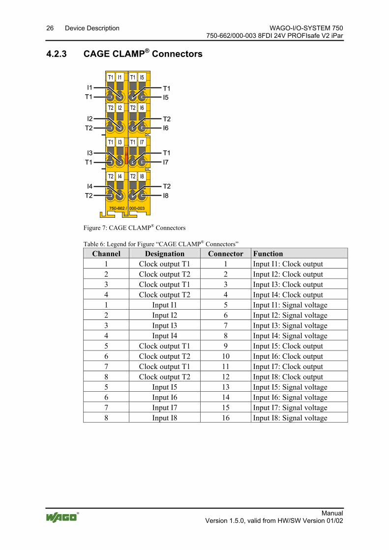
Figure 7: CAGE CLAMP® Connectors
Table 6: Legend for Figure “CAGE CLAMP® Connectors” Channel Designation Connector Function
1 Clock output T1 1 Input I1: Clock output 2 Clock output T2 2 Input I2: Clock output 3 Clock output T1 3 Input I3: Clock output 4 Clock output T2 4 Input I4: Clock output 1 Input I1 5 Input I1: Signal voltage 2 Input I2 6 Input I2: Signal voltage 3 Input I3 7 Input I3: Signal voltage 4 Input I4 8 Input I4: Signal voltage 5 Clock output T1 9 Input I5: Clock output 6 Clock output T2 10 Input I6: Clock output 7 Clock output T1 11 Input I7: Clock output 8 Clock output T2 12 Input I8: Clock output 5 Input I5 13 Input I5: Signal voltage 6 Input I6 14 Input I6: Signal voltage 7 Input I7 15 Input I7: Signal voltage 8 Input I8 16 Input I8: Signal voltage
Pos: 24.17 /Dokumentation allgemein/Gliederungselemente/---Seitenwechsel--- @ 3\mod_1221108045078_0.docx @ 21810 @ @ 1

WAGO-I/O-SYSTEM 750 Device Description 27 750-662/000-003 8FDI 24V PROFIsafe V2 iPar
Manual Version 1.5.0, valid from HW/SW Version 01/02
Pos: 24.18 /Alle Serien (Allgemeine Module)/Überschriften für alle Serien/Gerätebeschreibung/Anzeigeelemente - Überschrift 2 @ 4\mod_1240984390875_21.docx @ 31964 @ 2 @ 1
4.3 Display Elements Pos: 24.19 /Serie 750 (WAGO-I/O-SYSTEM)/Gerätebeschreibung/Anzeigeelemente/Sonderklemmen/Anzeigeelemente 750-066x Eingänge 1 - 4 @ 7\mod_1273654138286_21.docx @ 56444 @ @ 1
Figure 8: Display Elements, Inputs 1 ... 4
Table 7: Legend for Figure “Display Elements, Inputs 1 ... 4” Channel Designation LED Status Function
1 Status I1 A
Off Input I1: Signal voltage (0) Green Input I1: Signal voltage (1) Red Input I1: Error
2 Status I2 B
Off Input I2: Signal voltage (0) Green Input I2: Signal voltage (1) Red Input I2: Error
3 Status I3 C
Off Input I3: Signal voltage (0) Green Input I3: Signal voltage (1) Red Input I3: Error
4 Status I4 D
Off Input I4: Signal voltage (0) Green Input I4: Signal voltage (1) Red Input I4: Error
Pos: 24.20 /Dokumentation allgemein/Gliederungselemente/---Seitenwechsel--- @ 3\mod_1221108045078_0.docx @ 21810 @ @ 1
28 Device Description WAGO-I/O-SYSTEM 750 750-662/000-003 8FDI 24V PROFIsafe V2 iPar
Manual Version 1.5.0, valid from HW/SW Version 01/02
Pos: 24.21 /Serie 750 (WAGO-I/O-SYSTEM)/Gerätebeschreibung/Anzeigeelemente/Sonderklemmen/Anzeigeelemente 750-0662 Eingänge I-M @ 7\mod_1273654136021_21.docx @ 56432 @ @ 1
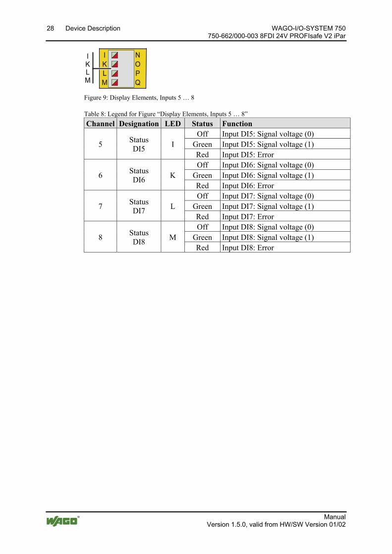
Figure 9: Display Elements, Inputs 5 … 8
Table 8: Legend for Figure “Display Elements, Inputs 5 … 8” Channel Designation LED Status Function
5 Status DI5 I
Off Input DI5: Signal voltage (0) Green Input DI5: Signal voltage (1) Red Input DI5: Error
6 Status DI6 K
Off Input DI6: Signal voltage (0) Green Input DI6: Signal voltage (1) Red Input DI6: Error
7 Status DI7 L
Off Input DI7: Signal voltage (0) Green Input DI7: Signal voltage (1) Red Input DI7: Error
8 Status DI8 M
Off Input DI8: Signal voltage (0) Green Input DI8: Signal voltage (1) Red Input DI8: Error
Pos: 24.22 /Dokumentation allgemein/Gliederungselemente/---Seitenwechsel--- @ 3\mod_1221108045078_0.docx @ 21810 @ @ 1
WAGO-I/O-SYSTEM 750 Device Description 29 750-662/000-003 8FDI 24V PROFIsafe V2 iPar
Manual Version 1.5.0, valid from HW/SW Version 01/02
Pos: 24.23 /Serie 750 (WAGO-I/O-SYSTEM)/Gerätebeschreibung/Anzeigeelemente/Sonderklemmen/Anzeigeelemente 750-066x Kommunikation @ 7\mod_1273653565475_21.docx @ 56428 @ @ 1
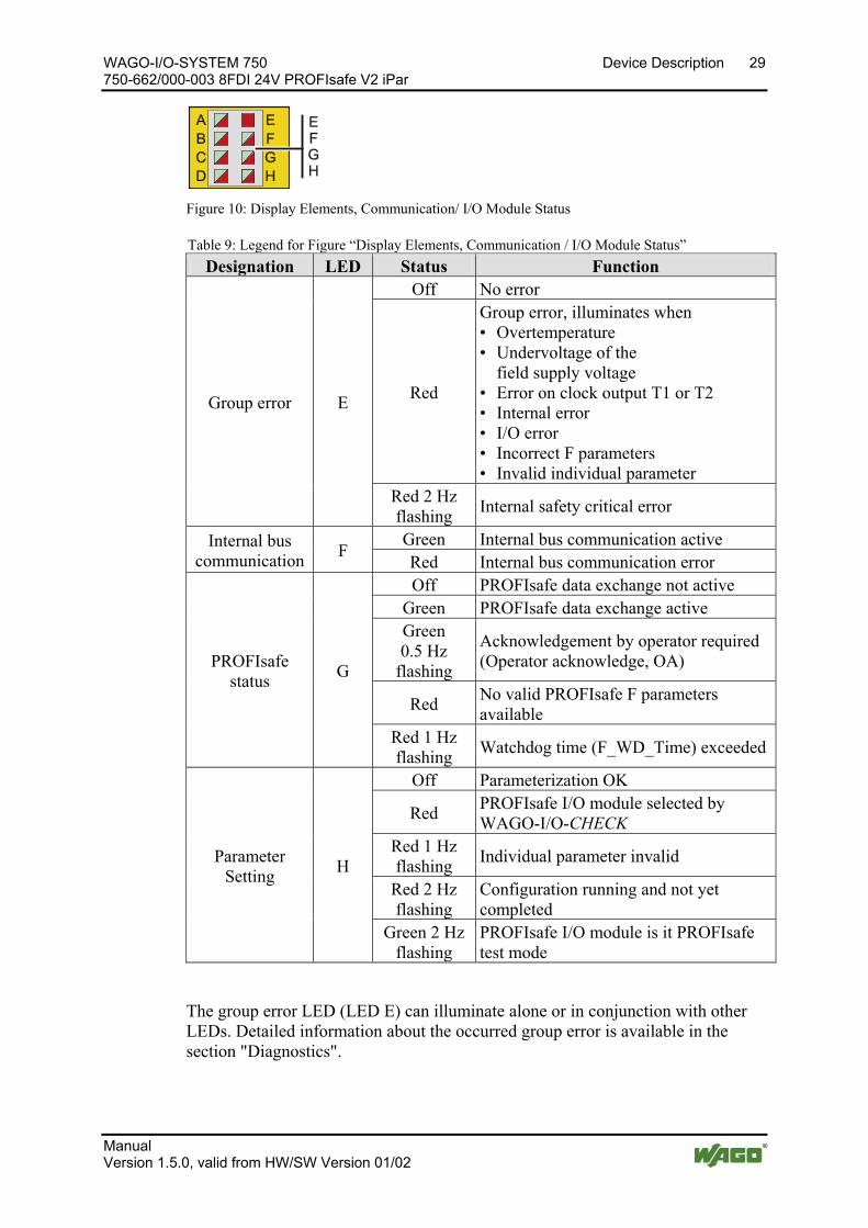
Figure 10: Display Elements, Communication/ I/O Module Status
Table 9: Legend for Figure “Display Elements, Communication / I/O Module Status” Designation LED Status Function
Group error E
Off No error
Red
Group error, illuminates when • Overtemperature • Undervoltage of the field supply voltage • Error on clock output T1 or T2 • Internal error • I/O error • Incorrect F parameters • Invalid individual parameter
Red 2 Hz flashing Internal safety critical error
Internal bus communication F Green Internal bus communication active
Red Internal bus communication error
PROFIsafe status G
Off PROFIsafe data exchange not active Green PROFIsafe data exchange active Green 0.5 Hz
flashing
Acknowledgement by operator required (Operator acknowledge, OA)
Red No valid PROFIsafe F parameters available
Red 1 Hz flashing Watchdog time (F_WD_Time) exceeded
Parameter Setting H
Off Parameterization OK
Red PROFIsafe I/O module selected by WAGO-I/O-CHECK
Red 1 Hz flashing Individual parameter invalid
Red 2 Hz flashing
Configuration running and not yet completed
Green 2 Hz flashing
PROFIsafe I/O module is it PROFIsafe test mode
The group error LED (LED E) can illuminate alone or in conjunction with other LEDs. Detailed information about the occurred group error is available in the section "Diagnostics".

30 Device Description WAGO-I/O-SYSTEM 750 750-662/000-003 8FDI 24V PROFIsafe V2 iPar
Manual Version 1.5.0, valid from HW/SW Version 01/02
Behavior when group error LED (LED E) is flashing A flashing group error LED (LED E) indicates that the PROFIsafe I/O module has detected an internal safety critical error. The cause can be a defect in the PROFIsafe I/O module or an environmental EMC error. In this case, switch off the PROFIsafe I/O module completely and the switch it back on. If the problem occurs several times, it points to a defect in the PROFIsafe I/O module. In this case, return the PROFIsafe I/O module to WAGO Kontakttechnik GmbH & Co. KG for fault analysis.
Pos: 24.24 /Dokumentation allgemein/Gliederungselemente/---Seitenwechsel--- @ 3\mod_1221108045078_0.docx @ 21810 @ @ 1

WAGO-I/O-SYSTEM 750 Device Description 31 750-662/000-003 8FDI 24V PROFIsafe V2 iPar
Manual Version 1.5.0, valid from HW/SW Version 01/02
Pos: 24.25 /Alle Serien (Allgemeine Module)/Überschriften für alle Serien/Gerätebeschreibung/Bedienelemente - Überschrift 2 @ 4\mod_1239191655456_21.docx @ 30439 @ 2 @ 1
4.4 Operating Elements Pos: 24.26 /Serie 750 (WAGO-I/O-SYSTEM)/Gerätebeschreibung/Bedienelemente/Busklemmen/Bedienelemente 75x-066x/000-003 @ 7\mod_1265287420132_21.docx @ 49740 @ @ 1
You can use the coding switch located on the side of the PROFIsafe I/O module to set the PROFIsafe address.
Figure 11: Coding Switch for the PROFIsafe Address (set to 1018)
Coding switch is inaccessible when the I/O module is plugged in! To set the PROFIsafe address on the coding switch, you must power down the fieldbus node and then unplug the I/O module from the fieldbus node.
Set the PROFIsafe address as described in the section "Setting the PROFIsafe Address".
Pos: 24.27 /Dokumentation allgemein/Gliederungselemente/---Seitenwechsel--- @ 3\mod_1221108045078_0.docx @ 21810 @ @ 1

32 Device Description WAGO-I/O-SYSTEM 750 750-662/000-003 8FDI 24V PROFIsafe V2 iPar
Manual Version 1.5.0, valid from HW/SW Version 01/02
Pos: 24.28 /Alle Serien (Allgemeine Module)/Überschriften für alle Serien/Gerätebeschreibung/Schematische Schaltbilder - Überschrift 2 @ 4\mod_1240984580875_21.docx @ 31970 @ 2 @ 1
4.5 Schematic Diagrams Pos: 24.29 /Serie 750 (WAGO-I/O-SYSTEM)/Gerätebeschreibung/Schematische Schaltbilder/Sonderklemmen/Schematisches Schaltbild 750-0662/000-003 PROFIsafe @ 23\mod_1439539651384_21.docx @ 188925 @ @ 1
Figure 12: Schematic Diagram
Pos: 24.30 /Serie 750 (WAGO-I/O-SYSTEM)/Gerätebeschreibung/Schematische Schaltbilder/Sonderklemmen/Prinzipschaltbild 75x-066x/000-003 PROFIsafe-Eingang @ 7\mod_1265287782311_21.docx @ 49762 @ 3 @ 1
4.5.1 Input Block Diagram
Figure 13: Input Block Diagram Pos: 24.31 /Dokumentation allgemein/Gliederungselemente/---Seitenwechsel--- @ 3\mod_1221108045078_0.docx @ 21810 @ @ 1
WAGO-I/O-SYSTEM 750 Device Description 33 750-662/000-003 8FDI 24V PROFIsafe V2 iPar
Manual Version 1.5.0, valid from HW/SW Version 01/02
Pos: 24.32 /Alle Serien (Allgemeine Module)/Überschriften für alle Serien/Gerätebeschreibung/Technische Daten - Überschrift 2 @ 3\mod_1232967587687_21.docx @ 26924 @ 2 @ 1
4.6 Technical Data Pos: 24.33 /Serie 750 (WAGO-I/O-SYSTEM)/Gerätebeschreibung/Technische Daten/Sonderklemmen/Technische Daten 75x-0662/000-003 @ 6\mod_1265037832968_21.docx @ 49145 @ 33333 @ 1 </dg_
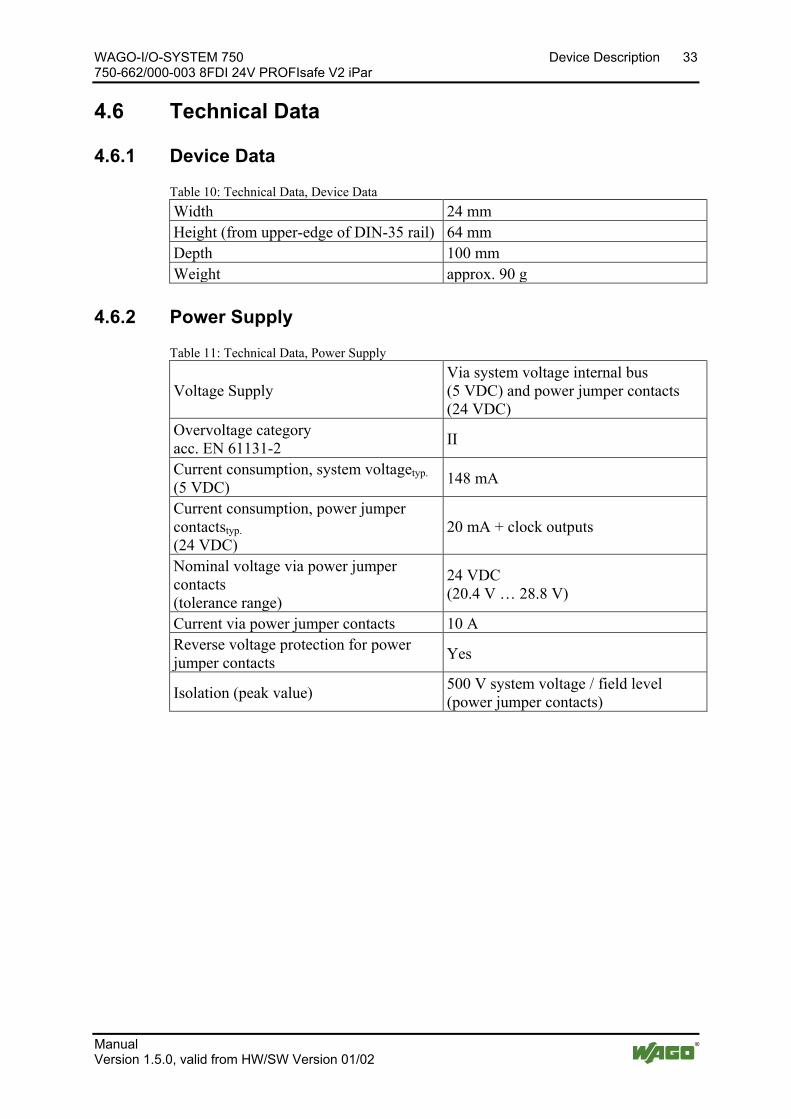
4.6.1 Device Data
Table 10: Technical Data, Device Data Width 24 mm Height (from upper-edge of DIN-35 rail) 64 mm Depth 100 mm Weight approx. 90 g
4.6.2 Power Supply
Table 11: Technical Data, Power Supply
Voltage Supply Via system voltage internal bus (5 VDC) and power jumper contacts (24 VDC)
Overvoltage category acc. EN 61131-2 II
Current consumption, system voltagetyp. (5 VDC) 148 mA
Current consumption, power jumper contactstyp. (24 VDC)
20 mA + clock outputs
Nominal voltage via power jumper contacts (tolerance range)
24 VDC (20.4 V … 28.8 V)
Current via power jumper contacts 10 A Reverse voltage protection for power jumper contacts Yes
Isolation (peak value) 500 V system voltage / field level (power jumper contacts)

34 Device Description WAGO-I/O-SYSTEM 750 750-662/000-003 8FDI 24V PROFIsafe V2 iPar
Manual Version 1.5.0, valid from HW/SW Version 01/02
4.6.3 Communication
Table 12: Technical Data, Communication
Usable fieldbus couplers / controllers
750-333 SW 14, HW 16 or higher 750-370 SW 02, HW 01 or higher 750-375 SW 02, HW 01 or higher 750-377 SW 02, HW 01 or higher
GSD specification V5 No. of PROFIsafe I/O modules per node (fieldbus couplers / controllers)max.
See information in handbook about the respective fieldbus coupler/controller
PROFIsafe F Parameter
F_Check_SeqNr No Check/Check (depending on PLC)
F_iPar_CRC 0 … 65535
F_Block_ID 0 / 1 for 750-333 and 750-370 1 for 750-375 and 750-377
F_SIL SIL3
F_CRC_Length 2 Byte (PROFIsafe V1) / 3 Byte (PROFIsafe V2)
F_Par_Version PROFIsafe V1 / PROFIsafe V2 F_Dest_Addr 1 … 65534 F_WD_Time 50 ms … 10000 ms
Channel diagnostic messages Can be switched on/off for entire PROFIsafe I/O module
Acknowledgement path F_Ack Available in software version 08 and higher
WAGO-I/O-SYSTEM 750 Device Description 35 750-662/000-003 8FDI 24V PROFIsafe V2 iPar
Manual Version 1.5.0, valid from HW/SW Version 01/02
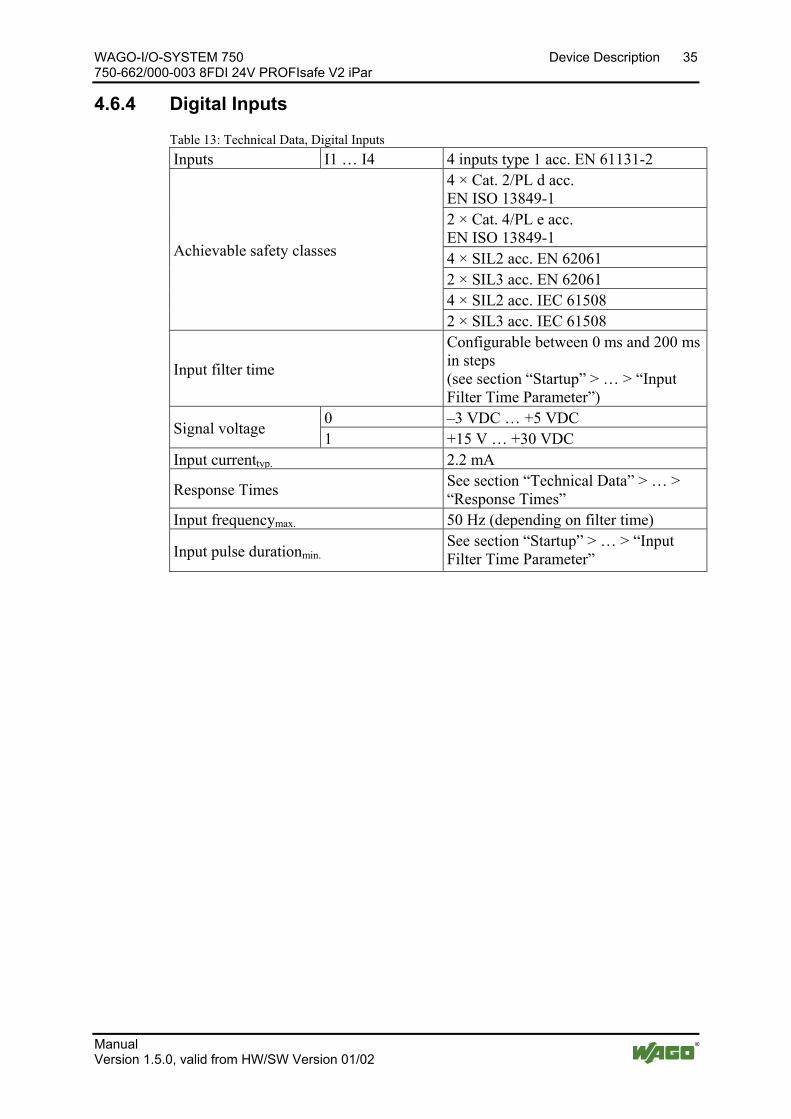
4.6.4 Digital Inputs
Table 13: Technical Data, Digital Inputs Inputs I1 … I4 4 inputs type 1 acc. EN 61131-2
Achievable safety classes
4 × Cat. 2/PL d acc. EN ISO 13849-1 2 × Cat. 4/PL e acc. EN ISO 13849-1 4 × SIL2 acc. EN 62061 2 × SIL3 acc. EN 62061 4 × SIL2 acc. IEC 61508 2 × SIL3 acc. IEC 61508
Input filter time
Configurable between 0 ms and 200 ms in steps (see section “Startup” > … > “Input Filter Time Parameter”)
Signal voltage 0 –3 VDC … +5 VDC 1 +15 V … +30 VDC
Input currenttyp. 2.2 mA
Response Times See section “Technical Data” > … > “Response Times”
Input frequencymax. 50 Hz (depending on filter time)
Input pulse durationmin. See section “Startup” > … > “Input Filter Time Parameter”
36 Device Description WAGO-I/O-SYSTEM 750 750-662/000-003 8FDI 24V PROFIsafe V2 iPar
Manual Version 1.5.0, valid from HW/SW Version 01/02
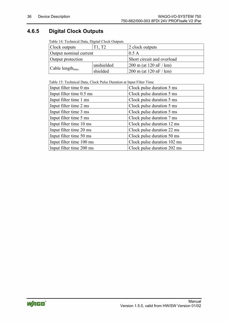
4.6.5 Digital Clock Outputs
Table 14: Technical Data, Digital Clock Outputs Clock outputs T1, T2 2 clock outputs Output nominal current 0.5 A Output protection Short circuit and overload
Cable lengthmax. unshielded 200 m (at 120 nF / km) shielded 200 m (at 120 nF / km)
Table 15: Technical Data, Clock Pulse Duration at Input Filter Time Input filter time 0 ms Clock pulse duration 5 ms Input filter time 0.5 ms Clock pulse duration 5 ms Input filter time 1 ms Clock pulse duration 5 ms Input filter time 2 ms Clock pulse duration 5 ms Input filter time 3 ms Clock pulse duration 5 ms Input filter time 5 ms Clock pulse duration 7 ms Input filter time 10 ms Clock pulse duration 12 ms Input filter time 20 ms Clock pulse duration 22 ms Input filter time 50 ms Clock pulse duration 50 ms Input filter time 100 ms Clock pulse duration 102 ms Input filter time 200 ms Clock pulse duration 202 ms
Pos: 24.34 /Serie 750 (WAGO-I/O-SYSTEM)/Gerätebeschreibung/Technische Daten/Sonderklemmen/Technische Daten 75x-0662/000-003 Sicherheitstechnische Kennwerte @ 23\mod_1440141529376_21.docx @ 189996 @ 34444 @ 1
WAGO-I/O-SYSTEM 750 Device Description 37 750-662/000-003 8FDI 24V PROFIsafe V2 iPar
Manual Version 1.5.0, valid from HW/SW Version 01/02
4.6.6 Safety Parameters
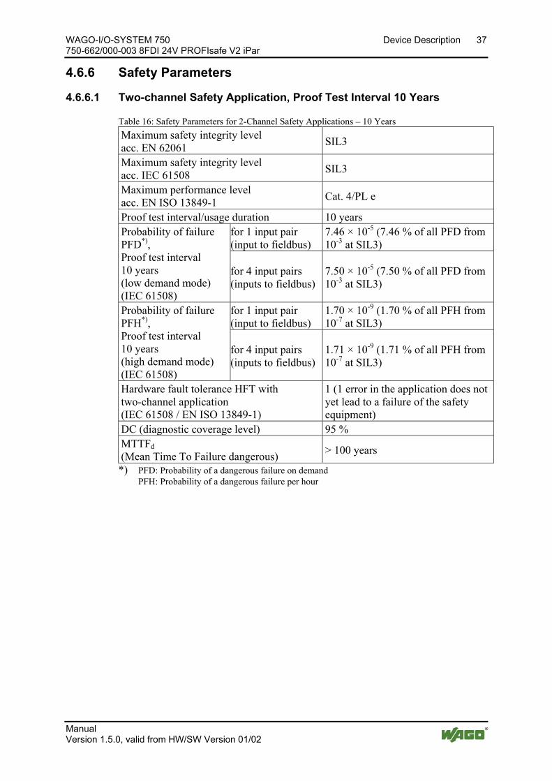
4.6.6.1 Two-channel Safety Application, Proof Test Interval 10 Years
Table 16: Safety Parameters for 2-Channel Safety Applications – 10 Years Maximum safety integrity level acc. EN 62061 SIL3
Maximum safety integrity level acc. IEC 61508 SIL3
Maximum performance level acc. EN ISO 13849-1 Cat. 4/PL e
Proof test interval/usage duration 10 years Probability of failure PFD*), Proof test interval 10 years (low demand mode) (IEC 61508)
for 1 input pair (input to fieldbus)
7.46 × 10⁻⁵ (7.46 % of all PFD from 10-3 at SIL3)
for 4 input pairs (inputs to fieldbus)
7.50 × 10⁻⁵ (7.50 % of all PFD from 10-3 at SIL3)
Probability of failure PFH*), Proof test interval 10 years (high demand mode) (IEC 61508)
for 1 input pair (input to fieldbus)
1.70 × 10⁻⁹ (1.70 % of all PFH from 10-7 at SIL3)
for 4 input pairs (inputs to fieldbus)
1.71 × 10⁻⁹ (1.71 % of all PFH from 10-7 at SIL3)
Hardware fault tolerance HFT with two-channel application (IEC 61508 / EN ISO 13849-1)
1 (1 error in the application does not yet lead to a failure of the safety equipment)
DC (diagnostic coverage level) 95 % MTTFd (Mean Time To Failure dangerous) > 100 years
*) PFD: Probability of a dangerous failure on demand PFH: Probability of a dangerous failure per hour
38 Device Description WAGO-I/O-SYSTEM 750 750-662/000-003 8FDI 24V PROFIsafe V2 iPar
Manual Version 1.5.0, valid from HW/SW Version 01/02
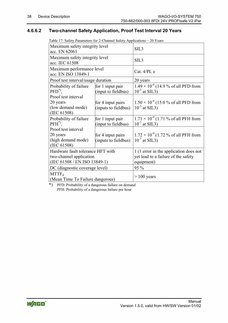
4.6.6.2 Two-channel Safety Application, Proof Test Interval 20 Years
Table 17: Safety Parameters for 2-Channel Safety Applications – 20 Years Maximum safety integrity level acc. EN 62061 SIL3
Maximum safety integrity level acc. IEC 61508 SIL3
Maximum performance level acc. EN ISO 13849-1 Cat. 4/PL e
Proof test interval/usage duration 20 years Probability of failure PFD*), Proof test interval 20 years (low demand mode) (IEC 61508)
for 1 input pair (input to fieldbus)
1.49 × 10⁻⁴ (14.9 % of all PFD from 10-3 at SIL3)
for 4 input pairs (inputs to fieldbus)
1.50 × 10⁻⁴ (15.0 % of all PFD from 10-3 at SIL3)
Probability of failure PFH*), Proof test interval 20 years (high demand mode) (IEC 61508)
for 1 input pair (input to fieldbus)
1.71 × 10⁻⁹ (1.71 % of all PFH from 10-7 at SIL3)
for 4 input pairs (inputs to fieldbus)
1.72 × 10⁻⁹ (1.72 % of all PFH from 10-7 at SIL3)
Hardware fault tolerance HFT with two-channel application (IEC 61508 / EN ISO 13849-1)
1 (1 error in the application does not yet lead to a failure of the safety equipment)
DC (diagnostic coverage level) 95 % MTTFd (Mean Time To Failure dangerous) > 100 years
*) PFD: Probability of a dangerous failure on demand PFH: Probability of a dangerous failure per hour
WAGO-I/O-SYSTEM 750 Device Description 39 750-662/000-003 8FDI 24V PROFIsafe V2 iPar
Manual Version 1.5.0, valid from HW/SW Version 01/02
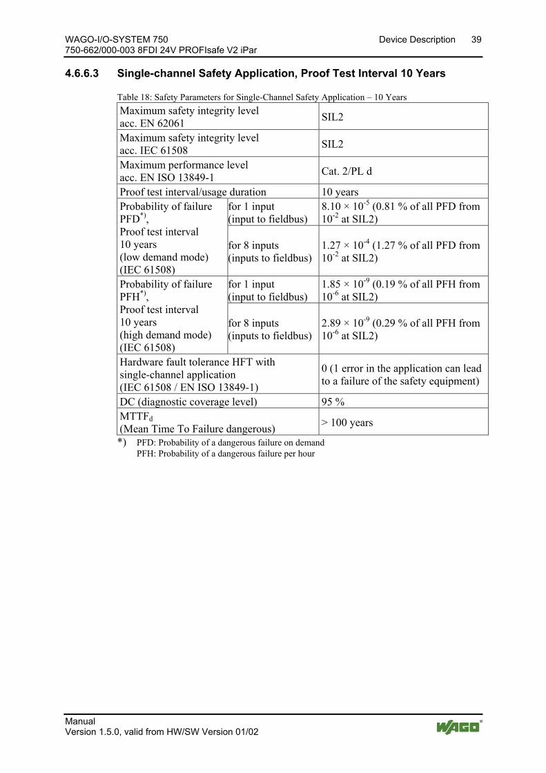
4.6.6.3 Single-channel Safety Application, Proof Test Interval 10 Years
Table 18: Safety Parameters for Single-Channel Safety Application – 10 Years Maximum safety integrity level acc. EN 62061 SIL2
Maximum safety integrity level acc. IEC 61508 SIL2
Maximum performance level acc. EN ISO 13849-1 Cat. 2/PL d
Proof test interval/usage duration 10 years Probability of failure PFD*), Proof test interval 10 years (low demand mode) (IEC 61508)
for 1 input (input to fieldbus)
8.10 × 10⁻⁵ (0.81 % of all PFD from 10-2 at SIL2)
for 8 inputs (inputs to fieldbus)
1.27 × 10⁻⁴ (1.27 % of all PFD from 10-2 at SIL2)
Probability of failure PFH*), Proof test interval 10 years (high demand mode) (IEC 61508)
for 1 input (input to fieldbus)
1.85 × 10⁻⁹ (0.19 % of all PFH from 10-6 at SIL2)
for 8 inputs (inputs to fieldbus)
2.89 × 10⁻⁹ (0.29 % of all PFH from 10-6 at SIL2)
Hardware fault tolerance HFT with single-channel application (IEC 61508 / EN ISO 13849-1)
0 (1 error in the application can lead to a failure of the safety equipment)
DC (diagnostic coverage level) 95 % MTTFd (Mean Time To Failure dangerous) > 100 years
*) PFD: Probability of a dangerous failure on demand PFH: Probability of a dangerous failure per hour
40 Device Description WAGO-I/O-SYSTEM 750 750-662/000-003 8FDI 24V PROFIsafe V2 iPar
Manual Version 1.5.0, valid from HW/SW Version 01/02
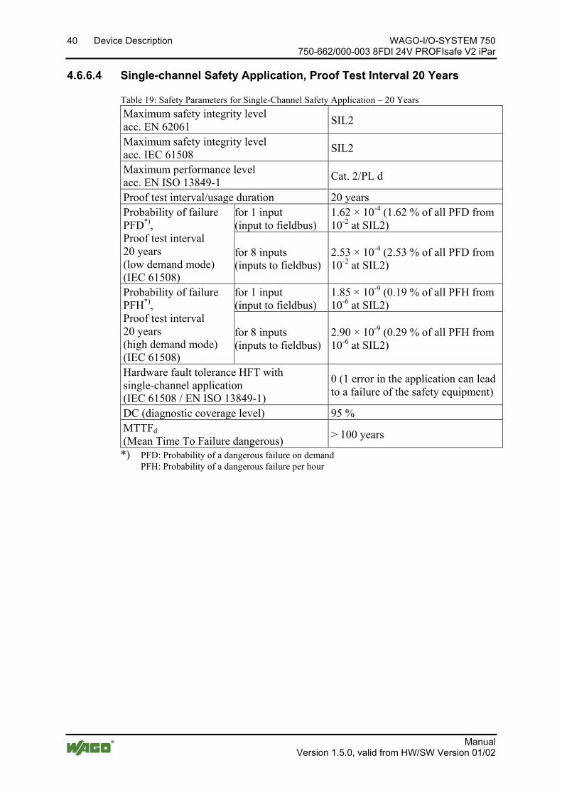
4.6.6.4 Single-channel Safety Application, Proof Test Interval 20 Years
Table 19: Safety Parameters for Single-Channel Safety Application – 20 Years Maximum safety integrity level acc. EN 62061 SIL2
Maximum safety integrity level acc. IEC 61508 SIL2
Maximum performance level acc. EN ISO 13849-1 Cat. 2/PL d
Proof test interval/usage duration 20 years Probability of failure PFD*), Proof test interval 20 years (low demand mode) (IEC 61508)
for 1 input (input to fieldbus)
1.62 × 10⁻⁴ (1.62 % of all PFD from 10-2 at SIL2)
for 8 inputs (inputs to fieldbus)
2.53 × 10⁻⁴ (2.53 % of all PFD from 10-2 at SIL2)
Probability of failure PFH*), Proof test interval 20 years (high demand mode) (IEC 61508)
for 1 input (input to fieldbus)
1.85 × 10⁻⁹ (0.19 % of all PFH from 10-6 at SIL2)
for 8 inputs (inputs to fieldbus)
2.90 × 10⁻⁹ (0.29 % of all PFH from 10-6 at SIL2)
Hardware fault tolerance HFT with single-channel application (IEC 61508 / EN ISO 13849-1)
0 (1 error in the application can lead to a failure of the safety equipment)
DC (diagnostic coverage level) 95 % MTTFd (Mean Time To Failure dangerous) > 100 years
*) PFD: Probability of a dangerous failure on demand PFH: Probability of a dangerous failure per hour
Pos: 24.35 /Dokumentation allgemein/Gliederungselemente/---Seitenwechsel--- @ 3\mod_1221108045078_0.docx @ 21810 @ @ 1
WAGO-I/O-SYSTEM 750 Device Description 41 750-662/000-003 8FDI 24V PROFIsafe V2 iPar
Manual Version 1.5.0, valid from HW/SW Version 01/02
Pos: 24.36.1 /Alle Serien (Allgemeine Module)/Überschriften für alle Serien/Gerätebeschreibung/Anschlusstechnik - Überschrift 3 @ 17\mod_1380123271324_21.docx @ 132788 @ 3 @ 1
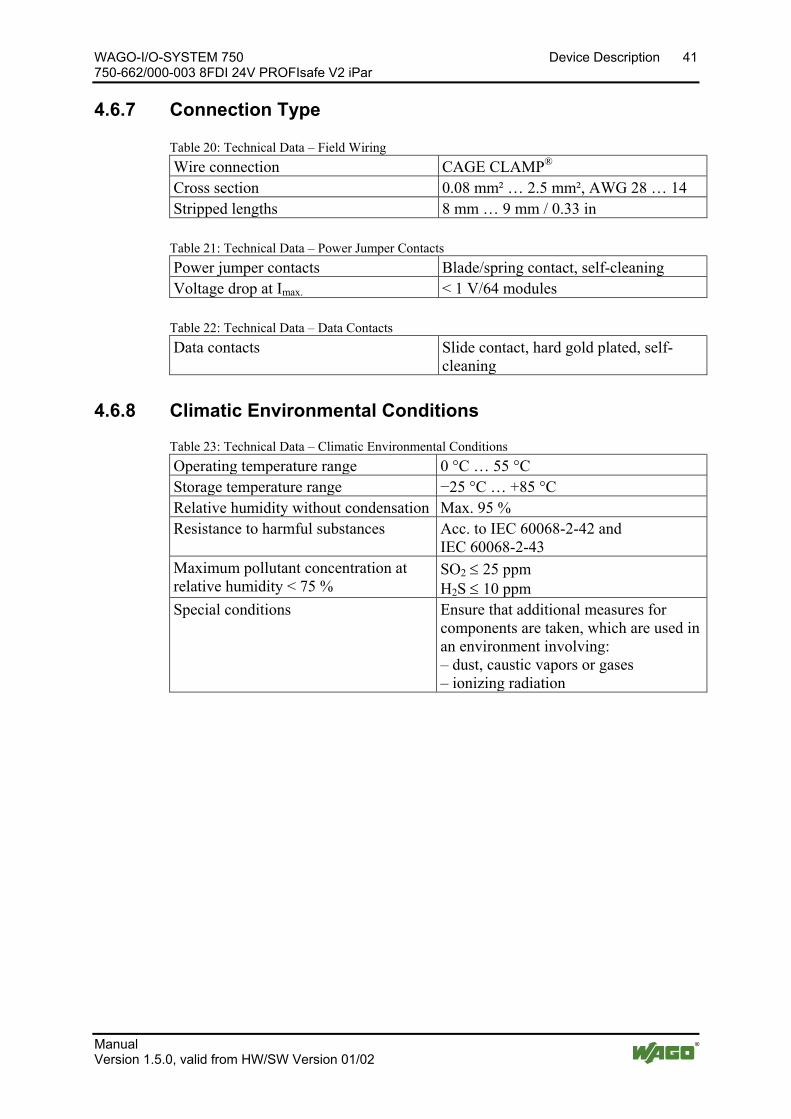
4.6.7 Connection Type Pos: 24.36.2 /Serie 750 (WAGO-I/O-SYSTEM)/Gerätebeschreibung/Technische Daten/Technische Daten Verdrahtungsebene CC - 0,08 bis 2,5mm2 @ 17\mod_1380121238809_21.docx @ 132780 @ @ 1
Table 20: Technical Data – Field Wiring Wire connection CAGE CLAMP® Cross section 0.08 mm² … 2.5 mm², AWG 28 … 14 Stripped lengths 8 mm … 9 mm / 0.33 in
Pos: 24.36.3 /Serie 750 (WAGO-I/O-SYSTEM)/Gerätebeschreibung/Technische Daten/Anschlusstechnik/Technische Daten Leistungskontakte (Messer/Feder) @ 17\mod_1380123464149_21.docx @ 132791 @ @ 1
Table 21: Technical Data – Power Jumper Contacts Power jumper contacts Blade/spring contact, self-cleaning Voltage drop at Imax. < 1 V/64 modules
Pos: 24.36.4 /Serie 750 (WAGO-I/O-SYSTEM)/Gerätebeschreibung/Technische Daten/Anschlusstechnik/Technische Daten Datenkontakte @ 17\mod_1380123495844_21.docx @ 132794 @ @ 1
Table 22: Technical Data – Data Contacts Data contacts Slide contact, hard gold plated, self-
cleaning
Pos: 24.37 /Serie 750 (WAGO-I/O-SYSTEM)/Gerätebeschreibung/Technische Daten/Klimatische Umgebungsbedingungen/Technische Daten Klimat. Umgebungsbed. ohne erw. Temp. 0...55°C/-25...+85°C @ 5\mod_1247657968368_21.docx @ 37603 @ 3 @ 1
4.6.8 Climatic Environmental Conditions
Table 23: Technical Data – Climatic Environmental Conditions Operating temperature range 0 °C … 55 °C Storage temperature range −25 °C … +85 °C Relative humidity without condensation Max. 95 % Resistance to harmful substances Acc. to IEC 60068-2-42 and
IEC 60068-2-43 Maximum pollutant concentration at relative humidity < 75 %
SO2 ≤ 25 ppm H2S ≤ 10 ppm
Special conditions Ensure that additional measures for components are taken, which are used in an environment involving: – dust, caustic vapors or gases – ionizing radiation
Pos: 24.38 /Dokumentation allgemein/Gliederungselemente/---Seitenwechsel--- @ 3\mod_1221108045078_0.docx @ 21810 @ @ 1
42 Device Description WAGO-I/O-SYSTEM 750 750-662/000-003 8FDI 24V PROFIsafe V2 iPar
Manual Version 1.5.0, valid from HW/SW Version 01/02
Pos: 24.39 /Serie 750 (WAGO-I/O-SYSTEM)/Gerätebeschreibung/Technische Daten/Sonstige/PROFIsafe-Reaktionszeiten 75x-066x/000-003 Eingänge @ 7\mod_1268391108976_21.docx @ 52436 @ 344 @ 1
4.6.9 Response Times
4.6.9.1 Safe Response Time of Digital Inputs in the Event of a Failure
Only use response times in the event of a failure for the safety response time! To prevent any personal injury or property damage, only use the values of the safe response time for errors for defining the safety response time.
For the safety response time, take into account the execution times of the internal bus, fieldbus and cycle time of the safe PLC! To prevent any personal injury or property damage, always take the execution times of the internal data bus and of the fieldbus and the cycle time of the safe PLC into account when calculating the safety response time.
The safe response time of the digital inputs indicates the maximum time from a signal change on one single-channel input or two two-channel digital inputs to preparation of the PROFIsafe telegram on the internal bus. It is part of the safety response time of a safety application.
Therefore, take into account the execution times or response times of the safe sensors and actuators used, internal bus, fieldbus, as well as the cycle time of the safe PLC when designing the safety response time.
The safe response time of the digital inputs significantly depends on the configured input filter time. Changing the input filter time changes the safe response time of the digital inputs.
The safe response time can differ depending on the device configuration for each digital input or for the individual input pars (for dual channel evaluation). You can, for example, set the Dual channel evaluation parameter to "yes" and the value of the Valence evaluation to "Equivalent". In this case, the affected input pair has a quicker safe response time than, for example, a single-channel digital input used or if you have set the Valence evaluation parameter to "Antivalent". The safe response times listed in the following table refer to an individual digital input or an individual input par that is analyzed two-channel.
Configuring the PROFIsafe I/O module is described in the section "Parameterization with the WAGO Parameterization Tool".

WAGO-I/O-SYSTEM 750 Device Description 43 750-662/000-003 8FDI 24V PROFIsafe V2 iPar
Manual Version 1.5.0, valid from HW/SW Version 01/02
The following table lists the safe response times in the event of failure that result from the input filter time set.
Table 24: Safe Response Time of the Digital Inputs in the Event of Failure
Input Filter Time
Standard Operating Mode Rotary Table Operating
Mode Single-
Channel Analysis
Valence Evaluation Equivalent
Valence Evaluation Antivalent
0 ms 35 ms 35 ms 19 ms 35 ms 0.5 ms 36 ms 36 ms 20 ms 36 ms 1 ms 38 ms 38 ms 21 ms 38 ms 2 ms 42 ms 42 ms 24 ms 42 ms 3 ms 47 ms 47 ms 28 ms 47 ms 5 ms 59 ms 59 ms 36 ms 59 ms 10 ms 89 ms 89 ms 56 ms 89 ms 20 ms 150 ms 150 ms 96 ms 150 ms 50 ms 331 ms 331 ms 217 ms 331 ms 100 ms 633 ms 633 ms 419 ms 633 ms 200 ms 1237 ms 1237 ms 821 ms 1237 ms

44 Device Description WAGO-I/O-SYSTEM 750 750-662/000-003 8FDI 24V PROFIsafe V2 iPar
Manual Version 1.5.0, valid from HW/SW Version 01/02
4.6.9.2 Typical Response Time of the Digital Inputs in an Error-free Case
Only use response times in the event of a failure for the safety response time! To prevent any personal injury or property damage, only use the values of the safe response time for errors for defining the safety response time (see Section "Safe Response Times for Digital Inputs in the Event of an Error"). Under no circumstances may you use the response times for the digital inputs during error-free operation for the design!
The following table lists the typical response times for the digital inputs in error-free operation. Table 25: Safe Response Time of the Digital Inputs in the Error-Free Operation
Standard Operating Mode Rotary Table Operating
Mode Single-Channel
Analysis
Valence Evaluation Equivalent
Valence Evaluation Antivalent
Signal change 0 1 1 0 0 1 1 0 0 1 1 0 0 1 1 0
Input filter time
0 ms 15 ms 15 ms 15 ms 9 ms 15 ms 9 ms 15 ms 15 ms 0.5 ms 17 ms 17 ms 17 ms 9.5 ms 17 ms 9.5 ms 17 ms 17 ms 1 ms 19 ms 19 ms 19 ms 10 ms 19 ms 10 ms 19 ms 19 ms 2 ms 21 ms 21 ms 21 ms 11 ms 21 ms 11 ms 21 ms 21 ms 3 ms 25 ms 25 ms 25 ms 12 ms 25 ms 12 ms 25 ms 25 ms 5 ms 33 ms 33 ms 33 ms 13 ms 33 ms 13 ms 33 ms 33 ms 10 ms 53 ms 53 ms 53 ms 19 ms 53 ms 19 ms 53 ms 53 ms 20 ms 93 ms 93 ms 93 ms 29 ms 93 ms 29 ms 93 ms 93 ms 50 ms 211 ms 211 ms 211 ms 59 ms 211 ms 59 ms 211 ms 211 ms 100 ms 411 ms 411 ms 411 ms 109 ms 411 ms 109 ms 411 ms 411 ms 200 ms 808 ms 808 ms 808 ms 209 ms 808 ms 209 ms 808 ms 808 ms
Pos: 24.40 /Dokumentation allgemein/Gliederungselemente/---Seitenwechsel--- @ 3\mod_1221108045078_0.docx @ 21810 @ @ 1
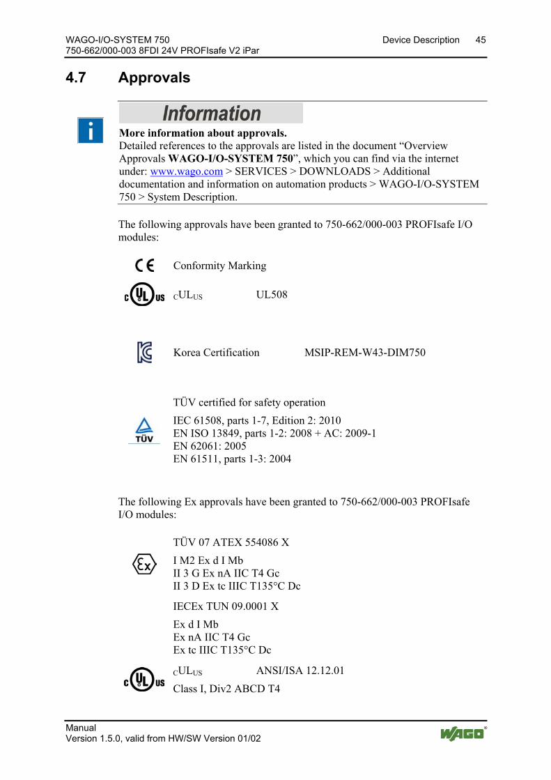
WAGO-I/O-SYSTEM 750 Device Description 45 750-662/000-003 8FDI 24V PROFIsafe V2 iPar
Manual Version 1.5.0, valid from HW/SW Version 01/02
Pos: 24.41 /Alle Serien (Allgemeine Module)/Überschriften für alle Serien/Gerätebeschreibung/Zulassungen - Überschrift 2 @ 3\mod_1224055364109_21.docx @ 24030 @ 2 @ 1
4.7 Approvals Pos: 24.42 /Serie 750 (WAGO-I/O-SYSTEM)/Gerätebeschreibung/Zulassungen/Information: Weitere Informationen zu Zulassungen 750-xxxx @ 3\mod_1227190967156_21.docx @ 25221 @ @ 1
More information about approvals. Detailed references to the approvals are listed in the document “Overview Approvals WAGO-I/O-SYSTEM 750”, which you can find via the internet under: www.wago.com > SERVICES > DOWNLOADS > Additional documentation and information on automation products > WAGO-I/O-SYSTEM 750 > System Description.
Pos: 24.43 /Serie 750 (WAGO-I/O-SYSTEM)/Gerätebeschreibung/Zulassungen/Allgemein/Zulassungen PROFIsafe-Busklemme 75x-066x/xxxx-xxxx Allgemein - Einleitung @ 7\mod_1271745588539_21.docx @ 55440 @ @ 1
The following approvals have been granted to 750-662/000-003 PROFIsafe I/O modules:
Pos: 24.44.1 /Alle Serien (Allgemeine Dokumente) (Allgemeine Module)/Zulassungen/Standardzulassungen/CE (Konformitätskennzeichnung) @ 3\mod_1224494777421_21.docx @ 24276 @ @ 1
Conformity Marking
Pos: 24.44.2 /Alle Serien (Allgemeine Dokumente) (Allgemeine Module)/Zulassungen/Standardzulassungen/cULus (UL508) @ 3\mod_1224055013140_0.docx @ 24020 @ @ 1
CULUS UL508
Pos: 24.44.3 /Dokumentation allgemein/Gliederungselemente/------Leerzeile------ @ 3\mod_1224662755687_0.docx @ 24460 @ @ 1
Pos: 24.45 /Alle Serien (Allgemeine Module)/Zulassungen/Standardzulassungen/KC - Korea Certificate - DI @ 20\mod_1406291677193_21.docx @ 160334 @ @ 1
Korea Certification MSIP-REM-W43-DIM750
Pos: 24.46 /Dokumentation allgemein/Gliederungselemente/------Leerzeile------ @ 3\mod_1224662755687_0.docx @ 24460 @ @ 1
Pos: 24.47 /Alle Serien (Allgemeine Module)/Zulassungen/Standardzulassungen/TÜV-Zertifizierung Einsatz im Sicherheitsbetrieb IEC 61508, EN ISO 13849, EN 62021, EN 61511 @ 13\mod_1348821383383_21.docx @ 103667 @ @ 1
TÜV certified for safety operation IEC 61508, parts 1-7, Edition 2: 2010 EN ISO 13849, parts 1-2: 2008 + AC: 2009-1 EN 62061: 2005 EN 61511, parts 1-3: 2004
Pos: 24.48 /Dokumentation allgemein/Gliederungselemente/------Leerzeile------ @ 3\mod_1224662755687_0.docx @ 24460 @ @ 1
Pos: 24.49 /Serie 750 (WAGO-I/O-SYSTEM)/Gerätebeschreibung/Zulassungen/Ex/Zulassungen PROFIsafe-Busklemme 75x-066x/xxxx-xxxx Ex - Einleitung @ 12\mod_1337156321372_21.docx @ 95114 @ @ 1
The following Ex approvals have been granted to 750-662/000-003 PROFIsafe I/O modules:
Pos: 24.50.1 /Alle Serien (Allgemeine Module)/Zulassungen/Ex-Zulassungen/TÜV ATEX/TÜV 07 ATEX 554086 X: I M2 Ex d I Mb II 3 G Ex nA IIC T4 Gc II 3 D Ex tc IIIC T135°C Dc @ 14\mod_1361949753233_0.docx @ 113015 @ @ 1
TÜV 07 ATEX 554086 X I M2 Ex d I Mb II 3 G Ex nA IIC T4 Gc II 3 D Ex tc IIIC T135°C Dc
Pos: 24.50.2 /Alle Serien (Allgemeine Module)/Zulassungen/Ex-Zulassungen/IECEx (TÜV Nord)/IECEx TUN 09.0001 X: Ex d I Mb Ex nA IIC T4 Gc Ex tc IIIC T135°C @ 14\mod_1361950034299_0.docx @ 113019 @ @ 1
IECEx TUN 09.0001 X Ex d I Mb Ex nA IIC T4 Gc Ex tc IIIC T135°C Dc
Pos: 24.50.3 /Alle Serien (Allgemeine Module)/Zulassungen/Ex-Zulassungen/cULus/cULus (ANSI/ISA 12.12.01) Class I, Div2 ABCD T4 @ 3\mod_1224054791812_0.docx @ 24014 @ @ 1
CULUS ANSI/ISA 12.12.01 Class I, Div2 ABCD T4
Pos: 24.50.4 /Dokumentation allgemein/Gliederungselemente/------Leerzeile------ @ 3\mod_1224662755687_0.docx @ 24460 @ @ 1

46 Device Description WAGO-I/O-SYSTEM 750 750-662/000-003 8FDI 24V PROFIsafe V2 iPar
Manual Version 1.5.0, valid from HW/SW Version 01/02
Pos: 24.51 /Serie 750 (WAGO-I/O-SYSTEM)/Gerätebeschreibung/Zulassungen/Schiff/Zulassungen PROFIsafe-Busklemme 75x-066x/xxxx-xxxx Schiff - Einleitung @ 12\mod_1337156564734_21.docx @ 95128 @ @ 1
The following ship approvals have been granted to 750-662/000-003 PROFIsafe I/O modules:
Pos: 24.52 /Alle Serien (Allgemeine Module)/Zulassungen/Schiffszulassungen/BSH (Bundesamt für Seeschifffahrt und Hydrographie) @ 5\mod_1246341825156_21.docx @ 36334 @ @ 1
Federal Maritime and Hydrographic Agency
Pos: 24.53 /Alle Serien (Allgemeine Module)/Zulassungen/Schiffszulassungen/GL (Germanischer Lloyd) Cat. A, B, C, D (EMC 1) @ 3\mod_1224492724484_0.docx @ 24228 @ @ 1
GL (Germanischer Lloyd) Cat. A, B, C, D (EMC 1)
Pos: 24.54 /Dokumentation allgemein/Gliederungselemente/---Seitenwechsel--- @ 3\mod_1221108045078_0.docx @ 21810 @ @ 1

WAGO-I/O-SYSTEM 750 Device Description 47 750-662/000-003 8FDI 24V PROFIsafe V2 iPar
Manual Version 1.5.0, valid from HW/SW Version 01/02
Pos: 24.55 /Alle Serien (Allgemeine Module)/Überschriften für alle Serien/Gerätebeschreibung/Normen und Richtlinien - Überschrift 2 @ 4\mod_1242804031875_21.docx @ 33646 @ 2 @ 1
4.8 Standards and Guidelines Pos: 24.56 /Serie 750 (WAGO-I/O-SYSTEM)/Gerätebeschreibung/Normen und Richtlinien/Sicherheitsnormen PROFIsafe-Busklemme 75x-066x/xxxx-xxxx - Einleitung @ 7\mod_1265293682755_21.docx @ 49799 @ @ 1
750-662/000-003 PROFIsafe I/O modules meet the following requirements on safety:
Pos: 24.57.1 /Alle Serien (Allgemeine Module)/Normen und Richtlinien/SicherheitsnormenSicherheit DIN EN 61508, Teil 1-7 @ 10\mod_1305787315099_21.docx @ 72983 @ @ 1
Safety of machinery IEC 61508, parts 1-7 Functional safety of electrical/ electronic/ programmable electronic safety-related systems
Pos: 24.57.2 /Alle Serien (Allgemeine Module)/Normen und Richtlinien/SicherheitsnormenSicherheit EN ISO 13849, Teil 1-2 + AC @ 10\mod_1305787552969_21.docx @ 72987 @ @ 1
Safety of machinery – EN ISO 13849, parts 1-2 + AC Safety-related parts of controllers
Pos: 24.57.3 /Alle Serien (Allgemeine Module)/Normen und Richtlinien/SicherheitsnormenSicherheit DIN EN 62061 @ 7\mod_1265293551162_21.docx @ 49791 @ @ 1
Safety of machinery – EN 62061 Functional safety of safety-related electrical/ electronic/ programmable electronic control systems
Pos: 24.57.4 /Alle Serien (Allgemeine Module)/Normen und Richtlinien/Sicherheitsnormen/Funktionale Sicherheit DIN EN 61511-1-3 @ 13\mod_1351071851922_21.docx @ 105280 @ @ 1
Functional safety EN 61511, parts 1-3 Safety instrumented systems for the process industry sector
Pos: 24.58.1 /Alle Serien (Allgemeine Module)/Normen und Richtlinien/EMV-Normen - Standard/EG-EMV-Richtlinie 2004/108/EG @ 7\mod_1274262373820_21.docx @ 56628 @ @ 1
EC EMC Directive 2004/108/EC Pos: 24.58.2 /Alle Serien (Allgemeine Module)/Normen und Richtlinien/EMV-Normen - StandardEMV CE-Störfestigkeit EN 61000-6-2 @ 4\mod_1242797655625_21.docx @ 33591 @ @ 1
EMC CE-Immunity to interference acc. to EN 61000-6-2 Pos: 24.58.3 /Alle Serien (Allgemeine Module)/Normen und Richtlinien/EMV-Normen - StandardEMV CE-Störfestigkeit/-aussendung EN 61131-2 (Ergänzung mit "und") @ 6\mod_1259753131852_21.docx @ 46418 @ @ 1
and acc. to EN 61131-2 Pos: 24.58.4 /Alle Serien (Allgemeine Module)/Normen und Richtlinien/EMV-Normen - StandardEMV CE-Störaussendung EN 61000-6-4 @ 4\mod_1242798273984_21.docx @ 33602 @ @ 1
EMC CE-Emission of interference acc. to EN 61000-6-4 Pos: 24.58.5 /Alle Serien (Allgemeine Module)/Normen und Richtlinien/EMV-Normen - StandardEMV CE-Störfestigkeit/-aussendung EN 61131-2 (Ergänzung mit "und") @ 6\mod_1259753131852_21.docx @ 46418 @ @ 1
and acc. to EN 61131-2 Pos: 24.58.6 /Alle Serien (Allgemeine Module)/Normen und Richtlinien/EMV-Normen - StandardEMV-Anforderungen EN 61326-3-1 @ 7\mod_1265293554521_21.docx @ 49795 @ @ 1
EMC requirements - EN 61326-3-1 Electrical equipment for measurement, control and laboratory use - Immunity requirements for safety-related systems and for equipment intended to perform safety-related functions (functional safety) – General industrial applications
Pos: 24.59 /Dokumentation allgemein/Gliederungselemente/---Seitenwechsel--- @ 3\mod_1221108045078_0.docx @ 21810 @ @ 1

48 Device Description WAGO-I/O-SYSTEM 750 750-662/000-003 8FDI 24V PROFIsafe V2 iPar
Manual Version 1.5.0, valid from HW/SW Version 01/02
Pos: 24.60 /Serie 750 (WAGO-I/O-SYSTEM)/Gerätebeschreibung/Technische Daten/Sonstige/PROFIsafe Transport- und Lagerbedingungen @ 7\mod_1268824364076_21.docx @ 53055 @ 3 @ 1
4.8.1 Transport and Storage Conditions
During transport and storage, the PROFIsafe I/O modules must be protected against undue stress such as mechanical loads, temperature, humidity and aggressive atmospheres.
The PROFIsafe I/O modules should be stored in the original packaging when possible, which offers optimal protection during transport.
When picking or unpacking, do not contaminate or damage the contacts. The PROFIsafe I/O modules must be stored and transported in suitable containers/packaging in compliance with the ESD instructions. The devices contain components sensitive to static discharge and can be damaged by improper handling.
Therefore, when transporting open modules, use statically shielded transport bags with metal coating to prevent contamination from amines, amides and silicones such as 3M 1900E.
In addition, take the required protective measures against electrostatic discharge (ESD) during startup and maintenance of the PROFIsafe I/O modules.
Pos: 24.61 /Serie 750 (WAGO-I/O-SYSTEM)/Wichtige Erläuterungen/Sicherheits- und sonstige Hinweise/Achtung/Achtung: ESD - Auf gute Erdung der Umgebung achten! @ 7\mod_1266318538667_21.docx @ 50708 @ @ 1
Ensure that the environment is well grounded! The devices are equipped with electronic components that may be destroyed by electrostatic discharge. When handling the devices, ensure that the environment (persons, workplace and packing) is well grounded. Avoid touching conductive components, e.g. data contacts.
Pos: 25 /Dokumentation allgemein/Gliederungselemente/---Seitenwechsel--- @ 3\mod_1221108045078_0.docx @ 21810 @ @ 1

WAGO-I/O-SYSTEM 750 Process Image 49 750-662/000-003 8FDI 24V PROFIsafe V2 iPar
Manual Version 1.5.0, valid from HW/SW Version 01/02
Pos: 26 /Alle Serien (Allgemeine Module)/Überschriften für alle Serien/__ noch nicht einsortierte Überschriften müssen noch einsortiert werden __/Prozessabbild - Überschrift 1 @ 4\mod_1240983067828_21.docx @ 31942 @ 1 @ 1
5 Process Image Pos: 27 /Serie 750 (WAGO-I/O-SYSTEM)/Prozessabbild Klemmenbus/Sonderklemmen/Prozessabbild 75x-0662/000-003 @ 6\mod_1265036083890_21.docx @ 49124 @ 22 @ 1
The PROFIsafe I/O module 750-662/000-003 occupies five data bytes in the input and output process image in the higher-level secure PLC. The secure PROFIsafe telegrams to send and receive are stored in input and output bytes 0 … 4.
The process image received different data depending on whether the PROFIsafe I/O module is operated in PROFIsafe V1 or PROFIsafe V2 mode.
5.1 PROFIsafe V1 Mode Table 26: Process Image PROFIsafe V1 Mode
Input data Output data Byte 0 Inputs Byte 0 Reserved Byte 1 Status byte Byte 1 Control byte Byte 2 Serial No. Byte 2 Serial No. Byte 3 CRC16 high byte Byte 3 CRC16 high byte Byte 4 CRC16 low byte Byte 4 CRC16 low byte Byte 0 … byte 4 Secure process data (PROFIsafe telegram) Table 27: PROFIsafe Inputs, V1 Mode
Bit 7 Bit 6 Bit 5 Bit 4 Bit 3 Bit 2 Bit 1 Bit 0 I8 I7 I6 I5 I4 I3 I2 I1
I1 Signal state I1 – Digital input channel 1 I2 Signal state I2 – Digital input channel 2 I3 Signal state I3 – Digital input channel 3 I4 Signal state I4 – Digital input channel 4 I5 Signal state I5 – Digital input channel 5 I6 Signal state I6 – Digital input channel 6 I7 Signal state I7 – Digital input channel 7 I8 Signal state I8 – Digital input channel 8 Table 28: PROFIsafe Outputs, V1 Mode
Bit 7 Bit 6 Bit 5 Bit 4 Bit 3 Bit 2 Bit 1 Bit 0 F_Ack 0 0 0 0 0 0 0
0 Reserved F_Ack Failure_Acknowledge/user acknowledgement for diagnosed failure
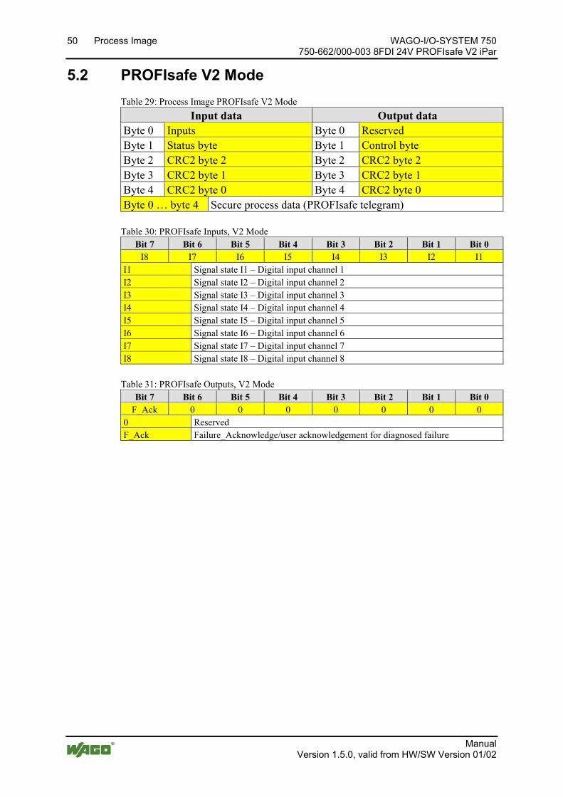
50 Process Image WAGO-I/O-SYSTEM 750 750-662/000-003 8FDI 24V PROFIsafe V2 iPar
Manual Version 1.5.0, valid from HW/SW Version 01/02
5.2 PROFIsafe V2 Mode Table 29: Process Image PROFIsafe V2 Mode
Input data Output data Byte 0 Inputs Byte 0 Reserved Byte 1 Status byte Byte 1 Control byte Byte 2 CRC2 byte 2 Byte 2 CRC2 byte 2 Byte 3 CRC2 byte 1 Byte 3 CRC2 byte 1 Byte 4 CRC2 byte 0 Byte 4 CRC2 byte 0 Byte 0 … byte 4 Secure process data (PROFIsafe telegram) Table 30: PROFIsafe Inputs, V2 Mode
Bit 7 Bit 6 Bit 5 Bit 4 Bit 3 Bit 2 Bit 1 Bit 0 I8 I7 I6 I5 I4 I3 I2 I1
I1 Signal state I1 – Digital input channel 1 I2 Signal state I2 – Digital input channel 2 I3 Signal state I3 – Digital input channel 3 I4 Signal state I4 – Digital input channel 4 I5 Signal state I5 – Digital input channel 5 I6 Signal state I6 – Digital input channel 6 I7 Signal state I7 – Digital input channel 7 I8 Signal state I8 – Digital input channel 8 Table 31: PROFIsafe Outputs, V2 Mode
Bit 7 Bit 6 Bit 5 Bit 4 Bit 3 Bit 2 Bit 1 Bit 0 F_Ack 0 0 0 0 0 0 0
0 Reserved F_Ack Failure_Acknowledge/user acknowledgement for diagnosed failure
Pos: 28 /Dokumentation allgemein/Gliederungselemente/---Seitenwechsel--- @ 3\mod_1221108045078_0.docx @ 21810 @ @ 1
WAGO-I/O-SYSTEM 750 Mounting 51 750-662/000-003 8FDI 24V PROFIsafe V2 iPar
Manual Version 1.5.0, valid from HW/SW Version 01/02
Pos: 29 /Alle Serien (Allgemeine Module)/Überschriften für alle Serien/Montieren/Montieren - Überschrift 1 @ 3\mod_1225446744750_21.docx @ 24900 @ 1 @ 1
6 Mounting Pos: 30.1 /Serie 750 (WAGO-I/O-SYSTEM)/Montieren/Demontieren/Montagereihenfolge @ 3\mod_1231770210031_21.docx @ 25992 @ 2 @ 1
6.1 Mounting Sequence Fieldbus couplers/controllers and I/O modules of the WAGO-I/O-SYSTEM 750/753 are snapped directly on a carrier rail in accordance with the European standard EN 50022 (DIN 35).
The reliable positioning and connection is made using a tongue and groove system. Due to the automatic locking, the individual devices are securely seated on the rail after installation.
Starting with the fieldbus coupler/controller, the I/O modules are mounted adjacent to each other according to the project design. Errors in the design of the node in terms of the potential groups (connection via the power contacts) are recognized, as the I/O modules with power contacts (blade contacts) cannot be linked to I/O modules with fewer power contacts.
Pos: 30.2 /Serie 750 (WAGO-I/O-SYSTEM)/Wichtige Erläuterungen/Sicherheits- und sonstige Hinweise/Vorsicht/Vorsicht: Verletzungsgefahr durch scharfkantige Messerkontakte! @ 6\mod_1256193279401_21.docx @ 43414 @ @ 1
Risk of injury due to sharp-edged blade contacts! The blade contacts are sharp-edged. Handle the I/O module carefully to prevent injury.
Pos: 30.3 /Serie 750 (WAGO-I/O-SYSTEM)/Wichtige Erläuterungen/Sicherheits- und sonstige Hinweise/Achtung/Achtung: Busklemmen nur in vorgesehener Reihenfolge stecken! @ 6\mod_1256194177073_21.docx @ 43429 @ @ 1
Insert I/O modules only from the proper direction! All I/O modules feature grooves for power jumper contacts on the right side. For some I/O modules, the grooves are closed on the top. Therefore, I/O modules featuring a power jumper contact on the left side cannot be snapped from the top. This mechanical coding helps to avoid configuration errors, which may destroy the I/O modules. Therefore, insert I/O modules only from the right and from the top.
Pos: 30.4 /Serie 750 (WAGO-I/O-SYSTEM)/Wichtige Erläuterungen/Sicherheits- und sonstige Hinweise/Hinweis/Hinweis: Busabschluss nicht vergessen! @ 6\mod_1256194225557_21.docx @ 43432 @ @ 1
Don't forget the bus end module! Always plug a bus end module 750-600 onto the end of the fieldbus node! You must always use a bus end module at all fieldbus nodes with WAGO-I/O- SYSTEM 750 fieldbus couplers/controllers to guarantee proper data transfer.
Pos: 30.5 /Dokumentation allgemein/Gliederungselemente/---Seitenwechsel--- @ 3\mod_1221108045078_0.docx @ 21810 @ @ 1
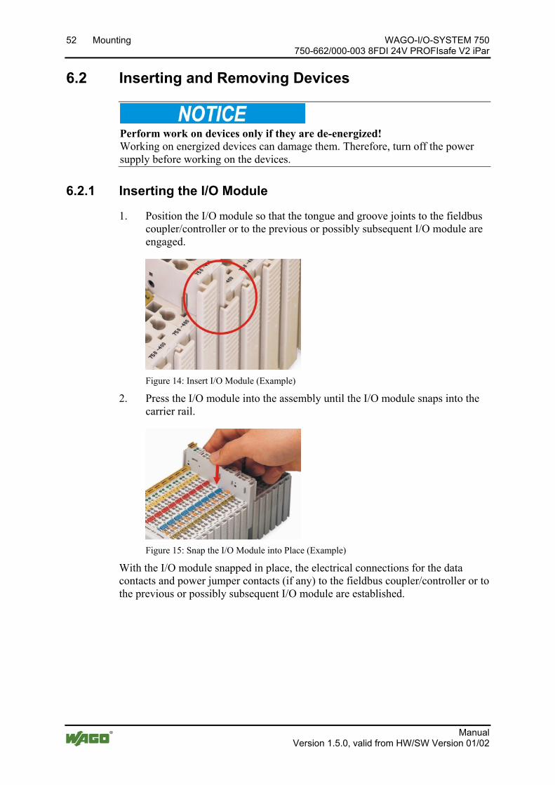
52 Mounting WAGO-I/O-SYSTEM 750 750-662/000-003 8FDI 24V PROFIsafe V2 iPar
Manual Version 1.5.0, valid from HW/SW Version 01/02
Pos: 30.6 /Serie 750 (WAGO-I/O-SYSTEM)/Montieren/Demontieren/Geräte einfügen und entfernen - Überschrift 2 @ 3\mod_1231768483250_21.docx @ 25950 @ 2 @ 1
6.2 Inserting and Removing Devices Pos: 30.7 /Alle Serien (Allgemeine Module)/Wichtige Erläuterungen/Sicherheits- und sonstige Hinweise/Achtung/Achtung: Arbeiten an Geräten nur spannungsfrei durchführen! @ 6\mod_1256193963573_21.docx @ 43426 @ @ 1
Perform work on devices only if they are de-energized! Working on energized devices can damage them. Therefore, turn off the power supply before working on the devices.
Pos: 30.8 /Serie 750 (WAGO-I/O-SYSTEM)/Montieren/Demontieren/Busklemme einfügen @ 3\mod_1231769726703_21.docx @ 25989 @ 3 @ 1
6.2.1 Inserting the I/O Module
1. Position the I/O module so that the tongue and groove joints to the fieldbus coupler/controller or to the previous or possibly subsequent I/O module are engaged.
Figure 14: Insert I/O Module (Example)
2. Press the I/O module into the assembly until the I/O module snaps into the carrier rail.
Figure 15: Snap the I/O Module into Place (Example)
With the I/O module snapped in place, the electrical connections for the data contacts and power jumper contacts (if any) to the fieldbus coupler/controller or to the previous or possibly subsequent I/O module are established.
Pos: 30.9 /Dokumentation allgemein/Gliederungselemente/---Seitenwechsel--- @ 3\mod_1221108045078_0.docx @ 21810 @ @ 1

WAGO-I/O-SYSTEM 750 Mounting 53 750-662/000-003 8FDI 24V PROFIsafe V2 iPar
Manual Version 1.5.0, valid from HW/SW Version 01/02
Pos: 30.10 /Serie 750 (WAGO-I/O-SYSTEM)/Montieren/Demontieren/Busklemme entfernen @ 4\mod_1239169375203_21.docx @ 30334 @ 3 @ 1
6.2.2 Removing the I/O Module
1. Remove the I/O module from the assembly by pulling the release tab.
Figure 16: Removing the I/O Module (Example)
Electrical connections for data or power jumper contacts are disconnected when removing the I/O module.
Pos: 31 /Dokumentation allgemein/Gliederungselemente/---Seitenwechsel--- @ 3\mod_1221108045078_0.docx @ 21810 @ @ 1
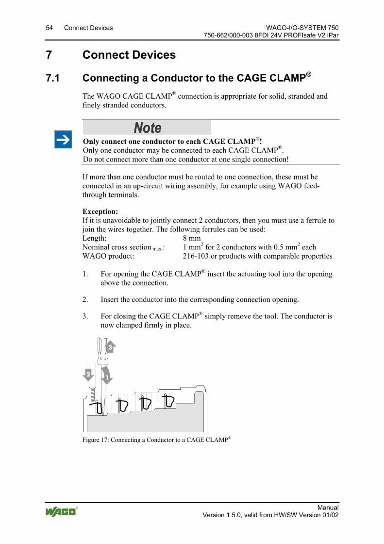
54 Connect Devices WAGO-I/O-SYSTEM 750 750-662/000-003 8FDI 24V PROFIsafe V2 iPar
Manual Version 1.5.0, valid from HW/SW Version 01/02
Pos: 32 /Alle Serien (Allgemeine Module)/Überschriften für alle Serien/Anschließen/Geräte anschließen - Überschrift 1 @ 3\mod_1234172889468_21.docx @ 27460 @ 1 @ 1
7 Connect Devices Pos: 33 /Serie 750 (WAGO-I/O-SYSTEM)/Anschließen/Leiter an CAGE CLAMP anschließen (allgemein) - Überschrift 2 und Text @ 3\mod_1225448660171_21.docx @ 24928 @ 2 @ 1
7.1 Connecting a Conductor to the CAGE CLAMP® The WAGO CAGE CLAMP® connection is appropriate for solid, stranded and finely stranded conductors.
Only connect one conductor to each CAGE CLAMP®! Only one conductor may be connected to each CAGE CLAMP®. Do not connect more than one conductor at one single connection!
If more than one conductor must be routed to one connection, these must be connected in an up-circuit wiring assembly, for example using WAGO feed-through terminals.
Exception: If it is unavoidable to jointly connect 2 conductors, then you must use a ferrule to join the wires together. The following ferrules can be used: Length: 8 mm Nominal cross section max.: 1 mm2 for 2 conductors with 0.5 mm2 each WAGO product: 216-103 or products with comparable properties 1. For opening the CAGE CLAMP® insert the actuating tool into the opening
above the connection.
2. Insert the conductor into the corresponding connection opening.
3. For closing the CAGE CLAMP® simply remove the tool. The conductor is now clamped firmly in place.
Figure 17: Connecting a Conductor to a CAGE CLAMP® Pos: 34 /Dokumentation allgemein/Gliederungselemente/---Seitenwechsel--- @ 3\mod_1221108045078_0.docx @ 21810 @ @ 1
WAGO-I/O-SYSTEM 750 Connect Devices 55 750-662/000-003 8FDI 24V PROFIsafe V2 iPar
Manual Version 1.5.0, valid from HW/SW Version 01/02
Pos: 35 /Alle Serien (Allgemeine Module)/Überschriften für alle Serien/Anschließen/Einspeisekonzept - Überschrift 2 @ 9\mod_1292323902755_21.docx @ 67445 @ 2 @ 1
7.2 Power Supply Concept Pos: 36.1 /Serie 750 (WAGO-I/O-SYSTEM)/Anschließen/Einspeisekonzepte/PROFIsafe-Einspeisekonzept 75x-066x/000-003 @ 6\mod_1265106477572_21.docx @ 49182 @ @ 1
The PROFIsafe I/O module receives the field supply voltage via the power jumper contacts listed as knife blade contacts from an upstream I/O module, the fieldbus coupler/controller or an internal system supply module and makes this potential available via the power jumper contacts listed as spring contacts for downstream I/O modules.
Only operate PROFIsafe I/O modules with safe extra low voltage! When using PROFIsafe I/O modules, only use power supplies with extra-low voltage (PELV/SELV) for the 24 VDC power supply acc. EN 50178 or EN 60950-1. In addition, note that only a maximum voltage of Umax. can act on these modules even in the event of failure. The following applies to all PROFIsafe I/O modules: Umax. < 35 V.
Only operate sensors and actuators with a safe extra low voltage! All sensors and actuators with field supply connected to the PROFIsafe I/O modules also have to be supplied from a safe extra low voltage (SELV/PELV). In the case of error, only the maximum voltage Umax. can be applied to the inputs and outputs of a PROFIsafe I/O module. The following applies to the maximum voltage Umax.: Umax. < 35 V.
Only supply PROFIsafe modules with filtered voltages! Only power a fieldbus node that contains PROFIsafe I/O modules with a voltage filtered against surges (burst and surge) according to EN 61326-3-1. You may need to install an external filter or filter module (750-624 or 750-626). Note that the cable length from the filter to the fieldbus node must be as short as possible.
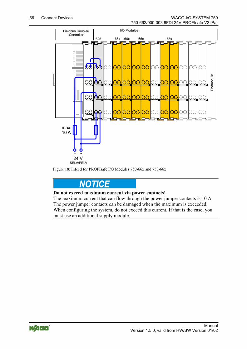
56 Connect Devices WAGO-I/O-SYSTEM 750 750-662/000-003 8FDI 24V PROFIsafe V2 iPar
Manual Version 1.5.0, valid from HW/SW Version 01/02
Figure 18: Infeed for PROFIsafe I/O Modules 750-66x and 753-66x
Do not exceed maximum current via power contacts! The maximum current that can flow through the power jumper contacts is 10 A. The power jumper contacts can be damaged when the maximum is exceeded. When configuring the system, do not exceed this current. If that is the case, you must use an additional supply module.
Pos: 36.2 /Dokumentation allgemein/Gliederungselemente/---Seitenwechsel--- @ 3\mod_1221108045078_0.docx @ 21810 @ @ 1
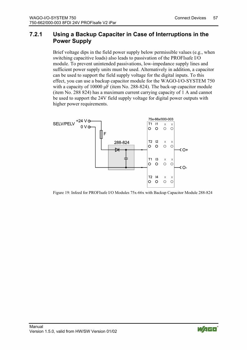
WAGO-I/O-SYSTEM 750 Connect Devices 57 750-662/000-003 8FDI 24V PROFIsafe V2 iPar
Manual Version 1.5.0, valid from HW/SW Version 01/02
Pos: 36.3 /Serie 750 (WAGO-I/O-SYSTEM)/Anschließen/Einspeisekonzepte/PROFIsafe-Einspeisekonzept 75x-661, -662, -666, -667 - Stütz-Elko-Modul @ 23\mod_1441176490483_21.docx @ 190609 @ 3 @ 1
7.2.1 Using a Backup Capaciter in Case of Interruptions in the Power Supply
Brief voltage dips in the field power supply below permissible values (e.g., when switching capacitive loads) also leads to passivation of the PROFIsafe I/O module. To prevent unintended passivations, low-impedance supply lines and sufficient power supply units must be used. Alternatively in addition, a capacitor can be used to support the field supply voltage for the digital inputs. To this effect, you can use a backup capacitor module for the WAGO-I/O-SYSTEM 750 with a capacity of 10000 μF (item No. 288-824). The back-up capacitor module (item No. 288 824) has a maximum current carrying capacity of 1 A and cannot be used to support the 24V field supply voltage for digital power outputs with higher power requirements.
Figure 19: Infeed for PROFIsafe I/O Modules 75x-66x with Backup Capacitor Module 288-824
Pos: 36.4 /Dokumentation allgemein/Gliederungselemente/---Seitenwechsel--- @ 3\mod_1221108045078_0.docx @ 21810 @ @ 1
58 Connect Devices WAGO-I/O-SYSTEM 750 750-662/000-003 8FDI 24V PROFIsafe V2 iPar
Manual Version 1.5.0, valid from HW/SW Version 01/02
Pos: 36.5 /Serie 750 (WAGO-I/O-SYSTEM)/Anschließen/Einspeisekonzepte/PROFIsafe-Einspeisekonzept 230 V 75x-066x/000-003 @ 12\mod_1337669609152_21.docx @ 95351 @ 344 @ 1
7.2.2 Using 230V AC I/O Modules
If 230 VAC I/O modules are used together with PROFIsafe I/O modules in one fieldbus node, there are two options:
7.2.2.1 230V AC Modules are Used in Another Fieldbus Node that Contains no PROFIsafe I/O Modules
You have to use a separate 24 VDC power supply unit (SELV/PELV) for a fieldbus node that contains PROFIsafe I/O modules. You have to use a PELV or FELV power supply unit with protective grounding for a fieldbus node without PROFIsafe I/O modules.
Avoid unacceptably high body voltages! All 230 V AC voltages applied to the nodes must also be protected by a 30 mA residual current circuit breaker.
In the simplest case, place the residual current operated circuit-breaker just behind the junction of the supply network. Doing so allows you to fuse all paths.
Avoid vagabond voltages! Never use a power supply unit to power fieldbus nodes with PROFIsafe I/O modules and fieldbus nodes with 230 V I/O modules.
7.2.2.2 230V AC I/O Modules and PROFIsafe I/O Modules are Used Together
in one Fieldbus Node
An isolation transformer (basic insulation) must be used to supply the voltage for the 230 VAC I/O modules. Between adjoining 230 VAC and 24 VDC I/O modules, you have to take into account the double basic insulation and if necessary, use separation modules 750-616/030-000.
Pos: 37 /Dokumentation allgemein/Gliederungselemente/---Seitenwechsel--- @ 3\mod_1221108045078_0.docx @ 21810 @ @ 1
WAGO-I/O-SYSTEM 750 Connect Devices 59 750-662/000-003 8FDI 24V PROFIsafe V2 iPar
Manual Version 1.5.0, valid from HW/SW Version 01/02
Pos: 38 /Alle Serien (Allgemeine Module)/Überschriften für alle Serien/Anschließen/Anschlussbeispiele - Überschrift 2 @ 4\mod_1240996036328_21.docx @ 32010 @ 2 @ 1
7.3 Connection Examples Pos: 39.1 /Serie 750 (WAGO-I/O-SYSTEM)/Anschließen/Anschlussbeispiele/Sonderklemmen/Anschlussbeispiele 750-066x PROFIsafe/Anschlussbeispiele 750-066x/000-003 Einleitung, Digitale Eingänge Betriebsart "Standard" @ 7\mod_1266335192714_21.docx @ 50826 @ 3 @ 1
Warning against personal and property damage! The use of the connection examples described in this section alone is not enough to execute the safety function according to the SIL, Cat./PL determined from the risk analysis. In connection with safe devices, sensors and actuators, additional measures may be necessary to ensure the safety function. This includes, for example, the appropriate wiring and parameterization of digital inputs and outputs, as well as measures to exclude unforeseeable errors. More information is available in the user manuals of the safe devices used.
The section “Connect Devices” > … > "Connection Examples" generally describes possible applications, in which the functions of the PROFIsafe I/O module for implementation of a safety function are used.
For the digital inputs of the PROFIsafe I/O module, you can use the WAGO parameterization tool during individual parameterization to select the "Standard" or "Rotary table" operating mode. For more information, read the section “Commissioning” > … > "Parameterization of the PROFIsafe I/O Module with the WAGO Parameterization Tool".
Depending on the operating mode of the PROFIsafe I/O module selected, you can operate the following sensors on the digital inputs:
7.3.1 Connection Examples for Digital Inputs in the "Standard" Operating Mode
If you have set the Operating Mode parameter of the PROFIsafe I/O module to "Standard" using the WAGO parameterization tool, you can operate the inputs of the PROFIsafe I/O module single- or two-channel.
Connection examples for the "Standard" operating mode are further examined below.
Pos: 39.2 /Serie 750 (WAGO-I/O-SYSTEM)/Anschließen/Anschlussbeispiele/Sonderklemmen/Anschlussbeispiele 750-066x PROFIsafe/Anschlussbeispiel 750-066x/000-003 Not-Aus, einkanalig, Überschrift 4 + Warnung @ 7\mod_1269863045886_21.docx @ 54626 @ 4 @ 1
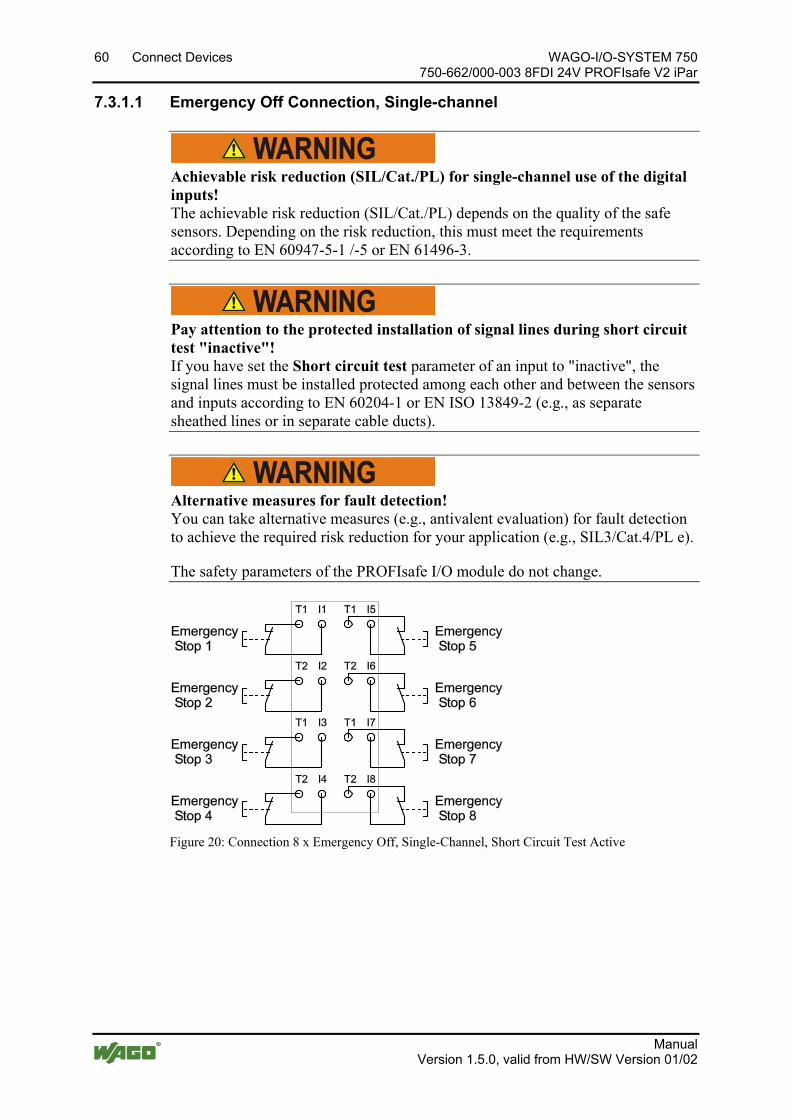
60 Connect Devices WAGO-I/O-SYSTEM 750 750-662/000-003 8FDI 24V PROFIsafe V2 iPar
Manual Version 1.5.0, valid from HW/SW Version 01/02
7.3.1.1 Emergency Off Connection, Single-channel
Achievable risk reduction (SIL/Cat./PL) for single-channel use of the digital inputs! The achievable risk reduction (SIL/Cat./PL) depends on the quality of the safe sensors. Depending on the risk reduction, this must meet the requirements according to EN 60947-5-1 /-5 or EN 61496-3.
Pos: 39.3 /Serie 750 (WAGO-I/O-SYSTEM)/Anschließen/Anschlussbeispiele/Sonderklemmen/Anschlussbeispiele 750-066x PROFIsafe/Anschlussbeispiele 750-066x/000-003 Warnung: Geschützte Verlegung bei Kurzschlusst. „nicht aktiv“ be @ 7\mod_1267016745817_21.docx @ 51400 @ @ 1
Pay attention to the protected installation of signal lines during short circuit test "inactive"! If you have set the Short circuit test parameter of an input to "inactive", the signal lines must be installed protected among each other and between the sensors and inputs according to EN 60204-1 or EN ISO 13849-2 (e.g., as separate sheathed lines or in separate cable ducts).
Pos: 39.4 /Serie 750 (WAGO-I/O-SYSTEM)/Anschließen/Anschlussbeispiele/Sonderklemmen/Anschlussbeispiele 750-066x PROFIsafe/Anschlussbeispiele 750-066x/000-003 Warnung: Alternative Maßnahmen zur Fehleraufdeckung @ 23\mod_1439813218651_21.docx @ 189528 @ @ 1
Alternative measures for fault detection! You can take alternative measures (e.g., antivalent evaluation) for fault detection to achieve the required risk reduction for your application (e.g., SIL3/Cat.4/PL e).
The safety parameters of the PROFIsafe I/O module do not change.
Pos: 39.5 /Serie 750 (WAGO-I/O-SYSTEM)/Anschließen/Anschlussbeispiele/Sonderklemmen/Anschlussbeispiele 750-066x PROFIsafe/Anschlussbeispiel 750-0662/000-003 Bild 8 x Not-Aus, einkanalig @ 7\mod_1266331475370_21.docx @ 50790 @ @ 1
Figure 20: Connection 8 x Emergency Off, Single-Channel, Short Circuit Test Active
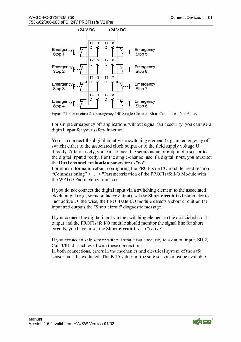
WAGO-I/O-SYSTEM 750 Connect Devices 61 750-662/000-003 8FDI 24V PROFIsafe V2 iPar
Manual Version 1.5.0, valid from HW/SW Version 01/02
Figure 21: Connection 8 x Emergency Off, Single-Channel, Short Circuit Test Not Active Pos: 39.6 /Serie 750 (WAGO-I/O-SYSTEM)/Anschließen/Anschlussbeispiele/Sonderklemmen/Anschlussbeispiele 750-066x PROFIsafe/Anschlussbeispiel 750-066x/000-003 Text Not-Aus, einkanalig @ 7\mod_1269940848219_21.docx @ 54698 @ @ 1
For simple emergency off applications without signal fault security, you can use a digital input for your safety function.
You can connect the digital input via a switching element (e.g., an emergency off switch) either to the associated clock output or to the field supply voltage Uv directly. Alternatively, you can connect the semiconductor output of a sensor to the digital input directly. For the single-channel use if a digital input, you must set the Dual channel evaluation parameter to "no". For more information about configuring the PROFIsafe I/O module, read section “Commissioning” > … > "Parameterization of the PROFIsafe I/O Module with the WAGO Parameterization Tool".
If you do not connect the digital input via a switching element to the associated clock output (e.g., semiconductor output), set the Short circuit test parameter to "not active". Otherwise, the PROFIsafe I/O module detects a short circuit on the input and outputs the "Short circuit" diagnostic message.
If you connect the digital input via the switching element to the associated clock output and the PROFIsafe I/O module should monitor the signal line for short circuits, you have to set the Short circuit test to "active". If you connect a safe sensor without single fault security to a digital input, SIL2, Cat. 3/PL d is achieved with these connections. In both connections, errors in the mechanics and electrical system of the safe sensor must be excluded. The B 10 values of the safe sensors must be available.
Pos: 39.7 /Serie 750 (WAGO-I/O-SYSTEM)/Anschließen/Anschlussbeispiele/Sonderklemmen/Anschlussbeispiele 750-066x PROFIsafe/Anschlussbeispiel 750-066x/000-003 Not-Aus, zweikanalig, Überschrift 4 @ 7\mod_1269866694327_21.docx @ 54629 @ 4 @ 1
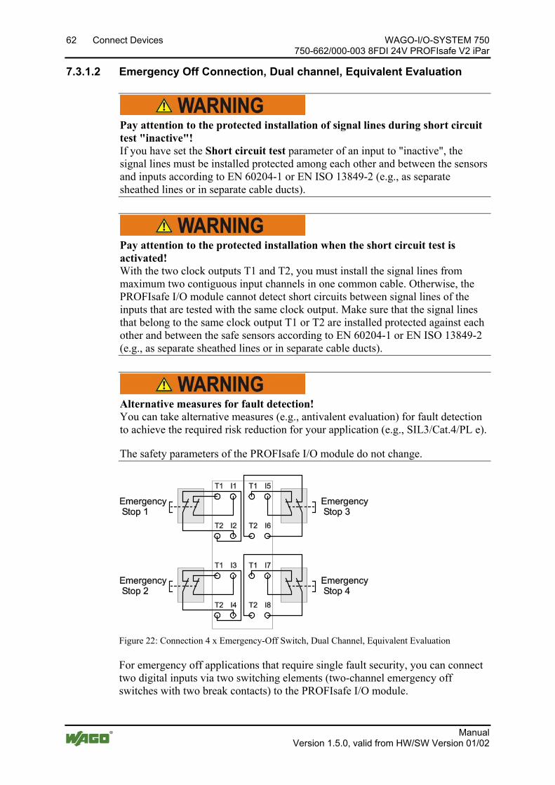
62 Connect Devices WAGO-I/O-SYSTEM 750 750-662/000-003 8FDI 24V PROFIsafe V2 iPar
Manual Version 1.5.0, valid from HW/SW Version 01/02
7.3.1.2 Emergency Off Connection, Dual channel, Equivalent Evaluation Pos: 39.8 /Serie 750 (WAGO-I/O-SYSTEM)/Anschließen/Anschlussbeispiele/Sonderklemmen/Anschlussbeispiele 750-066x PROFIsafe/Anschlussbeispiele 750-066x/000-003 Warnung: Geschützte Verlegung bei Kurzschlusst. „nicht aktiv“ be @ 7\mod_1267016745817_21.docx @ 51400 @ @ 1
Pay attention to the protected installation of signal lines during short circuit test "inactive"! If you have set the Short circuit test parameter of an input to "inactive", the signal lines must be installed protected among each other and between the sensors and inputs according to EN 60204-1 or EN ISO 13849-2 (e.g., as separate sheathed lines or in separate cable ducts).
Pos: 39.9 /Serie 750 (WAGO-I/O-SYSTEM)/Anschließen/Anschlussbeispiele/Sonderklemmen/Anschlussbeispiele 750-066x PROFIsafe/Anschlussbeispiele 750-066x/000-003 Warnung: Geschützte Verlegung bei aktiviertem Kurzschlusstest! @ 7\mod_1267016960910_21.docx @ 51403 @ @ 1
Pay attention to the protected installation when the short circuit test is activated! With the two clock outputs T1 and T2, you must install the signal lines from maximum two contiguous input channels in one common cable. Otherwise, the PROFIsafe I/O module cannot detect short circuits between signal lines of the inputs that are tested with the same clock output. Make sure that the signal lines that belong to the same clock output T1 or T2 are installed protected against each other and between the safe sensors according to EN 60204-1 or EN ISO 13849-2 (e.g., as separate sheathed lines or in separate cable ducts).
Pos: 39.10 /Serie 750 (WAGO-I/O-SYSTEM)/Anschließen/Anschlussbeispiele/Sonderklemmen/Anschlussbeispiele 750-066x PROFIsafe/Anschlussbeispiele 750-066x/000-003 Warnung: Alternative Maßnahmen zur Fehleraufdeckung @ 23\mod_1439813218651_21.docx @ 189528 @ @ 1
Alternative measures for fault detection! You can take alternative measures (e.g., antivalent evaluation) for fault detection to achieve the required risk reduction for your application (e.g., SIL3/Cat.4/PL e).
The safety parameters of the PROFIsafe I/O module do not change.
Pos: 39.11 /Serie 750 (WAGO-I/O-SYSTEM)/Anschließen/Anschlussbeispiele/Sonderklemmen/Anschlussbeispiele 750-066x PROFIsafe/Anschlussbeispiel 750-0662/000-003 Bild 4 x Not-Aus, zweikanalig @ 7\mod_1266331323667_21.docx @ 50778 @ @ 1
Figure 22: Connection 4 x Emergency-Off Switch, Dual Channel, Equivalent Evaluation Pos: 39.12 /Serie 750 (WAGO-I/O-SYSTEM)/Anschließen/Anschlussbeispiele/Sonderklemmen/Anschlussbeispiele 750-066x PROFIsafe/Anschlussbeispiel 750-066x/000-003 Text Not-Aus, zweikanalig @ 7\mod_1269942078421_21.docx @ 54702 @ @ 1
For emergency off applications that require single fault security, you can connect two digital inputs via two switching elements (two-channel emergency off switches with two break contacts) to the PROFIsafe I/O module.
WAGO-I/O-SYSTEM 750 Connect Devices 63 750-662/000-003 8FDI 24V PROFIsafe V2 iPar
Manual Version 1.5.0, valid from HW/SW Version 01/02
Use the WAGO parameterization tool to set the parameters. For more information about configuring the PROFIsafe I/O module, read section "Parameterization of the PROFIsafe I/O Module with the WAGO Parameterization Tool".
Set the Dual channel evaluation parameter to "yes" for the digital inputs used and the Valence evaluation parameter to "equivalent". In addition, set the Discrepancy time parameter to the discrepancy time required for the two switching elements.
You can set the Short circuit test parameter of both inputs used to "active" or "not active". Please note that the Short circuit test parameter must be set the same for both digital inputs.
Pos: 39.13 /Serie 750 (WAGO-I/O-SYSTEM)/Anschließen/Anschlussbeispiele/Sonderklemmen/Anschlussbeispiele 750-066x PROFIsafe/Anschlussbeispiel 750-066x/000-003 Text Not-Aus, zweikanalig - Ergänzung +24 V und Halbleiter @ 13\mod_1353572908897_21.docx @ 106778 @ @ 1
If you connect the digital inputs via the switching elements directly to the field voltage of _24 V or to two semiconductor outputs of a sensor, then you have to set the Short circuit test parameter to "not active" because otherwise the PROFIsafe I/O module detects a short circuit and outputs the "Short circuit" diagnostic message.
Pos: 39.14 /Dokumentation allgemein/Gliederungselemente/---Seitenwechsel--- @ 3\mod_1221108045078_0.docx @ 21810 @ @ 1
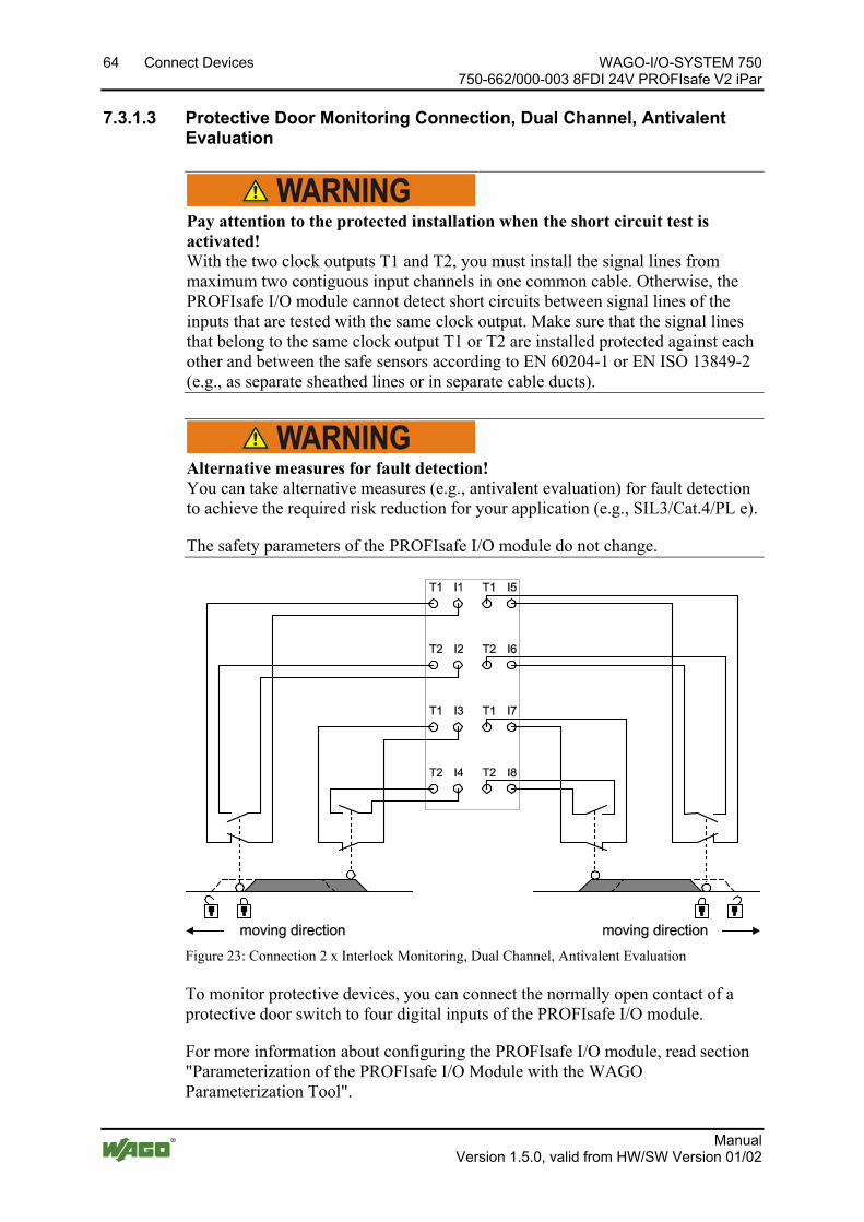
64 Connect Devices WAGO-I/O-SYSTEM 750 750-662/000-003 8FDI 24V PROFIsafe V2 iPar
Manual Version 1.5.0, valid from HW/SW Version 01/02
Pos: 39.15 /Serie 750 (WAGO-I/O-SYSTEM)/Anschließen/Anschlussbeispiele/Sonderklemmen/Anschlussbeispiele 750-066x PROFIsafe/Anschlussbeispiel 750-066x/000-003 Schutztürüberwachung, zweikanalig, Überschrift 4 @ 7\mod_1269874909806_21.docx @ 54633 @ 4 @ 1
7.3.1.3 Protective Door Monitoring Connection, Dual Channel, Antivalent Evaluation
Pos: 39.16 /Serie 750 (WAGO-I/O-SYSTEM)/Anschließen/Anschlussbeispiele/Sonderklemmen/Anschlussbeispiele 750-066x PROFIsafe/Anschlussbeispiele 750-066x/000-003 Warnung: Geschützte Verlegung bei aktiviertem Kurzschlusstest! @ 7\mod_1267016960910_21.docx @ 51403 @ @ 1
Pay attention to the protected installation when the short circuit test is activated! With the two clock outputs T1 and T2, you must install the signal lines from maximum two contiguous input channels in one common cable. Otherwise, the PROFIsafe I/O module cannot detect short circuits between signal lines of the inputs that are tested with the same clock output. Make sure that the signal lines that belong to the same clock output T1 or T2 are installed protected against each other and between the safe sensors according to EN 60204-1 or EN ISO 13849-2 (e.g., as separate sheathed lines or in separate cable ducts).
Pos: 39.17 /Serie 750 (WAGO-I/O-SYSTEM)/Anschließen/Anschlussbeispiele/Sonderklemmen/Anschlussbeispiele 750-066x PROFIsafe/Anschlussbeispiele 750-066x/000-003 Warnung: Alternative Maßnahmen zur Fehleraufdeckung @ 23\mod_1439813218651_21.docx @ 189528 @ @ 1
Alternative measures for fault detection! You can take alternative measures (e.g., antivalent evaluation) for fault detection to achieve the required risk reduction for your application (e.g., SIL3/Cat.4/PL e).
The safety parameters of the PROFIsafe I/O module do not change.
Pos: 39.18 /Serie 750 (WAGO-I/O-SYSTEM)/Anschließen/Anschlussbeispiele/Sonderklemmen/Anschlussbeispiele 750-066x PROFIsafe/Anschlussbeispiel 750-0662/000-003 Bild 2 x Schutztürüberwachung @ 7\mod_1266332653058_21.docx @ 50806 @ @ 1
Figure 23: Connection 2 x Interlock Monitoring, Dual Channel, Antivalent Evaluation Pos: 39.19 /Serie 750 (WAGO-I/O-SYSTEM)/Anschließen/Anschlussbeispiele/Sonderklemmen/Anschlussbeispiele 750-066x PROFIsafe/Anschlussbeispiel 750-066x/000-003 Text Schutztürüberwachung, zweikanalig @ 7\mod_1269942433232_21.docx @ 54706 @ @ 1
To monitor protective devices, you can connect the normally open contact of a protective door switch to four digital inputs of the PROFIsafe I/O module.
For more information about configuring the PROFIsafe I/O module, read section "Parameterization of the PROFIsafe I/O Module with the WAGO Parameterization Tool".
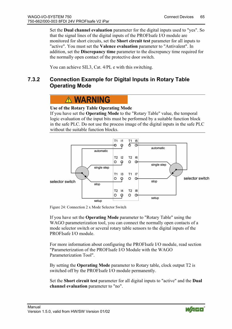
WAGO-I/O-SYSTEM 750 Connect Devices 65 750-662/000-003 8FDI 24V PROFIsafe V2 iPar
Manual Version 1.5.0, valid from HW/SW Version 01/02
Set the Dual channel evaluation parameter for the digital inputs used to "yes". So that the signal lines of the digital inputs of the PROFIsafe I/O module are monitored for short circuits, set the Short circuit test parameter for all inputs to "active". You must set the Valence evaluation parameter to "Antivalent". In addition, set the Discrepancy time parameter to the discrepancy time required for the normally open contact of the protective door switch.
You can achieve SIL3, Cat. 4/PL e with this switching. Pos: 39.20 /Serie 750 (WAGO-I/O-SYSTEM)/Anschließen/Anschlussbeispiele/Sonderklemmen/Anschlussbeispiele 750-066x PROFIsafe/Anschlussbeispiel 750-066x/000-003 Digitale Eingänge Betriebsart Rundtisch, Überschrift 4 + Hinweis @ 7\mod_1269875881290_21.docx @ 54637 @ 3 @ 1
7.3.2 Connection Example for Digital Inputs in Rotary Table Operating Mode
Use of the Rotary Table Operating Mode If you have set the Operating Mode to the "Rotary Table" value, the temporal logic evaluation of the input bits must be performed by a suitable function block in the safe PLC. Do not use the process image of the digital inputs in the safe PLC without the suitable function blocks.
Pos: 39.21 /Serie 750 (WAGO-I/O-SYSTEM)/Anschließen/Anschlussbeispiele/Sonderklemmen/Anschlussbeispiele 750-066x PROFIsafe/Anschlussbeispiel 750-0662/000-003 Bild 2 x Betriebsarten-Wahlschalter @ 7\mod_1266390773371_21.docx @ 50914 @ @ 1
Figure 24: Connection 2 x Mode Selector Switch Pos: 39.22 /Serie 750 (WAGO-I/O-SYSTEM)/Anschließen/Anschlussbeispiele/Sonderklemmen/Anschlussbeispiele 750-066x PROFIsafe/Anschlussbeispiel 750-066x/000-003 Text Digitale Eingänge in Betriebsart Rundtisch @ 7\mod_1269943301716_21.docx @ 54714 @ @ 1
If you have set the Operating Mode parameter to "Rotary Table" using the WAGO parameterization tool, you can connect the normally open contacts of a mode selector switch or several rotary table sensors to the digital inputs of the PROFIsafe I/O module. For more information about configuring the PROFIsafe I/O module, read section "Parameterization of the PROFIsafe I/O Module with the WAGO Parameterization Tool".
By setting the Operating Mode parameter to Rotary table, clock output T2 is switched off by the PROFIsafe I/O module permanently.
Set the Short circuit test parameter for all digital inputs to "active" and the Dual channel evaluation parameter to "no".
66 Connect Devices WAGO-I/O-SYSTEM 750 750-662/000-003 8FDI 24V PROFIsafe V2 iPar
Manual Version 1.5.0, valid from HW/SW Version 01/02
Then connect the normally open contacts of the mode selector switch to the digital inputs and the common clock line of the mode selector switch to clock output T1. The process image of the digital inputs now contains the switch setting of the mode selector switch.
A suitable module must be used in the safety application of the safe PLC to analyze the input bits. Details about a suitable module are available in an application note.
Use the application notes from WAGO! An overview for using PROFIsafe I/O modules in combination with a safe PLC is summarized in an application note. This application note is available on the Internet at www.wago.com in the area "Service > Documentation > Application Notes...".
Pos: 40 /Dokumentation allgemein/Gliederungselemente/---Seitenwechsel--- @ 3\mod_1221108045078_0.docx @ 21810 @ @ 1
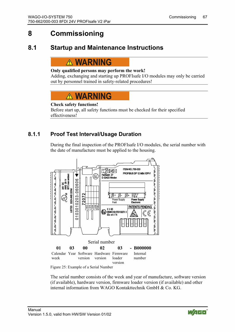
WAGO-I/O-SYSTEM 750 Commissioning 67 750-662/000-003 8FDI 24V PROFIsafe V2 iPar
Manual Version 1.5.0, valid from HW/SW Version 01/02
Pos: 41 /Alle Serien (Allgemeine Module)/Überschriften für alle Serien/Inbetriebnehmen - Konfigurieren - Parametrieren - Bedienen/In Betrieb nehmen - Überschrift 1 @ 4\mod_1240901452750_21.docx @ 31570 @ 1 @ 1
8 Commissioning Pos: 42 /Serie 750 (WAGO-I/O-SYSTEM)/In Betrieb nehmen/PROFIsafe in Betrieb nehmen/PROFIsafe Inbetriebnahme- und Wartungshinweise - Überschrift 2 und Hinweise @ 4\mod_1235471757078_21.docx @ 27666 @ 2 @ 1
8.1 Startup and Maintenance Instructions
Only qualified persons may perform the work! Adding, exchanging and starting up PROFIsafe I/O modules may only be carried out by personnel trained in safety-related procedures!
Check safety functions! Before start up, all safety functions must be checked for their specified effectiveness!
Pos: 43.1 /Serie 750 (WAGO-I/O-SYSTEM)/Service/PROFIsafe/PROFIsafe Prooftest-Intervall/Gebrauchsdauer 750-066x/000-003 Überschrift 3 und Einleitung @ 10\mod_1301638248831_21.docx @ 71461 @ 3 @ 1
8.1.1 Proof Test Interval/Usage Duration
During the final inspection of the PROFIsafe I/O modules, the serial number with the date of manufacture must be applied to the housing.
Pos: 43.2 /Serie 750 (WAGO-I/O-SYSTEM)/Gerätebeschreibung/Bedruckung/Fertigungsnummer 750-xxxx @ 10\mod_1301639785385_21.docx @ 71474 @ @ 1
Serial number 01 03 00 02 03 - B000000
Calendar week
Year Software version
Hardware version
Firmware loader version
Internal number
Figure 25: Example of a Serial Number
The serial number consists of the week and year of manufacture, software version (if available), hardware version, firmware loader version (if available) and other internal information from WAGO Kontakttechnik GmbH & Co. KG.
Pos: 43.3 /Serie 750 (WAGO-I/O-SYSTEM)/Service/PROFIsafe/PROFIsafe Prooftest 750-066x/000-003 Allgemein @ 10\mod_1301636231132_21.docx @ 71450 @ @ 1
68 Commissioning WAGO-I/O-SYSTEM 750 750-662/000-003 8FDI 24V PROFIsafe V2 iPar
Manual Version 1.5.0, valid from HW/SW Version 01/02
The date of manufacture (calendar week/year) marks the beginning of the proof test interval.
The proof test interval is specified in the technical data of the respective PROFIsafe I/O module.
Pos: 43.4 /Serie 750 (WAGO-I/O-SYSTEM)/Service/PROFIsafe/PROFIsafe Prooftest 75x-066x/000-003 Text Ende der Gebrauchsdauer @ 23\mod_1437393018334_21.docx @ 186498 @ @ 1
At the end of the proof test interval, the usage duration of the PROFIsafe I/O module is also reached. The PROFIsafe I/O module must then be replaced.
Pos: 44 /Serie 750 (WAGO-I/O-SYSTEM)/In Betrieb nehmen/PROFIsafe in Betrieb nehmen/PROFIsafe Hinzufügen und Austauschen von Komponenten @ 7\mod_1272289792546_21.docx @ 55674 @ 3 @ 1
8.1.2 Adding or Replacing Components
If PROFIsafe I/O modules are added to a fieldbus node (see section "Inserting and Removing Devices") or replaced (see section "Replacing PROFIsafe I/O Modules"), the associated safety function should undergo additional testing before starting up the machine or system.
Pos: 45 /Serie 750 (WAGO-I/O-SYSTEM)/In Betrieb nehmen/PROFIsafe in Betrieb nehmen/PROFIsafe-Adresse einstellen 75x-066x/000-003 @ 6\mod_1265039936312_21.docx @ 49153 @ 233 @ 1
8.2 Setting the PROFIsafe Address The PROFIsafe address can be set by the coding switch of the I/O module or by the WAGO parameterization tool. The PROFIsafe address set on the coding switch of the I/O module has priority over the PROFIsafe address set by the WAGO parameterization tool. Only when the address set on the coding switch equals 0 does the setting of the PROFIsafe address using the WAGO parameterization tool take effect.
Default status address setting In the default status, the address setting by the coding switch is active.
WAGO-I/O-SYSTEM 750 Commissioning 69 750-662/000-003 8FDI 24V PROFIsafe V2 iPar
Manual Version 1.5.0, valid from HW/SW Version 01/02
8.2.1 Setting the PROFIsafe Address using the Coding Switch
Disconnect the power from the node before making the settings! Switch off the fieldbus node before you pull the PROFIsafe I/O module out of the fieldbus node to change the settings!
Use only appropriate tools to change the settings! To set the switching elements of the coding switch, use only suitable objects (e.g., test prod or watchmakers screwdriver). Never exert pressure on the switching elements.
Coding switch is inaccessible when the I/O module is plugged in! To set the PROFIsafe address on the coding switch, the I/O module must be pulled out of the fieldbus node.
Use the switching elements of the coding switch to set the PROFIsafe address to a value from 1 to 1023.
8.2.2 Setting the PROFIsafe Address using the WAGO Parameterization Tool
Effectiveness using the WAGO Parameterization Tool The PROFIsafe address set using the WAGO parameterization tool only takes effect when the address set on the coding switch of the I/O module equals 0.
To configure the PROFIsafe address through storage in the parameter data set of the I/O module, set the PROFIsafe address in the WAGO parameterization tool to the required value and save the current parameter data set to the I/O module.
Configuring the PROFIsafe I/O module is described in the section "Parameterization with the WAGO Parameterization Tool".
Pos: 46 /Dokumentation allgemein/Gliederungselemente/---Seitenwechsel--- @ 3\mod_1221108045078_0.docx @ 21810 @ @ 1
70 Commissioning WAGO-I/O-SYSTEM 750 750-662/000-003 8FDI 24V PROFIsafe V2 iPar
Manual Version 1.5.0, valid from HW/SW Version 01/02
Pos: 47.1 /Serie 750 (WAGO-I/O-SYSTEM)/In Betrieb nehmen/Parametrieren mit WAGO-I/O-CHECK/Parametrieren 750-66x/Parametrierung 75x-066x mit WAGO-I/O-CHECK 3.2 @ 5\mod_1246888298921_21.docx @ 36694 @ 233 @ 1
8.3 Parameterization of the PROFIsafe I/O Module with the WAGO Parameterization Tool
Only qualified persons may perform these tasks! Adding, exchanging and starting up PROFIsafe I/O modules may only be carried out by personnel trained in safety-related procedures!
Check safety functions! Before start up, all safety functions must be checked for their specified effectiveness!
Only operate PROFIsafe I/O modules with active password protection! Without using the iPar functionality, PROFIsafe I/O modules may only be operated in safety-related applications with active password protection. PROFIsafe I/O modules may be operated in safety-related applications without active password protection if the PROFIsafe I/O module is operated with iPar functionality (see the "PROFIsafe I/O Module with iPar Functionality without iPar Server" section).
The WAGO Safety Editor 75x 2.x can be started with different call options. Depending on the call option, the Safety Editor is started in either ONLINE or OFFLINE mode.
ONLINE mode is used to change the parameter data of a PROFIsafe I/O module directly.
OFFLINE mode is used to create or change parameter data of a PROFIsafe I/O module in a parameter file.
8.3.1 ONLINE Mode
When opening the Safety Editor, the current parameter set of the PROFIsafe I/O module is read from permanent memory and displayed in the Input column of the parameter table in the Safety Editor.
If you want to access existing parameter files, click on the [Open] button on the Safety Editor toolbar.
In the Open WAGO safety parameter set dialog, enter a name for the parameter file and select the directory from which the file is to be loaded. Now click on [Open] in order to load the file from the hard disk.
WAGO-I/O-SYSTEM 750 Commissioning 71 750-662/000-003 8FDI 24V PROFIsafe V2 iPar
Manual Version 1.5.0, valid from HW/SW Version 01/02
Another iParameter set description dialog opens. In this dialog, verify the information given on the project, on the changes made, and on the personnel in charge and change the information if need be. Click [OK] to confirm.
In the Input column of the parameter table, you can now make the desired changes to the parameter values.
If you click on a parameter value with the left mouse button, depending on the parameter you have selected, either a selection list of the possible settings for this parameter will be displayed or you can enter the desired value directly.
A changed parameter value is marked with a pen symbol, which is displayed in the first column of the parameter table.
After changing the parameter values, transfer them into the I/O module. To do so, click on [WRITE] in the Safety Editor toolbar.
If you have assigned a password for the I/O module, you will now be asked to enter it. After entering the password, the parameter values are transmitted and verified by the I/O module.
The verified parameter values are then read out of the I/O module and displayed in the Verification column of the parameter table.
Now compare the parameter values of the "Input" column with the values of the "Verification" column line by line. If the values are identical, mark the line as verified by activating the checkbox on the right side next to the Verification column.
As soon as all lines have been verified (all checkboxes are activated), the checkbox in the headline of the column is activated automatically.
Now save the new parameter values permanently in the I/O module by clicking the [Save] button on the Safety Editor toolbar.
The I/O module now permanently stores the parameter values in the PROFIsafe I/O module. The values are then read out once again and displayed in the Input column of the parameter table for another check.
If all settings are correct, save the parameter set in a parameter file. To do so, click [Save] in the Safety Editor toolbar.
The iParameter set description dialog opens for the detailed description of the parameter file. In this dialog, enter information about the project, the changes made, and the person responsible. Confirm your entries by clicking [OK].
Then the Save WAGO safety parameter set dialog opens. Enter a name for the parameter file and select the directory in which the file is to be saved. Then click on [Save] in order save the file to the hard disk.
In order to print the parameter values and the information about the parameter file, click on the [Print] button in the Safety Editor toolbar.

72 Commissioning WAGO-I/O-SYSTEM 750 750-662/000-003 8FDI 24V PROFIsafe V2 iPar
Manual Version 1.5.0, valid from HW/SW Version 01/02
The Safety Editor provides additional services. Click the [Services] button on the System Editor toolbar. A selection menu appears with the Compare and Password menu items.
Comparison of parameter data! With this function, only parameter data of the same I/O module type and iParameter set format can be compared.
To compare two iParameter sets with each other, select the Compare menu item. The Comparison of iParameter sets dialog opens.
To load a parameter file saved on the PC for comparison, click the [Open] button and select whether the data set should appear in the Reference or Comparison column.
To load the iParameter data from the I/O module currently connected for comparison, click the [Read] button and select whether the data set should appear in the Reference or Comparison column.
To return the comparison dialog to its original state, click the [Delete] button.
To print the results of the comparison between to data sets, click the [Print] button.
To exit the Safety Editor comparison dialog, click the [Close] button.
Changing the password! Use this function to reset the current password of an I/O module.
To change the password, select the Password menu item.
If you have not assigned a password for the selected I/O module, then do so in the Change PROFIsafe I/O module password dialog.
If you have already assigned a password, then you have to enter the current password and the new password.
If you do not know the current password, then you can use the master password to assign a new one. The master password is 16 characters long and is )[4~>#%qM}x=,:$~.
To close the Safety Editor, click on [Exit] in the Safety Editor toolbar.
WAGO-I/O-SYSTEM 750 Commissioning 73 750-662/000-003 8FDI 24V PROFIsafe V2 iPar
Manual Version 1.5.0, valid from HW/SW Version 01/02
8.3.2 OFFLINE Mode
When opening the Safety Editor, select whether you want to change a parameter file already stored on the PC or whether you want to create a new parameter file.
If you want to change a parameter file saved on the PC, you are taken to the storage location of the last saved parameter file.
If you want to create a new parameter file, you are directed to the storage location of the default parameter files. From the names of these files, you can draw conclusions about the type of the supported I/O module and the language support.
In the Open WAGO Safety Parameter Set dialog, enter the name of the parameter file that should be loaded. Then click the dialog's [Open] button to load the selected file.
Another iParameter set description dialog opens. In this dialog, verify the information given on the project, on the changes made, and on the personnel in charge and change the information if need be. Click [OK] to confirm.
In the Input column of the parameter table of the Safety Editor, you can now make the desired changes to the parameter values.
If you click on a parameter value with the left mouse button, depending on the parameter you have selected, either a selection list of the possible settings for this parameter appears or you can enter one of the possible parameter values directly.
If all settings are correct, save the parameter set to a parameter file. To do so, click [Save] in the Safety Editor toolbar.
The iParameter set description dialog opens for the detailed description of the parameter file. In this dialog, enter information about the project, the changes made, and the person responsible. Confirm your entries by clicking [OK].
Then the Save WAGO safety parameter set dialog opens. Enter a name for the parameter file and select the directory in which the file is to be saved. Then click on [Save] in order save the file to the hard disk.
To print the parameter values and the information about the parameter file, click the [Print] button in the Safety Editor toolbar.
The Safety Editor provides additional services. Click the [Services] button on the System Editor toolbar. A selection menu appears with the Compare menu item.
Comparison of parameter data! With this function, only parameter data of the same I/O module type and iParameter set format can be compared.
To compare two iParameter sets with each other, select the Compare menu item. The Comparison of iParameter sets dialog opens.

74 Commissioning WAGO-I/O-SYSTEM 750 750-662/000-003 8FDI 24V PROFIsafe V2 iPar
Manual Version 1.5.0, valid from HW/SW Version 01/02
To load a parameter file saved on the PC for comparison, click the [Open] button and select whether the data set should appear in the Reference or Comparison column.
To return the comparison dialog to its original state, click the [Delete] button.
To print the results of the comparison between to data sets, click the [Print] button.
To exit the Safety Editor comparison dialog, click the [Close] button.
To close the Safety Editor, click on [Exit] in the Safety Editor toolbar. Pos: 47.2 /Serie 750 (WAGO-I/O-SYSTEM)/In Betrieb nehmen/Parametrieren mit WAGO-I/O-CHECK/Parametrieren 750-66x/Aufrufvarianten 75x-066x/000-003 @ 6\mod_1260793680382_21.docx @ 47081 @ 344444444 @ 1
8.3.3 Description of the Call Options
The WAGO-Safety-Editor 75x 2.x can be started with different call options. Depending on the call option, the Safety Editor is started in either ONLINE or OFFLINE mode.
In ONLINE mode, different communication media are available (serial connection/ TCP/IP connection, fieldbus connection).
Do not change the selected PROFIsafe I/O module or communication connection if an application is open! Changing the PROFIsafe I/O module to be parameterized or communication connection is currently not possible at runtime of the Safety Editor. If you want to parameterize a different PROFIsafe I/O module or you want to change the communication connection, close and restart the Safety Editor.
Instances of the Safety Editor In ONLINE mode, only one instance of the Safety Editor can be open. In OFFLINE mode, as many instances of the Safety Editor as you want can be open.
8.3.3.1 Indirect Start via WAGO-I/O-CHECK from the Operating System
In the Windows Start menu, select the entry Programs WAGO-Software WAGO-I/O-CHECK WAGO-I/O-CHECK 3.
Select a PROFIsafe I/O module for parameterization from the displayed fieldbus node configuration. Execute the Settings command in the WAGO-I/O-CHECK in the context menu of the I/O module (node view or navigation). WAGO-I/O-CHECK then starts WAGO Safety Editor 75x with the current language and communication setting. The Safety Editor is started in ONLINE mode.
WAGO-I/O-SYSTEM 750 Commissioning 75 750-662/000-003 8FDI 24V PROFIsafe V2 iPar
Manual Version 1.5.0, valid from HW/SW Version 01/02
Communication occurs over the serial connection for a PROFIBUS fieldbus coupler and over the serial connection or Ethernet for a PROFINET fieldbus coupler depending on the current communication setting in WAGO I/O CHECK.
8.3.3.2 Direct Start from the Operating System
In the Windows Start menu, select the entry Programs WAGO-Software WAGO-I/O-CHECK 3 WAGO-Safety-Editor 75x.
The Safety Editor is started in OFFLINE mode.
8.3.3.3 Indirect Start via WAGO-I/O-CHECK from the Configuration Program (Device Level TCI Conformance Class 2)
In the configuration program of the safe PLC, select a device (fieldbus coupler) and from the "WAGO-I/O-CHECK 3" TCI link, start the WAGO-I/O-CHECK. The configuration program passes the current language and communication setting to WAGO-I/O-CHECK.
Select a PROFIsafe I/O module for parameterization in the fieldbus node configuration displayed in WAGO-I/O-CHECK. WAGO-I/O-CHECK then starts WAGO Safety Editor 75x with the current language and communication setting. The Safety Editor is started in ONLINE mode. Communication occurs over the serial connection for a PROFIBUS fieldbus coupler and over Ethernet for a PROFINET fieldbus coupler.
If you want to exit the parameterization of the PROFIsafe I/O module and to close the Safety Editor, then WAGO-I/O-CHECK is also closed.
8.3.3.4 Indirect Start via WAGO-I/O-CHECK from the Configuration Program (Module Level TCI Conformance Class 2)
In the configuration program, select a PROFIsafe I/O module and from the "WAGO-I/O-CHECK 3" TCI link, start the WAGO-I/O-CHECK. The configuration program passes the current language and communication setting to WAGO-I/O-CHECK. WAGO-I/O-CHECK then starts WAGO Safety Editor 75x with the current language and communication setting. The Safety Editor is started in ONLINE mode. Communication occurs over the serial connecting cable for a PROFIBUS fieldbus coupler and via the TCP/IP connection for a PROFINET fieldbus coupler.
If you want to exit the parameterization of the PROFIsafe I/O module and to close the Safety Editor, then WAGO-I/O-CHECK remains open.
8.3.3.5 Direct Start from the Configuration Program (Device Level TCI Conformance Class 3)
In the configuration program of the safe PLC, select a device (fieldbus coupler) and from the "WAGO-Safety-Editor 75x" TCI link, start the WAGO-Safety-Editor 75x. The configuration program passes the current language and communication setting to the Safety Editor. Because no module (PROFIsafe I/O

76 Commissioning WAGO-I/O-SYSTEM 750 750-662/000-003 8FDI 24V PROFIsafe V2 iPar
Manual Version 1.5.0, valid from HW/SW Version 01/02
module) is selected for parameterization, the Safety Editor is automatically closed after an appropriate message is displayed.
8.3.3.6 Direct Start from the Configuration Program (Module Level TCI Conformance Class 3)
In the configuration program of the safe PLC, select a module (PROFIsafe I/O module) and from the "WAGO-Safety-Editor 75x" TCI link, start the WAGO-Safety-Editor 75x. The configuration program passes the current language and communication setting to the Safety Editor. The Safety Editor is started in ONLINE mode. Communication occurs over the PROFIBUS fieldbus for a PROFIBUS fieldbus coupler.
Variants are not supported for PROFINET! This call option is not supported for PROFINET!
8.3.3.7 Direct Start from the Configuration Program (Device Level TCI
Conformance Class 3 OFFLINE)
In the configuration program of the safe PLC, select a device (fieldbus coupler) and from the "WAGO-Safety-Editor 75x" (offline) TCI link, start the WAGO-Safety-Editor 75x. The configuration program passes the current language setting to the Safety Editor. The Safety Editor is started in OFFLINE mode.
8.3.3.8 Direct Start from the Configuration Program (Module Level TCI Conformance Class 3 OFFLINE)
In the configuration program of the safe PLC, select a module (PROFIsafe I/O module) and from the "WAGO-Safety-Editor 75x" (offline) TCI link, start the WAGO-Safety-Editor 75x. The configuration program passes the current language setting to the Safety Editor. The Safety Editor is started in OFFLINE mode.
Pos: 47.3 /Serie 750 (WAGO-I/O-SYSTEM)/In Betrieb nehmen/Parametrieren mit WAGO-I/O-CHECK/Parametrieren 750-66x/Einstellbare Parameter 750-0662/000-003 @ 6\mod_1260795037796_21.docx @ 47088 @ 3 @ 1
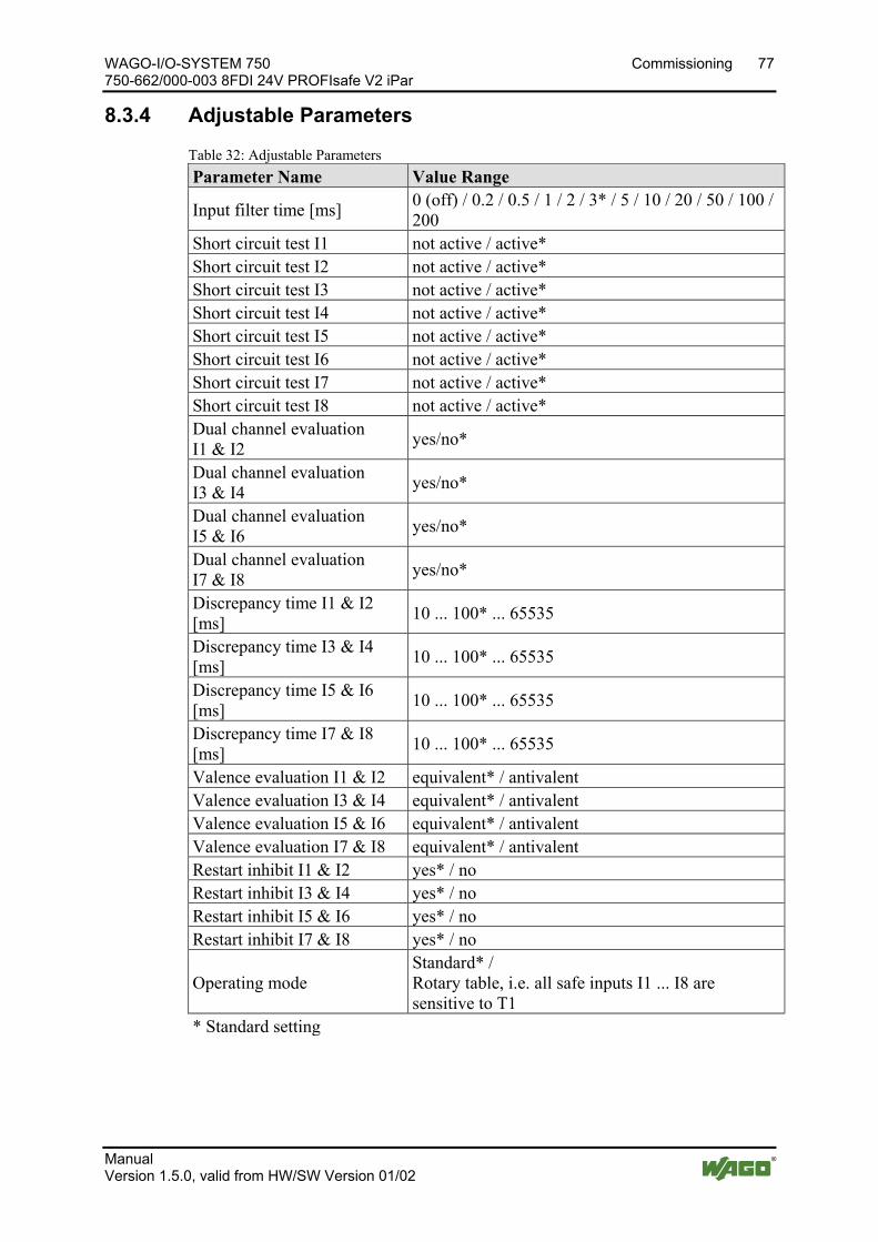
WAGO-I/O-SYSTEM 750 Commissioning 77 750-662/000-003 8FDI 24V PROFIsafe V2 iPar
Manual Version 1.5.0, valid from HW/SW Version 01/02
8.3.4 Adjustable Parameters
Table 32: Adjustable Parameters Parameter Name Value Range
Input filter time [ms] 0 (off) / 0.2 / 0.5 / 1 / 2 / 3* / 5 / 10 / 20 / 50 / 100 / 200
Short circuit test I1 not active / active* Short circuit test I2 not active / active* Short circuit test I3 not active / active* Short circuit test I4 not active / active* Short circuit test I5 not active / active* Short circuit test I6 not active / active* Short circuit test I7 not active / active* Short circuit test I8 not active / active* Dual channel evaluation I1 & I2 yes/no*
Dual channel evaluation I3 & I4 yes/no*
Dual channel evaluation I5 & I6 yes/no*
Dual channel evaluation I7 & I8 yes/no*
Discrepancy time I1 & I2 [ms] 10 ... 100* ... 65535
Discrepancy time I3 & I4 [ms] 10 ... 100* ... 65535
Discrepancy time I5 & I6 [ms] 10 ... 100* ... 65535
Discrepancy time I7 & I8 [ms] 10 ... 100* ... 65535
Valence evaluation I1 & I2 equivalent* / antivalent Valence evaluation I3 & I4 equivalent* / antivalent Valence evaluation I5 & I6 equivalent* / antivalent Valence evaluation I7 & I8 equivalent* / antivalent Restart inhibit I1 & I2 yes* / no Restart inhibit I3 & I4 yes* / no Restart inhibit I5 & I6 yes* / no Restart inhibit I7 & I8 yes* / no
Operating mode Standard* / Rotary table, i.e. all safe inputs I1 ... I8 are sensitive to T1
* Standard setting
Pos: 47.4 /Dokumentation allgemein/Gliederungselemente/---Seitenwechsel--- @ 3\mod_1221108045078_0.docx @ 21810 @ @ 1

78 Commissioning WAGO-I/O-SYSTEM 750 750-662/000-003 8FDI 24V PROFIsafe V2 iPar
Manual Version 1.5.0, valid from HW/SW Version 01/02
Pos: 47.5 /Serie 750 (WAGO-I/O-SYSTEM)/In Betrieb nehmen/Parametrieren mit WAGO-I/O-CHECK/Parametrieren 750-66x/Parameter Eingangsfilterzeit 750-066x/000-003 @ 6\mod_1260795159776_21.docx @ 47096 @ 4 @ 1
8.3.4.1 Parameter Input Filter Time
Configuring the input filter time changes the safe response time! If you change the Input Filter Time parameter, then the safe response time is also changed. See "Response Time" section.
The Input Filter Time parameter is used to set the filter time for all digital inputs of the PROFIsafe I/O module. Setting the filter time to "0 ms" disables the input filter.
Note that the minimum signal duration on a digital input depends on the filter time set. With the input filter, signal changes to a digital input are detected by the PROFIsafe I/O module delayed by the duration of the filter time.
If the signal voltage on the digital input switches from "1" to "0" (signal change 1-0) for a safety requirement (e.g., emergency off requirement), for example, signal voltage "0" must be present for this input pulse duration. If the signal voltage is present shorter than the input pulse duration on the digital input, the signal change is may not be detected by the PROFIsafe I/O module. The following table indicates input pulse durations depending on the input filter time set:
Table 33: Input Pulse Durations Depending on the Input Filter Time Input filter time [ms] 0 0.5 1 2 3 5 10 20 50 100 200
Input pulse duration [ms] 19 20 21 24 28 36 56 96 216 418 816
Use shielded cables for input filter times under 3 ms! If you have set input filter times less than 3 ms, you have to use shielded cables if there is risk of interference (e.g., overvoltage) on the signal lines to prevent possible passivation of the PROFIsafe I/O module.
Pos: 47.6 /Dokumentation allgemein/Gliederungselemente/---Seitenwechsel--- @ 3\mod_1221108045078_0.docx @ 21810 @ @ 1
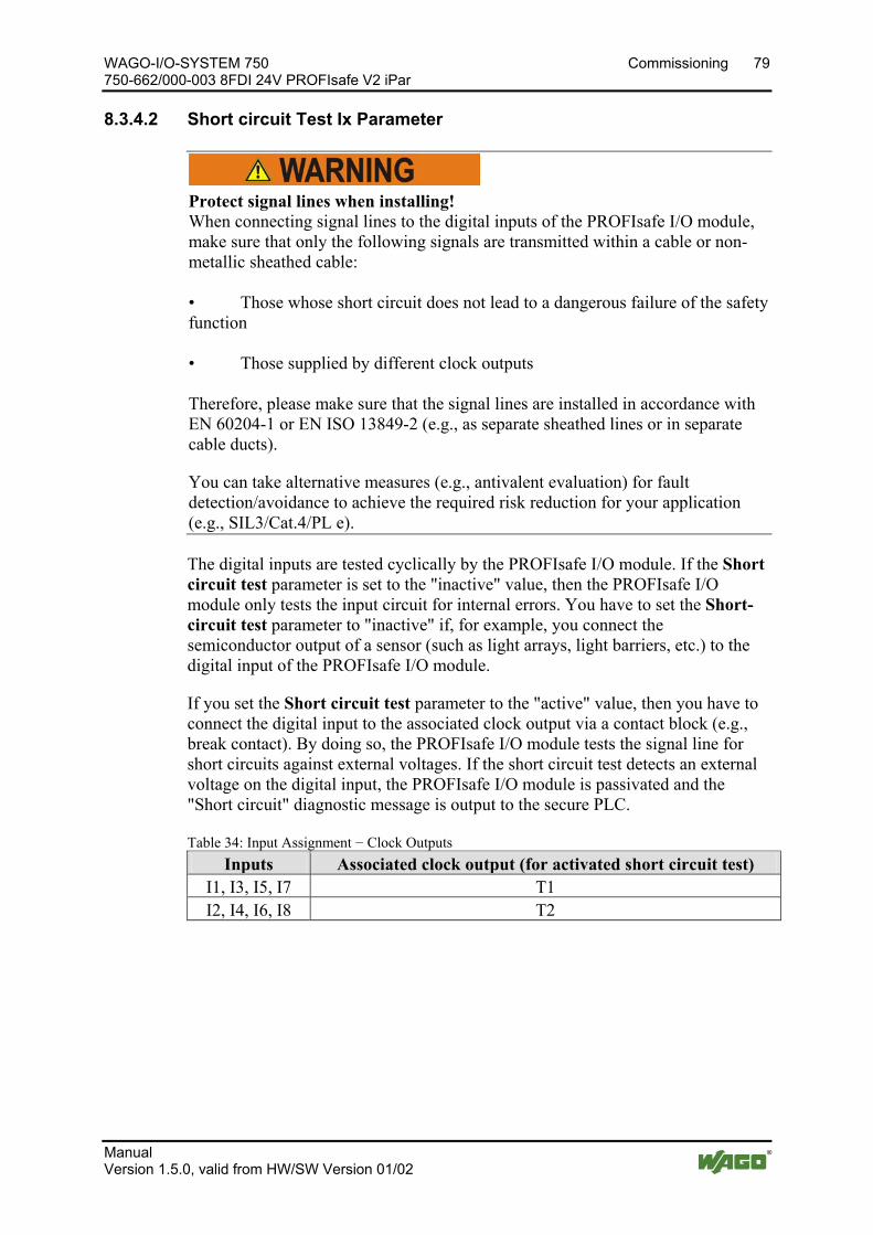
WAGO-I/O-SYSTEM 750 Commissioning 79 750-662/000-003 8FDI 24V PROFIsafe V2 iPar
Manual Version 1.5.0, valid from HW/SW Version 01/02
Pos: 47.7 /Serie 750 (WAGO-I/O-SYSTEM)/In Betrieb nehmen/Parametrieren mit WAGO-I/O-CHECK/Parametrieren 750-66x/Parameter Kurzschlusstest 750-066x/000-003 (8 DI) @ 6\mod_1260795801568_21.docx @ 47099 @ 4 @ 1
8.3.4.2 Short circuit Test Ix Parameter
Protect signal lines when installing! When connecting signal lines to the digital inputs of the PROFIsafe I/O module, make sure that only the following signals are transmitted within a cable or non-metallic sheathed cable: • Those whose short circuit does not lead to a dangerous failure of the safety function • Those supplied by different clock outputs Therefore, please make sure that the signal lines are installed in accordance with EN 60204-1 or EN ISO 13849-2 (e.g., as separate sheathed lines or in separate cable ducts).
You can take alternative measures (e.g., antivalent evaluation) for fault detection/avoidance to achieve the required risk reduction for your application (e.g., SIL3/Cat.4/PL e).
The digital inputs are tested cyclically by the PROFIsafe I/O module. If the Short circuit test parameter is set to the "inactive" value, then the PROFIsafe I/O module only tests the input circuit for internal errors. You have to set the Short-circuit test parameter to "inactive" if, for example, you connect the semiconductor output of a sensor (such as light arrays, light barriers, etc.) to the digital input of the PROFIsafe I/O module.
If you set the Short circuit test parameter to the "active" value, then you have to connect the digital input to the associated clock output via a contact block (e.g., break contact). By doing so, the PROFIsafe I/O module tests the signal line for short circuits against external voltages. If the short circuit test detects an external voltage on the digital input, the PROFIsafe I/O module is passivated and the "Short circuit" diagnostic message is output to the secure PLC.
Table 34: Input Assignment − Clock Outputs Inputs Associated clock output (for activated short circuit test)
I1, I3, I5, I7 T1 I2, I4, I6, I8 T2
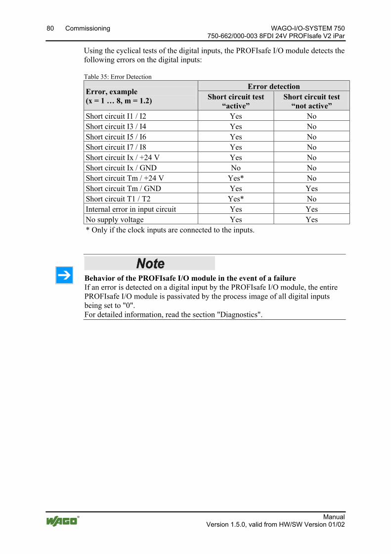
80 Commissioning WAGO-I/O-SYSTEM 750 750-662/000-003 8FDI 24V PROFIsafe V2 iPar
Manual Version 1.5.0, valid from HW/SW Version 01/02
Using the cyclical tests of the digital inputs, the PROFIsafe I/O module detects the following errors on the digital inputs:
Table 35: Error Detection
Error, example (x = 1 … 8, m = 1.2)
Error detection Short circuit test
“active” Short circuit test
“not active” Short circuit I1 / I2 Yes No Short circuit I3 / I4 Yes No Short circuit I5 / I6 Yes No Short circuit I7 / I8 Yes No Short circuit Ix / +24 V Yes No Short circuit Ix / GND No No Short circuit Tm / +24 V Yes* No Short circuit Tm / GND Yes Yes Short circuit T1 / T2 Yes* No Internal error in input circuit Yes Yes No supply voltage Yes Yes * Only if the clock inputs are connected to the inputs.
Pos: 47.8 /Serie 750 (WAGO-I/O-SYSTEM)/In Betrieb nehmen/Parametrieren mit WAGO-I/O-CHECK/Parametrieren 750-66x/Hinweis: Parameter Kurzschlusstest Ix, Verhalten im Fehlerfall ohne Leistungsausgänge @ 7\mod_1272292760831_21.docx @ 55730 @ @ 1
Behavior of the PROFIsafe I/O module in the event of a failure If an error is detected on a digital input by the PROFIsafe I/O module, the entire PROFIsafe I/O module is passivated by the process image of all digital inputs being set to "0". For detailed information, read the section "Diagnostics".
Pos: 47.9 /Dokumentation allgemein/Gliederungselemente/---Seitenwechsel--- @ 3\mod_1221108045078_0.docx @ 21810 @ @ 1

WAGO-I/O-SYSTEM 750 Commissioning 81 750-662/000-003 8FDI 24V PROFIsafe V2 iPar
Manual Version 1.5.0, valid from HW/SW Version 01/02
Pos: 47.10 /Serie 750 (WAGO-I/O-SYSTEM)/In Betrieb nehmen/Parametrieren mit WAGO-I/O-CHECK/Parametrieren 750-66x/Parameter Zweikanalige Auswertung 750-66x/000-003 (8 DI) @ 6\mod_1260796889471_21.docx @ 47102 @ 4 @ 1
8.3.4.3 Parameter Dual Channel Evaluation Ix & Ix+1
The Dual channel evaluation parameter is used to switch the dual channel evaluation of the digital inputs on or off. The value of the parameter can be set to "yes" or "no". If you have set the value of the Operating mode parameter to "Rotary table", then you have to set the Dual channel evaluation parameter to "no".
Depending on the value of the Dual channel evaluation parameter, the signal states of the Ix and Ix+1 inputs are analyzed differently (normal, two-channel), reproduced in the process image and transferred to the secure PLC.
If you have set the Dual channel evaluation parameter to "no", then the signal states of the digital inputs are transmitted independently, i.e., single-channel without analysis to the secure PLC (see Process Image section).
If you have set the Dual channel evaluation parameter to "yes", then the PROFIsafe I/O module combines the respective digital inputs Ix and Ix+ into one input pair. The signal states of the digital inputs are analyzed based on the rule set using the Valence evaluation parameter and applied to the process image as 0 signal or 1 signal (see Valance Evaluation Parameter section).
The PROFIsafe I/O module 750-662/000-003 can be used to create four input pairs from the eight digital inputs.
• Input pair 1: digital input I1 & I2 • Input pair 2: digital input I3 & I4 • Input pair 3: digital input I5 & I6 • Input pair 4: digital input I7 & I8
You can set the value of the Dual channel evaluation parameter for each input pair separately.
If the Dual channel evaluation is set to "yes", then the Short circuit test parameter must be the same! If you have set the Dual channel evaluation parameter to "yes" for two digital inputs, then you have to set the value of the Short circuit test parameter to the same for both digital inputs concerned. The PROFIsafe I/O module checks your setting after transferring to the I/O module and makes automatic corrections if necessary by setting the value to "active" for both digital inputs. The automatic correction is displayed in the WAGO parameterization tool. You can set the values of both digital inputs to the same value after the automatic correction is made.
Pos: 47.11 /Dokumentation allgemein/Gliederungselemente/---Seitenwechsel--- @ 3\mod_1221108045078_0.docx @ 21810 @ @ 1

82 Commissioning WAGO-I/O-SYSTEM 750 750-662/000-003 8FDI 24V PROFIsafe V2 iPar
Manual Version 1.5.0, valid from HW/SW Version 01/02
Pos: 47.12 /Serie 750 (WAGO-I/O-SYSTEM)/In Betrieb nehmen/Parametrieren mit WAGO-I/O-CHECK/Parametrieren 750-66x/Parameter Diskrepanzzeit 750-66x/000-003 @ 6\mod_1260797466718_21.docx @ 47105 @ 4 @ 1
8.3.4.4 Parameter Discrepancy Time Ix & Ix+1
Do not use discrepancy time monitoring as part of the safety function! You may only use discrepancy monitoring for safety applications where monitoring of both contacts does not represent its own safety function, such as emergency Off and, in contrast to this, two-hand control!
The discrepancy time parameter is used for two-channel analysis of two digital inputs Ix & Ix+1. The discrepancy time is then only used by the PROFIsafe I/O module when the operating mode is set to "Standard" and the value of the two-channel analysis parameter is set to "yes".
If you have set the two-channel analysis parameter to "yes", the signal states of the affected input pair are evaluated based on an variable valence rule. The valence rule (antivalence, equivalence) depends on the value of the valence analysis parameter (see Section "Valence Analysis Ix & Ix+1 Parameter").
The PROFIsafe I/O module checks whether the deviation from the valence rule has disappeared after the configured discrepancy time has elapsed. In not, there is a discrepancy error. The PROFIsafe I/O module is passivated and the "Discrepancy time exceeded" diagnostic message is output to the safe PLC.
Use the value of the parameter to specify the maximum permissible time for a deviation (invalid signal state) of both input signal states of the valence rule.
The PROFIsafe I/O module begins discrepancy monitoring as soon as a deviation of the input signal states from the valence rule is detected.
Discrepancy time monitoring is terminated when a valid signal status is achieved (0-signal or 1-signal, see Section "Valence Analysis Ix & Ix+1 Parameter"), depending on the signal status that was present at the digital inputs prior to the beginning of discrepancy monitoring.
You can set the discrepancy time in a value range from 10 ms to 65535 ms for each input pair separately.
Discrepancy Time Monitoring and Discrepancy Time
If you use a two-channel or two single-channel sensors that capture the same physical process variable, changing of the input signals of the connected digital inputs, for example due to mechanical properties or dimensional tolerances, will be delayed.
Discrepancy time monitoring of the two-channel analysis is used to determine sensor errors based on the chronological progression of the signal states. Discrepancy time monitoring is activated if the signal states deviate from the valence rule when
• No equivalent (same) states are detected with an equivalent valence rule
WAGO-I/O-SYSTEM 750 Commissioning 83 750-662/000-003 8FDI 24V PROFIsafe V2 iPar
Manual Version 1.5.0, valid from HW/SW Version 01/02
• No antivalent (opposing) states are detected with an antivalent valence rule
Activate discrepancy time monitoring only after the set input filter time has elapsed! Discrepancy time monitoring is only activated if the input filter time has expired.
During error-free operation, the input signals will assume acceptable signal states within the discrepancy time period. Discrepancy time monitoring is started and also ends before the discrepancy time expires.
Set the value of the discrepancy time parameter such that both digital inputs can complete the change of signal voltage before the discrepancy time has elapsed.
Behavior of the PROFIsafe I/O module during discrepancy time monitoring
If the process image of the PROFIsafe I/O module transfers a 1-signal and a deviation of the input signal states from the valence rule is then detected, discrepancy time monitoring is started. Discrepancy time monitoring is not terminated until a 0-signal is detected.
If the process image of the PROFIsafe I/O module transfers a 0-signal due to the input signal states and a deviation of the input signal states from the valence rule is then detected, discrepancy time monitoring is started. Discrepancy time monitoring is not terminated until either a 0-signal or a 1-signal is detected.
As discrepancy time monitoring progresses in the PROFIsafe I/O module, the "0" value is output from the affected input pair to the safe PLC as a safe process image.
Behavior of the PROFIsafe I/O module after expiration of the discrepancy time
If the invalid input signal status is detected by the PROFIsafe I/O module longer than the configured discrepancy time, there is a discrepancy error, the PROFIsafe I/O module is passivated and the "Discrepancy time exceeded" diagnostic message is output to the safe PLC. The discrepancy error can be caused, for example, by a wire break on a signal line, a sensor error, etc.
Pos: 47.13 /Serie 750 (WAGO-I/O-SYSTEM)/In Betrieb nehmen/Parametrieren mit WAGO-I/O-CHECK/Parametrieren 750-66x/Hinweis: Verhalten der PROFIsafe-Busklemme bei Diskrepanzzeitfehlern ohne Leistungsausgänge @ 7\mod_1272291068909_21.docx @ 55692 @ @ 1
Behavior of the PROFIsafe I/O module during discrepancy time errors If a discrepancy error is detected by the PROFIsafe I/O module, the module then passivates all of the digital inputs. Depending on the setting of the Restart barrier parameter, you can acknowledge the reported error(s) with or without eliminating the cause for the error (see Section "Restart Barrier Ix & Ix+1" Parameter).
84 Commissioning WAGO-I/O-SYSTEM 750 750-662/000-003 8FDI 24V PROFIsafe V2 iPar
Manual Version 1.5.0, valid from HW/SW Version 01/02
Behavior of the PROFIsafe I/O module during discrepancy time errors at several input pairs If a discrepancy error is detected by the PROFIsafe I/O module at several input pairs, the module passivates all of the digital inputs. Depending on the setting of the Restart barrier parameter, you can acknowledge the reported error(s) and any diagnosis without or after eliminating the cause of the error for all affected input pairs (see Section "Restart Barrier Ix & Ix+1" Parameter).
Pos: 47.14 /Dokumentation allgemein/Gliederungselemente/---Seitenwechsel--- @ 3\mod_1221108045078_0.docx @ 21810 @ @ 1

WAGO-I/O-SYSTEM 750 Commissioning 85 750-662/000-003 8FDI 24V PROFIsafe V2 iPar
Manual Version 1.5.0, valid from HW/SW Version 01/02
Pos: 47.15 /Serie 750 (WAGO-I/O-SYSTEM)/In Betrieb nehmen/Parametrieren mit WAGO-I/O-CHECK/Parametrieren 750-66x/Parameter Valenzauswertung 750-66x/000-003 (8 DI) @ 6\mod_1260798151337_21.docx @ 47108 @ 4 @ 1
8.3.4.5 Parameter Valance Evaluation Ix & Ix+1
The Valence evaluation parameter is used for the dual channel evaluation of two digital inputs Ix & Ix+1. The valance evaluation is then only used by the PROFIsafe I/O module if you have set the value of the Operating mode parameter to "Standard" and the value of the Dual channel evaluation parameter to "yes".
The Valence evaluation parameter is used to set the valence rule of the dual channel evaluation to be used for an input pair. You can set the parameter to "Antivalent" or "Equivalent". The valence evaluation can be set separately for each input pair.
Changing input signals caused by interference Changing input signals caused by interference can cause the PFOFIsafe I/O module to transmit the value "0" to the secure PLC in the process image for the input pair affected, a discrepancy error to be detected after the discrepancy time has elapsed and the "Discrepancy time exceeded" diagnostic message to be output. Possible causes may be: • Cross circuit, short circuit and broken cable (user error, wiring error) • Sticky normally open contacts of a reliable sensor • Inadequate filtering of the test signals of a reliable sensor
If you have set the Valence evaluation parameter to "Antivalent", then the PROFIsafe I/O module behaves as follows:
The PROFIsafe I/O module compares the signal states of the digital inputs affected to the opposing values. The following table shows the possible signal states for the antivalent evaluation:
Table 36: Antivalent Evaluation Inputs Process Image
I2 I4 I6 I8
I1 I3 I5 I7
Bit 1 Bit 3 Bit 5 Bit 7
Bit 0 Bit 2 Bit 4 Bit 6
Signal State
0 0 0 0 Illegal 0 1 0 1 1 Signal 1 0 0 0 0 Signal 1 1 0 0 Illegal
After the set discrepancy time has elapsed, an illegal signal state leads to the detection of a discrepancy error by which the PROFIsafe I/O module is deactivated and the "Discrepancy time exceeded" diagnostic message is output.
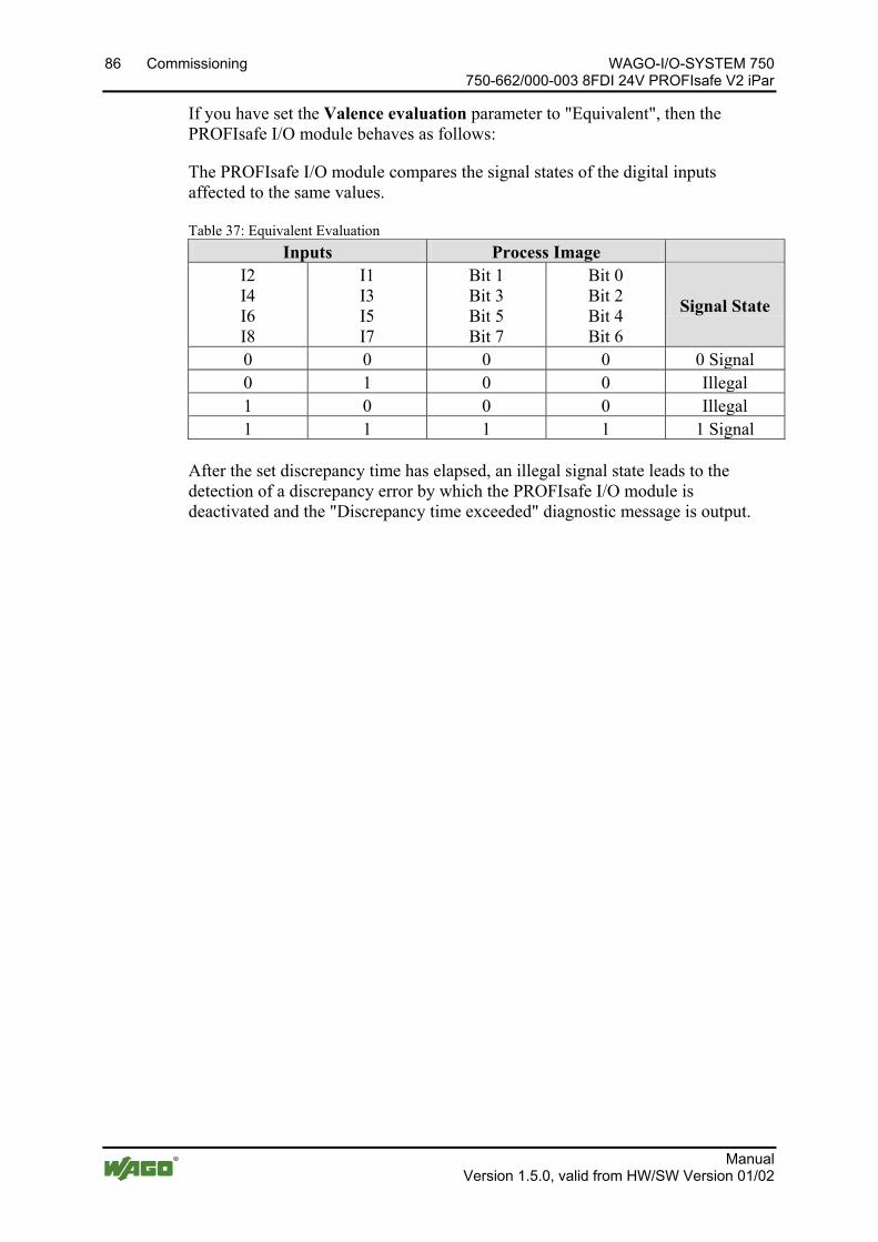
86 Commissioning WAGO-I/O-SYSTEM 750 750-662/000-003 8FDI 24V PROFIsafe V2 iPar
Manual Version 1.5.0, valid from HW/SW Version 01/02
If you have set the Valence evaluation parameter to "Equivalent", then the PROFIsafe I/O module behaves as follows:
The PROFIsafe I/O module compares the signal states of the digital inputs affected to the same values.
Table 37: Equivalent Evaluation Inputs Process Image
I2 I4 I6 I8
I1 I3 I5 I7
Bit 1 Bit 3 Bit 5 Bit 7
Bit 0 Bit 2 Bit 4 Bit 6
Signal State
0 0 0 0 0 Signal 0 1 0 0 Illegal 1 0 0 0 Illegal 1 1 1 1 1 Signal
After the set discrepancy time has elapsed, an illegal signal state leads to the detection of a discrepancy error by which the PROFIsafe I/O module is deactivated and the "Discrepancy time exceeded" diagnostic message is output.
Pos: 47.16 /Dokumentation allgemein/Gliederungselemente/---Seitenwechsel--- @ 3\mod_1221108045078_0.docx @ 21810 @ @ 1
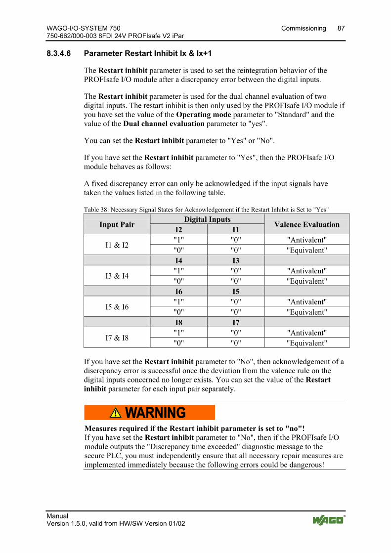
WAGO-I/O-SYSTEM 750 Commissioning 87 750-662/000-003 8FDI 24V PROFIsafe V2 iPar
Manual Version 1.5.0, valid from HW/SW Version 01/02
Pos: 47.17 /Serie 750 (WAGO-I/O-SYSTEM)/In Betrieb nehmen/Parametrieren mit WAGO-I/O-CHECK/Parametrieren 750-66x/Parameter Wiederanlaufsperre 750-066x/000-003 (8 DI) @ 6\mod_1260799203491_21.docx @ 47111 @ 4 @ 1
8.3.4.6 Parameter Restart Inhibit Ix & Ix+1
The Restart inhibit parameter is used to set the reintegration behavior of the PROFIsafe I/O module after a discrepancy error between the digital inputs.
The Restart inhibit parameter is used for the dual channel evaluation of two digital inputs. The restart inhibit is then only used by the PROFIsafe I/O module if you have set the value of the Operating mode parameter to "Standard" and the value of the Dual channel evaluation parameter to "yes".
You can set the Restart inhibit parameter to "Yes" or "No".
If you have set the Restart inhibit parameter to "Yes", then the PROFIsafe I/O module behaves as follows:
A fixed discrepancy error can only be acknowledged if the input signals have taken the values listed in the following table.
Table 38: Necessary Signal States for Acknowledgement if the Restart Inhibit is Set to "Yes"
Input Pair Digital Inputs Valence Evaluation I2 I1
I1 & I2 "1" "0" "Antivalent" "0" "0" "Equivalent"
I4 I3
I3 & I4 "1" "0" "Antivalent" "0" "0" "Equivalent"
I6 I5
I5 & I6 "1" "0" "Antivalent" "0" "0" "Equivalent"
I8 I7
I7 & I8 "1" "0" "Antivalent" "0" "0" "Equivalent"
If you have set the Restart inhibit parameter to "No", then acknowledgement of a discrepancy error is successful once the deviation from the valence rule on the digital inputs concerned no longer exists. You can set the value of the Restart inhibit parameter for each input pair separately.
Measures required if the Restart inhibit parameter is set to "no"! If you have set the Restart inhibit parameter to "No", then if the PROFIsafe I/O module outputs the "Discrepancy time exceeded" diagnostic message to the secure PLC, you must independently ensure that all necessary repair measures are implemented immediately because the following errors could be dangerous!
Pos: 47.18 /Dokumentation allgemein/Gliederungselemente/---Seitenwechsel--- @ 3\mod_1221108045078_0.docx @ 21810 @ @ 1
88 Commissioning WAGO-I/O-SYSTEM 750 750-662/000-003 8FDI 24V PROFIsafe V2 iPar
Manual Version 1.5.0, valid from HW/SW Version 01/02
Pos: 47.19 /Serie 750 (WAGO-I/O-SYSTEM)/In Betrieb nehmen/Parametrieren mit WAGO-I/O-CHECK/Parametrieren 750-66x/Parameter Betriebsart 750-66x/000-003 @ 6\mod_1260799699850_21.docx @ 47114 @ 4 @ 1
8.3.4.7 Parameter Operating Mode
Evaluation of the input signal state in the "Rotary table" operating mode! If you have set the Operating mode to the "Rotary table" value, the temporal logic evaluation of the signal state must be performed by a suitable function block in the safe PLC. Under certain circumstances, you can use the process image of the digital inputs without the suitable function blocks. An overview for using PROFIsafe I/O modules in combination with a safe PLC is summarized in an application note. This application note is available on the Internet at www.wago.com in the area "Service > Documentation > Application Notes...".
You can use the Operating mode parameter to choose between safe standard analysis of the digital inputs (single-channel, two-channel) and the specific "Rotary table" operating mode.
If you want to use the digital inputs single-channel or two-channel, you must set the Operating mode parameter to the "Standard" value.
The choice of operating mode only affects the digital inputs and clock outputs of the PROFIsafe I/O module.
If you want to connect the cam switch of a rotary table or one or more operating mode selector switches to the digital inputs of the PROFIsafe I/O module, you have to set the parameter to the "Rotary table" value.
If you set the Operating mode parameter to "Round table", the PROFIsafe I/O module behaves as follows:
• The Dual channel parameter is only accepted by the PROFIsafe I/O module with the "no" value.
• The Short circuit test parameter is only accepted by the PROFIsafe I/O module with the "active" value.
• All inputs are sensitive to clock output T1 and are tested for short circuit on any 24 V signal source.
• Clock output T2 is switched off.
• The signal states on the digital inputs are not analyzed by the PROFIsafe I/O module.
Pos: 48 /Dokumentation allgemein/Gliederungselemente/---Seitenwechsel--- @ 3\mod_1221108045078_0.docx @ 21810 @ @ 1
WAGO-I/O-SYSTEM 750 Commissioning 89 750-662/000-003 8FDI 24V PROFIsafe V2 iPar
Manual Version 1.5.0, valid from HW/SW Version 01/02
Pos: 49 /Serie 750 (WAGO-I/O-SYSTEM)/In Betrieb nehmen/PROFIsafe in Betrieb nehmen/PROFIsafe Programmierung sichere SPS 75x-066x/000-003 @ 6\mod_1265096470091_21.docx @ 49178 @ 2333 @ 1
8.4 Programming the Safe PLC To configure the safe PLC using the PROFIsafe I/O module 750-662/000-003, the following requirements must be met:
• Use of a suitable safe PLC (e.g., iPar server support)
• Use of a suitable programming and configuration environment
• Selection of a WAGO fieldbus coupler (PROFIBUS, PROFINET)
• Use of the current WAGO device description file (GSD, GSDML)
After selecting a suitable safe PLC, add the required bus system (PROFIBUS or PROFINET) to the hardware configuration environment and configure it accordingly (fieldbus parameters, addresses, names, etc.).
Then select the PROFIBUS or PROFINET fieldbus coupler from the device catalog and connect it to the respective bus system.
The PROFIsafe I/O module can be operated with or without iPar server functionality.
Observe the manufacturer documentation off the safe PLC! The exact programming procedure is available in the manufacturer documentation of the safe PLC.
Use the application notes from WAGO! An overview for using PROFIsafe I/O modules in combination with a safe PLC is summarized in an application note. This application note is available on the Internet at www.wago.com in the area "Service > Documentation > Application Notes..."
Observe dependencies! When creating safety programs, take into account the dependencies between PLC cycle time, call interval of the safety program, expected response times of the safety program and adjustable monitoring times. Details are available in the respective manufacturer documentation.
90 Commissioning WAGO-I/O-SYSTEM 750 750-662/000-003 8FDI 24V PROFIsafe V2 iPar
Manual Version 1.5.0, valid from HW/SW Version 01/02
8.4.1 PROFIsafe I/O Module without iPar Functionality
To use the PROFIsafe I/O module without iPar server functional, select the PROFIsafe I/O module “<v>T - 101 GSD ohne iPAR</v>” from the device catalog and add it to the fieldbus node. Then set the F parameters of the PROFIsafe I/O module in the hardware configuration environment. Then recompile the configuration and transfer it so the safe PLC.
Then configure the PROFIsafe I/O module using the WAGO parameterization tool as described in the section Commissioning” > … > “Parameterization of the PROFIsafe I/O Module with the WAGO Parameterization Tool".
After you have configured the PROFIsafe I/O module, create the required call structure for the safety program. The required system calls and system settings to activate the safety program are added to the project.
Based on your requirements, then create the safety program that contains the basic functions for PROFIsafe subscribers (e.g., reintegration).
After compiling the safety program, you have to check the assignment of PROFIsafe subscribers to the respective run-time group. Then transfer the entire project to the safe PLC.
You have to observe the listed required workflows within the respective manufacture documentation, as well as check and document all safety functions.
8.4.2 PROFIsafe I/O Module with iPar Functionality and iPar Server
To use the PROFIsafe I/O module with iPar server functional, select the I/O module with the “<v>T - 102 GSD mit iPAR</v>” designation from the device catalog and add it to the fieldbus node. You must first set the F_iPar_CRC in the F parameters to 0 in the hardware configuration environment, so that the PROFIsafe I/O module switches to test mode. Then recompile the configuration and transfer it so the safe PLC.
After you have configured the PROFIsafe I/O module, create the required call structure for the safety program. The required system calls and system settings to activate the safety program are added to the project. It is important that the data block for storing the individual parameter (iPar server) is added for each iPar server-capable I/O module.
After compiling the safety program, you have to check the assignment of PROFIsafe subscribers to the respective run-time group. Then transfer the entire project to the safe PLC.
After the safe PLC starts, the PROFIsafe I/O module switches to test mode. In this mode, the safety-related functions of the PROFIsafe I/O module are passivated. Then configure the PROFIsafe I/O module using the WAGO parameterization tool. For more information, read the section “Commissioning” > … > “Parameterization of the PROFIsafe I/O Module with the WAGO
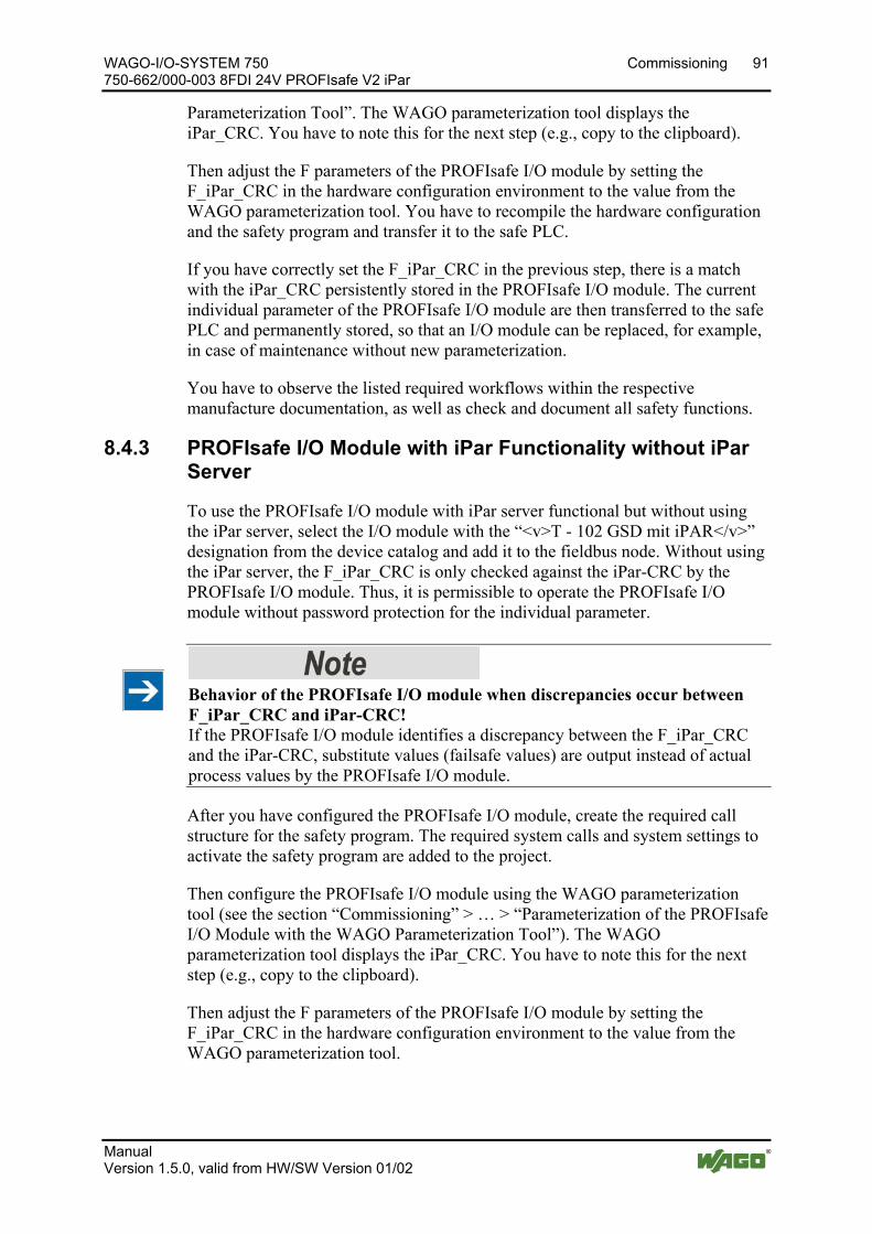
WAGO-I/O-SYSTEM 750 Commissioning 91 750-662/000-003 8FDI 24V PROFIsafe V2 iPar
Manual Version 1.5.0, valid from HW/SW Version 01/02
Parameterization Tool”. The WAGO parameterization tool displays the iPar_CRC. You have to note this for the next step (e.g., copy to the clipboard).
Then adjust the F parameters of the PROFIsafe I/O module by setting the F_iPar_CRC in the hardware configuration environment to the value from the WAGO parameterization tool. You have to recompile the hardware configuration and the safety program and transfer it to the safe PLC.
If you have correctly set the F_iPar_CRC in the previous step, there is a match with the iPar_CRC persistently stored in the PROFIsafe I/O module. The current individual parameter of the PROFIsafe I/O module are then transferred to the safe PLC and permanently stored, so that an I/O module can be replaced, for example, in case of maintenance without new parameterization.
You have to observe the listed required workflows within the respective manufacture documentation, as well as check and document all safety functions.
8.4.3 PROFIsafe I/O Module with iPar Functionality without iPar Server
To use the PROFIsafe I/O module with iPar server functional but without using the iPar server, select the I/O module with the “<v>T - 102 GSD mit iPAR</v>” designation from the device catalog and add it to the fieldbus node. Without using the iPar server, the F_iPar_CRC is only checked against the iPar-CRC by the PROFIsafe I/O module. Thus, it is permissible to operate the PROFIsafe I/O module without password protection for the individual parameter.
Behavior of the PROFIsafe I/O module when discrepancies occur between F_iPar_CRC and iPar-CRC! If the PROFIsafe I/O module identifies a discrepancy between the F_iPar_CRC and the iPar-CRC, substitute values (failsafe values) are output instead of actual process values by the PROFIsafe I/O module.
After you have configured the PROFIsafe I/O module, create the required call structure for the safety program. The required system calls and system settings to activate the safety program are added to the project.
Then configure the PROFIsafe I/O module using the WAGO parameterization tool (see the section “Commissioning” > … > “Parameterization of the PROFIsafe I/O Module with the WAGO Parameterization Tool”). The WAGO parameterization tool displays the iPar_CRC. You have to note this for the next step (e.g., copy to the clipboard).
Then adjust the F parameters of the PROFIsafe I/O module by setting the F_iPar_CRC in the hardware configuration environment to the value from the WAGO parameterization tool.

92 Commissioning WAGO-I/O-SYSTEM 750 750-662/000-003 8FDI 24V PROFIsafe V2 iPar
Manual Version 1.5.0, valid from HW/SW Version 01/02
Using the default iParameter set You can use the default iParameter set of the PROFIsafe I/O module without changing the iParameter settings. Apply the value of the F_iPar_CRC parameter specified in the section “Appendix” > … > “Overview of PROFIsafe F Parameters” by setting the F_iPar_CRC to this value in the hardware configuration environment.
If you have correctly set the F_iPar_CRC, there is a match with the iPar_CRC persistently stored in the PROFIsafe I/O module.
Then compile the hardware configuration and safety program and check the assignment of the PROFIsafe subscribers to the respective run-time group. Then transfer the entire project to the safe PLC.
Note when replacing an I/O module (e.g., in case of maintenance), note that the PROFIsafe I/O module cannot be automatically reparameterized.
Diagnostic message when there is a difference between the F_iPar_CRC and iPar-CRC! When there is a difference between the F_iPar_CRC and iPar-CRC, note that the "Error when downloading the iParam" diagnostic message first appears after about 4.5 minutes. As a remedy, adjust the iParameters of the PROFIsafe I/O module using the WAGO parameterization tool.
You have to observe the listed required workflows within the respective manufacture documentation, as well as check and document all safety functions.
Pos: 50 /Dokumentation allgemein/Gliederungselemente/---Seitenwechsel--- @ 3\mod_1221108045078_0.docx @ 21810 @ @ 1
WAGO-I/O-SYSTEM 750 Diagnostics 93 750-662/000-003 8FDI 24V PROFIsafe V2 iPar
Manual Version 1.5.0, valid from HW/SW Version 01/02
Pos: 51 /Alle Serien (Allgemeine Module)/Überschriften für alle Serien/Diagnose/Diagnose - Überschrift 1 @ 4\mod_1240831069471_21.docx @ 31372 @ 1 @ 1
9 Diagnostics Pos: 52.1 /Serie 750 (WAGO-I/O-SYSTEM)/Diagnose/Busklemmen/PROFIsafe-Diagnose/PROFIsafe-Diagnose 75x-066x/000-003 Einleitung FDI @ 7\mod_1272349455983_21.docx @ 55780 @ 22 @ 1
9.1 Behavior in the Event of an Error The PROFIsafe I/O module detects internal and external errors. Internal errors are detected by continuous self testing. Depending on the configuration, external errors are detected and diagnosed by testing the external circuits to the extent possible. When detecting an external error, a diagnostic message is output to the safe PLC. The diagnostic messages for external errors are described in the section "Diagnosis of Errors".
In the event of an error, all digital inputs of the PROFIsafe I/O module are passivated by outputting the substitute values (failsafe values) instead of actual process values. For the digital inputs, the substitute values "0" for the process image are transferred to the safe PLC.
The external errors can be eliminated by maintenance personnel and must then be acknowledged by the operator triggering an acknowledgement (operator acknowledgement). Possible acknowledgement is indicated by a 0.5 Hz, green flashing "PROFIsafe Status" LED. An error check is always performed on acknowledgement. If the same error, or a different one continues to be present, it is detected at once and the PROFIsafe I/O module is repassivated.
Both internal and external errors can be evoked by strong EMC events. If an internal error is diagnosed, the PROFIsafe I/O module switches off for safety. In this case, acknowledgement by the operator remains ineffective.
To check whether the cause of an internal error was a temporary EMC event and thus caused the safety-oriented shutdown, switching the entire fieldbus node off and then on again can be performed in an attempt to activate the PROFIsafe I/O module again.
If shutdowns occur frequently due to internal errors, the PROFIsafe I/O module should be replaced.
In this case, return the defective PROFIsafe I/O module to WAGO Kontakttechnik GmbH & Co. KG for fault analysis.
94 Diagnostics WAGO-I/O-SYSTEM 750 750-662/000-003 8FDI 24V PROFIsafe V2 iPar
Manual Version 1.5.0, valid from HW/SW Version 01/02
9.2 Diagnosis of Errors
The diagnosis of the PROFIsafe I/O module is not safety related! The diagnosis of the PROFIsafe I/O module cannot be part of the safety function under any circumstances.
After detecting internal or external errors, the PROFIsafe I/O module outputs diagnostic messages to the safe PLC via the fieldbus. Diagnostic messages help you identify errors and implement appropriate measures for error correction.
The PROFIsafe I/O module provides you with diagnostic messages about the display elements and the diagnostic services of the respective fieldbus system (PROFIBUS or PROFINET). The presentation of diagnostic information via the LEDs is available in the section "Display Elements".
All diagnostic messages transferred to and displayed on the safe PLC are listed below in alphabetical order. Information about error correction and resolutions for each diagnostic message can also be displayed on the safe PLC for released channel and module diagnostics. The configuration tool of your safe PLC can be used to set the release of the channel and module diagnostics.
The structure of the diagnostic messages is described in the fieldbus coupler manuals.
Pos: 52.2 /Serie 750 (WAGO-I/O-SYSTEM)/Gerätebeschreibung/Einleitung/Einsatzbereich/Einsatzbereich 75x-066x/000-003 @ 23\mod_1437391184128_21.docx @ 186490 @ @ 1
The PROFIsafe I/O module 750-662/000-003 can be operated on the WAGO-I/O-SYSTEM 750 fieldbus couplers specified in section “Technical Data” > … > “Communication”:
Pos: 52.3 /Serie 750 (WAGO-I/O-SYSTEM)/Diagnose/Busklemmen/PROFIsafe-Diagnose/PROFIsafe-Diagnose 75x-066x/000-003 Fehlermeldungen FDI @ 7\mod_1265787182032_21.docx @ 50184 @ @ 1
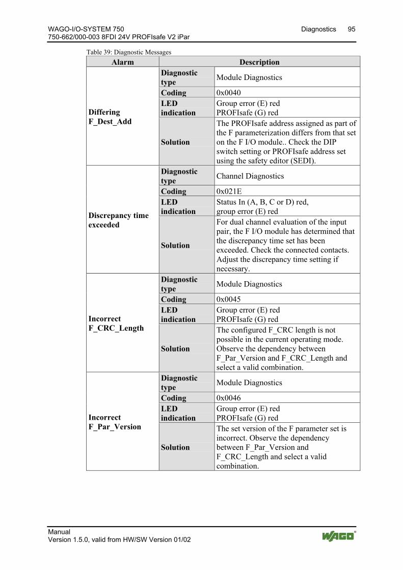
WAGO-I/O-SYSTEM 750 Diagnostics 95 750-662/000-003 8FDI 24V PROFIsafe V2 iPar
Manual Version 1.5.0, valid from HW/SW Version 01/02
Table 39: Diagnostic Messages Alarm Description
Differing F_Dest_Add
Diagnostic type Module Diagnostics
Coding 0x0040 LED indication
Group error (E) red PROFIsafe (G) red
Solution
The PROFIsafe address assigned as part of the F parameterization differs from that set on the F I/O module.. Check the DIP switch setting or PROFIsafe address set using the safety editor (SEDI).
Discrepancy time exceeded
Diagnostic type Channel Diagnostics
Coding 0x021E LED indication
Status In (A, B, C or D) red, group error (E) red
Solution
For dual channel evaluation of the input pair, the F I/O module has determined that the discrepancy time set has been exceeded. Check the connected contacts. Adjust the discrepancy time setting if necessary.
Incorrect F_CRC_Length
Diagnostic type Module Diagnostics
Coding 0x0045 LED indication
Group error (E) red PROFIsafe (G) red
Solution
The configured F_CRC length is not possible in the current operating mode. Observe the dependency between F_Par_Version and F_CRC_Length and select a valid combination.
Incorrect F_Par_Version
Diagnostic type Module Diagnostics
Coding 0x0046 LED indication
Group error (E) red PROFIsafe (G) red
Solution
The set version of the F parameter set is incorrect. Observe the dependency between F_Par_Version and F_CRC_Length and select a valid combination.
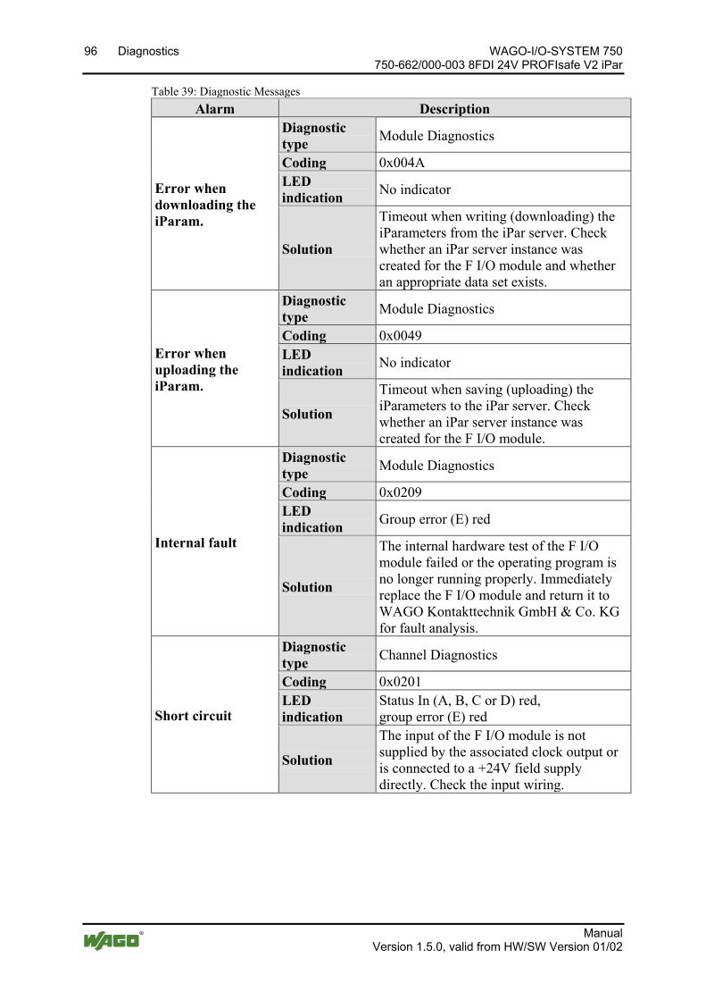
96 Diagnostics WAGO-I/O-SYSTEM 750 750-662/000-003 8FDI 24V PROFIsafe V2 iPar
Manual Version 1.5.0, valid from HW/SW Version 01/02
Table 39: Diagnostic Messages Alarm Description
Error when downloading the iParam.
Diagnostic type Module Diagnostics
Coding 0x004A LED indication No indicator
Solution
Timeout when writing (downloading) the iParameters from the iPar server. Check whether an iPar server instance was created for the F I/O module and whether an appropriate data set exists.
Error when uploading the iParam.
Diagnostic type Module Diagnostics
Coding 0x0049 LED indication No indicator
Solution
Timeout when saving (uploading) the iParameters to the iPar server. Check whether an iPar server instance was created for the F I/O module.
Internal fault
Diagnostic type Module Diagnostics
Coding 0x0209 LED indication Group error (E) red
Solution
The internal hardware test of the F I/O module failed or the operating program is no longer running properly. Immediately replace the F I/O module and return it to WAGO Kontakttechnik GmbH & Co. KG for fault analysis.
Short circuit
Diagnostic type Channel Diagnostics
Coding 0x0201 LED indication
Status In (A, B, C or D) red, group error (E) red
Solution
The input of the F I/O module is not supplied by the associated clock output or is connected to a +24V field supply directly. Check the input wiring.

WAGO-I/O-SYSTEM 750 Diagnostics 97 750-662/000-003 8FDI 24V PROFIsafe V2 iPar
Manual Version 1.5.0, valid from HW/SW Version 01/02
Table 39: Diagnostic Messages Alarm Description
Short circuit on T1
Diagnostic type Module Diagnostics
Coding 0x020B LED indication Group error (E) red
Solution
Clock output T1 of the F I/O module has short circuited with the 0V potential of the field supply. Check the clock output wiring.
Short circuit on T2
Diagnostic type Module Diagnostics
Coding 0x020C LED indication Group error (E) red
Solution
Clock output T2 of the F I/O module has short circuited with the 0V potential of the field supply. Check the clock output wiring.
Non-supported F_Block_ID
Diagnostic type Module Diagnostics
Coding 0x004C LED indication
Group error (E) red PROFIsafe (G) red
Solution
The F parameter block signaled by the F_Block_ID is not supported by the F I/O module. Use an F parameter block supported by the F I/O module.
Non-supported F_SIL
Diagnostic type Module Diagnostics
Coding 0x0044 LED indication
Group error (E) red PROFIsafe (G) red
Solution The F I/O module cannot be operated in the configured SIL. Correct the F parameterization.
Safety-oriented tripping
Diagnostic type Module Diagnostics
Coding 0x0219 LED indication Group error (E) red, 2 Hz flashing
Solution
The F I/O module has taken the safe state and switched off the outputs. Immediately replace the F I/O module and return it to WAGO Kontakttechnik GmbH & Co. KG for fault analysis.
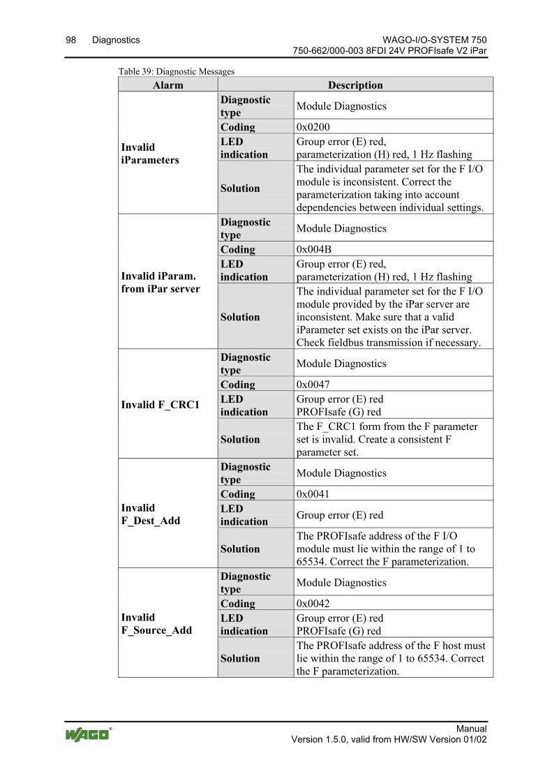
98 Diagnostics WAGO-I/O-SYSTEM 750 750-662/000-003 8FDI 24V PROFIsafe V2 iPar
Manual Version 1.5.0, valid from HW/SW Version 01/02
Table 39: Diagnostic Messages Alarm Description
Invalid iParameters
Diagnostic type Module Diagnostics
Coding 0x0200 LED indication
Group error (E) red, parameterization (H) red, 1 Hz flashing
Solution
The individual parameter set for the F I/O module is inconsistent. Correct the parameterization taking into account dependencies between individual settings.
Invalid iParam. from iPar server
Diagnostic type Module Diagnostics
Coding 0x004B LED indication
Group error (E) red, parameterization (H) red, 1 Hz flashing
Solution
The individual parameter set for the F I/O module provided by the iPar server are inconsistent. Make sure that a valid iParameter set exists on the iPar server. Check fieldbus transmission if necessary.
Invalid F_CRC1
Diagnostic type Module Diagnostics
Coding 0x0047 LED indication
Group error (E) red PROFIsafe (G) red
Solution The F_CRC1 form from the F parameter set is invalid. Create a consistent F parameter set.
Invalid F_Dest_Add
Diagnostic type Module Diagnostics
Coding 0x0041 LED indication Group error (E) red
Solution The PROFIsafe address of the F I/O module must lie within the range of 1 to 65534. Correct the F parameterization.
Invalid F_Source_Add
Diagnostic type Module Diagnostics
Coding 0x0042 LED indication
Group error (E) red PROFIsafe (G) red
Solution The PROFIsafe address of the F host must lie within the range of 1 to 65534. Correct the F parameterization.
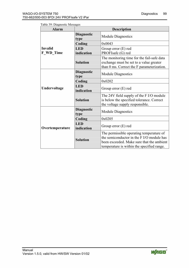
WAGO-I/O-SYSTEM 750 Diagnostics 99 750-662/000-003 8FDI 24V PROFIsafe V2 iPar
Manual Version 1.5.0, valid from HW/SW Version 01/02
Table 39: Diagnostic Messages Alarm Description
Invalid F_WD_Time
Diagnostic type Module Diagnostics
Coding 0x0043 LED indication
Group error (E) red PROFIsafe (G) red
Solution The monitoring time for the fail-safe data exchange must be set to a value greater than 0 ms. Correct the F parameterization.
Undervoltage
Diagnostic type Module Diagnostics
Coding 0x0202 LED indication Group error (E) red
Solution The 24V field supply of the F I/O module is below the specified tolerance. Correct the voltage supply responsible.
Overtemperature
Diagnostic type Module Diagnostics
Coding 0x0205 LED indication Group error (E) red
Solution
The permissible operating temperature of the semiconductor in the F I/O module has been exceeded. Make sure that the ambient temperature is within the specified range.
Pos: 52.4 /Dokumentation allgemein/Gliederungselemente/---Seitenwechsel--- @ 3\mod_1221108045078_0.docx @ 21810 @ @ 1

100 Diagnostics WAGO-I/O-SYSTEM 750 750-662/000-003 8FDI 24V PROFIsafe V2 iPar
Manual Version 1.5.0, valid from HW/SW Version 01/02
Pos: 52.5 /Serie 750 (WAGO-I/O-SYSTEM)/Diagnose/Busklemmen/PROFIsafe-DiagnosePROFIsafe-Diagnose 75x-066x/000-003 Fehlermeldungen quittieren @ 23\mod_1436261451512_21.docx @ 185392 @ 233 @ 1
9.3 Acknowledging Error Messages When detecting an error, a message is sent by the PROFIbus I/O module to the safe PLC. More information about error detection by the PROFIsaf I/O module is available in the section “Diagnosis” > … > “Error Response” and in the section “Diagnosis” > … > “Diagnosis of Errors”.
In the PROFIsafe I/O module, passivation of the process data is automatic in the event of error detection and message. During this process, all digital inputs and outputs of the PROFIsafe I/O module are passivated by outputting the substitute values (fail-safe values) instead of actual process values.
To reset the passivation, acknowledgement is required by the user. A call for depassivation of the process data in the PROFIsafe I/O module is displayed by the F-Host with the “Acknowledgement Request” signal. The actual signal designation for the acknowledgement request depends on the manufacturer of the controller.
Two variants are available to carry out the depassivation:
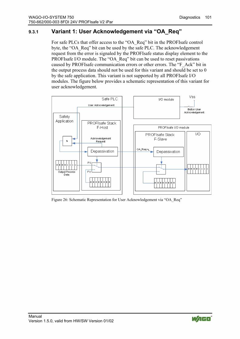
WAGO-I/O-SYSTEM 750 Diagnostics 101 750-662/000-003 8FDI 24V PROFIsafe V2 iPar
Manual Version 1.5.0, valid from HW/SW Version 01/02
9.3.1 Variant 1: User Acknowledgement via “OA_Req”
For safe PLCs that offer access to the “OA_Req” bit in the PROFIsafe control byte, the “OA_Req” bit can be used by the safe PLC. The acknowledgement request from the error is signaled by the PROFIsafe status display element to the PROFIsafe I/O module. The “OA_Req” bit can be used to reset passivations caused by PROFIsafe communication errors or other errors. The “F_Ack” bit in the output process data should not be used for this variant and should be set to 0 by the safe application. This variant is not supported by all PROFIsafe I/O modules. The figure below provides a schematic representation of this variant for user acknowledgement.
Figure 26: Schematic Representation for User Acknowledgement via “OA_Req”
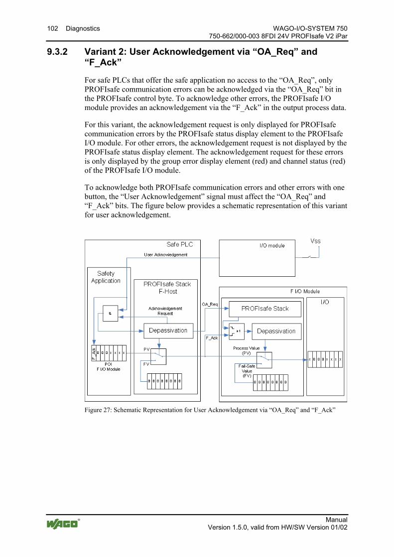
102 Diagnostics WAGO-I/O-SYSTEM 750 750-662/000-003 8FDI 24V PROFIsafe V2 iPar
Manual Version 1.5.0, valid from HW/SW Version 01/02
9.3.2 Variant 2: User Acknowledgement via “OA_Req” and “F_Ack”
For safe PLCs that offer the safe application no access to the “OA_Req”, only PROFIsafe communication errors can be acknowledged via the “OA_Req” bit in the PROFIsafe control byte. To acknowledge other errors, the PROFIsafe I/O module provides an acknowledgement via the “F_Ack” in the output process data.
For this variant, the acknowledgement request is only displayed for PROFIsafe communication errors by the PROFIsafe status display element to the PROFIsafe I/O module. For other errors, the acknowledgement request is not displayed by the PROFIsafe status display element. The acknowledgement request for these errors is only displayed by the group error display element (red) and channel status (red) of the PROFIsafe I/O module.
To acknowledge both PROFIsafe communication errors and other errors with one button, the “User Acknowledgement” signal must affect the “OA_Req” and “F_Ack” bits. The figure below provides a schematic representation of this variant for user acknowledgement.
Figure 27: Schematic Representation for User Acknowledgement via “OA_Req” and “F_Ack”
Pos: 53 /Dokumentation allgemein/Gliederungselemente/---Seitenwechsel--- @ 3\mod_1221108045078_0.docx @ 21810 @ @ 1

WAGO-I/O-SYSTEM 750 Service 103 750-662/000-003 8FDI 24V PROFIsafe V2 iPar
Manual Version 1.5.0, valid from HW/SW Version 01/02
Pos: 54 /Alle Serien (Allgemeine Module)/Überschriften für alle Serien/Service (Wartung)/Service - Überschrift 1 @ 4\mod_1241771948421_21.docx @ 32830 @ 1 @ 1
10 Service Pos: 55 /Serie 750 (WAGO-I/O-SYSTEM)/Service/PROFIsafePROFIsafe-Busklemme austauschen @ 7\mod_1265809189196_21.docx @ 50260 @ 23344344 @ 1
10.1 Replacing a PROFIsafe I/O Module Replacing a PROFIsafe I/O module with a PROFIsafe I/O module of the same type is described in the following.
Replacing a PROFIsafe I/O module with an I/O module of another type is always associated with a new project design (see section “Commissioning” > … > “Programming the Safe PLC”).
10.1.1 Procedure
When replacing a PROFIsafe I/O module, first perform the following steps:
• Switch off the supply voltage of the fieldbus node in which the I/O module to be replaced is found.
• Pull the I/O module to be replaced out of the fieldbus node (see section “Mounting” > … > “Inserting and Removing Devices”).
• Read the PROFIsafe address on the coding switch of the I/O module to be replaced and apply this setting to the replacement I/O module.
• Plug the replacement I/O module into the position of the I/O module to be replaced in the fieldbus node.
• Switch on again the supply voltage of the fieldbus node concerned.
Then perform the one of the following steps based on your system configuration:
• If the setting of the coding switch of the I/O module to be replaced has a value not equal to 0 and it is operated with iPar server functionality, continue reading in section “Service” > … > “PROFIsafe Address Set Using the Coding Switch”.
• If the setting of the coding switch of the I/O module to be replaced has a value equal to 0 and it is operated with iPar server functionality, continue reading in section “Service” > … > “PROFIsafe Address Set Using the Parameterization Tool”.
• If the setting of the coding switch of the I/O module to be replaced has a value not equal to 0 and it is not operated with iPar server functionality, continue reading in section “Service” > … > “PROFIsafe Address Set Using the Parameterization Tool”.
• If the setting of the coding switch of the I/O module to be replaced has a value equal to 0 and it is not operated with iPar server functionality, continue reading in section “Service” > … > “PROFIsafe Address Set Using the Coding Switch".
104 Service WAGO-I/O-SYSTEM 750 750-662/000-003 8FDI 24V PROFIsafe V2 iPar
Manual Version 1.5.0, valid from HW/SW Version 01/02
10.1.2 I/O Module with iPar Server Functionality
10.1.2.1 PROFIsafe Address Set Using the Coding Switch
If the PROFIsafe address of the I/O module to be replaced is set using the coding switch on the side, i.e., the switch setting does not equal 0, proceed with replacing the I/O module as follows:
• Acknowledge the PROFIsafe communication error in the safe PLC.
After acknowledging the error, the replacement I/O module automatically requests its individual parameters from the iPar server. The safety-related verification of these parameters occurs in the PROFIsafe I/O module. If the verification step is unsuccessful, the replacement I/O module sends a second request to the iPar server. If the process cannot be completed successfully, the replacement I/O module remains in its initial state and must be configured using the WAGO parameterization tool (see section “Commissioning” > … > “Parameterization of the PROFIsafe I/O Module with the WAGO Parameterization Tool”).
10.1.2.2 PROFIsafe Address Set Using the Parameterization Tool
If the setting of the coding switch of the I/O module to be replaced represents the value 0, the PROFIsafe address of the I/O module to be replaced must be set using the parameterization tool (see section “Commissioning” > … > “Parameterization of the PROFIsafe I/O Module with the WAGO Parameterization Tool”). After successfully setting the PROFIsafe address, proceed as follows:
• Acknowledge the PROFIsafe communication error in the safe PLC.
After acknowledging the error, the replacement I/O module automatically requests its individual parameters from the iPar server. The safety-related verification of these parameters occurs in the PROFIsafe I/O module. If the verification step is unsuccessful, the replacement I/O module sends a second request to the iPar server. If the process cannot be completed successfully, the replacement I/O module remains in its initial state and must be configured using the WAGO parameterization tool (see section “Commissioning” > … > “Parameterization of the PROFIsafe I/O Module with the WAGO Parameterization Tool”).
10.1.3 I/O Module without iPar Server Functionality
10.1.3.1 PROFIsafe Address Set Using the Coding Switch
If the PROFIsafe address of the I/O module to be replaced is set using the coding switch, i.e., the switch setting does not equal 0, use the WAGO parameterization tool to configure the replacement I/O module (see section “Commissioning” > … > “Parameterization of the PROFIsafe I/O Module with the WAGO Parameterization Tool”).

WAGO-I/O-SYSTEM 750 Service 105 750-662/000-003 8FDI 24V PROFIsafe V2 iPar
Manual Version 1.5.0, valid from HW/SW Version 01/02
10.1.3.2 PROFIsafe Address Set Using the Parameterization Tool
If the setting of the coding switch of the I/O module to be replaced represents the value 0, the PROFIsafe address of the replacement I/O module must be set using the parameterization tool (see section “Commissioning” > … > “Parameterization of the PROFIsafe I/O Module with the WAGO Parameterization Tool”). In addition to setting the PROFIsafe address, also configure the replacement I/O module using the WAGO parameterization tool (see section “Commissioning” > … > “Parameterization of the PROFIsafe I/O Module with the WAGO Parameterization Tool”).
Determine the PROFIsafe address if the coding switch is set to "0"! You can use the WAGO parameterization tool to read the current PROFIsafe address from the PROFIsafe I/O module to be replaced.
Pos: 56 /Dokumentation allgemein/Gliederungselemente/---Seitenwechsel--- @ 3\mod_1221108045078_0.docx @ 21810 @ @ 1
106 Use in Hazardous Environments WAGO-I/O-SYSTEM 750 750-662/000-003 8FDI 24V PROFIsafe V2 iPar
Manual Version 1.5.0, valid from HW/SW Version 01/02
Pos: 57.1 /Alle Serien (Allgemeine Module)/Einsatz in Ex-Bereichen/Einsatz in explosionsgefährdeten Bereichen - Überschrift 1 @ 3\mod_1224075191281_21.docx @ 24084 @ 1 @ 1
11 Use in Hazardous Environments Pos: 57.2 /Serie 750 (WAGO-I/O-SYSTEM)/Einsatz in Ex-Bereichen/Einsatzbereich Serie 750 @ 3\mod_1234272230203_21.docx @ 27500 @ @ 1
The WAGO-I/O-SYSTEM 750 (electrical equipment) is designed for use in Zone 2 hazardous areas.
The following sections include both the general identification of components (devices) and the installation regulations to be observed. The individual subsections of the “Installation Regulations” section must be taken into account if the I/O module has the required approval or is subject to the range of application of the ATEX directive.
Pos: 57.3 /Dokumentation allgemein/Gliederungselemente/---Seitenwechsel--- @ 3\mod_1221108045078_0.docx @ 21810 @ @ 1

WAGO-I/O-SYSTEM 750 Use in Hazardous Environments 107 750-662/000-003 8FDI 24V PROFIsafe V2 iPar
Manual Version 1.5.0, valid from HW/SW Version 01/02
Pos: 57.4 /Serie 750 (WAGO-I/O-SYSTEM)/Einsatz in Ex-Bereichen/Beispielhafter Aufbau der Kennzeichnung - Überschrift 2 @ 3\mod_1224157499140_21.docx @ 24182 @ 2 @ 1
11.1 Marking Configuration Examples Pos: 57.5 /Serie 750 (WAGO-I/O-SYSTEM)/Einsatz in Ex-Bereichen/Kennzeichnung für Europa gemäß ATEX und IEC-EX - Überschrift 3 @ 3\mod_1224157620203_21.docx @ 24185 @ 3 @ 1
11.1.1 Marking for Europe According to ATEX and IEC-Ex Pos: 57.6 /Serie 750 (WAGO-I/O-SYSTEM)/Einsatz in Ex-Bereichen/Beispielbedruckung der ATEX- und IEC-Ex-zugelassenen Busklemmen gemäß CENELEC und IEC_2013 @ 14\mod_1360569228625_21.docx @ 111294 @ @ 1
Figure 28: Side Marking Example for Approved I/O Modules According to ATEX and IECEx
Figure 29: Text Detail – Marking Example for Approved I/O Modules According to ATEX and IECEx.
108 Use in Hazardous Environments WAGO-I/O-SYSTEM 750 750-662/000-003 8FDI 24V PROFIsafe V2 iPar
Manual Version 1.5.0, valid from HW/SW Version 01/02
Table 40: Description of Marking Example for Approved I/O Modules According to ATEX and IECEx Printing on Text Description TÜV 07 ATEX 554086 X IECEx TUN 09.0001 X
Approving authority and certificate numbers
Dust II Equipment group: All except mining 3D Category 3 (Zone 22) Ex Explosion protection mark tc Dc Type of protection and equipment protection
level (EPL):protection by enclosure IIIC Explosion group of dust T 135°C Max. surface temperature of the enclosure
(without a dust layer) Mining I Equipment group: Mining M2 Category: High level of protection Ex Explosion protection mark d Mb Type of protection and equipment protection
level (EPL): Flameproof enclosure I Explosion group for electrical equipment for
mines susceptible to firedamp Gases II Equipment group: All except mining 3G Category 3 (Zone 2) Ex Explosion protection mark nA Gc Type of protection and equipment protection
level (EPL): Non-sparking equipment nC Gc Type of protection and equipment protection
level (EPL): Sparking apparatus with protected contacts. A device which is so constructed that the external atmosphere cannot gain access to the interior
IIC Explosion group of gas and vapours T4 Temperature class: Max. surface temperature
135°C
Pos: 57.7 /Dokumentation allgemein/Gliederungselemente/---Seitenwechsel--- @ 3\mod_1221108045078_0.docx @ 21810 @ @ 1
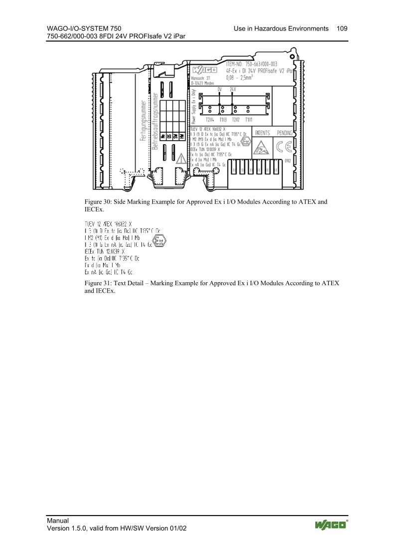
WAGO-I/O-SYSTEM 750 Use in Hazardous Environments 109 750-662/000-003 8FDI 24V PROFIsafe V2 iPar
Manual Version 1.5.0, valid from HW/SW Version 01/02
Pos: 57.8 /Serie 750 (WAGO-I/O-SYSTEM)/Einsatz in Ex-Bereichen/Beispielbedruckung der Ex-i- und IEC-Ex-i-zugelassenen Busklemmen gemäß CENELEC und IEC_2013 @ 14\mod_1360569320118_21.docx @ 111298 @ @ 1
Figure 30: Side Marking Example for Approved Ex i I/O Modules According to ATEX and IECEx.
Figure 31: Text Detail – Marking Example for Approved Ex i I/O Modules According to ATEX and IECEx.

110 Use in Hazardous Environments WAGO-I/O-SYSTEM 750 750-662/000-003 8FDI 24V PROFIsafe V2 iPar
Manual Version 1.5.0, valid from HW/SW Version 01/02
Table 41: Description of Marking Example for Approved Ex i I/O Modules According to ATEX and IECEx Inscription Text Description TÜV 07 ATEX 554086 X IECEx TUN 09.0001X TÜV 12 ATEX 106032 X IECEx TUN 12.0039 X
Approving authority and certificate numbers
Dust II Equipment group: All except mining 3(1)D Category 3 (Zone 22) equipment containing a safety
device for a category 1 (Zone 20) equipment 3(2)D Category 3 (Zone 22) equipment containing a safety
device for a category 2 (Zone 21) equipment Ex Explosion protection mark tc Dc Type of protection and equipment protection level
(EPL): protection by enclosure [ia Da] Type of protection and equipment protection level
(EPL): associated apparatus with intrinsic safety circuits for use in Zone 20
[ib Db] Type of protection and equipment protection level (EPL): associated apparatus with intrinsic safety circuits for use in Zone 21
IIIC Explosion group of dust T 135°C Max. surface temperature of the enclosure (without a
dust layer) Mining I Equipment Group: Mining M2 (M1) Category: High level of protection with electrical
circuits which present a very high level of protection Ex d Mb Explosion protection mark with Type of protection
and equipment protection level (EPL): Flameproof enclosure
[ia Ma] Type of protection and equipment protection level (EPL): associated apparatus with intrinsic safety electrical circuits
I
Explosion group for electrical equipment for mines susceptible to firedamp
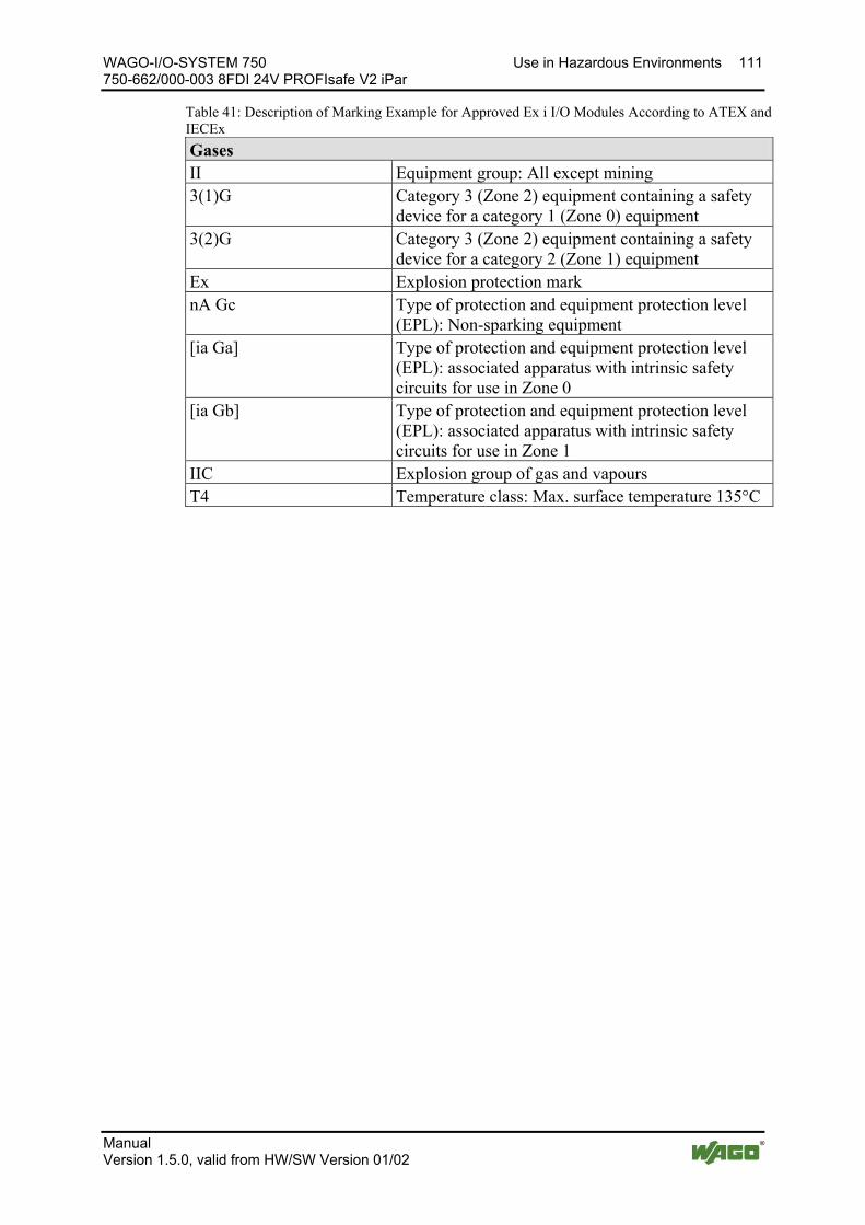
WAGO-I/O-SYSTEM 750 Use in Hazardous Environments 111 750-662/000-003 8FDI 24V PROFIsafe V2 iPar
Manual Version 1.5.0, valid from HW/SW Version 01/02
Table 41: Description of Marking Example for Approved Ex i I/O Modules According to ATEX and IECEx Gases II Equipment group: All except mining 3(1)G Category 3 (Zone 2) equipment containing a safety
device for a category 1 (Zone 0) equipment 3(2)G Category 3 (Zone 2) equipment containing a safety
device for a category 2 (Zone 1) equipment Ex Explosion protection mark nA Gc Type of protection and equipment protection level
(EPL): Non-sparking equipment [ia Ga] Type of protection and equipment protection level
(EPL): associated apparatus with intrinsic safety circuits for use in Zone 0
[ia Gb] Type of protection and equipment protection level (EPL): associated apparatus with intrinsic safety circuits for use in Zone 1
IIC Explosion group of gas and vapours T4 Temperature class: Max. surface temperature 135°C
Pos: 57.9 /Dokumentation allgemein/Gliederungselemente/---Seitenwechsel--- @ 3\mod_1221108045078_0.docx @ 21810 @ @ 1
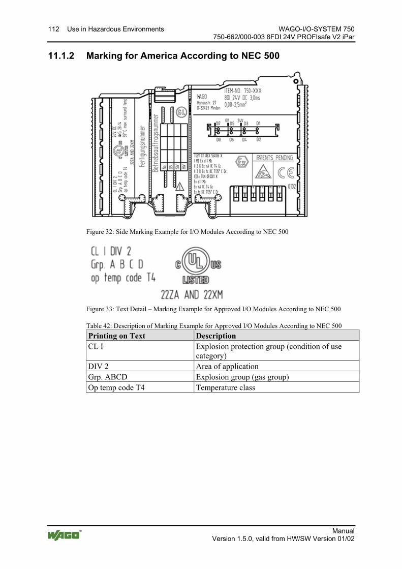
112 Use in Hazardous Environments WAGO-I/O-SYSTEM 750 750-662/000-003 8FDI 24V PROFIsafe V2 iPar
Manual Version 1.5.0, valid from HW/SW Version 01/02
Pos: 57.10 /Serie 750 (WAGO-I/O-SYSTEM)/Einsatz in Ex-Bereichen/Kennzeichnung für Amerika gemäß NEC 500 - Überschrift 3 @ 3\mod_1224158423187_21.docx @ 24188 @ 3 @ 1
11.1.2 Marking for America According to NEC 500 Pos: 57.11 /Serie 750 (WAGO-I/O-SYSTEM)/Einsatz in Ex-Bereichen/Beispielbedruckung gemäß NEC 500_2013 @ 14\mod_1360580302684_21.docx @ 111353 @ @ 1
Figure 32: Side Marking Example for I/O Modules According to NEC 500
Figure 33: Text Detail – Marking Example for Approved I/O Modules According to NEC 500
Table 42: Description of Marking Example for Approved I/O Modules According to NEC 500 Printing on Text Description CL I Explosion protection group (condition of use
category) DIV 2 Area of application Grp. ABCD Explosion group (gas group) Op temp code T4 Temperature class
Pos: 57.12 /Dokumentation allgemein/Gliederungselemente/---Seitenwechsel--- @ 3\mod_1221108045078_0.docx @ 21810 @ @ 1
WAGO-I/O-SYSTEM 750 Use in Hazardous Environments 113 750-662/000-003 8FDI 24V PROFIsafe V2 iPar
Manual Version 1.5.0, valid from HW/SW Version 01/02
Pos: 57.13 /Alle Serien (Allgemeine Module)/Einsatz in Ex-Bereichen/Errichtungsbestimmungen - Überschrift 2 @ 3\mod_1232453624234_21.docx @ 26370 @ 2 @ 1
11.2 Installation Regulations Pos: 57.14 /Alle Serien (Allgemeine Module)/Einsatz in Ex-Bereichen/Errichtungsbestimmungen Einleitung_2013 @ 14\mod_1360582328318_21.docx @ 111371 @ @ 1
For the installation and operation of electrical equipment in hazardous areas, the valid national and international rules and regulations which are applicable at the installation location must be carefully followed.
Pos: 57.15 /Dokumentation allgemein/Gliederungselemente/---Seitenwechsel--- @ 3\mod_1221108045078_0.docx @ 21810 @ @ 1
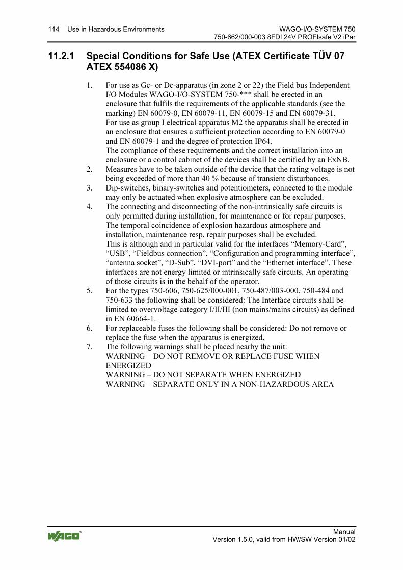
114 Use in Hazardous Environments WAGO-I/O-SYSTEM 750 750-662/000-003 8FDI 24V PROFIsafe V2 iPar
Manual Version 1.5.0, valid from HW/SW Version 01/02
Pos: 57.16 /Serie 750 (WAGO-I/O-SYSTEM)/Einsatz in Ex-Bereichen/Besondere Bedingungen für den sicheren Ex-Betrieb gem. ATEX-Zertifikat TÜV 07 ATEX 554086_X_2013_2 @ 15\mod_1368620071975_21.docx @ 119778 @ 3 @ 1
11.2.1 Special Conditions for Safe Use (ATEX Certificate TÜV 07 ATEX 554086 X)
1. For use as Gc- or Dc-apparatus (in zone 2 or 22) the Field bus Independent I/O Modules WAGO-I/O-SYSTEM 750-*** shall be erected in an enclosure that fulfils the requirements of the applicable standards (see the marking) EN 60079-0, EN 60079-11, EN 60079-15 and EN 60079-31. For use as group I electrical apparatus M2 the apparatus shall be erected in an enclosure that ensures a sufficient protection according to EN 60079-0 and EN 60079-1 and the degree of protection IP64. The compliance of these requirements and the correct installation into an enclosure or a control cabinet of the devices shall be certified by an ExNB.
2. Measures have to be taken outside of the device that the rating voltage is not being exceeded of more than 40 % because of transient disturbances.
3. Dip-switches, binary-switches and potentiometers, connected to the module may only be actuated when explosive atmosphere can be excluded.
4. The connecting and disconnecting of the non-intrinsically safe circuits is only permitted during installation, for maintenance or for repair purposes. The temporal coincidence of explosion hazardous atmosphere and installation, maintenance resp. repair purposes shall be excluded. This is although and in particular valid for the interfaces “Memory-Card”, “USB”, “Fieldbus connection”, “Configuration and programming interface”, “antenna socket”, “D-Sub”, “DVI-port” and the “Ethernet interface”. These interfaces are not energy limited or intrinsically safe circuits. An operating of those circuits is in the behalf of the operator.
5. For the types 750-606, 750-625/000-001, 750-487/003-000, 750-484 and 750-633 the following shall be considered: The Interface circuits shall be limited to overvoltage category I/II/III (non mains/mains circuits) as defined in EN 60664-1.
6. For replaceable fuses the following shall be considered: Do not remove or replace the fuse when the apparatus is energized.
7. The following warnings shall be placed nearby the unit: WARNING – DO NOT REMOVE OR REPLACE FUSE WHEN ENERGIZED WARNING – DO NOT SEPARATE WHEN ENERGIZED WARNING – SEPARATE ONLY IN A NON-HAZARDOUS AREA
Pos: 57.17 /Dokumentation allgemein/Gliederungselemente/---Seitenwechsel--- @ 3\mod_1221108045078_0.docx @ 21810 @ @ 1

WAGO-I/O-SYSTEM 750 Use in Hazardous Environments 115 750-662/000-003 8FDI 24V PROFIsafe V2 iPar
Manual Version 1.5.0, valid from HW/SW Version 01/02
Pos: 57.18 /Serie 750 (WAGO-I/O-SYSTEM)/Einsatz in Ex-Bereichen/Besondere Bedingungen für den sicheren Ex-Betrieb gem. ATEX-Zertifikat TÜV 12 ATEX 106032x_2013_2 @ 15\mod_1368620479454_21.docx @ 119782 @ 3 @ 1
11.2.2 Special Conditions for Safe Use (ATEX Certificate TÜV 12 ATEX 106032 X)
1. For use as Gc- or Dc-apparatus (in zone 2 or 22) the Field bus Independent I/O Modules WAGO-I/O-SYSTEM 750-*** Ex i shall be erected in an enclosure that fulfils the requirements of the applicable standards (see the marking) EN 60079-0, EN 60079-11, EN 60079-15 and EN 60079-31. For use as group I electrical apparatus M2 the apparatus shall be erected in an enclosure that ensures a sufficient protection according to EN 60079-0 and EN 60079-1 and the degree of protection IP64. The compliance of these requirements and the correct installation into an enclosure or a control cabinet of the devices shall be certified by an ExNB.
2. Measures have to be taken outside of the device that the rating voltage is not being exceeded of more than 40 % because of transient disturbances.
3. The connecting and disconnecting of the non-intrinsically safe circuits is only permitted during installation, for maintenance or for repair purposes. The temporal coincidence of explosion hazardous atmosphere and installation, maintenance resp. repair purposes shall be excluded.
4. For the type the following shall be considered: The Interface circuits shall be limited to overvoltage category I/II (non mains/mains circuits) as defined in EN 60664-1.
Pos: 57.19 /Dokumentation allgemein/Gliederungselemente/---Seitenwechsel--- @ 3\mod_1221108045078_0.docx @ 21810 @ @ 1
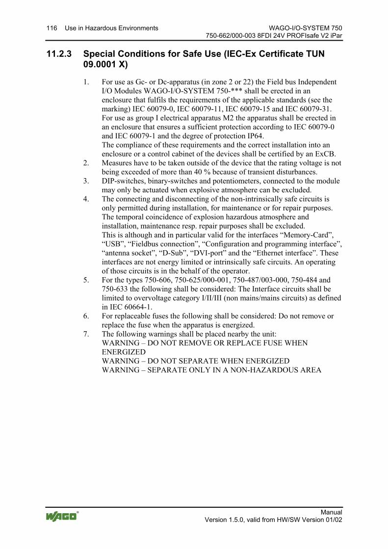
116 Use in Hazardous Environments WAGO-I/O-SYSTEM 750 750-662/000-003 8FDI 24V PROFIsafe V2 iPar
Manual Version 1.5.0, valid from HW/SW Version 01/02
Pos: 57.20 /Serie 750 (WAGO-I/O-SYSTEM)/Einsatz in Ex-Bereichen/Besondere Bedingungen für den sicheren Ex-Betrieb gem. IEC-Ex-Zertifikat TUN 09.0001 X_2013_2 @ 15\mod_1368620660911_21.docx @ 119786 @ 3 @ 1
11.2.3 Special Conditions for Safe Use (IEC-Ex Certificate TUN 09.0001 X)
1. For use as Gc- or Dc-apparatus (in zone 2 or 22) the Field bus Independent I/O Modules WAGO-I/O-SYSTEM 750-*** shall be erected in an enclosure that fulfils the requirements of the applicable standards (see the marking) IEC 60079-0, IEC 60079-11, IEC 60079-15 and IEC 60079-31. For use as group I electrical apparatus M2 the apparatus shall be erected in an enclosure that ensures a sufficient protection according to IEC 60079-0 and IEC 60079-1 and the degree of protection IP64. The compliance of these requirements and the correct installation into an enclosure or a control cabinet of the devices shall be certified by an ExCB.
2. Measures have to be taken outside of the device that the rating voltage is not being exceeded of more than 40 % because of transient disturbances.
3. DIP-switches, binary-switches and potentiometers, connected to the module may only be actuated when explosive atmosphere can be excluded.
4. The connecting and disconnecting of the non-intrinsically safe circuits is only permitted during installation, for maintenance or for repair purposes. The temporal coincidence of explosion hazardous atmosphere and installation, maintenance resp. repair purposes shall be excluded. This is although and in particular valid for the interfaces “Memory-Card”, “USB”, “Fieldbus connection”, “Configuration and programming interface”, “antenna socket”, “D-Sub”, “DVI-port” and the “Ethernet interface”. These interfaces are not energy limited or intrinsically safe circuits. An operating of those circuits is in the behalf of the operator.
5. For the types 750-606, 750-625/000-001, 750-487/003-000, 750-484 and 750-633 the following shall be considered: The Interface circuits shall be limited to overvoltage category I/II/III (non mains/mains circuits) as defined in IEC 60664-1.
6. For replaceable fuses the following shall be considered: Do not remove or replace the fuse when the apparatus is energized.
7. The following warnings shall be placed nearby the unit: WARNING – DO NOT REMOVE OR REPLACE FUSE WHEN ENERGIZED WARNING – DO NOT SEPARATE WHEN ENERGIZED WARNING – SEPARATE ONLY IN A NON-HAZARDOUS AREA
Pos: 57.21 /Dokumentation allgemein/Gliederungselemente/---Seitenwechsel--- @ 3\mod_1221108045078_0.docx @ 21810 @ @ 1
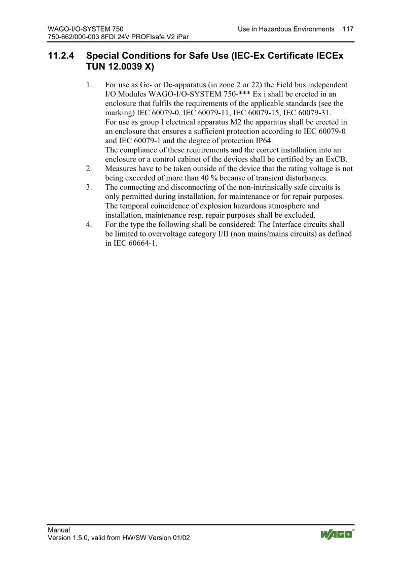
WAGO-I/O-SYSTEM 750 Use in Hazardous Environments 117 750-662/000-003 8FDI 24V PROFIsafe V2 iPar
Manual Version 1.5.0, valid from HW/SW Version 01/02
Pos: 57.22 /Serie 750 (WAGO-I/O-SYSTEM)/Einsatz in Ex-Bereichen/Besondere Bedingungen für den sicheren Ex-Betrieb gem. IEC-Ex-Zertifikat TUN 12.0039 X_2013_2 @ 15\mod_1368620821493_21.docx @ 119790 @ 3 @ 1
11.2.4 Special Conditions for Safe Use (IEC-Ex Certificate IECEx TUN 12.0039 X)
1. For use as Gc- or Dc-apparatus (in zone 2 or 22) the Field bus independent I/O Modules WAGO-I/O-SYSTEM 750-*** Ex i shall be erected in an enclosure that fulfils the requirements of the applicable standards (see the marking) IEC 60079-0, IEC 60079-11, IEC 60079-15, IEC 60079-31. For use as group I electrical apparatus M2 the apparatus shall be erected in an enclosure that ensures a sufficient protection according to IEC 60079-0 and IEC 60079-1 and the degree of protection IP64. The compliance of these requirements and the correct installation into an enclosure or a control cabinet of the devices shall be certified by an ExCB.
2. Measures have to be taken outside of the device that the rating voltage is not being exceeded of more than 40 % because of transient disturbances.
3. The connecting and disconnecting of the non-intrinsically safe circuits is only permitted during installation, for maintenance or for repair purposes. The temporal coincidence of explosion hazardous atmosphere and installation, maintenance resp. repair purposes shall be excluded.
4. For the type the following shall be considered: The Interface circuits shall be limited to overvoltage category I/II (non mains/mains circuits) as defined in IEC 60664-1.
Pos: 57.23 /Dokumentation allgemein/Gliederungselemente/---Seitenwechsel--- @ 3\mod_1221108045078_0.docx @ 21810 @ @ 1

118 Use in Hazardous Environments WAGO-I/O-SYSTEM 750 750-662/000-003 8FDI 24V PROFIsafe V2 iPar
Manual Version 1.5.0, valid from HW/SW Version 01/02
Pos: 57.24 /Serie 750 (WAGO-I/O-SYSTEM)/Einsatz in Ex-Bereichen/Errichtungsbestimmungen ANSI ISA 12.12.01_2013_2 @ 15\mod_1368620942842_21.docx @ 119794 @ 3 @ 1
11.2.5 Special Conditions for Safe Use According to ANSI/ISA 12.12.01
A. “This equipment is suitable for use in Class I, Division 2, Groups A, B, C, D or non-hazardous locations only.”
B. “This equipment is to be fitted within tool-secured enclosures only.” C. “WARNING Explosion hazard - substitution of components may impair
suitability for Class I, Div. 2.” D. “WARNING – Do not disconnect equipment unless power has been
switched off or the area is known to be non-hazardous” has to be placed near each operator accessible connector and fuse holder.
E. When a fuse is provided, the following information shall be provided: “A switch suitable for the location where the equipment is installed shall be provided to remove the power from the fuse.”
F. For devices with EtherCAT/Ethernet connectors “Only for use in LAN, not for connection to telecommunication circuits.”
G. “WARNING - Use Module 750-642 only with antenna module 758-910.” H. For Couplers/Controllers and Economy bus modules only: The instructions
shall contain the following: “The configuration interface Service connector is for temporary connection only. Do not connect or disconnect unless the area is known to be non-hazardous. Connection or disconnection in an explosive atmosphere could result in an explosion.”
I. Modules containing fuses only: “WARNING - Devices containing fuses must not be fitted into circuits subject to over loads, e.g. motor circuits.”
J. Modules containing SD card reader sockets only: “WARNING - Do not connect or disconnect SD-Card while circuit is live unless the area is known to be free of ignitable concentrations of flammable gases or vapors.”
Pos: 57.25 /Dokumentation allgemein/Gliederungselemente/------Leerzeile------ @ 3\mod_1224662755687_0.docx @ 24460 @ @ 1
Pos: 57.26 /Dokumentation allgemein/Gliederungselemente/------Leerzeile------ @ 3\mod_1224662755687_0.docx @ 24460 @ @ 1
Pos: 57.27 /Dokumentation allgemein/Gliederungselemente/------Leerzeile------ @ 3\mod_1224662755687_0.docx @ 24460 @ @ 1
Pos: 57.28 /Serie 750 (WAGO-I/O-SYSTEM)/Einsatz in Ex-Bereichen/Information: Zertifizierungsnachweis @ 7\mod_1274279547729_21.docx @ 56649 @ @ 1
Additional Information Proof of certification is available on request. Also take note of the information given on the operating and assembly instructions. The manual, containing these special conditions for safe use, must be readily available to the user.
Pos: 58 /Dokumentation allgemein/Gliederungselemente/---Seitenwechsel--- @ 3\mod_1221108045078_0.docx @ 21810 @ @ 1
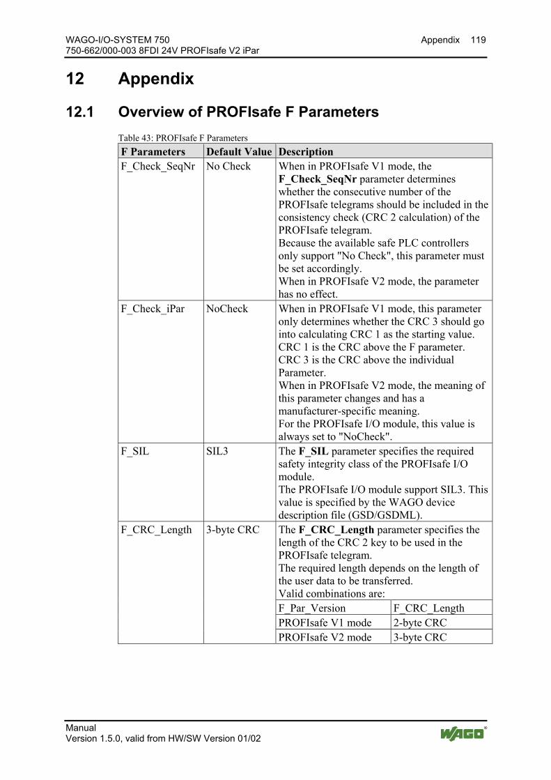
WAGO-I/O-SYSTEM 750 Appendix 119 750-662/000-003 8FDI 24V PROFIsafe V2 iPar
Manual Version 1.5.0, valid from HW/SW Version 01/02
Pos: 59 /Alle Serien (Allgemeine Module)/Überschriften für alle Serien/Anhang - Zubehör/Anhang - Überschrift 1 @ 4\mod_1239874070437_21.docx @ 30560 @ 1 @ 1
12 Appendix Pos: 60 /Serie 750 (WAGO-I/O-SYSTEM)/Anhang/PROFIsafe-F-Parameter 75x-066x/000-003 @ 4\mod_1239798364640_21.docx @ 30511 @ 2 @ 1
12.1 Overview of PROFIsafe F Parameters Table 43: PROFIsafe F Parameters F Parameters Default Value Description F_Check_SeqNr No Check When in PROFIsafe V1 mode, the
F_Check_SeqNr parameter determines whether the consecutive number of the PROFIsafe telegrams should be included in the consistency check (CRC 2 calculation) of the PROFIsafe telegram. Because the available safe PLC controllers only support "No Check", this parameter must be set accordingly. When in PROFIsafe V2 mode, the parameter has no effect.
F_Check_iPar NoCheck When in PROFIsafe V1 mode, this parameter only determines whether the CRC 3 should go into calculating CRC 1 as the starting value. CRC 1 is the CRC above the F parameter. CRC 3 is the CRC above the individual Parameter. When in PROFIsafe V2 mode, the meaning of this parameter changes and has a manufacturer-specific meaning. For the PROFIsafe I/O module, this value is always set to "NoCheck".
F_SIL SIL3 The F_SIL parameter specifies the required safety integrity class of the PROFIsafe I/O module. The PROFIsafe I/O module support SIL3. This value is specified by the WAGO device description file (GSD/GSDML).
F_CRC_Length 3-byte CRC The F_CRC_Length parameter specifies the length of the CRC 2 key to be used in the PROFIsafe telegram. The required length depends on the length of the user data to be transferred. Valid combinations are: F_Par_Version F_CRC_Length PROFIsafe V1 mode 2-byte CRC PROFIsafe V2 mode 3-byte CRC
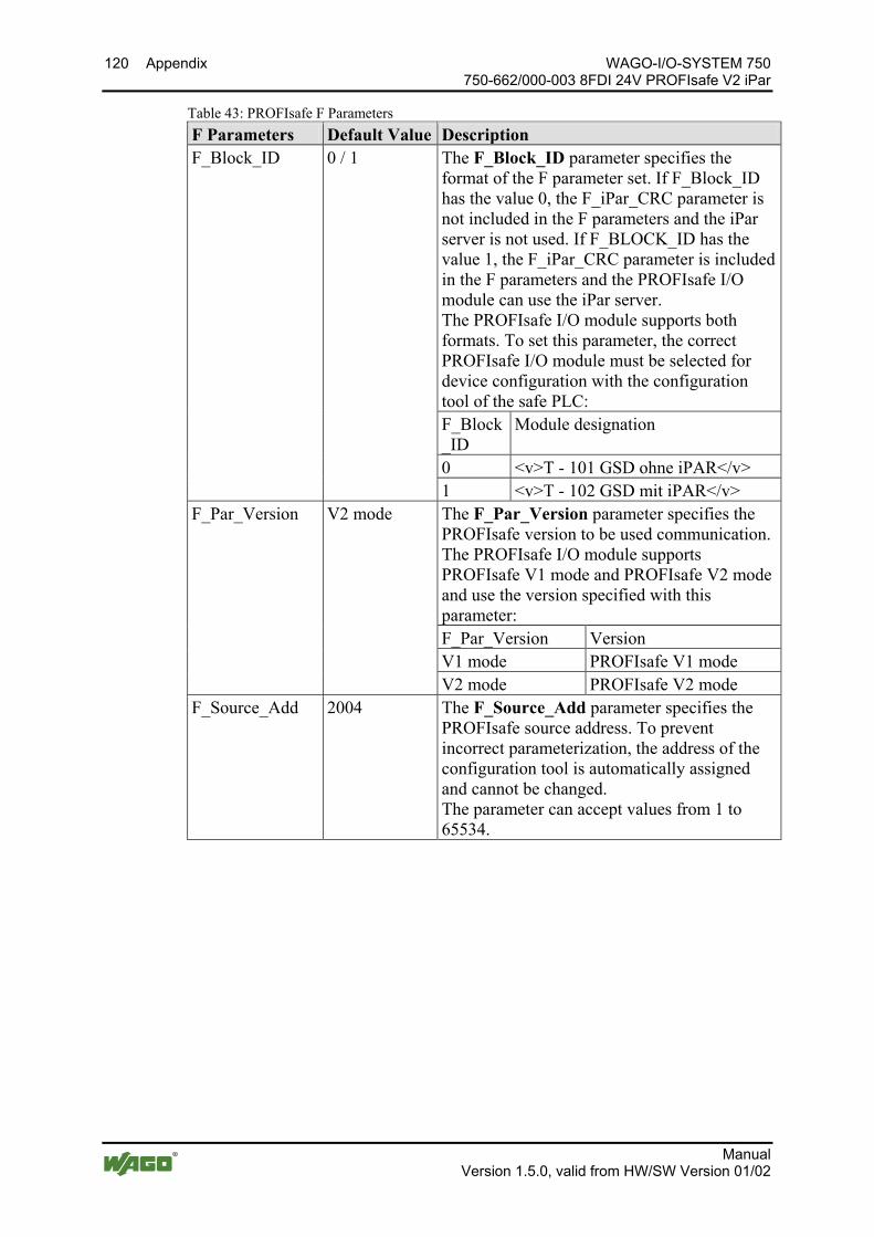
120 Appendix WAGO-I/O-SYSTEM 750 750-662/000-003 8FDI 24V PROFIsafe V2 iPar
Manual Version 1.5.0, valid from HW/SW Version 01/02
Table 43: PROFIsafe F Parameters F Parameters Default Value Description F_Block_ID 0 / 1 The F_Block_ID parameter specifies the
format of the F parameter set. If F_Block_ID has the value 0, the F_iPar_CRC parameter is not included in the F parameters and the iPar server is not used. If F_BLOCK_ID has the value 1, the F_iPar_CRC parameter is included in the F parameters and the PROFIsafe I/O module can use the iPar server. The PROFIsafe I/O module supports both formats. To set this parameter, the correct PROFIsafe I/O module must be selected for device configuration with the configuration tool of the safe PLC: F_Block_ID
Module designation
0 <v>T - 101 GSD ohne iPAR</v> 1 <v>T - 102 GSD mit iPAR</v>
F_Par_Version V2 mode The F_Par_Version parameter specifies the PROFIsafe version to be used communication. The PROFIsafe I/O module supports PROFIsafe V1 mode and PROFIsafe V2 mode and use the version specified with this parameter: F_Par_Version Version V1 mode PROFIsafe V1 mode V2 mode PROFIsafe V2 mode
F_Source_Add 2004 The F_Source_Add parameter specifies the PROFIsafe source address. To prevent incorrect parameterization, the address of the configuration tool is automatically assigned and cannot be changed. The parameter can accept values from 1 to 65534.

WAGO-I/O-SYSTEM 750 Appendix 121 750-662/000-003 8FDI 24V PROFIsafe V2 iPar
Manual Version 1.5.0, valid from HW/SW Version 01/02
Table 43: PROFIsafe F Parameters F Parameters Default Value Description F_Dest_Add 1022 The F_Dest_Add parameter specifies the
PROFIsafe destination address of the PROFIsafe I/O module. For F_Dest_Add, values from 1 to 65534 can be selected. Each address value may appear in the system only once. This is checked by the configuration tool of the safe PLC. For PROFIsafe communication to begin, the parameter value must match the PROFIsafe address of the PROFIsafe I/O module.
F_WD_Time 150 The F_WD_Time parameter determines the monitoring time for PROFIsafe communication between F controller and PROFIbus I/O module. At least one valid PROFIsafe telegram must be exchanged between the safe PLC and the PROFIsafe I/O module within the monitoring time. If this condition is not met, the safe PLC or PROFIsafe I/O module initiates a safe state. The monitoring time must be selected, so that telegram execution times are tolerated, but an interruption in the connection is detected quickly enough. The monitoring time can be specified in steps of 1 ms. The possible value range (50 to 10000 ms) is specified by the WAGO device description file (GSD/GDML).
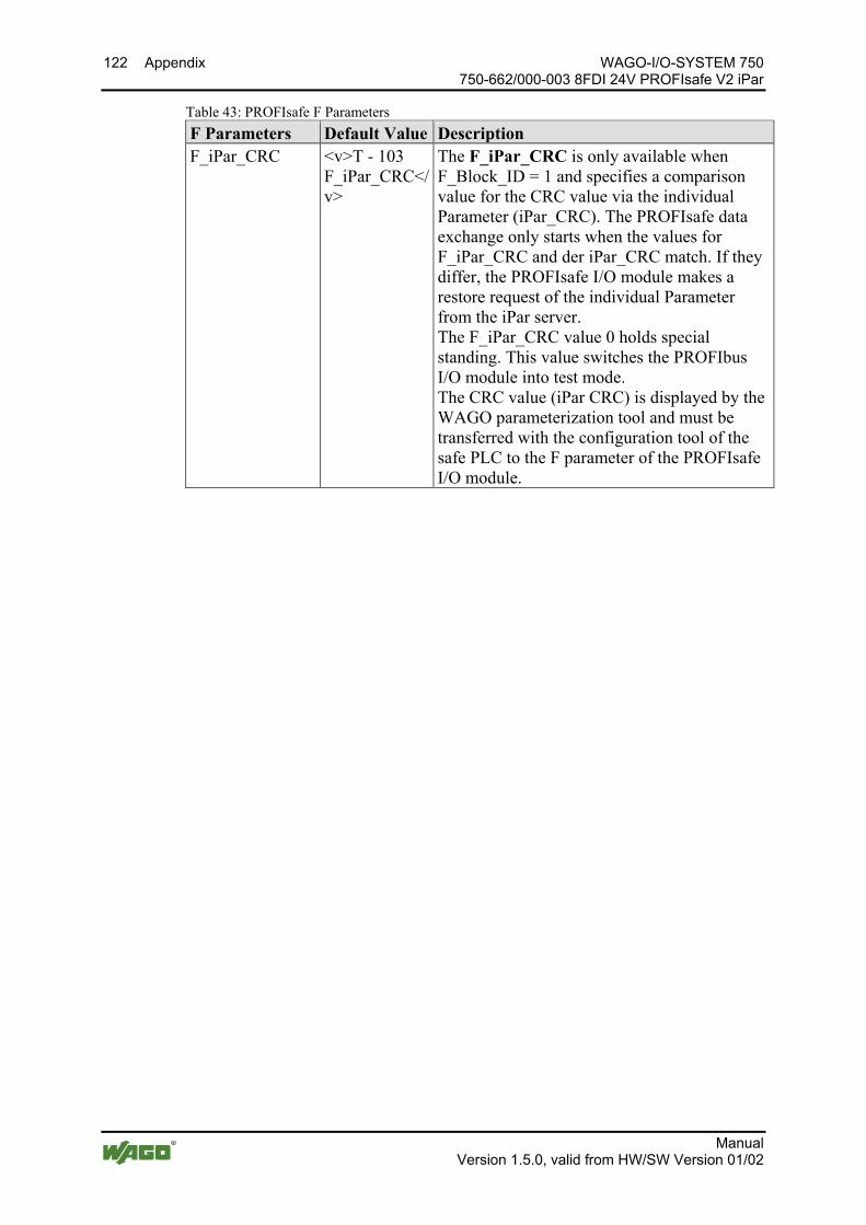
122 Appendix WAGO-I/O-SYSTEM 750 750-662/000-003 8FDI 24V PROFIsafe V2 iPar
Manual Version 1.5.0, valid from HW/SW Version 01/02
Table 43: PROFIsafe F Parameters F Parameters Default Value Description F_iPar_CRC <v>T - 103
F_iPar_CRC</v>
The F_iPar_CRC is only available when F_Block_ID = 1 and specifies a comparison value for the CRC value via the individual Parameter (iPar_CRC). The PROFIsafe data exchange only starts when the values for F_iPar_CRC and der iPar_CRC match. If they differ, the PROFIsafe I/O module makes a restore request of the individual Parameter from the iPar server. The F_iPar_CRC value 0 holds special standing. This value switches the PROFIbus I/O module into test mode. The CRC value (iPar CRC) is displayed by the WAGO parameterization tool and must be transferred with the configuration tool of the safe PLC to the F parameter of the PROFIsafe I/O module.
Pos: 61 /Dokumentation allgemein/Gliederungselemente/---Seitenwechsel--- @ 3\mod_1221108045078_0.docx @ 21810 @ @ 1

WAGO-I/O-SYSTEM 750 Appendix 123 750-662/000-003 8FDI 24V PROFIsafe V2 iPar
Manual Version 1.5.0, valid from HW/SW Version 01/02
Pos: 62 /Serie 750 (WAGO-I/O-SYSTEM)/Anhang/PROFIsafe-Zertifikate 75x-066x @ 4\mod_1235470780343_21.docx @ 27654 @ 2 @ 1
12.2 PROFIsafe Certificates
PROFIsafe Certificates A list of PROFIsafe certificates and PDFs of the certificates are available on the "AUTOMATION Tools and Docs" DVD-ROM (Art. No.: 0888-0412) or on the Internet at: http://www.wago.com/ Documentation WAGO I/O SYSTEM 750 or WAGO I/O SYSTEM 753 PROFIsafe Safety Modules More Information Certificates.
Pos: 63 /Dokumentation allgemein/Gliederungselemente/---Seitenwechsel--- @ 3\mod_1221108045078_0.docx @ 21810 @ @ 1
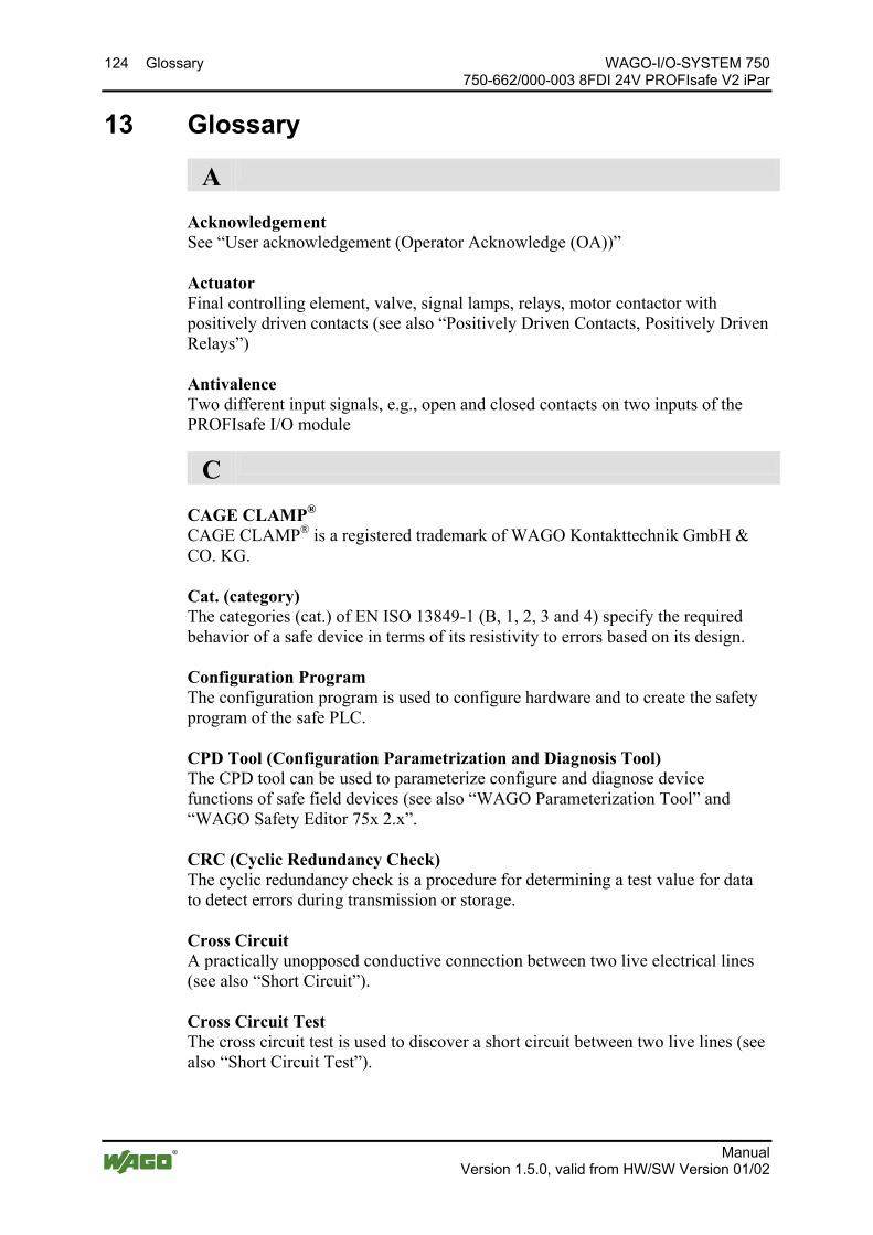
124 Glossary WAGO-I/O-SYSTEM 750 750-662/000-003 8FDI 24V PROFIsafe V2 iPar
Manual Version 1.5.0, valid from HW/SW Version 01/02
Pos: 64 /Dokumentation allgemein/Verzeichnisse/Glossar - Überschrift 1 @ 7\mod_1265811387961_21.docx @ 50272 @ 1 @ 1
13 Glossary Pos: 65 /Serie 750 (WAGO-I/O-SYSTEM)/Glossar/Glossar - PROFIsafe 75x-66x @ 7\mod_1265811258836_21.docx @ 50269 @ @ 1
A
Acknowledgement See “User acknowledgement (Operator Acknowledge (OA))” Actuator Final controlling element, valve, signal lamps, relays, motor contactor with positively driven contacts (see also “Positively Driven Contacts, Positively Driven Relays”) Antivalence Two different input signals, e.g., open and closed contacts on two inputs of the PROFIsafe I/O module
C
CAGE CLAMP® CAGE CLAMP® is a registered trademark of WAGO Kontakttechnik GmbH & CO. KG. Cat. (category) The categories (cat.) of EN ISO 13849-1 (B, 1, 2, 3 and 4) specify the required behavior of a safe device in terms of its resistivity to errors based on its design. Configuration Program The configuration program is used to configure hardware and to create the safety program of the safe PLC. CPD Tool (Configuration Parametrization and Diagnosis Tool) The CPD tool can be used to parameterize configure and diagnose device functions of safe field devices (see also “WAGO Parameterization Tool” and “WAGO Safety Editor 75x 2.x”. CRC (Cyclic Redundancy Check) The cyclic redundancy check is a procedure for determining a test value for data to detect errors during transmission or storage. Cross Circuit A practically unopposed conductive connection between two live electrical lines (see also “Short Circuit”). Cross Circuit Test The cross circuit test is used to discover a short circuit between two live lines (see also “Short Circuit Test”).

WAGO-I/O-SYSTEM 750 Glossary 125 750-662/000-003 8FDI 24V PROFIsafe V2 iPar
Manual Version 1.5.0, valid from HW/SW Version 01/02
D
Dangerous Failure Termination of the capacity of a unit to complete the required function (see also “Failure”). DC (Diagnostic Coverage) The diagnostic coverage is the decrease in probability of dangerous hardware failures that result from executing automatic diagnostics tests. DC13 (Utilization Category) Utilization category DC13 of EN 60947-5-1 describes the making and breaking capacity for switching elements to apply an electromagnetic load. Default Individual Parameter Set A data set persistently stored in the PROFIsafe I/O module with default values that correspond to the individual parameter set in the delivery condition of the PROFIsafe I/O module Diagnostic Coverage Level See “DC (Diagnostic Coverage)” Discrepancy Time The discrepancy time specifies the maximum permissible duration of unequal states of two signals. See also “Discrepancy Time Monitoring” Discrepancy Time Monitoring Discrepancy time monitoring is performed by the PROFIsafe I/O module when using the two-channel analysis by comparing the signal states of two digital inputs against the valence rule. If the inputs signals deviate from the valence rule, discrepancy time monitoring is activated (see also “Discrepancy Time”).
E
Equivalence Two same input signals, e.g., two open contacts on two inputs of the PROFIsafe I/O module
F
F parameters Parameters for configuring data communication between the safe PLC and the PROFIsafe I/O module Failure Termination of the capacity of a unit to complete the required function (see also “Dangerous failure”).
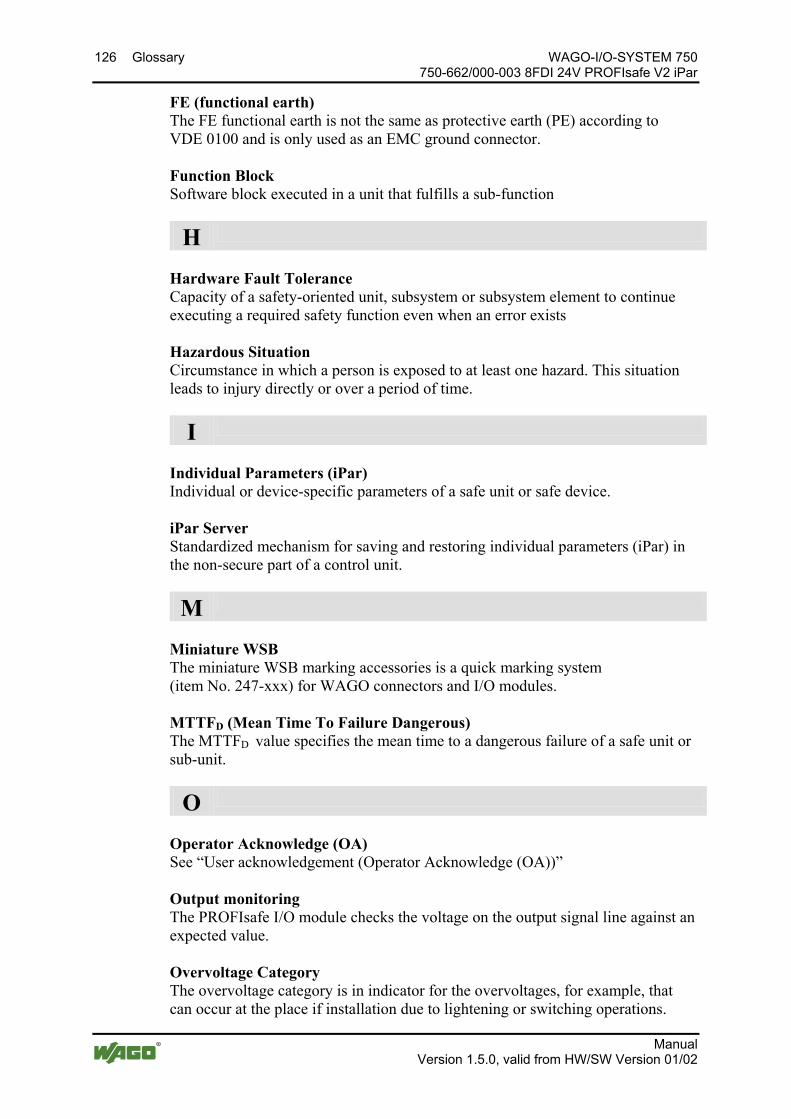
126 Glossary WAGO-I/O-SYSTEM 750 750-662/000-003 8FDI 24V PROFIsafe V2 iPar
Manual Version 1.5.0, valid from HW/SW Version 01/02
FE (functional earth) The FE functional earth is not the same as protective earth (PE) according to VDE 0100 and is only used as an EMC ground connector. Function Block Software block executed in a unit that fulfills a sub-function
H
Hardware Fault Tolerance Capacity of a safety-oriented unit, subsystem or subsystem element to continue executing a required safety function even when an error exists Hazardous Situation Circumstance in which a person is exposed to at least one hazard. This situation leads to injury directly or over a period of time.
I
Individual Parameters (iPar) Individual or device-specific parameters of a safe unit or safe device. iPar Server Standardized mechanism for saving and restoring individual parameters (iPar) in the non-secure part of a control unit.
M
Miniature WSB The miniature WSB marking accessories is a quick marking system (item No. 247-xxx) for WAGO connectors and I/O modules. MTTFD (Mean Time To Failure Dangerous) The MTTFD value specifies the mean time to a dangerous failure of a safe unit or sub-unit.
O
Operator Acknowledge (OA) See “User acknowledgement (Operator Acknowledge (OA))” Output monitoring The PROFIsafe I/O module checks the voltage on the output signal line against an expected value. Overvoltage Category The overvoltage category is in indicator for the overvoltages, for example, that can occur at the place if installation due to lightening or switching operations.
WAGO-I/O-SYSTEM 750 Glossary 127 750-662/000-003 8FDI 24V PROFIsafe V2 iPar
Manual Version 1.5.0, valid from HW/SW Version 01/02
P
Passivate, passivation Passivation of safe digital inputs or power outputs is performed automatically by the PROFIsafe I/O module after activation or detection of errors. Operator acknowledgement is required after passivation, so that the PROFIsafe I/O module can start. PE (Protective Earth) The PE is connected to the ground connector according to EN 60204-1 and is used as fundamental protection against electric shock when touched indirectly. It is also used to reduce the effect of electrical interference on electrical equipment that affect operation of a machine or system. PFD (Probability of Failure on Demand) The safety parameter PFD specifies the probability of a dangerous failure. PFH (Probability of dangerous Failure per Hour) The safety parameter PFH specifies the probability of a dangerous failure within one error. PL (Performance Level) The Performance Level PL specifies the capacity of safety devices to execute a safety function under foreseeable conditions. PLC A PLC (Programmable Logic Controller) is a device used to control a machine or system and is programmed on a digital basis.Requirement Event that the PROFIsafe I/O module causes to execute its safety function Positively driven contacts, positively driven relays Positively driven contacts or positively driven operation means that break contacts and make contacts can never be opened or closed at the same time in a contact system. It must be ensured that a contact gap of min. 0.5 mm is present throughout the service life and in the faulted state (contact welding). Relays with positively driving contacts are normative elementary relays according to IEC EN 61810-1 with special additional properties based on the contact set, whose requirements are formulated in EN 50205 (see also “Actuator”). PROFIsafe Safety-oriented data communication via the standard PROFIBUS or PROFINET (black channel). A distinction is made between V1 mode and V2 mode. PROFIsafe V1 Mode acc. IEC 61784-3-3 PROFIsafe V1 Mode – Services and protocols of the safety-oriented PROFIsafe communication profile according to PROFIBUS Guideline: PROFIsafe – Profile for Safety Technology, V1.30, June 2004.

128 Glossary WAGO-I/O-SYSTEM 750 750-662/000-003 8FDI 24V PROFIsafe V2 iPar
Manual Version 1.5.0, valid from HW/SW Version 01/02
PROFIsafe V2 Mode acc. IEC 61784-3-3 PROFIsafe V2 Mode – Services and protocols of the safety-oriented PROFIsafe communication profile according to PROFIBUS Guideline: PROFIsafe – Profile for Safety Technology, 2.4, March 2007. PROFIsafe Address Address that must be assigned to a safe device with PROFIsafe data communication, so that data communication can be established between a PROFIsafe master and a PROFIsafe slave. Proof Test Proof test or recurring test that is performed to discover failures in a safety-related system, so that the system can be brought to a "like-new state" or as close as possible to this state from a practical perspective. Proof Test Interval The proof test interval is the time until testing the safety function / safety device is required. Protected Installation The goal of the protected installation of lines is, for example, operational reliability and protection against vagabond voltages at different voltages in a cable or equipment. Among other means, this is achieved by the necessary insulation between two lines of different potentials.
R
Request duration Minimum duration of a signal voltage “0” (e.g., open input) on the input of the PROFIsafe I/O module Requirement Event that the PROFIsafe I/O module causes to execute its safety function Restart Barrier A restart barrier is a means of preventing hazardous machine operation from starting automatically after one or more of the following events: - Triggering of a safety function - Changing of the operating mode of the machine - Changing of the means for staring the machine Risk Reduction The required risk reduction is the result of a risk assessment that is used to take measures to lower the risk of a security system to an acceptable residual risk.
WAGO-I/O-SYSTEM 750 Glossary 129 750-662/000-003 8FDI 24V PROFIsafe V2 iPar
Manual Version 1.5.0, valid from HW/SW Version 01/02
S
Safe PLC A safe PLC (Programmable Logic Controller) is a safety-oriented PLC that controls safe devices such as PROFIsafe I/O modules. Safety Function Function of a machine whose failure can lead to an immediate increase in the risk(s). Sensor A sensor is used to capture physical units (e.g., switch setting, temperature, pressure, etc.) and can be connected (if compatible) to the digital inputs of the PROFIsafe I/O module. Short Circuit A practically unopposed conductive connection between two live electrical lines (see also “Cross Circuit”). Short Circuit Test The short-circuit test is used to discover a short circuit between two live lines. See also “Cross Circuit Test”. SIL (Safety Integrity Level) The Safety Integrity Level (SIL) is used to assess electrical/electronic/programmable electronic (E/E/PE) systems in terms of reliability of safety functions. There are four levels for specifying the requirement for the safety integrity of safety functions where “Safety Integrity Level 4” is the highest level of safety integrity and “Safety Integrity Level 1” is the lowest. Single Fault Security Even after an error occurs, the required safety function is still ensured. In other words, an error does not lead to the loss of the safety function.
T
TCI (Tool Calling Interface) TCI (Tool Calling Interface) is an interface specified by the PROFIBUS User Organization (PNO), which defines how device-specific or manufacturer-specific parameterization tools are called from a configuration environment. The features of the interface are described in conformance classes. Generally, the communication options of the specific software tools are determined with the devices.
130 Glossary WAGO-I/O-SYSTEM 750 750-662/000-003 8FDI 24V PROFIsafe V2 iPar
Manual Version 1.5.0, valid from HW/SW Version 01/02
Test Mode The test mode is intended for starting up and configuring the PROFIsafe I/O module with the iPar server and is initiated by the PROFIsafe I/O module upon receiving the F parameter F_iPar_CRC = 0. This eliminates the check of F_iPar_CRC against iPar_CRC. All digital inputs and power outputs are passivated during test mode and the PROFIsafe I/O module outputs the substitute values (failsafe values) instead of actual process values to the controller. According to the PROFIsafe specification, the test mode is indicated visually by 2 Hz flashing of the parameterization LED (LED H) in green on the PROFIsafe I/O module.
U
User acknowledgement (Operator Acknowledge (OA)) Prompt for user acknowledgement (operator acknowledgement) that evokes start-up of a machine or system.. User acknowledgement is necessary for the PROFIsafe I/O module, for example, after detecting errors by the PROFIsafe I/O module and their resolution by maintenance personnel and is initiated from the control level.
V
Valence Analysis The valence analysis is the analysis of two input signals either according to the rules of equivalence (equality) or according to the rules of antivalence (difference).
W
WAGO Parameterization Tool The WAGO parameterization tool is required to configure the PROFIsafe I/O module. This refers to the WAGO-I/O-CHECK 3.x and WAGO Safety Editor 75x 2.x manufacturer tools (see also “WAGO-I/O-CHECK”). WAGO Safety Editor 75x 2.x The WAGO Safety Editor (SEDI) 75x 2.x is required together with the WAGO-I/O-CHECK 3.x to configure the PROFIsafe I/O module. SEDI is the CPD tool for WAGO PROFIsafe I/O modules (see also “CPD Tool (Configuration Parametrization and Diagnosis Tool)”). WAGO-I/O-CHECK WAGO-I/O-CHECK is a manufacturer tool used to configure WAGO I/O modules. To parameterize the PROFIsafe I/O modules, WAGO-I/O-CHECK 3.x and WAGO Safety Editor 75x 2.x are required (see also “WAGO Parameterization Tool”).
=== Ende der Liste für Textmarke Inhalt_mitte ===
WAGO-I/O-SYSTEM 750 List of Figures 131 750-662/000-003 8FDI 24V PROFIsafe V2 iPar
Manual Version 1.5.0, valid from HW/SW Version 01/02
Pos: 67 /Dokumentation allgemein/Verzeichnisse/Abbildungsverzeichnis - Überschrift oG und Verzeichnis @ 3\mod_1219222916765_21.docx @ 21080 @ @ 1
List of Figures Figure 1: Mixed Operation of Safety-Related and Non-Safety-Related
I/O Modules ................................................................................................. 16 Figure 2: PROFIsafe Layer Model ........................................................................ 17 Figure 3: iPar Server .............................................................................................. 18 Figure 4: View ....................................................................................................... 22 Figure 5: Data Contacts ......................................................................................... 23 Figure 6: Power Jumper Contacts ......................................................................... 24 Figure 7: CAGE CLAMP® Connectors................................................................. 26 Figure 8: Display Elements, Inputs 1 ... 4 ............................................................. 27 Figure 2: Display Elements, Inputs 5 … 8 ............................................................ 28 Figure 10: Display Elements, Communication/ I/O Module Status ...................... 29 Figure 11: Coding Switch for the PROFIsafe Address (set to 1018) .................... 31 Figure 12: Schematic Diagram .............................................................................. 32 Figure 13: Input Block Diagram ........................................................................... 32 Figure 14: Insert I/O Module (Example) ............................................................... 52 Figure 15: Snap the I/O Module into Place (Example) ......................................... 52 Figure 16: Removing the I/O Module (Example) ................................................. 53 Figure 17: Connecting a Conductor to a CAGE CLAMP® ................................... 54 Figure 18: Infeed for PROFIsafe I/O Modules 750-66x and 753-66x .................. 56 Figure 19: Infeed for PROFIsafe I/O Modules 75x-66x with
Backup Capacitor Module 288-824 ............................................................. 57 Figure 20: Connection 8 x Emergency Off, Single-Channel,
Short Circuit Test Active ............................................................................. 60 Figure 21: Connection 8 x Emergency Off, Single-Channel,
Short Circuit Test Not Active ...................................................................... 61 Figure 22: Connection 4 x Emergency-Off Switch, Dual Channel,
Equivalent Evaluation .................................................................................. 62 Figure 23: Connection 2 x Interlock Monitoring, Dual Channel,
Antivalent Evaluation .................................................................................. 64 Figure 24: Connection 2 x Mode Selector Switch ................................................ 65 Figure 25: Example of a Serial Number ................................................................ 67 Figure 26: Schematic Representation for User Acknowledgement
via “OA_Req” ............................................................................................ 101 Figure 27: Schematic Representation for User Acknowledgement
via “OA_Req” and “F_Ack” ...................................................................... 102 Figure 28: Side Marking Example for Approved I/O Modules
According to ATEX and IECEx ................................................................ 107 Figure 29: Text Detail – Marking Example for Approved I/O Modules
According to ATEX and IECEx. ............................................................... 107 Figure 30: Side Marking Example for Approved Ex i I/O Modules
According to ATEX and IECEx. ............................................................... 109 Figure 31: Text Detail – Marking Example for Approved Ex i I/O Modules
According to ATEX and IECEx. ............................................................... 109 Figure 32: Side Marking Example for I/O Modules According to NEC 500 ..... 112 Figure 33: Text Detail – Marking Example for Approved I/O Modules
According to NEC 500............................................................................... 112
Pos: 68 /Dokumentation allgemein/Gliederungselemente/---Seitenwechsel--- @ 3\mod_1221108045078_0.docx @ 21810 @ @ 1
132 List of Tables WAGO-I/O-SYSTEM 750 750-662/000-003 8FDI 24V PROFIsafe V2 iPar
Manual Version 1.5.0, valid from HW/SW Version 01/02
Pos: 69 /Dokumentation allgemein/Verzeichnisse/Tabellenverzeichnis - Überschrift oG und Verzeichnis @ 3\mod_1219222958703_21.docx @ 21084 @ @ 1
List of Tables Table 1: Number Notation ..................................................................................... 11 Table 2: Font Conventions .................................................................................... 11 Table 3: Legend for the iPar Server Figure ........................................................... 18 Table 4: Legend for Figure “View” ...................................................................... 22 Table 5: Legend for Figure “Power Jumper Contacts” ......................................... 24 Table 6: Legend for Figure “CAGE CLAMP® Connectors” ................................ 26 Table 7: Legend for Figure “Display Elements, Inputs 1 ... 4” ............................. 27 Table 1: Legend for Figure “Display Elements, Inputs 5 … 8” ............................ 28 Table 9: Legend for Figure “Display Elements, Communication /
I/O Module Status” ...................................................................................... 29 Table 10: Technical Data, Device Data ................................................................. 33 Table 11: Technical Data, Power Supply .............................................................. 33 Table 12: Technical Data, Communication ........................................................... 34 Table 13: Technical Data, Digital Inputs .............................................................. 35 Table 14: Technical Data, Digital Clock Outputs ................................................. 36 Table 15: Technical Data, Clock Pulse Duration at Input Filter Time .................. 36 Table 16: Safety Parameters for 2-Channel
Safety Applications – 10 Years .................................................................... 37 Table 17: Safety Parameters for 2-Channel
Safety Applications – 20 Years .................................................................... 38 Table 18: Safety Parameters for Single-Channel
Safety Application – 10 Years ..................................................................... 39 Table 19: Safety Parameters for Single-Channel
Safety Application – 20 Years ..................................................................... 40 Table 20: Technical Data – Field Wiring .............................................................. 41 Table 21: Technical Data – Power Jumper Contacts ............................................ 41 Table 22: Technical Data – Data Contacts ............................................................ 41 Table 23: Technical Data – Climatic Environmental Conditions ......................... 41 Table 24: Safe Response Time of the Digital Inputs
in the Event of Failure .................................................................................. 43 Table 25: Safe Response Time of the Digital Inputs
in the Error-Free Operation .......................................................................... 44 Table 26: Process Image PROFIsafe V1 Mode ..................................................... 49 Table 27: PROFIsafe Inputs, V1 Mode ................................................................. 49 Table 28: PROFIsafe Outputs, V1 Mode .............................................................. 49 Table 29: Process Image PROFIsafe V2 Mode ..................................................... 50 Table 30: PROFIsafe Inputs, V2 Mode ................................................................. 50 Table 31: PROFIsafe Outputs, V2 Mode .............................................................. 50 Table 32: Adjustable Parameters ........................................................................... 77 Table 33: Input Pulse Durations Depending on the Input Filter Time .................. 78 Table 34: Input Assignment − Clock Outputs ....................................................... 79 Table 35: Error Detection ...................................................................................... 80 Table 36: Antivalent Evaluation ............................................................................ 85 Table 37: Equivalent Evaluation ........................................................................... 86 Table 38: Necessary Signal States for Acknowledgement
if the Restart Inhibit is Set to "Yes" ............................................................. 87 Table 39: Diagnostic Messages ............................................................................. 95
WAGO-I/O-SYSTEM 750 List of Tables 133 750-662/000-003 8FDI 24V PROFIsafe V2 iPar
Manual Version 1.5.0, valid from HW/SW Version 01/02
Table 40: Description of Marking Example for Approved I/O Modules According to ATEX and IECEx ................................................................ 108
Table 41: Description of Marking Example for Approved Ex i I/O Modules According to ATEX and IECEx ................................................................ 110
Table 42: Description of Marking Example for Approved I/O Modules According to NEC 500............................................................................... 112
Table 43: PROFIsafe F Parameters ..................................................................... 119
=== Ende der Liste für Textmarke Verzeichnis_hinten ===

Pos: 71 /Dokumentation allgemein/Einband/Einband Handbuch - Leerseite für durch 2 teilbare Seitenzahl (Standarddruck) @ 3\mod_1219230851078_0.docx @ 21123 @ @ 1 Pos: 72 /Dokumentation allgemein/Einband/Einband Handbuch - Rückseite 2015 @ 9\mod_1285229376516_21.docx @ 64944 @ @ 1
WAGO Kontakttechnik GmbH & Co. KG Postfach 2880 • D-32385 Minden Hansastraße 27 • D-32423 Minden Phone: 05 71/8 87 – 0 Fax: 05 71/8 87 – 1 69 E-Mail: [email protected] Internet: http://www.wago.com
=== Ende der Liste für Textmarke Einband_hinten ===