Manpower Planning and Cycle-Time Reduction
56
Manpower Planning and Cycle-Time Reduction of a Labor-Intensive Assembly Line By Shao Chong Oh B.Eng. Mechanical Engineering (Mechatronics) 2009 Nanyang Technological University, Singapore MASSACHUSETTS INSTITUTE OF TECHY4 'OLOGY NOV 0 4 2010 LIBRARIES ARCHIVES SUBMITTED TO THE DEPARTMENT OF MECHANICAL ENGINEERING IN PARTIAL FULFILLMENT OF THE REQUIREMENT FOR THE DEGREE OF MASTER OF ENGINEERING IN MANUFACTURING AT THE MASSACHUSETTS INSTITUTE OF TECHNOLOGY SEPTEMBER 2010 C 2010 Massachusetts Institute of Technology. All rights reserved. Signature of Author: S. Department of Mechanical Engineering August 6, 2010 ,,1 /1 Certified by: Stephen C. Graves Abraham J. Siegel Professor of Management Science Department of Mechanical Engineering and Engineering Systems Thesis Supervisor Accepted by: David E. Hardt Ralph E. and Eloise F. Cross Professor of Mechanical Engineering Chairman, Committee on Graduate Students - I
Transcript of Manpower Planning and Cycle-Time Reduction
Manpower Planning and Cycle-Time Reduction
of a Labor-Intensive Assembly Line
By
Shao Chong Oh
B.Eng. Mechanical Engineering (Mechatronics) 2009Nanyang Technological University, Singapore
MASSACHUSETTS INSTITUTEOF TECHY4 'OLOGY
NOV 0 4 2010
LIBRARIES
ARCHIVES
SUBMITTED TO THE DEPARTMENT OF MECHANICAL ENGINEERING INPARTIAL FULFILLMENT OF THE REQUIREMENT FOR THE DEGREE OF
MASTER OF ENGINEERING IN MANUFACTURINGAT THE
MASSACHUSETTS INSTITUTE OF TECHNOLOGY
SEPTEMBER 2010
C 2010 Massachusetts Institute of Technology. All rights reserved.
Signature of Author:
S.
Department of Mechanical EngineeringAugust 6, 2010
,,1 /1
Certified by:Stephen C. Graves
Abraham J. Siegel Professor of Management ScienceDepartment of Mechanical Engineering and Engineering Systems
Thesis Supervisor
Accepted by:David E. Hardt
Ralph E. and Eloise F. Cross Professor of Mechanical EngineeringChairman, Committee on Graduate Students
- I

[This page is intentionally left blank]

Manpower Planning and Cycle-time Reduction
of a Labor-Intensive Assembly Line
]By
Shao Chong Oh
Submitted to the Department of Mechanical Engineering
on August 6, 2010
in Partial Fulfillment of the Requirements for the
Degree of Master of Engineering in Manufacturing
Abstract
The demand for Gas Lift Mandrels(GLM) in the oil and gas industry is expected to increase over the next
few years, requiring Schlumberger's GLM assembly line to increase their manufacturing capacity. Given
the labor-intensive nature of Schlumberger's GLM assembly line, other than implementing kaizens and
purchasing more equipment, it is important to also consider manpower issues. This research analyzesmanpower management issues in the GLM assembly line to meet the projected increase in customer
demand over the next three years.
A detailed time study was conducted to understand and characterize all processes in the assembly line,before manpower plans were drawn up for each year till 2013. Several manpower scheduling conceptswere incorporated in the manpower plan, such as Job Rotation and Workforce Flexibility to optimize therate of utilization, human performance and well-being. By clustering processes together, the labor
utilization rate can be increased to more than ninety percent. A new position of grinders has also beenproposed to assist in various grinding operations, in order to reduce the cycle times of processes, to helpworkers gain better focus in their work and to reduce the cost of labor.
Disclaimer: All numerical data and results presented have been manipulated to protect the confidentiality
of the company.
Keywords:
Gas Lift Mandrels(GLM), workforce flexibility, manpower planning/scheduling
Thesis Supervisor: Stephen C. Graves
Title: Professor, Department of Mechanical Engineering

[This page is intentionally left blank]

ACKNOWLEDGEMENTI would like to express my deepest gratitude to my thesis advisor, Professor Stephen C. Graves,
for all his advices and support throughout the course of this project. He has tirelessly and
patiently guided me along the way, enabling me to achieve one milestone after another, till all
the objectives of the project have been achieved. I would also like to thank Professor Graves for
screening through this report in every single detail possible.
I am also grateful to Dr. Brian W. Anthony for all his effort in coordinating this project with
Schlumberger. Without him, this project would not have been possible in the first place.
I would like to extend my sincere appreciation to Schlumberger for sponsoring this work. My
company supervisor, Mr Dominic Pey, has never failed to patiently provide encouragements and
guidance for the past eight months. Dr. Yang Rongling, the department's LSS Champion, has
generously invited us to her courses on LSS and clarified many conceptual doubts that I had. I
would also like to thank all the employees at different levels who have selflessly helped me with
information collection and developing a better understanding of the facility.
Special thanks go to Ms. Jennifer Craig for reviewing this thesis and providing valuable
technical writing advice.
Last but not least, I would like to thank my project teammates for their valuable feedback and
suggestions. They have made this project both fruitful and memorable to me.

TABLE OF CONTENTSS In tro d u ctio n................................................................................................................................... 10
1.1 Company Background............................................................................................................ 10
1.2 Product Description................................................................................................................ 10
1.3 Gas Lift M andrel M anufacturing Process.......... ......................... .................................... 12
1.4 Current M anufacturing Issues.............................................................................................. 14
2 Problem Statement......................................................................................................................... 16
2.1 Introduction ............................................................. 16
2.2 The Process Flow ................................................................................................................... 16
2.3 Characterization of the Assembly Line ................................................................................ 17
2.4 Objectives and Scope ...................................................... 20
3 Literature Review .......................................................................................................................... 21
3 .1 T a k t tim e ................................................................................................................................ 2 1
3.2 W orkforce Flexibility.............................................................................................................21
3.3 Job Rotation Scheduling.................................................................................................... 21
3.4 M athematical modeling for workforce flexibility................................................................. 22
4 M eth o do lo gy ................................................................................................................................. 2 3
4.1 Data Collection and Analysis ............... ............................................ 23
4.2 Proportion of productive working hours ................ ..................... ..................................... 24
4.3 Planned Cycle Time .............................................................................................................. 25
4.4 Formulation of manpower plans .......................................... 25
5 Results and Discussion .................................................................................................................. 27
5.1 Proportion of productive working hours ............. ... .............. ............... ........ 27
5.2 Planned cycle time analysis ............................................................................................... 27
5.3 Average manual work content of each process...................................... 31

5.4 Baseline analysis.................................................................................................................... 32
5.5 Employm ent and deploym ent of workers............................................................................. 34
5.6 M anpower plan for 2011 ........................................................................................ ..... 36
5.7 M anpower plan for 2012........................................................................................................38
5.8 M anpower plan for 2013 ........................................................................................................ 39
5.9 Evaluation of proposed manpower plans............................................................................. 41
6 Recomm endations ........................................................................................................................ 43
6.1 Summary of M anpower Plan .............................................................................................. 43
6.2 Cycle tim e reduction at Cold Straightening.......................................................................... 44
6.2.1 Problem .......................................................................................................................... 44
6.2.2 Recomm endations .......................................................................................................... 44
6.3 Cycle tim e reduction at OD Drift............ ................ ..................... 44
6.3.1 Problem .......................................................................................................................... 44
6.3.2 Recomm endations .......................................................................................................... 45
6.4 Verifying part routings before comm encing operations....................................................... 45
6.4.1 Problem .......................................................................................................................... 45
6.4.2 Possible causes ............................................................................................................... 45
6.4.3 Recomm endations .......................................................................................................... 46
7 Conclusion .................................................................................................................................... 47
7.1 Conclusion............................................................................................................................. 47
7.2 Future W ork........................................................................................................................... 47
R eferen c e s............................................................................................................................................. 4 9
Appendix I - Compiled data of GLM assembly processes...................................................................... 50
Appendix II - Spreadsheet calculations of m anpower plans ................................................................. 55

LIST OF FIGURES
Figure 1-1: A Gas Lift M andrel (GLM ) in operation[ 1].......................................................................... I1
Figure 1-2: Components of standard round mandrels ........................................................................ 12
Figure 1-3: Components of long round mandrels................................................................................ 12
Figure 1-4: Com ponents of an oval m andrel....................................................................................... 12
Figure 1-5: General process flow chart of GLM production line for oval and round mandrels........ 12
Figure 1-6: A long round mandrel that is made up of four components............. ............. 14
Figure 2-1: Process flow of oval m andrels[2]...................................................................................... 17
Figure 2-2: Process flow of round m andrels ...................................................................................... 17
Figure 2-3: First Pass Yield percentage of mandrels at each inspection station[3] ........... ..... 18
Figure 5-1: Breakdown of working hours for a normal shift .............................................................. 27
Figure 5-2: D em and forecast of G LM s ............................................................................................... 28
Figure 5-3: Takt tim es for 3-shift processes ...................................................................................... 28
Figure 5-4: Takt tim es for 2-shift processes ...................................................................................... 29
Figure 5-5: Takt times for 1-shift processes ......................................... 29
Figure 5-6: Average manual work content per mandrel of processes .................................................. 31
Figure 5-7: Serial and parallel processes [13].................................................................................... 32
LIST OF TABLES
Table 1-1: Projected number of mandrels to be produced per week .......................... 14
Table 2-1: Manpower plan drafted by the Production Manager ......................................................... 19
Table 5-1: Planned Cycle Times (in minutes) from 2010 to 2013 ....................................................... 30
Table 5-2: Summary of current manpower status ............................................................................... 33
Table 5-3: Proposed clusters and their constituent processes .............................................................. 34
Table 5-4: Utilization rates of Oval Mandrel Connection cluster with and without workforce flexibility. 35
Table 5-5: M anpow er plan for 2011.................................................................................................... 36
Table 5-6: Job scopes of grinders in 2011 ........................................... 37
Table 5-7: Utilization rates of clusters in 2011 ................................... ..... 37
Table 5-8: M anpow er plan for 2012.................................................................................................. 38
Table 5-9: Job scopes of grinders in 2012 .......................................................................................... 39
Table 5-10: Utilization rates of clusters in 2012 ...... ................................. 39
Table 5-11: M anpow er plan for 2013................................................................................................. 40
Table 5-12: Job scopes of grinders in 2013 ........................................................................................ 40
Table 5-13: Utilization rates of clusters in 2013 ............................... ................... 41
Table 6-1: Summary of manpower plans from 2011 to 2013 .............................................. .... 43
1 Introduction
1.1 Company Background
Schlumberger Limited is a world-leading multi-national oilfield services company that employs over
83,000 people in 80 countries[l]. The company provides the technology, information solutions, and
integrated project management services to its customers in the oil and gas industry through two
business segments:
* Schlumberger Oilfield Services offers a wide variety of products and services in formation
evaluation, well construction and completions, equipment for oil production, consulting, and
IT management services in support of their clients' operations.
* WesternGeco is the world's largest seismic company which provides advanced acquisition
and data processing services.
The Singapore Integration Center (SPE) is Schlumberger Oilfield Services' biggest Engineering,
Manufacturing and Sustaining facility for Artificial Lift products. The plant is equipped with a
foundry, machine shops, assembly shops, a heat treatment furnace and a comprehensive set of Quality
Control testing facilities.
Products that are manufactured in SPE include Gas Lift Valves (GLVs), bypasses,
temperature/pressure gauges, components and subassemblies for the Electric Submersible Pumps
(ESPs), and Gas Lift Mandrels (GLMs). These Artificial Lift products are used in oil wells that have
no natural flow due to insufficient reservoir pressure. ESPs are motor-driven pumps that are used to
extract crude oil from the wells, while GLMs infuse gas bubbles into the crude oil, reducing its
density and enabling it to float to the surface.
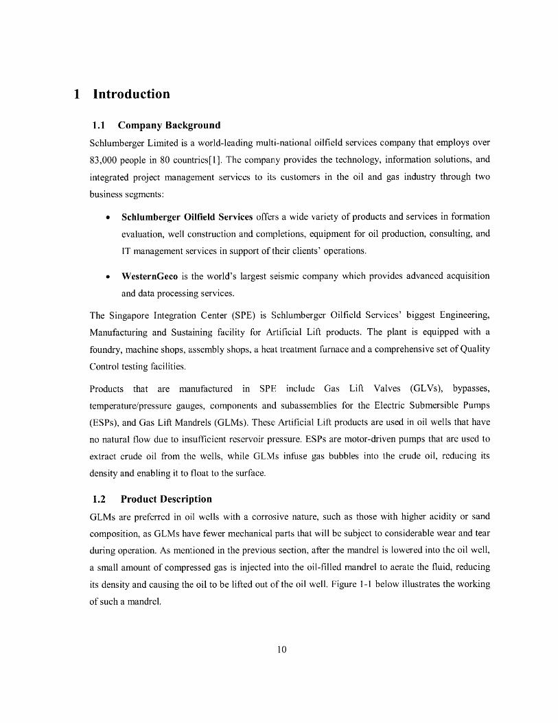
1.2 Product Description
GLMs are preferred in oil wells with a corrosive nature, such as those with higher acidity or sand
composition, as GLMs have fewer mechanical parts that will be subject to considerable wear and tear
during operation. As mentioned in the previous section, after the mandrel is lowered into the oil well,
a small amount of compressed gas is injected into the oil-filled mandrel to aerate the fluid, reducing
its density and causing the oil to be lifted out of the oil well. Figure 1-1 below illustrates the working
of such a mandrel.

Produced fluid
CasingAnnulus
Reservoir
Gas lift
Gas Lift Mandrel
Figure 1-1: A Gas Lift Mandrel (GLM) in operation[1]
GLMs are manufactured in different diameters, lengths, features, and materials, and can be
categorized into various product families accordingly. However, significant manufacturing
differences only occur between two groups of mandrels; mandrels that have round cross-sections, and
mandrels that have oval cross-sections. On average, the mandrels are approximately two metres in
length, and twenty centimeters in diameter.
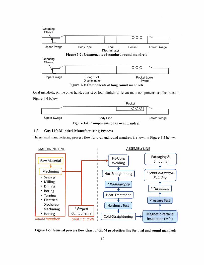
Round mandrels can be further broken down into two types; standard round mandrels and long round
mandrels. Standard round mandrels are made up of six components, while long round mandrels are
made up of four components. These components are shown in Figure 1-2 and Figure 1-3 for both
types of round mandrels respectively.
. ............... ...... . .............. . ..........
e9-1m ,-=infection naw
OrientingSleeve
000
Upper Swage Body Pipe Tool Pocket Lower SwageDiscriminator
Figure 1-2: Components of standard round mandrelsOrientingSleeve
0 0 0
Upper Swage Long Tool Pocket LowerDiscriminator Swage
Figure 1-3: Components of long round mandrels
Oval mandrels, on the other hand, consist of four slightly-different main components, as illustrated in
Figure 1-4 below.Pocket
000
Upper Swage Body Pipe Lower Swage
Figure 1-4: Components of an oval mandrel
1.3 Gas Lift Mandrel Manufacturing Process
The general manufacturing process flow for oval and round mandrels is shown in Figure 1-5 below.
MACHINING LINE I ASSEMBLY LINE
Figure 1-5: General process flow chart of GLM production line for oval and round mandrels
12
I -, I

The overall manufacturing process can be separated into the machining and assembly lines. As shown
in Figure 1-5 above, four components of the oval mandrels are forged by an outsourced supplier and
need not go through the in-house machining line. These forged components go directly into the
assembly line which starts with the Fit-Up process and ends with Packaging and Shipping. The four
or six components of round mandrels, on the other hand, are firstly machined in-house from raw bar-
stock purchased from an external supplier before proceeding downstream into the assembly line. All
assembly workstations that the round and oval mandrels flow through are shared. Both types of
mandrels have similar assembly processes and are treated equally.
There are four inspection processes in the assembly line that are highlighted in blue, namely
Radiography, Hardness Test, Magnetic Particle Inspection (MPI), and Pressure Test. Processes in
italic font are currently outsourced processes, namely Radiography, Threading, Sand-blasting, and
Painting.
GLMs are highly customized in nature; whenever a customer places an order, a team of designers will
discuss with the customer to understand his needs and to work out the mandrels' technical
specifications. Depending on the customer's requirements, the mandrels may have unique features, or
features with dimensions different from other mandrels. Thus, mandrel components of a particular
customer's order will have their own unique part numbers as component identifiers. Multiple parts,
each with a component part number, are then given a new serial number when they are assembled
together to identify the particular mandrel. Figure 1-6 below illustrates this. The manufacturing
process flow might differ slightly from time to time depending on specific customer requirements.
Currently there are about 50 different designs of oval mandrels and about 40 different designs of
round mandrels. Each time a new mandrel design with new features is released, new mandrel part
numbers are created. A more detailed description and analysis of the process flow will be covered in
Chapter 2.

Figure 1-6: A long round mandrel that is made up of four components
1.4 Current Manufacturing Issues
Significant growth in the sales of Gas Lift mandrels is expected in the coming years. In order to make
Schlumberger the one of the market leaders in Gas Lift systems worldwide, efforts to increase
manufacturing capacity to meet customer demand with competitive lead time, cost, and quality have
been put in place.
Table 1-1 below shows the projected number of mandrels that need to be produced per week over the
next few years.
Table 1-1: Projected number of mandrels to be produced per week
Oval mandrels Round mandrels Total mandrelsYear
per week per week per week
2009 13 3 16
2010 38 9 47
2011 60 25 85
2012 103 25 128
2013 120 26 146
The current manufacturing capacity is able to produce a maximum of 50 mandrels per week. Thus, it
is necessary to improve the throughput rate in order to meet the projected demand over the next few
years. Capacity expansion projects might become a need should the above trend in future demand
materialize.

Also, current manufacturing lead times are much longer than total processing times due to excessive
Work-In-Process (WIP). This results in high non-value-adding (waiting) times. We note that
achieving less WIP will reduce waiting times and consequently reduce the manufacturing lead times.
Shorter manufacturing lead times will in turn enable a quicker response to customer orders, ensuring
better customer service and on-time delivery.
The above issues have various contributing factors. One of them is the unbalanced manpower
distribution among workstations in the assembly line, which will be discussed in more detail in
Chapter 2. Engineers and managers in the department are aware of this problem and have been trying
to find a solution to it. This project seeks to address this problem, and further discussion will follow
in the other sections of this thesis.

2 Problem Statement
2.1 Introduction
The focus of this project is to address manpower management issues in the GLM assembly line to
meet the expected increase in customer demand over the next three years. This chapter describes the
problem to be addressed in greater detail by characterizing the GLM assembly line.
2.2 The Process Flow
As introduced in Section 1.3, the components for both round and oval mandrels arrive at the first
station of the assembly line as separate pieces upon the release of a Work Order by the Production
Planner. A Work Order of round mandrels typically consists of a batch of four mandrels, while that of
oval mandrels contains four to six mandrels. Work Orders are sized this way so that one Work Order
of mandrels can fit into the heat treatment furnace as a batch. Oval mandrels are generally smaller
than their round counterparts, thus their Work Orders can be slightly larger.
Both round and oval mandrels go through similar assembly processes, sharing many other resources
along the line. This can be seen in Figure 2-1 and Figure 2-2. After the components are tack welded
together at their respective fit up stations, they go through the same assembly and inspection stations
in the shop floor. However, due to differences in material, size and features of the two types of
mandrels, there are several differences in the assembly process:
1. Processing times of round mandrels may be longer or shorter than oval mandrels. For example, as
round mandrels do not go through plasma cutting and welding of pockets, they warp less and thus
pass through the Hot Straightening station faster. However, at round mandrels tend to stay longer
in the OD grinding machine as they are bigger and made of harder materials.
2. Round and oval mandrels have different Non-Destructive Examination (NDE) standards,
imposing different requirements on them. Some materials or types of mandrels may require only
partial sampling to be performed at the inspection processes, while some may need 100%
inspection.
3. Some round mandrels have special features which require additional processing, such as guard
rails or keeper plates. Oval mandrels do not enter any of these additional processes.

Figure 2-1: Process flow of oval mandrels[21 &ODDffing
11. MPI
Figure 2-2: Process flow of round mandrels
2.3 Characterization of the Assembly Line
A tour of the assembly line will reveal that all processes are very labor-dependent, except for the
robotic plasma cutter and heat treatment furnace, both of which only require a worker for loading and
unloading mandrels. All other processes require at least one worker to be present for each mandrel in
process. For example, at a full welding booth, the welder will push a tack-welded mandrel into the
booth, grind off the tack-welds and perform a full welding procedure manually. A characteristic of
such a labor-intensive process is that the processing time will be highly variable. A refreshed and alert
worker will be able to weld faster than one who is physically ill or exhausted. In addition, an
.......... . ..... .......

experienced welder will be able to work faster than a newly trained welder. This makes it difficult to
determine a single, representative processing time for each of the processes.
As welding is the only procedure used to join the components together to form a mandrel, the quality
of welds is critical to the overall functionality of the mandrel. Porosities in the weld may cause
leakages to occur when the mandrel is in operation. In extreme but possible scenarios, the mandrels
may explode at the welds when subject to high pressures. This is the reason why quality inspections
in the assembly line are so important, especially the pressure test bay which is termed as a
functionality test. Figure 2-3 shows the First Pass Yield percentage of mandrels that are tested in each
of the inspection stations, from January 2009 to April 2010.
120%
100% -
80% -4-Round Machining Inspection
-4- MPI
-- r- Radiography (Round mandrels)
60% -- Radiography (Oval mandrels)
-W- Hardness Test
-- Pressure Test
40% -+ ID Drift
--- Assy RTY %
20% -- 4
0%
J09 F09 M09 A09 M09 J09 J09 A09 S09 009 N09 D09 J10 F10 M10 A10
Figure 2-3: First Pass Yield percentage of mandrels at each inspection station[31
The top seven lines show the first pass yield at the inspection stations as shown previously in the
process flow charts (Figure 2-1 and Figure 2-2), while the last line, Assy RTY%, is the product of the
above lines. The Assy RTY% can be seen to be improving over time, which is consistent with our
intuition of a labor-intensive industry - the workers gain skills and experience over time, thus the
quality of their work improves over time as well.
. ... .......
Another characteristic of the assembly line is that some processes require the operator to undergo a
specialized course and obtain a certification before he is allowed to work. These processes are,
namely, the full welding booths, heat treatment furnace, and the Magnetic Particle Inspection station.
Certified workers are required at the heat treatment furnace as they have to configure the process
parameters (temperature increases, duration of treatment) and monitor the status of the furnace once
in a while to ensure that the process is going on smoothly. Moreover, as the workers have to get very
near to the red-hot mandrels and furnace, they have to undergo special training to ensure their safety.
Workers in all other processes do not require specialized certifications and are thus allowed to help
out across different processes.
There are two consequences to this requirement. Firstly, workers will have to be employed early
enough to allow for training. This is particularly true since the quality of their work will only increase
to acceptable standards after a few months in the shop floor. Secondly, since only certified workers
are allowed at certain processes, other workers cannot replace their positions; they can only help out
as assistants.
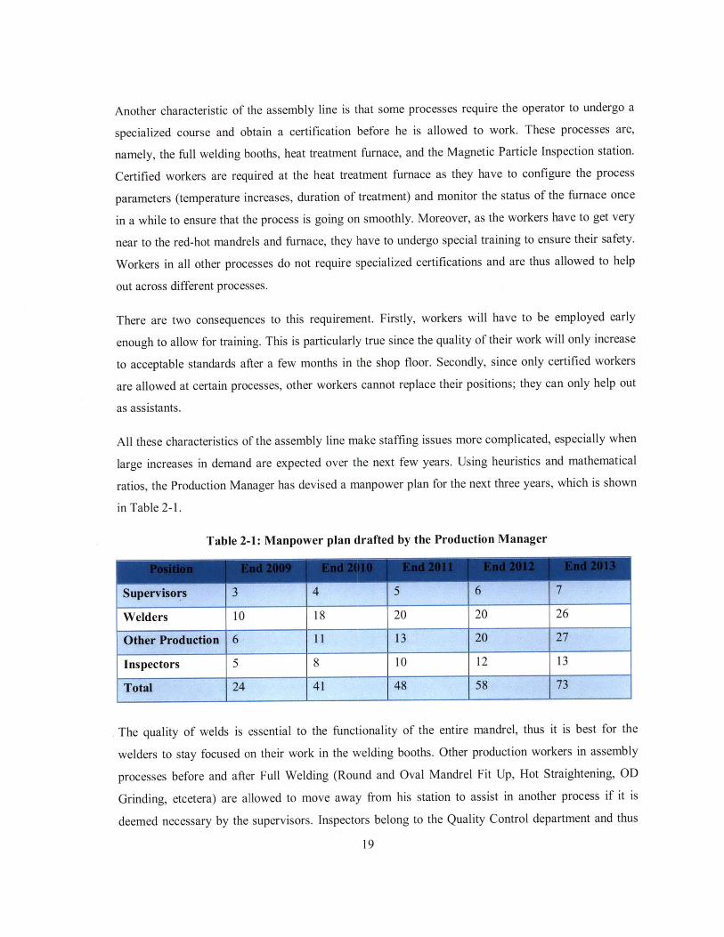
All these characteristics of the assembly line make staffing issues more complicated, especially when
large increases in demand are expected over the next few years. Using heuristics and mathematical
ratios, the Production Manager has devised a manpower plan for the next three years, which is shown
in Table 2-1.
Table 2-1: Manpower plan drafted by the Production Manager
Supervisors 3 4 5 6 7
Welders 10 18 20 20 26
Other Production 6 11 13 20 27
Inspectors 5 8 10 12 13
Total 24 41 48 58 73
The quality of welds is essential to the functionality of the entire mandrel, thus it is best for the
welders to stay focused on their work in the welding booths. Other production workers in assembly
processes before and after Full Welding (Round and Oval Mandrel Fit Up, Hot Straightening, OD
Grinding, etcetera) are allowed to move away from his station to assist in another process if it is
deemed necessary by the supervisors. Inspectors belong to the Quality Control department and thus
19
....................

are not included in the "Other Production" workers' headcount. In the assembly line, they are in
charge of Hardness Test, Magnetic Particle Inspection and Pressure Test.
If we were to consider workforce flexibility and the fact that the facility runs on three shifts a day, the
manpower allocation and planning problem actually becomes even more complicated. Complexity is
further increased if we double the number of workers to 96 workers at the end of 2013, as suggested
by Table 2-1. Therefore, there is a need to devise a more systematic method in deciding the
employment, training and deployment of workers on the shop floor.
2.4 Objectives and Scope
The primary objective of this project is to reduce the cycle time of processes to meet the planned
cycle times for the next few years. Cycle time is defined as the average duration taken by a process to
complete operations on one mandrel. For a process that works on only one mandrel at a time, the
cycle time is simply the difference between the start and end times of that station. For a batch process
such as Heat Treatment, that difference in time is divided by the number of mandrels in the batch.
As dictated by the company, the planned cycle time of a particular year is 85% of the year's takt time.
Takt time is the amount of time needed to produce a part in order to satisfy the rate of demand.
Specifically, for the given demand forecasts, the planned cycle times for a three shift assembly line
are as follows: 113min by this year, 58min in 2011, 43min in 2012 and 38min in 2013.
In support of the primary objective, the second objective would be to develop a model which will
assist the Production Manager in manpower employment and deployment decisions. This model
should aim to maximize the flexibility of the assembly line, yet incur minimal additions in cost of
labor. It should also be a revisable model that can be changed over time, as continuous improvements
are to be expected in all manufacturing lines and as the company updates its demand forecasts.
However, due to time constraint and the complexity of the entire production line, only in-house
assembly processes from the fit-up booths to the pressure test bay will be considered. We do not
consider machining processes prior to the assembly line and outsourced processes such as
Radiography, Sand Blasting, Painting and Threading, as these are deemed out of scope for this project.

3 Literature Review
3.1 Takt time
Takt time is the amount of time that a factory is allowed to produce a unit of the product in order to
meet the rate of customer demand[4].
Takt time = Available working time per dayCustomer demand per day
This is a target time used to synchronize the rate of production with the rate of sales, so that over or
under-production do not occur. To prevent Work-In-Process (WIP) from building up or from stocking
out between processes in the production line and causing blockages/starvation to occur, all processes
should be balanced such that they produce to the takt time.
3.2 Workforce Flexibility
This concept involves cross-training workers across different processes, so that they can be shifted
from one process to another. Workforce flexibility can be implemented when the processes involved
are labor-intensive in nature, and if bottlenecks are present in the system. Workforce flexibility allows
the workers in faster processes to help out in the slower processes, achieving some form of line-
balancing. In [5], Molleman and Slomp designed linear programming models and developed a
hierarchical procedure for cross-training to ease the workload of the bottleneck worker.
Also, as workers are able to switch tasks rapidly, the production line will be able to respond quickly
to changing demand[6]. This results in less Work-In-Process (WIP) and higher response times.
However, in [7] Slomp and Molleman has shown that there is a limit to how much cross-training
should be done on the workers. Diminishing returns are observed after workers are cross-trained on
several tasks. As a result, it is important to determine the optimum number of tasks that workers are
cross-trained on, so as to reap the maximum benefits of cross-training.
3.3 Job Rotation Scheduling
Job rotation scheduling is closely related to cross-training, since workers have to be cross-trained
before they can be rotated over several jobs. One of the main rationales behind job rotation is to
minimize occupational injuries, particularly in highly repetitive work environments [8]. The situation
is aggravated in workplaces where frequent manual material handling is expected. In these
workplaces, back injuries are a leading cause of lost workdays[9].

Other than reducing the possibility of occupational injuries, job rotation also helps in reducing
dullness from doing the same job repeatedly, thus increasing productivity and job satisfaction. It also
aids in improving alertness and reduces errors[I 0].
3.4 Mathematical modeling for workforce flexibility
Due to the complexity of workforce flexibility, many recent researchers have focused on using linear
programming or mixed integer linear programming to compute optimal or near-optimal solutions.
These solutions are then used as decision-aids to the managers in planning how to cross-train workers.
Stewart[ 11] formulated four models separately to minimize the total cost of training, maximize the
flexibility of the workforce, minimize the total training time and optimize the trade-off between cost
of training and the amount of flexibility achieved. To put the problem into a realistic manufacturing
context, the paper also included constraints such as the amount of available production hours,
production requirements and budget given.
Hertz, Lahrichi and Widmer[12] devised a mixed integer linear programming (MILP) model which
balances the workload of workers across different multiple shifts without any shortages in capacity.
They found that annualizing working hours is not just economically beneficial, but also allows the
company to plan productive capacity to meet changes in demand, achieving flexibility. Different
employment strategies such as gradual hiring and part time work were also studied with the MILP
model.

4 Methodology
This chapter describes in detail the procedure used to obtain the manpower plans for the years 2011 to
2013. Data were first gathered from time study at all processes in the shop floor, as well as interviews
with the production manager, supervisor and shop floor workers. The time study also revealed that the
workers were not productive all the time, which is a crucial aspect to consider and will be discussed in
Section 4.2. The Planned Cycle Times of each process were then calculated with the demand forecasts
and compared with the manual work content obtained from the time study to formulate the manpower
employment and deployment plans.
4.1 Data Collection and Analysis
The first stage of analysis entails collecting relevant data from the shop floor to further characterize
the actual process flow. This also provides a benchmark for comparison of results after solutions have
been developed.
A one-month long time study was conducted at all assembly and inspection processes to document
the list of operations for each process. The start and end times of each operation were also recorded
dutifully with a digital watch. If a worker was seen to stray away from the process, such as to help out
in another process or simply to take a break, the time would be stopped and restarted only when the
worker resumed the operation. All observations were made in the first shift, as the author was not
allowed to enter the shop floor in the second and third shift as an intern.
As all processes were operational in the first shift, the author was able to observe multiple processes
simultaneously. By standing between processes that were in close proximity to each other, the author
could observe and time as many as three processes at a time. However, some processes were
conducted in enclosed rooms, such as the Full Welding and Pressure Test. Observations of these
processes were performed individually.
Although the company has two systems (one manual and the other computerized) to record
processing times, the timings only capture the overall cycle time for each process and not the detailed
tasks at each station. Moreover, some of these data may not accurately reflect the actual cycle times,
as they are not always recorded faithfully at the start and end of each process.
Short interviews were also held with the workers to understand the importance of each task they
carried out. This is important, as the workers are the most experienced and knowledgeable of their
areas of focus. As each process involves different operations with different equipment, general
23

questions were first put forward to the workers. These include how the process was carried out and
what difficulties they faced. Other process-specific questions were then developed along the way as
the workers divulged more about their work.
The workers might have deviated from the Standard Operating Procedures (SOPs) by improving the
process on their own over time, or they may have grown accustomed to certain imperfections in the
process. It will be critical at this point to single out these imperfections before further analysis is
performed.
The individual tasks in each process were then categorized into Specialized or General Tasks.
Specialized Tasks are those that have to be completed by a worker who is fixed at that station, while
General Tasks can be done by general helpers, who are available to help out in other processes as well.
Appendix II shows how the tasks in all processes are separated into Specialized and General Tasks,
while Section 5.6 describes how this arrangement is incorporated in the manpower plans to reduce
cycle times.
4.2 Proportion of productive working hours
An important factor to consider when deciding the number of workers to employ would be the actual
working hours of an average worker. The takt time equation in Section 3.1 assumes that the
production line is working at 100% efficiency throughout the available working hours. However, in a
labor-intensive assembly line, it would be impractical to assume that the workers would work at a
constant rate throughout their shift.
Other than the official breaks that are given to the workers (a 30-minute lunch break at 12 noon and
two 15-minute tea breaks at 9:30am and 2:30am respectively for those in the first shift), it is normal
for the workers to take occasional toilet breaks, or to stop their work to engage in short conversations
with their colleagues. The proportion of time spent on these unofficial breaks may vary across
different companies and different cultures.
To obtain an estimated percentage of the productive working hours in the GLM assembly line, several
workers were chosen at random as subjects of observation. The time at the start of the observation
was recorded and paused when the workers stop for any unofficial breaks. The timing was then
restarted when work was resumed, and the time at the end of the observation was also noted. The
following equation was then used to calculate the percentage of productive working hours of an
average worker:

Proportion of productive working hours = te-ts (3)n
where w = work content, t, = time at the start of the observation, te = time at the end of the
observation and n = number of observations.
A person's behavior is often affected when he is being observed by someone, particularly a stranger.
Thus, before the time study was carried out, the author had spent a month visiting the shop floor to
build rapport with the workers and to conduct the short interviews in a casual setting. This helped the
workers to familiarize themselves with the author and reduced any psychological uneasiness during
the actual time study. Moreover, during the time study, the author often observed multiple processes
at once and was thus a distance away from the workers. By maintaining a physical distance away
from them, the workers should have been able to behave as they normally would, resulting in
sufficiently representative results in the calculation of the proportion of productive working hours.
4.3 Planned Cycle Time
The concept of takt time was introduced in Section 3.1 as a target time to produce a part in order to
match the rate of customer demand. However, to obtain a more realistic and accurate gauge of how
fast each process should be in the assembly line, two corrective factors have to be used in
conjunction with Equation 1 to attain the Planned Cycle Time for each process.
Planned Cycle Time = Available working time per day x Inef iciency Factor x Proportion of productive hours (4)Cuatomer demand per day
The Inefficiency Factor is a ratio utilized by the company to account for equipment downtimes,
rework and variations in processing times between mandrels. As mentioned in Section 2.4, this ratio
was dictated by the management to be 0.85.
4.4 Formulation of manpower plans
Several assumptions were made during the formulation of manpower plans. Firstly, we assume that
all forecasts on future demand are accurate. All calculations on takt times and Planned Cycle Times
were based on these forecasts. We also assume that no major changes are made to processes within
the next few years, which will revolutionize the manual work contents and thus result in a change in
need for manpower.
From the time study mentioned in Section 4.1, the manual work content of each process was
calculated. This time is compared to the Planned Cycle Time for a shift. If the manual work content
exceeds the Planned Cycle Time, it means that the process is too slow to fulfill the rate of demand. A25

second shift will be added to this process to reduce the Planned Cycle Time by half. This continues
till all three shifts have been allocated to the process. When this happens, another worker will have to
be added to a shift to reduce the Planned Cycle Time even further.
This framework ensured that the primary objective of achieving the planned cycle time was met, and
that a solution with minimal number of workers was generated, sufficient to meet the expected
demand over the next few years.
In order to improve the utilization rate of workers, workforce flexibility was incorporated into the
manpower plan by grouping the processes into clusters and allowing the workers within a cluster to
move across different processes in the cluster.
General Tasks in the clusters were then combined to see if there is sufficient work to be allocated to a
full-time General Worker. If not, these tasks will remain in the process to be performed by the worker
assigned to the particular process.

5 Results and DiscussionThis chapter presents and discusses the results that are derived from data in Appendix I and II.
5.1 Proportion of productive working hours
We found that for a normal shift of eight hours with an hour of official breaks (lunch and tea breaks),
the workers spent another 1.23 hours on unofficial breaks on average. The remaining 5.77 hours are
spent on working in their own stations. Figure 5-1 shows a breakdown of the timings.
Official breaks13%
Unofficialbreaks
15%
Figure 5-1: Breakdown of working hours for a normal shift
The proportion of time spent on working can be imagined as the "uptime" of the workers, when they
are actually performing value-adding activities to the mandrels in their station. It may seem tempting
to try and reduce the amount of unofficial breaks by asking the workers to refrain from unnecessary
conversations and toil without respite. However, this is impractical and inhumane, since the workers
cannot and should not be seen as machines. The harsh and dangerous working environment in the
assembly line makes it necessary for workers to take a rest once in a while to prevent work fatigue
and injuries.
This particular analysis will help in understanding how efficient the workers are, and how many more
workers we should employ to cope with the expected increase in demand in the near future.
5.2 Planned cycle time analysis
Figure 5-2 shows the demand forecast of oval and round mandrels from Year 2010 to 2013. Demand
for both round and oval mandrels is expected to increase by 205% and 170% respectively by the year
2013, exerting strain on the current manufacturing capacity.
... .......... .......

Figure 5-2: Demand forecast of GLMs
With the Equation 1 shown in Section 3.1, the takt times of three-shift, two-shift and single-shift
processes can be calculated for each year till 2013, with the assumption that the assembly line
operates 5.5 days a week. This will be further explained in Section 5.4. The takt times are illustrated
in Figure 5-3, Figure 5-4 and Figure 5-5 respectively. It can be seen that as demand increases across
the years, the takt time has to decrease so as to produce mandrels sufficiently fast to satisfy customer
orders.
Figure 5-3: Takt times for 3-shift processes
150.0 128.5
100.0W 64.3
.E 53.6 45.950.0
0.0
2010 2011 2012 2013
Year
..........
.... .... .. .. ....... .. ......

100.0 85.7
- 80.0
T 60.0E * 35.7i- 40.0
M 20.0
0.0
2010 2011 2012 2013
Year
Figure 5-4: Takt times for 2-shift processes
50.0 42.8
- 40.0
T 30.0E 17.9j- 20.0
M 10.0I-
0.0
2010 2011 2012 2013
Year
Figure 5-5: Takt times for 1-shift processes
Equation 4 was then used to calculate the Planned Cycle Time for each process. The Inefficiency Factor
was given a value of 0.85 by the management. The proportion of productive hours is a ratio explained in
the previous section, and is given a value of 0.72. The Planned Cycle Times for each process is tabulated
in Table 5-1.

Table 5-1: Planned Cycle Times (in minutes) from 2010 to 2013
Planned Cydle Times (min)
22012 10 201.C 67.3 33.3 112.5 15.0 37.5 124.9 16C 41.3 146.8 95.9 49.9
2011 1 20.0 33.7 16.3 56.2 37.5 18.0 62.9 41.3 20. 73.8 49.9 97.9
2012 500C 40.4 26.9 13.5 45.0 30.0 15.0 49.6 33.1 16.5 58.8 39.2 19.6
2013 6000 33.7 22.4 11.2 37.5 25.0 12.5 41.3 27.5 13. 49.0 32.6 16.3
2010 S00 40C 1 269.4 134.7 450.C1 300.0 150.( 495.8, 330.6 165.3 587.(, 391.7 195.9
2011 100C 202.0 134.7 67.3 225.C 150.0 75.( 247.9 5 . 82.6 293.81 9. 97.9
2012 100[ 202.0 134.7 67.3 225.C 150.( 75.( 247.9 165.3 2 . 293.81 99 97.9
2013 1000 202.( 134.7 67.3 225.C 150.( 75.( 247.9 165.3 82.6 293J8 19, 97.9
2010 250C 80.8 53.9 26.! 0. 60.( 30.( 99.2 661 33.1 117.! 78.3 39.2
01L'001LL2011 500[ 40.41 26.9 13.! 45.C, 30.0 15.( 49.6 33.1 16.5 58J8 39.2 19.6
2012 600 33.7 22.4 11.: 37.5 25.( 12.! 41.32 7. 13.8 49.( 2. 16.3
2013 7000 28.9 19.2 9.6 32.1 21.4 10.7 35.4 23.6 11.8 42.0 28.0 14.0
The Planned Cycle Times for Oval, Round and Total (both types of mandrels) are shown, as some
processes were dedicated to one type of mandrel, while the other processes were shared between
both the oval and round mandrels.
Specifically, the following processes were dedicated to oval mandrels:
1. Oval Mandrels Fit Up
2. Plasma Cutting
3. Pocket Fitting
The following processes were dedicated to round mandrels:
1. ID Welding
2. Round Mandrels Fit Up
The other processes are shared between both oval and round mandrels:
1. Full Welding
2. Hot Straightening
3. OD Grinding
4. MPI
5. Heat Treatment
6. Hardness Test
7. Cold Straightening
8. OD Drift
9. Pressure Test

We see from Table 5-1 that the Planned Cycle Time depends on the projected demand for a
particular year, the number of working days per week and the number of shifts per day. As projected
demand increases over the years, the Planned Cycle Time decreases as the assembly line will have to
produce mandrels at a faster rate to meet up with the rate of demand. On the other hand, increases in
number of working days per week or number of shifts per day will both augment the available
working hours, allowing the assembly line to produce at a slower (and more reasonable) rate.
Although there are normally five working days a week, the number can be increased by asking the
workers to work overtime before or after their normal shifts, or asking them to return on weekends to
work. This strategy is possible but not advisable, and will be discussed further in Section 5.4.
5.3 Average manual work content of each process
A series of tasks are performed on each mandrel as they arrive at each process, such as loading,
grinding, calibrating, welding, et cetera. As mentioned previously, most of these tasks are performed
by workers; very few are automated. Even these few automated tasks, such as those in the plasma
cutting and pressure testing processes, have to be closely monitored by the workers. Appendix II
shows the list of tasks that are executed at each process and the average task times taken by different
mandrels. The average manual work content per mandrel of each process is illustrated in Figure 5-6.
450.0 125.8
400.0
e 350.0
0 300.0U- 250.003 200.0
S150.0 106.92 100.0 59. 320 - 4139
40.1 34 4 48.0
0.0. -- I A As -A --A
A. ~. 1
Figure 5-6: Average manual work content per mandrel of processes
The average manual work content at MPI has been multiplied by 0.3, since only 30% of the mandrels
were required to go through MPI. Out of all the processes, only Heat Treatment was a batch process
where multiple mandrels were secured to a basket before being lowered into the furnace. During the
entire heat treat cycle, the basket was transported several times from one furnace to another, or to a
polymer/air cooling tank. All these manually operated transportations took 196 minutes in a cycle,

Ii'
and this time is divided by six, which was the average number of mandrels that were carried in the
basket per cycle.
It is evident that the Full Welding process requires the most manual work per mandrel. This is due to
the fact that welding is a slow, serial process that acts on a small spot relative to the total area of the
mandrel.
Area of action<<Total Area : Serial Process Area of action-Total area : Parallel Process
Figure 5-7: Serial and parallel processes [13]
Moreover, the following factors make welding of mandrels a slow process which is difficult to
automate:
1. Components of mandrels are sometimes made of materials with different heat codes
2. Welding gaps between components often have inconsistent widths
3. Challenging geometry of the mandrels
4. Uneven weld surfaces and the presence of tack welds, which require substantial grinding
throughout the welding process
As a result, increasing the number of welders might be the only simple way to reduce the cycle time
of the welding process substantially.
Although the other processes have significantly smaller manual work contents as compared to Full
Welding, most of them are still too large to meet the projected demand with the current
manufacturing capacity. Capacity thus has to be enhanced by increasing the number of shifts and/or
the number of workers per shift. This will be elaborated further in the Section 5.6.
5.4 Baseline analysis
To determine if the model of work content accurately reflects the actual operations of the shop floor,
we used it to calculate a theoretical number of workers required in order to achieve the actual
throughput of mandrels in the previous month. The calculations were done in an Excel spreadsheet,
shown in Appendix II.

Table 5-2: Summary of current manpower status
2 Other Production ID Welding 17 12
Round Mandrel Fit Up
Oval Mandrel Fit Up
Plasma Cutting
Pocket Fitting
Hot Straightening
OD Grinding
Heat Treatment
Cold Straightening
OD Drift
3 Inspection Hardness Test 3 2
Magnetic Particle Inspection
Pressure Test
Total 28 26
Table 5-2 compares the theoretical number of workers required with the actual number of workers
that are deployed on the shop floor. The numbers appear to coincide fairly well, suggesting that the
model is sufficiently accurate and realistic for drafting manpower plans for the following years.
However, twelve welders were predicted with the model, which is 50% more than the actual number
of welders currently employed. This explains why the welders have been working overtime for at
least the past month. The production supervisor has commented that the Full Welding process was
understaffed, thus the welders have to work overtime to meet up with the demand.
We noticed during the time study that all the workers have been working overtime for at least a
month. They worked for an extra two hours on several weekdays, and everyone had to return for a
full day on Saturday. Thus, when calculations were done for the theoretical number of workers in
Table 5-2, it was assumed that the workers worked six to seven days a week.
This situation may not be sustainable for the long term, as hints of fatigue and lethargy could already
be seen on some of the workers. The incoming increase in demand will directly translate into a larger
workload for the workers, aggravating the situation further. We therefore decided that manpower
......... . INNNN 9W FIV4111POWN- e-00-ww'- Aimmommiew iiwwmwww 919. , - MOMMM000! 180900" &NAN'. -

plans of future years should be calculated with the assumption that workers work five to five and a
half days a week. The extra half day is included in the calculations as the management would like to
maximize the utilization rate of workers. If only five working days are considered in the manpower
plans, workers might become idle during periods of low demand. The management deems the idling
of workers as waste, which should be avoided.
Another observation made during the time study was that several processes required significant
grinding of mandrels as the initial preparatory steps of the processes. Other than taking up the
worker's time, it also caused the mandrel to occupy the workstation for a period of time longer than
necessary. This can be seen in Appendix I, the work content of all processes in the assembly line. If
the grinding operations can be performed by another worker before the mandrels enter the individual
processes, the cycle time will be effectively reduced. This will be discussed in further details in
Section 5.6.
5.5 Employment and deployment of workers
To determine exactly how many workers should be employed over the next few years and how they
should be trained and deployed in the shop floor, all assembly processes in the shop floor are grouped
into clusters of two to three processes, according to their sequence in the process flow and their
location in the shop floor. Table 5-3 shows how the clusters are configured.
Table 5-3: Proposed clusters and their constituent processes
Oval Mandrel Connection Oval Mandrel Fit UpPlasma CuttingPocket Fitting
3 Full Welding Full Welding4 Pre-Heat Treatment Hot Straightening
OD Grinding5 Post-Heat Treatment Heat Treatment
Cold StraighteningOD Drift
6 Inspection Hardness TestMagnetic Particle InspectionPressure Test
There are several advantages to cluster processes in this manner. As mentioned in Section 3.2,
diminishing returns result as the level of cross-training exceed a certain number of tasks, as workers34

tend to lose focus in their work. By grouping just two or three related processes in a cluster, the
workers will be able to concentrate better and yet allow for some degree of workforce flexibility
within the cluster. Job rotation, which was discussed in Section 3.3, can also be implemented in the
cluster to mitigate the risk of occupational injuries and improve alertness.
Practicing workforce flexibility within the small clusters will also help to improve the utilization rate
of workers. Table 5-4 shows the difference in worker utilization rates before and after implementing
workforce flexibility in the Oval Mandrel Connection cluster in the year 2012. It can be seen that one
less worker will be required in the cluster if workforce flexibility is practiced, improving the
utilization rate from 0.82 to 0.94.
Table 5-4: Utilization rates of Oval Mandrel Connection cluster with and without workforceflavihilifv
No. of workers required 8
Available productive time (min) 2353 2059
Utilization rate 0.82 0.94
Moreover, as the number of workers in the assembly line is expected to increase considerably over
the years, problems may arise when it comes to manpower control and communication. When such a
scenario arises, team leaders can be appointed in each of these clusters to aid in communicating
instructions and quality concerns from the management to the other workers. Conversely, feedback
can be collected from the workers and conveyed back to the management through these team leaders.
..- ....... ........ ........ . ....... ... .................. .............. .

5.6 Manpower plan for 2011
Table 5-5 illustrates the number of workers that should be deployed to each cluster, in order to
achieve the Planned Cycle Times. A total of 56 workers will be required in the assembly line.
Table 5-5: Manpower plan for 2011
1 Round ID Welding
Mandrel Round Mandrel Fit Up
Connection
3 Full Welding Full Welding
5 Post-Heat Heat Treatment 3 3 3
Treatment Cold Straightening
OD Drift
Total 56
The number of workers has been evenly distributed across three shifts, in order to minimize the
number of workstations required at each of the processes. This is an important consideration as the
shop floor has a limited area for expansion. It would be infeasible to allocate all the workers to one
shift as it would lead to a waste of space, idleness during the other two shifts and higher WIP. For
example, in the Pre-Heat Treatment cluster, if all seven workers are allocated to the first shift, there
must be seven workstations for them to work on. On the second and third shifts, these workstations
will be totally unoccupied and idle. At the same time, if the upstream clusters are still working
around the clock, WIP will pile up at this cluster during the second and third shifts. It is thus
beneficial to have an equal and consistent number of workers across all three shifts in each cluster.
, ,, ' I" - - - - - - - 0 - ................ .......................

It was discussed in Section 5.4 that significant grinding was required prior to several processes.
These have been classified as General Tasks that can be taken out of the process and managed by a
separate worker. In this manpower plan, a total of 3 grinders will be required, and their job-scope is
listed in Table 5-6.
Table 5-6: Job scopes of grinders in 2011
There are several advantages to having these grinders in the shop floor:
1. Allow the workers at the processes to focus better on the main operations.
2. Reduce the cycle time of processes.
3. Savings in cost of labor, as grinding requires little or no training. Grinders can be paid a
lower salary relative to other skilled workers.
It can be seen in Table 5-7 that the worker utilization rate of each cluster is relatively high,
ranging from 0.77 to 0.99.
Table 5-7: Utilization rates of clusters in 2011
.... .... .. ...... ..

5.7 Manpower plan for 2012
Table 5-8 illustrates the number of workers that should be deployed to each cluster, in order to
achieve the Planned Cycle Times in the year 2012. A total of 75 workers will be required in the
assembly line.
Table 5-8: Manpower plan for 2012
1 Round ID Welding 2
Mandrel Round Mandrel Fit Up
Connection
3 Full Welding Full Welding /I I 14
Similarly, Table 5-9 shows how many grinders should be employed and their respective job-scopes.

Table 5-9: Job scopes of grinders in 2012
It can be seen in Table 5-10 that the worker utilization rate of each cluster is relatively high, ranging
from 0.78 to 1.0.
Table 5-10: Utilization rates of clusters in 2012
5.8 Manpower plan for 2013
Table 5-11 illustrates the number of workers that should be deployed to each cluster, in order to
achieve the Planned Cycle Times. A total of 82 workers will be required in the assembly line.
. ... . .. .......... .. .........I . .......... ...............

Table 5-11: Manpower plan for 2013
Round ID Welding 2
Mandrel Round Mandrel Fit Up
Connection
Table 5-12: Job scopes of grinders in 2013

Table 5-13: Utilization rates of clusters in 2013
5.9 Evaluation of proposed manpower plans
As discussed, forming clusters of processes allows the workers to focus better, but still allows for the
implementation of job rotation and workforce flexibility. These two manpower scheduling concepts
can help to reduce the risk of occupational injuries and improve the utilization rate of workers,
respectively. In addition, appointing team leaders in each cluster will aid in communication and
manpower control as the number of shop floor workers increases multifold.
The introduction of grinders as low-skilled workers is a strategy to reduce the cost of labor and the
cycle time of processes, enabling the entire assembly line to achieve the takt time ultimately.
Currently, a regular workweek consists of 5 working days. Any extra working hours or days are
regarded as overtime. The manpower plans proposed in this thesis assume that there are five regular
working days a week and just half a day of overtime in order to reduce the amount of potential
overtime hours required. This brings about several advantages.
1. Most evidently, reducing the number of overtime hours results in a lower overtime labor cost.
Workers are paid 50% more than their usual rates when they work overtime, but they do not
work 50% faster during those extra hours. Overtime can therefore be seen as a form of waste and
should be reduced.
2. In the harsh environment of the assembly line, fatigue sets in easily on the workers. Elongating
the working hours with overtime will only aggravate the fatigue further, resulting in a further
decrease in productivity. This is supported by an observation made during the time study.
Towards the end of the shift, especially during the overtime hours, the workers took breaks
longer than stipulated, and stopped more frequently for conversations with each other. This
further verifies the point that overtime is wasteful and should be minimized.
3. Overtime should only be viewed as an additional overrun of capacity, which should only be used
to satisfy periods of high demand. By planning for only five and a half working days a week,
......................................... ................ .. .. ...... ..

there will be sufficient buffer for the assembly line to utilize the remaining time as overtime to
cope with any short term increases in demand.
As the calculations were derived from time study data collected by the author, and corrective ratios
were utilized in the calculations, the results should reflect the actual operations and requirements of
the assembly line. Since these results were computed from the projected demand of mandrels, the
manpower plans should provide sufficient workforce capacity should the demand forecasts
materialize.
However, this also means that the soundness of the manpower plans depends on the accuracy of the
demand forecasts. If the actual demand is lower than expected, we may be left with a large number
of workers, which may pose a huge liability to the company. It is therefore critical to revise the
manpower plans when updated and more accurate demand forecasts are obtained for the future years.

6 RecommendationsThis section summarizes the respective manpower plans till the year 2013, as presented and discussed in
the previous chapter. Several potential areas of improvement were also identified and the respective
recommendations will be proposed in this chapter to reduce the work content of processes. If successful,
these improvements will translate to a reduction in the calculated manpower plans.
6.1 Summary of Manpower Plan
Table 6-1 shows the number of workers that should be employed and deployed in each of the six
proposed clusters in the assembly line. For more details on how the workers are allocated into the
three shifts, please refer to Sections 5.6 to 5.8.
Table 6-1: Summary of manpower plans from 2011 to 2013
No Clse aePoese apwrfrYa
1 Round Mandrel ID Welding 7 3 4 4
Connection Round Mandrel Fit Up
2 Oval Mandrel Oval Mandrel Fit Up 5 7 8
Connection Plasma Cutting (2 are (2 are (2
Pocket Fitting grinders) grinders) gi
3 Full Welding Full Welding 8 27 36 4
4 Pre-Heat Hot Straightening 10 7 10 1:
Treatment OD Grinding (1 is a (2 are (3
grinder) grinders) gi
5 Post-Heat Heat Treatment 9 12 1
Treatment Cold Straightening
OD Drift
6 Inspection Hardness Test 3 5 6 6
Magnetic Particle Inspection (I is a (1
Pressure Test grinder) g
Total 28 56 75 81
............................... I ............................... ...................................................... I ................................................................................... .............. -
0
3
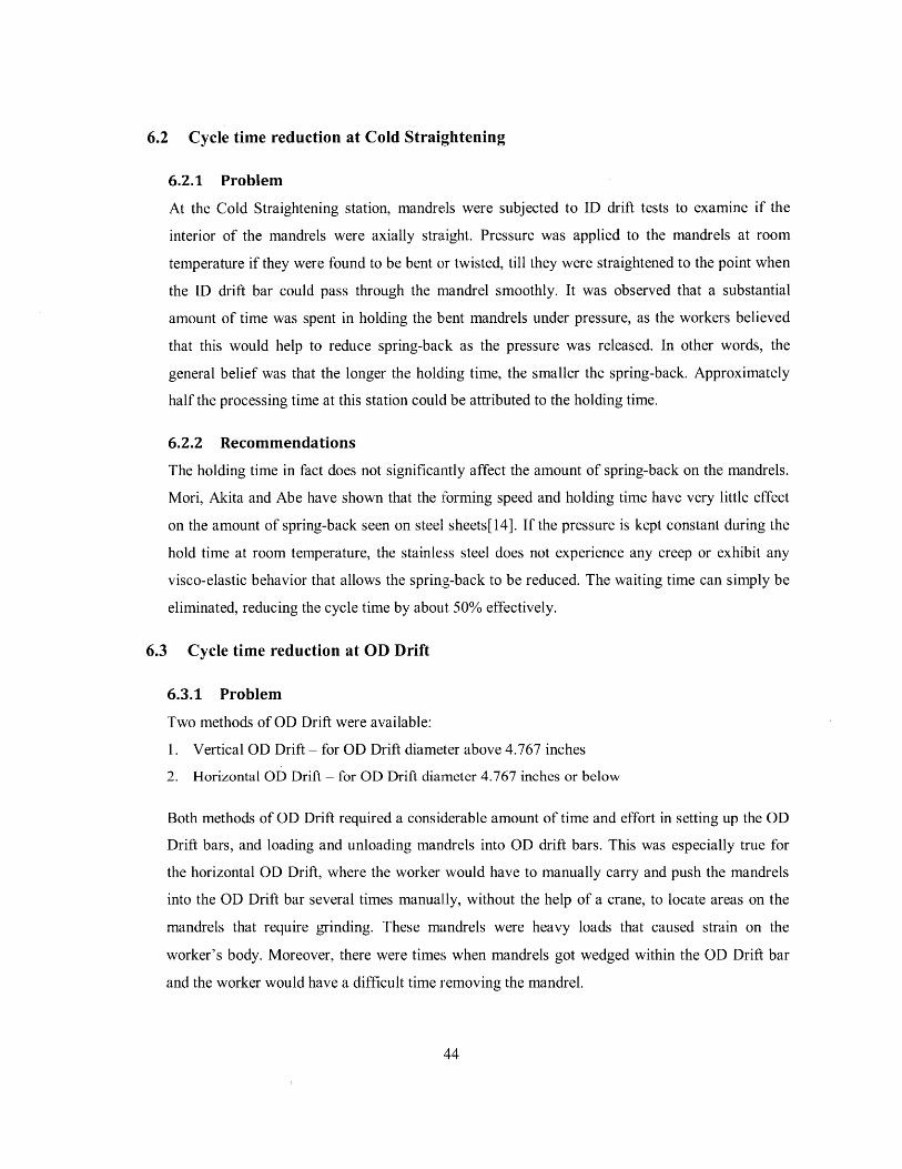
6.2 Cycle time reduction at Cold Straightening
6.2.1 Problem
At the Cold Straightening station, mandrels were subjected to ID drift tests to examine if the
interior of the mandrels were axially straight. Pressure was applied to the mandrels at room
temperature if they were found to be bent or twisted, till they were straightened to the point when
the ID drift bar could pass through the mandrel smoothly. It was observed that a substantial
amount of time was spent in holding the bent mandrels under pressure, as the workers believed
that this would help to reduce spring-back as the pressure was released. In other words, the
general belief was that the longer the holding time, the smaller the spring-back. Approximately
half the processing time at this station could be attributed to the holding time.
6.2.2 Recommendations
The holding time in fact does not significantly affect the amount of spring-back on the mandrels.
Mori, Akita and Abe have shown that the forming speed and holding time have very little effect
on the amount of spring-back seen on steel sheets[14]. If the pressure is kept constant during the
hold time at room temperature, the stainless steel does not experience any creep or exhibit any
visco-elastic behavior that allows the spring-back to be reduced. The waiting time can simply be
eliminated, reducing the cycle time by about 50% effectively.
6.3 Cycle time reduction at OD Drift
6.3.1 Problem
Two methods of OD Drift were available:
1. Vertical OD Drift - for OD Drift diameter above 4.767 inches
2. Horizontal OD Drift - for OD Drift diameter 4.767 inches or below
Both methods of OD Drift required a considerable amount of time and effort in setting up the OD
Drift bars, and loading and unloading mandrels into OD drift bars. This was especially true for
the horizontal OD Drift, where the worker would have to manually carry and push the mandrels
into the OD Drift bar several times manually, without the help of a crane, to locate areas on the
mandrels that require grinding. These mandrels were heavy loads that caused strain on the
worker's body. Moreover, there were times when mandrels got wedged within the OD Drift bar
and the worker would have a difficult time removing the mandrel.

6.3.2 RecommendationsA long wooden rule can be used as a gauge to check the straightness of mandrels and aid in
detecting areas to grind. This technique is not meant as a substitute to replace the OD Drift
process, as OD Drift is the most definite way of ensuring that the mandrels have an axially
straight exterior. The worker should still carry out the traditional OD Drift, but use the wooden
rule during the process to reduce the number of times he has to insert and remove the mandrels
from the OD Drift bar.
6.4 Verifying part routings before commencing operations
6.4.1 Problem
It has been observed that the routings were seldom checked just before/after work was done on
the mandrels, at most of the assembly and inspection stations. This caused some mandrels to be
processed with wrong tools or parameters. Costly consequences result, such as rework, scrap, or
customer complaints.
6.4.2 Possible causes
There are several plausible reasons why the routings are not checked before the mandrels were
processed at each of the work stations.
1. The operators do not wish to lose their momentum between mandrels. Immediately after they
complete one mandrel, they wish to start on the next one as soon as possible. This is
especially true for the hardness test, MPI, OD drift and cold straightening stations, as they
share a common crane. Once they unload a mandrel with the crane, they'll want to load
another mandrel onto their station before they lose possession of the crane. And once they
have a mandrel sitting in their station, they'll want to start working on it as soon as possible.
As a result, documentation work seems to get neglected.
2. The routings for assembly operations are all centralized at a shelf just beside the fit-up station.
It might have been designed this way because mandrels in a single work order are often split
up across different stations. Centralizing the location of routings will actually make them
easier to find and prevent the routings from getting lost. However, this also means that the
routings are a distance away from the individual work stations. This makes it a little
inconvenient for the operators to walk to and from their stations and the shelf of routings.
3. The operators are gaining experience from working in the shop floor, and they make
assumptions about the processing parameters from what they know about the mandrels.

Instead of referring to the routings, they'll recall what they have done to identical mandrels in
the past.
6.4.3 Recommendations
The workers can possibly be made to check the routings by enforcing discipline and more
importantly, letting them know why this procedure is important. Some of the operators do not
even know how the mandrels work out in the field; thus they are unable to link the importance of
their work to the final product. Educating them on this might improve their sense of pride and
quality of work.
Moreover, the routings can be made more accessible to the operators. Instead of centralizing the
routings, they can be made to flow with the mandrels. For example, for a work order of four
mandrels, four identical copies of the routings can be made and each of them stuffed into the
mandrels.
A barcode scanning system can also be installed in the shop floor. A barcode can be stuck or
stenciled (in brail form) onto each of the mandrels. Each station can have one of these barcode
scanning machines, or two stations can share one. When a mandrel arrives at a particular process,
the worker can simply scan the barcode on the mandrel and the parameters relevant to that
process will be shown to him. He can be asked to scan the mandrel again after the process is
complete on the mandrel; in this way, both the start and end times will be captured automatically
by the system. This barcode scanning system has numerous advantages:
1. Operators will not need to spend too much time on looking for routings or doing
documentation work. Scanning the barcode will retrieve the routings immediately for their
reference.
2. This system will be able to replace the Production Control Board entirely. The start and end
times of each mandrel will be entered accurately, and there will not be a need to type in the
entries manually every week.
3. Errors will be greatly reduced. Some mandrels are rather badly rusted and the stenciled
numbers become illegible. By eliminating reading, writing and manual typing of numbers,
there will be no wrong entries.
4. This system will provide real-time updates of where the mandrels are. The WIP board will
not have to be updated manually, and will definitely be more accurate.

5. Mandrels that are missing in the shop floor can be easily found. There were times when
mandrels get lost somewhere in the shop, and a lot of time is wasted on hunting for it. Such a
system will tell the management exactly where the mandrel was last processed.
7 Conclusion
7.1 Conclusion
This thesis has presented a practical framework for calculating the manpower plan of the Gas Lift
Mandrel assembly line to fulfill the projected demand of mandrels till the year 2013. Other than
suggesting the number of workers to employ, this thesis also considered the training and deployment
of workers across all processes in the assembly line.
Two manpower scheduling concepts were incorporated in the manpower plan, such as Job Rotation
and Workforce Flexibility to optimize the rate of utilization, human performance and well-being. In
particular, it has been shown that by clustering processes together and allowing the workers to move
across processes within each cluster, the utilization rate can be increased to more than ninety percent.
A new position of grinders has also been proposed to assist in various grinding operations in the
assembly line. By performing the grinding operations prior to the processes, these grinders help the
workers at individual processes focus better on the main operations in their work stations. Removing
the grinding operations from the main processes also effectively reduces the cycle times, making it
easier to achieve the Planned Cycle Times. In addition, since these grinders do not require special
skills like the other workers, they incur a lower cost of labor.
Other than manpower planning, this thesis has also identified several potential areas of improvement
to reduce the work content of processes. Specifically, they include eliminating the holding time at
Cold Straightening, utilizing a wooden rule at OD Drift to aid the worker in gauging the straightness
of mandrels and locate grinding areas, and implementing a barcode scanning system to display
routings.
7.2 Future Work
As more accurate forecasts of the projected demands are obtained over time, the manpower plans will
have to be revised with the methodology presented in this thesis. This will ensure that the right
number of workers are employed and deployed to each cluster to satisfy the rate of customer demand.
Proposed scheduling concepts such as workforce flexibility and job rotation should also be
implemented in these revised plans to bring about maximum worker utilization and productivity.
47

This thesis has also identified processes with high manual work contents, which can potentially be
shortened by continuous improvement projects. Some of these processes include Full Welding, ID
Welding and Round Mandrel Fit-up.
A process worthy of immediate investigation would be Cold Straightening, where there is prospective
time savings of up to 50%. An experiment should be carried out in the shop floor to determine if the
spring-back of mandrels is truly independent of the holding time. If the hypothesis is true, cycle time
of this process will be halved, and the worker can be freed up to work on other processes.

References
[1] Background of Schlumberger. May 2010 [cited 2010 21 June]; Available from:http://www.slb.com/about/who/backgrounder.aspx.
[2] K. Gowda, Manufacturing Engineer[3] P. P. Tee, Quality Engineer (values in graphic were modified by author)[4] M. Rother and J. Stock, Learning to See - Value-Stream Mapping to Create Value and Eliminate
Muda, 1.3 ed. Cambridge, Massachusetts: The Lean Enterprise Institute, Inc., 2003.[5] E. Molleman and J. Slomp, "Functional Flexibility and Team Performance.," International
Journal ofProduction Research, vol. 37(8), pp. 1837-1858, 1999.[6] W. J. Hopp, E. Tekin, and M. P. Van Oyen, "Benefits of skill chaining in production lines with
cross-trained workers.," Management Science, vol. 50:1, pp. 83-98, 2004.[7] J. Slomp and E. Molleman, "Cross-training polices and team performance.," International
Journal ofProduction Research, vol. 40(5), pp. 1193-1219, 2002.[8] I. Kuorinka and L. Forcier, Work related musculoskeletal disorders (WMSDs) : a reference book
for prevention. London; Bristol, PA: Taylor & Francis, 1995.[9] D. Liles, S. Deivanayagam, M. Ayoub, and P. Mahajan, "A job severity index for the evaluation
and control of lifting injury.," Human Factors, vol. 26(6), pp. 683-693, 1984.[10] J. W. Herrmann, Handbook ofproduction scheduling. New York: Springer, 2006.[11] B. D. Stewart, "Mathematical models for developing a flexible workforce," International Journal
ofProduction Economics, vol. 36, pp. 243-254, 1994.[12] A. Hertz, N. Lahrichi, and M. Widmer, "A flexible MILP model for multiple-shift workforce
planning under annualized hours," European Journal of Operational Research, vol. 200, pp. 860-873, 2009.
[13] D. Hardt, MIT Subject 2.830 Control of Manufacturing Processes Lecture 3 Notes, 2010.[14] K. Mori, K. Akita, and Y. Abe, "Springback behaviour in bending of ultra-high-strength steel
sheets using CNC servo press," International Journal of Machine Tools & Manufacture, vol. 47,pp. 321-325, 2007.

Appendix I - Compiled data of GLM assembly processes
Table I-1: Compiled data of GLM assembly processes
Specialised TaskGeneral Task
Specialised TaskGeneral Task
Steps Time (sec)Load upper swage 114Load discriminator 74Load lower swage 81Air blow 35Check drawings 281Inspect parts 400Align parts 1042Tack weld 3377Documentation 513Stencil numbers on mandrel 402Unload onto trolley 96
Total processing time(sec) 6415Total processing time(h:mm:ss) 1:46:55

Specialised TaskGeneral Task
Specialised TaskGeneral Task
Specialised TaskGeneral Task

Steps Time (eec) Tim. (sec) Time (ec) Time (ee Time (ec) Time (sec) Tim. (nec Time (sec)Load 80 122 106 96 71 99
Liftliack 120 65 82 79 85 43Tape ends and valve inlets 33 99 114 76 95 50Gindlowerswage 172 211 261 404 102 342Change sides 156 179 141 138 210 109Grind upper swage 276 298 174 436 297 491 288Ar blow 162 149 164 75 159 161 1081Bliw lurch and straighten 2021 2096 1123 2139 4198 3374 2535Unload 1051 140 116 75 82 74
Total processing timeleec) 31251 3359 2281 3518 5299 4743 incomplete data 21Total processing time(h:mm:ss) 0:52:051 0:55:59 0:38:01 0:58:38 1:28:19 1:19:03 Incomplete data 0:44
Specialised TaskGeneral Task
Specialised TaskGeneral Task
Specialised TaskGeneral Task

Steps Time (sec)Set u OD bars 1251Load and test mandrel 546Unload mandrel onto floor 170Load mandrel onto trolley 76
Total processing time(sec) 2043Total processing time(h:nmm:ss) 0:34:03
Specialised TaskGeneral Task
Specialised TaskGeneral Task
Specialised TaskGeneral Task

weps I Im (sac) Time (sec) I Imo (SOCI ilme (Sc) I Inle (SeqCLoad onto trolley 120 60 58 83Grind swages 60 60 78 95Oil and grind pocket 60 60 128 102 5Air blow 60 30 25 28Push trolly into test bay 60 30 36 47Load on bench & clamp 55 85 52 80 8Redress dummy valve 35 225 18 214 15!Install dummy valve 48 25 30 150 3Install plug on upper swage 110 134 90 80 7Fill with water 122 76 70 113 9(Install plug on lower swage 110 120 144 108 14$Bleed off bubbles 40 40 56 90Test 1077 840 994 1038 70'Remove plugs 143 120 118 158 91Remove dummy valve 40 73 48 80 11Drain water & blow 75 52 66 65ID drift 15 22 13 17 2(Put on red plugs and blue tape 60 60 45 65 2(Apply rust inhibitor on pocket 60 60 38 53 1Unload 120 60 56 40 5(Push the trolley out of test bay 35 25 30 48Inspection report (eQ & Monitoring) 45 53 60 47 201
Total processing time(sec) 2550 2310 2253 2801 1811,Total processing time(h:mnm:ss) 0:42:30 0:38:30 0:37:33 0:46:41 0:30:11
Specialised TaskGeneral Task
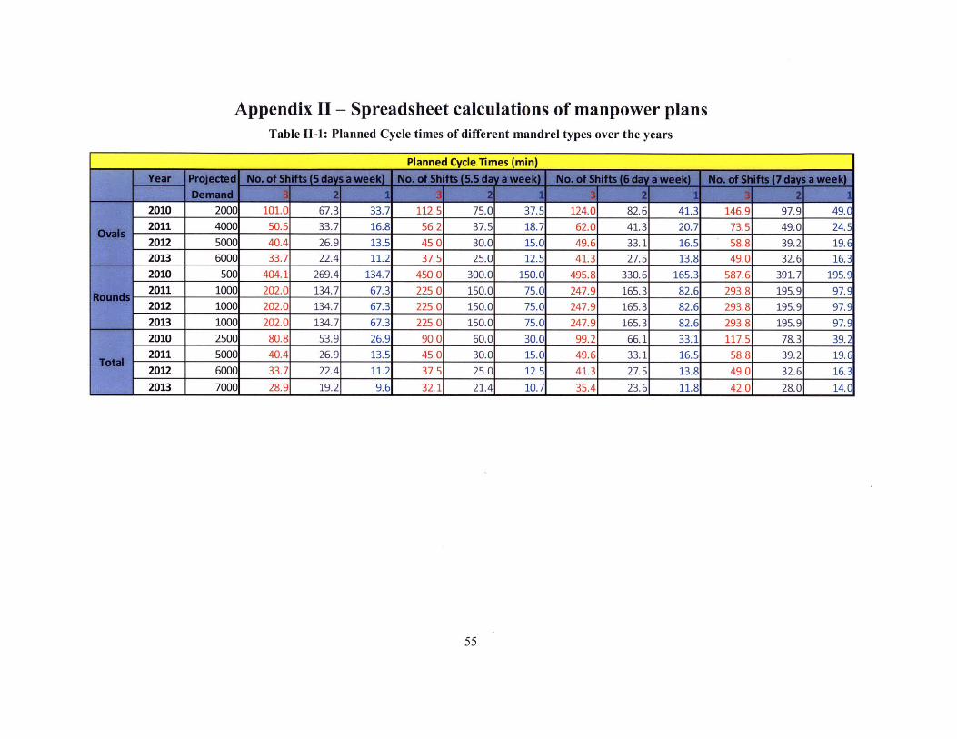
Appendix II - Spreadsheet calculations of manpower plansTable 11-1: Planned Cycle times of different mandrel types over the years
Planned Cycle Times (min)
2010 2000 101.0 67.3 33.7 112.5 75.0 37.5 124.0 82.6 41.3 146.9 97.9 49.02011 4000 50.5 33.7 16.8 56.2 37.5 18.7 62.0 41.3 20.7 73.5 49.0 24.52012 5000 40.4 26.9 13.5 45.0 30.0 15.0 49.6 33.1 16.5 58.8 39.2 19.62013 6000 33.7 22.4 11.2 37.5 25.0 12.5 41.3 27.5 13.8 49.0 32.6 16.32010 500 404.1 269.4 134.7 450.0 300.0 150.0 495.8 330.6 165.3 587.6 391.7 195.92011 1000 202.0 134.7 67.3 225.0 150.0 75.0 247.9 165.3 82.6 293.8 195.9 97.92012 1000 202.0 134.7 67.3 225.0 150.0 75.0 247.9 165.3 82.6 293.8 195.9 97.92013 1000 202.0 134.7 67.3 225.0 150.0 75.0 247.9 165.3 82.6 293.8 195.9 97.92010 2500 80.8 53.9 26.9 90.0 60.0 30.0 99.2 66.1 33.1 117.5 78.3 39.22011 5000 40.4 26.9 13.5 45.0 30.0 15.0 49.6 33.1 16.5 58.8 39.2 19.62012 6000 33.7 22.4 11.2 37.5 25.0 12.5 41.3 27.5 13.8 49.0 32.6 16.32013 7000 28.9 19.2 9.6 32.1 21.4 10.7 35.4 23.6 11.8 42.0 28.0 14.0

Table 11-2: Calculations of manpower plans
2010 Work Content (min) !8.5 :
PCT 185.7 191I.1 121./I 121./ 155!.9 6 8.4No of workers per shift 1 1 4 1 1 1Actual Planned cycle time 185.7 191.1 486.6 121.7 155.9 68.4
Total workers 26
PCT 182.0 91.0 56.6 37.7 47.7 31.8 47.7 79.5 79.5 28.6 42.9No of workers pershift 1 1 1 1 9 2 1 2 2 1 1 Total workers 56
2011 Actual Planned cycle time 182.0 91.0 56.6 37.7 429.41 63.6 63.61 79.5 28.6 42.9
PCT 202.0 67.3 42.1 42.1 14.0 35.4 35.4 23.6 35.4 35.4 70.9No of workers per shift 1 1 1 1 1 12 2 2 2 2 1 Total workers 75
2012 Actual Planned cycle time 202.0 67.3 42.1 42.11 14.0 425.2 118.1 70.9 70.9 70.9
PCT 187.5 62.5 37.5 25.0 12.5 31.2 31.2 52.1 72.9 31.2 62.5No of workers per shift 1 1 1 2 1 14 2 1 1 2 1 Total workers 82
2013 Actual Planned cycle time 187.5 62.5 37.5 50.0 12.5 437.5 114.6 72.9 62.5 62.5
Baseline(6/7 daysa week)