Manos Juntas - WordPress.com
17
Manos Juntas School Desk Project Instructions For Building a Desk February 2014
Transcript of Manos Juntas - WordPress.com
Manos Juntas School Desk Project
Instructions For Building a Desk
February 2014

Page 2
Table of Contents
Introduction ....................................................................................................................... 3
Overview of Material Needed And Estimated Cost Per Desk ............................................. 4
Description of 1” x 4” Pieces ............................................................................................. 5
Other Materials Needed ..................................................................................................... 6
Tools Needed ..................................................................................................................... 7
How To Assemble Desk ..................................................................................................... 8
Building Material Options ............................................................................................... 16
Parts and Dimensions ....................................................................................................... 17

Page 3
Introduction
Manos Juntas Ministry in Mexico is establishing new schools for children all
along the Texas-Mexico border. The Director of Manos Juntas, Willie Berman,
is a Methodist Missionary in Reynosa Mexico. Willie says they need 40-50
school desks for the children that will be coming to these new schools, and is
asking Methodist Churches to build these desks and make them available to his
Ministry. Willie has asked that the school desks be built as per the instructions
in this booklet.
The design of this desk was largely based on the Junior School Desk design
developed by the Methodist Midwest Mission Distribution Center (MMDC) in
Chatham, IL. This Center is part of the UMCOR Network in the U.S. Many
thanks to the MMDC for their help with this project.

Page 4
Overview of Material Needed And
Estimated Cost Per Desk
The above estimated costs assume that the materials are purchased in bulk
where applicable, and does not included sales tax. These costs were taken from
actual purchase costs from local stores in Houston Texas (Home Depot, Lowes,
Ace Hardware, etc.)
Material Quantity Estimated Cost
1"x4" No 2 Pine or Better 5 boards (8') $22.00
3/4" MDF w/melamine facing Desk & Seat $13.00
1/4" MDF Desk Encloser-Bottom $7.15
3" Standard Hinge 2 $5.25
Carriage Bolts (28) 28 $5.05
Flat Washers for Bolts (28) 28 $2.50
Nuts for Carriage Bolts (28) 28 $1.50
Drywall Screws - 1 1/4" 30 $0.10
Drywall Screws - 1 5/8" 45 $0.10
Polyurethane Stain/Lacqure Small Portion of Pt. Can $1.20
Desk Top Lid Support 1 $3.00
L Brackets - 1 1/2" 8 (2 packages of 4) $5.00
Estimated Cost of Materials --> $65.85

Page 5
Description of 1” x 4” Pieces
Lengths (inches)
Description Decimal Fraction
Desk Leg 24.25 24 1/4
Desk Leg 24.25 24 1/4
Desk Leg 24.25 24 1/4
Desk Leg 24.25 24 1/4
Front leg brace for Desk 45.25 45 1/4
Frnt 'box support for Desk top' 43.75 43 3/4
Back 'box support for Desk top' 43.75 43 3/4
Side of 'box support for Desk top' 17.25 17 1/4
Side of 'box support for Desk top' 17.25 17 1/4
Vertical leg for seat 14.25 14 1/4
Vertical leg for seat 14.25 14 1/4
Horizontal seat supports 8.875 8 7/8
Horizontal seat supports 8.875 8 7/8
Seat support between 2 legs 43.75 43 3/4
450 Angle supports for Seat 15.2 15 3/16
450 Angle supports for Seat 15.2 15 3/16
Floor Level Tie: Desk to Seat 30.25 30 1/4
Floor Level Tie: Desk to Seat 30.25 30 1/4
Table above shows all the 1”x4” pieces that need to be cut. Table at left shows a recommended pattern on how to cut the five required 8’ boards. All 1”x4” should be No. 2 Pine or better in quality.
1 2 3 4 5
24 1/4 45 1/4 43 3/4 43 3/4 43 3/4
24 1/4 24 1/4 17 1/4 30 1/4 30 1/4
24 1/4 17 1/4 14 1/4 15 3/16 15 3/16
8 7/8 14 1/4
8 7/8
90 1/2 86 3/4 89 1/2 89 3/16 89 3/16
1"x4"x8' Boards

Page 6
Other Materials Needed
Cautions
The ¾” MDF w/melamine facing (double sided) is most economical to buy in 49” x
97” sheets and then cut pieces for the seat and desk top. One sheet is enough for all
needed pieces for 3 desks plus an extra fixed base for hinges (5” x 48”) and/or extra
seat (9” x 48”). It is best to use a blade that has a ‘large number of smaller teeth’
which is designed for cutting this material (i.e. blade with 40-60 smaller teeth on a 7
¼” blade for skill saw). If this material is cut with a more standard blade (i.e. multi-
purpose or framing blade) the melamine along the cut edge will likely be very chipped).
When buying the L brackets and Hinges, ensure that the screws that come with these
are 5/8” – ¾” in length so as not to go all the way through the 1” x 4” or ¾” MDF.
Description Material or Size Dimensions
Seat 3/4" MDF w/melamine facing 9" x 48"
Desk Top - Fixed Base for
Hinges
3/4" MDF w/melamine facing 5" x 48"
Desk Top - Hinged Lid 3/4" MDF w/melamine facing 13" x 48"
Desk Enclosure - Bottom 1/4" MDF 15 1/8" x 45 1/8"
L Brackets (8) 1 1/2" --
Hinges (2) 3" Standard Hinge --
Desk Top Lid Support (1) Metal Friction/Folding
Support
--
Carriage Bolts (28) 1/4" x 1 3/4" --
Flat Washers for Bolts (28) 1/4" --
Nuts for Carriage Bolts (28) 1/4" --
Drywall Screws (~25) 1 1/4" --
Drywall Screws (~25) 1 5/8" --
Polyurethane Stain/Lacquer Small portion of Pt. Can --
13”
13”
13”
9”
9”
9”
5”
5”
5”
Appro
x. 15”
+/-
extr
a
4’ x 8’ Sheet of
MDF w/melamine
facing

Page 7
Tools Needed
Power Drill/Driver with assorted drill bits and bits for Phillips head screws
Small square
Carpenter’s square
Skill saw with o blade for cutting 1” x 4” (standard blades will work) o blade for cutting the MDF with melamine facing (best to have blade
with large number of small teeth, ie. for 7 ¼” blade this would be 140 teeth; standard blade will not cut the MDF w/melamine as clean and chip the melamine along the cut edge)
Hammer
Clamps (2 -4) Ratchet socket wrench or Open end wrench
Steel tape measure
Bit for countersinking drywall screws
Paint brushes
Small Level
Sandpaper Pencil
Tools That Are Helpful To Have Power Miter Saw 2nd Power Drill/Driver or Power Impact Driver Table Saw for cutting MDF with melamine facing; need blade with
high density of teeth Power sander

Page 8
<- 15 1/8” ->
<-- 17 1/4” -->
300
How To Assemble Desk
The 1st step is to assemble the ‘box’ on which the desk top will be attached. This is to be
made from the 1” x 4” front and back box supports for the desk top (43 3/4”) and the 2
sides of the box support (17 1/4”). Before assembling, cut one
end of each of the side supports at a 30 degree angle. See
drawing at right.
Set the 2 sides on a flat surface far enough apart to place the front and back support pieces
in between them. Line up the back support piece with the square end of the side pieces
and use a square to make sure the corner is square. Attach these 3 pieces using 3 drywall
screws in both corners (use 1 5/8”
screws). It is best to pre-drill and
countersink a hole for each screw
before applying to reduce splintering
of wood and ensure screw head is
safely below wood surface. Next
line up the outside of the front
support piece adjacent to the ‘shorter
corner’ (~ 15 1/8”) of the side
supports and attach with 3 drywall
screws as done above. Use square
to ensure that the corners are square.
See picture at right.
Next attach the ‘fixed desk piece’ (5” x 48”) to the desk
support box just assembled. Place the ‘fixed desk piece’
topside down and lay the support box upside down on top of
it. Center the support box long wise on the ‘fixed desk piece’
and line up the back side of the support box parallel to the
back and 5/8” from the back edge. Once in place, use the
clamps to firmly hold the two pieces together. Connect these
two pieces together using 4 L brackets. It is recommended
that you place 1 bracket adjacent to each side support piece
and space the remaining two brackets along the back support
piece. Use the screws that came with the L brackets to
connect these two pieces together. Be sure that the screws are not longer than about ¾” so
they do not go all the way through the desk top or the 1” x 4”. It is recommended that the
screw holes in the desk top be predrilled. See picture above.
Side piece
Back and Front supports

Page 9
Fro
nt
leg
Next attach the four legs of the desk (1”x4”x24 ¼”) to the corners of the desk top support
box just assembled. The front two legs should be attached on the outside and lined up
flush with the front corners of the support box, not the front edge of the
‘fixed desk piece’. Use the carriage bolts to attach the legs. Clamp the
legs to the support box ensuring that they are square with the bottom of
the support box. Once a leg is clamped in place, drill two ¼” holes
through leg and side of support box in which carriage bolts will be
inserted. It is recommended that the 2 holes be drilled in a ‘diagonal’
pattern (see picture at right). Be careful in placement of holes for the
carriage bolts to ensure that there is sufficient room inside support box
to work with flat washers and nuts that must be attached to bolts. Insert
carriage bolts from outside such that washer and nut is inside desk
enclosure.
After front legs are attached, attach back 2 legs in a similar manner. Again line up the
back legs ensuring that they are square with the support box AND also lined up adjacent to
the ‘shorter corner’ (~ 15 1/8”) of the side support pieces. Drill ¼” holes for 2 carriage
bolts in diagonal pattern ensuring that there is sufficient room inside of support box to
work with the flat washers and nuts that must be attached to bolts. Again insert bolts from
outside such that washer and nuts are inside desk enclosure. See picture above.
Bac
k l
eg
Page 10
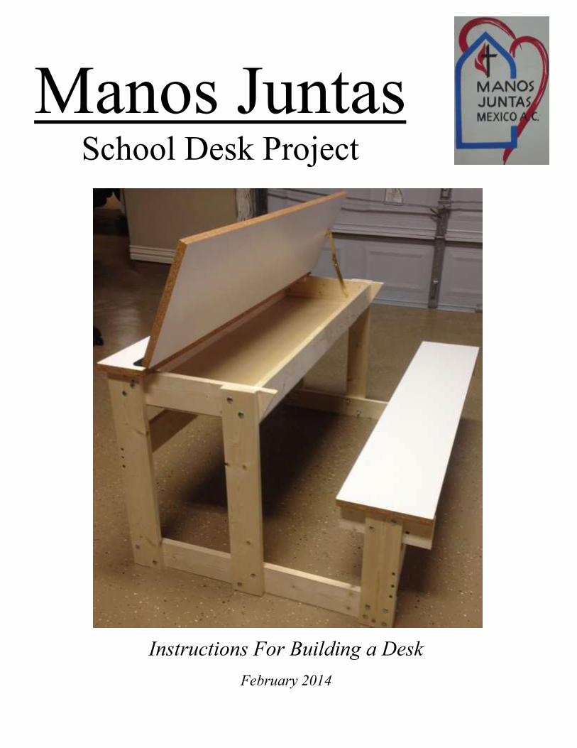
After 4 legs of desk are attached then attach bottom of the desk enclosure. Cut this piece
from ¼” MDF board and it should be 15 1/8” x 45 1/8”. Once it is cut, center on the
bottom of the desk and attach with 1 ¼”
drywall screws. It is recommended that all
the screw holes be predrilled and countersunk
to prevent wood splits as well as ensure that
the heads of the screws are flush or below the
surface of the ¼” MDF. Use approximately 3
screws along the sides of the desk and 5 along
the front and back. See picture at right.
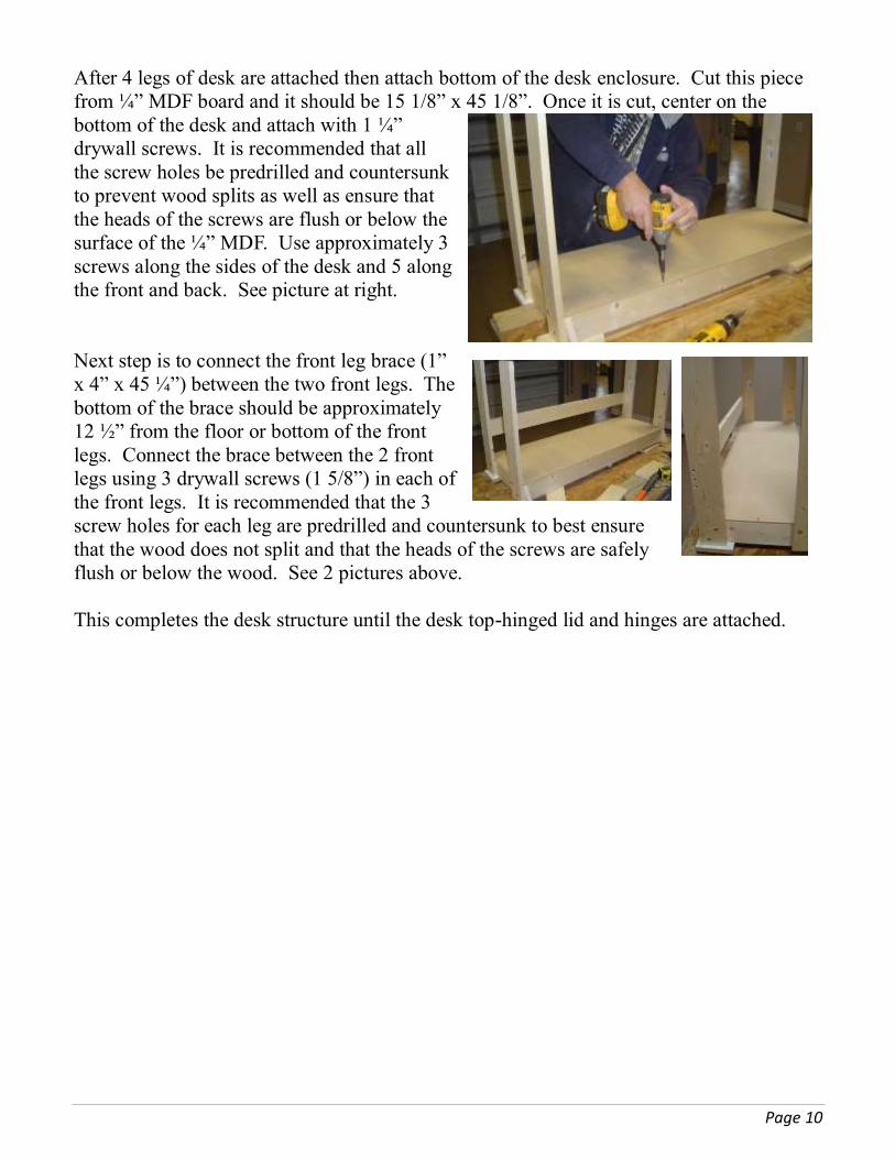
Next step is to connect the front leg brace (1”
x 4” x 45 ¼”) between the two front legs. The
bottom of the brace should be approximately
12 ½” from the floor or bottom of the front
legs. Connect the brace between the 2 front
legs using 3 drywall screws (1 5/8”) in each of
the front legs. It is recommended that the 3
screw holes for each leg are predrilled and countersunk to best ensure
that the wood does not split and that the heads of the screws are safely
flush or below the wood. See 2 pictures above.
This completes the desk structure until the desk top-hinged lid and hinges are attached.

Page 11
Next step is to build the support structure for the seat. First step is to connect the seat
support between the 2 legs (1” x 4” x 43 ¾”) to the 2
horizontal seat supports (1” x 4” x 8 7/8”). Mark the center
of the horizontal seat supports on one edge and the center of
the support structure for the seat and line up the center marks
as shown in the picture to right and attach the two pieces
using 3 drywall screws (1 5/8”) on each end. As above, it is
recommended that the screw holes are predrilled and
countersunk. Use square to ensure two pieces are
perpendicular.
NOTE: See ‘Modification made to horizontal seat supports’ shown on next page.
Next step is to attach the two vertical legs for seat (1”
x 4” x 14 ¼”) to the ends of the seat support structure
assembled above. Mark the center of the legs and line
the center up with the center of the horizontal seat
supports from above. Use square to ensure that legs
are perpendicular to horizontal seat support. Clamp
into place once lined up. Drill two1/4” holes on diagnal pattern for two carriage bolts to
attach the two pieces together. Insert carriage bolts from outside such that the washer and
nut are under the seat when completed.
Next step is to attach the completed seat support structure to the seat (9” x 48” of ¾” MDF
w/melamine facing). Center the seat support structure on the seat (seat is top down as
shown in pictures). Once centered in both directions firmly clamp the two pieces together.
Then connect the two pieces together with four L brackets described
on page 5. Connect one L bracket to a horizontal seat support on
each end of the seat support structure and space out the remaining
two along the seat support between the 2 legs. The L brackets along
the seat support between the two legs should be placed around 11” –
12” from the horizontal seat supports to ensure that they do not get
in the way of attaching the 450 angle supports for the seat, which is
the next step. It is recommended that the L bracket screw holes
going into the bottom of the seat be predrilled with a small bit and
only ½” or less to ensure that the seat material does not chip or
breakaway when tightening screws. Also make sure screws for L
brackets are not over ¾” in length or they will go all the way
through the seat and 1” x 4”.

Page 12
<- 15 3/16” ->
450 angles Next step is to attach the two 450 angle supports for the seat. These pieces are 15 3/16” long and cut at 450 angles on each end. See sketch at right.
Attach these two supports to bottom side of seat as shown in the picture at right. Use 3 drywall screws (use 1 ¼” and 1 5/8” screws, but ensure that screws do not go all the way through the 450 angle support) to attach this piece to the vertical seat legs. It is recommended that each screw hole is predrilled and countersunk to ensure the wood does not split and the head of the screw is flush or below the surface of the wood. Similarly attach the 450 angle piece to the horizontal seat support using 3 drywall screws (only use 1 ¼” screws for this). It is recommended that each screw hole is predrilled and countersunk to ensure the wood does not split and the head of the screw is flush or below the surface of the wood. Modification made to horizontal seat supports (1” x 4” x 8 7/8”): It is recommended
that the 2 horizontal support pieces be slightly modified from the
above pictures for safety reasons. In order to remove the sharp
corner exposed at the
bottom of the seat support
structure, the bottom
corners of these two pieces
are to be cut as shown in
the sketch and pictures at
right. All other assembly instructions shown on pages 11 and 12
are unchanged.
Assembled Seat Support
Structure Shown Upside Down
with Modified Horizontal Seat
Support
<- 8 7/8” ->
3/4” ->
< 2 1/2” >

Page 13
Next step is to attach the desk top-hinged lid (13” x 48” piece of 3/4" MDF w/melamine
facing) to the desk top-fixed base (5” x 48” piece of 3/4" MDF w/melamine facing) that
was previously attached to the desk. The 2
pieces of the desk top are connected by the
hinges. Set the hinged lid piece on the desk
structure that was completed earlier. Make sure
that the side edges of the fixed base and the
hinged lid pieces are flush. Then set the 3”
hinges over the break between these two pieces
as shown in the picture at right. The hinges on
each side should be the same distance from the
side edges, about ¾”. Place the hinge over the
gap between the 2 pieces such that the pin of the
hinge is completely resting on the fixed base
piece and lined up with the gap, see picture.
Connect the hinge to the fixed base piece first. It is
recommended that care be taken when attaching the hinges to
both pieces. After the hinges are in place, mark the center of the
screw holes with a pencil, then use a punch to indent the desk
top pieces, and then predrill a small and shallow hole for each
screw. Taking this care will better ensure that the hinges will be
in the proper place when the screws are tightened. Attach both
hinges to the fixed base piece then to the hinged lid piece.
Ensure screws that come with hinges are ¾” or less in
length so that they do not go all the way through the
desk top pieces.
Fixed base piece Hinged lid piece

Page 14
Next step is to attach the floor level tie (1” x 4”
x 30 ¼”) between the desk structure and the
seat structure. Attach the floor level tie to the
front legs first. Line up the tie inside the legs
and flush with the front edge of the legs. Use a
small square to ensure that the legs and the
floor level tie piece are perpendicular to edge
other. Once pieces are lined up properly, use
clamps to hold the two pieces in place and drill
two ¼” holes for carriage bolts. Holes should be drilled in a diagonal. Insert the carriage
bolts from the outside, and attach a washer and nut on each.
After the front leg(s) are attached to the tie piece,
attach to the back leg(s) of the desk structure. Use a
square to make sure that the back legs are
perpendicular with the tie piece, then clamp in place.
Drill ¼” holes on diagonal for carriage bolts. Insert
bolts from the outside and attach a washer and nut on
each.
Next step is to attach the seat structure to the floor tie piece. Line up the back of the seat
leg flush with the back of the floor tie piece. Use a
small square to ensure that the seat leg is
perpendicular to the floor tie piece. Once in place,
use clamps to hold them in place when drilling ¼”
holes for the carriage bolts. Connect these two
pieces using 4 carriage bolts in a ‘square’ pattern.
Insert the carriage bolts from the outside and attach
a washer and nut to each.
The picture at right shows the desk structure and
the seat structure attached to the floor tie piece. All
carriage bolts are inserted from the outside and
securely tightened. Also shown is the two desk top
pieces attached by the hinges

Page 15
Next step is to attach a ‘lid support’ of some type to the hinged desk top piece to enable the
lid to be supported in the open position. This
simple hardware will help prevent fingers
and hands from being pinched by a falling
desk lid.
There are many types of these supports
available in most hardware stores. The one
shown in the picture at right is simply called
a “Lid Support Hinge”. It folds in half when
the desk is closed and can be ‘locked’ open
as shown here. An option also is spring
loaded hinges; most of these are more
expensive but should work fine also if the
springs are strong enough to lift/support the
weight of the desk lid.
Final step is to ensure that all edges of 1” x 4” and desk top pieces are sanded and smooth.
Please ensure that any sharp edges are smoothed and any places that could cause a child to
get a splinter are sanded and smooth. Use of a power sander can save time if available.
Around edges of desk top and seat (of the 3/4” MDF with Melamine facing) it is added
safety to paint them with a polyurethane or lacquer to seal the edges and prevent future
splintering or pealing. Cover these edges with at least 1 coat and preferably 2 coats.

Page 16
Building Material Options
1. Carriage Bolts: use of ¼” x 1 ¾” carriage bolts are recommended. They can be
hard to find at some popular hardware stores. These stores frequently carry 1 ½”
and 2” bolts, but not 1 ¾”. If you use 2” carriage bolts, they
do ‘stick out’ about ½” after washer and nut are attached.
This leaves a potentially dangerous length of the bolt exposed
for children’s hands or feet to come in contact with. It is
recommended that if 2” bolts are used, each bolt should be
capped with a protective plastic cap of some kind. In the
picture at right see a protective cap installed on 2” bolts that
are ‘small shelf caps’ that are used on cut ends of metal shelving. These are
available at most stores that sell ‘do it yourself’ metal shelving and they cost about
$0.06 each when bought in a bulk package of 100.
2. Hinges: these instructions include the use of two 3” standard hinges for attaching
the two desk top pieces together. Another option is to use one or two ‘continuous
hinges’ (sometimes called ‘piano hinges’) that are strong enough to securely support
the hinged lid piece and will not wear out with use. These hinges are more
expensive than the standard hinges.
3. Desk Top Material: These instructions include the use of ¾” MDF with melamine
facing on both sides. The melamine is a very smooth surface that is resistant to
moisture and scuffing. This material is usually used for ‘do it yourself’ shelving.
An option is to use ¾” MDF without the melamine facing, but this would need to be
sanded and coated with a polyurethane or lacquer to make it smooth and resistant to
moisture and ‘wear and tear’. Another option would be to use ¾” MDF with
melamine facing on one side only, and ensure that the melamine facing is on the top
of the desk and seat.

Page 17
Parts and Dimensions
Seat leg- 1” x 4” x 14 ¼”
Horizontal Seat Support- 1” x 4” x 8 7/8”
Desk Top-Fixed Piece- 5” x 48”
Desk Top-Hinged Piece- 13” x 48”
Desk Front Leg- 1” x 4” x24 ¼”
Desk Back Leg- 1” x 4” x24 ¼”
Floor Level Tie- 1” x 4” x30 ¼”
Box Support Side Piece- 1” x 4”
x 17 ¾”
Height of Desk- 25 ” Height of Seat- 15 ”
Box Support Front Piece- 1” x
4” x 43 ¾”
Desk Top Folding Hinge Support
Bottom of Desk Enclosure