
Manipulating Triplets in Organic Semiconductors
252
Manipulating Triplets in Organic Semiconductors David Martin Eric Freeman A thesis submitted in part fulfilment towards the award of Doctor of Philosophy UCL Under the Supervision of Dr. Hugo Bronstein
Transcript of Manipulating Triplets in Organic Semiconductors

Manipulating Triplets in Organic
Semiconductors
David Martin Eric Freeman
A thesis submitted in part fulfilment towards the award of
Doctor of Philosophy
UCL
Under the Supervision of Dr. Hugo Bronstein

ii

iii
I, David Martin Eric Freeman, confirm that the work presented in this thesis is my own. Where information has been derived from other sources, I confirm that this has been indicated in the thesis.

iv

v
Abstract
Triplet states in organic semiconducting devices are often associated with loss processes.
Radiative decay to the ground state is a spin disallowed process, which results in triplets in
normal organic systems decaying primarily though non-radiative pathways. In OLEDs, where
75% of created excitons are triplets, this has a large impact on device efficiency.
The work herein focusses on the synthesis of organic polymers that utilise triplet states in
some useful fashion. This was first achieved through incorporation of a heavy metal in the
polymer chain, which increased spin-orbit coupling and allowed phosphorescence to occur.
The heavy metal was incorporated directly into the polymer backbone as part of a porphyrin
complex.
Focus then moved to organic polymers that have decreased first excited singlet-triplet energy
gaps. This allows excitons to move from singlet to triplet state without the use of a heavy
metal, a formally spin disallowed process. Thermally activated delayed fluorescence is
observed in one polymer.
All synthetic work carried out is linked by the aim of using triplet states usefully in a resultant
device. While the applications of the devices may differ, all in some way use triplet states in
the movement of energy through the electronic system of the polymer. It is hoped that some
of this work may form the basis of new types of materials for organic semiconducting systems.

vi
Impact Statement
Three publications have resulted directly from the work presented herein. At the time of
submission, these works have generated 20 citations and thousands of individual page views
(as of 06/06/18). The work has been presented at domestic and international scientific
conferences which were attended by leaders in the fields of polymer synthesis and organic
electronics as physicists, chemists and materials scientists.
The development of OLED technology has already shown benefits to society as a whole and is
employed by many companies in marketable products. The further development of organic
electronic materials therefore has obvious benefits in a non-academic setting. It is hoped this
work may lead to further increases in efficiency for light emitting organic polymers and more
efficient, more eco-friendly devices.
vii
Table of Contents
Abstract .................................................................................................................................. v
Impact Statement ................................................................................................................. vi
Contributions ........................................................................................................................ ix
Acknowledgments.................................................................................................................. x
Publications ........................................................................................................................... xi
List of Abbreviations ............................................................................................................ xii
Chapter 1: Introduction .................................................................................................... 2
1.1 Polymers .................................................................................................................... 2
1.2 Organic Semiconducting Devices ............................................................................... 6
1.3 Triplet states in Organic Semiconductors ................................................................ 13
1.4 Porphyrins ................................................................................................................ 20
Chapter 2: Phosphorescent Polymers: Incorporating a Covalently Bound Porphyrin in Polymers ....................................................................................................................... 24
2.1 Introduction ................................................................................................................... 24
2.2 A Platinum Containing Polyfluorene for Phosphorescent Emission: PF MPP(Pt) .......... 28
2.3 Towards a Triplet-triplet Annihilation Polymer: PDPA MPP(Pt) .................................... 40
2.4 Conclusions .................................................................................................................... 52
Chapter 3: Low Energy Triplet Formation for TTA Polymers: Extended Porphyrins ........... 54
3.1 Introduction ................................................................................................................... 54
3.2 Synthesis of Extended Porphyrins ................................................................................. 58
3.3 Conclusions .................................................................................................................... 74
Chapter 4: Reducing the Singlet-Triplet Energy Gap: Donor-Orthogonal Acceptor Polymers...................................................................................................................................... 78
4.1 Introduction ................................................................................................................... 78
4.2 Synthesis of SFCN and SFH ............................................................................................. 89
4.3 Synthesis of ASFCN and ASFH ........................................................................................ 96
4.4 Physical and Optical Properties of SFH, SFCN, ASFH and ASFCN ................................. 104
4.5 Conclusions .................................................................................................................. 112
Chapter 5: Circularly Polarised Light Emitting Polymers: Synthesis of Chiral Monomers . 116
5.1 Introduction ................................................................................................................. 116
5.2 Synthesis of AB Ring System ........................................................................................ 119
5.3 Synthesis of CD Ring System and Chiral Spiro Monomer ............................................ 126
5.4 Conclusions .................................................................................................................. 133
Chapter 6: Experimental ............................................................................................... 136

viii
6.1 General Procedures ..................................................................................................... 136
6.2 Synthetic Techniques for Chapter 2 ............................................................................. 141
6.3 Synthetic Techniques for Chapter 3 ............................................................................. 151
6.4 Synthetic Techniques for Chapter 4 ............................................................................. 170
6.5 Synthetic Techniques for Chapter 5 ............................................................................. 186
References ................................................................................................................... 200
Appendices .................................................................................................................. 208
Appendix 1: Deep-red electrophosphorescence from a platinum(II)–porphyrin complex copolymerised with polyfluorene for efficient energy transfer and triplet harvesting ..... 208
Appendix 2: Highly red-shifted NIR emission from a novel anthracene conjugated polymer backbone containing Pt(II) porphyrins ............................................................................... 218
Appendix 3: Synthesis and Exciton Dynamics of Donor-Orthogonal Acceptor Conjugated Polymers: Reducing the Singlet–Triplet Energy Gap ......................................................... 230
ix
Contributions
Collaboration with other groups was a large part of this body of work. As a synthetic chemist,
I have relied on physicists, physical chemists and materials scientists to process my polymers
into devices and perform complex measurements that I was not equipped for. Where
appropriate, figures or data that have been obtained by someone other than myself have been
labelled in the text.
Chapter 2: Giulia Tregnago and Alessandro Minotto in Franco Cacialli’s group in the UCL
physics department performed device fabrication and measurements on the PF MPP(Pt) and
PDPA MPP(Pt) polymers respectively.
Chapter 3: Jordan Shaikh in Tracey Clarke’s group in the UCL chemistry department performed
physical testing of HAPPAP F8BT. His work has not been directly discussed in this text as it is
ongoing.
Chapter 4: Andrew Musser in Richard Friend’s group in the Cambridge physics department
performed device fabrication and measurements on SFH, SFCN, ASFH and ASFCN. Jarvist Frost
in the Imperial chemistry department performed computational calculations.

x
Acknowledgments
Thank you to Hugo Bronstein, who has been an excellent supervisor throughout my PhD. Your
unique supervisorial style is in my opinion the very best way to conduct research. I have
enjoyed myself immensely and learned a great deal, this is in large part thanks to you.
Thanks also to Kealan Fallon, you probably would have preferred a longer acknowledgment.
Thank you to Tom Waugh, since you like gimmicky things, here is a haiku. Oliver Ware has
been around since I started, I would like to thank him for the times he wasn’t.
Past and present members of the Bronstein group, thank you to all. Anastasia, Alex and Niall
especially, you have all made UCL a better place by your presence, I don’t care what everyone
else says.
Thanks family. Hi Mum, you don’t have to read the whole thing.
The following work has been in part paid for by the generous donations of the Johanna Eaden
foundation for impoverished boyfriends.

xi
Publications
Chapter 2 – Appendices I and II
Freeman D. M. E., Minotto A., Duffy W., Fallon K. J., McCulloch I., Cacialli F., Bronstein H. “Highly red-shifted NIR emission from a novel anthracene conjugated polymer backbone containing Pt(II) porphyrins”, Polym. Chem., 2016, 7, 722-730
Freeman D. M. E., Tregnago G., Rodriguez S. A., Fallon K. J., Cacialli F., Bronstein H. “Deep-red electrophosphorescence from a platinum(II)–porphyrin complex copolymerised with polyfluorene for efficient energy transfer and triplet harvesting”, J. Org. Semiconductors, 2015, 3, (1), 1-7
Chapter 4 – Appendix III
Freeman D. M. E., Musser A., Frost J., Stern H., Fallon K. J., McCulloch I., Clarke T., Friend R., Bronstein H. “Donor-Orthogonal Acceptor Conjugated Polymers: Reducing the Singlet-Triplet Energy Gap in Conjugated Polymers”, J. Am. Chem. Soc., 2017, 139 (32), pp 11073–11080
As Contributing Author
• Lin, Y. L.; Koch, M.; Brigeman, A. N.; Freeman, D. M. E.; Zhao, L.; Bronstein, H.; Giebink, N. C.; Scholes, G. D.; Rand, B. P. “Enhanced sub-bandgap efficiency of a solid-state organic intermediate band solar cell using triplet–triplet annihilation”, Energy Environ Sci, 2017, 10, 1465-1475
• Fallon K. J., Santala A., Wijeyasinghe N., Manley E. F., Goodeal N., Leventis A., Freeman D. M. E., Al-Hashimi M., Chen L. X., Marks T. J., Anthopoulos T. D., Bronstein H., “Effect of Alkyl Chain Branching Point on 3D Crystallinity in High N-type Mobility Indolonaphthyridine Polymers”, Adv. Funct. Mater., 2017, 1704069
• Fallon K. J., Wijeyasinghe N., Manley E. F., Dimitrov S. D., Yousaf S. A., Ashraf R. S., Duffy W., Freeman D. M. E., Al-Hashimi M., Durrant J. R., Chen L. X., McCulloch I., Marks T. J., Clarke T., Anthopoulos T. D., Bronstein H. “Indolo-naphthyridine-6,13-dione thiophene (INDT) building block for conjugated polymer electronics: Molecular origin of ultra-high n-type mobility”, Chem. Mater., 2016, 28, (22), 8366–8378
• Fallon K. J., Wijeyasinghe N., Yaacobi-Gross N., Ashraf R. S., Freeman D. M. E., Palgrave R. G., Al-Hashimi M., Marks T. J., McCulloch I., Anthopoulos T. D., Bronstein H. “A Nature-Inspired Conjugated Polymer for High Performance Transistors and Solar Cells”, Macromolecules, 2015, 48, (15), 5148–5154
xii
List of Abbreviations
°C Degrees centigrade
µL Microlitre
µs Microsecond
3D 3 dimensional
Ac Acetyl
acac Acetylacetone
AD Asymmetric dihydroxylation
AIBN Azobisisobutyronitrile
Ar Aromatic group
ASFCN Poly-4’,4’’-(4-(2-octyldodecyl)-N,N-
diphenylaniline)-alt-2,7-(9,9'-
spirobi[fluorene]-2’,7’-dicarbonitrile)
ASFH Poly-4’,4’’-(4-(2-octyldodecyl)-N,N-
diphenylaniline)-alt-2,7-(9,9'-
spirobi[fluorene])
ASTM American Society for Testing and
Materials
br Broad
Bu Butyl
c Concentration
calcd Calculated
cat Catalyst
CB Conduction band
CD Compact disk
Cd Candela
conc Concentrated aqueous solution
CPL Circularly polarised light
CT Charge transfer
Cyano-PPV Poly(2,5-
di(hexyloxy)cyanoterephthalylidene)
d Days
d Doublet
Ð Dispersity
DA Donor-acceptor
Da Daltons
DBU 1,8-Diazabicycloundec-7-ene
dd Doublet of doublets
ddd Doublet of doublet of doublets
dddd Doublet of doublet of doublet of
doublets
DDQ 2,3-Dichloro-5,6-dicyano-1,4-
benzoquinone
DEPT Distortionless enhancement
by polarization transfer
DFT Density functional theory
DIPEA N,N-Diisopropylethylamine
DME Dimethoxyethane
DMF Dimethylformamide
DMSO Dimethylsulfoxide
DNA Deoxyribonucleic acid
DoA Donor-orthogonal acceptor
dppf 1,1'-Bis(diphenylphosphino)ferrocene
dppp 1,3-Bis(diphenylphosphino)propane
DSS Dye sensitised solar cell
dt Doublet of triplets
EDG Electron donating group
ee Enantiomeric excess
eg For example
EL Electroluminescence
eq Equivalents
EQE External quantum efficiency
Et Ethyl
eV Electron volts
EWG Electron withdrawing group
F8BT Poly(9,9-dioctylfluorene-alt-
benzothiadiazole)
FRET Fluorescence resonance energy
transfer
g Grams
GPC Gel permeation chromatography
xiii
h Hours
HAPPAP 5,15-bis((4-bromophenyl)ethynyl)-
10,20-bis(3,4,5-
tris(dodecyloxy)phenyl) porphyrinato
zinc(II)
HDPE High density polyethylene
HMBC Heteronuclear multiple-bond
correlation spectroscopy
HOMO Highest occupied molecular orbital
HPLC High-performance liquid
chromatography
HRMS High resolution mass spectrometry
HSQC Heteronuclear single quantum
coherence spectroscopy
Hz Hertz
i Iso
IC Internal conversion
IR Infrared
ISC Intersystem crossing
ITO Indium tin oxide
IUPAC International Union of Pure and
Applied Chemistry
J Coupling constant
K Kelvin
k Rate constant
kB Boltzmann constant
kDa Kilo Daltons
LASER Light amplification by stimulated
emission of radiation
LC50 50% lethal concentration level
LDA Lithium diisopropylamide
LDPE Low density polyethylene
LED Light emitting diode
LR-TD-DFT Linear Response Time-Dependent
Density-Functional Theory
LUMO Lowest unoccupied molecular orbital
M Molar
m Multiplet
m.p. Melting point
m/z Mass to charge ratio
mbar Millibar
Me Methyl
MEH-PPV Poly[2-methoxy-5-(2-ethylhexyloxy)-
1,4-phenylenevinylene]
mg Milligrams
MHz Mega Hertz
min Minutes
mL Millilitres
mm Millimetres
mmol Millimoles
Mn Number Average Molecular Weight
MO Molecular orbital
MPP 5,15-bis(4-bromophenyl)-10,20-
dimesitylporphyrin
MPP(Pt) 5,15-bis(4-bromophenyl)-10,20-
dimesitylporphyrinato platinum(II)
Ms Mesyl
ms Spin component for single electron
Ms Spin component for entire system
Mw Molecular weight
Mw Weight Average Molecular Weight
n Normal
NBS N-Bromosuccinimide
NGP Neighbouring group participation
NIR Near infrared
nm Nanometers
NMM N-Methylmorpholine
NMO N-Methylmorpholine N-oxide
NMR Nuclear magnetic resonance
spectroscopy
NOESY Nuclear Overhauser effect
spectroscopy
ns Nanoseconds
OFET Organic field effect transistor
OLASER Organic LASER
OLED Organic light emitting diode
xiv
OPV Organic photovoltaic
Ox Oxidant
PCE Power conversion efficiency
PCPDTBT Poly[2,6-(4,4-bis-(2-ethylhexyl)-4H-
cyclopenta [2,1-b;3,4-b′]dithiophene)-
alt-4,7(2,1,3-benzothiadiazole)]
PDPA Poly-4’,4’’-(2,3,6,7-(octyloxy)-9,10-
diphenylanthracene-alt-1,4-phenyl)
PDT Photo dynamic therapy
PE Polyethylene
PEBPP 5,15-bis((4-bromophenyl)ethynyl)-
10,20-bis(3,5-di-tert-
butylphenyl)porphyrin
PEDOT Poly(3,4-ethylenedioxythiophene)
PEMP 5,15-bis((phenyl)ethynyl)-10,20-
dimesitylporphyrin
PESA Photoelectron Spectroscopy in Air
PF Polyfluorene
PF MPP(Pt) Poly-9,9-dioctylfluorene-ran-5,15-
dimesityl-10,20-diphenylporphyrinato
platinum (II)
PFO Polydioctylfluorene
Ph Phenyl
PIA Photo-induced absorption
PL Photoluminescence
PLQY Photoluminescence quantum yield
PP Polypropylene
ppb Parts per billion
ppm Parts per million
PS Polystyrene
PSS Polystyrene sulfonate
PVC Polyvinyl Chloride
quant Quantitative
QY Quantum yield
Rf Retention factor
RHS Right hand side (of myrcene)
RISC Reverse intersystem crossing
ROSEY Rotating frame nuclear
Overhauser effect spectroscopy
rt Room temperature
s Singlet (for NMR)
s Spin quantum number
S0 Ground singlet state
S1 First excited singlet state
SAD Sharpless asymmetric dihydroxylation
SEC Size exclusion chromatography
SFCN Poly-2,7-(9,9-dihexadecyl-9H-fluoren-
2-yl)-alt-2,7-(9,9'-spirobi[fluorene]-
2’,7’-dicarbonitrile)
SFH Poly-2,7-(9,9-dihexadecyl-9H-fluoren-
2-yl)-alt-2,7-(9,9'-spirobi[fluorene])
Sn nth excited singlet state
soln Solution
SSET Singlet-singlet energy transfer t Tertiary
t Triplet (for NMR)
T Temperature
T1 First excited triplet state
TADF Thermally activated delayed
fluorescence
TAS Transient absorption spectroscopy
TBAF Tetra-n-butylammonium fluoride
TD-DFT Time-Dependent Density-Functional
Theory
TEMP 5,15-bis((5-bromo-3-hexylthiophen-2-
yl)ethynyl)-10,20-dimesitylporphyrin
TEMPO (2,2,6,6-Tetramethylpiperidin-1-
yl)oxyl
TFA Trifluoroacetic acid
TFB Poly[(9,9-dioctylfluorenyl-2,7-diyl)-co-
(4,4′-(N-(4-sec-
butylphenyl)diphenylamine)]
TGA Thermogravimetric analysis
THF Tetrahydrofuran
TLC Thin layer chromatography
TMS Trimethyl silyl

xv
Tn nth excited triplet state
Ts Tosyl
TTA Triplet–Triplet Annihilation
TTET Triplet triplet energy transfer
UV Ultraviolet
V Volts
VB Valence band
w/w Weight percentage
X Halogen
Δ Change
ΔEST First excited singlet-triplet energy gap
ε Extinction coefficient

2
Chapter 1: Introduction
1.1 Polymers
All the work presented in this thesis is focussed on the syntheses and properties of polymers.
A polymer is formed when monomers are covalently bound together to form a larger
structure. In biological systems, a common type of monomer is an amino acid, which may be
bonded to other amino acids through the action of ribosomes to form proteins. In the polymer
DNA, the monomers are nucleic acids. Clearly, proteins and DNA have vastly different
characteristics and complexity levels compared to their small molecule building blocks.
Synthetic polymers created by chemists also exhibit interesting new properties compared to
their monomers like their biological counterparts. These new and interesting attributes of
polymeric molecular systems are realised by virtue of their size, shape or (the attribute this
thesis is most concerned with) their electronic configuration.
Synthetic polymers are ubiquitous in the developed world. Most commonly referred to as
plastics, organic compounds that have been polymerised together form a large and diverse
group of materials that find uses in electronics, aviation, clothing and almost every business
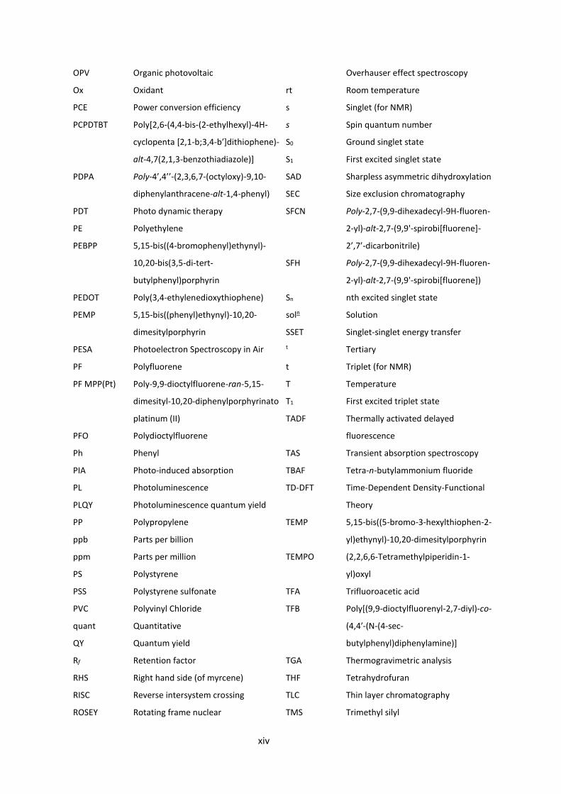
sector in some fashion. Table 1.1.1 shows some synthetic polymers that are common in
everyday life. It should be noted that each polymer may be produced in different forms,
depending on how it is synthesised and so may appear in different forms that are used for
different applications.
The characteristics of the polymer depend on the structure of the monomers, as well as its
macromolecular structure (molecular weight, degree of branching, 3D folded structure), and
its intermolecular and intramolecular interactions. Chemists control how differences in the
structure of the monomers will result in differences between polymers, by introducing
different atoms into the structure the material will clearly be different. The macromolecular
structure and intermolecular interactions however are not as easy to visualise.
Low density polyethylene and high density polyethylene (LDPE and HDPE) are synthesised
from the same monomer, ethylene. By controlling the reaction conditions during the free
radical polymerisation of ethylene, branching of the polymer chain as it grows can be
encouraged (catalyst free, initially formed primary radicals may more easily migrate to more
stable secondary and tertiary positions before reacting) or discouraged (Ziegler-Natta
3
catalysts for example stabilise the primary radicals on the chain ends and thereby promote
linear chain growth). A linear chain with few branch points may pack more efficiently together.
The macromolecular structure of HDPE therefore directly affects the intermolecular
interactions between polymer molecules, resulting in a material with high tensile strength.
LDPE by contrast has a lower tensile strength as its molecules do not pack together as
efficiently.
Table 1.1.1: Common polymers and their structures and uses.
Name Structure Properties and Uses Low Density Polyethylene (LDPE)
Flexible plastics – squeeze bottles, six-pack rings
High Density Polyethylene (HDPE)
Less flexible plastics – piping, plastic toys
Polypropylene (PP)
More thermal resistance than PE – auto parts, food storage
Polyvinyl Chloride (PVC)
Rigid form has weather resistance – windows, garden furniture. With plasticiser – wiring, rubber replacement
Polystyrene (PS)
Transparent, rigid and inexpensive – Petri dishes, CD cases
Nylon (generic term referring to any polyamide. Structure shown is nylon 6)
Bio and chemi-resistant but very flexible – clothing, toothbrushes
Teflon (Polytetrafluoroethylene)
Hydrophobic and non-reactive – non-stick pans, coating on hospital equipment
Kevlar
High tensile strength to weight ratio – armour, bicycle tyres
4
Polyvinyl chloride (PVC) is another polymer that is used for different applications depending
on how it is synthesised. Intermolecular interactions are changed in this case more commonly
through the addition of a plasticiser dopant into the material. After the polymer has been
synthesised, plasticisers such as derivatives of phthalic acid are added to increase desirable
properties such as heat or UV resistance, based on the material’s end use.
The majority of polymers produced commercially are synthesised by radical polymerisation of
alkenes. The polymer composition is dependant on the reaction conditions, as discussed
above, so may be changed based on the choice of initiator, pressure, temperature etc. This
type of polymerisation is the most widely used in terms of total amount of polymer created
(the most common synthetic polymers, PE, PVC and PS, are all made through this method).
More complex systems are difficult to realise with this method however. The control
necessary to form defined structures with multiple monomers, or to use monomers with
additional aromatic functionality, is realised with metal catalysed cross coupling
polymerisation reactions.
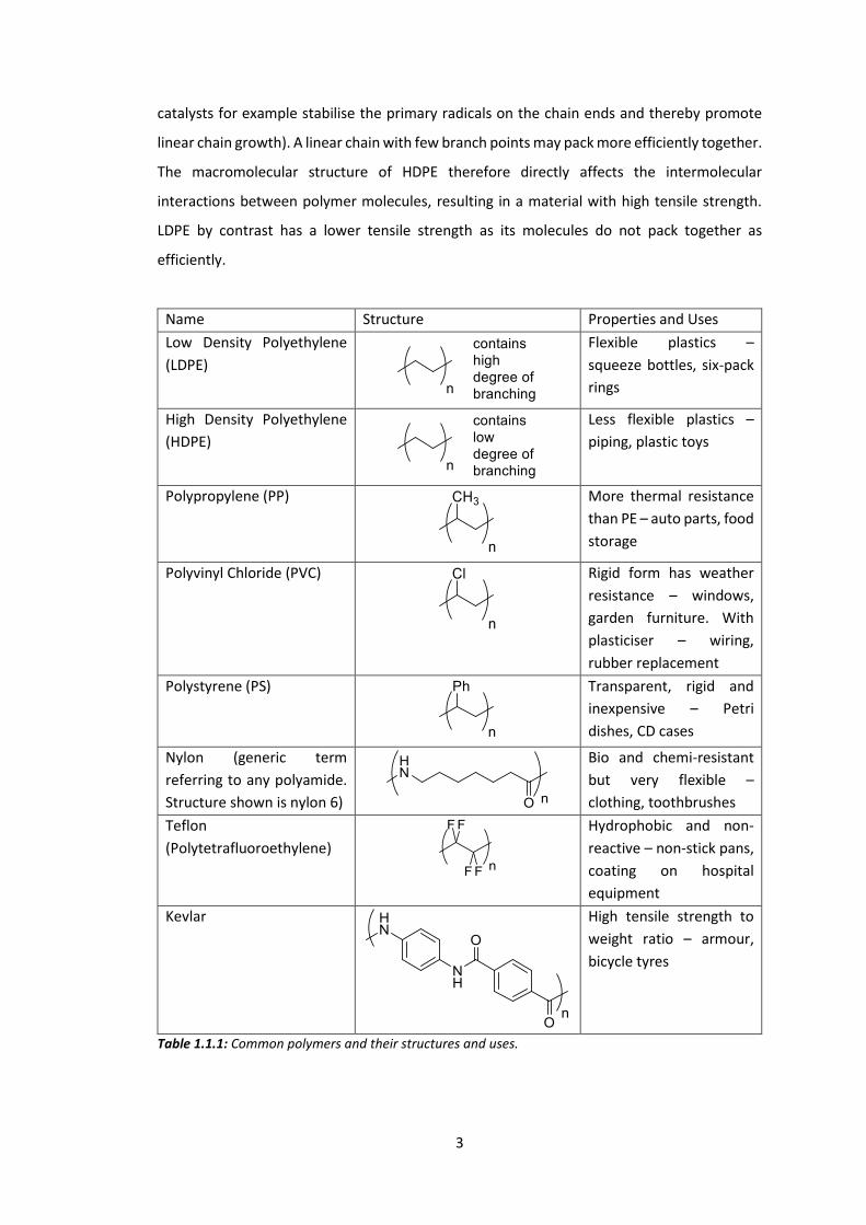
Name Reaction Primary uses Suzuki
Aryl-aryl bond formation. Polymerisations
Stille
Aryl-aryl bond formation. Polymerisations
Sonogashira
Terminal alkyne to aryl bond formation.
Heck
Alkene to aryl bond formation.
Buchwald-Hartwig
Formation of aryl amines or aryl ethers
Table 1.1.2: Cross coupling reactions used in this work. Ar – aromatic, R – H, aliphatic or aromatic.
The method of creating complex polymers made of several multifunctional monomers in this
work is through metal catalysed cross coupling polymerisation reaction. This work uses almost
exclusively the Suzuki reaction for polymerisations, although some work used the Stille
reaction. These are not the only cross coupling reactions available to polymer chemists
5
however, other types of this reaction were often used in the synthesis of monomers. Table
1.1.2 summarises these reactions, note that the reactions are meant as a guide only. There
are many exceptions to the aryl and alkyl groups, for example the Stille reaction is often
performed on alkenes.
Because of the conjugated nature of the polymers described in this work, the method of
polymerisation must be one in which a conjugated product is formed. This normally means
the coupling of aryl groups (alkynes and alkenes also give conjugated products, but are
employed less by semiconducting polymer chemists), which is why the Suzuki or Stille
reactions are utilised. A Negishi reaction is another viable alternative for polymerisations
using aryl zinc compounds, however this was never attempted for any synthesis herein.
The polymers described in this work are named according to IUPAC convention in the
experimental section, but are given alternative, acronym based names in the main text for
readability.1
6
1.2 Organic Semiconducting Devices
Semiconductors are an integral part of the modern world. Electronic devices contain billions
of transistors, light-emitting diodes (LEDs) are used for many lighting and display applications
and the solar energy industry relies on the light absorbing properties of semiconducting
materials in solar cells. Semiconductors have a conductivity between that of metals and
insulators, a result of their particular energy level structure. In the ground state, filled energy
levels in a valence band are separated in terms of energy by a band gap that is of comparable
energy to the device energy input to a conduction band of unfilled energy levels. An excited
electron in a conduction band may move through the semiconductor, as may a hole in the
valence band. An electron-hole pair is known as an exciton.
Silicon, germanium and compounds of gallium are the most commonly used materials for
semiconducting devices. They are tuned for use usually via doping with, for example, boron
or phosphorus compounds to create p and n-type semiconductors. This creates a material that
is either rich or poor in electron density and allows electrons or holes to move more freely
across the semiconductor. Blending p and n-type semiconductors together is the basis of
many types of semiconducting materials, as electrons in a valence band (VB) may be excited
into a conduction band (CB) and thus create partially filled energy levels and allow conduction.
The difference between the VB and CB is known as the band gap.
An alternative to inorganic metalloid systems is to use organic semiconductors. Organic
semiconductors are conjugated π-systems that are made from primarily carbon and hydrogen
with various amounts of oxygen, nitrogen and sulphur. Organic π-conjugated polymers and
their electronic properties have been of interest to polymer scientists for many years and in
recent years have seen significant advances.2 The band-gap of organic semiconductors is
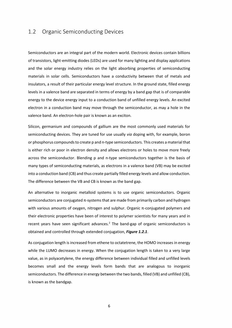
obtained and controlled through extended conjugation, Figure 1.2.1.
As conjugation length is increased from ethene to octatetrene, the HOMO increases in energy
while the LUMO decreases in energy. When the conjugation length is taken to a very large
value, as in polyacetylene, the energy difference between individual filled and unfilled levels
becomes small and the energy levels form bands that are analogous to inorganic
semiconductors. The difference in energy between the two bands, filled (VB) and unfilled (CB),
is known as the bandgap.
7
Figure 1.2.1: Energy levels of simple π-conjugated systems of increasing length. Green energy levels
represent non-populated, mainly antibonding orbitals and blue energy levels represent populated,
mainly bonding orbitals. Molecular orbitals shown on structures are lowest lying frontier orbitals.
The synthetic approach to the creation of these types of semiconductor imbue them with
various advantages over inorganic counterparts. Using organic molecules in this field has the
advantage of tunability by molecular modification. This allows for optoelectronic functions
and material properties to be minutely controlled as the molecular structure of these systems
is changed. Processability is also much larger; soluble organic polymers may be easily spin
coated or even printed onto devices with the result of much reduced processing costs of
manufacture. New physical properties of devices are also made available; as well as being light
in weight an organic polymer may be bent and twisted or made to be transparent, properties
that are challenging to realise in inorganic systems and desirable for versatile applications and
device durability.
Research in this area has resulted in the 2000 Nobel prize in chemistry being awarded to Alan
Heeger, Alan MacDiarmid and Hideki Shirakawa who initially reported the high conductivity
of iodine doped polyacetylene in 1977.3 The semiconducting ability of conjugated polymers
allows for several optoelectronic functions, including their incorporation into organic light
E VB
CB
butadiene octatetrene polyacetylene

8
emitting diodes (OLEDs) and organic photovoltaics (OPVs). A simple OLED device structure is
shown in Figure 1.2.2, in which a battery is joined through two electrode layers to a photon
emitting layer, the semiconducting polymer. This device structure is similar to one published
in 1990 by Holmes et al. that was among the first reported OLED devices.4
Figure 1.2.2: Device structure (top) and energy level diagram (bottom) of simple OLED device based on poly(1,4-
phenylene vinylene) (PPV). Absolute energy levels are estimates included to show relative relationships.
Electrons injected from the low work function cathode and holes injected from the high work
function anode are transferred to the semiconducting layer, where they meet and form an
exciton. The radiative decay of this exciton results in the emission of a photon with energy
equivalent to the band gap of PPV, 2.5 eV or 496 nm (5.2 eV – 2.7 eV). The anode and cathode
are chosen so that their wavefunctions match the LUMO (for the cathode) and HOMO (for the
anode) of the emissive polymer. At least one electrode must also fulfil the criteria of being
transparent, so as to allow photons created by the semiconductor to escape the device. In
9
most cases, indium tin oxide (ITO) is utilised as the anode. ITO is a transparent and processable
material with a convenient wavefunction energy of 4.8 eV.
OLEDs have seen the most commercial success of any organic semiconducting material
application, their uses include mobile phone screens, televisions and low energy lighting.5-6
Other uses that are not currently a large part of their respective markets, but may be in the
future, are photovoltaics (OPVs)7, field effect transistors (OFETs)8 and LASERs (OLASERs)9.
Some of these applications will be discussed briefly in terms of a generic semiconductor. As
the focus of most of this work, most time is spent on OLEDs.
For OLEDs, the semiconducting polymer layer will be comprised of an organic molecule that
exhibits strong light emission upon electrical excitation. The molecular design of the polymer
and the incorporation of various dopants can tune the frequency of emitted light and allows
for the development of red, green and blue emitters, necessary for the production of colour
displays. More recently there has been interest around near-infrared (NIR) emitters, which
may find uses as night-vision-readable displays or certain types of sensors.10
Figure 1.2.2 has already shown how a simple OLED may operate. Modern devices however
are normally more complex and contain additional layers that aid the device operation in
various ways. Figure 1.2.3 shows how the device in Figure 1.2.2 may be improved upon. This
device is based on a subsequent device reported by Holmes et al. but modified to show more
layers for the purposes of this introduction to OLED device structure.11
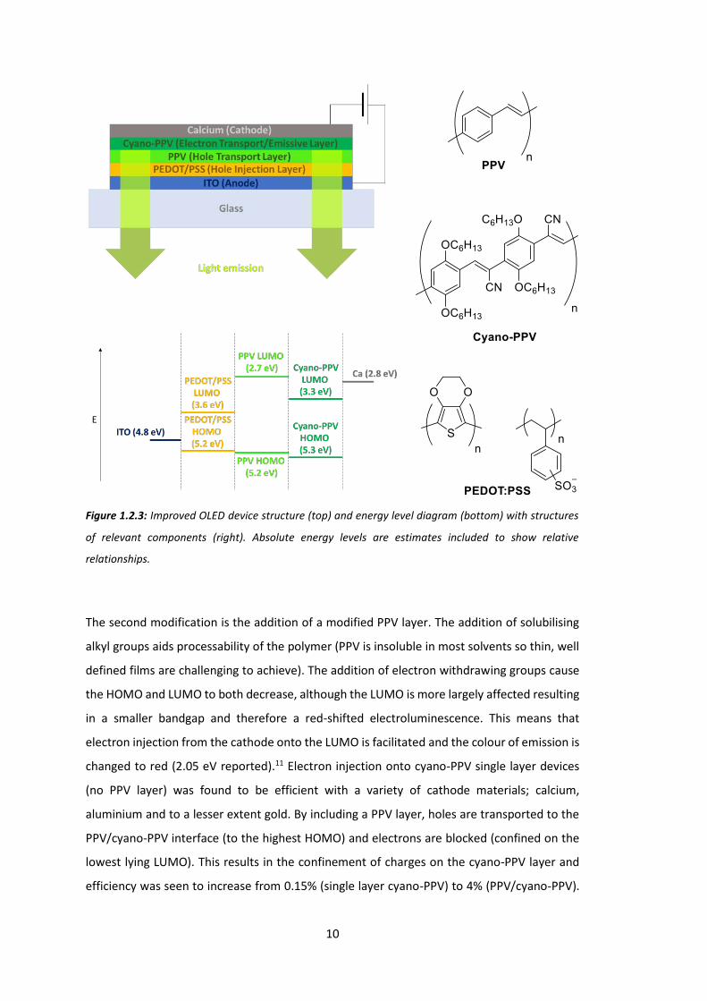
Two additional layers have been added into the device structure in Figure 1.2.3, a layer of
PEDOT:PSS and an additional, modified PPV layer. PEDOT:PSS is often added to the ITO anode
in fabricated devices. It forms a smooth layer that holes may be injected onto that has good
compatibility with other organic layers added subsequently. Like the anode, it is important
that this layer be transparent to allow light to escape the device.12-13
10
Figure 1.2.3: Improved OLED device structure (top) and energy level diagram (bottom) with structures
of relevant components (right). Absolute energy levels are estimates included to show relative
relationships.
The second modification is the addition of a modified PPV layer. The addition of solubilising
alkyl groups aids processability of the polymer (PPV is insoluble in most solvents so thin, well
defined films are challenging to achieve). The addition of electron withdrawing groups cause
the HOMO and LUMO to both decrease, although the LUMO is more largely affected resulting
in a smaller bandgap and therefore a red-shifted electroluminescence. This means that
electron injection from the cathode onto the LUMO is facilitated and the colour of emission is
changed to red (2.05 eV reported).11 Electron injection onto cyano-PPV single layer devices
(no PPV layer) was found to be efficient with a variety of cathode materials; calcium,
aluminium and to a lesser extent gold. By including a PPV layer, holes are transported to the
PPV/cyano-PPV interface (to the highest HOMO) and electrons are blocked (confined on the
lowest lying LUMO). This results in the confinement of charges on the cyano-PPV layer and
efficiency was seen to increase from 0.15% (single layer cyano-PPV) to 4% (PPV/cyano-PPV).

11
This shows how device structure influences the overall operation of the device, and how an
understanding of the characteristics of each layer leads to more efficient devices.
Other types of layers and materials are sometimes incorporated into OLED devices.14 By
blocking or transporting holes and/or electrons, materials scientists may intelligently design a
device to be more efficient than its predecessors. The work presented here is concerned
mostly with the modification of the semiconducting polymer however, rather than the device
as a whole.
The ability of chemists to modify existing structures in order to tune in desirable
characteristics is one of the greatest advantages of organic systems for semiconducting
applications. This advantage is not limited to OLEDs however, all organic semiconducting
devices share this benefit.
The basic structure of an OPV device is similar to an OLED. Figure 1.2.4 shows how Holmes et
al. used the same cyano-PPV polymer (blended with a related polymer, MEH-PPV) for light
absorbing applications that had been used for light emitting applications previously (Figure
1.2.3).15 Rather than injecting charge onto the semiconductor however, charge is created
when light is shone upon the semiconducting layer which is then separated into holes and
electrons and collected by the electrodes. The separation of charge is important for these
devices, so a common motif is a donor-acceptor blended structure. Hence a blend of two
polymers is used in Figure 1.2.4. An exciton is separated in this motif as the component parts,
an electron and a hole, are more stable on different parts of the system.
Figure 1.2.4: Device structure of OPV.15
12
In the case of OPVs, devices are usually created using a blend of semiconducting polymer as a
donor and a fullerene acceptor, although other accepting layers are possible (as in Figure
1.2.4). The donor absorbs light and the blended system as a whole creates a separation of
charges. This separation of charge may then result in a voltage across the system and
therefore the flow of electricity. In the last decade power conversion efficiencies (PCEs) of
single junction OPVs have been increased from less than 1% to over 9%.16
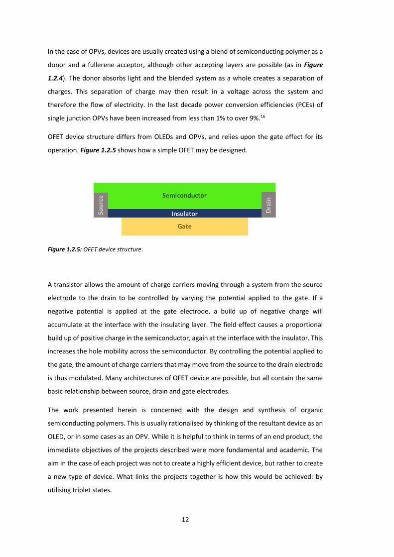
OFET device structure differs from OLEDs and OPVs, and relies upon the gate effect for its
operation. Figure 1.2.5 shows how a simple OFET may be designed.
Figure 1.2.5: OFET device structure.
A transistor allows the amount of charge carriers moving through a system from the source
electrode to the drain to be controlled by varying the potential applied to the gate. If a
negative potential is applied at the gate electrode, a build up of negative charge will
accumulate at the interface with the insulating layer. The field effect causes a proportional
build up of positive charge in the semiconductor, again at the interface with the insulator. This
increases the hole mobility across the semiconductor. By controlling the potential applied to
the gate, the amount of charge carriers that may move from the source to the drain electrode
is thus modulated. Many architectures of OFET device are possible, but all contain the same
basic relationship between source, drain and gate electrodes.
The work presented herein is concerned with the design and synthesis of organic
semiconducting polymers. This is usually rationalised by thinking of the resultant device as an
OLED, or in some cases as an OPV. While it is helpful to think in terms of an end product, the
immediate objectives of the projects described were more fundamental and academic. The
aim in the case of each project was not to create a highly efficient device, but rather to create
a new type of device. What links the projects together is how this would be achieved: by
utilising triplet states.

13
1.3 Triplet states in Organic Semiconductors
The HOMO of an organic semiconductor in its ground state is populated by 2 paired electrons
that are necessarily of equal and opposite spins due to the Pauli exclusion principle. When
one electron is promoted to the LUMO to form an exciton, the ground and excited electrons
need not be paired, as they now occupy separate orbitals. This leads to 4 possible
configurations of the electrons relative to each other, 3 in which the spins are parallel and 1
in which they are antiparallel. These describe the exciton in triplet and singlet states
respectively. Figure 1.3.1 shows graphically how this occurs.
Figure 1.3.1: Singlet (left) and triplet (right) vector representations of an electronically excited two
electron system. The singlet system has a spin quantum number (S) of 0 and a spin component of the
system (Ms, found by combining the spin components of the electrons in the system) of 0. The triplet
systems all have S = 1 (lying along the black vector) and may have Ms = 1, 0 or -1.
In the singlet case, the two spin momenta of the electrons in the system are antiparallel and
cancel each other out, resulting in a system with an overall spin quantum number of 0. There
is only 1 possible way of achieving this result, when the vectors lie in opposite directions.
There are 3 ways of forming a triplet state however, which has an overall spin quantum
number (s) of 1 and may have a spin component (Ms) of 1, 0 or -1. While the vectors of the
individual electrons of the triplet states point in different directions, the angle between them

14
is always the same in each case which leads to the constant spin quantum number of 1 for all
triplet states.
Figure 1.3.2 shows a Jablonski diagram in which a singlet exciton decays to the lowest excited
singlet state S1 through vibrational relaxation and then through fluorescence to its ground
state S0. An exciton in its singlet state may decay radiatively, losing a quanta of energy through
the emission of a photon. This is possible only because the electrons are orientated to already
be able to occupy the same orbital. This process is therefore fast.
Figure 1.3.2: Jablonski diagram showing first excited singlet and triplet states for a generic system and
their decay pathways to the ground state. Processes shown are fluorescence (blue), phosphorescence
(red), intersystem crossing (purple), internal conversion (orange) and vibrational relaxation within an
electronic state (grey).
The pathway of decay for an exciton in a triplet state is a much slower process. According to
Hund’s rule, the first excited triplet state (T1) for a system will be lower in energy than the first
excited singlet (S1) as this maximises the multiplicity of the system (2S+1 where S is the total
spin angular momentum for all electrons). This is important as it means that the process of an
excited electron undergoing intersystem crossing from S1→T1 is more favoured compared to
the reverse (reverse intersystem crossing, RISC, S1←T1), as a more stable system is formed.
Radiative decay from T1→S0 is known as phosphorescence. This is a spin disallowed process,
as the electrons in the excited and ground orbitals of the exciton do not have antiparallel spins
and so may not occupy the same orbital unless the spin of one is changed. This process is slow
15
in normal systems and radiative decay from T1 is not observed unless a part of the system
exhibits strong spin orbit coupling that allows for an excited electron to change spin. For this
reason, the formation of triplet excitons is often associated with a loss of efficiency in a device,
as energy stored in these states is generally lost through non-radiative processes.
In a fluorescent organic material suitable for an OLED device such as PPV and its derivatives,
an excited singlet exciton may decay to its ground state and emit a photon with energy
equivalent to the band gap of the material. Spin statistics show that injection of holes from
the anode and electrons from the cathode will result in the creation of exited states where
25% are singlets and 75% are triplets. Fluorescent based OLEDs therefore may only have a
maximum internal quantum efficiency of 25%, since 75% of excited states do not decay
radiatively. The development of phosphorescent materials containing heavy metals has
allowed the development of high efficiency OLEDs that may harvest triplet excitons. Triplet
states do not typically decay radiatively to a singlet ground state because this would result in
an overall change in spin, s, which is a forbidden transition in terms of quantum mechanics.
Heavy metals such as platinum (II) or iridium (III) are large enough to exhibit spin-orbit
coupling, distorting the system and allowing radiative transitions where ΔS ≠ 0. Therefore, by
doping a blue emitting OLED material with a blue absorbing phosphorescent material, energy
may be transferred from a fluorescent material with low electroluminescent efficiency to a
phosphorescent material with high electroluminescent efficiency via FRET.
Figure 1.3.3 shows an energy level cartoon in which an OLED doped with a heavy metal
containing phosphorescent material, in this case a porphyrin, transfers energy from polymer
backbone to dopant which in turn emits light. The red arrows from S0 to S1 and S0 to T1 of the
polymer represent electrical excitation and the formation of a singlet exciton (25% of injected
charge) and a triplet exciton (75%). In a standard system the singlet exciton may then decay
back to the ground state with emission of light equivalent in energy to the S0→S1 gap; the
bandgap of the polymer. If either exciton is sufficiently close in space to (and has the required
mobility to reach) the dopant molecule, triplet-triplet energy transfer (TTET) and singlet-
singlet energy transfer (SSET) may occur (orange arrows) in which an excited exciton from the
polymer transfers to an excited state on the dopant (singlet to singlet and triplet to triplet, ΔS
= 0). Providing the S1 or T1 level of the dopant is below that of the polymer, this will be a
favourable transition. Since the dopant contains a heavy metal and therefore exhibits
substantial spin-orbit coupling, intersystem crossing (ISC) may rapidly place the singlet exciton
into a triplet exited state on the dopant, T1, shown as a purple arrow. Phosphorescence,
shown as a red arrow, emits a photon with energy equivalent to the S0 to T1 gap of the dopant,

16
again facilitated by the spin orbit coupling of the heavy metal. Note that without the
phosphorescent dopant, only the initially formed singlet would be able to emit light via
fluorescence. All triplet excitons formed would not contribute to the emission of light but
would rather decay non-radiatively which limits the internal quantum efficiency of the system
to 25%.
Figure 1.3.3: Jablonski type diagram showing possible radiative decay pathway of OLED doped with
phosphorescent material (porphyrin).
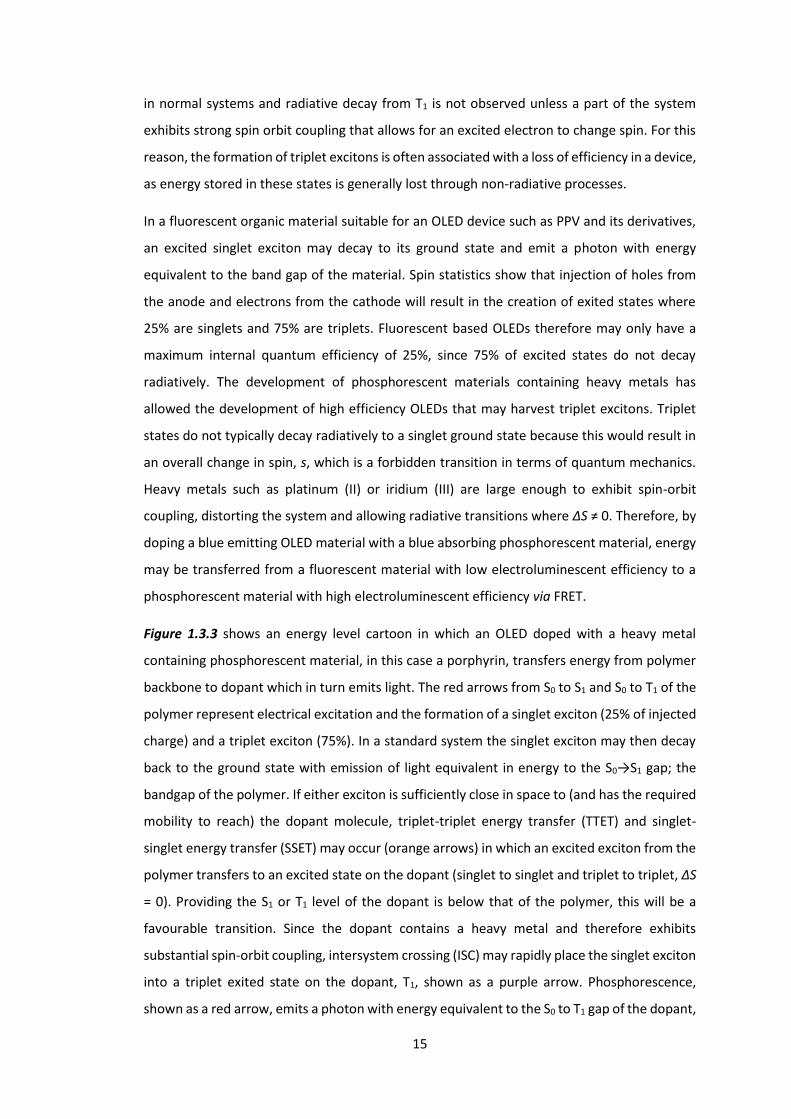
OPVs can also benefit from phosphorescent dopants. Figure 1.3.4 shows an OPV device in
which a triplet excited state is formed from low energy light which is then transferred to T1 of
the polymer, and subsequently undergoes triplet-triplet annihilation (TTA) upconversion with
a second triplet excited state to form a higher energy excited singlet state. Low energy light is
absorbed by the dopant and promotes an electron to the S1 excited state (red arrow). Light
absorption always results in a singlet state, because it is created from the promotion of a
paired electron rather than by charge injection. Note that this is a relatively low lying excited
state, the S1 of the polymer backbone being much higher in energy. This means that the low
energy light that was absorbed by the dopant would not be electronically absorbed by the
polymer. Intersystem crossing (purple arrow) to a more stable T1 state of the porphyrin is
facilitated by the heavy metal exhibiting spin orbit coupling. The excited electron is then
transferred to the main polymer backbone via internal conversion (intramolecular process) or
TTET (intermolecular process) (orange arrow). TTA may occur (dark blue arrow) if two triplet
excited states are close to each other, resulting in one ground state and one high energy
(compared to the initially absorbed energy) singlet state.17-18
17
Figure 1.3.4: Possible utilisation of triplet states for OPV applications.
One advantage of absorbing low energy light is that more of the solar spectrum becomes
available for absorption, Figure 1.3.5. As in the case of the OLED device, the heavy metal
complexed dopant singlet excited state may decay to the lower lying triplet state by ISC
(purple arrow) promoted by spin-orbit coupling. TTET to T1 of the polymer, similar in energy
to T1 of the dopant, transfers the excited state onto the polymer backbone (orange arrow). If
two T1 excited states are in close enough proximity on the polymer backbone, upconversion
may occur (dark blue arrows).19 Upconversion results in one excited state decaying to the
ground S0 state and another being promoted to a higher energy state, in this case S1. The
energy of the excited S1 state may then be harvested by the solar device through charge
separation. In this way it becomes possible to utilise light of low energy to create a voltage of
high energy. These wavelengths of light would otherwise have not been usefully absorbed.
18
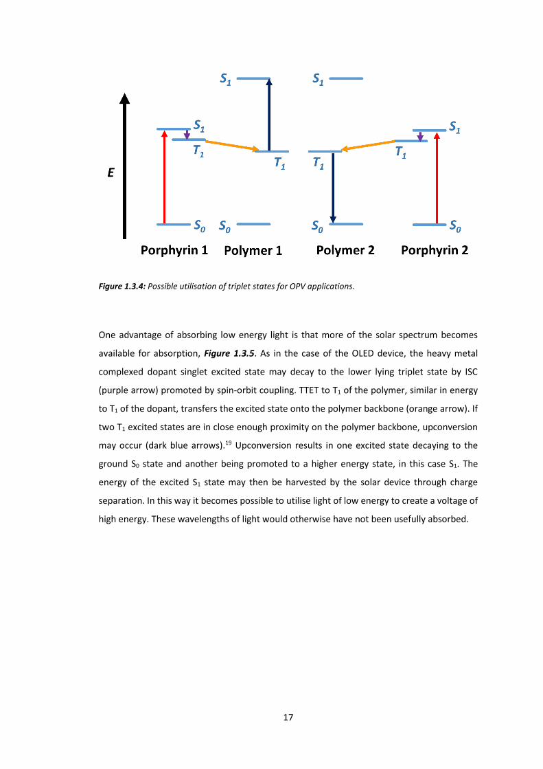
Figure 1.3.5: Solar spectrum annotated with band gap energy, shown as a red line, of poly[2,6-(4,4-bis-
(2-ethylhexyl)-4H-cyclopenta[2,1-b;3,4-b]-dithiophene)-alt-4,7-(2,1,3-benzothiadiazole)] (PCPDTBT) 1.
Data obtained from the American Society for Testing and Materials (ASTM).
Figure 1.3.5 shows the solar spectrum. This represents all the available energy that a solar cell
may absorb, with higher energy photons on the left with lower wavelengths and lower energy
photons on the right with higher wavelengths. Also shown is PCPDTBT, an OPV
semiconducting polymer that has been shown to have up to 5.5% PCE with a bandgap of 1.46
eV (850 nm). PCPDTBT is one of the most successful OPV semiconducting polymers.20 This
bandgap means that photons with wavelength of ≤850 nm (≥1.46 eV) may be electronically
absorbed by the polymer, creating an excited state that may produce a voltage equivalent to
that bandgap (=1.46 eV). The red line in Figure 1.3.5 shows where the bandgap of PCPDTBT
lies in relation to the solar spectrum. PCPDTBT can successfully absorb photons that have a
wavelength lower than 850 nm, all those to the left of the red line. The lower energy photons
that appear to the right of the red line do not have enough energy to excite the polymer and
are therefore not electronically absorbed. If the bandgap is decreased, more photons will be
absorbed, but since the bandgap is smaller, the voltage output will also be smaller. This trade-
off between amount of solar spectrum absorbed and voltage output leads to a theoretical
maximum efficiency of a solar cell, known as the Shockley–Queisser limit. The limit describes
PCPDTBT

19
the maximum possible PCE for a single junction solar cell with an ideal bandgap of 1.34 eV as
33.7%.21
One way to increase this limit is by incorporating heavy metal complexes that are capable of
upconversion. By adding a dopant as in Figure 1.3.4, the bandgap of the polymer may remain
high while the dopant absorbs low energy photons and transfers that energy onto the
polymer. Upconversion has previously been shown to work for blends of materials where a
semiconducting polymer is simply blended with a heavy metal complexed molecule with the
required energy levels.19, 22-23 There are problems to overcome with blends however. The
materials tend to be fairly crystalline which results in aggregation and phase separation; this
means an exciton is less likely to reach a phase boundary so charge separation does not occur.
To overcome the problems associated with blends, this work in part considers covalently
incorporating the dopant directly into a polymer backbone. While synthetically more
challenging, having the dopant covalently bonded to the polymer will both increase the rate
of energy transfer and reduce loss processes by maintaining the absorbing and emitting
moieties at fixed distances. Figure 1.3.6 shows how energy transfer can occur over a shorter
distance by covalently linking the dopant within the polymer backbone. Another advantage is
an increase in solubility of the whole system, meaning the whole film could potentially be spin
coated or printed, much reducing the cost of production on a commercial scale while
simultaneously lessening aggregation effects.
Figure 1.3.6: Blend of polymer (grey) and dopant (yellow) (left) vs dopant covalently linked into polymer
(right). Red and blue arrows represent energy transfer.
20
1.4 Porphyrins
One promising group of materials to be used as phosphorescent dopants in OPVs and OLEDs
are porphyrins.24 In most biological light absorbing systems, solar energy is absorbed and the
energy efficiently transported and converted to chemical energy by a porphyrin containing
chromophore, most commonly chloropyhll.25 Good electrical properties, arising from the
porphyrin π system, have led to a wide range of applications such as dye-sensitised solar cells
(DSS) (12.3% efficiency measured)26, bioimaging27 and photodynamic therapy (PDT)28.
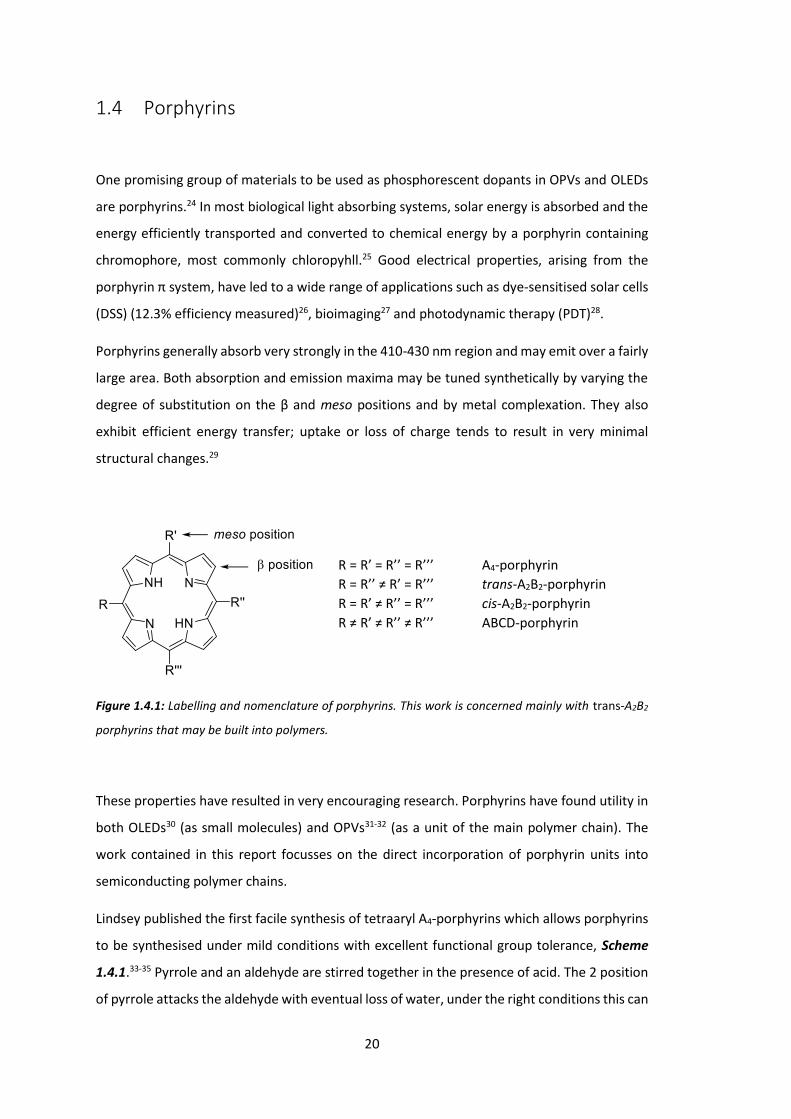
Porphyrins generally absorb very strongly in the 410-430 nm region and may emit over a fairly
large area. Both absorption and emission maxima may be tuned synthetically by varying the
degree of substitution on the β and meso positions and by metal complexation. They also
exhibit efficient energy transfer; uptake or loss of charge tends to result in very minimal
structural changes.29
Figure 1.4.1: Labelling and nomenclature of porphyrins. This work is concerned mainly with trans-A2B2
porphyrins that may be built into polymers.
These properties have resulted in very encouraging research. Porphyrins have found utility in
both OLEDs30 (as small molecules) and OPVs31-32 (as a unit of the main polymer chain). The
work contained in this report focusses on the direct incorporation of porphyrin units into
semiconducting polymer chains.
Lindsey published the first facile synthesis of tetraaryl A4-porphyrins which allows porphyrins
to be synthesised under mild conditions with excellent functional group tolerance, Scheme
1.4.1.33-35 Pyrrole and an aldehyde are stirred together in the presence of acid. The 2 position
of pyrrole attacks the aldehyde with eventual loss of water, under the right conditions this can
R = R’ = R’’ = R’’’ A4-porphyrin R = R’’ ≠ R’ = R’’’ trans-A2B2-porphyrin R = R’ ≠ R’’ = R’’’ cis-A2B2-porphyrin R ≠ R’ ≠ R’’ ≠ R’’’ ABCD-porphyrin

21
result in the formation of a porphyrinogen ring, 1.4.1, which may then be oxidised to a
porphyrin 1.4.2. The synthesis becomes more complicated when trans A2B2-porphyrins 1.4.4
are desired, the general strategy being to react a dipyrromethane 1.4.3 with an aldehyde in
an analogous reaction to A4-porphyrin synthesis again using mild conditions, and then to
further derivatise once the porphyrin framework has been built.
Scheme 1.4.1: General syntheses of A4- (top) and trans A2B2-porphyrins (bottom).
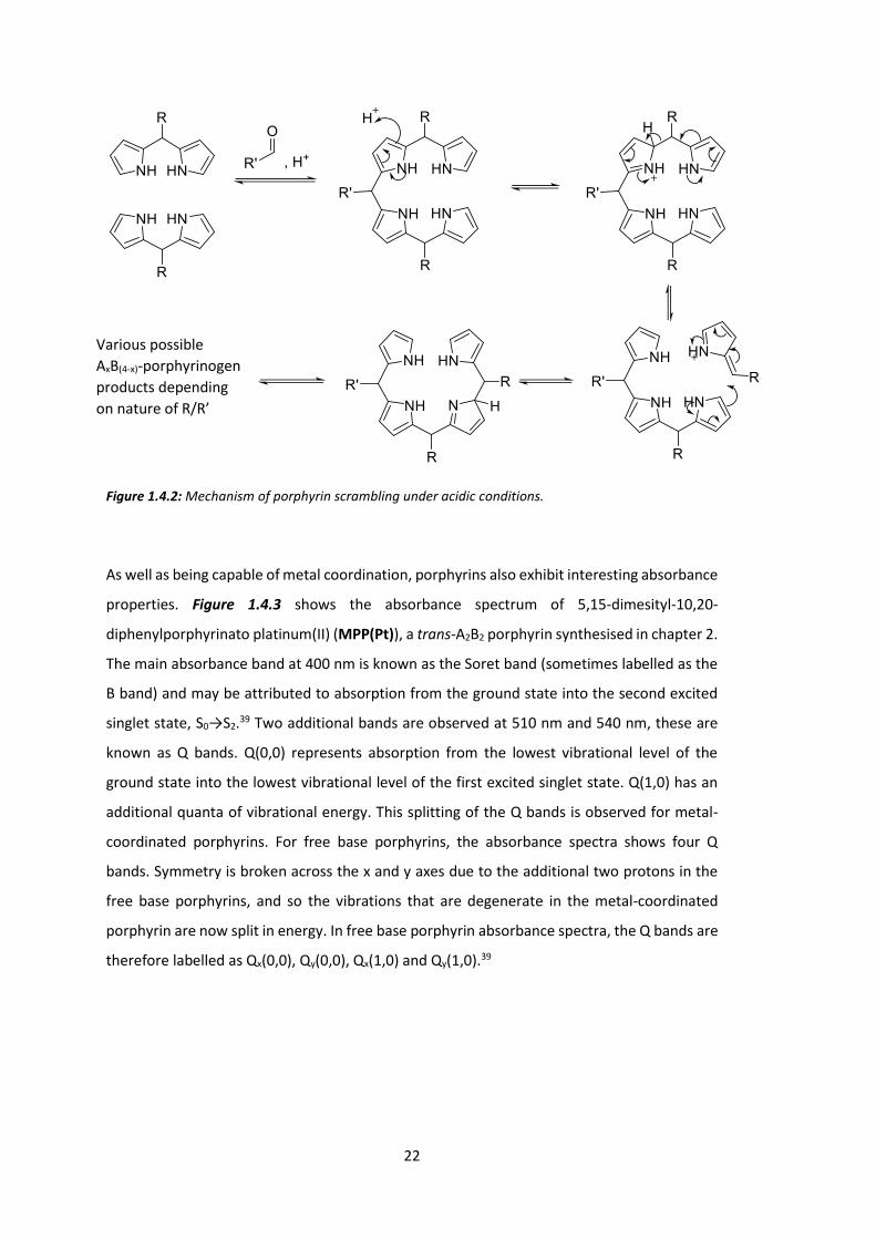
One problem with Lindsey’s synthesis of A2B2-porphyrins is the possibility of scrambling.
Under the acidic conditions necessary for reaction, multiple AxB(4-x)-porphyrin products may
be formed as shown in Figure 1.4.2.36-37
While it is relatively easy to separate the desired porphyrin from other reaction side products
(generally, small molecules are removed by washing the sparingly soluble porphyrin and larger
oligomers are removed by short silica plug), it is very difficult to separate a mixture of similar
porphyrins. Similar solubilities and polarities (Rf values) cause difficulties in both
chromatography and recrystallisation and as a result scrambling often realistically equates to
a failed reaction.38
1.4.1 1.4.2
1.4.3
1.4.4
22
Figure 1.4.2: Mechanism of porphyrin scrambling under acidic conditions.
As well as being capable of metal coordination, porphyrins also exhibit interesting absorbance
properties. Figure 1.4.3 shows the absorbance spectrum of 5,15-dimesityl-10,20-
diphenylporphyrinato platinum(II) (MPP(Pt)), a trans-A2B2 porphyrin synthesised in chapter 2.
The main absorbance band at 400 nm is known as the Soret band (sometimes labelled as the
B band) and may be attributed to absorption from the ground state into the second excited
singlet state, S0→S2.39 Two additional bands are observed at 510 nm and 540 nm, these are
known as Q bands. Q(0,0) represents absorption from the lowest vibrational level of the
ground state into the lowest vibrational level of the first excited singlet state. Q(1,0) has an
additional quanta of vibrational energy. This splitting of the Q bands is observed for metal-
coordinated porphyrins. For free base porphyrins, the absorbance spectra shows four Q
bands. Symmetry is broken across the x and y axes due to the additional two protons in the
free base porphyrins, and so the vibrations that are degenerate in the metal-coordinated
porphyrin are now split in energy. In free base porphyrin absorbance spectra, the Q bands are
therefore labelled as Qx(0,0), Qy(0,0), Qx(1,0) and Qy(1,0).39
Various possible AxB(4-x)-porphyrinogen products depending on nature of R/R’

23
350 400 450 500 550 6000.0
0.2
0.4
0.6
0.8
1.0
Figure 1.4.3: Normalised UV-Vis absorbance spectrum of trans-A2B2 porphyrin MPP(Pt).
The Q bands of porphyrins are an important low energy absorption and emission pathway.
Absorbance and emission of low energy red light as well as the strong spin-orbit coupling of
platinum complexed porphyrins are useful properties that have been the basis of the
subsequent two chapters in this body of work.
Wavelength / nm
Nor
mal
ised
Abs
orpt
ion
Soret
Q(0,0) Q(1,0)
24
Chapter 2: Phosphorescent Polymers:
Incorporating a Covalently Bound
Porphyrin in Polymers
2.1 Introduction
This chapter will deal with everything pertaining to the first porphyrin synthesised in this body
of work; 5,15-dimesityl-10,20-diphenylporphyrinato platinum(II) (MPP(Pt)). MPP(Pt) is an
A2B2 porphyrin-platinum complex with a strong spin orbit coupling due to its heavy metal
centre. This results in a metal-complexed molecule that radiatively decays primarily through
phosphorescence (T1 → S0, 1.83 eV, 678 nm). Absorbance is observed at 405 nm and 510 nm
through the Soret and Q bands respectively. Our aims relating to the work presented in this
chapter were to covalently incorporate MPP(Pt) into varying host polymers in order to
enhance, optimise and/or change the performance of the porphyrin.
Phosphorescent emitters are of interest for application in OLEDs, as 100% internal quantum
efficiency is possible.40 Porphyrins have been used in this context as a blended system where
a phosphorescent porphyrin is blended with a polymeric host material. The first blends of
semiconducting materials and platinum complexes were reported in 1998.41 Since then many
such systems have been reported. Blends have inherent disadvantages however; dopant
aggregation and phase separation are common causes of increased phosphorescent
quenching.42-43 With increased synthetic effort, the phosphorescent dopant may be covalently
bound to the host backbone, which has been shown to mitigate these disadvantages.44-45 Pt(II)
porphyrins have been covalently bound to polymeric systems before, most commonly as
pendant groups into MEH-PPV to create deep-red emitting OLEDS for application in
biomedical, security and communication industries.46-53
Incorporating the porphyrin directly into the polymer backbone is less studied however.54 Cao
et al. have incorporated a porphyrin into polymers via the β-pyyrolic positions, Figure 2.1.1.55-
56

25
Figure 2.1.1: Polyfluorene with covalently bound porphyrin through β-positions.55-56
Xiang et al. have synthesised a meso incorporated porphyrin-polymer complex, but prepared
the polymer via a less controlled Yamamoto reaction and have only reported the properties
of the polymer in terms of oxygen sensing, Figure 2.1.2.
Figure 2.1.2: Meso linked porphyrin-polyfluorene complex.
Incorporation of a porphyrin into any system is normally done to promote or utilise triplet
formation. For the case of OLEDs, porphyrins are incorporated in order to utilise triplets via
phosphorescence. Our first aim was therefore to synthesise a polymer that could utilise any
triplet excitons formed when used as an OLED.
PFO is a well-studied and highly luminescent blue-emitting polymer. It has been used for many
applications (OLED, OPV, OFET, biosensors)57-60 and may be tuned to emit lower energy light
26
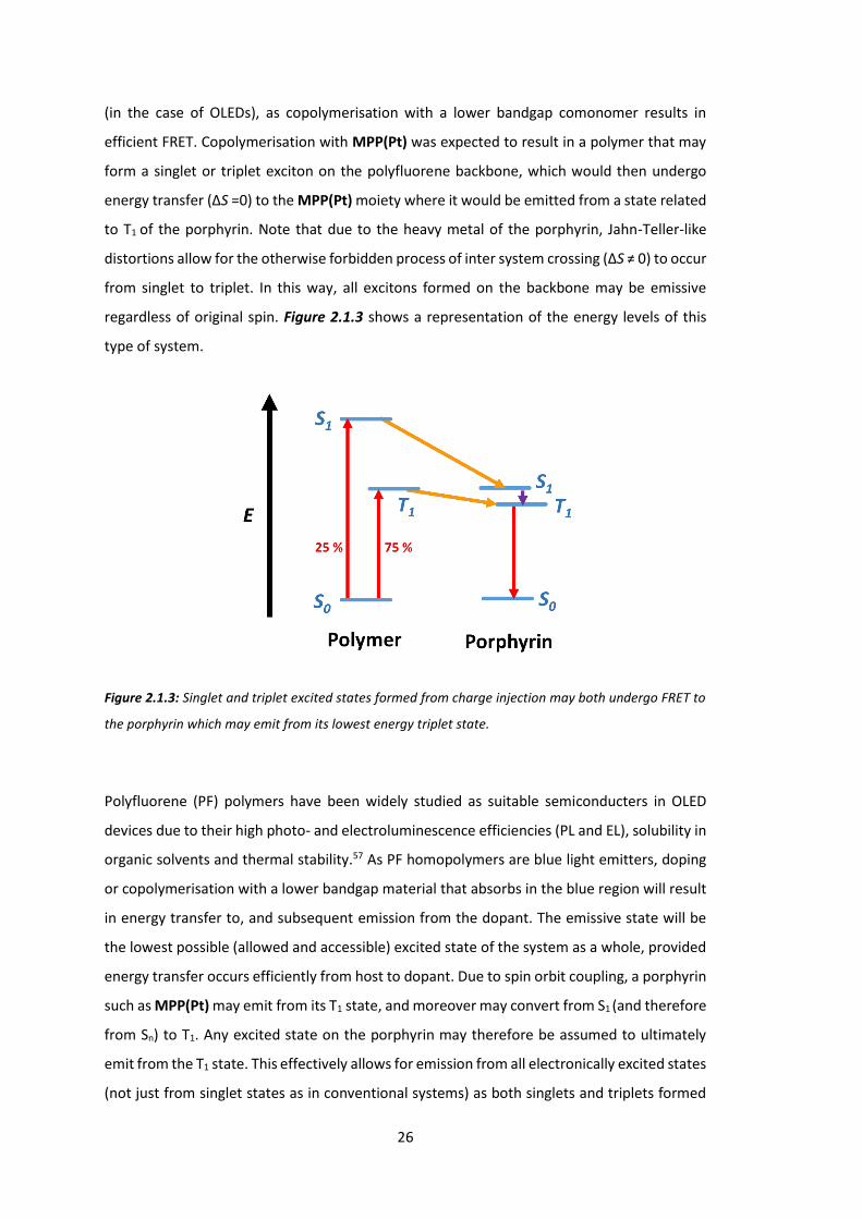
(in the case of OLEDs), as copolymerisation with a lower bandgap comonomer results in
efficient FRET. Copolymerisation with MPP(Pt) was expected to result in a polymer that may
form a singlet or triplet exciton on the polyfluorene backbone, which would then undergo
energy transfer (ΔS =0) to the MPP(Pt) moiety where it would be emitted from a state related
to T1 of the porphyrin. Note that due to the heavy metal of the porphyrin, Jahn-Teller-like
distortions allow for the otherwise forbidden process of inter system crossing (ΔS ≠ 0) to occur
from singlet to triplet. In this way, all excitons formed on the backbone may be emissive
regardless of original spin. Figure 2.1.3 shows a representation of the energy levels of this
type of system.
Figure 2.1.3: Singlet and triplet excited states formed from charge injection may both undergo FRET to
the porphyrin which may emit from its lowest energy triplet state.
Polyfluorene (PF) polymers have been widely studied as suitable semiconducters in OLED
devices due to their high photo- and electroluminescence efficiencies (PL and EL), solubility in
organic solvents and thermal stability.57 As PF homopolymers are blue light emitters, doping
or copolymerisation with a lower bandgap material that absorbs in the blue region will result
in energy transfer to, and subsequent emission from the dopant. The emissive state will be
the lowest possible (allowed and accessible) excited state of the system as a whole, provided
energy transfer occurs efficiently from host to dopant. Due to spin orbit coupling, a porphyrin
such as MPP(Pt) may emit from its T1 state, and moreover may convert from S1 (and therefore
from Sn) to T1. Any excited state on the porphyrin may therefore be assumed to ultimately
emit from the T1 state. This effectively allows for emission from all electronically excited states
(not just from singlet states as in conventional systems) as both singlets and triplets formed

27
on the backbone are eventually emitted from T1 of the porphyrin. This potentially boosts the
efficiency of an OLED system from a maximum of 25% (only singlets emit) to 100% (all initially
formed states may eventually result in emission).
Two publications have resulted from work around this porphyrin. Each of the two main
sections of this chapter will outline the design, synthesis and properties of a series of MPP(Pt)
containing polymers. Each section deals with the results from separate published bodies of
work that may be found in the appendix.61-62

28
2.2 A Platinum Containing Polyfluorene for Phosphorescent
Emission: PF MPP(Pt)
Poly-9,9-dioctylfluorene-ran-5,15-dimesityl-10,20-diphenyl porphyrin(Pt) (PF MPP(Pt)) is a
polyfluorene based polymer with a red/NIR emitting porphyrin incorporated into the
backbone in various weight percentages; MPP(Pt).
The PF backbone was formed by Suzuki cross coupling reaction of dibromo and diboronic ester
fluorenes 2.2.1 and 2.2.2 with MPP(Pt) added in various ratios so as to form 5 separate
polymers with weight percentages (w/w) of incorporated porphyrin; 0.0, 0.5, 1.0, 2.0 and 5.0.
Figure 2.2.1 summarises the reterosynthesis.
Figure 2.2.1: Reterosynthesis of PF MPP(Pt) to Suzuki polymerisation monomers.
2.2.1
2.2.2
MPP(Pt)
PF MPP(Pt)
29
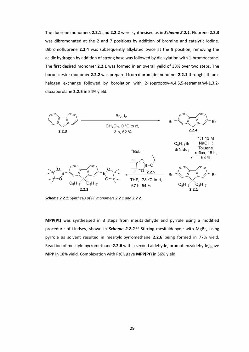
The fluorene monomers 2.2.1 and 2.2.2 were synthesised as in Scheme 2.2.1. Fluorene 2.2.3
was dibromonated at the 2 and 7 positions by addition of bromine and catalytic iodine.
Dibromofluorene 2.2.4 was subsequently alkylated twice at the 9 position; removing the
acidic hydrogen by addition of strong base was followed by dialkylation with 1-bromooctane.
The first desired monomer 2.2.1 was formed in an overall yeild of 33% over two steps. The
boronic ester monomer 2.2.2 was prepared from dibromide monomer 2.2.1 through lithium-
halogen exchange followed by borolation with 2-isopropoxy-4,4,5,5-tetramethyl-1,3,2-
dioxaborolane 2.2.5 in 54% yield.
Scheme 2.2.1: Synthesis of PF monomers 2.2.1 and 2.2.2.
MPP(Pt) was synthesised in 3 steps from mesitaldehyde and pyrrole using a modified
procedure of Lindsey, shown in Scheme 2.2.2.63 Stirring mesitaldehyde with MgBr2 using
pyrrole as solvent resulted in mesityldipyrromethane 2.2.6 being formed in 77% yield.
Reaction of mesityldipyrromethane 2.2.6 with a second aldehyde, bromobenzaldehyde, gave
MPP in 18% yield. Complexation with PtCl2 gave MPP(Pt) in 56% yield.
2.2.2
2.2.5
2.2.1
2.2.4 2.2.3

30
Scheme 2.2.2: Synthesis of MPP(Pt).
Suzuki polymerisation of the monomers was realised using Pd(OAc)2 with PPh3 as catalyst in
the presence of Aliquat 336 and base, Scheme 2.2.3. PF-MPP(Pt) was prepared with MPP(Pt)
in several weight percentages (w/w), controlled by varying the ratio of the monomers. The
amount of diboronic ester fluorene 2.2.2 was always constant while the ratio of dibromo
fluorene 2.2.1 and MPP(Pt) was varied to control the w/w of porphyrin in the final polymer.
MPP(Pt) was incorporated with w/w of 0.5%, 1.0%, 2.0% and 5.0% into PF MPP(Pt), giving a
range of products that were analysed together (P1, P2, P3 and P4 respectively, 0% is labelled
as PFO). The novel polymers were isolated as dark red solids and were purified by Soxhlet
extraction using acetone, hexane and finally chloroform. Gel permeation chromatography
(GPC) of the polymers showed a weight average molecular weight (Mw) of 12.0 to 23.0 kDa
with PDIs of 1.4 to 1.9 (Table 2.2.1).
MPP
MPP(Pt)
2.2.6

31
Scheme 2.2.3: Suzuki polymerisation to form PF MPP(Pt). The molar ratio of 2.2.2 to both 2.2.1 and
MPP(Pt) combined was 1:1, the ratio of MPP(Pt) to 2.2.1 was varied to create the 5 polymers.
Table 2.2.1: Synthetic results of polymerisation. a) Determined by reaction stoichiometery, b)
Determined by 1H NMR c) Determined by GPC using PhCl eluent.
The percentage incorporation of MPP(Pt) in each of the polymers was measured by 1H NMR.
Figure 2.2.2 shows how the ratio of pophyrin peaks to PFO peaks changes with increasing
porphyrin incorporation. The percentage incorporation of MPP(Pt) increases with increased
porphyrin feed ratio, and does so in a manner concurrent with the feed ratios. The estimated
incorporation values are shown in Table 2.2.1 and are based on the ratio between the alkyl
Polymer
w/w porphyrin /%
Mn / kDac
Mw / kDac
PDIc Feed Ratio a Incorporation ratio b
PFO 0.0 0.0 8.7 12 1.4
P1 0.5 0.2 8.0 15 1.8
P2 1.0 0.3 11 20 1.8
P3 2.0 0.9 11 17 1.6
P4 5.0 2.2 12 23 1.9
2.2.1 + 2.2.2
+ MPP(Pt)
PF MPP(Pt)
MPP(Pt)
2.2.1
2.2.2

32
protons closest to fluorene and the most downfield pyrrolic proton peaks, these being the
most isolated. This shows good evidence that the polymers are as expected relative to each
other and represent a good range of porphyrin incorporation. The values are lower than the
corresponding feed ratio; low incorporation to feed ratios have been shown before on similar
systems.64 It is thought that this discrepancy may be primarily a result of errors associated
with analysis of the NMR spectrum (polymers give broader, less defined peaks that are more
prone to overlapping with other nearby peaks), rather than lower than expected porphyrin
incorporation, due to the good solubility of MPP(Pt) in toluene.
By comparing the MPP(Pt) peaks in the polymers to monomeric MPP(Pt) and MPP, the peaks
may be tentatively identified in Figure 2.2.2. The four protons a-d come at 8.1, 8.4, 8.9 and
9.1 ppm respectively and are visualised as the intensity of the aromatic region is increased. All
four shifts are further downfield than MPP(Pt) as a monomer. Proton e is expected to be under
the much larger PFO peaks. The furthest downfield peaks (8.9 and 9.1 ppm) have been
assigned as c or d and the remaining peaks at 8.1 and 8.4 ppm have been assigned as a or b.
These assignments are based on the ordering of peaks of previous compounds
(heteroaromatic protons were further downfield than aromatic in all previous MPP
compounds). As the level of porphyrin incorporation into the polymer is increased from 0.5%
to 5.0%, the relative intensities of the proton peaks increases, qualitatively showing that the
four porphyrin containing polymers have a good range of w/w.

33
Figure 2.2.2: H1 NMR spectra of PF-MPP(Pt) containing 0.5% (P1, purple, top), 1.0% (P2, cyan, second
from top), 2.0% (P3, green, second from bottom) and 5.0% (P4, maroon, bottom) w/w of MPP(Pt). PF
observed peaks were set to the same level. Peaks corresponding to porphyrin protons are shown in
dotted boxes.
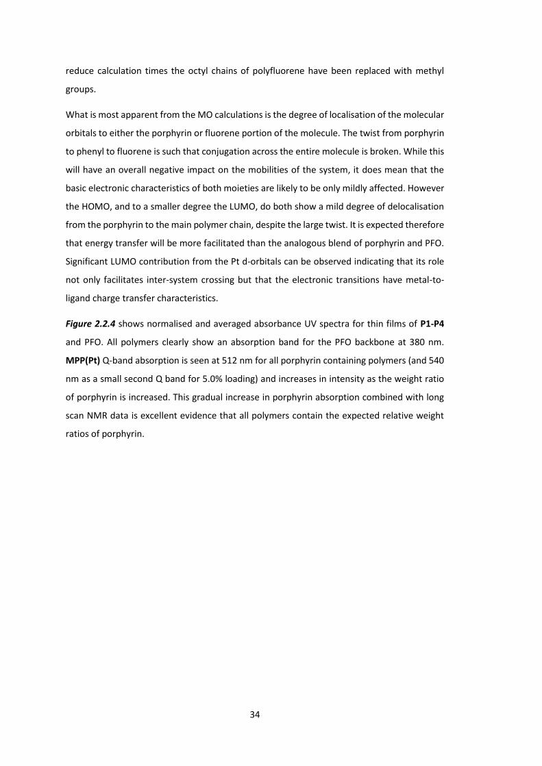
The energy levels and molecular orbitals of PF MPP(Pt) were calculated using B3LYP DFT in
silico using basis set 6-31G* for C, H and N and LanL2DZ for Pt. Figure 2.2.3 shows the HOMO
and LUMO levels of an approximation of a porphyrin containing portion of the polymer. To
PF MPP(Pt)
P4
P3
P2
P1
a/b c/d
34
reduce calculation times the octyl chains of polyfluorene have been replaced with methyl
groups.
What is most apparent from the MO calculations is the degree of localisation of the molecular
orbitals to either the porphyrin or fluorene portion of the molecule. The twist from porphyrin
to phenyl to fluorene is such that conjugation across the entire molecule is broken. While this
will have an overall negative impact on the mobilities of the system, it does mean that the
basic electronic characteristics of both moieties are likely to be only mildly affected. However
the HOMO, and to a smaller degree the LUMO, do both show a mild degree of delocalisation
from the porphyrin to the main polymer chain, despite the large twist. It is expected therefore
that energy transfer will be more facilitated than the analogous blend of porphyrin and PFO.
Significant LUMO contribution from the Pt d-orbitals can be observed indicating that its role
not only facilitates inter-system crossing but that the electronic transitions have metal-to-
ligand charge transfer characteristics.
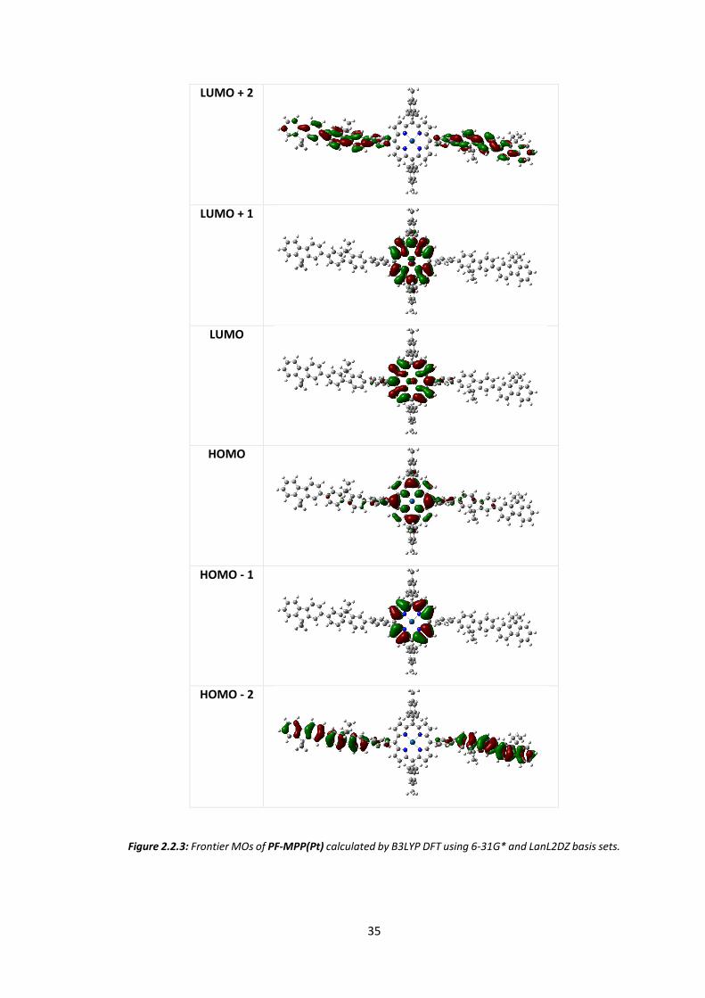
Figure 2.2.4 shows normalised and averaged absorbance UV spectra for thin films of P1-P4
and PFO. All polymers clearly show an absorption band for the PFO backbone at 380 nm.
MPP(Pt) Q-band absorption is seen at 512 nm for all porphyrin containing polymers (and 540
nm as a small second Q band for 5.0% loading) and increases in intensity as the weight ratio
of porphyrin is increased. This gradual increase in porphyrin absorption combined with long
scan NMR data is excellent evidence that all polymers contain the expected relative weight
ratios of porphyrin.
35
LUMO + 2
LUMO + 1
LUMO
HOMO
HOMO - 1
HOMO - 2
Figure 2.2.3: Frontier MOs of PF-MPP(Pt) calculated by B3LYP DFT using 6-31G* and LanL2DZ basis sets.
36
300 400 500 600 700 800 900 1000
0.0
0.2
0.4
0.6
0.8
1.0
1.2
Nor
mal
ised
Abs
orpt
ion
Wavelength (nm)
PFO 0.5% 1.0% 2.0% 5.0%
480 500 520 5400.00
0.01
0.02
0.03
0.04
0.05
0.06
0.07
0.08
Figure 2.2.4: Thin film UV data for all PF MPP(Pt) polymers. All data is normalised and is taken as the
average of 2 measurements. Inset shows MPP(Pt) Q band absorption features.
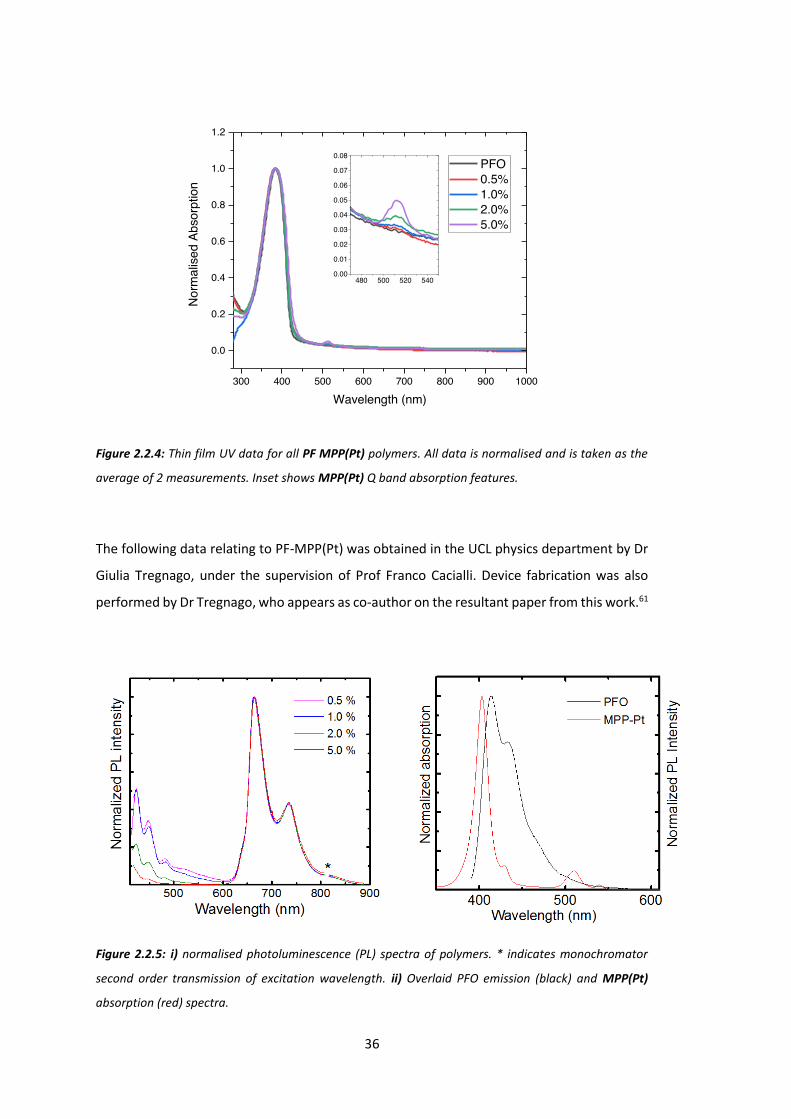
The following data relating to PF-MPP(Pt) was obtained in the UCL physics department by Dr
Giulia Tregnago, under the supervision of Prof Franco Cacialli. Device fabrication was also
performed by Dr Tregnago, who appears as co-author on the resultant paper from this work.61
Figure 2.2.5: i) normalised photoluminescence (PL) spectra of polymers. * indicates monochromator
second order transmission of excitation wavelength. ii) Overlaid PFO emission (black) and MPP(Pt)
absorption (red) spectra.
37
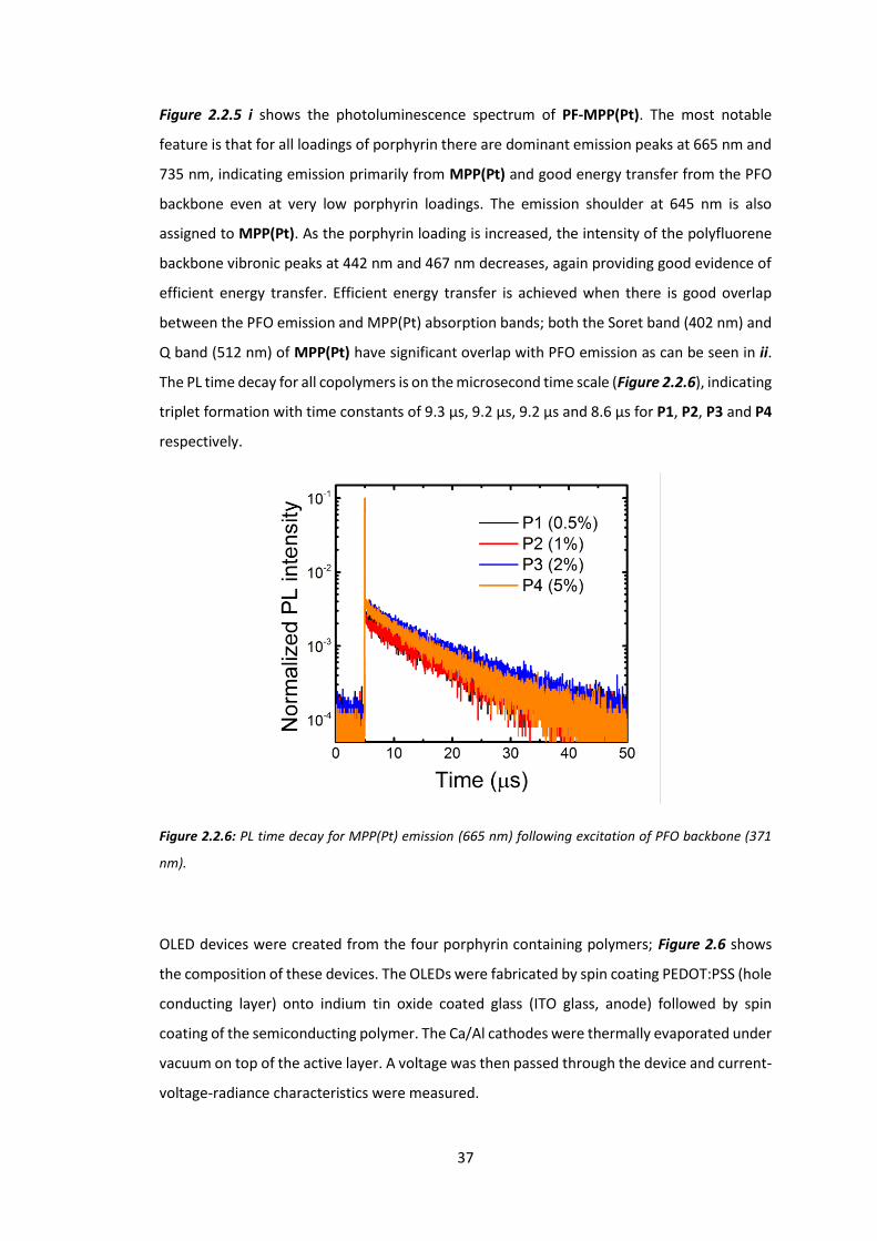
Figure 2.2.5 i shows the photoluminescence spectrum of PF-MPP(Pt). The most notable
feature is that for all loadings of porphyrin there are dominant emission peaks at 665 nm and
735 nm, indicating emission primarily from MPP(Pt) and good energy transfer from the PFO
backbone even at very low porphyrin loadings. The emission shoulder at 645 nm is also
assigned to MPP(Pt). As the porphyrin loading is increased, the intensity of the polyfluorene
backbone vibronic peaks at 442 nm and 467 nm decreases, again providing good evidence of
efficient energy transfer. Efficient energy transfer is achieved when there is good overlap
between the PFO emission and MPP(Pt) absorption bands; both the Soret band (402 nm) and
Q band (512 nm) of MPP(Pt) have significant overlap with PFO emission as can be seen in ii.
The PL time decay for all copolymers is on the microsecond time scale (Figure 2.2.6), indicating
triplet formation with time constants of 9.3 µs, 9.2 µs, 9.2 µs and 8.6 µs for P1, P2, P3 and P4
respectively.
Figure 2.2.6: PL time decay for MPP(Pt) emission (665 nm) following excitation of PFO backbone (371
nm).
OLED devices were created from the four porphyrin containing polymers; Figure 2.6 shows
the composition of these devices. The OLEDs were fabricated by spin coating PEDOT:PSS (hole
conducting layer) onto indium tin oxide coated glass (ITO glass, anode) followed by spin
coating of the semiconducting polymer. The Ca/Al cathodes were thermally evaporated under
vacuum on top of the active layer. A voltage was then passed through the device and current-
voltage-radiance characteristics were measured.

38
Figure 2.2.7: Normalized electroluminescence (EL) spectra for the polymers as part of a device. The
LED structure is reported. The active layer thickness is ~100 nm and the device area is 3.5 mm2. Key
refers to porphyrin feed ratio /%.
Polymer Porphyrin
loading /%
EQEa /% Vonb / V Luminancea /
Cd/m2
P1 0.5 0.17 ± 0.01 10.7 ± 0.2 14.8 ± 0.7
P2 1.0 0.28 ± 0.04 7.6 ± 0.2 23.8 ± 2.9
P3 2.0 0.48 ± 0.01 8.3 ± 0.3 31.1 ± 0.8
P4 5.0 0.28 ± 0.04 9.3 ± 0.4 9.9 ± 0.4
Table 2.2.2: Summary of LED performance. aMeasured at 30 mA/cm2. bIntercept of the I-V curve with
the x-axis in a semi-log plot.
All polymers display dominant EL peaks at 665 and 736 nm, concurrent with results from the
PL specta. P1 and P2 both display weak EL below 600 nm that is not present for higher
porphyrin w/w. This may be due to emission from a MPP(Pt) singlet state (previously reported
for similar systems to occur around 580 nm),65-66 or possibly because of oxidative defects on
the polyfluorene backbone.67 P3 and P4 both show pure electrophosphoresence (i.e. only
emission from a triplet state located on MPP(Pt)).

39
The highest efficiency LED is P3 (2.0% loading) with an external quantum efficiency (EQE) of
0.48%, a luminance of 23.8 Cd/m2 and the lowest turn-on voltage (8.3 V). This result is very
encouraging when compared to similar red/NIR emitting compounds from the literature,
especially when taking into account the LEDs are not optimised for charge collection and
extraction.68-69
A series of conjugated polymers based on polyfluorene have been prepared with various
weight percentages of a phosphorescent porphyrin, MPP(Pt), attached via the meso position.
Emission of the polymers was found to be from the triplet state of the porphyrin, as shown by
the microsecond lifetime of emission. 0.5% and 1% loadings of porphyrin retained some
fluorescence from the polymer backbone. Fluoresence was not observed for higher porphyrin
loadings, indicating good energy transfer from polymer to porphyrin.
The triplet state of MPP(Pt) has been clearly shown to be readily populated. The second series
of polymers synthesised with this porphyrin as comonomer sought to utilise the populated
triplet state to back-transfer onto the polymer backbone to facilitate triplet-triplet
annihilation (TTA).
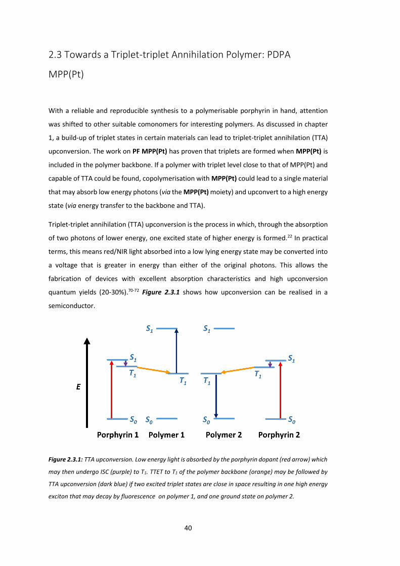
40
2.3 Towards a Triplet-triplet Annihilation Polymer: PDPA
MPP(Pt)
With a reliable and reproducible synthesis to a polymerisable porphyrin in hand, attention
was shifted to other suitable comonomers for interesting polymers. As discussed in chapter
1, a build-up of triplet states in certain materials can lead to triplet-triplet annihilation (TTA)
upconversion. The work on PF MPP(Pt) has proven that triplets are formed when MPP(Pt) is
included in the polymer backbone. If a polymer with triplet level close to that of MPP(Pt) and
capable of TTA could be found, copolymerisation with MPP(Pt) could lead to a single material
that may absorb low energy photons (via the MPP(Pt) moiety) and upconvert to a high energy
state (via energy transfer to the backbone and TTA).
Triplet-triplet annihilation (TTA) upconversion is the process in which, through the absorption
of two photons of lower energy, one excited state of higher energy is formed.22 In practical
terms, this means red/NIR light absorbed into a low lying energy state may be converted into
a voltage that is greater in energy than either of the original photons. This allows the
fabrication of devices with excellent absorption characteristics and high upconversion
quantum yields (20-30%).70-72 Figure 2.3.1 shows how upconversion can be realised in a
semiconductor.
Figure 2.3.1: TTA upconversion. Low energy light is absorbed by the porphyrin dopant (red arrow) which
may then undergo ISC (purple) to T1. TTET to T1 of the polymer backbone (orange) may be followed by
TTA upconversion (dark blue) if two excited triplet states are close in space resulting in one high energy
exciton that may decay by fluorescence on polymer 1, and one ground state on polymer 2.

41
Firstly, an exciton is formed on the porphyrin dopant as an electron is promoted from S0 to S1
(the only allowable transition at low energy excitation) (red). S1 may then decay to T1 (if the
dopant contains a heavy metal which promotes spin orbit coupling) through intersystem
crossing (ISC) (purple). This triplet state may then undergo the allowable transition to the
triplet state of the upconverting polymer (triplet triplet energy transfer (TTET)) (orange). This
transition is a Dexter process, and as such the donor and acceptor must be within a close range
of each other.73 By copolymerising the dopant with a known polymer, this contact is
controllable and the energy transfer more likely to occur. Once two excitons have been
transferred to the main polymer chain and are within a close distance of each other, TTA
upconversion can result in a single exciton on S1 (dark blue). This exciton may then decay to
release energy, either through emission of low wavelength light or extraction of a higher
voltage than was contained within either of the initially absorbed states. When this system is
placed in a solar cell, overall efficiency is increased as previously unabsorbed, low energy
photons can now be absorbed and utilised.
Acenes are known to efficiently undergo triplet-triplet annihilation when sensitised with
triplets.70 It was our hypothesis that a polymer containing an acene in the backbone with a
triplet state close to that of MPP(Pt) (ideally, slightly lower in energy) may be able to absorb
high wavelength, low energy photons (via the porphyrin Soret band) and subsequently
upconvert two such excitons to a higher energy state.
Recent examples of TTA upconversion uses a blend of a diphenylanthracene tethered polymer
and a simple porphyrin.74-75 Blends are not ideal for this process as the proximity of donor and
acceptor (for TTET) is not guaranteed; porphyrins are known to form aggregates readily.76-77
By incorporating both donor and acceptor into a single polymer the donor-acceptor distances
are much more regimented. If both are incorporated into a conjugated polymer, energy
transfer should be even further improved.
A diphenylanthracene that is polymerisable requires some structural changes from plain
diphenylanthracene however, primarily to increase solubility. Figure 2.3.2 shows the target
for this synthesis, poly-4’,4’’-(2,3,6,7-(octyloxy)-9,10-diphenylanthracene-alt-1,4-phenyl)-ran-
(4’,4’’-5,15-dimesityl-10,20-diphenylporphyrin(Pt)-alt-1,4-phenyl) (PDPA MPP(Pt)).
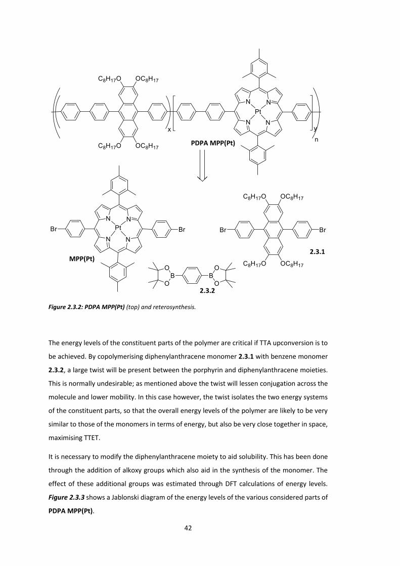
42
Figure 2.3.2: PDPA MPP(Pt) (top) and reterosynthesis.
The energy levels of the constituent parts of the polymer are critical if TTA upconversion is to
be achieved. By copolymerising diphenylanthracene monomer 2.3.1 with benzene monomer
2.3.2, a large twist will be present between the porphyrin and diphenylanthracene moieties.
This is normally undesirable; as mentioned above the twist will lessen conjugation across the
molecule and lower mobility. In this case however, the twist isolates the two energy systems
of the constituent parts, so that the overall energy levels of the polymer are likely to be very
similar to those of the monomers in terms of energy, but also be very close together in space,
maximising TTET.
It is necessary to modify the diphenylanthracene moiety to aid solubility. This has been done
through the addition of alkoxy groups which also aid in the synthesis of the monomer. The
effect of these additional groups was estimated through DFT calculations of energy levels.
Figure 2.3.3 shows a Jablonski diagram of the energy levels of the various considered parts of
PDPA MPP(Pt).
PDPA MPP(Pt)
MPP(Pt) 2.3.1
2.3.2

43
Polymer T1 / eV T2 / eV T3 / eV S1 / eV S2 / eV S3 / eV
Ant3 1.88 1.88 1.88 3.10 3.13 3.15
MPP(Pt) 1.83 1.84 2.17 2.19 2.48 2.48
MPP(Pd) 1.74 1.75 2.11 2.13 2.41 2.41
Figure 2.3.3: : Jablonski diagram of considered monomers for anthracene TTA upconversion polymers
(top) with diagrams of calculated structures (middle) and tabulated quantitative data (bottom)
calculated by B3LYP DFT using 6-31G* and LanL2DZ basis sets.
M = Pt MPP(Pt) M = Pd MPP(Pd)
Ant3

44
Consideration of the data in Figure 2.3.3 shows that polymerisation of a tetraalkoxy
anthracene with MPP(Pt) would (if the energy levels remain unaffected) result in a polymer
containing a donor with a triplet energy of 1.83 eV and an acceptor with T1 of 1.88 eV. This
means the desired transition is energetically unfavourable, however the difference is very
small (0.05 eV) and well within the expected differences between DFT and experiment
(differences arise from molecules being treated as in the gas phase, estimating triplet state
energy levels that are often not well calculated in DFT and limits on the size of the ‘polymer’
in silico). It is thought that the transition would occur with these energy levels, especially
considering that energy transfer to T1 of the anthracene may then result in TTA upconversion,
thereby lowering the population density of that state. In the platinum porphyrin,
phosphorescence is a likely loss mechanism however. This would be mitigated slightly if the
metal were changed to palladium (palladium, as a lighter metal, has a lower rate of
intersystem crossing from spin-orbit coupling). As can be seen from Figure 2.3.3 however,
MPP(Pd) has an even lower T1 and is less likely to result in a successful upconverting polymer.
The decision therefore was made to create anthracene polymers containing MPP(Pt).
Scheme 2.3.1: Synthesis of anthracene monomer 2.3.1.
Diphenylanthracene monomer 2.3.1 was synthesised as in Scheme 2.3.1. A tetramethoxy
analogue has been previously synthesised from veratrole by Xia et al.78 Starting from catechol
2.3.3, dialkylation yields an octyl analogue of veratrole, 1,2-bis(octyloxy)benzene 2.3.4. Xia’s
conditions for anthracene formation are similar to Lindsey’s porphyrin formation method. 1,2-
bis(octyloxy)benzene 2.3.4 is first reacted with an aldehyde in the presence of acid which
forms the skeletal ring structure, and an oxidant is then added to oxidise the ring structure
2.3.1
2.3.3 2.3.4
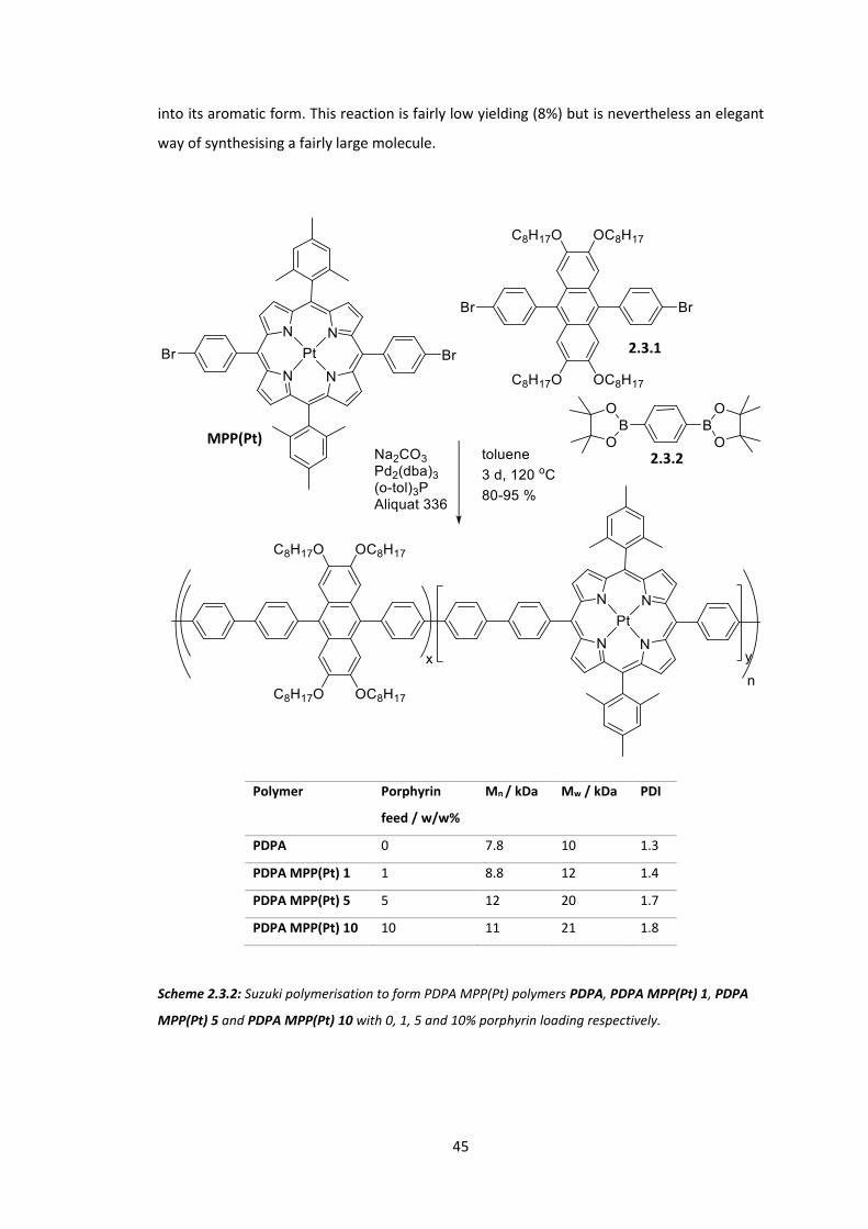
45
into its aromatic form. This reaction is fairly low yielding (8%) but is nevertheless an elegant
way of synthesising a fairly large molecule.
Polymer Porphyrin
feed / w/w%
Mn / kDa Mw / kDa PDI
PDPA 0 7.8 10 1.3
PDPA MPP(Pt) 1 1 8.8 12 1.4
PDPA MPP(Pt) 5 5 12 20 1.7
PDPA MPP(Pt) 10 10 11 21 1.8
Scheme 2.3.2: Suzuki polymerisation to form PDPA MPP(Pt) polymers PDPA, PDPA MPP(Pt) 1, PDPA
MPP(Pt) 5 and PDPA MPP(Pt) 10 with 0, 1, 5 and 10% porphyrin loading respectively.
MPP(Pt)
2.3.1
2.3.2

46
4 polymers of various porphyrin loadings were synthesised via a Suzuki polymerisation,
Scheme 2.3.2. The sizes of all polymers was 7.8 – 12 kDa (Mn), which is an acceptable range
for physical testing. The absorbance spectra were then obtained for each polymer in
chlorobenzene solution.
400 500 6000.0
0.2
0.4
0.6
0.8
1.0
1.2
1.4
Nor
mal
ised
Abs
orba
nce
Wavelength / nm
PDPA PDPA MPP(Pt) 1 PDPA MPP(Pt) 5 PDPA MPP(Pt) 10
475 500 525 550 5750.00
0.05
0.10
0.15
0.20
0.25
0.30
Figure 2.3.4: Normalised absorption spectrum for PDPA MPP(Pt) polymers in chlorobenzene solution.
Inset shows MPP(Pt) Q band absorption.
All polymers show (predominantly) diphenylanthracene absorption bands at 382 nm and
between 400 and 410 nm, Figure 2.3.4. Interestingly, there is a shift to stronger absorption at
longer wavelengths as porphyrin loading is increased (ie. as porphyrin loading is raised, the
peak at 400-410 becomes more dominant and more red-shifted). This is thought to be due to
increased contribution from the Soret band of the porphyrin, denoting the S2 ← S0 transition.
Similar to PF MPP(Pt), the MPP(Pt) Q-band absorption peaks are seen at 515 nm (and 543 nm
for higher porphyrin loadings) which indicates the S1 ← S0 transitions. Q-band absorption is
seen to increase with porphyrin loading, indicating the w/w are as expected.
The molecular weights of all polymers was found to be modest (due to solubility resulting in
precipitation during the reaction) but similar to each other and therefore comparible. The
incorporation ratios of MPP(Pt) containing polymers were as expected, Table 2.3.1. An
accurate value of the incorporation ratio of PDPA MPP(Pt) 1 could not be obtained from NMR
studies due to the low amounts of porphyrin present, however the presence of Q bands in the
absorbance spectra clearly shows porphyrin incorporation. The energy gap was found to be
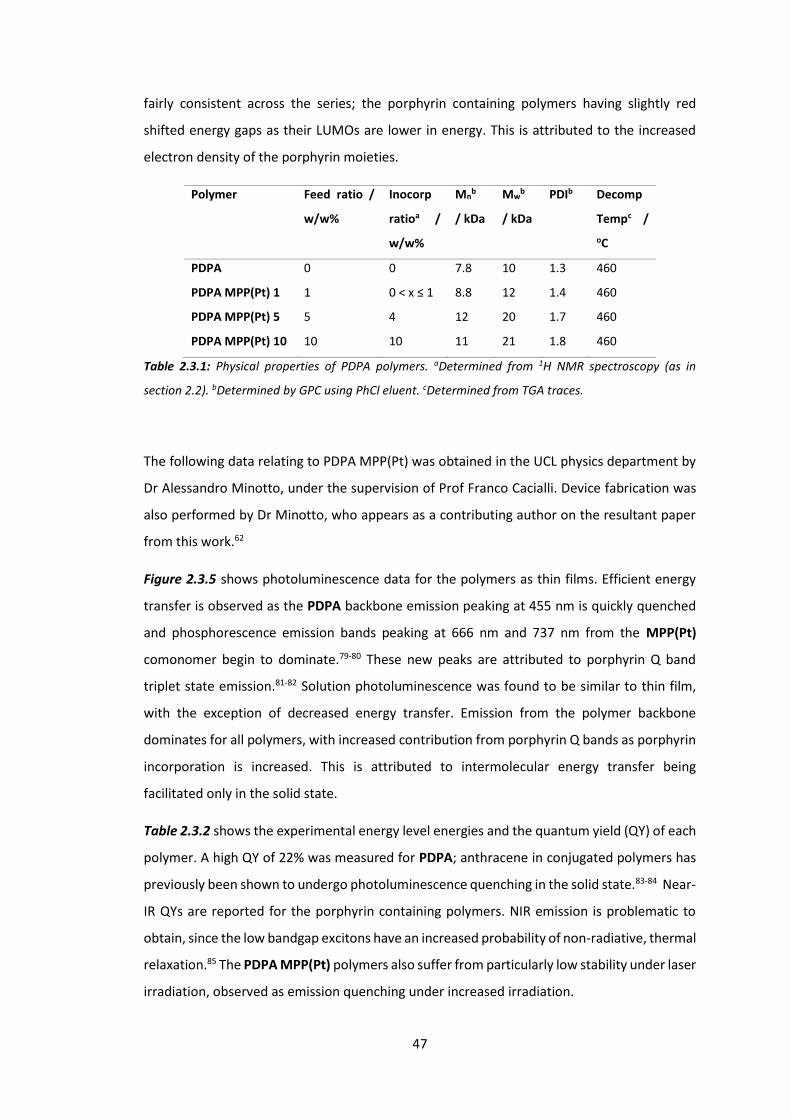
47
fairly consistent across the series; the porphyrin containing polymers having slightly red
shifted energy gaps as their LUMOs are lower in energy. This is attributed to the increased
electron density of the porphyrin moieties.
Polymer Feed ratio /
w/w%
Inocorp
ratioa /
w/w%
Mnb
/ kDa
Mwb
/ kDa
PDIb Decomp
Tempc / oC
PDPA 0 0 7.8 10 1.3 460
PDPA MPP(Pt) 1 1 0 < x ≤ 1 8.8 12 1.4 460
PDPA MPP(Pt) 5 5 4 12 20 1.7 460
PDPA MPP(Pt) 10 10 10 11 21 1.8 460
Table 2.3.1: Physical properties of PDPA polymers. aDetermined from 1H NMR spectroscopy (as in
section 2.2). bDetermined by GPC using PhCl eluent. cDetermined from TGA traces.
The following data relating to PDPA MPP(Pt) was obtained in the UCL physics department by
Dr Alessandro Minotto, under the supervision of Prof Franco Cacialli. Device fabrication was
also performed by Dr Minotto, who appears as a contributing author on the resultant paper
from this work.62
Figure 2.3.5 shows photoluminescence data for the polymers as thin films. Efficient energy
transfer is observed as the PDPA backbone emission peaking at 455 nm is quickly quenched
and phosphorescence emission bands peaking at 666 nm and 737 nm from the MPP(Pt)
comonomer begin to dominate.79-80 These new peaks are attributed to porphyrin Q band
triplet state emission.81-82 Solution photoluminescence was found to be similar to thin film,
with the exception of decreased energy transfer. Emission from the polymer backbone
dominates for all polymers, with increased contribution from porphyrin Q bands as porphyrin
incorporation is increased. This is attributed to intermolecular energy transfer being
facilitated only in the solid state.
Table 2.3.2 shows the experimental energy level energies and the quantum yield (QY) of each
polymer. A high QY of 22% was measured for PDPA; anthracene in conjugated polymers has
previously been shown to undergo photoluminescence quenching in the solid state.83-84 Near-
IR QYs are reported for the porphyrin containing polymers. NIR emission is problematic to
obtain, since the low bandgap excitons have an increased probability of non-radiative, thermal
relaxation.85 The PDPA MPP(Pt) polymers also suffer from particularly low stability under laser
irradiation, observed as emission quenching under increased irradiation.
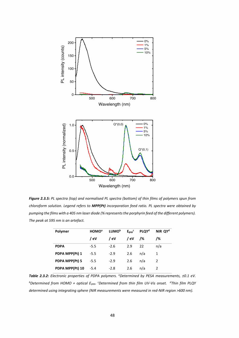
48
500 600 700 8000
50
100
150
200 0% 1% 5% 10%
PL in
tens
ity (c
ount
s)
Wavelength (nm)
500 600 700 8000.0
0.5
1.0
Q*(0,1)
PL in
tens
ity (n
orm
aliz
ed)
Wavelength (nm)
0% 1% 5% 10%
Q*(0,0)
Figure 2.3.5: PL spectra (top) and normalised PL spectra (bottom) of thin films of polymers spun from
chloroform solution. Legend refers to MPP(Pt) incorporation feed ratio. PL spectra were obtained by
pumping the films with a 405 nm laser diode (% represents the porphyrin feed of the different polymers).
The peak at 595 nm is an artefact.
Polymer HOMOa
/ eV
LUMOb
/ eV
Egapc
/ eV
PLQYd
/%
NIR QYd
/%
PDPA -5.5 -2.6 2.9 22 n/a
PDPA MPP(Pt) 1 -5.5 -2.9 2.6 n/a 1
PDPA MPP(Pt) 5 -5.5 -2.9 2.6 n/a 2
PDPA MPP(Pt) 10 -5.4 -2.8 2.6 n/a 2
Table 2.3.2: Electronic properties of PDPA polymers. aDetermined by PESA measurements, ±0.1 eV. bDetermined from HOMO + optical Egap. cDetermined from thin film UV-Vis onset. dThin film PLQY
determined using integrating sphere (NIR measurements were measured in red-NIR region >600 nm).

49
The instability of these systems is attributed to a high concentration of triplet states. This again
implies energy transfer from polymer backbone (where singlet excitons are formed with 405
nm laser pulse) to porphyrin is an efficient process. It is thought the triplet states result in
singlet oxygen generation, or possibly lead to anthracene cyclisation reactions. Figure 2.3.6
shows the PL spectra of the 5 and 10% porphyrin loading polymers when excited with a 532
nm laser pulse.
400 500 600 700 800
0.0
0.5
1.0
PL in
tens
ity (n
orm
aliz
ed)
Wavelength (nm)
PDPA MPP(Pt) 5 PDPA MPP(Pt) 10
Figure 2.3.6: PL spectra of PDPA MPP(Pt) 5 (blue) and PDPA MPP(Pt) 10 (green) thin films excited with
532 nm laser pulse. PDPA MPP(Pt) 1 showed similar data, but with high background noise.
Excitation of the porphyrin was hypothesised to lead to TTA on the anthracene-containing
backbone (through ISC and TTET). This would be visualised by emission at 450 nm after an
excitation of the porphyrin at 532 nm. From Figure 2.3.6, we observe no emission from the
polymer backbone, implying TTA does not significantly occur in these systems. A similar PL
trace was obtained for PDPA MPP(Pt) 1 but has not been included for clarity, as it comprised
a high background noise.
Despite no TTA occurring, each polymer was incorporated into an OLED device. The structure
of the devices is shown in Figure 2.3.7.
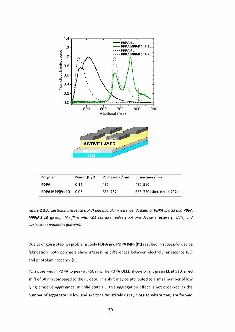
50
500 600 700 800 9000.0
0.2
0.4
0.6
0.8
1.0
1.2
1.4
Nor
mal
ised
Lum
ines
cenc
e
Wavelength (nm)
PDPA EL PDPA MPP(Pt) 10 EL PDPA PL PDPA MPP(Pt) 10 PL
Polymer Max EQE /% PL maxima / nm EL maxima / nm
PDPA 0.14 450 460, 510
PDPA MPP(Pt) 10 0.03 666, 737 666, 760 (shoulder at 737)
Figure 2.3.7: Electroluminescence (solid) and photoluminescence (dashed) of PDPA (black) and PDPA
MPP(Pt) 10 (green) thin films with 405 nm laser pulse (top) and device structure (middle) and
luminescent properties (bottom).
Due to ongoing stability problems, only PDPA and PDPA MPP(Pt) resulted in successful device
fabrication. Both polymers show interesting differences between electroluminescence (EL)
and photoluminescence (PL).
PL is observed in PDPA to peak at 450 nm. The PDPA OLED shows bright green EL at 510, a red
shift of 60 nm compared to the PL data. This shift may be attributed to a small number of low
lying emissive aggregates. In solid state PL, this aggregation effect is not observed as the
number of aggregates is low and excitons radiatively decay close to where they are formed
51
before they may migrate to aggregate sites. Charges in the EL spectra however are driven from
either end of the device and therefore move through the semiconductor, moving through low-
energy sites found on the aggregating portions of the device. Excimers are formed and
emission from these lower lying states begins to dominate. Some non-aggregate emission is
observed in the EL at 460 nm. Aggregation in anthracene is facilitated by its large π system,
and solid-state aggregation has been observed in similar systems.86 The maximum EQE of
0.14% is reasonable for a non-optimised single layer device.
PDPA MPP(Pt) 10 shows very red emission almost entirely in the NIR (>700 nm) region. The
maximum EQE of 0.03% is close to the maximum values reported at the time for NIR light-
emitting polymers.51 A similar, but larger red shift is observed for this polymer. Two Q bands
are seen in the PL spectra at 666 nm and 737 nm. The EL spectrum shows a major peak at 760
nm, as well as a minor peak at 666 nm and a shoulder corresponding to the second Q band at
737 nm. This shows the new peak at 760 nm is not simply an increase in intensity of a peak
observed in the PL spectrum. The shift is again therefore attributed to excimer/exciplex
formation.
Interestingly, the EL emission of PDPA MPP(Pt) 10 is close to that of the much larger porphyrin
Pt(TPBP). By inducing aggregation, either polymer-porphyrin or porphyrin-porphyrin, a
simple, small porphyrin may emit at a much lower wavelength than previously expected. The
synthesis of larger porphyrins is discussed in chapter 3.
Although the initial aim of creating a polymer capable of TTA was unsuccessful, an interesting
aggregation-induced red shift of emission was detected. This observation formed the basis of
the resultant paper on this work, as NIR emitters are useful in terms of many applications such
as telecommunications and wound-healing.62

52
2.4 Conclusions
An A2B2 porphyrin was synthesised that may be copolymerised with appropriate copolymers
to create a polymer with a heavy metal incorporated into a covalently bound portion of the
polymer backbone. This has the advantage over blend systems of standardising the distance
between porphyrin and polymer, as well as discouraging phase separation and aggregation of
porphyrin. MPP(Pt) was incorporated into two polymeric systems.
The first polymer series synthesised was PF MPP(Pt). This polymer was synthesised with the
aim of increasing internal quantum efficiency by utilising triplet states formed on the polymer
backbone through charge injection. This was achieved through energy transfer to the
porphyrin moiety (singlets and triplets), where the lowest lying triplet state is populated as
higher lying singlets may undergo ISC facilitated by the heavy metal centre. Phosphorescence
is then observed. Pure electrophosphorescence is observed for loading of porphyrin of 2% and
above.
A second series of diphenylanthracene based polymers was also synthesised with MPP(Pt)
incorporated in various weight percentages. The initial aim of this synthesis was to create a
TTA capable system where low energy triplet excitons would transfer from the porphyrin to
the polymer backbone and undergo upconversion. This aim was not successful however,
possibly due to TTET not occurring from porphyrin to polymer. By modifying the structure of
porphyrin and/or diphenylanthracene monomers, it may be possible to enable TTET in a
similar system in the future. The resultant polymer series from this work did show interesting
characteristics however, namely an aggregation-induced red shift of emission. The highly
aggregating nature of anthracene allowed the formation of an emissive excimer (or possibly
exciplex) that is present in polymers with and without porphyrin comonomer. In the porphyrin
containing polymers, this red shift results in NIR emitting polymers. Since aggregation is
normally associated with loss mechanisms, this type of emission is not well studied in the
literature.

53
54
Chapter 3: Low Energy Triplet
Formation for TTA Polymers: Extended
Porphyrins
3.1 Introduction
In the previous chapter, an A2B2 porphyrin was synthesised and copolymerised to form
semiconducting polymers that utilise triplet states. In order to apply this technique to multiple
systems, the energy levels of interest on the porphyrin need to be tuneable so as to match
any polymer it is copolymerised with. By creating a larger, more conjugated porphyrin, more
of the solar spectrum may be absorbed and therefore more polymers may be applicable hosts
for TTA applications. This chapter will focus on work towards extended copolymerisable
porphyrins that have red shifted S1 and T1 compared to MPP(Pt), with the ultimate aim of the
creation of a polymer capable of TTA (thus low energy photons are converted into useful
voltages).
One way of extending the conjugated system of porphyrins is through the addition of phenyl
groups at the β positions.10 A4 porphyrins may be synthesised from 1-nitrocyclohexene
through 4,5,6,7-tetrahydroisoindole, however this added synthetic complexity is difficult to
realise in polymerisable porphyrins. An A4 β-extended porphyrin has been synthesised to be
used as a dopant in a blend system, but its application is beyond the scope of this body of
work.87
As detailed in chapter 2, A2B2 porphyrins may be incorporated covalently into a polymer
backbone. Extended A2B2 porphyrins have been previously reported as part of a larger
polymeric or macrocyclic system. Polyfluorene-co-5,15-bis((phenyl)ethynyl)-10,20-
dimesitylporphyrinato platinum(II) (PF PEMP(Pt)) is an analogous polymer to PF MPP(Pt).
Figure 3.1.1 shows how an alkynyl spacer unit between the porphyrin and phenyl moieties
can be advantageous in terms of charge transport.

55
Figure 3.1.1: Alkynyl spacer unit effect on backbone twisting. Non-planarity of biaryl bond is a problem
as conjugation is effectively broken, localising HOMO and LUMO to porphyrin/ flourene and therefore
reducing mobility and energy transfer. Addition of alkyne spacer reduces the steric clash of phenyl
hydrogens and restores planarity, resulting in greater charge transport, lower energy levels and red-
shifted emission.
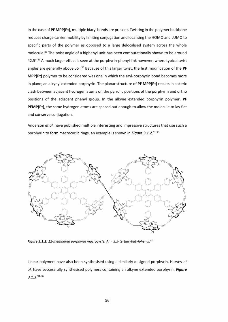
56
In the case of PF MPP(Pt), multiple biaryl bonds are present. Twisting in the polymer backbone
reduces charge carrier mobility by limiting conjugation and localising the HOMO and LUMO to
specific parts of the polymer as opposed to a large delocalised system across the whole
molecule.88 The twist angle of a biphenyl unit has been computationally shown to be around
42.5o.89 A much larger effect is seen at the porphyrin-phenyl link however, where typical twist
angles are generally above 55o.90 Because of this larger twist, the first modification of the PF
MPP(Pt) polymer to be considered was one in which the aryl-porphyrin bond becomes more
in plane; an alkynyl extended porphyrin. The planar structure of PF MPP(Pt) results in a steric
clash between adjacent hydrogen atoms on the pyrrolic positions of the porphyrin and ortho
positions of the adjacent phenyl group. In the alkyne extended porphyrin polymer, PF
PEMP(Pt), the same hydrogen atoms are spaced out enough to allow the molecule to lay flat
and conserve conjugation.
Anderson et al. have published multiple interesting and impressive structures that use such a
porphyrin to form macrocyclic rings, an example is shown in Figure 3.1.2.91-93
Figure 3.1.2: 12-membered porphyrin macrocycle. Ar = 3,5-tertiarybutylphenyl.91
Linear polymers have also been synthesised using a similarly designed porphyrin. Harvey et
al. have successfully synthesised polymers containing an alkyne extended porphyrin, Figure
3.1.3.94-96
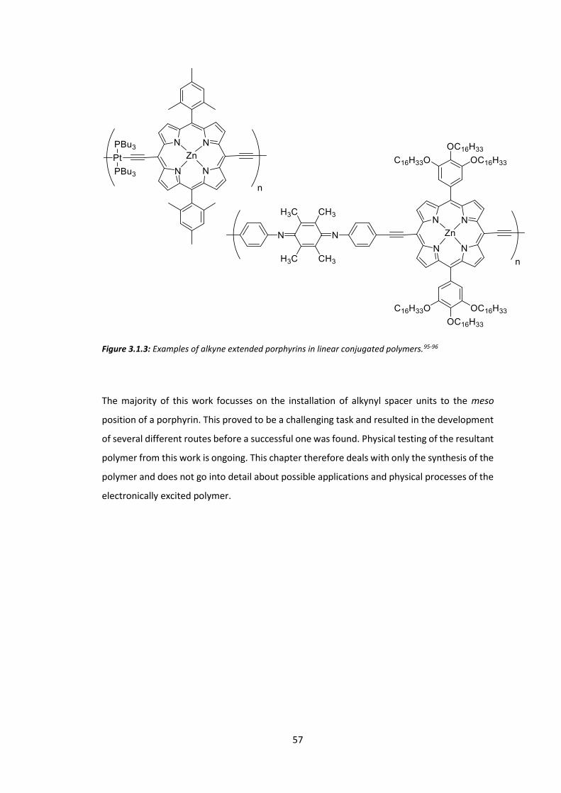
57
Figure 3.1.3: Examples of alkyne extended porphyrins in linear conjugated polymers.95-96
The majority of this work focusses on the installation of alkynyl spacer units to the meso
position of a porphyrin. This proved to be a challenging task and resulted in the development
of several different routes before a successful one was found. Physical testing of the resultant
polymer from this work is ongoing. This chapter therefore deals with only the synthesis of the
polymer and does not go into detail about possible applications and physical processes of the
electronically excited polymer.
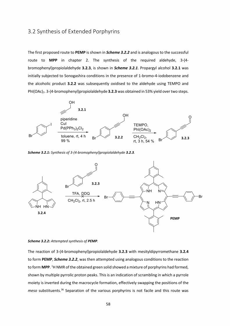
58
3.2 Synthesis of Extended Porphyrins
The first proposed route to PEMP is shown in Scheme 3.2.2 and is analogous to the successful
route to MPP in chapter 2. The synthesis of the required aldehyde, 3-(4-
bromophenyl)propiolaldehyde 3.2.3, is shown in Scheme 3.2.1. Propargyl alcohol 3.2.1 was
initially subjected to Sonogashira conditions in the presence of 1-bromo-4-iodobenzene and
the alcoholic product 3.2.2 was subsequently oxidised to the aldehyde using TEMPO and
PhI(OAc)2. 3-(4-bromophenyl)propiolaldehyde 3.2.3 was obtained in 53% yield over two steps.
Scheme 3.2.1: Synthesis of 3-(4-bromophenyl)propiolaldehyde 3.2.3.
Scheme 3.2.2: Attempted synthesis of PEMP.
The reaction of 3-(4-bromophenyl)propiolaldehyde 3.2.3 with mesityldipyrromethane 3.2.4
to form PEMP, Scheme 3.2.2, was then attempted using analogous conditions to the reaction
to form MPP. 1H NMR of the obtained green solid showed a mixture of porphyrins had formed,
shown by multiple pyrrolic proton peaks. This is an indication of scrambling in which a pyrrole
moiety is inverted during the macrocycle formation, effectively swapping the positions of the
meso substituents.36 Separation of the various porphyrins is not facile and this route was
3.2.2
3.2.4
PEMP
3.2.1
3.2.3
3.2.3
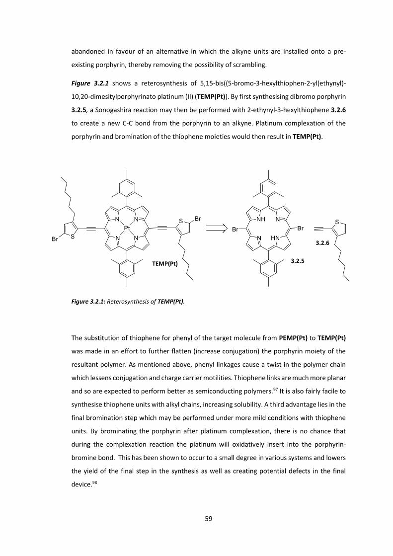
59
abandoned in favour of an alternative in which the alkyne units are installed onto a pre-
existing porphyrin, thereby removing the possibility of scrambling.
Figure 3.2.1 shows a reterosynthesis of 5,15-bis((5-bromo-3-hexylthiophen-2-yl)ethynyl)-
10,20-dimesitylporphyrinato platinum (II) (TEMP(Pt)). By first synthesising dibromo porphyrin
3.2.5, a Sonogashira reaction may then be performed with 2-ethynyl-3-hexylthiophene 3.2.6
to create a new C-C bond from the porphyrin to an alkyne. Platinum complexation of the
porphyrin and bromination of the thiophene moieties would then result in TEMP(Pt).
Figure 3.2.1: Reterosynthesis of TEMP(Pt).
The substitution of thiophene for phenyl of the target molecule from PEMP(Pt) to TEMP(Pt)
was made in an effort to further flatten (increase conjugation) the porphyrin moiety of the
resultant polymer. As mentioned above, phenyl linkages cause a twist in the polymer chain
which lessens conjugation and charge carrier motilities. Thiophene links are much more planar
and so are expected to perform better as semiconducting polymers.97 It is also fairly facile to
synthesise thiophene units with alkyl chains, increasing solubility. A third advantage lies in the
final bromination step which may be performed under more mild conditions with thiophene
units. By brominating the porphyrin after platinum complexation, there is no chance that
during the complexation reaction the platinum will oxidatively insert into the porphyrin-
bromine bond. This has been shown to occur to a small degree in various systems and lowers
the yield of the final step in the synthesis as well as creating potential defects in the final
device.98
TEMP(Pt) 3.2.5
3.2.6
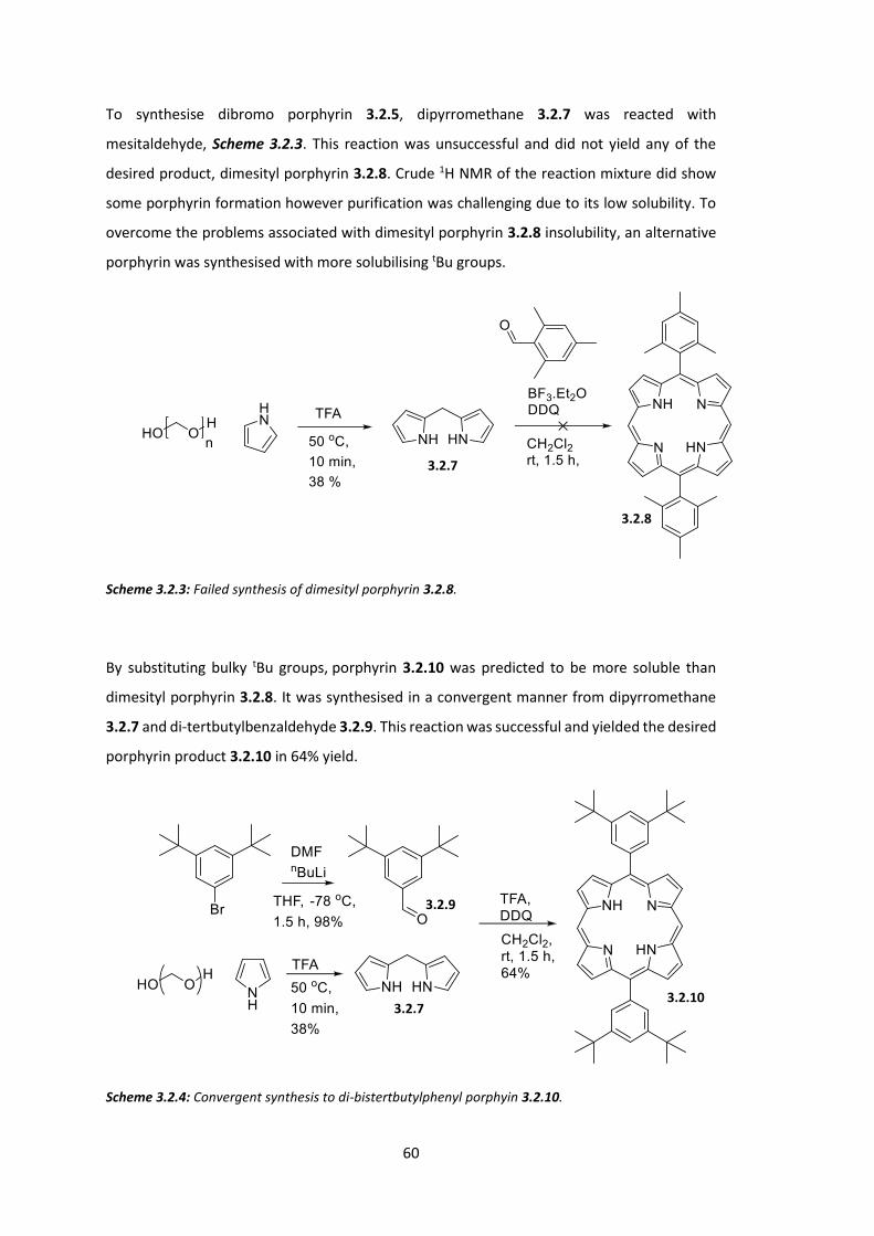
60
To synthesise dibromo porphyrin 3.2.5, dipyrromethane 3.2.7 was reacted with
mesitaldehyde, Scheme 3.2.3. This reaction was unsuccessful and did not yield any of the
desired product, dimesityl porphyrin 3.2.8. Crude 1H NMR of the reaction mixture did show
some porphyrin formation however purification was challenging due to its low solubility. To
overcome the problems associated with dimesityl porphyrin 3.2.8 insolubility, an alternative
porphyrin was synthesised with more solubilising tBu groups.
Scheme 3.2.3: Failed synthesis of dimesityl porphyrin 3.2.8.
By substituting bulky tBu groups, porphyrin 3.2.10 was predicted to be more soluble than
dimesityl porphyrin 3.2.8. It was synthesised in a convergent manner from dipyrromethane
3.2.7 and di-tertbutylbenzaldehyde 3.2.9. This reaction was successful and yielded the desired
porphyrin product 3.2.10 in 64% yield.
Scheme 3.2.4: Convergent synthesis to di-bistertbutylphenyl porphyin 3.2.10.
3.2.7
3.2.8
3.2.10 3.2.7
3.2.9

61
Bromination of porphyrin 3.2.10 proceeded as in Scheme 3.2.5 and gave the product, dibromo
porphyin 3.2.11 in 81% yield.
Scheme 3.2.5: Bromination of porphyin 3.2.10 to dibromo porphyin 3.2.11.
Synthesis of alkynyl thiophene 3.2.15 proceeded as in Scheme 3.2.6. Bromination of
hexylthiophene 3.2.12 with NBS was achieved with 70% yield and the subsequent Sonogashira
reaction with ethynyltrimethylsilane gave TMS protected alkynylhexylthiophene 3.2.14 in 86%
yield. Deprotection of the TMS group with base gave the desired alkynylhexylthiophene 3.2.15
in 68% yield, 41% yield over 3 steps from hexylthiophene 3.2.12.
Scheme 3.2.6: Synthesis of alkynylhexylthiophene 3.2.15.
The Sonogashira coupling of dibromo porphyin 3.2.11 and alkynylhexylthiophene 3.2.16 was
attempted as in Scheme 3.2.7.
3.2.10 3.2.11
3.2.15 3.2.12 3.2.13 3.2.14
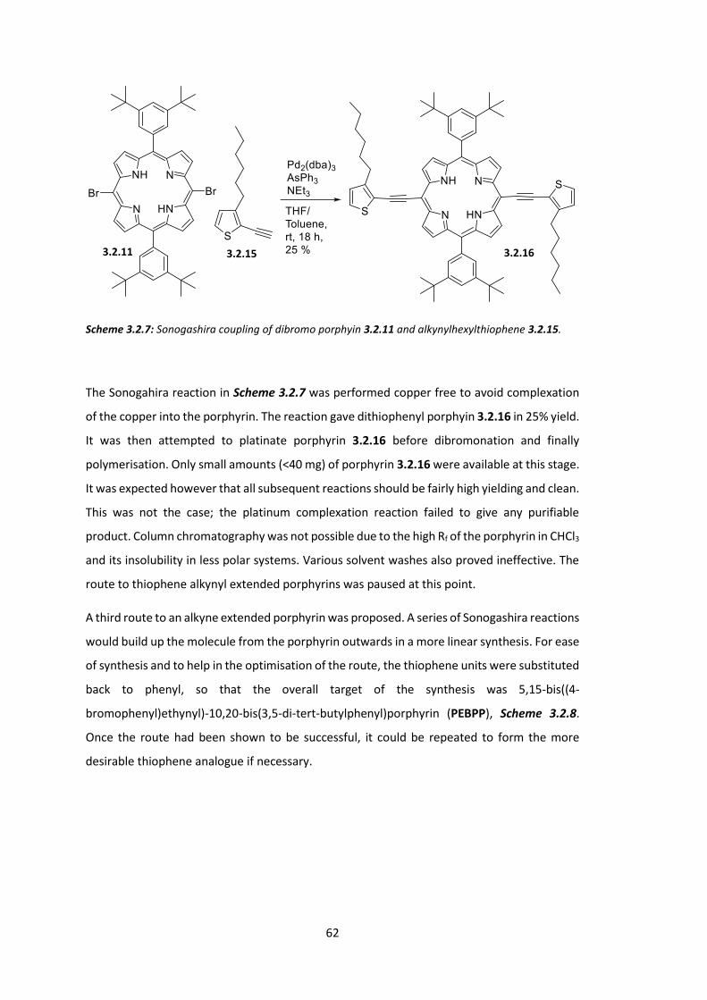
62
Scheme 3.2.7: Sonogashira coupling of dibromo porphyin 3.2.11 and alkynylhexylthiophene 3.2.15.
The Sonogahira reaction in Scheme 3.2.7 was performed copper free to avoid complexation
of the copper into the porphyrin. The reaction gave dithiophenyl porphyin 3.2.16 in 25% yield.
It was then attempted to platinate porphyrin 3.2.16 before dibromonation and finally
polymerisation. Only small amounts (<40 mg) of porphyrin 3.2.16 were available at this stage.
It was expected however that all subsequent reactions should be fairly high yielding and clean.
This was not the case; the platinum complexation reaction failed to give any purifiable
product. Column chromatography was not possible due to the high Rf of the porphyrin in CHCl3
and its insolubility in less polar systems. Various solvent washes also proved ineffective. The
route to thiophene alkynyl extended porphyrins was paused at this point.
A third route to an alkyne extended porphyrin was proposed. A series of Sonogashira reactions
would build up the molecule from the porphyrin outwards in a more linear synthesis. For ease
of synthesis and to help in the optimisation of the route, the thiophene units were substituted
back to phenyl, so that the overall target of the synthesis was 5,15-bis((4-
bromophenyl)ethynyl)-10,20-bis(3,5-di-tert-butylphenyl)porphyrin (PEBPP), Scheme 3.2.8.
Once the route had been shown to be successful, it could be repeated to form the more
desirable thiophene analogue if necessary.
3.2.11 3.2.15 3.2.16
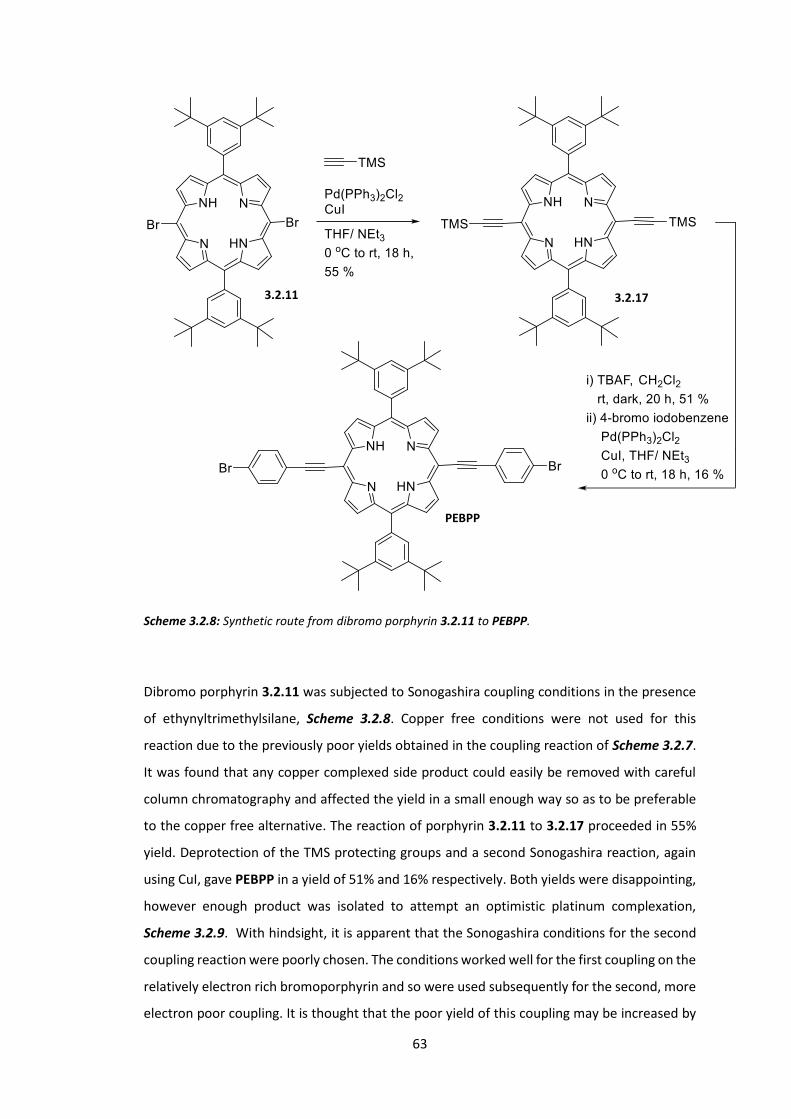
63
Scheme 3.2.8: Synthetic route from dibromo porphyrin 3.2.11 to PEBPP.
Dibromo porphyrin 3.2.11 was subjected to Sonogashira coupling conditions in the presence
of ethynyltrimethylsilane, Scheme 3.2.8. Copper free conditions were not used for this
reaction due to the previously poor yields obtained in the coupling reaction of Scheme 3.2.7.
It was found that any copper complexed side product could easily be removed with careful
column chromatography and affected the yield in a small enough way so as to be preferable
to the copper free alternative. The reaction of porphyrin 3.2.11 to 3.2.17 proceeded in 55%
yield. Deprotection of the TMS protecting groups and a second Sonogashira reaction, again
using CuI, gave PEBPP in a yield of 51% and 16% respectively. Both yields were disappointing,
however enough product was isolated to attempt an optimistic platinum complexation,
Scheme 3.2.9. With hindsight, it is apparent that the Sonogashira conditions for the second
coupling reaction were poorly chosen. The conditions worked well for the first coupling on the
relatively electron rich bromoporphyrin and so were used subsequently for the second, more
electron poor coupling. It is thought that the poor yield of this coupling may be increased by
3.2.11 3.2.17
PEBPP

64
changing the conditions, perhaps to those used in Scheme 3.2.7, although this was never
trialled.99
Scheme 3.2.9: Failed attempt at a platinum complexation of PEBPP.
As previously, the platinum complexation reaction did not give any product and consumed all
starting material. This reaction was performed on a very small scale and again there were
challenges involved with purifying the compound. This reaction and route was abandoned. It
was thought that the problems associated with platinum complexation could be solvable with
higher heating temperatures (ie. more forcing conditions). Separate work conducted within
the group has shown that temperature can have a large effect on these reactions. It was also
considered that the platinum starting material could be interacting with the alkyne, resulting
in several products.
The successful synthesis of PEBPP was very encouraging, despite the low quantities obtained.
It was planned that the 7-step synthesis would therefore have been attempted a second time,
with a concentrated effort on maintaining good yields to provide enough PEBPP for a
hopefully successful platinum complexation reaction with alternative conditions or possibly
an alternative metal halide starting material. A more efficient alternative presented itself
however. A newly published paper by Nowak-Król et al showed a modified Lindsey procedure
for the formation of trans A2B2 porphyrins from alkynyl aldehydes that had dramatically
reduced scrambling.100 By performing the acid catalysed porphyrinogen formation step in a
non-ideal solvent (THF with H2O), the starting aldehyde and dipyrromethane are soluble
enough to remain in solution and react while the porphyrinogen is insoluble and forms a
PEBPP
PEBPP(Pt)

65
suspension, reducing the likelihood of scrambling. The acid is then removed before the
porphyrinogen is oxidised to a porphyrin with DDQ (or another suitable oxidant).
Using this method, PEMP was successfully synthesised directly from 4-
bromobenzylalkynylaldehyde 3.2.3 and mesityldipyrromethane 3.2.4, Scheme 3.2.10. The
yield was very low (1% isolated yeild), however this is thought to be caused by the purification
technique used (long silica column rather than short silica plug) rather than an inherent result
of the reaction. Enough product was obtained to attempt a series of different metalation
complexation reactions. Table 3.2.1 summarises the results of the metal complexation
experiments.
Scheme 3.2.10: Successful direct synthesis of PEMP based on the work of Nowak-Król et al.100
Metalation
reagent
Solvent Temperature
/ oC
Time
/ h
Result
PtCl2 Benzonitrile 220 18 Starting material destroyed
Pd(OAc)2 CHCl3 40 72 No reaction
Pd(OAc)2 Chlorobenzene 100 72 Starting material destroyed
Zn(OAc)2 CH2Cl2 25 7 No reaction
Table 3.2.1: Metalation attempts on PEMP.
The same conditions that were used to insert Pt(II) into MPP(Pt) were first trialled. It was
found that this resulted in a complicated mixture of aromatic compounds. Platinum is the
most common metal to be inserted for greatest inter system crossing potential in porphyrins
3.2.3
3.2.4
PEMP

66
but is expensive as a reagent. Palladium has relatively similar properties to platinum in terms
of its reactivity photophysics in complexes and, while similar in price, is more abundant and
allows us to explore different reaction conditions for metalation. If a set of conditions could
be found that successfully inserted palladium into the porphyrin in good yield then these
conditions could also be used with platinum. This would then give two porphyrins with good
intersystem crossing potentials that may be compared.
Using Pd(OAc)2 in 40 oC chloroform failed to affect the porphyrin in any way and starting
material was returned. When the solvent was changed to chlorobenzene so that the
temperature may be increased to 100 oC, a similar complex mixture of aromatic products was
observed to the initial platinum experiment.
The results of these experiments seemed to suggest that interaction with the alkyne moiety
of PEMP was faster than metal insertion; both metals are known to react with alkyne units.101
Zinc does not interact with alkynes in the same way and, although much lighter than platinum
and palladium, is capable of promoting intersystem crossing.102 The reaction with Zinc acetate
did not give any product by NMR however, and returned starting material unreacted.
To overcome the problems associated with metalation, the order in which the individual
reactions of the basic route were performed was changed. Metallation is usually performed
at the end of a synthetic route as the reagents are often expensive. However by inserting the
metal before the alkynyl units, it was hypothesised that the issues highlighted above may be
avoided. As the route was being changed we also changed the target porphyrin so as to
increase solubility which had been an additional challenge to experiment design and the
acquirement of NMRs.
Scheme 3.2.11: Early metal insertion and subsequent bromination leading to undesired Pt(IV) complex
3.2.19.
3.2.19 3.2.11 3.2.18

67
Pt(II) was first inserted into porphyrin 3.2.11 using standard metal insertion conditions and
proceeded in excellent yield to yield Pt(II) porphyrin 3.2.18. The normal bromination
conditions however resulted in an interesting Pt(IV) complex 3.2.19, rather than the expected
meso brominated porphyrin. Evidence for the formation of this structure is shown in Figure
3.2.2. While the structure was not fully identified (it was clearly not the desired product), the 1H NMR and mass spec data together show that 2 bromides have been added and that the
meso protons remain unreacted. This reaction was interesting from a purely scientific view,
however it was also problematic as it showed that any bromination reaction (at least one
which uses these conditions) after platinum insertion would not give the previously expected
product. Meso bromination was trialled on Pt(IV) porphyrin 3.2.19, but was unsuccessful.
Figure 3.2.2: Aromatic region 1H NMR (top) and EI mass spec (bottom left splitting pattern and bottom
right numerical data) of Pt(IV) porphyrin 3.2.19. Meso protons (red box) are visible in the NMR spectrum
but the parent ion found in the mass spectrum shows a weight and splitting pattern of a dibrominated
product.
df101_ei #6 RT: 0.75 AV: 1 NL: 3.02E5T: + c EI Full ms [ 59.50-1100.50]
1025 1030 1035 1040 1045m/z
0
5
10
15
20
25
30
35
40
45
50
55
60
65
70
75
80
85
90
95
100
Rel
ativ
e Ab
unda
nce
1036.281034.33
1037.25
1033.36
1038.24
1032.38
1039.21
1031.381040.201030.42
1041.151049.031042.091029.52
Theoretical Mass (C48H52Br2N4Pt): 1037.22065
Measured Mass: 1037.220067
Error: 0.6ppm
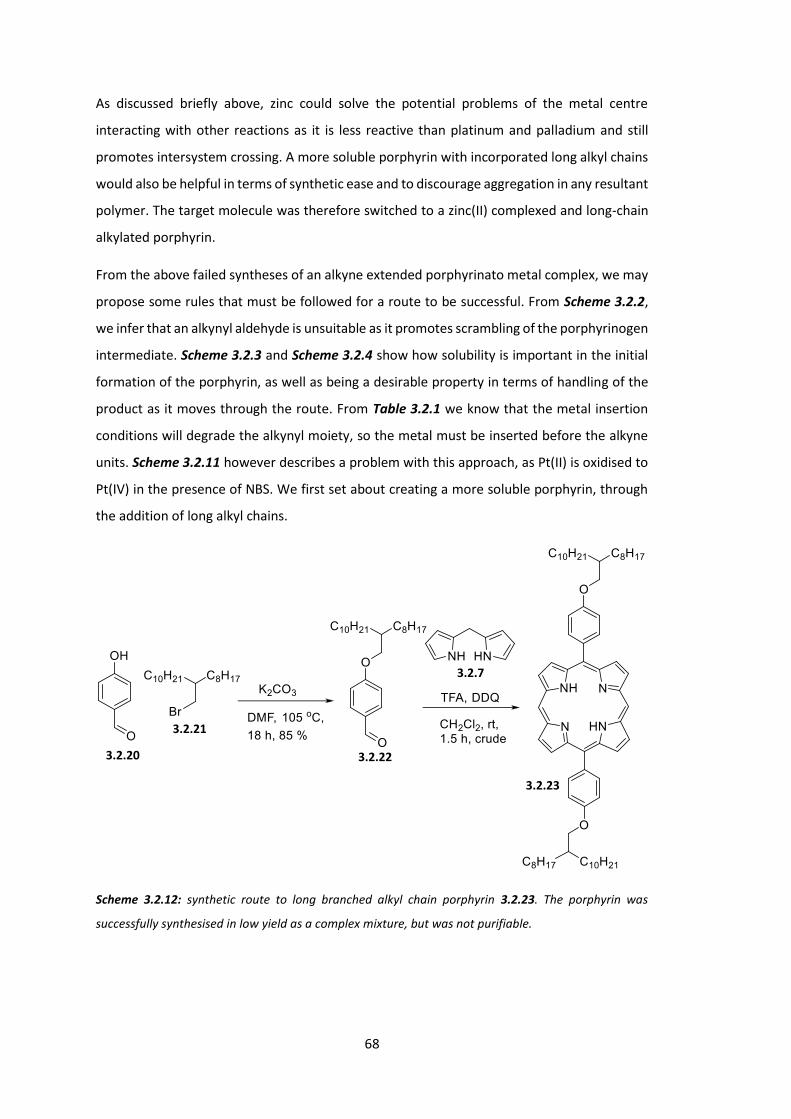
68
As discussed briefly above, zinc could solve the potential problems of the metal centre
interacting with other reactions as it is less reactive than platinum and palladium and still
promotes intersystem crossing. A more soluble porphyrin with incorporated long alkyl chains
would also be helpful in terms of synthetic ease and to discourage aggregation in any resultant
polymer. The target molecule was therefore switched to a zinc(II) complexed and long-chain
alkylated porphyrin.
From the above failed syntheses of an alkyne extended porphyrinato metal complex, we may
propose some rules that must be followed for a route to be successful. From Scheme 3.2.2,
we infer that an alkynyl aldehyde is unsuitable as it promotes scrambling of the porphyrinogen
intermediate. Scheme 3.2.3 and Scheme 3.2.4 show how solubility is important in the initial
formation of the porphyrin, as well as being a desirable property in terms of handling of the
product as it moves through the route. From Table 3.2.1 we know that the metal insertion
conditions will degrade the alkynyl moiety, so the metal must be inserted before the alkyne
units. Scheme 3.2.11 however describes a problem with this approach, as Pt(II) is oxidised to
Pt(IV) in the presence of NBS. We first set about creating a more soluble porphyrin, through
the addition of long alkyl chains.
Scheme 3.2.12: synthetic route to long branched alkyl chain porphyrin 3.2.23. The porphyrin was
successfully synthesised in low yield as a complex mixture, but was not purifiable.
3.2.20
3.2.21
3.2.22
3.2.7
3.2.23
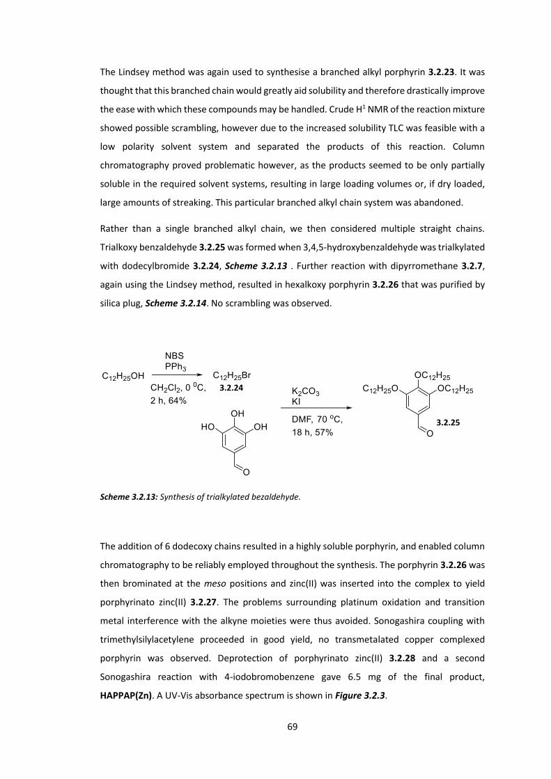
69
The Lindsey method was again used to synthesise a branched alkyl porphyrin 3.2.23. It was
thought that this branched chain would greatly aid solubility and therefore drastically improve
the ease with which these compounds may be handled. Crude H1 NMR of the reaction mixture
showed possible scrambling, however due to the increased solubility TLC was feasible with a
low polarity solvent system and separated the products of this reaction. Column
chromatography proved problematic however, as the products seemed to be only partially
soluble in the required solvent systems, resulting in large loading volumes or, if dry loaded,
large amounts of streaking. This particular branched alkyl chain system was abandoned.
Rather than a single branched alkyl chain, we then considered multiple straight chains.
Trialkoxy benzaldehyde 3.2.25 was formed when 3,4,5-hydroxybenzaldehyde was trialkylated
with dodecylbromide 3.2.24, Scheme 3.2.13 . Further reaction with dipyrromethane 3.2.7,
again using the Lindsey method, resulted in hexalkoxy porphyrin 3.2.26 that was purified by
silica plug, Scheme 3.2.14. No scrambling was observed.
Scheme 3.2.13: Synthesis of trialkylated bezaldehyde.
The addition of 6 dodecoxy chains resulted in a highly soluble porphyrin, and enabled column
chromatography to be reliably employed throughout the synthesis. The porphyrin 3.2.26 was
then brominated at the meso positions and zinc(II) was inserted into the complex to yield
porphyrinato zinc(II) 3.2.27. The problems surrounding platinum oxidation and transition
metal interference with the alkyne moieties were thus avoided. Sonogashira coupling with
trimethylsilylacetylene proceeded in good yield, no transmetalated copper complexed
porphyrin was observed. Deprotection of porphyrinato zinc(II) 3.2.28 and a second
Sonogashira reaction with 4-iodobromobenzene gave 6.5 mg of the final product,
HAPPAP(Zn). A UV-Vis absorbance spectrum is shown in Figure 3.2.3.
3.2.24
3.2.25

70
Scheme 3.2.14: Synthesis of HAPPAP(Zn).
3.2.7
3.2.25
3.2.26 3.2.27
3.2.28 3.2.29
HAPPAP(Zn)

71
300 400 500 600 700
0.0
0.2
0.4
0.6
0.8
1.0
1.2
Nor
mal
ised
Abs
orba
nce
Wavelength / nm
Figure 3.2.3: Absorbance spectrum of HAPPAP(Zn) (top) and absorbance (circles) and emission (solid)
spectra of F8BT. F8BT data taken from Chappell et al.103
For HAPPAP(Zn) to be successfully incorporated into a polymer and the system be capable of
TTA upconversion the emission and absorbance profiles of both constituent parts must be
compatible. The Q band of HAPPAP(Zn) is the lowest energy absorbance band of the system;
photons with wavelength of 640 nm may be absorbed. For TTA upconversion to occur, the
exciton formed from absorption of a 640 nm photon (initially a singlet that then undergoes
ISC to a lower lying triplet state on the porphyrin) must be transferred to the polymer
HAPPAP(Zn)
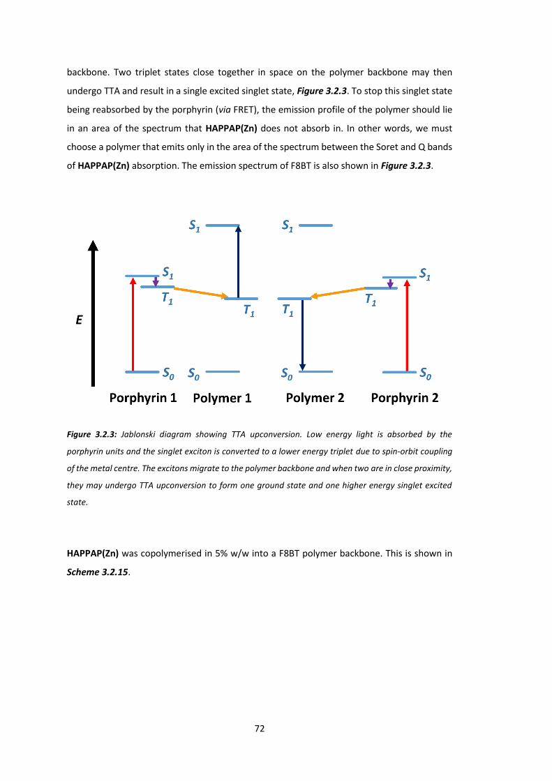
72
backbone. Two triplet states close together in space on the polymer backbone may then
undergo TTA and result in a single excited singlet state, Figure 3.2.3. To stop this singlet state
being reabsorbed by the porphyrin (via FRET), the emission profile of the polymer should lie
in an area of the spectrum that HAPPAP(Zn) does not absorb in. In other words, we must
choose a polymer that emits only in the area of the spectrum between the Soret and Q bands
of HAPPAP(Zn) absorption. The emission spectrum of F8BT is also shown in Figure 3.2.3.
Figure 3.2.3: Jablonski diagram showing TTA upconversion. Low energy light is absorbed by the
porphyrin units and the singlet exciton is converted to a lower energy triplet due to spin-orbit coupling
of the metal centre. The excitons migrate to the polymer backbone and when two are in close proximity,
they may undergo TTA upconversion to form one ground state and one higher energy singlet excited
state.
HAPPAP(Zn) was copolymerised in 5% w/w into a F8BT polymer backbone. This is shown in
Scheme 3.2.15.
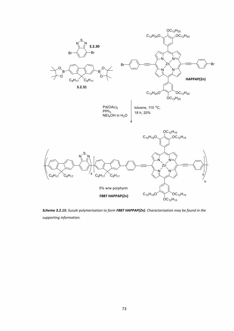
73
Scheme 3.2.15: Suzuki polymerisation to form F8BT HAPPAP(Zn). Characterisation may be found in the
supporting information.
F8BT HAPPAP(Zn)
3.2.31
3.2.30
HAPPAP(Zn)
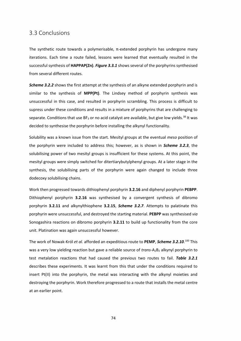
74
3.3 Conclusions
The synthetic route towards a polymerisable, π-extended porphyrin has undergone many
iterations. Each time a route failed, lessons were learned that eventually resulted in the
successful synthesis of HAPPAP(Zn). Figure 3.3.1 shows several of the porphyrins synthesised
from several different routes.
Scheme 3.2.2 shows the first attempt at the synthesis of an alkyne extended porphyrin and is
similar to the synthesis of MPP(Pt). The Lindsey method of porphyrin synthesis was
unsuccessful in this case, and resulted in porphyrin scrambling. This process is difficult to
supress under these conditions and results in a mixture of porphyrins that are challenging to
separate. Conditions that use BF3 or no acid catalyst are available, but give low yields.38 It was
decided to synthesise the porphyrin before installing the alkynyl functionality.
Solubility was a known issue from the start. Mesityl groups at the eventual meso position of
the porphyrin were included to address this; however, as is shown in Scheme 3.2.3, the
solubilising power of two mesityl groups is insufficient for these systems. At this point, the
mesityl groups were simply switched for ditertiarybutylphenyl groups. At a later stage in the
synthesis, the solubilising parts of the porphyrin were again changed to include three
dodecoxy solubilising chains.
Work then progressed towards dithiophenyl porphyrin 3.2.16 and diphenyl porphyrin PEBPP.
Dithiophenyl porphyrin 3.2.16 was synthesised by a convergent synthesis of dibromo
porphyrin 3.2.11 and alkynylthiophene 3.2.15, Scheme 3.2.7. Attempts to palatinate this
porphyrin were unsuccessful, and destroyed the starting material. PEBPP was synthesised via
Sonogashira reactions on dibromo porphyrin 3.2.11 to build up functionality from the core
unit. Platination was again unsuccessful however.
The work of Nowak-Król et al. afforded an expeditious route to PEMP, Scheme 3.2.10.100 This
was a very low yielding reaction but gave a reliable source of trans-A2B2 alkynyl porphyrin to
test metalation reactions that had caused the previous two routes to fail. Table 3.2.1
describes these experiments. It was learnt from this that under the conditions required to
insert Pt(II) into the porphyrin, the metal was interacting with the alkynyl moieties and
destroying the porphyrin. Work therefore progressed to a route that installs the metal centre
at an earlier point.

75
Figure 3.3.1: Selection of porphyrins synthesised and isolated.
HAPPAP(Zn)
3.2.18
PEMP
PEBPP
3.2.16 3.2.11
76
Pt(II) coordinated porphyrin 3.2.18 was prepared by reaction of PtCl2 and porphyrin 3.2.11,
Scheme 3.2.11. Meso bromination using NBS was attempted, but resulted only in bromination
of the platinum centre (Pt(II) oxidised to Pt(IV)). This result was not anticipated or desired, but
is perhaps interesting from a scientific point of view.
From these unsuccessful routes, four ‘rules’ may be specified; the aldehyde in the initial
porphyrin synthesis cannot be alkyne 3.2.3; the porphyrin must contain sufficiently
solubilising moieties; platinum (and palladium) insertion is not possible on alkyne containing
porphyrins; Pt(II) is oxidised to Pt(IV) under standard meso bromination conditions. With these
rules in mind, a new route was proposed, Scheme 3.2.14. Alkyne units were installed after
porphyrin formation to avoid scrambling, and six dodecoxy chains are present on the
porphyrin which impart solubility to the system. The problems surrounding platinum insertion
and metal-coordinated porphyrin bromination were mitigated by changing the metal to zinc.
HAPPAP(Zn) was prepared by this route and was successfully copolymerised with F8BT
monomers to create a polymer with 5% w/w alkyne-extended porphyrin bound covalently in
the main polymer backbone.
F8BT HAPPAP(Zn) 5 is currently undergoing physical testing. Some interesting results have
been obtained, however this is not yet complete and beyond the scope of this body of work.

77

78
Chapter 4: Reducing the Singlet-Triplet
Energy Gap: Donor-Orthogonal
Acceptor Polymers
4.1 Introduction
Fluorene is well known as a monomer in many polymeric systems, as shown in previous
chapters. Spirobifluorenes, as they contain a fluorene unit, may be subjected to the same
previously studied chemistry with regards to polymerisations and synthesis, and will be
comparable in terms of energy levels and mobilities (at least for orbitals that are on the
backbone fluorene). The addition of another fluorene unit via the crucial spiro linker allows
for additional moieties to be introduced orthogonally to the main polymer chain. It is this
orthogonality that gives rise to the unique energy level systems that form the basis of this
chapter. A comparison of the structures of fluorene and spirobifluorene is shown in Figure
4.1.1.
Figure 4.1.1: Fluorene with selected atom numbers (left) and structure of spirobifluorene (middle) with
forced perspective (right). Fluorene is normally polymerised through the 2 and 7 positions and alkylated
on the 9 position.
As discussed in chapter 1, the population of non-emissive triplet states is a huge contributor
to the reduction in efficiency of all organic semiconducting devices. Eliminating (or utilising)
these loss processes is vital to organic electronic devices becoming competitive in the global
marketplace.104 This requires the careful control of energy levels.

79
The bandgap of an organic semiconductor has been well studied across many systems and can
be manipulated by synthetic design. From Figure 4.1.2, we may visualise this control as
moving all levels except the ground state (S0) up (increase bandgap) or down (decrease
bandgap) in energy. More subtle control over the individual excited states relative to each
other is more challenging however.
Figure 4.1.2: Generalised Jablonski diagram of an organic semiconductor.
One reason this control is especially desirable is for the development of thermally activated
delayed fluorescence (TADF) materials. By creating a system in which the first excited singlet
and first excited triplet states are the same or close to each other in energy (0.2 ≥ ΔEST ≥ 0 eV,
from Figure 4.1.2), the previously spin forbidden transition of an exciton moving from singlet
to triplet (and vice versa) becomes possible. The transition is of course still formally forbidden,
however since the levels are so close in energy, the activation energy to surmount this
transition becomes comparable to kBT at 298 K. In other words, by exhibiting control over ΔEST
so as to make it close to 0, we observe delayed fluorescence that is dependent on
temperature.105-106 For a review of TADF materials, see Yang et al.107
The key process of a TADF material is reverse intersystem crossing (RISC) from T1 → S1. The
rate of RISC is related to ΔEST and temperature:
𝑘𝑅𝐼𝑆𝐶 ∝ 𝑒𝑥𝑝−𝛥𝐸𝑆𝑇𝑘𝐵𝑇
Since ΔEST is generally large (0.5 – 1.0 eV) for the majority of organic semiconducting systems,
the rate of RISC and therefore TADF is negligible. When we decrease ΔEST however, kRISC
increases and we eventually reach a point where the population of the first excited singlet is

80
substantially boosted from the first excited triplet, thereby resulting in a system that may emit
from S1 regardless of the original spin of the initially formed exciton.
This degree of energy level control resulting in a high performance device was first reported
by Adachi et al. in 2011 where a small molecule was incorporated into an OLED that was
shown to undergo TADF.108 This work was expanded upon in 2012 when a high performance
OLED was reported by the same group.105 TADF was achieved by separating the HOMO and
LUMO through a twist in the molecular structure, decreasing the exchange energy between
the two and thereby decreasing ΔEST, Figure 4.1.3.
Figure 4.1.3: Twisted D-A general structure (top) and TADF capable molecule 2CzPn (bottom left) with
calculated HOMO (bottom middle) and LUMO (bottom right).
It has not been more challenging to exhibit this level of control over ΔEST in polymers
however.104 In an organic semiconducting system, the frontier molecular orbitals are
dominated by π-π* transitions. In polymers both HOMO and LUMO lie on the polymer
backbone and separation of the two becomes unfeasible. Köhler et al. studied a series of
semiconducting polymers and plotted their measured singlet and triplet energy levels, their
graph is shown in Figure 4.1.4.109 As S1 moves further from the ground state S0, it is seen that
T1 moves a roughly equivalent amount. This has the result that ΔEST is constantly close to 0.7
eV for all polymers. From related papers;
“For the all-organic polymers, we find the T1 state to be at a constant separation
of 0.7±0.1 eV below the singlet S1 state. It is not possible to change this singlet–

81
triplet splitting by altering the size or the charge-transfer character of the
polymer repeat unit or by changing the electron delocalization along the
polymer backbone.”110
“For conjugated polymers … the S1-T1 gap is experimentally found to be about
0.7 eV, virtually independent of chemical structure.”104
Figure 4.1.4: Relationship between singlet energy and triplet energy of organic polymers. Reported by
Köhler et al.109
Köhler’s conclusion that ΔEST may not be largely affected in polymers holds true for all
standard organic semiconducting polymers, where the HOMO and LUMO must both lie along
the backbone because of the extended π-structure. This is true even for donor-acceptor (DA)
polymers, where orbitals are somewhat localised to different parts of the polymer backbone.
Polymeric systems that show some degree of TADF have been reported however. In 2015
Fraser et al. and Nikolaenko et al. separately reported non-conjugated polymers that contain
small molecules capable of TADF as end-capping groups or as part of the polymer chain, Figure
4.1.5 and Figure 4.1.6.111-112
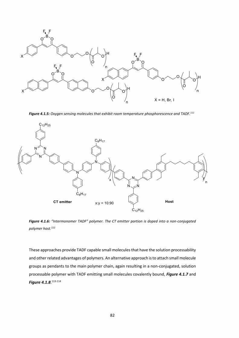
82
Figure 4.1.5: Oxygen sensing molecules that exhibit room temperature phosphorescence and TADF.111
Figure 4.1.6: “Intermonomer TADF” polymer. The CT emitter portion is doped into a non-conjugated
polymer host.112
These approaches provide TADF capable small molecules that have the solution processability
and other related advantages of polymers. An alternative approach is to attach small molecule
groups as pendants to the main polymer chain, again resulting in a non-conjugated, solution
processable polymer with TADF emitting small molecules covalently bound, Figure 4.1.7 and
Figure 4.1.8.113-114
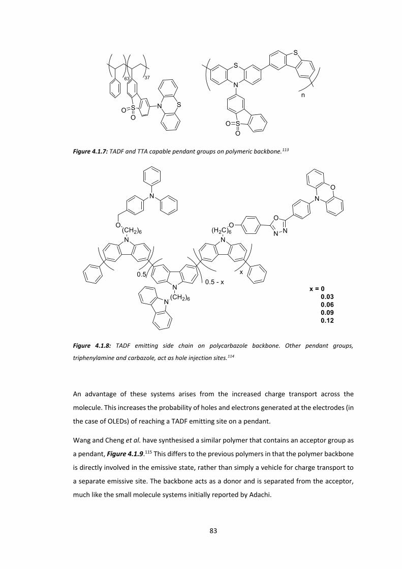
83
Figure 4.1.7: TADF and TTA capable pendant groups on polymeric backbone.113
Figure 4.1.8: TADF emitting side chain on polycarbazole backbone. Other pendant groups,
triphenylamine and carbazole, act as hole injection sites.114
An advantage of these systems arises from the increased charge transport across the
molecule. This increases the probability of holes and electrons generated at the electrodes (in
the case of OLEDs) of reaching a TADF emitting site on a pendant.
Wang and Cheng et al. have synthesised a similar polymer that contains an acceptor group as
a pendant, Figure 4.1.9.115 This differs to the previous polymers in that the polymer backbone
is directly involved in the emissive state, rather than simply a vehicle for charge transport to
a separate emissive site. The backbone acts as a donor and is separated from the acceptor,
much like the small molecule systems initially reported by Adachi.
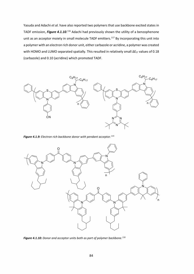
84
Yasuda and Adachi et al. have also reported two polymers that use backbone excited states in
TADF emission, Figure 4.1.10.116 Adachi had previously shown the utility of a benzophenone
unit as an acceptor moiety in small molecule TADF emitters.117 By incorporating this unit into
a polymer with an electron rich donor unit, either carbazole or acridine, a polymer was created
with HOMO and LUMO separated spatially. This resulted in relatively small ΔEST values of 0.18
(carbazole) and 0.10 (acridine) which promoted TADF.
Figure 4.1.9: Electron rich backbone donor with pendant acceptor.115
Figure 4.1.10: Donor and acceptor units both as part of polymer backbone.116

85
The addition of a ketone moiety in these polymers is an important difference. Where most
polymers with aromatic groups have a π→π* transition to create an excited state, the
orthogonal electrons in a ketone are not part of an aromatic system and undergo a n→π*
transition upon electronic excitation. It is the orthogonality of the ketone ground state
electrons relative to the polymer backbone that leads to separation of HOMO and LUMO and
therefore a reduction in ΔEST. This means for this type of system, the ketone is vital. As ketones
are often not desirable for semiconducting applications (they act as charge traps), this system
has considerable limitations.
Monkman et al. and Ding and Wang et al. have independently synthesised polymers that
separate the HOMO and LUMO via a spiro linkage, Figure 4.1.11 and Figure 4.1.12.118-119
Monkman observes TADF and attributes it to emission from a 1CT state that is populated
indirectly from TTA upconversion. This is a different version of delayed fluorescence from
those based on the minimisation of ΔEST, known as p-type delayed fluorescence (direct
population of the first excited singlet from the first excited triplet using thermal energy is
known as e-type delayed fluorescence). The polymers synthesised in this chapter are based
on e-type delayed fluorescence, but the manipulation of energy levels is important for both
types.
Figure 4.1.11: Spiro linked TADF polymer. Polyfluorene backbone acts as acceptor and orthogonal
fluorene unit acts as donor. TADF occurs in this polymer as a result of population of 1CT state from TTA
from backbone triplet state.120
The spiro twist separates MOs but also allows enough overlap that energy transfer through
the spiro linkage is fast if orbitals are close in energy. These polymers have a very low lying 3(π-π*) state (described by Monkman as a 3LE state) on the polymer backbone which
undergoes TTA to repopulate higher energy states. The spiro link is a good way of introducing
orthogonality to a molecule as the two fluorene units are fixed 90° relative to each other.

86
Figure 4.1.12: Spiro linked polymer. Donor units are linked through a spiro moiety to the polyfluorene
backbone which acts as an acceptor. TADF is not reported for these polymers.119
The precedent for TADF in polymers is limited to these cases however, and none show
emission as a result of only TADF, but rather observe that RISC is an allowed process. A specific
example is also not as useful to the scientific community as a standard tuneable design would
be. The scope for new polymeric systems where ΔEST may be tuned is therefore large.
We know from Adachi’s work on small molecule systems that reduction of ΔEST may be
achieved through separation of the HOMO and LUMO orbitals.117 This is also observed in the
polymeric systems. In each case, the HOMO and LUMO are separated in space. This is achieved
either by using a small molecule covalently attached to the polymer backbone,111-113 or by
creating large twists in the polymer backbone that break conjugation.114-115
Figure 4.1.13 describes a conjugated polyfluorene with spiro-linked electron poor fluorene
groups. An electron poor orthogonal group (as opposed to electron rich seen in Figure 4.1.11
and Figure 4.1.12) creates a classic donor-acceptor copolymer, but one where the acceptor is
orthogonal to the polymer backbone. Figure 4.1.14 shows how this affects the distributions
of the frontier molecular orbitals and relative energy levels.
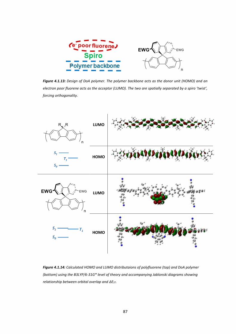
87
Figure 4.1.13: Design of DoA polymer. The polymer backbone acts as the donor unit (HOMO) and an
electron poor fluorene acts as the acceptor (LUMO). The two are spatially separated by a spiro ‘twist’,
forcing orthogonality.
LUMO
HOMO
LUMO
HOMO
Figure 4.1.14: Calculated HOMO and LUMO distributaions of polyfluorene (top) and DoA polymer
(bottom) using the B3LYP/6-31G* level of theory and accompanying Jablonski diagrams showing
relationship between orbital overlap and ΔEST.

88
The LUMO of polyfluorene overlaps the HOMO as both lie across the backbone, as is the case
for almost all conjugated polymers. The addition of electron poor orthogonal groups of the
donor orthogonal-acceptor (DoA) polymer forces the LUMO onto a spatially distinct part of
the polymer. It was hypothesised that this would have the result of a decreased ΔEST while
maintaining the beneficial properties of polyfluorene, such as processibility and flexibility.
The work described in this chapter has been published.121
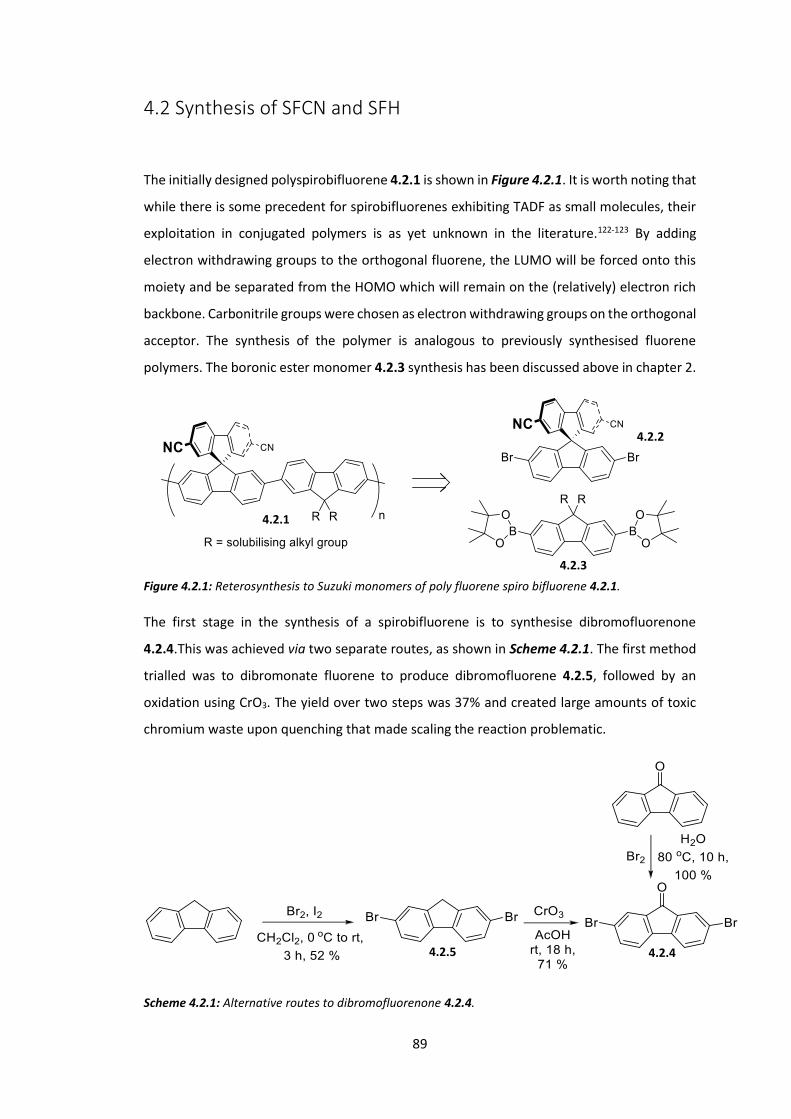
89
4.2 Synthesis of SFCN and SFH
The initially designed polyspirobifluorene 4.2.1 is shown in Figure 4.2.1. It is worth noting that
while there is some precedent for spirobifluorenes exhibiting TADF as small molecules, their
exploitation in conjugated polymers is as yet unknown in the literature.122-123 By adding
electron withdrawing groups to the orthogonal fluorene, the LUMO will be forced onto this
moiety and be separated from the HOMO which will remain on the (relatively) electron rich
backbone. Carbonitrile groups were chosen as electron withdrawing groups on the orthogonal
acceptor. The synthesis of the polymer is analogous to previously synthesised fluorene
polymers. The boronic ester monomer 4.2.3 synthesis has been discussed above in chapter 2.
Figure 4.2.1: Reterosynthesis to Suzuki monomers of poly fluorene spiro bifluorene 4.2.1.
The first stage in the synthesis of a spirobifluorene is to synthesise dibromofluorenone
4.2.4.This was achieved via two separate routes, as shown in Scheme 4.2.1. The first method
trialled was to dibromonate fluorene to produce dibromofluorene 4.2.5, followed by an
oxidation using CrO3. The yield over two steps was 37% and created large amounts of toxic
chromium waste upon quenching that made scaling the reaction problematic.
Scheme 4.2.1: Alternative routes to dibromofluorenone 4.2.4.
4.2.5 4.2.4
4.2.1
4.2.2
4.2.3
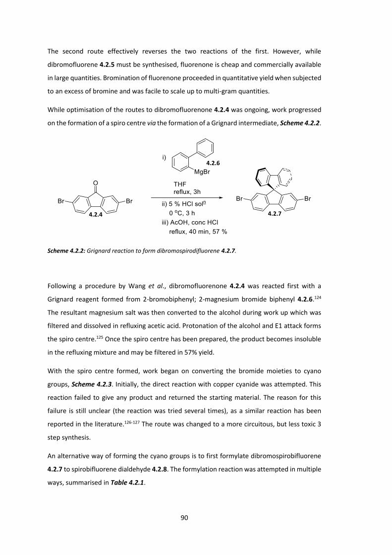
90
The second route effectively reverses the two reactions of the first. However, while
dibromofluorene 4.2.5 must be synthesised, fluorenone is cheap and commercially available
in large quantities. Bromination of fluorenone proceeded in quantitative yield when subjected
to an excess of bromine and was facile to scale up to multi-gram quantities.
While optimisation of the routes to dibromofluorenone 4.2.4 was ongoing, work progressed
on the formation of a spiro centre via the formation of a Grignard intermediate, Scheme 4.2.2.
Scheme 4.2.2: Grignard reaction to form dibromospirodifluorene 4.2.7.
Following a procedure by Wang et al., dibromofluorenone 4.2.4 was reacted first with a
Grignard reagent formed from 2-bromobiphenyl; 2-magnesium bromide biphenyl 4.2.6.124
The resultant magnesium salt was then converted to the alcohol during work up which was
filtered and dissolved in refluxing acetic acid. Protonation of the alcohol and E1 attack forms
the spiro centre.125 Once the spiro centre has been prepared, the product becomes insoluble
in the refluxing mixture and may be filtered in 57% yield.
With the spiro centre formed, work began on converting the bromide moieties to cyano
groups, Scheme 4.2.3. Initially, the direct reaction with copper cyanide was attempted. This
reaction failed to give any product and returned the starting material. The reason for this
failure is still unclear (the reaction was tried several times), as a similar reaction has been
reported in the literature.126-127 The route was changed to a more circuitous, but less toxic 3
step synthesis.
An alternative way of forming the cyano groups is to first formylate dibromospirobifluorene
4.2.7 to spirobifluorene dialdehyde 4.2.8. The formylation reaction was attempted in multiple
ways, summarised in Table 4.2.1.
4.2.4
4.2.6
4.2.7

91
Scheme 4.2.3: Synthesis of dicyanospirobifluorene 4.2.9.
Carbocation Forming Reagent
Formylation Reagent
T / oC t / h Result
nBuLi DMF -78 to rt 1.5 No product obtained – debromination observed
Mg DMF Reflux 24 No reaction observed nBuLi N-formyl
piperidine -78 to rt 1.5 Product obtained – 39% yield
Table 4.2.1: Formylation conditions for dibromospirodifluorene 4.2.7.
Lithium-halogen exchange followed by addition of DMF was first investigated. No product was
obtained and the starting material was completely consumed. Mass spectrometry showed
loss of bromine moieties (i.e. naked spirobifluorene). Milder conditions were also trialled;
formation of a di-Grignard reagent followed by addition of DMF. No reaction was observed in
this instance as the Grignard reagent failed to form. nBuLi therefore was deemed strong
enough to initiate metal-halogen exchange (since starting material had been consumed)
whereas Mg was not. By substituting the formylation reagent it was thought that the metal-
halogen exchange with nBuLi could be more successful. Replacement of DMF as formylation
reagent for N-formyl piperidine, which has been shown in some cases to give more favourable
results, was then attempted.128 This reaction was successful and gave the desired product in
39% yield. Stirring the product in ammonium hydroxide solution with iodine gave
dicyanospirobifluorene 4.2.9 in quantitive yield.
Dibromination then proceeded in an analogous reaction to the dibromination of fluorenone
by molecular bromine. The isolated yield of the desired spiro monomer 4.2.2 was low, with
the main issue surrounding this final reaction before polymerisation being under-
bromination. The monobromide side product is difficult to remove by chromatography and
4.2.7
4.2.8
4.2.9
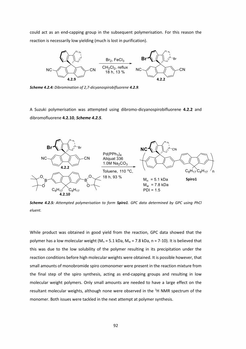
92
could act as an end-capping group in the subsequent polymerisation. For this reason the
reaction is necessarily low yielding (much is lost in purification).
Scheme 4.2.4: Dibromination of 2,7-dicyanospirobifluorene 4.2.9.
A Suzuki polymerisation was attempted using dibromo-dicyanospirobifluorene 4.2.2 and
dibromofluorene 4.2.10, Scheme 4.2.5.
Scheme 4.2.5: Attempted polymerisation to form Spiro1. GPC data determined by GPC using PhCl
eluent.
While product was obtained in good yield from the reaction, GPC data showed that the
polymer has a low molecular weight (Mn = 5.1 kDa, Mw = 7.8 kDa, n = 7-10). It is believed that
this was due to the low solubility of the polymer resulting in its precipitation under the
reaction conditions before high molecular weights were obtained. It is possible however, that
small amounts of monobromide spiro comonomer were present in the reaction mixture from
the final step of the spiro synthesis, acting as end-capping groups and resulting in low
molecular weight polymers. Only small amounts are needed to have a large effect on the
resultant molecular weights, although none were observed in the 1H NMR spectrum of the
monomer. Both issues were tackled in the next attempt at polymer synthesis.
4.2.9 4.2.2
4.2.2
4.2.10
Spiro1

93
To combat the probable solubility issue, the fluorene co-monomer was modified in an effort
to increase the solubility of the polymer as it is formed in reaction. This was achieved simply
by increasing the length of the alkyl chains, Scheme 4.2.6.
Scheme 4.2.6: Synthesis of hexadecyl alkylated fluorene boronic ester monomer 4.2.12.
A new route towards the spiro monomer was proposed that avoided the issue of
monobrominated side product in the final material (Scheme 4.2.7). Dibromofluoreneone was
again used in a Grignard reaction to form the spiro centre but with the modification of a
dimethyl biphenyl Grignard reagent. The benzylic moieties were then converted to cyano
groups through a three step synthesis.
By converting benzyl (as opposed to aryl bromide) groups to cyano groups the dibromide
moiety is installed early and left unchanged. Any monobromide end-capping groups are
therefore removed early in the synthesis.
4,4’-Dimethylbiphenyl is firstly monobrominated at the 2-position in quantitative yield to form
bromobiphenyl 4.2.13. An analogous Grignard reaction to Scheme 4.2.2 gave spirobifluorene
4.2.14 in good yield. Conversion of the benzylic positions to carbonitrile groups was achieved
through bromination followed by conversion to a dialdehyde and finally the dicyano monomer
4.2.9.
A downside to this route is the use of toxic CCl4 as solvent in the bromination step; it is
employed so as to avoid radical quenching. A similar reaction has since been successful within
the group using chloroform as solvent, it is thought this would also be the case here although
it was never trialled for this particular route.
4.2.5
4.2.11
4.2.12

94
Scheme 4.2.7: Synthesis of spiro monomer 4.2.9 via 2-bromo-4,4’-dimethylbiphenyl 4.2.13.
The spiro and hexadecyl monomers 4.2.9 and 4.2.12 were then polymerised as in Scheme
4.2.8.
Scheme 4.2.8: Suzuki polymerisation to form SFCN.
4.2.4
4.2.9
4.2.13
4.2.14
4.2.15 4.2.16

95
The molecular weight of this polymer was much improved compared to the octyl version,
spiro1. A reference polymer without the electron withdrawing cyano groups was also
prepared in order for electrochemical comparisons to be made; SFH, Scheme 4.2.9. The
synthetic method was identical to the synthesis of SFCN with the exception of the spiro
monomer (dibromospirobifluorene 4.2.7 was substituted). These two polymers were
analysed further at the University of Cambridge by Dr. Andrew Musser to elucidate the
complex energy level structure, this work is detailed below in section 4.4. Synthetic efforts at
this point moved onto the related polymers ASFCN and ASFH.
Scheme 4.2.9: Suzuki polymerisation to form SFH.
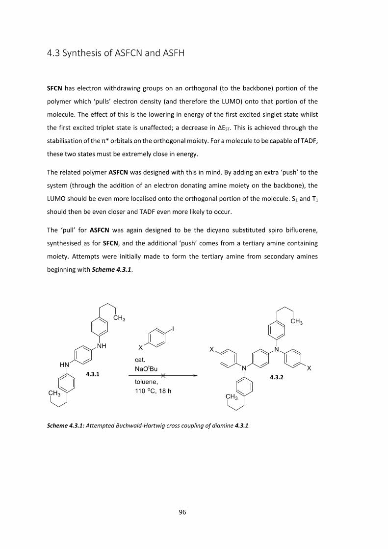
96
4.3 Synthesis of ASFCN and ASFH
SFCN has electron withdrawing groups on an orthogonal (to the backbone) portion of the
polymer which ‘pulls’ electron density (and therefore the LUMO) onto that portion of the
molecule. The effect of this is the lowering in energy of the first excited singlet state whilst
the first excited triplet state is unaffected; a decrease in ΔEST. This is achieved through the
stabilisation of the π* orbitals on the orthogonal moiety. For a molecule to be capable of TADF,
these two states must be extremely close in energy.
The related polymer ASFCN was designed with this in mind. By adding an extra ‘push’ to the
system (through the addition of an electron donating amine moiety on the backbone), the
LUMO should be even more localised onto the orthogonal portion of the molecule. S1 and T1
should then be even closer and TADF even more likely to occur.
The ‘pull’ for ASFCN was again designed to be the dicyano substituted spiro bifluorene,
synthesised as for SFCN, and the additional ‘push’ comes from a tertiary amine containing
moiety. Attempts were initially made to form the tertiary amine from secondary amines
beginning with Scheme 4.3.1.
Scheme 4.3.1: Attempted Buchwald-Hartwig cross coupling of diamine 4.3.1.
4.3.2 4.3.1
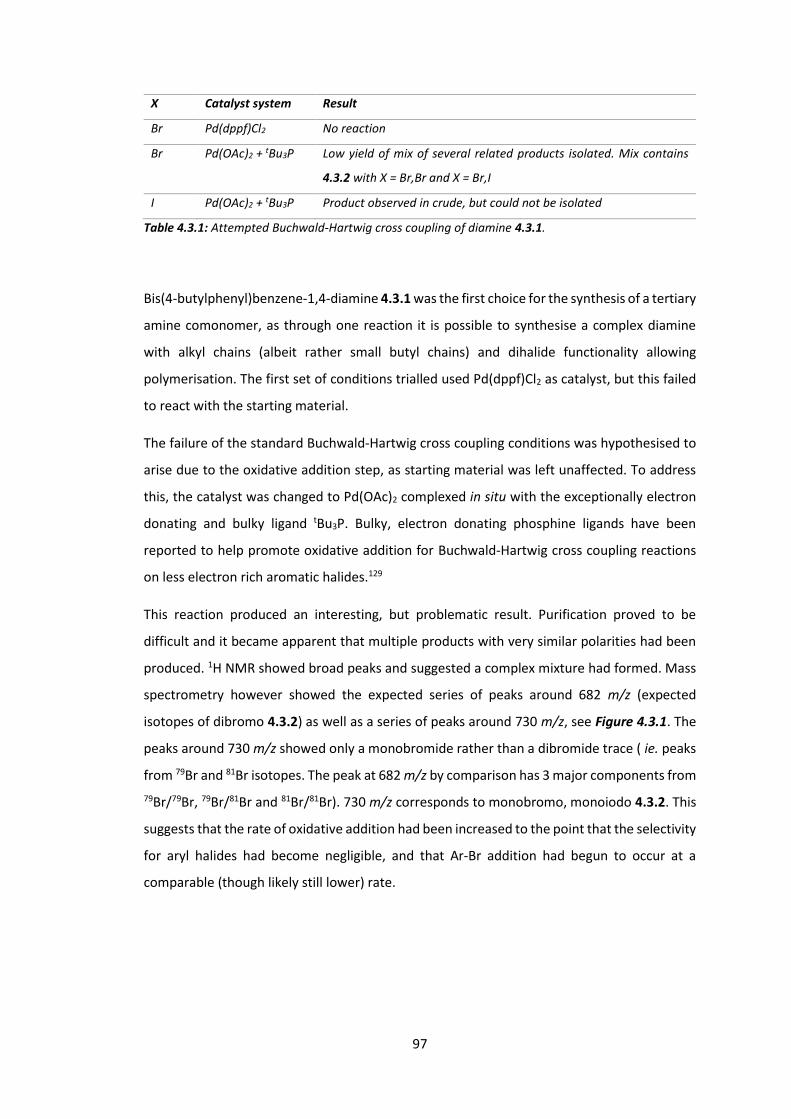
97
X Catalyst system Result
Br Pd(dppf)Cl2 No reaction
Br Pd(OAc)2 + tBu3P Low yield of mix of several related products isolated. Mix contains
4.3.2 with X = Br,Br and X = Br,I
I Pd(OAc)2 + tBu3P Product observed in crude, but could not be isolated
Table 4.3.1: Attempted Buchwald-Hartwig cross coupling of diamine 4.3.1.
Bis(4-butylphenyl)benzene-1,4-diamine 4.3.1 was the first choice for the synthesis of a tertiary
amine comonomer, as through one reaction it is possible to synthesise a complex diamine
with alkyl chains (albeit rather small butyl chains) and dihalide functionality allowing
polymerisation. The first set of conditions trialled used Pd(dppf)Cl2 as catalyst, but this failed
to react with the starting material.
The failure of the standard Buchwald-Hartwig cross coupling conditions was hypothesised to
arise due to the oxidative addition step, as starting material was left unaffected. To address
this, the catalyst was changed to Pd(OAc)2 complexed in situ with the exceptionally electron
donating and bulky ligand tBu3P. Bulky, electron donating phosphine ligands have been
reported to help promote oxidative addition for Buchwald-Hartwig cross coupling reactions
on less electron rich aromatic halides.129
This reaction produced an interesting, but problematic result. Purification proved to be
difficult and it became apparent that multiple products with very similar polarities had been
produced. 1H NMR showed broad peaks and suggested a complex mixture had formed. Mass
spectrometry however showed the expected series of peaks around 682 m/z (expected
isotopes of dibromo 4.3.2) as well as a series of peaks around 730 m/z, see Figure 4.3.1. The
peaks around 730 m/z showed only a monobromide rather than a dibromide trace ( ie. peaks
from 79Br and 81Br isotopes. The peak at 682 m/z by comparison has 3 major components from 79Br/79Br, 79Br/81Br and 81Br/81Br). 730 m/z corresponds to monobromo, monoiodo 4.3.2. This
suggests that the rate of oxidative addition had been increased to the point that the selectivity
for aryl halides had become negligible, and that Ar-Br addition had begun to occur at a
comparable (though likely still lower) rate.

98
Figure 4.3.1: CI+ mass spectrum of Buchwald-Hartwig product containing dibromo and monobromo
monoiodo diamine 4.3.2. R = 4-n-butylphenyl. Fragments have been shown as radicals for visualisation
purposes.
A Miyaura borylation was attempted on the mixture of products, as both bromo and iodo
moieties should react to form the same product, this reaction was done on a very small scale
however and didn’t give sufficient product to attempt a polymerisation. The Buchwald-
Hartwig reaction was repeated, with the exception of using 1,4-diiodobenzene to eliminate
the mixture of products obtained previously. It is believed the reaction was successful based
on analysis of the crude 1H NMR, however purification proved difficult and no pure product
was isolated. Due to the problems associated with this route and the fairly high cost of the
diamine starting material, focus was shifted to an alternative molecule.
99
Scheme 4.3.2: Attempted synthesis of spirobifluorenediamine 4.3.6.
Installation of a tertiary amine unit into the final polymer backbone can be achieved in two
ways; copolymerising a tertiary amine comonomer with the spiro monomer 4.3.4, or by
converting spiro monomer 4.3.4 into a tertiary amine in its own right. This second method has
the additional advantages of increased electron density near the orthogonal acceptor as well
as the possibility of homopolymerisation using a Yamamoto reaction. This would eliminate
the need to synthesise a comonomer, as target spirodiamine 4.3.6 contains an orthogonal
acceptor, electron rich tertiary amine moieties and solubilising alkyl chains in a single
monomer. Of course, the polymerisation conditions could also be changed to include a
comonomer to affect the resultant polymer in various ways if desired.
An Ullmann amine synthesis formed heptylphenylaniline 4.3.3. This secondary amine and
previously formed spiro monomer 4.3.4 were then subjected to the enhanced Buchwald-
Hartwig conditions from Table 4.3.1 in an effort to form ditertiary amine 4.3.5. This reaction
was unsuccessful however, and returned both starting materials unreacted.
Due to the difficulties encountered in the synthesis of a bespoke tertiary amine from a
secondary amine, focus shifted onto routes that start with a preformed tertiary amine;
triphenylamine. Scheme 4.3.3 shows the various routes that were trialled (grey) before the
successful route (black) was found. Discussion focusses on the left, middle then right
branches.
4.3.6
4.3.3
4.3.2
4.3.4
4.3.5

100
Monobromination of triphenylamine proceeded in good yield. Bromotriphenylamine 4.3.8
contained a bromide handle which could be used to install the necessary alkyl groups to aid
in solubility of the desired polymer. Treatment with nBuLi and subsequently with a
bromoalkane however yielded only the butylated product, not the desired long alkyl chain
triphenylamine 4.3.9, see Table 4.3.2. This suggests the SN2 step is much faster for the BuBr
side product than it is for alkyl bromide 4.3.15. A more bulky alkyl lithium reagent and a less
bulky alkylbromide were therefore substituted: the reaction was tried again with tBuLi and
C16H33Br. This reaction failed to yield significant amounts of product however and returned
mostly starting material. This was surprising, as tBuLi is a very strong lithiating reagent, it
seems likely that the reaction failed due to perhaps water in the reaction vessel or degradation
of reagent. The reaction was not retried however, a Kumada coupling was attempted instead.
Reagents Conditions Result
4.3.15, nBuLi THF, -78 oC,
30 min
Butylphenyldiphenylamine formed
C16H33Br, tBuLi THF, -78 oC,
30 min
Starting material returned ~ 80%. Green
precipitate formed, mixture of products
4.3.15, Mg,
NiCl2(dppp)
THF, rt, 18 h Grignard reagent not substantially formed,
small (~ 15%) side product in NMR could be
product
4.3.15, Mg,
NiCl2(dppp)
Et2O, rt, 18 h Grignard reagent not substantially formed
4.3.15, Mg,
NiCl2(dppp)
Et2O, rt, 18 h
(repeat of
above)
Grignard reagent formed in low yeild, small
(~ 25%) side product in NMR could be
product
Table 4.3.2: Conditions trialled for alkylation of monobromotriphenylamine 4.3.8.
4.3.15
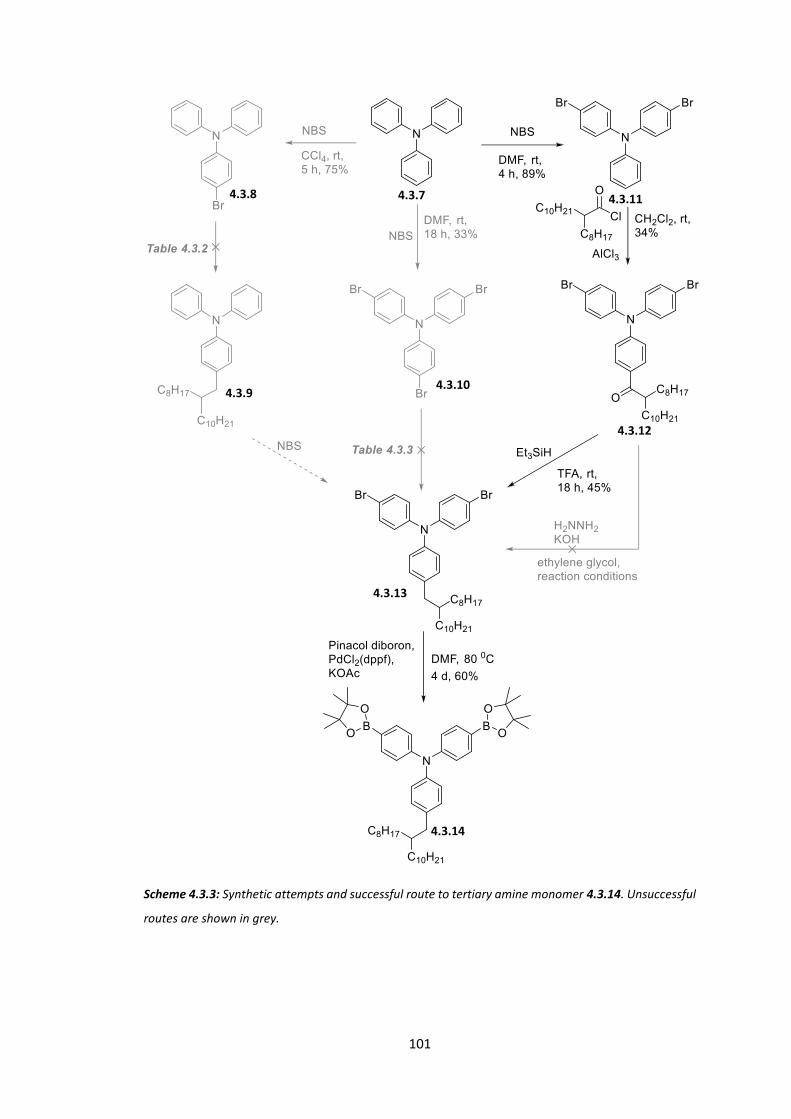
101
Scheme 4.3.3: Synthetic attempts and successful route to tertiary amine monomer 4.3.14. Unsuccessful
routes are shown in grey.
4.3.7 4.3.8
4.3.9
4.3.13
4.3.10
4.3.11
4.3.12
4.3.14

102
The Kumada cross-coupling reaction is useful in the formation of carbon-carbon bonds with
normally unreactive aryl halides.130 As this reactivity seemed to be problematic during the BuLi
reactions, this seemed like a good choice of reaction. Three attempts using Kumada conditions
were attempted, however each time it became apparent that the initial formation of the
Grignard reagent was problematic and proceeded, at best, in low yield.
While this work progressed, tri-4,4’,4’’-bromophenylamine 4.3.10 was also synthesised using
excess NBS on triphenylamine. Treatment of the tribrominated product 4.3.10 with one
equivalent of nBuLi and alkyl bromide again yielded the butyl product, and the Kumada
reaction also had similar results to those of the monobrominated reactions. These reactions
are summarised in Table 4.3.3.
Reagents Conditions Result
4.3.15, nBuLi THF, -78 oC, 30 min Butylphenyldibromophenylamine formed
4.3.15, Mg, NiCl2(dppp) Et2O, rt, 18 h Grignard reagent not substantially formed
Table 4.3.3: Conditions trialled for alkylation of tribromotriphenylamine 4.3.10.
Dibromination was then attempted using 2 equivalents of NBS to 1 of triphenylamine 4.3.7.
This route was not trialled earlier as it was thought that this reaction may produce a mixture
of mono, di, and tribrominated products; however the reaction progressed in excellent yield
and selectivity. A Friedel-Crafts acylation installed the troublesome alkyl chain as a ketone. A
first attempt to reduce the ketone using hydrazine (Wolff-Kishner reduction) was
unsuccessful, but alkylketotriphenylamine 4.3.12 was subsequently successfully reduced via
a reduction with triethylsilane to form alkyltriphenylamine 4.3.13. A Miyaura borolation then
yields the desired amine monomer 4.3.14.
The amine monomer 4.3.14 was then subjected to Suzuki polymerisation with spiro
monomers 4.3.4 and 4.3.16; Scheme 4.3.4 and Scheme 4.3.5.
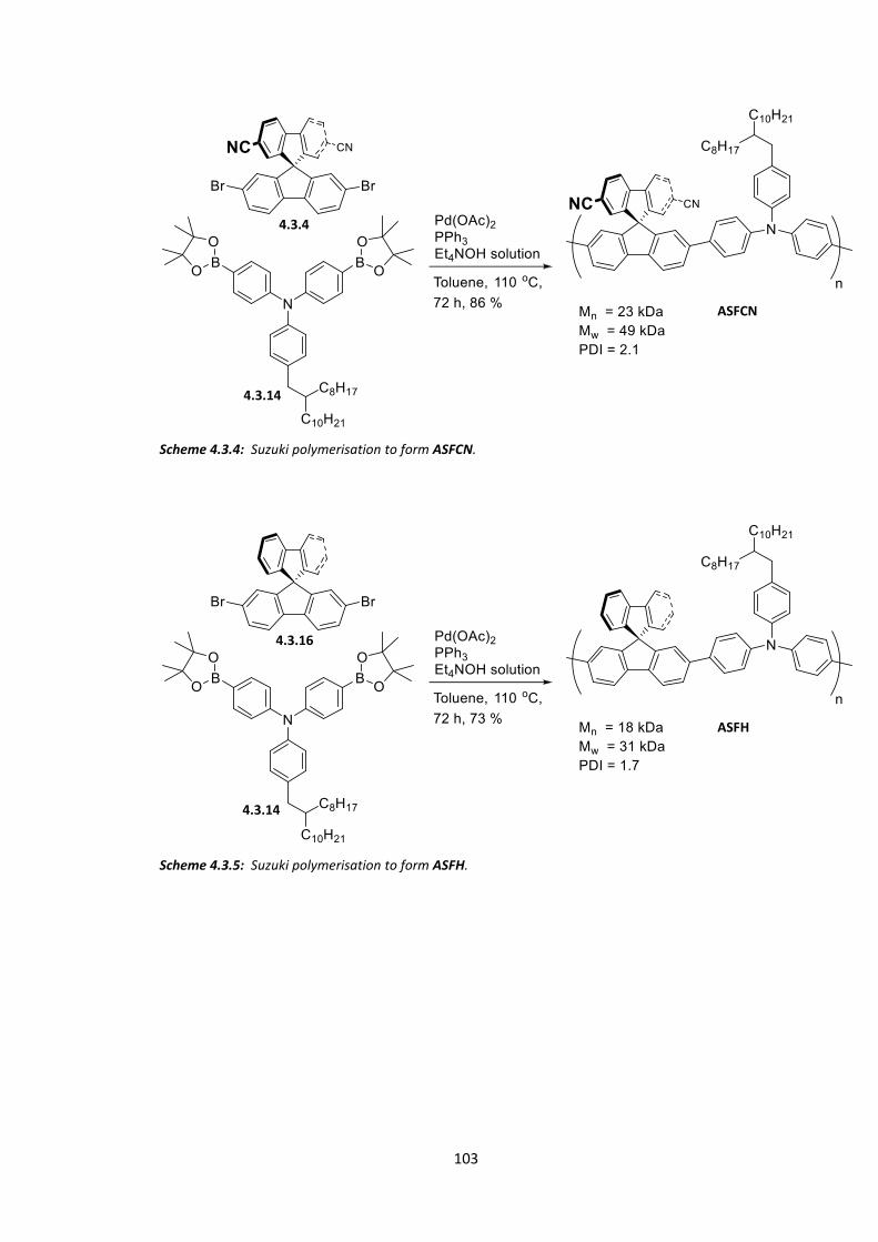
103
Scheme 4.3.4: Suzuki polymerisation to form ASFCN.
Scheme 4.3.5: Suzuki polymerisation to form ASFH.
4.3.4
4.3.14
4.3.16
4.3.14
ASFCN
ASFH

104
4.4 Physical and Optical Properties of SFH, SFCN, ASFH and
ASFCN
Once synthesised, each polymer was analysed first by GPC, UV-Vis and PL before being sent
to the University of Cambridge for more detailed analysis performed by Dr. Andrew Musser,
who appears as co-author on the resultant paper.121 The more advanced computational data
for these polymers was obtained by Dr. Jarvist Frost at Imperial College London.
Figure 4.4.1: UV-Vis absorption (shaded) and photoluminescence (unshaded) of polymer thin films.
Polymer Mna / kDa Mwa / kDa PDIa HOMOb / eV Egapc / eV εd / M-1cm-1
SFH 16 23 1.44 -5.77 2.97 16104
SFCN 20 29 1.45 -5.81 2.97 18384
ASFH 18 31 1.72 -5.37 2.89 11844
ASFCN 23 49 2.13 -5.42 2.79 7841
Table 4.4.1: Physical properties of polymers. (a) Determined by SEC (PS) using PhCl as eluent. (b)
Determined by PESA. (c) Determined from thin film UV-Vis absorption onset. (d) Determined in CHCl3
solution.

105
All polymers show good molecular weights and are comparable to each other. The HOMO
levels of all polymers are similar to related polymers PFO and TFB (-5.8 eV and -5.3 eV
respectively).131 Addition of orthogonal electron withdrawing groups has a stabilising effect
on the HOMO, although this effect is small (< 0.05 eV for both sets of polymers).
Figure 4.4.1 shows absorption and photoluminescence spectra for all polymers. SFH and SFCN
show similar absorption bands to PFO (onset at 417 nm); we may infer therefore that photon
absorption is a process that is confined to the polymer backbone and is unaffected by the
orthogonal groups. The PL spectra shows differences however. SFH shows emission similar to
PFO and may be attributed to a singlet π* to π transition. SFCN has a broader and more red-
shifted emission profile. It is therefore emitting from a lower energy state than SFH, from a
new, lower energy 1CT state.119, 132-135 The addition of an orthogonal acceptor has made
available a low energy state that was not accessible before. This effect is small however, the
emissive profile of these polymers has only changed slightly with the addition of an orthogonal
acceptor, although the emissive state has changed from 1(π-π*) to 1CT.
Differences are more prominent in ASFH and ASFCN. The absorption spectra for ASFH is
similar to TFB (onset at 429 nm), but unlike the previous polymers ASFCN shows a broadening
and red-shift (onset at 444 nm) of the spectra as well as a decrease in extinction coefficient.
This implies that the extra ‘push’ on the polymer backbone has caused the absorption to take
on some charge-transfer character, often seen in linear donor-acceptor copolymers.136-137
Consideration of the PL spectra shows a huge red shift in ASFCN and a reduction in extinction
coefficient. This again implies a new low lying charge transfer state.
To elucidate the electronic structure of these polymers, the light absorbing/emitting
properties were studied as a function of both time and temperature.
From the decay kinetics of the polymers shown in Figure 4.4.2, we can observe how the
addition of an electron poor orthogonal acceptor (black to khaki and green to red) results in
emission over a longer period of time. ASFCN shows significant emission over several hundred
nanoseconds, where triplets are the dominant species. This directly shows that emission from
an excited state is dependent on the population of a triplet excited state. This observation
could be attributed to triplet-triplet annihilation (TTA), however no change in the shape of the
decay kinetics is observed when the laser power is decreased from a 1 kHz amplified to a 2.5
MHz unamplified laser with lower pulse energies. The long lifetime of the emissive species is
therefore independent of the excitation density and therefore does not arise from TTA.

106
Figure 4.4.2: Photoluminescence dynamics in ΔEST-tuned polymer films. PL decay kinetics measured for
all polymer films, taken at 450 nm (SFH and SFCN) and 500 nm (ASFH and ASFCN) (top left). Steady-
state PL spectra of ASFCN, from 330 K (red) to 77 K (blue) (top right). Integrated intensity for steady-
state temperature-dependent PL measurements for ASFH and ASFCN (bottom). Measurements were
taken during the cooling and warming phases to control for any permanent spectral changes. Data
obtained by Andrew Musser.
ASFCN also shows a temperature dependence on PLQY. As the temperature is decreased from
330 K to 77 K, the thin-film PL yield also decreases. We may infer from this that the lowest
energy emissive state is populated via thermal activation. This temperature dependence is
reversed for ASFH, where decreasing temperature increases PLQY. This is a typical effect of
suppressing non-radiative decay pathways. The opposite behaviour of ASFCN is direct proof
of the occurrence of TADF.
As further proof of this observation, PLQYs were obtained in solution and as a thin-film for all
polymers, Table 4.4.2.
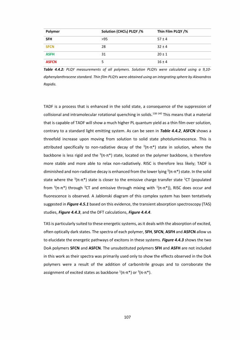
107
Polymer Solution (CHCl3) PLQY /% Thin Film PLQY /%
SFH >95 57 ± 4
SFCN 28 32 ± 4
ASFH 31 20 ± 1
ASFCN 5 16 ± 4
Table 4.4.2: PLQY measurements of all polymers. Solution PLQYs were calculated using a 9,10-
diphenylanthracene standard. Thin film PLQYs were obtained using an integrating sphere by Alexandros
Rapidis.
TADF is a process that is enhanced in the solid state, a consequence of the suppression of
collisional and intramolecular rotational quenching in solids.138-140 This means that a material
that is capable of TADF will show a much higher PL quantum yield as a thin film over solution,
contrary to a standard light emitting system. As can be seen in Table 4.4.2, ASFCN shows a
threefold increase upon moving from solution to solid state photoluminescence. This is
attributed specifically to non-radiative decay of the 3(π-π*) state in solution, where the
backbone is less rigid and the 3(π-π*) state, located on the polymer backbone, is therefore
more stable and more able to relax non-radiatively. RISC is therefore less likely; TADF is
diminished and non-radiative decay is enhanced from the lower lying 3(π-π*) state. In the solid
state where the 3(π-π*) state is closer to the emissive charge transfer state 1CT (populated
from 3(π-π*) through 3CT and emissive through mixing with 1(π-π*)), RISC does occur and
fluorescence is observed. A Jablonski diagram of this complex system has been tentatively
suggested in Figure 4.5.1 based on this evidence, the transient absorption spectroscopy (TAS)
studies, Figure 4.4.3, and the DFT calculations, Figure 4.4.4.
TAS is particularly suited to these energetic systems, as it deals with the absorption of excited,
often optically dark states. The spectra of each polymer, SFH, SFCN, ASFH and ASFCN allow us
to elucidate the energetic pathways of excitons in these systems. Figure 4.4.3 shows the two
DoA polymers SFCN and ASFCN. The unsubstituted polymers SFH and ASFH are not included
in this work as their spectra was primarily used only to show the effects observed in the DoA
polymers were a result of the addition of carbonitrile groups and to corroborate the
assignment of excited states as backbone 1(π-π*) or 3(π-π*).
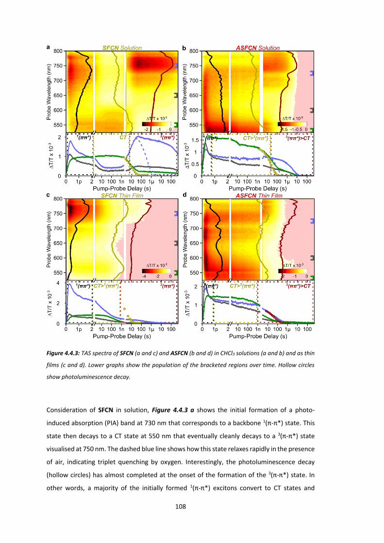
108
Figure 4.4.3: TAS spectra of SFCN (a and c) and ASFCN (b and d) in CHCl3 solutions (a and b) and as thin
films (c and d). Lower graphs show the population of the bracketed regions over time. Hollow circles
show photoluminescence decay.
Consideration of SFCN in solution, Figure 4.4.3 a shows the initial formation of a photo-
induced absorption (PIA) band at 730 nm that corresponds to a backbone 1(π-π*) state. This
state then decays to a CT state at 550 nm that eventually cleanly decays to a 3(π-π*) state
visualised at 750 nm. The dashed blue line shows how this state relaxes rapidly in the presence
of air, indicating triplet quenching by oxygen. Interestingly, the photoluminescence decay
(hollow circles) has almost completed at the onset of the formation of the 3(π-π*) state. In
other words, a majority of the initially formed 1(π-π*) excitons convert to CT states and
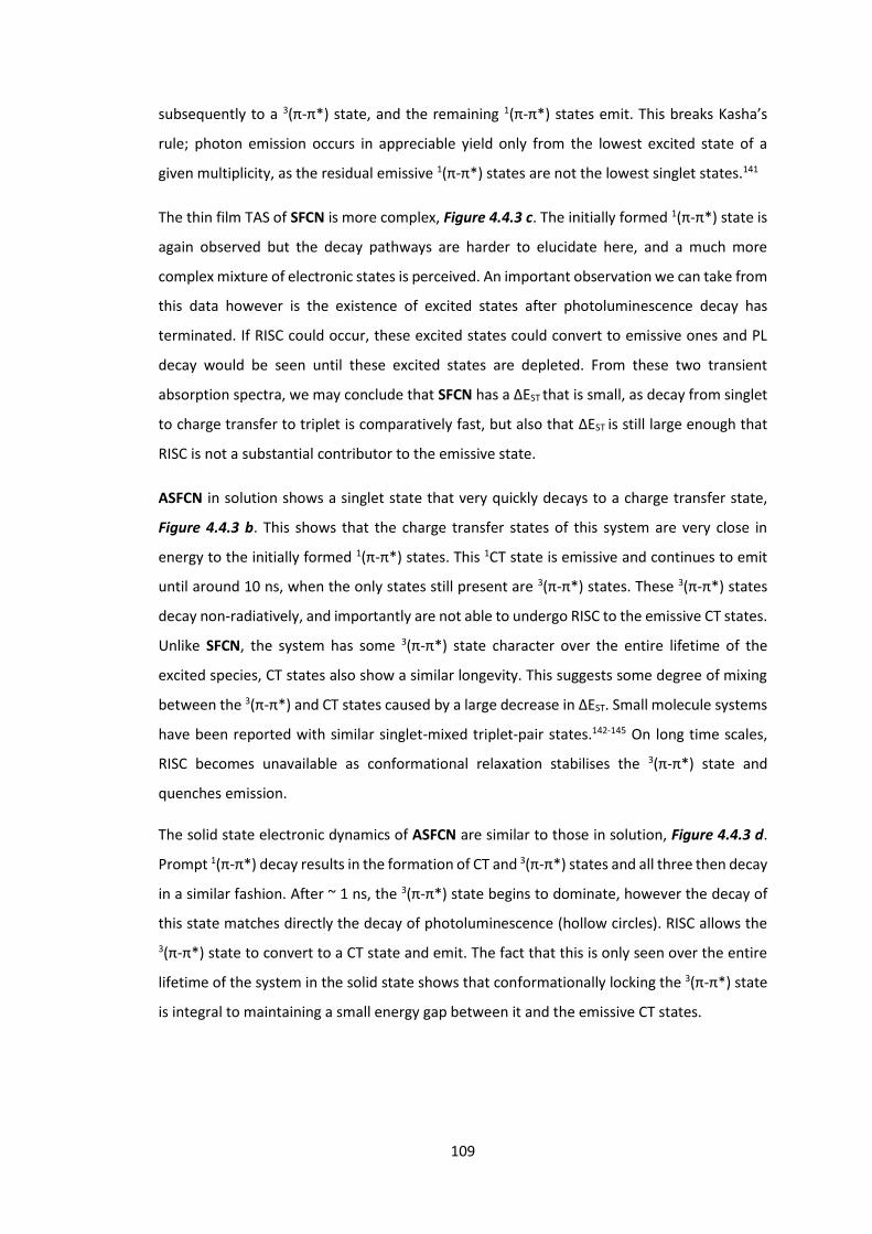
109
subsequently to a 3(π-π*) state, and the remaining 1(π-π*) states emit. This breaks Kasha’s
rule; photon emission occurs in appreciable yield only from the lowest excited state of a
given multiplicity, as the residual emissive 1(π-π*) states are not the lowest singlet states.141
The thin film TAS of SFCN is more complex, Figure 4.4.3 c. The initially formed 1(π-π*) state is
again observed but the decay pathways are harder to elucidate here, and a much more
complex mixture of electronic states is perceived. An important observation we can take from
this data however is the existence of excited states after photoluminescence decay has
terminated. If RISC could occur, these excited states could convert to emissive ones and PL
decay would be seen until these excited states are depleted. From these two transient
absorption spectra, we may conclude that SFCN has a ΔEST that is small, as decay from singlet
to charge transfer to triplet is comparatively fast, but also that ΔEST is still large enough that
RISC is not a substantial contributor to the emissive state.
ASFCN in solution shows a singlet state that very quickly decays to a charge transfer state,
Figure 4.4.3 b. This shows that the charge transfer states of this system are very close in
energy to the initially formed 1(π-π*) states. This 1CT state is emissive and continues to emit
until around 10 ns, when the only states still present are 3(π-π*) states. These 3(π-π*) states
decay non-radiatively, and importantly are not able to undergo RISC to the emissive CT states.
Unlike SFCN, the system has some 3(π-π*) state character over the entire lifetime of the
excited species, CT states also show a similar longevity. This suggests some degree of mixing
between the 3(π-π*) and CT states caused by a large decrease in ΔEST. Small molecule systems
have been reported with similar singlet-mixed triplet-pair states.142-145 On long time scales,
RISC becomes unavailable as conformational relaxation stabilises the 3(π-π*) state and
quenches emission.
The solid state electronic dynamics of ASFCN are similar to those in solution, Figure 4.4.3 d.
Prompt 1(π-π*) decay results in the formation of CT and 3(π-π*) states and all three then decay
in a similar fashion. After ~ 1 ns, the 3(π-π*) state begins to dominate, however the decay of
this state matches directly the decay of photoluminescence (hollow circles). RISC allows the 3(π-π*) state to convert to a CT state and emit. The fact that this is only seen over the entire
lifetime of the system in the solid state shows that conformationally locking the 3(π-π*) state
is integral to maintaining a small energy gap between it and the emissive CT states.
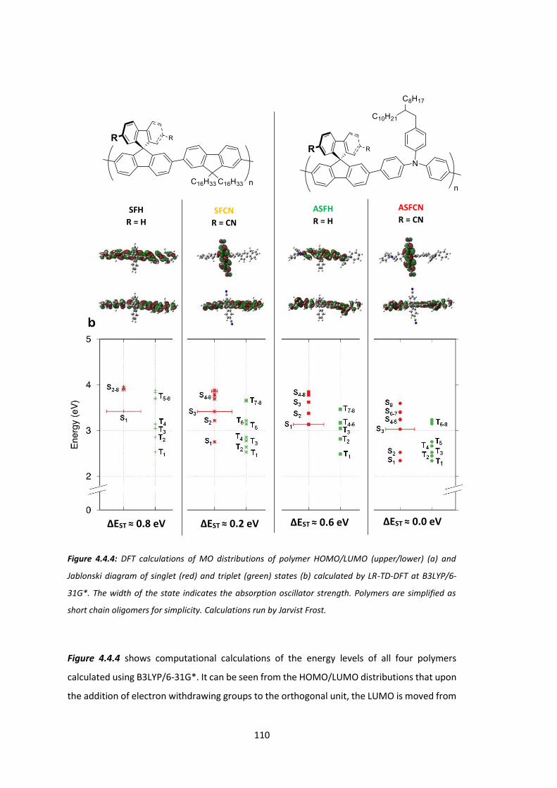
110
Figure 4.4.4: DFT calculations of MO distributions of polymer HOMO/LUMO (upper/lower) (a) and
Jablonski diagram of singlet (red) and triplet (green) states (b) calculated by LR-TD-DFT at B3LYP/6-
31G*. The width of the state indicates the absorption oscillator strength. Polymers are simplified as
short chain oligomers for simplicity. Calculations run by Jarvist Frost.
Figure 4.4.4 shows computational calculations of the energy levels of all four polymers
calculated using B3LYP/6-31G*. It can be seen from the HOMO/LUMO distributions that upon
the addition of electron withdrawing groups to the orthogonal unit, the LUMO is moved from
SFH R = H
ASFH R = H
ASFCN R = CN
ΔEST ≈ 0.8 eV ΔEST ≈ 0.2 eV ΔEST ≈ 0.6 eV ΔEST ≈ 0.0 eV
SFCN R = CN
111
the polymer backbone of SFH and ASFH to the orthogonal unit of SFCN and ASFCN. Thus for
the DoA polymers SFCN and ASFCN, the spatial overlap of the HOMO and LUMO has been
dramatically reduced. Some overlap still remains however, as spiro linkages allow a small
degree of electronic communication between moieties.146
The absorption profile of all polymers remains a π→π* transition from the polymer backbone
to the polymer backbone. This has been previously observed in Figure 4.4.1. Emission in the
form of fluorescence is then observed from the lowest lying singlet state, 1(π-π*), in the case
of the reference polymers SFH and ASFH. The excited 1(π-π*) state in the DoA polymers SFCN
and ASFCN however may undergo internal conversion of a lower energy 1CT state, located on
the orthogonal acceptor. This 1CT state has been stabilised through the addition of
neighbouring electron withdrawing groups and now lies below the 1(π-π*) state of the
polymer backbone. The CT states are a mixture of states containing singlet and triplet
character localised on the orthogonal moiety and spatially separate from the polymer
backbone. The calculated Jablonski diagram clearly shows the DoA polymers have many more
states below the initial 1(π-π*) exciton that may interact.
In SFCN these CT states, mixtures of low lying states on the orthogonal moiety, are around 0.2
eV less stable than the backbone triplet, 3(π-π*). The π* portion (as well as the π) of 3(π-π*) is
calculated to reside on the polymer backbone, and therefore the ΔEST of this system is
calculated to be the difference between the new CT states and the original 3(π-π*) of the
naked polymer. Since 3(π-π*) is spatially separate and more stable than the CT states, RISC
does not occur and SFCN exists as a long lived tripletly excited species.
The lowest lying orthogonal excited states of ASFCN are very close in energy to the 3(π-π*) of
the backbone. ΔEST of this system is therefore very small and the system is capable of RISC
and therfore TADF, as in similar small molecule systems.147
112
4.5 Conclusions
The theoretical predictions of Figure 4.4.4 are in agreement with the conclusions of the
photoluminescence data of Table 4.4.2 and the transient absorption spectroscopy of Figure
4.4.3. It may be unambiguously concluded that the addition of electron withdrawing groups
to an orthogonal moiety in a polymer localises and stabilises the orthogonal π system. This
effectively isolates the excited electron of an exciton from the ground state electron, which
results in a lessening of ΔEST.
A polymer with small (≈ 0.2 eV) ΔEST that has a long lived non-emissive triplet excited state
and a polymer with a negligible (≈ 0.0 eV) ΔEST that undergoes TADF have been synthesised.
By synthesising related polymers with an orthogonal, but not electron withdrawing moiety,
we have proven that the interesting photophysics of these systems is a result of our initial
hypothesis of separating energy levels in space.
By analysing these polymers using TAS, the complex system of excited state energy levels has
been elucidated for each system. Figure 4.5.1 shows a tentative simplified Jablonski diagram
for each polymer, where the orbitals most populated through exciton decay are shown with
the electronic transitions that populate them. In the simplest case, SFH and ASFH, where the
frontier orbitals are localised to the polymer backbone, absorption into an excited singlet state
decays radiatively via fluorescence. The orthogonal groups themselves have no effect on the
band structure of these polymers (the same transitions are observed for PFO and TFB) as the
π* orbitals of the orthogonal groups are much higher up within the conduction band of the
polymer. Triplet states are not formed in these systems.
Stabilisation of the orthogonal π* orbitals via addition of electron withdrawing carbonitrile
groups moves the orthogonal molecular orbitals down to an energy lower than that which is
absorbed into on the backbone. This allows an exciton in the 1(π-π*) orbital (backbone) to
decay to a 1CT state (orthogonal), formed as a result of the new lower energy states on the
orthogonal moiety. The near equivalency in terms of energy of a 3CT state allows electron spin
flip. In the case of SFCN, the 3CT state is close enough in energy, and has enough overlap
through the spiro linkage, to populate the 3(π-π*) of the polymer backbone. The 3(π-π*) state
is 0.2 eV lower in energy and not capable of RISC however, and as it is non-radiative, acts as
an exciton ‘trap’. SFCN therefore has a very long exciton lifetime, but a very low
photoluminescence lifetime. Photoluminescence in this system is observed only from residual

113
1(π-π*) states formed from photon absorption and 1CT states that have not decayed non-
radiatively to the 3(π-π*) state through the 3CT. Emission from these two states is what causes
the broad emission profile of SFCN.
Figure 4.5.1: Proposed simplified Jablonski diagrams of exciton decay for SFH/ASFH (top), SFCN (middle)
and ASFCN (bottom). ‘bb‘ refers to an electron on the polymer backbone, ‘orth’ refers to an electron on
an orthogonal moiety.
ASFCN
SFCN
SFH / ASFH
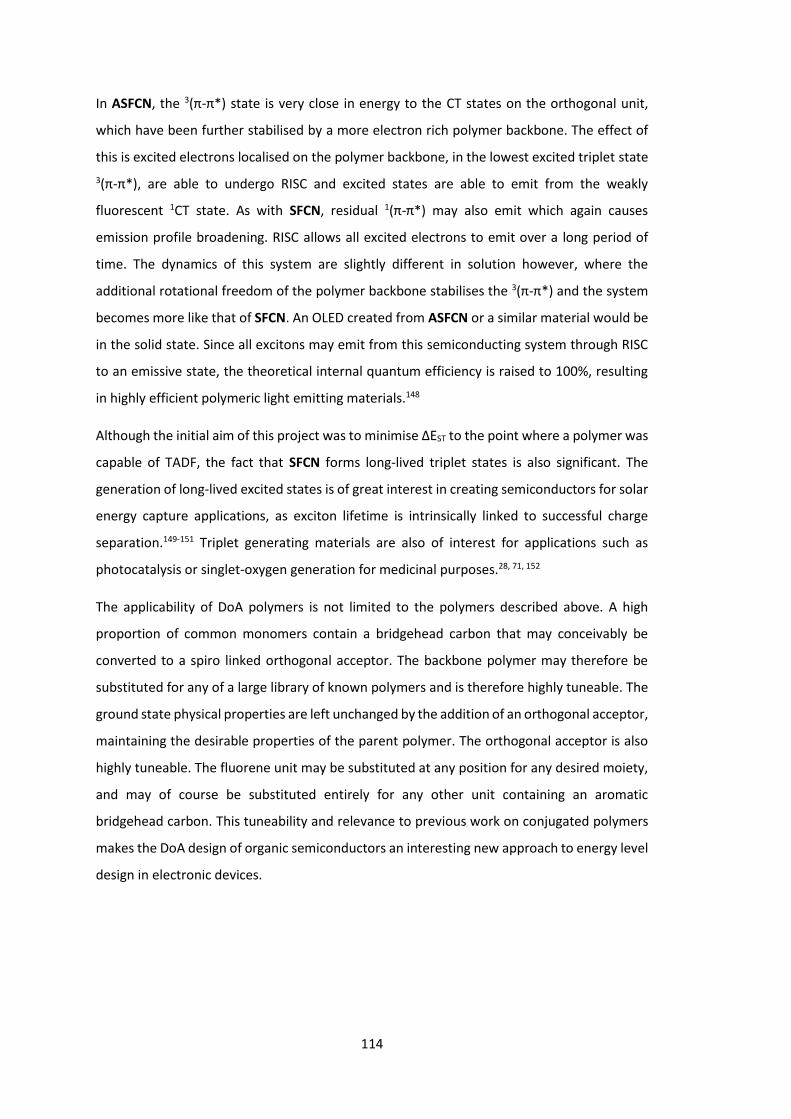
114
In ASFCN, the 3(π-π*) state is very close in energy to the CT states on the orthogonal unit,
which have been further stabilised by a more electron rich polymer backbone. The effect of
this is excited electrons localised on the polymer backbone, in the lowest excited triplet state 3(π-π*), are able to undergo RISC and excited states are able to emit from the weakly
fluorescent 1CT state. As with SFCN, residual 1(π-π*) may also emit which again causes
emission profile broadening. RISC allows all excited electrons to emit over a long period of
time. The dynamics of this system are slightly different in solution however, where the
additional rotational freedom of the polymer backbone stabilises the 3(π-π*) and the system
becomes more like that of SFCN. An OLED created from ASFCN or a similar material would be
in the solid state. Since all excitons may emit from this semiconducting system through RISC
to an emissive state, the theoretical internal quantum efficiency is raised to 100%, resulting
in highly efficient polymeric light emitting materials.148
Although the initial aim of this project was to minimise ΔEST to the point where a polymer was
capable of TADF, the fact that SFCN forms long-lived triplet states is also significant. The
generation of long-lived excited states is of great interest in creating semiconductors for solar
energy capture applications, as exciton lifetime is intrinsically linked to successful charge
separation.149-151 Triplet generating materials are also of interest for applications such as
photocatalysis or singlet-oxygen generation for medicinal purposes.28, 71, 152
The applicability of DoA polymers is not limited to the polymers described above. A high
proportion of common monomers contain a bridgehead carbon that may conceivably be
converted to a spiro linked orthogonal acceptor. The backbone polymer may therefore be
substituted for any of a large library of known polymers and is therefore highly tuneable. The
ground state physical properties are left unchanged by the addition of an orthogonal acceptor,
maintaining the desirable properties of the parent polymer. The orthogonal acceptor is also
highly tuneable. The fluorene unit may be substituted at any position for any desired moiety,
and may of course be substituted entirely for any other unit containing an aromatic
bridgehead carbon. This tuneability and relevance to previous work on conjugated polymers
makes the DoA design of organic semiconductors an interesting new approach to energy level
design in electronic devices.

115

116
Chapter 5: Circularly Polarised Light
Emitting Polymers: Synthesis of Chiral
Monomers
5.1 Introduction
Circularly polarised light (CPL) refers to an electromagnetic wave that has an electrical field
component that has a constant magnitude but rotates around a perpendicular axis relative to
the direction of the wave over time. It differs to linear polarised light which has an electrical
field that changes in magnitude from n to –n on a plane parallel to the direction of the wave,
Figure 5.1.1.
Figure 5.1.1: Linearly polarised light in yz plane (blue) and xz plane (orange) (left) and right handed
circularly polarised light (right). Arrows refer to magnitude and direction of electric field as the wave
travels along the z axis.
Chiral molecules may be utilised to emit CPL in LEDs, or to detect CPL as OFETs.153-154 Early
work used chiral lanthanide complexes,155 however more recently purely organic systems
have been developed for applications in high efficiency display devices,156-158 optical quantum
information processing,159-160 and optical spintronics.161

117
Helicenes have been shown to be attractive molecules for these types of applications.154, 162-
163 As a series of ortho-fused aromatic rings, helicenes have induced chirality as conjoined rings
may not occupy the same space. This creates a helical structure that may exist in both right
and left handed forms that are fully conjugated. Figure 5.1.2 shows some examples of
helicenes used for CPL based applications.
Figure 5.1.2: Helicene structure used in CPL application devices. Shown to cause emission of CPL when
doped into F8BT,163 and may be used as a single small molecule in the detection of CPL in a transistor.154
Polymers have been also been utilised, although there are fewer examples. Polyfluorene may
be synthesised with chiral side chains.164 This results in emission from the non-chiral polymer
chain moderated by the side chains to result in an increase in the polarisation of the emission.
By emitting from a charge transfer state that is itself chiral (electrons are separated across a
stereocentre), it is believed that a great increase in the effective polarisation of emission may
be observed. The basic motif and synthetic route described in the previous chapter may be
used for this application. The spiro centre may be converted to a stereocentre if the rings A
and B, and C and D are different, Figure 5.1.3.
Figure 5.1.3: Retrosynthesis of chiral spiro monomer.
Throughout this chapter, the colour scheme used for the ABCD rings in Figure 5.1.3 will be
used to distinguish which ring system is being synthesised. Different substitution patterns and
ring sizes were trialled for each ring, however the basic spiro structure for the end product
Stereocentre present if:
A ≠ B and C ≠ D

118
was always the same. Ideally, the synthesis of the spiro monomer would be enantiospecific.
A modest ee would be acceptable in this case however, as light emission would still be
polarised. The extent of polarisation would clearly be reduced, but would be adequate in a
proof of concept material.

119
5.2 Synthesis of AB Ring System
Work began with the synthesis of an asymmetric biaryl system with an ortho bromide, the AB
ring system from Figure 5.1.3.
Scheme 5.2.1: Suzuki coupling to form asymmetrical biphenyl 5.2.3 and subsequent unsuccessful
bromination.
Asymmetric biphenyl 5.2.3 was synthesised via Suzuki cross-coupling of bromotoluene 5.2.1
and trifluorotolueneboronic acid 5.2.2. In the final product, the benzylic group would be
converted to a nitrile group in an analogous fashion to the previous chapter. Biphenyl 5.2.3
was then subjected to analogous bromination conditions to those used in the previous
chapter for ortho-bromination of 4,4’-dimethylbiphenyl. An initial attempt using 1.2
equivalents of bromine was unsuccessful and returned starting material. The reaction was
repeated with 5 equivalents of bromine but again, no reaction was observed. This lack of
reactivity is attributed to the electronegativity of the electron withdrawing trifluoromethyl
group resulting in a less electron rich ring system that is less nucleophilic towards bromine.
Scheme 5.2.2: Sandmeyer reaction to form ortho-bromoiodotoluene 5.2.6 and Suzuki reaction giving
undesired disubstituted product 5.2.8.
5.2.1
5.2.2 5.2.3 5.2.4
5.2.5 5.2.6
5.2.7 5.2.8
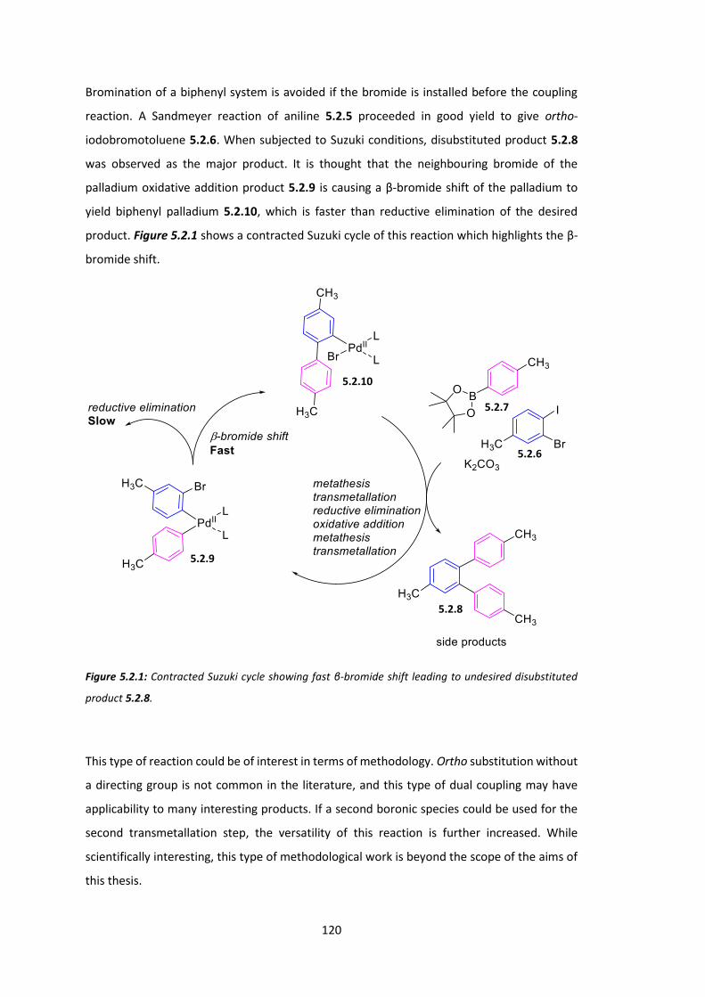
120
Bromination of a biphenyl system is avoided if the bromide is installed before the coupling
reaction. A Sandmeyer reaction of aniline 5.2.5 proceeded in good yield to give ortho-
iodobromotoluene 5.2.6. When subjected to Suzuki conditions, disubstituted product 5.2.8
was observed as the major product. It is thought that the neighbouring bromide of the
palladium oxidative addition product 5.2.9 is causing a β-bromide shift of the palladium to
yield biphenyl palladium 5.2.10, which is faster than reductive elimination of the desired
product. Figure 5.2.1 shows a contracted Suzuki cycle of this reaction which highlights the β-
bromide shift.
Figure 5.2.1: Contracted Suzuki cycle showing fast β-bromide shift leading to undesired disubstituted
product 5.2.8.
This type of reaction could be of interest in terms of methodology. Ortho substitution without
a directing group is not common in the literature, and this type of dual coupling may have
applicability to many interesting products. If a second boronic species could be used for the
second transmetallation step, the versatility of this reaction is further increased. While
scientifically interesting, this type of methodological work is beyond the scope of the aims of
this thesis.
5.2.6
5.2.7
5.2.8
5.2.9
5.2.10

121
The first attempted solution to the undesired bromide shift was to use a protecting group
strategy. Trimethylsilyl (TMS) was initially trialled, Scheme 5.2.3.
Scheme 5.2.3: TMS protecting strategy to AB ring system.
Lithiation ortho to the bromide moiety of trifluorotoluene 5.2.11 was followed with silylation
using TMSCl to yield trifluorotoluene 5.2.12. This was coupled to toluene 5.2.14 under Suzuki
conditions to give biphenyl 5.2.15. Reaction with molecular bromine produced a complex
mixture that was problematic to purify, possibly the result of overbromination. With greater
purification effort, or perhaps more mild conditions, this route may be viable. However at this
point it was judged more expedient to change the target molecule to one that does not initially
contain an electron withdrawing group.
Scheme 5.2.4: Synthesis of meta methyl biphenyl 5.2.19 and (tentatively assigned) para-bromobiphenyl
5.2.19.
5.2.11 5.2.12
5.2.13
5.2.14
5.2.15
5.2.16
5.2.14
5.2.17
5.2.18 5.2.19

122
Suzuki cross coupling was again utilised to synthesise asymmetric biphenyl 5.2.18.
Bromination gave a single product in good yield. The structure of this product has been
tentatively proposed to be para-bromobiphenyl 5.2.19. Bromination (via electrophilic
bromine) will occur either ortho to the phenyl group (2 position), or ortho to the methyl group
(4 position) on ring system A. This occurs as the ortho/para directing phenyl and methyl
groups on the A ring both direct electrophilic attack to these positions. Sterically, it may seem
that the 4 position is more favourable, however this effect seems to be overridden by
electronic effects as can be seen from the bromination of 4,4’-dimethylbiphenyl in the
previous chapter in which bromide is added ortho to the phenyl group (not ortho to methyl).
The stronger electronic effect of the phenyl group could direct the bromide to the 2 or the 4
position in this case however. To elucidate which position had been substituted, an NMR study
was run. It was thought NOSEY NMR may show interactions between the protons of each ring
system that are ortho to the other. These interactions would be different in the 2 or 4
substituted product. 13C, DEPT 135, HMBC and HSQC NMR were also run to unambiguously
assign each proton and carbon in the structure. These studies were inconclusive however as
complications arose surrounding the similar chemical shifts of multiple aromatic protons. The
desired isomer has been previously reported, however the aromatic protons are described
only as a 7H multiplet.165
A cruder method of assignment was then trialled. The cyclisation reaction to form a spiro
bifluorene was attempted, but no product was observed. If this reaction had worked, the
biphenyl must have been the desired 2-substituted isomer. However as it failed the absolute
structure of biphenyl 5.2.19 is still unclear. The product has tentatively been assigned as the
undesired 4-substituted isomer, as it failed to react to form a spirobifluorene.
One possible method of unambiguously assigning the regiochemistry of this molecule could
be to use the halide-induced isotopic shift effect.166-167 With an extremely high resolution 13C
NMR, the different shifts of 35Cl/37Cl (difference of ≈ 5 ppb) or 79Br/81Br (≈ 1 ppb) may be
observed on a directly attached carbon atom. This is a powerful technique, but requires long
scan times and large sample concentrations. If an alternative route to an AB ring system had
not been found, more analytical effort would have been made in the assignment of this
molecule.
Assignment would also be possible with comparative NMR. Scheme 5.2.5 shows a method
designed to unambiguously synthesise the 2-bromobiphenyl isomer.
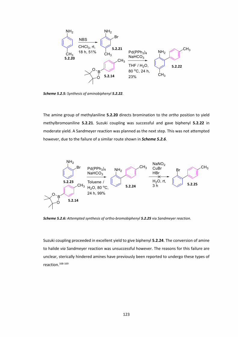
123
Scheme 5.2.5: Synthesis of aminobiphenyl 5.2.22.
The amine group of methylaniline 5.2.20 directs bromination to the ortho position to yield
methylbromoaniline 5.2.21. Suzuki coupling was successful and gave biphenyl 5.2.22 in
moderate yield. A Sandmeyer reaction was planned as the next step. This was not attempted
however, due to the failure of a similar route shown in Scheme 5.2.6.
Scheme 5.2.6: Attempted synthesis of ortho-bromobiphenyl 5.2.25 via Sandmeyer reaction.
Suzuki coupling proceeded in excellent yield to give biphenyl 5.2.24. The conversion of amine
to halide via Sandmeyer reaction was unsuccessful however. The reasons for this failure are
unclear, sterically hindered amines have previously been reported to undergo these types of
reaction.168-169
5.2.20
5.2.21
5.2.14
5.2.22
5.2.14
5.2.23
5.2.24 5.2.25
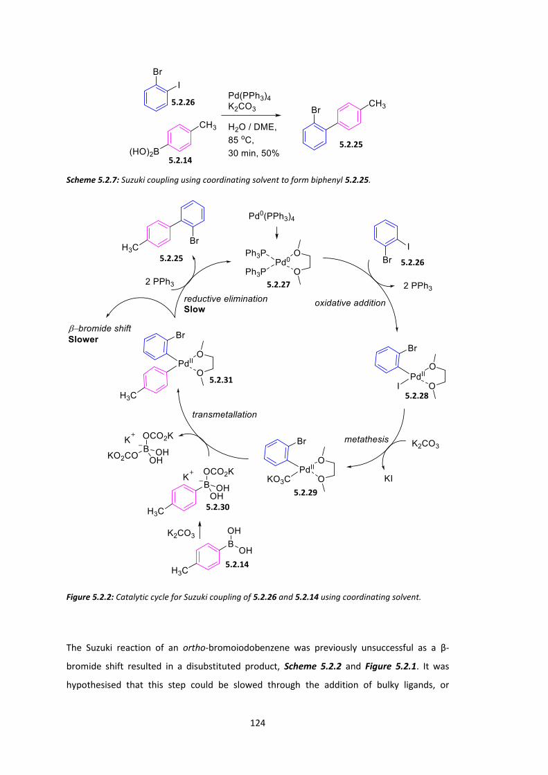
124
Scheme 5.2.7: Suzuki coupling using coordinating solvent to form biphenyl 5.2.25.
Figure 5.2.2: Catalytic cycle for Suzuki coupling of 5.2.26 and 5.2.14 using coordinating solvent.
The Suzuki reaction of an ortho-bromoiodobenzene was previously unsuccessful as a β-
bromide shift resulted in a disubstituted product, Scheme 5.2.2 and Figure 5.2.1. It was
hypothesised that this step could be slowed through the addition of bulky ligands, or
5.2.14
5.2.25
5.2.26
5.2.14
5.2.26
5.2.28
5.2.27
5.2.25
5.2.31
5.2.29
5.2.30
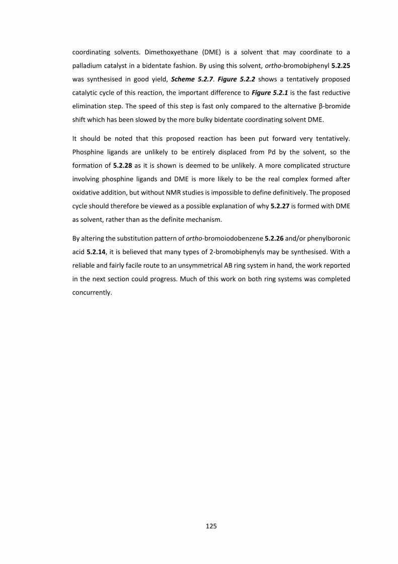
125
coordinating solvents. Dimethoxyethane (DME) is a solvent that may coordinate to a
palladium catalyst in a bidentate fashion. By using this solvent, ortho-bromobiphenyl 5.2.25
was synthesised in good yield, Scheme 5.2.7. Figure 5.2.2 shows a tentatively proposed
catalytic cycle of this reaction, the important difference to Figure 5.2.1 is the fast reductive
elimination step. The speed of this step is fast only compared to the alternative β-bromide
shift which has been slowed by the more bulky bidentate coordinating solvent DME.
It should be noted that this proposed reaction has been put forward very tentatively.
Phosphine ligands are unlikely to be entirely displaced from Pd by the solvent, so the
formation of 5.2.28 as it is shown is deemed to be unlikely. A more complicated structure
involving phosphine ligands and DME is more likely to be the real complex formed after
oxidative addition, but without NMR studies is impossible to define definitively. The proposed
cycle should therefore be viewed as a possible explanation of why 5.2.27 is formed with DME
as solvent, rather than as the definite mechanism.
By altering the substitution pattern of ortho-bromoiodobenzene 5.2.26 and/or phenylboronic
acid 5.2.14, it is believed that many types of 2-bromobiphenyls may be synthesised. With a
reliable and fairly facile route to an unsymmetrical AB ring system in hand, the work reported
in the next section could progress. Much of this work on both ring systems was completed
concurrently.

126
5.3 Synthesis of CD Ring System and Chiral Spiro Monomer
Scheme 5.3.1: Synthetic route to bromoindenothiophenone 5.3.9.
The CD ring system requires an unsymmetrical flourenone-like structure. Scheme 5.3.1 shows
the route towards bromoindenothiophenone 5.3.9, a molecule with a cyclic ketone, differing
ring systems and (after bromination of the thiophene moiety) two aryl halides. When reacted
with a suitable AB ring system, a chiral spiro monomer may be produced.
Bromination of iodobenzoate 5.3.1 occurs para to the iodide moiety and meta to the ester.
No ortho (to iodide) bromination was observed, presumably due to steric effects. The methyl
ester was converted to a carboxylic acid under the reaction conditions to yield
bromoiodobenzylic acid 5.3.2. The methyl ester was reformed in quantitative yield and
bromoiodobenzoate 5.3.3 was subjected to Suzuki conditions with boronic thiophene 5.3.6.
The methyl ester is then again converted to the benzylic acid. Friedel-Crafts conditions allow
the 3-position of the thiophene moiety to attack into the acid chloride, ring closing the
molecule and forming bromoindenothiophene 5.3.9.
5.3.1 5.3.2 5.3.3
5.3.4 5.3.5 5.3.6
5.3.7 5.3.8 5.3.9

127
An interesting observation from this route is the colour of the final product.
Bromoindenothiophene 5.3.9 (one phenyl and one thiophene group) is isolated as a bright
orange powder. The related fluorenone (two phenyl groups) and cyclopentadithiophenone
(two thiophene) exist as bright yellow and deep red solids respectively. It is interesting, but
perhaps unsurprising, that the molecule between these two compounds exists as a solid with
a colour between yellow and red.
Experimentation was performed on the CD ring system 5.3.9 and the AB ring system 5.2.25.
Grignard conditions were first employed, Scheme 5.3.2, analogous to those used in the
previous chapter.
Scheme 5.3.2: Failed Grignard reaction to form chiral spiro molecule 5.3.11.
The Grignard reaction between CD ring system 5.3.9 and the Grignard reagent of AB ring
system 5.2.25, Grignard biphenyl 5.3.10 was successful, but only sporadically and was often
low yielding. Even with careful purification and drying of starting materials, this reaction
continued to be problematic. Rather than focus on solving this issue however, the reaction
type was changed. Lithium halogen exchanged is achieved with nBuLi, a reaction that proved
to be much more facile then Grignard reagent formation, Scheme 5.3.3. HCl in AcOH again
promoted ring closure to form the spiro centre.
5.3.9
5.3.10
5.3.11
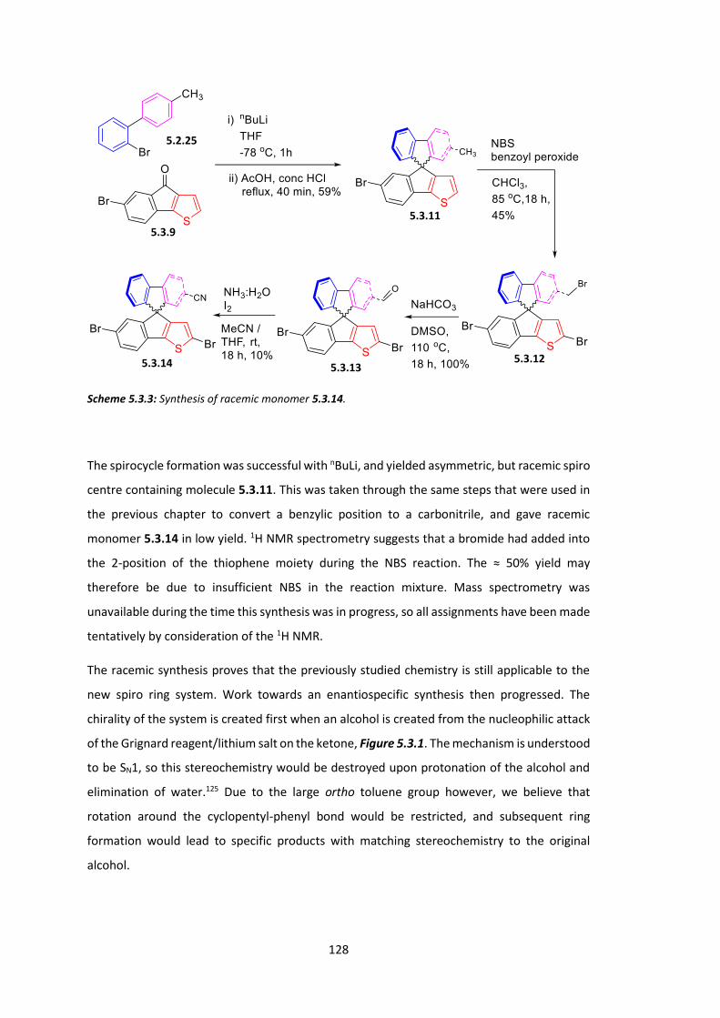
128
Scheme 5.3.3: Synthesis of racemic monomer 5.3.14.
The spirocycle formation was successful with nBuLi, and yielded asymmetric, but racemic spiro
centre containing molecule 5.3.11. This was taken through the same steps that were used in
the previous chapter to convert a benzylic position to a carbonitrile, and gave racemic
monomer 5.3.14 in low yield. 1H NMR spectrometry suggests that a bromide had added into
the 2-position of the thiophene moiety during the NBS reaction. The ≈ 50% yield may
therefore be due to insufficient NBS in the reaction mixture. Mass spectrometry was
unavailable during the time this synthesis was in progress, so all assignments have been made
tentatively by consideration of the 1H NMR.
The racemic synthesis proves that the previously studied chemistry is still applicable to the
new spiro ring system. Work towards an enantiospecific synthesis then progressed. The
chirality of the system is created first when an alcohol is created from the nucleophilic attack
of the Grignard reagent/lithium salt on the ketone, Figure 5.3.1. The mechanism is understood
to be SN1, so this stereochemistry would be destroyed upon protonation of the alcohol and
elimination of water.125 Due to the large ortho toluene group however, we believe that
rotation around the cyclopentyl-phenyl bond would be restricted, and subsequent ring
formation would lead to specific products with matching stereochemistry to the original
alcohol.
5.2.25
5.3.9
5.3.11
5.3.12 5.3.13
5.3.14

129
Figure 5.3.1: Spiro formation steps leading to chiral molecules (S)-5.3.11 and (R)-5.3.11.
As can be seen in Figure 5.3.1, while carbocation 5.3.17 is not chiral, it is likely to exist in two
distinct forms depending on the chirality of alcohol 5.3.16 upon treatment with concentrated
acid. This means that separation of the isomers is possible at the alcohol stage, and would still
(likely) lead to enantiospecific products. Initial methods of enantiospecific synthesis have
therefore focussed around isomer separation at the alcohol stage, rather than inclusion of an
enantioselective reaction.
5.3.9
5.3.15
(S)-5.3.16 (R)- 5.3.16
5.3.17 5.3.17
(R)- 5.3.11 (S)- 5.3.11

130
The first attempted isomer separation involved isolation of the alcohol and recrystallization in
the presence of brucine, a well-known chiral cocrystallising agent shown in Figure 5.3.2.
Brucine is a large and chiral molecule that is used to specifically promote the crystallisation of
a single enantiomer of a molecule in solution. Racemic alcohol 5.3.16 was prepared by
isolating it from the spiro-centre forming reaction before the addition of concentrated acid,
Scheme 5.3.4.
Scheme 5.3.4: Synthesis of racemic alcohol 5.3.16.
Attempts at recrystallization were unsuccessful. Multiple solvents were trailled; acetone,
chloroform and methanol and ethanol. All failed to give significant amounts of crystallised
product, and when an appropriate antisolvent was added slowly, only brucine was observed
to precipitate. This implies that brucine was not encouraging precipitation of a single
enantiomer. Focus was shifted instead to a chiral derivatising agent based strategy.
Figure 5.3.2: Structures of brucine 5.3.18 and Mosher’s acid (R)-5.3.19.
By reacting a racemic molecule (R and S) with an enantiopure derivatising agent (eg. only R),
two diasteriomers are produced as the two steriocentres of the molecule may be in one of
two configurations (R,R and S,R). Since diasteriomers are chemically non-equivalent, standard
purification techniques such as column chromatography become viable to separate the two
5.3.9 5.3.16
5.2.25
5.3.18 (R)-5.3.19
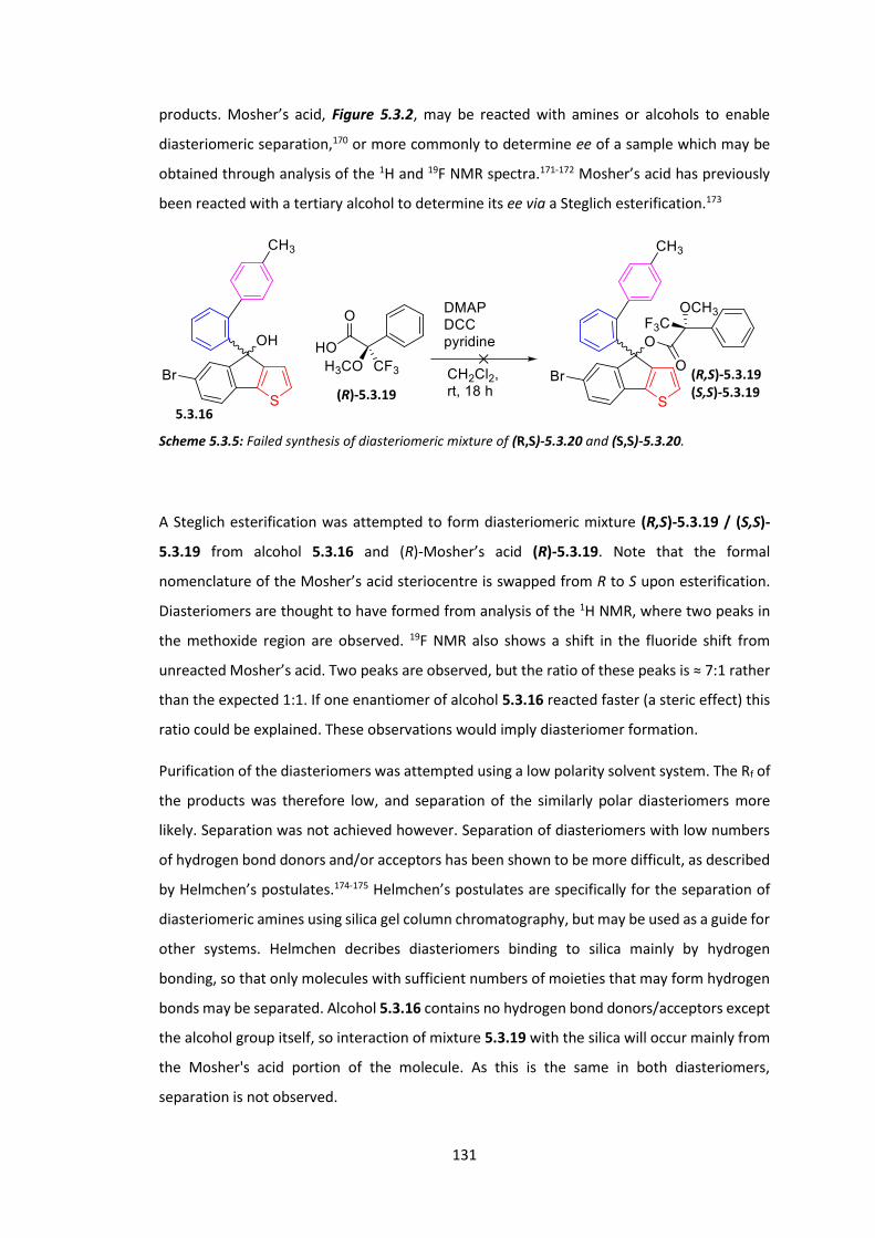
131
products. Mosher’s acid, Figure 5.3.2, may be reacted with amines or alcohols to enable
diasteriomeric separation,170 or more commonly to determine ee of a sample which may be
obtained through analysis of the 1H and 19F NMR spectra.171-172 Mosher’s acid has previously
been reacted with a tertiary alcohol to determine its ee via a Steglich esterification.173
Scheme 5.3.5: Failed synthesis of diasteriomeric mixture of (R,S)-5.3.20 and (S,S)-5.3.20.
A Steglich esterification was attempted to form diasteriomeric mixture (R,S)-5.3.19 / (S,S)-
5.3.19 from alcohol 5.3.16 and (R)-Mosher’s acid (R)-5.3.19. Note that the formal
nomenclature of the Mosher’s acid steriocentre is swapped from R to S upon esterification.
Diasteriomers are thought to have formed from analysis of the 1H NMR, where two peaks in
the methoxide region are observed. 19F NMR also shows a shift in the fluoride shift from
unreacted Mosher’s acid. Two peaks are observed, but the ratio of these peaks is ≈ 7:1 rather
than the expected 1:1. If one enantiomer of alcohol 5.3.16 reacted faster (a steric effect) this
ratio could be explained. These observations would imply diasteriomer formation.
Purification of the diasteriomers was attempted using a low polarity solvent system. The Rf of
the products was therefore low, and separation of the similarly polar diasteriomers more
likely. Separation was not achieved however. Separation of diasteriomers with low numbers
of hydrogen bond donors and/or acceptors has been shown to be more difficult, as described
by Helmchen’s postulates.174-175 Helmchen’s postulates are specifically for the separation of
diasteriomeric amines using silica gel column chromatography, but may be used as a guide for
other systems. Helmchen decribes diasteriomers binding to silica mainly by hydrogen
bonding, so that only molecules with sufficient numbers of moieties that may form hydrogen
bonds may be separated. Alcohol 5.3.16 contains no hydrogen bond donors/acceptors except
the alcohol group itself, so interaction of mixture 5.3.19 with the silica will occur mainly from
the Mosher's acid portion of the molecule. As this is the same in both diasteriomers,
separation is not observed.
(R)-5.3.19
5.3.16
(R,S)-5.3.19 (S,S)-5.3.19

132
Due to the low availability of alcohol 5.3.19, work on the enantiospecific synthesis of a chiral
light emitting monomer was paused at this point. An applicable next step for this project has
been included in the conclusion.

133
5.4 Conclusions
An asymmetric racemic spiro linked monomer has been synthesised. The route towards the
monomer was discovered by splitting the molecule into 4 ring systems. Ring system A was
designed as an aromatic group with ortho bromide and ring system B was designed to have
various functionality. Initially, both A and B had benzylic groups that would be converted to
electron withdrawing nitrile groups in the final monomer. Various iterations were trialled, but
the final system had a single methyl group on the B ring and represents a simple molecule that
could be synthesised fairly quickly and allowed further experimentation further down the
route. It is thought that different functionality could be introduced by using the same
chemistry on alternative starting materials (for example methyl group on the A ring, or in
different positions for both).
The CD ring system was designed as a phenyl group for C and a thiophene for D. A five step
convergent synthesis yields this system in sufficient amounts to enable experimentation on
the spiro cycle formation reaction and subsequent steps. Again, it is thought that different
substitution patterns around these ring systems would be possible. The variability is not as
high as for the AB ring system however, as bromides must be installed to enable
polymerisation.
The Grignard conditions used for spiro cycle formation in the previous chapter were not
successful in a first attempt on these reactants. nBuLi was substituted, and found to be a more
reproducible choice for this reaction. Using similar chemistry to the previous chapter, the
methyl group of ring system B was converted to a nitrile group. This created a monomer with
a spiro steriocentre.
This monomer was synthesised in a racemic fashion however. First attempts at modifying the
route to be enantioselective revolved around the tertiary alcohol created as an intermediate
in the spiro cycle formation reaction. Chiral resolution was first attempted through a
recrystallization with brucine, however separation of enantiomers failed. Mosher’s acid was
then employed to create two diasteriomers that would be separated by column
chromatography. It is thought that the esterification was successful, however separation on
standard silica column was not observed. We attribute this to a lack of hydrogen bond
character, as stated in Helmchen's postulates.
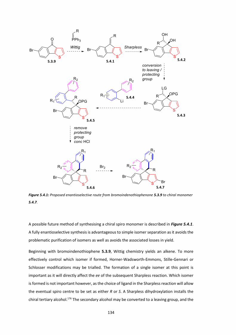
134
Figure 5.4.1: Proposed enantioselective route from bromoindenothiophenone 5.3.9 to chiral monomer
5.4.7.
A possible future method of synthesising a chiral spiro monomer is described in Figure 5.4.1.
A fully enantioselective synthesis is advantageous to simple isomer separation as it avoids the
problematic purification of isomers as well as avoids the associated losses in yield.
Beginning with bromoindenothiophene 5.3.9, Wittig chemistry yields an alkene. To more
effectively control which isomer if formed, Horner-Wadsworth-Emmons, Stille-Gennari or
Schlosser modifications may be trialled. The formation of a single isomer at this point is
important as it will directly affect the ee of the subsequent Sharpless reaction. Which isomer
is formed is not important however, as the choice of ligand in the Sharpless reaction will allow
the eventual spiro centre to be set as either R or S. A Sharpless dihydroxylation installs the
chiral tertiary alcohol.176 The secondary alcohol may be converted to a leaving group, and the
5.3.9 5.4.1 5.4.2
5.4.3
5.4.4
5.4.5
5.4.6 5.4.7

135
tertiary may then be protected, indenothiophene 5.4.3. Reaction of the AB system with nBuLi
forms the lithium salt 5.4.4 which will preferentially react with the leaving group and yield
indenothiophene 5.4.5. Deprotection of the tertiary alcohol allows the second stage of spiro
cycle formation, the same chemistry as previously with the exception of the creation of a six
rather than five membered ring. Bromination of the thiophene 2 position yields the monomer
5.4.7.
A problem with this route has already been discussed. Figure 5.3.1 shows how
stereochemistry is maintained even though chirality is destroyed during the SN1 mechanism
of this reaction. It should be noted that this attributed mechanism is based on only a single
paper, but that the paper in question has a very similar system.125 With a one-carbon extended
structure, rotation may be much more facile. This could racemise the system at this stage.
Care must therefore be taken at this stage to ensure ee is not overly compromised. As the
molecule would exist as diasteriomers (since the stereochemistry of the carbon attached to R
has already been set and would not change during the route), 1H NMR should be sufficient to
observe if any racemisation at this stage has taken place.

136
Chapter 6: Experimental
6.1 General Procedures
General procedure 1: The Formation of A2B2-Porphyrins from Relevant Dipyrromethane and
Aldehyde
A solution of relevant dipyrromethane (1.0 eq), aldehyde (1.0 eq) and CH2Cl2 was degassed
and either TFA or BF3.Et2O (various equivalents used) was added slowly in the dark under an
argon atmosphere. The reaction mixture was stirred for 30 min. DDQ (1.2 eq) was added and
the reaction mixture was stirred for a further 4 h.
General procedure 2: Platinum Complexation of Porphyrins with PtCl2
A solution of PtCl2 (2 eq) in benzonitrile was heated to 100 oC. The porphyrin (1.0 eq) was
added in one portion and the reaction mixture was heated to reflux and stirred for 18 h. The
reaction mixture was then cooled and concentrated in vacuo.
137
Reagents and Solvents: All reagents and solvents were used as received. MeOH, CH2Cl2 and
n-hexane were HiPerSolv grade. Et2O and EtOAc were GPR grade. Pet 40-60 refers to BDH
AnalaR petroleum spirit 40-60 oC. All other chemicals were used as supplied unless otherwise
indicated.
Experimental techniques: All reactions were carried out in oven-dried glassware under an
argon atmosphere unless otherwise indicated. Air and moisture sensitive reagents were
transferred by syringe. Reactions performed at temperatures other than rt were recorded as
silicon oil bath temperatures. The phrase “concentrated in vacuo” refers to rotary
evaporation. Brine refers to an aqueous solution of NaCl. Column chromatography was carried
out using BDH (40-60 µm) silica gel and analytical thin layer chromatography was carried out
using Merck Keiselgel aluminium-backed plates coated with silica gel. If necessary,
components were visualised using combinations of ultra-violet light and potassium
permanganate.
Characterisation: 1H NMR spectra were recorded at 300 MHz on a Bruker AMX300
spectrometer, at 500 MHz on a Bruker Avance 500 spectrometer, or at 600 MHz on a Bruker
Avance 600 spectrometer in the stated solvent using residual protic solvent CHCl3 (δ = 7.26
ppm, s), DMSO (δ = 2.56 ppm, qn) or pyridine (δ = 8.74 ppm, s; 7.58 ppm, s; 7.22 ppm, s) as
the internal standard. Chemical shifts are quoted in ppm using the following abbreviations: s,
singlet; d, doublet; t, triplet; q, quartet; qn, quintet; m, multiplet; br, broad or a combination
of these. The coupling constants (J) are measured in Hertz. 13C NMR spectra were recorded at
75 MHz on a Bruker AMX300 spectrometer, at 125 MHz on a Bruker Avance 500 spectrometer
or at 150 MHz on a Bruker Avance 600 spectrometer in the stated solvent using the central
reference of CHCl3 (δ = 77.0 ppm, t), DMSO (δ = 39.52 ppm, septet) as the internal standard.
Chemical shifts are reported to the nearest 0.1 ppm. UV-visible spectra were recorded, at
room temperature, on a Thermo Unicam UV500 spectrometer, in CH2Cl2 solutions at
concentrations of ~10-5 M. Thin films of polymers were spin coated from CH2Cl2 solutions of
10 mg/mL on a Laurell spin coater at 2000 rpm for 30 s. Mass spectra was obtained from the
mass spectrometry service at the Department of Chemistry, University College London.
Number-average (Mn) and weight-average (Mw) molecular weights were determined against
a polystyrene standard using an Agilent Technologies 1200 series GPC in chlorobenzene at 80
°C.

138
PF MPP(Pt) optical properties, device fabrication and testing (work carried out by Dr. Guilia
Tregnago):
The optical properties of the copolymers have been investigated in the solid state. We
deposited a 100 nm thick film for each compolymer via spin coating (1.8 krpm) a 2 wt.%
toluene solution over a Spectrosil fused silica substrate. The steady-state photoluminescence
(PL) spectra were recorded after exciting the PL with a 405 nm diode laser with an ANDOR
Shamrock spectrograph coupled with an ANDOR Newton CCD unit. Time-resolved PL
measurements were carried out with a time-correlated single photon counting (TCSPC)
spectrometer using a pulsed diode laser (Edinburgh Instruments-EPL-405) at 405 nm as
excitation source and a cooled photomultiplier (Becker & Hickl PMC-100-1) coupled to a
monochromator and TCSPC electronics (Edinburgh Instrument Lifespec-ps TCC-900 PC card).
The PL efficiency was measured using an integrating sphere method.177 The copolymers were
also tested in PLED devices as the active layer. OLEDs were fabricated by spin-coating (4 krpm)
a 2.8 wt.% dispersion in water of poly(3,4-ethylenedioxythiophene)-poly(styrenesulfonate)178
(PEDOT:PSS, Sigma Aldrich) to a thickness of a 80 nm over an ITO-coated glass pre-treated
with oxygen plasma179(10 min at 10.2 W). The substrates were then baked at 150 °C for 10
min in a nitrogen atmosphere to remove residual water. The active layer was deposited by
spin-coating (2 krpm) a 2 wt.% toluene solution to obtain a thickness of 100 nm. Ca/Al
electrodes (30 nm/150 nm respectively) were thermally evaporated under vacuum 10-6 mbar)
on top of the active layer. Current-voltage-radiance characteristics were measured with a
Keithley 2004 source meter and a calibrated Si photodiode (wavelength range of 200-1100
nm) coupled with a Keithley 2000 multimeter, electroluminescence (EL) spectra were taken
with the ANDOR spectrometer described above.
PDPA MPP(Pt) optical properties, device fabrication and testing (work carried out by Dr.
Alessandro Minotto):
Thin films and devices were prepared and analysed as for the PF MPP(Pt) polymers above.
OLEDs were fabricated by using ITO/PEDOT:PSS anodes, active layer (90 nm) and Ca (30
nm)/Al (150 nm) cathodes.
ASFCN and related polymers optical properties, device fabrication and testing (work carried
out by Dr. Andrew Musser):
Spectroscopic sample preparation: For solution measurements, polymers were dissolved in
chloroform in nitrogen atmosphere to a concentration of 625 µg/mL. The solution was
139
transferred to a 1 mm path-length quartz cuvette (Hellma Analytics) and tightly sealed prior
to removal from the glove box. For oxygen-exposure measurements, the cuvette was opened
and the solution was bubbled with air for ~1 minute. Thin films were spun on cleaned quartz
substrates from room-temperature chloroform solutions (5 mg/mL) at low speed (1500 rpm)
in a nitrogen-filled glove box. They were stored under nitrogen and measured in vacuum or
He exchange gas atmosphere. Where oxygen exposure was unavoidable, the films were kept
under vacuum or purged with He vapour for >30 minutes prior to measurement.
Photoluminescence spectroscopy: PL measurements were acquired on three systems, one
equipped with a N2 bath cryostat and the others with a continuous-flow He cryostat.
Steadystate photoluminescence spectra were collected on a Fluoromax fluorimeter (Horiba)
with excitation at 370 nm, from above room temperature to near liquid-nitrogen
temperatures each equipped with a continuous-flow He cryostat. Spectra were also collected
down to liquid He temperatures using a pulsed laser at 407 nm (PicoQuant LDH400) run at 2.5
MHz and a 500 mm focal length spectrograph (Princeton Instruments, SpectraPro2500i) with
a cooled CCD camera. Single-wavelength dynamics were acquired using the same excitation
source and a time-correlated single photon counting system using a monochromator coupled
to photomultiplier detectors (Hamamatsu R3809U-50). Simultaneously time- and
spectrallyresolved photoluminescence decay was measured with a gated, intensified CCD
camera (Andor, iStar) mounted on a 300 mm focal length spectrograph (Andor, Shamrock SR-
303i). S4 Solid State Photoluminescence Quantum Yields Spectrosil substrates (UQG) were
cleaned in acetone and IPA in ultrasonic bath (10min each step) and dried with N2. In a
nitrogen glovebox, 5 mg/ml solutions in anhydrous chloroform were spin-coated at 1500 rpm.
Excitation : λ = 405 nm (ThorLabs laser diode). Sample handling in a dark environment with
yellow light (spin coating) and a small stylus torch (sample positioning during measurements).
Measurements in a nitrogen glovebox. Spectra collected with ANDOR-Shamrock 163
spectrometer coupled with an ANDOR-Newton CCD unit. Solution Photoluminescence
Quantum Yields Solution Quantum Yields were measured in dilute chloroform solutions (Amax
~ 0.02-0.05 in order to avoid inner filter effects and ensure linear response on the intensity.
Samples were bubbled with Argon for 30 minutes prior to measurement. Quantum Yields are
reported relative to Diphenylanthracene in cyclohexane (0.95). Spectra were recorded on a
Horiba Fluoromax-4. All spectra are corrected. Transient absorption spectroscopy: Sub-
picosecond transient absorption (TA) measurements were performed on a previously
reported setup with slight modifications. 2 Narrow-band (~10 nm) excitation pulses at 400 nm
were generated in an optical parametric amplifier (TOPAS, Light Conversion Ltd.) coupled to
140
the output of a 1 kHz regenerative amplifier (Spectra-Physics Solstice). The sample
transmission was probed using broadband Top View of the setup S5 pulses generated in two
home-built non-collinear optical parametric amplifiers (NOPAs) roughly spanning 500-1125
nm. The probe beam was split to provide a reference signal not affected by the pump to
mitigate any laser fluctuation effects, and both were dispersed in a spectrometer (Andor,
Shamrock SR-303i) and detected using a pair of linear image sensors (Hamamatsu, G11608)
driven and read out at the full laser repetition rate by a custom-built board from Stresing
Entwicklungsbüro. The differential transmission (ΔT/T) was then measured as a function of
probe wavelength and pump-probe delay, with the pump-probe delay set by a mechanical
delay stage (maximum extension ~1700 ps). This setup afforded a temporal resolution of
approximately 120 fs. The same setup was employed for subnanosecond TA, using the third-
harmonic (355 nm) nanosecond output of a Q-switched Nd:YVO4 laser as the excitation
source. The pulse duration and electronic jitter resulted in an instrument response of ~1.5 ns.
Data is presented with a break at 1.5-3 ns, which marks the switch from sub-ps to sub-ns
excitation setups and a change in excitation wavelength from 400 nm to 355 nm. Where both
are presented together, sub-ns-excitation data was scaled to account for differences in
excitation density between the two measurements.
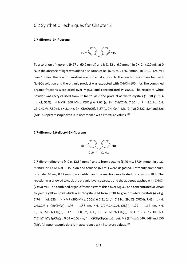
141
6.2 Synthetic Techniques for Chapter 2
2,7-dibromo-9H-fluorene
To a solution of fluorene (9.97 g, 60.0 mmol) and I2 (1.52 g, 6.0 mmol) in CH2Cl2 (120 mL) at 0 oC in the absence of light was added a solution of Br2 (6.50 mL, 126.0 mmol) in CH2Cl2 (24 mL)
over 10 min. The reaction mixture was stirred at rt for 6 h. The reaction was quenched with
Na2SO3 solution and the organic product was extracted with CH2Cl2 (100 mL). The combined
organic fractions were dried over MgSO4 and concentrated in vacuo. The resultant white
powder was recrystallised from EtOAc to yield the product as white crystals (10.18 g, 31.4
mmol, 52%). 1H NMR (500 MHz, CDCl3) δ 7.67 (s, 2H, CH2CCH), 7.60 (d, J = 8.1 Hz, 2H,
CBrCHCH), 7.50 (d, J = 8.1 Hz, 2H, CBrCHCH), 3.87 (s, 2H, CH2); MS (CI+) m/z 322, 324 and 326
(M)+. All spectroscopic data is in accordance with literature values.180
2,7-dibromo-9,9-dioctyl-9H-fluorene
2,7-dibromofluorene (4.0 g, 12.34 mmol) and 1-bromooctane (6.40 mL, 37.04 mmol) in a 1:1
mixture of 13 M NaOH solution and toluene (60 mL) were degassed. Tetrabutylammonium
bromide (40 mg, 0.12 mmol) was added and the reaction was heated to reflux for 18 h. The
reaction was allowed to cool, the organic layer separated and the aqueous washed with CH2Cl2
(2 x 50 mL). The combined organic fractions were dried over MgSO4 and concentrated in vacuo
to yield a yellow solid which was recrystallized from EtOH to give off white crystals (4.24 g,
7.74 mmol, 63%). 1H NMR (500 MHz, CDCl3) δ 7.51 (d, J = 7.9 Hz, 2H, CBrCHCH), 7.45 (m, 4H,
CH2CCH + CBrCHCH), 1.95 – 1.86 (m, 4H, C(CH2CH2C5H10CH3)2), 1.27 – 1.17 (m, 4H,
C(CH2CH2C5H10CH3)2), 1.17 – 1.00 (m, 16H, C(CH2CH2C5H10CH3)2), 0.83 (t, J = 7.2 Hz, 6H,
C(CH2CH2C5H10CH3)2), 0.64 – 0.53 (m, 4H, C(CH2CH2C5H10CH3)2); MS (EI+) m/z 546, 548 and 550
(M)+. All spectroscopic data is in accordance with literature values.181
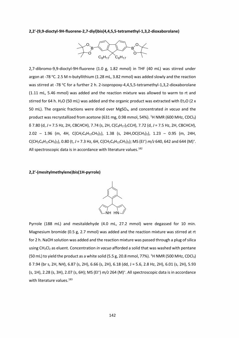
142
2,2'-(9,9-dioctyl-9H-fluorene-2,7-diyl)bis(4,4,5,5-tetramethyl-1,3,2-dioxaborolane)
2,7-dibromo-9,9-dioctyl-9H-fluorene (1.0 g, 1.82 mmol) in THF (40 mL) was stirred under
argon at -78 oC. 2.5 M n-butyllithium (1.28 mL, 3.82 mmol) was added slowly and the reaction
was stirred at -78 oC for a further 2 h. 2-isopropoxy-4,4,5,5-tetramethyl-1,3,2-dioxaborolane
(1.11 mL, 5.46 mmol) was added and the reaction mixture was allowed to warm to rt and
stirred for 64 h. H2O (50 mL) was added and the organic product was extracted with Et2O (2 x
50 mL). The organic fractions were dried over MgSO4, and concentrated in vacuo and the
product was recrystallized from acetone (631 mg, 0.98 mmol, 54%). 1H NMR (600 MHz, CDCl3)
δ 7.80 (d, J = 7.5 Hz, 2H, CBCHCH), 7.74 (s, 2H, C(C8H17)2CCH), 7.72 (d, J = 7.5 Hz, 2H, CBCHCH),
2.02 – 1.96 (m, 4H, C(CH2C6H12CH3)2), 1.38 (s, 24H,OC(CH3)2), 1.23 – 0.95 (m, 24H,
C(CH2C6H12CH3)2), 0.80 (t, J = 7.3 Hz, 6H, C(CH2C6H12CH3)2); MS (EI+) m/z 640, 642 and 644 (M)+.
All spectroscopic data is in accordance with literature values.182
2,2'-(mesitylmethylene)bis(1H-pyrrole)
Pyrrole (188 mL) and mesitaldehyde (4.0 mL, 27.2 mmol) were degassed for 10 min.
Magnesium bromide (0.5 g, 2.7 mmol) was added and the reaction mixture was stirred at rt
for 2 h. NaOH solution was added and the reaction mixture was passed through a plug of silica
using CH2Cl2 as eluent. Concentration in vacuo afforded a solid that was washed with pentane
(50 mL) to yield the product as a white solid (5.5 g, 20.8 mmol, 77%). 1H NMR (500 MHz, CDCl3)
δ 7.94 (br s, 2H, NH), 6.87 (s, 2H), 6.66 (s, 2H), 6.18 (dd, J = 5.6, 2.8 Hz, 2H), 6.01 (s, 2H), 5.93
(s, 1H), 2.28 (s, 3H), 2.07 (s, 6H); MS (EI+) m/z 264 (M)+. All spectroscopic data is in accordance
with literature values.183

143
5,15-bis(4-bromophenyl)-10,20-dimesitylporphyrin (MPP)
Product was prepared according to general procedure 1 from 2,2'-(mesitylmethylene)bis(1H-
pyrrole) (0.54 g, 2.04 mmol) and 4-bromobenzaldehyde (0.38 g, 2.04 mmol) in CH2Cl2 (250 mL)
using TFA (0.28 mL, 3.68 mmol) and DDQ (0.56 g, 2.45 mmol). The reaction mixture was
purified by silica plug using CH2Cl2 as eluent. Concentration in vacuo and washing with MeOH
(100 mL) yielded the product as purple crystals (156 mg, 0.19 mmol, 18%). 1H NMR (500 MHz,
CDCl3) δ 8.77 (d, J = 4.7 Hz, 4H, NHCCH), 8.70 (d, J = 4.7 Hz, 4H, NHCCH), 8.09 (d, J = 8.2 Hz, 4H,
CBrCHCH), 7.88 (d, J = 8.2 Hz, 4H, CBrCHCH), 7.29 (s, 4H, NHCCCC(CH3)CHCCH3), 2.63 (s, 6H,
NHCCCC(CH3)CHCCH3), 1.83 (s, 12H, NHCCCC(CH3)CHCCH3), -2.66 (s, 2H, NH); 13C NMR (151
MHz, CDCl3) δ 141.0, 139.5, 138.3, 138.0, 135.9, 132.6, 131.1, 130.0, 127.9, 122.5, 118.8,
118.0, 114.4, 21.8, 21.6; MS (EI+) m/z 855, 857 and 859 (M[+H])+; HRMS 855.1698 calculated
for C50H4179Br2N4 found 855.1660.
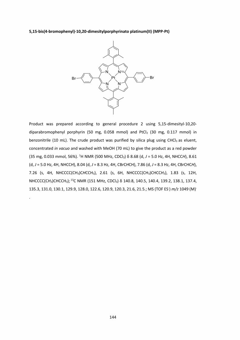
144
5,15-bis(4-bromophenyl)-10,20-dimesitylporphyrinato platinum(II) (MPP-Pt)
Product was prepared according to general procedure 2 using 5,15-dimesityl-10,20-
diparabromophenyl porphyrin (50 mg, 0.058 mmol) and PtCl2 (30 mg, 0.117 mmol) in
benzonitrile (10 mL). The crude product was purified by silica plug using CHCl3 as eluent,
concentrated in vacuo and washed with MeOH (70 mL) to give the product as a red powder
(35 mg, 0.033 mmol, 56%). 1H NMR (500 MHz, CDCl3) δ 8.68 (d, J = 5.0 Hz, 4H, NHCCH), 8.61
(d, J = 5.0 Hz, 4H, NHCCH), 8.04 (d, J = 8.3 Hz, 4H, CBrCHCH), 7.86 (d, J = 8.3 Hz, 4H, CBrCHCH),
7.26 (s, 4H, NHCCCC(CH3)CHCCH3), 2.61 (s, 6H, NHCCCC(CH3)CHCCH3), 1.83 (s, 12H,
NHCCCC(CH3)CHCCH3); 13C NMR (151 MHz, CDCl3) δ 140.8, 140.5, 140.4, 139.2, 138.1, 137.4,
135.3, 131.0, 130.1, 129.9, 128.0, 122.6, 120.9, 120.3, 21.6, 21.5.; MS (TOF ES-) m/z 1049 (M)-
.
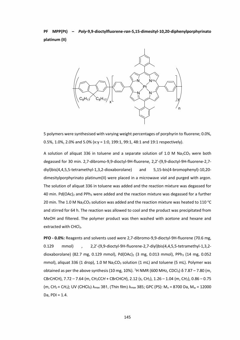
145
PF MPP(Pt) – Poly-9,9-dioctylfluorene-ran-5,15-dimesityl-10,20-diphenylporphyrinato
platinum (II)
5 polymers were synthesised with varying weight percentages of porphyrin to fluorene; 0.0%,
0.5%, 1.0%, 2.0% and 5.0% (x:y = 1:0, 199:1, 99:1, 48:1 and 19:1 respectively).
A solution of aliquat 336 in toluene and a separate solution of 1.0 M Na2CO3 were both
degassed for 30 min. 2,7-dibromo-9,9-dioctyl-9H-fluorene, 2,2'-(9,9-dioctyl-9H-fluorene-2,7-
diyl)bis(4,4,5,5-tetramethyl-1,3,2-dioxaborolane) and 5,15-bis(4-bromophenyl)-10,20-
dimesitylporphyrinato platinum(II) were placed in a microwave vial and purged with argon.
The solution of aliquat 336 in toluene was added and the reaction mixture was degassed for
40 min. Pd(OAc)2 and PPh3 were added and the reaction mixture was degassed for a further
20 min. The 1.0 M Na2CO3 solution was added and the reaction mixture was heated to 110 oC
and stirred for 64 h. The reaction was allowed to cool and the product was precipitated from
MeOH and filtered. The polymer product was then washed with acetone and hexane and
extracted with CHCl3.
PFO - 0.0%: Reagents and solvents used were 2,7-dibromo-9,9-dioctyl-9H-fluorene (70.6 mg,
0.129 mmol) , 2,2'-(9,9-dioctyl-9H-fluorene-2,7-diyl)bis(4,4,5,5-tetramethyl-1,3,2-
dioxaborolane) (82.7 mg, 0.129 mmol), Pd(OAc)2 (3 mg, 0.013 mmol), PPh3 (14 mg, 0.052
mmol), aliquat 336 (1 drop), 1.0 M Na2CO3 solution (1 mL) and toluene (5 mL). Polymer was
obtained as per the above synthesis (10 mg, 10%). 1H NMR (600 MHz, CDCl3) δ 7.87 – 7.80 (m,
CBrCHCH), 7.72 – 7.64 (m, CH2CCH + CBrCHCH), 2.12 (s, CH2), 1.26 – 1.04 (m, CH2), 0.86 – 0.75
(m, CH2 + CH3); UV (CHCl3) λmax 381, (Thin film) λmax 385; GPC (PS): Mn = 8700 Da, Mw = 12000
Da, PDI = 1.4.
146
P1 - 0.5%: Reagents and solvents used were 2,7-dibromo-9,9-dioctyl-9H-fluorene (140.5 mg,
0.256 mmol) , 2,2'-(9,9-dioctyl-9H-fluorene-2,7-diyl)bis(4,4,5,5-tetramethyl-1,3,2-
dioxaborolane) (165.3 mg, 0.257 mmol), 5,15-bis(4-bromophenyl)-10,20-
dimesitylporphyrinato platinum(II) (1.2 mg, 0.001 mmol), Pd(OAc)2 (6 mg, 0.026 mmol), PPh3
(28 mg, 0.104 mmol), aliquat 336 (2 drops), 1.0 M Na2CO3 solution (2 mL) and toluene (10 mL).
Polymer was obtained as per the above synthesis (99 mg, 50%). 1H NMR (600 MHz, CDCl3) δ
9.13 (s, MPPH), 8.93 (s, MPPH), 8.41 (s, MPPH), 8.13 (s, MPPH), 7.87 – 7.81 (m, CBrCHCH), 7.73
– 7.63 (m, CH2CCH + CBrCHCH), 2.23 – 2.01 (m, CH2), 1.25 – 1.03 (m, CH2), 0.90 – 0.72 (m, CH2
+ CH3); UV (CHCl3) λmax 380, (Thin film) λmax 383; GPC (PS): Mn = 8000 Da, Mw = 15000 Da, PDI
= 1.8.
P2 - 1.0%: Reagents and solvents used were 2,7-dibromo-9,9-dioctyl-9H-fluorene (139.9 mg,
0.255 mmol) , 2,2'-(9,9-dioctyl-9H-fluorene-2,7-diyl)bis(4,4,5,5-tetramethyl-1,3,2-
dioxaborolane) (165.3 mg, 0.257 mmol), 5,15-bis(4-bromophenyl)-10,20-
dimesitylporphyrinato platinum(II) (2.4 mg, 0.002 mmol), Pd(OAc)2 (6 mg, 0.026 mmol), PPh3
(28 mg, 0.104 mmol), aliquat 336 (2 drops), 1.0 M Na2CO3 solution (2 mL) and toluene (10 mL).
Polymer was obtained as per the above synthesis (198 mg, 99%). 1H NMR (600 MHz, CDCl3) δ
9.13 (s, MPPH), 8.93 (s, MPPH), 8.41 (s, MPPH), 8.13 (s, MPPH), 7.89 – 7.80 (m, CBrCHCH), 7.74
– 7.62 (m, CH2CCH + CBrCHCH), 2.12 (s, CH2), 1.30 – 0.99 (m, CH2), 0.91 – 0.67 (m, CH2 + CH3);
UV (CHCl3) λmax 381, (Thin film) λmax 383; GPC (PS): Mn = 11000 Da, Mw = 20000 Da, PDI = 1.8.
P3 - 2.0%: Reagents and solvents used were 2,7-dibromo-9,9-dioctyl-9H-fluorene (69.3 mg,
0.124 mmol) , 2,2'-(9,9-dioctyl-9H-fluorene-2,7-diyl)bis(4,4,5,5-tetramethyl-1,3,2-
dioxaborolane) (82.7 mg, 0.129 mmol), 5,15-bis(4-bromophenyl)-10,20-
dimesitylporphyrinato platinum(II) (2.4 mg, 0.002 mmol), Pd(OAc)2 (3 mg, 0.013 mmol), PPh3
(14 mg, 0.052 mmol), aliquat 336 (1 drop), 1.0 M Na2CO3 solution (1 mL) and toluene (5 mL).
Polymer was obtained as per the above synthesis (80 mg, 80%). 1H NMR (600 MHz, CDCl3) δ
9.13 (s, MPPH), 8.64 (s, MPPH), 8.36 (s, MPPH), 8.11 (s, MPPH), 7.88 – 7.80 (m, CBrCHCH), 7.75
– 7.63 (m, CH2CCH + CBrCHCH), 2.12 (s, CH2), 1.17 (s, CH2), 0.90 – 0.73 (m, CH2 + CH3); UV
(CHCl3) λmax 379, (Thin film) λmax 385; GPC (PS): Mn = 11000 Da, Mw = 17000 Da, PDI = 1.6.
P4 - 5.0%: Reagents and solvents used were 2,7-dibromo-9,9-dioctyl-9H-fluorene (67.5 mg,
0.123 mmol) , 2,2'-(9,9-dioctyl-9H-fluorene-2,7-diyl)bis(4,4,5,5-tetramethyl-1,3,2-
dioxaborolane) (82.7 mg, 0.129 mmol), 5,15-bis(4-bromophenyl)-10,20-
dimesitylporphyrinato platinum(II) (5.9 mg, 0.006 mmol), Pd(OAc)2 (3 mg, 0.013 mmol), PPh3
(14 mg, 0.052 mmol), aliquat 336 (1 drop), 1.0 M Na2CO3 solution (1 mL) and toluene (5 mL).
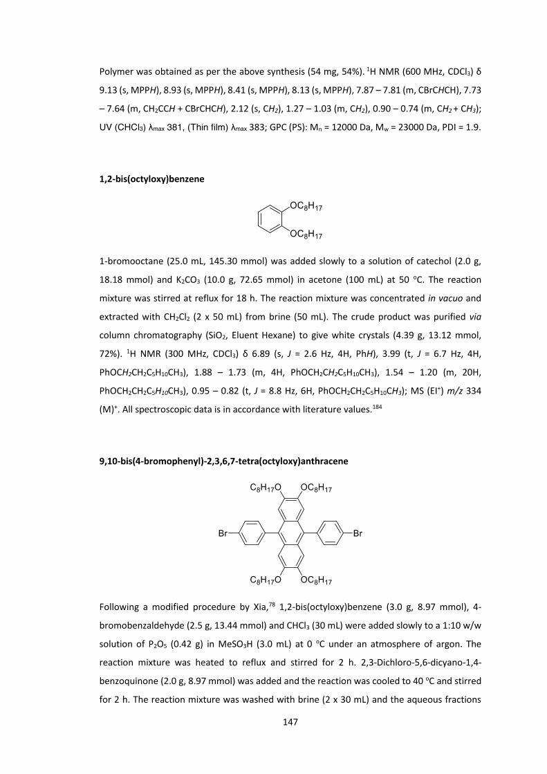
147
Polymer was obtained as per the above synthesis (54 mg, 54%). 1H NMR (600 MHz, CDCl3) δ
9.13 (s, MPPH), 8.93 (s, MPPH), 8.41 (s, MPPH), 8.13 (s, MPPH), 7.87 – 7.81 (m, CBrCHCH), 7.73
– 7.64 (m, CH2CCH + CBrCHCH), 2.12 (s, CH2), 1.27 – 1.03 (m, CH2), 0.90 – 0.74 (m, CH2 + CH3);
UV (CHCl3) λmax 381, (Thin film) λmax 383; GPC (PS): Mn = 12000 Da, Mw = 23000 Da, PDI = 1.9.
1,2-bis(octyloxy)benzene
1-bromooctane (25.0 mL, 145.30 mmol) was added slowly to a solution of catechol (2.0 g,
18.18 mmol) and K2CO3 (10.0 g, 72.65 mmol) in acetone (100 mL) at 50 oC. The reaction
mixture was stirred at reflux for 18 h. The reaction mixture was concentrated in vacuo and
extracted with CH2Cl2 (2 x 50 mL) from brine (50 mL). The crude product was purified via
column chromatography (SiO2, Eluent Hexane) to give white crystals (4.39 g, 13.12 mmol,
72%). 1H NMR (300 MHz, CDCl3) δ 6.89 (s, J = 2.6 Hz, 4H, PhH), 3.99 (t, J = 6.7 Hz, 4H,
PhOCH2CH2C5H10CH3), 1.88 – 1.73 (m, 4H, PhOCH2CH2C5H10CH3), 1.54 – 1.20 (m, 20H,
PhOCH2CH2C5H10CH3), 0.95 – 0.82 (t, J = 8.8 Hz, 6H, PhOCH2CH2C5H10CH3); MS (EI+) m/z 334
(M)+. All spectroscopic data is in accordance with literature values.184
9,10-bis(4-bromophenyl)-2,3,6,7-tetra(octyloxy)anthracene
Following a modified procedure by Xia,78 1,2-bis(octyloxy)benzene (3.0 g, 8.97 mmol), 4-
bromobenzaldehyde (2.5 g, 13.44 mmol) and CHCl3 (30 mL) were added slowly to a 1:10 w/w
solution of P2O5 (0.42 g) in MeSO3H (3.0 mL) at 0 oC under an atmosphere of argon. The
reaction mixture was heated to reflux and stirred for 2 h. 2,3-Dichloro-5,6-dicyano-1,4-
benzoquinone (2.0 g, 8.97 mmol) was added and the reaction was cooled to 40 oC and stirred
for 2 h. The reaction mixture was washed with brine (2 x 30 mL) and the aqueous fractions

148
were further extracted with CHCl3 (2 x 50 mL). The organic fractions were dried over MgSO4
and concentrated in vacuo. The crude product was purified via column chromatography (SiO2,
Eluent Et2O:Hexane (1:19)) and recrystallization from CHCl3 and MeOH (716 mg, 0.72 mmol,
8%). 1H NMR (300 MHz, CDCl3) δ 7.73 (d, J = 8.3 Hz, 4H, PhH), 7.33 (d, J = 8.3 Hz, 4H, PhH), 6.72
(s, 4H, C8H17OCCH), 3.85 (t, J = 6.5 Hz, 8H, OCH2CH2C5H10CH3), 1.83 – 1.69 (m, 8H,
OCH2CH2C5H10CH3), 1.48 – 1.19 (m, 40H, OCH2CH2C5H10CH3), 0.88 (t, J = 6.7 Hz, 12H,
OCH2CH2C5H10CH3); 13C NMR (151 MHz, CDCl3) δ 149.0, 139.0, 133.0, 132.0, 131.5, 125.7,
121.6, 105.1, 68.7, 32.0, 29.5, 29.4, 29.0, 26.2, 22.8, 14.3; MS (ES+) m/z 998, 1000, 1002 (M)+;
HRMS 998.4424 calculated for C58H8079Br2O4 found 998.5254.
PDPA MPP(Pt) – Poly-4’,4’’-(2,3,6,7-(octyloxy)-9,10-diphenylanthracene-alt-1,4-phenyl)-
ran-(4’,4’’-5,15-dimesityl-10,20-diphenylporphyrin(Pt)-alt-1,4-phenyl)
4 polymers were synthesised with varying weight percentages of porphyrin to
diphenylanthracene moiety; 0.0%, 1.0%, 5.0% and 10.0% (x:y = 1:0, 99:1, 19:1 and 9:1).
A mixture of 9,10-bis(4-bromophenyl)-2,3,6,7-tetrakis(octyloxy)anthracene, 1,4-bis(4,4,5,5-
tetramethyl-1,3,2-dioxaborolan-2-yl)benzene, 5,15-bis(4-bromophenyl)-10,20-
dimesitylporphyrinato platinum(II), Pd2(dba)3, (o-tol)3P, aliquat 336, and toluene was
degassed in a microwave vial for 30 min. A degassed 1.0 M solution of Na2CO3 was added and
the reaction mixture was stirred for 3 d at 120 oC. The reaction was allowed to cool and the
product was precipitated from MeOH and filtered. The polymer product was then washed
with acetone and hexane and extracted with CHCl3.

149
PDPA: Reagents and solvents used were 9,10-bis(4-bromophenyl)-2,3,6,7-
tetrakis(octyloxy)anthracene (108.9 mg, 0.109 mmol), 1,4-bis(4,4,5,5-tetramethyl-1,3,2-
dioxaborolan-2-yl)benzene (35.9 mg, 0.109 mmol), Pd2(dba)3 (2.0 mg, 0.002 mmol), (o-tol)3P
(2.6 mg, 0.009 mmol), aliquat 336 (1 drop), 1.0 M Na2CO3 (1.0 mL), and toluene (4.0 mL).
Polymer was obtained as per the above synthesis (79 mg, 79%). UV (chlorobenzene) λmax 381;
GPC (PS): Mn = 7800 Da, Mw = 10000 Da, PDI = 1.3.
PDPA MPP(Pt) 1: Reagents and solvents used were 9,10-bis(4-bromophenyl)-2,3,6,7-
tetrakis(octyloxy)anthracene (216.1 mg, 0.216 mmol), 1,4-bis(4,4,5,5-tetramethyl-1,3,2-
dioxaborolan-2-yl)benzene (71.8 mg, 0.218 mmol), 5,15-bis(4-bromophenyl)-10,20-
dimesitylporphyrinato platinum(II) (2.2 mg, 0.002 mmol), Pd2(dba)3 (4.0 mg, 0.004 mmol), (o-
tol)3P (5.2 mg, 0.017 mmol), aliquat 336 (1 drop), 1.0 M Na2CO3 (2.0 mL), and toluene (8.0 mL).
Polymer was obtained as per the above synthesis (120 mg, 60%). UV (chlorobenzene) λmax
382; GPC (PS): Mn = 8800 Da, Mw = 12000 Da, PDI = 1.4.
PDPA MPP(Pt) 5: Reagents and solvents used were 9,10-bis(4-bromophenyl)-2,3,6,7-
tetrakis(octyloxy)anthracene (103.7 mg, 0.104 mmol), 1,4-bis(4,4,5,5-tetramethyl-1,3,2-
dioxaborolan-2-yl)benzene (35.9 mg, 0.109 mmol), 5,15-bis(4-bromophenyl)-10,20-
dimesitylporphyrinato platinum(II) (5.4 mg, 0.005 mmol), Pd2(dba)3 (2.0 mg, 0.002 mmol), (o-
tol)3P (2.6 mg, 0.009 mmol), aliquat 336 (1 drop), 1.0 M Na2CO3 (1.0 mL), and toluene (4.0 mL).
Polymer was obtained as per the above synthesis (80 mg, 80%). UV (chlorobenzene) λmax 408;
GPC (PS): Mn = 12000 Da, Mw = 20000 Da, PDI = 1.7.
PDPA MPP(Pt) 10: Reagents and solvents used were 9,10-bis(4-bromophenyl)-2,3,6,7-
tetrakis(octyloxy)anthracene (98.2 mg, 0.098 mmol), 1,4-bis(4,4,5,5-tetramethyl-1,3,2-
dioxaborolan-2-yl)benzene (35.9 mg, 0.109 mmol), 5,15-bis(4-bromophenyl)-10,20-
dimesitylporphyrinato platinum(II) (10.9 mg, 0.010 mmol), Pd2(dba)3 (2.0 mg, 0.002 mmol),
(o-tol)3P (2.6 mg, 0.009 mmol), aliquat 336 (1 drop), 1.0 M Na2CO3 (1.0 mL), and toluene (4.0
mL). Polymer was obtained as per the above synthesis (42 mg, 42%). UV (chlorobenzene) λmax
411; GPC (PS): Mn = 11000 Da, Mw = 21000 Da, PDI = 1.8.

150

151
6.3 Synthetic Techniques for Chapter 3
3-(4-bromophenyl)propynol
1-iodo-4-bromobenzene (1.0 g, 3.54 mmol) and copper iodide (42 mg, 0.22 mmol) in toluene
(20 mL) were degassed for 10 min. Propargyl alcohol (0.26 mL, 3.54 mmol) and piperidine
(0.70 mL, 7.03 mmol) were added, resulting in a yellow solution.
Bis(triphenylphosphine)palladium(II) dichloride (70 mg, 0.10 mmol) was added and the
reaction was stirred at 35 oC for 2 h. The reaction mixture was passed through a silica plug
using CHCl3 as eluent and concentrated in vacuo. The crude solid off-white product (744 mg,
3.52 mmol, 99%) was taken into the next reaction without further purification. 1H NMR (500
MHz, CDCl3) δ 7.45 (d, J = 8.4 Hz, 2H, CBrCHCH), 7.29 (d, J = 8.4 Hz, 2H, CBrCHCH), 4.48 (s, 2H,
CCCHOH). All spectroscopic data is in accordance with literature values.185
3-(4-bromophenyl)propiolaldehyde
Crude 3-(4-bromophenyl)propynol (1.60 g, 7.58 mmol), TEMPO (119 mg, 0.76 mmol),
(Diacetoxyiodo)benzene (2.90 g, 9.10 mmol) and CH2Cl2 (100 mL) were stirred under argon at
rt for 3 h. Na2SO3 solution (150 mL) and CH2Cl2 (100 mL) were added and the organic layer was
separated. The aqueous layer was washed with CH2Cl2 (2 x 100mL) and the combined organic
fractions were dried over MgSO4 and concentrated in vacuo. The crude product was purified
via column chromatography (SiO2, Eluent Hexane:Et2O (9:1)) to give the desired product as an
off white solid (862 mg, 4.13 mmol, 54%). 1H NMR (500 MHz, CDCl3) δ 9.41 (s, 1H, CCCHO),
7.56 (d, J = 8.7 Hz, 2H, CBrCHCH), 7.46 (d, J = 8.7 Hz, 2H, CBrCHCH); MS (CI+) m/z 209 and 211
(M[+H])+. All spectroscopic data is in accordance with literature values.186
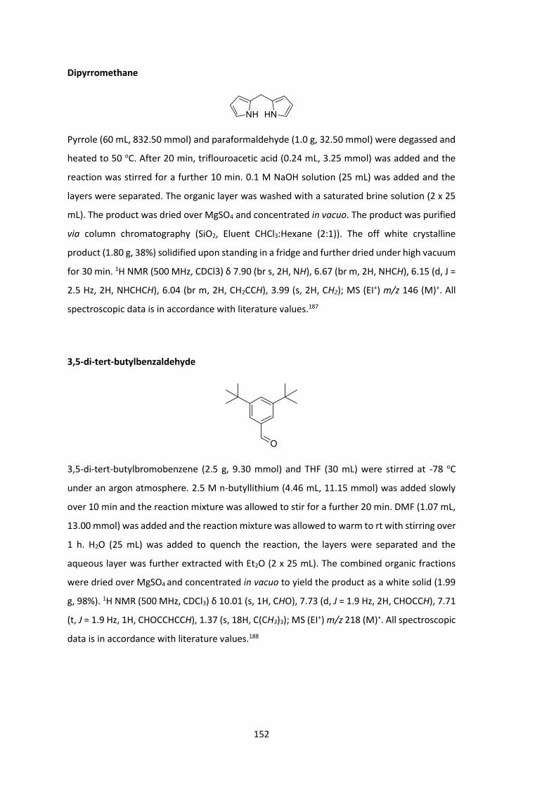
152
Dipyrromethane
Pyrrole (60 mL, 832.50 mmol) and paraformaldehyde (1.0 g, 32.50 mmol) were degassed and
heated to 50 oC. After 20 min, triflouroacetic acid (0.24 mL, 3.25 mmol) was added and the
reaction was stirred for a further 10 min. 0.1 M NaOH solution (25 mL) was added and the
layers were separated. The organic layer was washed with a saturated brine solution (2 x 25
mL). The product was dried over MgSO4 and concentrated in vacuo. The product was purified
via column chromatography (SiO2, Eluent CHCl3:Hexane (2:1)). The off white crystalline
product (1.80 g, 38%) solidified upon standing in a fridge and further dried under high vacuum
for 30 min. 1H NMR (500 MHz, CDCl3) δ 7.90 (br s, 2H, NH), 6.67 (br m, 2H, NHCH), 6.15 (d, J =
2.5 Hz, 2H, NHCHCH), 6.04 (br m, 2H, CH2CCH), 3.99 (s, 2H, CH2); MS (EI+) m/z 146 (M)+. All
spectroscopic data is in accordance with literature values.187
3,5-di-tert-butylbenzaldehyde
3,5-di-tert-butylbromobenzene (2.5 g, 9.30 mmol) and THF (30 mL) were stirred at -78 oC
under an argon atmosphere. 2.5 M n-butyllithium (4.46 mL, 11.15 mmol) was added slowly
over 10 min and the reaction mixture was allowed to stir for a further 20 min. DMF (1.07 mL,
13.00 mmol) was added and the reaction mixture was allowed to warm to rt with stirring over
1 h. H2O (25 mL) was added to quench the reaction, the layers were separated and the
aqueous layer was further extracted with Et2O (2 x 25 mL). The combined organic fractions
were dried over MgSO4 and concentrated in vacuo to yield the product as a white solid (1.99
g, 98%). 1H NMR (500 MHz, CDCl3) δ 10.01 (s, 1H, CHO), 7.73 (d, J = 1.9 Hz, 2H, CHOCCH), 7.71
(t, J = 1.9 Hz, 1H, CHOCCHCCH), 1.37 (s, 18H, C(CH3)3); MS (EI+) m/z 218 (M)+. All spectroscopic
data is in accordance with literature values.188
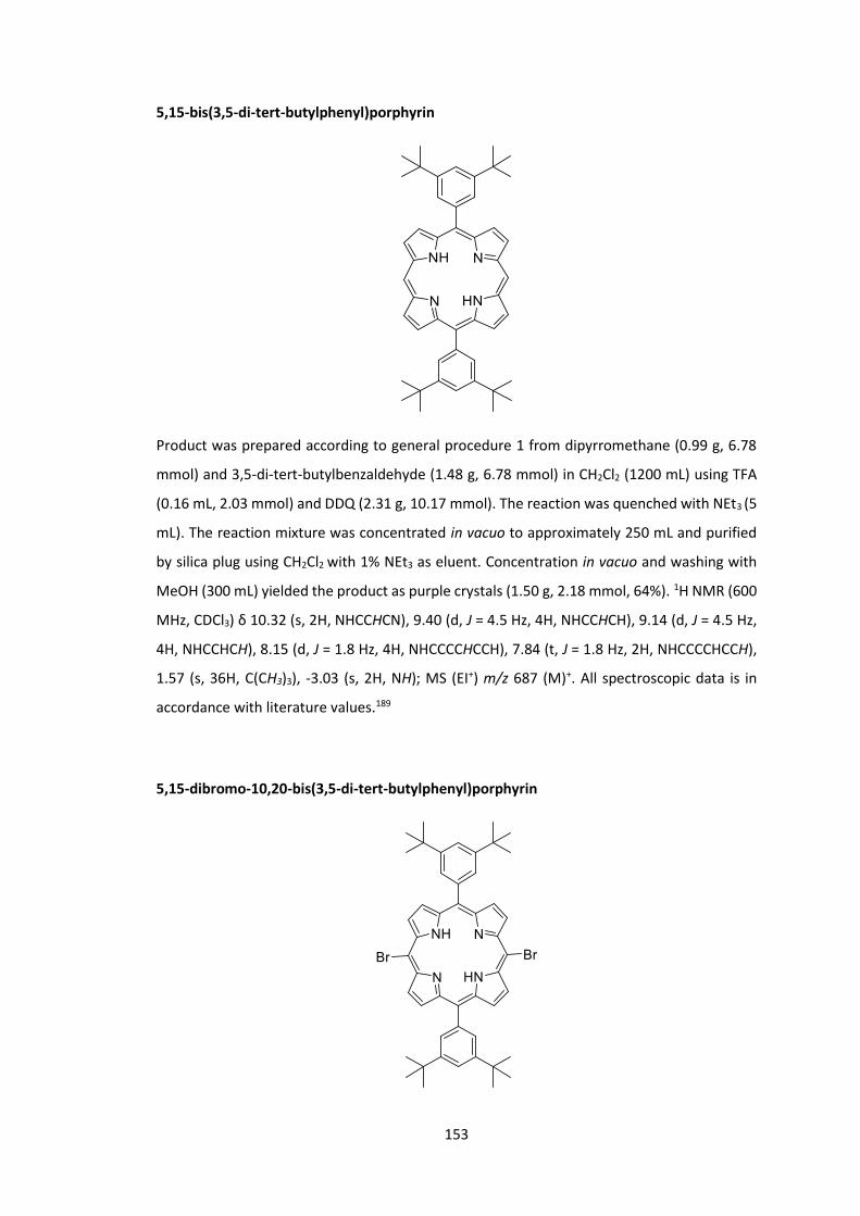
153
5,15-bis(3,5-di-tert-butylphenyl)porphyrin
Product was prepared according to general procedure 1 from dipyrromethane (0.99 g, 6.78
mmol) and 3,5-di-tert-butylbenzaldehyde (1.48 g, 6.78 mmol) in CH2Cl2 (1200 mL) using TFA
(0.16 mL, 2.03 mmol) and DDQ (2.31 g, 10.17 mmol). The reaction was quenched with NEt3 (5
mL). The reaction mixture was concentrated in vacuo to approximately 250 mL and purified
by silica plug using CH2Cl2 with 1% NEt3 as eluent. Concentration in vacuo and washing with
MeOH (300 mL) yielded the product as purple crystals (1.50 g, 2.18 mmol, 64%). 1H NMR (600
MHz, CDCl3) δ 10.32 (s, 2H, NHCCHCN), 9.40 (d, J = 4.5 Hz, 4H, NHCCHCH), 9.14 (d, J = 4.5 Hz,
4H, NHCCHCH), 8.15 (d, J = 1.8 Hz, 4H, NHCCCCHCCH), 7.84 (t, J = 1.8 Hz, 2H, NHCCCCHCCH),
1.57 (s, 36H, C(CH3)3), -3.03 (s, 2H, NH); MS (EI+) m/z 687 (M)+. All spectroscopic data is in
accordance with literature values.189
5,15-dibromo-10,20-bis(3,5-di-tert-butylphenyl)porphyrin

154
To a solution of 5,15-H-10,20-di(bismetatertbutylbenzene) pophyrin (225 mg, 0.33 mmol) in
CHCl3 (20 mL) was added NBS (123 mg, 0.689 mmol) and pyridine (0.3 mL), the reaction
mixture was stirred at rt for 10 min. The reaction was quenched with acetone (10 mL),
concentrated in vacuo and washed with MeOH (100 mL) to yield purple crystals (225 mg, 0.266
mmol, 81%). 1H NMR (500 MHz, CDCl3) δ 9.63 (d, J = 4.4 Hz, 4H, NHCCH), 8.88 (d, J = 4.4 Hz,
4H, NHCCH), 8.02 (s, 4H, NHCCCCHCCH), 7.83 (s, 2H, NHCCCCHCCH), 1.54 (d, J = 3.6 Hz, 36H,
C(CH3)3), -2.67 (s, 2H, NH); m/z 842, 844 and 846 (M)+; HRMS 843.2637 calculated for
C48H5379Br2N4 found 843.2615. All spectroscopic data is in accordance with literature values.190
2-bromo7hexylthiophene
3-hexylthiophene (1.07 mL, 5.94 mmol), NBS (1.06 g, 5.94 mmol) and AcOH (5 mL) were stirred
at rt under an argon atmosphere for 18 h. The reaction mixture was then poured into a
saturated NaHCO3 solution (20 mL) and extracted with Et2O (2 x 30 mL). The combined organic
fractions were washed with saturated NaHCO3 solution (2 x 20mL), dried over MgSO4 and
concentrated in vacuo to afford the product (1.03 g, 4.17 mmol, 70%). 1H NMR (500 MHz,
CDCl3) δ 7.18 (d, J = 5.6 Hz, 1H, SCHCH), 6.79 (d, J = 5.6 Hz, 1H, SCHCH), 2.57 (t, J = 7.6 Hz, 2H,
SCBrC(CH2CH2C3H6CH3)), 1.62 – 1.52 (m, 2H, SCBrC(CH2CH2C3H6CH3)), 1.38 – 1.26 (m, 6H,
SCBrC(CH2CH2C3H6CH3)), 0.89 (t, J = 6.9 Hz, 3H, SCBrC(CH2CH2C3H6CH3)). All spectroscopic data
is in accordance with literature values.191
((3-hexylthiophen6yl)ethynyl)trimethylsilane
An anhydrous solution of 2-bromo7hexylthiophene (1.03 g, 4.17 mmol),
ethynyltrimethylsilane (0.88 mL, 6.26 mmol), Pd(OAc)2 (29 mg, 0.13 mmol), PPh3 (100 mg, 0.38
mmol), CuI (40 mg, 0.21 mmol), NEt3 (10 mL) and CH2Cl2 (10 mL) were degassed in a dry flask
and stirred at 50 oC for 18 h under an argon atmosphere. The reaction mixture was filtered
and concentrated in vacuo and the product was purified via column chromatography (SiO2,
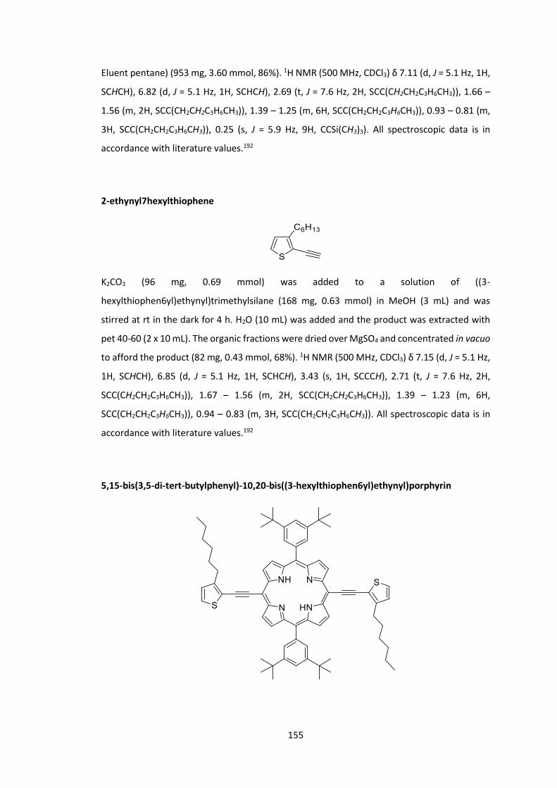
155
Eluent pentane) (953 mg, 3.60 mmol, 86%). 1H NMR (500 MHz, CDCl3) δ 7.11 (d, J = 5.1 Hz, 1H,
SCHCH), 6.82 (d, J = 5.1 Hz, 1H, SCHCH), 2.69 (t, J = 7.6 Hz, 2H, SCC(CH2CH2C3H6CH3)), 1.66 –
1.56 (m, 2H, SCC(CH2CH2C3H6CH3)), 1.39 – 1.25 (m, 6H, SCC(CH2CH2C3H6CH3)), 0.93 – 0.81 (m,
3H, SCC(CH2CH2C3H6CH3)), 0.25 (s, J = 5.9 Hz, 9H, CCSi(CH3)3). All spectroscopic data is in
accordance with literature values.192
2-ethynyl7hexylthiophene
K2CO3 (96 mg, 0.69 mmol) was added to a solution of ((3-
hexylthiophen6yl)ethynyl)trimethylsilane (168 mg, 0.63 mmol) in MeOH (3 mL) and was
stirred at rt in the dark for 4 h. H2O (10 mL) was added and the product was extracted with
pet 40-60 (2 x 10 mL). The organic fractions were dried over MgSO4 and concentrated in vacuo
to afford the product (82 mg, 0.43 mmol, 68%). 1H NMR (500 MHz, CDCl3) δ 7.15 (d, J = 5.1 Hz,
1H, SCHCH), 6.85 (d, J = 5.1 Hz, 1H, SCHCH), 3.43 (s, 1H, SCCCH), 2.71 (t, J = 7.6 Hz, 2H,
SCC(CH2CH2C3H6CH3)), 1.67 – 1.56 (m, 2H, SCC(CH2CH2C3H6CH3)), 1.39 – 1.23 (m, 6H,
SCC(CH2CH2C3H6CH3)), 0.94 – 0.83 (m, 3H, SCC(CH2CH2C3H6CH3)). All spectroscopic data is in
accordance with literature values.192
5,15-bis(3,5-di-tert-butylphenyl)-10,20-bis((3-hexylthiophen6yl)ethynyl)porphyrin

156
A solution of 5,15-bromo-10,20-di(bismetatertbutylbenzene) pophyrin (120 mg, 0.142 mmol),
2-ethynyl7hexylthiophene (82 mg, 0.426 mmol), NEt3 (4.2 mL), THF (21.0 mL) and toluene (2.1
mL) was degassed. Pd2(dba)3 (98 mg, 0.107 mmol) and AsPh3 (22 mg, 0.071 mmol) were added
and the reaction mixture was stirred at rt oC for 18 h. The reaction mixture was concentrated
in vacuo. The product was purified via column chromatography (SiO2, Eluent CHCl3:Hexane
(1:8 to 1:4)), the organic fractions collected and concentrated in vacuo and washed with
MeOH to yield a green powder (37 mg, 0.035 mmol, 25%). 1H NMR (500 MHz, CDCl3) δ 9.63
(d, J = 4.6 Hz, 4H, NHCCH), 8.86 (d, J = 4.6 Hz, 4H, NHCCH), 8.06 (d, J = 1.8 Hz, 4H,
NHCCCCHCCH), 7.83 (t, J = 1.8 Hz, 2H, NHCCCCHCCH), 7.39 (d, J = 5.1 Hz, 2H, SCHCH), 7.09 (d,
J = 5.1 Hz, 2H, SCHCH), 3.25 – 3.16 (m, 4H, SCCCH2CH2CH2CH2CH2CH3), 2.00 – 1.90 (m, 4H,
SCCCH2CH2CH2CH2CH2CH3), 1.63 – 1.51 (m, 40H, C(CH3)3 and SCCCH2CH2CH2CH2CH2CH3), 1.47
– 1.39 (m, 4H, SCCCH2CH2CH2CH2CH2CH3), 1.39 – 1.30 (m, 4H, SCCCH2CH2CH2CH2CH2CH3), 0.84
(t, J = 7.3 Hz, 6H, SCCCH2CH2CH2CH2CH2CH3), -1.77 (s, 2H, NH); 13C NMR (151 MHz, CDCl3) δ
149.1, 148.6, 140.5, 130.0, 129.9, 128.9, 126.8, 123.5, 121.5, 119.3, 101.3, 98.3, 90.5, 35.2,
31.9, 31.9, 31.0, 30.5, 29.5, 22.8, 14.2; MS (TOF ES+) m/z 1068 (M[+H])+.
5,15-bis(3,5-di-tert-butylphenyl)-10,20-bis((trimethylsilyl)ethynyl)porphyrin
THF (10 mL) and NEt3 (30 mL) were degassed and 5,15-bromo-10,20-
di(bismetatertbutylbenzene) pophyrin (105 mg, 0.124 mmol), ethynyltrimethylsilane (19 μL,
0.136 mmol), Pd(PPh3)2Cl2 (8 mg, 0.012 mmol) and CuI (6 mg, 0.031 mmol) were added at 0 oC. The reaction mixture was allowed to warm to rt and stirred for 18 h under an argon
atmosphere. The reaction mixture was passed through a silica plug using CHCl3 as eluent and
concentrated in vacuo. The free base product was purified and separated from the copper

157
complexed side product via column chromatography (SiO2, Eluent CHCl3:Hexane (1:4)) and
was obtained as a purple powder (60 mg, 0.068 mmol, 55%). 1H NMR (600 MHz, CDCl3) δ 9.61
(d, J = 4.6 Hz, 4H, NHCCH), 8.87 (d, J = 4.6 Hz, 4H, NHCCH), 8.04 (d, J = 1.8 Hz, 4H,
NHCCCCHCCH), 7.82 (t, J = 1.8 Hz, 2H, NHCCCCHCCH), 1.55 (s, J = 7.3 Hz, 36H, C(CH3)3), 0.60 (s,
J = 3.5 Hz, 18H, Si(CH3)3), -2.14 (s, 2H, NH); MS (CI+) m/z 878 (M)+.
5,15-bis(3,5-di-tert-butylphenyl)-10,20-diethynylporphyrin
A solution of 5,15-bis(3,5-di-tert-butylphenyl)-10,20-bis((trimethylsilyl)ethynyl)porphyrin (60
mg, 0.068 mmol) in CH2Cl2 (20 mL) was purged with argon and treated with 1.0 M TBAF in THF
(0.34 mL, 0.341 mmol). The reaction mixture was stirred under argon in the dark for 20 h. The
reaction mixture was passed through a silica plug using CHCl3 as eluent, concentrated in vacuo
and washed with MeOH (20 mL) to yield the product (26 mg, 0.035 mmol, 51%) which was
taken immediately into the next reaction. 1H NMR (600 MHz, CDCl3) δ 9.66 (d, J = 4.6 Hz, 4H,
NHCCH), 8.91 (d, J = 4.6 Hz, 4H, NHCCH), 8.05 (d, J = 1.7 Hz, 4H, NHCCCCHCCH), 7.83 (t, J = 1.7
Hz, 2H, NHCCCCHCCH), 4.20 (s, 2H, NHCC(CN)CCH), 1.55 (s, 36H, C(CH3)3), -2.26 (s, 2H, NH).
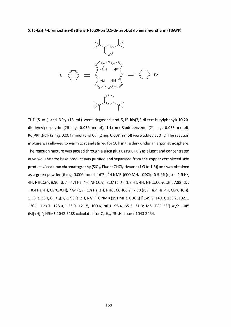
158
5,15-bis((4-bromophenyl)ethynyl)-10,20-bis(3,5-di-tert-butylphenyl)porphyrin (TBAPP)
THF (5 mL) and NEt3 (15 mL) were degassed and 5,15-bis(3,5-di-tert-butylphenyl)-10,20-
diethynylporphyrin (26 mg, 0.036 mmol), 1-bromo8iodobenzene (21 mg, 0.073 mmol),
Pd(PPh3)2Cl2 (3 mg, 0.004 mmol) and CuI (2 mg, 0.008 mmol) were added at 0 oC. The reaction
mixture was allowed to warm to rt and stirred for 18 h in the dark under an argon atmosphere.
The reaction mixture was passed through a silica plug using CHCl3 as eluent and concentrated
in vacuo. The free base product was purified and separated from the copper complexed side
product via column chromatography (SiO2, Eluent CHCl3:Hexane (1:9 to 1:6)) and was obtained
as a green powder (6 mg, 0.006 mmol, 16%). 1H NMR (600 MHz, CDCl3) δ 9.66 (d, J = 4.6 Hz,
4H, NHCCH), 8.90 (d, J = 4.4 Hz, 4H, NHCCH), 8.07 (d, J = 1.8 Hz, 4H, NHCCCCHCCH), 7.88 (d, J
= 8.4 Hz, 4H, CBrCHCH), 7.84 (t, J = 1.8 Hz, 2H, NHCCCCHCCH), 7.70 (d, J = 8.4 Hz, 4H, CBrCHCH),
1.56 (s, 36H, C(CH3)3), -1.93 (s, 2H, NH); 13C NMR (151 MHz, CDCl3) δ 149.2, 140.3, 133.2, 132.1,
130.1, 123.7, 123.0, 123.0, 121.5, 100.6, 96.1, 93.4, 35.2, 31.9; MS (TOF ES+) m/z 1045
(M[+H])+; HRMS 1043.3185 calculated for C64H6179Br2N4 found 1043.3434.

159
5,15-bis((4-bromophenyl)ethynyl)-10,20-dimesitylporphyrin (PEMP)
According to a modified procedure by Nowak-Król et al, 3-(4-bromophenyl)propiolaldehyde
(418 mg, 2.0 mmol) and 2,2'-(mesitylmethylene)bis(1H-pyrrole) (529 mg, 2.0 mmol) were
dissolved in THF (100 mL).100 37% HCl (2.0 mL, 23.0 mmol) in H2O (50 mL) was subsequently
added and the reaction mixture was stirred for 3 h. The reaction mixture was diluted with
brine (100 mL) and the intermediate porphyrinogen product was extracted with CHCl3 (3 x 100
mL). The organic fractions were dried over Mg(SO4), filtered and diluted with CHCl3 to a
volume of 500 mL. DDQ (700 mg, 3.1 mmol) was added and the reaction mixture was stirred
for 1 h. The reaction mixture was concentrated in vacuo and purified via column
chromatography (SiO2, Eluent CHCl3). The relevant fractions were combined, concentrated in
vacuo and washed with MeOH and hexane to yield a shiny, dark green powder (2 mg, 0.02
mmol, 1%). 1H NMR (300 MHz, CDCl3) δ 9.58 (d, J = 4.7 Hz, 4H, NHCCH), 8.68 (d, J = 4.9 Hz, 4H,
NHCCH), 7.86 (d, J = 8.4 Hz, 4H, CBrCHCH), 7.70 (d, J = 8.4 Hz, 4H, CBrCHCH), 7.31 (s, 4H,
NHCCCC(CH3)CHCCH3), 2.65 (s, 6H, NHCCCC(CH3)CHCCH3), 1.86 (s, 12H, NHCCCC(CH3)CHCCH3),
-1.85 (s, 2H, NH); MS (TOF ES+) m/z 903.17, 905.18, 907.19 (M[+H])+; HRMS 903.1698
calculated for C54H4179Br2N4 found 903.1664.
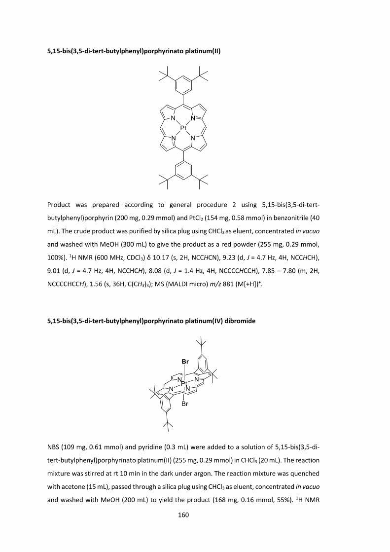
160
5,15-bis(3,5-di-tert-butylphenyl)porphyrinato platinum(II)
Product was prepared according to general procedure 2 using 5,15-bis(3,5-di-tert-
butylphenyl)porphyrin (200 mg, 0.29 mmol) and PtCl2 (154 mg, 0.58 mmol) in benzonitrile (40
mL). The crude product was purified by silica plug using CHCl3 as eluent, concentrated in vacuo
and washed with MeOH (300 mL) to give the product as a red powder (255 mg, 0.29 mmol,
100%). 1H NMR (600 MHz, CDCl3) δ 10.17 (s, 2H, NCCHCN), 9.23 (d, J = 4.7 Hz, 4H, NCCHCH),
9.01 (d, J = 4.7 Hz, 4H, NCCHCH), 8.08 (d, J = 1.4 Hz, 4H, NCCCCHCCH), 7.85 – 7.80 (m, 2H,
NCCCCHCCH), 1.56 (s, 36H, C(CH3)3); MS (MALDI micro) m/z 881 (M[+H])+.
5,15-bis(3,5-di-tert-butylphenyl)porphyrinato platinum(IV) dibromide
NBS (109 mg, 0.61 mmol) and pyridine (0.3 mL) were added to a solution of 5,15-bis(3,5-di-
tert-butylphenyl)porphyrinato platinum(II) (255 mg, 0.29 mmol) in CHCl3 (20 mL). The reaction
mixture was stirred at rt 10 min in the dark under argon. The reaction mixture was quenched
with acetone (15 mL), passed through a silica plug using CHCl3 as eluent, concentrated in vacuo
and washed with MeOH (200 mL) to yield the product (168 mg, 0.16 mmol, 55%). 1H NMR

161
(600 MHz, CDCl3) δ 10.68 (s, 2H, NCCHCN), 9.55 (d, J = 4.9 Hz, 4H, NCCHCH), 9.30 (d, J = 4.8 Hz,
4H, NCCHCH), 8.15 (d, J = 1.5 Hz, 4H, NCCCCHCCH), 7.90 (s, 2H, NCCCCHCCH), 1.58 (s, J = 5.6
Hz, 36H, C(CH3)3); 13C NMR (151 MHz, CDCl3) δ 149.5, 139.5, 138.6, 137.9, 133.2, 132.3, 130.0,
122.3, 122.0, 106.7, 35.3, 31.9; MS (EI-) m/z 1034, 1036 (M[-3H])+; HRMS 1037.2207 calculated
for C48H5279Br2N4Pt found 1037.2201.
4-((2-Octyldodecyl)oxy)benzaldehyde
4-Hydroxybenzaldehyde (1.0 g, 8.19 mmol), 9-(bromomethyl)nonadecane (2.8 g, 8.19 mmol),
K2CO3 (5.7 g, 40.94 mmol) and DMF (30 mL) were stirred under argon at 105 0C for 18 h. The
reaction mixture was allowed to cool and diluted with brine (50mL). The product was
extracted with Et2O (3 x 50 mL), washed with brine (5 x 50 mL) and concentrated in vacuo to
give a yellow oil (2.4 g, 6.93 mmol, 85%). 1H NMR (600 MHz, CDCl3) δ 9.88 (s, 1H, CHO), 7.83
(d, J = 8.6 Hz, 2H, CHCHCCHO), 7.00 (d, J = 8.6 Hz, 2H, CHCHCCHO), 3.92 (d, J = 5.7 Hz, 2H,
OCH2), 1.84 -1.76 (m, 1H, OCH2CH), 1.49 – 1.21 (m, 30H, CH(C6H12)CH3 and CH(C9H18)CH3), 0.88
(t, J = 7.0 Hz, 6H, CH3); MS (EI-) m/z 402 (M)-; HRMS 402.3492 calculated for C27H46O2 found
402.3491.
1-Bromododecane
NBS (28.7 g, 161.00 mmol) was added in portions to 1-Dodecanol (20.0 g, 107.34 mmol) and
PPh3 (42.2 g, 161.00 mmol) in CH2Cl2 (500 mL) at 0 oC. The reaction mixture was stirred for 2
h. The reaction mixture was quenched with saturated Na2SO3 solution (300 mL), the product
was extracted with CH2Cl2 (3 x 250 mL), dried over MgSO4 and concentrated in vacuo. The
crude product was purified via column chromatography (SiO2, Eluent hexane) and was isolated
as a colourless liquid (23.39 g, 101.87 mmol, 95%). 1H NMR (600 MHz, CDCl3) δ 3.41 (t, J = 6.9
Hz, 2H, BrCH2CH2CH2C8H16CH3), 1.90 – 1.82 (m, 2H, BrCH2CH2CH2C8H16CH3), 1.46 – 1.38 (m, 2H,

162
BrCH2CH2CH2C8H16CH3), 1.35 – 1.21 (m, 16H, BrCH2CH2CH2C8H16CH3), 0.88 (t, J = 7.1 Hz, 3H,
BrCH2CH2CH2C8H16CH3); MS (EI+) m/z 248, 250 (M)+. All spectroscopic data is in accordance
with literature values.193
3,4,5-tris(dodecyloxy)benzaldehyde
1-bromododecane (5.0 g, 20.15 mmol), 3,4,5-Trihydroxybenzaldehyde monohydrate (578 mg,
3.36 mmol), K2CO3 (1.39 g, 10.06 mmol) and KI (33 mg, 0.20 mmol) were dissolved in DMF (20
mL). The reaction mixture was heated at 70 oC for 18 h. The product was extracted with CHCl3
(40 mL) from brine (40 mL) and the organic layer was further washed with brine (3 x 40 mL).
The organic layer was dried over MgSO4, concentrated in vacuo and the product was
recystallised from CHCl3/MeOH (1.27 g, 1.93 mmol, 57%). 1H NMR (600 MHz, CDCl3) δ 9.83 (s,
1H, COH), 7.08 (s, 2H, CHCCOH), 4.07 – 4.02 (m, 6H, OCH2CH2CH2(C7H14)CH3), 1.86 – 1.80 (m,
4H, metaOCH2CH2CH2(C7H14)CH3), 1.78 – 1.72 (m, 2H, paraOCH2CH2CH2(C7H14)CH3), 1.51 – 1.45
(m, 6H, OCH2CH2CH2(C7H14)CH3), 1.39 – 1.22 (m, 42H, OCH2CH2CH2(C7H14)CH3), 0.88 (t, J = 7.0
Hz, 9H, OCH2CH2CH2(C7H14)CH3); MS (CI+) m/z 659 (M[+H])+. All spectroscopic data is in
accordance with literature values.194
3,4,5-tris(hexadecyloxy)benzaldehyde
1-Bromohexadecane (4.58 g, 15.0 mmol), 3,4,5-trihydroxybenzaldehyde monohydrate (430
mg, 2.5 mmol), K2CO3 (1.04 g, 7.5 mmol) and KI (25 mg, 0.15 mmol) were dissolved in DMF (15
mL). The reaction mixture was heated at 70 oC for 64 h. The product was extracted with CHCl3
(40 mL) from brine (40 mL) and the organic layer was further washed with brine (3 x 40 mL).
The organic layer was dried over MgSO4, concentrated in vacuo and the product was
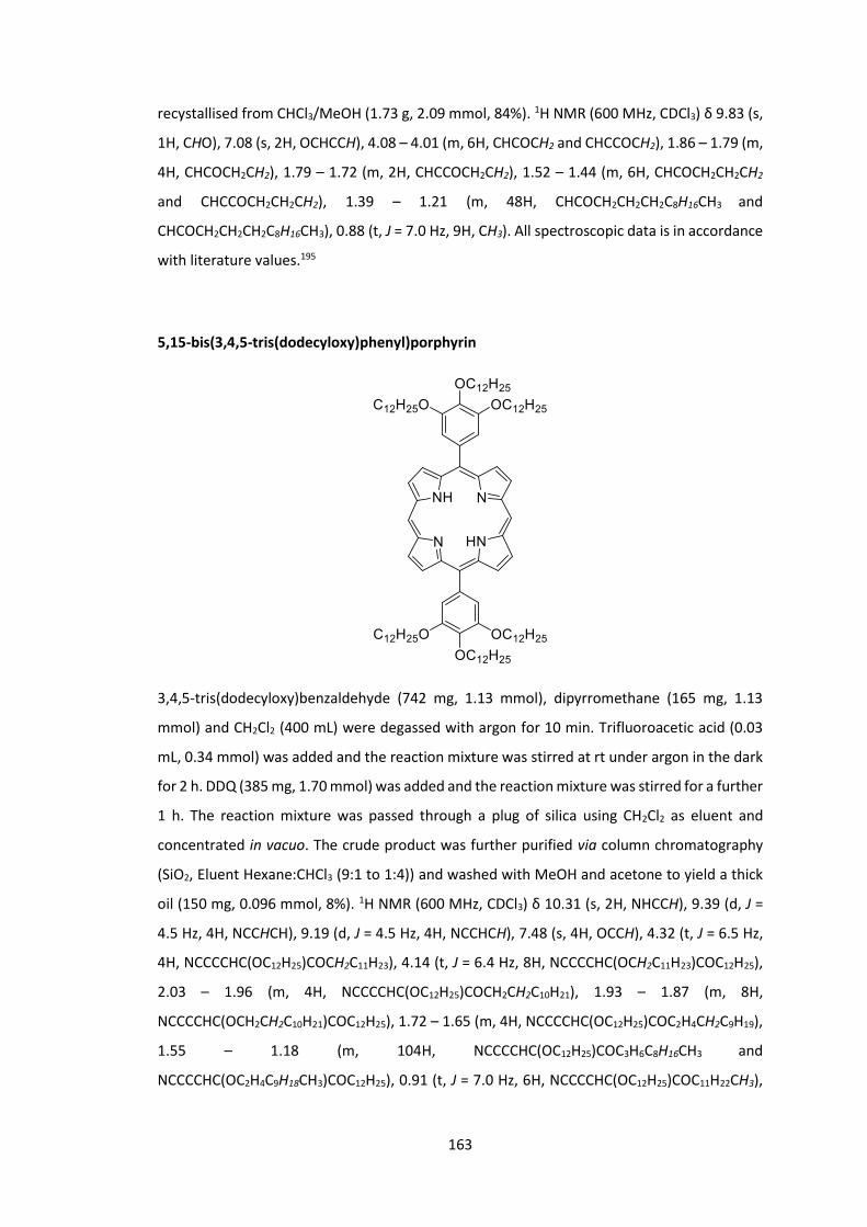
163
recystallised from CHCl3/MeOH (1.73 g, 2.09 mmol, 84%). 1H NMR (600 MHz, CDCl3) δ 9.83 (s,
1H, CHO), 7.08 (s, 2H, OCHCCH), 4.08 – 4.01 (m, 6H, CHCOCH2 and CHCCOCH2), 1.86 – 1.79 (m,
4H, CHCOCH2CH2), 1.79 – 1.72 (m, 2H, CHCCOCH2CH2), 1.52 – 1.44 (m, 6H, CHCOCH2CH2CH2
and CHCCOCH2CH2CH2), 1.39 – 1.21 (m, 48H, CHCOCH2CH2CH2C8H16CH3 and
CHCOCH2CH2CH2C8H16CH3), 0.88 (t, J = 7.0 Hz, 9H, CH3). All spectroscopic data is in accordance
with literature values.195
5,15-bis(3,4,5-tris(dodecyloxy)phenyl)porphyrin
3,4,5-tris(dodecyloxy)benzaldehyde (742 mg, 1.13 mmol), dipyrromethane (165 mg, 1.13
mmol) and CH2Cl2 (400 mL) were degassed with argon for 10 min. Trifluoroacetic acid (0.03
mL, 0.34 mmol) was added and the reaction mixture was stirred at rt under argon in the dark
for 2 h. DDQ (385 mg, 1.70 mmol) was added and the reaction mixture was stirred for a further
1 h. The reaction mixture was passed through a plug of silica using CH2Cl2 as eluent and
concentrated in vacuo. The crude product was further purified via column chromatography
(SiO2, Eluent Hexane:CHCl3 (9:1 to 1:4)) and washed with MeOH and acetone to yield a thick
oil (150 mg, 0.096 mmol, 8%). 1H NMR (600 MHz, CDCl3) δ 10.31 (s, 2H, NHCCH), 9.39 (d, J =
4.5 Hz, 4H, NCCHCH), 9.19 (d, J = 4.5 Hz, 4H, NCCHCH), 7.48 (s, 4H, OCCH), 4.32 (t, J = 6.5 Hz,
4H, NCCCCHC(OC12H25)COCH2C11H23), 4.14 (t, J = 6.4 Hz, 8H, NCCCCHC(OCH2C11H23)COC12H25),
2.03 – 1.96 (m, 4H, NCCCCHC(OC12H25)COCH2CH2C10H21), 1.93 – 1.87 (m, 8H,
NCCCCHC(OCH2CH2C10H21)COC12H25), 1.72 – 1.65 (m, 4H, NCCCCHC(OC12H25)COC2H4CH2C9H19),
1.55 – 1.18 (m, 104H, NCCCCHC(OC12H25)COC3H6C8H16CH3 and
NCCCCHC(OC2H4C9H18CH3)COC12H25), 0.91 (t, J = 7.0 Hz, 6H, NCCCCHC(OC12H25)COC11H22CH3),

164
0.85 (t, J = 7.0 Hz, 12H, NCCCCHC(OC11H22CH3)COC12H25), -3.12 (s, 2H, NH); MS (TOF LD+) m/z
1568 (M)+.
5,15-dibromo-10,20-bis(3,4,5-tris(dodecyloxy)phenyl)porphyrin
To a solution of 5,15-bis(3,4,5-tris(dodecyloxy)phenyl)porphyrin (150 mg, 0.10 mmol) in CHCl3
(15 mL) was added NBS (43 mg, 0.24 mmol) and pyridine (0.1 mL) and the reaction mixture
was stirred for 2 h at rt under argon in the dark. The reaction mixture was concentrated in
vacuo and purified via column chromatography (SiO2, Eluent Hexane:CHCl3 (8:1 to 0:1)) to
yield the product as a thick oil (165 mg, 0.10 mmol, quant) which was taken into the next
reaction without further purification. 1H NMR (300 MHz, CDCl3) δ 9.61 (d, J = 4.6 Hz, 4H,
NCCHCH), 8.95 (d, J = 4.7 Hz, 4H, NCCHCH), 7.37 (s, 4H, OCCH), 4.30 (t, J = 6.5 Hz, 4H,
NCCCCHC(OC12H25)COCH2C11H23), 4.10 (t, J = 6.2 Hz, 8H, NCCCCHC(OCH2C11H23)COC12H25), 2.02
– 1.85 (m, 12H, NCCCCHC(OC12H25)COCH2CH2C10H21 and NCCCCHC(OCH2CH2C10H21)COC12H25),
1.53 – 1.18 (m, 108H, NCCCCHC(OC12H25)COC2H4C9H18CH3 and
NCCCCHC(OC2H4C9H18CH3)COC12H25), 0.95 – 0.80 (m, 18H, CH3), -2.72 (s, 2H, NH); MS (TOF LD+)
m/z 1726 (M)+.

165
5,15-dibromo-10,20-bis(3,4,5-tris(dodecyloxy)phenyl)porphyrinato zinc (II)
5,15-dibromo-10,20-bis(3,4,5-tris(dodecyloxy)phenyl)porphyrin (165 mg, 0.10 mmol) and
Zn(OAc)2 (351 mg, 1.912 mmol) were stirred in CH2Cl2 (30 mL) for 18 h at rt in the dark. The
reaction mixture was concentrated in vacuo and purified via column chromatography (SiO2,
Eluent Hexane:CHCl3 (8:1 to 0:1)) to yield the product as a thick oil (100 mg, 0.06 mmol, 58%). 1H NMR (600 MHz, CDCl3) δ 9.74 (d, J = 4.6 Hz, 4H, NCCHCH), 9.07 (d, J = 4.6 Hz, 4H, NCCHCH),
7.38 (s, 4H, OCCH), 4.31 (t, J = 6.6 Hz, 4H, NCCCCHC(OC12H25)COCH2C11H23), 4.10 (t, J = 6.6 Hz,
8H, NCCCCHC(OCH2C11H23)COC12H25), 2.02 – 1.96 (m, 4H, NCCCCHC(OC12H25)COCH2CH2C10H21),
1.91 – 1.85 (m, 8H, NCCCCHC(OCH2CH2C10H21)COC12H25), 1.71 – 1.65 (m, 4H,
NCCCCHC(OC12H25)COC2H4CH2C9H19), 1.53 – 1.46 (m, 8H, NCCCCHC(OC2H4CH2C9H19)COC12H25),
1.45 – 1.17 (m, 96H, NCCCCHC(OC12H25)COC3H6C8H16CH3 and
NCCCCHC(OC3H6C8H16CH3)COC12H25), 0.91 (t, J = 7.1 Hz, 6H, NCCCCHC(OC12H25)COC11H22CH3),
0.85 (t, J = 7.0 Hz, 12H, NCCCCHC(OC11H22CH3)COC12H25); MS (TOF LD+) m/z 1790 (M)+.
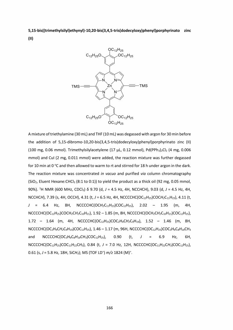
166
5,15-bis((trimethylsilyl)ethynyl)-10,20-bis(3,4,5-tris(dodecyloxy)phenyl)porphyrinato zinc
(II)
A mixture of triethylamine (30 mL) and THF (10 mL) was degassed with argon for 30 min before
the addition of 5,15-dibromo-10,20-bis(3,4,5-tris(dodecyloxy)phenyl)porphyrinato zinc (II)
(100 mg, 0.06 mmol). Trimethylsilylacetylene (17 μL, 0.12 mmol), Pd(PPh3)2Cl2 (4 mg, 0.006
mmol) and CuI (2 mg, 0.011 mmol) were added, the reaction mixture was further degassed
for 10 min at 0 oC and then allowed to warm to rt and stirred for 18 h under argon in the dark.
The reaction mixture was concentrated in vacuo and purified via column chromatography
(SiO2, Eluent Hexane:CHCl3 (8:1 to 0:1)) to yield the product as a thick oil (92 mg, 0.05 mmol,
90%). 1H NMR (600 MHz, CDCl3) δ 9.70 (d, J = 4.5 Hz, 4H, NCCHCH), 9.03 (d, J = 4.5 Hz, 4H,
NCCHCH), 7.39 (s, 4H, OCCH), 4.31 (t, J = 6.5 Hz, 4H, NCCCCHC(OC12H25)COCH2C11H23), 4.11 (t,
J = 6.4 Hz, 8H, NCCCCHC(OCH2C11H23)COC12H25), 2.02 – 1.95 (m, 4H,
NCCCCHC(OC12H25)COCH2CH2C10H21), 1.92 – 1.85 (m, 8H, NCCCCHC(OCH2CH2C10H21)COC12H25),
1.72 – 1.64 (m, 4H, NCCCCHC(OC12H25)COC2H4CH2C9H19), 1.52 – 1.46 (m, 8H,
NCCCCHC(OC2H4CH2C9H19)COC12H25), 1.46 – 1.17 (m, 96H, NCCCCHC(OC12H25)COC3H6C8H16CH3
and NCCCCHC(OC3H6C8H16CH3)COC12H25), 0.90 (t, J = 6.9 Hz, 6H,
NCCCCHC(OC12H25)COC11H22CH3), 0.84 (t, J = 7.0 Hz, 12H, NCCCCHC(OC11H22CH3)COC12H25),
0.61 (s, J = 5.8 Hz, 18H, SiCH3); MS (TOF LD+) m/z 1824 (M)+.

167
5,15-diethynyl-10,20-bis(3,4,5-tris(dodecyloxy)phenyl)porphyrinato zinc (II)
5,15-bis((trimethylsilyl)ethynyl)-10,20-bis(3,4,5-tris(dodecyloxy)phenyl)porphyrinato zinc (II)
(46 mg, 0.025 mmol) was dissolved in CH2Cl2 (20 mL), a 1.0 M solution of TBAF in THF was
added (0.1 mL, 0.1 mmol) was added and the reaction mixture was stirred for 18 h at rt under
argon in the dark. The reaction mixture was concentrated in vacuo and purified via column
chromatography (SiO2, Eluent Hexane:CH2Cl2 (8:1 to 0:1)) to yield the product as a thick oil (42
mg, 0.025 mmol, quant). 1H NMR (600 MHz, CDCl3) δ 9.75 (d, J = 4.6 Hz, 4H, NCCHCH), 9.07 (d,
J = 4.6 Hz, 4H, NCCHCH), 7.40 (s, 4H, OCCH), 4.31 (t, J = 6.7 Hz, 4H,
NCCCCHC(OC12H25)COCH2C11H23), 4.20 (s, 2H, C≡CH), 4.11 (t, J = 6.5 Hz, 8H,
NCCCCHC(OCH2C11H23)COC12H25), 2.02 – 1.96 (m, 4H, NCCCCHC(OC12H25)COCH2CH2C10H21),
1.92 – 1.85 (m, 8H, NCCCCHC(OCH2CH2C10H21)COC12H25), 1.72 – 1.65 (m, 4H,
NCCCCHC(OC12H25)COC2H4CH2C9H19), 1.53 – 1.46 (m, 8H, NCCCCHC(OC2H4CH2C9H19)COC12H25),
1.46 – 1.18 (m, 96H, NCCCCHC(OC12H25)COC3H6C8H16CH3 and
NCCCCHC(OC3H6C8H16CH3)COC12H25), 0.91 (t, J = 7.0 Hz, 6H, NCCCCHC(OC12H25)COC11H22CH3),
0.85 (t, J = 7.1 Hz, 12H, NCCCCHC(OC11H22CH3)COC12H25).
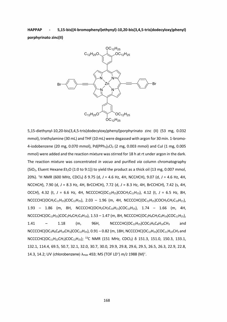
168
HAPPAP - 5,15-bis((4-bromophenyl)ethynyl)-10,20-bis(3,4,5-tris(dodecyloxy)phenyl)
porphyrinato zinc(II)
5,15-diethynyl-10,20-bis(3,4,5-tris(dodecyloxy)phenyl)porphyrinato zinc (II) (53 mg, 0.032
mmol), triethylamine (30 mL) and THF (10 mL) were degassed with argon for 30 min. 1-bromo-
4-iodobenzene (20 mg, 0.070 mmol), Pd(PPh3)2Cl2 (2 mg, 0.003 mmol) and CuI (1 mg, 0.005
mmol) were added and the reaction mixture was stirred for 18 h at rt under argon in the dark.
The reaction mixture was concentrated in vacuo and purified via column chromatography
(SiO2, Eluent Hexane:Et2O (1:0 to 9:1)) to yield the product as a thick oil (13 mg, 0.007 mmol,
20%). 1H NMR (600 MHz, CDCl3) δ 9.75 (d, J = 4.6 Hz, 4H, NCCHCH), 9.07 (d, J = 4.6 Hz, 4H,
NCCHCH), 7.90 (d, J = 8.3 Hz, 4H, BrCCHCH), 7.72 (d, J = 8.3 Hz, 4H, BrCCHCH), 7.42 (s, 4H,
OCCH), 4.32 (t, J = 6.6 Hz, 4H, NCCCCHC(OC12H25)COCH2C11H23), 4.12 (t, J = 6.5 Hz, 8H,
NCCCCHC(OCH2C11H23)COC12H25), 2.03 – 1.96 (m, 4H, NCCCCHC(OC12H25)COCH2CH2C10H21),
1.93 – 1.86 (m, 8H, NCCCCHC(OCH2CH2C10H21)COC12H25), 1.74 – 1.66 (m, 4H,
NCCCCHC(OC12H25)COC2H4CH2C9H19), 1.53 – 1.47 (m, 8H, NCCCCHC(OC2H4CH2C9H19)COC12H25),
1.41 – 1.18 (m, 96H, NCCCCHC(OC12H25)COC3H6C8H16CH3 and
NCCCCHC(OC3H6C8H16CH3)COC12H25), 0.91 – 0.82 (m, 18H, NCCCCHC(OC12H25)COC11H22CH3 and
NCCCCHC(OC11H22CH3)COC12H25); 13C NMR (151 MHz, CDCl3) δ 151.3, 151.0, 150.3, 133.1,
132.1, 114.4, 69.5, 50.7, 32.1, 32.0, 30.7, 30.0, 29.9, 29.8, 29.6, 29.5, 26.5, 26.3, 22.9, 22.8,
14.3, 14.2; UV (chlorobenzene) λmax 453; MS (TOF LD+) m/z 1988 (M)+.

169
F8BT-HAPAPP5 – Poly-2,7-(9,9-dioctylfluorene-alt-4,7-2,1,3-benzothiadiazole)-ran-2,7-(9,9-
dioctylfluorene-alt-4’,4’’-5,15-bis(phenylethynyl)-10,20-bis(3,4,5-
tris(dodecyloxy)phenyl)porphyrinato Zinc (II))
A polymer was synthesised with a weight percentage of 5% porphyrin to benzothiadiazole
moiety (x:y = 19:1).
A solution of 4,7-dibromo-2,1,3-benzothiadiazole (53 mg, 0.181 mmol), 9,9-Dioctyl-9H-
fluorene-2,7-diboronic acid bis(pinacol) ester (118 mg, 0.183 mmol) and 5,15-bis((4-
bromophenyl)ethynyl)-10,20-bis(3,4,5-tris(dodecyloxy)phenyl)porphyrinato zinc (II) (4.5 mg,
0.002 mmol) in toluene (4 mL) and a separate solution of 20% tetraethylammonium hydroxide
in water (3 mL) were degassed for 30 min. Pd(OAc)2 (1 mg, 0.005 mmol) and PPh3 (5 mg, 0.019
mmol) were added to the organic solution which was again degassed for 30 min. The aqueous
solution was added to the organic and the reaction mixture was stirred under argon at 110 oC
for 18 h. The reaction was allowed to cool and the product was precipitated from MeOH and
filtered. The polymer product was then washed with acetone and hexane and extracted with
CHCl3. The polymer was then concentrated in vacuo to a small volume and precipitated from
MeOH (20 mg, 20%). UV (chlorobenzene) λmax 469; GPC (PS): Mn = 10000 Da, Mw = 15000 Da ,
PDI = 1.5.

170
6.4 Synthetic Techniques for Chapter 4
2,7-dibromo-9H-fluoren-9-one
Method 1
To a solution of 2,7-dibromo-9H-fluorene (1.0 g, 3.09 mmol) in AcOH (10 mL) was added CrO3
(1.5 g, 15.0 mmol) in AcOH (10 mL). The reaction mixture was stirred open to air for 42 h at rt.
The reaction was quenched with saturated NaHCO3 solution and the solid yellow product was
filtered and recrystallized twice from a 1:1 mixture of EtOH: toluene (745 mg, 2.2 mmol, 71%). 1H NMR (500 MHz, CDCl3) δ 7.77 (d, J = 1.8 Hz, 2H, COCCH), 7.63 (dd, J = 7.9, 1.8 Hz, 2H,
CBrCHCH), 7.39 (d, J = 7.9 Hz, 2H, CBrCHCH).; MS (CI+) m/z 336, 338 and 340 (M)+. All
spectroscopic data is in accordance with literature values.196
Method 2
Fluorenone (5.00 g, 27.70 mmol) in H2O (70 mL) was heated to 80 oC. Neat Br2 (7.15 mL, 138.70
mmol) was added over 10 min and the reaction mixture was stirred for 10 h. The reaction was
cooled to rt and additional H2O (150 mL) was added followed by saturated Na2SO3 solution
(150 mL). The crude product was filtered and washed with H2O to yield a solid yellow product
(9.25 g, 27.7 mmol, quant) was isolated. All spectra in accordance with previously reported
data.
2,7-dibromo-9,9'-spirobi[fluorene]
Mg (306 mg, 12.6 mmol) and a crystal of I2 were stirred anhydrously with the slow addition of
2-bromobiphenyl (2.2 mL, 12.6 mmol) in THF (15 mL) over 10 min. The reaction was heated to
reflux and stirred for 2 h. The reaction mixture was then cooled to -78 oC and 2,7-dibromo-
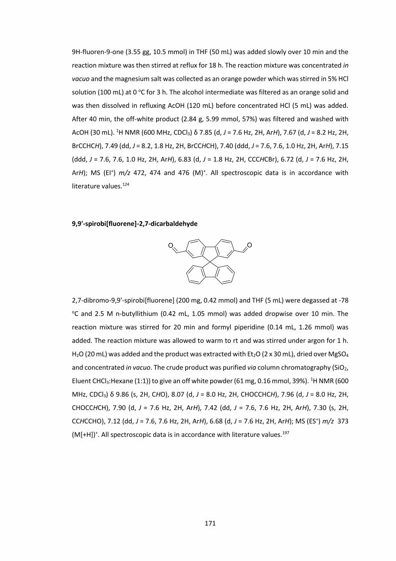
171
9H-fluoren-9-one (3.55 gg, 10.5 mmol) in THF (50 mL) was added slowly over 10 min and the
reaction mixture was then stirred at reflux for 18 h. The reaction mixture was concentrated in
vacuo and the magnesium salt was collected as an orange powder which was stirred in 5% HCl
solution (100 mL) at 0 oC for 3 h. The alcohol intermediate was filtered as an orange solid and
was then dissolved in refluxing AcOH (120 mL) before concentrated HCl (5 mL) was added.
After 40 min, the off-white product (2.84 g, 5.99 mmol, 57%) was filtered and washed with
AcOH (30 mL). 1H NMR (600 MHz, CDCl3) δ 7.85 (d, J = 7.6 Hz, 2H, ArH), 7.67 (d, J = 8.2 Hz, 2H,
BrCCHCH), 7.49 (dd, J = 8.2, 1.8 Hz, 2H, BrCCHCH), 7.40 (ddd, J = 7.6, 7.6, 1.0 Hz, 2H, ArH), 7.15
(ddd, J = 7.6, 7.6, 1.0 Hz, 2H, ArH), 6.83 (d, J = 1.8 Hz, 2H, CCCHCBr), 6.72 (d, J = 7.6 Hz, 2H,
ArH); MS (EI+) m/z 472, 474 and 476 (M)+. All spectroscopic data is in accordance with
literature values.124
9,9'-spirobi[fluorene]-2,7-dicarbaldehyde
2,7-dibromo-9,9'-spirobi[fluorene] (200 mg, 0.42 mmol) and THF (5 mL) were degassed at -78 oC and 2.5 M n-butyllithium (0.42 mL, 1.05 mmol) was added dropwise over 10 min. The
reaction mixture was stirred for 20 min and formyl piperidine (0.14 mL, 1.26 mmol) was
added. The reaction mixture was allowed to warm to rt and was stirred under argon for 1 h.
H2O (20 mL) was added and the product was extracted with Et2O (2 x 30 mL), dried over MgSO4
and concentrated in vacuo. The crude product was purified via column chromatography (SiO2,
Eluent CHCl3:Hexane (1:1)) to give an off white powder (61 mg, 0.16 mmol, 39%). 1H NMR (600
MHz, CDCl3) δ 9.86 (s, 2H, CHO), 8.07 (d, J = 8.0 Hz, 2H, CHOCCHCH), 7.96 (d, J = 8.0 Hz, 2H,
CHOCCHCH), 7.90 (d, J = 7.6 Hz, 2H, ArH), 7.42 (dd, J = 7.6, 7.6 Hz, 2H, ArH), 7.30 (s, 2H,
CCHCCHO), 7.12 (dd, J = 7.6, 7.6 Hz, 2H, ArH), 6.68 (d, J = 7.6 Hz, 2H, ArH); MS (ES+) m/z 373
(M[+H])+. All spectroscopic data is in accordance with literature values.197

172
9,9'-spirobi[fluorene]-2,7-dicarbonitrile
28% ammonium hydroxide solution (0.4 mL) and I2 (89 mg, 0.36 mmol) were added to a
solution of 9,9'-spirobi[fluorene]-2,7-dicarbaldehyde (61 mg, 0.16 mmol) in acetonitrile (2 mL)
and THF (0.5 mL). The reaction mixture was allowed to stir for 64 h. The reaction was
quenched with saturated Na2SO3 solution (20 mL) and the product was extracted with Et2O (2
x 30mL), dried over MgSO4 and concentrated in vacuo to give an off white powder (59 mg,
0.36 mmol, 99%). 1H NMR (500 MHz, CDCl3) δ 7.98 (d, J = 8.0 Hz, 2H, NCCCHCH), 7.89 (d, J =
7.6 Hz, 2H, ArH), 7.72 (dd, J = 8.0, 1.4 Hz, 2H, NCCCHCH), 7.45 (ddd, J = 7.6, 7.6, 1.0 Hz, 2H,
ArH), 7.16 (ddd, J = 7.6, 7.6, 1.0 Hz, 2H, ArH), 7.05 (d, J = 1.4 Hz, 2H, CCHCCN), 6.65 (d, J = 7.6
Hz, 2H, ArH); MS (EI+) m/z 366 (M)+. All spectroscopic data is in accordance with literature
values.198
2’,7’-dibromo-9,9'-spirobi[fluorene]-2,7-dicarbonitrile
Method 1
9,9'-spirobi[fluorene]-2,7-dicarbonitrile (485 mg, 1.32 mmol), FeCl3 (11 mg, 0.07 mmol) and
CH2Cl2 (40 mL) were heated to reflux under anhydrous conditions under an atmosphere of
argon. A solution of Br2 (0.27 mL, 5.28 mmol) in CH2Cl2 (8 mL) was added slowly and the
reaction mixture was stirred at reflux for 7 h. The reaction was quenched with saturated
Na2SO3 solution (70 mL) and the product was extracted with CH2Cl2 (2 x 50 mL), dried over
MgSO4 and concentrated in vacuo. The crude product was purified via column
chromatography (SiO2, Eluent CHCl3:Hexane (1:1)) to give an off white powder that was
further purified by recrystallization from CHCl3 and hexane (88 mg, 0.17 mmol, 13%). 1H NMR
(600 MHz, CDCl3) δ 8.00 (d, J = 8.0 Hz, 2H, NCCCHCH), 7.78 (d, J = 8.0, 2H, NCCCHCH), 7.73 (d,
J = 8.2 Hz, 2H, BrCCHCH), 7.59 (dd, J = 8.2, 1.6 Hz, 2H, BrCCHCH), 7.06 (s, 2H, CCHCCN), 6.77

173
(d, J = 1.6 Hz, 2H, CCHCBr); 13C NMR (151 MHz, CDCl3) δ 148.8, 147.2, 143.9, 139.8, 133.1,
132.5, 128.3, 127.2, 122.6, 122.2, 122.1, 118.3, 113.3, 65.2; MS (EI+) m/z 522, 524 and 526
(M)+; HRMS 521.9367 calculated for C27H1279BrN2 found 521.9362. All spectroscopic data is in
accordance with literature values.198
Method 2
28% ammonium hydroxide solution (6.0 mL) and I2 (765 mg, 3.01 mmol) were added to a
solution of 2',7'-dibromo-9,9'-spirobi[fluorene]-2,7-dicarbaldehyde (729 mg, 1.37 mmol) in
acetonitrile (30 mL) and THF (8 mL). The reaction mixture was allowed to stir for 18 h. The
reaction was quenched with saturated Na2SO3 solution (50 mL) and the product was extracted
with Et2O (2 x 50mL), dried over MgSO4 and concentrated in vacuo to give an off white powder
(489 mg, 0.93 mmol, 68%). All spectra in accordance with previously reported data.
Poly-9,9-dioctyl-9H-fluorene-alt-9,9'-spirobi[fluorene]-2,7-dicarbonitrile
A solution of aliquat 336 (1 drop) in toluene (5 mL) and a separate solution of 1.0 M Na2CO3
(1 mL) were both degassed for 30 min. 2’,7’-dibromo-9,9'-spirobi[fluorene]-2,7-dicarbonitrile
(67 mg, 0.127 mmol) and 2,2'-(9,9-dioctyl-9H-fluorene-2,7-diyl)bis(4,4,5,5-tetramethyl-1,3,2-
dioxaborolane) (82 mg, 0.127 mmol) were placed in a microwave vial and purged with argon.
The solution of aliquat 336 in toluene was added and the reaction mixture was degassed for
40 min. Pd(PPh3)4 (15 mg, 0.013 mmol) was added and the reaction mixture was degassed for
a further 20 min. The 1.0 M Na2CO3 solution (1 mL) was added and the reaction mixture was
heated to 110 oC and stirred for 18 h. The reaction was allowed to cool and the product was
precipitated from MeOH and filtered. The polymer product was then washed with acetone
and hexane and extracted with CHCl3 (89 mg, 93%). GPC (PS): Mn = 5100 Da, Mw = 7800 Da,
PDI = 1.5.

174
2,7-dibromo-9,9-dihexadecyl-9H-fluorene
2,7-dibromofluorene (1.44 g, 4.44 mmol) and 1-bromohexadecane (4.07 mL, 13.33 mmol) in
a 1:1 mixture of 13 M NaOH solution and toluene (30 mL) were degassed for 30 min.
Tetrabutylammonium bromide (13 mg, 0.04 mmol) was added and the reaction was heated
to reflux for 18 h. The reaction was allowed to cool, the organic layer separated and the
aqueous washed with CH2Cl2 (2 x 25 mL). The combined organic fractions were dried over
MgSO4 and concentrated in vacuo to yield a yellow solid which was recrystallized from EtOH
to give off white crystals (1.90 g, 2.46 mmol, 55%). 1H NMR (300 MHz, CDCl3) δ 7.54 – 7.48 (m,
2H, CBrCHCH), 7.47 – 7.41 (m, 4H, CH2CCCH + CBrCHCH), 1.95 – 1.85 (m, 4H, C(CH2C14H28CH3)2),
1.34 – 0.99 (m, 56H, C(CH2C14H28CH3)2), 0.87 (t, J = 6.7 Hz, 6H, C(CH2C14H28CH3)2); 13C NMR (151
MHz, CDCl3) δ 152.7, 139.2, 130.3, 126.3, 121.6, 121.3, 55.8, 40.3, 32.1, 30.00, 29.8, 29.8, 29.8,
29.8, 29.7, 29.7, 29.7, 29.5, 29.3, 23.7, 22.8, 14.3; MS (EI+) m/z 769, 771 and 773 (M)+; HRMS
770.4001 calculated for C45H7279Br2 found 770.4005.
2,7-dibromo-9,9-dihexadecyl-9H-fluorene
2,7-dibromo-9,9-dihexadecyl-9H-fluorene (900 mg, 1.16 mmol), bis(pinacolato)diboron (886
mg, 3.49 mmol), [1,1′-Bis(diphenylphosphino)ferrocene]dichloropalladium(II), complex with
dichloromethane (65 mg, 0.08 mmol), potassium acetate (457 mg, 4.66 mmol) and DMF (50
mL) were degassed with argon for 10 min and then stirred at 80 oC for 64 h. The reaction
mixture was poured into H2O (150 mL) and the product was extracted with CH2Cl2 (2 x 100
mL). The organic fraction was washed with brine (4 x 150 mL), dried over MgSO4 and
concentrated in vacuo. The crude product was purified via column chromatography (SiO2,
Eluent CHCl3:Hexane (1:3)) to give a clear liquid that solidified to white crystals upon standing
(1.00 g, 1.15 mmol, 99%). 1H NMR (600 MHz, CDCl3) δ 7.81 (d, J = 7.6 Hz, 2H, CBrCHCH), 7.75
(s, 2H, CH2CCCH), 7.72 (d, J = 7.6 Hz, 2H, CBrCHCH), 2.03 – 1.97 (m, 4H, C(CH2C14H28CH3)2), 1.39
(s, 24H, BOCCH3), 1.34 – 1.17 (m, 56H, C(CH2C14H28CH3)2), 0.89 (t, J = 7.0 Hz, 6H,

175
C(CH2C14H28CH3)2); 13C NMR (151 MHz, CDCl3) δ 150.6, 144.0, 133.8, 129.0, 119.5, 83.8, 55.3,
40.3, 32.1, 31.7, 30.1, 29.8, 29.7, 29.5, 29.4, 25.0, 22.8, 14.3; MS (EI+) m/z 890 (M+Na)+; HRMS
889.7392 calculated for C57H96B2NaO4 found 889.8323.
2-bromo-4,4'-dimethyl-1,1'-biphenyl
4,4′-Dimethylbiphenyl (4.0 g, 21.9 mmol), a crystal of I2 and dry CH2Cl2 (40 mL) were stirred
anhydrously for 30 min at 0 oC. Br2 (1.36 mL, 26.3 mmol) was added and the reaction mixture
was stirred at 0 oC for 3 h. Na2SO3 solution (50 mL) was added and the organic layer was
separated and extracted with further Na2SO3 solution (2 x 50 mL). The organic layer was dried
over MgSO4 and concentrated in vacuo. Product (5.73 g, 21.9 mmol, 100%) was taken into the
next reaction without further purification. 1H NMR (600 MHz, CDCl3) δ 7.51 (d, J = 0.8 Hz, 1H,
BrCCH), 7.31 (d, J = 8.1 Hz, 2H, MeCCHCH), 7.24 (d, J = 8.1 Hz, 2H, MeCCHCH), 7.22 (d, J = 7.7
Hz, 1H, BrCCHC(Me)CHCH), 7.16 (dd, J = 7.7 Hz, 0.8 Hz, 1H, BrCCHC(Me)CH); MS (ES+) m/z 260,
262 (M)+; HRMS 260.0201 calculated for C14H1379Br found 260.0199. All spectroscopic data is
in accordance with literature values.199
2,7-dibromo-2',7'-dimethyl-9,9'-spirobi[fluorene]
Mg (537 mg, 22.1 mmol) and a crystal of I2 were placed under argon and 2-bromo-4,4'-
dimethyl-1,1'-biphenyl (5.77 g, 22.1 mmol) in THF (40 mL) was added slowly at rt. The solution
was heated to 85 oC for 1 h and was then cooled to -78 oC and 2,7-dibromo-9H-fluoren-9-one
(3.40 g, 10.1 mmol) in THF (100 mL) was added slowly. The reaction was heated to 85 oC and
stirred for 18 h. The reaction mixture was then concentrated in vacuo and 5% HCl solution was
added and stirred for 2 h. The HCl solution was then decanted off and the remaining solid was
dissolved in AcOH (100 mL) at 120 oC. Concentrated HCl (2 drops) was added and the solution
was allowed to cool to rt. The product was filtered off as a white powder (4.26 g, 8.47 mmol,
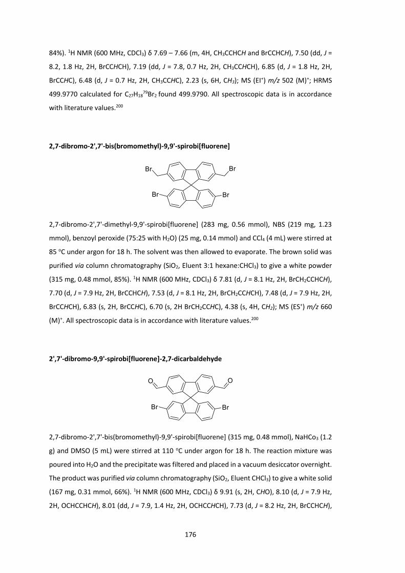
176
84%). 1H NMR (600 MHz, CDCl3) δ 7.69 – 7.66 (m, 4H, CH3CCHCH and BrCCHCH), 7.50 (dd, J =
8.2, 1.8 Hz, 2H, BrCCHCH), 7.19 (dd, J = 7.8, 0.7 Hz, 2H, CH3CCHCH), 6.85 (d, J = 1.8 Hz, 2H,
BrCCHC), 6.48 (d, J = 0.7 Hz, 2H, CH3CCHC), 2.23 (s, 6H, CH3); MS (EI+) m/z 502 (M)+; HRMS
499.9770 calculated for C27H1879Br2 found 499.9790. All spectroscopic data is in accordance
with literature values.200
2,7-dibromo-2',7'-bis(bromomethyl)-9,9'-spirobi[fluorene]
2,7-dibromo-2',7'-dimethyl-9,9'-spirobi[fluorene] (283 mg, 0.56 mmol), NBS (219 mg, 1.23
mmol), benzoyl peroxide (75:25 with H2O) (25 mg, 0.14 mmol) and CCl4 (4 mL) were stirred at
85 oC under argon for 18 h. The solvent was then allowed to evaporate. The brown solid was
purified via column chromatography (SiO2, Eluent 3:1 hexane:CHCl3) to give a white powder
(315 mg, 0.48 mmol, 85%). 1H NMR (600 MHz, CDCl3) δ 7.81 (d, J = 8.1 Hz, 2H, BrCH2CCHCH),
7.70 (d, J = 7.9 Hz, 2H, BrCCHCH), 7.53 (d, J = 8.1 Hz, 2H, BrCH2CCHCH), 7.48 (d, J = 7.9 Hz, 2H,
BrCCHCH), 6.83 (s, 2H, BrCCHC), 6.70 (s, 2H BrCH2CCHC), 4.38 (s, 4H, CH2); MS (ES+) m/z 660
(M)+. All spectroscopic data is in accordance with literature values.200
2',7'-dibromo-9,9'-spirobi[fluorene]-2,7-dicarbaldehyde
2,7-dibromo-2',7'-bis(bromomethyl)-9,9'-spirobi[fluorene] (315 mg, 0.48 mmol), NaHCo3 (1.2
g) and DMSO (5 mL) were stirred at 110 oC under argon for 18 h. The reaction mixture was
poured into H2O and the precipitate was filtered and placed in a vacuum desiccator overnight.
The product was purified via column chromatography (SiO2, Eluent CHCl3) to give a white solid
(167 mg, 0.31 mmol, 66%). 1H NMR (600 MHz, CDCl3) δ 9.91 (s, 2H, CHO), 8.10 (d, J = 7.9 Hz,
2H, OCHCCHCH), 8.01 (dd, J = 7.9, 1.4 Hz, 2H, OCHCCHCH), 7.73 (d, J = 8.2 Hz, 2H, BrCCHCH),

177
7.56 (dd, J = 8.2, 1.8 Hz, 2H, BrCCHCH), 7.31 (d, J = 1.4 Hz, 2H, OCHCCHC), 6.79 (d, J = 1.8 Hz,
2H, BrCCHC); MS (EI+) m/z 530 (M)+; HRMS 529.9335 calculated for C27H1479Br2O2 found
529.9338. All spectroscopic data is in accordance with literature values.200
SFCN – Poly-2,7-(9,9-dihexadecyl-9H-fluoren-2-yl)-alt-2,7-(9,9'-spirobi[fluorene]-2’,7’-
dicarbonitrile)
A solution of 2’,7’-dibromo-9,9'-spirobi[fluorene]-2,7-dicarbonitrile (132 mg, 0.253 mmol) and
2,2'-(9,9-dihexadecyl-9H-fluorene-2,7-diyl)bis(4,4,5,5-tetramethyl-1,3,2-dioxaborolane) (219
mg, 0.253 mmol) in toluene (4 mL) and a separate solution of 20% tetraethylammonium
hydroxide in water (3 mL) were degassed for 30 min. Pd(OAc)2 (1 mg, 0.005 mmol) and PPh3
(7 mg, 0.025 mmol) were added to the organic solution which was again degassed for 30 min.
The aqueous solution was added to the organic and the reaction mixture was stirred under
argon at 110 oC for 18 h. The reaction was allowed to cool and the product was precipitated
from MeOH and filtered. The polymer product was then washed with acetone and hexane and
extracted with CHCl3 (253 mg, 100%). UV (chlorobenzene) λmax 385, (Thin film) λmax 385; GPC
(PS): Mn = 20000 Da, Mw = 29000 Da, PDI = 1.5.
SFH – Poly-2,7-(9,9-dihexadecyl-9H-fluoren-2-yl)-alt-2,7-(9,9'-spirobi[fluorene])
A solution of 2’,7’-dibromo-9,9'-spirobi[fluorene] (55 mg, 0.117 mmol) and 2,2'-(9,9-
dihexadecyl-9H-fluorene-2,7-diyl)bis(4,4,5,5-tetramethyl-1,3,2-dioxaborolane) (101 mg,
0.117 mmol) in toluene (4 mL) and a separate solution of 20% tetraethylammonium hydroxide
in water (3 mL) were degassed for 30 min. Pd(OAc)2 (1 mg, 0.005 mmol) and PPh3 (7 mg, 0.025
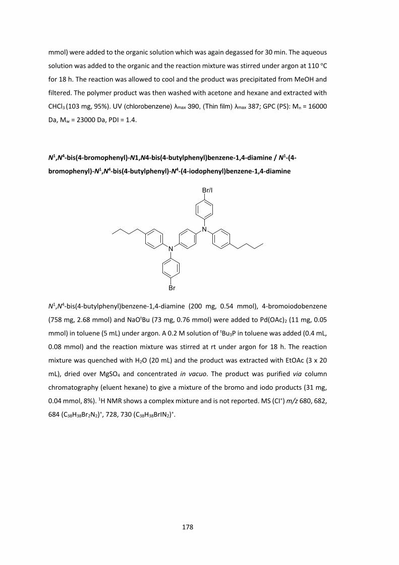
178
mmol) were added to the organic solution which was again degassed for 30 min. The aqueous
solution was added to the organic and the reaction mixture was stirred under argon at 110 oC
for 18 h. The reaction was allowed to cool and the product was precipitated from MeOH and
filtered. The polymer product was then washed with acetone and hexane and extracted with
CHCl3 (103 mg, 95%). UV (chlorobenzene) λmax 390, (Thin film) λmax 387; GPC (PS): Mn = 16000
Da, Mw = 23000 Da, PDI = 1.4.
N1,N4-bis(4-bromophenyl)-N1,N4-bis(4-butylphenyl)benzene-1,4-diamine / N1-(4-
bromophenyl)-N1,N4-bis(4-butylphenyl)-N4-(4-iodophenyl)benzene-1,4-diamine
N1,N4-bis(4-butylphenyl)benzene-1,4-diamine (200 mg, 0.54 mmol), 4-bromoiodobenzene
(758 mg, 2.68 mmol) and NaOtBu (73 mg, 0.76 mmol) were added to Pd(OAc)2 (11 mg, 0.05
mmol) in toluene (5 mL) under argon. A 0.2 M solution of tBu3P in toluene was added (0.4 mL,
0.08 mmol) and the reaction mixture was stirred at rt under argon for 18 h. The reaction
mixture was quenched with H2O (20 mL) and the product was extracted with EtOAc (3 x 20
mL), dried over MgSO4 and concentrated in vacuo. The product was purified via column
chromatography (eluent hexane) to give a mixture of the bromo and iodo products (31 mg,
0.04 mmol, 8%). 1H NMR shows a complex mixture and is not reported. MS (CI+) m/z 680, 682,
684 (C38H38Br2N2)+, 728, 730 (C38H38BrIN2)+.

179
4-heptyl-N-phenylaniline
CuI (27 mg, 0.14 mmol), K2CO3 (193 mg, 1.40 mmol) and L-proline (16 mg, 0.14 mmol) were
dissolved in DMSO (5 mL) and degassed with argon. 4-heptylaniline (200 mg, 1.05 mmol) and
iodobenzene (142 mg, 0.70 mmol) were added and the reaction mixture was stirred at 90 oC
under argon for 18 h. The reaction mixture was poured into brine (15 mL) and extracted with
EtOAc (2 x 20 mL). The combined organic fractions were dried over MgSO4 and concentrated
in vacuo. The product was purified via column chromatography (eluent 3:1 hexane:CHCl3) to
give a clear oil (100 mg, 0.37 mmol, 36%). 1H NMR (600 MHz, CDCl3) δ 7.25 (d, J = 8.3 Hz, 2H,
NCHCHCC7H15), 7.10 (d, J = 8.3 Hz, 2H, NCHCHCC7H15), 7.08 – 7.03 (m, 4H, NCCHCHCH and
NCCHCHCH), 6.92 (t, J = 6.9 Hz, 1H, NCCHCHCH), 2.59 – 2.53 (t, J = 7.8 Hz, 2H, CH3C4H8CH2CH2),
1.59 (m, 2H, CH3C4H8CH2CH2), 1.36 – 1.23 (m, 8H, CH3C4H8CH2CH2), 0.89 (t, J = 7.1 Hz, 3H, CH3).
4-bromo-N,N-diphenylaniline
Triphenylamine (1.0 g, 4.08 mmol), NBS (726 mg, 4.08 mmol) and CCl4 (10 mL) were stirred
under argon at 80 oC for 5 h. The succinimide side product was filtered and the solvent was
allowed to evaporate in an isolated fume hood. The grey solid was recrystallized from EtOH
to give white crystals (762 mg, 2.35 mmol, 58%). 1H NMR (600 MHz, DMSO) δ 7.43 (d, J = 8.9
Hz, 2H, BrCCH), 7.32 (dd, J = 8.5, 7.4 Hz, 4H, NCCHCHCH), 7.08 (t, J = 7.4 Hz, 2H, NCCHCHCH),
7.02 (d, J = 8.5, 4H, NCCHCHCH), 6.89 (d, J = 8.9 Hz, 2H, BrCCHCH).

180
Tris(4-bromophenyl)amine
NBS (2.4 g, 13.45 mmol) was added to Triphenylamine (1.0 g, 4.08 mmol) in dry DMF (15 mL)
at 0 oC and was then allowed to warm to rt and stirred for 18 h. The product was extracted
with Et2O and brine and the organic fractions were dried over MgSO4 and concentrated in
vacuo. The obtained brown oil was left for 64 h, and white crystals appeared and were filtered
(656 mg, 1.36 mmol, 33%). 1H NMR (600 MHz, CDCl3) δ 7.36 (d, J = 8.8 Hz, 6H, BrCCH), 6.93 (d,
J = 8.8 Hz, 6H, BrCCHCH); MS (ES+) m/z 479, 481, 483, 485 (M)+; HRMS 478.8514 calculated for
C18H1279Br3N found 478.8513. All spectroscopic data is in accordance with literature values.201
4-bromo-N-(4-bromophenyl)-N-phenylaniline
To a solution of triphenylamine (5.0 g, 20.35 mmol) in DMF (60 mL) was added NBS (7.26 g,
40.70 mmol) in DMF (80 mL) at 0 oC. The reaction mixture was stirred for 4 h and then
concentrated in vacuo. The product was purified via column chromatography (SiO2, Eluent
Hexane) to yield a waxy colourless solid (7.30 g, 18.11 mmol, 89%). 1H NMR (600 MHz, DMSO)
δ 7.45 (d, J = 8.7 Hz, 4H, BrCCH), 7.35 – 7.32 (m, 2H, NCCHCHCH), 7.11 (t, J = 7.4 Hz, 1H,
NCCHCHCH), 7.04 (d, J = 8.5 Hz, 2H, NCCHCHCH), 6.93 (d, J = 8.9 Hz, 4H, BrCCHCH); MS (EI+)
m/z 401, 403, 405 (M)+; HRMS 400.9409 calculated for C18H13N79Br2 found 400.9409. All
spectroscopic data is in accordance with literature values.201

181
2-octyldodecanoic acid
To a solution of periodic acid (7.56 g, 33.16 mmol) in acetonitrile (45 mL) was added 2-
octyldodecan-1-ol (4.5 g, 15.07 mmol) at 0 oC. The mixture was stirred for 15 minutes before
the slow addition of a solution of pyridinium chlorochromate (65 mg) in acetonitrile (8 mL).
The reaction mixture was allowed to warm to rt and stirred for 18 h. The reaction mixture was
quenched with NaHCO3 solution (100 mL) and the product was extracted with EtOAc (3 x 100
mL), dried over MgSO4 and concentrated in vacuo. The product was placed in a vacuum
desiccator for 2 h to give a white powder (4.35 g, 13.92 mmol, 92%). 1H NMR (600 MHz, CDCl3)
δ 2.35 (m, 1H, CHCOOH), 1.67 – 1.58 (m, 2H, CH2CHCOOH), 1.50 – 1.43 (m, 2H, CH2CHCOOH),
1.35 – 1.21 (m, 28H, CH3C8H16CH2CH(COOH)CH2C6H12CH3), 0.88 (t, J = 7.0 Hz, 6H, CH3); MS (EI+)
m/z 312 (M)+; HRMS 312.3023 calculated for C20H40O2 found 312.3022. All spectroscopic data
is in accordance with literature values.202
2-octyldodecanoyl chloride
2-octyldodecanoic acid (4.00 g, 12.80 mmol) in CH2Cl2 (12 mL) was treated with SOCl2 (2.80
mL, 38.40 mmol) then DMF (0.2 mL) under an atmosphere of argon at rt. The reaction mixture
was stirred for 18 h. The reaction mixture was then concentrated in vacuo and used directly
in the next reaction without further purification or analysis.
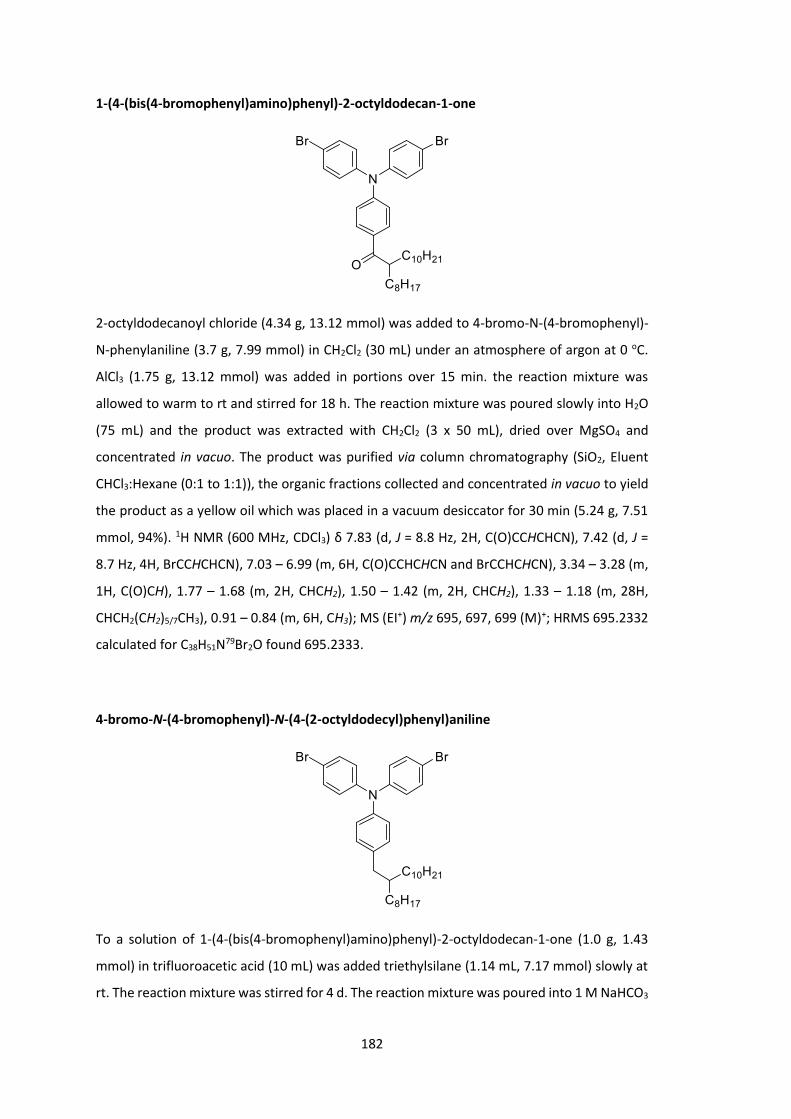
182
1-(4-(bis(4-bromophenyl)amino)phenyl)-2-octyldodecan-1-one
2-octyldodecanoyl chloride (4.34 g, 13.12 mmol) was added to 4-bromo-N-(4-bromophenyl)-
N-phenylaniline (3.7 g, 7.99 mmol) in CH2Cl2 (30 mL) under an atmosphere of argon at 0 oC.
AlCl3 (1.75 g, 13.12 mmol) was added in portions over 15 min. the reaction mixture was
allowed to warm to rt and stirred for 18 h. The reaction mixture was poured slowly into H2O
(75 mL) and the product was extracted with CH2Cl2 (3 x 50 mL), dried over MgSO4 and
concentrated in vacuo. The product was purified via column chromatography (SiO2, Eluent
CHCl3:Hexane (0:1 to 1:1)), the organic fractions collected and concentrated in vacuo to yield
the product as a yellow oil which was placed in a vacuum desiccator for 30 min (5.24 g, 7.51
mmol, 94%). 1H NMR (600 MHz, CDCl3) δ 7.83 (d, J = 8.8 Hz, 2H, C(O)CCHCHCN), 7.42 (d, J =
8.7 Hz, 4H, BrCCHCHCN), 7.03 – 6.99 (m, 6H, C(O)CCHCHCN and BrCCHCHCN), 3.34 – 3.28 (m,
1H, C(O)CH), 1.77 – 1.68 (m, 2H, CHCH2), 1.50 – 1.42 (m, 2H, CHCH2), 1.33 – 1.18 (m, 28H,
CHCH2(CH2)5/7CH3), 0.91 – 0.84 (m, 6H, CH3); MS (EI+) m/z 695, 697, 699 (M)+; HRMS 695.2332
calculated for C38H51N79Br2O found 695.2333.
4-bromo-N-(4-bromophenyl)-N-(4-(2-octyldodecyl)phenyl)aniline
To a solution of 1-(4-(bis(4-bromophenyl)amino)phenyl)-2-octyldodecan-1-one (1.0 g, 1.43
mmol) in trifluoroacetic acid (10 mL) was added triethylsilane (1.14 mL, 7.17 mmol) slowly at
rt. The reaction mixture was stirred for 4 d. The reaction mixture was poured into 1 M NaHCO3
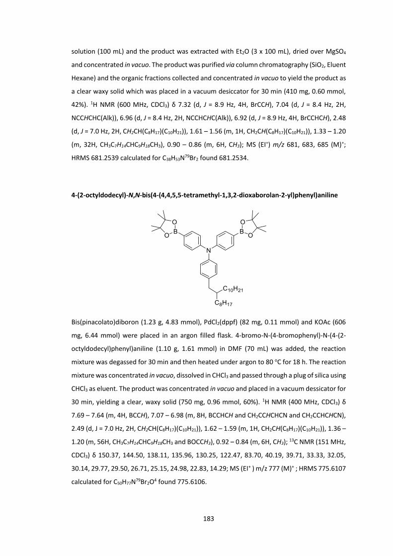
183
solution (100 mL) and the product was extracted with Et2O (3 x 100 mL), dried over MgSO4
and concentrated in vacuo. The product was purified via column chromatography (SiO2, Eluent
Hexane) and the organic fractions collected and concentrated in vacuo to yield the product as
a clear waxy solid which was placed in a vacuum desiccator for 30 min (410 mg, 0.60 mmol,
42%). 1H NMR (600 MHz, CDCl3) δ 7.32 (d, J = 8.9 Hz, 4H, BrCCH), 7.04 (d, J = 8.4 Hz, 2H,
NCCHCHC(Alk)), 6.96 (d, J = 8.4 Hz, 2H, NCCHCHC(Alk)), 6.92 (d, J = 8.9 Hz, 4H, BrCCHCH), 2.48
(d, J = 7.0 Hz, 2H, CH2CH(C8H17)(C10H21)), 1.61 – 1.56 (m, 1H, CH2CH(C8H17)(C10H21)), 1.33 – 1.20
(m, 32H, CH3C7H14CHC9H18CH3), 0.90 – 0.86 (m, 6H, CH3); MS (EI+) m/z 681, 683, 685 (M)+;
HRMS 681.2539 calculated for C38H53N79Br2 found 681.2534.
4-(2-octyldodecyl)-N,N-bis(4-(4,4,5,5-tetramethyl-1,3,2-dioxaborolan-2-yl)phenyl)aniline
Bis(pinacolato)diboron (1.23 g, 4.83 mmol), PdCl2(dppf) (82 mg, 0.11 mmol) and KOAc (606
mg, 6.44 mmol) were placed in an argon filled flask. 4-bromo-N-(4-bromophenyl)-N-(4-(2-
octyldodecyl)phenyl)aniline (1.10 g, 1.61 mmol) in DMF (70 mL) was added, the reaction
mixture was degassed for 30 min and then heated under argon to 80 oC for 18 h. The reaction
mixture was concentrated in vacuo, dissolved in CHCl3 and passed through a plug of silica using
CHCl3 as eluent. The product was concentrated in vacuo and placed in a vacuum dessicator for
30 min, yielding a clear, waxy solid (750 mg, 0.96 mmol, 60%). 1H NMR (400 MHz, CDCl3) δ
7.69 – 7.64 (m, 4H, BCCH), 7.07 – 6.98 (m, 8H, BCCHCH and CH2CCHCHCN and CH2CCHCHCN),
2.49 (d, J = 7.0 Hz, 2H, CH2CH(C8H17)(C10H21)), 1.62 – 1.59 (m, 1H, CH2CH(C8H17)(C10H21)), 1.36 –
1.20 (m, 56H, CH3C7H14CHC9H18CH3 and BOCCH3), 0.92 – 0.84 (m, 6H, CH3); 13C NMR (151 MHz,
CDCl3) δ 150.37, 144.50, 138.11, 135.96, 130.25, 122.47, 83.70, 40.19, 39.71, 33.33, 32.05,
30.14, 29.77, 29.50, 26.71, 25.15, 24.98, 22.83, 14.29; MS (EI+ ) m/z 777 (M)+ ; HRMS 775.6107
calculated for C50H77N79Br2O4 found 775.6106.

184
ASFCN – Poly-4’,4’’-(4-(2-octyldodecyl)-N,N-diphenylaniline)-alt-2,7-(9,9'-spirobi[fluorene]-
2’,7’-dicarbonitrile)
A solution of 2’,7’-dibromo-9,9'-spirobi[fluorene]-2,7-dicarbonitrile (191 mg, 0.365 mmol) and
4-(2-octyldodecyl)-N,N-bis(4-(4,4,5,5-tetramethyl-1,3,2-dioxaborolan-2-yl)phenyl)aniline
(284 mg, 0.365 mmol) in toluene (8 mL) and a separate solution of 20% tetraethylammonium
hydroxide in water (7 mL) were degassed for 30 min. Pd(OAc)2 (2 mg, 0.007 mmol) and PPh3
(10 mg, 0.038 mmol) were added to the organic solution which was again degassed for 30
min. The aqueous solution was added to the organic and the reaction mixture was stirred
under argon at 110 oC for 3 d. The reaction was allowed to cool and the product was
precipitated from MeOH and filtered. The polymer product was then washed with acetone
and hexane and extracted with CHCl3 (280 mg, 86%). UV (chlorobenzene) λmax 396, (Thin film)
λmax 400; GPC (PS): Mn = 23000 Da, Mw = 49000 Da, PDI = 2.1.
ASFH - Poly-4’,4’’-(4-(2-octyldodecyl)-N,N-diphenylaniline)-alt-2,7-(9,9'-spirobi[fluorene])
A solution of 2’,7’-dibromo-9,9'-spirobi[fluorene] (169 mg, 0.357 mmol) and 4-(2-
octyldodecyl)-N,N-bis(4-(4,4,5,5-tetramethyl-1,3,2-dioxaborolan-2-yl)phenyl)aniline (278 mg,
0.357 mmol) in toluene (8 mL) and a separate solution of 20% tetraethylammonium hydroxide
in water (7 mL) were degassed for 30 min. Pd(OAc)2 (2 mg, 0.007 mmol) and PPh3 (9 mg, 0.036
mmol) were added to the organic solution which was again degassed for 30 min. The aqueous

185
solution was added to the organic and the reaction mixture was stirred under argon at 110 oC
for 3 d. The reaction was allowed to cool and the product was precipitated from MeOH and
filtered. The polymer product was then washed with acetone and hexane and extracted with
CHCl3 (220 mg, 73%). UV (chlorobenzene) λmax 387, (Thin film) λmax 394; GPC (PS): Mn = 18000
Da, Mw = 31000 Da, PDI = 1.7.
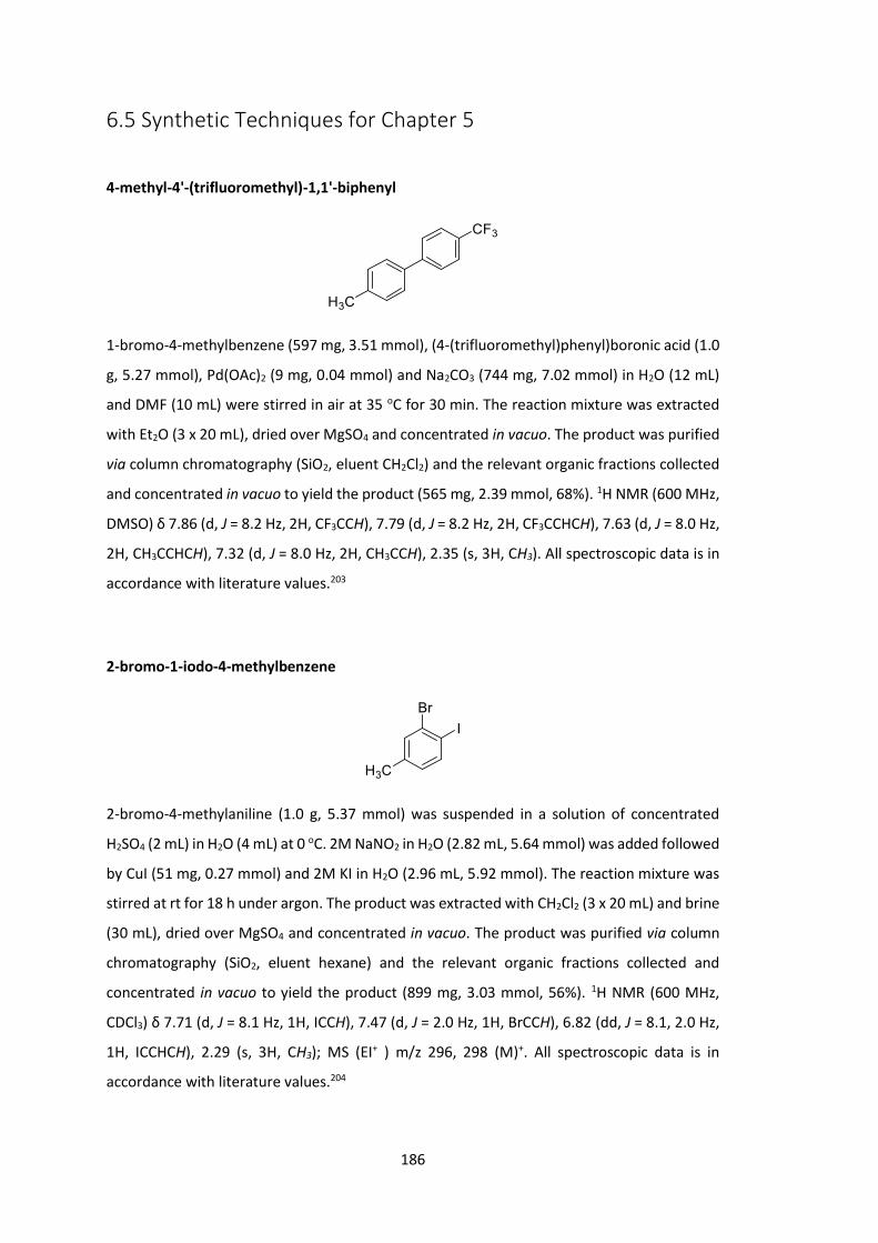
186
6.5 Synthetic Techniques for Chapter 5
4-methyl-4'-(trifluoromethyl)-1,1'-biphenyl
1-bromo-4-methylbenzene (597 mg, 3.51 mmol), (4-(trifluoromethyl)phenyl)boronic acid (1.0
g, 5.27 mmol), Pd(OAc)2 (9 mg, 0.04 mmol) and Na2CO3 (744 mg, 7.02 mmol) in H2O (12 mL)
and DMF (10 mL) were stirred in air at 35 oC for 30 min. The reaction mixture was extracted
with Et2O (3 x 20 mL), dried over MgSO4 and concentrated in vacuo. The product was purified
via column chromatography (SiO2, eluent CH2Cl2) and the relevant organic fractions collected
and concentrated in vacuo to yield the product (565 mg, 2.39 mmol, 68%). 1H NMR (600 MHz,
DMSO) δ 7.86 (d, J = 8.2 Hz, 2H, CF3CCH), 7.79 (d, J = 8.2 Hz, 2H, CF3CCHCH), 7.63 (d, J = 8.0 Hz,
2H, CH3CCHCH), 7.32 (d, J = 8.0 Hz, 2H, CH3CCH), 2.35 (s, 3H, CH3). All spectroscopic data is in
accordance with literature values.203
2-bromo-1-iodo-4-methylbenzene
2-bromo-4-methylaniline (1.0 g, 5.37 mmol) was suspended in a solution of concentrated
H2SO4 (2 mL) in H2O (4 mL) at 0 oC. 2M NaNO2 in H2O (2.82 mL, 5.64 mmol) was added followed
by CuI (51 mg, 0.27 mmol) and 2M KI in H2O (2.96 mL, 5.92 mmol). The reaction mixture was
stirred at rt for 18 h under argon. The product was extracted with CH2Cl2 (3 x 20 mL) and brine
(30 mL), dried over MgSO4 and concentrated in vacuo. The product was purified via column
chromatography (SiO2, eluent hexane) and the relevant organic fractions collected and
concentrated in vacuo to yield the product (899 mg, 3.03 mmol, 56%). 1H NMR (600 MHz,
CDCl3) δ 7.71 (d, J = 8.1 Hz, 1H, ICCH), 7.47 (d, J = 2.0 Hz, 1H, BrCCH), 6.82 (dd, J = 8.1, 2.0 Hz,
1H, ICCHCH), 2.29 (s, 3H, CH3); MS (EI+ ) m/z 296, 298 (M)+. All spectroscopic data is in
accordance with literature values.204
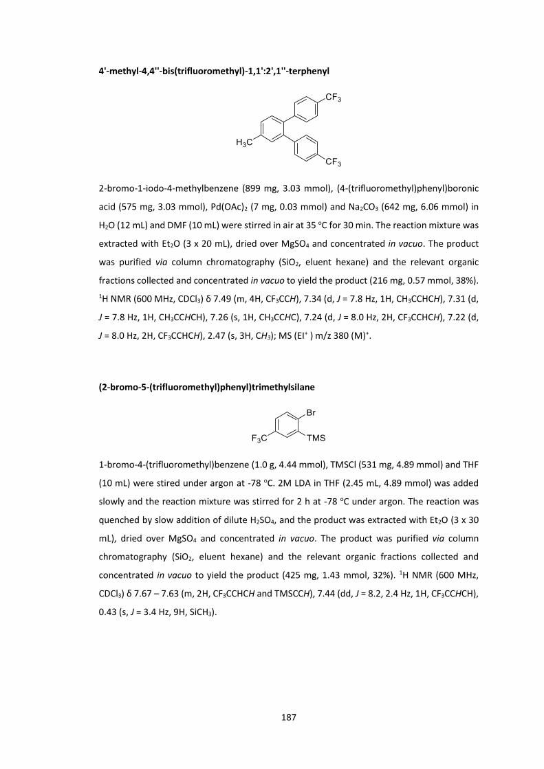
187
4'-methyl-4,4''-bis(trifluoromethyl)-1,1':2',1''-terphenyl
2-bromo-1-iodo-4-methylbenzene (899 mg, 3.03 mmol), (4-(trifluoromethyl)phenyl)boronic
acid (575 mg, 3.03 mmol), Pd(OAc)2 (7 mg, 0.03 mmol) and Na2CO3 (642 mg, 6.06 mmol) in
H2O (12 mL) and DMF (10 mL) were stirred in air at 35 oC for 30 min. The reaction mixture was
extracted with Et2O (3 x 20 mL), dried over MgSO4 and concentrated in vacuo. The product
was purified via column chromatography (SiO2, eluent hexane) and the relevant organic
fractions collected and concentrated in vacuo to yield the product (216 mg, 0.57 mmol, 38%). 1H NMR (600 MHz, CDCl3) δ 7.49 (m, 4H, CF3CCH), 7.34 (d, J = 7.8 Hz, 1H, CH3CCHCH), 7.31 (d,
J = 7.8 Hz, 1H, CH3CCHCH), 7.26 (s, 1H, CH3CCHC), 7.24 (d, J = 8.0 Hz, 2H, CF3CCHCH), 7.22 (d,
J = 8.0 Hz, 2H, CF3CCHCH), 2.47 (s, 3H, CH3); MS (EI+ ) m/z 380 (M)+.
(2-bromo-5-(trifluoromethyl)phenyl)trimethylsilane
1-bromo-4-(trifluoromethyl)benzene (1.0 g, 4.44 mmol), TMSCl (531 mg, 4.89 mmol) and THF
(10 mL) were stired under argon at -78 oC. 2M LDA in THF (2.45 mL, 4.89 mmol) was added
slowly and the reaction mixture was stirred for 2 h at -78 oC under argon. The reaction was
quenched by slow addition of dilute H2SO4, and the product was extracted with Et2O (3 x 30
mL), dried over MgSO4 and concentrated in vacuo. The product was purified via column
chromatography (SiO2, eluent hexane) and the relevant organic fractions collected and
concentrated in vacuo to yield the product (425 mg, 1.43 mmol, 32%). 1H NMR (600 MHz,
CDCl3) δ 7.67 – 7.63 (m, 2H, CF3CCHCH and TMSCCH), 7.44 (dd, J = 8.2, 2.4 Hz, 1H, CF3CCHCH),
0.43 (s, J = 3.4 Hz, 9H, SiCH3).
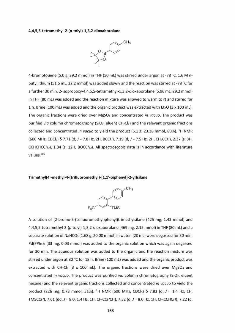
188
4,4,5,5-tetramethyl-2-(p-tolyl)-1,3,2-dioxaborolane
4-bromotouene (5.0 g, 29.2 mmol) in THF (50 mL) was stirred under argon at -78 oC. 1.6 M n-
butyllithium (51.5 mL, 32.2 mmol) was added slowly and the reaction was stirred at -78 oC for
a further 30 min. 2-isopropoxy-4,4,5,5-tetramethyl-1,3,2-dioxaborolane (5.96 mL, 29.2 mmol)
in THF (80 mL) was added and the reaction mixture was allowed to warm to rt and stirred for
1 h. Brine (100 mL) was added and the organic product was extracted with Et2O (3 x 100 mL).
The organic fractions were dried over MgSO4 and concentrated in vacuo. The product was
purified via column chromatography (SiO2, eluent CH2Cl2) and the relevant organic fractions
collected and concentrated in vacuo to yield the product (5.1 g, 23.38 mmol, 80%). 1H NMR
(600 MHz, CDCl3) δ 7.71 (d, J = 7.8 Hz, 2H, BCCH), 7.19 (d, J = 7.5 Hz, 2H, CH3CCH), 2.37 (s, 3H,
CCHCHCCH3), 1.34 (s, 12H, BOCCH3). All spectroscopic data is in accordance with literature
values.205
Trimethyl(4'-methyl-4-(trifluoromethyl)-[1,1'-biphenyl]-2-yl)silane
A solution of (2-bromo-5-(trifluoromethyl)phenyl)trimethylsilane (425 mg, 1.43 mmol) and
4,4,5,5-tetramethyl-2-(p-tolyl)-1,3,2-dioxaborolane (469 mg, 2.15 mmol) in THF (80 mL) and a
separate solution of NaHCO3 (1.68 g, 20.00 mmol) in water (20 mL) were degassed for 30 min.
Pd(PPh3)4 (33 mg, 0.03 mmol) was added to the organic solution which was again degassed
for 30 min. The aqueous solution was added to the organic and the reaction mixture was
stirred under argon at 80 oC for 18 h. Brine (100 mL) was added and the organic product was
extracted with CH2Cl2 (3 x 100 mL). The organic fractions were dried over MgSO4 and
concentrated in vacuo. The product was purified via column chromatography (SiO2, eluent
hexane) and the relevant organic fractions collected and concentrated in vacuo to yield the
product (226 mg, 0.73 mmol, 51%). 1H NMR (600 MHz, CDCl3) δ 7.83 (d, J = 1.4 Hz, 1H,
TMSCCH), 7.61 (dd, J = 8.0, 1.4 Hz, 1H, CF3CCHCH), 7.32 (d, J = 8.0 Hz, 1H, CF3CCHCH), 7.22 (d,

189
J = 7.8 Hz, 2H, CH3CCHCH), 7.16 (d, J = 7.8 Hz, 2H, CH3CCH), 2.43 (s, 3H, CH3CCHCH), 0.04 (s,
9H, SiCH3).
3-methyl-4'-(trifluoromethyl)-1,1'-biphenyl
A solution of 1-bromo-3-methylbenzene (500 mg, 2.92 mmol) and 4,4,5,5-tetramethyl-2-(p-
tolyl)-1,3,2-dioxaborolane (955 mg, 4.38 mmol) in THF (160 mL) and a separate solution of
NaHCO3 (3.36 g, 40.00 mmol) in water (40 mL) were degassed for 30 min. Pd(PPh3)4 (68 mg,
0.06 mmol) was added to the organic solution which was again degassed for 30 min. The
aqueous solution was added to the organic and the reaction mixture was stirred under argon
at 80 oC for 18 h. Brine (200 mL) was added and the organic product was extracted with CH2Cl2
(3 x 200 mL). The organic fractions were dried over MgSO4 and concentrated in vacuo to yield
the product (452 mg, 2.48 mmol, 85%). 1H NMR (600 MHz, CDCl3) δ 7.49 (d, J = 7.9 Hz, 2H,
CH3CCHCHC), 7.41 – 7.37 (m, 2H, CH3CCHCHCH and CH3CCHC), 7.32 (dd, J = 7.5, 7.5 Hz, 1H,
CH3CCHCHCH), 7.25 (d, J = 7.9 Hz, 2H, CH3CCHCHC), 7.15 (d, J = 7.5 Hz, 1H, CH3CCHCHCH), 2.42
(s, 3H, CH3), 2.40 (s, 3H, CH3). All spectroscopic data is in accordance with literature values.206
4-bromo-3,4'-dimethyl-1,1'-biphenyl
3-methyl-4'-(trifluoromethyl)-1,1'-biphenyl (100 mg, 0.55 mmol), I2 (3 mg, 0.01 mmol) and
CH2Cl2 (5 mL) were stirred at 0 oC under argon for 30 min. Br2 (0.034 mL, 0.66 mmol) in CH2Cl2
(0.66 mL) was added and the reaction mixture was stirred at 0 oC under argon in the dark for
3 h. The reaction mixture was quenched with saturated Na2SO3 solution (50 mL) and the
product was extracted with CH2Cl2 (3 x 50 mL), dried over MgSO4 and concentrated in vacuo.
The product was purified via column chromatography (SiO2, eluent hexane) and the relevant
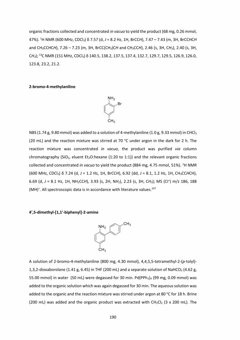
190
organic fractions collected and concentrated in vacuo to yield the product (68 mg, 0.26 mmol,
47%). 1H NMR (600 MHz, CDCl3) δ 7.57 (d, J = 8.2 Hz, 1H, BrCCH), 7.47 – 7.43 (m, 3H, BrCCHCH
and CH3CCHCH), 7.26 – 7.23 (m, 3H, BrCC(CH3)CH and CH3CCH), 2.46 (s, 3H, CH3), 2.40 (s, 3H,
CH3); 13C NMR (151 MHz, CDCl3) δ 140.5, 138.2, 137.5, 137.4, 132.7, 129.7, 129.5, 126.9, 126.0,
123.8, 23.2, 21.2.
2-bromo-4-methylaniline
NBS (1.74 g, 9.80 mmol) was added to a solution of 4-methylaniline (1.0 g, 9.33 mmol) in CHCl3
(20 mL) and the reaction mixture was stirred at 70 oC under argon in the dark for 2 h. The
reaction mixture was concentrated in vacuo, the product was purified via column
chromatography (SiO2, eluent Et2O:hexane (1:20 to 1:1)) and the relevant organic fractions
collected and concentrated in vacuo to yield the product (884 mg, 4.75 mmol, 51%). 1H NMR
(600 MHz, CDCl3) δ 7.24 (d, J = 1.2 Hz, 1H, BrCCH), 6.92 (dd, J = 8.1, 1.2 Hz, 1H, CH3CCHCH),
6.69 (d, J = 8.1 Hz, 1H, NH2CCH), 3.93 (s, 2H, NH2), 2.23 (s, 3H, CH3); MS (CI+) m/z 186, 188
(MH)+. All spectroscopic data is in accordance with literature values.207
4',5-dimethyl-[1,1'-biphenyl]-2-amine
A solution of 2-bromo-4-methylaniline (800 mg, 4.30 mmol), 4,4,5,5-tetramethyl-2-(p-tolyl)-
1,3,2-dioxaborolane (1.41 g, 6.45) in THF (200 mL) and a separate solution of NaHCO3 (4.62 g,
55.00 mmol) in water (50 mL) were degassed for 30 min. Pd(PPh3)4 (99 mg, 0.09 mmol) was
added to the organic solution which was again degassed for 30 min. The aqueous solution was
added to the organic and the reaction mixture was stirred under argon at 80 oC for 18 h. Brine
(200 mL) was added and the organic product was extracted with CH2Cl2 (3 x 200 mL). The
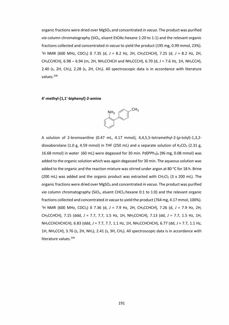
191
organic fractions were dried over MgSO4 and concentrated in vacuo. The product was purified
via column chromatography (SiO2, eluent EtOAc:hexane 1:20 to 1:1) and the relevant organic
fractions collected and concentrated in vacuo to yield the product (195 mg, 0.99 mmol, 23%). 1H NMR (600 MHz, CDCl3) δ 7.35 (d, J = 8.2 Hz, 2H, CH3CCHCH), 7.25 (d, J = 8.2 Hz, 2H,
CH3CCHCH), 6.98 – 6.94 (m, 2H, NH2CCHCH and NH2CCCH), 6.70 (d, J = 7.6 Hz, 1H, NH2CCH),
2.40 (s, 2H, CH3), 2.28 (s, 2H, CH3). All spectroscopic data is in accordance with literature
values.208
4'-methyl-[1,1'-biphenyl]-2-amine
A solution of 2-bromoaniline (0.47 mL, 4.17 mmol), 4,4,5,5-tetramethyl-2-(p-tolyl)-1,3,2-
dioxaborolane (1.0 g, 4.59 mmol) in THF (250 mL) and a separate solution of K2CO3 (2.31 g,
16.68 mmol) in water (60 mL) were degassed for 30 min. Pd(PPh3)4 (96 mg, 0.08 mmol) was
added to the organic solution which was again degassed for 30 min. The aqueous solution was
added to the organic and the reaction mixture was stirred under argon at 80 oC for 18 h. Brine
(200 mL) was added and the organic product was extracted with CH2Cl2 (3 x 200 mL). The
organic fractions were dried over MgSO4 and concentrated in vacuo. The product was purified
via column chromatography (SiO2, eluent CHCl3:hexane 0:1 to 1:0) and the relevant organic
fractions collected and concentrated in vacuo to yield the product (764 mg, 4.17 mmol, 100%). 1H NMR (600 MHz, CDCl3) δ 7.36 (d, J = 7.9 Hz, 2H, CH3CCHCH), 7.26 (d, J = 7.9 Hz, 2H,
CH3CCHCH), 7.15 (ddd, J = 7.7, 7.7, 1.5 Hz, 1H, NH2CCHCH), 7.13 (dd, J = 7.7, 1.5 Hz, 1H,
NH2CCHCHCHCH), 6.83 (ddd, J = 7.7, 7.7, 1.1 Hz, 1H, NH2CCHCHCH), 6.77 (dd, J = 7.7, 1.1 Hz,
1H, NH2CCH), 3.76 (s, 2H, NH2), 2.41 (s, 3H, CH3). All spectroscopic data is in accordance with
literature values.209
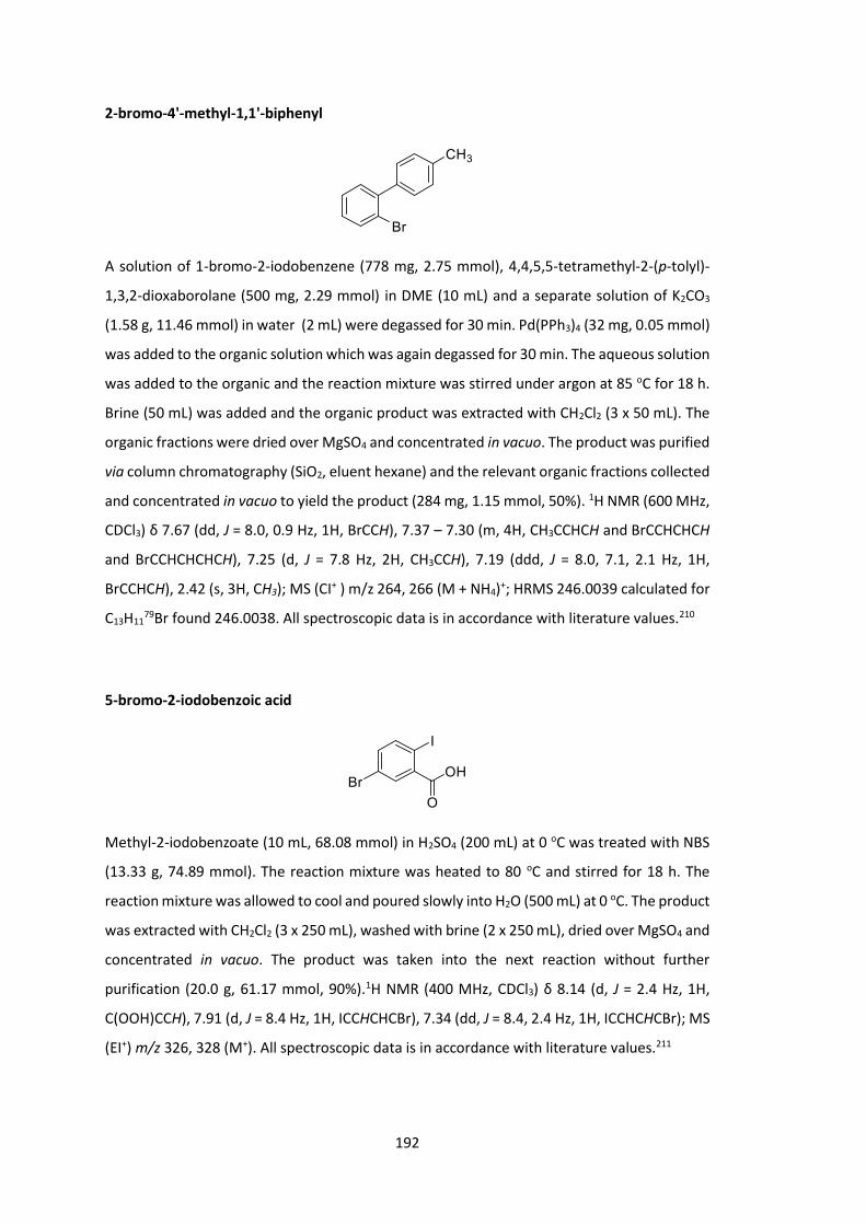
192
2-bromo-4'-methyl-1,1'-biphenyl
A solution of 1-bromo-2-iodobenzene (778 mg, 2.75 mmol), 4,4,5,5-tetramethyl-2-(p-tolyl)-
1,3,2-dioxaborolane (500 mg, 2.29 mmol) in DME (10 mL) and a separate solution of K2CO3
(1.58 g, 11.46 mmol) in water (2 mL) were degassed for 30 min. Pd(PPh3)4 (32 mg, 0.05 mmol)
was added to the organic solution which was again degassed for 30 min. The aqueous solution
was added to the organic and the reaction mixture was stirred under argon at 85 oC for 18 h.
Brine (50 mL) was added and the organic product was extracted with CH2Cl2 (3 x 50 mL). The
organic fractions were dried over MgSO4 and concentrated in vacuo. The product was purified
via column chromatography (SiO2, eluent hexane) and the relevant organic fractions collected
and concentrated in vacuo to yield the product (284 mg, 1.15 mmol, 50%). 1H NMR (600 MHz,
CDCl3) δ 7.67 (dd, J = 8.0, 0.9 Hz, 1H, BrCCH), 7.37 – 7.30 (m, 4H, CH3CCHCH and BrCCHCHCH
and BrCCHCHCHCH), 7.25 (d, J = 7.8 Hz, 2H, CH3CCH), 7.19 (ddd, J = 8.0, 7.1, 2.1 Hz, 1H,
BrCCHCH), 2.42 (s, 3H, CH3); MS (CI+ ) m/z 264, 266 (M + NH4)+; HRMS 246.0039 calculated for
C13H1179Br found 246.0038. All spectroscopic data is in accordance with literature values.210
5-bromo-2-iodobenzoic acid
Methyl-2-iodobenzoate (10 mL, 68.08 mmol) in H2SO4 (200 mL) at 0 oC was treated with NBS
(13.33 g, 74.89 mmol). The reaction mixture was heated to 80 oC and stirred for 18 h. The
reaction mixture was allowed to cool and poured slowly into H2O (500 mL) at 0 oC. The product
was extracted with CH2Cl2 (3 x 250 mL), washed with brine (2 x 250 mL), dried over MgSO4 and
concentrated in vacuo. The product was taken into the next reaction without further
purification (20.0 g, 61.17 mmol, 90%).1H NMR (400 MHz, CDCl3) δ 8.14 (d, J = 2.4 Hz, 1H,
C(OOH)CCH), 7.91 (d, J = 8.4 Hz, 1H, ICCHCHCBr), 7.34 (dd, J = 8.4, 2.4 Hz, 1H, ICCHCHCBr); MS
(EI+) m/z 326, 328 (M+). All spectroscopic data is in accordance with literature values.211
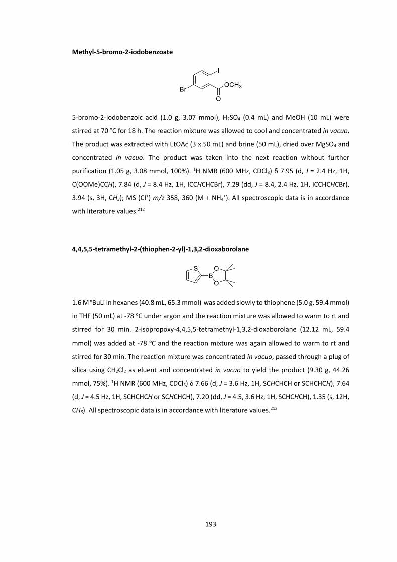
193
Methyl-5-bromo-2-iodobenzoate
5-bromo-2-iodobenzoic acid (1.0 g, 3.07 mmol), H2SO4 (0.4 mL) and MeOH (10 mL) were
stirred at 70 oC for 18 h. The reaction mixture was allowed to cool and concentrated in vacuo.
The product was extracted with EtOAc (3 x 50 mL) and brine (50 mL), dried over MgSO4 and
concentrated in vacuo. The product was taken into the next reaction without further
purification (1.05 g, 3.08 mmol, 100%). 1H NMR (600 MHz, CDCl3) δ 7.95 (d, J = 2.4 Hz, 1H,
C(OOMe)CCH), 7.84 (d, J = 8.4 Hz, 1H, ICCHCHCBr), 7.29 (dd, J = 8.4, 2.4 Hz, 1H, ICCHCHCBr),
3.94 (s, 3H, CH3); MS (CI+) m/z 358, 360 (M + NH4+). All spectroscopic data is in accordance
with literature values.212
4,4,5,5-tetramethyl-2-(thiophen-2-yl)-1,3,2-dioxaborolane
1.6 M nBuLi in hexanes (40.8 mL, 65.3 mmol) was added slowly to thiophene (5.0 g, 59.4 mmol)
in THF (50 mL) at -78 oC under argon and the reaction mixture was allowed to warm to rt and
stirred for 30 min. 2-isopropoxy-4,4,5,5-tetramethyl-1,3,2-dioxaborolane (12.12 mL, 59.4
mmol) was added at -78 oC and the reaction mixture was again allowed to warm to rt and
stirred for 30 min. The reaction mixture was concentrated in vacuo, passed through a plug of
silica using CH2Cl2 as eluent and concentrated in vacuo to yield the product (9.30 g, 44.26
mmol, 75%). 1H NMR (600 MHz, CDCl3) δ 7.66 (d, J = 3.6 Hz, 1H, SCHCHCH or SCHCHCH), 7.64
(d, J = 4.5 Hz, 1H, SCHCHCH or SCHCHCH), 7.20 (dd, J = 4.5, 3.6 Hz, 1H, SCHCHCH), 1.35 (s, 12H,
CH3). All spectroscopic data is in accordance with literature values.213

194
Methyl 5-bromo-2-(thiophen-2-yl)benzoate
Methyl-5-bromo-2-iodobenzoate (514 mg, 1.51 mmol), 4,4,5,5-tetramethyl-2-(thiophen-2-
yl)-1,3,2-dioxaborolane (265 mg, 1.26 mmol) and THF (10 mL) were degassed with argon for
30 mins. Pd(PPh3)4 (29 mg, 0.03 mmol) was added and the reaction mixture was further
degassed for 30 mins. Degassed K2CO3 (871 mg, 6.30 mmol) in H2O (2 mL) was added and the
reaction mixture was heated to 80 oC for 64 h. The reaction mixture was allowed to cool,
concentrated in vacuo, dissolved in CH2Cl2 (50 mL), washed with brine (3 x 50 mL), dried over
MgSO4 and concentrated in vacuo. The product was purified via column chromatography
(SiO2, Eluent 5 to 50% CH2Cl2 in Hexane) and the organic fractions collected and concentrated
in vacuo to yield the product (309 mg, 1.04 mmol, 69%). 1H NMR (400 MHz, CDCl3) δ 7.86 (t, J
= 2.2 Hz, 1H, C(OOMe)CCH), 7.61 (dd, J = 8.3, 2.2 Hz, 1H, BrCCHCH), 7.38 – 7.34 (m, 2H,
BrCCHCH and SCHCHCH), 7.09 – 7.00 (m, 2H, SCHCHCH and SCHCHCH), 3.75 (s, 3H, CH3); MS
(CI+) m/z 314, 316 (M + NH4+); HRMS 313.9845 calculated for C12H9O2SBr79 + NH4 found
313.9846.
5-bromo-2-(thiophen-2-yl)benzoic acid
Methyl-5-bromo-2-(thiophen-2-yl)benzoate (3.22 g, 10.8 mmol), NaOH (1.30 g, 32.4 mmol)
and EtOH (150 mL) were stirred at 85 oC for 3 h. The reaction mixture was concentrated in
vacuo and the product was extracted with CH2Cl2 (3 x 200 mL) and 2M HCl solution (200 mL),
dried over MgSO4 and concentrated in vacuo. The product was taken into the next reaction
without further purification (2.60 g, 9.18 mmol, 85%). 1H NMR (600 MHz, CDCl3) δ 8.03 (s, 1H,
COOHCCH), 7.67 (d, J = 8.3 Hz, 1H, BrCCHCH), 7.39 (dd, J = 4.9, 1.4 Hz, 1H, SCH), 7.37 (d, J =
8.3 Hz, 1H, BrCCHCH), 7.11 – 7.05 (m, 2H, SCHCH and SCHCHCH); MS (CI+) m/z 300, 302 (M +
NH4+); HRMS 299.9688 calculated for C11H7O2S79Br + NH4 found 299.9689.
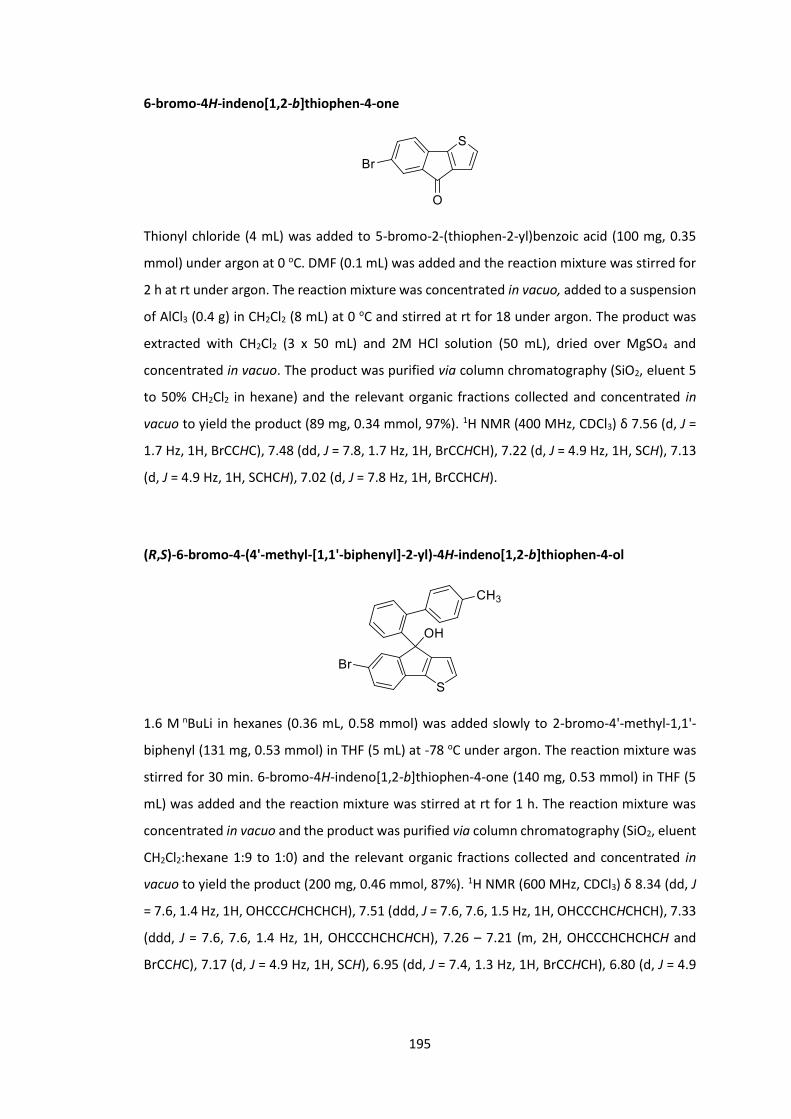
195
6-bromo-4H-indeno[1,2-b]thiophen-4-one
Thionyl chloride (4 mL) was added to 5-bromo-2-(thiophen-2-yl)benzoic acid (100 mg, 0.35
mmol) under argon at 0 oC. DMF (0.1 mL) was added and the reaction mixture was stirred for
2 h at rt under argon. The reaction mixture was concentrated in vacuo, added to a suspension
of AlCl3 (0.4 g) in CH2Cl2 (8 mL) at 0 oC and stirred at rt for 18 under argon. The product was
extracted with CH2Cl2 (3 x 50 mL) and 2M HCl solution (50 mL), dried over MgSO4 and
concentrated in vacuo. The product was purified via column chromatography (SiO2, eluent 5
to 50% CH2Cl2 in hexane) and the relevant organic fractions collected and concentrated in
vacuo to yield the product (89 mg, 0.34 mmol, 97%). 1H NMR (400 MHz, CDCl3) δ 7.56 (d, J =
1.7 Hz, 1H, BrCCHC), 7.48 (dd, J = 7.8, 1.7 Hz, 1H, BrCCHCH), 7.22 (d, J = 4.9 Hz, 1H, SCH), 7.13
(d, J = 4.9 Hz, 1H, SCHCH), 7.02 (d, J = 7.8 Hz, 1H, BrCCHCH).
(R,S)-6-bromo-4-(4'-methyl-[1,1'-biphenyl]-2-yl)-4H-indeno[1,2-b]thiophen-4-ol
1.6 M nBuLi in hexanes (0.36 mL, 0.58 mmol) was added slowly to 2-bromo-4'-methyl-1,1'-
biphenyl (131 mg, 0.53 mmol) in THF (5 mL) at -78 oC under argon. The reaction mixture was
stirred for 30 min. 6-bromo-4H-indeno[1,2-b]thiophen-4-one (140 mg, 0.53 mmol) in THF (5
mL) was added and the reaction mixture was stirred at rt for 1 h. The reaction mixture was
concentrated in vacuo and the product was purified via column chromatography (SiO2, eluent
CH2Cl2:hexane 1:9 to 1:0) and the relevant organic fractions collected and concentrated in
vacuo to yield the product (200 mg, 0.46 mmol, 87%). 1H NMR (600 MHz, CDCl3) δ 8.34 (dd, J
= 7.6, 1.4 Hz, 1H, OHCCCHCHCHCH), 7.51 (ddd, J = 7.6, 7.6, 1.5 Hz, 1H, OHCCCHCHCHCH), 7.33
(ddd, J = 7.6, 7.6, 1.4 Hz, 1H, OHCCCHCHCHCH), 7.26 – 7.21 (m, 2H, OHCCCHCHCHCH and
BrCCHC), 7.17 (d, J = 4.9 Hz, 1H, SCH), 6.95 (dd, J = 7.4, 1.3 Hz, 1H, BrCCHCH), 6.80 (d, J = 4.9

196
Hz, 1H, SCHCH), 6.70 (d, J = 7.4 Hz, 1H, BrCCHCH), 6.59 (br d, J = 31.0 Hz, 2H, CH3CCHCH), 6.11
(d, J = 8.1 Hz, 2H, CH3CCH), 2.27 (s, 1H, OH), 2.19 (s, 3H, CH3); MS (CI+) m/z 432, 434 (M+).
(R,S)-6'-bromo-2-methylspiro[fluorene-9,4'-indeno[1,2-b]thiophene]
Concentrated HCl solution (5 drops) was added to (R,S)-6-bromo-4-(4'-methyl-[1,1'-biphenyl]-
2-yl)-4H-indeno[1,2-b]thiophen-4-ol (200 mg, 0.46 mmol) in AcOH (50 mL) and the reaction
mixture was stirred at rt for 10 mins. The reaction mixture was poured into H2O (500 mL) and
the precipitate was filtered and washed with H2O (500 mL). The product was purified via
column chromatography (SiO2, eluent CH2Cl2:hexane 1:9 to 1:1) and the relevant organic
fractions collected and concentrated in vacuo to yield the product (130 mg, 0.31 mmol, 67%). 1H NMR (600 MHz, CDCl3) δ 7.78 (d, J = 7.6 Hz, 1H, CHCHCHCHCCCH), 7.71 (d, J = 7.8 Hz, 1H,
CH3CCHCH), 7.42 – 7.39 (m, 2H, BrCCHCH and CH3CCHCH), 7.37 (ddd, J = 7.6, 7.4, 1.0 Hz, 1H,
CHCHCHCHCCCH), 7.26 (d, J = 4.9 Hz, 1H, SCH), 7.19 (d, J = 6.9 Hz, 1H, BrCCHCH), 7.11 (ddd, J
= 7.4, 7.4, 1.0 Hz, 1H, CHCHCHCHCCCH), 6.77 (d, J = 7.4 Hz, 1H, CHCHCHCHCCCH), 6.75 (d, J =
1.7 Hz, 1H, CH3CCHC), 6.59 (s, 1H, BrCCHC), 6.47 (d, J = 4.9 Hz, 1H, SCHCH), 2.25 (s, 3H, CH3).
(R,S)- 2',6'-dibromo-2-(bromomethyl)spiro[fluorene-9,4'-indeno[1,2-b]thiophene]
(R,S)-6'-bromo-2-methylspiro[fluorene-9,4'-indeno[1,2-b]thiophene] (130 mg, 0.31 mmol),
NBS (61 mg, 0.34 mmol), 25% benzoyl peroxide solution in H2O (12 mg, 0.04 mmol) and CHCl3
(5 mL) were stirred at 85 oC under argon for 18 h. The reaction mixture was concentrated in
vacuo and the product was purified via column chromatography (SiO2, eluent CH2Cl2:hexane
1:9 to 1:1) and the relevant organic fractions collected and concentrated in vacuo to yield the
product (80 mg, 0.16 mmol, 52%). 1H NMR (400 MHz, CDCl3) δ 7.82 – 7.77 (m, 2H,
CHCHCHCHCCCH and CH2CCHCH), 7.49 – 7.37 (m, 3H, CHCHCHCHCCCH and CH2CCHCH and

197
BrCCHCH), 7.34 (d, J = 8.1 Hz, 1H, BrCCHCH), 7.17 (ddd, J = 7.4, 7.4, 1.0 Hz, 1H,
CHCHCHCHCCCH), 6.81 – 6.77 (m, 2H, CHCHCHCHCCCH and BrCCHC), 6.74 (d, J = 1.7 Hz, 1H,
CH2CCHC), 6.49 (s, 1H, SCCH), 4.41 (d, J = 1.6 Hz, 2H, CH2).
(R,S)- 2',6'-dibromospiro[fluorene-9,4'-indeno[1,2-b]thiophene]-2-carbaldehyde
(R,S)- 2',6'-dibromo-2-(bromomethyl)spiro[fluorene-9,4'-indeno[1,2-b]thiophene] (80 mg,
0.14 mmol), NaHCO3 (1.0 g) and DMSO (5 mL) were stirred at 110 oC under argon for 18 h. The
reaction mixture was poured into H2O (50 mL) and the product was extracted with CH2Cl2 (3 x
50 mL) and concentrated in vacuo. The product was taken into the next reaction without
further purification (69 mg, 0.14 mmol, 100%). 1H NMR (600 MHz, CDCl3) δ 9.89 (s, 1H, CHO),
7.97 (d, J = 7.8 Hz, 1H, OCHCCHCH), 7.93 (d, J = 7.8 Hz, 1H, OCHCCHCH), 7.90 (d, J = 7.8 Hz, 1H,
CHCHCHCHCCCH), 7.48 – 7.42 (m, 3H, BrCCHCH and CHCHCHCHCCCH and CHCHCHCHCCCH),
7.36 (d, J = 8.2 Hz, 1H, BrCCHCH), 7.33 (s, 1H, OCHCCHC), 6.87 (d, J = 7.5 Hz, 1H,
CHCHCHCHCCCH), 6.71 (s, 1H, BrCCHC), 6.47 (s, 1H, SCCH).
(R,S)- 2',6'-dibromospiro[fluorene-9,4'-indeno[1,2-b]thiophene]-2-carbonitrile
28% ammonium hydroxide solution (1.0 mL) and I2 (89 mg, 0.35 mmol) were added to a
solution of (R,S)- 2',6'-dibromospiro[fluorene-9,4'-indeno[1,2-b]thiophene]-2-carbaldehyde
(69 mg, 0.16 mmol) in acetonitrile (4 mL) and THF (1 mL). The reaction mixture was allowed
to stir for 18 h. The reaction was quenched with saturated Na2SO3 solution (50 mL) and the
product was extracted with Et2O (2 x 50mL), dried over MgSO4 and concentrated in vacuo to
give an off white powder (8 mg, 0.02 mmol, 10%). 1H NMR (400 MHz, CDCl3) δ 7.92 – 7.85 (m,
2H, NCCCHCH and CHCHCHCHCCCH), 7.70 (dd, J = 7.9, 1.5 Hz, 1H, NCCCHCH), 7.49 – 7.42 (m,
2H, BrCCHCH and CHCHCHCHCCCH), 7.36 (d, J = 8.0 Hz, 1H, BrCCHCH), 7.27 (ddd, J = 7.6, 7.6,

198
1.1 Hz, 2H, CHCHCHCHCCCH), 7.08 (d, J = 1.5 Hz, 1H, NCCCHC), 6.86 (d, J = 7.6 Hz, 1H,
CHCHCHCHCCCH), 6.70 (d, J = 1.6 Hz, 1H, BrCCHC), 6.46 (s, 1H, SCCH).

199

200
References
1. Hiorns, R. C.; Boucher, R. J.; Duhlev, R.; Hellwich, K.-H.; Hodge, P.; Jenkins, A. D.; Jones, R. G.; Kahovec, J.; Moad, G.; Ober, C. K.; Smith, D. W.; Stepto, R. F. T.; Vairon, J.-P.; Vohlídal, J., Polym Int, 2013, 62 (1), I-II. 2. Kafafi, Z., Organic electroluminescence. CRC Press: Boca Raton, 2005. 3. Shirakawa, H.; Louis, E. J.; MacDiarmid, A. G.; Chiang, C. K.; Heeger, A. J., J Chem Soc Chem Commun, 1977, (16), 578-580. 4. Burroughes, J. H.; Bradley, D. D. C.; Brown, A. R.; Marks, R. N.; Mackay, K.; Friend, R. H.; Burns, P. L.; Holmes, A. B., Nature, 1990, 347, 539. 5. Thejo Kalyani, N.; Dhoble, S. J., Renew Sust Energ Rev, 2012, 16 (5), 2696-2723. 6. Geffroy, B.; le Roy, P.; Prat, C., Polym Int, 2006, 55 (6), 572-582. 7. Ahmad, J.; Bazaka, K.; Anderson, L. J.; White, R. D.; Jacob, M. V., Renew Sust Energ Rev, 2013, 27, 104-117. 8. Klauk, H., Chem Soc Rev, 2010, 39 (7), 2643-2666. 9. Alexander J. C. Kuehne, M. C. G., Chem Rev, 2016, 116 (21), 12823–12864. 10. Borek, C.; Hanson, K.; Djurovich, P. I.; Thompson, M. E.; Aznavour, K.; Bau, R.; Sun, Y.; Forrest, S. R.; Brooks, J.; Michalski, L.; Brown, J., Angew Chem Int Edit, 2007, 46 (7), 1109-1112. 11. Stephen C. Moratti, D. D. C. B., Raoul Cervini, Richard H. Friend, Neil C. Greenham, Andrew B. Holmes, Proc Spie, 1994, 2144, 108-114. 12. Hung, L. S.; Chen, C. H., Mat Sci Eng R, 2002, 39 (5), 143-222. 13. van Dijken, A.; Perro, A.; Meulenkamp, E. A.; Brunner, K., Org Electron, 2003, 4 (2), 131-141. 14. Saxena, K.; Jain, V. K.; Mehta, D. S., Optical Materials, 2009, 32 (1), 221-233. 15. Halls, J. J. M.; Walsh, C. A.; Greenham, N. C.; Marseglia, E. A.; Friend, R. H.; Moratti, S. C.; Holmes, A. B., Nature, 1995, 376, 498. 16. Lu, L.; Yu, L., Adv Mater, 2014, Advance article DOI:10.1002/adma.201400384. 17. Xinpeng Jiang, X. G., Jiang Peng, Dahui Zhao, Yuguo Ma, ACS Appl Mater Interfaces, 2016, 8 (18), 11441-11449. 18. Tomas Serevičius, R. K., Povilas Adomėnas, Ona Adomėnienė, Gediminas Kreiza, Vygintas Jankauskas, Karolis Kazlauskas, Arunas Miasojedovas, Vygintas Jankus, Andy Monkman, and Saulius Juršėnas, J Phys Chem, 2017, 121 (15), 8515-8524. 19. Zhao, J.; Ji, S.; Guo, H., RSC Adv, 2011, 1 (6), 937-950. 20. Peet, J. K., J. Y.; Coates, N. E.; Ma, W. L.; Moses, D.; Heeger, A. J.; Bazan, G. C., Nat Mater, 2007, 6 (7), 497-500. 21. Shockley, W.; Queisser, H. J., J Appl Phys, 1961, 32 (3), 510-519. 22. Baldo, M. A.; Adachi, C.; Forrest, S. R., Phys Rev B, 2000, 62 (16), 10967-10977. 23. Ford, T. A.; Avilov, I.; Beljonne, D.; Greenham, N. C., Phys Rev B, 2005, 71 (12), 125212. 24. Umeyama, T.; Imahori, H., J Mater Chem A, 2014, Advance article DOI:10.1039/C3TA15387H. 25. Wasielewski, M. R., Chem Rev, 1992, 92 (3), 435-461. 26. Yella, A.; Lee, H.-W.; Tsao, H. N.; Yi, C.; Chandiran, A. K.; Nazeeruddin, M. K.; Diau, E. W.-G.; Yeh, C.-Y.; Zakeeruddin, S. M.; Grätzel, M., Science, 2011, 334 (6056), 629-634. 27. Zhao, Q.; Huang, C.; Li, F., Chem Soc Rev, 2011, 40 (5), 2508-2524. 28. Ethirajan, M.; Chen, Y.; Joshi, P.; Pandey, R. K., Chem Soc Rev, 2011, 40 (1), 340-362. 29. Imahori, H.; Yamada, H.; Guldi, D. M.; Endo, Y.; Shimomura, A.; Kundu, S.; Yamada, K.; Okada, T.; Sakata, Y.; Fukuzumi, S., Angew Chem Int Edit, 2002, 41 (13), 2344-2347.

201
30. Ryan, A.; Tuffy, B.; Horn, S.; Blau, W. J.; Senge, M. O., Tetrahedron, 2011, 67 (43), 8248-8254. 31. Huang, X.; Zhu, C.; Zhang, S.; Li, W.; Guo, Y.; Zhan, X.; Liu, Y.; Bo, Z., Macromolecules, 2008, 41 (19), 6895-6902. 32. Umeyama, T.; Takamatsu, T.; Tezuka, N.; Matano, Y.; Araki, Y.; Wada, T.; Yoshikawa, O.; Sagawa, T.; Yoshikawa, S.; Imahori, H., J Phys Chem C, 2009, 113 (24), 10798-10806. 33. Lindsey, J. S.; Hsu, H. C.; Schreiman, I. C., Tetrahedron Lett, 1986, 27 (41), 4969-4970. 34. Lindsey, J. S.; Schreiman, I. C.; Hsu, H. C.; Kearney, P. C.; Marguerettaz, A. M., J Org Chem, 1987, 52 (5), 827-836. 35. Lindsey, J. S.; Wagner, R. W., J Org Chem, 1989, 54 (4), 828-836. 36. Cammidge, A. N.; Öztürk, O., Tetrahedron Lett, 2001, 42 (2), 355-358. 37. Filatov, M. A.; Lebedev, A. Y.; Vinogradov, S. A.; Cheprakov, A. V., J Org Chem, 2008, 73 (11), 4175-4185. 38. Littler, B. J.; Ciringh, Y.; Lindsey, J. S., J Org Chem, 1999, 64 (8), 2864-2872. 39. Spellane, P. J.; Gouterman, M.; Antipas, A.; Kim, S.; Liu, Y. C., Inorg Chem, 1980, 19 (2), 386-391. 40. Minaev, B.; Baryshnikov, G.; Agren, H., Phys Chem Chem Phys, 2014, 16 (5), 1719-1758. 41. Baldo, M. A.; O'Brien, D. F.; You, Y.; Shoustikov, A.; Sibley, S.; Thompson, M. E.; Forrest, S. R., Nature, 1998, 395 (6698), 151-154. 42. Sudhakar, M.; Djurovich, P. I.; Hogen-Esch, T. E.; Thompson, M. E., J Am Chem Soc, 2003, 125 (26), 7796-7797. 43. Lane, P. A.; Palilis, L. C.; O’Brien, D. F.; Giebeler, C.; Cadby, A. J.; Lidzey, D. G.; Campbell, A. J.; Blau, W.; Bradley, D. D. C., Phys Rev B, 2001, 63 (23), 235206. 44. Chen, X.; Liao, J.-L.; Liang, Y.; Ahmed, M. O.; Tseng, H.-E.; Chen, S.-A., J Am Chem Soc, 2003, 125 (3), 636-637. 45. Sandee, A. J.; Williams, C. K.; Evans, N. R.; Davies, J. E.; Boothby, C. E.; Köhler, A.; Friend, R. H.; Holmes, A. B., J Am Chem Soc, 2004, 126 (22), 7041-7048. 46. Morgado, J.; Cacialli, F.; Friend, R. H.; Iqbal, R.; Yahioglu, G.; Milgrom, L. R.; Moratti, S. C.; Holmes, A. B., Chem Phys Lett, 2000, 325 (5–6), 552-558. 47. Iqbal, R.; Moratti, S. C.; Holmes, A. B.; yahioglu, G.; Milgrom, L. R.; cacialli, F.; Morgado, J.; friend, R. H., J Mater Sci-Mater El, 2000, 11 (2), 97-103. 48. Morgado, J.; Cacialli, F.; Iqbal, R.; Moratti, S. C.; Holmes, A. B.; Yahioglu, G.; Milgrom, L. R.; Friend, R. H., J Mater Chem, 2001, 11 (2), 278-283. 49. Fenwick, O.; Sprafke, J. K.; Binas, J.; Kondratuk, D. V.; Di Stasio, F.; Anderson, H. L.; Cacialli, F., Nano Lett, 2011, 11 (6), 2451-2456. 50. Li, P.; Fenwick, O.; Yilmaz, S.; Breusov, D.; Caruana, D. J.; Allard, S.; Scherf, U.; Cacialli, F., Chem Commun, 2011, 47 (31), 8820-8822. 51. Steckler, T. T.; Fenwick, O.; Lockwood, T.; Andersson, M. R.; Cacialli, F., Macromol Rapid Comm, 2013, 34 (12), 990-996. 52. Steckler, T. T.; Lee, M. J.; Chen, Z.; Fenwick, O.; Andersson, M. R.; Cacialli, F.; Sirringhaus, H., J Mater Chem C, 2014, 2 (26), 5133-5141. 53. Tregnago, G.; Fléchon, C.; Choudhary, S.; Gozalvez, C.; Mateo-Alonso, A.; Cacialli, F., Appl Phys Lett, 2014, 105 (14), 143304. 54. Day, N. U.; Wamser, C. C.; Walter, M. G., Polym Int, 2015, 64 (7), 833-857. 55. Hou, Q.; Zhang, Y.; Li, F.; Peng, J.; Cao, Y., Organometallics, 2005, 24 (19), 4509-4518. 56. Zhuang, W.; Zhang, Y.; Hou, Q.; Wang, L.; Cao, Y., J Polym Sci Pol Chem, 2006, 44 (13), 4174-4186. 57. Cho, N. S.; Hwang, D.-H.; Lee, J.-I.; Jung, B.-J.; Shim, H.-K., Macromolecules, 2002, 35 (4), 1224-1228. 58. Dennler, G.; Scharber, M. C.; Brabec, C. J., Adv Mater, 2009, 21 (13), 1323-1338.
202
59. Deng, Y. Y.; Sirringhaus, H., Phys Rev B, 2005, 72 (4), 045207. 60. Kahveci, Z.; Martínez-Tomé, M. J.; Mallavia, R.; Mateo, C. R., ACS Appl Mater Interfaces, 2017, 9 (1), 136-144. 61. Freeman, D. M. E.; Tregnago, G.; Rodriguez, S. A.; Fallon, K. J.; Cacialli, F.; Bronstein, H., J Org Semiconductors, 2015, 3 (1), 1-7. 62. Freeman, D. M. E.; Minotto, A.; Duffy, W.; Fallon, K. J.; McCulloch, I.; Cacialli, F.; Bronstein, H., Polym Chem-UK, 2016, 7 (3), 722-730. 63. Yu, L.; Muthukumaran, K.; Sazanovich, I. V.; Kirmaier, C.; Hindin, E.; Diers, J. R.; Boyle, P. D.; Bocian, D. F.; Holten, D.; Lindsey, J. S., Inorg Chem, 2003, 42 (21), 6629-6647. 64. Jiang, B.; Jones, W. E., Macromolecules, 1997, 30 (19), 5575-5581. 65. Kwong, R. C.; Sibley, S.; Dubovoy, T.; Baldo, M.; Forrest, S. R.; Thompson, M. E., Chem Mater, 1999, 11 (12), 3709-3713. 66. Ponterini, G.; Serpone, N.; Bergkamp, M. A.; Netzel, T. L., J Am Chem Soc, 1983, 105 (14), 4639-4645. 67. Becker, K.; Lupton, J. M.; Feldmann, J.; Nehls, B. S.; Galbrecht, F.; Gao, D. Q.; Scherf, U., Adv Funct Mater, 2006, 16 (3), 364-370. 68. Hou, Q.; Zhang, Y.; Li, F. Y.; Peng, J. B.; Cao, Y., Organometallics, 2005, 24 (19), 4509-4518. 69. Zhuang, W. L.; Zhang, Y.; Hou, Q.; Wang, L.; Cao, Y., J Polym Sci Pol Chem, 2006, 44 (13), 4174-4186. 70. Singh-Rachford, T. N.; Castellano, F. N., Coordin Chem Rev, 2010, 254 (21–22), 2560-2573. 71. Zhao, J.; Wu, W.; Sun, J.; Guo, S., Chem Soc Rev, 2013, 42 (12), 5323-5351. 72. Monguzzi, A.; Tubino, R.; Hoseinkhani, S.; Campione, M.; Meinardi, F., Phys Chem Chem Phys, 2012, 14 (13), 4322-4332. 73. Monguzzi, A.; Tubino, R.; Meinardi, F., Phys Rev B, 2008, 77 (15), 155122. 74. Lee, S. H.; Ayer, M. A.; Vadrucci, R.; Weder, C.; Simon, Y. C., Polym Chem-UK, 2014, 5 (24), 6898-6904. 75. Dzebo, D.; Börjesson, K.; Gray, V.; Moth-Poulsen, K.; Albinsson, B., J Phys Chem C, 2016, 120 (41), 23397-23406. 76. Wilson, C. J.; Wilson, D. A.; Boyle, R. W.; Mehl, G. H., J Mater Chem C, 2013, 1 (1), 144-150. 77. Maiti, N. C.; Mazumdar, S.; Periasamy, N., J Phys Chem B, 1998, 102 (9), 1528-1538. 78. Xia, Z.-Y.; Su, J.-H.; Wong, W.-Y.; Wang, L.; Cheah, K.-W.; Tian, H.; Chen, C. H., J Mater Chem, 2010, 20 (38), 8382-8388. 79. Li, Y.; Rizzo, A.; Salerno, M.; Mazzeo, M.; Huo, C.; Wang, Y.; Li, K.; Cingolani, R.; Gigli, G., Appl Phys Lett, 2006, 89 (6), 061125. 80. Sun, Y.; Borek, C.; Hanson, K.; Djurovich, P. I.; Thompson, M. E.; Brooks, J.; Brown, J. J.; Forrest, S. R., Appl Phys Lett, 2007, 90 (21), 213503. 81. Che, C.-M.; Hou, Y.-J.; Chan, M. C. W.; Guo, J.; Liu, Y.; Wang, Y., J Mater Chem, 2003, 13 (6), 1362-1366. 82. Lai, S.-W.; Hou, Y.-J.; Che, C.-M.; Pang, H.-L.; Wong, K.-Y.; Chang, C. K.; Zhu, N., Inorg Chem, 2004, 43 (12), 3724-3732. 83. Egbe, D. A. M.; Türk, S.; Rathgeber, S.; Kühnlenz, F.; Jadhav, R.; Wild, A.; Birckner, E.; Adam, G.; Pivrikas, A.; Cimrova, V.; Knör, G.; Sariciftci, N. S.; Hoppe, H., Macromolecules, 2010, 43 (3), 1261-1269. 84. Kimyonok, A.; Tekin, E.; Haykır, G.; Turksoy, F., J Lumin, 2014, 146, 186-192. 85. Dou, L.; Liu, Y.; Hong, Z.; Li, G.; Yang, Y., Chem Rev, 2015, 115 (23), 12633-12665. 86. Kalinowski, J., Mater Sci-Poland, 2009, 27 (3), 735. 87. Lin, Y. L.; Koch, M.; Brigeman, A. N.; Freeman, D. M. E.; Zhao, L.; Bronstein, H.; Giebink, N. C.; Scholes, G. D.; Rand, B. P., Energ Environ Sci, 2017, 10, 1465-1475.
203
88. McCulloch, I. H., Martin; Bailey, Clare; Genevicius, Kristijonas; MacDonald, Iain; Shkunov, Maxim; Sparrowe, David; Tierney, Steve; Wagner, Robert; Zhang, Weimin; Chabinyc, Michael L.; Kline, R. Joseph; McGehee, Michael D.; Toney, Michael F., Nat Mater, 2006, 5 (4), 328-333. 89. Grein, F., J Phys Chem A, 2002, 106 (15), 3823-3827. 90. Wolfle, T.; Gorling, A.; Hieringer, W., Phys Chem Chem Phys, 2008, 10 (37), 5739-5742. 91. O’Sullivan, M. C.; Sprafke, J. K.; Kondratuk, D. V.; Rinfray, C.; Claridge, T. D. W.; Saywell, A.; Blunt, M. O.; O’Shea, J. N.; Beton, P. H.; Malfois, M.; Anderson, H. L., Nature, 2011, 469 (7328), 72-75. 92. Kondratuk, D. V.; PerdigãoLuís, M. A.; EsmailAyad, M. S.; O'Shea, J. N.; Beton, P. H.; Anderson, H. L., Nat Chem, 2015, 7 (4), 317-322. 93. Rousseaux, S. A. L.; Gong, J. Q.; Haver, R.; Odell, B.; Claridge, T. D. W.; Herz, L. M.; Anderson, H. L., J Am Chem Soc, 2015, 137 (39), 12713-12718. 94. Liu, L.; Fortin, D.; Harvey, P. D., Inorg Chem, 2009, 48 (13), 5891-5900. 95. Jiang, F.-L.; Fortin, D.; Harvey, P. D., Inorg Chem, 2010, 49 (6), 2614-2623. 96. Lamare, S.; Aly, S. M.; Fortin, D.; Harvey, P. D., Chem Commun, 2011, 47 (39), 10942-10944. 97. Shomura, R.; Sugiyasu, K.; Yasuda, T.; Sato, A.; Takeuchi, M., Macromolecules, 2012, 45 (9), 3759-3771. 98. Zenkina, O.; Altman, M.; Leitus, G.; Shimon, L. J. W.; Cohen, R.; van der Boom, M. E., Organometallics, 2007, 26 (18), 4528-4534. 99. Schilz, M.; Plenio, H., J Org Chem, 2012, 77 (6), 2798-2807. 100. Nowak-Król, A.; Plamont, R.; Canard, G.; Edzang, J. A.; Gryko, D. T.; Balaban, T. S., Chem-Eur J, 2014, 1488-1498. 101. Boyarskiy, V. P.; Ryabukhin, D. S.; Bokach, N. A.; Vasilyev, A. V., Chem Rev, 2016, 116 (10), 5894-5986. 102. Colvin, M. T.; Smeigh, A. L.; Giacobbe, E. M.; Conron, S. M. M.; Ricks, A. B.; Wasielewski, M. R., J Phys Chem A, 2011, 115 (26), 7538-7549. 103. Chappell, J.; Lidzey, D. G.; Jukes, P. C.; Higgins, A. M.; Thompson, R. L.; O'Connor, S.; Grizzi, I.; Fletcher, R.; O'Brien, J.; Geoghegan, M.; Jones, R. A. L., Nat Mater, 2003, 2 (9), 616-621. 104. Köhler, A.; Bässler, H., Mat Sci Eng R, 2009, 66 (4–6), 71-109. 105. Uoyama, H.; Goushi, K.; Shizu, K.; Nomura, H.; Adachi, C., Nature, 2012, 492 (7428), 234-238. 106. Zhang, Q.; Li, B.; Huang, S.; Nomura, H.; Tanaka, H.; Adachi, C., Nat Photon, 2014, 8 (4), 326-332. 107. Yang, Z.; Mao, Z.; Xie, Z.; Zhang, Y.; Liu, S.; Zhao, J.; Xu, J.; Chi, Z.; Aldred, M. P., Chem Soc Rev, 2017, 46 (3), 915-1016. 108. Endo, A.; Sato, K.; Yoshimura, K.; Kai, T.; Kawada, A.; Miyazaki, H.; Adachi, C., Appl Phys Lett, 2011, 98 (8), 083302. 109. Köhler, A.; Beljonne, D., Adv Funct Mater, 2004, 14 (1), 11-18. 110. Köhler, A.; Wilson, J. S.; Friend, R. H.; Al-Suti, M. K.; Khan, M. S.; Gerhard, A.; Bässler, H., J Chem Phys, 2002, 116 (21), 9457-9463. 111. DeRosa, C. A.; Samonina-Kosicka, J.; Fan, Z.; Hendargo, H. C.; Weitzel, D. H.; Palmer, G. M.; Fraser, C. L., Macromolecules, 2015, 48 (9), 2967-2977. 112. Nikolaenko, A. E.; Cass, M.; Bourcet, F.; Mohamad, D.; Roberts, M., Adv Mater, 2015, 27 (44), 7236-7240. 113. Nobuyasu, R. S.; Ren, Z.; Griffiths, G. C.; Batsanov, A. S.; Data, P.; Yan, S.; Monkman, A. P.; Bryce, M. R.; Dias, F. B., Adv Opt Mater, 2016, 597-607.

204
114. Luo, J.; Xie, G.; Gong, S.; Chen, T.; Yang, C., Chem Commun, 2016, 52 (11), 2292-2295. 115. Zhu, Y.; Zhang, Y.; Yao, B.; Wang, Y.; Zhang, Z.; Zhan, H.; Zhang, B.; Xie, Z.; Wang, Y.; Cheng, Y., Macromolecules, 2016, 49 (11), 4373-4377. 116. Lee, S. Y.; Yasuda, T.; Komiyama, H.; Lee, J.; Adachi, C., Adv Mater, 2016, 28 (21), 4019-4024. 117. Lee, S. Y.; Yasuda, T.; Yang, Y. S.; Zhang, Q.; Adachi, C., Angew Chem Int Edit, 2014, 53 (25), 6402-6406. 118. Jankus, V.; Aydemir, M.; Dias, F. B.; Monkman, A. P., Adv Sci, 2016, 3 (1), 1500221. 119. Wang, X.; Zhao, L.; Shao, S.; Ding, J.; Wang, L.; Jing, X.; Wang, F., Polym Chem-UK, 2014, 5 (22), 6444-6451. 120. Jankus, V.; Aydemir, M.; Dias, F. B.; Monkman, A. P., Advanced Science, 2016, 3 (1), 1500221-n/a. 121. Freeman, D. M. E.; Musser, A. J.; Frost, J. M.; Stern, H. L.; Forster, A. K.; Fallon, K. J.; Rapidis, A. G.; Cacialli, F.; McCulloch, I.; Clarke, T. M.; Friend, R. H.; Bronstein, H., J Am Chem Soc, 2017. 122. Nakagawa, T.; Ku, S.-Y.; Wong, K.-T.; Adachi, C., Chem Commun, 2012, 48 (77), 9580-9582. 123. Nakanotani, H. H., Takahiro; Furukawa, Taro; Masui, Kensuke; Morimoto, Kei; Numata, Masaki; Tanaka, Hiroyuki; Sagara, Yuta; Yasuda, Takuma; Adachi, Chihaya, Nat Commun, 2014, 5, 4016. 124. Jiang, W.-F.; Wang, H.-L.; Wang, A.-G.; Li, Z.-Q., Synthetic Commun, 2008, 38 (12), 1888-1895. 125. Poriel, C.; Barrière, F.; Thirion, D.; Rault-Berthelot, J., Chem-Eur J, 2009, 15 (48), 13304-13307. 126. Couture, C.; Paine, A. J., Can J Chem, 1985, 63 (1), 111-120. 127. Hixson, S. S.; Franke, L. A.; Gere, J. A.; Xing, Y. D., J Am Chem Soc, 1988, 110 (11), 3601-3610. 128. Bondarenko, L.; Dix, I.; Hinrichs, H.; Hopf, H., Synthesis, 2004, 2004 (16), 2751-2759. 129. Stambuli, J. P.; Kuwano, R.; Hartwig, J. F., Angew Chem Int Edit, 2002, 41 (24), 4746-4748. 130. Luh, T.-Y.; Leung, M.-k.; Wong, K.-T., Chem Rev, 2000, 100 (8), 3187-3204. 131. Zhu, Z.; Bai, Y.; Lee, H. K. H.; Mu, C.; Zhang, T.; Zhang, L.; Wang, J.; Yan, H.; So, S. K.; Yang, S., Adv Funct Mater, 2014, 24 (46), 7357-7365. 132. King, S. M.; Hintschich, S. I.; Dai, D.; Rothe, C.; Monkman, A. P., J Phys Chem C, 2007, 111 (50), 18759-18764. 133. Aydemir, M.; Jankus, V.; Dias, F. B.; Monkman, A. P., J Phys Chem C, 2015, 119 (11), 5855-5863. 134. Hintschich, S. I.; Rothe, C.; King, S. M.; Clark, S. J.; Monkman, A. P., J Phys Chem B, 2008, 112 (51), 16300-16306. 135. dos Santos, P. L.; Dias, F. B.; Monkman, A. P., J Phys Chem C, 2016, 120 (32), 18259-18267. 136. Kang, T. E.; Cho, H.-H.; Cho, C.-H.; Kim, K.-H.; Kang, H.; Lee, M.; Lee, S.; Kim, B.; Im, C.; Kim, B. J., ACS Appl Mater Interfaces, 2013, 5 (3), 861-868. 137. Neumann, K.; Schwarz, C.; Köhler, A.; Thelakkat, M., J Phys Chem C, 2014, 118 (1), 27-36. 138. Hong, Y.; Lam, J. W. Y.; Tang, B. Z., Chem Commun, 2009, (29), 4332-4353. 139. Zhang, Q.; Komino, T.; Huang, S.; Matsunami, S.; Goushi, K.; Adachi, C., Adv Funct Mater, 2012, 22 (11), 2327-2336.

205
140. Rajamalli, P.; Senthilkumar, N.; Gandeepan, P.; Huang, P.-Y.; Huang, M.-J.; Ren-Wu, C.-Z.; Yang, C.-Y.; Chiu, M.-J.; Chu, L.-K.; Lin, H.-W.; Cheng, C.-H., J Am Chem Soc, 2016, 138 (2), 628-634. 141. Kasha, M., Discuss Faraday Soc, 1950, 9 (0), 14-19. 142. Stern, H. L.; Musser, A. J.; Gelinas, S.; Parkinson, P.; Herz, L. M.; Bruzek, M. J.; Anthony, J.; Friend, R. H.; Walker, B. J., P Natl Acad Sci USA, 2015, 112 (25), 7656-7661. 143. Korovina, N. V.; Das, S.; Nett, Z.; Feng, X.; Joy, J.; Haiges, R.; Krylov, A. I.; Bradforth, S. E.; Thompson, M. E., J Am Chem Soc, 2016, 138 (2), 617-627. 144. Pensack, R. D.; Ostroumov, E. E.; Tilley, A. J.; Mazza, S.; Grieco, C.; Thorley, K. J.; Asbury, J. B.; Seferos, D. S.; Anthony, J. E.; Scholes, G. D., J Phys Chem Lett, 2016, 7 (13), 2370-2375. 145. Bakulin, A. A.; Morgan, S. E.; Kehoe, T. B.; Wilson, M. W. B.; Chin, A. W.; Zigmantas, D.; Egorova, D.; Rao, A., Nat Chem, 2016, 8 (1), 16-23. 146. Saragi, T. P. I.; Spehr, T.; Siebert, A.; Fuhrmann-Lieker, T.; Salbeck, J., Chem Rev, 2007, 107 (4), 1011-1065. 147. Samanta, P. K.; Kim, D.; Coropceanu, V.; Brédas, J.-L., J Am Chem Soc, 2017, 139 (11), 4042-4051. 148. Kaji, H.; Suzuki, H.; Fukushima, T.; Shizu, K.; Suzuki, K.; Kubo, S.; Komino, T.; Oiwa, H.; Suzuki, F.; Wakamiya, A.; Murata, Y.; Adachi, C., Nat Commun, 2015, 6. 149. Wang, T.; Weerasinghe, K. C.; Sun, H.; Hu, X.; Lu, T.; Liu, D.; Hu, W.; Li, W.; Zhou, X.; Wang, L., J Phys Chem C, 2016, 120 (21), 11338-11349. 150. Kaiser, C.; Schmiedel, A.; Holzapfel, M.; Lambert, C., J Phys Chem C, 2012, 116 (29), 15265-15280. 151. Bandi, V.; Gobeze, H. B.; Lakshmi, V.; Ravikanth, M.; D’Souza, F., J Phys Chem C, 2015, 119 (15), 8095-8102. 152. Kozlowski, M.; Yoon, T., J Org Chem, 2016, 81 (16), 6895-6897. 153. Field, J. E.; Muller, G.; Riehl, J. P.; Venkataraman, D., J Am Chem Soc, 2003, 125 (39), 11808-11809. 154. Yang, Y.; da Costa, R. C.; Fuchter, M. J.; Campbell, A. J., Nat Photon, 2013, 7 (8), 634-638. 155. Riehl, J. P.; Richardson, F. S., Chem Rev, 1986, 86 (1), 1-16. 156. Dyreklev, P.; Berggren, M.; Inganäs, O.; Andersson, M. R.; Wennerström, O.; Hjertberg, T., Adv Mater, 1995, 7 (1), 43-45. 157. Grell, M.; Bradley, D. D. C., Adv Mater, 1999, 11 (11), 895-905. 158. Grell, M.; Oda, M.; Whitehead, K. S.; Asimakis, A.; Neher, D.; Bradley, D. D. C., Adv Mater, 2001, 13 (8), 577-580. 159. Sherson, J. F.; Krauter, H.; Olsson, R. K.; Julsgaard, B.; Hammerer, K.; Cirac, I.; Polzik, E. S., Nature, 2006, 443 (7111), 557-560. 160. Wagenknecht, C.; Li, C.-M.; Reingruber, A.; Bao, X.-H.; Goebel, A.; Chen, Y.-A.; Zhang, Q.; Chen, K.; Pan, J.-W., Nat Photon, 2010, 4 (8), 549-552. 161. Farshchi, R.; Ramsteiner, M.; Herfort, J.; Tahraoui, A.; Grahn, H. T., Appl Phys Lett, 2011, 98 (16), 162508. 162. Richardson, R. D.; Baud, M. G. J.; Weston, C. E.; Rzepa, H. S.; Kuimova, M. K.; Fuchter, M. J., Chem Sci, 2015, 6 (7), 3853-3862. 163. Yang, Y.; da Costa, R. C.; Smilgies, D.-M.; Campbell, A. J.; Fuchter, M. J., Adv Mater, 2013, 25 (18), 2624-2628. 164. Savoini, M.; Biagioni, P.; Lakhwani, G.; Meskers, S. C. J.; Duò, L.; Finazzi, M., Opt. Lett., 2009, 34 (22), 3571-3573. 165. Dektar, J. L.; Hacker, N. P., J Org Chem, 1991, 56 (5), 1838-1844. 166. Sergeyev, N. M.; Sandor, P.; Sergeyeva, N. D.; Raynes, W. T., J Magn Reson Ser A, 1995, 115 (2), 174-182.
206
167. Raynes, W. T.; Sergeyev, N. M.; Sandor, P.; Grayson, M., Magn Reson Chem, 1997, 35 (2), 141-143. 168. Lungerich, D.; Reger, D.; Hölzel, H.; Riedel, R.; Martin, M. M. J. C.; Hampel, F.; Jux, N., Angew Chem Int Edit, 2016, 55 (18), 5602-5605. 169. Guan, D.; Han, L.; Wang, L.; Song, H.; Chu, W.; Sun, Z., Chem Lett, 2015, 44 (6), 743-745. 170. Harada, N.; Watanabe, M.; Kuwahara, S.; Sugio, A.; Kasai, Y.; Ichikawa, A., Tetrahedron-Asymmetr, 2000, 11 (6), 1249-1253. 171. Hoye, T. R.; Jeffrey, C. S.; Shao, F., Nat Protoc, 2007, 2 (10), 2451-2458. 172. Allen, D. A.; Tomaso, A. E.; Priest, O. P.; Hindson, D. F.; Hurlburt, J. L., J Chem Educ, 2008, 85 (5), 698. 173. Chen, B.-S.; Resch, V.; Otten, L. G.; Hanefeld, U., Chem-Eur J, 2015, 21 (7), 3020-3030. 174. Ott, R.; Sauber, K., Tetrahedron Lett, 1972, 13 (37), 3873-3878. 175. Helmchen, G.; Nill, G., Angew Chem Int Edit, 1979, 18 (1), 65-66. 176. Corey, E. J.; Noe, M. C., J Am Chem Soc, 1996, 118 (45), 11038-11053. 177. deMello, J. C.; Wittmann, H. F.; Friend, R. H., Adv Mater, 1997, 9 (3), 230-232. 178. Brown, T. M.; Cacialli, F., J Polym Sci Pol Phys, 2003, 41 (21), 2649-2664. 179. Kim, J. S.; Granstrom, M.; Friend, R. H.; Johansson, N.; Salaneck, W. R.; Daik, R.; Feast, W. J.; Cacialli, F., J Appl Phys, 1998, 84 (12), 6859-6870. 180. Marsitzky, D.; Vestberg, R.; Blainey, P.; Tang, B. T.; Hawker, C. J.; Carter, K. R., J Am Chem Soc, 2001, 123 (29), 6965-6972. 181. Li, Q.; Guo, H.; Ma, L.; Wu, W.; Liu, Y.; Zhao, J., J Mater Chem, 2012, 22 (12), 5319-5329. 182. Kim, J.-H.; Kim, H. U.; Mi, D.; Jin, S.-H.; Shin, W. S.; Yoon, S. C.; Kang, I.-N.; Hwang, D.-H., Macromolecules, 2012, 45 (5), 2367-2376. 183. Seo, K. D.; Lee, M. J.; Song, H. M.; Kang, H. S.; Kim, H. K., Dyes Pigments, 2012, 94 (1), 143-149. 184. Zhang, Q.; Peng, H.; Zhang, G.; Lu, Q.; Chang, J.; Dong, Y.; Shi, X.; Wei, J., J Am Chem Soc, 2014, 136 (13), 5057-5064. 185. Kleinbeck, F.; Toste, F. D., J Am Chem Soc, 2009, 131 (26), 9178-9179. 186. Golovanov, A. A.; Latypova, D. R.; Bekin, V. V.; Pisareva, V. S.; Vologzhanina, A. V.; Dokichev, V. A., Russ J Org Chem+, 2013, 49 (9), 1264-1269. 187. Serra, A.; Pineiro, M.; Santos, C. I.; Rocha Gonsalves, A. M. d. A.; Abrantes, M.; Laranjo, M.; Botelho, M. F., Photochem Photobiol, 2010, 86 (1), 206-212. 188. Chhun, C.; Richard-Daniel, J.; Kempf, J.; Schmitzer, A. R., Org Biomol Chem, 2013, 11 (36), 6023-6028. 189. Murakami, K.; Yamamoto, Y.; Yorimitsu, H.; Osuka, A., Chem-Eur J, 2013, 19 (28), 9123-9126. 190. Balaban, T. S.; Goddard, R.; Linke-Schaetzel, M.; Lehn, J.-M., J Am Chem Soc, 2003, 125 (14), 4233-4239. 191. Kim, J. S.; Song, M.; Park, J. S.; Yoon, M.; Yoon, H. W.; Kim, A. J.; Lee, J. W.; Gal, Y.-S.; Jin, S.-H., Mol Cryst Liq Cryst, 2011, 538 (1), 223-231. 192. Higuchi, H.; Ishikura, T.; Mori, K.; Takayama, Y.; Yamamoto, K.; Tani, K.; Miyabayashi, K.; Miyake, M., B Chem Soc Jpn, 2001, 74 (5), 889-906. 193. Cahiez, G.; Gager, O.; Moyeux, A.; Delacroix, T., Adv Synth Catal, 2012, 354 (8), 1519-1528. 194. Balasaravanan, R.; Duraimurugan, K.; Sivamani, J.; Thiagarajan, V.; Siva, A., New J Chem, 2015, 39 (9), 7472-7480. 195. Xiong, J.-F.; Luo, S.-H.; Huo, J.-P.; Liu, J.-Y.; Chen, S.-X.; Wang, Z.-Y., J Org Chem, 2014, 79 (17), 8366-8373.
207
196. Zhang, X.; Ji, X.; Su, R.; Weeks, B. L.; Zhang, Z.; Deng, S., ChemPlusChem, 2013, 78 (7), 703-711. 197. Xiao, H.; Yin, H.; Wang, L.; Ding, L.; Guo, S.; Zhang, X.; Ma, D., Org Electron, 2012, 13 (9), 1553-1564. 198. Wong, K.-T.; Ku, S.-Y.; Cheng, Y.-M.; Lin, X.-Y.; Hung, Y.-Y.; Pu, S.-C.; Chou, P.-T.; Lee, G.-H.; Peng, S.-M., J Org Chem, 2006, 71 (2), 456-465. 199. Dong, C.-G.; Hu, Q.-S., J Am Chem Soc, 2005, 127 (28), 10006-10007. 200. Xiao, H.; Yin, H.; Zhang, X., Org Lett, 2012, 14 (20), 5282-5285. 201. Shi, L.; He, C.; Zhu, D.; He, Q.; Li, Y.; Chen, Y.; Sun, Y.; Fu, Y.; Wen, D.; Cao, H.; Cheng, J., J Mater Chem, 2012, 22 (23), 11629-11635. 202. Rumer, J. W.; Dai, S.-Y.; Levick, M.; Biniek, L.; Procter, D. J.; McCulloch, I., J Polym Sci Pol Chem, 2013, 51 (6), 1285-1291. 203. Bárta, O.; Císařová, I.; Štěpnička, P., Eur J Inorg Chem, 2017, 2017 (2), 489-495. 204. Lv, J.; Liu, Q.; Tang, J.; Perdih, F.; Kranjc, K., Tetrahedron Lett, 2012, 53 (39), 5248-5252. 205. Zhang, L.; Jiao, L., J Am Chem Soc, 2017, 139 (2), 607-610. 206. Luan, Y.-X.; Zhang, T.; Yao, W.-W.; Lu, K.; Kong, L.-Y.; Lin, Y.-T.; Ye, M., J Am Chem Soc, 2017, 139 (5), 1786-1789. 207. Moghaddam, F. M.; Tavakoli, G.; Saeednia, B.; Langer, P.; Jafari, B., J Org Chem, 2016, 81 (9), 3868-3876. 208. Hartmann, M.; Daniliuc, C. G.; Studer, A., Chem Commun, 2015, 51 (15), 3121-3123. 209. Ke, H.; Chen, X.; Zou, G., J Org Chem, 2014, 79 (15), 7132-7140. 210. Minard, C.; Palacio, C.; Cariou, K.; Dodd, R. H., Eur J Org Chem, 2014, 2014 (14), 2942-2955. 211. Ravnsbæk, J. B.; Jacobsen, M. F.; Rosen, C. B.; Voigt, N. V.; Gothelf, K. V., Angew Chem Int Edit, 2011, 50 (46), 10851-10854. 212. Zhou, N.; Wang, L.; Thompson, D. W.; Zhao, Y., Org Lett, 2008, 10 (14), 3001-3004. 213. Ochiai, H.; Uetake, Y.; Niwa, T.; Hosoya, T., Angew Chem Int Edit, 2017, 56 (9), 2482-2486.

208
Appendices
Appendix 1: Deep-red electrophosphorescence from a platinum(II)–porphyrin complex copolymerised with polyfluorene for efficient energy transfer and triplet harvesting

Journal of Organic Semiconductors, 2015Vol. 3, No. 1, 1–7, http://dx.doi.org/10.1080/21606099.2015.1047473
Deep-red electrophosphorescence from a platinum(II)–porphyrin complex copolymerisedwith polyfluorene for efficient energy transfer and triplet harvestingDavid M.E. Freemana†, Giulia Tregnagob†, Silvia Araguas Rodriguezb, Kealan J. Fallona, Franco Caciallib∗ andHugo Bronsteina∗
aDepartment of Chemistry, University College London, London WC1H 0AJ, UK; bDepartment of Physics and Astronomy, LondonCentre for Nanotechnology, University College London, London WC1E 6BT, UK
(Received 13 March 2015; final version received 29 April 2015 )
A series of polyfluorene-based polymers with a range of weight percentages (w/w) of a platinum(II)-containing porphyrin,5,15-dimesityl-10,20-diphenylporphyrinato platinum(II) (MPP(Pt)), were synthesised and incorporated into organic light-emitting diodes. All polymers showed emission predominantly in the red/NIR region with only those polymers withporphyrin w/w of less than 2% showing residual tails at wavelengths lower than 600 nm, indicating increased emissionfrom the porphyrin as w/w increases. The 2% loading of MPP(Pt) gave the highest efficiency LED (0.48%) and light output(2630 mW/m2).
Keywords: conjugated polymer; OLED; triplet harvesting; porphyrin; fluorene
1. IntroductionPhosphorescent emitters are of great interest in organiclight-emitting diodes (OLEDs) due to their potential toachieve near to 100% internal quantum efficiency.[1] Uponincorporation of heavy metal atoms with strong spin–orbitcoupling such as platinum(II) or iridium(III), the system isdistorted such that radiative transitions from triplet states,that is, where !S = 0, become feasible. Intersystem cross-ing from any excited singlet state is also more favourable,resulting in radiative decay from T1 regardless of the orig-inal spin of the exciton. Since the first investigation ofthe electroluminescence (EL) from Pt(II)–porphyrin com-plexes [2] and Ir(ppy)3,[3] many groups have reportedthe use of such complexes in blend with a polymer host.However, phosphorescent dopant aggregation and phaseseparation are disadvantages of blend architecture, due tothe increased phosphorescent quenching rate.[4,5] Whilesynthetically more challenging, copolymerisation over-comes these disadvantages.[6,7] Having the dopant cova-lently bonded to the polymer will both increase the rateof energy transfer and reduce loss processes by maintain-ing the absorbing and emitting moieties at fixed distance,thus preventing intermolecular interaction between dopantmolecules. Solubility of the whole system is also increasedfacilitating low-cost solution-processed device fabrica-tion. In particular, the incorporation of Pt(II)-complexed
∗Corresponding author. Emails: [email protected]; [email protected]†These authors contributed equally to this work.
porphyrins into host polymers has been demonstrated tobe a viable route, that is, as a side chain in 2-methoxy-5-(20-ethylhexyloxy)-1,4-phenylene vinylene (MEH-PPV).[8–10] These materials are promising candidates for deep-red [11] OLEDs with spectral components extendingeven into the near-infrared (NIR),[12–15] the focus ofincreasing attention for application in the biomedical,security and communication sectors. Still few investiga-tions have been reported for the incorporation of Pt(II)–porphyrin directly in the polymer backbone.[16–18] Ofthe few previously reported polymers, porphyrins are gen-erally incorporated by the β-pyyrollic position.[16,18]Meso incorporation into a polyfluorene polymer has pre-viously been achieved by Xiang but was studied onlyin the context of oxygen sensing and was synthesisedvia a less controlled (compared to Suzuki) Yamamotoreaction.[17]
Here, we investigate the inclusion of Pt(II)–porphyrin,a dimesityl diphenyl porphyrin platinum (MPP-Pt) in apolyfluorene host polymer, poly(9,9-di-n-octylfluorenyl-2,7-diyl) (PFO) where the phosphorescent dopant is cova-lently linked to the fluorescent host via phenyl groups(PF-MPP(Pt)). We also characterised the steady-stateand time-resolved photoluminescence (PL) of the mate-rials, which were then incorporated in light-emittingdiodes.
© 2015 The Author(s). Published by Taylor & Francis.This is an Open Access article distributed under the terms of the Creative Commons Attribution License (http://creativecommons.org/Licenses/by/4.0/), whichpermits unrestricted use, distribution, and reproduction in any medium, provided the original work is properly cited.
Dow
nloa
ded
by [U
nive
rsity
Col
lege
Lon
don]
at 0
8:54
18
June
201
5

2 D.M.E. Freeman et al.
Scheme 1. Synthesis of MPP(Pt).
Scheme 2. Suzuki–Miyaura polymerisation of 2, 3 and MPP(Pt) to form PF-MPP(Pt).
2. SynthesisThe polymer that forms the basis of this work, PF-MPP(Pt), was prepared via Suzuki–Miyaura cross-coupling reaction of monomers 2, 3 and MPP(Pt)(Scheme 2). Flourene monomers 2 and 3 were syn-thesised from a literature procedure from fluorene.[19]
MPP(Pt) was synthesised as in Scheme 1 in threesteps from pyrrole and mesitaldehyde using a modi-fied procedure of Lindsey that allows the synthesis oftrans-A2B2 porphyrins from a relevant dipyrromethaneand aldehyde.[20] Mesityldipyrromethane 1 was formedby stirring mesitaldehyde with MgBr2 using pyrrole as
Dow
nloa
ded
by [U
nive
rsity
Col
lege
Lon
don]
at 0
8:54
18
June
201
5
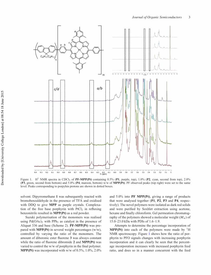
Journal of Organic Semiconductors 3
Figure 1. H1 NMR spectra in CDCl3 of PF-MPP(Pt) containing 0.5% (P1, purple, top), 1.0% (P2, cyan, second from top), 2.0%(P3, green, second from bottom) and 5.0% (P4, maroon, bottom) w/w of MPP(Pt). PF observed peaks (top right) were set to the samelevel. Peaks corresponding to porpyhin protons are shown in dotted boxes.
solvent. Dipyrromethane 1 was subsequently reacted withbromobenzaldehyde in the presence of TFA and oxidisedwith DDQ to give MPP as purple crystals. Complexa-tion of the free base porphyrin with PtCl2 in refluxingbenzonitrile resulted in MPP(Pt) as a red powder.
Suzuki polymerisation of the monomers was realisedusing Pd(OAc)2 with PPh3 as catalyst in the presence ofAliquat 336 and base (Scheme 2). PF-MPP(Pt) was pre-pared with MPP(Pt) in several weight percentages (w/w),controlled by varying the ratio of the monomers. Theamount of diboronic ester fluorene 3 was always constantwhile the ratio of fluorene dibromide 2 and MPP(Pt) wasvaried to control the w/w of porphyrin in the final polymer.MPP(Pt) was incorporated with w/w of 0.5%, 1.0%, 2.0%
and 5.0% into PF MPP(Pt), giving a range of productsthat were analysed together (P1, P2, P3 and P4, respec-tively). The novel polymers were isolated as dark red solidsand were purified by Soxhlet extraction using acetone,hexane and finally chloroform. Gel permeation chromatog-raphy of the polymers showed a molecular weight (Mw) of15.0–23.0 kDa with PDIs of 1.6–1.9.
Attempts to determine the percentage incorporation ofMPP(Pt) into each of the polymers were made by 1HNMR spectroscopy. Figure 1 shows how the ratio of por-phyrin to PFO signals changes with increasing porphyrinincorporation and it can clearly be seen that the percent-age incorporation increases with increased porphyrin feedratio, and does so in a manner concurrent with the feed
Dow
nloa
ded
by [U
nive
rsity
Col
lege
Lon
don]
at 0
8:54
18
June
201
5

4 D.M.E. Freeman et al.
Table 1. Synthetic results of polymerisation.
Incorporation ratio
w/w porphyrin FeedPolymer (%)a ratiob Mn (kDa)c Mw (kDa)c PDIc
P1 0.5 0.2 8.0 15 1.8P2 1.0 0.3 11 20 1.8P3 2.0 0.9 11 17 1.6P4 5.0 2.2 12 23 1.9
aDetermined by reaction stoichiometry.bDetermined by 1H NMR spectroscopy.cDetermined by SEC(PS) using PhCl eluent.
ratios. The estimated incorporation values are shown inTable 1 and are based on the ratio between the alkyl protonsclosest to fluorene and the most downfield pyrrolic protonpeaks, these being the most isolated. As the feed ratio isincreased, so does the incorporation ratio by an equivalentamount. This shows good evidence that the polymers areas expected relative to each other and represent a goodrange of porphyrin incorporation. The values are lowerthan the corresponding feed ratio, however, low incorpo-ration to feed ratios have been shown before on similarsystems.[21] It is thought that this discrepancy is primar-ily a result of errors associated with the NMR spectraintegration, rather than lower than the expected porphyrinincorporation, due to the good solubility of MPP(Pt) intoluene. By comparing the MPP(Pt) peaks in the poly-mers to monomeric MPP(Pt) and MPP, the peaks maybe tentatively identified. The four protons a–d come at8.1, 8.4, 8.9 and 9.1 ppm and can be seen as the inten-sity of the aromatic region is increased. All four shiftsare further downfield than MPP(Pt) as a monomer. Pro-ton e is expected to be under the much larger PFO peaks.The furthest downfield peaks (8.9 and 9.1 ppm) have beenassigned as c and d and the remaining peaks at 8.1 and8.4 ppm have been assigned as a and b. These assignmentsare based on the ordering of peaks of previous compounds(heteroaromatic protons were further downfield than aro-matic). As the level of porphyrin incorporation into thepolymer is increased from 0.5% to 5.0%, the relative inten-sities of the proton peaks increase, qualitatively showingthat the four porphyrin-containing polymers have a goodrange of w/w.
Methods for spectroscopy and LEDs are reported in theElectronic Supplementary Information (ESI).
The energy levels and molecular orbitals ofPF-MPP(Pt) were calculated by DFT B3LYP in silicousing basis set 6–31G* for C, H and N and LanL2DZfor Pt. Figure 2 shows the HOMO and LUMO levels ofan approximation of a porphyrin-containing portion of thepolymer. To reduce calculation times, the octyl chains ofPF have been replaced with methyl groups.
What is most apparent from the MO calculations is thedegree of localisation of the molecular orbitals to either the
Figure 2. HOMO and LUMO levels of PF-MPP(Pt).
porphyrin or fluorene portion of the molecule. The twistfrom porphyrin to phenyl to fluorene is such that conjuga-tion across the entire molecule is broken. While this willhave an overall negative impact on mobilities of the sys-tem, it does mean that the basic electronic characteristicsof both moieties are likely to be only mildly affected. How-ever, the HOMO, and to a smaller degree the LUMO, doboth show a mild degree of delocalisation from the por-phyrin to the main polymer chain, despite the large twist.It is expected therefore that energy transfer will be morefacilitated than the analogous blend of porphyrin and PFO.Significant LUMO contribution from the Pt d-orbitals canbe observed indicating that its role not only facilitates inter-system crossing but that the electronic transitions havemetal-to-ligand charge transfer characteristic.
3. Results and discussionWe report the absorption and emission spectra for thecopolymers P1–P4 thin films in Figure 3(b) and 3(c). Thecopolymers show an intense featureless band at 380 nm dueto the absorption of the PFO host polymer. In addition, thesamples show two features at about 512 and 540 nm that weattribute to the Q-bands of the metalloporphyrin.[22] Thesebands increase in intensity as the concentration of MPP-Pt
Dow
nloa
ded
by [U
nive
rsity
Col
lege
Lon
don]
at 0
8:54
18
June
201
5
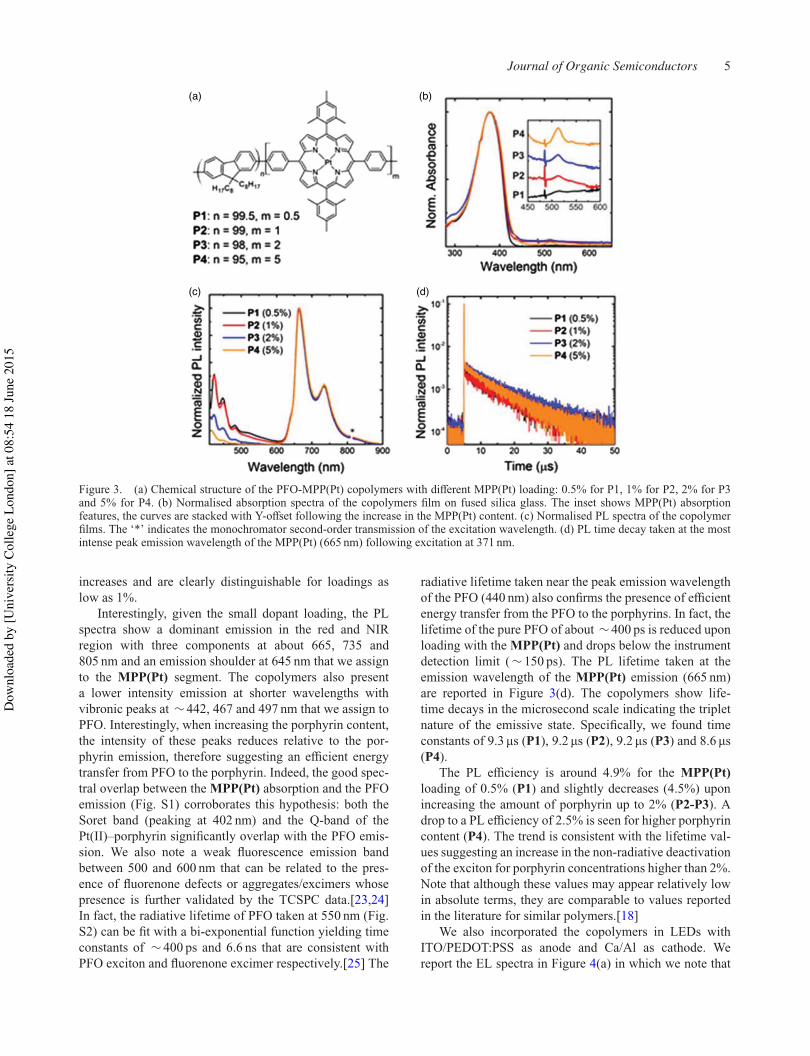
Journal of Organic Semiconductors 5
(a) (b)
(c) (d)
Figure 3. (a) Chemical structure of the PFO-MPP(Pt) copolymers with different MPP(Pt) loading: 0.5% for P1, 1% for P2, 2% for P3and 5% for P4. (b) Normalised absorption spectra of the copolymers film on fused silica glass. The inset shows MPP(Pt) absorptionfeatures, the curves are stacked with Y-offset following the increase in the MPP(Pt) content. (c) Normalised PL spectra of the copolymerfilms. The ‘*’ indicates the monochromator second-order transmission of the excitation wavelength. (d) PL time decay taken at the mostintense peak emission wavelength of the MPP(Pt) (665 nm) following excitation at 371 nm.
increases and are clearly distinguishable for loadings aslow as 1%.
Interestingly, given the small dopant loading, the PLspectra show a dominant emission in the red and NIRregion with three components at about 665, 735 and805 nm and an emission shoulder at 645 nm that we assignto the MPP(Pt) segment. The copolymers also presenta lower intensity emission at shorter wavelengths withvibronic peaks at ∼ 442, 467 and 497 nm that we assign toPFO. Interestingly, when increasing the porphyrin content,the intensity of these peaks reduces relative to the por-phyrin emission, therefore suggesting an efficient energytransfer from PFO to the porphyrin. Indeed, the good spec-tral overlap between the MPP(Pt) absorption and the PFOemission (Fig. S1) corroborates this hypothesis: both theSoret band (peaking at 402 nm) and the Q-band of thePt(II)–porphyrin significantly overlap with the PFO emis-sion. We also note a weak fluorescence emission bandbetween 500 and 600 nm that can be related to the pres-ence of fluorenone defects or aggregates/excimers whosepresence is further validated by the TCSPC data.[23,24]In fact, the radiative lifetime of PFO taken at 550 nm (Fig.S2) can be fit with a bi-exponential function yielding timeconstants of ∼ 400 ps and 6.6 ns that are consistent withPFO exciton and fluorenone excimer respectively.[25] The
radiative lifetime taken near the peak emission wavelengthof the PFO (440 nm) also confirms the presence of efficientenergy transfer from the PFO to the porphyrins. In fact, thelifetime of the pure PFO of about ∼ 400 ps is reduced uponloading with the MPP(Pt) and drops below the instrumentdetection limit ( ∼ 150 ps). The PL lifetime taken at theemission wavelength of the MPP(Pt) emission (665 nm)are reported in Figure 3(d). The copolymers show life-time decays in the microsecond scale indicating the tripletnature of the emissive state. Specifically, we found timeconstants of 9.3 µs (P1), 9.2 µs (P2), 9.2 µs (P3) and 8.6 µs(P4).
The PL efficiency is around 4.9% for the MPP(Pt)loading of 0.5% (P1) and slightly decreases (4.5%) uponincreasing the amount of porphyrin up to 2% (P2-P3). Adrop to a PL efficiency of 2.5% is seen for higher porphyrincontent (P4). The trend is consistent with the lifetime val-ues suggesting an increase in the non-radiative deactivationof the exciton for porphyrin concentrations higher than 2%.Note that although these values may appear relatively lowin absolute terms, they are comparable to values reportedin the literature for similar polymers.[18]
We also incorporated the copolymers in LEDs withITO/PEDOT:PSS as anode and Ca/Al as cathode. Wereport the EL spectra in Figure 4(a) in which we note that
Dow
nloa
ded
by [U
nive
rsity
Col
lege
Lon
don]
at 0
8:54
18
June
201
5
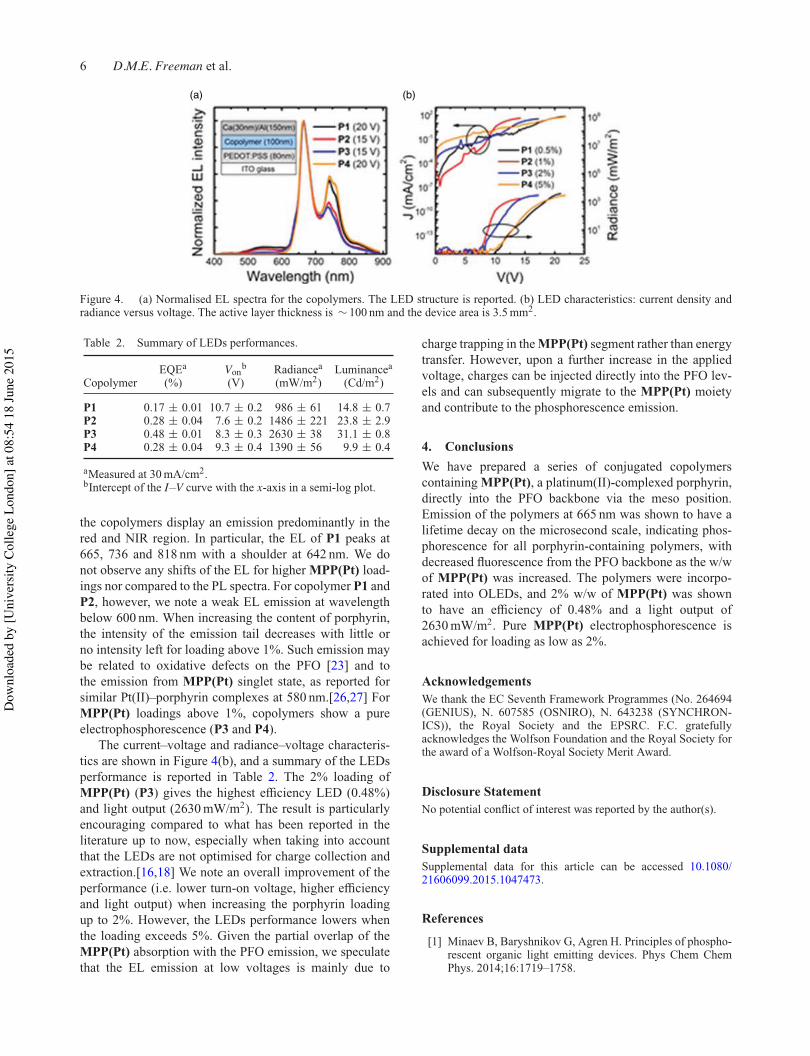
6 D.M.E. Freeman et al.
(a) (b)
Figure 4. (a) Normalised EL spectra for the copolymers. The LED structure is reported. (b) LED characteristics: current density andradiance versus voltage. The active layer thickness is ∼ 100 nm and the device area is 3.5 mm2.
Table 2. Summary of LEDs performances.
EQEa Vonb Radiancea Luminancea
Copolymer (%) (V) (mW/m2) (Cd/m2)
P1 0.17 ± 0.01 10.7 ± 0.2 986 ± 61 14.8 ± 0.7P2 0.28 ± 0.04 7.6 ± 0.2 1486 ± 221 23.8 ± 2.9P3 0.48 ± 0.01 8.3 ± 0.3 2630 ± 38 31.1 ± 0.8P4 0.28 ± 0.04 9.3 ± 0.4 1390 ± 56 9.9 ± 0.4
aMeasured at 30 mA/cm2.bIntercept of the I–V curve with the x-axis in a semi-log plot.
the copolymers display an emission predominantly in thered and NIR region. In particular, the EL of P1 peaks at665, 736 and 818 nm with a shoulder at 642 nm. We donot observe any shifts of the EL for higher MPP(Pt) load-ings nor compared to the PL spectra. For copolymer P1 andP2, however, we note a weak EL emission at wavelengthbelow 600 nm. When increasing the content of porphyrin,the intensity of the emission tail decreases with little orno intensity left for loading above 1%. Such emission maybe related to oxidative defects on the PFO [23] and tothe emission from MPP(Pt) singlet state, as reported forsimilar Pt(II)–porphyrin complexes at 580 nm.[26,27] ForMPP(Pt) loadings above 1%, copolymers show a pureelectrophosphorescence (P3 and P4).
The current–voltage and radiance–voltage characteris-tics are shown in Figure 4(b), and a summary of the LEDsperformance is reported in Table 2. The 2% loading ofMPP(Pt) (P3) gives the highest efficiency LED (0.48%)and light output (2630 mW/m2). The result is particularlyencouraging compared to what has been reported in theliterature up to now, especially when taking into accountthat the LEDs are not optimised for charge collection andextraction.[16,18] We note an overall improvement of theperformance (i.e. lower turn-on voltage, higher efficiencyand light output) when increasing the porphyrin loadingup to 2%. However, the LEDs performance lowers whenthe loading exceeds 5%. Given the partial overlap of theMPP(Pt) absorption with the PFO emission, we speculatethat the EL emission at low voltages is mainly due to
charge trapping in the MPP(Pt) segment rather than energytransfer. However, upon a further increase in the appliedvoltage, charges can be injected directly into the PFO lev-els and can subsequently migrate to the MPP(Pt) moietyand contribute to the phosphorescence emission.
4. ConclusionsWe have prepared a series of conjugated copolymerscontaining MPP(Pt), a platinum(II)-complexed porphyrin,directly into the PFO backbone via the meso position.Emission of the polymers at 665 nm was shown to have alifetime decay on the microsecond scale, indicating phos-phorescence for all porphyrin-containing polymers, withdecreased fluorescence from the PFO backbone as the w/wof MPP(Pt) was increased. The polymers were incorpo-rated into OLEDs, and 2% w/w of MPP(Pt) was shownto have an efficiency of 0.48% and a light output of2630 mW/m2. Pure MPP(Pt) electrophosphorescence isachieved for loading as low as 2%.
AcknowledgementsWe thank the EC Seventh Framework Programmes (No. 264694(GENIUS), N. 607585 (OSNIRO), N. 643238 (SYNCHRON-ICS)), the Royal Society and the EPSRC. F.C. gratefullyacknowledges the Wolfson Foundation and the Royal Society forthe award of a Wolfson-Royal Society Merit Award.
Disclosure StatementNo potential conflict of interest was reported by the author(s).
Supplemental dataSupplemental data for this article can be accessed 10.1080/21606099.2015.1047473.
References
[1] Minaev B, Baryshnikov G, Agren H. Principles of phospho-rescent organic light emitting devices. Phys Chem ChemPhys. 2014;16:1719–1758.
Dow
nloa
ded
by [U
nive
rsity
Col
lege
Lon
don]
at 0
8:54
18
June
201
5

Journal of Organic Semiconductors 7
[2] Baldo MA, O’Brien DF, You Y, Shoustikov A, Sibley S,Thompson ME, Forrest SR. Highly efficient phosphorescentemission from organic electroluminescent devices. Nature.1998;395:151–154.
[3] Baldo MA, Thompson ME, Forrest SR. High-efficiencyfluorescent organic light-emitting devices using a phospho-rescent sensitizer. Nature. 2000;403:750–753.
[4] Lane PA, Palilis LC, O’Brien DF, Giebeler C, Cadby AJ,Lidzey DG, Campbell AJ, Blau W, Bradley DDC. Ori-gin of electrophosphorescence from a doped polymer lightemitting diode. Phys Rev B. 2001;63:235206.
[5] Sudhakar M, Djurovich PI, Hogen-Esch TE, ThompsonME. Phosphorescence quenching by conjugated polymers.J Am Chem Soc. 2003;125:7796–7797.
[6] Chen X, Liao JL, Liang Y, Ahmed MO, Tseng HE, ChenSA. High-efficiency red-light emission from polyfluorenesgrafted with cyclometalated iridium complexes and chargetransport moiety. J Am Chem Soc. 2003;125:636–637.
[7] Sandee AJ, Williams CK, Evans NR, Davies JE, BoothbyCE, Kohler A, Friend RH, Holmes AB. Solution-processibleconjugated electrophosphorescent polymers. J Am ChemSoc. 2004;126:7041–7048.
[8] Morgado J, Cacialli F, Friend RH, Iqbal R, Yahioglu G,Milgrom LR, Moratti SC, Holmes AB. Tuning the red emis-sion of a soluble poly(p-phenylene vinylene) upon graft-ing of porphyrin side groups. Chem Phys Lett. 2000;325:552–558.
[9] Iqbal R, Moratti SC, Holmes AB, Yahioglu G, Milgrom LR,Cacialli F, Morgado J, Friend RH. Synthesis of porphyrin-PPV copolymers for application in LEDs. J Mater Sci–Mater Electron. 2000;11:97–103.
[10] Morgado J, Cacialli F, Iqbal R, Moratti SC, Holmes AB,Yahioglu G, Milgrom LR, Friend RH. Förster energytransfer and control of the luminescence in blends ofan orange-emitting poly(p-phenylenevinylene) and a red-emitting tetraphenylporphyrin. J Mater Chem. 2001;11:278–283.
[11] Fenwick O, Sprafke JK, Binas J, Kondratuk DV, Di Sta-sio F, Anderson HL, Cacialli F. Linear and cyclic porphyrinhexamers as near-infrared emitters in organic light-emittingdiodes. Nano Lett. 2011;11:2451–2456.
[12] Li P, Fenwick O, Yilmaz S, Breusov D, Caruana DJ, AllardS, Scherf U, Cacialli F. Dual functions of a novel low-gappolymer for near infra-red photovoltaics and light-emittingdiodes. Chem Commun. 2011;47:8820–8822.
[13] Steckler TT, Fenwick O, Lockwood T, Andersson MR,Cacialli F. Near-infrared polymer light-emitting diodesbased on low-energy gap oligomers copolymerized intoa high-gap polymer host. Macromol Rapid Comm.2013;34:990–996.
[14] Steckler TT, Lee MJ, Chen Z, Fenwick O, AnderssonMR, Cacialli F, Sirringhaus H. Multifunctional materialsfor OFETs, LEFETs and NIR PLEDs. J Mater Chem C.2014;2:5133–5141.
[15] Tregnago G, Flechon C, Choudhary S, Gozalvez C,Mateo-Alonso A, Cacialli F. Virtually pure near-infraredelectroluminescence from exciplexes at polyfluorene/hexaazatrinaphthylene interfaces. Appl Phys Lett. 2014;105:143304.
[16] Hou Q, Zhang Y, Li FY, Peng JB, Cao Y. Redelectrophosphorescence of conjugated organoplatinum(II)polymers prepared via direct metalation of poly(fluorene-co-tetraphenylporphyrin) copolymers. Organometallics.2005;24:4509–4518.
[17] Xiang H, Zhou L, Feng Y, Cheng J, Wu D, Zhou X. Tun-able fluorescent/phosphorescent platinum(II) porphyrin–fluorene copolymers for ratiometric dual emissive oxygensensing. Inorg Chem. 2012;51:5208–5212.
[18] Zhuang WL, Zhang Y, Hou Q, Wang L, Cao Y. High-efficiency, electrophosphorescent polymers with porphyrin–platinum complexes in the conjugated backbone: syn-thesis and device performance. J Polym Sci Pol Chem.2006;44:4174–4186.
[19] Yang R, Tian R, Yan J, Zhang Y, Yang J, Hou Q,Yang W, Zhang C, Cao Y. Deep-red electroluminescentpolymers: synthesis and characterization of new low-band-gap conjugated copolymers for light-emitting diodes andphotovoltaic devices. Macromolecules. 2005;38:244–253.
[20] Lindsey JS. Synthetic routes to meso-patterned porphyrins.Acc Chem Res. 2009;43:300–311.
[21] Jiang B, Jones WE. Synthesis and characterization of a con-jugated copolymer of poly(phenylenevinylene) containing ametalloporphyrin incorporated into the polymer backbone.Macromolecules. 1997;30:5575–5581.
[22] Mink LM, Neitzel ML, Bellomy LM, Falvo RE, BoggessRK, Trainum BT, Yeaman P. Platinum(II) and platinum(IV)porphyrin complexes: synthesis, characterization, and elec-trochemistry. Polyhedron. 1997;16:2809–2817.
[23] Becker K, Lupton JM, Feldmann J, Nehls BS, GalbrechtF, Gao DQ, Scherf U. On-chain fluorenone defect emissionfrom single polyfluorene molecules in the absence of inter-molecular interactions. Adv Funct Mater. 2006;16:364–370.
[24] Pei QB, Yang Y. Efficient photoluminescence and electrolu-minescence from a soluble polyfluorene. J Am Chem Soc.1996;118:7416–7417.
[25] Sims M, Bradley DDC, Ariu M, Koeberg M, Asi-makis A, Grell M, Lidzey DG. Understanding the ori-gin of the 535 nm emission band in oxidized poly(9,9-dioctylfluorene): the essential role of inter-chain/inter-segment interactions. Adv Funct Mater. 2004;14:765–781.
[26] Kwong RC, Sibley S, Dubovoy T, Baldo M, Forrest SR,Thompson ME. Efficient, saturated red organic light emit-ting devices based on phosphorescent platinum(II) por-phyrins. Chem Mater. 1999;11:3709–3713.
[27] Ponterini G, Serpone N, Bergkamp MA, Netzel TL. Com-parison of radiationless decay processes in osmium andplatinum porphyrins. J Am Chem Soc. 1983;105:4639–4645.
Dow
nloa
ded
by [U
nive
rsity
Col
lege
Lon
don]
at 0
8:54
18
June
201
5

217

218
Appendix 2: Highly red-shifted NIR emission from a novel anthracene conjugated polymer backbone containing Pt(II) porphyrins


219

230
Appendix 3: Synthesis and Exciton Dynamics of Donor-Orthogonal Acceptor Conjugated Polymers: Reducing the Singlet–Triplet Energy Gap