MANHOLE BRACES - Pages - Welcome to The Ohio …€¦ · Lifting Sling When required MHB must be...
16
3330 S. Sam Houston Pkwy ♦ Houston, Texas 77047 (713)943-0750 ♦ USA Toll Free 1-800-231-6662 ♦Fax (713)943-8483 Www.speedshore.com PRINTED IN U.S.A. COPYRIGHT 2005 SPEED SHORE CORPORATION. ALL RIGHTS RESERVED MANHOLE BRACES DETAILED SPECIFICATIONS SPEC BROCHURE INSTALLATION AND REMOVAL MANUFACTURE’S TABULATED DATA
Transcript of MANHOLE BRACES - Pages - Welcome to The Ohio …€¦ · Lifting Sling When required MHB must be...

3330 S. Sam Houston Pkwy ♦ Houston, Texas 77047 (713)943-0750 ♦ USA Toll Free 1-800-231-6662 ♦Fax (713)943-8483
Www.speedshore.com
PRINTED IN U.S.A. COPYRIGHT 2005 SPEED SHORE CORPORATION. ALL RIGHTS RESERVED
MANHOLE BRACES
DETAILED SPECIFICATIONS SPEC BROCHURE
INSTALLATION AND REMOVAL MANUFACTURE’S TABULATED DATA

3" MANHOLE BRACETM SYSTEMSDetailed Specifications
Units specified herein shall be fully assembled, adjustable, personnel protective devices specifically designed andprofessionally engineered to provide excavation safety protection for workers. These units shall be in fullcompliance with all applicable Federal Occupational Safety and Health Administration (OSHA) Regulations.
DESCRIPTION
Units consist of four (4) 3" I.D. aluminum hydraulic cylinders encased in telescoping, steel square box tubing andattached end-to-end to form an expandable rectangular unit.
HYDRAULIC CYLINDER CROSS-BRACES
1. Cylinders shall be a minimum of 3" I.D. and shall have an allowable load of not less than 42,000 poundsaxial compression load with a 1.5 safety factor.
2. Cylinders shall be furnished with aluminum oversleeves for protection of the piston rod through itscomplete stroke.
3. Cylinders barrels shall be composed of 6061-T6 aluminum alloy drawn seamless.4. Cylinders shall be fitted with a wiper guide assembly to thoroughly clean the smooth exterior of the piston
rod before entering the cylinder.5. O-ring seals in the cylinder pads are to be located in the annular space between the cylinder barrel and the
inside cylinder pad wall.6. Cylinders shall be equipped with a hollow piston rod to allow hydraulic pressure throughout the system for
maximum strength and prevention of low pressure leakage.7. The piston head seal shall be a loaded O-ring design for optimum seal and prevention of low pressure
leakage.8. Cylinder barrel shall be permanently date stamped by manufacturer.9. Oversleeve, cylinder barrel, cylinder pad, and socket pad shall be permanently stamped with
manufacturers name.
GENERAL NOTES
1. Cylinders shall be pinned to brackets at each corner of the rectangular unit such that a pivoting action isinherent in the design to allow the unit to conform to irregular vertical walls.
2. Each corner bracket shall be furnished with lifting eyes to facilitate installation and removal of the units.
ACCESSORIES
1. Hydraulic Hand Pumps or Battery Powered Automatic Pumpsa. Hydraulic pumps shall be a minimum of 5 gallon fluid capacity, complete with calibrated gauge,
hose, valves and fittings.b. Pump gauge shall have a green color coded face plate indicating normal operating range of 750 -
1,500 psi.c. Pump hose shall be a minimum of 12' in length with spring guards and a minimum working
pressure of 5,000 psi.
Page 1 of 2

ACCESSORIES (continued)
2. Release Tools and Removal HooksManufacturer supplying goods must have available specially designed tools to facilitateabove-ground installation and removal of all units.
3. Hose Bridle Assembliesa. Manufacturer supplying goods must have available specially designed hose bridle assemblies to
allow expansion of all cylinders simultaneously using a single hydraulic pump.b. Hose bridle assemblies shall have a minimum working pressure of 5,000 psi.c. Hose bridle shall be fitted with shut off valves for independent cylinder control, fluid release and
fluid recovery.
EQUIVALENCIES
1. Refer to Speed Shore Corporation's technical data for specific models and accessories.2. These specifications are intended to establish a standard of quality and performances.3. Designs which meet or exceed these specifications shall be considered in compliance.
PARTS AND SERVICE
1. Replacement parts must be available for shipment within five working days of Purchase Order.2. Parts List will be furnished upon request.
PRODUCT LIABILITY
The manufacturer under these specifications shall be required to carry a minimum one million dollars($1,000,000.00) product liability insurance policy with bid award being contingent upon proof of coverage.
EXPERIENCE
The manufacturer under these specifications shall be required to furnish documented proof of professional expertiseand competence in excavation safety product experience and manufacturing for a minimum of five (5) years. Wereserve the right to request from the apparent successful manufacturer a client list for the purpose of obtainingreferences on quality of products furnished and service history.
DELIVERY
Delivery of all equipment, features and accessories specified herein is to be made within sixty (60) days after receiptof Purchase Order.
WARRANTY
The successful bidder under these specifications shall furnish a minimum one (1) year warranty on all parts andlabor.
TRAINING
The manufacturer under these specifications shall provide installation instructions, recommended uses andmaintenance instructions to the solicitor upon delivery of the unit(s).

USA TOLL FREE (800) 231-6662 (713) 943-0750 FAX (713) 943-8483 www.speedshore.com
Speed Shore Manhole Braces combine the benefits of aluminum hydraulic shoring with the ruggedness of steel box tubing in the most effective support system ever de-veloped for shaft excavations. Specifically designed for shoring square and rectangu-lar excavations, this perimeter support sys-tem provides for an unobstructed shaft, and is generally used to secure pits for pump stations, the installation or rehabilitation of manholes, tanks and vaults, or the opera-tion of trenchless technology equipment.
Manhole Braces, used in conjunction with appropriate sheeting, provide the active support necessary to secure safe excava-tions in less stable soils. Available in a wide variety of sizes and capacities, Manhole Braces are composed of modular sections for ease of assembly and transport. Man-hole Braces feature 4-way hydraulic support with high-yield telescoping steel sections, and 4-way hose bridles for simultaneous
Additional Standard Manhole Brace Features: • 4-Way hydraulic support with high strength,
telescoping steel tubing over-sleeves. • Non-rigid corner brackets. • Individual legs for on site assembly and easy
transportation. • Quick connect pins and keepers. • Flexibility to fit square or rectangular excava-
tions. • 4-Way hose bridal for simultaneous cylinder
pressurization • 4-corner lifting eye for installation and removal. • HVP-2000 high volume hand pump or HP-200
electric pump.

USA TOLL FREE (800) 231-6662 (713) 943-0750 FAX (713) 943-8483 www.speedshore.com
3” MANHOLE BRACE
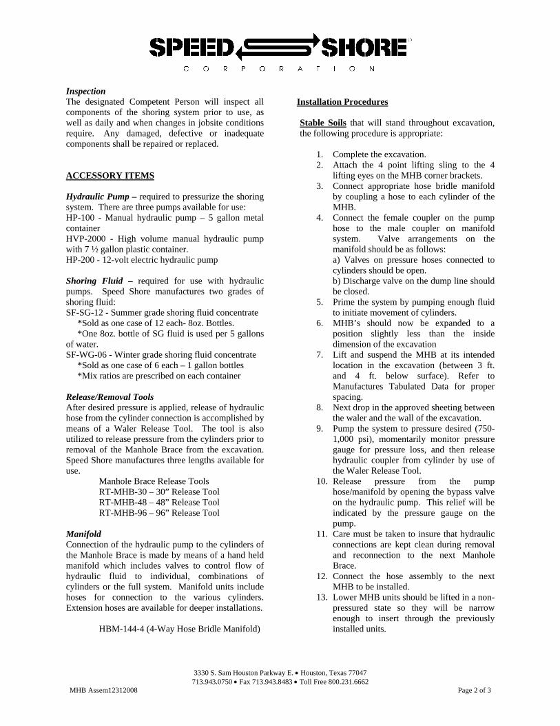
Notes: 1. Figures in the chart below are collapsed (retracted) leg dimensions. 2. All legs have a 3” internal cylinder with a 3’ stroke. 3. “X” and “Y” in the chart below denote the collapsed length of each side. 4. 3” Manhole Braces have 6” steel box tubing oversleeves.
Example: Model Number: MHB-3-0810
A complete 8’ X 10’ MHB assembly comes with:
4 Legs with a maximum expansion to 11’ X 13’ (3’ Cylinder stroke) Weight is 1,595 lbs.
X Y
WEIGHT Y
X 6’
6’ 1,265 7’
7’ 1,320 1,375 8’
8’ 1,375 1,430 1,485 9’
9’ 1,430 1,485 1,540 1,595 10’
10’ 1,485 1,540 1,595 1,650 1,705 11’
11’ 1,540 1,595 1,650 1,705 1,760 1,815 12’
12’ 1,595 1,650 1,705 1,760 1,815 1,870 1,925 13’
13’ 1,650 1,705 1,760 1,815 1,870 1,925 1,980 2,035 14’
14’ 1,705 1,760 1,815 1,870 1,925 1,980 2,035 2,090 2,145 15’
15’ 1,760 1,815 1,870 1,925 1,980 2,035 2,090 2,145 2,200 2,255 16’
16’ 1,815 1,870 1,925 1,980 2,035 2,090 2,145 2,200 2,255 2,310 2,365 17’
17’ 1,870 1,925 1,980 2,035 2,090 2,145 2,200 2,255 2,310 2,365 2,420 2,475
HVP-2000
HP-200

3330 S. Sam Houston Parkway E. • Houston, Texas 77047 713.943.0750 • Fax 713.943.8483 • Toll Free 800.231.6662
MHB Assem12312008 Page 1 of 3
4-WAY MANHOLE BRACE INSTALLATION and REMOVAL PROCEDURES GENERAL NOTES Speed Shore 4-way Manhole Braces (MHB) are hydraulically applied shoring devices designed to be installed in a pit configuration to support weaker soils that require sheeting. They are manufactured in compliance with the Federal Occupational Safety and Health Administration (OSHA) Standards. MHB are designed to support a uniform lateral earth pressure over the full load zone area of each MHB leg. Lateral Earth Pressure being a function of the equivalent weight effect of the soil and the depth of excavation. These MHB are designed as simple span beams between the hydraulic cylinders which support the full load placed upon the system. MHB Systems are composed of four horizontal legs with 2” diameter or 3” diameter aluminum hydraulic cylinders inside of steel inner and over sleeves. Cylinders are manufactured from 6061-T6 alloy and have a safe working capacity of 23,000 pounds for 2” diameter cylinders and 42,000 pounds for 3” diameter cylinders. Normal working pressure in the cylinder is 750 to 1,000 psi. Sheeting is required and serves to contain the raveling effect of cohesive soils and prevent the movement of non-cohesive soils which are likely to flow. The sheeting also transfers the soil loading to the MHB which in turn transfers the load to the cylinders, establishing a balance between the opposing shored excavation faces, with the cylinders
acting as a cross braces. Sheeting may be plywood, timber, steel, aluminum, fiberglass or any other material of equal structural quality as determined by accepted engineering practices, and is not normally attached to the MHB. Refer to Manufactures Tabulated Data for approved sheeting. The designated Competent Person shall ensure that all excavation work is done in compliance with the requirements of the OSHA standard for excavations and manufacturer's tabulated data. They will inspect all components of the shoring system prior to use, as well as daily and when changes in jobsite conditions require. Any damaged, defective or inadequate components shall be repaired or replaced. A TRAINED COMPETENT PERSON SHALL: SUPERVISE ALL EXCAVATION OPERATIONS, ENSURE THAT ALL PERSONNEL ARE WORKING IN SAFE CONDITIONS, AND HAVE THOROUGH KNOWLEDGE OF THE APPROPIATE TABULATED DATA. THE COMPETENT PERSON SHALL HAVE THEAUTHORITY TO STOP WORK WHEN IT IS UNSAFE FOR WORKERS TO ENTER AN EXCAVATION. Manufacturers Tabulated Data Speed Shore's Tabulated Data complies with the O.S.H.A. standards as stated in the Code of Federal Regulations 29, Part 1926, Subpart P - Excavations, Section 1926.652(c)(2). This data shall only be used by the contractor's competent person in the selection of Speed Shore Manhole Braces. The competent person shall be experienced and knowledgeable in trenching and excavation procedures, Depth of Operation Manhole Braces are designed to support lateral earth pressure through the strength of its hydraulic cylinders. Lateral Earth Pressure being a function of the equivalent weight effect of the soil and the depth of excavation. Manhole Braces may be used to shore trenches up to 25 feet in depth in Type A, B, C-60 or C type soils. Consult Speed Shore manufacturer's tabulated data for actual depth rating. Lifting Sling When required MHB must be lifted with a removable sling manufactured in compliance with the requirements of OSHA standard for rigging equipment, and rated for the anticipated load. Please note that tie-down chains and other improvised slings are not appropriate as lifting devices.
3330 S. Sam Houston Parkway E. • Houston, Texas 77047 713.943.0750 • Fax 713.943.8483 • Toll Free 800.231.6662
MHB Assem12312008 Page 2 of 3
Inspection The designated Competent Person will inspect all components of the shoring system prior to use, as well as daily and when changes in jobsite conditions require. Any damaged, defective or inadequate components shall be repaired or replaced. ACCESSORY ITEMS Hydraulic Pump – required to pressurize the shoring system. There are three pumps available for use: HP-100 - Manual hydraulic pump – 5 gallon metal container HVP-2000 - High volume manual hydraulic pump with 7 ½ gallon plastic container. HP-200 - 12-volt electric hydraulic pump Shoring Fluid – required for use with hydraulic pumps. Speed Shore manufactures two grades of shoring fluid: SF-SG-12 - Summer grade shoring fluid concentrate *Sold as one case of 12 each- 8oz. Bottles. *One 8oz. bottle of SG fluid is used per 5 gallons of water. SF-WG-06 - Winter grade shoring fluid concentrate *Sold as one case of 6 each – 1 gallon bottles *Mix ratios are prescribed on each container Release/Removal Tools After desired pressure is applied, release of hydraulic hose from the cylinder connection is accomplished by means of a Waler Release Tool. The tool is also utilized to release pressure from the cylinders prior to removal of the Manhole Brace from the excavation. Speed Shore manufactures three lengths available for use. Manhole Brace Release Tools RT-MHB-30 – 30” Release Tool RT-MHB-48 – 48” Release Tool RT-MHB-96 – 96” Release Tool Manifold Connection of the hydraulic pump to the cylinders of the Manhole Brace is made by means of a hand held manifold which includes valves to control flow of hydraulic fluid to individual, combinations of cylinders or the full system. Manifold units include hoses for connection to the various cylinders. Extension hoses are available for deeper installations.
HBM-144-4 (4-Way Hose Bridle Manifold)
Installation Procedures Stable Soils that will stand throughout excavation, the following procedure is appropriate:
1. Complete the excavation. 2. Attach the 4 point lifting sling to the 4
lifting eyes on the MHB corner brackets. 3. Connect appropriate hose bridle manifold
by coupling a hose to each cylinder of the MHB.
4. Connect the female coupler on the pump hose to the male coupler on manifold system. Valve arrangements on the manifold should be as follows: a) Valves on pressure hoses connected to cylinders should be open. b) Discharge valve on the dump line should be closed.
5. Prime the system by pumping enough fluid to initiate movement of cylinders.
6. MHB’s should now be expanded to a position slightly less than the inside dimension of the excavation
7. Lift and suspend the MHB at its intended location in the excavation (between 3 ft. and 4 ft. below surface). Refer to Manufactures Tabulated Data for proper spacing.
8. Next drop in the approved sheeting between the waler and the wall of the excavation.
9. Pump the system to pressure desired (750-1,000 psi), momentarily monitor pressure gauge for pressure loss, and then release hydraulic coupler from cylinder by use of the Waler Release Tool.
10. Release pressure from the pump hose/manifold by opening the bypass valve on the hydraulic pump. This relief will be indicated by the pressure gauge on the pump.
11. Care must be taken to insure that hydraulic connections are kept clean during removal and reconnection to the next Manhole Brace.
12. Connect the hose assembly to the next MHB to be installed.
13. Lower MHB units should be lifted in a non-pressured state so they will be narrow enough to insert through the previously installed units.
3330 S. Sam Houston Parkway E. • Houston, Texas 77047 713.943.0750 • Fax 713.943.8483 • Toll Free 800.231.6662
MHB Assem12312008 Page 3 of 3
14. Insert lower MHB through those installed and position at desired elevation. Repeat above procedure to pressure unit and remove hoses.
Less-Stable Soils that tend to fail as digging progresses and do not present a near vertical excavation face or wall, may require that sheeting be driven prior to beginning excavation.
1. Start digging a pilot cut 2-3 feet deep. 2. Follow steps 2 through 7 under stable soils. 3. Drive the sheeting around the perimeter of
the first MHB in the excavation to the desire depth of the excavation.
4. Excavate from within the driven sheeting to the final required depth or to the depth of the next MHB to be installed.
5. Insert the second MHB through the previously installed unit and complete installation.
6. Lower units may be installed following the above procedure.
Observe that the undisturbed soil will support sheeting prior to installation of the first MHB. Thereafter, installed MHB’s will support the upper area of the sheeting while undisturbed soil supports the lower area. PLEASE NOTE: Final determination of the installation procedures will be up to the Competent Person to follow safe installation procedures depending on soil and site conditions. Also on the installation of multiple MHB’s in a vertical plane, the MHB’s may be stacked on top of each other, lifting sling attached to the bottom unit, and the multiple units lifted and installed at the same time. Removal Procedures To remove Manhole Braces from the excavation the following procedure is suggested:
1. Connect lifting slings to lifting eyes on the bottom unit.
2. From the surface of the excavation, relieve pressure on the cylinders in the MHB by use of the MHB Release Tool. The tool is used to press on the male connector on the tip of the cylinder allowing shoring fluid to escape to the excavation. Initially release a small amount of fluid from the cylinder and
observe the shoring system for any indication of soil movement. Take care to remain in a safe position during continued pressure release. After observing the effect of pressure release upon the system, complete fluid removal until the cylinder has been compressed to the desired position.
3. After pressure has been relieved on the cylinders, lift the unit up to the next MHB above. Repeat pressure relief on that MHB and lift if by means of the unit previously released.
4. Continue this procedure until all units are removed from the excavation.
5. Disconnect and store the MHB assembly and manifold.
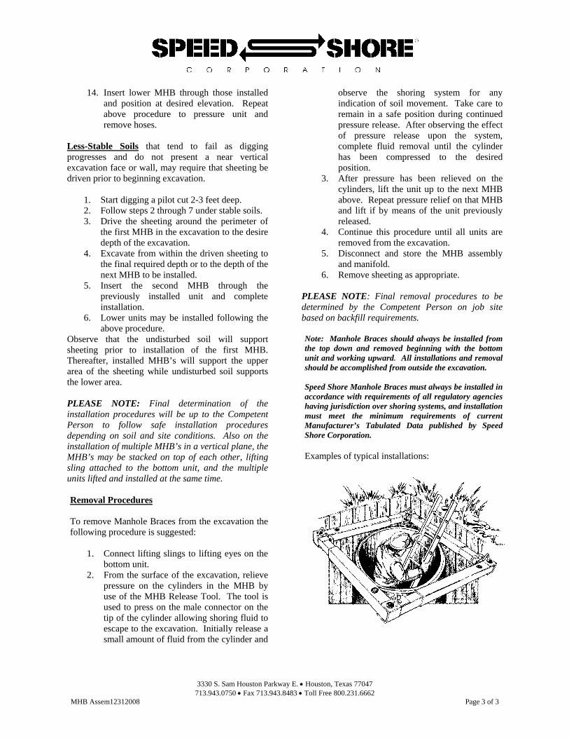
6. Remove sheeting as appropriate. PLEASE NOTE: Final removal procedures to be determined by the Competent Person on job site based on backfill requirements. Note: Manhole Braces should always be installed from the top down and removed beginning with the bottom unit and working upward. All installations and removal should be accomplished from outside the excavation. Speed Shore Manhole Braces must always be installed in accordance with requirements of all regulatory agencies having jurisdiction over shoring systems, and installation must meet the minimum requirements of current Manufacturer’s Tabulated Data published by Speed Shore Corporation. Examples of typical installations:

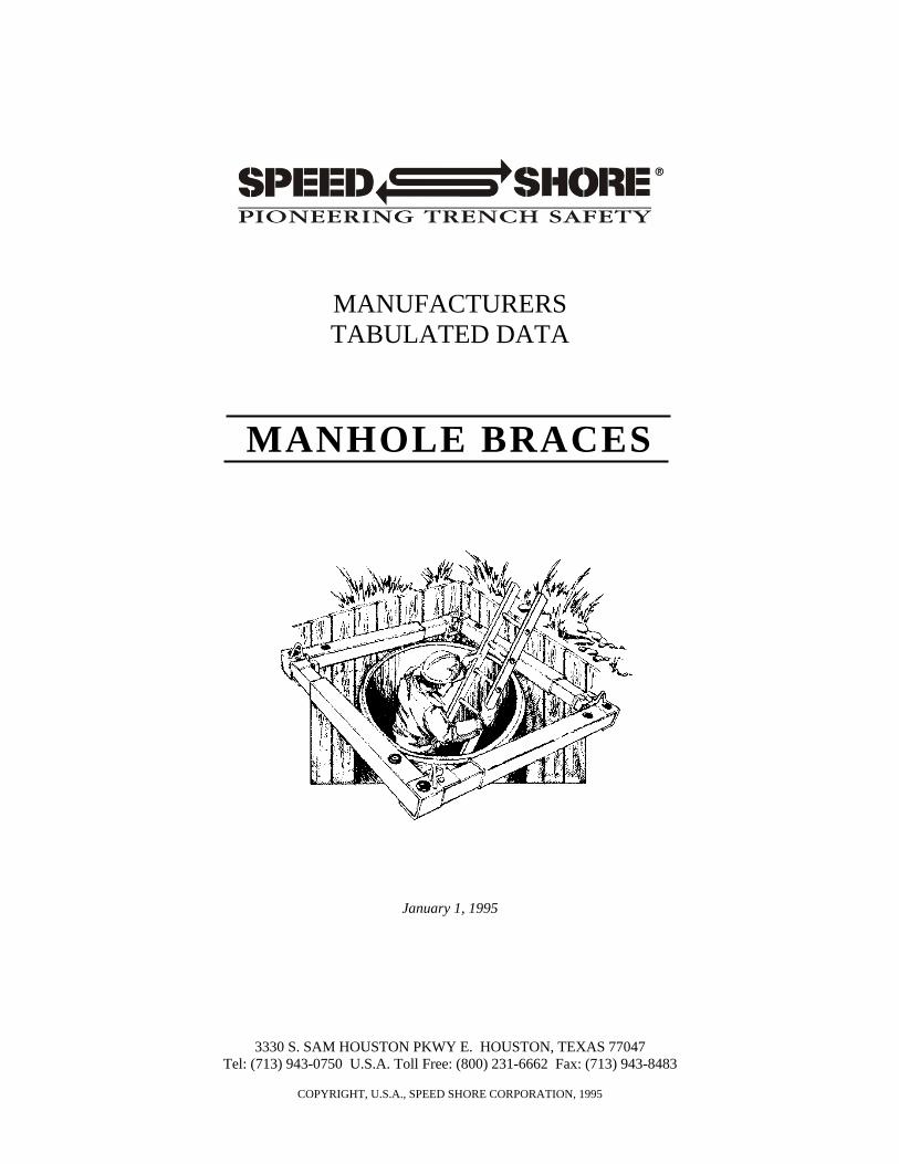
MANUFACTURERS TABULATED DATA
MANHOLE BRACES
January 1, 1995
3330 S. SAM HOUSTON PKWY E. HOUSTON, TEXAS 77047
Tel: (713) 943-0750 U.S.A. Toll Free: (800) 231-6662 Fax: (713) 943-8483
COPYRIGHT, U.S.A., SPEED SHORE CORPORATION, 1995

January 1, 1995 MANHOLE BRACES Page 2 of 6
COPYRIGHT, U.S.A., SPEED SHORE CORPORATION, 1995
W A R N I N G
EXCAVATION PROCEDURES MAY BE VERY DANGEROUS A TRAINED COMPETENT PERSON SHALL: SUPERVISE ALL EXCAVATION
OPERATIONS, ENSURE THAT ALL PERSONNEL ARE WORKING IN SAFE CONDITIONS, AND HAVE THOROUGH KNOWLEDGE OF THIS TABULATED DATA. THE COMPETENT PERSON SHALL HAVE THE AUTHORITY TO STOP WORK WHEN IT IS UNSAFE FOR WORKERS TO ENTER AN EXCAVATION.
ALL PERSONNEL SHALL BE TRAINED IN CORRECT EXCAVATION PROCEDURES,
PROPER USE OF THE PROTECTIVE SYSTEM AND ALL SAFETY PRECAUTIONS. EXCAVATIONS AND PROTECTIVE SYSTEMS SHALL BE INSPECTED A MINIMUM OF
ONCE EACH WORKING DAY AND WHENEVER THERE IS A CHANGE OF SOIL, WATER OR OTHER JOB SITE CONDITIONS.
ALL LIFTING AND PULLING EQUIPMENT, INCLUDING CABLES, SLINGS, CHAINS,
SHACKLES AND SAFETY HOOKS SHALL BE EVALUATED FOR SUITABILITY AND CAPACITY, AND SHALL BE INSPECTED FOR DAMAGE OR DEFECTS PRIOR TO USE.
ALL INSTALLATION AND REMOVAL OF SHORING AND SHIELDING SHALL BE FROM
ABOVE GROUND ONLY. DO NOT ALLOW PERSONNEL TO ENTER AN EXCAVATION THAT IS NOT PROPERLY
SHORED, SHIELDED OR SLOPED. PERSONNEL SHALL ALWAYS WORK WITHIN THE SHORING AND SHIELDING.
PERSONNEL SHALL NOT STAND ON THE EDGE OF AN UNSHORED EXCAVATION. ALL PERSONNEL SHALL ENTER AND EXIT EXCAVATIONS ONLY WITHIN SHIELDED
OR SHORED AREAS. THIS SPEED SHORE TABULATED DATA IS A GENERAL SET OF GUIDELINES AND TABLES TO ASSIST THE COMPETENT PERSON IN SELECTING A SAFETY SYSTEM AND THE PROPER SHORING OR SHIELDING EQUIPMENT. THE COMPETENT PERSON HAS SOLE RESPONSIBILITY FOR JOB SITE SAFETY AND THE PROPER SELECTION AND INSTALLATION AND REMOVAL OF THE SHORING OR SHIELDING EQUIPMENT. THIS TABULATED DATA IS NOT INTENDED TO BE USED AS A JOB SPECIFIC EXCAVATION SAFETY PLAN, BUT SHALL BE USED BY THE COMPETENT PERSON TO SUPPLEMENT HIS TRAINING, HIS EXPERIENCE AND HIS KNOWLEDGE OF THE JOB CONDITIONS AND SOIL TYPE.

January 1, 1995 MANHOLE BRACES Page 3 of 6
COPYRIGHT, U.S.A., SPEED SHORE CORPORATION, 1995
SPEED SHORE TABULATED DATA
1.0 SCOPE
1.1 Speed Shore's Tabulated Data complies with the O.S.H.A. standards as stated in the Code of Federal
Regulations 29, Part 1926, Subpart P - Excavations, Section 1926.652(c)(2). This data shall only be used by the contractor's competent person in the selection of Speed Shore Manhole Braces, spacing, size of sleeves and sheeting requirements. The competent person shall be experienced and knowledgeable in trenching and excavation procedures, soil identification and in the use of Manhole Braces.
1.2 All personnel involved in the installation, removal and use of Manhole Braces shall be trained in their use and advised of appropriate safety procedures. All operating instruction must be followed.
1.3 This data is based in whole or in part, upon requirements stated in CFR 29, Part 1926 and applicable portions of CFR 29, Part 1910. The competent person shall know and understand the requirements of those parts before using this data.
1.4 Whenever there is a variance between this Tabulated Data and CFR 29, Part 1926, Subpart P - Excavations, this Tabulated Data shall take precedence. Whenever a topic or subject is not contained in this Tabulated Data, the competent person shall refer to CFR 29, Part 1926, Subpart P - Excavations.
1.5 Tables MHB-2 shall be used only in excavations with soil conditions as noted. For other soil and excavation conditions and depths, site-specific engineered designs are required. Contact Speed Shore Corporation for assistance
1.6 This Tabulated Data is applicable for standard products manufactured exclusively by Speed Shore and may only be used with Speed Shore manufactured products. Any modification or repair of Speed Shore products not specifically authorized by Speed Shore Corporation voids this data.
1.7 This data refers to the Code of Federal Regulations, 29, Parts 1910 and 1926. In states that have their own state O.S.H.A. refer to similar regulations in the current construction rules published by the state office of Occupational Health and Safety.
2.0 DEFINITIONS (RE: CFR 29, Part 1926.32 Definitions) - RESTATED FOR EMPHASIS
2.1 1926.32 (f) "competent person" means one who is capable of identifying existing and predictable hazards in the surroundings or working conditions which are unsanitary, hazardous or dangerous to employees; and who has authorization to take prompt corrective measures to eliminate them.
2.2 1926.32 (p) "Shall" means mandatory. 3.0 SOIL CLASSIFICATIONS
3.1 In order to use the data presented in Table MHB-2 the soil type, or types, in which the excavation is cut must first be determined by the competent person according to the O.S.H.A. soil classifications as set forth in CFR 29, Part 1926, Subpart P, Appendix A.
3.2 Table MHB-2 is also for use in soil Type A, B, C, and C-60 soil (see 3.3 for definition). 3.3 Type C-60 soil is a moist, cohesive soil or a moist dense granular soil, which does not fit into Type A
or Type B classifications, and is not flowing or submerged. This material can be cut with near vertical sidewalls and will stand unsupported long enough to allow the Vertical Shores to be properly installed. The competent person must monitor the excavation for signs of deterioration of the soil as indicated by, but not limited to, freely seeping water or flowing soil entering the excavation around or below the sheeting. An alternate design for less stable Type C soil will be required where there is evidence of deterioration.
3.4 Water flowing into an excavation, from either above or below ground, will cause a decrease in the stability of the soil. Therefore, the competent person shall take action to prevent water from entering the excavation and promptly remove any water that accumulates in the excavation. Closer monitoring of the soil is required under wet conditions, particularly in the less cohesive (weaker) soil conditions. A small amount of water, or flowing conditions, may downgrade the soil classification to a less stable classification. A large amount of water, or flowing conditions, may downgrade all soils to O.S.H.A. Type C. Speed Shore shoring and shielding systems may be used safely in wet conditions when the
January 1, 1995 MANHOLE BRACES Page 4 of 6
COPYRIGHT, U.S.A., SPEED SHORE CORPORATION, 1995
excavation is monitored by the competent person. Example: When repairing a leak in utility lines, it is often difficult or even impossible, to keep water out of the excavation.
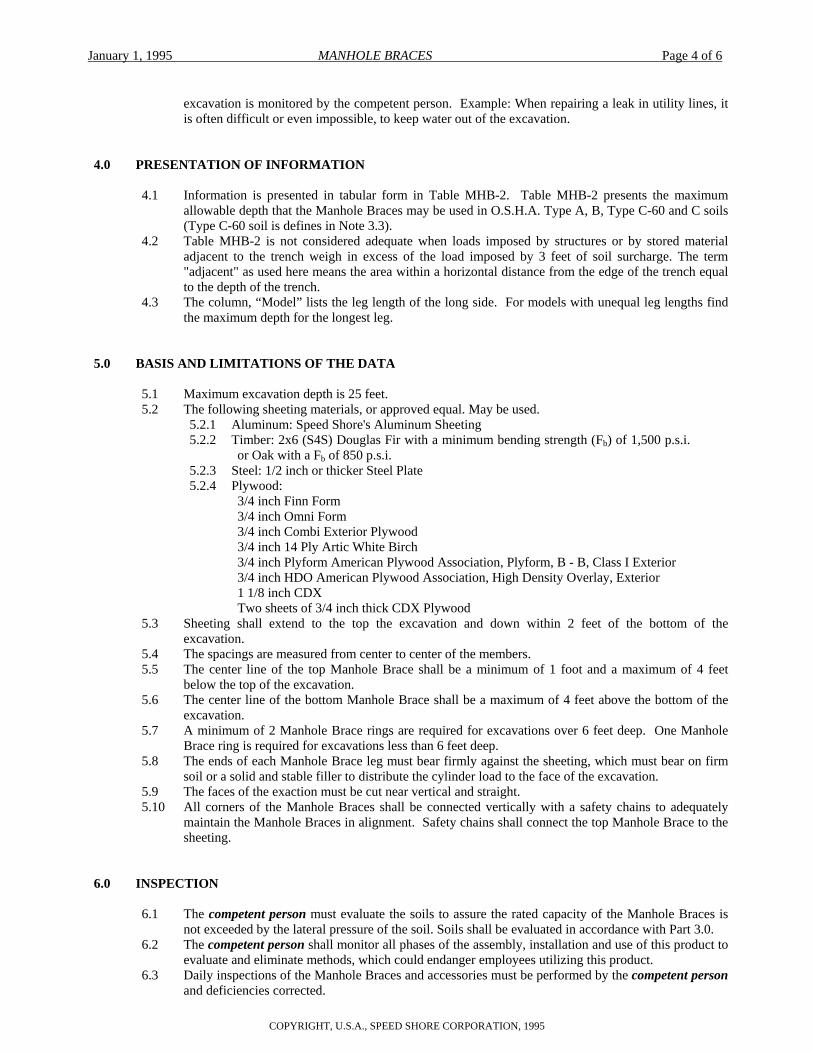
4.0 PRESENTATION OF INFORMATION
4.1 Information is presented in tabular form in Table MHB-2. Table MHB-2 presents the maximum allowable depth that the Manhole Braces may be used in O.S.H.A. Type A, B, Type C-60 and C soils (Type C-60 soil is defines in Note 3.3).
4.2 Table MHB-2 is not considered adequate when loads imposed by structures or by stored material adjacent to the trench weigh in excess of the load imposed by 3 feet of soil surcharge. The term "adjacent" as used here means the area within a horizontal distance from the edge of the trench equal to the depth of the trench.
4.3 The column, “Model” lists the leg length of the long side. For models with unequal leg lengths find the maximum depth for the longest leg.
5.0 BASIS AND LIMITATIONS OF THE DATA
5.1 Maximum excavation depth is 25 feet. 5.2 The following sheeting materials, or approved equal. May be used.
5.2.1 Aluminum: Speed Shore's Aluminum Sheeting 5.2.2 Timber: 2x6 (S4S) Douglas Fir with a minimum bending strength (Fb) of 1,500 p.s.i.
or Oak with a Fb of 850 p.s.i. 5.2.3 Steel: 1/2 inch or thicker Steel Plate 5.2.4 Plywood:
3/4 inch Finn Form 3/4 inch Omni Form 3/4 inch Combi Exterior Plywood 3/4 inch 14 Ply Artic White Birch 3/4 inch Plyform American Plywood Association, Plyform, B - B, Class I Exterior 3/4 inch HDO American Plywood Association, High Density Overlay, Exterior 1 1/8 inch CDX Two sheets of 3/4 inch thick CDX Plywood
5.3 Sheeting shall extend to the top the excavation and down within 2 feet of the bottom of the excavation.
5.4 The spacings are measured from center to center of the members. 5.5 The center line of the top Manhole Brace shall be a minimum of 1 foot and a maximum of 4 feet
below the top of the excavation. 5.6 The center line of the bottom Manhole Brace shall be a maximum of 4 feet above the bottom of the
excavation. 5.7 A minimum of 2 Manhole Brace rings are required for excavations over 6 feet deep. One Manhole
Brace ring is required for excavations less than 6 feet deep. 5.8 The ends of each Manhole Brace leg must bear firmly against the sheeting, which must bear on firm
soil or a solid and stable filler to distribute the cylinder load to the face of the excavation. 5.9 The faces of the exaction must be cut near vertical and straight. 5.10 All corners of the Manhole Braces shall be connected vertically with a safety chains to adequately
maintain the Manhole Braces in alignment. Safety chains shall connect the top Manhole Brace to the sheeting.
6.0 INSPECTION
6.1 The competent person must evaluate the soils to assure the rated capacity of the Manhole Braces is not exceeded by the lateral pressure of the soil. Soils shall be evaluated in accordance with Part 3.0.
6.2 The competent person shall monitor all phases of the assembly, installation and use of this product to evaluate and eliminate methods, which could endanger employees utilizing this product.
6.3 Daily inspections of the Manhole Braces and accessories must be performed by the competent person and deficiencies corrected.
January 1, 1995 MANHOLE BRACES Page 5 of 6
COPYRIGHT, U.S.A., SPEED SHORE CORPORATION, 1995
6.4 Inspections shall be conducted as necessary for hazards associated with water accumulation, changing soil conditions, or changing site weather conditions.
7.0 EXAMPLE TO ILLUSTRATE THE USE OF TABLE MHB-2:
Problem: Design a trench safety system using Speed Shore Manhole Braces system for a square shaft-type excavation with an opening 13 feet x 13 feet and 10 feet deep in C-60 soil (see note 3.3 for definition). Study table MHB-2 and read down column “Span.” Select a minimum-maximum range of 11 to 14 feet so that the Manhole Brace system retains additional stroke capability past the 13 feet dimension. Read left and find a 3 inch hydraulic cylinder size and model “3-MHB-6-11”. Read right under column C-60 and determine that the maximum depth for this model is 11 feet, therefore adequate for this job. Conclusion: Model “3-MHB-6-11” is selected. Install first Manhole Brace within 2 feet of the top of the shaft and the second Manhole Brace four feet below the top Manhole Brace. Note the bottom Manhole Brace will be four feet above the bottom of the excavation. Note 5.1 requires timber, plywood or equal sheeting. Model “3-MHB-8-11” will also shore the excavation.
January 1, 1995 MANHOLE BRACES Page 6 of 6
COPYRIGHT, U.S.A., SPEED SHORE CORPORATION, 1995
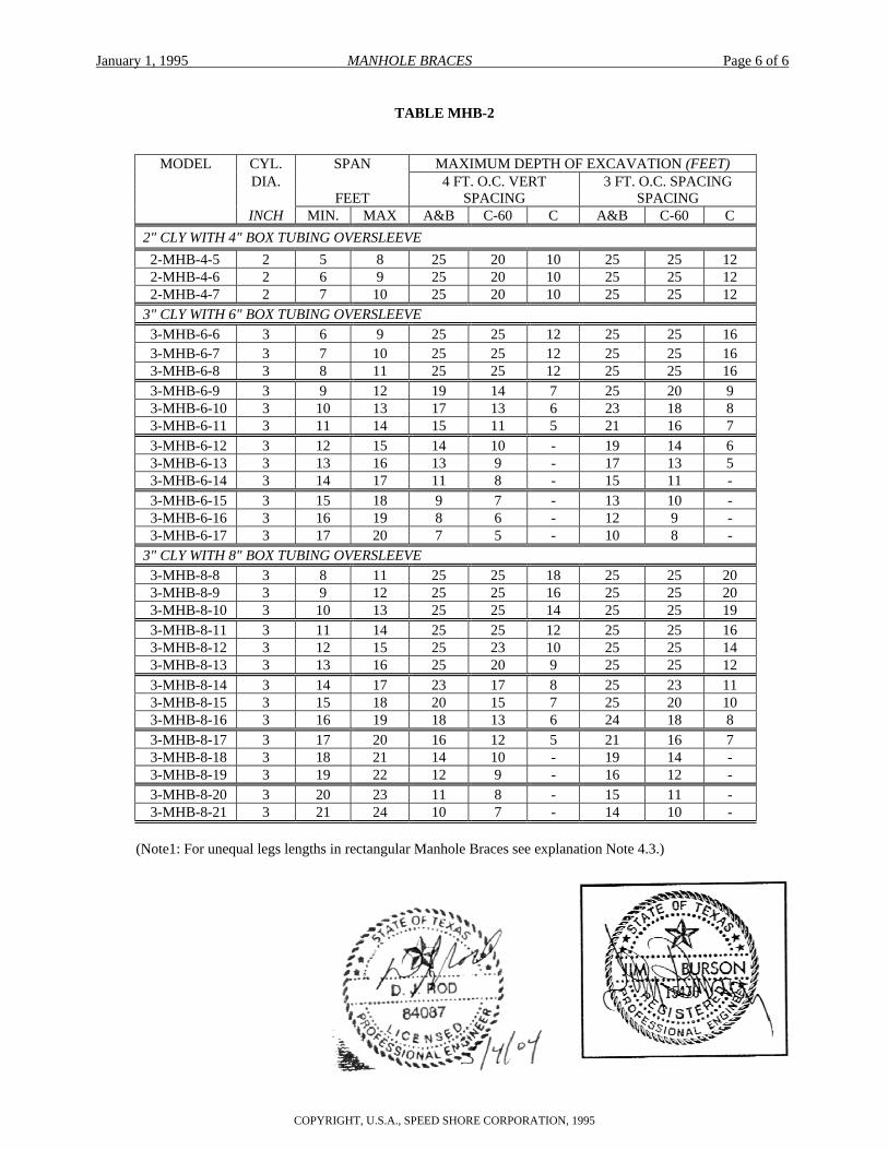
TABLE MHB-2
MODEL CYL. SPAN MAXIMUM DEPTH OF EXCAVATION (FEET) DIA. 4 FT. O.C. VERT 3 FT. O.C. SPACING FEET SPACING SPACING INCH MIN. MAX A&B C-60 C A&B C-60 C 2" CLY WITH 4" BOX TUBING OVERSLEEVE 2-MHB-4-5 2 5 8 25 20 10 25 25 12 2-MHB-4-6 2 6 9 25 20 10 25 25 12 2-MHB-4-7 2 7 10 25 20 10 25 25 12 3" CLY WITH 6" BOX TUBING OVERSLEEVE 3-MHB-6-6 3 6 9 25 25 12 25 25 16 3-MHB-6-7 3 7 10 25 25 12 25 25 16 3-MHB-6-8 3 8 11 25 25 12 25 25 16 3-MHB-6-9 3 9 12 19 14 7 25 20 9 3-MHB-6-10 3 10 13 17 13 6 23 18 8 3-MHB-6-11 3 11 14 15 11 5 21 16 7 3-MHB-6-12 3 12 15 14 10 - 19 14 6 3-MHB-6-13 3 13 16 13 9 - 17 13 5 3-MHB-6-14 3 14 17 11 8 - 15 11 - 3-MHB-6-15 3 15 18 9 7 - 13 10 - 3-MHB-6-16 3 16 19 8 6 - 12 9 - 3-MHB-6-17 3 17 20 7 5 - 10 8 - 3" CLY WITH 8" BOX TUBING OVERSLEEVE 3-MHB-8-8 3 8 11 25 25 18 25 25 20 3-MHB-8-9 3 9 12 25 25 16 25 25 20 3-MHB-8-10 3 10 13 25 25 14 25 25 19 3-MHB-8-11 3 11 14 25 25 12 25 25 16 3-MHB-8-12 3 12 15 25 23 10 25 25 14 3-MHB-8-13 3 13 16 25 20 9 25 25 12 3-MHB-8-14 3 14 17 23 17 8 25 23 11 3-MHB-8-15 3 15 18 20 15 7 25 20 10 3-MHB-8-16 3 16 19 18 13 6 24 18 8 3-MHB-8-17 3 17 20 16 12 5 21 16 7 3-MHB-8-18 3 18 21 14 10 - 19 14 - 3-MHB-8-19 3 19 22 12 9 - 16 12 - 3-MHB-8-20 3 20 23 11 8 - 15 11 - 3-MHB-8-21 3 21 24 10 7 - 14 10 -
(Note1: For unequal legs lengths in rectangular Manhole Braces see explanation Note 4.3.)