MANEUVERABLE VACUUM CLEANER FOR THE...
41
Maneuverable vacuum cleaner for the handicapped Item Type text; Thesis-Reproduction (electronic) Authors Eidelson, Arthur Fillip Publisher The University of Arizona. Rights Copyright © is held by the author. Digital access to this material is made possible by the University Libraries, University of Arizona. Further transmission, reproduction or presentation (such as public display or performance) of protected items is prohibited except with permission of the author. Download date 28/06/2018 06:07:03 Link to Item http://hdl.handle.net/10150/348398
Transcript of MANEUVERABLE VACUUM CLEANER FOR THE...

Maneuverable vacuum cleaner for the handicapped
Item Type text; Thesis-Reproduction (electronic)
Authors Eidelson, Arthur Fillip
Publisher The University of Arizona.
Rights Copyright © is held by the author. Digital access to this materialis made possible by the University Libraries, University of Arizona.Further transmission, reproduction or presentation (such aspublic display or performance) of protected items is prohibitedexcept with permission of the author.
Download date 28/06/2018 06:07:03
Link to Item http://hdl.handle.net/10150/348398

MANEUVERABLE VACUUM CLEANER FOR THE HANDICAPPED
byArthur Fillip Eidelson
A Thesis Submitted to the Faculty of theDEPARTMENT OF ELECTRICAL ENGINEERING
In Partial Fulfillment of the Requirements For. the Degree ofMASTER OF SCIENCE
In the Graduate CollegeTHE UNIVERSITY OF ARIZONA
1 9 7 8

STATEMENT BY AUTHOR
This thesis has been submitted in partial fulfillment of requirements for an advanced degree at The University of Arizona and is deposited in the University Library to be made available to borrowers under rules of the Library,
Brief quotations from this thesis are allowable without special permission, provided.that accurate acknowledgment of source is made, Requests for permission for extended quotation from or reproduction of this manuscript in whole or in part may be granted by the head of the major department or the Dean of the Graduate College when in his judgment the proposed use of the material is in the interests of scholarship. In all other instances, however, permission must be obtained from the author„
SIGNED:
APPROVAL BY THESIS DIRECTOR This thesis has been approved on the date shown below:
~ T I — j ~ T ~ li, STHEODORE L. WILLIAMS ' 0 Date
Associate Professor of Electrical Engineering

ACKNOWLEDGMENTS
The author wishes to thank Dr. Theodore L . Williams for his guidance and encouragement in writing this thesis; also Dr. Reginald L. Call for his critical comments.
iii

TABLE OF CONTENTS
PageLIST OF ILLUSTRATIONS . . . vABSTRACT . . . . . . . . . . . . . . viCHAPTER
1. INTRODUCTION ............. 12. MECHANICAL ASSEMBLY . . . . . . . . . . . . . . 4
Roving Platform . . . . . . . . . 4Motorized Wheel . . . . . . . . . . . . . . 4Turning Motor . . . . . . . . . . . . . . . 6Vacuum Cleaner . . . . . . . . . 8Chain and Belt Drive . . . . . . . . . . . . 8Miscellaneous . . . . . . . . . . . . . . . 11
3. SOLID STATE DEVICES . . . . . . . . . 14Unijunction Transistors . . . . . . . . . . 14Silicon Controlled Rectifiers . . . . . . . 16
4. ELECTRONIC CIRCUITRY . . . . . . . . . . . . . . 20UJT Oscillator Circuit . . . . . . . . . . . 20Phase Control of the Motorized Wheel . . . . 23
5. ELECTRICAL CONNECTIONS . . . . . . . . . . . . . 29/
6. EVALUATION OF THE MANEUVERABLE VACUUM CLEANER . 31SELECTED BIBLIOGRAPHY . . . . . . . . . . 33

LIST OF ILLUSTRATIONS
Figure Page2„1 Bottom view showing the physical design
of the roving platform . . . . . . . . . . . . 52.2 Illustration of the motorized wheel 72.3 Top view showing chain drive . . . . . . . . . 92.4 Illustration showing belt drive 102.5 Illustration showing the mechanical assembly
of the platform as viewed from the bottom . . 122.6 Illustration showing the mechanical assembly
of the platform as viewed from the top . . . 133.1 Ca)_ Junction diagram, (b) equivalent
circuit, (c) electrical symbol for the UJT . 153.2 Characteristics of the SCR: (a) junction
diagram, (b) transistor equivalent circuit,(cl electrical symbol . . . . . . . 17
3.3 Typical application for the SCR ......... 194.1 Power supply circuit for vacuum cleaner
and turning motor . . . . . . . . . . . . . . 214.2 UJT oscillator circuit used to achieve
phase control 224.3 Voltage across the capacitor and output
voltage as a function of time . . . . . . . . 244.4 Complete phase control circuit controlling
the motorized wheel ........ 254.5 Phase control firing of SCR #1 274.6 Phase control firing of SCR #2 285.1 Electrical diagram showing ribbon cable
interface between the control box and roving platform 30
y

ABSTRACT
The purpose of this work is to present a novel concept . in vacuum cleaner design- Through the use of a unique electrical circuit and physical design, control was maintained over a roving platform on which a vacuum cleaner was mounted.
Phase control is a method by which the speed of a motor may be made to vary. This method is normally used with alternating current motors but was developed and applied to a direct current motor. The motor in turn was used to drive a single wheel in both the forward and reverse directions while varying speed. Maneuverability over the roving platform was obtained through control of this single wheel. Left and right turning action was made available through the use of a second direct current motor.
The particular vacuum cleaner system described in this paper is directly applicable for use by the handicapped or other persons unable or unwilling to push a conventional cleaner.

CHAPTER 1
INTRODUCTION
The fictional robot has traditionally been a mobile device somewhat humanoid in appearance. However, while the humanoid robot has yet to make its appearance, robot devices are already, with us-
Robot traffic signals replace the human policeman waving his arms. Chores.are passed to robot washing machines and robot dishwashers. Telephones physically located miles apart“are connected through switching net-works handled completely by robots.
1Professor Meredith Thring of Queens Mary College has suggested that the minimal robot must include:
1. A method of self-propulsion and self-steering.2. Power systems and control systems for propulsion
and steering.3. A computer memory for storing instructions and
decision making; - , ’4 „ Various senses (e.g., sight, hearing, the ability
to sense position, and the ability to judge distance).
J. F . Young, Robotics (England: Redwood PressLimited, 1973), p. 4.
1

In terms of Thring'1 s four characteristics, the roving vacuum cleaner described in the later sections of this paper did not constitute a robot. Although the propulsion and control systems were robotic qualities, decision making was left entirely to the discretion of the operator. This resulted in the distinct advantage of low cost and good cdntrol as the operator's senses and thinking process were incorporated into direct action by the roving platform.
A floor and carpet cleaning robot has been built by 2Mr. Benjamin Skora. The adult-sized robot was 6 feet 8
inches tall and weighed 275 pounds. Power was derived from two 12 volt batteries normally found in an automobile. One battery was used to supply power to the electronics and the other to drive motors. Control of ambulation was achieved by telemetry and built in programs.
The kikora robot was too sophisticated for use by .. the layman and thus was impractical as a cleaning appliance for the American home. Other drawbacks included cost of construction and education of the operator in programming techniques.
The maneuverable vacuum cleaner described in this paper was designed to be low in cost and practical for use in the average home. The maneuverable vacuum system was
^Linda Folkard-Stengel, "AROK," Interface, Vol. X.(April, 1977), p. 38.

constructed on a circular frame. The frame stood on three- casters set in a triangular pattern. A motorized wheel was placed in the center of the triangle. Sitting on the circular frame was a vacuum cleaner and turning motor. The turning motor positioned the circular frame in either a clockwise or counterclockwise direction. Control of the frame was provided by a control box which was attached to the vacuum system via an umbilical cord. A single potentiometer moved the platform in the forward or reverse directions while varying speed. A slide switch moved the platform toward the left or right.

CHAPTER 2.
MECHANICAL ASSEMBLY
The fabrication of a maneuverable vacuum cleaner involved interfacing mechanical components with electrical circuitry. A unique physical design based on a triangular wheel structure provided stability and low construction N cost. Following is a description of the various components which made.up the physical design of the maneuverable vacuum cleaner. Figures are provided to identify the components and to illustrate mechanical linkages.
Roving Platform The roving platform was constructed of sheet metal
3/32 inches thick. It stood 6.5 inches off the ground via three caster wheels arranged in a triangular pattern. The diameter of the circular platform was 13 inches. Figure
- y-2.1 illustrates the physical design of the roving platform. As shown in Figure 2.1, a rubber center bumper and rubber bottom bumper were mounted in strategic locations to help prevent damage to furniture as the platform moved.
Motorized Wheel The motorized wheel consisted of a 4.5 inch rubber
tire wheel mounted in a swivel fork and gear driven by a
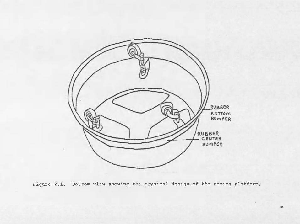
Figure 2.1. Bottom view showing the physical design of the roving platform.
U1

permanent magnetic field, DC reversible motor. The motor operated on either a 6 volt or 12 volt battery. The no load current was 2 amperes and the "stall current" was 8 amperes. The operating current had a value between 2 and 8 anperes depending on the mechanical load of the motor, and the voltage used. The approximate "no load" speed was 120 RPM on 12 volts and 65 RPM on 6 volts. Figure 2.2 illus- trates the motorized wheel.
Turning Motor The motorized wheel was driven in either the clock
wise or counterclockwise direction via chain drive by a permanent magnetic field, DC electric reversible motor.The motor operated on either 12 volts or 6 volts. The turning motor contained an internal gearhead and had a . speed of 5 RPM at 6 volts and 10 RPM at 12 volts. Full load current was 50 milliamperes. Running torque was in excess of 40 ounce-inches at either voltage. The motor was two inches in diameter and 3-1/8 inches long excluding the shaft. The turning motor was also used to position one of the three casters left or right via a 1/5 inch pitch 15 inch long timing belt. The position of the caster was kept parallel with the motorized wheel and was used to steer the roving platform left or right.

Wheel motor
Figure 2.2. Illustration of the motorized wheel.

Vacuum Cleaner The vacuum cleaner incorporated into.the roving
platform was a modified 12 volt DC automobile vacuum • cleaner. Modifications involved removing a jack from which the cleaner derived power. The jack was designed to be inserted into an automobile's cigarette lighter from which 12 volts could be obtained from the automobile's battery. The vacuum cleaner's dimensions were 11-1/2 inches long with a 4 inch on a side square base.
Chain and Belt Drive sTwo sprockets, one from the rear wheel and one from
the. chainwheel of a 24 inch bicycle had been incorporated into the roving platform. The rear wheel sprocket was mounted on the turning motor described on page 6. The chainwheel sprocket was used with a ball bearing bicycle mount and was located on the motorized wheel described on pages 4 and 6. The two sprockets in conjunction with a chain were used to transfer motion from the turning motor to the motorized wheel. yFigure 2.3 illustrates the chain drive assembly.
A 1/5 inch pitch timing belt in conjunction with two timing gears was used to position one caster in paral- = lei with the motorized wheel. The caster aided in steering the roving platform. Figure 2.4 illustrates the timing belt assembly.

9
Figure 2.3, Top view showing chain drive.

Timinggear

Miscellaneous Two normally closed push button limit switches were
held by a sheet metal brace which was located on the underside of the platform. If the motorized wheel turned more than 90 degrees, the wheel pressed against a limit switch. The switch would open and voltage to the turning motor would be terminated. The wheel could however turn in the opposite direction before another limit switch would be engaged. Upon the successful interfacing of the various components described on the previous pages, the mechanical assembly ''of the maneuverable vacuum- cleaner was completed. Remaining was the design and debugging of the electrical circuitry which would be used to control the platform. Figure 2.5 illustrates", the overall construction of the roving vacuum cleaner. Figure 2.6 illustrates the same platform as viewed ...from the top.

Turningmotor
Limitswitch I
; ;rt '/ W * <73
Rubberbottombumper
Vacuum
Limitswitch
Motorized • wheel
Casterwheel
Figure 2.5. Illustration showing the mechanical assembly of the platform as viewed from the bottom.
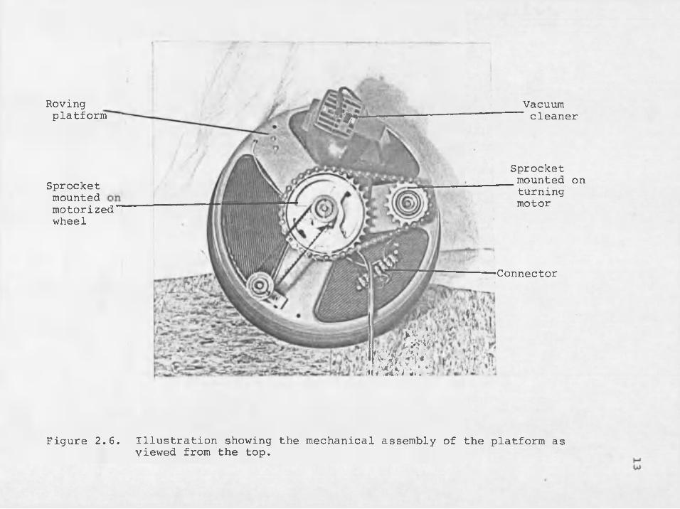
Roving platform
Sprocket mounted motorized wheel
>Vacuumcleaner
Sprocket mounted onturningmotor
—Connector
miFigure 2.6. Illustration showing the mechanical assembly of the platform as
viewed from the top.

CHAPTER 3
SOLID STATE DEVICES
The maneuverable vacuum cleaner utilized several solid , state devices other than transistors to control movement of the roving platform. Since these devices may not be familiar to the reader,.a short review follows.
Unijunction TransistorsUnlike the transistor which is a signal device, the
UJT (unijunction transistor) is a breakdown device. Figure3.1 shows the junction diagram, equivalent circuit, and electrical circuit for the UJT.
The homogenous N material shown in Figure 3.la has < a characteristic resistance of 4000 to 1000 ohms when measured between the bases. The resistance is denoted as Rbb in Figure 3.1b. When forward bias is applied to the emit- . ter of the UJT with respect to Bl, holes are injected into the N material. This results in a sharp increase in conductivity from B2 to Bl.
There are several methods of fabricating UJT devices. Whether alloying or impurity diffusion is used, the UJT is stable against power supply changes. This is due to the fact that as the power supply voltage moves up
14

E m m e R
BA5 6 A
N
6Ase n.
p i n a
1 a a
Piiu a.PiiJ 3
oflsecmrrreRoA'SC ^
EfniTTeR
Hooo- looo o hrnsA&OUX 10o ohf LS'Pol /ovch jfoci*/ircL
Figure 3.1. (a) Junction diagram, (b) equivalent circuit, (c) electrical symbol

or down, the critical voltage needed for breakdown of the device moves up or down accordingly. The UJT is often used to generate a source of pulses. The pulses are stable against power supply and temperature changes. The UJT specifications for the device incorporated within the roving platform control box may be found in the Motorola Solid State Semiconductor Data Library.
Silicon Controlled RectifiersThe SCR (silicon controlled rectifier) is a device
that conducts in only one direction. But unlike a diode, the SCR may be "fired" by placing a certain amount of voltage on the gate. Once the SCR is.., turned, "on," it can only be turned "off" when its power supply voltage becomes 0 volts or holding current for the device drops below a certain specified value.
The SCR is temperature sensitive. It is possible for thermal carriers to create false triggering.
The SCR is a four layered device as shown in Figure 3.2a. The transistor equivalent of the SCR is shown in Figure 3.2b. Figure 3.2c shows the electrical symbol for the SCR.
The SCR is used typically with an AC source. The , SCR is placed in series with a load and is gated by a timing circuit. Normally the SCR is delayed in firing until some point in the half cycle is reached as shown in

17
fl/vooe
PNP A jK
n p n
CATHODE
G a t e
O D E(%)
Figure 3.2, Characteristics of the SCR: (a) junctiondiagram, (b) transistor equivalent circuit, (c) electrical symbol,

18Figure 3.3. Specifications for the SCR used within the roving platform control box may be found in the Motorola Solid State Semiconductor Data Library.

19
3
ScR THIS PdftT OF Ac cyccf
+ V0CT
Figure 3,3. Typical application for the SCR.
CHAPTER 4
ELECTRONIC CIRCUITRY
The roving vacuum cleaner utilized a 12 volt and 25volt direct curent power supply to operate the vacuumcleaner and turning motor respectively. The two voltages were obtained through the full wave rectification and filtering of an alternating current produced from the output of step down transformers. Figure 4.1 shows the power supply circuit. In addition to these two voltages, a 25 volt alternating current produced from the output of a third step down transformer was used to help achieve phase control over the motorized wheel. All three power supply circuitswere housed in a control box and connected to the rovingcleaner through a seven conductor ribbon cable..
UJT Oscillator Circuit Figure 4.2 illustrates an UJT oscillator circuit
which makes up a large part of the electronics used to achieve phase control over the motorized wheel. A charging circuit was formed with a 0.1 yF. capacitor and 100,000 ohm potentiometer. . When battery voltage is first applied, the capacitor has 0 volts across its leads. The emitter of the UJT is reverse biased at the onset because the capacitor
20

Figure 4.
Fose
FULL w/weBAIDoeA E c T X F X E R
■SooAte
1700 vourTO VAcuv/ri
moroRSu/ITCH
L. Power supply circuit for vacuum cleaner and turning motor,

22
+ V C C
Figure 4.2, UJT oscillator circuit used to achieve phase control.

23voltage is less than the voltage needed to "fire" the UJT. The capacitor dumps its charge through the UJT and 47 ohm resistor when the charging capacitor has a voltage drop that exceeds the standoff voltage of the UJT. This voltage drop across the capacitor keeps the UJT "off." Meanwhile,, the capacitor begins to charge again. Each time the capacitor voltage exceeds the standoff voltage of the UJT, conduction occurs, placing an output pulse across the load. Figure 4.3 illustrates the voltage across the capacitor and output voltage as a function of time. Note that the minimum value of the capacitor voltage is called the valley voltage. At the valley voltage, the injection level of current from the emitter of the UJT has reduced the resistance of the bulk between the two bases of the UJT to about 100 ohms.
Phase Control of the ■Motorized Wheel As shown in Figure 4.4, an identical set of timing
circuits were used to "fire" one of two SCR's. Timing was provided by a 0.1 pF. capacitor and variable dual potentiometer. The potentiometer consisted of the two sections labeled A and B. The potentiometer was wired so that.as an A section of resistance increased, the B resistance section decreased by a corresponding amount. Suppose that the motorized wheel was "off." Neither SCR #1 nor #2 was "fired." The resistance of sections A and; B of the

V v
OUTPUTfVL.SE
V v 5 V f l U E ' j V O L T f ) 5 e
Vc V O L T A S E A c A O S S C A f A C I T o K
Figure 4.3. Voltage across the capacitor and output voltage as a function of time.

/ \ lioao^oICO
Figure 4.4. Complete phase control circuit controlling the motorized wheel.NJin

26potentiometer prevented either 0.1 liF. capacitor from charging to a high enough voltage that would "fire" either UJT. Now suppose the control potentiometer is set to a new value of resistance. Let the resistance of section 1A decrease and the resistance of section IB increase. The charging circuit involving the 0.1 yF. capacitor and 1A section of resistance "fired" the UJT and SCR #1 turned "on." This resulted in the motorized wheel turning in the forward direction. The greater the amount of resistance of section IB, the faster the motorized wheel turned in the forward direction. The fastest speed was obtained when the UJT was made to "fire" on the positive half cycles of the AC waveform. As the control potentiometer is turned in the opposite direction, the forward speed of the motorized wheel decreased as the resistance of the potentiometer section labeled 1A increased. When the resistance of section IB was about equal to the resistance of section 1A, the motorized wheel turned "off." As the potentiometer was further turned, the resistance of section IB became increasingly less than the resistance" of section 1A. SCR #2 "fired," and the motorized wheel turned in the reverse direction. A further decrease in section IB's resistance resulted in a faster reverse speed for the motorized wheel. Figures 4,5 ;and 4.6 illustrate phase control firing of SCR #1 and SCR #2 respectively.

VOLTA G*€R65P0<V.S5 OF LO ad \;o lTAG-e To 5 c k # 1 fifc'rivi; G A T c o
Figure 4,5. Phase control firing of SCR #1. K>'sj

VO LT4G-ERe5f<i<vse of loqvsea, # a 6ez/V(? s-ftteo
Figure 4.6. Phase control firing of SCR #2. N)00

CHAPTER 5
ELECTRICAL CONNECTIONS
The roving vacuum cleaner was controlled from a remote location via a 20 foot long ribbon cable. .The cable connected the control potentiometer and slide switch located on the control box to the roving platform which contained the vacuum cleaner, turning motor, and motorized wheel. Figure 5.1 shows the electrical diagram for the roving platform.
29.

TOV«<vO>n<U.«*VCA
PHMSc
w«*i
"CDCD€)-0>
Ci'lfOrrj* OuTre«j toirte
dy(D-CDCD- •
<D
CDCtot£*Kit, |urrew IfclTC*
RED
+UvotTi &C
BRoWfJ6kAVWAlTC
e ckBLUEpotnc
/CoJWcctor £ T K i p *-C>CfiT6t> Ok) AjDVIWG PLQTfor rr\\W CftjtH BUTTOk)twitchTO TUAWIWg mo to ft(Aeo iviftr)
\ bcfVT* gunow Tvrrcw
CokmkoL foTtWTlomFrti AMD RElATfG CIAcvITAy
TlLSVevts cC
rr- 5-vU,DC
SXTDES W IT C H Poft LEFT AMD RIGHT movemeMTi
C o n t r o l B o x
Figure 5.1. Electrical diagram showing ribbon cable inter face between the control box and roving platform.

CHAPTER 6
EVALUATION OF THE MANEUVERABLE VACUUM CLEANER
The maneuverable vacuum cleaner performed the functions for which it was designed. An operator may sit several feet from the platform while controlling its movement by pushing a slide switch and turning a control knob.If the maneuverable vacuum cleaner should get stuck against an obstruction such as a wall, the motorized wheel would attempt to turn. No damage would result to the roving platform or control circuitry. Several areas exist which must be studied further before the maneuverable vacuum cleaner may be taken out of the laboratory and into the home.
First, a more powerful vacuum cleaner is desirable. If a suction could be created over a larger area, there would be less wasted movement of the platform. A faster cleaning time would result. At the present stage of design, the maneuverable vacuum cleaner utilizes a direct current vacuum cleaner. An alternating current cleaner would be more powerful compared to its direct current counterpart.
Second, weight distribution was not spread out evenly over the roving platform. Unequal amounts of drag
31

were supplied to each caster. This resulted in more frequent course corrections since the platform gradually deviates from a straight path.
Finally, tests should be performed using handi- • capped persons as operators. This would determine the extent to which the design of the platform and control box must be modified.

SELECTED BIBLIOGRAPHY
Folkard-Stengel, Linda. "AROK," Interface, Vol. 2 (April 1977), p. 38.
Hollis, R. "A Mobile Cognitive Robot, 11 Byte, Vol. 2 (June 1977), pp. 30-45.
Loofbourrow, T. "A Computer Controlled Robot," Interface, Vol. 2 (April 1977), pp. 18-30.
Streetman, B. G. Solid State Electronic Devices. Englewood Cliffs, N. J.: Prentice-Hall, Inc., 1972,
Young, J. F. Robotics. England: Redwood Press Limited, 1973.
33

.