mandibular overdenture (2).pdf
103
Implant assisted mandibular overdenture
-
Upload
ibrahim-ahmed-dahab -
Category
Documents
-
view
28 -
download
1
Transcript of mandibular overdenture (2).pdf

7/21/2019 mandibular overdenture (2).pdf
http://slidepdf.com/reader/full/mandibular-overdenture-2pdf 1/103
Implant assisted
mandibular overdenture

7/21/2019 mandibular overdenture (2).pdf
http://slidepdf.com/reader/full/mandibular-overdenture-2pdf 2/103
mandibular overdenture
7/21/2019 mandibular overdenture (2).pdf
http://slidepdf.com/reader/full/mandibular-overdenture-2pdf 3/103
Adv. Of mandibular over denture
versus conventional complete
denture

7/21/2019 mandibular overdenture (2).pdf
http://slidepdf.com/reader/full/mandibular-overdenture-2pdf 4/103
Improved
esthetics
speech
prosthesis
support
prosthesis
retention
occlusal
efficiency
chewing
efficiency
occlusion
stability

7/21/2019 mandibular overdenture (2).pdf
http://slidepdf.com/reader/full/mandibular-overdenture-2pdf 5/103
n a stu y y wa et a ., implant overdenture (IOD)
patients were able to chew
different types of foodsignificantly better than patients
with complete dentures (CDs).
(Data from Awad MA, Lund JP,
Dufresne E, et al: Comparing theefficacy of mandibular implant-
retained overdentures and
conventional dentures among
middle-aged edentulous patients: satisfaction and
functional assessment,

7/21/2019 mandibular overdenture (2).pdf
http://slidepdf.com/reader/full/mandibular-overdenture-2pdf 6/103
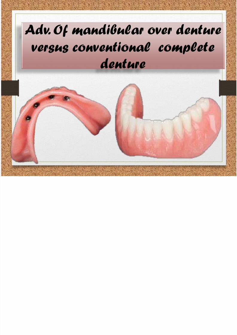
Adv. Of over denture versus the
fixed restoration Fixed Prosthesis
7/21/2019 mandibular overdenture (2).pdf
http://slidepdf.com/reader/full/mandibular-overdenture-2pdf 7/103
bonegrafting
specific implant placement
Fewer implants(RP-5)
Lower cost andlaboratory cost(RP-5)
Reduced stress
Hygiene
Improved
periimplant probing Improvedesthetics
Easyrepair
Stress
relief
attachment

7/21/2019 mandibular overdenture (2).pdf
http://slidepdf.com/reader/full/mandibular-overdenture-2pdf 8/103
Philosophy for Implants
in the
Edentulous Mandible
7/21/2019 mandibular overdenture (2).pdf
http://slidepdf.com/reader/full/mandibular-overdenture-2pdf 9/103
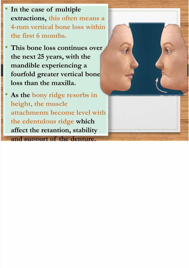
• In the case of multiple
extractions, this often means a
4-mm vertical bone loss within
the first 6 months.
• This bone loss continues over
the next 25 years, with the
mandible experiencing afourfold greater vertical bone
loss than the maxilla.
• As the bony ridge resorbs in
height, the muscle
attachments become level with
the edentulous ridge which
affect the retantion, stabilityand su ort of the denture.

7/21/2019 mandibular overdenture (2).pdf
http://slidepdf.com/reader/full/mandibular-overdenture-2pdf 10/103
• To the contrary, the anterior bone
under an overdenture may resorb as
little as 0.6 mm vertically over 5
years, and long-term resorption
may remain at less than 0.05 mm
per year.
• the dental professional should
educate the patient about the
bone loss process after tooth loss.
In addition, the patient should be
made aware the bone loss process can
be arrested by a dental implant.
• dental implants to maintain

7/21/2019 mandibular overdenture (2).pdf
http://slidepdf.com/reader/full/mandibular-overdenture-2pdf 11/103
Classification of
Prosthesis Movement
PM)

7/21/2019 mandibular overdenture (2).pdf
http://slidepdf.com/reader/full/mandibular-overdenture-2pdf 12/103
• An overdenture is by definition removable, but
in function or parafunction, the prosthesis may
not move.
• If the prosthesis does not have movement
during function, it is designated PM-0 and
requires implant support similar to a fixed prosthesis.
• A prosthesis with a hinge motion is PM-2, and
a prosthesis with an apical and hinge motion isPM-3.
• A PM-4 allows movement in four directions,
and a PM-6 has ranges of PM in all directions.

7/21/2019 mandibular overdenture (2).pdf
http://slidepdf.com/reader/full/mandibular-overdenture-2pdf 13/103
Implant site
selection

7/21/2019 mandibular overdenture (2).pdf
http://slidepdf.com/reader/full/mandibular-overdenture-2pdf 14/103

7/21/2019 mandibular overdenture (2).pdf
http://slidepdf.com/reader/full/mandibular-overdenture-2pdf 15/103
• Anatomical reasons:
more bone anterior increase thelength and width of the
implant…..increase the implantstability.
7/21/2019 mandibular overdenture (2).pdf
http://slidepdf.com/reader/full/mandibular-overdenture-2pdf 16/103
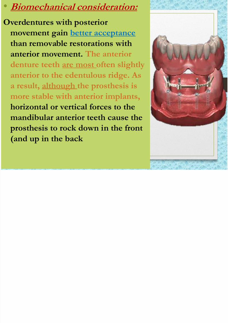
• Biomechanical consideration:
Overdentures with posterior
movement gain better acceptance
than removable restorations withanterior movement. The anterior
denture teeth are most often slightly
anterior to the edentulous ridge. As
a result, although the prosthesis is
more stable with anterior implants,
horizontal or vertical forces to the
mandibular anterior teeth cause the prosthesis to rock down in the front
(and up in the back
7/21/2019 mandibular overdenture (2).pdf
http://slidepdf.com/reader/full/mandibular-overdenture-2pdf 17/103
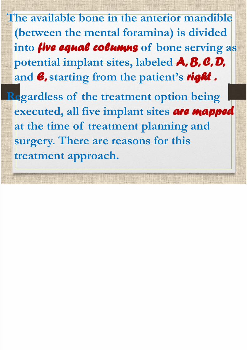
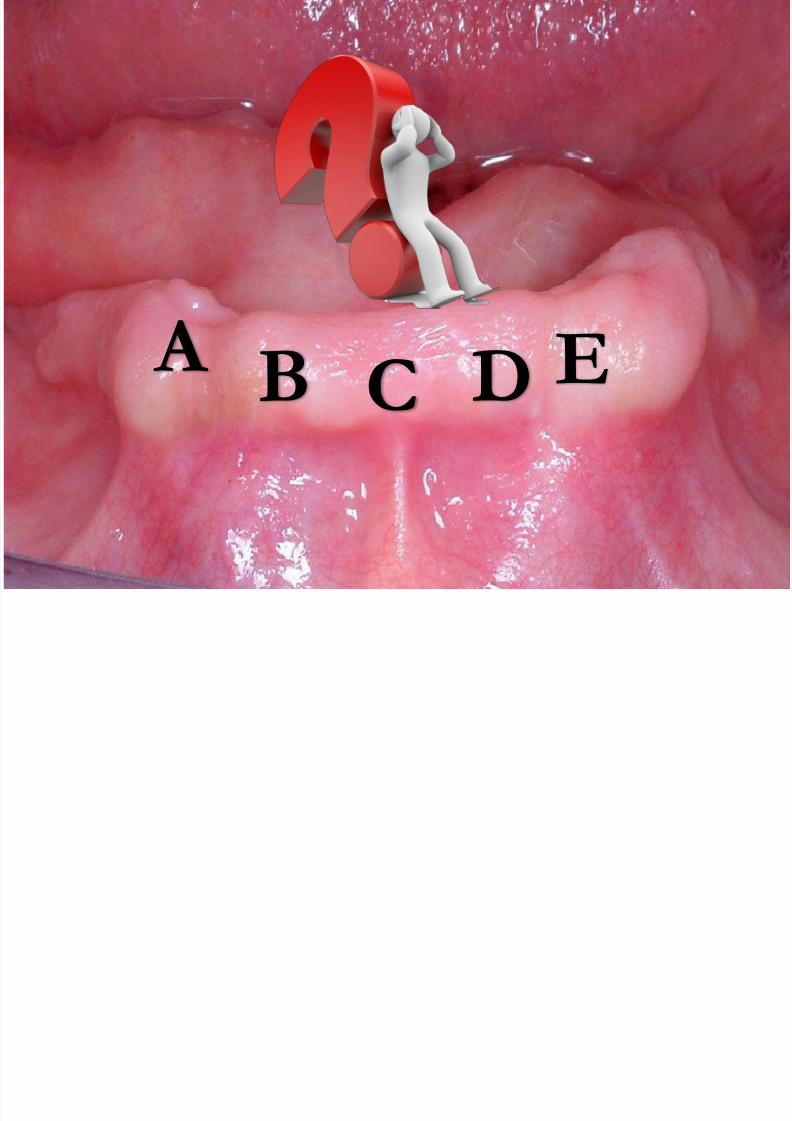
The available bone in the anterior mandible
(between the mental foramina) is divided
intofive equal columns
of bone serving as potential implant sites, labeled A, B, C, D,
and E, starting from the patient’s right .
Regardless of the treatment option being
executed, all five implant sitesare mapped
at the time of treatment planning andsurgery. There are reasons for this
treatment approach.
7/21/2019 mandibular overdenture (2).pdf
http://slidepdf.com/reader/full/mandibular-overdenture-2pdf 18/103
A
B C DE

7/21/2019 mandibular overdenture (2).pdf
http://slidepdf.com/reader/full/mandibular-overdenture-2pdf 19/103
Give the patient the
chance tochange histreatment
plan.
A patient maydesire a
completelyimplant-
supportedrestoration (e.g.,RP-4 or FP) but
cannot afford thetreatment all at
once.
If an implantcomplicationoccurs, the
preselectedoption sites permit
repeatablecorrective
procedures.
• Th dib l d t i t least 12 mm
7/21/2019 mandibular overdenture (2).pdf
http://slidepdf.com/reader/full/mandibular-overdenture-2pdf 20/103
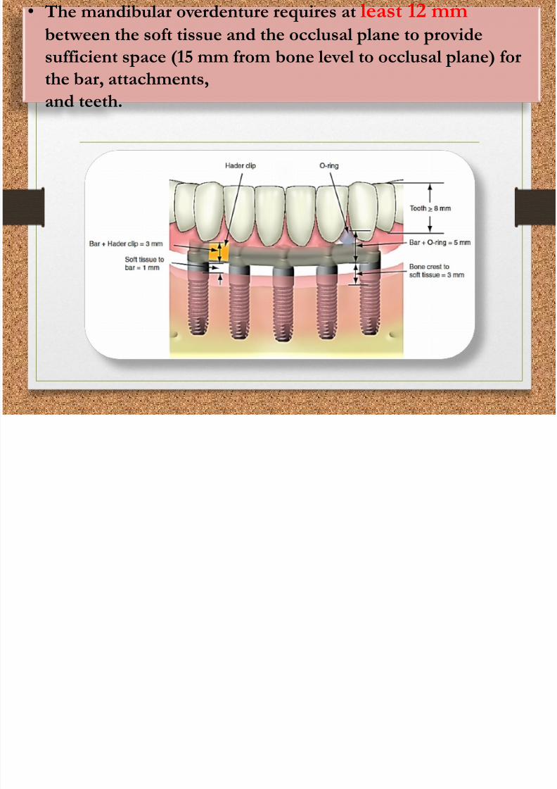
• The mandibular overdenture requires at least 12 mmbetween the soft tissue and the occlusal plane to provide
sufficient space (15 mm from bone level to occlusal plane) for
the bar, attachments,
and teeth.

7/21/2019 mandibular overdenture (2).pdf
http://slidepdf.com/reader/full/mandibular-overdenture-2pdf 21/103
7/21/2019 mandibular overdenture (2).pdf
http://slidepdf.com/reader/full/mandibular-overdenture-2pdf 22/103
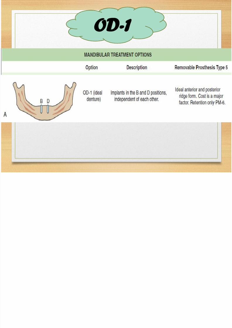
OD-1

7/21/2019 mandibular overdenture (2).pdf
http://slidepdf.com/reader/full/mandibular-overdenture-2pdf 23/103
Patient
selectioncriteria for:
OD-1
Opposinga maxillary
fulldenture
Anatomicalconditions are
good to excellent(division A or Banterior and
posterior bone
Additionalimplants willbe inserted within 3
years
Cost is the primary
factor
Edentulousridge not square with a tapered
dentate arch
form
Posteriorridge form isan inverted U
shape
Patient’s needsand desires are
minimal,
primarily relatedto lack of prosthesisretention

7/21/2019 mandibular overdenture (2).pdf
http://slidepdf.com/reader/full/mandibular-overdenture-2pdf 24/103
B D
7/21/2019 mandibular overdenture (2).pdf
http://slidepdf.com/reader/full/mandibular-overdenture-2pdf 25/103
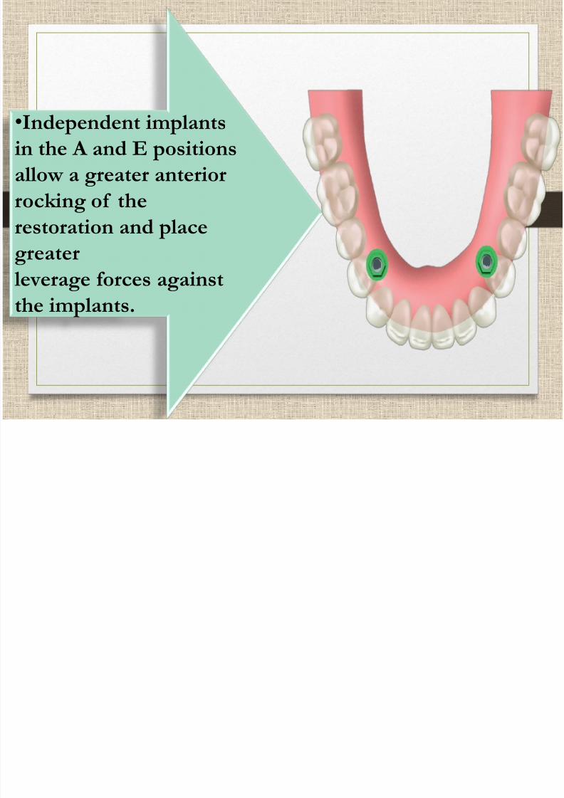
•Independent implants
in the A and E positions
allow a greater anterior
rocking of therestoration and place
greater
leverage forces against
the implants.

7/21/2019 mandibular overdenture (2).pdf
http://slidepdf.com/reader/full/mandibular-overdenture-2pdf 26/103
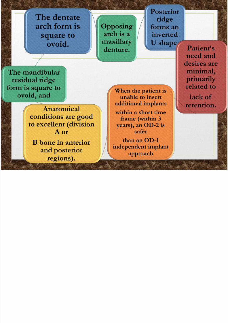
OD-2D-2

7/21/2019 mandibular overdenture (2).pdf
http://slidepdf.com/reader/full/mandibular-overdenture-2pdf 27/103
Patient selection
criteria for: OD-2
7/21/2019 mandibular overdenture (2).pdf
http://slidepdf.com/reader/full/mandibular-overdenture-2pdf 28/103
Opposingarch is a
maxillarydenture.
Posteriorridge
forms aninverted
U shape.Patient’sneed and
desires areminimal,
primarilyrelated to
lack ofretention.
When the patient isunable to insert
additional implants
within a short time
frame (within 3 years), an OD-2 issafer
than an OD-1independent implant
approach
Anatomical
conditions are goodto excellent (division A or
B bone in anteriorand posterior
regions).
The mandibular
residual ridgeform is square to
ovoid, and
The dentatearch form is
square toovoid.

7/21/2019 mandibular overdenture (2).pdf
http://slidepdf.com/reader/full/mandibular-overdenture-2pdf 29/103
implants in the B and D positions,and a bar joins the implants.
Attachments such as an O-ring ( A)
or a Hader
clip ( B), which allow movementof the prosthesis, can be added
to
the bar. The attachments are placed
at the same height at equal
distances off the midline and
parallel to each other.

7/21/2019 mandibular overdenture (2).pdf
http://slidepdf.com/reader/full/mandibular-overdenture-2pdf 30/103
Bar splinting the A andE positions will flex five
times more than a bar
connecting implants inthe B and D positions.
As a consequence,
screw loosening risk isincreased

7/21/2019 mandibular overdenture (2).pdf
http://slidepdf.com/reader/full/mandibular-overdenture-2pdf 31/103
The connecting bar between
implants B and D
should not be cantilevered to the
distal.
The Hader clips in the prosthesis do not allow
prosthesis movement.
Hence, this is a
PM-0 implant overdentureand will cause repeated
biomechanical
complications.
I l i A d E i i

7/21/2019 mandibular overdenture (2).pdf
http://slidepdf.com/reader/full/mandibular-overdenture-2pdf 32/103
Implants in A and E positionsnever be splinted
Implants joined with straight bar are
lingual to ridge:
• Difficulty with speech
• Anterior tipping of overdenture
• Five times greater bar flexure than B
and D positions.
Implants are joined with anterior curved bar.
• Greater bar flexibility (nine times the
B and D positions)
• Increased screw loosening
• Increased moment forces on anterior
aspect of prosthesis

7/21/2019 mandibular overdenture (2).pdf
http://slidepdf.com/reader/full/mandibular-overdenture-2pdf 33/103
Splinted Implants in the A
and E Positions lead to:
Implants joined
with straight bar
are lingual to
ridge result in
Difficulty with
speech andanterior tipping
of the denture

7/21/2019 mandibular overdenture (2).pdf
http://slidepdf.com/reader/full/mandibular-overdenture-2pdf 34/103
When O-rings are
used for OD-2, theattachments
are placed parallel
to each other andat the same
occlusal
height.

7/21/2019 mandibular overdenture (2).pdf
http://slidepdf.com/reader/full/mandibular-overdenture-2pdf 35/103
OD-3
7/21/2019 mandibular overdenture (2).pdf
http://slidepdf.com/reader/full/mandibular-overdenture-2pdf 36/103
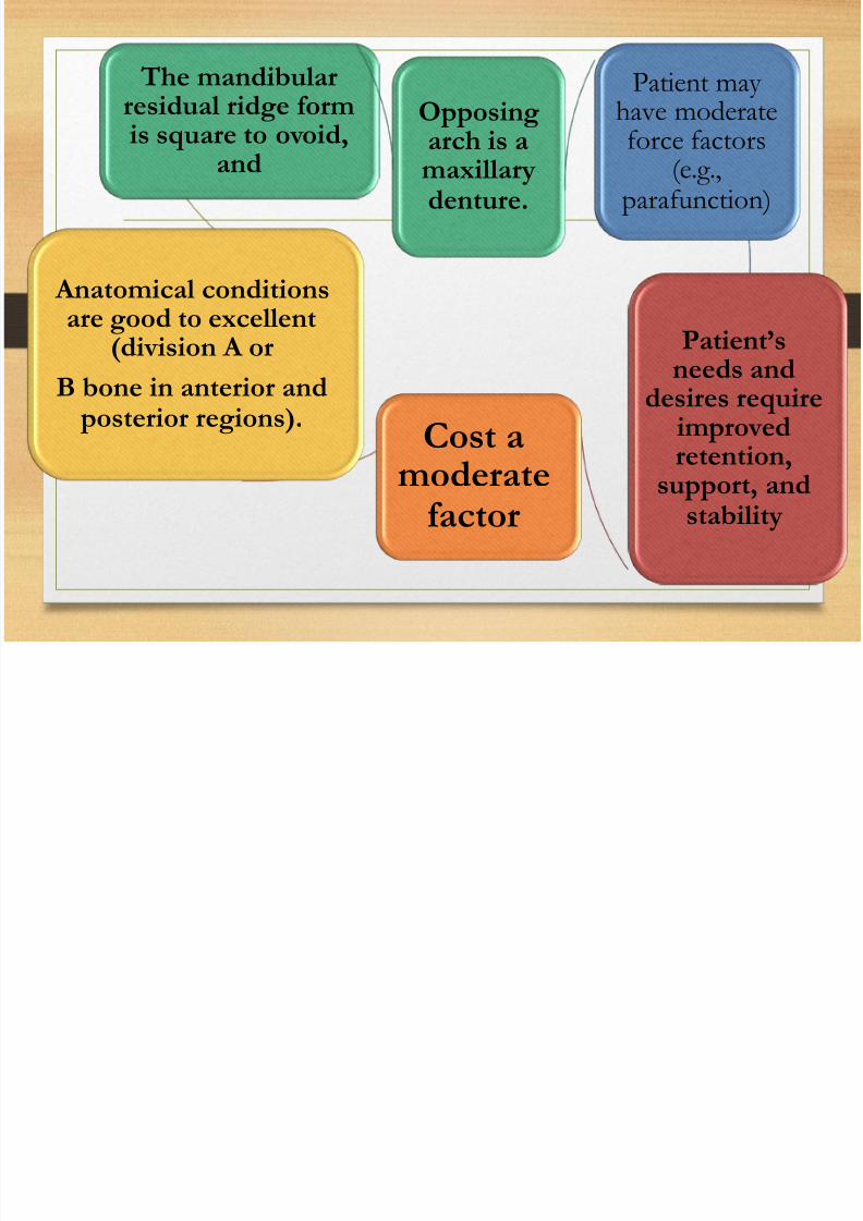
Opposingarch is amaxillarydenture.
Patient mayhave moderateforce factors
(e.g.,parafunction)
Patient’sneeds and
desires requireimproved
retention,support, and
stability
Cost amoderate
factor
Anatomical conditionsare good to excellent
(division A or
B bone in anterior and posterior regions).
The mandibularresidual ridge formis square to ovoid,
and

7/21/2019 mandibular overdenture (2).pdf
http://slidepdf.com/reader/full/mandibular-overdenture-2pdf 37/103
Advantages of Splinted A, C,
and E Implants
• Less screw loosening
• Less metal flexure
• Less stress to each implant compared with Aand E implants
• More implants Greater surface area
•
Less prosthesis movement• One implant failure still provides adequate
abutment support

7/21/2019 mandibular overdenture (2).pdf
http://slidepdf.com/reader/full/mandibular-overdenture-2pdf 38/103
The connecting bar between
implants in A, C and E
positions
The attachmentsshould be positioned
to allow movement of
the distal section of the prosthesis.(o-ring is
recommended)

7/21/2019 mandibular overdenture (2).pdf
http://slidepdf.com/reader/full/mandibular-overdenture-2pdf 39/103
OD-4
Patient’s

7/21/2019 mandibular overdenture (2).pdf
http://slidepdf.com/reader/full/mandibular-overdenture-2pdf 40/103
Opposingnaturalteeth
needs anddesiresrequire
improved
retention,support,
andstability
Increasethe CHSUnfavorable
force factors(parafunction, age, crown
height space>15 mm)
C – h bone volume
Patient selectioncriteria for:
OD-4

7/21/2019 mandibular overdenture (2).pdf
http://slidepdf.com/reader/full/mandibular-overdenture-2pdf 41/103
OD-4
four implants are
placed in the A, B, D,
and E positions. The
implants providesufficient support for a
distal
cantilever.
7/21/2019 mandibular overdenture (2).pdf
http://slidepdf.com/reader/full/mandibular-overdenture-2pdf 42/103
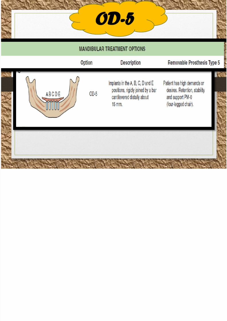
OD-5
Patient’s

7/21/2019 mandibular overdenture (2).pdf
http://slidepdf.com/reader/full/mandibular-overdenture-2pdf 43/103
Opposingnaturalteeth
needs anddesiresrequire
improved
retention,support,
andstability
Increase theCHS
Unfavorable
force factors(parafunction, age, crown
height space
>15 mm)
C – h bone volume
Patient selectioncriteria for:
OD-5

7/21/2019 mandibular overdenture (2).pdf
http://slidepdf.com/reader/full/mandibular-overdenture-2pdf 44/103
OD-5implants are placed
in the A, B, C, D, and
E positions. A barsplints the implants
together
and is distally
cantilevered. Thelength of the
cantilever depends
onthe anteroposterior
distance and the force
factors.

7/21/2019 mandibular overdenture (2).pdf
http://slidepdf.com/reader/full/mandibular-overdenture-2pdf 45/103
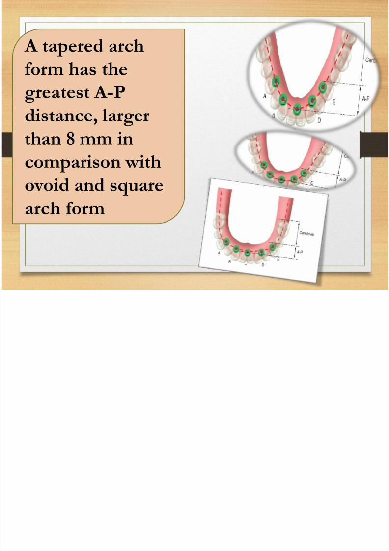
A-P spread rule for cantilever
A-P spread
It is the distance
from the middle ofthe most anterior
abutment to the
distal aspect of themost posterior
abutment.
7/21/2019 mandibular overdenture (2).pdf
http://slidepdf.com/reader/full/mandibular-overdenture-2pdf 46/103
A tapered arch
form has thegreatest A-P
distance, larger
than 8 mm incomparison with
ovoid and square
arch form
7/21/2019 mandibular overdenture (2).pdf
http://slidepdf.com/reader/full/mandibular-overdenture-2pdf 47/103
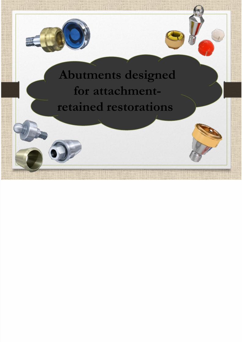
Abutments designed
for attachment-retained restorations

7/21/2019 mandibular overdenture (2).pdf
http://slidepdf.com/reader/full/mandibular-overdenture-2pdf 48/103
magnets

7/21/2019 mandibular overdenture (2).pdf
http://slidepdf.com/reader/full/mandibular-overdenture-2pdf 49/103
Locator abutment
components and
instruments

7/21/2019 mandibular overdenture (2).pdf
http://slidepdf.com/reader/full/mandibular-overdenture-2pdf 50/103
Locator
abutment withdifferent
gingival height.
Processing cap
7/21/2019 mandibular overdenture (2).pdf
http://slidepdf.com/reader/full/mandibular-overdenture-2pdf 51/103
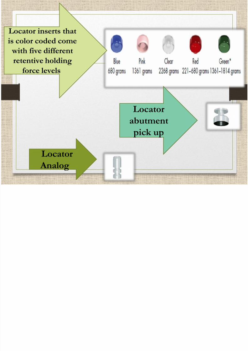
Locator inserts that
is color coded come
with five different
retentive holding
force levels
Locator
abutment
pick up
Locator
Analog

7/21/2019 mandibular overdenture (2).pdf
http://slidepdf.com/reader/full/mandibular-overdenture-2pdf 52/103
Locator Core
Tool

7/21/2019 mandibular overdenture (2).pdf
http://slidepdf.com/reader/full/mandibular-overdenture-2pdf 53/103
1. Locator Abutment Driver
for tightening of
abutment.2. Locator Insert Seating
Tool for seating an insert
into the titanium processingcap.
3. Locator Insert Removal
Tool for catching and pulling
the used insert out of the
permanent metal housing.
7/21/2019 mandibular overdenture (2).pdf
http://slidepdf.com/reader/full/mandibular-overdenture-2pdf 54/103
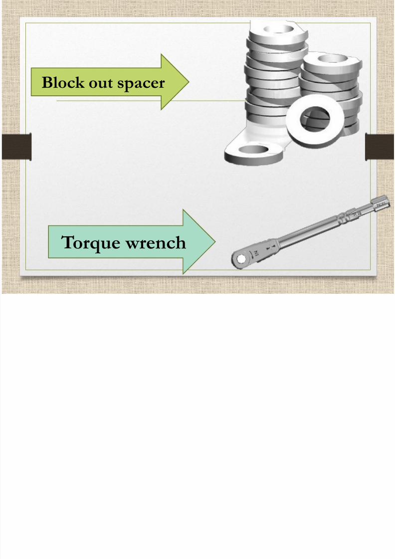
Block out spacer
Torque wrench

7/21/2019 mandibular overdenture (2).pdf
http://slidepdf.com/reader/full/mandibular-overdenture-2pdf 55/103
Clinical and
Laboratory procedure
for locator abutment

7/21/2019 mandibular overdenture (2).pdf
http://slidepdf.com/reader/full/mandibular-overdenture-2pdf 56/103
Abutment selection
The highest level of tissue
measured with the AbutmentDepth Gauge. This will allow
the retention groove to be at
the appropriate supra gingival
height.

7/21/2019 mandibular overdenture (2).pdf
http://slidepdf.com/reader/full/mandibular-overdenture-2pdf 57/103
Abutment selection
Please use extreme caution when measuring that you
do not add any additional
height to yourmeasurement.Order
exactly what you measure.
Measure 1mm = order1mm cuff
i t ll ti
7/21/2019 mandibular overdenture (2).pdf
http://slidepdf.com/reader/full/mandibular-overdenture-2pdf 58/103
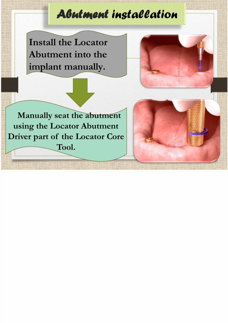
Abutment installation
Install the Locator Abutment into the
implant manually.
Manually seat the abutment
using the Locator Abutment
Driver part of the Locator Core
Tool.
Fi l ti ht i

7/21/2019 mandibular overdenture (2).pdf
http://slidepdf.com/reader/full/mandibular-overdenture-2pdf 59/103
Final tightening
With torque
wrench with
recommend
ed torque25 N/cm

7/21/2019 mandibular overdenture (2).pdf
http://slidepdf.com/reader/full/mandibular-overdenture-2pdf 60/103
attach the Locator Abutment Pick-up to
each Locator Abutment.
The pick-up should have
stable friction retention.
Take the abutment-level impression

7/21/2019 mandibular overdenture (2).pdf
http://slidepdf.com/reader/full/mandibular-overdenture-2pdf 61/103
Take the abutment level impression
in a customized impression tray
with an elastomeric impression
material.Remove the impression once the
impression material has set.
The black processing inserts of the

7/21/2019 mandibular overdenture (2).pdf
http://slidepdf.com/reader/full/mandibular-overdenture-2pdf 62/103
The black processing inserts of the
pick-ups should be clearly visible
within the impression. Send the
impression to the laboratory.
Place the abutment locator replica in

7/21/2019 mandibular overdenture (2).pdf
http://slidepdf.com/reader/full/mandibular-overdenture-2pdf 63/103
Place the abutment locator replica in
the locator abutment pick up then
pour the impression with stone to
have the working model
Pl h

7/21/2019 mandibular overdenture (2).pdf
http://slidepdf.com/reader/full/mandibular-overdenture-2pdf 64/103
Place the spacer over the head of each Locator
Abutment Replica providing primary soft tissue
support and a resilient situation. process and cureit into the overdenture.
Remove the overdenture and discard the spacer after
the acrylic has cured.
S d h fi l d i h h

7/21/2019 mandibular overdenture (2).pdf
http://slidepdf.com/reader/full/mandibular-overdenture-2pdf 65/103
Send the final overdenture with the
Locator Processing Cap and insert to the
clinician.

7/21/2019 mandibular overdenture (2).pdf
http://slidepdf.com/reader/full/mandibular-overdenture-2pdf 66/103
Converting an
existing denture chair
side
Pl h h h d f h
7/21/2019 mandibular overdenture (2).pdf
http://slidepdf.com/reader/full/mandibular-overdenture-2pdf 67/103
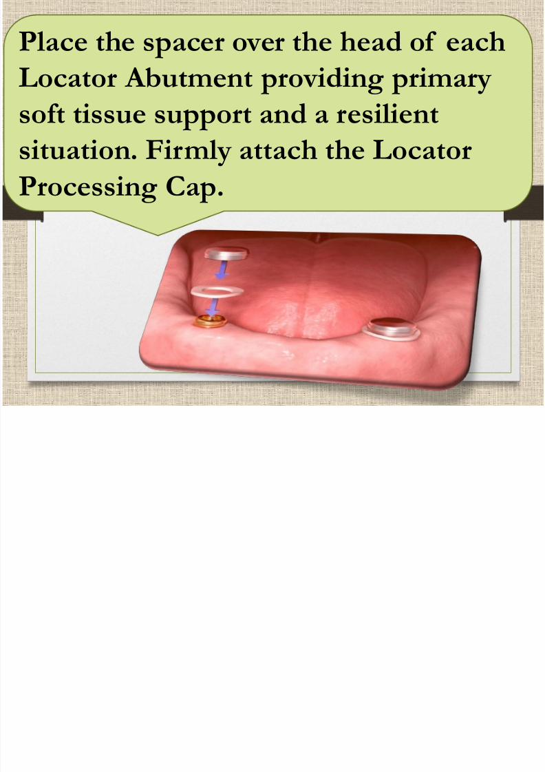
Place the spacer over the head of each
Locator Abutment providing primary
soft tissue support and a resilientsituation. Firmly attach the Locator
Processing Cap.
7/21/2019 mandibular overdenture (2).pdf
http://slidepdf.com/reader/full/mandibular-overdenture-2pdf 68/103
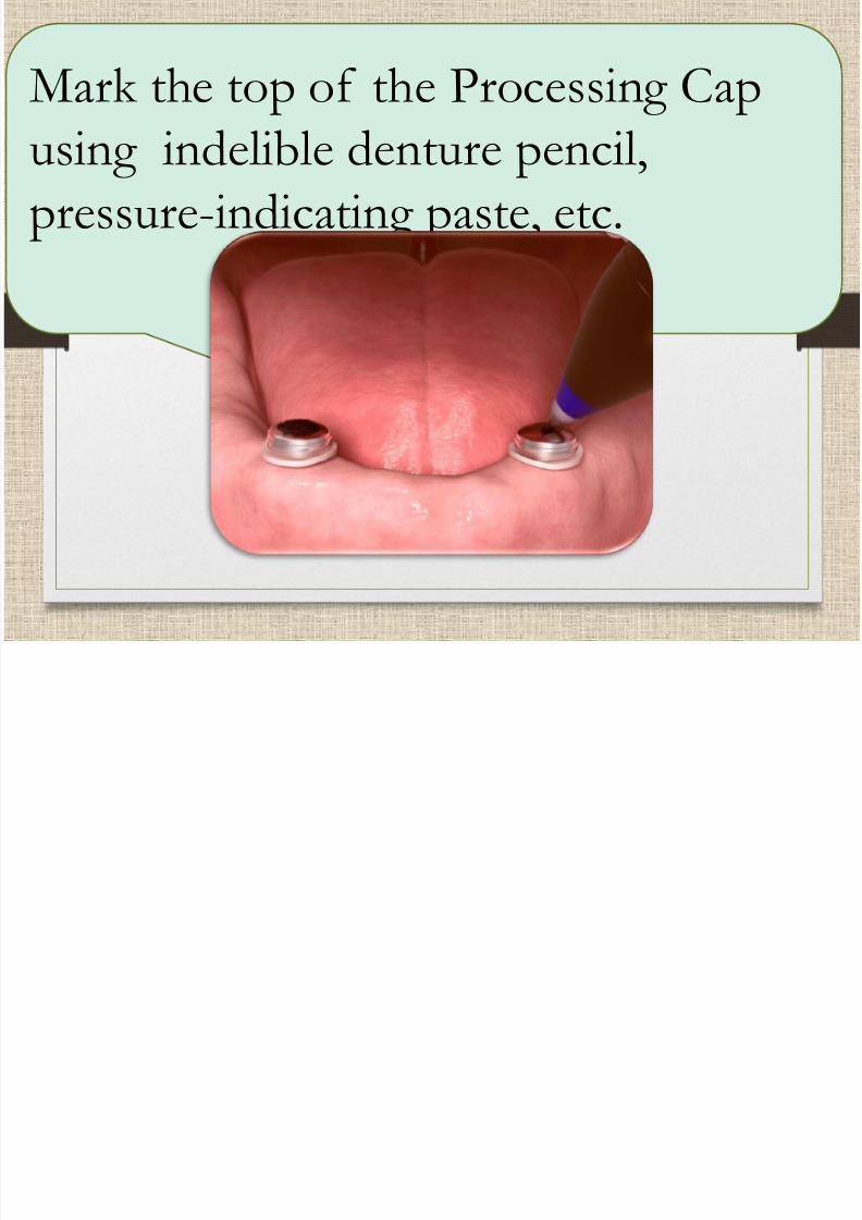
Mark the top of the Processing Cap
using indelible denture pencil,pressure-indicating paste, etc.

7/21/2019 mandibular overdenture (2).pdf
http://slidepdf.com/reader/full/mandibular-overdenture-2pdf 69/103
Use an acrylic laboratory burr to
relieve the denture base in theindicated areas
V t i t t t ll th

7/21/2019 mandibular overdenture (2).pdf
http://slidepdf.com/reader/full/mandibular-overdenture-2pdf 70/103
Vents are important to allow the
escape of excess material
7/21/2019 mandibular overdenture (2).pdf
http://slidepdf.com/reader/full/mandibular-overdenture-2pdf 71/103
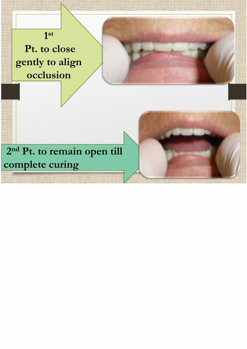
1st
Pt. to closegently to align
occlusion
2nd Pt. to remain open till
complete curing

7/21/2019 mandibular overdenture (2).pdf
http://slidepdf.com/reader/full/mandibular-overdenture-2pdf 72/103
Evaluate the pick up
1- check that
both attachment
are picked-up2-No voids
3- voids are
correctable if
the attachment
does not move
4-trim the excess

7/21/2019 mandibular overdenture (2).pdf
http://slidepdf.com/reader/full/mandibular-overdenture-2pdf 73/103
Remove Spacer from the Locator
Abutment. Remove the Processing
Insert from the Processing Cap in the
overdenture using the Locator Insert
Removal Tool.

7/21/2019 mandibular overdenture (2).pdf
http://slidepdf.com/reader/full/mandibular-overdenture-2pdf 74/103
Press the preferred Locator insert into the
Processing Cap’s metal housing, using theInsert Seating Tool.
Gradual loading is always recommended.

7/21/2019 mandibular overdenture (2).pdf
http://slidepdf.com/reader/full/mandibular-overdenture-2pdf 75/103

7/21/2019 mandibular overdenture (2).pdf
http://slidepdf.com/reader/full/mandibular-overdenture-2pdf 76/103
Components of ball attachment

7/21/2019 mandibular overdenture (2).pdf
http://slidepdf.com/reader/full/mandibular-overdenture-2pdf 77/103
Components of ball attachment

7/21/2019 mandibular overdenture (2).pdf
http://slidepdf.com/reader/full/mandibular-overdenture-2pdf 78/103
May be straight or angled
zest anchors develop
new saturno™ narrow
diameter implantsystem that have
straight and angled ball
attachment.

7/21/2019 mandibular overdenture (2).pdf
http://slidepdf.com/reader/full/mandibular-overdenture-2pdf 79/103
Magnetic attachment
• Magnet assembly
placed in denture and
flat keeper onabutment.
Advantages for magnetic
7/21/2019 mandibular overdenture (2).pdf
http://slidepdf.com/reader/full/mandibular-overdenture-2pdf 80/103
Advantages for magnetic
retainer
1. Not affecting the
denture path of
insertion2. Self-seating
denture
3. Maintenance issimpler

7/21/2019 mandibular overdenture (2).pdf
http://slidepdf.com/reader/full/mandibular-overdenture-2pdf 81/103
disadvantages
1. Less retention
intra oral
2.corrosion(which iscan be treated be
electroplating)

7/21/2019 mandibular overdenture (2).pdf
http://slidepdf.com/reader/full/mandibular-overdenture-2pdf 82/103
7/21/2019 mandibular overdenture (2).pdf
http://slidepdf.com/reader/full/mandibular-overdenture-2pdf 83/103
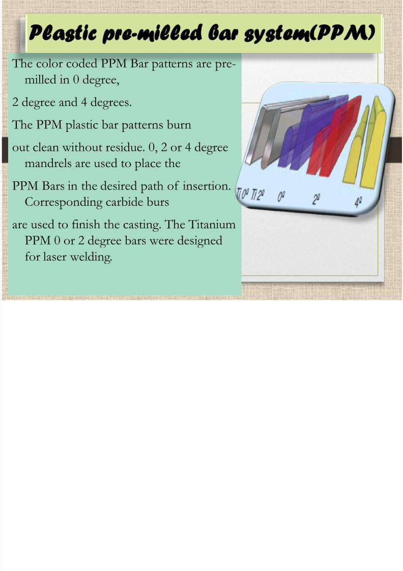
The color coded PPM Bar patterns are pre-
milled in 0 degree,
2 degree and 4 degrees.
The PPM plastic bar patterns burn
out clean without residue. 0, 2 or 4 degreemandrels are used to place the
PPM Bars in the desired path of insertion.
Corresponding carbide burs
are used to finish the casting. The Titanium
PPM 0 or 2 degree bars were designed
for laser welding.
Plastic pre-milled bar system PPM)

7/21/2019 mandibular overdenture (2).pdf
http://slidepdf.com/reader/full/mandibular-overdenture-2pdf 84/103
H d EDS B S t

7/21/2019 mandibular overdenture (2).pdf
http://slidepdf.com/reader/full/mandibular-overdenture-2pdf 85/103
Hader-EDS Bar System
The Bars plastic bars,
Titanium Bars for laser
welding and Gold Barsfor soldering or laser
welding
are now available.
The Housings:
The Clips:
The durable

7/21/2019 mandibular overdenture (2).pdf
http://slidepdf.com/reader/full/mandibular-overdenture-2pdf 86/103
The Housings: The gold-plated
machined metal Hader-EDS Housing simplifies
clip replacement and
prevents loosenesscaused by acrylic
breakdown.
The Clips: The durable
Hader-EDS Clips are
interchangeable with standardHader Clips and are available
in three color-coded levels of
retention.

7/21/2019 mandibular overdenture (2).pdf
http://slidepdf.com/reader/full/mandibular-overdenture-2pdf 87/103
The Analogs and
Impression Clips:• Plastic Hader-EDS
Impression Clips
•aluminum Hader-EDS
Bar Analogs are available
for the fabrication of
processing Models.

7/21/2019 mandibular overdenture (2).pdf
http://slidepdf.com/reader/full/mandibular-overdenture-2pdf 88/103
Clinical and
Laboratory procedure
for Bar abutment
Abutment height

7/21/2019 mandibular overdenture (2).pdf
http://slidepdf.com/reader/full/mandibular-overdenture-2pdf 89/103
g
selection

7/21/2019 mandibular overdenture (2).pdf
http://slidepdf.com/reader/full/mandibular-overdenture-2pdf 90/103
Remove thehealing abutment
Screwing the
abutment

7/21/2019 mandibular overdenture (2).pdf
http://slidepdf.com/reader/full/mandibular-overdenture-2pdf 91/103
Tighten the
uniabutment
pick up
Take theimpression

7/21/2019 mandibular overdenture (2).pdf
http://slidepdf.com/reader/full/mandibular-overdenture-2pdf 92/103
Screwing the
abutment
analoge to
have the
master model
Place the Semi

7/21/2019 mandibular overdenture (2).pdf
http://slidepdf.com/reader/full/mandibular-overdenture-2pdf 93/103
Place the Semi-
Burnout Cylinder on
the replica and
tighten it with a
Laboratory BridgeScrew. The plastic
part of the cylinders
are cut back toappropriate
dimensions.
Reduce the bar height, leaving a minimum of

7/21/2019 mandibular overdenture (2).pdf
http://slidepdf.com/reader/full/mandibular-overdenture-2pdf 94/103
g , g
2.5 mm to ensure a proper fit of the inserts.
Note: Do not grind the retention surfaceof the bar.
Attach the bar to the plastic sleeve with a
material that has a low polymerizationshrinkage.(duralay)
Processing

7/21/2019 mandibular overdenture (2).pdf
http://slidepdf.com/reader/full/mandibular-overdenture-2pdf 95/103
ocess g
Apply casting sprues
outside the functionalareas of the bar.
Invest, burnout and cast
with an appropriate metalalloy according to
standard working
procedures.
If we have metal bar

7/21/2019 mandibular overdenture (2).pdf
http://slidepdf.com/reader/full/mandibular-overdenture-2pdf 96/103
If we have metal bar
Investingsolderingthen

7/21/2019 mandibular overdenture (2).pdf
http://slidepdf.com/reader/full/mandibular-overdenture-2pdf 97/103
Finish and thoroughlypolish the bar. Protect the
margins of the cylinders
during grinding andpolishing by using the
Polishing Protectors.
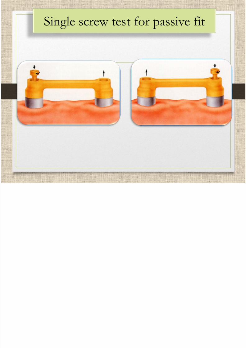
Single screw test for passive fit
7/21/2019 mandibular overdenture (2).pdf
http://slidepdf.com/reader/full/mandibular-overdenture-2pdf 98/103
Single screw test for passive fit
Spacing and blocking

7/21/2019 mandibular overdenture (2).pdf
http://slidepdf.com/reader/full/mandibular-overdenture-2pdf 99/103
Place the bar restoration on the
UniAbutment Replicas and tighten withthe Laboratory Bridge Screws. Press the
green plastic spacer onto the bar.
The spacer is used to enable positioning
of the Profile Bar Insert after
polymerization of the overdenture.
Block out the undercuts and
leave the spacers free. Cover the upper
free areas of the bar and theSemi-Burnout Cylinders
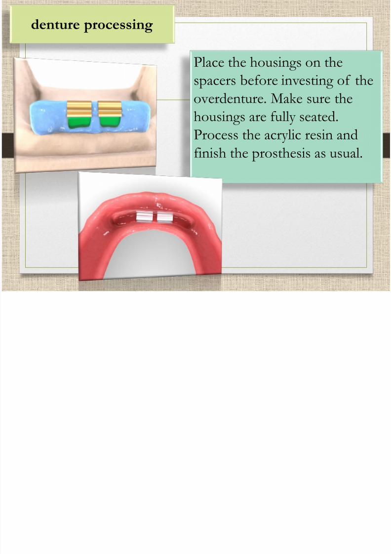
denture processing
7/21/2019 mandibular overdenture (2).pdf
http://slidepdf.com/reader/full/mandibular-overdenture-2pdf 100/103
Place the housings on the
spacers before investing of theoverdenture. Make sure the
housings are fully seated.
Process the acrylic resin and
finish the prosthesis as usual.
7/21/2019 mandibular overdenture (2).pdf
http://slidepdf.com/reader/full/mandibular-overdenture-2pdf 101/103
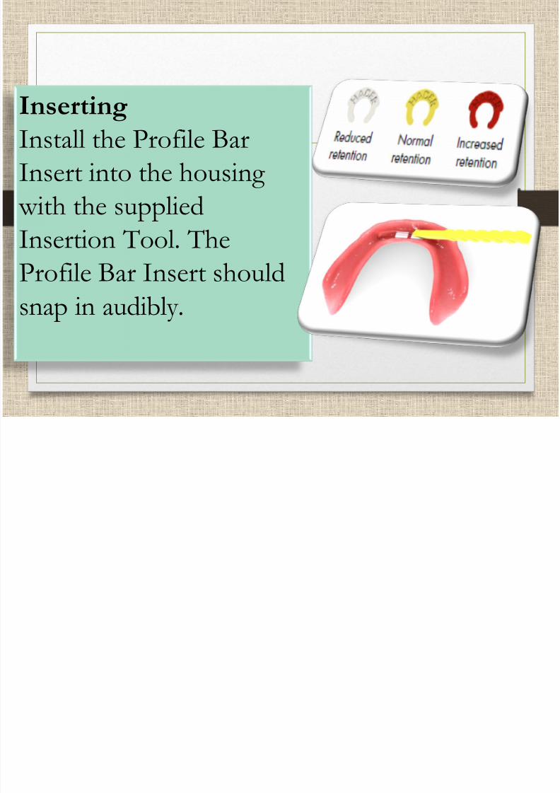
InsertingInstall the Profile Bar
Insert into the housing
with the suppliedInsertion Tool. The
Profile Bar Insert should
snap in audibly.
Matainance the bar

7/21/2019 mandibular overdenture (2).pdf
http://slidepdf.com/reader/full/mandibular-overdenture-2pdf 102/103
Matainance the bar

7/21/2019 mandibular overdenture (2).pdf
http://slidepdf.com/reader/full/mandibular-overdenture-2pdf 103/103