Mandal Thermomechanics of transient oblique compaction shock reflection from a rigid...
22
Shock Waves DOI 10.1007/s00193-015-0583-2 ORIGINAL ARTICLE Thermomechanics of transient oblique compaction shock reflection from a rigid boundary A. Mandal 1,2 · K. A. Gonthier 1 Received: 10 October 2014 / Revised: 29 June 2015 / Accepted: 6 July 2015 © Springer-Verlag Berlin Heidelberg 2015 Abstract Transient oblique reflection of resolved com- paction shocks in porous material from a rigid planar bound- ary is computationally examined to characterize how spatial reflection structures vary with reflection angle. The material response is described by a hydrodynamic theory that accounts for both elastic and inelastic volumetric deformation. The mathematical model, expressed in terms of curvilinear coor- dinates, is numerically integrated using a high-resolution technique. Emphasis is placed on characterizing the relative importance of compression and compaction work as heating mechanisms. Spatially continuous structures are predicted that propagate at speeds below the ambient sound speed of the solid component which are analogous to discontinuous structures for oblique reflection of gas shocks. An analo- gous transition from a von Neumann reflection to a Mach reflection to a regular reflection is predicted with increas- ing reflection angle, with high dissipative heating induced by configurations possessing a stem-like structure. Compres- sion and dissipation by rate-dependent compaction are shown to be primary heating mechanisms, whereas dissipation by inelastic compaction is of secondary importance. Keywords Porous materials · Compaction · Shocks · Solid explosives Communicated by F. Zhang and A. Higgins. B K. A. Gonthier [email protected] 1 Mechanical and Industrial Engineering Department, Louisiana State University, Baton Rouge, LA 70803, USA 2 Present Address: Institute for Shock Physics, Washington State University, Pullman, WA, USA 1 Introduction Porous materials, such as soils, propellants, and explosives, have a granular microstructure that makes their deformation behavior complex. The effective (or average) density of a single component material, given by ρ = ρ s φ, where ρ s is the solid component density and φ is the solid volume fraction, is lower than its theoretical maximum value due to the existence of pores between grains. Unlike homogeneous material, applied loads are transmitted by intergranular con- tact which causes appreciable inelastic deformation and pore collapse due to stress localization in the vicinity of contacts, even for applied loads that have substantially lower stress than the yield strength of the solid. The solid pressure is given by P s = P /φ, where P is the applied effective pres- sure, so that the stress intensification factor is given by 1/φ to leading order; thus, volume fraction plays a key role in establishing the material deformation behavior. Dissipation associated with pore collapse reduces the propagation speed of shocks and results in substantial hysteresis upon unload- ing which makes porous materials good shock attenuators. However, dissipation can result in intense pore-scale heating if the loading rate is sufficiently high, which is important for reactive solids because it may cause local combustion and trigger detonation [7, 16, 18–20, 22, 23, 26, 34, 35]. In this study, we computationally examine the scenario illustrated in Fig. 1 that involves the transient interaction of an initially steady, planar compaction shock propagating through porous material with a rigid boundary that is inclined at an angle θ from the horizontal axis. We use material properties that are representative of the high-explosive HMX (octahydro-1,3,5,7-tetranitro-1,3,5,7-tetrazocine), because it is commonly used in aerospace and defense applications, its compaction behavior is experimentally well characterized [5], and its detonation transition behavior has been exten- 123
-
Upload
bumbanirban -
Category
Documents
-
view
218 -
download
0
description
interaction between planar shock wave and non-planar rigid boundaries in an explosive medium.
Transcript of Mandal Thermomechanics of transient oblique compaction shock reflection from a rigid...

Shock WavesDOI 10.1007/s00193-015-0583-2
ORIGINAL ARTICLE
Thermomechanics of transient oblique compaction shockreflection from a rigid boundary
A. Mandal1,2 · K. A. Gonthier1
Received: 10 October 2014 / Revised: 29 June 2015 / Accepted: 6 July 2015© Springer-Verlag Berlin Heidelberg 2015
Abstract Transient oblique reflection of resolved com-paction shocks in porous material from a rigid planar bound-ary is computationally examined to characterize how spatialreflection structures vary with reflection angle. The materialresponse is describedby ahydrodynamic theory that accountsfor both elastic and inelastic volumetric deformation. Themathematical model, expressed in terms of curvilinear coor-dinates, is numerically integrated using a high-resolutiontechnique. Emphasis is placed on characterizing the relativeimportance of compression and compaction work as heatingmechanisms. Spatially continuous structures are predictedthat propagate at speeds below the ambient sound speed ofthe solid component which are analogous to discontinuousstructures for oblique reflection of gas shocks. An analo-gous transition from a von Neumann reflection to a Machreflection to a regular reflection is predicted with increas-ing reflection angle, with high dissipative heating inducedby configurations possessing a stem-like structure. Compres-sion and dissipation by rate-dependent compaction are shownto be primary heating mechanisms, whereas dissipation byinelastic compaction is of secondary importance.
Keywords Porous materials · Compaction · Shocks · Solidexplosives
Communicated by F. Zhang and A. Higgins.
B K. A. [email protected]
1 Mechanical and Industrial Engineering Department,Louisiana State University, Baton Rouge, LA 70803, USA
2 Present Address: Institute for Shock Physics, WashingtonState University, Pullman, WA, USA
1 Introduction
Porous materials, such as soils, propellants, and explosives,have a granular microstructure that makes their deformationbehavior complex. The effective (or average) density of asingle component material, given by ρ = ρsφ, where ρsis the solid component density and φ is the solid volumefraction, is lower than its theoretical maximum value due tothe existence of pores between grains. Unlike homogeneousmaterial, applied loads are transmitted by intergranular con-tact which causes appreciable inelastic deformation and porecollapse due to stress localization in the vicinity of contacts,even for applied loads that have substantially lower stressthan the yield strength of the solid. The solid pressure isgiven by Ps = P/φ, where P is the applied effective pres-sure, so that the stress intensification factor is given by 1/φto leading order; thus, volume fraction plays a key role inestablishing the material deformation behavior. Dissipationassociated with pore collapse reduces the propagation speedof shocks and results in substantial hysteresis upon unload-ing which makes porous materials good shock attenuators.However, dissipation can result in intense pore-scale heatingif the loading rate is sufficiently high, which is important forreactive solids because it may cause local combustion andtrigger detonation [7,16,18–20,22,23,26,34,35].
In this study, we computationally examine the scenarioillustrated in Fig. 1 that involves the transient interactionof an initially steady, planar compaction shock propagatingthrough porousmaterial with a rigid boundary that is inclinedat an angle θ from the horizontal axis. We use materialproperties that are representative of the high-explosive HMX(octahydro-1,3,5,7-tetranitro-1,3,5,7-tetrazocine), because itis commonly used in aerospace and defense applications, itscompaction behavior is experimentally well characterized[5], and its detonation transition behavior has been exten-
123
A. Mandal, K. A. Gonthier
Y
X
Granular HMX
WaveIncident
Non
−Ref
lect
ing
BC
Out
flow
BC
Symmetry BC
Non−Reflecting BC
Reflecting BCRigid Wall
θ
Fig. 1 A schematic of the simulation geometry
sively studied [1,11,12,25,28,30]. The initially unstressedmaterial has a solid volume fraction φ0 and is at ambientconditions. The initial compaction shock is supported bya fictitious far-field piston moving at constant speed Up.One-dimensional, steady-state solutions for the compactionshock spatial profile corresponding to prescribed values ofUp and φ0 are used to initialize the computational domain,as explained later. The propagation speed of the initial shock,which may be significantly lower than the ambient soundspeed of the solid component, is given by the Hugoniot rela-tion D = D(Up;φ0). A key objective of this study is tocomputationally examine how θ and φ0 affect the tempo-ral and spatial development of interaction structures in thevicinity of the planar surface, with emphasis placed on char-acterizing heating within these structures by compressionand compaction work. We focus on inert heating to isolatethe incipient thermomechanical events that give rise to igni-tion from the subsequent chemistry. As such, the analysisgiven in this paper is generally applicable to inert poroussolids.
Compaction of porous solids is associated with signifi-cant volume change. Though volumetric deformation can beaffected bydeviatoric stresses for lowpressure loading result-ing in shear enhanced compaction, pressures associated withreflection structures analyzed in this study are sufficientlyhigh that deviatoric stresses may be ignored. To account for
hysteresis, it is necessary to partition changes in solid vol-ume fraction into dφ = dφe + d˜φ, where φe and ˜φ are theelastic and inelastic components of volume fraction, respec-tively [11,12]. The evolution of ˜φ is prescribed by a yieldsurface that expands with φ to account for strain hardening asthe material is compacted causing an increase in compactionpotential energy.
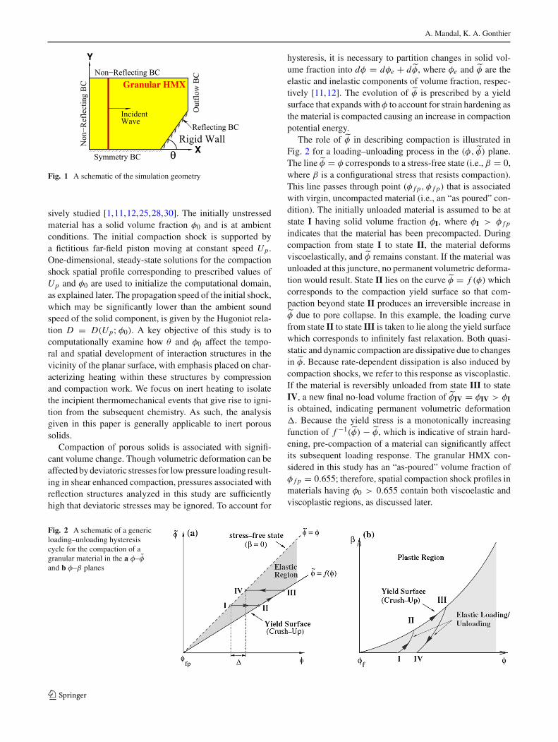
The role of ˜φ in describing compaction is illustrated inFig. 2 for a loading–unloading process in the (φ, ˜φ) plane.The line˜φ = φ corresponds to a stress-free state (i.e., β = 0,where β is a configurational stress that resists compaction).This line passes through point (φ f p, φ f p) that is associatedwith virgin, uncompacted material (i.e., an “as poured” con-dition). The initially unloaded material is assumed to be atstate I having solid volume fraction φI, where φI > φ f p
indicates that the material has been precompacted. Duringcompaction from state I to state II, the material deformsviscoelastically, and ˜φ remains constant. If the material wasunloaded at this juncture, no permanent volumetric deforma-tion would result. State II lies on the curve ˜φ = f (φ) whichcorresponds to the compaction yield surface so that com-paction beyond state II produces an irreversible increase in˜φ due to pore collapse. In this example, the loading curvefrom state II to state III is taken to lie along the yield surfacewhich corresponds to infinitely fast relaxation. Both quasi-static and dynamic compaction are dissipative due to changesin ˜φ. Because rate-dependent dissipation is also induced bycompaction shocks, we refer to this response as viscoplastic.If the material is reversibly unloaded from state III to stateIV, a new final no-load volume fraction of ˜φIV = φIV > φI
is obtained, indicating permanent volumetric deformation�. Because the yield stress is a monotonically increasingfunction of f −1(˜φ) − ˜φ, which is indicative of strain hard-ening, pre-compaction of a material can significantly affectits subsequent loading response. The granular HMX con-sidered in this study has an “as-poured” volume fraction ofφ f p = 0.655; therefore, spatial compaction shock profiles inmaterials having φ0 > 0.655 contain both viscoelastic andviscoplastic regions, as discussed later.
Fig. 2 A schematic of a genericloading–unloading hysteresiscycle for the compaction of agranular material in the a φ–φand b φ–β planes
123
Thermomechanics of transient oblique compaction shock reflection from a rigid boundary
2RM >1
θ
R
(0)(1)
i
straight reflected wave
r(2)
RR
2MR<1
< 90 οψ
θ
R
(1)SMR
mT
r
s
(0)i
(2)
straight Mach stem
2MR <1
ψ > 90ο
θ
Rr
i (0)(1)
vNR
curved Mach stem
mT
(2)
(c)(b)(a)
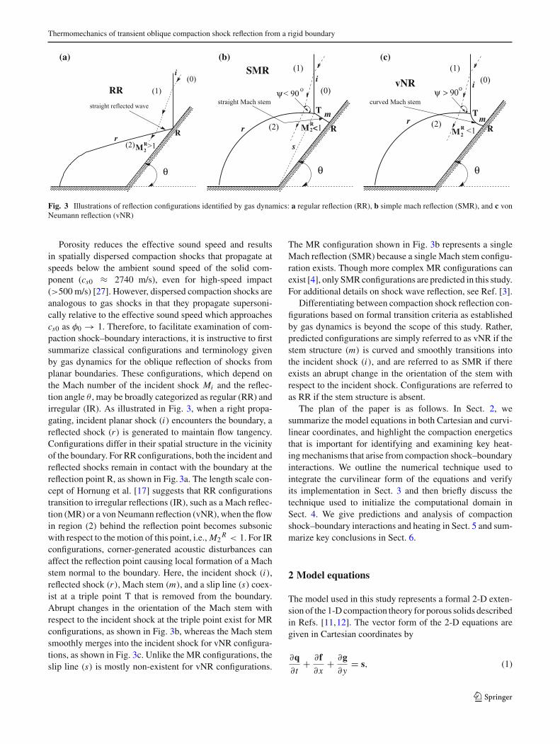
Fig. 3 Illustrations of reflection configurations identified by gas dynamics: a regular reflection (RR), b simple mach reflection (SMR), and c vonNeumann reflection (vNR)
Porosity reduces the effective sound speed and resultsin spatially dispersed compaction shocks that propagate atspeeds below the ambient sound speed of the solid com-ponent (cs0 ≈ 2740 m/s), even for high-speed impact(>500 m/s) [27]. However, dispersed compaction shocks areanalogous to gas shocks in that they propagate supersoni-cally relative to the effective sound speed which approachescs0 as φ0 → 1. Therefore, to facilitate examination of com-paction shock–boundary interactions, it is instructive to firstsummarize classical configurations and terminology givenby gas dynamics for the oblique reflection of shocks fromplanar boundaries. These configurations, which depend onthe Mach number of the incident shock Mi and the reflec-tion angle θ , may be broadly categorized as regular (RR) andirregular (IR). As illustrated in Fig. 3, when a right propa-gating, incident planar shock (i) encounters the boundary, areflected shock (r) is generated to maintain flow tangency.Configurations differ in their spatial structure in the vicinityof the boundary. For RR configurations, both the incident andreflected shocks remain in contact with the boundary at thereflection point R, as shown in Fig. 3a. The length scale con-cept of Hornung et al. [17] suggests that RR configurationstransition to irregular reflections (IR), such as a Mach reflec-tion (MR) or a vonNeumann reflection (vNR), when the flowin region (2) behind the reflection point becomes subsonicwith respect to themotion of this point, i.e.,M2
R < 1. For IRconfigurations, corner-generated acoustic disturbances canaffect the reflection point causing local formation of a Machstem normal to the boundary. Here, the incident shock (i),reflected shock (r), Mach stem (m), and a slip line (s) coex-ist at a triple point T that is removed from the boundary.Abrupt changes in the orientation of the Mach stem withrespect to the incident shock at the triple point exist for MRconfigurations, as shown in Fig. 3b, whereas the Mach stemsmoothly merges into the incident shock for vNR configura-tions, as shown in Fig. 3c. Unlike the MR configurations, theslip line (s) is mostly non-existent for vNR configurations.
The MR configuration shown in Fig. 3b represents a singleMach reflection (SMR) because a single Mach stem configu-ration exists. Though more complex MR configurations canexist [4], only SMRconfigurations are predicted in this study.For additional details on shock wave reflection, see Ref. [3].
Differentiating between compaction shock reflection con-figurations based on formal transition criteria as establishedby gas dynamics is beyond the scope of this study. Rather,predicted configurations are simply referred to as vNR if thestem structure (m) is curved and smoothly transitions intothe incident shock (i), and are referred to as SMR if thereexists an abrupt change in the orientation of the stem withrespect to the incident shock. Configurations are referred toas RR if the stem structure is absent.
The plan of the paper is as follows. In Sect. 2, wesummarize the model equations in both Cartesian and curvi-linear coordinates, and highlight the compaction energeticsthat is important for identifying and examining key heat-ingmechanisms that arise from compaction shock–boundaryinteractions. We outline the numerical technique used tointegrate the curvilinear form of the equations and verifyits implementation in Sect. 3 and then briefly discuss thetechnique used to initialize the computational domain inSect. 4. We give predictions and analysis of compactionshock–boundary interactions and heating in Sect. 5 and sum-marize key conclusions in Sect. 6.
2 Model equations
The model used in this study represents a formal 2-D exten-sion of the 1-Dcompaction theory for porous solids describedin Refs. [11,12]. The vector form of the 2-D equations aregiven in Cartesian coordinates by
∂q∂t
+ ∂f∂x
+ ∂g∂y
= s, (1)
123

A. Mandal, K. A. Gonthier
where
q =[
ρsφ, ρsφu, ρsφv, ρsφE, ρsφ2, ρsφ˜φ
]�, (2)
f =[
ρsφu, ρsφu2 + Psφ, ρsφuv, ρsφu
(
E + Psρs
)
,
ρsφ2u, ρsφ˜φu
]�, (3)
g =[
ρsφv, ρsφuv, ρsφv2 + Psφ, ρsφv
(
E + Psρs
)
,
ρsφ2v, ρsφ˜φv
]�, (4)
s =[
0, 0, 0, 0,ρsφ
2 (1 − φ)
μ(Ps − β) , ρsφΛ
]�, (5)
and Λ is defined by
Λ ={ 1
μ
(
f (φ) − ˜φ)
if f (φ) > ˜φ
0 otherwise.(6)
Vector components in (1)–(6) describe the evolution ofmass, x-momentum, y-momentum, total energy, solid vol-ume fraction, and inelastic volume fraction of the material,respectively. Independent variables are time t , and positions xand y. Dependent variables not already defined are: solid den-sityρs; velocity components u and v in the x and y directions;solid pressure Ps; and mass-specific total energy E given byE = es + B + (
u2 + v2)
/2, where es is the mass-specific
internal energy of the solid and B = ∫ (φ−˜φ)
0β
ρsφd(φ − ˜φ)
is the mass-specific compaction potential energy. The con-figurational (or intergranular) stress β, which is empiricallydetermined, implicitly accounts for contact forces betweengrains that collectively resist compaction. The granularmate-rial deforms volumetrically due to an imbalance between Psand β. In (6), f (φ) is the compaction yield function thatdetermines the onset of inelastic volumetric deformation.Theparameters μ and μ in (5) and (6) establish the rates of stressequilibration (Ps → β) and relaxation to the yield surface(˜φ → f ). The value of μ, referred to as the compactionviscosity, is typically chosen so that the model predictscompaction shock thicknesses that are commensurate withdata. The value of μ is chosen based on quasi-static com-paction data. These equations are mathematically closed byspecifying the constitutive relations Ps (ρs, Ts), es (ρs, Ts),β
(
ρs, φ, ˜φ)
, and f (φ), where Ts is the solid temperature.Relations appropriate for granular HMX are summarized inAppendix 1.
Because a key focus of this study is to examine dissipativeheating, it is necessary to combine (1)–(6) with the secondlaw of thermodynamics to identify compatible dissipationmechanisms. The strong form of the dissipation inequality isgiven by
Tsdη
dt= des
dt− Ps
ρ2s
dρsdt
= (1 − φ)
μρs(Ps − β)2 + β
ρsφ
d˜φ
dt≥ 0, (7)
where η = ηs is the mass-specific granular solid entropy.The first term on the right side of (7) is non-negative, as isthe second term because β ≥ 0 and d˜φ/dt ≥ 0 within thecontext of this theory; these terms correspond to separate dis-sipative compaction mechanisms, as discussed below. Thisthermodynamic description is compatible with a Helmholtzfree energy of the form ψ
(
ρs, Ts, φ, ˜φ) = ψs (ρs, Ts) +
B(
φ − ˜φ)
, where ψs is the mass-specific solid free energy[2,10]. Here,ψs is the thermal component of free energy andB is the recoverable compaction energy.
Of particular significance are the heating rate and tem-perature rise experienced by the solid due to compaction andcompressionwhich can trigger combustion of reactive solids.Energy is dissipated within the material due to irreversiblecompaction work prescribed by (7), whereas the compres-sion work is recoverable. As rigorously shown in Ref. [24],the time rate of change in mass-specific thermal energy ofthe solid can be partitioned as
desdt
= deφ
dt+ de
˜φ
dt︸ ︷︷ ︸
compaction
+ deρ
dt︸︷︷︸
compression
= decdt
+ deρ
dt, (8)
where d (•) /dt ≡ ∂ (•) /∂t + v · ∇ (•) is the Lagrangianderivative. The compaction-induced heating rate dec/dt con-sists of a rate-dependent component deφ/dt , given by thefirst term in (7), which vanishes in the slow compaction limit(Ps → β), and an inelastic component de
˜φ/dt , given by thesecond term in (7), which accounts for inelastic (or perma-nent) volumetric deformation. The term deρ/dt accounts forcompressive heating of the solid. For convenience, we definethe following rates:
eφ ≡ deφ
dt= (Ps − β)
ρsφ
dφ
dt, (9)
e˜φ ≡ de
˜φ
dt= β
ρsφ
d˜φ
dt, (10)
eρ ≡ deρ
dt= Ps
ρs2
dρsdt
, (11)
and
ec ≡ decdt
= eφ + e˜φ = (Ps − β)
ρsφ
dφ
dt+ β
ρsφ
d˜φ
dt, (12)
123

Thermomechanics of transient oblique compaction shock reflection from a rigid boundary
where
dφ
dt= φ (1 − φ)
μ(Ps − β) , (13)
d˜φ
dt=
{
f ′(φ)dφdt if f (φ) > ˜φ
0 otherwise.(14)
Here, f ′ ≡ d f/dφ is prescribed by the compaction yieldfunction.
The temperature rise of the solid with respect to theambient temperature T0 can be established from its caloricequation of state Ts(ρs, es), where es is computed by inte-gration of (1)–(6). For a calorically ideal equation of state,�T ≡ Ts − T0 = es/cv , where cv is the constant volumespecific heat. From (8), we have that es = eφ + e
˜φ + eρ ; inte-grating this expression with respect to time enables the totaltemperature rise to be partitioned into contributions due tocompaction and compression: i.e.,�T = �Tφ+�T
˜φ+�Tρ ,where
�Tφ = eφ
cv
, �T˜φ = e
˜φ
cv
, �Tρ = eρ
cv
. (15)
Here, internal energies are relative to the ambient state. Onlycompression is permitted to have a negative temperaturechange based on the second law of constraints. To facili-tate integration of (9)–(11) for use with (15), it is convenientto express them in terms of Eulerian coordinates using themass equation given by the first vector component of (1):
∂
∂t
(
ρsφeφ
) + ∂
∂x
(
ρsφueφ
) + ∂
∂y
(
ρsφveφ
)
= (Ps − β)dφ
dt, (16)
∂
∂t
(
ρsφe˜φ
)
+ ∂
∂x
(
ρsφue˜φ
)
+ ∂
∂y
(
ρsφve˜φ
)
= βd˜φ
dt. (17)
Once eφ and e˜φ are computed from (16) and (17), then eρ is
given by eρ = es −(
eφ + e˜φ
)
.
2.1 Curvilinear coordinates
The model equations are expressed in terms of general-ized curvilinear coordinates to facilitate their integration oncomplex domains. Using the generic spatial transformationsξ = ξ(x, y, t) and η = η(x, y, t), and the temporal trans-formation τ = t , the conservative, curvilinear form of thegoverning equations is given by
∂q∂τ
+ ∂ f∂ξ
+ ∂ g∂η
= s, (18)
where q = q/J, f = (ξtq+ ξx f + ξyg)/J, g = (ηtq+ ηx f +ηyg)/J, and s = s/J. Using the flux and source terms from(1)–(6), we obtain
q =1
J
[
ρsφ, ρsφu, ρsφv, ρsφE, ρsφ2, ρsφ˜φ
]�, (19)
f =1
J
[
ρsφUc, ρsφuU
c + ξx Psφ, ρsφvUc + ξy Psφ,
ρsφHUc − ξt Psφ, ρsφ2Uc, ρsφ˜φUc
]�, (20)
g =1
J
[
ρsφVc, ρsφuV
c + ηx Psφ, ρsφvV c + ηy Psφ,
ρsφHV c − ηt Psφ, ρsφ2V c, ρsφ˜φV c
]�, (21)
s =1
J
[
0, 0, 0, 0,ρsφ
2 (1 − φ)
μ(Ps − β) , ρsφΛ
]�,
(22)
where J = 1/(xξ yη − yξ xη) is the transformation Jacobianand H = (E + Ps/ρs) is the mass-specific total enthalpy ofthe material. Because fixed (time-invariant) computationalgrids are used in this study, ξt = ηt = 0; here, subscriptsdenote partial differentiation with respect to the designatedvariables. The remaining grid metrics are given by
ξx = yηJ, ξy = −xηJ, ξt = (xηyτ − xτ yη)J,
ηx = −yξ J, ηy = xξ J, ηt = (xτ yξ − xξ yτ )J. (23)
The contravariant velocitiesUc = ξxu+ξyv andV c = ηxu+ηyv in (20) and (21) represent velocities along coordinatelines ξ and η, respectively.
An eigenstructure analysis of (18)–(22) is important forimplementation of the numerical technique which requiresknowledge of the characteristic speeds. These speeds, which
are eigenvalues of the Jacobianmatrices ˆA ≡ ∂ f∂q and ˆB ≡ ∂ g
∂qare given by
λ1,2,3,4 = Uc, λ5 = Uc − c√
ξ2x + ξ2y ,
λ6 = Uc + c√
ξ2x + ξ2y , (24)
μ1,2,3,4 = V c, μ5 = V c − c√
η2x + η2y,
μ6 = V c + c√
η2x + η2y, (25)
where λi and μi (i = 1, . . . , 6) are speeds in the ξ and η
directions, respectively, and c is the local sound speed of thesolid component. Though some eigenvalues are degenerate,their corresponding eigenvectors are real and distinct; conse-quently, the equations constitute a strongly hyperbolic systemwhich can be numerically integrated once suitable initial andboundary conditions are supplied. Details of the coordinatetransformation and eigenstructure analysis are given in [24].
123
A. Mandal, K. A. Gonthier
3 Numerical technique
The transformed equations [(18)–(22)] are numerically inte-grated using a time step splitting procedure [33] that enablesthe coupling of a numerical method for nonlinear convectionand a separate method for local processes such as com-paction. The splitting recipe is given by
qn+2 = L�τc L2�τ
s L�τc qn, (26)
where qn and qn+2 are numerical approximations for q attimes τ n = τ 0 + n�τ and τ n+2 = τ 0 + (n + 2)�τ , respec-tively, τ 0 is the initial time, and �τ is the integration timeincrement.Here,L�τ
c denotes the convective numerical oper-ation, and L2�τ
s denotes the source numerical operation.Source terms in (18) are set to zero for the convective oper-ation, whereas the convective terms are set to zero for thesource operation:
∂q∂τ
+ ∂ f∂ξ
+ ∂ g∂η
= 0, (convection) (27)
∂q∂τ
= s. (source) (28)
Given the solution at the current time qn , the splitting reciperequires that the convective operations be performed overtime increments of �τ , and that the source operation be per-formed over a time increment of 2�τ , to advance the solutionto time τ n+2. The first convective operation provides initialconditions (ICs) for the source operation, which in turn pro-vides ICs for the final convective operation. The procedureis repeated until the desired final time is reached.
The convective operation [(27)] is numerically integratedusing a conservative, total variation diminishing (TVD), cen-tral finite-difference technique that can accurately track andpropagate shocks [21]. The equations are integrated on afixedcomputational domain that is discretized into Nξ and Nη
evenly spaced rectangular cells of width �ξ = 1/Nξ and�η = 1/Nη. Cell centers are located at positions (ξ j , ηk)
and their corresponding cell interfaces are located along thesurfaces defined by ξ j±1/2 = ξ j±�ξ and ηk±1/2 = ηk±�η.The semi-discrete, finite volume representation of (27) isgiven by
d
dτq j,k(τ ) = − F j+1/2,k − F j−1/2,k
�ξ
− G j,k+1/2 − G j,k−1/2
�η, (29)
where F j±1/2,k = F j±1/2,k(τ ) and G j,k±1/2 = G j,k±1/2(τ )
are the numerical flux functions
F j±1/2,k(τ ) ≡f(
q+j±1/2,k(τ )
)
+ f(
q−j±1/2,k(τ )
)
2
− aξj±1/2,k(τ )
2
[
q+j±1/2,k(τ ) − q−
j±1/2,k(τ )]
,
(30)
G j,k±1/2(τ ) ≡g
(
q+j,k±1/2(τ )
)
+ g(
q−j,k±1/2(τ )
)
2
− aηj,k±1/2(τ )
2
[
q+j,k±1/2(τ ) − q−
j,k±1/2(τ )]
.
(31)
The extrapolated states at cell boundaries contained in (30)and (31) are defined by
q±j+1/2,k(τ ) ≡ q j+1/2±1/2,k(τ ) ∓ �ξ
2
(
qξ
)
j+1/2±1/2,k (τ ),
(32)
q±j−1/2,k(τ ) ≡ q j−1/2±1/2,k(τ ) ∓ �ξ
2
(
qξ
)
j−1/2±1/2,k (τ ),
(33)
q±j,k+1/2(τ ) ≡ q j,k+1/2±1/2(τ ) ∓ �η
2
(
qη
)
j,k+1/2±1/2 (τ ),
(34)
q±j,k−1/2(τ ) ≡ q j,k−1/2±1/2(τ ) ∓ �η
2
(
qη
)
j,k−1/2±1/2 (τ ),
(35)
and the local speeds, aξj±1/2,k(τ ) and aη
j,k±1/2(τ ), are definedby
aξj+1/2,k(τ ) ≡ max ρ
(
∂ f∂q
(
q±j+1/2,k(τ )
)
)
, (36)
aξj−1/2,k(τ ) ≡ max ρ
(
∂ f∂q
(
q±j−1/2,k(τ )
)
)
, (37)
aηj,k+1/2(τ ) ≡ max ρ
(
∂ g∂q
(
q±j,k+1/2(τ )
)
)
. (38)
aηj,k−1/2(τ ) ≡ max ρ
(
∂ g∂q
(
q±j,k−1/2(τ )
)
)
. (39)
If λi (A) are the eigenvalues of A, then the operatorρ(A) ≡ maxi |λi (A)| in (36)–(39) denotes its spectral radius.Numerical derivatives in (32)–(35) are computed using thefollowing one-parameter family of minmod limiters:
(
qξ
)nj,k ≡ minmod
(
θqnj,k − qnj−1,k
�ξ,qnj+1,k − qnj−1,k
2�ξ,
θqnj+1,k − qnj,k
�ξ
)
, 1 ≤ θ ≤ 2 (40)
123
Thermomechanics of transient oblique compaction shock reflection from a rigid boundary
(
qη
)nj,k ≡ minmod
(
θqnj,k − qnj,k−1
�η,qnj,k+1 − qnj,k−1
2�η,
θqnj,k+1 − qnj,k
�η
)
, 1 ≤ θ ≤ 2 (41)
where the multivariable minmod function is defined by
minmod (x1, x2, · · · ) =⎧
⎨
⎩
min j {x j }, if x j > 0 ∀ j,max j {x j }, if x j < 0 ∀ j,0, otherwise.
(42)
Here, the value θ = 1 ensures a nonoscillatory solution,whereas higher values result in larger dispersive errors. Inthis study, we take θ = 1.2 which resulted in optimal perfor-mance based on shock tube simulations. To ensure numericalstability, the time increment �τ n was computed so that thefollowing Courant–Friedrich–Lewy (CFL) condition holds:
CFL = max
(
�τ n
�ξaξ (τ n),
�τ n
�ηaη(τ n)
)
≤ 1, (43)
where aξ and aη are maximum characteristic speeds in the ξ
and η directions at time τ n , respectively. Amore conservativevalue ofCFL = 0.475was used for all simulations performedin this study.
The semi-discrete system of nonlinear ODEs, given by(29), is integrated in time using a third-order Runge–Kutta(RK) technique. To this end, if C[q] denotes the right side of(29)
C[q] ≡ −[
F j+1/2,k(q) − F j−1/2,k(q)
�ξ
+G j,k+1/2(q) − G j,k−1/2(q)
�η
]
, (44)
then the one-parameter family of RK schemes [32] is givenby
q(1) = qn + �τ nC[qn] (45)
q(l+1) = ηl qn + (1 − ηl)(
q(l) + �τ nC[
q(l)])
,
l = 1, 2, . . . , s − 1, (46)
qn+1 = q(s), (47)
where s = 3, η1 = 3/4, and η2 = 1/3.For the source operation [(28)], an implicit stiff ODE
solver contained in the package LSODE (Livermore Solverfor Ordinary Differential Equations) is used to numericallyintegrate the equations. The solver is nominally fourth-orderaccurate in time, though the overall temporal accuracy of
the numerical technique is third-order due to the convectiveoperation. LSODEwas chosen because it is a convenient andwell-tested package for solving stiff systems of ODEs.
3.1 Verification
Verification of the computational technique and its imple-mentation was established based on (1) steady supersonicgas flow past a wedge and (2) steady, 1-D compaction shockprofiles in granular HMX. The first case was used to verifythe implementation of grid metrics and boundary conditionson a 2-D domain, and the second case was used to verify theimplementation of convective fluxes and source terms for aproblem that is directly relevant to this study. In this section,we only demonstrate verification based on 1-D compactionshock profiles for brevity; a detailed discussion all verifica-tion cases is given in Ref. [24].
We simulate the impact of initially unstressed material bya planar rigid piston having constant velocity Up. Equations(18)–(22) are numerically integrated on a piston-attached 2-D rectangular physical domain having an initially uniformvelocity field given by u(x, y, 0) = −Up and v(x, y, 0) = 0.The piston, located at the left domain boundary is stationaryin this frame. A reflecting condition is imposed on the leftdomain boundary and a non-reflecting condition is imposedat all remaining boundaries. These conditions result in theformation of a 1-D, right-propagating, steady compactionshockprofile that can be compared to that given by the steady-state analysis described in the following section. The steadyshock propagateswith speed D−Up , where D is its speed in alaboratory frame. The constitutive relations given in Appen-dix 1 were used for this case.
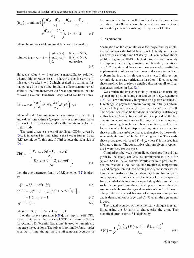
Comparisons between the predicted shock profile and thatgiven by the steady analysis are summarized in Fig. 4 forφ0 = 0.85 andUp = 300 m/s. Profiles for solid pressure Ps,volume fraction φ, no-load volume fraction φ, temperatureTs, and compaction-induced heating rate ec are shown whichhave been transformed to the laboratory frame for compari-son purposes. The shock causes the material to be compactedfrom its initial state to a final compacted equilibrium state; assuch, the compaction-induced heating rate has a pulse-likestructure which provides a good measure of shock thickness.The profile is dispersed because of compaction dissipationand is dependent on both φ0 and Up. Overall, the agreementis good.
The spatial accuracy of the numerical technique is estab-lished using the L2-norm to characterize the error. Thenumerical error at time tn is defined by
E(
tn) = 1
N
√
∑Nξ
j=1
(
P(
x j , tn) − P
(
x j , tn)
)2
Pref, (48)
123
A. Mandal, K. A. Gonthier
Fig. 4 Comparison of spatial profiles obtained by the steady andunsteady analysis for the steady compaction shock verification case forφ0 = 0.85 and impact speedUp = 300 m/s: a solid pressure Ps, b solid
volume fraction φ and its inelastic component φ, c solid temperatureTs, and d dissipative heating rate ec
where P(
x j , tn)
is the numerically determined pressure at a
spatial location x = x j along a fixed grid line k, P(
x j , tn)
is the analytical pressure at the same location, and Pref is anon-zero reference pressure used to non-dimensionalize theequation [36]. The spatial convergence rate κ is estimatedby varying the value of Nξ and computing the correspond-ing error, plotting log(E) against log(1/Nξ ), and fitting theresulting data using linear regression; the slope of the best-fitline represents the convergence rate.
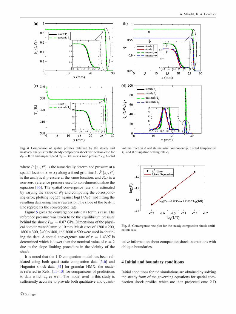
Figure 5 gives the convergence rate data for this case. Thereference pressure was taken to be the equilibrium pressurebehind the shock Pref = 0.87 GPa. Dimensions of the physi-cal domain were 60mm× 10mm.Mesh sizes of 1200×200,1800×300, 2400×400, and 3000×500 were used in obtain-ing the data. A spatial convergence rate of κ = 1.4397 isdetermined which is lower than the nominal value of κ = 2due to the slope limiting procedure in the vicinity of theshock.
It is noted that the 1-D compaction model has been val-idated using both quasi-static compaction data [5,6] andHugoniot shock data [31] for granular HMX; the readeris referred to Refs. [11–13] for comparisons of predictionsto data which agree well. The model used in this study issufficiently accurate to provide both qualitative and quanti-
Fig. 5 Convergence rate plot for the steady compaction shock verifi-cation case
tative information about compaction shock interactions withoblique boundaries.
4 Initial and boundary conditions
Initial conditions for the simulations are obtained by solvingthe steady form of the governing equations for spatial com-paction shock profiles which are then projected onto 2-D
123

Thermomechanics of transient oblique compaction shock reflection from a rigid boundary
Fig. 6 Representative compaction shock profiles given by the steady analysis forφ0 = 0.85: aUp = 150m/s,bUp = 300m/s, and cUp = 500m/s
computational domains using high-order interpolation. Thistechnique is beneficial because it enables the incident shockprofile to be characterized a priori for a given simulation. Thesteady shock analysis is briefly summarized in this sectionand features of compaction shock profiles are highlighted; adetailed exposition of the analysis technique is given in Refs.[12,13]. The conditions imposed on computational bound-aries are indicated in Fig. 1.
The steady analysis expresses the 1-D form of (1)–(5) ina right propagating shock-attached frame using the transfor-mations ζ = x − Dt and w = u − D, where ζ and w areposition and velocity measured in this frame. Substituting
Table 1 Mach numbers of the incident compaction shock
φ0 Up (m/s) D (m/s) Mi
0.85 150.0 1144.0 2.26
300.0 1774.0 3.50
500.0 2472.5 4.88
the derivatives ∂∂t
∣
∣
x = −D ∂∂ζ
∣
∣
∣
t+ ∂
∂t
∣
∣
ζand ∂
∂x
∣
∣
t = ∂∂ζ
∣
∣
∣
tinto these equations, imposing ∂
∂t ≡ 0, and simplifying theresult, give
123
A. Mandal, K. A. Gonthier
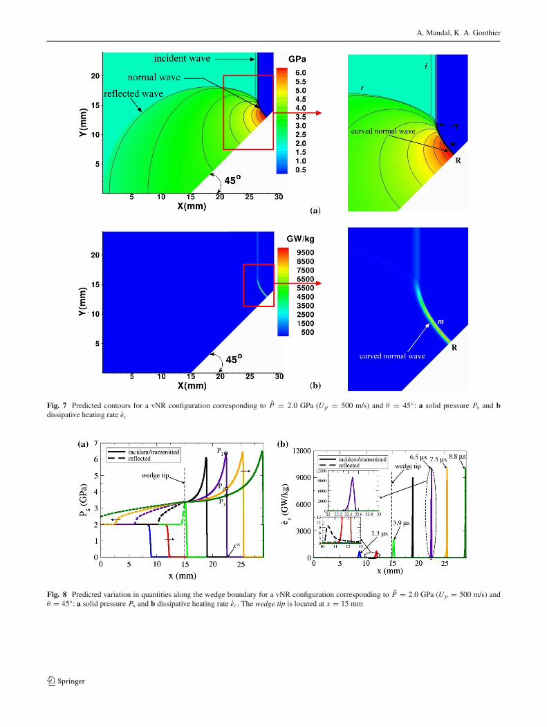
Fig. 7 Predicted contours for a vNR configuration corresponding to P = 2.0 GPa (Up = 500 m/s) and θ = 45◦: a solid pressure Ps and bdissipative heating rate ec
Fig. 8 Predicted variation in quantities along the wedge boundary for a vNR configuration corresponding to P = 2.0 GPa (Up = 500 m/s) andθ = 45◦: a solid pressure Ps and b dissipative heating rate ec. The wedge tip is located at x = 15 mm
123
Thermomechanics of transient oblique compaction shock reflection from a rigid boundary
d
dζ(ρsφw) = 0, (49)
d
dζ
(
ρsφw2 + Psφ)
= 0, (50)
d
dζ
(
E + Psρs
)
= 0, (51)
wdφ
dζ= φ (1 − φ)
μ(Ps − β) , (52)
wd˜φ
dζ= Λ, (53)
where
Λ ={ 1
μ
(
f (φ) − ˜φ)
if f (φ) > ˜φ,
0 otherwise.
Conditions at ζ = 0 in front of the shock correspond tothe stress-free ambient material state: φ(0) = ˜φ(0) = φ0,
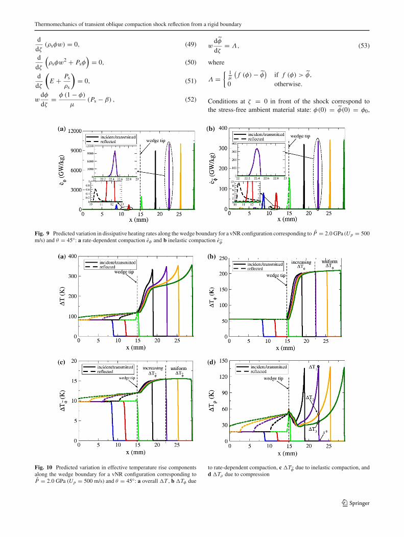
Fig. 9 Predicted variation in dissipative heating rates along the wedge boundary for a vNR configuration corresponding to P = 2.0 GPa (Up = 500m/s) and θ = 45◦: a rate-dependent compaction eφ and b inelastic compaction e
˜φ
Fig. 10 Predicted variation in effective temperature rise componentsalong the wedge boundary for a vNR configuration corresponding toP = 2.0 GPa (Up = 500 m/s) and θ = 45◦: a overall �T , b �Tφ due
to rate-dependent compaction, c �T˜φ due to inelastic compaction, and
d �Tρ due to compression
123
A. Mandal, K. A. Gonthier
Ps(0) = 0, ρs(0) = ρs0, w(0) = −D. The homogeneousODEs given by (49)–(51) can be directly integrated, with ini-tial conditions applied, and combined to obtain the followingexpressions after performing algebraic manipulations:
w = − (ρs0φ0D) / (ρsφ) , (54)
Ps =[
(ρs0φ0D)2(
1
ρs0φ0− 1
ρsφ
)]
/φ, (55)
es + B = 1
2Psφ
(
1
ρs0φ0− 1
ρsφ
)
. (56)
Equations (55) and (56) are the Rayleigh line R and Hugo-niot curveH for the granular solid. The initial-value problem(IVP) then reduces to numerically integrating (52) and (53)for shock profiles subject to (54)–(56), the constitutive rela-
tions contained in Appendix 1, and the initial conditionsφ(0) = ˜φ(0) = φ0. The numerical integration procedureis started by taking the initial value of the solid volume frac-tion to be φ∗ = φ0 + �φ, where �φ ≈ 10−6, which issufficient to perturb the solution off the ambient equilibriumstate. Compaction shock end states and the shock speed canbe directly determined by combining the equilibrium con-ditions Ps = β and ˜φ = φ0 for φ0 ≤ φ ≤ f −1(φ0), or˜φ = f (φ) for φ > f −1(φ0), with (54)–(56) and the con-stitutive relations. The effective ambient sound speed of thegranular material c0 can be obtained based on the tangencyrequirement ofR andH in the Psφ-ρsφ plane at the ambientstate.
Figure 6 illustrates the steady compaction shock profilesfor φ, ˜φ, and ec corresponding to φ0 = 0.85 and Up = 150,300, and 500m/s. Here, the shock profiles are plotted in terms
Fig. 11 Predicted contours for an SMR configuration corresponding to P = 2.0 GPa (Up = 500 m/s), and θ = 60◦: a solid pressure Ps and bdissipative heating rate ec
123

Thermomechanics of transient oblique compaction shock reflection from a rigid boundary
of the laboratory coordinate x . The effective sound speed forthis material is c0 = 506.34 � cs0 ≈ 2740 m/s, where cs0 isthe ambient sound speed of the solid. Corresponding shockspeeds D and incident Mach numbers Mi ≡ D/c0 are listedin Table 1. It is noted that the shock Mach numbers basedon cs0 are less than unity; therefore, shock profiles do notpossess a discontinuity in the solid. Following the terminol-ogy of Ref. [12], shock profiles have a viscoelastic precursorregion followed by a viscoplastic region in which substan-tial inelastic volumetric deformation occurs. The width ofthe viscoelastic region significantly decreases with increas-ing shock strength, as does the total shock width, which iseasily seen in the ec profiles. Stronger shocks result in morecompaction and significantly higher dissipative heating rates.
5 Results
The oblique interaction of steady compaction shocks withplanar boundaries are computationally examined in this sec-tion. The strength of the incident shock, which is a functionof Up and φ0, is characterized by its Mach number Mi andfinal equilibrium solid pressure P . Predictions are analyzedover the range 0◦ ≤ θ ≤ 90◦ for 0.73 ≤ φ0 ≤ 0.90. Domain
dimensions are chosen so that the length of the wedge bound-ary is L ≈ 20 mm for all values of θ . A grid resolutionof 40 grid points/mm is chosen based on the convergencestudy performed for steady compaction shock profiles. Rep-resentative predictions are first given that illustrate differentreflection configurations for φ0 = 0.85 and Up = 500 m/s,which result in an incident shock strength of Mi = 4.88 andP = 2.0 GPa, followed by predictions that establish theirexistence criteria in terms of θ and φ0.
5.1 Von Neumann reflection
Figure 7 illustrates the evolution of a vNR configuration forθ = 45◦. Predicted contours of Ps are shown in Fig. 7a whenthe interaction structure has nearly reached the far end of thedomain. The incident shock (i), reflected shock (r), and nor-mal shock (m) coexist within a triple point region (T ) of theinteraction structurewhich is indicative of an irregular reflec-tion (IR). Pressure contours are magnified in the vicinity ofthe boundary to highlight detailed features of the interac-tion structure. The normal shock is curved near point T andsmoothly merges with the incident shock from the reflec-tion point (R) on the boundary which is characteristic of avNR structure. The corresponding prediction for ec is givenin Fig. 7b. The incident and reflected shocks are not visible
Fig. 12 Predicted variation in solid pressure and compaction-induced dissipative heating rates along the wedge boundary for an SMR configurationcorresponding to P = 2.0 GPa (Up = 500 m/s) and θ = 60◦
123
A. Mandal, K. A. Gonthier
in this plot because their dissipative heating rates are smallcompared to that of the normal shock. Importantly, both Psand ec are maximum in the vicinity of the boundary; there-fore, we focus on the thermomechanical response of materiallocated within this region. Numerical experiments indicatethat artificial heating due to the shock-capturing techniquehas no discernible effect on predictions along the boundaryoutside the immediate vicinity of the wedge tip.
Predicted spatial and temporal variations in Ps and ec onthe lower computational boundary, both ahead of the wedgetip (x < 15 mm) and along its surface (x ≥ 15 mm), areshown in Fig. 8a, b, respectively, where x is the horizontaldistance measured from the left boundary of the computa-tional domain. Incident and transmitted shock predictionsare shown as solid lines, and reflected shock predictionsare shown as dashed lines. Time t = 0 µs correspondsto the initial position of the incident shock. Both the pres-sure and dissipative heating rate increase after the incidentshock encounters the wedge tip located at x = 15 mm. Aquasi-steady profile gradually evolves as the incident shockpropagates along the wedge boundary with peak values ofapproximately Ps = 6.5 GPa and ec = 10092.4 GW/kginduced by the normal shock which are substantially greaterthan those of the incident shock (Ps = 2.0 GPa and ec =742.3 GW/kg); the location of peak pressure corresponds to
the location of peak heating rate. The compaction heatingrate at t = 6.5 µs is magnified in the figure to high-light the normal shock structure which has a thickness ofδm ≈ 0.4 mm.
The relative importance of rate-dependent and inelasticcompaction on heating of thematerial is illustrated in Fig. 9a,b, respectively. Peak heating rates of eφ = 10092.4 GW/kgand e
˜φ = 341.9 GW/kg induced by the transmitted shockindicate that rate-dependent compaction is dominant alongthe wedge boundary. The reflected shock induces littleadditional dissipative heating, with peak values of ec =9.7 GW/kg, eφ = 0.6 GW/kg, and e
˜φ = 9.2 GW/kg.It is useful to integrate local dissipative heating rates over
the shock rise time to better establish the influence of ener-getic processes. To this end, the effective temperature risecomponents along the boundary, defined in (15), are shownin Fig. 10. Though the peak effective temperature rise behindthe incident shock is low, the peak value of �T = 356.0 Kbehind the normal shock is well above the approximate igni-tion temperature of HMX (Tig ≈ 600 K). Peak values of�Tφ = 210.8 K, �T
˜φ = 15.5 K, and �Tρ = 139.9 Kare predicted immediately behind the normal shock nearthe location of peak pressure. The dissipative temperaturerise monotonically increases, whereas the temperature riseinduced by compression decreases with the pressure behind
Fig. 13 Predicted variation in temperature rise components along the wedge boundary for an SMR configuration corresponding to P = 2.0 GPa(Up = 500 m/s) and θ = 60◦
123

Thermomechanics of transient oblique compaction shock reflection from a rigid boundary
the normal shock. The largest contributor to the effectivetemperature rise is rate-dependent dissipation. Though com-pression work is significant, it is unlikely to play a key rolein the ignition of energetic solids, because it affects substan-tially more mass than compaction-induced dissipation whichis localized near intergranular contact surfaces to form hotspots [27].
The peak temperature rise induced by the reflected shock(�T = 120.0 K) is much smaller than that of the trans-mitted shock (�T = 356.0 K). Rate-dependent dissipationminimally contributes to the effective temperature rise of thereflected shock, whereas inelastic compaction and compres-
sion induce temperature rise components of �T˜φ ≈ 2.0 K
and �Tρ ≈ 35.0 K. Because compression is the dominantheating mechanism, the reflected shock is unlikely to causeadditional hot-spot formation within the material precom-pacted by the incident shock. This observation is consistentwith a desensitization effect.
5.2 Simple Mach reflection
Figure 11 illustrates the evolution of an SMR configurationobtained by increasing thewedge angle to θ = 60◦. Predictedcontours of Ps and ec are shown in Fig. 11a, b. As with
Fig. 14 Predicted contours for an RR configuration corresponding to P = 2.0 GPa (Up = 500 m/s) and θ = 75◦: a solid pressure Ps and bdissipative heating rate ec
123
A. Mandal, K. A. Gonthier
a vNR configuration, the incident shock (i), reflected shock(r), and normal shock (m) coexist within a triple point regionT near the wedge boundary indicating that it is an irregularconfiguration. Moreover, the abrupt change in orientation ofthe largely planar normal shock relative to the incident shockwithin region T suggests a configuration that is analogous toan SMR.
Predicted variations in Ps and ec along the lower com-putational boundary are shown in Fig. 8a, b. Again, bothquantities increase along the wedge surface before obtainingquasi-steady profiles. The peak values of Ps = 12.1 GPa andec = 24748.8 GW/kg are induced by the strong shock stemwhich are substantially larger than those predicted for thevNR configuration.
Contributions to the dissipative heating rate by rate-dependent and inelastic compaction are shown in Fig. 12c, d.Peak values of eφ = 24748.8GW/kg and e
˜φ = 699.7GW/kgare predicted indicating that rate-dependent compaction isagain dominant. The reflected shock induces little additionalheating and has peak values of ec ≈ 36.0 GW/kg, eφ ≈6.0 GW/kg and e
˜φ ≈ 30.0 GW/kg. Inelastic compactionremains the dominant heating mechanism for the reflectedshock.
Predicted variations in effective temperature rise are givenin Fig. 13. All components achieve quasi-steady profiles
along the wedge surface having peak values of �T = 759.9K, �Tφ = 348.2 K, �T
˜φ = 21.8 K, and �Tρ = 397.6K. The peak solid temperature again exceeds the ignitiontemperature of HMX. Though compression is the domi-nant heating mechanism for this configuration, compactionis again more likely to initiate combustion by hot-spot for-mation. Peak temperature rises of �T
˜φ ≈ 3.0 K and �Tρ ≈59.0 K are induced by the reflected shock near the wedge tipin the material precompacted by the incident shock. Rate-dependent dissipation is again inconsequential.
5.3 Regular reflection
Figure 14 illustrates the evolution of an RR configurationobtained by further increasing the wedge angle to θ = 75◦.The predicted contours of Ps and ec are given in Fig. 14. Forthis configuration, the incident shock directly reflects off thewedge surface at point R producing a reflected shock at thatlocation. The reflected shock is sufficiently strong to turnthe flow parallel to the wedge surface without the presenceof a shock stem. The large, high-pressure region behind thereflected shock, referred to as the “plateau region,” is analo-gous to a uniform supersonic zone observed in RR configura-tions for gases involving oblique shock reflections [3,8]. This
Fig. 15 Predicted variation in solid pressure and compaction-induced dissipative heating rates along the wedge boundary for an RR configurationcorresponding to P = 2.0 GPa (Up = 500 m/s) and θ = 75◦
123
Thermomechanics of transient oblique compaction shock reflection from a rigid boundary
region isolates the reflection point from corner-generated dis-turbances, thereby maintaining its integrity.
Predicted profiles for Ps and ec, shown in Fig. 15, quicklybecome quasi-steady along the wedge surface. Unlike gasdynamics, the plateau region identified in themagnified pres-sure plot is spatially non-uniform due to the finite thicknessof resolved compaction shocks. The peak values Ps = 7.84GPa and ec = 2727.41 GW/kg are substantially lower thanthose of the SMR configuration due to the absence of a shockstem.
Rate-dependent dissipation is again dominant across thetransmitted shock as indicated by the peak values eφ =2577.5 GW/kg and e
˜φ = 305.3 GW/kg, and inelastic com-paction is dominant across the reflected shock as indicatedby the values ec = 150.1 GW/kg, eφ = 50.2 GW/kg ande˜φ = 100.6 GW/kg. The latter values are larger than thosecorresponding to reflected shocks in the vNR and SMR con-figurations. Rate-dependent heating induced by the reflectedshock is significantly smaller than that of the incident shockin this case, whereas inelastic heating is comparable.
As illustrated in Fig. 16, a peak effective temperature riseof �T = 298.34 K is predicted along the wedge surfacenear the location of peak dissipative heating. Contrary tovNR and SMR configurations, the compaction-induced tem-
perature rise increases more slowly along the wedge surfacethan that of compression. Peak values of �Tφ = 117.13K, �T
˜φ = 15.42 K, and �Tρ = 171.2 K indicate thatcompression is the dominant heating mechanism, thoughrate-dependent dissipation is also significant. The reflectedshock induces an effective temperature rise of �T ≈ 90 K,most of which results from compression (�Tρ ≈ 85 K).
5.4 Dependence on deflection angle: a summary
Peak values of pressure and dissipative heating rates alongthe wedge surface are summarized in Fig. 17 for 0◦ ≤ θ ≤90◦, where θ is increased in increments of �θ = 5◦. Allpredictions correspond to φ0 = 0.85 andUp = 500 m/s. Thevalue θ = 0◦ is associated with complete transmission of theincident shock, and θ = 90◦ is associated with completereflection.
A continuous transition between reflection configurationsis predicted with increasing wedge angle. Transition bound-aries are difficult to precisely define based on simulations,but are approximately given by the following: vNR con-figurations exist for 0◦ < θ ≤ 50◦, SMR configurationsexist for 50◦ < θ ≤ 68◦, and RR configurations exist for68◦ < θ < 90◦. Peak values of pressure and heating rate
Fig. 16 Predicted variation in temperature rise components along the wedge boundary for an SMR configuration corresponding to P = 2.0 GPa(Up = 500 m/s) and θ = 75◦
123

A. Mandal, K. A. Gonthier
Fig. 17 Predicted variation in peak quantities associated with quasi-steady profiles along the wedge boundary with deflection angle θ for P = 2.0GPa (Up = 500 m/s)
(including the effective temperature rise components whichare not shown for brevity) initially increase with θ as theflow transitions from vNR to SMR configurations until max-imum values are obtained for a critical deflection angle ofθc ≈ 60◦. The increase in rate-dependent compaction heat-ing results from strengthening of the shock stem along thewedge surface. A decrease in all peak values occurs as θ
further increases due to weakening of the shock stem as theflow transitions to RR configurations. Peak values associ-atedwithRR configurations are caused by the reflected shocknear the wedge surface, though these shocks are significantlyweaker than SMR shock stems. compaction-induced heatingis smallest behind reflected planar shocks corresponding toθ = 90◦, as nearly all porosity is eliminated by the incidentshock.
5.5 Dependence on initial packing density
It is well established that the initial density of porous explo-sives, prescribed by φ0, can significantly affect their heatingand combustion response [31]. Predictions are given in thissection that illustrate how φ0 affects reflection configurationsand heating for Up = 500 m/s; qualitatively similar predic-tions are obtained for other values ofUp . Because the incident
shock strength depends on bothUp and φ0, its Mach numberMi and pressure P are not constant. Here, φ0 is varied overthe range 0.73 ≤ φ0 ≤ 0.90 which encompasses the densityof many pressed explosives used in practice. This range ofφ0, respectively, corresponds to a range of incident Machnumbers given by 4.01 ≤ Mi ≤ 5.25.
Predicted variations in peak pressure and heating ratesalong the wedge surface for 0◦ ≤ θ ≤ 90◦ are given inFig. 18 for materials having φ0 = 0.73, 0.80, 0.85, and0.90; corresponding variations in peak temperature rises aregiven in Fig. 19. For each material, transition between reflec-tion configurations with increasing θ is qualitatively similarto that already discussed, but the peak pressure, heatingrates, temperature rises, and transition and critical deflec-tion angles depend on φ0. As φ0 increases, shock speedsincrease with corresponding increases in peak pressure andcompaction-induced heating rates along the wedge surface,as seen in Fig. 18. Larger relative changes are associatedwith peak pressure and inelastic heating rate, though thisrate is energetically less consequential than rate-dependentcompaction. Transition between reflection configurations isaccelerated by higher density because of the higher incidentshock strength. Thus, the critical deflection angle indicatingthe onset of RR configurations decreases with increasing φ0.
123

Thermomechanics of transient oblique compaction shock reflection from a rigid boundary
Fig. 18 Predicted variation in peak solid pressure and compaction-induced dissipative heating rates associated with quasi-steady profiles alongthe wedge boundary with initial solid volume fraction φ0 and deflection angle θ for Up = 500 m/s
Approximate values of θc = 65◦ and 60◦ are predicted forφ0 = 0.73 and 0.90, respectively. The compaction heatingrate ec is dominated by rate-dependent compaction for allvalues of φ0 and θ .
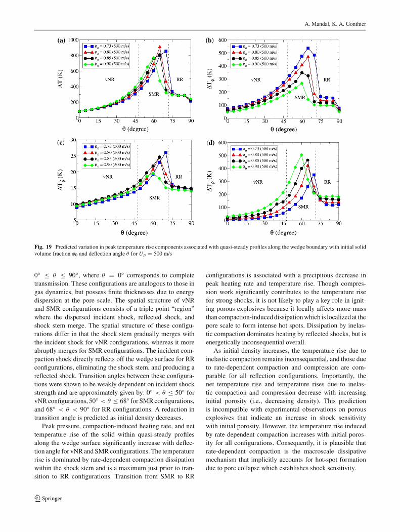
The variation in effective temperature rise with φ0, givenin Fig. 19, indicates a subtle but interesting result. Thetemperature rise due to inelastic compaction is largely incon-sequential, and those due to rate-dependent compaction andcompression are comparable. Although the heating rate byrate-dependent compaction increases with φ0, its integratedvalue across shock profiles results in higher temperature risesfor materials having lower density over the entire range ofθ . This trend, which is opposite to that predicted for thenet effective temperature rise, and the effective temperaturerises due to inelastic compaction and compression, is com-patible with experimental observations on shock sensitivityof porous explosives. Therefore, rate-dependent compactionlikely represents the macroscale dissipative mechanism thatimplicitly accounts for hot-spot formation during pore col-lapse. Dissipative work associated with this mechanism(which is proportional to �Tφ) can form a basis for devel-oping hot spot-motivated burn models for these materials.To this end, it is necessary to develop physically motivatedstrategies for localizing the effective dissipative work at thepore scale to estimate hot-spot temperatures (such as done
in Ref. [11]). This result underscores the need to carefullyexamine and interpret the isolated effects of different heatingmechanisms within shocks to establish their relative impor-tance.
6 Conclusions
Transient oblique reflection of compaction shocks from rigidplanar boundaries was computationally examined as a firststep in characterizing the thermomechanics of compactionshock propagation in complex domains. The model accountsfor dissipative heating within the solid by rate-dependent andinelastic compaction and reversible heating by compression.Emphasis was placed on examining reflection configurationsfor resolved, spatially dispersed shocks that are analogous tothose given by gas dynamics, and on identifying the relativeimportance of heating mechanisms and their dependence onshock deflection angle and initial material density.
Incident shock strength depends on the shock particlevelocity, as prescribed by the speed of a supporting pis-ton, and the initial material density. For fixed incident shockstrength, a transition from von Neumann (vNR) to simpleMach (SMR) to regular (RR) reflection configurations waspredicted with increasing deflection angle over the range
123
A. Mandal, K. A. Gonthier
Fig. 19 Predicted variation in peak temperature rise components associated with quasi-steady profiles along the wedge boundary with initial solidvolume fraction φ0 and deflection angle θ for Up = 500 m/s
0◦ ≤ θ ≤ 90◦, where θ = 0◦ corresponds to completetransmission. These configurations are analogous to those ingas dynamics, but possess finite thicknesses due to energydispersion at the pore scale. The spatial structure of vNRand SMR configurations consists of a triple point “region”where the dispersed incident shock, reflected shock, andshock stem merge. The spatial structure of these configu-rations differ in that the shock stem gradually merges withthe incident shock for vNR configurations, whereas it moreabruptly merges for SMR configurations. The incident com-paction shock directly reflects off the wedge surface for RRconfigurations, eliminating the shock stem, and producing areflected shock. Transition angles between these configura-tions were shown to be weakly dependent on incident shockstrength and are approximately given by: 0◦ < θ ≤ 50◦ forvNRconfigurations, 50◦ < θ ≤ 68◦ for SMRconfigurations,and 68◦ < θ < 90◦ for RR configurations. A reduction intransition angle is predicted as initial density decreases.
Peak pressure, compaction-induced heating rate, and nettemperature rise of the solid within quasi-steady profilesalong the wedge surface significantly increase with deflec-tion angle for vNRandSMRconfigurations. The temperaturerise is dominated by rate-dependent compaction dissipationwithin the shock stem and is a maximum just prior to tran-sition to RR configurations. Transition from SMR to RR
configurations is associated with a precipitous decrease inpeak heating rate and temperature rise. Though compres-sion work significantly contributes to the temperature risefor strong shocks, it is not likely to play a key role in ignit-ing porous explosives because it locally affects more massthan compaction-induceddissipationwhich is localized at thepore scale to form intense hot spots. Dissipation by inelas-tic compaction dominates heating by reflected shocks, but isenergetically inconsequential overall.
As initial density increases, the temperature rise due toinelastic compaction remains inconsequential, and those dueto rate-dependent compaction and compression are com-parable for all reflection configurations. Importantly, thenet temperature rise and temperature rises due to inelas-tic compaction and compression decrease with increasinginitial porosity (i.e., decreasing density). This predictionis incompatible with experimental observations on porousexplosives that indicate an increase in shock sensitivitywith initial porosity. However, the temperature rise inducedby rate-dependent compaction increases with initial poros-ity for all configurations. Consequently, it is plausible thatrate-dependent compaction is the macroscale dissipativemechanism that implicitly accounts for hot-spot formationdue to pore collapse which establishes shock sensitivity.
123
Thermomechanics of transient oblique compaction shock reflection from a rigid boundary
Mesoscale modeling and simulation (M&S) is beingused to examine the evolution of thermomechanical fluctua-tions within and behind compaction shocks and the relativeimportance of dissipation mechanisms, their dependence onmicrostructure and loading conditions, and their influenceon macroscale behavior [24,27]. In addition to enhanc-ing the fundamental understanding of such phenomena,this information is useful in guiding the development ofmicrostructure-dependent theories for shock-induced igni-tion and combustion of these materials at the macroscale.Moreover, it is often tacitly assumed that mesoscale M&Sapplied to thesematerials gives effective (filtered) predictionsthat are compatible with commonly used macroscale theo-ries, though it is not often rigorously examined, particularlyas it pertains to compaction shocks in granular explosives.The authors are currently examining the extent to whichmesoscale predictions of compaction shock profiles agreewith those given by the macroscale theory described in thispaper [15,29]. To this end, it is possible to establish correla-tions between effective dissipative compaction work (givenby �Tφ/cv) and hot spots, both of which vary with shockstrength and microstructure. These correlations may be usedto formulate hot spot-motivated ignition and burn models toaccurately describe complex phenomena involving detona-tion initiation and failure of low-density granular explosives.
Acknowledgments The authors gratefully acknowledge funding forthis work provided by the U.S. Air Force Office of Scientific Research(AFOSR) under Contract Number FA9550-06-1-0121 and the U.S. AirForceResearchLaboratory (AFRL-MNME), EglinAFB, Florida, underContract Number FA8651-06-1-0005. Portions of this research wereconducted with high-performance computational resources providedby Louisiana State University (http://www.hpc.lsu.edu).
Appendix: Constitutive relations for granularHMX
Constitutive relations used in this study describe the statebehavior of the solid component HMX and the compactionbehavior of granular HMX.
A Mie-Grüneisen equation of state is used to describe thethermodynamics:
Ps = PH + Γ
νs0(es − eH ) , (57)
where νs0 = 1/ρs0 is the initial mass-specific volume andΓ is a constant Grüneisen coefficient. The functions PH (νs)
and eH (νs) are defined by
PH ≡[
ω
νs0 − s (νs0 − νs)
]2
(νs0 − νs) ,
eH ≡ 1
2
[
ω (νs0 − νs)
νs0 − s (νs0 − νs)
]2
, (58)
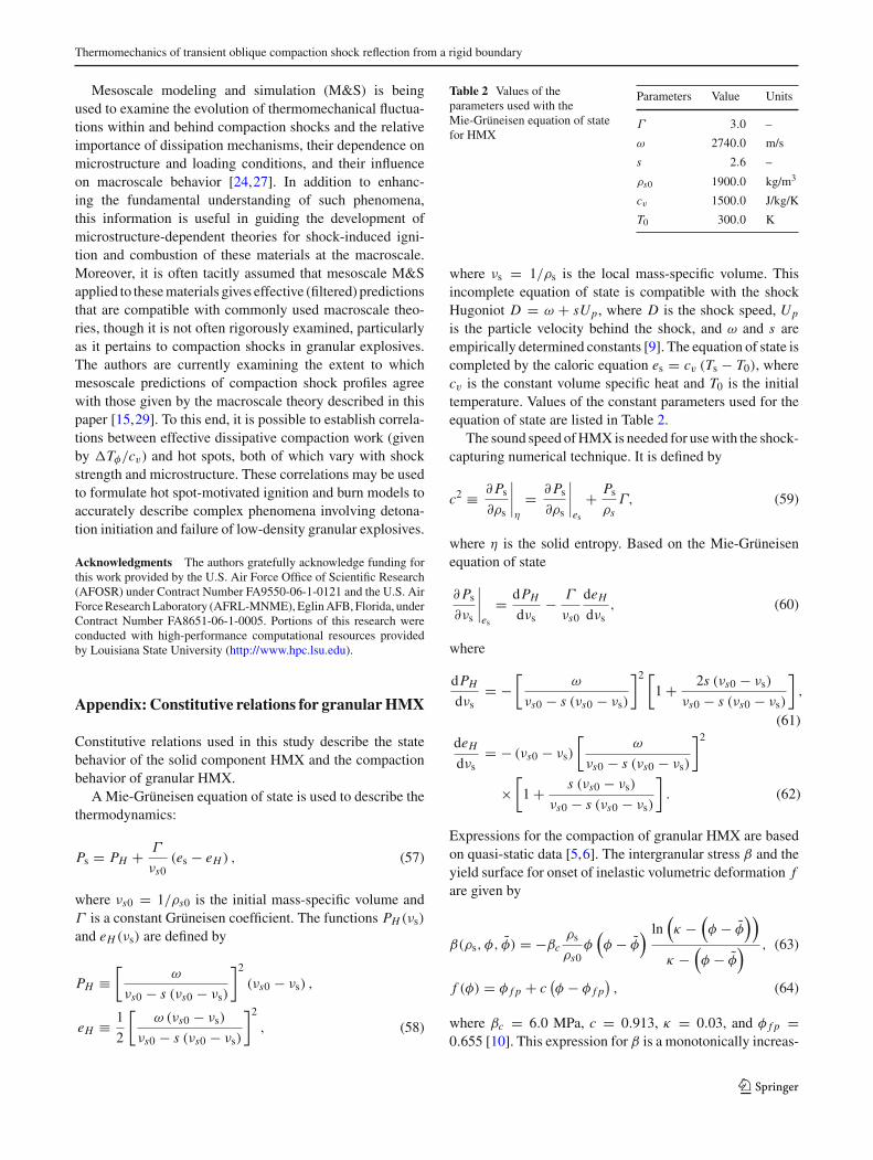
Table 2 Values of theparameters used with theMie-Grüneisen equation of statefor HMX
Parameters Value Units
Γ 3.0 –
ω 2740.0 m/s
s 2.6 –
ρs0 1900.0 kg/m3
cv 1500.0 J/kg/K
T0 300.0 K
where νs = 1/ρs is the local mass-specific volume. Thisincomplete equation of state is compatible with the shockHugoniot D = ω + sUp, where D is the shock speed, Up
is the particle velocity behind the shock, and ω and s areempirically determined constants [9]. The equation of state iscompleted by the caloric equation es = cv (Ts − T0), wherecv is the constant volume specific heat and T0 is the initialtemperature. Values of the constant parameters used for theequation of state are listed in Table 2.
The sound speed ofHMX is needed for usewith the shock-capturing numerical technique. It is defined by
c2 ≡ ∂Ps∂ρs
∣
∣
∣
∣
η
= ∂Ps∂ρs
∣
∣
∣
∣
es
+ Psρs
Γ, (59)
where η is the solid entropy. Based on the Mie-Grüneisenequation of state
∂Ps∂νs
∣
∣
∣
∣
es
= dPH
dνs− Γ
νs0
deHdνs
, (60)
where
dPH
dνs= −
[
ω
νs0 − s (νs0 − νs)
]2 [
1 + 2s (νs0 − νs)
νs0 − s (νs0 − νs)
]
,
(61)
deHdνs
= − (νs0 − νs)
[
ω
νs0 − s (νs0 − νs)
]2
×[
1 + s (νs0 − νs)
νs0 − s (νs0 − νs)
]
. (62)
Expressions for the compaction of granular HMX are basedon quasi-static data [5,6]. The intergranular stress β and theyield surface for onset of inelastic volumetric deformation fare given by
β(ρs, φ, φ) = −βcρs
ρs0φ
(
φ − φ) ln
(
κ −(
φ − φ))
κ −(
φ − φ) , (63)
f (φ) = φ f p + c(
φ − φ f p)
, (64)
where βc = 6.0 MPa, c = 0.913, κ = 0.03, and φ f p =0.655 [10]. This expression for β is a monotonically increas-
123
A. Mandal, K. A. Gonthier
ing functionof the elastic component of volume fractionφ−φ
and contains a linear dependence on solid density as requiredby thermodynamic constraints [14]. The expression for f isa monotonically increasing function of φ which is indicativeof work hardening. Using (63), the following expression for
the compaction potential energy B = ∫ (φ−φ)
0β
ρsφd(φ − φ)
is obtained:
B(φ − φ) = βc
ρs0
{
κ
2
[
(
ln(
κ −(
φ − φ)))2 − (ln κ)2
]
−(
κ −(
φ − φ))
×[
ln(
κ −(
φ − φ))
− 1]
+ κ (ln κ − 1)
}
.
(65)
References
1. Baer, M.R., Nunziato, J.W.: A two-phase mixture theory for thedeflagration-to-detonation transition (DDT) in reactive granularmaterials. Int. J. Multiph. Flow 12(6), 861–889 (1986)
2. Bdzil, J.B., Menikoff, R., Son, S.F., Kapila, A.K., Stewart, D.S.:Two-phase modeling of deflagration-to-detonation transition ingranular materials: a critical examination of modeling issues. Phys.Fluids 11(2), 378–402 (1999)
3. Ben-Dor, G.: ShockWave Reflection Phenomena. Springer, Berlin(2007)
4. Brown, B.P., Argrow, B.M.: Two-dimensional shock tube flow fordense gases. J. Fluid Mech. 349, 95–115 (1997)
5. Coyne, P.J. Jr., Elban,W.L.,Chiarito,M.A.: The strain rate behaviorof coarse HMX porous bed compaction. In: Eighth InternationalDetonation Symposium, pp. 645–657 (1989)
6. Elban, W.L., Chiarito, M.A.: Quasi-Static compaction study ofcoarse HMX explosive. Powder Technol. 46, 181–193 (1986)
7. Field, J.E., Palmer, S.J.P., Pope, P.H., Sundararajan, R., Swallowe,G.M.: Mechanical properties of PBX’s and their behavior duringdrop-weight impact. In: Proceedings of Eighth International Sym-posium on Detonation, pp. 635–644 (1985)
8. Glaz, H.M., Colella, P., Glass, I.I., Deschambault, R.L.: A numer-ical study of oblique shock-wave reflections with experimentalcomparisons. Proc. R. Soc. Lond. Ser. A 398(1814), 117–140(1985)
9. Gibbs, T.R., Popolato, A.: LASL Explosive Property Data. Univer-sity of California Press, Berkeley (1980)
10. Gonthier, K.A., Menikoff, R., Son, S.F., Asay, B.W.: Modelingcompaction induced energy dissipation of granular HMX. In: Pro-ceedings of the 11th Detonation Symposium, pp. 153–161 (1998)
11. Gonthier, K.A.: Modeling and analysis of reactive compaction forgranular energetic solids. Combust. Sci. Technol. 175, 1679–1709(2003)
12. Gonthier, K.A.: Predictions for weak mechanical ignition of strainhardened granular explosive. J. Appl. Phys. 95(7), 3482–3494(2004)
13. Gonthier, K.A., Jogi, V.: Multiscale shock heating analysis of agranular explosive. J. Appl. Mech. 76(4), 538–552 (2005)
14. Gonthier, K.A., Cox, C.F.: Predictions for the impact of a granularsolid having spatially non-uniform bulk porosity. Comput. Mech.39, 419–437 (2007)
15. Gonthier, K.A., Chakravarthy, S.: Shock induced ignition of porousHMX—a computational examination of hot-spot formation rates.In: Proceedings of the 15th International Detonation Symposium,13–18 July, San Francisco, to appear (2014)
16. Heavens, S.N., Fields, J.E.: The ignition of a thin layer of explosiveby impact. Proc. R. Soc. Lond. Ser. A 338, 77–93 (1974)
17. Hornung, H.G., Oertel Jr, H., Sandeman, R.J.: Transition to machreflection of shock waves in steady and pseudo-steady flows withand without relaxation. J. Fluid Mech. 90, 541–560 (1979)
18. Keshavarz, M.H., Pouretedal, H.R.: Simple empirical method forprediction of impact sensitivity of selected class of explosives. J.Hazard. Mater. 124, 27–33 (2005)
19. Kimura, E., Oyumi, Y.: Sensitivity of solid rocket propellants forcard gap test. Propellants Explos. Pyrotech. 24, 90–94 (1999)
20. Krishna Mohan, V., Jyothi Bhasu, V.C., Field, J.E.: Role of adia-batic shear bands in initiation of explosives by drop-weight impact.In: Proceedings of Ninth International Symposium on Detonation,pp. 1276–1283 (1989)
21. Kurganov,A., Tadmor, E.: Newhigh-resolution central schemes fornonlinear conservation laws and convection-diffusion equations. J.Comput. Phys. 160, 241–282 (2000)
22. Licht, H.H.: Performance and sensitivity of explosives. PropellantsExplos. Pyrotech. 25, 126–132 (2000)
23. Macek, A.: Sensitivity of explosives. Chem. Rev. 62, 41–63 (1962)24. Mandal, A.: Computational examination of compaction wave-
boundary interaction in granular explosive. Thesis, Louisiana StateUniversity, Baton Rouge, Louisiana (2010) (http://etd.lsu.edu/docs/available/etd-08112010-163505)
25. McAfee, J.M., Asay, B.W., Campbell, W., Ramsay, J.B.: Deflagra-tion to detonation transition in granular HMX. In: Proceedings ofthe Ninth International Symposium on Detonation, pp. 265–278(1989)
26. McAfee, J.M.: Characterization of high-explosive initiation andsafety at Los Alamos. Los Alamos National Laboratory TechnicalReport, LA-UR-94-3316 (1994)
27. Panchadhar, R., Gonthier, K.A.: Mesoscale analysis of volumetricand surface dissipation in granular explosive induced by uniaxialdeformation waves. Shock Waves 21(1), 43–61 (2010)
28. Powers, J.M., Stewart, D.S., Krier, H.: Analysis of steady com-pactionwaves in porousmaterials. J. Appl.Mech. 56, 15–24 (1989)
29. Rao, P., Gonthier, K.A.: Reactive burn modeling of porous solidexplosives. American Institute of Aeronautics and AstronauticsPaper AIAA 2014-2810. Presented at the AIAA Propulsion andEnergy Forum and Exposition, Cleveland, Ohio, 28–30 July (2014)
30. Sandusky, H.W., Liddiard, T.P.: Dynamic compaction of porousbeds. NSWC TR 83-246, Naval Surface Weapons Center (1985)
31. Sheffield, S.A., Gustavsen, R.L., Anderson, M.U.: Shock Loadingof Porous High Explosives. High-Pressure Shock Compression ofSolids, vol. IV, pp. 24–61. Springer-Verlag, New York (1997)
32. Shu, C.W., Osher, S.: Efficient implementation of essentially non-oscillatory shock-capturing schemes. J. Comput. Phys. 77, 439–471 (1988)
33. Strang, G.: On the construction and comparison of differenceschemes. SIAM J. Numer. Anal. 5(3), 506–517 (1968)
34. Walley, S.M., Field, J.E., Palmer, S.J.P.: Impact sensitivity of pro-pellants. Proc. Math. Phys. Sci. 438(1904), 571–583 (1992)
35. Wilson, W.H., Tasker, D.G., Dick, R.D., Lee, R.J.: Initiation ofexplosives under high deformation loading conditions. In: Pro-ceedings of the Eleventh Detonation (International) Symposium,pp. 565–572. Snowmass (1998)
36. Woodward, P., Colella, P.: The numerical simulation of two-dimensional fluid flow with strong shocks. J. Comput. Phys. 54,115–173 (1984)
123