Managing The Interstitials - 20173
23
Managing the Interstitials, a System of Systems Framework Suited for the Ballistic Missile Defense System Robert K. Garrett, Jr., 1,* Steve Anderson, 2 Neil T. Baron, 3 and James D. Moreland, Jr. 4,† 1 Naval Surface Warfare Center, Dahlgren Division (NSWCDD), 6138 Norc Avenue, Building 221, Suite 314, Dahlgren, VA 22448- 5157 2 Naval Surface Warfare Center, Dahlgren Division (NSWCDD), 17214 Avenue B, Building 1500, Suite 124, Dahlgren, VA 22448- 5157 3 Naval Surface Warfare Center, Dahlgren Division (NSWCDD), 19008 Wayside Drive, Building 1490, Dahlgren, VA 22448-5157 4 Naval Surface Warfare Center, Dahlgren Division (NSWCDD), 17214 Avenue B, Building 1500, Dahlgren, VA 22448-5157 A SYSTEM OF SYSTEMS FRAMEWORK BALLISTIC MISSILE DEFENSE Received 11 August 2009; Revised 4 March 2010; Accepted 10 June 2010, after one or more revisions Published online in Wiley Online Library (wileyonlinelibrary.com) DOI 10.1002/sys.20173 ABSTRACT Recent engineering experiences with the Missile Defense Agency (MDA) Ballistic Missile Defense System (BMDS) highlight the need to analyze the BMDS System of Systems (SoS) including the numerous potential interactions between independently developed elements of the system. The term “interstitials” is used to define the domain of interfaces, interoperability, and integration between constituent systems in an SoS. The authors feel that this domain, at an SoS level, has received insufficient attention within systems engineering literature. The BMDS represents a challenging SoS case study as many of its initial elements were assembled from existing programs of record. The elements tend to perform as designed but their performance measures may not be consistent with the higher level SoS requirements. One of the BMDS challenges is interoperability, to focus the independent elements to interact in a number of ways, either subtle or overt, for a predictable and sustainable national capability. New capabilities desired by national leadership may involve modifications to kill chains, Command and Control (C2) constructs, improved coordination, and performance. These capabilities must be realized through modifications to programs of record and integration across elements of the system that have their own independent programmatic momentum. A challenge of SoS Engineering is to objectively evaluate competing solutions and assess the technical viability of tradeoff options. This paper will present a multifaceted technical approach for integrating a complex, adaptive SoS to achieve a functional capability. Architectural frame- works will be explored, a mathematical technique utilizing graph theory will be introduced, adjuncts to more traditional modeling and simulation techniques such as agent based modeling will be explored, and, finally, newly developed technical and managerial metrics to describe design maturity will be introduced. A theater BMDS construct will be used as a representative set of elements together with the *Author to whom all correspondence should be addressed (e-mail: [email protected]; [email protected]; [email protected]; [email protected]). † Commanding Officer, 6149 Welsh Road, Suite 203, Dahlgren, VA 22448-5130 Systems Engineering © 2010 Wiley Periodicals, Inc. 1 Regular Paper
-
Upload
bob-garrett -
Category
Documents
-
view
58 -
download
2
Transcript of Managing The Interstitials - 20173
Managing the Interstitials, a System ofSystems Framework Suited for the BallisticMissile Defense SystemRobert K. Garrett, Jr.,1,* Steve Anderson,2 Neil T. Baron,3 and James D. Moreland, Jr.4,†
1Naval Surface Warfare Center, Dahlgren Division (NSWCDD), 6138 Norc Avenue, Building 221, Suite 314, Dahlgren, VA 22448-51572Naval Surface Warfare Center, Dahlgren Division (NSWCDD), 17214 Avenue B, Building 1500, Suite 124, Dahlgren, VA 22448-51573Naval Surface Warfare Center, Dahlgren Division (NSWCDD), 19008 Wayside Drive, Building 1490, Dahlgren, VA 22448-51574Naval Surface Warfare Center, Dahlgren Division (NSWCDD), 17214 Avenue B, Building 1500, Dahlgren, VA 22448-5157
A SYSTEM OF SYSTEMS FRAMEWORK BALLISTIC MISSILE DEFENSE
Received 11 August 2009; Revised 4 March 2010; Accepted 10 June 2010, after one or more revisionsPublished online in Wiley Online Library (wileyonlinelibrary.com) DOI 10.1002/sys.20173
ABSTRACT
Recent engineering experiences with the Missile Defense Agency (MDA) Ballistic Missile Defense System(BMDS) highlight the need to analyze the BMDS System of Systems (SoS) including the numerouspotential interactions between independently developed elements of the system. The term “interstitials”is used to define the domain of interfaces, interoperability, and integration between constituent systemsin an SoS. The authors feel that this domain, at an SoS level, has received insufficient attention withinsystems engineering literature. The BMDS represents a challenging SoS case study as many of its initialelements were assembled from existing programs of record. The elements tend to perform as designedbut their performance measures may not be consistent with the higher level SoS requirements. One ofthe BMDS challenges is interoperability, to focus the independent elements to interact in a number ofways, either subtle or overt, for a predictable and sustainable national capability. New capabilities desiredby national leadership may involve modifications to kill chains, Command and Control (C2) constructs,improved coordination, and performance. These capabilities must be realized through modifications toprograms of record and integration across elements of the system that have their own independentprogrammatic momentum. A challenge of SoS Engineering is to objectively evaluate competing solutionsand assess the technical viability of tradeoff options. This paper will present a multifaceted technicalapproach for integrating a complex, adaptive SoS to achieve a functional capability. Architectural frame-works will be explored, a mathematical technique utilizing graph theory will be introduced, adjuncts tomore traditional modeling and simulation techniques such as agent based modeling will be explored,and, finally, newly developed technical and managerial metrics to describe design maturity will beintroduced. A theater BMDS construct will be used as a representative set of elements together with the
*Author to whom all correspondence should be addressed (e-mail: [email protected]; [email protected];[email protected]; [email protected]).†Commanding Officer, 6149 Welsh Road, Suite 203, Dahlgren, VA 22448-5130
Systems Engineering© 2010 Wiley Periodicals, Inc.
1
Regular Paper
interstitials representing the integration domain. Increased attention to the interstitial space of theoverarching BMDS SoS construct and applying appropriate technical rigor and engineering due diligencewith these added tools should greatly assist the BMDS in realizing its potential. © 2010 Wiley Periodicals,Inc. Syst Eng
Key words: System of Systems; complexity; Ballistic Missile Defense; architecture; modeling and simula-tion
1. INTRODUCTION
This paper, as written by naval defense engineering practitio-ners, is an attempt at outreach to the larger academic andindustrial engineering community. The challenges in design-ing and realizing very large scale technological machines ofwar, with a U.S. Navy Aegis destroyer, an Aircraft Carrier,and a multiservice National Ballistic Missile Defense capa-bility being just a few examples, have been daunting to thepublic and private defense industrial base as evidenced inexcessive cost overruns and schedule breaches of ongoingprograms. The vision of our political leaders is not beingrealized by the technical community within agreeable budgetand schedule constraints. Large-scale warfare system devel-opment can take a decade or more to realize, a timeline thatis often compounded by the dynamic needs of national de-fense. We attempt in this paper to encourage investigation ofthe potential utility of new perspectives, approaches, and toolsfor the systems engineer. We believe that the concepts pre-sented here will equip the systems engineer to better under-stand and manage system complexity while engaged in thedesign cycle as well as enhance the engineer’s ability tocommunicate critical design attributes that drive the perform-ance of such systems. We suggest that the rich intellectual basealready existing in areas such as network flow analysis andsystem dynamics can be combined with new computationalapproaches such as agent-based modeling to augment tradi-tional systems engineering. We hope to encourage technicaldiscussion and debate on the development, use, and utility ofsuch tools with respect to the engineering of large scalecomplex systems of systems for naval defense.
A theater BMDS is an example of a highly complex,adaptive SoS that can be represented at any time using net-work flow nomenclature. As such, individual systems can berepresented as nodes and the interactions between them byedges. Using this graph theoretic approach offers an extensivebody of mathematical theory along with analysis methods thatallow the SoS to be analyzed in a coherent and comprehensivemanner. In practice, a BMDS SoS can be characterized by aloosely coupled federation based on the local threat andavailable assets. A key characteristic of any BMDS SoS is thedistributed Command and Control (C2) structure with com-plex technical demands such as real-time fire control andcontrasting non-real-time planning and situational awareness.The constituent systems tend to be well understood and rep-resented by mature dynamic systems analysis, i.e., SystemDynamics (SD). Historically, each constituent shooter systembrings its own organic fire control system to the SoS. Inte-grated fire control can be limited by the queuing of inde-
pendent sensors. If the theater BMDS/SoS were able to suc-cessfully integrate fire control across all available land, sea,and space-based sensors, the resulting capability should haveimproved discrimination timelines to facilitate warfightingconstructs such as Engage on Remote (EoR) and Launch onRemote (LoR) doctrine to improve the theater BMDS prob-ability of raid annihilation. EoR is a distributed engagementconstruct wherein the shooter system receives sensor inputsolely from nonorganic sensors of sufficient quality to supportall phases of the ballistic missile engagement sequence. Guid-ance updates to the interceptor are based solely on this nonor-ganic sensor track. LoR is a similar distributed engagementwherein the shooter receives sensor input from off-boardsensors of sufficient quality to launch an interceptor andsupport flight operations until the shooter establishes its ownorganic track of the target. The term organic is defined as theitems assigned to and forming an essential part of a militaryorganization [DoD, 2001] or more simply as an example, aradar or missile launcher mounted on a specific ship. Fre-quently, nonorganic components are developed inde-pendently of the shooter system, usually by another programoffice using different systems engineering processes, tools,and techniques which presents integration challenges. In otherwords, we are entering a new era that requires the dynamicintegration of distributed detect, distributed control, and dis-tributed engage features comprised of heterogeneous compo-nents.
This paper will present a multi-faceted technical approachfor integrating a complex, adaptive SoS to achieve a func-tional capability. The theater BMDS construct will be used asan example of a highly complex, highly integrated SoS tohighlight the importance and dependency of the integrationdomain, i.e., interstitial space, between elements of the SoS.A means to represent the elements and the interstitial spacewill be proposed with a mathematical analogy. The method-ology proposed should assist in better understanding SoScomplexity. In addition to the appropriate use of traditionalSD, Agent-Based Modeling (ABM) is suggested as a tech-nique to explore and quantify the interstitial behaviors. Thenascent concepts of Integration Readiness Level (IRL), Sys-tem Readiness Level (SRL), and Enterprise Readiness Level(ERL) will be described. We suggest that these concepts,when considered in combination with the traditional Technol-ogy Readiness Level (TRL), provide an initial subjectivemetric to guide SoS integration and to quantify the notion ofSoS “maturity.”
This paper is one in a series of papers [Zilic and Baron,2009; Moreland, 2009; Ormsby, 2008] developed by theNaval Warfare Center to coalesce current thoughts on the
2 GARRETT ET AL.
Systems Engineering DOI 10.1002/sys
numerous technical disciplines and processes necessary todevelop, technically husband, and ultimately bring to fruitiona large-scale highly complex system of systems article of war.The origin of these papers came about in response to theever-increasing development cost and technical complexityof major weapon systems and the increased role of systemsintegration in achieving a successful outcome. It is throughthese papers, and the professional dialogue that ensues, that ahistorical perspective of the government’s technical role inthese national endeavors can be better understood and futureroles and responsibilities of all technical participants be betteraligned for success. For there is nothing more complex, moredemanding of engineering mastery, more dominating theworld over, and yet more sensitive to catastrophic systemfailure than the naval warship at sea defending our nation; yetthat is what a warship is built to do.
2. BACKGROUND
This section provides a brief description of the major conceptsand systems being addressed within this technical paper.These concepts and systems include: BMDS, Federalism,SoS and Family of Systems (FoS), Graph Theory, Departmentof Defense Architecture Framework (DoDAF), and ABM. Inaddition, the concept of mission thread will be introduced ineach section to tie the individual functional pieces of thesystem together in terms of an overarching Concept of Opera-tions (CONOPS) [ASN/RDA, 2006]. A CONOPS is a docu-ment describing the characteristics of a proposed SoS fromthe viewpoint of an individual who will use it. It is used tocommunicate the quantitative and qualitative SoS charac-teristics to all stakeholders. It generally evolves from a con-ceptual idea and describes how a capability may be employedto achieve a desired objective against an enemy threat or aparticular end state with a specific scenario or mission thread.In terms of the DoDAF, the Operational Views (OVs) repre-sent the CONOPS through graphical illustrations which showthe multiple systems and the interactions among these sys-tems in forming an SoS and warfighting capability.
2.1. BMDS Overview
Today’s Theater Ballistic Missile Defense System can beviewed as an SoS that is a unique and time-dependent con-struct based on the current threat, available assets, geographicconstraints, and the CONOPS defined by the responsibleCombatant Command (COCOM). A recent example of atheater BMDS would be the joint response demonstrated bythe United States and Japan in setting up defensive systemsto prepare for the recent North Korean launch of the Taepo-dong-2 missile [Yamaguchi, 2009]. The BMDS created forthe North Korean launch appears to consist of U.S. Aegissea-based missile defense capabilities [Kim, 2009], the twoJapanese destroyers with U.S. Aegis BMD capability, Japa-nese and U.S. land-based Patriot Advanced Capability-Phase3 (PAC-3) batteries, the Japanese network of FPS-5 andupgraded FPS-3 radars, and the U.S. FBX-T (AN/TPY-2)forward-based radar in Shariki [MOD Japan, 2009]. Thistheater BMDS is truly a response to an immediate require-
ment, and appears as a loosely coupled federation of inde-pendently functional systems. This BMDS SoS appears tohave multinational and multiservice C2 under both U.S. Pa-cific Command (USPACOM) and U.S. Strategic Command(USSTRATCOM). This relevant, notional example of a thea-ter BMDS will be used as a construct to study SoS engineeringand integration.
A common goal of the theater BMDS is the use of the“best” sensor(s) to provide track data to the fire control loopof the “best” weapon system for any given threat intercepts[MDA, 2009]. Here, the term “best” implies adequate enoughto meet stringent engagement timelines. Often, the sensor (orweapon) with the superior performance characteristics maybe unable to meet time requirements due to deficiencies ininteroperability, communications, positional placement, ordoctrine. Superior components may be suboptimal in SoScontext due to interstitial related issues. Key attributes of atheater BMDS fire control loop include functionally net-worked communications, distributed C2 and Battle Manage-ment (BM), tactical nature of the theater assets available, andintegrated SoS performance driven by constituent systeminteroperability. Interoperability can be affected by the natureof available communications, typically LINK16; the na-ture/maturity of the constituent systems and interfaces be-tween the constituent systems; the nature/maturity of the SoSarchitecture or the dynamic nature of the diverse and distrib-uted C2/BM infrastructure. Developing, testing, and fieldingeffective, integrated, and interoperable fire control across atheater wide fire control loop would be challenging bothtechnically and managerially. According to reports from theGovernment Accountability Office (GAO), the ability of theU.S. Department of Defense (DoD) acquisition communityto deliver this type of system in terms of cost, schedule, andperformance is problematic [GAO, 2009]. With today’s needfor joint federated systems to counter the growing air andmissile threat, we must begin to consider SoS requirementsin the development of individual system elements and com-ponents. Defining and assessing the viability of integrationrequirements will require tools for requirements analysis andsystem-of-system design synthesis. A central theme of theGAO report is lack of effectiveness in integrating complexcomponents and systems together and the inability to effec-tively demonstrate the integrated capability against require-ments.
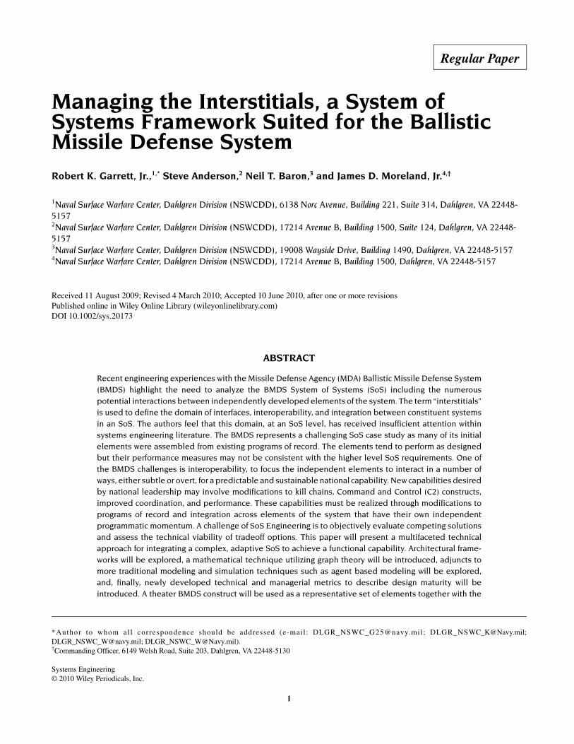
As the U.S. MDA continues to pursue the capability-basedacquisition strategy, and theater BMDS capabilities are de-ployed, the analytical challenge is to understand how toachieve BMDS performance consistent with initial perform-ance goals and predictions. The U.S. DoD has constructed avision for the configuration of the BMDS in 2013 as shownin Figure 1. This is a sea-, land-, and space-based multiservicecapability. Key characteristics of the theater portion of theBMDS are the layered lower and upper tier capability ofPAC-3, Terminal High-Altitude Area Defense (THAAD), andAegis systems with networked sensors, C2, and BM.
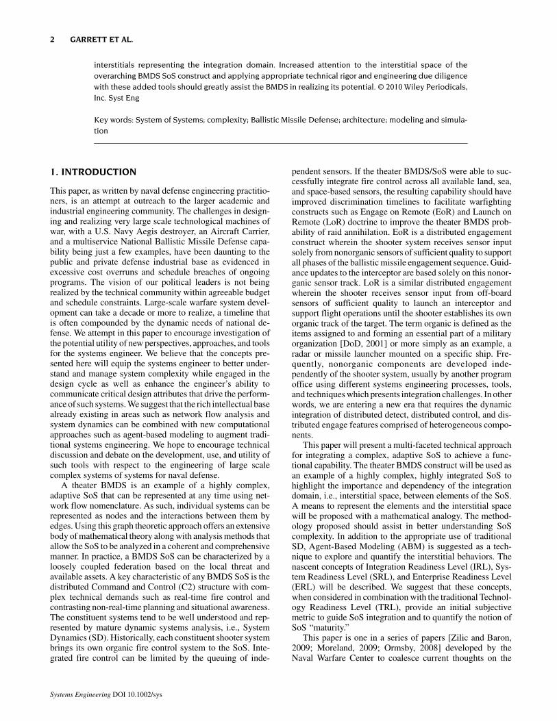
Figure 2 illustrates the Japanese Ballistic Missile DefenseArchitecture. The Japanese BMDS consists of a layered PAC-3 and sea-based Aegis capability with a forward-based TPY-2radar developed in collaboration with the U.S. DoD. TheJapanese Minister of Defense has directed a distributed radar
A SYSTEM OF SYSTEMS FRAMEWORK BALLISTIC MISSILE DEFENSE 3
Systems Engineering DOI 10.1002/sys
Figure 1. U.S. BMDS system configuration for 2013.
Figure 2. Japanese BMD architecture.
4 GARRETT ET AL.
Systems Engineering DOI 10.1002/sys
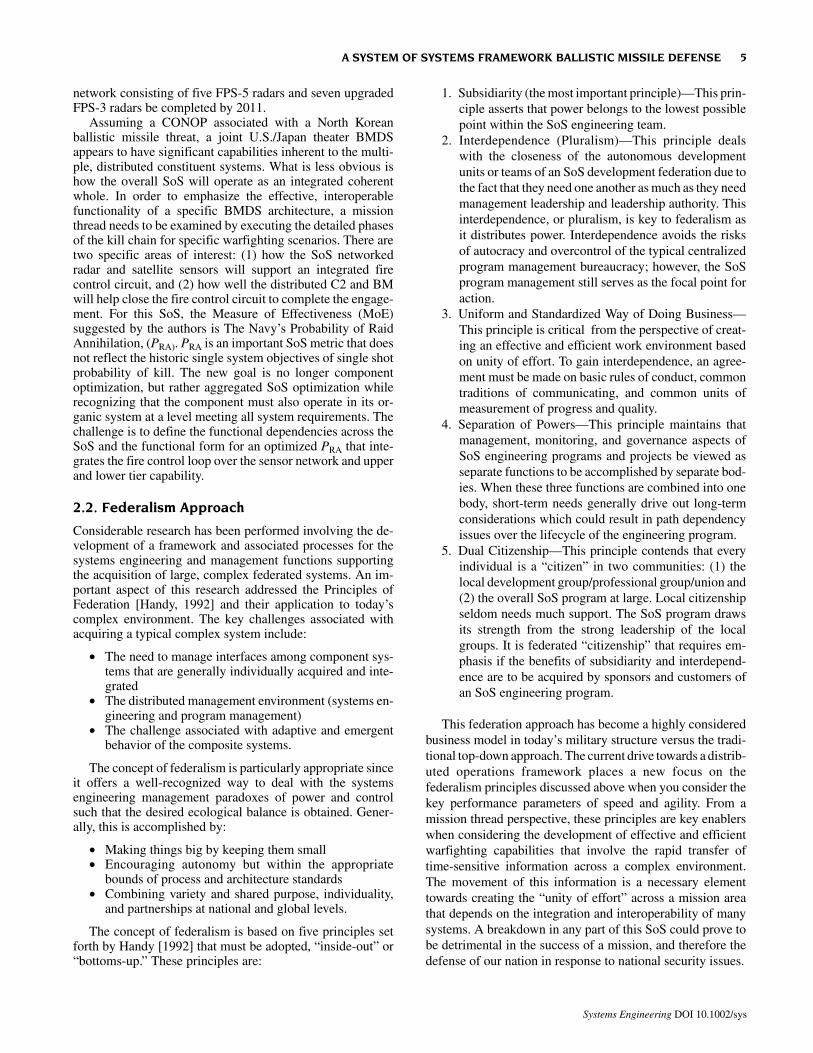
network consisting of five FPS-5 radars and seven upgradedFPS-3 radars be completed by 2011.
Assuming a CONOP associated with a North Koreanballistic missile threat, a joint U.S./Japan theater BMDSappears to have significant capabilities inherent to the multi-ple, distributed constituent systems. What is less obvious ishow the overall SoS will operate as an integrated coherentwhole. In order to emphasize the effective, interoperablefunctionality of a specific BMDS architecture, a missionthread needs to be examined by executing the detailed phasesof the kill chain for specific warfighting scenarios. There aretwo specific areas of interest: (1) how the SoS networkedradar and satellite sensors will support an integrated firecontrol circuit, and (2) how well the distributed C2 and BMwill help close the fire control circuit to complete the engage-ment. For this SoS, the Measure of Effectiveness (MoE)suggested by the authors is The Navy’s Probability of RaidAnnihilation, (PRA). PRA is an important SoS metric that doesnot reflect the historic single system objectives of single shotprobability of kill. The new goal is no longer componentoptimization, but rather aggregated SoS optimization whilerecognizing that the component must also operate in its or-ganic system at a level meeting all system requirements. Thechallenge is to define the functional dependencies across theSoS and the functional form for an optimized PRA that inte-grates the fire control loop over the sensor network and upperand lower tier capability.
2.2. Federalism Approach
Considerable research has been performed involving the de-velopment of a framework and associated processes for thesystems engineering and management functions supportingthe acquisition of large, complex federated systems. An im-portant aspect of this research addressed the Principles ofFederation [Handy, 1992] and their application to today’scomplex environment. The key challenges associated withacquiring a typical complex system include:
• The need to manage interfaces among component sys-tems that are generally individually acquired and inte-grated
• The distributed management environment (systems en-gineering and program management)
• The challenge associated with adaptive and emergentbehavior of the composite systems.
The concept of federalism is particularly appropriate sinceit offers a well-recognized way to deal with the systemsengineering management paradoxes of power and controlsuch that the desired ecological balance is obtained. Gener-ally, this is accomplished by:
• Making things big by keeping them small• Encouraging autonomy but within the appropriate
bounds of process and architecture standards• Combining variety and shared purpose, individuality,
and partnerships at national and global levels.
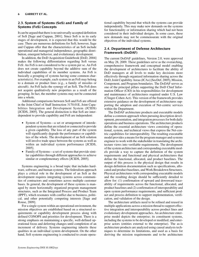
The concept of federalism is based on five principles setforth by Handy [1992] that must be adopted, “inside-out” or“bottoms-up.” These principles are:
1. Subsidiarity (the most important principle)—This prin-ciple asserts that power belongs to the lowest possiblepoint within the SoS engineering team.
2. Interdependence (Pluralism)—This principle dealswith the closeness of the autonomous developmentunits or teams of an SoS development federation due tothe fact that they need one another as much as they needmanagement leadership and leadership authority. Thisinterdependence, or pluralism, is key to federalism asit distributes power. Interdependence avoids the risksof autocracy and overcontrol of the typical centralizedprogram management bureaucracy; however, the SoSprogram management still serves as the focal point foraction.
3. Uniform and Standardized Way of Doing Business—This principle is critical from the perspective of creat-ing an effective and efficient work environment basedon unity of effort. To gain interdependence, an agree-ment must be made on basic rules of conduct, commontraditions of communicating, and common units ofmeasurement of progress and quality.
4. Separation of Powers—This principle maintains thatmanagement, monitoring, and governance aspects ofSoS engineering programs and projects be viewed asseparate functions to be accomplished by separate bod-ies. When these three functions are combined into onebody, short-term needs generally drive out long-termconsiderations which could result in path dependencyissues over the lifecycle of the engineering program.
5. Dual Citizenship—This principle contends that everyindividual is a “citizen” in two communities: (1) thelocal development group/professional group/union and(2) the overall SoS program at large. Local citizenshipseldom needs much support. The SoS program drawsits strength from the strong leadership of the localgroups. It is federated “citizenship” that requires em-phasis if the benefits of subsidiarity and interdepend-ence are to be acquired by sponsors and customers ofan SoS engineering program.
This federation approach has become a highly consideredbusiness model in today’s military structure versus the tradi-tional top-down approach. The current drive towards a distrib-uted operations framework places a new focus on thefederalism principles discussed above when you consider thekey performance parameters of speed and agility. From amission thread perspective, these principles are key enablerswhen considering the development of effective and efficientwarfighting capabilities that involve the rapid transfer oftime-sensitive information across a complex environment.The movement of this information is a necessary elementtowards creating the “unity of effort” across a mission areathat depends on the integration and interoperability of manysystems. A breakdown in any part of this SoS could prove tobe detrimental in the success of a mission, and therefore thedefense of our nation in response to national security issues.
A SYSTEM OF SYSTEMS FRAMEWORK BALLISTIC MISSILE DEFENSE 5
Systems Engineering DOI 10.1002/sys
2.3. System of Systems (SoS) and Family ofSystems (FoS) Concepts
It can be argued that there is no universally accepted definitionof SoS [Sage and Cuppan, 2001]. Since SoS is in its earlystages of development, it is expected that this would be thecase. There are numerous definitions for SoS; however, Sageand Cuppan offer that the characteristics of an SoS includeoperational and managerial independence, geographic distri-bution, emergent behavior, and evolutionary development.
In addition, the DoD Acquisition Guidebook [DoD, 2004]makes the following differentiation regarding SoS versusFoS: An FoS is not considered to be a system per se. An FoSdoes not create capability beyond the additive sum of theindividual capabilities of its member systems. An FoS isbasically a grouping of systems having some common char-acteristic(s). For example, each system in an FoS may belongto a domain or product lines (e.g., a family of missiles oraircraft). An FoS lacks the synergy of an SoS. The FoS doesnot acquire qualitatively new properties as a result of thegrouping. In fact, the member systems may not be connectedinto a whole.
Additional comparisons between SoS and FoS are offeredin the Joint Chief of Staff Instruction 3170.01E, Joint Capa-bilities Integration and Development System (JCIDS)[JCIDS, 2005]. The general distinction is that SoS are inter-dependent to provide capability and FoS are independent:
• System of Systems—a set or arrangement of interde-pendent systems that are related or connected to providea given capability. The loss of any part of the systemwill significantly degrade the performance or capabili-ties of the whole. The development of an SoS solutionwill involve trade space between the systems as well aswithin an individual system performance [JCIDS,2005].
• Family of Systems—a set of systems that provide simi-lar capabilities through different approaches to achievesimilar or complementary effects [JCIDS, 2005].
Systems engineering is a broad topic that includes hard-ware, software, and human systems. The federalism approachplays a critical role in the development of an SoS as thedevelopment requires integrating systems across communi-ties of contractors and sometimes across multiple customerbases. In general, the development of these systems is man-aged by more horizontally organized program managementstructures, such as the Integrated Process and Product Team(IPPT), which resonates with conflict due to business, politi-cal, and other potentially competing interests [Sage andRouse, 2009].
For a single system within an operational environment, themission objectives are established based on a structured re-quirements or capability development process along withdefined CONOPS and priorities for development. There is astrong emphasis on maintaining a specific, well-defined op-erational focus and deferring changes until completion of anincrement of delivery. Systems engineering inherits thesequalities in an individual system development. On the otherhand, SoS systems engineering is conducted to create opera-
tional capability beyond that which the systems can provideindependently. This may make new demands on the systemsfor functionality or information sharing which had not beenconsidered in their individual designs. In some cases, thesenew demands may not be commensurate with the originalobjectives of the individual systems.
2.4. Department of Defense ArchitectureFramework (DoDAF)
The current DoDAF guidelines, Version 2.0, were approvedon May 28, 2009. These guidelines serve as the overarching,comprehensive framework and conceptual model enablingthe development of architectures to facilitate the ability ofDoD managers at all levels to make key decisions moreeffectively through organized information sharing across theDoD, Joint Capability Areas (JCAs) [SecDef, 2005], Mission,Component, and Program boundaries. The DoDAF serves asone of the principal pillars supporting the DoD Chief Infor-mation Officer (CIO) in his responsibilities for developmentand maintenance of architectures required under U.S. Law(Clinger-Cohen Act). This version of the framework providesextensive guidance on the development of architectures sup-porting the adoption and execution of Net-centric serviceswithin the Department.
The DoDAF architecture products and executable modelsdefine a common approach when pursuing description devel-opment, presentation, and integration processes for both dailyoperations and business operations. The architecture productsdefine the essential architecture views consisting of opera-tional, system, and technical views that express the Net-cen-tric capabilities for interoperability. The resulting executablemodel provides a means for the program manager and systemsengineer to work with the stakeholder in translating the archi-tecture views into verifiable requirements. The developmentof the system architecture and corresponding executable mod-els provide a way to capture the definition of the systemrequirements and functional and physical architectures thatdefine the functional, allocated, and product baselines. Theoutput of this process is the physical design that results indesign definition documentation such as specifications, allo-cated and product baselines, and Work Breakdown Structures.Physical architectures with corresponding executable modelsand the resulting design should be sufficiently detailed toallow for: (1) confirmation of upward and downward trace-ability of requirements across the functional, allocated, andproduct baselines and (2) confirmation of interoperability andopen system performance requirements, and sufficient prod-uct and process definition to support implementation, verifi-cation, and validation of the design.
The architecture artifacts need to be refined and reused inmultiple applications across a mission thread to support effec-tive integration and interoperability across product lines andevolutionary development approaches. An architecture enter-prise model depicts the enterprise; its constituent systems,including the systems to be developed or modified; and enter-prise actors (entities external to the enterprise). The as-isarchitecture products are analyzed using causal analysis tech-niques to determine its limitations, and used as a basis forderiving the mission requirements and to-be architecture
6 GARRETT ET AL.
Systems Engineering DOI 10.1002/sys
products. The mission requirements are specified in terms ofthe mission/enterprise objectives, measures of effectiveness,and top-level use cases. The use cases and scenarios capturethe enterprise functionality.
Overall, the flow of the Architecture Based Systems Engi-neering (ABSE) processes is iterative within any one phaseof the acquisition process and is recursive at lower and lowerlevels of the system structure [Sage and Rouse, 2009]. Themodels within this systems engineering process are appliedto allow an orderly progression from one level of developmentto the next more detailed level through the use of functional,allocated, and product baselines under proper configurationmanagement. The processes are used for the development ofsystem, subsystems, and system components as well as for thesupporting or enabling systems used for the testing, produc-tion, operation, training, support, and disposal of that system.System architectures provide a means to establish an unprece-dented level of interoperability in all types of systems devel-opment. Architectures serve as a systems engineering toolwith the ability to keep track of current and future descriptionsof a “domain” composed of components and their intercon-nections, actions or activities those components perform, andrules or constraints for those activities. The baseline capturedin the architectures serves as an important guide to acquisitiondecisions as well as defining operational concepts. The ulti-mate goal is to strive for the integration of systems, bothlegacy and new, with the intent of acquiring interoperablesystems. The focus has changed from component systemdesign (platforms and systems) to SoS integration. Use ofsystem architectures and models are essential when cus-tomer/user needs are ill-structured and the likely system isunprecedented and complex.
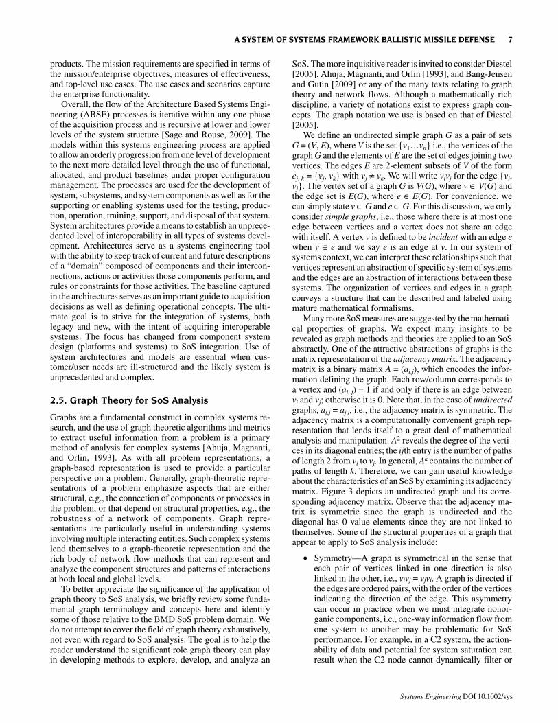
2.5. Graph Theory for SoS Analysis
Graphs are a fundamental construct in complex systems re-search, and the use of graph theoretic algorithms and metricsto extract useful information from a problem is a primarymethod of analysis for complex systems [Ahuja, Magnanti,and Orlin, 1993]. As with all problem representations, agraph-based representation is used to provide a particularperspective on a problem. Generally, graph-theoretic repre-sentations of a problem emphasize aspects that are eitherstructural, e.g., the connection of components or processes inthe problem, or that depend on structural properties, e.g., therobustness of a network of components. Graph repre-sentations are particularly useful in understanding systemsinvolving multiple interacting entities. Such complex systemslend themselves to a graph-theoretic representation and therich body of network flow methods that can represent andanalyze the component structures and patterns of interactionsat both local and global levels.
To better appreciate the significance of the application ofgraph theory to SoS analysis, we briefly review some funda-mental graph terminology and concepts here and identifysome of those relative to the BMD SoS problem domain. Wedo not attempt to cover the field of graph theory exhaustively,not even with regard to SoS analysis. The goal is to help thereader understand the significant role graph theory can playin developing methods to explore, develop, and analyze an
SoS. The more inquisitive reader is invited to consider Diestel[2005], Ahuja, Magnanti, and Orlin [1993], and Bang-Jensenand Gutin [2009] or any of the many texts relating to graphtheory and network flows. Although a mathematically richdiscipline, a variety of notations exist to express graph con-cepts. The graph notation we use is based on that of Diestel[2005].
We define an undirected simple graph G as a pair of setsG = (V, E), where V is the set {v1…vn} i.e., the vertices of thegraph G and the elements of E are the set of edges joining twovertices. The edges E are 2-element subsets of V of the formej, k = {vj, vk} with vj ≠ vk. We will write vivj for the edge {vi,vj}. The vertex set of a graph G is V(G), where v ∈ V(G) andthe edge set is E(G), where e ∈ E(G). For convenience, wecan simply state v ∈ G and e ∈ G. For this discussion, we onlyconsider simple graphs, i.e., those where there is at most oneedge between vertices and a vertex does not share an edgewith itself. A vertex v is defined to be incident with an edge ewhen v ∈ e and we say e is an edge at v. In our system ofsystems context, we can interpret these relationships such thatvertices represent an abstraction of specific system of systemsand the edges are an abstraction of interactions between thesesystems. The organization of vertices and edges in a graphconveys a structure that can be described and labeled usingmature mathematical formalisms.
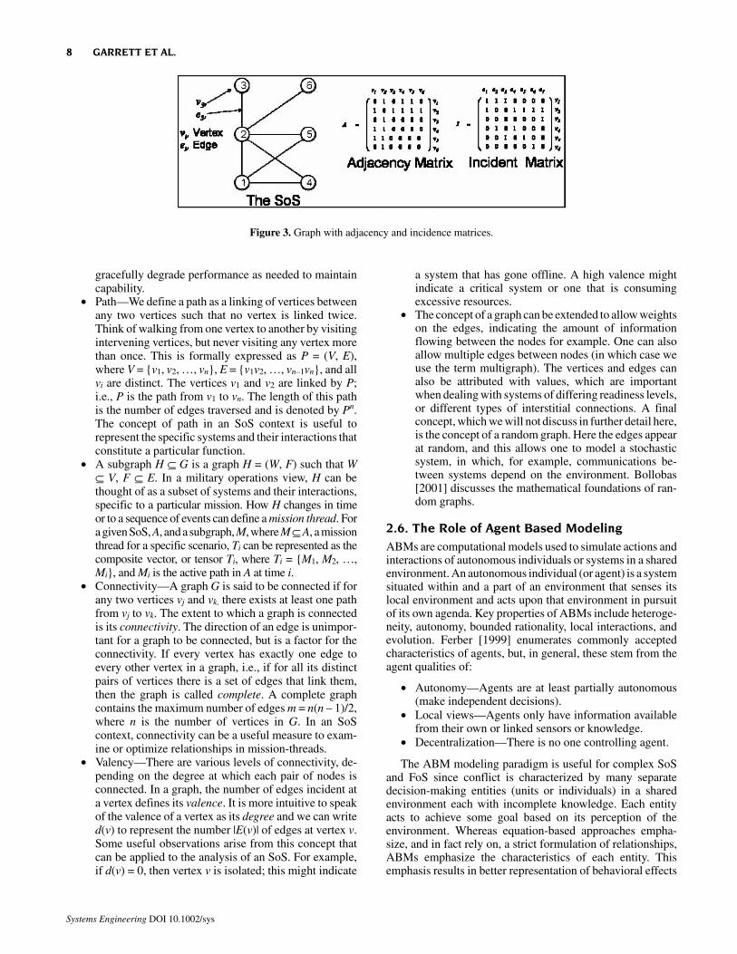
Many more SoS measures are suggested by the mathemati-cal properties of graphs. We expect many insights to berevealed as graph methods and theories are applied to an SoSabstractly. One of the attractive abstractions of graphs is thematrix representation of the adjacency matrix. The adjacencymatrix is a binary matrix A = (ai,j), which encodes the infor-mation defining the graph. Each row/column corresponds toa vertex and (ai, j) = 1 if and only if there is an edge betweenvi and vj; otherwise it is 0. Note that, in the case of undirectedgraphs, ai,j = aj,i, i.e., the adjacency matrix is symmetric. Theadjacency matrix is a computationally convenient graph rep-resentation that lends itself to a great deal of mathematicalanalysis and manipulation. A2 reveals the degree of the verti-ces in its diagonal entries; the ijth entry is the number of pathsof length 2 from vi to vj. In general, Ak contains the number ofpaths of length k. Therefore, we can gain useful knowledgeabout the characteristics of an SoS by examining its adjacencymatrix. Figure 3 depicts an undirected graph and its corre-sponding adjacency matrix. Observe that the adjacency ma-trix is symmetric since the graph is undirected and thediagonal has 0 value elements since they are not linked tothemselves. Some of the structural properties of a graph thatappear to apply to SoS analysis include:
• Symmetry—A graph is symmetrical in the sense thateach pair of vertices linked in one direction is alsolinked in the other, i.e., vivj = vjvi. A graph is directed ifthe edges are ordered pairs, with the order of the verticesindicating the direction of the edge. This asymmetrycan occur in practice when we must integrate nonor-ganic components, i.e., one-way information flow fromone system to another may be problematic for SoSperformance. For example, in a C2 system, the action-ability of data and potential for system saturation canresult when the C2 node cannot dynamically filter or
A SYSTEM OF SYSTEMS FRAMEWORK BALLISTIC MISSILE DEFENSE 7
Systems Engineering DOI 10.1002/sys
gracefully degrade performance as needed to maintaincapability.
• Path—We define a path as a linking of vertices betweenany two vertices such that no vertex is linked twice.Think of walking from one vertex to another by visitingintervening vertices, but never visiting any vertex morethan once. This is formally expressed as P = (V, E),where V = {v1, v2, …, vn}, E = {v1v2, …, vn–1vn}, and allvi are distinct. The vertices v1 and v2 are linked by P;i.e., P is the path from v1 to vn. The length of this pathis the number of edges traversed and is denoted by Pn.The concept of path in an SoS context is useful torepresent the specific systems and their interactions thatconstitute a particular function.
• A subgraph H ⊆ G is a graph H = (W, F) such that W⊆ V, F ⊆ E. In a military operations view, H can bethought of as a subset of systems and their interactions,specific to a particular mission. How H changes in timeor to a sequence of events can define a mission thread. Fora given SoS, A, and a subgraph, M, where M ⊆ A, a missionthread for a specific scenario, Ti can be represented as thecomposite vector, or tensor Ti, where Ti = {M1, M2, …,Mi}, and Mi is the active path in A at time i.
• Connectivity—A graph G is said to be connected if forany two vertices vj and vk, there exists at least one pathfrom vj to vk. The extent to which a graph is connectedis its connectivity. The direction of an edge is unimpor-tant for a graph to be connected, but is a factor for theconnectivity. If every vertex has exactly one edge toevery other vertex in a graph, i.e., if for all its distinctpairs of vertices there is a set of edges that link them,then the graph is called complete. A complete graphcontains the maximum number of edges m = n(n – 1)/2,where n is the number of vertices in G. In an SoScontext, connectivity can be a useful measure to exam-ine or optimize relationships in mission-threads.
• Valency—There are various levels of connectivity, de-pending on the degree at which each pair of nodes isconnected. In a graph, the number of edges incident ata vertex defines its valence. It is more intuitive to speakof the valence of a vertex as its degree and we can writed(v) to represent the number |E(v)| of edges at vertex v.Some useful observations arise from this concept thatcan be applied to the analysis of an SoS. For example,if d(v) = 0, then vertex v is isolated; this might indicate
a system that has gone offline. A high valence mightindicate a critical system or one that is consumingexcessive resources.
• The concept of a graph can be extended to allow weightson the edges, indicating the amount of informationflowing between the nodes for example. One can alsoallow multiple edges between nodes (in which case weuse the term multigraph). The vertices and edges canalso be attributed with values, which are importantwhen dealing with systems of differing readiness levels,or different types of interstitial connections. A finalconcept, which we will not discuss in further detail here,is the concept of a random graph. Here the edges appearat random, and this allows one to model a stochasticsystem, in which, for example, communications be-tween systems depend on the environment. Bollobas[2001] discusses the mathematical foundations of ran-dom graphs.
2.6. The Role of Agent Based Modeling ABMs are computational models used to simulate actions andinteractions of autonomous individuals or systems in a sharedenvironment. An autonomous individual (or agent) is a systemsituated within and a part of an environment that senses itslocal environment and acts upon that environment in pursuitof its own agenda. Key properties of ABMs include heteroge-neity, autonomy, bounded rationality, local interactions, andevolution. Ferber [1999] enumerates commonly acceptedcharacteristics of agents, but, in general, these stem from theagent qualities of:
• Autonomy—Agents are at least partially autonomous(make independent decisions).
• Local views—Agents only have information availablefrom their own or linked sensors or knowledge.
• Decentralization—There is no one controlling agent. The ABM modeling paradigm is useful for complex SoS
and FoS since conflict is characterized by many separatedecision-making entities (units or individuals) in a sharedenvironment each with incomplete knowledge. Each entityacts to achieve some goal based on its perception of theenvironment. Whereas equation-based approaches empha-size, and in fact rely on, a strict formulation of relationships,ABMs emphasize the characteristics of each entity. Thisemphasis results in better representation of behavioral effects
Figure 3. Graph with adjacency and incidence matrices.
8 GARRETT ET AL.
Systems Engineering DOI 10.1002/sys
associated with a complex SoS, especially where there is littleempirical data to support characterizing relationships orwhere the number of potential interactions is intractable. Forexample, ABMs allow individual weapon-target engagementsto be modeled using traditional techniques but embeddedwithin a larger scale simulation of decision-making andmovement. This ABM environment also allows for the pres-ervation of “accidents” that determine the outcome of battles(e.g., the lucky shot that cripples a major unit, the surprisecontact, peculiar geographies, etc.). In short, the ABM pro-vides a means to understand how the actions and interactionsof friendly, neutral, and hostile agents shape the full Detect-to-Engage sequence.
The strength of ABMs is demonstrated by the basic ideathat the best answer or alternatives are obtained through agrowing process coined “generative modeling.” It is mucheasier to ferret out the specific reasons for behaviors whenexamining the individual states of growth within a complexsystem. The best way to perform this analysis is throughmultidimensional visualization techniques such as projectingthe emergent behavior in some appropriate n-dimensionalstate space. Key properties of ABMs include heterogeneity,autonomy, bounded rationality, local interactions, and evolu-tion. The ABM allows the analysts to rapidly investigate therealm of possibilities for state spaces in a systematic nature.This modeling technique supports more direct experimenta-tion by playing “what-if” games where the model can thinkdirectly in terms of familiar operational processes, rather thanhaving to translate them into equations relating observables.In addition, models are easier to translate back into practiceby transcribing the modified behaviors of the agents into taskdescriptions (functional requirements) for the underlyingphysical entities in the real world.
3. A NEW APPROACH TO QUANTIFICATION OFAN SOS: MANAGING THE INTERSTITIALRELATIONSHIPS
3.1. An SoS as a Simple Adjacency Matrix
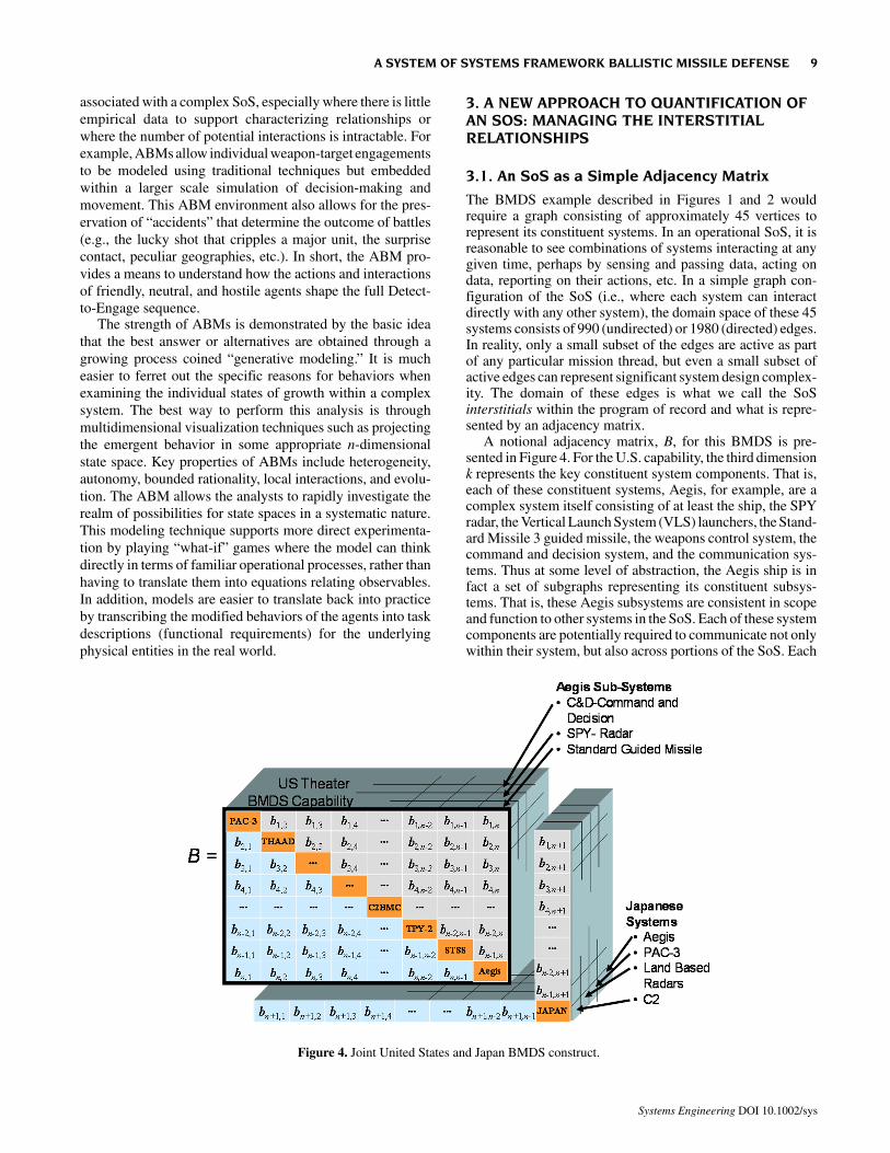
The BMDS example described in Figures 1 and 2 wouldrequire a graph consisting of approximately 45 vertices torepresent its constituent systems. In an operational SoS, it isreasonable to see combinations of systems interacting at anygiven time, perhaps by sensing and passing data, acting ondata, reporting on their actions, etc. In a simple graph con-figuration of the SoS (i.e., where each system can interactdirectly with any other system), the domain space of these 45systems consists of 990 (undirected) or 1980 (directed) edges.In reality, only a small subset of the edges are active as partof any particular mission thread, but even a small subset ofactive edges can represent significant system design complex-ity. The domain of these edges is what we call the SoSinterstitials within the program of record and what is repre-sented by an adjacency matrix.
A notional adjacency matrix, B, for this BMDS is pre-sented in Figure 4. For the U.S. capability, the third dimensionk represents the key constituent system components. That is,each of these constituent systems, Aegis, for example, are acomplex system itself consisting of at least the ship, the SPYradar, the Vertical Launch System (VLS) launchers, the Stand-ard Missile 3 guided missile, the weapons control system, thecommand and decision system, and the communication sys-tems. Thus at some level of abstraction, the Aegis ship is infact a set of subgraphs representing its constituent subsys-tems. That is, these Aegis subsystems are consistent in scopeand function to other systems in the SoS. Each of these systemcomponents are potentially required to communicate not onlywithin their system, but also across portions of the SoS. Each
Figure 4. Joint United States and Japan BMDS construct.
A SYSTEM OF SYSTEMS FRAMEWORK BALLISTIC MISSILE DEFENSE 9
Systems Engineering DOI 10.1002/sys
Aegis ship is then a diagonal term in the i,j plane (as is eachPAC-3 and THAAD battery, TPY-2, C2BMC, etc.), and SoSensemble in i,j,k space. The first observation is that eachcountry’s capabilities are not presented on the same basiswithin the graph; that “Aegis” is shown as a subsystem in theJapanese systems. This inconsistency is noted and deliber-ately represents the potential for a difference in perspective;perhaps in terms of architectures, systems engineering proc-esses, function, etc., that may affect interoperability. Forexample, a Japanese Aegis system must be represented as adiscrete system component. This requires access to the appro-priate Subject Matter Expert (SME) to provide a common
basis and physical and functional decomposition across theSoS down to an appropriate level. Similar functional decom-positions in the k dimension for each system are required. Theoperational interplay, if and when relevant, of the systems andtheir components must be architecturally described in suffi-cient technical detail to flow systems engineering require-ments, execute detailed design evolutions, and, finally, verify,validate, and certify the relationship upon deployment. Forexample, there must be sufficient transparency across the SoSto understand and quantify the functionality, differences, in-terfaces, etc. to model the entire SoS domain. This knowledgemust be sufficient to integrate scenarios ranging from singlesystem/element engagement of a single threat (core capabil-ity), to an integrated fire control which must be exploited toaddress single or multielement engagement of single threat orraids and reengagements as needed. This matrix may repre-sent the integration requirements for a full theater BMDSmission capability or be a subset entry of a larger groupingdefining relationships with additional primary elements. Thefire control loop(s) exploited by each “shooter” quickly be-comes multidimensional strings through the graph. The firecontrol loop becomes a complex adaptive system of systemson its own. This nested complexity is quite common in largescale integrated systems and clearly complicates maintainingthe organic human control over the entire fire control loop.
3.2. Application to the Fire Control Loop
In the case of the BMDS as represented by matrix B, in Figure4, any specific mission M can be defined such that M ⊆ B. Thesystems involved in this mission will be notionally defined for
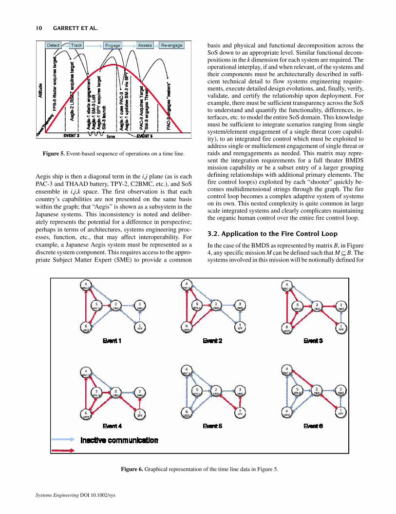
Figure 5. Event-based sequence of operations on a time line.
Figure 6. Graphical representation of the time line data in Figure 5.
10 GARRETT ET AL.
Systems Engineering DOI 10.1002/sys
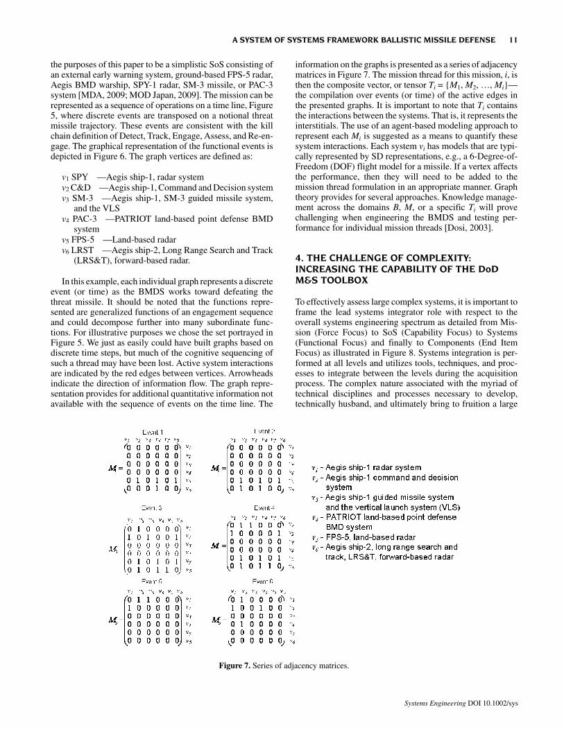
the purposes of this paper to be a simplistic SoS consisting ofan external early warning system, ground-based FPS-5 radar,Aegis BMD warship, SPY-1 radar, SM-3 missile, or PAC-3system [MDA, 2009; MOD Japan, 2009]. The mission can berepresented as a sequence of operations on a time line, Figure5, where discrete events are transposed on a notional threatmissile trajectory. These events are consistent with the killchain definition of Detect, Track, Engage, Assess, and Re-en-gage. The graphical representation of the functional events isdepicted in Figure 6. The graph vertices are defined as:
v1 SPY —Aegis ship-1, radar systemv2 C&D —Aegis ship-1, Command and Decision systemv3 SM-3 —Aegis ship-1, SM-3 guided missile system,
and the VLSv4 PAC-3 —PATRIOT land-based point defense BMD
systemv5 FPS-5 —Land-based radarv6 LRST —Aegis ship-2, Long Range Search and Track
(LRS&T), forward-based radar.
In this example, each individual graph represents a discreteevent (or time) as the BMDS works toward defeating thethreat missile. It should be noted that the functions repre-sented are generalized functions of an engagement sequenceand could decompose further into many subordinate func-tions. For illustrative purposes we chose the set portrayed inFigure 5. We just as easily could have built graphs based ondiscrete time steps, but much of the cognitive sequencing ofsuch a thread may have been lost. Active system interactionsare indicated by the red edges between vertices. Arrowheadsindicate the direction of information flow. The graph repre-sentation provides for additional quantitative information notavailable with the sequence of events on the time line. The
information on the graphs is presented as a series of adjacencymatrices in Figure 7. The mission thread for this mission, i, isthen the composite vector, or tensor Ti = {M1, M2, …, Mi}—the compilation over events (or time) of the active edges inthe presented graphs. It is important to note that Ti containsthe interactions between the systems. That is, it represents theinterstitials. The use of an agent-based modeling approach torepresent each Mi is suggested as a means to quantify thesesystem interactions. Each system vi has models that are typi-cally represented by SD representations, e.g., a 6-Degree-of-Freedom (DOF) flight model for a missile. If a vertex affectsthe performance, then they will need to be added to themission thread formulation in an appropriate manner. Graphtheory provides for several approaches. Knowledge manage-ment across the domains B, M, or a specific Ti will provechallenging when engineering the BMDS and testing per-formance for individual mission threads [Dosi, 2003].
4. THE CHALLENGE OF COMPLEXITY:INCREASING THE CAPABILITY OF THE DoDM&S TOOLBOX
To effectively assess large complex systems, it is important toframe the lead systems integrator role with respect to theoverall systems engineering spectrum as detailed from Mis-sion (Force Focus) to SoS (Capability Focus) to Systems(Functional Focus) and finally to Components (End ItemFocus) as illustrated in Figure 8. Systems integration is per-formed at all levels and utilizes tools, techniques, and proc-esses to integrate between the levels during the acquisitionprocess. The complex nature associated with the myriad oftechnical disciplines and processes necessary to develop,technically husband, and ultimately bring to fruition a large
Figure 7. Series of adjacency matrices.
A SYSTEM OF SYSTEMS FRAMEWORK BALLISTIC MISSILE DEFENSE 11
Systems Engineering DOI 10.1002/sys
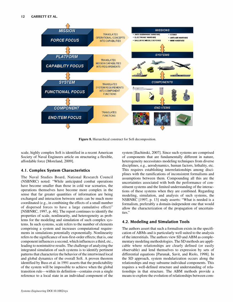
scale, highly complex SoS is identified in a recent AmericanSociety of Naval Engineers article on structuring a flexible,affordable force [Moreland, 2009].
4.1. Complex System Characteristics
The Naval Studies Board, National Research Council(NSBNRC) noted: “While anticipated combat operationshave become smaller than those in cold war scenarios, theoperations themselves have become more complex in thesense that far greater quantities of information are beingexchanged and interaction between units can be much morecoordinated (e.g., in combining the effects of a small numberof dispersed forces to have a large cumulative effect)”[NSBNRC, 1997, p. 46]. The report continues to identify theproperties of scale, nonlinearity, and heterogeneity as prob-lems for the modeling and simulation of such complex sys-tems. In such systems, scale refers to the number of elementscomprising a system and increases computational require-ments in simulations potentially exponentially. Nonlinearityrefers to the significance of non-first-order effects; that is, onecomponent influences a second, which influences a third, etc.,leading to nonintuitive results. The challenge of analyzing theintegrated simulation of such systems is to identify pertinentpatterns that characterize the behavior of the intertwined localand global dynamics of the overall SoS. A proven theoremidentified by Buss et al. in 1991 asserts that the predictabilityof the system will be impossible to achieve when the globaltransition rule—within its definition—contains even a singlereference to a local state in an individual component of the
system [Ilachinski, 2007]. Since such systems are comprisedof components that are fundamentally different in nature,heterogeneity necessitates modeling techniques from diversedisciplines, e.g., aerodynamics, human factors, lethality, etc.This requires establishing interrelationships among disci-plines with the ramifications of inconsistent formalisms andassumptions between them. Compounding all this are theuncertainties associated with both the performance of con-stituent systems and the limited understanding of the interac-tions of these systems when they are combined. Regardingmodeling, simulation, and analysis of such systems, theNSBNRC [1997, p. 13] study asserts: “What is needed is aformalism, preferably a domain-independent one that wouldallow the characterization of the propagation of uncertain-ties.”
4.2. Modeling and Simulation Tools
The authors assert that such a formalism exists in the specifi-cation of ABMs and is particularly well suited to the analysisof the interstitials. The authors view SD and ABM as comple-mentary modeling methodologies. The SD methods are appli-cable where relationships are clearly defined (or easilyobservable) and lend themselves to expression by sets ofdifferential equations [Parunak, Savit, and Riolo, 1998]. Inthe SD approach, system modularization occurs along therelationships and may subsume individual components. Thisrequires a well-defined structure and understanding of rela-tionships in that structure. The ABM methods provide ameans to explore the evolution of relationships between com-
Figure 8. Hierarchical construct for SoS decomposition.
12 GARRETT ET AL.
Systems Engineering DOI 10.1002/sys
ponents since ABMs emphasize the specification of inde-pendent components. In the ABM, it is through the interac-tions that occur between components at a microscale that themacroscale system characteristics can emerge [Schieritz andMilling, 2003]. As such, ABMs provide a means to examinesystem performance where the interrelationships betweencomponents are not well understood a priori. In this manner,ABM methods provide a complement to the traditional ele-ment centric equation-based/physics-based modeling ap-proaches typical of system dynamics. The Naval StudiesBoard [NSBNRC, 1997, p. 47] has addressed these areas andobserved: “Some of the most interesting new forms of mod-eling involve so-called ‘systems’ in which low-level entitieswith relatively simple attributes and behaviors can collec-tively produce (or ‘generate’) complex and realistic ‘emer-gent’ system behaviors. This is potentially a powerfulapproach to understanding complex adaptive systems gener-ally—in fields as diverse as ecology, economics, and militarycommand and control.” The multiple tiers of Figure 8 can beviewed as a mapping of agent’s behaviors during interactionsin small groups emerging to the bigger picture at the uppertiers of investigating force-on-force interactions [Siel, 2010].Many emergent behaviors occur because of the interaction inthe lower-level rules due to the abundance of nonlinear rela-tionships occurring in a web framework. In practicality, it iscritical to keep the agent level rules simple enough to achievethe desired dynamical behavior at the higher tiers.
4.3. Representation of Complex Systems
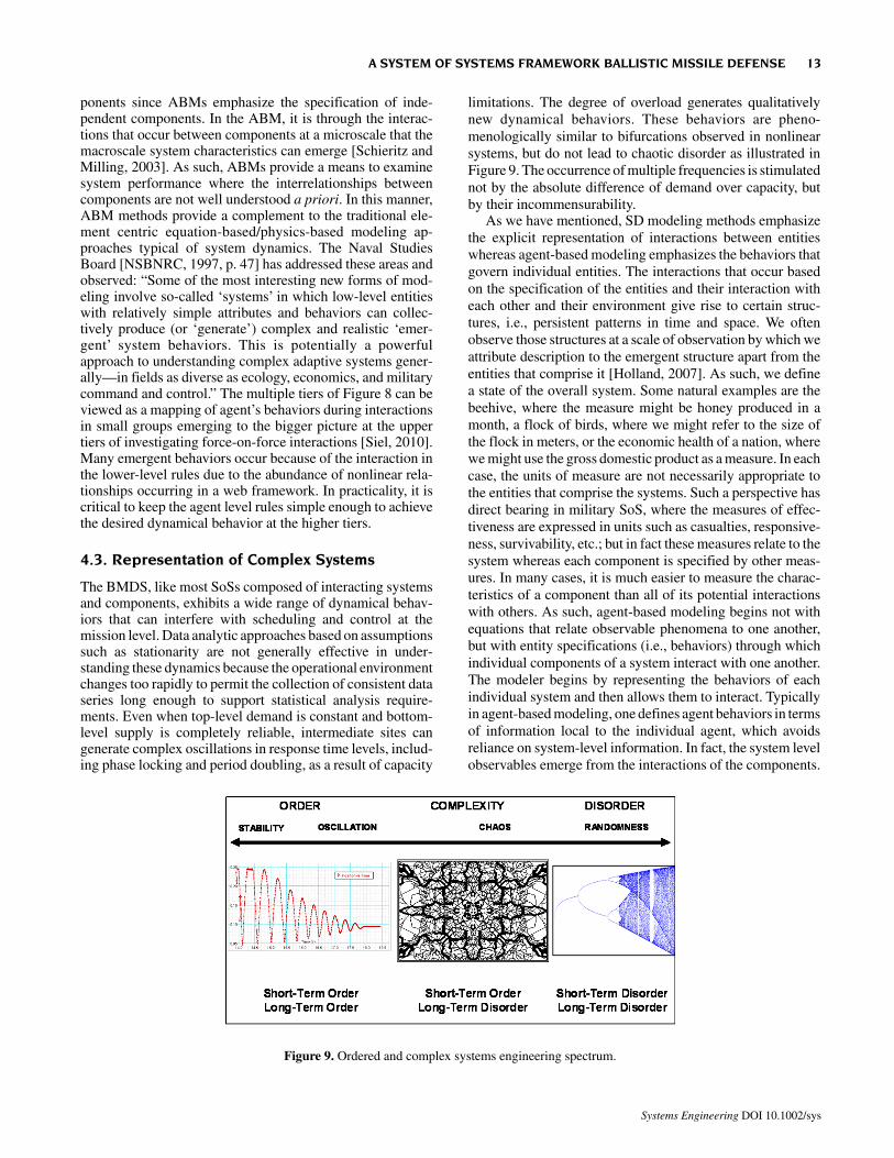
The BMDS, like most SoSs composed of interacting systemsand components, exhibits a wide range of dynamical behav-iors that can interfere with scheduling and control at themission level. Data analytic approaches based on assumptionssuch as stationarity are not generally effective in under-standing these dynamics because the operational environmentchanges too rapidly to permit the collection of consistent dataseries long enough to support statistical analysis require-ments. Even when top-level demand is constant and bottom-level supply is completely reliable, intermediate sites cangenerate complex oscillations in response time levels, includ-ing phase locking and period doubling, as a result of capacity
limitations. The degree of overload generates qualitativelynew dynamical behaviors. These behaviors are pheno-menologically similar to bifurcations observed in nonlinearsystems, but do not lead to chaotic disorder as illustrated inFigure 9. The occurrence of multiple frequencies is stimulatednot by the absolute difference of demand over capacity, butby their incommensurability.
As we have mentioned, SD modeling methods emphasizethe explicit representation of interactions between entitieswhereas agent-based modeling emphasizes the behaviors thatgovern individual entities. The interactions that occur basedon the specification of the entities and their interaction witheach other and their environment give rise to certain struc-tures, i.e., persistent patterns in time and space. We oftenobserve those structures at a scale of observation by which weattribute description to the emergent structure apart from theentities that comprise it [Holland, 2007]. As such, we definea state of the overall system. Some natural examples are thebeehive, where the measure might be honey produced in amonth, a flock of birds, where we might refer to the size ofthe flock in meters, or the economic health of a nation, wherewe might use the gross domestic product as a measure. In eachcase, the units of measure are not necessarily appropriate tothe entities that comprise the systems. Such a perspective hasdirect bearing in military SoS, where the measures of effec-tiveness are expressed in units such as casualties, responsive-ness, survivability, etc.; but in fact these measures relate to thesystem whereas each component is specified by other meas-ures. In many cases, it is much easier to measure the charac-teristics of a component than all of its potential interactionswith others. As such, agent-based modeling begins not withequations that relate observable phenomena to one another,but with entity specifications (i.e., behaviors) through whichindividual components of a system interact with one another.The modeler begins by representing the behaviors of eachindividual system and then allows them to interact. Typicallyin agent-based modeling, one defines agent behaviors in termsof information local to the individual agent, which avoidsreliance on system-level information. In fact, the system levelobservables emerge from the interactions of the components.
Figure 9. Ordered and complex systems engineering spectrum.
A SYSTEM OF SYSTEMS FRAMEWORK BALLISTIC MISSILE DEFENSE 13
Systems Engineering DOI 10.1002/sys
5. MAINTAINING ALIGNMENT OF THE SOS,BOTH ELEMENTS AND INTERSTITIAL
5.1. Interface Readiness
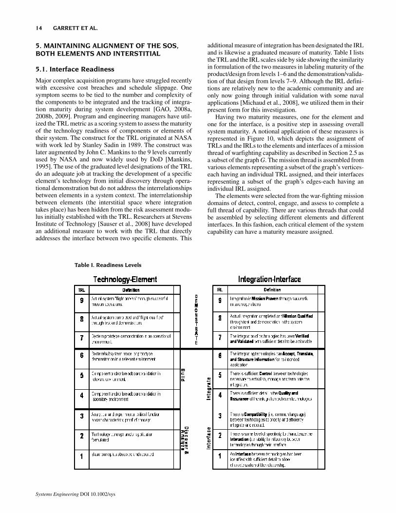
Major complex acquisition programs have struggled recentlywith excessive cost breaches and schedule slippage. Onesymptom seems to be tied to the number and complexity ofthe components to be integrated and the tracking of integra-tion maturity during system development [GAO, 2008a,2008b, 2009]. Program and engineering managers have util-ized the TRL metric as a scoring system to assess the maturityof the technology readiness of components or elements oftheir system. The construct for the TRL originated at NASAwith work led by Stanley Sadin in 1989. The construct waslater augmented by John C. Mankins to the 9 levels currentlyused by NASA and now widely used by DoD [Mankins,1995]. The use of the graduated level designations of the TRLdo an adequate job at tracking the development of a specificelement’s technology from initial discovery through opera-tional demonstration but do not address the interrelationshipsbetween elements in a system context. The interrelationshipbetween elements (the interstitial space where integrationtakes place) has been hidden from the risk assessment modu-lus initially established with the TRL. Researchers at StevensInstitute of Technology [Sauser et al., 2008] have developedan additional measure to work with the TRL that directlyaddresses the interface between two specific elements. This
additional measure of integration has been designated the IRLand is likewise a graduated measure of maturity. Table I liststhe TRL and the IRL scales side by side showing the similarityin formulation of the two measures in labeling maturity of theproduct/design from levels 1–6 and the demonstration/valida-tion of that design from levels 7–9. Although the IRL defini-tions are relatively new to the academic community and areonly now going through initial validation with some navalapplications [Michaud et al., 2008], we utilized them in theirpresent form for this investigation.
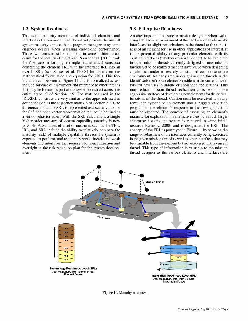
Having two maturity measures, one for the element andone for the interface, is a positive step in assessing overallsystem maturity. A notional application of these measures isrepresented in Figure 10, which depicts the assignment ofTRLs and the IRLs to the elements and interfaces of a missionthread of warfighting capability as described in Section 2.5 asa subset of the graph G. The mission thread is assembled fromvarious elements representing a subset of the graph’s vertices-each having an individual TRL assigned, and their interfacesrepresenting a subset of the graph’s edges-each having anindividual IRL assigned.
The elements were selected from the war-fighting missiondomains of detect, control, engage, and assess to complete afull thread of capability. There are various threads that couldbe assembled by selecting different elements and differentinterfaces. In this fashion, each critical element of the systemcapability can have a maturity measure assigned.
Table I. Readiness Levels
14 GARRETT ET AL.
Systems Engineering DOI 10.1002/sys
5.2. System Readiness
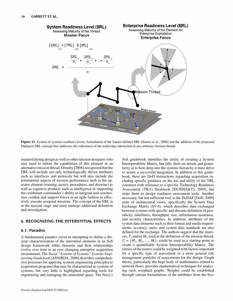
The use of maturity measures of individual elements andinterfaces of a mission thread do not yet provide the overallsystem maturity context that a program manager or systemsengineer desires when assessing end-to-end performance.These two terms must be combined in some fashion to ac-count for the totality of the thread. Sauser et al. [2008] tookthe first step in forming a simple mathematical constructcombining the element TRL with the interface IRL into anoverall SRL (see Sauser et al. [2008] for details on themathematical formulation and equation for SRL). This for-mulation can be seen in Figure 11 and is normalized acrossthe SoS for ease of assessment and reference to other threadsthat may be formed as part of the system construct across theentire graph G of Section 2.5. The matrices used in theIRL/SRL construct are very similar to the approach used todefine the SoS as the adjacency matrix A of Section 3.2. Onedifference is that the SRL is represented as a scalar value forthe SoS and not a vector representation that could be used asa set of behavior rules. With the SRL calculation, a singlehigher-order measure of system capability maturity is nowpossible. Advantages of a set of measures such as the TRL,IRL, and SRL include the ability to relatively compare thematurity (risk) of multiple capability threads the system isexpected to perform, and to identify weak threads and weakelements and interfaces that require additional attention andoversight in the risk reduction plan for the system develop-ment.
5.3. Enterprise Readiness
Another important measure to mission designers when evalu-ating a thread is an assessment of the hardness of an element’sinterfaces for slight perturbations in the thread or the robust-ness of an element for use in other applications of interest. Itis the potential ability of any particular element, with itsexisting interfaces (whether exercised or not), to be exploitedin other mission threads currently designed or new missionthreads yet to be realized that can have value when designingcapabilities under a severely constrained cost or scheduleenvironment. An early step in designing such threads is theidentification of robust elements resident in the current inven-tory for new uses in unique or unplanned applications. Thismay reduce mission thread realization costs over a moreaggressive strategy of developing new elements for the criticalfunctions of the thread. Caution must be exercised with anynovel deployment of an element and a rugged validationprogram of the element’s response in the new applicationmust be executed. The concept of assessing an element’smaturity for exploitation in alternative uses by a much largerenterprise housing the system is captured in some initialresearch [Ormsby, 2008] and is designated the ERL. Theconcept of the ERL is portrayed in Figure 11 by showing therange or robustness of the interfaces currently being exercisedin the given mission thread as well as other interfaces that maybe available from the element but not exercised in the currentthread. This type of information is valuable to the missionthread designer as the various elements and interfaces are
Figure 10. Maturity measures.
A SYSTEM OF SYSTEMS FRAMEWORK BALLISTIC MISSILE DEFENSE 15
Systems Engineering DOI 10.1002/sys
matured during design as well as other mission designers whomay need to utilize the capabilities of this element in analternative mission thread. Ormsby [2008] recognized that theERL will include not only technologically driven attributessuch as interfaces and protocols but will also include thenonmaterial aspects of mission performance such as the op-erator element (training, tactics, procedures, and doctrine) aswell as cognitive products such as intelligence in supportingthe combatant commander’s ability to integrate and synchro-nize combat and support forces in an agile fashion to effec-tively execute assigned missions. The concept of the ERL isat the nascent stage and must undergo additional definitionand investigation.
6. RECOGNIZING THE INTERSTITIAL EFFECTS
6.1. Paradox
A fundamental paradox exists in attempting to define a dis-crete characterization of the interstitial elements in an SoSdesign framework while elements and their relationshipsevolve over time in an ever changing enterprise acquisitionenvironment. The Naval “Systems of Systems” Systems Engi-neering Guidebook [ASN/RDA, 2006] describes comprehen-sive processes for applying systems engineering principles toacquisition programs that may be characterized as systems ofsystems, but very little is highlighted regarding tools forengineering and managing the interstitial space. The Navy’s
SoS guidebook identifies the utility of creating a SystemInteroperability Matrix, but falls short on details and granu-larity as to how deep into the systems hierarchy it must delveto assure a successful integration. In addition to this guide-book, there are DoD instructions regarding acquisition in-cluding specific guidance on the use and utility of the TRLconstruct with reference to a specific Technology ReadinessAssessment (TRA) Deskbook [DUSD[S&T], 2005], butstops there in design readiness assessment tools. Anothernecessary, but not sufficient tool, is the DoDAF [DoD, 2009]suite of architectural views, specifically the System DataExchange Matrix (SV-6), which describes data exchangedbetween systems with specific and discrete definition of peri-odicity, timeliness, throughput, size, information assurance,and security characteristics. In addition, attributes of thesystem data elements such as their format and media require-ments, accuracy, units, and system data standards are alsodefined for the exchange. The authors suggest that the matri-ces, Ti and/or Mi, used in the definition of the mission thread,Ti = {M1, M2, …, Mi}, could be used as a starting point tocreate a quantifiable System Interoperability Matrix. Theentries of the matrix could be weighted with factors importantfor a specific type of assessment or a more general riskmanagement portfolio of assessments for the design. Graphtheory, particularly the large body of mathematics related tonetwork flows, provides mathematical techniques for analyz-ing such weighted graphs. Weights could be establishedthrough various formulations of the attributes from the Sys-
Figure 11. System of systems readiness levels; formulation of the Sauser-defined SRL [Sauser et al., 2006] and the addition of the proposedDahlgren ERL concept that addresses the robustness of the node/edge interaction in any arbitrary mission thread.
16 GARRETT ET AL.
Systems Engineering DOI 10.1002/sys
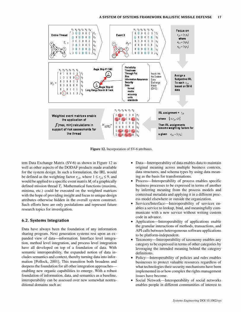
tem Data Exchange Matrix (SV-6) as shown in Figure 12 aswell as other aspects of the DODAF products made availablefor the system design. In such a formulation, the IRL wouldbe defined as the weighting factor rj,k, where 1 ≤ rj,k ≤ 9, andwould be applied to a specific event matrix Mi of a graphicallydefined mission thread Ti. Mathematical functions (maxima,minima, etc.) could be executed on the weighted matriceswith the hope of providing insight and focus to unique designattributes otherwise hidden in the overall system construct.Such efforts here are only postulations and represent futureresearch topics for investigation.
6.2. Systems Integration
Data have always been the foundation of any informationsharing program. Next generation systems rest upon an ex-panded view of data—information. Interface level integra-tion, method level integration, and process level integrationhave all developed on top of a foundation of data. Withsemantic interoperability, the expanded notion of data in-cludes semantics and context, thereby turning data into infor-mation [Pollock, 2001]. This transition both broadens anddeepens the foundation for all other integration approaches—enabling new organic capabilities to emerge. With a robustfoundation of information, data, and semantics as a baseline,interoperability can be assessed over new somewhat nontra-ditional domains such as:
• Data—Interoperability of data enables data to maintainoriginal meaning across multiple business contexts,data structures, and schema types by using data mean-ing as the basis for transformations.
• Process—Interoperability of process enables specificbusiness processes to be expressed in terms of anotherby inferring meaning from the process models andcontextual metadata and applying it in a different proc-ess model elsewhere or outside the organization.
• Services/Interface—Interoperability of services en-ables a service to lookup, bind, and meaningfully com-municate with a new service without writing customcode in advance.
• Application—Interoperability of applications enablethe granular interactions of methods, transactions, andAPI calls between heterogeneous software applicationsto be platform-independent.
• Taxonomy—Interoperability of taxonomy enables anycategory to be expressed in terms of other categories byleveraging the intended meaning behind the categorydefinitions.
• Policy—Interoperability of policies and rules enablesbusinesses to protect valuable resources regardless ofwhat technologies their security mechanisms have beenimplemented in or how complex the rights managementissues have become.
• Social Network—Interoperability of social networksenables people in different communities of interest to
Figure 12. Incorporation of SV-6 attributes.
A SYSTEM OF SYSTEMS FRAMEWORK BALLISTIC MISSILE DEFENSE 17
Systems Engineering DOI 10.1002/sys
network, infer, and discover meaningful connectionsthrough previously unknown contacts and interests.
• The construct used in the mission graphs, as representedby Mi in Figure 6, assumes these interoperability do-mains are included in edges. It is important to note thatthese interoperability domains are stochastic in natureand the mathematical quantification of the interoper-ability domain will lead to the development of prob-ability distribution functions. Thus the stochastic natureof the problem leads naturally to random graph models.When these components can interoperate with either anautomated or a human agent, network configuration canbecome emergent. Emergent behavior implies a level ofdynamism and organic growth that can enable a perva-sive autonomic environment with features that include:
• Self-configuring interface and schema alignmentacross data vocabularies, directory taxonomy, servicedescriptions, and other components
• Self-optimizing transactions, routing, queries, andtransformations
• Self-healing error flows that can recover from other-wise dead-end use cases
• Self-cleansing data validation that can scrub instancevalues from various sources.
The Defense Acquisition University (DAU) Systems En-gineering Fundamentals Guidebook (SEFG) views the opensystems approach as a critical element to the success ofsystems integration by emphasizing flexible interfaces andmaximum interoperability. It states that the key to the opensystems engineering process is interface management. Inter-face management should be done in a more formal andcomprehensive manner to rigidly identify all interfaces andcontrol the flow-down and integration of interface require-ments. The interface becomes controlled elements of thebaseline equal to, or considered part of, the configuration.Management integration approaches can vary based on per-spectives of inactivity, reactivity, or interactivity; however, theincreased complexity of large scale systems integration chal-lenges must favor the latter perspectives over the former toproactively address interoperability issues.
6.3. Readiness Level Assessment Tools
Assessment tools such as “Readiness Levels” can be usefulfor the enterprise architect to understand synchronizationbetween the current architectural definitions of the design andfuture postulations of those architectures along a predictableand programmed evolutionary path. If assessment tools suchas readiness levels are to be useful to the design engineer andthe program manager they must be:
• Clearly defined• Easily understood and applied• Relevant to the design characteristic under assessment• Useful as a measure of maturation progress along an
evolutionary scale• Integrated into design processes and technical reviews
for decision making.
DoD has had some success utilizing the TRL as a subjec-tive measure of an element’s technological maturation.Merely assessing the element in an SoS, however, is toonarrow a view of the relative risk modulus for SoS perform-ance. Major attributes of the SoS performance are realized byhow the elements interact and how they are interconnected;which support the need for additional readiness measures aspart of the design maturity assessment.
6.4. Readiness and Acquisition
DoD design teams are typically strained by demanding sched-ules, constrained budgets, and poorly characterized require-ments that demand discovery activity during the designprocess. The design team must rely on tools and processes toassist in maintaining and continually clarifying design defini-tion. Although an SoS may be engineered and managed abovethe formal acquisition structures of the military services, thesystem elements that comprise the SoS and their interstitialrelationships are realized through military service acquisitionprofessionals. For this reason it is important to understand therelationships between the readiness level designations and thecurrent DoD Acquisition Process [Sauser et al., 2008]. Figure13 illustrates the alignment between the Defense AcquisitionManagement System and the TRL and SRL designators (notethat, in this figure, IRL is not displayed for clarity but is acomponent of the SRL formulation). The TRL maturity des-ignation of the system elements under consideration for theSoS are widespread as they are sourced from many programoffices as well as military services. This disparity comes aboutfrom the simple fact that the preponderance of system ele-ments proposed for the SoS are derived from other majorsystem development acquisitions executing at lower levels ofthe systems engineering hierarchy. When element TRLs arecoupled with interface IRLs, the potential variance of the SRLwidens due to taking into account the additional risk items inits modulus. Sauser et al. (2008) mapped the normalized valueof the SRL to the DoD Acquisition Management System insome recent work with the Naval Postgraduate School inMonterey, CA. This initial mapping is currently undergoingvalidation but is shown in Figure 13 to highlight how late inthe process the SRL matures and achieves certainty (SRL at1.0).
6.5. Summary Metrics Caution
The concept of rolling up metrics into higher-level summa-tions in support of a global assessment of systems maturity isnot new but must always be done with care and includereference to the pedigree of subservient measures. A well-de-signed system may have multiple design threads that satisfyan operational requirement depending on element availability,material condition, and operational demands on the system.The development of a “composite” view of the system, basedon the varying individual contributions of SRLs from subsys-tem element and interface maturities, may provide valuableinsight for senior decision-makers evaluating overall programrisk or design maturity. In any system maturity formulationdescribed above where the fundamental components of asystem readiness calculation (TRL and IRL) are both subjec-
18 GARRETT ET AL.
Systems Engineering DOI 10.1002/sys
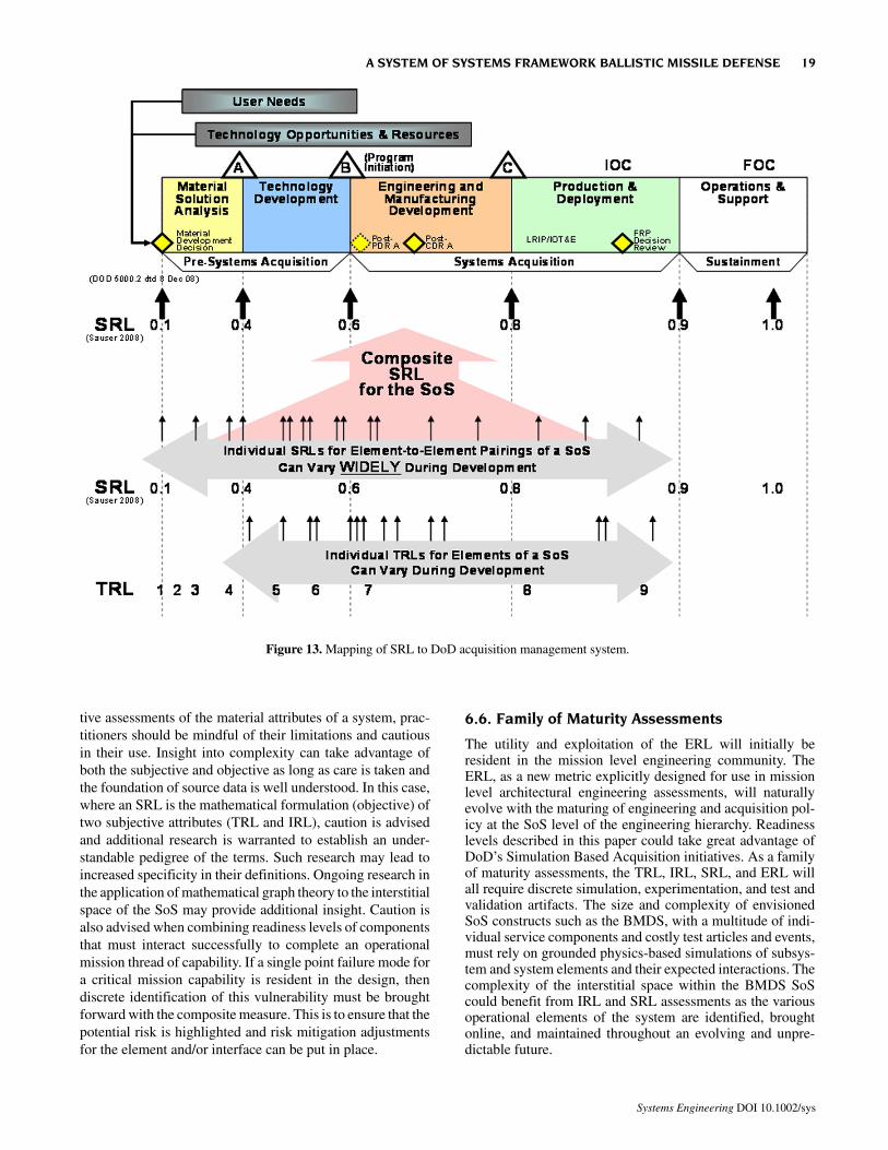
tive assessments of the material attributes of a system, prac-titioners should be mindful of their limitations and cautiousin their use. Insight into complexity can take advantage ofboth the subjective and objective as long as care is taken andthe foundation of source data is well understood. In this case,where an SRL is the mathematical formulation (objective) oftwo subjective attributes (TRL and IRL), caution is advisedand additional research is warranted to establish an under-standable pedigree of the terms. Such research may lead toincreased specificity in their definitions. Ongoing research inthe application of mathematical graph theory to the interstitialspace of the SoS may provide additional insight. Caution isalso advised when combining readiness levels of componentsthat must interact successfully to complete an operationalmission thread of capability. If a single point failure mode fora critical mission capability is resident in the design, thendiscrete identification of this vulnerability must be broughtforward with the composite measure. This is to ensure that thepotential risk is highlighted and risk mitigation adjustmentsfor the element and/or interface can be put in place.
6.6. Family of Maturity Assessments
The utility and exploitation of the ERL will initially beresident in the mission level engineering community. TheERL, as a new metric explicitly designed for use in missionlevel architectural engineering assessments, will naturallyevolve with the maturing of engineering and acquisition pol-icy at the SoS level of the engineering hierarchy. Readinesslevels described in this paper could take great advantage ofDoD’s Simulation Based Acquisition initiatives. As a familyof maturity assessments, the TRL, IRL, SRL, and ERL willall require discrete simulation, experimentation, and test andvalidation artifacts. The size and complexity of envisionedSoS constructs such as the BMDS, with a multitude of indi-vidual service components and costly test articles and events,must rely on grounded physics-based simulations of subsys-tem and system elements and their expected interactions. Thecomplexity of the interstitial space within the BMDS SoScould benefit from IRL and SRL assessments as the variousoperational elements of the system are identified, broughtonline, and maintained throughout an evolving and unpre-dictable future.
Figure 13. Mapping of SRL to DoD acquisition management system.
A SYSTEM OF SYSTEMS FRAMEWORK BALLISTIC MISSILE DEFENSE 19
Systems Engineering DOI 10.1002/sys
7. CONCLUSIONS
7.1. Technically Managing the BMDS
A theater BMDS is an example of a highly complex andadaptive SoS characterized by a loosely coupled federation ofconstituent systems. It is naturally tactical as the local threatand available assets vary with time. Such an SoS exemplifiesan inherently dynamic n2 problem domain that must be ad-dressed in a coherent and comprehensive manner. Althoughthe constituent systems tend to be well understood and arereadily represented by mature equation/physics-based mod-els, the greater challenge of any large n2 problem domain isin identifying and understanding the interstitials, i.e., thenumerous interactions between the independently developedelements of the SoS typically considered under the constructof interoperability. These interstitials can be viewed as inte-gration paths or integration sites. Analytically, the constituentsystems and their interactions can be represented using graphtheory by nodes and edges, respectively. It is worthy to notethat both the nodes and their interactions can, and do, evolveover time and, as such, give rise to spiral and evolutionarydevelopment processes. In the case of theater BMDS, thechallenge of understanding the interstitials is compounded bythe distributed C2 structure where connectivity between theconstituent systems tends to be based on LINK16 satellitecommunications and the fact that each constituent shootersystem brings its own organic fire control system to the SoS.As such, the system represents only a very modest level ofintegration. Whereas the current integrated fire control ap-proach tends toward being limited to queuing, if the theaterBMDS/SoS were able to truly integrate fire control across allavailable land-, sea-, and space-based sensors, a capabilityresulting in improved discrimination timelines that facilitateEoR and LoR doctrine would improve the theater BMDS PRA.When looking at a notional, joint, integrated United States andJapanese theater BMDS to defend against a ballistic missileraid from North Korea, the number of constituent systems(vertices) approaches several dozen and the number of inter-stitials (edges) is on the order of 1000. Traditional highfidelity system dynamics simulations (equation-based) areavailable for quantifying the performance of constituent sys-tems, but not the integrated BMDS (SoS). There are currentlyno tools to focus on the integration of the nodes into a coherenttheater BMDS, especially when the threat is composed ofraids and highly cluttered target scenes. The authors recom-mend the addition of agent-based models to facilitate integra-tion across the possible 1000 interstitials, especially thoserelated to command and control, i.e., integrated, multisensor,nonorganic, fire control, and satellite communications. Thus,the agent-based models do not replace, but complement thehigh fidelity simulations of the node characteristics by mod-eling the aspects of integration across the BMDS. The agentbased models would, in effect, provide a means to manageinteroperability.
7.2. Engineering the SoS
The BMDS SoS will persist and evolve over the next severaldecades. The management of any such complex SoS with
multidecade longevity will require the cogent and deliberateengineering of changes over time. To help technically controlsuch an SoS, rigorous architectural products need to be devel-oped early and continually refined through the lifecycle of theBMDS and lifecycles of its constituent system components.
Architectural products can provide for appropriate con-straints and help form the basis for the goals from which SoSperformance will be measured. Graph theory appears to pre-sent a mathematical basis to help quantify the SoS domain andspecific mission threads of capability. The combination ofsystem dynamics- and agent-based models can provide amore robust view of interoperability and more effectivelyintegrate across the SoS domain as long as the architecturaldescriptions contribute to the behavior boundaries of compo-nents in the system. Such tools would be powerful aids tosupport the engineer in making informed decisions whenconducting performance trade studies across the systems en-gineering hierarchy from mission to component. In addition,techniques resulting in achievable and meaningful metrics toquantify the technical maturity of the integrated BMDS/SoSare required. The emerging concepts of IRL and ERL showpromise. The IRL provides insight into the maturity of theintegration between two nodes. The ERL provides insight intothe robustness of that integration. Together the TRL, IRL, andERL provide a first step in more completely framing thecomplexity of the SoS problem between the engineeringcommunity and program management. A toolbox of appliedmathematical formulations, system dynamics models, agent-based models, and readiness level assessment techniqueswould be of tremendous benefit to the engineer in conductingarchitectural-based systems engineering and proactive inte-gration over an SoS.
8. ACRONYMS
AB Agent-BasedABM Agent-Based ModelingABSE Architecture-Based Systems EngineeringBM Battle ManagementBMDS Ballistic Missile Defense SystemC2 Command and ControlC2BMC Command and Control, Battle Management,
and CommunicationsCIO Chief Information OfficerCOCOM Combatant CommandCONOP Concept of OperationsCOTS Commercial Off-the-ShelfDAU Defense Acquisition UniversityDoD Department of DefenseDoDAF Department of Defense Architecture Frame-
work DOF Degree of FreedomFoS Family of SystemsEoR Engage on RemoteERL Enterprise Readiness Level GAO Government Accountability OfficeIPPT Integrated Process and Product TeamIRL Integration Readiness LevelJCA Joint Capability Area
20 GARRETT ET AL.
Systems Engineering DOI 10.1002/sys
JCIDS Joint Capabilities Integration and Develop-ment System
LINK-16 Tactical Data LinkLoR Launch on RemoteMDA Missile Defense AgencyMOD Ministry of DefenseNASA National Aeronautics and Space Administra-
tionNSBNRC Naval Studies Board, National Research
CouncilOMB Office of Management and BudgetOV Operational ViewOV-1 Operational Concept GraphicPAC-3 Patriot Advanced Capability-Phase 3PACOM Pacific CommandPEO Program Executive OfficePRA Probability of Raid AnnihilationSD System DynamicsSE Systems EngineeringSEFG Systems Engineering Funding Guidebook SME Subject Matter ExpertSoS System of SystemsSRL System Readiness LevelSTRATCOM Strategic CommandSV-6 System Data Exchange MatrixTHAAD Terminal High-Altitude Area Defense TRA Technology Readiness AssessmentTRL Technology Readiness LevelVLS Vertical Launch System
ACKNOWLEDGMENT
The authors express their gratitude for the significant assis-tance provided by Mr. O. Thomas Holland and Dr. David J.Marchette. Their guidance and expertise greatly contributedto the development of this paper.
REFERENCES
R.K. Ahuja, T.L. Magnanti, and J.B. Orlin, Network flows: Theory,algorithms, and applications, Prentice-Hall, Englewood Cliffs,NJ, 1993.
Assistant Secretary of the Navy for Research, Development &Acquisition (ASN/RDA), Naval systems of systems systemsengineering guidebook, Version 2.0, U.S. Navy, Washington,DC, November 2006, Vols. I and II.
J. Bang-Jensen and G. Gutin, Digraphs: Theory, algorithms, andapplications, 2nd edition, Springer, London, 2009.
B. Bollobas, Random graphs, 2nd edition, Cambridge UniversityPress, Cambridge, 2001.
S. Buss, C.H. Papadimitriou, and J.N. Tsitsiklis, On the predict-ability of coupled automata: An allegory about chaos, ComplexSystems, 5(5) (1991), 525–539.
Defense Acquisition University (DAU), Systems engineering funda-mentals guidebook, DAU Press, Fort Belvoir, Virginia, January2001.
Department of Defense (DoD), DoD dictionary of military terms,Joint Publication 1-02, Washington, DC, April 12, 2001 (asamended through January 23, 2002).
Department of Defense (DoD), DoD defense acquisition guidebook,Version 1.0., Washington, DC, October 2004.
Department of Defense (DoD), DoD architecture framework, Ver-sion 1.5, Washington, DC, April 2007, Vols. I–III.
Department of Defense (DoD), System Data Exchange Matrix (SV-6), Washington, DC, 2009.
Deputy Under Secretary of Defense for Science and Technology(DUSD[S&T]), Technology Readiness Assessment (TRA) desk-book, Washington, DC, May 2005.
R. Diestel, Graph theory, 3rd edition, Graduate Texts in Mathemat-ics, Vol. 173, Springer, Heidelberg, July 2005.
G. Dosi, The business of systems integration, Oxford UniversityPress, Oxford, June 2003.
J. Ferber, Operational semantics of multi-agent organizations, Proc1999 Agent Theories, Architectures, and Languages (ATAL),Orlando, FL, July 15–17.
Government Accounting Office (GAO), GAO-08-294, Best prac-tices: Increased focus on requirements and oversight needed toimprove DoD’s acquisition environment and weapons systemquality, Washington, DC, February 2008.
Government Accounting Office (GAO), GAO-08-467SP, Defenseacquisitions: Assessments of selected weapon programs, Wash-ington, DC, March 2008.
Government Accounting Office (GAO), GAO-09-403T, Defenseacquisitions: Charting a course for improved missile defensetesting, Washington, DC, February 2009.
C. Handy, Balancing corporate power: A new Federalist Paper,Harvard Bus Rev 70(6) (November–December 1992), 59–67.
O.T. Holland, Taxonomy for the modeling and simulation of emer-gent behavior systems, Proc 2007 Spring Simulation Multi-Con-ference, Norfolk, VA, March 25–29, 2007, Society for ComputerSimulation International, San Diego, CA, 2007, Vol. 2, pp. 28–35.
O.T. Holland, Towards a lexicon for the modeling and simulation ofemergent behavior systems, Proc 2008 Spring SIW/BRIMSConf, Providence, RI, April 14–18, 2008, Paper reference num-ber 085-SIW-058.
A. Ilachinski, Complex adaptive systems, multiagent-based models& some heuristics regarding their applicability to URW, Unre-stricted Warfare Symp, Center for Naval Analysis, Alexandria,VA, March 2007, pp. 205–223.
Joint Capabilities Integration and Development System (JCIDS),Chairman of the Joint Chiefs of Staff Instruction 3170.01E,Washington, DC, May 11, 2005.
C. Kim, Japan deploys defense for North Korea rocket launch,Reuters, March 28, 2009.
J.C. Mankins, Technology readiness levels: A White Paper, NASA,Office of Space Access and Technology, Advanced ConceptsOffice, Marshall Space Flight Center, Huntsville, AL, April 1995.
K. Michaud, B. Sauser, E. Forbes, and P. Gentile, Evaluating com-plex system development maturity, the creation and implemen-tation of a system readiness level for defense acquisitionprograms, NDIA Systems Engineering Conference, Paper Ref-erence Number 7095, October 2008.
Minister of Defense (MOD), Japan, Japan’s BMD,http://www.mod.go.jp/e/d_policy/bmd/bmd2009.pdf, Tokyo,February 2009.
A SYSTEM OF SYSTEMS FRAMEWORK BALLISTIC MISSILE DEFENSE 21
Systems Engineering DOI 10.1002/sys

Missile Defense Agency (MDA), Testing-building confidence,MDABOOK, Department of Defense, Washington, DC, 2009,http://www.mda.mil/mdalink/pdf/2009MDAbook.pdf.
J.D. Moreland, Jr., Structuring a flexible, affordable naval force tomeet strategic demand into the 21st century, ASNE J 121(1)(March 2009), 35–51.
Naval Studies Board, National Research Council Technology for theU.S. Navy and Marine Corps (NSBNRC), 2000–2035, Volume9, Modeling & Simulation, Washington, DC, 1997.
W.F. Ormsby, Enterprise readiness level, American Society of NavalEngineers, Engineering the Total Ship Symposium, September2008.
H. Parunak, R. Savit, and R.L. Riolo, Agent-based modeling vs.equation-based modeling: A case study and users’ guide, ProcMulti-Agent Syst Agent-Based Simulation (MABS’98), LNAI1534, Springer, New York, 1998, pp. 10–25.
J.T. Pollock, The Big Issue: Interoperability vs. Integration, A Modu-lant White Paper, Modulant, North Charleston, SC, August 31,2001.
S. Sadin, NASA technology push towards future space missionsystems, Space and Humanity Conference, Bangalore, India,Congress, Acta Astronautica 20 (1989),73–77.
A.P. Sage and C.D. Cuppan, On the systems engineering and man-agement of systems of systems and federations of systems,Inform Knowledge Syst Management 2(4) (2001), 325–345.
A.P. Sage, and W.B. Rouse (Eds.), Handbook of Systems Engineer-ing and Management, Second Edition, John Wiley and Sons, NewYork, 2009.
B. Sauser, J. Ramirez-Marquez, D. Verma, and R. Gove, From TRLto SRL: The concept of systems readiness levels, Paper #126,Stevens Institute of Technology, Hoboken, NJ, Conf Syst EngRes, Los Angeles, CA, April 2006.
B. Sauser, J. Ramirez-Marquez, R. Magnaye, and W.Tan, A systemsapproach to expanding the technology readiness level withindefense acquisition, Stevens Institute of Technology, Int J De-fense Acquisition Management 1 (2008), 39–58.
N. Schieritz and P.M. Milling, Modeling the forest or modeling thetrees, comparison of system dynamics and agent based simula-tion, Proc 21st Int Conf SD Soc, July 20–24, 2003, pp. 114–115.
Secretary of Defense (SecDef), Memorandum: Operational avail-ability (OA)-05/joint capability areas, Department of Defense,Washington, DC, May 2005.
C. Siel, IEEE Int Syst Conf 2010, San Diego, CA, April 5–8, 2010.M. Yamaguchi, Critics say Japan overreacting to North Korean
Launch, The Associated Press, April 3, 2009.A. Zilic and N. Baron, Real-time realities: The application of com-
mercial information technology to combat control systems,ASNE J 121(1) (March 2009), 17–33.
Robert K. Garrett, Jr. earned a B.S. in Materials Engineering from Purdue University in 1981 and an M.S. in MaterialsEngineering from Purdue University in 1983. He began work with the Naval Surface Warfare Center in 1983 at theWhite Oak Laboratory, Indian Head, MD. Mr. Garrett joined the Engagement Systems Department of the DahlgrenLaboratory in 2000 as a senior engineer working primarily in research and development. His expertise is in systemsengineering, integration of diverse technologies into weapon systems, and the application of materials science andcontinuum mechanics to weapon systems development. Since 2007 he has focused his attention on adapting, developing,and exploiting modeling, simulation, and analysis tools and processes for integrating a complex, adaptive System ofSystems.
Steve Anderson began working at the Naval Surface Warfare Center, Dahlgren Division (NSWCDD) in 1985. He earneda B.A. in Mathematics in 1984, an M.S. in Computer Science/Software Engineering from the Naval Postgraduate Schoolin 1990, and a diploma from the Naval War College, College for Continuing Education (nonresident program) in 1994.In 1997 he was appointed the director of the Theater Warfare Center at NSWCDD. Mr. Anderson began work as acontractor in 2000 in support of the Marine Corps Systems Command addressing systems engineering and integrationfor the Program Manager (Intel Systems). In 2003, he returned to NSWCDD and currently serves as a Principal ForceWarfare Analyst for the Requirements Analysis and Advanced Concepts Division. He is an operations research analystwith expertise in system analysis, modeling and simulation, and joint force design and force planning.
Neil T. Baron is the Naval Sea System Command’s Senior Scientist and leading technologist in the field of shipboardand netted combat control systems. He serves as the national technical expert in the area of maritime combat controlsystems science and technology for all existing and future surface combat systems. He is responsible for creating,formulating, and analyzing new research in the theory of combat control and for advanced combat control technologyinsertion for existing programs. Mr. Baron also leads research in large-scale complex systems engineering and systemof systems engineering initiatives. He has spent over 27 years in the combat systems engineering discipline, is along-time member of ASNE, a past president of the Association of Scientists & Engineers (ASE) of NAVSEA, and aBio-Medical Engineering graduate of Marquette University.
22 GARRETT ET AL.
Systems Engineering DOI 10.1002/sys

James D. Moreland, Jr. earned a B.S. in Mechanical Engineering from the University of Maryland in 1988, an M.S. inSystems Engineering from Virginia Tech in 1997, an M.S. in National Resource Strategy from the National DefenseUniversity in 2001, and is pursuing his Ph.D. in Systems Engineering from George Mason University. He joined theNaval Surface Warfare Center (NSWC) in 1989 and was promoted to Division Head in 2002 above the RequirementsAnalysis and Advanced Concepts Division in the Warfare Systems Department. He is currently on an OPNAV N81special assignment to provide force structure and warfare analysis assessments in support of naval leadership decisions.He serves as NAVSEA’s Technical Warrant Holder in Joint Warfare Analysis and is a recipient of two Joint MeritoriousUnit Awards given by General Shalikashvili and General Myers for support of the Joint Chiefs of Staff and U.S. JointForces Command.
A SYSTEM OF SYSTEMS FRAMEWORK BALLISTIC MISSILE DEFENSE 23
Systems Engineering DOI 10.1002/sys