Managing Information Access to an Enterprise Information ... · Managing Information Access to an...
344
ibm.com/redbooks Managing Information Access to an Enterprise Information System Using J2EE and Services Oriented Architecture William Moore Corville Allen Ralf Bracht Sook Chua Daniel Koch Donato Marrazzo Discusses EIS integration architecture with J2EE and SOA Includes J2EE and BPEL solution examples Contains WebSphere Business Integration Server Foundation sample scenario
Transcript of Managing Information Access to an Enterprise Information ... · Managing Information Access to an...

ibm.com/redbooks
Managing Information Access to an Enterprise Information SystemUsing J2EE and Services Oriented Architecture
William MooreCorville Allen
Ralf BrachtSook Chua
Daniel KochDonato Marrazzo
Discusses EIS integration architecture with J2EE and SOA
Includes J2EE and BPEL solution examples
Contains WebSphere Business Integration Server Foundation sample scenario
Front cover


Managing Information Access to an Enterprise Information System Using J2EE and Services Oriented Architecture
January 2005
International Technical Support Organization
SG24-6371-00

© Copyright International Business Machines Corporation 2005. All rights reserved.Note to U.S. Government Users Restricted Rights -- Use, duplication or disclosure restricted by GSA ADPSchedule Contract with IBM Corp.
First Edition (January 2005)
This edition applies to Version 5.1 of WebSphere Business Integration Server Foundation and Version 5.1 of WebSphere Studio Application Developer Integration Edition.
Note: Before using this information and the product it supports, read the information in “Notices” on page ix.

Contents
Notices . . . . . . . . . . . . . . . . . . . . . . . . . . . . . . . . . . . . . . . . . . . . . . . . . . . . . . . ixTrademarks . . . . . . . . . . . . . . . . . . . . . . . . . . . . . . . . . . . . . . . . . . . . . . . . . . . . x
Preface . . . . . . . . . . . . . . . . . . . . . . . . . . . . . . . . . . . . . . . . . . . . . . . . . . . . . . . xiThe team that wrote this redbook. . . . . . . . . . . . . . . . . . . . . . . . . . . . . . . . . . . . xiBecome a published author . . . . . . . . . . . . . . . . . . . . . . . . . . . . . . . . . . . . . . . xiiiComments welcome. . . . . . . . . . . . . . . . . . . . . . . . . . . . . . . . . . . . . . . . . . . . . xiv
Part 1. Scenario introduction . . . . . . . . . . . . . . . . . . . . . . . . . . . . . . . . . . . . . . . . . . . . . . . . . . 1
Chapter 1. Introduction to this book . . . . . . . . . . . . . . . . . . . . . . . . . . . . . . . 31.1 Who should read this book . . . . . . . . . . . . . . . . . . . . . . . . . . . . . . . . . . . . . 41.2 What we do in this book . . . . . . . . . . . . . . . . . . . . . . . . . . . . . . . . . . . . . . . 51.3 How to use this book . . . . . . . . . . . . . . . . . . . . . . . . . . . . . . . . . . . . . . . . . . 6
Chapter 2. Architecture. . . . . . . . . . . . . . . . . . . . . . . . . . . . . . . . . . . . . . . . . . 92.1 Integrating a remote EIS . . . . . . . . . . . . . . . . . . . . . . . . . . . . . . . . . . . . . . 10
2.1.1 Levels of EIS integration . . . . . . . . . . . . . . . . . . . . . . . . . . . . . . . . . . 122.2 Architecture discussion and best practices . . . . . . . . . . . . . . . . . . . . . . . . 19
2.2.1 Architecture challenges. . . . . . . . . . . . . . . . . . . . . . . . . . . . . . . . . . . 192.2.2 Architecture options . . . . . . . . . . . . . . . . . . . . . . . . . . . . . . . . . . . . . 302.2.3 Components and SOA . . . . . . . . . . . . . . . . . . . . . . . . . . . . . . . . . . . 332.2.4 Meta-architecture . . . . . . . . . . . . . . . . . . . . . . . . . . . . . . . . . . . . . . . 342.2.5 Conceptual architecture . . . . . . . . . . . . . . . . . . . . . . . . . . . . . . . . . . 372.2.6 Logical architecture . . . . . . . . . . . . . . . . . . . . . . . . . . . . . . . . . . . . . . 47
2.3 Key technologies . . . . . . . . . . . . . . . . . . . . . . . . . . . . . . . . . . . . . . . . . . . . 582.4 Architecture validation . . . . . . . . . . . . . . . . . . . . . . . . . . . . . . . . . . . . . . . . 63
Chapter 3. Scenario overview and design . . . . . . . . . . . . . . . . . . . . . . . . . 653.1 Scenario description and requirements. . . . . . . . . . . . . . . . . . . . . . . . . . . 66
3.1.1 Business description . . . . . . . . . . . . . . . . . . . . . . . . . . . . . . . . . . . . . 663.1.2 Business use cases . . . . . . . . . . . . . . . . . . . . . . . . . . . . . . . . . . . . . 673.1.3 Business requirements . . . . . . . . . . . . . . . . . . . . . . . . . . . . . . . . . . . 693.1.4 Technology requirements . . . . . . . . . . . . . . . . . . . . . . . . . . . . . . . . . 70
3.2 Logical design . . . . . . . . . . . . . . . . . . . . . . . . . . . . . . . . . . . . . . . . . . . . . . 713.2.1 High-level design views. . . . . . . . . . . . . . . . . . . . . . . . . . . . . . . . . . . 723.2.2 Business process scenario . . . . . . . . . . . . . . . . . . . . . . . . . . . . . . . . 75
3.3 Technical design . . . . . . . . . . . . . . . . . . . . . . . . . . . . . . . . . . . . . . . . . . . . 773.3.1 System architecture . . . . . . . . . . . . . . . . . . . . . . . . . . . . . . . . . . . . . 77
© Copyright IBM Corp. 2005. All rights reserved. iii

3.3.2 Scenario architecture . . . . . . . . . . . . . . . . . . . . . . . . . . . . . . . . . . . . 783.4 System description . . . . . . . . . . . . . . . . . . . . . . . . . . . . . . . . . . . . . . . . . . 83
3.4.1 System overview . . . . . . . . . . . . . . . . . . . . . . . . . . . . . . . . . . . . . . . . 83
Chapter 4. Environment . . . . . . . . . . . . . . . . . . . . . . . . . . . . . . . . . . . . . . . . 874.1 Development environment . . . . . . . . . . . . . . . . . . . . . . . . . . . . . . . . . . . . 884.2 CICS system and connectors . . . . . . . . . . . . . . . . . . . . . . . . . . . . . . . . . . 884.3 IMS system and connectors . . . . . . . . . . . . . . . . . . . . . . . . . . . . . . . . . . . 894.4 DB2®. . . . . . . . . . . . . . . . . . . . . . . . . . . . . . . . . . . . . . . . . . . . . . . . . . . . . 904.5 Deployment . . . . . . . . . . . . . . . . . . . . . . . . . . . . . . . . . . . . . . . . . . . . . . . . 91
Part 2. Development example . . . . . . . . . . . . . . . . . . . . . . . . . . . . . . . . . . . . . . . . . . . . . . . . 93
Chapter 5. Using J2EE Connector Architecture . . . . . . . . . . . . . . . . . . . . . 955.1 J2EE Connector Architecture overview. . . . . . . . . . . . . . . . . . . . . . . . . . . 965.2 EIS integration using J2C . . . . . . . . . . . . . . . . . . . . . . . . . . . . . . . . . . . . . 97
5.2.1 J2C outbound integration pattern . . . . . . . . . . . . . . . . . . . . . . . . . . . 975.2.2 J2C inbound integration pattern . . . . . . . . . . . . . . . . . . . . . . . . . . . 101
5.3 The integration building block using J2C. . . . . . . . . . . . . . . . . . . . . . . . . 1025.3.1 Scenario problem statement . . . . . . . . . . . . . . . . . . . . . . . . . . . . . . 1025.3.2 System architecture . . . . . . . . . . . . . . . . . . . . . . . . . . . . . . . . . . . . 1035.3.3 Components of the building block . . . . . . . . . . . . . . . . . . . . . . . . . . 1045.3.4 Extending the building block . . . . . . . . . . . . . . . . . . . . . . . . . . . . . . 104
5.4 Developing EIS interaction using J2C . . . . . . . . . . . . . . . . . . . . . . . . . . . 1045.4.1 The buy shares scenario. . . . . . . . . . . . . . . . . . . . . . . . . . . . . . . . . 1045.4.2 Creating the J2C EIS service . . . . . . . . . . . . . . . . . . . . . . . . . . . . . 1055.4.3 Testing and running the scenario . . . . . . . . . . . . . . . . . . . . . . . . . . 1175.4.4 Creating the system process. . . . . . . . . . . . . . . . . . . . . . . . . . . . . . 1185.4.5 Quality of service for J2C resource adapters . . . . . . . . . . . . . . . . . 1195.4.6 For more information. . . . . . . . . . . . . . . . . . . . . . . . . . . . . . . . . . . . 120
Chapter 6. EIS integration using Java Message Service . . . . . . . . . . . . . 1216.1 Message-oriented middleware and JMS . . . . . . . . . . . . . . . . . . . . . . . . . 1226.2 Message-based EIS integration . . . . . . . . . . . . . . . . . . . . . . . . . . . . . . . 123
6.2.1 Messaging characteristics for EIS integration . . . . . . . . . . . . . . . . . 1246.2.2 Point-to-point integration pattern. . . . . . . . . . . . . . . . . . . . . . . . . . . 1266.2.3 Hub-and-spoke integration pattern . . . . . . . . . . . . . . . . . . . . . . . . . 126
6.3 The EIS integration building block using JMS . . . . . . . . . . . . . . . . . . . . . 1276.3.1 Problem statement . . . . . . . . . . . . . . . . . . . . . . . . . . . . . . . . . . . . . 1286.3.2 System architecture . . . . . . . . . . . . . . . . . . . . . . . . . . . . . . . . . . . . 1306.3.3 Components of the building block . . . . . . . . . . . . . . . . . . . . . . . . . . 1316.3.4 Extending the building block . . . . . . . . . . . . . . . . . . . . . . . . . . . . . . 136
6.4 Develop EIS integration using JMS. . . . . . . . . . . . . . . . . . . . . . . . . . . . . 1376.4.1 The stock trade scenario. . . . . . . . . . . . . . . . . . . . . . . . . . . . . . . . . 137
iv Managing Information Access to an EIS Using J2EE and Services Oriented Architecture

6.4.2 Creating the EIS component . . . . . . . . . . . . . . . . . . . . . . . . . . . . . . 1416.4.3 Enabling the EIS component using JMS. . . . . . . . . . . . . . . . . . . . . 1566.4.4 Deploying the EIS component. . . . . . . . . . . . . . . . . . . . . . . . . . . . . 159
6.5 Qualities of service for integration using JMS . . . . . . . . . . . . . . . . . . . . . 1606.5.1 Transactions . . . . . . . . . . . . . . . . . . . . . . . . . . . . . . . . . . . . . . . . . . 1606.5.2 Problem determination and resolution . . . . . . . . . . . . . . . . . . . . . . 162
Chapter 7. Using Web services . . . . . . . . . . . . . . . . . . . . . . . . . . . . . . . . . 1657.1 Web services overview . . . . . . . . . . . . . . . . . . . . . . . . . . . . . . . . . . . . . . 166
7.1.1 Service concept. . . . . . . . . . . . . . . . . . . . . . . . . . . . . . . . . . . . . . . . 1667.1.2 Web services evolution . . . . . . . . . . . . . . . . . . . . . . . . . . . . . . . . . . 167
7.2 Web services for EIS integration . . . . . . . . . . . . . . . . . . . . . . . . . . . . . . . 1697.2.1 Integrate business partners. . . . . . . . . . . . . . . . . . . . . . . . . . . . . . . 1697.2.2 Expose the EIS . . . . . . . . . . . . . . . . . . . . . . . . . . . . . . . . . . . . . . . . 170
7.3 Service-oriented architecture . . . . . . . . . . . . . . . . . . . . . . . . . . . . . . . . . 1727.4 Using Web services to integrate EIS. . . . . . . . . . . . . . . . . . . . . . . . . . . . 174
7.4.1 WebSphere Studio Application Developer Integration Edition . . . . 1747.4.2 Expose the process as a Web service . . . . . . . . . . . . . . . . . . . . . . 1757.4.3 Invoke a Web service . . . . . . . . . . . . . . . . . . . . . . . . . . . . . . . . . . . 178
7.5 Quality of service for Web services . . . . . . . . . . . . . . . . . . . . . . . . . . . . . 1807.5.1 Performance . . . . . . . . . . . . . . . . . . . . . . . . . . . . . . . . . . . . . . . . . . 1807.5.2 Security . . . . . . . . . . . . . . . . . . . . . . . . . . . . . . . . . . . . . . . . . . . . . . 1847.5.3 Transactions . . . . . . . . . . . . . . . . . . . . . . . . . . . . . . . . . . . . . . . . . . 1897.5.4 Manageability . . . . . . . . . . . . . . . . . . . . . . . . . . . . . . . . . . . . . . . . . 1927.5.5 Interoperability. . . . . . . . . . . . . . . . . . . . . . . . . . . . . . . . . . . . . . . . . 193
7.6 Further information . . . . . . . . . . . . . . . . . . . . . . . . . . . . . . . . . . . . . . . . . 1957.6.1 Redbooks from IBM . . . . . . . . . . . . . . . . . . . . . . . . . . . . . . . . . . . . 1967.6.2 Resource on the Web . . . . . . . . . . . . . . . . . . . . . . . . . . . . . . . . . . . 197
Chapter 8. Integration using WebSphere Business Integration Adapters . . 199
8.1 WebSphere Business Integration Adapters overview . . . . . . . . . . . . . . . 2008.2 Adapter-based integration . . . . . . . . . . . . . . . . . . . . . . . . . . . . . . . . . . . . 201
8.2.1 Adapter request processing interaction pattern . . . . . . . . . . . . . . . 2028.2.2 Adapter event notification interaction pattern . . . . . . . . . . . . . . . . . 2038.2.3 Adapter object discovery. . . . . . . . . . . . . . . . . . . . . . . . . . . . . . . . . 204
8.3 Adapter-based integration building block . . . . . . . . . . . . . . . . . . . . . . . . 2058.3.1 Scenario problem statement . . . . . . . . . . . . . . . . . . . . . . . . . . . . . . 2058.3.2 System architecture . . . . . . . . . . . . . . . . . . . . . . . . . . . . . . . . . . . . 2058.3.3 Components of the building block . . . . . . . . . . . . . . . . . . . . . . . . . . 205
8.4 The buy shares scenario . . . . . . . . . . . . . . . . . . . . . . . . . . . . . . . . . . . . . 2068.5 Developing the adapter-based EIS service . . . . . . . . . . . . . . . . . . . . . . . 206
8.5.1 Installing and configuring the DB2 software . . . . . . . . . . . . . . . . . . 207
Contents v

8.5.2 Configuring WebSphere MQ queue manager and queues . . . . . . . 2078.5.3 Creating the business object using the JDBC ODA . . . . . . . . . . . . 2088.5.4 Building and exporting the adapter project . . . . . . . . . . . . . . . . . . . 2178.5.5 Exposing the adapter as a service . . . . . . . . . . . . . . . . . . . . . . . . . 2218.5.6 Creating and configuring the integrated test environment . . . . . . . 233
8.6 Running the Stock Quote Retrieval scenario . . . . . . . . . . . . . . . . . . . . . 2368.7 Creating the system process. . . . . . . . . . . . . . . . . . . . . . . . . . . . . . . . . . 2378.8 Quality of service. . . . . . . . . . . . . . . . . . . . . . . . . . . . . . . . . . . . . . . . . . . 2398.9 More information about adapters . . . . . . . . . . . . . . . . . . . . . . . . . . . . . . 239
Chapter 9. Integration into business processes . . . . . . . . . . . . . . . . . . . 2419.1 Managing business processes . . . . . . . . . . . . . . . . . . . . . . . . . . . . . . . . 242
9.1.1 Modeling of business processes . . . . . . . . . . . . . . . . . . . . . . . . . . . 2449.1.2 Developing business processes . . . . . . . . . . . . . . . . . . . . . . . . . . . 2459.1.3 Deploying and running business processes . . . . . . . . . . . . . . . . . . 2469.1.4 Monitoring business processes. . . . . . . . . . . . . . . . . . . . . . . . . . . . 248
9.2 Modeling and designing business processes . . . . . . . . . . . . . . . . . . . . . 2499.2.1 Modeling the stock trade scenario . . . . . . . . . . . . . . . . . . . . . . . . . 2499.2.2 Modeling the business process. . . . . . . . . . . . . . . . . . . . . . . . . . . . 2509.2.3 Designing business processes and services . . . . . . . . . . . . . . . . . 260
9.3 Developing business processes . . . . . . . . . . . . . . . . . . . . . . . . . . . . . . . 2669.3.1 EIS integration into BPEL processes . . . . . . . . . . . . . . . . . . . . . . . 2669.3.2 Developing the BPEL process . . . . . . . . . . . . . . . . . . . . . . . . . . . . 2679.3.3 Deploying BPEL processes. . . . . . . . . . . . . . . . . . . . . . . . . . . . . . . 288
9.4 Qualities of service for business processes . . . . . . . . . . . . . . . . . . . . . . 2889.4.1 Transaction support . . . . . . . . . . . . . . . . . . . . . . . . . . . . . . . . . . . . 2899.4.2 Usability of BPEL technology and tools . . . . . . . . . . . . . . . . . . . . . 291
Appendix A. Deploying the sample code . . . . . . . . . . . . . . . . . . . . . . . . . 297Sample code files . . . . . . . . . . . . . . . . . . . . . . . . . . . . . . . . . . . . . . . . . . . . . . 297Importing projects from a zipped file . . . . . . . . . . . . . . . . . . . . . . . . . . . . . . . 300Working with the Chapter2 sample files . . . . . . . . . . . . . . . . . . . . . . . . . . . . . 301Working with the Chapter5 sample files . . . . . . . . . . . . . . . . . . . . . . . . . . . . . 302Working with the Chapter7 sample files . . . . . . . . . . . . . . . . . . . . . . . . . . . . . 302Working with the Chapter8 sample files . . . . . . . . . . . . . . . . . . . . . . . . . . . . . 303Working with the Chapter6and9 sample files . . . . . . . . . . . . . . . . . . . . . . . . . 304
Appendix B. Additional material . . . . . . . . . . . . . . . . . . . . . . . . . . . . . . . . 307Locating the Web material . . . . . . . . . . . . . . . . . . . . . . . . . . . . . . . . . . . . . . . 307Using the Web material . . . . . . . . . . . . . . . . . . . . . . . . . . . . . . . . . . . . . . . . . 307
System requirements for downloading the Web material . . . . . . . . . . . . . 308How to use the Web material . . . . . . . . . . . . . . . . . . . . . . . . . . . . . . . . . . 308
Abbreviations and acronyms . . . . . . . . . . . . . . . . . . . . . . . . . . . . . . . . . . . 309
vi Managing Information Access to an EIS Using J2EE and Services Oriented Architecture

Related publications . . . . . . . . . . . . . . . . . . . . . . . . . . . . . . . . . . . . . . . . . . 311IBM Redbooks . . . . . . . . . . . . . . . . . . . . . . . . . . . . . . . . . . . . . . . . . . . . . . . . 311Other publications . . . . . . . . . . . . . . . . . . . . . . . . . . . . . . . . . . . . . . . . . . . . . 312Online resources . . . . . . . . . . . . . . . . . . . . . . . . . . . . . . . . . . . . . . . . . . . . . . 312How to get IBM Redbooks . . . . . . . . . . . . . . . . . . . . . . . . . . . . . . . . . . . . . . . 314Help from IBM . . . . . . . . . . . . . . . . . . . . . . . . . . . . . . . . . . . . . . . . . . . . . . . . 314
Index . . . . . . . . . . . . . . . . . . . . . . . . . . . . . . . . . . . . . . . . . . . . . . . . . . . . . . . 315
Contents vii

viii Managing Information Access to an EIS Using J2EE and Services Oriented Architecture

Notices
This information was developed for products and services offered in the U.S.A.
IBM may not offer the products, services, or features discussed in this document in other countries. Consult your local IBM representative for information on the products and services currently available in your area. Any reference to an IBM product, program, or service is not intended to state or imply that only that IBM product, program, or service may be used. Any functionally equivalent product, program, or service that does not infringe any IBM intellectual property right may be used instead. However, it is the user's responsibility to evaluate and verify the operation of any non-IBM product, program, or service.
IBM may have patents or pending patent applications covering subject matter described in this document. The furnishing of this document does not give you any license to these patents. You can send license inquiries, in writing, to: IBM Director of Licensing, IBM Corporation, North Castle Drive Armonk, NY 10504-1785 U.S.A.
The following paragraph does not apply to the United Kingdom or any other country where such provisions are inconsistent with local law: INTERNATIONAL BUSINESS MACHINES CORPORATION PROVIDES THIS PUBLICATION "AS IS" WITHOUT WARRANTY OF ANY KIND, EITHER EXPRESS OR IMPLIED, INCLUDING, BUT NOT LIMITED TO, THE IMPLIED WARRANTIES OF NON-INFRINGEMENT, MERCHANTABILITY OR FITNESS FOR A PARTICULAR PURPOSE. Some states do not allow disclaimer of express or implied warranties in certain transactions, therefore, this statement may not apply to you.
This information could include technical inaccuracies or typographical errors. Changes are periodically made to the information herein; these changes will be incorporated in new editions of the publication. IBM may make improvements and/or changes in the product(s) and/or the program(s) described in this publication at any time without notice.
Any references in this information to non-IBM Web sites are provided for convenience only and do not in any manner serve as an endorsement of those Web sites. The materials at those Web sites are not part of the materials for this IBM product and use of those Web sites is at your own risk.
IBM may use or distribute any of the information you supply in any way it believes appropriate without incurring any obligation to you.
Information concerning non-IBM products was obtained from the suppliers of those products, their published announcements or other publicly available sources. IBM has not tested those products and cannot confirm the accuracy of performance, compatibility or any other claims related to non-IBM products. Questions on the capabilities of non-IBM products should be addressed to the suppliers of those products.
This information contains examples of data and reports used in daily business operations. To illustrate them as completely as possible, the examples include the names of individuals, companies, brands, and products. All of these names are fictitious and any similarity to the names and addresses used by an actual business enterprise is entirely coincidental.
COPYRIGHT LICENSE: This information contains sample application programs in source language, which illustrates programming techniques on various operating platforms. You may copy, modify, and distribute these sample programs in any form without payment to IBM, for the purposes of developing, using, marketing or distributing application programs conforming to the application programming interface for the operating platform for which the sample programs are written. These examples have not been thoroughly tested under all conditions. IBM, therefore, cannot guarantee or imply reliability, serviceability, or function of these programs. You may copy, modify, and distribute these sample programs in any form without payment to IBM for the purposes of developing, using, marketing, or distributing application programs conforming to IBM's application programming interfaces.
© Copyright IBM Corp. 2005. All rights reserved. ix

TrademarksThe following terms are trademarks of the International Business Machines Corporation in the United States, other countries, or both:
Eserver®Eserver®Redbooks (logo) ™ibm.com®iSeries™z/OS®
zSeries®CICS®DB2 Universal Database™DB2®IBM®IMS™
MQSeries®Redbooks™Tivoli®WebSphere®
The following terms are trademarks of International Business Machines Corporation and Rational Software Corporation, in the United States, other countries or both:
Rational® XDE™
The following terms are trademarks of other companies:
Java and all Java-based trademarks and logos are trademarks or registered trademarks of Sun Microsystems, Inc. in the United States, other countries, or both.
Microsoft, Windows, Windows NT, and the Windows logo are trademarks of Microsoft Corporation in the United States, other countries, or both.
Intel, Intel Inside (logos), MMX, and Pentium are trademarks of Intel Corporation in the United States, other countries, or both.
Other company, product, and service names may be trademarks or service marks of others.
x Managing Information Access to an EIS Using J2EE and Services Oriented Architecture

Preface
This IBM Redbook focuses on issues associated with the integration of an existing enterprise information system (EIS) into a new Java 2 Platform, Enterprise Edition (J2EE), and other service-oriented applications. The book specifically discusses quality of service issues that are associated with the integration of geographically remote EIS. It describes how to use Web services, Java Message Service (JMS), and J2EE Connector Architecture (JCA) technologies in combination to enable access to existing transactions while addressing transport difficulties due to variable network conditions. It also addresses security context and transaction context propagation issues.
The audience for this book is architects and developers who are implementing new J2EE and service oriented architecture (SOA) solutions that need to be integrated with existing EIS systems.
The team that wrote this redbookThis redbook was produced by a team of specialists from around the world working at the International Technical Support Organization (ITSO), Raleigh Center.
William Moore is a WebSphere specialist at the ITSO, Raleigh Center. He writes extensively and teaches classes on WebSphere and related topics. Before joining the ITSO, Bill was a Senior AIM Consultant at the IBM Transarc laboratory in Sydney, Australia. He has 19 years of application development experience on a wide range of computing platforms and uses many different coding languages. He holds a Master of Arts degree in English from the University of Waikato, in Hamilton, New Zealand. His current areas of expertise include application development tools, object-oriented programming and design, and e-business application development.
Corville Allen is a Software Engineer working in WebSphere Business Integration development based at the Burlingame Lab, in the U.S. He has six years of experience in software development, business integration, and J2EE technologies. Currently, he is working on business integration adapters and integration components for WebSphere Application Server. Corville has Bachelor of Science degree in Mathematics and Computer Science from Iona College in New Rochelle, New York.
© Copyright IBM Corp. 2005. All rights reserved. xi
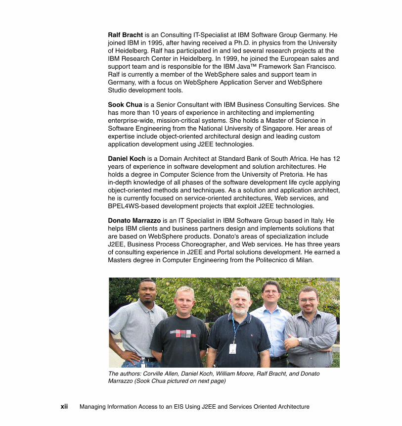
Ralf Bracht is an Consulting IT-Specialist at IBM Software Group Germany. He joined IBM in 1995, after having received a Ph.D. in physics from the University of Heidelberg. Ralf has participated in and led several research projects at the IBM Research Center in Heidelberg. In 1999, he joined the European sales and support team and is responsible for the IBM Java™ Framework San Francisco. Ralf is currently a member of the WebSphere sales and support team in Germany, with a focus on WebSphere Application Server and WebSphere Studio development tools.
Sook Chua is a Senior Consultant with IBM Business Consulting Services. She has more than 10 years of experience in architecting and implementing enterprise-wide, mission-critical systems. She holds a Master of Science in Software Engineering from the National University of Singapore. Her areas of expertise include object-oriented architectural design and leading custom application development using J2EE technologies.
Daniel Koch is a Domain Architect at Standard Bank of South Africa. He has 12 years of experience in software development and solution architectures. He holds a degree in Computer Science from the University of Pretoria. He has in-depth knowledge of all phases of the software development life cycle applying object-oriented methods and techniques. As a solution and application architect, he is currently focused on service-oriented architectures, Web services, and BPEL4WS-based development projects that exploit J2EE technologies.
Donato Marrazzo is an IT Specialist in IBM Software Group based in Italy. He helps IBM clients and business partners design and implements solutions that are based on WebSphere products. Donato's areas of specialization include J2EE, Business Process Choreographer, and Web services. He has three years of consulting experience in J2EE and Portal solutions development. He earned a Masters degree in Computer Engineering from the Politecnico di Milan.
The authors: Corville Allen, Daniel Koch, William Moore, Ralf Bracht, and Donato Marrazzo (Sook Chua pictured on next page)
xii Managing Information Access to an EIS Using J2EE and Services Oriented Architecture

Author: Sook Chua
Thanks to the following people for their contributions to this project:
Tamas VilaghyITSO, Poughkeepsie Center
Sam KaipaIBM Burlinghame
Andrew GardnerIBM Australia
Become a published authorJoin us for a two- to six-week residency program! Help write an IBM Redbook dealing with specific products or solutions, while getting hands-on experience with leading-edge technologies. You'll team with IBM technical professionals, Business Partners or customers.
Your efforts will help increase product acceptance and customer satisfaction. As a bonus, you'll develop a network of contacts in IBM development labs, and increase your productivity and marketability.
Find out more about the residency program, browse the residency index, and apply online at:
ibm.com/redbooks/residencies.html
Preface xiii

Comments welcomeYour comments are important to us!
We want our Redbooks™ to be as helpful as possible. Send us your comments about this or other Redbooks in one of the following ways:
� Use the online Contact us review redbook form found at:
ibm.com/redbooks
� Send your comments in an email to:
� Mail your comments to:
IBM® Corporation, International Technical Support OrganizationDept. HZ8 Building 662P.O. Box 12195Research Triangle Park, NC 27709-2195
xiv Managing Information Access to an EIS Using J2EE and Services Oriented Architecture

Part 1 Scenario introduction
This part of the book introduces the sample scenario that we use to illustrate EIS integration issues.
Part 1
© Copyright IBM Corp. 2005. All rights reserved. 1

2 Managing Information Access to an EIS Using J2EE and Services Oriented Architecture

Chapter 1. Introduction to this book
This chapter discusses what the team tried to achieve with this redbook. It explains the audience for this book in detail and how you should read this book if you are interested in any of the various technologies and aspects covering EIS integration.
1
© Copyright IBM Corp. 2005. All rights reserved. 3

1.1 Who should read this bookIntegrating to an EIS is not a trivial exercise. You probably have come to appreciate the complexity of this process if you have gone through similar exercises in your organization. Most organizations have enterprise architectures, including principles, frameworks, and components for their EIS integrations. Whether these architectures are actually used across the enterprise by the different development channels or development teams is another debate. However, the real challenge is whether your organization or channel EIS integration methodologies are working for or against you.
For example, ask yourself these questions about your EIS integration architecture:
� Is it easy to maintain?
� Is it developer friendly?
� Is it a disciplined development environment?
� Does it perform fast?
� Does it abstract your EIS integration from your business processes?
� Can you add new connectors?
� Can you change from a CICS® or COBOL transaction to a JDBC-stored procedure without affecting the business process?
� Can your business processes invoke an EIS transaction and be totally agnostic as to where the EIS is located?
� Can your business processes invoke an EIS transaction and be agnostic to any connector that is used for the integration?
� How are your business processes or applications affected when you change a back-end transaction? Does it require extensive re-factoring to your processes and/or applications?
� Do you have questions on which technologies you can or should use for your EIS integration (for example, J2C connectors, JDBC, JMS, Web services, BPEL processes, and so on). Importantly, what is the right fit for your organization?
If any of these questions relate to your situation and the challenges that you face in your environment then the information in this book will be helpful to you.
Architects, designers, and developers of all skills will benefit by reading some of the chapters in this book. Part 1, “Scenario introduction” on page 1 covers the architecture, business scenario, design, and environment. Architects and designers should read all of the chapters in this part of the book. Developers can
4 Managing Information Access to an EIS Using J2EE and Services Oriented Architecture
also benefit from these chapters because they present an overview of the architectural challenges, concepts, vision, and objectives that influenced the architecture for our EIS integration scenarios.
Part 2, “Development example” on page 93 implements an EIS integration solution, using J2EE, Web services, J2C connectors, JMS, and BPEL processes into a real-world EIS running IMS™ and CICS and Cobol transactions. This part of the book is for designers and developers who want to see how the architecture was implemented using technologies and development tool sets, such as WebSphere Studio Application Developer Integration Edition.
1.2 What we do in this bookIn this redbook, we modelled our EIS integration architecture and design from the use cases of a fictitious stock trading firm that is called ITSO Trading Firm. The ITSO Trading Firm must integrate with various back-end EIS systems to successfully processes its business processes. We focussed on architecture for the ITSO Trading Firm’s EIS integration requirements, using standard technologies such as J2EE, JMS, Web services, and J2C. (See 2.3, “Key technologies” on page 58 for descriptions of some of the key technologies that we used in our EIS integration architecture.)
Proof points for our EIS integration solution were:
� EIS integration using J2C connectors
– CICS connector
– IMS connector
� EIS integration to a remote EIS
– Creating an EIS integration adapter using JMS that uses the J2C connector for EIS integration.
– Using Web services to access an external EIS
� Using BPEL processes
– Creating processes using WebSphere Studio Application Developer Integration Edition
– Running BPEL processes in Business Process Choreographer
� Transaction management
– Managing a unit of work across activities in a BPEL process
– Performing compensation on a BPEL activity
Chapter 1. Introduction to this book 5

� Security
– Securing the EIS integration
� Using J2EE
� Using the WebSphere Business Integration adapter framework in WebSphere Business Integration Server Foundation to connect and to run transactions against a database
With the focus on EIS integration using J2EE, SOA, and Web services, we created an architecture for our EIS integration. Using this architecture, we then designed and implemented our EIS integration services, processes, and components.
1.3 How to use this bookThis redbook consists of two parts.
Part 1, “Scenario introduction” on page 1 covers the following:
� The architecture of our EIS integration in Chapter 2, “Architecture” on page 9
� The business scenarios and design of the EIS integration architecture in Chapter 3, “Scenario overview and design” on page 65
� The environment setup in Chapter 4, “Environment” on page 87
Part 2, “Development example” on page 93 provides details about our implementation of the EIS integration design. (See 2.3, “Key technologies” on page 58 for descriptions about some of the key technologies that we used in the EIS integration architecture.) We implemented Web services, BPEL processes, and components.
If you have an immediate technology or implementation question, you can begin with Part 2, “Development example” on page 93. Here, you can find the implementations of the services, processes, and components, and you can read about how we used the J2C connectors to connect to the back-end EIS system.
However, to get the greatest benefit from this redbook, you should first read Part 1, “Scenario introduction” on page 1. Reading though this first part of the book will give you a clear view of what we set out to build and how we built it. The
Note: This redbook does not discuss EAI using WebSphere Business Integration for integration of data, applications, or processes. Instead, it focusses on integrating to a back-end EIS, using J2EE, J2C, JMS, and Web services.
6 Managing Information Access to an EIS Using J2EE and Services Oriented Architecture

chapters in Part 1, “Scenario introduction” on page 1 might trigger some thoughts and challenges that you should consider in your organization. EIS integration is not a trivial task. There are many challenges that you must consider before you start using the technologies available to you.
After you have read Part 1, “Scenario introduction” on page 1, look at the different chapters in Part 2, “Development example” on page 93 to get an understanding of how we implemented the EIS integration solution. Some of the detailed implementations have been covered in other IBM Redbooks. Where appropriate, we reference those redbooks that have already covered the detailed implementation options, particularly those that discuss how to create a Web service or how to create a BPEL process in WebSphere Studio Application Developer Integration Edition. Do not be concerned that you might have to move from one redbook to the other to understand the implementations. The chapters in Part 2, “Development example” on page 93 provide enough implementation details for you to understand how we have implemented our EIS integration solution.
To see where all the services and components are put together into Business Process Choreographer, see Chapter 9, “Integration into business processes” on page 241. If you are interested in business process management, in particular BPEL processes and Business Process Choreographer, then this chapter will be helpful to you.
Chapter 1. Introduction to this book 7

8 Managing Information Access to an EIS Using J2EE and Services Oriented Architecture

Chapter 2. Architecture
Integration to a back-end EIS requires a detailed analysis of technology options and architectural issues so that you can create an EIS integration architecture that can support changing systems and infrastructures. This chapter illustrates and discusses the meta, conceptual, and logical architecture for our EIS integration solution, including the patterns and components that we created and used for the architecture.
2
© Copyright IBM Corp. 2005. All rights reserved. 9

2.1 Integrating a remote EISMost companies today have some sort of a back-end EIS that processes business transactions and maintains business data in a database. Examples of a corporate EIS are:
� Enterprise Resource Planning (ERP) systems (for example, SAP)� A CICS and IMS system running business transactions� A corporate database running SQL stored procedures � A corporate database storing company data� A combination of some or all of these scenarios
To further complicate the integration for architects and designers, any or all of the enterprise information systems can be either:
� Remote
The back-end system is geographically remote to the application or business processes integrating with the back-end system. An example of such a scenario is where an application server is running an application in Minsk, Belarus, and the back-end system that processes the transactions is in Johannesburg, South Africa. In this scenario, where a back-end system is remote to an application or business process, the back-end typically would be accessed over a wide area network (WAN) or over the Internet.
� Local
The back-end system is located on the same local area network (LAN) as the application or business processes.
� External
A remote back-end system where an application or business process must integrate with an external company’s back-end system. An example of this scenario would be an external company that provides a stock portfolio analysis service.
Why is it so difficult for IT developers and project teams to integrate with back-end systems? From a conceptual point of view, you can architecturally model two systems with defined boundaries, layers, and interfaces. So, conceptually a Web application that is running a company’s call center should be able to integrate with its back-end system effortlessly, correct?
Well, conceptually, yes. However, if you analyze the two systems, you would find that the company’s call center was implemented using a proprietary language or tool set, while the back-end was implemented with another language (for example CICS / COBOL). There are almost an infinite amount of EIS integration scenarios.
10 Managing Information Access to an EIS Using J2EE and Services Oriented Architecture

Developers have different skills and levels of experience. When you start on a new project (or even a maintenance project), depending on how your organization structures and staffs new projects, you can end up with a project team of mixed levels of experience and technical skills. You might have a few good J2EE developers, but the back-end system that you need to integrate with, was (or is being) developed using CICS / COBOL. Usually, it will be a case of the application and processing layers being developed in one language and tool set other than the back-end system transactions. You then have developers sitting on different sides of the fence, talking different languages to describe their interfaces.
For example, lets say the Java developer needs to send a field that represents an amount to the back-end system. Typically the Java developer will use a Java type such as BigDecimal to represent the amount and will define the same amount field in a COBOL copy book as a S9(13)V99 COMP-3 field. Translating from a Java BigDecimal type to a COBOL S9(13)V99 COMP-3 type is not an easy task. The challenge for developers here is really how to create a request that meets the contract definition of the EIS (a request record) and how to parse the response from the EIS (a response record) into an object or component that the application or business process can handle. At the same time, you must consider how you will connect to the back-end system. In addition, you should consider quality-of-service issues such as transaction management, security, and connection pooling.
Fortunately, specifications and technologies exist that help with back-end integration requirements. However, using technologies or development tool sets alone just for the sake of solving back-end integration challenges might not adhere to your organization’s IT standards and principles. In addition, it probably will not meet the expectations of your business unit or customers in the long run.
There are many issues to consider before you start plugging in the available technology options. Some of the issues are known, and some you will probably discover as you start unit and integration testing with back-end transactions. For example, have you thought about what impact versioning will have on your applications and business processes when you start re-factoring the interfaces of your back-end transactions? In reality, business requirements do change, sometimes as late as the testing phase. If you are on the critical-path of a project and you need to change back-end transactions, then you want to have a back-end integration solution that can handle these type of changes with minimal impact.
Chapter 2. Architecture 11

Consider the skill level of your project team, standards and principles of your IT organization, and last but not least, expectations from your business units or customers. If you do not have an architecture for your back-end integration solution, then your development (or maintenance) project might not adhere to your organization’s or customers’ IT standards and principles and might not meet the expectations of your business unit.
2.1.1 Levels of EIS integrationArchitects and designers have designed and successfully implemented different back-end integration solutions for many years. Chances are good that there are still production systems running in many companies today that integrate with a back-end system that is running CICS / COBOL, through SNA, using APPC. In these environments, it is likely that the company has created a framework for their back-end integration requirements. A common approach used by such frameworks is to create a request record and to parse a response record using connection management.
The way that applications were architected, designed, and constructed in the past (the “client/server era”) is quite different from how we perform those tasks in the era of the Web. Even now, when we talk about on demand computing and creating composite applications using services-based architecture styles, our architectures, designs, and implementations probably will be quite different in the future.
There are three different levels of back-end systems integration:
� Applications directly to a back-end system� Applications to a EIS integration component and service� Applications to a EIS system process
Figure 2-1 on page 13 illustrates these three levels.
12 Managing Information Access to an EIS Using J2EE and Services Oriented Architecture

Figure 2-1 Levels of EIS integration
Logical architecture layersThe architecture layers in Figure 2-1 illustrate the different levels of back-end system integrations. These architecture layers represents a logical view of an enterprise’s layered architecture. We acknowledge that every enterprise probably has its own layered architecture that adheres to its own naming standards and the principles of its IT department. These logical layers represents a general (or abstract) view for discussion and illustration of the different levels of back-end integration. Most enterprises probably have many channels or business units. Often, you will find that channels have implemented their own applications, using their own EIS integration frameworks, patterns, and components.
Illustrates that components are exposed as services
Illustrates an interface
PresentationApplication
PresentationProcess
PresentationEIS
PresentationComponentsLogi
cal A
rchi
tect
ure
Laye
rs
Level 1Level 2
Level 3
PresentationPresentation
Chapter 2. Architecture 13

The levels of EIS integration should not be seen as levels of maturity or technical capabilities of any particular organization. The levels illustrate the different styles for EIS integration and set the scene for the architecture that we propose in this redbook.
Table 2-1 gives a description for the logical layers that the diagrams in this redbook use.
Table 2-1 EIS integration architecture layer descriptions
Level 1, application to EISBefore the J2C specification was created many project teams used the Common Connector Framework (CCF) from IBM to integrate with back-end systems. In some instances, developers created their own legacy frameworks using sockets and proprietary protocols between their applications and a corporate back-end system.
Layer Description
Application Represents the business-facing solution which consumes services from one or more providers and integrates those solutions into the application- or channel-specific business processes or presentations.
Process Where enterprise business processes are exposed as services that can be used by applications or other enterprise business processes. Enterprise processes are exposed using a service-based architecture style. The process layer can contain:
� Enterprise business processes
– Create and maintain customer– Buy and sell stock– And so on
� System processes
– EIS connectivity process– Security service
� Utility processes
Components The various components that support the implemented processes, the business objects, and their implementations.
EIS Back-end data processing or transactions systems.
14 Managing Information Access to an EIS Using J2EE and Services Oriented Architecture

This level of integration is typically where the application layer integrates directly with a back-end system. An application in this context could be a Swing-based J2SE application running on a desktop or a Web-based application running in a Web application server. It can be argued that the application is using a component. For example, it could use a managed or non-managed J2C connector component. In this case, why then does the level 1 line in Figure 2-1 on page 13 not connect to the component layer? With a level 1 integration style, the component (be it a CCF or J2C component) is part of the application, either explicitly or implicitly. An application could use a component for its back-end integration requirements, but that component is part of the application.
Table 2-2 lists the benefits and drawbacks of EIS integration at level 1.
Table 2-2 Benefits and drawbacks of EIS integration at level 1
Level 2, application to J2C component and serviceThis level of back-end integration is where an application starts to use a J2C component that has been exposed as a service that is using Web services technology. An example of such a level of integration is where you expose your back-end transactions as services, using J2C connectors. (See Chapter 3: Building CICS ECI enterprise services in the IBM Redbook Exploring WebSphere Studio Application Developer Integration Edition V5, SG24-6200 for detailed step-by-step instructions on how to create a service from a J2C connector.)
Benefits Drawbacks
The development team can extend or re-factor the implementation requirements (for example, by compressing records over the WAN).
Implementation is open to everyone in the team.
There is direct control over security aspects.
There are few incentives to formalize interfaces.
Component reuse across channels is implemented by copy and paste.
Reuse of enterprise business processes across channels is difficult to achieve. There is a strong possibility that different channels are implemented to different back-end integration frameworks.
Chapter 2. Architecture 15

Any application can invoke the J2C service using its generated proxies and stubs. With a back-end integration at level 2, the focus is on exposing EIS integration components as services, using Web services technology in a service-based architecture. With a level 2 EIS integration, the EIS component and service is not part of the application or business process.
Table 2-3 lists the benefits and drawbacks of EIS integration at level 2.
Table 2-3 Benefits and drawbacks of EIS at integration level 2
Level 3, application to EIS system processThe next level of back-end integration is where an application invokes a business process, or rather a system process, to handle its back-end integration. Figure 2-2 on page 17 illustrates a more detailed view of this level of EIS integration.
Benefits Drawbacks
There is a separation of provider and consumer.
Services that are remote to consumers can impact service level agreements.
The implementation is hidden from the consumer.
There is versioning and testing across multiple channels.
Interfaces must be formalized. Services that are a direct reflection of an existing interface may not be sufficiently abstracted away from the implementation to provide any real notion of loose coupling.
You can reuse services across channels, not components by copy and paste.
It can require a high level of understanding of the implementation for service consumer to correctly use the service.
It enables loose coupling, at least in a platform dependency sense.
The granularity of the existing interface may not match the new requirements.
Taxonomy and semantic issues must be resolved.
16 Managing Information Access to an EIS Using J2EE and Services Oriented Architecture
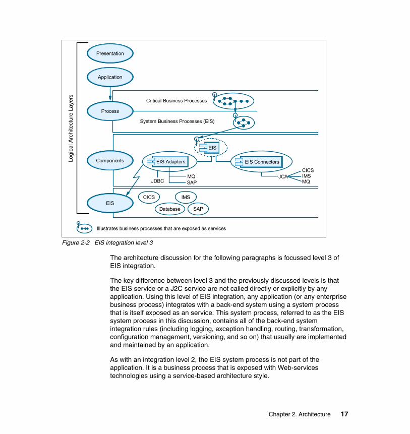
Figure 2-2 EIS integration level 3
The architecture discussion for the following paragraphs is focussed level 3 of EIS integration.
The key difference between level 3 and the previously discussed levels is that the EIS service or a J2C service are not called directly or explicitly by any application. Using this level of EIS integration, any application (or any enterprise business process) integrates with a back-end system using a system process that is itself exposed as an service. This system process, referred to as the EIS system process in this discussion, contains all of the back-end system integration rules (including logging, exception handling, routing, transformation, configuration management, versioning, and so on) that usually are implemented and maintained by an application.
As with an integration level 2, the EIS system process is not part of the application. It is a business process that is exposed with Web-services technologies using a service-based architecture style.
Illustrates business processes that are exposed as services
PresentationApplication
PresentationProcess
PresentationEIS
PresentationComponentsLogi
cal A
rchi
tect
ure
Laye
rs Critical Business Processes
System Business Processes (EIS)
PresentationPresentation
JDBCMQSAP
JCACICSIMSMQ
EIS Adapters
EIS
EIS Connectors
CICS IMS
SAPDatabase
Chapter 2. Architecture 17

The EIS system process can be implemented using BPEL and Business Process Choreographer. (See 2.3, “Key technologies” on page 58 for discussion on BPEL and Business Process Choreographer.)
Notice that Figure 2-2 on page 17 illustrates some components, such as the EIS component and the EIS connector components. More detail on the architecture of EIS system process and the EIS components is discussed in 2.2, “Architecture discussion and best practices” on page 19.
Figure 2-3 further illustrates this level of EIS integration.
Figure 2-3 EIS integration level 3, view of processes and components
In Figure 2-3, notice that with an EIS integration of level 3 that an application’s business processes integrate with a back-end system using the EIS integration system process. illustrates a typical business process that implements the Get Company List use case. It must integrate with a back-end system to get a list of companies, and then given certain criteria, it must get the detail for a specific company.
Critical Business Processes (Company List)
System Process (EIS Integration)
Invoke EIS System BP
EIS Component Partner Link
EIS ConnectorsJCA
CICSIMSMQEIS Adapters
MQCICSSAPetc.
JDBC
EIS
18 Managing Information Access to an EIS Using J2EE and Services Oriented Architecture

In this scenario, the same EIS system process gets invoked for every back-end integration or transaction. Instead of the application, or in this scenario, the business process, calling a service-enabled J2C connector explicitly from the critical business process, it delegates the back-end integration handling to another system process. It is the responsibility of this system process to facilitate back-end integration to any back-end system for all applications or critical business processes.
Notice that the business processes are themselves exposed as services and that the EIS component is also exposed as a service. This architecture is discussed in detail in 2.2, “Architecture discussion and best practices” on page 19.
Table 2-4 lists the benefits and drawbacks of EIS integration at level 3.
Table 2-4 Benefits and drawbacks of EIS integration at level 3
2.2 Architecture discussion and best practicesThis section discusses the architecture for the ITSO Trading Firm. See Chapter 3, “Scenario overview and design” on page 65 for a detailed discussion of the ITSO Trading Firm use cases and scenarios.
2.2.1 Architecture challengesEvery architect or designer, when challenged with a new business problem, will try to create an architecture that adheres to common architecture principles, such as extensibility, stability, scalability, portability, flexibility, and so on. One can argue that the architects of a high-rise building must consider possible disaster scenarios such as earthquakes, high winds, thunderstorms, and so on. Likewise,
Benefits Drawbacks
There is an increasingly graphical, declarative development approach.
Enterprise services and processes require organizational changes to process, architecture, and infrastructure.
It is driven by business process. It is difficult to define ownership of the EIS system process.
The EIS integration process is completely abstracted from business process.
There is a dictatorship in that all channels must use the EIS system process.
There is a shift to an on demand operating environment by virtualizing the back-end implementations.
There is a reduced effort to code.
Chapter 2. Architecture 19

software architects attempt to design a robust software system that not only exceeds the business expectations but that also adheres to architecture and software design principles.
Imagine for a moment that you are an architect of a high rise building in downtown Johannesburg, South Africa. What are some of the challenges you face? In this location, there are natural challenges, such as earthquakes, thunderstorms, and high winds, as well as man-made challenges, such as adequate parking and access to the building. As the architect, you must consider all the challenges in your final blue print. Software architects should apply the same theory when designing new software systems.
As discussed in previous sections of this chapter (see 2.1, “Integrating a remote EIS” on page 10), back-end system integration can be very complex. Back-end system integration presents its own set of unique, and common, architectural issues that must be considered when creating a software solution that exceeds business expectations while at the same time adhering to IT principles.
Wide area network (WAN)The application or business process that must integrate with a back-end system can be physically remote from the back-end. (See 2.1, “Integrating a remote EIS” on page 10 for descriptions of local, remote, and external back-end systems.) When your application must integrate with a back-end system over the WAN, you have to consider the available bandwidth.
For example, if your available bandwidth is 64 KB and you share SNA and IP traffic over the same physical infrastructure, then you would definitely want to consider using compression between your application and the back-end system. The fact that you maybe have a 256 KB, or even 1 MB, link available between your application and the back-end system should not mean that you can push XML documents over the WAN.
Consider, for example, that over time the volume and concurrency of transactions to the back-end system might increase. You might have designed elegant solutions on the application and back-end integration layers. However, the WAN might void all that effort if it cannot handle the volume.
Suggestion: Consider designing a back-end integration solution where you can declaratively enable or disable data compression to a back-end system over the network. For example, using the J2C CICS connector, you can specify security classes. These classes can handle the compression of requests to the back-end system and the decompression of responses from the back-end. Figure 2-4 illustrates how to configure J2C CICS connector security classes that are used for data compression.
20 Managing Information Access to an EIS Using J2EE and Services Oriented Architecture

Figure 2-4 Defining J2C CICS connector security classes for compression
Transaction managementA key service that is required for robust server-side development is transactions. Transactions, when used properly, can make your mission-critical operations run predictably in an enterprise environment. Transactions are an advanced programming paradigm that allow you to write robust code. Transactions are also very useful constructs to use when performing persistent operations, such as updates to a database.
Distributing your application or business processes across the network introduces failure and reliability concerns. For example, what happens if the network crashes during a banking operation? Typically, an exception will be generated and thrown back to the client code. However, this exception is quite ambiguous in nature. The network may have failed before money was withdrawn from an account. It is also possible that the network failed after the withdrawal. There is no way to distinguish between these two cases. All the client code sees is a network failure exception. Thus, we can never know for sure how much money is in the bank account.
Chapter 2. Architecture 21

In fact, the network may not be the only source of problems. Because we're dealing with bank account data, we are dealing with persistent information that resides in a database. It is entirely feasible that the database itself could crash. The machine on which the database is deployed could also crash. If a crash occurs during a database write, then the database could be in an inconsistent, corrupted state.
For a mission-critical enterprise application, none of these situations is acceptable. Mainframe systems and other highly available systems offer preventive measures to avoid system crashes. In reality, however, nothing is perfect. Machines, processes, or networks will always fail. There needs to be a recovery process that can handle these crashes.
In 2.1.1, “Levels of EIS integration” on page 12, we discuss the different levels of EIS integration and, in particular, focus on level 3 integration where the application or business processes use an EIS system processes for all of its back-end integration requirements. In the domain of processes, or more specifically BPEL and Business Process Choreographer, transactional behavior depends on the interoperability of the process. (See 2.3, “Key technologies” on page 58 for definitions of BPEL and Business Process Choreographer.)
Non-interruptible processes execute within a single transaction. In contrast, each activity within an interruptible process can have its transactional behavior set. In either case, if a failure is detected, the current uncommitted transaction is rolled back, and any pending compensation activities are applied.
InteroperabilityA major benefit of Web services is interoperability between heterogeneous platforms. To get the maximum benefit, you want to design your services to be interoperable with clients on any platform. The Web Services Interoperability (WS-I) organization helps in this regard. WS-I promotes a set of generic protocols for the interoperable exchange of messages between Web services. The WS-I basic profile promotes interoperability by defining and recommending how a set of core Web services specifications and standards (including SOAP, WSDL, UDDI, and XML) can be used for developing interoperable Web services.
Using Web services does not imply that you will achieve interoperability by default. For example, if your EIS system process is exposed as an enterprise service, then you must consider that consumers of your EIS system service can run on a .NET platform, or even a Siebel or SAP system for that matter. Your development tool set, such as WebSphere Studio Application Developer Integration Edition, has the ability to generate services that are WS-I compliant, but it can also generate service bindings that are not supported by the WS-I
22 Managing Information Access to an EIS Using J2EE and Services Oriented Architecture

basic profile 1.0 specification. For further information about WS-I Basic Profiles, see:
http://www.ws-i.org
Parameters for Web service calls can be standard Java types and objects. However, the type of the parameter that you use has a significant effect on the portability and interoperability of your service. Specifically, be careful when passing XML documents as parameters. Because of portability limitations, you should avoid passing parameters that require the use of vendor-specific serializers or deserializers.
VersioningYou must include support for versioning in your back-end system architecture from the beginning. You do not want to re-factor your design or implementation, or worst case scenario your architecture, to support versioning after you have deployed your system into production. You want to be able to plug-in (programmatically or declaratively) new versions of components, new versions of EIS connectors, and new feature classes (see “EIS integration feature classes” on page 40 for a discussion on feature classes).
You also want to be able to integrate with new versions of CICS / COBOL copybooks, while at the same time still supporting older versions. This scenario typically occurs when you want to introduce a new release to an application or process, while the remainder of the production applications continue to use the older version. When you have an enterprise service, then all of your channels use that service, or viewed differently, all of your enterprise business processes use your EIS system service. By changing that service, you risk affecting your service level agreements.
If you pilot a change in your EIS system process to a specific business process or channel application, you can minimize that risk. However, doing so means that you have to consider building versioning support into your architecture. When you introduce new changes or extensions to your applications or critical business processes, you would probably pilot the new release to a selected group of channels, applications, branches, users, or the requirements you have from your business units or customers. Because all channel applications can potentially call the same critical business processes, you must build support for versioning into your EIS system process. This support caters to the piloting and rollout scenarios where you do not have a big-bang approach when you introduce changes into a production environment.
Chapter 2. Architecture 23

PerformanceIt is obvious that your architecture, when finally designed and implemented, must perform fast. Consider that by introducing additional logical layers, or even physical tiers, you have a very real possibility of impacting any service level agreement (SLA). Be watchful for Yet Another Decoupling Layer (YADL), and be mindful of the blame-game when performance suffers and response time SLAs are not met.
Suggestion: Consider adding time stamps to your logical layers and physical tiers. For example, if your EIS system service performs poorly, is the problem caused by bad connection pooling with too many concurrent service requests, or is the problem occurring on the WAN, perhaps within the request and response handling in the interaction layer of the service end-point? Alternately, maybe the problem is caused by a back-end system routine that is running very slowly.
The ability to have this type of information available will greatly assist you when you re-factor for performance or when you enter the inevitable blame-game in a critical situation (critsit) meeting over poor performance. Try to design and build this capability into your solution from the beginning. Do not attempt to re-factor your EIS integration solution after construction.
You must at least have time stamps for:
� The total time of the EIS system process
� Total time spent in the service end-point interaction layer
� Total time spent in the service end-point processing layer
The EIS service end-point processing layer is the EIS system process.
� Total time spent in the EIS component
� Total time to create a back-end request byte buffer
� Total time to execute a J2C javax.resource.cci.Interaction
Usually you can view this time as the time spent in the network (LAN or WAN) plus the execution time of the back-end transaction. If, for example, the back-end systems team says that the back-end transaction execution time was 500ms but this time indicates 3000ms, then you can assert that the other 2500ms was either the network (likely) or the J2C connector (less likely).
� Total time to parse a back-end response byte buffer
If you have these time stamps available, you can focus on the layers or components that are causing bad responses when you have these type of issues with your back-end integration architecture.
24 Managing Information Access to an EIS Using J2EE and Services Oriented Architecture

Error handling and reportingBecause Web services are not immune from errors, you must decide how to throw or otherwise handle exceptions or errors that occur. You need to address such issues as whether to throw service-specific exceptions or whether to let the underlying system throw system-specific exceptions. You must also formulate a plan for recovering from exceptions in those situations that require recovery. Just like any Java or J2EE application, an EIS service may encounter an error condition while processing a client request. The EIS service needs to properly catch any exceptions thrown by an error condition and propagate these exceptions.
With a J2EE or Java application that is not a Web service or BPEL process, you can propagate exceptions up the call stack until reaching a method with an exception handler that handles the type of exception thrown. You can continue to throw exceptions up the entire stack trace. You can also write exceptions that extend or inherit other exceptions. However, the EIS service and BPEL process have additional constraints that impact the design of the EIS system service.
Consider the following when designing your error reporting and exception handlers:
� Wrap application-specific errors and exceptions into meaningful service-specific exceptions and throw these service-specific exceptions to the clients.
� Exception inheritances are lost when you throw a service-specific exception.
� The exception stack trace is not passed to the client.
� The EIS system process must have an exception handler to log system and application specific errors and to return a meaningful fault to consuming business processes and applications.
Chapter 2. Architecture 25

ManagementOnce we get to runtime, then we need to manage the EIS services. You need to consider:
� Runtime service management
– Access– Billing
� Monitoring the EIS service
– SLA– Consumers
� Provide feedback mechanism
– SLA compliance– Performance– Availability
Suggestion: Consider adding a stack trace property for all of your system exceptions to help you in finding problems.
try {...
} catch (SomeException e) {// get the stack traceStringWriter sw = new StringWriter();PrintWriter pw = new PrintWriter(sw);e.printStackTrace(pw);
// create service faultMyComponentException fault = new MyComponentException(e.getMessage());fault.set_stackTrace(sw.getBuffer().toString());
// throw the service faultthrow fault;
}
Having the actual stack trace available where the system exception occurred in a multi layered architecture will help you to immediately focus exactly where the problem happened. You must be able to identify which component, which BPEL activity, or which service caused the system problem.
This capability probably is not required for your business exceptions, like a FundsNotAvailable exception.
26 Managing Information Access to an EIS Using J2EE and Services Oriented Architecture

Figure 2-5 illustrates the service management concept.
Figure 2-5 EIS service management
SecuritySecurity is a major consideration for multi-tier deployments. In integrating with back-end systems, J2EE components might use different security mechanisms and operate in different protection domains than the resources they access. In these cases, the calling container can be configured to manage the authentication to the resource for the calling component. This form of authentication is called container-managed resource manager sign on.
The J2EE architecture also recognizes that some components require an ability to manage the specification of caller identity and the production of a suitable authenticator directly. For these applications, the J2EE architecture provides a means for an application component to engage in what is called application-managed resource manager sign on. Application-managed resource manager sign on is used when the ability to manipulate the authentication details is a fundamental aspect of the component’s functionality.
You should ensure that access to any component that encapsulates or is provided by its container with a capability to sign on to another resource is secured by appropriate authorization rules.
Need to manage relationship ofconsumers to Web Services
Need to manage relationship ofEIS Service to implementation(s)
ConsumingApplication or
Business ProcessService
ImplementationEIS
Service
Chapter 2. Architecture 27

In a distributed computing system, a significant amount of information is transmitted through networks in the form of messages. Message content is subject to three main types of attacks. Messages might be:
� Intercepted and modified for the purpose of changing the affects they have on their recipients.
� Captured and reused one or more times for the benefit of another party.
� Monitored by an eavesdropper in an effort to capture information that would not otherwise be available.
You can minimize such attacks by using integrity and confidentiality mechanisms.
Domain objectsEvery application has data items that logically belong and typically are used together. It is programmatically convenient and, with enterprise beans, performance enhancing to treat this logical group of data items as a separate object. These type of objects are also commonly known as value objects, and some texts even refer to it as data transfer objects. If Java had a structure construct, such as C/C++ and many other languages do, a domain object would be a structure.
Using domain objects is useful for communication across the layers of your architecture, and it is a well known and documented pattern. The real importance here is that you are creating an enterprise back-end integration service that uses enterprise components for back-end system integration.
Refer to 2.1.1, “Levels of EIS integration” on page 12 for an illustration and discussion that details the different levels of back-end system integration levels. When you create domain objects you must ideally have an enterprise data model that describes your enterprise. If you work for an organization that has many different business units, chances are good that every business unit has a different view of their customers and products.
A customer of the home loans business unit could potentially be described differently than the customer of the vehicle and asset finance business unit. For example, let’s say you have a schema describing your customer. Is it really
Note: Message Driven Beans do not receive the security identity of the producer who sends the message, because there is no standard way to stick security information into a Java Message Service (JMS) message. Therefore, you cannot perform Enterprise JavaBeans (EJB) security operations with Message Driven Beans.
28 Managing Information Access to an EIS Using J2EE and Services Oriented Architecture
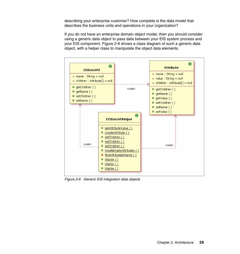
describing your enterprise customer? How complete is the data model that describes the business units and operations in your organization?
If you do not have an enterprise domain object model, then you should consider using a generic data object to pass data between your EIS system process and your EIS component. Figure 2-6 shows a class diagram of such a generic data object, with a helper class to manipulate the object data elements.
Figure 2-6 Generic EIS integration data objects
Chapter 2. Architecture 29
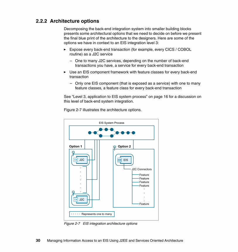
2.2.2 Architecture optionsDecomposing the back-end integration system into smaller building blocks presents some architectural options that we need to decide on before we present the final blue print of the architecture to the designers. Here are some of the options we have in context to an EIS integration level 3:
� Expose every back-end transaction (for example, every CICS / COBOL routine) as a J2C service
– One to many J2C services, depending on the number of back-end transactions you have, a service for every back-end transaction
� Use an EIS component framework with feature classes for every back-end transaction
– Only one EIS component (that is exposed as a service) with one to many feature classes, a feature class for every back-end transaction
See “Level 3, application to EIS system process” on page 16 for a discussion on this level of back-end system integration.
Figure 2-7 illustrates the architecture options.
Figure 2-7 EIS integration architecture options
EIS System Process
Option 1
EIS
Option 2
J2C Connectors
FeatureFeatureFeatureFeature
Feature
.
.
.
.
.
.
.
.
.
.
.
. . . . . Represents one to many
J2C
J2C
30 Managing Information Access to an EIS Using J2EE and Services Oriented Architecture

Benefits and drawbacks of the two architecture optionsTable 2-5 and Table 2-6 on page 32 list the benefits and drawbacks for the following architecture options:
� Option 1: many J2C services, a service for every back-end transaction
� Option 2: an EIS component framework that uses feature classes, one EIS component service with many feature classes
Table 2-5 EIS integration option 1: many J2C connector services
Benefits Drawbacks
Excellent development tools support in WebSphere Studio Application Developer Integration Edition.
Potential to end up with J2C services for every back-end transaction. Difficult to maintain in a development environment with developers of different skills and levels of experience.
Depending on the developer’s (or project team) experience and skill level, it is relatively easy to expose a back-end transaction as a J2C service. The steps to create the J2C service are well documented and easy to follow (see Chapter 3: Building CICS ECI enterprise services in the IBM Redbook Exploring WebSphere Studio Application Developer Integration Edition V5, SG24-6200).
Generated services result in many artifacts being created in the development workspace that must be managed, maintained, and placed in source control.
Principles of SOA:• Technology neutral: endpoint
platform independence• Standardized: standards-based
protocols• Consumable: enabling automated
discovery and usage • Reusable: use of service, not reuse
copying of code and implementation• Abstracted: service is abstracted
away from the implementation
Skill set of developers. The tool support is excellent, and it abstracts a lot of the Web services technologies from the developers. However, developers can potentially introduce a new set of problems when re-factoring the original service definition and implementations (WSDL files, classes, projects, and so on).
Increased separation between consumers and providers.
Not a formalized structured development framework that facilitates a disciplined development environment for developers and project teams, across all channels in the enterprise.
Chapter 2. Architecture 31

Table 2-6 EIS integration option 2: EIS component framework and feature classes
Ability to map messages (including parts of the request and response message) graphically or by using development tools such as WebSphere Studio Application Developer Integration Edition. For example, if the process that you have created graphically invokes a J2C service, then you can graphically map the request and the response (that is, map from a business process variable to the J2C service variable).
The possibility exists that your organization can end up with hundreds or even thousands of J2C services for every back-end transaction. This scenario can create maintenance and management problems on another layer using another technology.
There is maintenance of exposed J2C services when back-end transaction contracts change (for example, changing a COBOL copy book).
Creates a false sense of security that the tool set does everything. In reality, production systems, including the back-end transactions, are dynamic (new business requirements) and complex (COBOL copybook re-defines).
Benefits Drawbacks
Component-based architecture. Proprietary framework that developers have to learn. (Although one can argue that creating implementations using a concrete framework requires very little understanding and learning from developers.)
Framework creating a disciplined development environment for developers (managing risk of in-experienced developers or project teams).
EIS component requires effort to analyze, design, and construct. Benefits are realized only after the EIS component has been created.
Benefits Drawbacks
32 Managing Information Access to an EIS Using J2EE and Services Oriented Architecture

The architecture for our back-end integration uses option 2 (EIS system process using EIS component framework and feature classes).
2.2.3 Components and SOAOne of the most important principles of SOA, and possibly the most widely misunderstood, is that of loose coupling. Today, development productivity is no longer the number one concern of IT management. This fact means either that the original software crisis has been fixed or that it has simply been overtaken by a new, more serious crisis — the crisis of adaptability. The crisis of adaptability moves the priority away from new development to integration and reuse. Table 2-7 and Table 2-8 on page 34 show the potential benefits and drawbacks of components without and with SOA.
Table 2-7 Components without SOA
Fewer artifacts (such as WSDL files, classes, deployment-descriptors, projects, and so on) that must be created and maintained. Only one feature class per back-end transaction.
The possibility exists that custom mappers classes might have to be created to map request messages to the EIS system process and response messages from the EIS system process. For example, a business process variable, or parts thereof, must be mapped into either a general data object or another type of object (variable) for the EIS system process. You might have to code this mapping in Java code (using a Java snippet), as opposed to using graphical mapping capabilities when graphically composing a process.
Maintains the benefits of SOA but with components (see“Components with SOA” on page 34).
Greater flexibility to change back-end integration. The EIS component can declaratively use a different J2C connector (for example, if a back-end transaction was changed from an IMS transaction to a JDBC stored procedure).
Benefits Drawbacks
Potential benefits Potential drawbacks
Economics of scale achieved from reusing available components.
Components are permanently assembled into applications. It is easier to plug-in than to unplug.
Software solutions are developed rapidly from existing components.
Lack of post implementation flexibility.
Choice of different components yields some pre-implementation flexibility.
Chapter 2. Architecture 33

Table 2-8 SOA with components
Components with SOAThe true potential of components and SOA only really comes when you have both of them. With both, you have:
� Components and services assembled with loose coupling and dynamic recoupling.
� Coherent service interfaces supported by flexible component-based application.
� Service-based approach applies both inside and outside the application.
� Scalable, flexible, on demand solutions.
2.2.4 Meta-architectureThe meta-architecture is a set of high-level decisions that strongly influenced the integrity and structure of the EIS system process and EIS component, but is not itself the structure of the overall back-end integration solution. The meta-architecture, through style, patterns of composition, principles, and philosophy, rules out certain structural choices, and guides selection decisions and trade-offs among others.
PrinciplesThe purpose of this meta-architecture is not to define the principles of a service orientation architecture style but rather to focus on the principles of the EIS process and component.
Potential benefits Potential drawbacks
Services developed rapidly from existing applications and packages.
Inflexibility behind service interface.
Opportunities for reuse and economics of scale.
Existing applications and packages preserve their legacy limitations.
Useful path towards further re-engineering.
Concerns about scalability and portability of implementation.
Re-engineering may never happen.
34 Managing Information Access to an EIS Using J2EE and Services Oriented Architecture
Key principles for the EIS integration process and component are:
� Stability through interfaces
– EIS system process and EIS component exposed as services, using a services-based architecture style
– A service is a window into a business process
� Optimize for the enterprise
– Enterprise services
– Enterprise processes
– Enterprise components
� Utilize standard technologies
– Services, processes and components must adhere to standards and specifications
� Component base architecture
� Use a framework
– The same approach as the Template Method design pattern, but applied on a much larger scale. Frameworks are concrete, not abstract.
Platform of compositionThe architecture is composed of logical layers and physical tiers. Figure 2-2 on page 17 shows a graphical view of the conceptual architecture layers from an enterprise perspective. The EIS system process and EIS component is implemented in the process and component layers, respectively. Table 2-1 on page 14 gives a description of the logical layers that our layered architecture uses.
VisionThe EIS service, process, and component should deliver on the SOA goals of business agility, on demand computing, loosely coupled components, processes, and services.
Note: OO design is more important than any particular implementation technology (such as J2EE or even Java). Good programming practices and sound OO design underpin good J2EE applications. Bad Java code is bad J2EE code. For more information, see Expert One-on-One J2EE Design and Development, Rod Johnson, ISBN: 0-7645-4385-7, also available at:
http://www.wrox.com/WileyCDA/WroxTitle/productCd-0764543857.html
Chapter 2. Architecture 35

Any new business use case, and indeed even new business requirements added to an existing use case, would probably require integrating with a new or existing back-end transaction or changing an existing transaction.
Looking at the development life cycle, and more specifically, at how we have been creating modular programs, designers and developers (who have different skills and experience and backgrounds) are always faced with the challenge of calling a back-end transaction. The reality is that back-end system integration is difficult to implement and to maintain.
By creating an EIS system service and process that uses an EIS component, the vision is that channel applications and enterprise business process designers and developers can focus on doing what they do well — implementing their business unit’s business processes, creating application presentations, and realizing their business use cases, without worrying about how to integrate with a back-end system.
ConceptsSome of the main concepts in the EIS architecture are:
� Declarative programming model
– Defining new J2C connectors
– Feature classes being used in context to business processes are declaratively configured
– Context-based EIS integration styles
– Versioning of feature classes and EIS components
� Business process management
– Graphical process modeling
– Process engine processing business, system. and utility processes
– Business Process Choreographer
– Enterprise business, system, and utility processes, exposed as services, using a service-based architecture style
� Composite applications and processes
– Component-based development, rather than modular programming
� Services-based architecture style
– Interoperability
– A service is a window into a business process
36 Managing Information Access to an EIS Using J2EE and Services Oriented Architecture

2.2.5 Conceptual architectureThe conceptual architecture is an abstract view of the EIS integration architecture. In this section, we illustrate and discuss the conceptual architecture using structural and behavioral views.
Structural viewFigure 2-8 illustrates a structural view of the conceptual EIS integration architecture.
Figure 2-8 EIS integration conceptual architecture structural view
Business processesBusiness processes would typically be enterprise business processes (also sometimes referred to as critical business processes) that are used by channel applications, or other business processes that use a services based architecture. (See Table 2-1 on page 14 for a discussion on the logical architectural layers.)
Conceptually, business processes do not have to execute on a different physical tier from a channel application. The vision, however, is that enterprise business processes must be used by all channel applications across an enterprise that uses a services-based architecture style. For information about the concept of business process management, see “Concepts” on page 36.
Local EIS
EIS
EIS
Remote EIS
EIS
EIS
Business Processes
System Process (EIS)
Tran
sact
ion
Man
agem
ent
Secu
rity
Chapter 2. Architecture 37

System processesThe EIS system process represents the EIS integration level 3 discussed in “Level 3, application to EIS system process” on page 16. The EIS system process must includes activities such as:
� Configuration
Using context information of a calling business process, it can reference a configuration source for information that must be passed to the EIS component. Some of the configuration data can be:
– Local or remote EIS component
See “Local versus remote EIS components” on page 39 for a discussion about local and a remote EIS components.
– EIS integration style
Indicates to the EIS component which J2C connector or JDBC DataSource it must use to connect to a back-end system or database.
– EIS feature class name
The name of the feature class that is used by the EIS integration components. See “EIS integration feature classes” on page 40 for a description about an EIS feature class.
� Data mapping
Mapping of the EIS system process variable(s) to the EIS component variable(s).
� Invoke EIS component
– Local EIS component
– Remote EIS component
� Exception handling and reporting
38 Managing Information Access to an EIS Using J2EE and Services Oriented Architecture

Local versus remote EIS componentsTable 2-9 looks at some of the key differences between using local and remote EIS components.
Table 2-9 Local versus remote EIS components
Local Remote
EIS component is physically local to the EIS system process and runs on the same tier.
The EIS component can be physically remote to the EIS system process on another tier.
EIS component is exposed as a local service, typically using a EJB binding.
The remote EIS component can be a J2C service, in which case it is not the EIS component being called, but rather a J2C connector service. In this scenario, the J2C connector is exposed as a service.
See Exploring WebSphere Studio Application Developer Integration Edition V5, SG24-6200 for detailed explanations and samples on how to expose J2C connectors using Web services.
The EIS system process has a static reference to the EIS component that can be a static partner link in a BPEL process.
The remote EIS component can have an adapter (for example, a JMS, TCP/IP, or SOAP/HTTP adapter) exposing it over the WAN or even the Internet. In this scenario, the adapter calls the local EIS component (the EIS component that is local to the EIS adapter).
An EIS component can be deployed on another physical tier, where the remote node (the node to where the EIS component is deployed) does not have a Business Process Choreographer engine and container to execute the (BPEL) EIS system process. In this scenario, a business process calls its local EIS system process, and the EIS system process then calls the remote EIS component.
The EIS system process can use proxies, which can be defined in the configuration source, to call a remote EIS component.
Chapter 2. Architecture 39

EIS integration feature classesA J2C connector must have the correct byte buffer to integrate with a back-end transaction. Likewise, a JDBC connection must have a SQL statement, CallableStatement (for stored procedures) or a PreparedStatement. A feature class must either create a byte buffer for a J2C connector (that is, CICS or IMS), or it must create the SQL Statement, using a domain or general data object.
A feature class typically does the following:
� Get data values from a domain or general data object to create:
– Statement, CallableStatement (for stored procedures) or a PreparedStatement
– Byte buffer for a IMS or COBOL transaction
(See “Domain objects” on page 28 for a discussion on domain objects.) Example 2-1 shows a feature class creating a back-end transaction request record using a generic data object.
Example 2-1 Feature class creating a back-end transaction using a generic data object
/** * get the data values from the generic request * data object * data values will be used to create a request * for the back-end transaction */public void setRequest(Object request) { EISDataVO genericRequest = (EISDataVO) request;
// get the data attributes from the generic request data object Attribute[] data = genericRequest .getChildren();
// get the data from the generic request record companyName = EISDataVOHelper.getAttributeValue("company-name", data, true, "N/A"); userID = EISDataVOHelper.getAttributeValue("userid", data, true, "N/A"); String temp = EISDataVOHelper.getAttributeValue("number-of-shares", data, true, "0"); numberOfShares = Short.parseShort(temp);}
/** * create request byte buffer for back-end transaction * using generated helper classes */public Object createEISRequestRecord() { COMMAREABUFFERFormatHandler handler = new COMMAREABUFFERFormatHandler(); COMMAREABUFFER buffer = (COMMAREABUFFER) handler.getObjectPart();
// set parameters to input record
40 Managing Information Access to an EIS Using J2EE and Services Oriented Architecture

buffer.setRequest__type("Buy_Sell"); buffer.setCompany__name(companyName); buffer.setUserid(userID); buffer.setNo__of__shares__dec(numberOfShares); buffer.setUpdate__buy__sell("1");
buffer.fireElementEvents();
byte[] b = handler.getBytes();
return new GenericRecord(b);}
– A J2C InteractionSpec (for example a CICS com.ibm.connector2.cics.ECIInteractionSpec)
Example 2-2 shows a feature class creating a J2C CICS ECIInteractionSpec.
Example 2-2 Creating a J2C CICS InteractionSpec in a feature class
public InteractionSpec getInteractionSpec() {
ECIInteractionSpec is = new ECIInteractionSpec(); is.setCommareaLength(commAreaLength); is.setInteractionVerb(ECIInteractionSpec.SYNC_SEND_RECEIVE); is.setReplyLength(commAreaLength); is.setTPNName("TRDR"); is.setFunctionName("TRADERBL");
return is;}
– JMS features that create a request data object and potentially handle a response data object
The request or response data objects can be an XML document
� Handle the response from a J2C connector or JDBC call to create a response domain or general data object. (See “Domain objects” on page 28 for a discussion on domain objects.)
For IMS and CICS ECI services, if you need to write code that works directly with the byte buffers, you can use the WebSphere Studio Application Developer Integration Edition to help you generate helper classes and format handlers from your IMS or CICS ECI application's C structures or COBOL copybooks.
Chapter 2. Architecture 41

Feature classes can use these generated classes to create the request byte buffers and to parse the response byte buffers from the back-end system into a bean.
Example 2-3 shows a feature class parsing a back-end transaction response, using helper classes, into a generic response data object.
Example 2-3 Parsing a response byte buffer into a generic response data object, using helper classes
public Object handleEISResponseRecord(Object eisResponse) {
// cast eis response object to GenericRecord GenericRecord gr = (GenericRecord) eisResponse;
// use generated helper classes to parse back-end transaction // response byte-buffer COMMAREABUFFERFormatHandler handler = new COMMAREABUFFERFormatHandler(); handler.setBytes(gr.getCommarea());
COMMAREABUFFER bean = (COMMAREABUFFER) handler.getObjectPart();
// create a generic response data object List detail = new ArrayList(); detail.add(EISDataVOHelper.createAttribute("company1", bean.getCompany__name__tab(0))); detail.add(EISDataVOHelper.createAttribute("company2", bean.getCompany__name__tab(1))); detail.add(EISDataVOHelper.createAttribute("company3", bean.getCompany__name__tab(2))); detail.add(EISDataVOHelper.createAttribute("company4", bean.getCompany__name__tab(3)));
EISDataVO response = new EISDataVO(); response.setName(("Trader Company List")); response = EISDataVOHelper.setChildren(response, detail);
return response;}
Alternatively, you can also use your own helper classes or frameworks that you might have in your organization to create and parse the back-end transactions byte buffers.
The function of an EIS integration feature class is to get data from domain or general data object, create a request that can be handled by a J2C connector or database Connection, and parse the response from the back-end system to create a response data object.
A feature class knows how to use a domain or general data object. For example, a CreateCustomerRecord feature class can cast a request Object into a Customer domain object or bean. Alternatively, it can interpret a generic data object to get the name and value pairs describing the customer record, or it can parse an XML
42 Managing Information Access to an EIS Using J2EE and Services Oriented Architecture

document to get the customer details. It uses these details to create the request object (a byte buffer or a SQL Statement or even a XML document) that is used by a J2C connector to connect to and execute a back-end transaction.
EIS componentsThe EIS component is a facade into any one of the EIS integration components. The EIS component does not use a J2C connector or a DataSource directly. Rather, it delegates a request from the EIS system process to one of its integration components to handle the back-end system integration. See Figure 2-10 on page 47 for a detailed view of the EIS component and its EIS integration components in context to the structural view of the logical architecture.
Note: Ideally, feature classes must be at a granular level that enables and supports re-use of feature classes. Typically, you have a feature class for every back-end transaction to create the request byte buffer and to handle the response byte buffer from the back-end transaction. However, you can potentially have one feature class supporting many back-end transactions or many database transactions.
For example, you could have a JDBC feature class that performs multiple database transactions. While this scenario is not a problem, consider that other projects or developers might want to re-use some of your feature classes in their development efforts. If your feature does many things, instead of one thing, chances are good that your feature class is not re-usable across projects or other use case implementations by other developers.
As an example, decide how you would implement the following scenario. You must get the details of a branch or center, and you must get the description of a product. You need to get this data in a business process for one of your use cases. You can implement the feature(s) this way:
� One feature class that performs two SQL queries
� Two feature classes, each performing only one SQL query, one against the branch or center table and the other against the product descriptions table
Both implementation options have benefits and drawbacks, depending on which way you look at it (developer role versus enterprise architect versus business executive). Think of performance versus re-use and so on.
Be aware that you do have choices when you design and implement your feature classes. Consider not only the standards and principles of your project, but also what your organization or customers’ standards and principles are, specifically considering re-use of components across projects and development teams.
Chapter 2. Architecture 43

The EIS component must do the following:
� Delegate the back-end integration request to one of its EIS integration components, using the factory pattern to get a EIS integration component, where the factory uses the back-end integration style
� EIS integration components use J2C connectors or a SQL DataSource to get a connection to the back-end system or database
� EIS integration components use feature class to create request byte buffers or SQL Statement objects
� EIS integration component use the same feature class to parse the response from the back-end system into a response data object.
Behavioral viewFigure 2-9 illustrates the behavioral view of the conceptual architecture.
Figure 2-9 EIS integration conceptual architecture behavioral view
Using Figure 2-9, we will step through a conceptual business process that must integration with two different back-end systems. Let’s assume that the business
Local EIS
EIS
EIS
EIS
Remote EIS
EIS
EIS
EIS
Business Processes
System Process (EIS)
44 Managing Information Access to an EIS Using J2EE and Services Oriented Architecture

process must buy stock, and the business process is being called by the ITSO Trading Firm Internet Trading System application.
For this example the business process must integrate with a back-end system to:
� Debit an account
� Reserve the stock purchased
A contextual overview of the complete process could be:
� The business process is invoked by the Internet Trading System application.
� The business process must integrate with a back-end system to debit an account.
The business process does not know where the back-end system is that it must integrate with, nor does it know which J2C connector is used or how the byte buffer is created. It only knows that it must integrate with a back-end system to debit an account. It invokes the EIS system process, passing it a context string and a request data object. The request data object contains all the data that is needed as input for the back-end transaction that will debit the account, such as the account number, an amount, and so on.
� The EIS system process handles the back-end system integration request. It references its configuration data and invokes the local EIS component. When it invokes the EIS component, it passes the following parameters:
– Integration style– Feature class name– Request object that the business process provided
� The EIS component uses a factory to get an EIS integration component, where the factory uses the back-end integration style to return the correct EIS integration instance. You could have EIS integration components for:
– J2C-CICS– J2C-IMS– JDBC
Potentially, you could have multiple JDBC integration objects or even multiple J2C-CICS integration objects, if for example you have multiple configured DataSources or multiple configured J2C CICS resource adapters.
� The local EIS component delegates the request to the EIS integration component. The EIS integration components handles the back-end integration by using a J2C connector or a DataSource, and it uses the feature class to create the request object and to parse the back-end system response into a response data object.
� The business process continues after the successful EIS system process invocation. (We have not included exception handling and reporting in our
Chapter 2. Architecture 45

scenario for the sake of discussing the behavior of the conceptual architecture.) The business process must now integrate with a back-end system again to reserve the stock.
Note that the business process is agnostic towards which back-end system it has to integrate with or which J2C connector is used. It delegates the back-end integration handling to the same EIS system process.
� The EIS system process handles the business process request. It references its configuration source to determine which EIS component must be called. (Configuration data must also include the back-end integration style and the EIS feature class name.) In this scenario, the EIS system process must invoke a remote EIS component.
� The remote EIS component has been defined for this business context, and for this example, the remote EIS component has a JMS adapter. All of the JMS values are defined in the EIS system process configuration.
� EIS system process calls the remote EIS component using the JMS adapter, and the remote EIS component handles the EIS system process.
Using a JMS adapter to invoke the remote EIS component enables the EIS system process to use the benefits of message-based integration:
– Guaranteed message delivery– Asynchronous messaging
See Chapter 6, “EIS integration using Java Message Service” on page 121 for a detailed discussion about using JMS and message-oriented middleware (MOM) for back-end integration.
Note: The EIS system process is not aware of any business process rules. Its main function is to facilitate integration into a back-end system, using a local or remote EIS component. See Figure 2-10 on page 47 for a logical view of the EIS component.
46 Managing Information Access to an EIS Using J2EE and Services Oriented Architecture

2.2.6 Logical architectureThe logical architecture view represents a detailed view of the EIS integration architecture, focusing on the EIS process and the EIS component.
Structural viewFigure 2-10 illustrates the structure for the EIS integration logical architecture.
Figure 2-10 EIS integration logical architecture structural view
Three of our architectural layers are referenced in Figure 2-10:
� Process� Components� EIS
See Table 2-1 on page 14 for descriptions of the logical architecture layers.
EIS Service Endpoint
Request Handling
Cache
Security
Response Handling
Interaction Layer
Processing Layer
Process Exception Handler
Business Delegate
EIS System Process
<<uses>> <<call>>
JDBCDataSource
JCAMQ
JCAIMS
JCACICS
MQ
IMS
CICS
JDBC
EIS Integration EIS Feature
<<uses>>
J2C Connectors
<<uses>>javax.resource.cci
DataSourcejavax.sql.DataSource
<<uses>>
EISBusinessDelegate
EISIntegration
FactoryEIS<<uses>>
<<uses>>
<<uses>>
<<creates>>
DatabaseCICS/IMS
Processing Layer
Component Layer
EIS Layer
Chapter 2. Architecture 47

The EIS system process executes in the process layer, and it is exposed as a service, using a services-based architecture style. The EIS system process has a service end-point that exposes the system process as a service or even as an enterprise service. The next sections discuss the two major architecture elements of the structural view.
EIS system processThe major architectural elements of the EIS system process include:
� EIS system process executes in the process layer
� Exposed as a service, using a services-based architecture and Web services technologies
� Service end-point is layered
– Interaction layer• Request handling• Response handling• Security• Cache
– Processing layer• Implementation layer of the service end-point• Implemented using BPEL and Business Process Choreographer
� Processing layer uses business delegate to delegate processing to the EIS system process
� EIS system process has an exception handler to handle any exceptions that either the EIS system process or any of the local or remote EIS components can potentially create. This exception handler must handle:
– EIS system process faults
– EIS system process configuration faults
• If the system process cannot find any configuration data for given business process
• Invalid configuration data or no configuration data
– EIS component errors (local and remote)
• The EIS component can potentially also have J2C connector or JDBC Connection errors
– General or Catch-All error handling
48 Managing Information Access to an EIS Using J2EE and Services Oriented Architecture

EIS componentThe EIS component (which is also exposed as a service, using a services-based architecture style) gets called from the EIS system process, either directly as a local EJB binding, or indirectly if it is remote and has an adapter, such as a JMS adapter that handles the remote EIS component request. (See Table 2-9 on page 39 for an explanation on local versus remote EIS components.)
The EIS component, which is a facade, has the following main components that it uses to handle back-end system integration:
Suggestion: Using process modeling development tools, such as WebSphere Studio Application Developer Integration Edition Business Process Choreographer, it is possible to invoke a BPEL process directly without creating an additional service end-point.
If you layer your process using a layered service end-point and a business delegate, you build defense into your architecture. Remember, there is defense in layers
Using Web services, you can expose your EIS system process using SOAP/HTTP (or even SOAP/JMS). This structure opens up quite a few opportunities. Now, your .NET applications potentially can call your EIS system process for their back-end system integration requirements!
It makes sense for the service end-point to do request handling and response handling as close as possible to the service end-point, allowing you to throw a fault to any consumers that might not have sent valid requests. You do not want to pass unvalidated requests to your processing layer resulting in unnecessary round-trips.
By using a business delegate between your service end-point and your business process, you can change the implementation of your service without having to re-factor your service interface or potentially the processing layer of your service end-point.
Using the business delegate also enables you to test your business process from a J2SE or a J2EE application client, without calling the service end-point. At the same time, you can test your EIS service end-point without having to run the EIS system process.
Chapter 2. Architecture 49

� EIS component
The component being called by the EIS system process. The EIS component gets the following parameters:
– Request data object
The request data object is passed to the feature class. The feature class uses the request data object to create a request byte buffer or to create a SQL Statement.
– Feature class name
– Back-end integration style
The EIS system process references its configuration to get the input parameters for the EIS component. The EIS component uses a business delegate to handle its processing.
� EIS business delegate
Uses a factory component to create an EIS integration component.
� EIS integration factory
Creates an implementation of EISIntegration, using an integration-style attribute. For example, let’s assume the integration style is JCA-CICS. Then, the factory returns a JCACICS instance which is an implementation of EISIntegration.
� EIS integration components
Use a J2C connector, or a JDBC DataSource to get a connection to a back-end system or database. The integration component creates an instance of the feature class that gets passed to it. Let’s assume we need to integrate with a CICS / COBOL transaction in this example. The JCACICS component uses a J2C CICS connector (using a CCI ConnectionFactory to get a Connection and Interaction) to get a connection to the back-end system. The feature class to create the request byte buffer and to parse the response from the back-end system.
Before the JCACICS component invokes the connect or call, it first creates an instance of the feature class, passes the request data object to it, and then asks the feature class to create the request and response byte buffers.
After the J2C connector call is executed, it passes the CICS / COBOL transactions response byte buffer to the same instance of the feature class, and asks the feature class to create a response data object.
Example 2-4 on page 51 is a sample EIS integration component, using a J2C CICS connector.
50 Managing Information Access to an EIS Using J2EE and Services Oriented Architecture
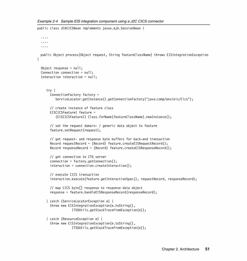
Example 2-4 Sample EIS integration component using a J2C CICS connector
public class JCACICSBean implements javax.ejb.SessionBean {
.... .... ....
public Object process(Object request, String featureClassName) throws EISIntegrationException {
Object response = null; Connection connection = null; Interaction interaction = null;
try { ConnectionFactory factory = ServiceLocator.getInstance().getConnectionFactory("java:comp/env/eis/Cics");
// create instance of feature class EISCICSFeatureI feature = (EISCICSFeatureI) Class.forName(featureClassName).newInstance();
// set the request domain- / generic data object to feature feature.setRequest(request);
// get request- and response byte buffers for back-end transaction Record requestRecord = (Record) feature.createEISRequestRecord(); Record responseRecord = (Record) feature.createEISResponseRecord();
// get connection to CTG server connection = factory.getConnection(); interaction = connection.createInteraction();
// execute CICS transaction interaction.execute(feature.getInteractionSpec(), requestRecord, responseRecord);
// map CICS byte[] response to response data object response = feature.handleEISResponseRecord(responseRecord);
} catch (ServiceLocatorException e) { throw new EISIntegrationException(e.toString(), ITSOUtils.getStackTraceFromException(e));
} catch (ResourceException e) { throw new EISIntegrationException(e.toString(), ITSOUtils.getStackTraceFromException(e));
Chapter 2. Architecture 51
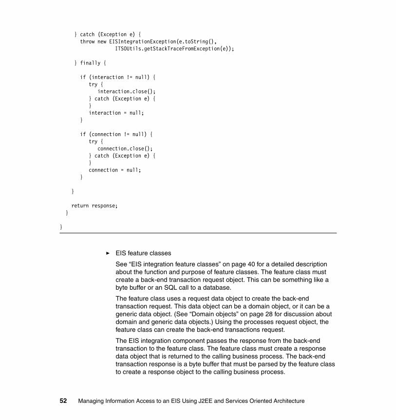
} catch (Exception e) { throw new EISIntegrationException(e.toString(), ITSOUtils.getStackTraceFromException(e));
} finally {
if (interaction != null) { try { interaction.close(); } catch (Exception e) { } interaction = null; }
if (connection != null) { try { connection.close(); } catch (Exception e) { } connection = null; }
}
return response; }
}
� EIS feature classes
See “EIS integration feature classes” on page 40 for a detailed description about the function and purpose of feature classes. The feature class must create a back-end transaction request object. This can be something like a byte buffer or an SQL call to a database.
The feature class uses a request data object to create the back-end transaction request. This data object can be a domain object, or it can be a generic data object. (See “Domain objects” on page 28 for discussion about domain and generic data objects.) Using the processes request object, the feature class can create the back-end transactions request.
The EIS integration component passes the response from the back-end transaction to the feature class. The feature class must create a response data object that is returned to the calling business process. The back-end transaction response is a byte buffer that must be parsed by the feature class to create a response object to the calling business process.
52 Managing Information Access to an EIS Using J2EE and Services Oriented Architecture

� J2C connectors
Used by the EIS integration components for connections to a back-end system, for example to CICS / COBOL or IMS. Refer to the IBM Redbook Patterns: Self-Service Application Solutions Using WebSphere for z/OS V5, SG24-7092, or WebSphere for z/OS V5 Connectivity Handbook , SG24-7064, for details about J2C and CICS / IMS connectors.
� JDBC DataSource
This EIS integration component uses a javax.sql.DataSource for its connection pooling to a database. A java.sql.Connection is used for the connection to the database.
A JDBC integration component delegates processing to a feature class by passing a java.sql.Connection object to the feature. Using the java.sql.Connection object, the feature can integrate with the database performing SQL transactions using java.sql.Statement, java.sql.PreparedStatement and java.sql.CallableStatement (for stored procedures) objects.
Tip: Use WebSphere Studio Application Developer Integration Edition tools to create format beans and format handlers from you C structures or copybooks. Your feature classes can then use these helper classes to create a byte buffer for a back-end transaction request and to parse a byte buffer from a back-end transaction response into a bean.
Chapter 2. Architecture 53

Behavioral viewFigure 2-11 illustrates the behavioral view of the logical architecture.
Figure 2-11 EIS integration logical architecture behavioral view
Figure 2-11 illustrates the logical EIS system process with its main activities. A real-world production EIS system process will have more activities. The following sections discuss some of the main activities of the EIS system process.
ConfigurationThe configuration activity (or activities) must use the supplied business process context (a context name, a context ID, and so on) to get the input parameter values of the EIS component, as well as to determine if the EIS component is local or remote to the EIS system process.
Example 2-5 on page 55 is a sample EIS system process configuration. This sample shows some of the elements and attributes that you can define for your business processes. See “Versioning” on page 23 for a discussion about versioning in context to a back-end system integration architecture.
EIS Service Endpoint
context-id + request-business-object
Request Handling
Cache
Security
Response HandlingResponse-business-object
or
EIS-service-fault
Interaction Layer
Processing Layer
Map EIScomponent-responsestart validate Config-file Local/remote end
Map EIScomponent-request
Invoke remoteEIS component
Map EIScomponent-request
Configuration errorEIS component errorRemote EIS adapter errorGeneral/Catch-All error
EIS System Process
Busi
ness
Del
egat
e
JMSTCP/IPWeb Service
SOAP/HTTPSOAP/JMS
Adap
ter
EIS
Invoke localEIS component
EIS
EIS system process exception handler
54 Managing Information Access to an EIS Using J2EE and Services Oriented Architecture

Example 2-5 Sample EIS system process configuration
<eis-integration> <context businessprocess="StockTrading/debit-account"> <eis location="local"> <integration style="JCA-IMS" feature="com.itso.trader.feature.ims.DebitAccount"/> </eis> </context> <context businessprocess="StockTrading/reserve-stock"> <eis location="remote"> <integration style="JCA-CICS" feature="com.itso.trader.feature.cics.ReserveStock"/> <proxy class-name="com.itso.trader.RemoteEISProxy" method="process"/> </eis> </context> <context businessprocess="account-enquiry"> <eis location="local"> <integration style="JCA-CICS" version="1" feature="com.itso.trader.feature.cics.BuyStock"/> <integration style="JCA-CICS" version="2" feature="com.itso.trader.feature.cics.version2.BuyStock"/> </eis> </context> <context businessprocess="RecordAudit"> <eis location="local"> <integration style="JDBC" version="1" feature="com.itso.trader.feature.jdbc.AuditEntry"/> <integration style="JCA-IMS" version="2" feature="com.itso.trader.feature.ims.AuditEntry"/> </eis> </context></eis-integration>
MappingThe EIS system process must map its process variable(s) into the EIS component variable. The EIS system process must map the request to the EIS component, and the response from the EIS component into its own process variable(s). It must map:
� The request domain or generic data object for the EIS component request
The EIS feature uses the request object to create a EIS request byte buffer or JDBC SQL Statement.
Chapter 2. Architecture 55
� Configuration values
EIS component uses the configuration values to handle the back-end system integration. See “EIS component” on page 49 for a discussion about the EIS component.
� The EIS response data object into its process variable(s)
Invoke EIS componentInvoke a local or a remote EIS component, using either a local EIS component partner link, or the remote EIS component proxy. See Table 2-9 on page 39 for discussion about local versus remote EIS components.
Exception handlerThe EIS system process must handle any system or application type errors. Possible system and applications errors that must be handled are:
� EIS system process exceptions
– Bugs in the system process– Developer bugs that can cause a NullPointerException in Java snippets– Mapping requests or responses
� Configuration activity errors
– Bad or invalid business process context values– No configuration sources– Parsing errors on the configuration sources
� EIS component errors
– Any local component exceptions– Any remote component exceptions, including system errors or J2C
connector errors
� A general / Catch-All
56 Managing Information Access to an EIS Using J2EE and Services Oriented Architecture

Figure 2-12 shows a detailed view of EIS components with their relationships.
Figure 2-12 EIS component model
EIS component adapter(s)Figure 2-11 on page 54 indicates that the invoke remote activity calls the remote EIS component via an adapter. Exposing your remote EIS component using a JMS adapter allows you to have assured delivery of your messages, even in cases of system outages. See Chapter 6, “EIS integration using Java Message Service” on page 121 for a detailed discussion about using JMS and Message Orientated Middleware (MOM) in your EIS integration architecture.
Another benefit that you might want to consider when using JMS is that you can control the time-out value between sending to your remote EIS component and receiving a response. You can specify a time-out when you receive data from a JMS response queue. You might want to consider this when integrating with a remote or external EIS where you have potential latency in the network. Given the context of your use case and the SLA you have with your business, using a JMS adapter in front of your EIS component allows you to explore architecture, design, and even different patterns for your EIS integration solution.
Chapter 2. Architecture 57
2.3 Key technologiesThe architecture discussion up to now has focussed mainly on architectural issues, patterns, components, services, and processes for creating an EIS integration architecture.
Of course, any architecture that you create must have a detailed design and must be implementable. Otherwise, what would be the purpose of creating an architecture that cannot be implemented?
Some of the discussions in the architecture chapter have mentioned technologies or specifications, most notably J2C and JMS. You would also have noticed the architecture chapter suggesting a services-based style of architecture, commonly referred to as SOA. Of course, SOA is not an implementation architecture but rather a style of architecture.
You can assert that calling CICS / COBOL routines on your EIS from your desktop C/C++ application is a services-based architecture. The fact that you could have used proprietary technologies, such SNA / APPC, and your own proprietary protocol does not suggest that you do not have a services-based architecture. Your services (in this example scenario, your CICS / COBOL routines) might not pass an interoperability test. However, that is another discussion and technical challenge.
Our architecture discussion mentions a lot of catchy phrases used by software architects like interoperability, components, loose coupling, adaptability, scalable flexible on demand solutions, services, and so on. The following sections discuss some of the key technologies that you can use to implement this architecture.
J2EEJava 2 Platform, Enterprise Edition (J2EE) is a set of coordinated specifications and practices that together enable the development, deployment, and management of multi-tier, server-centric applications. J2EE builds on top of the Java 2 Platform, Standard Edition (J2SE) platform with additional capabilities that are necessary to provide a complete, stable, and secure environment for an enterprise level application.
The J2EE platform provides a reusable component model, using a suite of technologies, such as Enterprise JavaBeans, JavaServer Pages (JSP), Java Servlets and so on, to allow application developers to build and deploy multi-tier J2EE applications that are platform and vendor-independent. The J2EE platform shares the "Write Once, Run Anywhere" approach of the Java platform and has gained significant industry support.
58 Managing Information Access to an EIS Using J2EE and Services Oriented Architecture
More information of J2EE can be found at:
http://java.sun.com/j2ee/index.jsp
Web servicesThe W3C Web Services Architecture Working Group has provided the following definition for Web services:
A Web service is a software application identified by a URI, whose interfaces and bindings are capable of being defined, described, and discovered as XML artifacts. A Web service supports direct interactions with other software agents using XML-based messages exchanged via Internet-based protocols.
The primary technologies that make up Web services consist of:
� Extensible Markup Language (XML)
A specification developed by W3C that provides a generic language for describing content in a structured way to facilitate data interchange between computer applications.
� SOAP
A XML-based protocol that is used to facilitate exchange of information in a decentralized, distributed environment. It is used in combination with a variety of other standard Internet technologies such as SMTP, HTTP, and FTP.
� Web Service Description Language (WSDL)
A XML-based language that provides a standardized way of describing the interface of a Web service.
� Universal Description, Discovery, and Integration (UDDI)
A worldwide registry of Web services to facilitate advertisement, discovery and integration.
The following is a list of key characteristics of Web services:
� Web services are language independent and interoperable.
The core technologies of Web services, such as XML, SOAP, WSDL, and UDDI , are built using open source projects, promoting vendor independence and interoperability. In addition, the use of technologies allows the service provider and service requester to communicate without knowing the platforms and languages that the other is using. This language and platform independence in turn facilitates interoperability.
� Web services are loosely coupled
Traditionally, application design depended on tight interconnections at both ends. In Web services, a consumer of a Web service is not tied to the service provider directly. Instead, the service provider can change its interface over
Chapter 2. Architecture 59

time without compromising the consumer’s ability to interact with the service. This results in a loosely coupled system, allowing a more flexible re-configuration for an integration of the services in question as well as ease of maintaining software systems.
� Web services are composable.
Simple Web services can be aggregated to form complex Web services either through workflow techniques or by invoking lower-layer Web services from a Web service implementation. This composition is made possible and easier because Web services are modular, coarse-grained units.
BPEL4WSBPEL4WS is the notation for Business Process Execution Language for Web Services (BPEL4WS). It was first specified in July 2002 by BEA, IBM, Microsoft®, SAP, and Siebel to combine XLANG and WSFL, approaches that were described previously by Microsoft and IBM respectively. BPEL4WS aims to provide a language that formally specifies business processes that are based on Web services, thus extending the Web services interaction model to support business processes.
At the time of this writing, the latest release of the specification is version 1.1, which was submitted to the OASIS standards group in May 2003. A copy of the standard is available at:
http://www.ibm.com/developerworks/webservices/library/ws-bpel/
Support for BPEL4WS at the time of this writing is emerging in some products and technology previews. IBM provides BPWS4J as a runtime engine for WebSphere Application Server and Apache Tomcat. The BPWS4J toolkit also includes a development tool which can be downloaded from:
http://www.alphaworks.ibm.com/tech/bpws4j
JCAJ2EE Connector Architecture (JCA) is part of the J2EE 1.3 specification. It defines an open, portable standard that allows J2EE applications to access resources in diverse, heterogeneous EIS systems. These EIS systems include Enterprise Resource Planning (ERP), mainframe transaction processing systems (such as IBM CICS), non-relational databases, and legacy applications. JCA achieves this portability by providing a set of Java interfaces that are scalable and secure and that provide transactional support.
From the EIS vendors’ perspective, the JCA specification allows an EIS vendor to provide a standard resource adapter for its EIS. This resource adapter plugs into an J2EE application server to provide connectivity between the J2EE application running on the application server and the target EIS systems. So, a
60 Managing Information Access to an EIS Using J2EE and Services Oriented Architecture
JCA-compliant application vendor is assured of seamless connectivity to multiple systems.
WebSphere Business Integration AdaptersWebSphere Business Integration Adapters facilitate application integration to different legacy applications, technologies, and mainframe systems through one consistent approach. These adapters allow heterogeneous business applications to exchange data over an integration broker such as WebSphere Business Integration Message Broker or WebSphere Business Integration Server Foundation.
The WebSphere Business Integration Adapters are built using a common adapter framework and generally have the following characteristics:
� Bi-directional� Configurable through metadata� Reusable infrastructure component� Supports multi-threaded business object processing
You can find more information about these characteristics in the IBM redbook, Patterns: Implementing an SOA Using An Enterprise Service Bus, SG24-6346. For a complete and current list of WebSphere® Business Integration Adapters, see:
http://www.ibm.com/software/integration/wbiadapters
JMSMessaging oriented middleware (MOM) is a popular choice for integrating applications with existing enterprise information systems. So, MOM vendors provide application developers with APIs to perform this integration. These APIs are vendor specific and hence are proprietary. However, while a MOM vendor may use proprietary message formats and implements its own networking protocols to exchange messages, the basic semantics of the developer APIs provided by different MOMs are the same. This similarity in APIs makes the JMS possible.
JMS is an API for enterprise messaging created by Sun Microsystems. The purpose is to provide a standard, open and portable way for Java based applications to access messaging middleware. The use of JMS in EIS integration is described in a later section.
Business Process ContainerThe Business Process Container, also known as the Business Process Choreographer, is a business-process engine in WebSphere Business Integration Server Foundation. It is used to choreograph all kinds of business
Chapter 2. Architecture 61

processes and provides efficient execution of both short-running and long-running processes.
The business processes that are implemented in an enterprise typically require a mixture of human and IT resources. The types of business processes can vary greatly, ranging from Web services navigation to business transaction support. Business processes can be automatic, recoverable processes or processes that require human interaction. With Business Process Container, you can combine business process technology with any other service offered by the open J2EE architecture.
J2SESome of the J2EE purists will probably question why J2SE can be a possible implementation option, or indeed, why should it even be considered?
Consider for a moment a deployment environment where applications and business processes execute at a remote branch or retail site to cater for offline scenarios. Typically, in these kinds of deployment architectures, you find that the presentation, application, process, and component layers are deployed to every site. (See Table 2-1 on page 14 for architecture layer descriptions.)
Depending on the number of remote sites (and of course the IT budget of your organization), you sometimes find that these type of deployment scenarios do not have a fully compliant J2EE application server processing their applications at every remote site. Sometimes, you find a lightweight application server with only a Web container to process Java Servlets or JSP, or you find only J2SE running in remote sites.
Maintaining and supporting hundreds of application server installations across a country, or even across the globe, can be very costly and difficult to maintain. Some remote sites in rural areas might have to support only one to two users, and if offline processing is important for your business, deploying full J2EE-compliant application servers to all of these sites might be very expensive, again, depending your organizations IT budget.
Plain Old Java Objects (POJOs) can be used to implement this architecture. You do not have to use a J2C connector in a managed environment, nor do you have to use an application server’s pooling services, and so on. Of course, you would probably have to develop most of the quality of services (QOS) that an application server provides to your applications yourself. You would have to develop services such as connection pooling, transaction management, security, multi-threaded access, object pooling, and so on by yourself, as well as a component and execution architecture for your application(s) executing in remote sites.
62 Managing Information Access to an EIS Using J2EE and Services Oriented Architecture

While we do recommend that you implement this architecture on J2SE, we do acknowledge that some deployment architectures that have to cater for offline processing (also sometimes referred to as disconnected processing) might not have full J2EE compliant application servers deployed to all of remote sites.
2.4 Architecture validationA bad “architecture can have the following characteristics:
� Monolithic, so even small changes are distributed through code and cause unpredictable results with long compile, link, and debug cycle times
� Hidden implicit coupling in code
� Multiple and inconsistent ways of doing the same thing
� Not documented and so has a high learning curve
What is the criteria that you should use to validate an architecture? Table 2-10 lists some suggestions by Dana Bredemyer (see http://www.bredemeyer.com).
Table 2-10 Architecture validation
Note: Edward M Tuggle, in his article Migrating to a service-oriented architecture, Part 2, discusses the Enterprise Workflow Architecture (EWA) framework. EWA is a component and execution architecture that can be used in a J2SE runtime environment. You can view this article at:
http://www-106.ibm.com/developerworks/library/ws-migratesoa2/
Architecture validation Description
Good Technically sound and clearly represented.A good architecture solves the problem that it solves well, but it does not necessarily solve the right problem.
Right Meets the needs and objectives of stakeholders and the system.A right architecture is one that enables the development organization to implement the current business strategy and to evolve to keep pace with changes in business strategy.
Successful The architecture was actually used in designing and developing the system.
Chapter 2. Architecture 63

64 Managing Information Access to an EIS Using J2EE and Services Oriented Architecture

Chapter 3. Scenario overview and design
This chapter discusses the scenario that we chose to better explain and illustrate how to implement a service oriented architecture (SOA) using J2EE. It gives a description of the scenario and explains the business and technology requirements for the scenario. This chapter also illustrates the technical design and system architecture and explains the interaction between systems and their services.
3
© Copyright IBM Corp. 2005. All rights reserved. 65

3.1 Scenario description and requirementsThis scenario involves the ITSO Trading Firm, which provide customers with the service to buy and sell stocks.
A customer at an internet trading site creates a request to buy a number of shares at a target price. The system processes the order by validating the order. Then, the system retrieves the current stock analysis information and performs a risk analysis using the customer’s profile. The system debits the users account for the amount required, then places a request with the brokerage system for the number of shares desired. If successful, the customer is sent an e-mail notification. If the purchase request fails, the customer’s account is then credited, and a notification of the failure is sent via e-mail.
3.1.1 Business descriptionITSO Trading Firm allows customers to login to the trading Web site and perform queries on company stocks and purchases and to sell shares of stocks.
A customer can place an order with the system, which retrieves a quote to withdraw money to purchase the stock, then place an order with the broker. Figure 3-1 shows the business view for this scenario.
Figure 3-1 ITSO Trading Firm business
The Internet Trading System from ITSO Trading Firm provides customers the option to link to their checking account to provide funds for the stocks they buy and sell. The firm uses the stock quote service from ITSO FastQuote Incorporated which updates the firm’s quote data store periodically. The
UserPlaces Order
ITSO Trading Firm
Buy and SellShares
TradeService
StockAnalysisService
Stock Broker
66 Managing Information Access to an EIS Using J2EE and Services Oriented Architecture

information that is updated includes stock price and analysis information. The firm also uses the ITSO Trading Firm Stock Brokerage System to acquire the shares of stocks for their customers. The firm allows customers to place conditions on orders when buying and selling shares. These conditions include:
� The ability to place a future order based on a target stock price.� The ability to place a time based restriction on an order.� The ability to place an order based on company stock analysis.
The firm provides e-mail notification to customers on the outcome of their orders.
The firm uses stock and customer information to make trading decisions based on business rules and policies. The stock quote service provides analysis information that is used when applying policies on an order. The trading services allows for risk based investments using the customers risk profile and the stock performance analysis data.
ITSO Trading Firm plans in the near future to replace the periodic data repository system which holds stock information with an SAP system. This system change needs to be considered in the design of the solution.
3.1.2 Business use casesThis use case covers the basic flow to be completed for this scenario. The Buy Shares use case shows the associations between different systems as seen by the business. Figure 3-2 displays the use case for when a customer issues a request to buy shares through the Internet Trading System.
Figure 3-2 Customer Buy Shares use case
Chapter 3. Scenario overview and design 67

A trader or customer issues a request with the Internet Trading System to purchase a number of shares of a certain stock. The Internet Trading System validates the stock with the Trader Application. Then, it proceeds to retrieve stock analysis and match it against the customer’s profile. An order to buy the stock is then issued with the brokerage system. Not shown in this use case is the notification for a successful order request via e-mail. The place buy order request is a composite use case which involves several other use cases which are described later in this chapter, showing how the trading and brokerage system are used.
Figure 3-3 illustrates the use case for the place order activity within the buy shares scenario.
Figure 3-3 Place Order use case
The trading system debits the customer’s account and submits an order request the brokerage system. The send order request is a composite use case which involves the asynchronous request for the order to the brokerage system. Figure 3-4 shows the retrieve stock use case.
Figure 3-4 Retrieve Stock Analysis use case
Internet Trading System
Bank
Brokerage System
Debit Account
Send Order Request
Stock Analysis System Analysis Retriever
Validate Request
Get Stock Analysis
Audit Request
68 Managing Information Access to an EIS Using J2EE and Services Oriented Architecture

There are other use cases that exist for the business which involve:
� The matching of customer profile to stock performance, which is an interaction within only the Internet Trading System, where the stock analysis information is checked against the customer’s profile.
� The failure to place an order with the brokerage system, and the recovery procedures that are activated. This includes the crediting of the customer’s bank account and a notification of the failure to purchase shares.
There are numerous other business use cases in this scenario that we do not cover. Many of these are related to exceptions, recovery, and extrapolating each use case where appropriate.
3.1.3 Business requirementsThe ITSO Trading Firm requires that the customer has easy-to-use, responsive, and customizable interactions with the Internet Trading System. The solution provided should be an on demand operating environment that enables the company to adapt to changes, as well as be ready for growth, scalable, and resilient.
The solution should contain components to allow different departments of the business to take advantage of the solution. These components also enable the software to be moved to different environments or even isolated if necessary. The solution must be standards-based, where a mature and robust enough standard exists. The solution should be keen in allowing for the use of proposed specifications that will soon be standards or are going through the review processes.
ITSO Trading Firm would like to use proven technology within the solution, with the capability of high volume throughput and high availability. The interaction and processes need to be secure and configurable. Security is a major requirement in this scenario, and each phase of the process needs to be secure. The firm would prefer a single sign-on solution.
The transactions by customers should be resilient. They should still be possible even if parts of an external or remote service is unavailable for a short period of time.
ITSO Trading Firm requires that the solution can support multiple stock analysis companies. They would like to be able to decide on an analysis based on a criteria to be determined and choose which company’s service that they will use.
Chapter 3. Scenario overview and design 69

Table 3-1 consists of the firm’s key business requirements and the description of some of the attributes that are required to meet the requirements.
Table 3-1 Key Requirements
3.1.4 Technology requirementsOne major requirement for ITSO Trading Firm is that the solution has a service oriented architecture (SOA), which provides the ability to link different services on demand. (For an overview of SOA components, see 2.2.3, “Components and SOA” on page 33.)
Although SOA de-couples the system to an extent, we want to emphasize that our EIS connectivity services should be available as components in the infrastructure. There should be EIS connectivity services available and easily used or plugable into different systems.
The solution should be configurable at deploy time and run time. Activities and processes should be context sensitive with the ability to execute or route processes based on the criteria found in the context data.
Because the brokerage firm is at a remote location, the solution should allow for the brokerage firm to be remote. ITSO Trading Firm will be using their in-house remote brokerage system. The solution should consider using guaranteed messaging to alleviate any time-out or synchronization issues that may arise.
There should be multiple quote and stock analysis providers for resiliency, business flexibility, and competitiveness. These features should be available as a service and be interchangeable.
Managers and analysts would like the ability to manage business processes and view reports. Services and process management should be easy and configurable. The application processes should be manageable and some monitoring should be available.
Requirement Description
Flexible Componentized and configurable
Secure Authentication and authorization, single sign-on, and encryption
Resilient High availability, redundancy, and compensation
Multiple service providers Allow for multiple quote stock analysis service providers
70 Managing Information Access to an EIS Using J2EE and Services Oriented Architecture

Security involving authentication and authorization is paramount. Encryption of the data transmitted during order requests is highly desirable. The use of single sign-on mechanism using a directory service is requested.
3.2 Logical designWe decided to use a series of business processes in a component design with layered services for the business workflow, the system processes, and the EIS components. The critical business processes represent a set of grouped services to form a logical unit of work. The system processes provide a virtual or logical enterprise service bus feature where routing, domain data transformation, and context based execution can occur.
Figure 3-5 shows the logical design of our services and the EIS systems they use for their processes.
Figure 3-5 Logical high-level services view
The Web Site Portal interacts with the firm’s Trading Services, which use other business services to complete the request. The Broker Service provides the option to buy or sell shares and uses the Broker EIS. The Trader Service provides access to the Trader Application EIS, which contains data that is related to trading stocks. The Stock Analysis Service retrieves the stock information that is required from the Stock Quote EIS.
User
Trading Firm - High-Level View
Stock QuoteEIS
TradingServices
TraderService
StockAnalysisService
Broker Service BrokerEIS
TraderAppEIS
Web Site Portal EIS Systems
Chapter 3. Scenario overview and design 71

3.2.1 High-level design viewsThis section describes the logical high-level system view showing the components and enterprise applications involved. It gives a high-level view of the processes that make up the business functionality of the system and then looks at the services that are provided in the system.
System viewWe decided to go with a component design with layered services for the business workflow, the system processes, and the EIS components. Figure 3-6 shows the logical design of our components and how they interact with each other. There is a system process that provides for context-based requests and an facade into the EIS components.
Figure 3-6 Logical high-level system components view
The Critical Business Process is where the business-centric activities occur. The Internet Trading process is the main process in the system. It coordinates the activities for the buy shares scenario. The Stock Broker process handles the task of sending a request to purchase the shares and any other business needs
Logical High-Level View
StockBroker
CBP
EISSystemProcess
SP
EISComponent
IMS
AsyncTradeIMS
InternetTrading
CBP
EISSystemProcess
SP
EISComponent
CICSTrader
AppCICS
StockAnalysis
CBP
EISSystemProcess
SP
EISComponentDatabase
StockQuote
Repository
CBP - Critical Business ProcessSP - System Process
72 Managing Information Access to an EIS Using J2EE and Services Oriented Architecture

required during the request. The Stock Analysis process validates and retrieves the stock information and decides which provider it will use.
The EIS System Process uses context information found in the request to use the appropriate EIS component, including information such as the version of the back-end system that it should use.
The EIS Component provides connectivity to the EIS system or repository.
Figure 3-7 shows the logical components and interaction mechanisms in the system.
Figure 3-7 Logical high-level interaction view
In the system, the major logical components are presentation, business processes, and services as well as the EIS connectivity services which are the back-end data sources.
The presentation layer could be developed using Struts, JSP, or JavaServer Faces. The business process and services layer are Business Process Execution Language for Web Services (BPEL) processes that are integrated with the appropriate bindings for the service calls. The EIS connectivity services logical component includes J2C resource adapters and WebSphere Business
Logical High-Level View
StockBroker
BPEL
EISSystemProcess
BPEL
EISComponent
Session Bean
JMSTradeIMS
InternetTrading
BPEL
EISSystemProcess
BPEL
EISComponent
Session BeanTrader
AppCICS
StockAnalysis
BPEL
EISSystemProcess
BPEL
EISComponent
StockQuote
Repository
EJB
EJB
SOAP
WSI-F
J2CResourceAdapter
J2CResourceAdapter
WBIAdapter
Chapter 3. Scenario overview and design 73

Integration Adapters. These components are exposed using different mechanisms which include session beans and BPEL processes.
Process viewThere are three main processes available from a logical perspective: Internet Trading, Stock Broker, and Stock Analysis processes.
The Internet Trading process is the main process that handles the business flows. It receives a request from a customer to trade shares, validates the request, and retrieves the stock analysis information. It then debits the customers account and sends a trade shares request.
The Stock Broker process receives a request, validates the request, performs the appropriate buy or sell activity, and then forwards the request to the EIS.
The Stock Analysis process retrieves the stock information and performs some auditing functionality.
You can find a business process overview that shows the overall process and inter-dependencies for this scenario in 3.2.2, “Business process scenario” on page 75. You can find a thorough and detailed explanation of the process and its implementation in Chapter 9, “Integration into business processes” on page 241.
Services viewFor information about how to design and implement this view, see 2.2.3, “Components and SOA” on page 33.
There are several services available within the system. These are logical services, mainly from a business perspective. Figure 3-8 on page 75 shows the business services that are included in the system. All of these services are represented by a BPEL process.
74 Managing Information Access to an EIS Using J2EE and Services Oriented Architecture

Figure 3-8 Buy shares processes and services view
The Trade Shares service is the main component. It uses the other services as the buy shares scenario is executed. (You can find an explanation of each service in 3.2.2, “Business process scenario” on page 75.) There are other system services that are used to expose applications or technology features. These services are described in detail in 3.4.1, “System overview” on page 83.
Some of these services are remote, local, and external to the main trading services (Trade Shares). The location and grouping of the services is described in 3.3.2, “Scenario architecture” on page 78.
3.2.2 Business process scenarioFor the business process scenario, we used WebSphere Business Integration Modeler to model the process and activities for the buy shares use case. This section provides a brief explanation of the overall process without going into the constructs of the types of activities or elements that we used to implement the features.
Figure 3-9 on page 76 shows the entire process as choreographed in WebSphere Business Integration Modeler. It shows the buy shares request that are processed, the flow it takes, and decision points.
Process and Services View
Credit
SendNotification
BuyShares
PlaceOrder
SellShares
TradeShares
RetrieveData
Validate
Get StockData
Audit
ValidateStocks
Debit
Chapter 3. Scenario overview and design 75

Figure 3-9 WebSphere Business Integration Modeler buy shares scenario process
The order is validated immediately against the Trader Application through the Trader Services. The stock information is retrieved from the analysis application. A risk calculation is then performed, and the order is accepted or rejected. If accepted, the debit of the bank account is performed, then a place order is performed asynchronously. If the order was placed successfully, a confirmation is sent to the customer. If the order request was not fulfilled, then a credit (Undo Debit Account) is executed.
The main business process, Trade Shares, uses the system processes that interacts with the EIS component that are required to provide the service requested. The EIS components are partners in the trade shares business process and are partner links in the system process.
Chapter 9, “Integration into business processes” on page 241 discusses how to create the business processes and to integrate them into a business functioning system.
76 Managing Information Access to an EIS Using J2EE and Services Oriented Architecture

3.3 Technical designThis section discusses the technology and system designs that we used to architect the scenario.
3.3.1 System architectureWe used WebSphere Business Integration Server Foundation for our application server and the Business Process Container for our BPEL business processes.
The client makes requests from a Web application through a firewall into the ITSO Trading Firm trading system. A service proxy object initiates the request with the trading systems BPEL-based critical business process.
The stock broker is an internal system. However, it is at a remote location that is also running WebSphere Business Integration Server Foundation and BPEL processes.The back-end system that provides the stock trade services is an IMS system that is running on z/OS.
The stock quote and analysis is provided by business process and is an external system. Access to the stock quote information has to go through a firewall and interact with a BPEL based business process that is running on WebSphere Business Integration Server Foundation.
Figure 3-10 on page 78 shows the view of the system and the technology that we used for the solution. There are services running in the Business Process Container in WebSphere Business Integration Server Foundation. There are J2C resource adapters running in managed mode on the application server to access external and remote systems. The system uses various transport protocols to interact with the different systems.
Chapter 3. Scenario overview and design 77

Figure 3-10 Scenario technical architecture view
3.3.2 Scenario architectureThis section discusses the scenario architecture for each part of the system and the options that exist in developing them. It illustrates the architecture and integration patterns for the Internet Trading System, Validate Stock, Stock Broker, and Stock Analysis Service.
For this scenario we plan on creating three proof points while illustrating a service-oriented architecture interaction. These points include using JMS technology to access or interact with an EIS system and using J2C to access an EIS, which is two forms. One of the J2C interactions is connecting to an IMS System, the other to a CICS system. Finally, there is a SOAP-based interaction with an EIS which leverages the WebSphere Business Integration Adapter portfolio.
WAN (Wide Area Network)
WBIAdapter
StockQuote
Repository
Validate
AdapterService
SystemProcess
RetrieveStock
Business Process Container
Stock Analysis (External)
Analysis
Business Process Container
WebSphere Business Integration Server Foundation
Internet Trading System
OrderProcess
DebitService
TradingProcess
SystemProcess
ValidateStocks JCA CICS
IMS
JMS
SystemProcess JCA
Messaging
JMS
Business Process Container
Stock Broker (REMOTE)
FFiirreewwaallll FirewallFirewall
System View
WebSphere Business Integration Server Foundation
WebSphere Business Integration Server Foundation
78 Managing Information Access to an EIS Using J2EE and Services Oriented Architecture

The sections that follow discuss the systems for the scenario and the architecture of solutions that can provide the three proof points.
Internet Trading SystemThe Internet Trading System scenario involves a BPEL process that runs on WebSphere Business Integration Server Foundation. It has sub services implemented as BPEL processes.
Figure 3-11 shows the Internet Trading System that runs in WebSphere Business Integration Server Foundation Business Process Container. The interactions for the service proxy can be a partner link or the use of a proxy object, depending on implementation.
Figure 3-11 Internet Trading System process trade shares
The main process trade shares handles the coordination and business logic for the buy shares use case scenario. It interacts with the banking service to withdraw and deposit money in the customer’s account for the transactions. It uses the validate service to validate a company stock prior to submitting the
Internet Trading System
TradeShares
Services
StockAnalysisService
Service Interface
ValidateStock
PlaceOrder
Service
BankingServices
WSDLGet Stock Info
WSDLDebitCredit
WSDLValidate
WSDLBuySell
WSDLBuySell
WebSphere Business Integration Server Foundation
Process Execution Container
CBP
ServiceProxy
Service Interface
Service Interface
Service Interface
Service Interface
CBP CBP
CBP
CBP
ServiceProxy
ServiceProxy
CBP - Critical Business Process
Chapter 3. Scenario overview and design 79
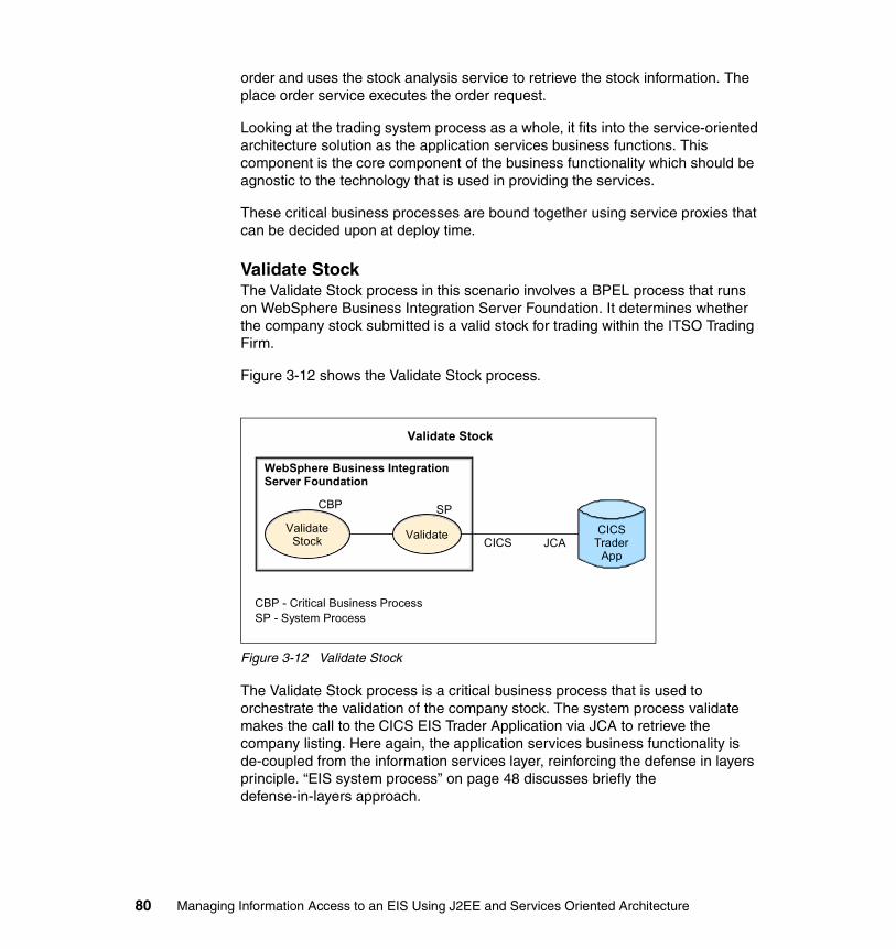
order and uses the stock analysis service to retrieve the stock information. The place order service executes the order request.
Looking at the trading system process as a whole, it fits into the service-oriented architecture solution as the application services business functions. This component is the core component of the business functionality which should be agnostic to the technology that is used in providing the services.
These critical business processes are bound together using service proxies that can be decided upon at deploy time.
Validate StockThe Validate Stock process in this scenario involves a BPEL process that runs on WebSphere Business Integration Server Foundation. It determines whether the company stock submitted is a valid stock for trading within the ITSO Trading Firm.
Figure 3-12 shows the Validate Stock process.
Figure 3-12 Validate Stock
The Validate Stock process is a critical business process that is used to orchestrate the validation of the company stock. The system process validate makes the call to the CICS EIS Trader Application via JCA to retrieve the company listing. Here again, the application services business functionality is de-coupled from the information services layer, reinforcing the defense in layers principle. “EIS system process” on page 48 discusses briefly the defense-in-layers approach.
Validate Stock
CICSTrader
App
CBP - Critical Business ProcessSP - System Process
ValidateStock
CBP
WebSphere Business Integration Server Foundation
Validate
SP
CICS JCA
80 Managing Information Access to an EIS Using J2EE and Services Oriented Architecture

Stock Broker (Place Order Service)The Stock Broker process is a logical system with a remote physical component. It consists of a BPEL process which resides in the same system as the trading system. Requests to the stock broker application are made asynchronously from the Place Order Service.
Figure 3-13 shows the Place Order Service process.
Figure 3-13 Place Order Service
The Place Order process uses the Send Order Request system process to submit an order via WebSphere MQ over JMS to the stock broker application running on a remote server over the intranet. The message is retrieved by the system process from the message store and sent to the IMS based stock broker application.
The implementation of this solution uses two WebSphere MQ JMS providers to send messages between each other. A message is placed on the local queue, then the queue manager through channels transfer the message to the remote WebSphere MQ JMS provider.
This solution could have been implemented differently by putting the message directly on the remote queue to provide for fault tolerance if the remote system is down. This setup allows the trading system to complete the transaction of the buy or sell order without disrupting the customers request during a brief failure of the external system. So, this solution provides both an asynchronous mechanism
Place Order Service
IMSJCA
IntranetWSDLBuySell
Service Interface
PlaceOrder
Service
CBP
MQJMS
(EIS)IMS
SendOrder
Request
SP
MQJMS
Provider
MQ Transport
MQJMS
Provider
SubmitOrder
SP
Remote - Stock Broker
Chapter 3. Scenario overview and design 81
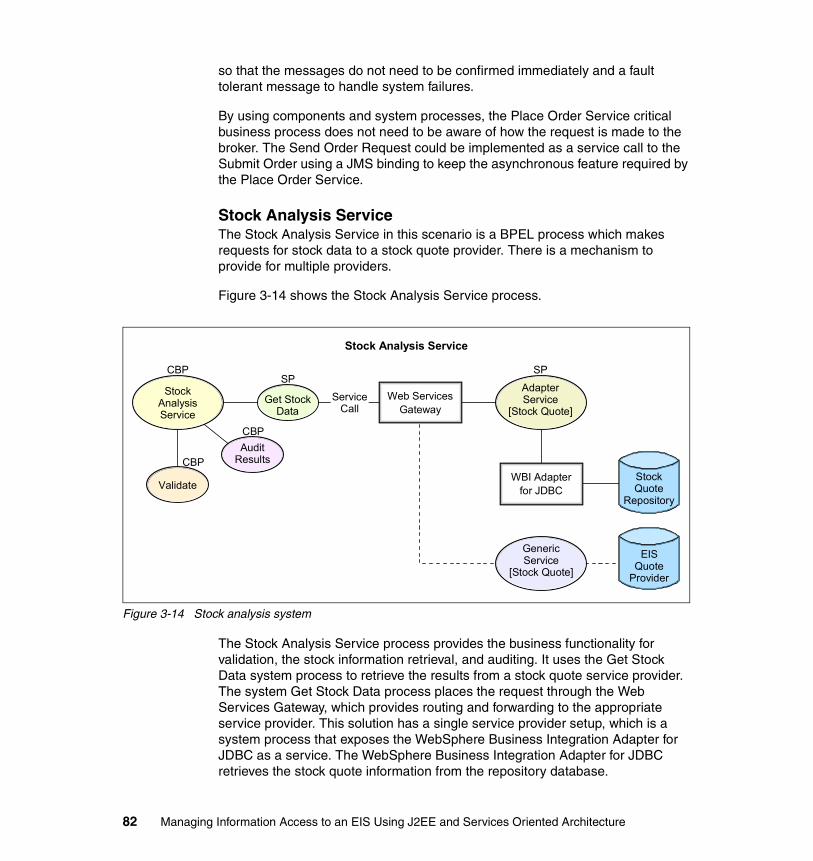
so that the messages do not need to be confirmed immediately and a fault tolerant message to handle system failures.
By using components and system processes, the Place Order Service critical business process does not need to be aware of how the request is made to the broker. The Send Order Request could be implemented as a service call to the Submit Order using a JMS binding to keep the asynchronous feature required by the Place Order Service.
Stock Analysis ServiceThe Stock Analysis Service in this scenario is a BPEL process which makes requests for stock data to a stock quote provider. There is a mechanism to provide for multiple providers.
Figure 3-14 shows the Stock Analysis Service process.
Figure 3-14 Stock analysis system
The Stock Analysis Service process provides the business functionality for validation, the stock information retrieval, and auditing. It uses the Get Stock Data system process to retrieve the results from a stock quote service provider. The system Get Stock Data process places the request through the Web Services Gateway, which provides routing and forwarding to the appropriate service provider. This solution has a single service provider setup, which is a system process that exposes the WebSphere Business Integration Adapter for JDBC as a service. The WebSphere Business Integration Adapter for JDBC retrieves the stock quote information from the repository database.
Stock Analysis Service
StockQuote
Repository
EISQuote
Provider
WBI Adapterfor JDBC
GenericService
[Stock Quote]
Validate
CBP
CBP
StockAnalysisService
AdapterService
[Stock Quote]
SP
Web ServicesGateway
ServiceCall
Get StockData
AuditResults
CBP
SP
82 Managing Information Access to an EIS Using J2EE and Services Oriented Architecture
The Web Services Gateway provides the resiliency and interchangeability that is required by the business and technology requirements mentioned in sections “Business requirements” on page 69 and “Technology requirements” on page 70.
You can find details of the features that the Web Services Gateway provides at:
http://www-106.ibm.com/developerworks/webservices/library/ws-routing/
Also, refer to the IBM Redbook Patterns: Implementing an SOA Using An Enterprise Service Bus, SG24-6346.
Now that you understand the major components of the system, we architect the scenarios so that they can be established as components, allowing for reuse and flexibility. The most important components are the logical components are the EIS connectivity services. The J2C EIS component service connects to the CICS and IMS systems, and the WebSphere Business Integration Adapter component service allows for the quick plugable reuse of various adapters.
This architecture keeps the EIS features separate from the business process functionality. In our scenario, and in the future, this architecture can be used to adapt to a changing environment and business needs.
The technology used in the proof points, JMS to JCA to SOAP, are used to achieve certain business requirements and to provide the functionality required for a service-oriented solution.
3.4 System descriptionThis section gives an overview of the systems that are involved in our scenario and their components, including where the components can be located and the role that they play in the system.
3.4.1 System overviewThis section discusses briefly the overview of the system, its components, the environment topology, and how they interact.
Chapter 3. Scenario overview and design 83

Figure 3-15 shows the overall system.
Figure 3-15 System Overview
The system that encompasses the total scenario involves two internal systems and one external system for the Buy Shares scenario.
The internal systems incorporate both the Internet Trading System and the business process for ITSO Trading Firm. These processes involve two J2EE applications that run on WebSphere Business Integration Server Foundation, one functioning as the main business process for the Internet Trading System and the other for the Stock Broker. The Stock Broker is in a remote location on the WAN.
The internal business process also communicates with a CICS system that has some trader information that the system uses to process incoming requests. This CICS system is hosted on a z/OS® operating environment.
Internet Trading System
Cluster
WebSphere Business Integration Server Foundation
Client
Web ApplicationOrder
WebSephere Business Integration Server Foundation
Stock Broker
MQ
MQ
IMSJCA
JMS
JMS
CICS
Trading Process
Trader CICSProcess
CICSJCA
z/OS System
CTG
Analysis
Stock Analysis
RepositoryEIS
EIS System
AdapterWBI
Adapter
MQ
WebSephere Business Integration Server Foundation
84 Managing Information Access to an EIS Using J2EE and Services Oriented Architecture

The external system is exposed via a Web service that retrieves stock analysis and quote information from a repository stored in a relational database. The information is retrieved from the database using the WebSphere Business Integration Adapter for JDBC. The service link between the adapter and the business process is done through JMS calls to the adapter framework. The external adapter service and stock quote service is running in an instance of the WebSphere Business Integration Server Foundation application server.
For more information about the configuration, deployment, and domain structure see Chapter 4, “Environment” on page 87 and the chapters in Part 2, “Development example” on page 93
Chapter 3. Scenario overview and design 85

86 Managing Information Access to an EIS Using J2EE and Services Oriented Architecture

Chapter 4. Environment
This chapter describes the setup of the environment that we used to implement our proof of concept. It discusses the basic infrastructure and provides an overview of the back-end subsystem of our environment.
4
© Copyright IBM Corp. 2005. All rights reserved. 87

4.1 Development environmentTo develop our proof of concept, we used the following products:
� WebSphere Studio Application Developer Integration Edition Version 5.1.1. It supports the development of BPEL processes and JCA services.
� WebSphere Business Integration System Manager Version 4.2.2. It supports the development of WebSphere Business Integration Adapter services.
� WebSphere Business Integration Modeler Version 5.1. It is the business analyst tool to model the high-level process.
� Rational® XDE™ 2003 to support the requirement analysis and the design phases.
4.2 CICS system and connectorsThe Internet Trading system is composed of two nodes, the business integration node and the back-end node, as shown in Figure 4-1. The EIS is a CICS Transaction Server for z/OS Version 2.2.
The CICS Transaction Gateway is a set of client and server software components that incorporate the facilities of the CICS Universal Client, which allow a Java application to invoke services in a CICS region.
Figure 4-1 Software components of the Internet Trading system
The back-end node is a z/OS system where the following products are installed:
� CICS Version 2.2� CICS Transaction Gateway Version 5.1
88 Managing Information Access to an EIS Using J2EE and Services Oriented Architecture

The business integration node is a Windows® 2000 system where the following products are installed:
� WebSphere Business Integration Server Foundation Version 5.1.1
� The JCA Resource Adapter that comes with CICS Transaction Gateway Version 5.1
� WebSphere MQ Version 5.3 with the CSD 07
4.3 IMS system and connectorsThe Stock Broker system is composed by two nodes, the business integration node and the back-end node, as shown in Figure 4-2. The EIS is IMS Version 8 for z/OS.
IMS Connect is a TCP/IP server that enables TCP/IP clients to exchange messages with IMS Open Transaction Manager Access (OTMA). This server provides communication links between TCP/IP clients and IMS (data stores). It supports multiple TCP/IP clients that access multiple datastore resources. To protect information that is transferred through TCP/IP, IMS Connect provides Secure Sockets Layer (SSL) support to protect and secure the information. IMS Connector for Java is the JCA-compliant resource adapter, and it is a component of IMS Connect.
Figure 4-2 Software components of Stock Broker
The back-end node is a z/OS system where the following products are installed:
� IMS Version 8� IMS Connect Version 2.1 with PTF UQ82140
Chapter 4. Environment 89
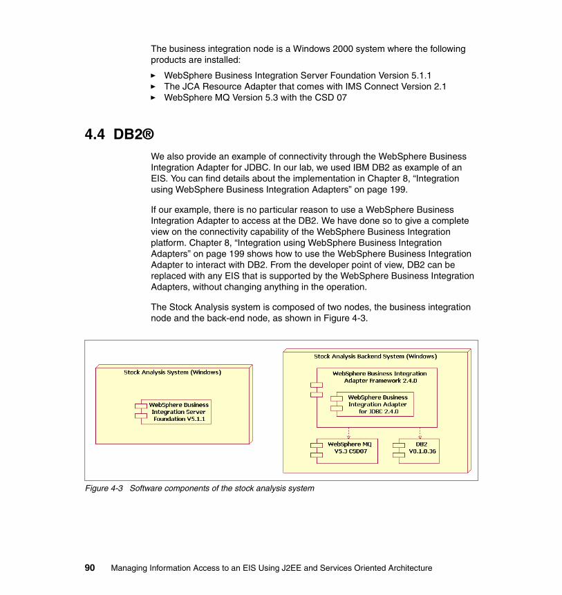
The business integration node is a Windows 2000 system where the following products are installed:
� WebSphere Business Integration Server Foundation Version 5.1.1� The JCA Resource Adapter that comes with IMS Connect Version 2.1� WebSphere MQ Version 5.3 with the CSD 07
4.4 DB2®We also provide an example of connectivity through the WebSphere Business Integration Adapter for JDBC. In our lab, we used IBM DB2 as example of an EIS. You can find details about the implementation in Chapter 8, “Integration using WebSphere Business Integration Adapters” on page 199.
If our example, there is no particular reason to use a WebSphere Business Integration Adapter to access at the DB2. We have done so to give a complete view on the connectivity capability of the WebSphere Business Integration platform. Chapter 8, “Integration using WebSphere Business Integration Adapters” on page 199 shows how to use the WebSphere Business Integration Adapter to interact with DB2. From the developer point of view, DB2 can be replaced with any EIS that is supported by the WebSphere Business Integration Adapters, without changing anything in the operation.
The Stock Analysis system is composed of two nodes, the business integration node and the back-end node, as shown in Figure 4-3.
Figure 4-3 Software components of the stock analysis system
90 Managing Information Access to an EIS Using J2EE and Services Oriented Architecture

The back-end node is a Windows 2000 system where the following products are installed:
� DB2 Version 8.1� WebSphere MQ Version 5.3 with the CSD 07� WebSphere Business Integration Adapter Framework 2.4.0� WebSphere Business Integration Adapter for JDBC 2.4.0
The business integration node is a Windows 2000 system where WebSphere Business Integration Server Foundation Version 5.1.1 is installed.
4.5 DeploymentThere are no particular cautions or special steps that are needed for the software installation and configuration of the systems in our sample.
To get an assured delivery between the Internet Trading System and Stock Broker, we set up a WebSphere MQ channel between the queue manager on those systems.
You can find more details about the z/OS system in the IBM Redbook WebSphere for z/OS V5 Connectivity Handbook, SG24-7064. Our sample used the same z/OS environment as that redbook.
Chapter 4. Environment 91

92 Managing Information Access to an EIS Using J2EE and Services Oriented Architecture
Part 2 Development example
This part describes the development of key functions that are part of the EIS integration sample that we used in this redbook.
Part 2
© Copyright IBM Corp. 2005. All rights reserved. 93

94 Managing Information Access to an EIS Using J2EE and Services Oriented Architecture

Chapter 5. Using J2EE Connector Architecture
This chapter gives an overview of the J2EE Connector Architecture. It explains how a J2C Resource Adapter can participate in EIS integration scenarios. This chapter also describes how to use a J2C resource adapter for the CICS in our scenario. It explains what quality of service can be associated with using this solution and how to implement it.
5
© Copyright IBM Corp. 2005. All rights reserved. 95

5.1 J2EE Connector Architecture overviewThe J2EE Connector Architecture (JCA) defines a set of standards about how a resource adapter provides connectivity to an EIS and how the system contracts with an application server.
The set of contracts between the resource adapter and the application server provides services to the resource adapter and maintains a plugable mechanism when running in the application server.
There are currently two versions of the JCA specification. The JCA 1.0 specification only includes outbound communication and does not include life cycle management and work management. The JCA 1.5 specification includes inbound communication and the following system contracts:
� Transaction management
Involves the coordination of the application servers transaction manager and the EIS transaction resource managers to provide transactional functionality through the resource adapter.
� Connection management
Involves connection pooling and the framework for creating and managing physical connections to the EIS.
� Life cycle management
Involves the start up and shut down functions of the resource adapter, and provides timely and consistent contracts for these procedures.
� Work management
Allows the resource adapter to schedule and submit work tasks with the application server. These work tasks can facilitate processes that involve monitoring tasks.
� Security
Provides the resource adapter with features to enable security using application server mechanisms.
Components that want to access information from the EIS can do so in two ways. They can use the Common Client Interface (CCI) to make requests on the EIS, which is referred to as an outbound communication. The component can also allow the EIS to make inbound calls that send information from the EIS to the component.
The CCI provides an API that the resource adapter can implement and extend, which allows for clients to make remote function calls on the EIS. A client component gets a connection to the EIS using a connection factory.
96 Managing Information Access to an EIS Using J2EE and Services Oriented Architecture

The client uses an interaction to execute functions on the EIS. The interaction modes involves how the request is handled by the resource adapter and is specified on the InteractionSpec by stating one of the following:
� SYNC_SEND
The execution only sends an input to the EIS via the resource adapter. No output is expected.
� SYNC_RECEIVE
The execution receives a synchronous output record from the EIS.
� SYNC_SEND_RECEIVE
The execution sends an input to the EIS, and a synchronous output record is expected.
The EIS can also make calls into the application component using Enterprise JavaBeans (EJB) that are deployed on the application server. Inbound communication is only available when the adapter is running in a J2EE application server.
5.2 EIS integration using J2CThis section describes how to use a J2C resource adapter in various integration schemes. EIS-based integration typically involves a J2C resource adapter that is running in managed mode to take advantage of the application servers quality of service functionality.
As mentioned earlier, a resource adapter can expose its outbound functionality through CCI. This functionality can directly interact with the EIS. The EIS connectivity framework provides a facade into the EIS via the resource adapter, which provides de-coupling between the service provided by the J2C resource adapter and application services.
The JCA 1.5 specification stipulates how inbound communication can be accomplished using EJB. EJB enables the EIS to make calls to the application component when events occur in the EIS system.
5.2.1 J2C outbound integration patternThe outbound integration pattern involves an application component that is running on an application server or stand-alone Java application, which executes requests on the J2C resource adapter that interacts with the EIS.
Chapter 5. Using J2EE Connector Architecture 97

There are two basic patterns when running on an application server, one involves straight calls and the other involves exposing the resource adapter as a service.
Common Client Interface invocationThe patterns when interacting from within an application server use an EJB to make calls on the resource adapter through CCI calls. The EJB can then be exposed as an Enterprise Application Integration framework within the managed application space, or it can used directly. Developing a framework gains flexibility and potentially eases integration with other parts of the application.
Example 5-1 is shows the sample code which makes a call on a resource adapter.
Example 5-1 Sample CCI call to an EIS
ConnectionFactory cicsFactory =ServiceLocator.getConnectionFactory(“eis/CICS”);Connection conn = cicsFactory.getConnection();InteractionSpec spec = new ECIInteractionSpec();spec.setCommareaLength(commAreaLength);spec.setTPName(“TRDR”);spec.setFunctionName(“TRADERBL”);Interaction interaction = conn.createInteraction(spec);interaction.execute(spec,requestRecord, responseRecord);
Enterprise Application Integration frameworkThe Enterprise Application Integration (EAI) framework is the implementation of a system process of the EIS component model that is described in the following sections:
� 2.2.2, “Architecture options” on page 30� 2.2.5, “Conceptual architecture” on page 37� 7 2.2.6, “Logical architecture” on page 47
The EIS system process uses a session bean implementation. The EIS features are a Java implementation of existing functions in the EIS.
The EAI framework interacts with the EIS through the resource adapter and is exposed as features that the session bean uses. This interaction creates flexibility and de-coupling of the EIS features that are used when integrating. It allows for the quick reuse of existing features (for example, GetCompanyList that is used to retrieve a list of companies in the system). The EAI framework gives developers an clearly defined infrastructure on how they should add new features and extend the EIS access.
98 Managing Information Access to an EIS Using J2EE and Services Oriented Architecture

Service invocationThe resource adapter exposed as a service can be used in several different ways. It can be used within the Business Process Container as a partner link. It can also be used in conjunction with the Web Services Gateway, providing for some routing and flexibility.
When the resource adapter is exposed as a service within the Business Process Container, the clients make use of the Web Service Invocation Framework (WSIF) to make requests using the binding type that was specified when the service was deployed.
WSIF provides an abstract model that invokes Web services through a set of APIs regardless of how the service is implemented and where it can be found.
WSIF is composed of these features:
� An API, which provides binding independent access of a Web service through the use of an abstract model of the service.
� WSIF providers, which implement support for different transports and encodings through the use of the dynamic port factory.
� Utilities such format handlers, which support the functionality that is provided by the WSIF providers and the API.
There are several binding types, including EJB, JMS, SOAP, and J2C. The WSIF J2C binding extension provides for an easy mapping of ports, operations, and messages to the resource adapters connection, interaction, and records. The connector bindings extension allows the resource adapter WSDL to specify the InteractionSpec values in a way that is understandable. A format binding specifies what message style and encodings are used, when mapping the data to its native format. For example, IBM CICS Resource Adapter, which uses COBOL copybook, has an encoding value of ibmcobol.
The client looks up the port, where the resource adapter service is located and uses the WSIFPort to create an operation that specifies the operation name as well as input and output message types. It then creates an input object and sets the parts of the message. Finally, the client executes the operation.
After the adapter service is created using the WSIF J2C binding extension, it can then be wrapped into a service using one of the following bindings for easy access within the application server.
� EJB binding
Exposes the functionality as a EJB call into the resource adapter service.
Chapter 5. Using J2EE Connector Architecture 99

� JMS binding
Uses a simulated synchronous JMS system to send messages to the resource adapter’s service.
When the resource adapter is exposed as a service, a client can use the IBM Web Services Gateway to make requests on the resource adapter.
IBM Web Services Gateway overviewThe IBM Web Services Gateway is a runtime infrastructure component that serves as a SOAP processing engine that provides configurable mappings between Web service providers and requesters. Services defined with WSDL can be routed to available transport channels and ultimately the target service. The gateway components are:
� Channels that define the entry-points into the gateway and carry the Web service request and response through the gateway.
� Filters that are used to intercept service invocations which come into the gateway and act upon the services.
� Services that are described with the help of a Web Services Description Language (WSDL) document.
� UDDI references to manage the publishing of an exposed Web service to a private or public UDDI registry.
The Web Services Gateway provides the following functionality:
1. Routes messages to the target destination.
2. Provides processing for custom header tags.
3. Provides for message level security using WS-Security.
4. Provides for changes to the incoming protocol with a different outgoing protocol (SOAP-HTTP to SOAP-JMS).
When the resource adapter service is exposed through the IBM Web Services Gateway there is a mapping from the requestor to the provider using channels. The resource adapters then make a call to the EIS, returning the results through the service. This integration pattern enables the integration of the EIS through an ESB implementation.
For more information about the IBM Web Service Gateway, see:
� WebSphere Version 5.1 Application Developer 5.1.1 Web Services Handbook, SG24-6891
� Patterns: Service-Oriented Architecture and Web Services, SG24-6303
100 Managing Information Access to an EIS Using J2EE and Services Oriented Architecture
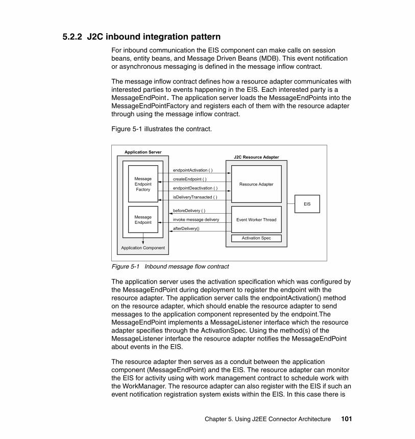
5.2.2 J2C inbound integration patternFor inbound communication the EIS component can make calls on session beans, entity beans, and Message Driven Beans (MDB). This event notification or asynchronous messaging is defined in the message inflow contract.
The message inflow contract defines how a resource adapter communicates with interested parties to events happening in the EIS. Each interested party is a MessageEndPoint. The application server loads the MessageEndPoints into the MessageEndPointFactory and registers each of them with the resource adapter through using the message inflow contract.
Figure 5-1 illustrates the contract.
Figure 5-1 Inbound message flow contract
The application server uses the activation specification which was configured by the MessageEndPoint during deployment to register the endpoint with the resource adapter. The application server calls the endpointActivation() method on the resource adapter, which should enable the resource adapter to send messages to the application component represented by the endpoint.The MessageEndPoint implements a MessageListener interface which the resource adapter specifies through the ActivationSpec. Using the method(s) of the MessageListener interface the resource adapter notifies the MessageEndPoint about events in the EIS.
The resource adapter then serves as a conduit between the application component (MessageEndPoint) and the EIS. The resource adapter can monitor the EIS for activity using with work management contract to schedule work with the WorkManager. The resource adapter can also register with the EIS if such an event notification registration system exists within the EIS. In this case there is
Application Server
createEndpoint ( )
endpointActivation ( )
endpointDeactivation ( )
isDeliveryTransacted ( )
beforeDelivery ( )
invoke message delivery
afterDelivery()
Application Component
Activation Spec
EIS
MessageEndpoint Event Worker Thread
MessageEndpointFactory
Resource Adapter
J2C Resource Adapter
Chapter 5. Using J2EE Connector Architecture 101

either a call back mechanism or some intermediate event store that is used for triggering and sending the events to the resource adapter. Finally, the message endpoint is notified of the event by a call to MessageEndPoint.
The delivery of events from the EIS can also be transacted using container managed transactions and Java Transaction API (JTA). This method of delivery uses the transaction management contract and controlling the transaction boundaries using the beforeDelivery and afterDelivery methods. These methods signify when the application server should enlist an XAResource to start and end the transaction.
For more information, see the JCA 1.5 specification at:
http://java.sun.com/j2ee/connector/download.html
5.3 The integration building block using J2CThis section describes the integration building blocks that use J2C and how the IBM CICS J2C resource adapter helps to solves the scenario problem. It describes the components of the building block and the system architecture that we used for the EIS integration.
5.3.1 Scenario problem statementMany EIS have their services and functions exposed through the use of a J2C resource adapter that is 1.0 or 1.5 compliant. Application components are more often being built to run in a J2EE application server. To manage EIS data and use existing functionality, the application components use resource adapters to interact with these enterprise systems.
For our specific scenario, the ITSO Trading Firm has an Internet Trading System J2EE application that processes trade requests made over the Web. The Internet Trading System uses a company listing to verify whether buy or sell requests can be made through the system. The information for the company list is stored in a CICS system that the firm owns.
Our Buy Shares scenario requires verification of the order against the company list. The trade shares business component of the Internet Trading System uses the list of available companies from which customers are allowed to buy shares. The component needs this process to be quick, synchronous retrieval from the CICS system. This process is facilitated by the CICS resource adapter which can be integrated into the trade shares business component as a service.
102 Managing Information Access to an EIS Using J2EE and Services Oriented Architecture

5.3.2 System architectureThe Internet Trading System is a J2EE application component which includes BPEL processes that are running in the Business Process Container, JSPs, and EJB. This scenario concentrates on the business process that is implemented using BPEL and its associated system processes.
The Internet Trading System runs in the WebSphere Business Integration Server Foundation application server space. The trading system BPEL process executes requests on the CICS system via the J2C resource adapter. The resource adapter is configured to make calls to the CICS system through the CICS Transaction Gateway that is running on a z/OS system.
The application is running on WebSphere Business Integration Server Foundation with the resource adapter. The CICS system is on a z/OS platform that is internal to the company. Figure 5-2 shows the components of the system.
Figure 5-2 System view of components
The trade shares business component makes a request on the system process requesting the company list information. The system process makes a service call on the CICS resource adapter exposed as a service. The GetCompanyList operation is invoked via a partner link in the system process, and the results are returned to the trade shares business process.
WebSphere Business Integration Server Foundation
TradingSystem
Application
CICSJCA
CICSTransaction
Gateway CICS
EIS System
Chapter 5. Using J2EE Connector Architecture 103

5.3.3 Components of the building blockThe CICS Transaction Gateway (CTG) is used to provide access to the trader CICS-COMMAREA program. The CTG is configured to connect to the CICS system, and both are running on a z/OS machine.
The trading application component runs the business processes and system functions for ITSO Trading Firm. The main component of the system is the trading system’s BPEL process that coordinates the activities during the scenario.
The IBM CICS ECI resource adapter provides connectivity to the back-end system to retrieve the company list. A system process exposes this functionality. The system process is implemented using BPEL.
5.3.4 Extending the building blockThe building block can be extended by implementing the framework integration pattern mentioned in the previous section. This extension exposes more CICS program calls via features and uses integration beans to process the requests coming from business processes.
5.4 Developing EIS interaction using J2CThe artifacts required to build this solution include:
� the IBM CICS J2C Resource Adapter which conforms to J2C 1.0 specification� the WebSphere Business Integration Server Foundation application server� the Business Process Container� the COBOL copybook, for the COMMAREA program we call� the CTG, for connecting to the CICS system.
5.4.1 The buy shares scenarioIn the Buy Shares scenario, the validation of the stock is checked against the company list. In this step, the trading system business process retrieves the list of companies from its CICS system that is running on z/OS platform. The process validates and then proceeds with the request depending on the results of the validation.
104 Managing Information Access to an EIS Using J2EE and Services Oriented Architecture
5.4.2 Creating the J2C EIS serviceThe service based on J2C EIS is the IBM CICS J2C resource adapter that is exposed as an EJB service with SOAP bindings. Here are the steps involved in creating this service using WebSphere Studio Application Developer Integration Edition:
1. Create a service project for exposing the IBM CICS Resource Adapter.2. Create a service for the COBOL program Get Company List.3. Generate EJB Deploy code with SOAP bindings.4. Test the Get Company List Service.5. Incorporate the service in the system.
Creating the service projectTo create the service project using WebSphere Studio Application Developer Integration Edition:
1. Select Windows-Preferences → J2EE. Select the radio button, Enable server targeting support.
2. Select Window → Open Perspective Business Integration.
3. Select File → New → Service Project.
4. For Project name, enter CICSJCA. Click Finish.
5. Right-click the project folder and then choose New → Package to create a package.
6. Enter com.itso.cicsjca as the package name. Click Finish.
Importing CICS resource adapter and COBOL sourceTo import the resource adapter and the COBOL source for the Get Company List Program:
1. Right-click the package and choose Import.
2. On the Import-Select panel, select RAR File. Click Next..
3. On the Connector Import panel, Click Browse, then navigate and select the \resource adapters\ctg510\cicseci.rar file.
4. For the Connector project, enter cicseciConnector. Figure 5-3 on page 106 shows this step in the wizard.
Chapter 5. Using J2EE Connector Architecture 105

Figure 5-3 CICS ECI resource adapter import
5. Click Finish.
6. Set the Target server as Integration Server v5.1 by right-clicking the cicseciConnector project and selecting Target Server → Modify.
7. To import the COBOL source, right-click the package com.itso.cicsjca. Choose Import.
8. On the Import-Select panel, choose File system. Click Next.
106 Managing Information Access to an EIS Using J2EE and Services Oriented Architecture

9. Click Browse, and navigate to the location of the Traderbl.cpp COBOL copybook source as shown in Figure 5-4.
Figure 5-4 Import COBOL code
10.Select the traderbl.ccp file. Leave defaults, and click Finish.
Building the cicseciConnector ServiceTo build the service:
1. Select the com.itso.cicsjca package,
2. Click File → New → Service Built from.
3. On the New Service panel, choose the CICS ECI service by selecting CICS ECI. The service wizard topology diagram illustrates that you are creating the WSDL files for the CICS ECI connector, which is exposed as an EJB service.
4. Click Next until you reach the Service Bindings panel.
Chapter 5. Using J2EE Connector Architecture 107

5. For Interface file name, enter Traderbl as shown in Figure 5-5.
Figure 5-5 CICS ECI service binding
6. Click Finish to generate the service and bindings WSDL. Click Ok on Next Step Information.
7. The TraderblCICSECIBinding opens so that you can specify the binding operation.
108 Managing Information Access to an EIS Using J2EE and Services Oriented Architecture
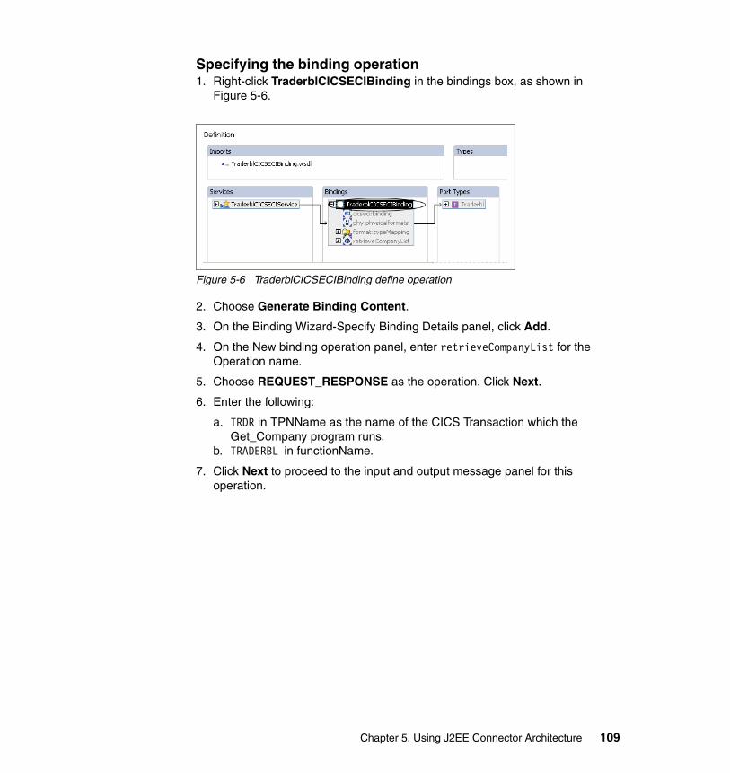
Specifying the binding operation1. Right-click TraderblCICSECIBinding in the bindings box, as shown in
Figure 5-6.
Figure 5-6 TraderblCICSECIBinding define operation
2. Choose Generate Binding Content.
3. On the Binding Wizard-Specify Binding Details panel, click Add.
4. On the New binding operation panel, enter retrieveCompanyList for the Operation name.
5. Choose REQUEST_RESPONSE as the operation. Click Next.
6. Enter the following:
a. TRDR in TPNName as the name of the CICS Transaction which the Get_Company program runs.
b. TRADERBL in functionName.
7. Click Next to proceed to the input and output message panel for this operation.
Chapter 5. Using J2EE Connector Architecture 109

8. Import the input message by clicking Import.
a. On the File Selection Page, navigate to the CICSJCA/com/itso/cicsjca/traderbl.ccp source file. Select it as shown in Figure 5-7. Click Next.
Figure 5-7 Operation -COBOL import
b. On the COBOL Import properties panel, choose z/OS for the platform. Here you specify the platform on which the CICS program is running. This changes to the defaults for the z/OS platform. Accept the changes and click Next.
110 Managing Information Access to an EIS Using J2EE and Services Oriented Architecture

Figure 5-8 Operation- COBOL import properties
c. On the COBOL Importer panel, choose COMMAREA-BUFFER.
d. For the XSD type name, enter TraderblCommare as shown in Figure 5-9 on page 112.
Chapter 5. Using J2EE Connector Architecture 111

Figure 5-9 COBOL -COMMAREA Importer
e. Click Finish.
9. Select the Use the input message for output check box, and click Finish.
10.Click Finish on the Binding Wizard panel.
112 Managing Information Access to an EIS Using J2EE and Services Oriented Architecture

Figure 5-10 shows the view of the bindings, port types, and messages that are used for the retrieveCompanyList operation.
Figure 5-10 Operation retrieveCompanyList View
Generating EJB deployment codeTo generate a session bean for the TraderblCICSECIService:
1. Right-click the TraderblCICSECIService.wsdl file. Choose Enterprise Services → Generate Deploy Code.
2. Click Next to proceed to the Inbound Service Files panel.
3. Accept the defaults, and click Next to proceed to the EJB Inbound Service Files panel shown in Figure 5-11 on page 114.
Chapter 5. Using J2EE Connector Architecture 113

Figure 5-11 Trader EJB Inbound Service
4. Click Finish, accepting the defaults for the entries for EJB port, SOAP binding properties, and SOAP port.
Configuring the Traderbl EJB JNDI bindingsTo configure the connection factory JNDI bindings that will be used by the server:
1. Navigate to the J2EE Hierarchy view. Expand the CICSJCAEJB module under the EJB Modules folder. Navigate to Session Beans → TraderblService. Double-click TraderblService to open the EJB deployment descriptor for editing.
114 Managing Information Access to an EIS Using J2EE and Services Oriented Architecture
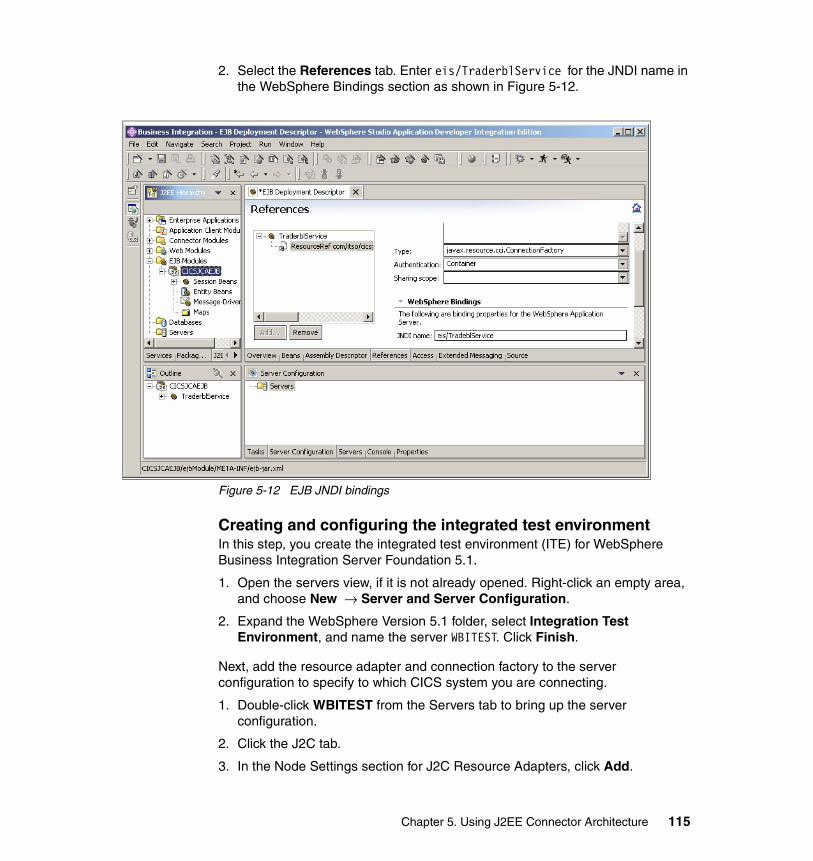
2. Select the References tab. Enter eis/TraderblService for the JNDI name in the WebSphere Bindings section as shown in Figure 5-12.
Figure 5-12 EJB JNDI bindings
Creating and configuring the integrated test environmentIn this step, you create the integrated test environment (ITE) for WebSphere Business Integration Server Foundation 5.1.
1. Open the servers view, if it is not already opened. Right-click an empty area, and choose New → Server and Server Configuration.
2. Expand the WebSphere Version 5.1 folder, select Integration Test Environment, and name the server WBITEST. Click Finish.
Next, add the resource adapter and connection factory to the server configuration to specify to which CICS system you are connecting.
1. Double-click WBITEST from the Servers tab to bring up the server configuration.
2. Click the J2C tab.
3. In the Node Settings section for J2C Resource Adapters, click Add.
Chapter 5. Using J2EE Connector Architecture 115

4. Choose cicseciConnector from the list as shown in Figure 5-13. Click OK.
Figure 5-13 Select imported CICS Resource Adapter
5. Configure the Java Authentication and Authorization Service (JAAS) authentication alias to be used by container when creating the connection factory.
a. Select the Security tab.
b. In the JAAS Authentication Entries section, click Add .
c. Enter an Alias as CISAuth. Enter the User ID and Password used to access the CICS system.
d. Click OK.
6. Configure the J2C Connection factory for the resource adapter. Click the J2C tab.
7. Select cicseciConnector from the resource adapters.
8. In the J2C Connection Factories section, click Add.
9. Enter the following:
a. Name: TraderblService
b. JNDI Name: eis/TraderblService. The same name given in the EJB deployment descriptor’s ResourceRef tab.
c. From the drop-down list for the Container-managed authentication alias, select CICSAuth.
10.Click OK.
116 Managing Information Access to an EIS Using J2EE and Services Oriented Architecture

11.Set the server and connection information.
a. Scroll down to the Resource Properties section.
b. Enter the server name of your CICS system. In our example, this name was SCSCERW.
c. Enter the ConnectionURL. In our example, this connection was tcp://wtsc52.itso.ibm.com®.
12.Press Ctl+S to save the WBITEST Server configuration.
13.Start the server by right-clicking WBITEST from the server tab and selecting Start.
5.4.3 Testing and running the scenarioYou can test the retrieval of the company list using an EJB proxy and JUnit test class.
Generating EJB proxyGenerate an EJB proxy which exposes the service through a Java class.
1. Right-click the TraderblEJBService.wsdl file. Choose Enterprise Services → Generate service proxy to launch the Generate Service Proxy wizard.
2. Choose WSIF and click Next.
3. Accept the defaults, including, class name TraderblProxy.java. Click Next.
4. Select client stub, then select the retrieveCompanyList() operation. Click Finish.
This proxy class uses WSIF to invoke the EJB retrieveCompanyList operation.
Generating JUnit test caseAdd the junit.jar to the project, then use the JUnit Test Case wizard to create the test class.
1. Change to the Java perspective. Right-click the CICSJCAEJB project, then select Properties.
2. Select Java Build Path, then the Libraries tab. Click Add External Jars.
3. Navigate to the ..eclipse\plugins\org.junit_3.8.1 folder and choose junit.jar. Click Open.
4. Click OK to add the JAR to the project’s Java Build Path.
5. Select TraderblProxy in the CICSJCAEJB project.
6. Right-click TraderblProxy then choose New → Other.
Chapter 5. Using J2EE Connector Architecture 117

7. Expand Java, then select JUnit and choose TestCase.
8. Enter TraderblProxyTest for the test case. The test class should be com.itso.cicsjca.TraderblProxy.
9. Click the check boxes for main() method, setUp(), and tearDown(). Click Next.
10.Select the retrieveCompanyList() method on the Test Methods panel.
11.Click Finish to generate the test case.
To run the test case.
1. In the test method, add the code shown in Example 5-2.
Example 5-2 Test retrieveCompanyList proxy
TraderblCommarea commarea = new TraderblCommarea();commarea.setRequest_type(“Get_Company “);//15 chars for REQUEST_TYPETraderblProxy proxy = new TraderblProxy();commarea = proxy.retrieveCompanyList(commarea);for(int i = 0; i < commarea.getCompany__name__tab().length;i++){
System.out.println(commarea.getCompany_name_tab(i));}assertTrue((commarea.getCompany_name_tab.length > 0));
2. Run the test case by right-clicking the class and selecting Run → Run As → JUnit Test. Select the test class to run. Then click Run.
The program should return the list of companies in the system and print them out to the console.
5.4.4 Creating the system processAt this stage, you have the CICS connector ready to use and the Get Company List service exposed through both a Java proxy and an EJB binding service.
To incorporate this service into the business process, you create a trader EIS business process that exposes all the trader features, including the TraderblEJBService, as a partner to the system process. You can then expose the Get Company List process through service invocations on the EIS business process. The TraderblEJBService is a partner link in the overall Trader EIS service.
The system process is explained in 2.2.6, “Logical architecture” on page 47. You can have local and remote invocations based on context information. Depending on the EIS service implementations, you can have a service or feature based interactions.
118 Managing Information Access to an EIS Using J2EE and Services Oriented Architecture
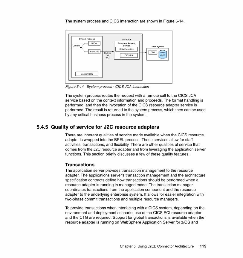
The system process and CICS interaction are shown in Figure 5-14.
Figure 5-14 System process - CICS JCA interaction
The system process routes the request with a remote call to the CICS JCA service based on the context information and proceeds. The format handling is performed, and then the invocation of the CICS resource adapter service is performed. The result is returned to the system process, which then can be used by any critical business process in the system.
5.4.5 Quality of service for J2C resource adaptersThere are inherent qualities of service made available when the CICS resource adapter is wrapped into the BPEL process. These services allow for staff activities, transactions, and flexibility. There are other qualities of service that comes from the J2C resource adapter and from leveraging the application server functions. This section briefly discusses a few of these quality features.
TransactionsThe application server provides transaction management to the resource adapter. The applications server’s transaction management and the architecture specification contracts define how transactions should be performed when a resource adapter is running in managed mode. The transaction manager coordinates transactions from the application component and the resource adapter to the underlying enterprise system. It allows for easier integration with two-phase commit transactions and multiple resource managers.
To provide transactions when interfacing with a CICS system, depending on the environment and deployment scenario, use of the CICS ECI resource adapter and the CTG are required. Support for global transactions is available when the resource adapter is running on WebSphere Application Server for z/OS and
z/OS System
CTGCICS
System Process
PartnerLink(PL)
ContextLOCAL
REMOTE
Domain Data
Resource AdapterService
Data Formatting
CICS JCA
CICS RA
Chapter 5. Using J2EE Connector Architecture 119

using a local gateway. For more information about using transactions when integrating, with CICS see:
http://ibm.com/developerworks/websphere/techjournal/0408_wakelin/0408_wakelin.html
Connection poolingThe connection management contract of the specification defines the roles of the resource adapter and application server when maintaining connections to the EIS. This connection enables the application server to provide efficient connection pooling. It allows the application server to deal with dead and idle connections and to reuse existing connections.
SecurityThe security contract allows the resource adapter to use container managed security, which are easily defined using J2C JAAS authentication entries, similar to the ones used earlier in “Creating and configuring the integrated test environment” on page 115.
Security can also be achieved by leveraging the EIS systems authentication mechanism at the connection and interaction level. Depending on the EIS and the design of the interaction interface, there could be additional security provided by the resource adapter.
5.4.6 For more informationFor more information about the systems and technology used for this redbook, see:
� CICS Transaction Gateway V5 The WebSphere Connector for CICS, SG24-6133
� WebSphere for z/OS V5 Connectivity Handbook, SG24-7064
� Java Connectors for CICS: Featuring the J2EE Connector Architecture, SG24-6401
120 Managing Information Access to an EIS Using J2EE and Services Oriented Architecture

Chapter 6. EIS integration using Java Message Service
This chapter discusses integration of EIS using the Java Message Service (JMS).
6
© Copyright IBM Corp. 2005. All rights reserved. 121

6.1 Message-oriented middleware and JMSMessage-oriented middleware (MOM) is one of the most established areas of middleware software. It is an intermediary that facilitates enterprise messaging by allowing enterprise applications to exchange information in the form of messages across the network. Applications exchange messages through virtual channels known as destinations. When a message client sends a message, it sends the message to a destination, and the MOM delivers the message to applications that register interest to receive messages from that destination.
This asynchronous communication method de-couples the sender and receiver, allowing the applications to send and receive messages as they see fit. In addition to asychronous communication, MOM also provides fast, reliable, and guaranteed message delivery with fault tolerance, load balancing, scalability, and transactional support. WebSphere MQ is the message-oriented middleware product available from IBM that is widely used by customers for EIS integration. WebSphere MQ is the market-leading software product in that segment.
MOM vendors provide application developers with APIs for sending and receiving messages. While a MOM vendor can use proprietary message formats and implement its own networking protocols to exchange messages, the basic semantics of the developer APIs provided by different MOMs are the same. This similarity in APIs makes the JMS possible.
JMS is an API for enterprise messaging that was created by Sun Microsystems. JMS is not a messaging system itself. Instead, JMS is a vendor-agnostic API. It is a set of interfaces and associated semantics that are needed by messaging clients to communicate with messaging systems. Just as JDBC abstracts accesses to relational databases, JMS abstracts accesses to MOMs and allows application developers to reuse the same API to access many different JMS-compliant messaging systems. Thus, JMS provides a common API and framework that simplifies the development of enterprise applications and enables the development of portable, message-based applications.
For more information, refer to the following publications:
� Richard Monson-Haefel & David A. Chappell, Java Message Service. O’Reilly, 2001, ISBN 0-595-00068-5
� Scott Grant et. al., Professional JMS, Wrox Press, 2001, ISBN 1-861004-93-1
� Enterprise Integration with IBM Connectors and Adapters, SG-2461-22
� WebSphere Application Server and WebSphere MQ Family Integration, SG24-6878
� WebSphere Studio Application Developer Version 5 Programming Guide, SG24-6957
122 Managing Information Access to an EIS Using J2EE and Services Oriented Architecture

6.2 Message-based EIS integrationIt has become increasingly important for applications to connect to enterprise information systems (EIS) because of:
� The advent of Web-enabled applications, where data from disparate applications is assembled and presented to Web clients.
� A trend towards business-to-business communication, where data is exchanged between applications that are owned by different organizations.
� A recognition that information in various systems is interrelated and that the true value of information, processes, and events can be achieved only when the entire virtual enterprise is seen as a unified whole, instead of islands of applications. The value achieved through automation and integration of business processes drives competitive advantage.
In these situations, it is important to reuse existing applications and their data with no or minimal modification regardless of whether they are legacy systems, newly developed applications, or vendor packages. Recognizing the importance of integration, EIS providers and software companies developed connectors to aid system integration. However, these connectors have proprietary architectures and implementations which present another challenge to EIS integration.
For many years, distributed application development faced many challenges in EIS integrations until the emergence of MOM. MOM reduces the complexity that is involved in integrating disparate, heterogeneous applications that span multiple operating systems and networking protocols. MOM achieves this by encapsulating the details and intricate workings of the various operating systems and network interfaces from the application developers. By providing API implementations that extend transparently across diverse platforms and networks, MOM increases the flexibility of an architecture and enables applications to exchange messages with other programs without having to know on which platform or processor the other application resides.
Additional advantages of using MOM include:
� Robustness to change
Applications on heterogeneous platforms communicate and interoperate independently through standard MOM interfaces. These interfaces allow applications to be maintained separately and to be replaced individually.
� Temporally distributed
With MOM, applications communicate asynchronously where neither the sender nor the receiver needs to be available at the same time. If the
Chapter 6. EIS integration using Java Message Service 123

receivers are not available, the MOM queues and forwards the messages when the receivers become available.
� Location independence
MOM senders and receivers communicate through virtual destinations known as queues or topics. Message senders address messages to named queues or topics, and message receivers specify the topics or queues from which they want messages. This independence de-couples the senders and receivers. They do not need to know the network addresses of the entities with which they are exchanging messages, allowing them to communicate regardless of their physical location. Thus, you can move applications among machines without disrupting other components.
� Load balancing
MOM supports priority and load-balancing by allowing retrieval of messages off the queue in any order. With this, you can deploy multiple messages receivers to perform concurrent message receipt and processing, thus increasing performance throughput.
� Fault tolerance
In MOM, message queues can be configured to be persistent, providing guaranteed message delivery. This persistent queue feature increases the system’s fault tolerance because messages can be processed when the system recovers from failure.
� Routing
The ability to route messages within the middleware layer itself makes it possible for a single sender to deliver a message to multiple recipients and multiple senders to send messages to a single recipient.
6.2.1 Messaging characteristics for EIS integrationMOM has become a mature technology and is widely used for EIS integration. Companies have successfully built powerful solutions to integrate their EIS systems. The main features and services provided by MOM that are important for EIS integration are:
� Asynchronous communications
A fundamental concept of MOM is that communication between applications is intended to be asynchronous. So, when a client application sends out a message to a receiving application, MOM allows the client application to handle other tasks without waiting for a response from the receiving application. This non-blocking asychronous communication mode de-couples application systems from one another. Thus, a failure in one system does not have an immediate and debilitating impact on other systems.
124 Managing Information Access to an EIS Using J2EE and Services Oriented Architecture
� Guaranteed message delivery
When network systems are up and running, MOM delivers messages from the senders to the receivers as part of reliable messaging characteristics. However, network failure may occur or applications that need to be shut down because of unpredictable failure or regular system maintenance. In recognition of these situations, MOM provides guaranteed message delivery which ensures that the intended message consumers receive messages as soon as network connections are established and the receiving application issues a request for sent messages.
� Transaction support
MOM supports transactions and is also tightly integrated with transaction services. When transaction services are present, they can participate in a MOM transaction.
� One time, in-order delivery
MOM can guarantee that each message is delivered once and only once and that messages are received in the order that they are sent.
� Message routing services
These services allow the client application to send the message to their destination using least-cost routing. The administrator needs to define only the cost of each route, and MOM automatically calculates the most economical path for the message. Moreover, this routing is capable of eliminating single points of failure. Thus, MOM can reroute around network problems.
� Notification services
Even though MOM allows messages to be sent asynchronously to free up the client application, in some instances, the sending application might want to be notified whether the message was received successfully. So, MOM also allows the sender to review responses, let another application handle them, or just completely ignore them. For example, a request-reply mechanism can be employed by the sender to receive notification from the receiver.
� Scalability
In a MOM system, system scalability can be addressed relative to anticipated messages volume and desired processing throughput. However, this approach only applies to situations where messages can be processed in any order and not first-in-first-out fashion. So, as the number of message producers increases, processing capacity can be increased by adding more message consumers that monitor the message destination. This approach provides flexibility in operational design to allocate adequate hardware capacity accordingly to processing needs.
Chapter 6. EIS integration using Java Message Service 125

6.2.2 Point-to-point integration patternIn a point-to-point topology, each application has a direct connection to invoke another application’s services. The applications and EIS systems are enabled to invoke remote services and to exchange messages by implementing a messaging adapter. The adapter has to transform the messages to a format that the receiving applications and systems are able to process. Alternatively, the adapter can generate a canonical representation of the data that has to be agreed upon across the participating parties.
A domain with N being the number of applications that has a total of N*(N-1) connections. Figure 6-1 is an example of a point-to-point topology.
Figure 6-1 Point-to-point topology
As the number of applications increases, the complexity and manageability of the system also increases. To reduce this complexity, a canonical representation of message formats can be used, or an intermediary server such a broker or a hub can be introduced to produce a hub-and-spoke topology.
6.2.3 Hub-and-spoke integration patternThe hub-and-spoke topology introduces an intermediary or broker. The role of the broker is to reduce the connectivity complexity by having each endpoint connect to a single entity rather than the other N-1 end points and also to centralize any integration logic such as transformation, mapping, and routing.
SAP
LegacyApplicationIMS
126 Managing Information Access to an EIS Using J2EE and Services Oriented Architecture

Canonical data formats are introduced to reduce the data transformation complexity. Figure 6-2 shows an example of a hub-and-spoke topology.
Figure 6-2 Hub-and-spoke topology
Hub-and-spoke topologies have been established successfully by many customers to solve the issue of integrating many different EIS systems. The software stack for the hub is often provided by WebSphere Business Integration Message Broker. Message Broker facilitates the implementation of a hub or broker infrastructure by providing a comprehensive framework for routing, transforming, and enriching messages that are exchanged between EIS systems and applications.
6.3 The EIS integration building block using JMSThis section describes in more detail the characteristics of messaging-based EIS integration. It first discusses the main drivers that can lead to selecting integration using JMS. Then, it describes the system architecture and its
Siebel CICS
SAP
Broker/Hub
IMS
Other systems…..
Chapter 6. EIS integration using Java Message Service 127

components and discusses possible extensions. Finally, this section positions the approach using JMS against traditional integration architectures based on Enterprise Application Integration (EAI) concepts.
6.3.1 Problem statementIn many organizations, EIS systems are still the core component of the IT infrastructure. New applications that are built to support emerging business domains have to make use of those systems, because the core business processes and business rules are implemented there. For example, Internet banking that is supported by Web browser applications was an emerging business domain for all banks in the past. However, the core banking processes, such as account credit or debit, are still processed in the EIS systems.
The emerging business domains in many organizations have become large, independent divisions. Internet banking is for many banks now a separate channel with its own management structure, marketing, and IT departments. In addition to the structural independence of the new business domains, often the new business unit is based in a different location to the traditional business units. Large organizations tend to buy smaller, more flexible emerging companies rather than building up the new business domains within their organization.
The application required to integrate with the EIS system and the EIS system itself often are not controlled by the same organizational unit of the company. Thus, in most cases, there is no common approach for software development, and, more specifically, no common methodology and best practices for data modeling. If methodologies have been established, they usually are different. Many EIS systems have a proprietary data modeling method, or they even rely on a specific data model. New applications are designed using object-oriented technology and standards such as UML. The lack of a coherent data model imposes the need for extensive data transformations if new business applications and EIS systems must communicate.
New business applications and EIS applications are often deployed in geographically remote data processing centers. Although consolidation of data centers is important for many organizations, these activities often fail or are delayed due to organizational independence of business units. In most cases, however, business units share a private network. Virtual Private Networks (VPN) might have been established, or organizations can lease dedicated connections from network providers to connect to their sites.
In addition to these business level requirements, there are a number of technical requirements on the EIS integration style. From an application design perspective, most important are two needs: non-blocking calls to the external systems and abstraction of the location of the external systems.
128 Managing Information Access to an EIS Using J2EE and Services Oriented Architecture

Applications call services that provide a specific function, such as calculation of the interest rate for a home loan, by sending a request (including the input data) and receiving the reply (including the result). In most cases, these call services wait for the result to arrive before they continue processing. That is, the service call blocks the processing. In most technologies, the application can wait forever if the service becomes unavailable. So, the application designer has to plan for service outages. In the case of a J2EE application calling a service implemented by an EJB, at least an exception is thrown if the service is not available. So, the application might catch the exception, and the processing can continue by using an alternative service or by notifying the user about the service outage.
On the other hand, many service calls must not block the processing if the service becomes unavailable. For example, auditing and logging is important. However, in case of a auditing service outage, the processing of an account balance query should not be stopped. A better action is to call the service asynchronously, so the service call is issued and the application continues processing without waiting for a confirmation response from the service. Optionally, the confirmation messages can be collected later in the process to assure that the audit statements have been written to the audit record.
New J2EE applications and EIS systems typically reside on different hosts and servers. To connect from applications to the EIS systems, physical networks have to be established and connections have to be configured. The network infrastructure may change from time to time. That is, host names, TCP/IP addresses, and ports for EIS systems can vary. Management of these changes is an issue if these parameters are hard coded or, in general, are held in the application. In many situations it is of advantage to hide the actual destination of an EIS request and provide the application with an abstraction of the destination. In this case, changes and updates of the EIS system infrastructure can be managed without touching the application.
To conclude, these are the main requirements that can lead to selecting a messaging-based integration style:
� No common data model established and need for extensive data transformation at the interface application to EIS system
� Geographically remote application and EIS system
� Need for non-blocking EIS service calls
� Need for abstraction of EIS service location
Chapter 6. EIS integration using Java Message Service 129

6.3.2 System architectureFigure 6-3 illustrates the logical system architecture of the building block that uses JMS. The main components of the building block are:
� The J2EE application server that runs the application and includes the JMS connector to send and receive messages.
� The JMS provider and the message oriented middleware that is installed on the application host, the EIS host, and optionally on multiple other hosts in the network.
� The EIS system and the JMS connector that enables the EIS system to receive and send messages.
A typical use case is that the application invokes a function at the EIS by sending a message including the input data. The EIS system replies by sending the reply message that refers to initial request. The interaction pattern between the components is as follows:
1. The application initiates the interaction by generating and sending the message using JMS APIs.
2. The JMS connector that implements the API creates the message and forwards it to the JMS provider. The message is put on the queue
3. The JMS provider and the underlying messaging infrastructure accepts the message and transports the message to its destination, either directly to the receiving host or indirectly by routing the message through other servers
Figure 6-3 Logical system architecture for EIS integration using JMS
4. The JMS provider at the EIS host receives the message and triggers the JMS connector.
Application Host
J2EE ApplicationServer
Application
MOM-Enabled
JMSConnector
JMSProvider
EIS Host
JMSConnector EIS
JMSProvider
MOM-Enabled
MOMHost
Y
MOMHost
X
MOMHost
Z
Network
130 Managing Information Access to an EIS Using J2EE and Services Oriented Architecture

5. The JMS connector processes the message and calls the appropriate EIS function.
6. The JMS connector receives the result from the EIS and generates the reply message that is sent back to application.
In case of a send and wait for reply interaction pattern, the reply from the EIS system is sent back to the application the same way the initial request message was sent. In a send and continue interaction pattern, the application can continue its processing as soon as the message is put on the queue (when step two is complete).
6.3.3 Components of the building blockThis section discusses the components of the building block that uses JMS in more detail from a messaging perspective. It describes the components in the context of the architecture for back-end integration that were introduced in Chapter 2, “Architecture” on page 9 and in Chapter 3, “Scenario overview and design” on page 65.
The J2EE application serverThe J2EE application, including Web and EJB components, runs on the application server. The application server is in charge of managing the application components. For example, it forwards requests to the components and initializes a thread pool to process requests simultaneously. The administration console of the application server is used to enable the application to use JMS and the underlying messaging infrastructure. Typical tasks for the administrator are the configuration of JMS connection factories, destinations, and topics. For WebSphere Application Server, you can also select the JMS provider that is used. A lightweight implementation is provided named WebSphere Embedded Messaging. Alternatively, WebSphere MQ can be used. WebSphere Business Integration Server Foundation includes Extended Messaging that facilitates sending and receiving of messages by providing support for interaction patterns such as send and wait for reply.
The applicationWeb and EJB components build up the J2EE application. JMS messages are typically sent by and received from EJB applications. The EJB 2.0 standard specifies MDB that are used to receive and process messages.
We recommend that you use specific message beans to send and receive the messages. Message beans encapsulate all the JMS-specific setup that you have to perform before you can actually send a message. For example, you first have to create a JMS connection using a connection factory. Then, you create a sender object by specifying the JMS destination, initialize the message, and
Chapter 6. EIS integration using Java Message Service 131

finally, send the message using the sender object. Using the JMS API, the application uses abstract representations of the actual physical destination that the message has to be sent to. The mapping from JMS destination to actual physical destination is done by configuration (for example, in the administration console of the J2EE application server). Optionally, you can provide multiple send methods at the message bean that are specific for a destination, request type, or message type you intend to send.
MDB should be used for receiving messages. The interface specification for MDB includes an onMessage method that is called by the EJB container if a message arrives. The onMessage typically only includes the mapping of the message content to a specific request or reply object type or a business object. A separate session bean should be called for further processing of the message that runs the business logic. The use of MDBs may require the configuration of resources in the application server and the EJB container. For WebSphere Application Server message listeners have to be set up are used to map queues or topics to the corresponding MDB that is supposed to receive the message.
We recommend that you define the message type according to the data model of the application, meaning that business objects may be passed via the MOM infrastructure to the JMS connector on the EIS host. Various alternatives are available. For example, JMS provides a map-type message format using name-value pairs. Also, an XML message type can be selected. Another option is the definition of generalized business objects that include a hierarchical structure of attributes of name-value pairs.
In context of the EIS integration architecture and design that we presented in the previous chapters, the sender and the receiver of messages is a business process. The business process either can be business related (enterprise or critical business process) or can be of more technical nature (system process). The process is implemented using BPEL technology and runs on an J2EE application server that supports deployment and execution of the BPEL processes. For the business process, sending and receiving messages means invoking services. Figure 6-4 on page 133 illustrates the system architecture, including the business processes.
132 Managing Information Access to an EIS Using J2EE and Services Oriented Architecture

Figure 6-4 Detailed system architecture for EIS integration using JMS
The BPEL specification caters to communication with MOM by providing specific elements that allow you to model messaging style interaction patterns. The BPEL partner link notation binds to task implementations using different technologies (for example, JMS). The pick activity can be used in a BPEL process to wait for a message to arrive. Refer to Chapter 9, “Integration into business processes” on page 241 for more details about business process management and BPEL.
Both the JMS specification and the BPEL specification of a pick activity provide a feature that is very useful for a send and wait for reply interaction pattern. You can set a time out value for a JMS receiver object and for a pick activity time-out value, meaning that you specify the maximum time interval you want to wait for a message to arrive. This setting ensures that applications are blocked only for a configurable time interval when waiting for a reply message. As soon as the time has lapsed, the application or the business process can continue (for example, with error processing).
The JMS connectorThe JMS connector is basically an implementation of the JMS API. The messaging bean and the BPEL engine interact with the JMS connector by calling
J2EE ApplicationServer
Application Host EIS Host
Network
EISEISComponent
JMSConnector
J2EE ApplicationServer
JMSConnector
JMSService
JMSService
SystemProcess
BusinessProcess
JMSProvider
JMSProvider
J2EE ApplicationServer
Chapter 6. EIS integration using Java Message Service 133

specific methods on JMS objects as defined in the JMS specification. On the EIS host, the JMS connector receives messages from the MOM infrastructure and passes the messages to the EIS system and vice versa.
In the context of our EIS integration architecture, the JMS connector is tightly coupled with the J2EE application server. The JMS connector is configured via the administration console of the application server, and it is managed by the application server runtime. Nevertheless, the JMS connector can also run as stand-alone component in a J2SE environment, as depicted in Figure 6-3 on page 130. On the EIS host the JMS connector is not embedded in an application server.
The advantage of running the JMS connector in a J2SE environment is that there is no need to install and maintain an application server infrastructure on the EIS host. A number of EIS host systems are not supported by commercial and open source application servers, so installation of an application server is not an option. However, the main drawback of such an architecture is the lack of application server services at the EIS host. Extended services, such as MDBs, are not available. Figure 6-4 on page 133 shows our generic approach to EIS integration in more detail. In this context, the JMS connector runs in the application server environment.
The JMS provider and the underlying MOM infrastructureWhile the JMS connector is the Java enabler for a specific messaging infrastructure, the JMS provider is the implementation of a MOM infrastructure. The main features of MOM are described in 6.2, “Message-based EIS integration” on page 123. This section highlights only two characteristics of MOM: routing and assured delivery.
Typically, JMS providers have to be installed and configured on the hosts in a network. Hosts, network, and MOM together built up the messaging infrastructure. For the applications running on the hosts to send messages to applications and EIS systems on different hosts, the MOM connections between the hosts have to be established. WebSphere MQ uses the notation of queue managers, channels, and clusters that are the basic elements to set up for the messaging infrastructure. A queue manager is the endpoint and the control process of the messaging infrastructure on the host. A channel is a dedicated messaging connection between two hosts. A cluster is a set of queue managers and queues that build a specific administrative domain.
Having set up and configured these elements, a messaging infrastructure can have different paths to route a message from its sender to its receiver. Figure 6-3 on page 130 illustrates this setup by the three hosts in the network cloud: MOM host X can route the message either directly to MOM host Z or can use the path via MOM host Y. Setting up the routing path is performed by configuration of the
134 Managing Information Access to an EIS Using J2EE and Services Oriented Architecture

MOM infrastructure. Thus, the routing of the messages is transparent to the application.
A message that is sent by an application is supposed to be delivered at the receiver despite systems and network outages. The MOM must guarantee the delivery of the messages. For many MOM implementations, delivery is ensured by two mechanisms:
� Transactional send and receive� Persistent message queues
Messages are typically put on the queues in a transaction. That is, they are either successfully passed to and from the MOM, or in case of the failure, a rollback is performed. WebSphere MQ includes an XA resource manager that can interact with other resource managers (for example, relational databases). So, in case of failure of passing a message to the MOM, database rollbacks can be performed. The messages that have been successfully passed to the MOM are made persistent (for example on the file system of the host). In case of outages of the MOM infrastructure, components or hosts messages do not get lost. As soon as the infrastructure component recovers, the MOM sends the messages to their receiver.
The EIS systemTo be enabled for the messaging-based integration style, the EIS system must be able to send and receive messages from the JMS connector or directly from the MOM. There are a number of approaches to enable an EIS for messaging. We focus on two alternatives: extending the EIS for messaging and building an EIS component.
EIS systems are often built using host technologies (for example, IBM IMS or IBM CICS transaction monitors). The EIS systems are custom-made applications that consist of COBOL or PL/I code, libraries, and configuration files. MOM products, such as WebSphere MQ, provide COBOL bindings so that the EIS applications can be enabled for messaging by developing COBOL artifacts to connect to the MOM. Many other EIS systems are written in Java or provide a Java runtime environment. For those EIS systems, Java message beans can be developed that interact with the JMS provider on the EIS host (see Figure 6-3 on page 130).
We recommend the development of an EIS component that contains the following features:
� It can be exposed as a service with a JMS binding to participate in a MOM infrastructure.
� It is able to process incoming messages, to invoke the appropriate EIS function, and to return the result by generating a reply message.
Chapter 6. EIS integration using Java Message Service 135

The EIS component, as depicted in Figure 6-4 on page 133, runs in the J2EE application server. It consists of a set of EJBs and Java utility classes. In Figure 6-4 on page 133, the application server and the EIS system are running on the same host. Optionally, the J2EE application server can be installed on a separate host in case the EIS system host is not a supported platform. A separate server might also be required if the EIS host is not able to process the additional workload produced by the application server. Refer to Chapter 3, “Scenario overview and design” on page 65 and 6.4.1, “The stock trade scenario” on page 137 for more details.
6.3.4 Extending the building blockThe previous sections presented the EIS integration building block by referring to JMS destinations and WebSphere MQ queues. Besides the point-to-point interaction pattern, JMS and many MOM products support the publish-subscribe interaction pattern. With a publish-subscribe method, a message sender broadcasts messages to a set of receivers. The potential receiver subscribes to a specific topic to receive the messages. Instead of using destinations for the sender to locate the message receiver, the sender passes the message to JMS and the MOM by specifying a topic. Using this pattern, the application can send messages to many receivers simultaneously with just one JMS interaction. The MOM, not the application, is in charge of delivering the message to all interested receivers.
Transformation of data is a core requirement for EIS integration. With the integration using JMS, transformation from the application data model to the EIS data model is performed close to the EIS in the EIS-specific message enabler (in our approach, in the EIS component). Across the application and the messaging infrastructure, the data model of the application domain is used. For many reasons, introducing a broker component is an advantage that builds a central hub in the messaging infrastructure (see 6.2.3, “Hub-and-spoke integration pattern” on page 126). The broker is in charge of routing of messages to potential receivers and may also be used to transform the message from the application domain model to the EIS system data model.
This traditional EAI style was mainly introduced to reduce complexity for integration problems. In addition, broker implementations such as WebSphere Business Integration Message Broker provide a comprehensive and powerful framework for message transformation. Although this book does not cover complex integration problems, extending the messaging infrastructure with a broker might be of advantage because of its data transformation capabilities. For example, EIS systems may require the generation and parsing of EDI documents, because their data model relies on the EDI standard. WebSphere Business Integration Message Broker supports EDI parsing and EDI document generation, and reuse of those capabilities might be of advantage.
136 Managing Information Access to an EIS Using J2EE and Services Oriented Architecture

In our approach, the JMS-enabled EIS component is in charge of data transformation. From an EAI perspective, the EIS component can be regarded as an adapter. WebSphere Business Integration Adapters are implementations of traditional EAI adapters that are JMS- and MOM-enabled and include data transformation capabilities. Specific adapters are available for many EIS systems. Refer to Chapter 8, “Integration using WebSphere Business Integration Adapters” on page 199 for more details about how adapters can be used in our context.
6.4 Develop EIS integration using JMSThis section focuses on implementing the integration building block using JMS. It describes how we created the artifacts using WebSphere Studio Application Developer Integration Edition. We developed the design of the building block using the UML tools of Rational XDE Developer.
6.4.1 The stock trade scenarioIn the stock trade scenario described in Chapter 3, “Scenario overview and design” on page 65, the stock broker that processes the sell or buy stock request belongs to a separate organizational unit. The stock broker implements a business process for stock ordering and exposes this business process as a service that is used by the ITSO Trading Firm. You can find a more detailed description of the business processes and their implementation in Chapter 3, “Scenario overview and design” on page 65 and in Chapter 9, “Integration into business processes” on page 241.
The stock broker business process itself uses the Trader service to actually process the buy and sell transaction. The transactions are executed in an IMS environment on a zSeries® host.
Figure 6-5 on page 138 depicts the Trader service and the components behind it. The Trader system process exposes the Trader service. This system process uses the Trader EIS service that is exposed by the Trader EIS component. The Trader EIS component in turn connects to the IMS system and invokes the IMS stock order transaction.
Chapter 6. EIS integration using Java Message Service 137

Figure 6-5 Component model for Stock Broker EIS integration
The system process was introduced to de-couple the business process from technical details of the EIS service implementation, that means no EIS service should be directly called from a business process. In the stock trade scenario, the Trader system process has basically three tasks to fulfill:
1. Validate the service request by checking context and business object that are passed.
2. Decide which service to call, either directly call an EIS service or route through the EIS component.
3. Log the request for auditing purposes.
Figure 6-6 on page 139 shows the activity diagram describing the system process. The first activity in the process is the validation of the request data and the final activity is the logging for audits. The core of the process is the decision of which EIS service to invoke. Based on context information, a decision is made whether to call the EIS service directly or to call the EIS component. The actual decision criteria is the location of the EIS system. If the system is located in the same data center, the service is called directly and data transformations have to be performed before and after the service invocation. If the EIS system is remote, then the system process calls the EIS component that is located close to the EIS system. Here, the integration building block using JMS is used and the Trader EIS service is invoked via JMS and the MOM infrastructure.
Data transformations are required if the EIS service is called directly because the system process and its service interface operate on business objects. In the stock trade scenario, the Trader system process receives a StockOrder business
Trader EIS ComponentTrader System Process
IMS
Trader EIS ServiceTrader Service
«reside» «reside»
138 Managing Information Access to an EIS Using J2EE and Services Oriented Architecture

object. This object would have to be transformed into the data object required by the EIS service.
Figure 6-6 Trader system process
The EIS component, however, also operates on business objects. So, the Trader systems process can pass the StockOrder object to the Trader EIS component. The EIS component transforms the business object to the data format that the called EIS system requires.
Besides data transformation, the EIS component invokes the appropriate EIS function. In our scenario, the function is an IMS transaction. IMS systems are accessed from J2EE or J2SE environments by using a J2C-compliant IMS connector. Running the J2C connector in a J2EE environment is of advantage because the J2EE application server is able to manage the connection to the back end. For instance, reuse of connections is supported by a connection pool that is set up by the application server. We recommend that you deploy the EIS component in an J2EE environment, except for testing purposes. In this situation, the component has to be implemented as EJB application.
Figure 6-7 on page 140 shows the design of the Trader EIS component. Although we have focused only on the stock order use case, the EIS component has been designed according to our approach for back-end integration. In particular, we have implemented the feature pattern. A EIS integration feature comprises all artifacts that are required to enable access to a function of the EIS system (for
Start End
Audit Request
Invoke Trader EIS Service
Invoke Stock Broker Service
Set Request Data Transform Result
Validate Request
Local or Remote ?Merge
[Remote]
[Local]
Chapter 6. EIS integration using Java Message Service 139

example, an IMS transaction). In the class diagram, the feature is represented by the session bean TraderEISFeatureBean that implements the feature interface. The feature can also include various utility classes (for example, for data transformation).
Figure 6-7 Class diagram for Trader EIS component
The feature interface specifies three methods that the TraderIMSFeature bean implements:
� setInput(), used to set the request data by passing a business object� getOutput(), used to receive the result in form of a business object� runTransaction(), used to invoke the EIS function
For our rather simple use case, we have defined the StockOrderBO business object with attributes for the account of the client, the stock to purchase, and the quantity. The input for the TraderIMS feature is the StockOrderRequest object,
«EJBSessionBean»TraderIntegrat ionBean
+ «EJBCreate,EJBRemoteMethod» ejbCreate ( )+ «EJBBusiness,EJBRemoteMethod» invoke ( )
«EJBSessionBean»TraderIMSFeatureBean
+ «EJBCreate,EJBRemoteMethod» ejbCreate ( )+ «EJBBusiness» setInput ( )+ «EJBBusiness» getOutput ( )+ «EJBBusiness» runTransaction ( )
StockOrderRequest
+ Context : java.lang.String
StockOrderConfirmat ion
+ Message : java.lang.String
«interface»Feature
+ setInput ( )+ getOutput ( )+ runTransaction ( )
StockOrderBO
+ Account : java.lang.String+ Stock : java.lang.String+ Quantity : int
- StockOrderBO
1 - StockOrderBO
1
140 Managing Information Access to an EIS Using J2EE and Services Oriented Architecture

including the business object and context information. Output is defined by the StockOrderConfirmation business object and a confirmation message.
The TraderIMSFeature is the only feature we have designed, but in real environments, many features are available in an EIS component. To provide an interface to the feature set, we defined the session bean TraderIntegrationBean. In our scenario, the bean implements an invoke method and is exposed as a service, the Trader EIS service.
In our case, the invoke method calls the TraderIMSFeature methods directly. The advantages of the feature pattern become apparent if the TraderIntegration session bean is extended to include a more sophisticated method of calling a feature. If you call directly and a new feature is added, you have to touch the TraderIntegration bean. To avoid this situation and to enable the TraderIntegration bean to call the new features as they are added, we recommend that you implement a configuration mechanism so that new features are registered at the TraderIntegration bean and so that the features are called by using the interface methods.
The implementation of the Trader EIS component is described in detail in 6.4.2, “Creating the EIS component” on page 141. For more details about how to create the system process, refer to Chapter 9, “Integration into business processes” on page 241.
6.4.2 Creating the EIS componentThis section explains how to build the EIS component. First, it describes how to set up the project environment on WebSphere Studio Application Developer Integration Edition. Then, it shows how to generate Java utility classes for accessing the IMS system. Finally, it describes the implementation of the TraderIMS feature and the TraderIntegration session bean.
Creating the EIS component projectWhen you start WebSphere Studio Application Developer Integration Edition, the default perspective that is shown is Business Integration. This perspective, and the J2EE and the Server perspective, provide the tools that we used in our development process.
If you start with an empty workspace, you might wish to set preferences first. To set preferences:
1. Select Window → Preferences to open the preferences editor.
We recommend that you enable server targeting because it allows you to choose the application server type and version for the projects and artifacts that you create.
Chapter 6. EIS integration using Java Message Service 141

2. In the preferences editor, go to J2EE and select Enable server targeting support.
Next, you need to create projects of the different types that we used to structure the artifacts that we produced. You need to create the following projects:
� A Service project, which we used to generate the IMS access code and the Trader system process.
� An EJB project, because TraderIMSFeature and TraderIntegration are implemented as session EJBs.
� An Enterprise Application project that contains the EJB project.
To create the projects:
1. Select File → New → Project from the menu bar or click the top-left symbol in the extended menu bar.
2. Specify Integration Server 5.1 as the target server when you create the Enterprise Application and the EJB project.
3. Make sure that wsatlib.jar is added to the Java Build Path for the EJB project. If not, add it manually by right-clicking the Service project and selecting Properties.
4. In the window that opens, choose Java Build Path and go to the Libraries tab.
5. Click either the Add External Jars or the Add Variable.
6. Click WAS_EE_V5.1 for the directory and then the Expand button to add the Jar file. You can find the wsatlib.jar file in the subfolder runtimes\ee_v5.1\lib.
When creating the Java utility classes for IMS access, we recommend that you test the artifacts by calling the IMS transaction from a test class. This test class can be a simple Java class, because the J2C IMS connector can run in a J2SE environment. To use the JUnit framework for the test class, you have to add the JUnit libraries to the Java build path of the Service project:
1. Open the Properties window.
2. Choose Java Build Path and go to the Libraries tab.
3. Click either the Add External Jars or the Add Variable.
4. Click Eclipse_Home for the directory and the Expand button to add the JUnit JAR file. You can find the junit.jar file in the subfolder eclipse\plugins\org.junit_3.8.1.
142 Managing Information Access to an EIS Using J2EE and Services Oriented Architecture

Finally, because we intend to generate code to access IMS via the J2C connector, the IMS resource adapter has to be imported into the workspace.
1. Select File → Import from the menu bar to open the import wizard.
2. In the window select File System and browse to the resource adapters\ims directory.
3. Select ims222.rar.
4. Enter a name for the connector project and click Finish.
You should now see two new projects in the Navigator view: the connector project and a project named J2C Tool Plugin Import Service.
Creating the IMS access codeWe used the J2C IMS connector and Java utility classes that are generated by WebSphere Studio Application Developer Integration Edition to implement the Trader IMSFeature session bean. In the following paragraphs, we show how to create the utility classes for a specific IMS transaction that provides a stock order function.
Before you start using the wizard to generate the classes, you first have to gather details on the IMSConnect and IMS system running on the zSeries host. At a minimum, you should know the following parameters: hostname, port, IMS datastore, username, and password. You also have to request the COBOL copybook that describes the input and output data for the transactions. Import the COBOL copybook into your Service project by selecting File →Import. You may want to create a Java package first, to structure the project folder.
The wizard we used to create the utility classes also generates a service binding. We do not use the service as generated by the tool directly in a business process because it exposes the IMS COBOL copybook details at the service interface. We recommend that you hide these technical details in a system process, or, as shown in the following sections, develop an EIS component that encapsulates the EIS access details.
You start the wizard to generate the Java utility classes from the Business Integration perspective:
1. Click File → New → Service build from.
Input for the process are IMS system details and COBOL copybook, and the output includes WSDL files and Java classes.
2. From the Service Creation wizard, select IMS as the back-end technology and click Next.
3. Enter the IMS system parameters as depicted in Figure 6-8. Enter hostname, port, IMS datastore, username, and password and click Next.
Chapter 6. EIS integration using Java Message Service 143

Figure 6-8 IMS system parameters
4. Select the source folder (your service project), enter a package name, and enter a service name. Click Finish.
5. The wizard creates Web Services Description Language (WSDL) files for the service, and the WSDL editor opens (see Figure 6-9 on page 145).
144 Managing Information Access to an EIS Using J2EE and Services Oriented Architecture

Figure 6-9 IMS service bindings in the WSDL editor
6. In the WSDL editor, right-click and the select Generate Binding Content. The binding wizard opens.
7. In the Binding wizard, make sure that IMS is selected as the binding protocol, and click Add to create a new binding operation.
8. In the New Binding Operation window that opens, enter the operation name, and click Next.
9. You can accept the defaults in the next window. For more information about the parameters shown here, refer to the WebSphere Studio Application Developer Integration Edition Help (search for IMS Sample).
10.In the next window that opens, select z/OS as the platform on which IMS is running. Click Next.
11.Specify the input and output messages for the IMS transaction by importing from the COBOL copybook. Click Import to select the input message.
Chapter 6. EIS integration using Java Message Service 145
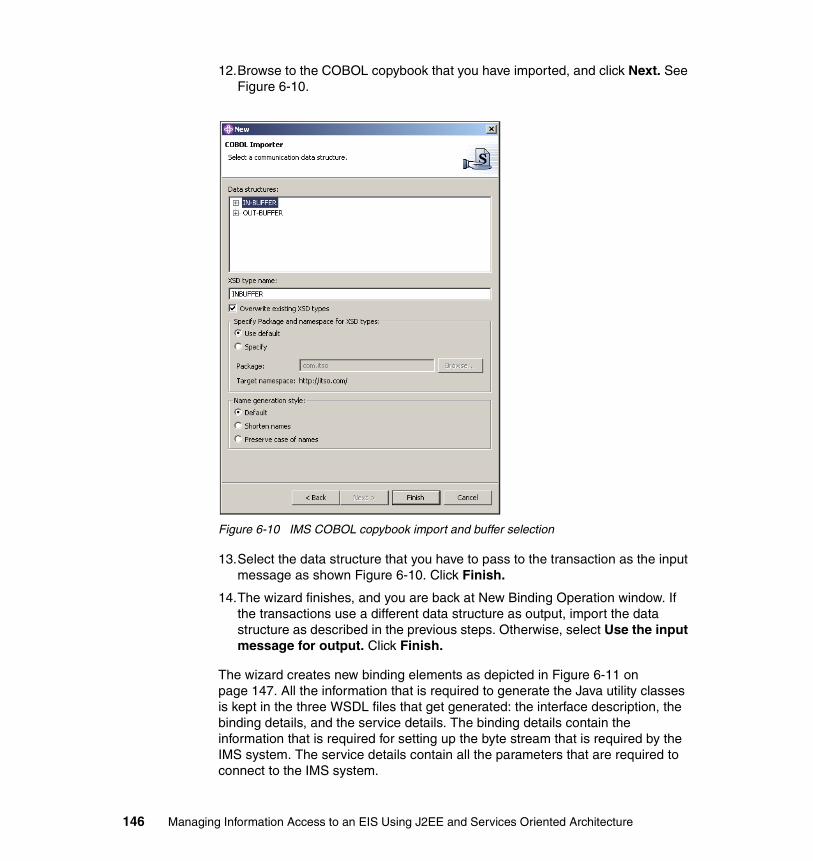
12.Browse to the COBOL copybook that you have imported, and click Next. See Figure 6-10.
Figure 6-10 IMS COBOL copybook import and buffer selection
13.Select the data structure that you have to pass to the transaction as the input message as shown Figure 6-10. Click Finish.
14.The wizard finishes, and you are back at New Binding Operation window. If the transactions use a different data structure as output, import the data structure as described in the previous steps. Otherwise, select Use the input message for output. Click Finish.
The wizard creates new binding elements as depicted in Figure 6-11 on page 147. All the information that is required to generate the Java utility classes is kept in the three WSDL files that get generated: the interface description, the binding details, and the service details. The binding details contain the information that is required for setting up the byte stream that is required by the IMS system. The service details contain all the parameters that are required to connect to the IMS system.
146 Managing Information Access to an EIS Using J2EE and Services Oriented Architecture

Figure 6-11 IMS service bindings including the InvokeTrader operation
To create the Java utility classes, select the services WSDL file (for example, TraderEISIMSService.wsdl), and select Enterprise Services → Generate Service Proxy. In the wizard that opens, you can accept all defaults. However, in the last window you have to select the proxy style and the operation. We recommend that you select Client Stub style. This results in the generation of methods at the proxy class that map to the defined methods in the binding WSDL file.
In addition to the proxy class, the wizard generates the Java utility classes that we used in the following steps. You create Java classes that map to the input and output data structures that you have selected from the COBOL copybook. These classes can be used to set the input and get the output of the operation. The wizard also generates Web Services Invocation Framework (WSIF) format handlers that are used by the underlying WSIF environment to generate the byte stream that is sent to the IMS system. Although did not use WSIF to invoke the IMS transaction, we used the format handlers to generate the byte stream.
Chapter 6. EIS integration using Java Message Service 147

We also recommend that you test the generated artifacts in a J2SE environment right away. For this purpose, we suggest that you create a JUnit test case for the proxy class:
1. Highlight the proxy class in the Navigator view and select File → New → Other from the menu bar.
2. Go to Java → JUnit.
3. Select Test Case and click Next.
You can accept the defaults but make sure that you check all options at the bottom of the window as depicted in Figure 6-12.
Figure 6-12 Generate a JUnit test case
4. In the next window, select the operation that you have defined in the Service Creation wizard and click Finish.
In the test class that gets generated, you have to add a class variable with the type of the proxy class, for example TraderEISProxy in our scenario. Instantiate the class in the setUp() method, and de-reference it in the tearDown() method. Finally, you also have to code the test method. Example 6-1 on page 149 shows the code to invoke the Trader method.
148 Managing Information Access to an EIS Using J2EE and Services Oriented Architecture

Example 6-1 JUnit test class
public void testInvokeTrader() {// Initialize boolean result = false;int inSize = new com.itso.ims.ibmcobol.INBUFFERFormatHandler().getSize();INBUFFER in = new INBUFFER();OUTBUFFER out = new OUTBUFFER();
try {// Set input to call Buy
in.setIn__ll((short) inSize); in.setIn__zz((short) 0); in.setIn__trcd("TRADERBl"); in.setRequest__type("Buy_Sell"); in.setCompany__name("IBM"); in.setUserid("TestUser"); in.setNo__of__shares__dec((short) 5); in.setUpdate__buy__sell("1");
// Call transaction System.out.println("Calling IMS transaction ..."); out = tp.InvokeTrader(in);
// Transaction completed System.out.println("Transaction completed."); result = true;
} catch (WSIFException e) { System.out.println("In catch block ..."); e.printStackTrace();
} finally { assertTrue(result);
}}
You run the JUnit test class by selecting Run → Run from the menu bar. In the window that opens, select JUnit and click New. Make sure that the test class is entered correctly and click Run.
The generation process of the Java utility classes can also be started as a batch job. WebSphere Studio Application Developer Integration Edition provides templates for XML-based configuration files and a executable to run the service and helper class generation in the background. We recommend that you use the
Note: If you cut and paste code into the generated Java stub, many types are not recognized because the corresponding import statements are missing. Right-click in the code and select Source → Organize Imports to let the tool create the statements for you.
Chapter 6. EIS integration using Java Message Service 149

batch import and generation if your IMS transactions and COBOL copybooks change frequently. Refer to the WebSphere Studio Application Developer Integration Edition Help for more details (search for batch import).
IMS transactions often return multi-segmented messages which means that they return a byte stream with variable length and data structures. The WebSphere Studio Application Developer Integration Edition tools cannot generate the WSIF format handlers and helper classes for multi-segmented messages. A workaround is to generate helper classes for the different segments by defining an artificial operation that returns each segment. The segment data type can be selected from the COBOL copybook for that transaction. Having created the WSIF format handlers for the segments, development of code to parse the byte stream returned by the IMS transaction is facilitated.
Creating the IMS access featureAs described in section “The stock trade scenario” on page 137, the IMS feature consists of the utility classes and a session bean. The session bean implements the feature interface.
We created the session bean using the J2EE tools of WebSphere Studio Application Developer Integration Edition. To do this:
1. Go to the J2EE perspective, and select the EJB project in the J2EE Hierarchy view.
2. Open the EJB generation wizard by selecting New → Enterprise Bean.
In the wizard, you select the bean type (for example, session bean) and provide names for the bean and the Java package. For the feature bean, you also have to generate a local interface, so make sure to check Local client view.
Furthermore, you can select the interface that the session bean extends for both the local and remote view. In this case, you have to create the feature Java interface as depicted in Figure 6-7 on page 140. Alternatively, you can add the methods to the bean implementation class and promote the methods to the local and remote interface, respectively.
Example 6-2 on page 151 shows the code for the Trader IMS feature of the interface operations. In the runTransaction() method, we used the J2C API to access the IMS system. The INBUFFER and OUTBUFFER Java classes and the corresponding WSIF format handlers are generated by the WebSphere Studio Application Developer Integration Edition wizard.
150 Managing Information Access to an EIS Using J2EE and Services Oriented Architecture
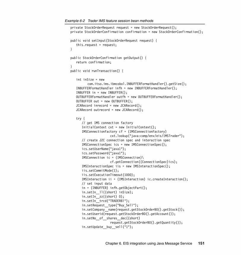
Example 6-2 Trader IMS feature session bean methods
private StockOrderRequest request = new StockOrderRequest();private StockOrderConfirmation confirmation = new StockOrderConfirmation();
public void setInput(StockOrderRequest request) {this.request = request;
}
public StockOrderConfirmation getOutput() {return confirmation;
}public void runTransaction() {
int inSize = new com.itso.ims.ibmcobol.INBUFFERFormatHandler().getSize();
INBUFFERFormatHandler infh = new INBUFFERFormatHandler();INBUFFER in = new INBUFFER();OUTBUFFERFormatHandler outfh = new OUTBUFFERFormatHandler();OUTBUFFER out = new OUTBUFFER();JCARecord inrecord = new JCARecord();JCARecord outrecord = new JCARecord();
try {// get IMS connection factoryInitialContext cxt = new InitialContext();IMSConnectionFactory cf = (IMSConnectionFactory)
cxt.lookup("java:comp/env/eis/IMSTrader");// create J2C connection spec and interaction specIMSConnectionSpec ics = new IMSConnectionSpec();ics.setUserName("java1");ics.setPassword("java1");IMSConnection ic = (IMSConnection)\
cf.getConnection((ConnectionSpec)ics);IMSInteractionSpec iis = new IMSInteractionSpec();iis.setCommitMode(1);iis.setExecutionTimeout(1000);IMSInteraction ii = (IMSInteraction) ic.createInteraction();// set input data in = (INBUFFER) infh.getObjectPart();in.setIn__ll((short) inSize);in.setIn__zz((short) 0);in.setIn__trcd("TRADERBl");in.setRequest__type("Buy_Sell");in.setCompany__name(request.getStockOrderBO().getStock());in.setUserid(request.getStockOrderBO().getAccount());in.setNo__of__shares__dec((short)
request.getStockOrderBO().getQuantity());in.setUpdate__buy__sell("1");
Chapter 6. EIS integration using Java Message Service 151

inrecord.setFormatHandler(infh);outrecord.setFormatHandler(outfh);// invoke IMS transaction and store resultii.execute(iis,inrecord,outrecord);ii.close(); ic.close();out = (OUTBUFFER) outfh.getObjectPart();// set resultconfirmation.setMessage("Transaction completed successfully");confirmation.setStockOrderBO(request.getStockOrderBO());
} catch (NamingException e) {e.printStackTrace();confirmation.setMessage("Transaction failed");confirmation.setStockOrderBO(request.getStockOrderBO());
} catch (ResourceException e) {e.printStackTrace();confirmation.setMessage("Transaction failed");confirmation.setStockOrderBO(request.getStockOrderBO());
}}
In the try or catch block of the runTransaction() method, you find statements to create and initialize the J2C connection spec and interaction spec objects. Also, we created a J2C connection at the J2C connection factory and initialized the J2C interaction. The execute() method at the J2C interaction requires that input and output parameters extend the interfaces javax.resource.cci.Record and javax.resource.cci.Streamable. To make use of the WSIF format handlers for byte stream generation, we created the JCARecord class that implements both interfaces. Example 6-3 shows the JCARecord class. The read() and write() operations are used by the J2C framework to access the byte stream.
Example 6-3 JCARecord utility class
package com.itso;import java.io.IOException;import java.io.InputStream;import java.io.OutputStream;import javax.resource.cci.Record;import javax.resource.cci.Streamable;import org.apache.wsif.providers.jca.WSIFFormatHandler_JCA;
public class JCARecord implements Record, Streamable {private WSIFFormatHandler_JCA formatHandler_ = null;
public WSIFFormatHandler_JCA getFormatHandler() {return formatHandler_;
}public void setFormatHandler(WSIFFormatHandler_JCA formatHandler) {
formatHandler_ = formatHandler;
152 Managing Information Access to an EIS Using J2EE and Services Oriented Architecture

}public String getRecordName() {
return null;}public void setRecordName(String arg0) {}public void setRecordShortDescription(String arg0) {}public String getRecordShortDescription() {
return null;}public void read(InputStream arg0) throws IOException {
if (formatHandler_ != null) formatHandler_.read(arg0);else throw new IOException("FormatHandler has not been set");
}public void write(OutputStream arg0) throws IOException {
if (formatHandler_ != null) formatHandler_.write(arg0);else throw new IOException("FormatHandler has not been set");
}public Object clone() {
return null;}
}
As you can see in the runTransaction() method in Example 6-2 on page 151, the J2C connection factory is retrieved by passing a local JNDI name starting with java:comp/env. Make sure that you have defined the connection factory in the EJB deployment descriptor. Go to the References tab of the EJB deployment descriptor, highlight the feature session bean, and click Add. Figure 6-13 on page 154 shows the reference for the Trader IMS feature.
Chapter 6. EIS integration using Java Message Service 153

Figure 6-13 Create a reference to the J2C connection factory
As discussed in Chapter 3, “Scenario overview and design” on page 65, we focused on creating a simple but complete sample scenario. In real environments, we recommend that you design a comprehensive framework for features and feature registration. You should address topics such as dynamic registration of features and exception handling. Also, you should consider whether to generate features from models by using the pattern and code template mechanisms of Rational XDE Developer.
Creating the integration beanAn EIS component typically comprises a set of features. The integration bean is the channel to all the features of an EIS component. We have implemented the integration bean as EJB session bean that provides an invoke() method. The input and output for the invoke() method are business objects. Based on context information and business object that are passed, the integration bean decides which feature to call (see Example 6-4 on page 155).
154 Managing Information Access to an EIS Using J2EE and Services Oriented Architecture

Example 6-4 Trader IMS integration session bean method
public StockOrderConfirmation invoke(StockOrderRequest request){char context[] = request.getContext().toCharArray();StockOrderConfirmation confirmation = new StockOrderConfirmation();confirmation.setStockOrderBO(request.getStockOrderBO());
switch (context[0]) {// TraderIMS featurecase 't':// call TraderIMS featuretry {
InitialContext cxt = new InitialContext();TraderIMSFeatureLocalHome localhome = (TraderIMSFeatureLocalHome)
cxt.lookup("java:comp/env/ejb/TraderIMSFeature");TraderIMSFeatureLocal local = localhome.create();local.setInput(request);local.runTransaction();StockOrderConfirmation result = local.getOutput();return result;
} catch (NamingException e) {e.printStackTrace();confirmation.setMessage("Feature not available");return confirmation;
} catch (CreateException e) {e.printStackTrace();confirmation.setMessage("Feature not available");return confirmation;
}// no feature founddefault:confirmation.setMessage("Feature not registered");return confirmation;
}}
For the Trader integration bean, we implemented a simple decision and used a switch statement. Example 6-4 shows the invoke() method of the session bean. We directly called the feature by passing the business object. No data transformation should be implemented here, because data mapping is performed by the feature classes. To call the feature session beans, we again used a local reference that was defined in the EJB deployment descriptor. The definition is similar to the process of defining a reference to the J2C connection factory for the feature session bean. Make sure that you add a Local reference and use the Local home and bean interfaces when calling the features. Promote the invoke() method to the remote interface of the integration session bean to be able to call the EIS component remotely.
Chapter 6. EIS integration using Java Message Service 155

6.4.3 Enabling the EIS component using JMSIn our approach for EIS integration, the EIS component is called from a system process that is implemented using BPEL technology. WebSphere Studio Application Developer Integration Edition provides a number of tools to create services from artifacts such as Java classes and EJBs. The service definitions are kept in three WSDL files: interface definition, binding details, and service location details. Furthermore, the tool provides wizards to generate different service bindings for various technologies (for example, EJB, JMS, and SOAP Web services). The service WSDL file that describes the actual location of the service can be easily imported into a BPEL process as a BPEL partner link.
We evaluated the different options to enable the EIS component to be called from a BPEL system process. We recommend that you use the service enablement wizards if EJB binding is required. If JMS binding is needed, we found that development of JMS artifacts such as sender beans and message-driven EJBs is a better approach. In our view, JMS enabling the EIS component by manually creating JMS code has the following advantages:
� JMS APIs are called directly and no WSIF calls are required, which means there is no overhead that may lead to performance issues
� The architect and developer have more options to select the message type and format of the data that is sent over the wire
� JMS connection factories, destinations, and interaction parameters can be defined more easily
� JMS topics can be used to broadcast messages to multiple EIS components
For the Trader EIS component, we have developed an MDB that calls the Trader Integration session bean. Example 6-5 on page 157 shows the onMessage() method for the bean. We chose to send serialized Java objects that are encapsulated in the JMS message type ObjectMessage. The Java data type that is accepted as input is a StockOrderRequest business object. The TraderIntegration session bean is called using its local interface.
When creating the MDB using the EJB Creation wizard, you are asked to enter a name for the JMS listener port. A JMS listener is a WebSphere specific notion of the queue the MDB listens to. You need to configure the JMS listener port for the WebSphere test environment.
Having created a test server, you open its configuration editor by double-clicking the test server in Server Configuration view. First, go to the JMS tab to set up JMS connection factories and destinations. Make sure that you enter the destination to the list of queues at the top of the editor window. Click Add in the EJB tab of the editor to set up the JMS listener ports. Make sure that you select to start the port in the JMS listener creation wizard.
156 Managing Information Access to an EIS Using J2EE and Services Oriented Architecture
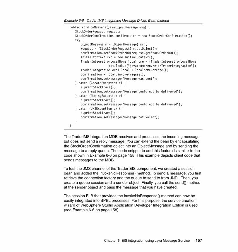
Example 6-5 Trader IMS integration Message Driven Bean method
public void onMessage(javax.jms.Message msg) {StockOrderRequest request;StockOrderConfirmation confirmation = new StockOrderConfirmation();try {
ObjectMessage m = (ObjectMessage) msg;request = (StockOrderRequest) m.getObject();confirmation.setStockOrderBO(request.getStockOrderBO());InitialContext cxt = new InitialContext();TraderIntegrationLocalHome localhome = (TraderIntegrationLocalHome)
cxt.lookup("java:comp/env/ejb/TraderIntegration");TraderIntegrationLocal local = localhome.create();confirmation = local.invoke(request);confirmation.setMessage("Message was sent");
} catch (CreateException e) {e.printStackTrace();confirmation.setMessage("Message could not be delivered");
} catch (NamingException e) {e.printStackTrace();confirmation.setMessage("Message could not be delivered");
} catch (JMSException e) {e.printStackTrace();confirmation.setMessage("Message not valid");
}}
The TraderIMSIntegration MDB receives and processes the incoming message but does not send a reply message. You can extend the bean by encapsulating the StockOrderConfirmation object into an ObjectMessage and by sending the message to a reply queue. The code snippet to add this feature is similar to the code shown in Example 6-6 on page 158. This example depicts client code that sends messages to the MDB.
To test the JMS channel of the Trader EIS component, we created a session bean and added the invokeNoResponse() method. To send a message, you first retrieve the connection factory and the queue to send to from JNDI. Then, you create a queue session and a sender object. Finally, you call the send() method at the sender object and pass the message that you have created.
The session EJB that provides the invokeNoResponse() method can now be easily integrated into BPEL processes. For this purpose, the service creation wizard of WebSphere Studio Application Developer Integration Edition is used (see Example 6-6 on page 158).
Chapter 6. EIS integration using Java Message Service 157

Example 6-6 Trader IMS integration JMS client
public void invokeNoResponse(StockOrderRequest sor) {// invoke serviceContext jndiContext = null;QueueConnectionFactory queueConnectionFactory = null;QueueConnection queueConnection = null;QueueSession queueSession = null;Queue queue = null;QueueSender queueSender = null;ObjectMessage message = null;
try{ jndiContext = new InitialContext();
// Look up connection factory and queue queueConnectionFactory = (QueueConnectionFactory)
jndiContext.lookup("java:comp/env/jms/TraderQCF"); queue = (Queue) jndiContext.lookup("java:comp/env/jms/TraderQueue"); // Create connection. queueConnection = queueConnectionFactory.createQueueConnection(); // Create session from connection queueSession = queueConnection.createQueueSession(false,
Session.AUTO_ACKNOWLEDGE); // Create sender and text message.
queueSender = queueSession.createSender(queue); message = queueSession.createObjectMessage(); message.setObject(sor); // Send messages queueSender.send(message);}catch (NamingException e) { e.printStackTrace(); }catch (JMSException e) { e.printStackTrace(); }finally {
if (queueConnection != null) {
try { queueConnection.close(); }catch (JMSException e) {}
}}
}
To create a service:
1. Go to the Business Integration perspective and select File → New → Service built from.
2. Select EJB in the window that opens and click Next.
158 Managing Information Access to an EIS Using J2EE and Services Oriented Architecture

3. In the next window browse to the EJB and select the method that you wish to call from the BPEL process.
4. Click Next. You can accept the defaults for the service name and the names of the WSDL files and click Finish.
The wizards creates the three WSDL files that describe the service: its interface, the EJB binding details, and the EJB service location details. You can later include the EJB service as BPEL partner link into a BPEL process (see Chapter 9, “Integration into business processes” on page 241).
WebSphere Business Integration Server Foundation includes the extended messaging feature that extends the base JMS support and support for MDB by introducing container managed messaging. Additional types of EJBs, for example a sender EJB, are introduced and new management objects are available at the administration console to configure the environment for those beans. Although we have not attempted to use extended messaging in our sample scenario, we would recommend that you evaluate its use for real environments.
6.4.4 Deploying the EIS componentThe Trader EIS component consists of EJB modules including session EJBs, MDB, and Java utility classes. To deploy the component to the test environment or to a WebSphere Application Server instance, you have to create and configure the following administration objects for that server:
� A JAAS security alias for the IMS user on the IMS host. The alias is later used when creating the J2C connection factory.
� A J2C IMS connection factory to connect to the J2C IMS resource adapter.
� JMS connection factories for the MDB and for the sender bean of the EIS component’s client.
� JMS destinations and queues for the MDB and for the sender bean.
� A JMS listener port for the MDB.
Configuration of these resources is error-prone. In particular, mismatches when specifying JNDI names often cause issues. Even in production environments, we have seen misconfigurations (for example, for the JMS listener ports). To avoid bottlenecks and to be able to process many messages simultaneously, you might have to adapt the size of the thread pool for a JMS listener port.
Chapter 6. EIS integration using Java Message Service 159

6.5 Qualities of service for integration using JMSThe first sections of this chapter discussed the functional characteristics of MOM. Qualities of service refers to the non-functional requirements on a messaging infrastructure.
The basic non-functional requirements such as security, high-availability, and performance are addressed in various publications and redbooks. This section focuses on transactions in a mixed application server and messaging environment. Furthermore, it discusses management and problem determination in a complex messaging infrastructure.
6.5.1 TransactionsBusiness processes that are implemented in new composite applications and that integrate with legacy EIS systems often require transactional behavior across all components and systems. For instance, in our trading firm scenario, the debit of the customer’s account and the ordering request and its confirmation are tightly coupled. If the ordering request fails, the debit must be rolled back, because customers typically complain if their account is debited although no stock is added to their portfolio.
From a business perspective, the sending of the request message from the business process, the transport of the message over the network, the invocation of the business process, and the sending and receiving of the confirmation message must form a single transaction. From a technical perspective, the requirement results in a distributed transaction across business process, integration components, and EIS system. Although distributed transactions involving physically remote systems are technically possible, a number of issues are related to this approach. Among others, performance of distributed transactions over a network is often poor because of the complex interaction patterns that are required (for example, for the XA protocol).
A better solution is provided by MOM. The overall transaction scope is split into multiple transactions of smaller scope. Figure 6-14 on page 161 depicts the logical architecture of the integration building block that uses JMS including the MOM. The basic idea is to rely on the MOM’s ability to guarantee the delivery of a message once it is handed over to the MOM. This characteristic, often referred to as assured delivery, allows you to split the actual technical transaction into three separate transactions of local scope. Hand-over of the message from application server to the MOM is the first transaction, delivering the message to the application server on the EIS host and sending the reply back to the MOM is the second, and finally, another transaction is required to receive the reply in the application server.
160 Managing Information Access to an EIS Using J2EE and Services Oriented Architecture

Figure 6-14 Transactions in a mixed application server - MOM environment
Figure 6-14 visualizes the transactional scope with the red circles. On the application host, the transaction comprises the system process, the JMS service, the JMS connector, and the JMS provider. On the EIS host, JMS provider, JMS connector, and the EIS component are involved in the transaction. This transaction also includes the EIS system, if the technology to call the EIS system functions supports transactions. In the Trader scenario, the IMS function is called using the J2C-compliant IMS connector that supports XA transactions.
Chapter 9, “Integration into business processes” on page 241 addresses the transactional characteristics of the BPEL business process and the JMS components on the application host.
On the EIS side, the EIS component is a J2EE component consisting of EJBs that are deployed on WebSphere Application Server. The application server, WebSphere MQ, the J2C IMS connector, and the IMS subsystem on the zSeries host support XA transactions. That is, their transaction managers are able to interact with the WebSphere transaction coordinator to assure a distributed transaction across these components.
To enable the EIS component for transactions, the following settings and activities are required:
� The JMS queue connection factory that is used for the JMS listener port of the MDB has to be enabled for XA transactions by checkmarking the XA enable option.
J2EE ApplicationServer
Application Host
JMSService
SystemProcess
JMSProviderJMS
Connector
J2EE Application Server
Transactional Scope
HostY
HostX
HostZ
NetworkJ2EE Application
Server
EIS Host
EISComponent
JMSProvider
MDB
JMSConnector
MOM-Enabled
Transactional Scope
J2EE Application Server
Chapter 6. EIS integration using Java Message Service 161

� For the EIS component session beans, the transaction type of the methods has to be set correctly (Supports, Required).
� The JCA IMS connector supports XA transactions out-of the-box but ensures that the IMS connect and IMS subsystem on the zSeries host are enabled to participate in a XA transaction.
If a confirmation message is required for the calling business process, the sender bean that creates and puts the message on the reply queue also has to be enabled to participate in the transaction by setting the appropriate transaction type.
In case of failures and system outages, the WebSphere transaction coordinator rolls the transaction back and the message is not deleted from the WebSphere MQ queue. If WebSphere itself fails while a transaction is in-flight, the transaction continues as soon as the application server recovers. The IMS Connect and the IMS system, however, do not always rollback or recover the transactions correctly. We have encountered situations where manual interaction on the IMS side was required if transactions failed.
To be able to resolve these issues, detailed information about the messages received and processed in the EIS component is needed. Therefore, a powerful and reliable logging and audit mechanism across the application server and messaging infrastructure is useful. We discuss this requirement in 6.5.2, “Problem determination and resolution” on page 162.
6.5.2 Problem determination and resolutionWebSphere Application Server and WebSphere MQ log relevant events and exceptions in log files on the hosts. We also recommend that all application artifacts, such as business processes and EJBs log activities, messages, and exceptions, generate log events or log messages. To detect problems and to identify the probable cause for failures, the WebSphere Administrative Console provides functions to visualize and analyze the log files.
The WebSphere Administrative Console provides the single entry point to a WebSphere cluster. For the integration building block using JMS, however, the application host and the EIS host typically belong to separate WebSphere clusters. Problem detection and resolution can become cumbersome if many different log files on separate host systems have to be checked.
162 Managing Information Access to an EIS Using J2EE and Services Oriented Architecture

Figure 6-15 Logging mechanism in complex messaging environment
To facilitate problem determination and resolution in the complex environment, we recommend that you establish a common policy and procedure for logging and auditing of activities and exceptions. To provide a single view of all activities performed and messages delivered in a distributed environment, a staged log mechanism can be implemented. Figure 6-15 shows the environment for staged logging in a mixed application server and MOM environment.
At the first stage, log messages are recorded in log data stores at the physical node the corresponding software component is running on. The data store can be a flat file, but also a database or a persistent message queue can be used to store the logs.
At a second stage, all log events are extracted from the log data stores of the physical nodes. Log events extracted can include messages that are delivered by the MOM infrastructure and that provide detailed information about how requests have been processed in the application and EIS component. The extraction mechanism can be based on scripts running at customizable time intervals or can run continuously in parallel to first stage logging. The extracted
Logging Host
Log and AuditData Warehouse
J2EEApplication
Server
JMSProvider
Application Host
J2EEApplication
Server
JMSProvider
EIS
LogExtraction
andArchiving
LogExtraction
andArchiving
EIS Host
Chapter 6. EIS integration using Java Message Service 163

events can be stored in a central data warehouse. Sophisticated analysis can be performed on the database. For example, log events for all messages related to a specific application request can be combined and analyzed together.
The main reason for introducing a staged approach rather than setting up a central log datastore is that log events are available on each node independent of the availability of the centralized log service. Particularly, detection and resolving of failures is still possible even if the system affected is disconnected from all other infrastructure components.
In WebSphere Business Integration Server Foundation the WebSphere Common Event Infrastructure (CEI) recently became available. WebSphere CEI is an implementation of a consistent, unified framework for the creation, transmission, persistence, and distribution of a wide range of business events, such as log and audit messages. CEI is based on the Common Base Event (CBE) format which was proposed as a new standard to the Organization for the Advancement of Structured Information Standards (OASIS). Although we have not attempted to include WebSphere CEI into the design presented in this chapter, we recommend that you evaluate its use for real environments.
164 Managing Information Access to an EIS Using J2EE and Services Oriented Architecture

Chapter 7. Using Web services
This chapter describes how to use the Web services technology in a scenario of enterprise system integration. After a high-level overview on Web services technology, it focuses on how to develop Web services with particular attention to quality of service using IBM products.
7
© Copyright IBM Corp. 2005. All rights reserved. 165
7.1 Web services overviewInformation exchange between applications is one of the oldest issues in computer science history. Much technology has been invented to solve this common need. As the technology has evolved, many solutions have been provided by software vendors or vendor consortia. Although the need to standardized was compelling, many market leaders tried to maintain a dominant position, which often hampered interoperability standards.
In recent years, the market for vertical applications and solutions has become saturated, and some leaders have emerged. Today, customers want to know how to integrate the systems that they have acquired.
The Internet phenomenon introduced a well known and widely spread networking infrastructure which is used mainly for human-to-computer communication. One result has been to use the same infrastructure that unified the user interface to attempt to unify the systems interfaces.
Web services were introduced to enable application-to-application communication based on the following widely accepted open standards:
� Extensible Markup Language (XML), the universal language that describes data in an hierarchical manner that is based on tags.
� Hypertext Transfer Protocol (HTTP), the Internet protocol that provides a simple request-response paradigm.
Using open standards provides broad interoperability among different vendor solutions. These principles mean that companies can implement Web services without having any knowledge of the service consumers, and vice versa. This facilitates just-in-time integration and allows businesses to establish new partnerships easily and dynamically.
This chapter focuses on the integration capabilities of Web services. If you need a deeper explanation of Web services basics, see 7.6, “Further information” on page 195.
7.1.1 Service conceptOne of the most powerful concepts of Web services is the service concept. The service concept is an evolution of the component idea in the software engineering field. The basic idea is to decompose a system in well-defined reusable blocks. The service extends the component idea, because it goes beyond the software development field to realize the cooperation of heterogeneous systems.
166 Managing Information Access to an EIS Using J2EE and Services Oriented Architecture

Web services defines three terms that are related to the service concept:
� PortType is the interface exposed.� Binding describes the communication details on a specific protocol.� Service describes the address of the service.
These concepts are so general that they are applicable to any kind of software interaction. It does not matter what, how, and where the service is provided. Thus, we have a general concept that we can used at any level of our software architecture.
The only issue that we need to think about is how to design the building blocks of our software to meet the requirements of internal and external reusability, modularity, and change adaptability.
The standardization process has produced a formal document that expresses the essence of a service: the Web Services Description Language (WSDL) document. The W3C organization hosts this specification which, at the time of writing this book, has reached version 1.2.
The next step is to handle a service without the pain of needing to handle all the technical details. We need a software library that after inspecting WSDL is able to invoke services as a black box. In the Java world, the Apache Software Foundation provides Web Services Invocation Framework (WSIF) as a tool to achieve this task. WSIF was developed originally by IBM, then it was donated to Apache. WSIF is different from the JAX-RPC API, because it can invoke any kind of service, with any kind of binding, not only SOAP services. WSIF extends the purpose of a SOAP-invocation API to become a shaped tool for a new era of enterprise application integration (EAI). For more details on the Web Services Invocation Framework, see:
http://ws.apache.org/wsif/
7.1.2 Web services evolutionNew Web services specifications are announced constantly, which can give the impression that Web services are a volatile technology not yet ready for mission critical applications. Although the standardization roadmap has many open topics, there are many specifications that are well defined and solid enough to give us a first set of powerful features.
We can classify the evolution of the Web services standardization in three phases:
� Connection: addresses the communication between the parties� Quality of service: addresses security and reliability� Enterprise: addresses workflow, transactions, and system management
Chapter 7. Using Web services 167

See Figure 7-1 for an illustration of these phases.
Figure 7-1 The Web services evolution phases
The first phase can be considered closed. Also, the work of the Web services Interoperability organization in this area has consolidated with the release of Web Services Interoperability (WS-I) Basic Profile at the time that this book was published.
These three phases should not be considered as temporal phases but also as logical ones. In fact, some topics of the third phase already have a first development, while other topics in the second phase are only defined.
In our opinion, Web services technology has reached stability in the communication area. So, it is ready for enterprise implementations that need a interoperable protocol to interconnect different systems. There are many open matters, which will be addressed in the next few years as Web services gain wider deployment.
For further information about the Web services roadmap, see WebSphere Web Services Information Roadmap, REDP-3854.
168 Managing Information Access to an EIS Using J2EE and Services Oriented Architecture

7.2 Web services for EIS integrationIn general Web services are appreciated for the following reasons:
� Interoperability
Any Web service can interact with any other Web service. Thanks to SOAP, the new standard protocol supported by all of the major vendors (and most of the minor ones too), the difficulties of converting between CORBA, DCOM, and other protocols should be over. Because Web services can be written in any language, developers do not need to change their development environments to produce or to use Web services.
� Ubiquity
Web services communicate using HTTP and XML. Therefore, any device which supports these technologies can both host and access Web services. Soon, Web services will be present in phones, cars, and even soda machines. If the soda supplies are getting low, then soda machine can contact the local supplier's Web service via a wireless network and can order what it needs.
� Low barrier to entry
The concepts behind Web services are easy to understand. Many vendors such as IBM and Microsoft offer tools that allow developers to quickly create and deploy Web services. In addition, some of these tools allow pre-existing COM components and JavaBeans to be easily exposed as Web services.
� Industry support
All of the major vendors are supporting SOAP and the surrounding Web services technology. For example, WebSphere Application Server supports these technologies inside the J2EE architecture, and the Microsoft.NET platform supports all the proprietary Microsoft languages.
The following sections explain why Web services are ready for an extensive deployment in scenarios that integrate business partners and that expose existing enterprise information systems (EIS).
7.2.1 Integrate business partnersA current business and technology challenge is to accelerate inter-company communication to gain more reactive business. Web services provide a low cost technology to realize this kind of need. When a new technology is introduced in the business activity, it is important for technology to offer a strong quality of service.
Chapter 7. Using Web services 169

In the scenario (described in Chapter 3, “Scenario overview and design” on page 65), we introduced Web services technology because the relationship between the bank and the stock analyst firm is changeable partnership and cannot justify the implementation of a private communication infrastructure. The bank wants to provide a new service which prevents its customers from buying stocks that fluctuate wildly in value. To give impartial advice, the bank relies on an external information service that is provided by a specialized stock analyst firm.
As in our scenario, there are several situations that have similar conditions and requirements:
� The business does not justify a private network.
� There is a need to exchange information with a remote partner.
� The service request does not have a side effect on the remote system (basic inquiry).
� The service request triggers a remote transaction; however, that transaction can be isolated by a local one.
� There is a need for quick implementation.
Web services technology can provide answers to each of these requirements.
7.2.2 Expose the EISIn almost all organizations, it is common to find a great variety of software platforms provided by different software vendors. In addition to mainframe solutions, there are many vertical solutions for ERP, eCommerce, Office Automation, CRM, and so on. There is also horizontal application technology for client and server computing such as J2EE application servers and Microsoft.Net. Niche technology (for example PHP, Perl, Python, and Borland Delphi) can also be used.
To make this different software work together, there are two options:
� Create an ad-hoc point-to-point translator.� Modify all the components to speak a common language.
The first option leads potentially to the implementation of (n-1)! translator. The second option, in the worst case, leads to the implementation of n translator. In the recent years, many software vendors have provided Web services implementation. The choice to use the Web services as a common language is one of the least expensive and most viable options.
Many legacy EIS solution do not offer Web services interfaces, or if they do offer an interface, it often lacks in terms of features. So, we suggest that you wrap
170 Managing Information Access to an EIS Using J2EE and Services Oriented Architecture

legacy systems with business integration middleware. The business integration middleware can interact with the legacy system through a native protocol and can expose selected services through Web service paradigms.
The benefits of this type of solution are that is:
� Exposes only a subset of services.
� Lets the Web services platform evolve smoothly — detached from the legacy system.
� Adds another layer and increases the EIS isolation, giving you more control of security constraints.
Legacy interfaces are often unsuited to be used by new applications. So, it is a good idea to wrap these interfaces with a logic that transforms and aggregates the information.
Figure 7-2 outlines a possible architecture that exposes the EIS with a Web services interface. In addition to the EIS, there is an adapter for the protocol translation.
Figure 7-2 Exposing the EIS with a Web services interface
We can expose the EIS is two ways:
� SOAP enabler
The back-end service is exposed as is. This option needs only a configuration task.
� Business Process Choreographer
The back-end service is adapted to the new needs. Here, we have a re-engineering task to develop a process that exposes a new interface. This process can handle data transformation and compose some legacy services to give a more complete service.
Chapter 7. Using Web services 171
The two ways can coexist. In general, we have many legacy services and in many cases one solution is not better than the other. These different ways to provide the service are transparent to the client, who sees only the service interface as described by WSDL.
In our integration scenario, we developed three different clients:
� J2EE Web application
This application can use the legacy service without the SOAP mediation. This solution does not break the service-oriented architecture, because the legacy service can be exposed as an enterprise service with bindings such as EJB, JCA, or JMS. The client can even be deployed on the same application server that hosts the connector.
� J2EE client
Although a J2EE client can use the traditional RMI/IIOP protocol, the Web service approach has some benefits. The SOAP protocol is often easier to configure with firewalls than IIOP. The service model promotes separation between the service provider and the consumer. Finally, if you have different types of clients, it is simpler to run and test one interface.
� Other SOAP client
In today’s computing environment, almost all programming languages have a SOAP API. So, we can have access to our EIS virtually everywhere in the enterprise.
7.3 Service-oriented architectureTo better comprehend Web services technology, we need to understand its place in the more general service oriented architecture (SOA). This section describes the technology stack that supports the SOA. For a detailed description of SOA, see 7.6, “Further information” on page 195.
Figure 7-3 on page 173 describes briefly the layers of the SOA abstraction.
172 Managing Information Access to an EIS Using J2EE and Services Oriented Architecture
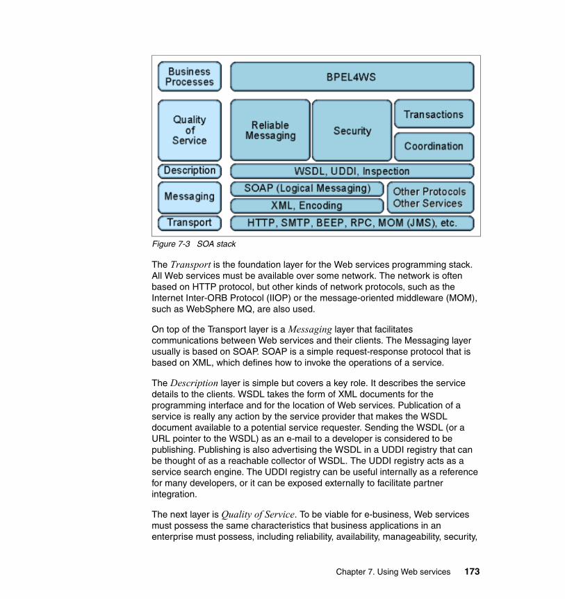
Figure 7-3 SOA stack
The Transport is the foundation layer for the Web services programming stack. All Web services must be available over some network. The network is often based on HTTP protocol, but other kinds of network protocols, such as the Internet Inter-ORB Protocol (IIOP) or the message-oriented middleware (MOM), such as WebSphere MQ, are also used.
On top of the Transport layer is a Messaging layer that facilitates communications between Web services and their clients. The Messaging layer usually is based on SOAP. SOAP is a simple request-response protocol that is based on XML, which defines how to invoke the operations of a service.
The Description layer is simple but covers a key role. It describes the service details to the clients. WSDL takes the form of XML documents for the programming interface and for the location of Web services. Publication of a service is really any action by the service provider that makes the WSDL document available to a potential service requester. Sending the WSDL (or a URL pointer to the WSDL) as an e-mail to a developer is considered to be publishing. Publishing is also advertising the WSDL in a UDDI registry that can be thought of as a reachable collector of WSDL. The UDDI registry acts as a service search engine. The UDDI registry can be useful internally as a reference for many developers, or it can be exposed externally to facilitate partner integration.
The next layer is Quality of Service. To be viable for e-business, Web services must possess the same characteristics that business applications in an enterprise must possess, including reliability, availability, manageability, security,
Chapter 7. Using Web services 173

an so on. All these qualities are discussed in 7.5, “Quality of service for Web services” on page 180.
The topmost layer in the stack is the Business Process layer (also known as Service Orchestration). This layer is implemented using Business Process Execution Language for Web Services (BPEL4WS0 or BPEL for short. It adds the capability to compose many services into a workflow to deliver a new complex business service. Although it is logically positioned as the last layer, it is independent of the Quality of Service layer. So, we can run a BPEL process even without security, reliability, coordination, and transaction.
7.4 Using Web services to integrate EISThis section shows how to make the EIS accessible through the Web services technology using a build to integrate approach. We used WebSphere Studio Application Developer Integration Edition to make the EIS accessible with a Web service interface.
7.4.1 WebSphere Studio Application Developer Integration Edition WebSphere Studio Application Developer Integration Edition V5.1.1, at its core, provides easy-to-use tools for creating reusable services out of a variety of back-end systems and for choreographing the interactions between those services using BPEL4WS.
WebSphere Studio Application Developer Integration Edition provides a toolbox for discovering, creating, and publishing Web services that are created from JavaBeans, DADX files, Enterprise JavaBeans, and URLs. You can also use Web services tools to create a skeleton JavaBean and a sample application from a WSDL document.
A Web service can be implemented from:
� An existing application (bottom-up), transforming an existing application into a Web service that includes the generation of service wrappers to expose the business functionality.
� An existing service definition (top-down), generating a new application skeleton from a service definition (WSDL).
WebSphere Studio Application Developer Integration Edition extends the Web service capabilities of WebSphere Studio Application Developer with a more service-oriented approach.
174 Managing Information Access to an EIS Using J2EE and Services Oriented Architecture

Business servicesAt the heart of the Integration Edition programming model are business services, which are used to consistently model different kinds of service providers. Services are the business functions of your enterprise, or of your business partners. You can use the integration tools to develop various types of services, including Web services, processes, EIS (J2EE Connector) services, JMS services, and so on. WSDL is used as the model for describing any kind of service.
Business processesA business process is a service implementation that represents a part of your business operations. It can be totally automated or may require human interaction at certain points. WebSphere Studio Application Developer Integration Edition provides a model that allows you to implement these processes in a very efficient graphical way.
The following sections discuss how to expose the developed process as a Web service, how to invoke a Web service inside the process, and what are the main related issues.
See 7.6, “Further information” on page 195 for reference information about WebSphere Studio Application Developer Integration Edition and how to develop Web services.
7.4.2 Expose the process as a Web serviceTo expose a process as a Web service is a simple activity. The business process engine of WebSphere Business Integration Server Foundation is based on the BPEL4WS language that uses the Web services concept.
BPEL states that any interface from the process and to the external world is a Web service and is physically described by a WSDL file. As a consequence, you need to establish only the details of the communication, which is called in Web services jargon, defining the binding.
The binding definition for a process is done during the last development phase, which is Generate Deploy Code. The deploy wizard of WebSphere Studio Application Developer Integration Edition shows all the interfaces of the process. The Interfaces for Partners section contains all the interfaces that the process exposes to its clients. For each interface (PortType), it is possible to select which binding to make available. For an example, see Figure 7-4 on page 176.
Chapter 7. Using Web services 175

Figure 7-4 Generate deploy code wizard: Selecting the bindings
For the SOAP/HTTP binding, it is possible to specify two options:
� IBM Web Services� Apache
The IBM Web Services engine is the newest of these options, and it implements the latest standard, including JSR 109 and JSR 101. It also it implements an optimized SOAP parser that makes it outperform many of its competitors. The Apache option is provided only for backwards compatibility reasons.
As you see in Figure 7-5 on page 177, the wizard shows a tree on the left pane, and for each interface, it is possible to define the binding details. For the SOAP/HTTP, you can choose:
� Document Style: RPC or DOCUMENT� Document Use: ENCODED or LITERAL� Router Address: the URL where the SOAP listener is available
176 Managing Information Access to an EIS Using J2EE and Services Oriented Architecture

Figure 7-5 Defining the SOAP style for the process binding
There are four possible combinations of style and encoding, but only the first two should be used:
� Document/literal
Provides the best interoperability between Java and non-Java implementations.
� RPC/literal
This is a good choice between Java implementations.
� RPC/encoded
Early Java implementations (WebSphere Version 4 and 5.0) supported this combination, but it does not provide interoperability. It is no longer supported by the WS-I Basic Profile, and you should avoid using this option.
� Document/encoded
Not often used in practice.
Important: If the process interface uses a message with complex types, the wizard does not permit the Document style to be selected. In this case, you must use the literal encoding to achieve interoperability with Business Process Choreographer. In fact, Business Process Container can invoke only Web services in Document/literal and RPC/literal style Web services.
Chapter 7. Using Web services 177

To successfully expose the process via SOAP/HTTP, there are some product behaviors that the process developer should keep in mind:
� The SOAP engine does not support a capital letter as the first letter of the operation name.
� The SOAP engine does not support operations that use the same message as input and output.
� The generator of Web services (WSDL2Java) cannot run if the WSDL imports files (for example, XSD files) from a different directory than it is in.
This information affects how you implement the business process interface as defined in a WSDL file.
7.4.3 Invoke a Web serviceIn a BPEL process, a partner link is a 2-way relationship between the process and the external partner. In the wizard that is used to Generate Deploy Code, under the Referenced Partner branch, there are all the outgoing partner links that are defined inside the process. For each partner link you can also specify the service that implements that interface as shown in Figure 7-6 on page 179.
Important: By default WebSphere Studio Application Developer Integration Edition generates a BPEL file that has an interface that violates the first two of these rules. When you export BPEL files from WebSphere Business Integration Modeler, they violate the last rule.
178 Managing Information Access to an EIS Using J2EE and Services Oriented Architecture

Figure 7-6 Defining the service and the port for a partner link
The only options that you may specify are which service and which port to use if there are more than one. This means that all the details about the binding and the service are in the WSDL file that is provided. In particular, the URL of the Web service to invoke is hard coded in the WSDL.
To avoid confusion, it is important that during testing the external Web service is reached from the developer’s workstation in the same manner as it will be called in the target environment.
Normal production environments have the servers protected by two or more firewalls. In a business-to-business integration using Web services, the applications or the processes need to access the Internet over the HTTP protocol. There are several ways to obtain this objective, and we suggest using the Web Services Gateway to gain flexibility.
The Web Services Gateway is a product feature implemented in WebSphere Application Server Version 5 Network Deployment. The primary function of the Web Services Gateway is to map an existing WSDL-defined Web service to a new service that is offered by the Gateway to others. The Gateway thus acts as a
Chapter 7. Using Web services 179
proxy. External services are imported into the Gateway and made available internally to the enterprise as proxy services . Likewise, internal services are imported into the Gateway and made available as proxy services externally. These services are also published to the relevant UDDI directories where required.
7.5 Quality of service for Web servicesQuality of service (QOS) refers to the capability of a platform to provide a better service to a selected application.
It is a challenge to build systems that deliver extremely high levels of service because many variables need to be considered. The success of an application depends on scalability, performance, availability, security, and manageability, among other things, and all these are critical considerations if you are to avoid failure.
In terms of Web Services, QOS covers a range of techniques that match the needs of service requestors with those of the service provider's that are based on the network resources that are available.
This section describes some considerations about QOS in a Web service context. It does not discuss the scalability and availability topics, because these issues are inherent to the underlaying middleware platform that hosts the Web services. For details of these topics as related to the WebSphere platform see the references in 7.6, “Further information” on page 195.
7.5.1 PerformanceOften non-functional requirements are overlooked. It can happen that a project manager faces the performance issue only in a production environment when the performance challenge should be considered from the design phase of the project.
One of the major drawbacks of the Web services technology is the performance issue. The great interoperability of Web services is often paid for in terms of the increased time for processing the message. XML parsing is always a heavy job, even as parsers are becoming smarter.
The service designer should consider that service granularity has a significant impact on the response time of Web services and decide on the level of granularity of the functions to be exposed as Web services to avoid unnecessary message exchanges across the Internet.
180 Managing Information Access to an EIS Using J2EE and Services Oriented Architecture

As a performance rule, the service designer should strive to publish coarse grained services that accept all necessary parameters and information, thereby allowing the service provider to accomplish as much as possible on behalf of the consuming application. The goal is to minimize the number of requests that a consumer makes in order to accomplish a set of business tasks. A minimum number of requests ensures minimal effects due to network latency, system I/O, and thread or process wait states that when aggregated with multiple requests can result in significant delays.
For example, in case of a purchase order service, it is a good idea to allow the consumer to specify product SKU numbers, quantities, credit or debit card information, billing and shipping address information, and discount coupons all within a single request. The request itself may initiate multiple atomic transactions (credit card authorization, submission of charges, inventory query and update, and order fulfillment) at the service provider that can each be undone or reversed if needed while supporting the overall business process.
WebSphere Application Server V5.1 has introduced many enhancements on the performance side for the Web services so that migration to the latest release can improve performance with a factor that can vary from two to four. It has also added a cache capability for Web services called the WebSphere dynamic cache service. For those cases where it is applicable, Web services performance using the dynamic cache is greatly augmented.
The cache mechanism needs a unique identifier to recognize which service requests can be served by the same reply. The tools let the user specify this identifier from Web services specific component, s including:
� SOAP Action� SOAP Envelope� Servlet path (in the JSR 109 case, this refers to a port-component)� SOAP operation (requires parsing of the SOAP message)� SOAP operation parameters (requires parsing of SOAP message)
An essential tool is Tivoli® Performance Monitor that is packaged with WebSphere Application Server. This tool receives performance data from the application server and plots performance graphics at run-time (see Figure 7-7 on page 182).
Chapter 7. Using Web services 181

Figure 7-7 Tivoli Performance Monitor showing a Web service report
You can choose from the deployed Web services and filter the performance data for a particular Web service. The Performance Advisor, which is a new autonomic computing feature, can be used to give some tuning recommendations based on the collected data.
Cache at workThe use of the dynamic cache service can be a bit tricky. For this reason, this section describes some simple steps to help you use this feature.
The first step is to enable the dynamic cache service for the instance of application server where your service is running. To do this, in the WebSphere
182 Managing Information Access to an EIS Using J2EE and Services Oriented Architecture

Administrative Console, select Servers → Application Servers → server → Dynamic Cache Service (where server is the name of your server instance).
The Web services cache is related to the servlet cache, so you also need to enable the servlet cache by following these steps:
1. Open the WebSphere Administrative Console.2. Select Servers → Application Servers in the console navigation tree.3. Choose the server where your Web services are deployed.4. Click Web Container.5. Select Enable servlet caching in the Configuration tab.6. Click Apply or OK.7. Restart WebSphere Application Server.
The dynamic cache service parses the cachespec.xml file on startup and extracts from each <cache-entry> element a set of configuration parameters.
You have to add cachefile.xml in the WEB-INF directory of the Web project where the Web services are deployed. If you use WebSphere Studio Application Developer (or the Integration Edition), it is helpful to copy the schema file, cachescec.dtd, into the WEB-INF directory to have the automatic XML validation and content assist. You can find the file in the properties directory under the WebSphere installation directory.
Every time a new servlet or other cacheable object initializes, the cache attempts to match each of the different cache-entry elements, to find configuration information for that object. Different cacheable objects have different <class> elements. You can define a cache policy using the <name> element to identify uniquely the object you want to cache.
It can be useful take a look at the WSDL of your service to find the information that you need to compile the cachespec.xml file. In the case of Web service, you have to specify webservice for the class element and the port for name element. The cache-id section collects the information that uniquely identifies a service request. Thus, two service requests with the same cache-id can be served by the same reply.
Chapter 7. Using Web services 183

Example 7-1 shows how to implement simple cache logic.
Example 7-1 Cachefile.xml used in our proof of concepts
<?xml version="1.0" encoding="UTF-8"?><!DOCTYPE cache SYSTEM "cachespec.dtd" ><cache>
<cache-entry><class>webservice</class><name>/services/StockAnalysisBPStockAnalysisHTTPServicePort</name><cache-id>
<component id="" type="serviceOperation">
<value>http://processes.itso.ibm.com/StockAnalysis:getAnalysis</value><required>true</required>
</component><component id="stockName" type="serviceOperationParameter" /><timeout>60</timeout>
</cache-id></cache-entry>
</cache>
A request is identified uniquely by the operation name and the parameter value. The cachespec.xml file allows you to add logic to invalidate the cache.
7.5.2 SecuritySecurity is a challenging topic because there are a lot of implications to consider. This section discusses those security aspects that are related to our scenario of EIS integration and simple partner communication.
The majority of the aspects related with the Web services security are defined in Security in a Web Services World: A Proposed Architecture and Roadmap, a joint white paper from IBM and Microsoft. You can find this white paper at:
http://msdn.microsoft.com/library/default.asp?url=/library/en-us/dnwssecur/html/securitywhitepaper.asp
In our scenario, we want to achieve a the following goals:
� To internally expose the EIS and avoid unauthorized use.
� To establish a point-to-point private communication between two well known and trusted partners that follows a traditional agreement.
Tip: The cachefile.xml file refers to the operation name using the namespace prefix.
184 Managing Information Access to an EIS Using J2EE and Services Oriented Architecture

Security requirementsTo internally expose an EIS to an organization, we need the following service features, which we call the communication level:
� Identification: the party accessing the resource is able to identify itself to the system.
� Authentication: a procedure to verify the identity of the accessing party.
� Authorization: a set of transactions that the authenticated party is allowed to perform.
� Integrity: the information is not changed on its way.
� Confidentiality: nobody is able to read the information about its way.
The partner communication can be more sensitive, so we need to achieve a deeper level security, which we call absolute proof level:
� Auditing: all transactions are recorded so that problems can be analyzed after the fact.
� Non-repudiation: both parties are able to provide legal proof to a third party that the sender did send the information and that the receiver received the identical information.
Security solutionsThere are two possible solutions for the Web services to obtain communication level security:
� A secure transport layer as HTTPS
� WS-Security, a standard specification to address the first level of security for Web services that was finalized on March 2004.
An interesting benefit of the WS-Security technology is the ability to work at message level, providing more flexibility. Despite the fact that WS-Security is inherently better than the HTTPS solution, the recent finalization of the specification makes it difficult to find consolidated implementations. Because this technology is still so new and not always supported by all partners in an interaction, it can cause problems for the interoperability which is the most important feature of Web services technology. We suggest that, at this time, it is better to use HTTPS. However, you might want to learn more about WS-Security, because it will soon become a widespread standard.
The absolute proof level was identified, and there are some overcoming standards that will address it. Today, it is only possible to look for a custom solution.
Chapter 7. Using Web services 185

Security at workIn an HTTPS link, there are two parties that need to be configured: the client and the server. When a process works as a client of external HTTPS Web service, it needs the mediation of the Web Services Gateway which acts as a HTTPS client. You can find details on how to configure the Web Services Gateway security binding in the WebSphere Infocenter:
http://publib.boulder.ibm.com/infocenter/ws51help/topic/com.ibm.websphere.nd.doc/info/ae/ae/twsg_security_wss_gwbind.html
To understand the information in this section, you need a good knowledge of J2EE security and of how WebSphere security works. For a list of more reference material, see 7.6, “Further information” on page 195.
The first step to secure a Web service is to enable WebSphere global security. In WebSphere Studio Application Developer Integration Edition, you can achieve global security through the server configuration editor by following these steps:
1. In the Servers view, double-click the server instance.
2. Select the Security tab.
3. Select Enable security check box.
4. Insert an administrative user for Server ID, Server Password, and Confirmed password (Figure 7-8). If you are in a domain, remember to use the domain prefix (for example, DOMAIN\Admin).
Figure 7-8 Server configuration editor: Security options tab
186 Managing Information Access to an EIS Using J2EE and Services Oriented Architecture
To protect access to the Web service, you need to configure J2EE security. You need to create a security role with the correct rights to interact with Web services. In WebSphere Studio Application Developer Integration Edition:
1. Look for the J2EE Hierarchy view. It is in the Business Integration perspective or in the J2EE perspective)
2. Expand the Web Modules branch and look for the Web project where your Web services are deployed. In the case of a BPEL process, the default Web project name follows the convention of service project name followed by the Web suffix.
3. Double-click the Web project to open the Web module deploy descriptor.
4. Select the Security tab.
5. Click Add to add a security role. Give the role a name (for example, WebServicesClient).
6. On the top of the panel, there are two tabs: Security Roles and Security Constraints. Select Security Constraints (Figure 7-9 on page 188).
Note: The user that runs WebSphere Studio Application Developer Integration Edition needs the privileges called Act as part of the operating system and log on as a service.
Chapter 7. Using Web services 187
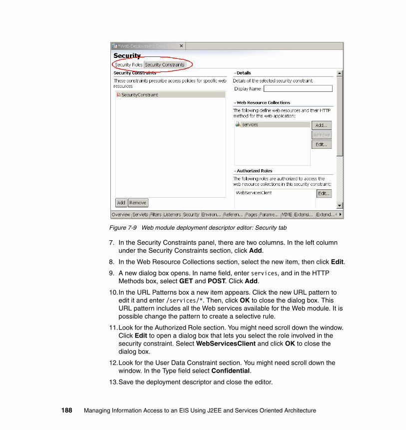
Figure 7-9 Web module deployment descriptor editor: Security tab
7. In the Security Constraints panel, there are two columns. In the left column under the Security Constraints section, click Add.
8. In the Web Resource Collections section, select the new item, then click Edit.
9. A new dialog box opens. In name field, enter services, and in the HTTP Methods box, select GET and POST. Click Add.
10.In the URL Patterns box a new item appears. Click the new URL pattern to edit it and enter /services/*. Then, click OK to close the dialog box. This URL pattern includes all the Web services available for the Web module. It is possible change the pattern to create a selective rule.
11.Look for the Authorized Role section. You might need scroll down the window. Click Edit to open a dialog box that lets you select the role involved in the security constraint. Select WebServicesClient and click OK to close the dialog box.
12.Look for the User Data Constraint section. You might need scroll down the window. In the Type field select Confidential.
13.Save the deployment descriptor and close the editor.
188 Managing Information Access to an EIS Using J2EE and Services Oriented Architecture

The previous steps defined a role which has the right to access Web services. Now, you need to define who can play the WebServicesClient role. Notice that the following configuration should be changed during deployment procedures to meet the security policy of the target environment.
1. In the J2EE hierarchy view, find the EAR file that contains the Web services module and double select it.
2. Select the Security tab (see Figure 7-10).
Figure 7-10 EAR Deployment Descriptor Editor: Security tab
3. Click Gather... to gather the security roles defined in the modules owned by the EAR project.
4. When the WebServicesClient role has appeared, select it and select All authenticated users under the WebSphere Bindings section. With this selection, all valid users in the WebSphere registry are authorized to use the Web service.
5. Save the deployment descriptor and close the editor.
Now, the Web services are secured using the HTTPS protocol, and the users are authenticated against the WebSphere registry.
7.5.3 TransactionsOne of the most important concepts in information technology is the transaction concept. Broadly speaking, the transaction concept is the basic capability of a system to execute a set of operations in an assured and safe manner.
Chapter 7. Using Web services 189

Computer science defines the essential properties of a transaction as:
� Atomicity
If a transaction is successful, then all the operations happen, If it is unsuccessful, then none of the operations happen.
� Consistency
The application performs valid state transitions at completion.
� Isolation
The effects of the operations are not shared outside the transaction until it completes successfully.
� Durability
Once a transaction successfully completes, the changes survive failure.
An extension of this concept is the distributed transaction, which applies to distributed systems. Distributed systems consist of a number of computers connected by a network. Such systems complicate the handling of failures of any of the components involved in a distributed transaction. To face this kind of issue, the two-phase commit protocol was introduced. This protocol implies that holding onto the resources for the entire duration of the transaction can reduce the concurrency in the system. This protocol is heavyweight and has many requirements, so that even in the traditional transactional environments, it is a rarely achieved target.
The network of systems that interact in an SOA can be seen as just another kind of distributed system. However, this environment is even more complex than the traditional distributed systems concept. A legacy distributed system is a hierarchical organization of systems tightly coupled, while the SOA is more like an ecosystem where the parties cooperate in a loosely coupled manner. This environment makes it difficult to propose traditional atomic transactions as part of the business-to-business relationship.
As a result of these considerations, there is not a really a necessity for atomic transactions in an SOA world. Instead, you often have to model the business interactions in an asynchronous manner. For interactions that require a status change in the target system, you should always define an undo activity. It helps to think of SOA interactions as being similar to a reservation request rather than as a committed transaction.
WS-TransactionWS-Transaction includes support for two types of transactions. It describes coordination types that are used with the extensible coordination framework as
190 Managing Information Access to an EIS Using J2EE and Services Oriented Architecture

described in WS-Coordination. Two coordination types are defined: atomic transaction and business activity.
� Atomic transactions
The protocols for atomic transactions handle activities that are short-lived. Atomic transactions are often referred to as transactions that provide a two-phase commit protocol. The transaction scope states that all work is completed in its entirety, and that the result of an activity, if successful, is that all operations are performed. If the activity is unsuccessful, then no operations have been performed. Upon successful completion of an activity the results of the activity are available to other users.
� Business activity
The protocols for business transactions handle long-lived activities. These activities differ from atomic transactions in that such activities can take much longer to complete. To minimize latency of access by other potential users of the resources used by the activity, the results of interim operations need to be released before the overall activity has completed. Thus, mechanisms for fault and compensation handling are introduced to reverse the effects of a completed business tasks.
WS-Transaction is a building block used with other specifications (for example, WS-Coordination and WS-Security) and application-specific protocols that are able to accommodate a wide variety of coordination protocols that are related to the coordination actions of distributed applications.
For more information about the published specifications that are available, see:
http://ibm.com/developerworks/library/specification/ws-tx/
WS-CoordinationWS-Coordination is a general purpose and extensible framework that provides protocols to coordinate the actions of distributed transactions. The defined framework enables an application service to create a context that is needed to propagate an activity to other services and to register for coordination protocols. The framework also enables existing transaction processing, workflow, and other systems to hide their proprietary protocols and to operate in a heterogeneous environment. It can be used with message sequencing and state machine synchronization.
For more information about the published specification that is available, see:
http://ibm.com/developerworks/library/specification/ws-tx/
Chapter 7. Using Web services 191

ConclusionsThere are no products that implement WS-Transaction as it is currently defined. Nevertheless, WebSphere Business Integration Server Foundation implements Compensation, which is the mechanism at the basis of a business activity as it is defined by the WS-Transaction specification.
At this time, we can combine the use of the compensation with a carefully designed business process to solve the almost all the business requirements of a business-to-business interaction.
In a scenario of EIS integration, the lack of a two-phase commit protocol can be an important issue. However, before you exclude a Web services solution, consider the following:
� It is possible to implement application logic that works around the lack of a two-phase commit.
� WS-Transaction will be available soon.
For further information about process choreography, see Patterns: Serial and Parallel Processes for Process Choreography and Workflow, SG24-6306.
7.5.4 ManageabilityEvery time you offer a service, you need to control it. You need the following management capabilities:
� Discover the service existence� Test the service availability� Monitor and tune performance� Audit the service usage� Modify the service configuration
Web services are not just another API. If you must entrust your business to this technology, you need a stable and proven middleware to run it. WebSphere Application Server and WebSphere Business Integration Server Foundation offer tools to address Web services manageability, including:
� The private UDDI registry, which provides a way to publish and discover information about Web services.
� The Web Services Gateway, which handles Web service invocations between Internet and intranet environments.
� The Performance Monitoring Infrastructure (PMI), which collects data from the run-time. Tivoli Performance Viewer then visualizes the data and gives hints on how to optimize the configuration.
192 Managing Information Access to an EIS Using J2EE and Services Oriented Architecture

� The Assembly Toolkit , which can graphically edit the Web services deployment descriptor (according to the JSR 109 standard). It can handle the WS-security details.
� A configuration infrastructure, which is accessible either through the WebSphere Administrative Console or through JMX technology.
7.5.5 InteroperabilityFor the key promise of WS-I to work, you need to manage standards carefully. In addition, guidance in interpretation and implementation of standards is essential to facilitate adoption of a technology. The Web Services Interoperability Organization has an important role in this area, as a standards integrator to help Web services advance in a structured and coherent manner.
Commitment from IBM in this direction includes active participation in WS-I standards development and early delivery of WS-I compliance in runtime and development products. In this redbook, we place considerable emphasis on WS-I standards and guidelines as an enabler for Web services interoperability.
Web Services Interoperability OrganizationThe Web Services Interoperability Organization (WS-I) is an open, industry consortium of about 150 companies that represent diverse industries, such as automotive, consumer packaged goods, finance, government, insurance, media, telecommunications, travel, and the computer industry. This organization is chartered to:
� Promote Web services interoperability across platforms, operating systems, and programming languages with the use of generic protocols for interoperable exchange of messages between services.
� Encourage Web services adoption.
� Accelerate Web services deployment by providing guidance, best practices, and other resources for developing interoperable Web services.
The WS-I, as a standards integrator, supports relationships with standards groups who own specifications and fosters communication and cooperation with industry consortia and other organizations.
The organization has a set of deliverables to assist in the development and deployment of Web services, including its profile of interoperable Web services that is defined in the WS-I glossary as:
A collection of requirements to support interoperability. WS-I will deliver a collection of profiles that support technical requirements and specifications to achieve interoperable Web Services.
Chapter 7. Using Web services 193

A WS-I profile includes the following deliverables:
� Profile specification
The profile specification includes a list of non-proprietary Web services specifications at certain version levels, plus a list of clarifications and restrictions on those specifications to facilitate the development of interoperable Web services.
� Use cases and usage scenarios
These requirements capture the business and technical requirements for the use of Web services. Use cases and usage scenarios reflect the classes of real-world requirements that support Web services solutions and provide a framework to demonstrate the guidelines that are described in WS-I profiles.
� Sample applications
These applications demonstrate the implementation of applications that are built from Web services usage scenarios and use cases and that conform to a given set of profiles. Implementations of the same sample application on multiple platforms, using different languages and development tools, allow WS-I to demonstrate interoperability in action and to provide readily usable resources for the Web services practitioner.
� Testing tools
These tools are used to monitor and analyze interactions with a Web service to determine whether the messages that are exchanged conform to WS-I profile guidelines.
For more information about the WS-I, refer to:
http://www.ws-i.org/
WS-I Basic Profile 1.0The WS-I has delivered its first profile of interoperable Web services called WS-I Basic Profile 1.0. The profile focuses on the core foundation technologies upon which Web services are based, including HTTP, SOAP, WSDL, UDDI, XML, and XML Schema. Basic Profile 1.0 was unanimously approved on July 22, 2003, by the organization’s board of directors and members.
The WS-I Basic Profile 1.0, Profile Specification consists of the following non-proprietary Web services specifications:
� SOAP 1.1
� WSDL 1.1
� UDDI 2.0
� XML 1.0 (Second Edition)
194 Managing Information Access to an EIS Using J2EE and Services Oriented Architecture

� XML Schema Part 1: Structures
� XML Schema Part 2: Datatypes
� RFC2246: The Transport Layer Security Protocol Version 1.0
� RFC2459: Internet X.509 Public Key Infrastructure Certificate and CRL Profile
� RFC2616: HyperText Transfer Protocol 1.1
� RFC2818: HTTP over TLS
� RFC2965: HTTP State Management Mechanism
� The Secure Sockets Layer Protocol Version 3.0
For more information about the WS-I Basic Profile see the following articles:
� WS-I Basic Profile 1.0
http://www.ibm.com/developerworks/webservices/library/ws-basicprof.html
� WS-I Usage Scenarios
http://www.ibm.com/developerworks/webservices/library/ws-iuse/
� Preview of WS-I sample application
http://www.ibm.com/developerworks/webservices/library/ws-wsisamp/
Security and interoperationAt the time that we wrote this book, the Basic Security Profile Version 1.0 was still a draft document. Thus, we cannot give a WS-I certification for the WS-Security implementations. Nevertheless, there are many test cases of interoperability between the implementation by IBM and the implementation by Microsoft.
IBM is one of three editors of the Basic Security Profile 1.0, along with Microsoft and Nortel Networks.
7.6 Further informationBecause Web services technology is fast growing and touches many fields, it is impossible to give a complete view of the technology in this redbook. This chapter discussed Web services as they relate to our purpose in this book. For a deeper understanding of Web services, this section lists some useful readings.
Note: The WS-I has recently updated the WS Basic Profile to version 1.1. The content of the document has been reorganized. However, it is equivalent to the previous version with the addition of published errata.
Chapter 7. Using Web services 195

7.6.1 Redbooks from IBMThe Web services topic is widely exposed in many publications of the IBM International Technical Support Organization. The following are summaries of those redbooks mentioned in this chapter:
� Using Web Services for Business Integration, SG24-6583
– Web services technology and standards
– Transactions
� Patterns: Service-Oriented Architecture and Web Services, SG24-6303 and Patterns: Implementing an SOA Using an Enterprise Service Bus, SG24-6346
– The SOA phenomenon: motivations, evolution, and best practices
� z/OS WebSphere Application Server V5 and J2EE 1.3 Security Handbook, SG24-6086
– Security issues related to EIS integration
– A brief explanation of the Web Services security
� IBM WebSphere V5.1 Performance, Scalability, and High Availability WebSphere Handbook Series, SG24-6198
– Scalability and high availability of the WebSphere platform as the host environment for Web services
– Performance considerations, with details, on how to enable the cache for Web services
� WebSphere Version 5.1 Application Developer 5.1.1 Web Services Handbook, SG24-6891
– Introduction to WSDL
– Implementing Enterprise Web Services (JSR 109)
– Web services invocation framework
– Web Services Gateway
� WebSphere Version 5 Application Development Handbook, SG24-6993 describes:
– Web services evolution
– Service-oriented architecture
– Web services approach for a SOA
� WebSphere Business Integration Server Foundation V5.1, SG24-6318
– Describes this product and its implementation of the BPEL engine
196 Managing Information Access to an EIS Using J2EE and Services Oriented Architecture

� Patterns: Serial and Parallel Processes for Process Choreography and Workflow, SG24-6306
– Describes the flexibility of the BPEL language and implementation
� Using BPEL Processes in WebSphere Business Integration Server Foundation Business Process Integration and Supply Chain Solutions, SG24-6324
– Contains some clear explanations of WebSphere Studio Application Developer Integration Edition V5.1
� Exploring WebSphere Studio Application Developer Integration Edition V5, SG24-6200
– An extensive guide on how the product helps development in a service oriented manner
� IBM WebSphere V5.0 Security, WebSphere Handbook Series, SG24-6573
– Describes security issues in detail
7.6.2 Resource on the WebYou can find the following resources on the Web:
� For a discussion on the fundamental characteristics of a Web services architecture and the benefits of this approach
http://www-106.ibm.com/developerworks/webservices/library/w-ovr/
� For a collection of white papers on Web services and SOA
http://www-306.ibm.com/software/solutions/webservices/resources.html
� For a discussion on the best practices for performance of the Web services
http://www-106.ibm.com/developerworks/library/ws-best9/
� For a discussion of the benefits of Web services and SOA, see ROI - The Costs and Benefits of Web Services and Service Oriented Architecture at:
http://roadmap.cbdiforum.com/reports/roi/
� For information about the SOAP cache see WebSphere Dynamic Cache: Improving J2EE application performance at:
http://www.research.ibm.com/journal/sj/432/bakalova.html
Chapter 7. Using Web services 197

198 Managing Information Access to an EIS Using J2EE and Services Oriented Architecture

Chapter 8. Integration using WebSphere Business Integration Adapters
This chapter describes how to integrate an EIS system using WebSphere Business Integration Adapters. In particular, it focuses on how to use the JDBC adapter to interact with an EIS running on WebSphere Business Integration Server Foundation.
8
© Copyright IBM Corp. 2005. All rights reserved. 199
8.1 WebSphere Business Integration Adapters overviewIBM WebSphere Business Integration Adapters provide for integration with an enterprise information system (EIS). In today’s world, where enterprises have disparate systems that need to be integrated, the WebSphere Business Integration Adapter suite provides access to information in a heterogeneous environment.
The adapter framework provides a common runtime and API that are used to develop and run the adapters. The adapters are configurable at design time and are metadata driven at runtime, allowing an organization to be responsive and flexible by incorporating new integration processes with very little development.
The WebSphere Business Integration Adapters allow for data exchange and business process integration through the use of integration brokers or integration processes. The integration brokers, such as IBM WebSphere InterChange Server and IBM WebSphere Business Integration Message Broker, provide integration using a hub-and-spoke approach for the adapters, with collaboration and message flows that are available for managing the data integration scenarios. The integration processes are available through the use of Business Process Choreographer and the Business Process Container in the WebSphere Business Integration Server Foundation. The integration processes are created in Business Process Choreographer which then uses the adapters to integrate different business processes with an enterprise.
The WebSphere Business Integration Adapters have a set of features that allow them to provide an on demand e-business with the ability to adapt, scale processes, and rapidly deploy the solution. The adapters are:
� Configurable
The adapters are configurable at design time to connect to different EIS. The adapters can be quickly and easily configured for different integration brokers and quality of service.
� Metadata driven
The adapters are metadata driven, allowing many different integration patterns without changing code or needing any development effort. The presence of application-specific metadata allows the adapter to integrate with different components and services within an EIS without the need to recode or do new development. Using the metadata, the adapter can do context-based processing by prioritizing requests and providing optional quality of service, such as support for long-running processes in conjunction with the EIS.
200 Managing Information Access to an EIS Using J2EE and Services Oriented Architecture
� Bi-directional
The adapters have the ability to both send information to the EIS and to retrieve events from the EIS. The process of sending information to the EIS is referred to as request processing. Processing a request from an integration broker or a client service to perform an operation in the EIS. Event notification is the retrieval of changes and updates in an EIS component and propagating these changes to an integration broker or client service.
� Multi-threaded request processing
Typically, an adapter is multi-threaded during request processing. Thus, the adapter can handle multiple simultaneous requests to perform different operations on the EIS, allowing for scalability and better performance.
There are two distinct type of adapters:
� Application adapters� Technology adapters
These two types of adapters allow integration with legacy applications, mainframe systems, and different technologies. The application adapters provide for integration through the use of the EIS-specific API. These EIS include SAP, PeopleSoft, i2, JD Edwards, Siebel, and Oracle Applications. The technology adapters provide integration using standard technologies such as JDBC, JMS, and Web services. The technology adapters include JDBC for relational database, JText for text files, and Web services for service integration to WebSphere Business Integration.
For a complete listing of available adapters, see:
http://www.ibm.com/software/integration/wbiadapters
The adapters typically include an object discovery component that allows for metadata introspection and business object creation. Metadata introspection is the process of retrieving information about the data, program objects, or processes in an EIS.
8.2 Adapter-based integrationIntegration using WebSphere Business Integration Adapters can be accomplished by using an integration broker or a client service to initiate requests or to accept events from the adapter. Through the use of the adapter framework, the broker or client can integrate with different enterprise applications using multiple WebSphere Business Integration Adapters.
Chapter 8. Integration using WebSphere Business Integration Adapters 201

Business objects are developed, and the adapter is configured to connect to a specific instance of the EIS. The adapter is then deployed, and its service and operations are exposed within an integration broker or client, which then makes calls on the underlying EIS.
8.2.1 Adapter request processing interaction patternWith request processing, the integration broker and clients send requests that use a business object to the adapter through the adapter framework. The adapter parses the incoming business object and makes the request specified on the EIS using application-specific metadata and the business object content. The adapter then returns the results, if any, of the call. WebSphere Business Integration Adapters typically perform create, update, delete, and retrieve functions using the verb attribute within a business object. Adapters can also execute business processes in an underlying EIS (for example, to calculate an order schedule).
Within the interaction pattern for request processing within WebSphere Business Integration Server Foundation, the BPEL process makes a request through JMS on the adapter. Figure 8-1 shows the components view for this interaction style.
Figure 8-1 Request interaction pattern components view
The adapter can process requests from a business process in two ways:
� The BPEL process can send a synchronous request to the adapter, where the process sends a request to the adapter and waits for a response. This process is also referred to as the Hub Request interaction pattern, where the hub in this case is the executing business process. The names of the port types in the adapter service WSDL files reflect this pattern in their naming convention.
� The BPEL process can also invoke an asynchronous request on the adapter, where the process sends a request to the adapter without waiting for a response. This process is referred to as the Hub One Way interaction pattern.
The WebSphere Business Integration Adapter is created as a WebSphere Application Server project within the WebSphere Business Integration tool set and is configured to access the EIS with the appropriate business objects. The
WebSphere Business Integration Server Foundation
JMS
WBI Adapter
Adapter FrameworkMQ
EISBPELProcess
202 Managing Information Access to an EIS Using J2EE and Services Oriented Architecture

project is then exported with a JMS binding service, which exposes the operations and business objects available for the adapter. The adapter service is then incorporated into a BPEL process, which makes WSIF calls to the adapter through the configured WebSphere MQ queue connection factory and queues.
The adapter retrieves the request, processes the business object by parsing and analyzing application specific metadata, then executes the operation on the underlying EIS. The result is then parsed and transformed into a business object and sent to the business process.
8.2.2 Adapter event notification interaction patternWith event notification, the adapter sends a messages to the integration broker or client, signifying that a data change or process activity has happened in the EIS.
There are several different mechanisms for event propagation from an EIS to the integration broker. The mechanism relies on the capabilities of the EIS. Mechanisms for event propagation include a registering for events, a service callback system, polling an event data store, and using triggering scripts.
Most EIS vendors do not provide any event notification mechanism. The WebSphere Business Integration Adapters need to develop or include an appropriate notifying device to capture and express these events.
Adapters typically use an event store located within the EIS. This event store is populated using a triggering mechanism that is specific to the EIS component. The events are then retrieved from the event store and propagated to the integration broker or client.
The interaction pattern for event notification within WebSphere Business Integration Server Foundation involves the adapter invoking a BPEL service after an event has happened in the EIS. Figure 8-2 on page 204 shows the components involved in an event notification interaction.
Chapter 8. Integration using WebSphere Business Integration Adapters 203

Figure 8-2 Event notification Interaction components view
The adapter can send event notifications in two ways to the business process.
� The adapter can send a synchronous event delivery, where the adapter sends a message to the processes and expects a response. This process is also referred to as the Agent Request interaction pattern. The names of the port types in the adapter service WSDL files reflect this pattern naming convention.
� The adapter can also do an asynchronous event delivery, where the adapter sends a message to the business process and does not wait for a response. This process is referred to as the Agent Delivery interaction pattern.
In both scenarios an MDB is used to listen for events on the queue configured for event delivery. The adapter polls for events in the EIS then retrieves the events and places them on the appropriate delivery queue. The event messages are retrieved from the queues and sent to the business process.
8.2.3 Adapter object discoveryThe adapters object discovery agent (ODA) introspects metadata information from the EIS by either analyzing the application’s data store, business processes, and components or by using a metadata introspection API.
The adapter ODA is written using the object discovery agent development kit (ODK). It provides a set of APIs that allows for tight integration with the WebSphere Business Integration Business Object Designer Tool. The ODK also provides guidance to developers on how to develop an ODA.
The ODA generally creates ready-to-use business objects, with application-specific metadata already in place. There is little to no customization required on the developers part at design time.
WebSphere Business Integration Server Foundation
BPELProcess
Calls
Listens
WBI Adapter
Adapter FrameworkMQMessage Driven Bean
EIS
204 Managing Information Access to an EIS Using J2EE and Services Oriented Architecture

In conjunction with the Business Object Designer, the ODA can allow batch business object creation and special filtering, providing for an easier development path to integrate to the underlying EIS.
8.3 Adapter-based integration building blockThe WebSphere Business Integration Adapter integration building block involves the adapter exposed as a service in the Business Process Container of WebSphere Business Integration Server Foundation. Then a request processing call is exposed as a service to the Stock Analysis business process.
8.3.1 Scenario problem statementThe buy shares scenario requires stock information, which is stored in an external EIS. The EIS has the information that is required. The WebSphere Business Integration Adapter for JDBC provides for the retrieval of this information from the database of the EIS.
8.3.2 System architectureThe WebSphere Business Integration Adapter for JDBC resides on the machine where the database repository is located. The system analysis business processes makes a request for stock information through the system process. The context information that is passed within the request allows the system process to route the message to the appropriate provider. The stock analysis business process and the system process are both running in WebSphere Business Integration Server Foundation on a separate machine and making calls on the adapter through its exposed service process.
See Chapter 3, “Scenario overview and design” on page 65 for the system design view.
8.3.3 Components of the building blockThe components of the adapter integration building block include:
� WebSphere Business Integration Adapter Framework� The BPEL process, which wraps the adapter service� The adapter service, which exposes the adapters stock retrieval operation� The business object, which is used to represent the stock data� The critical business process, which uses this service.
Chapter 8. Integration using WebSphere Business Integration Adapters 205
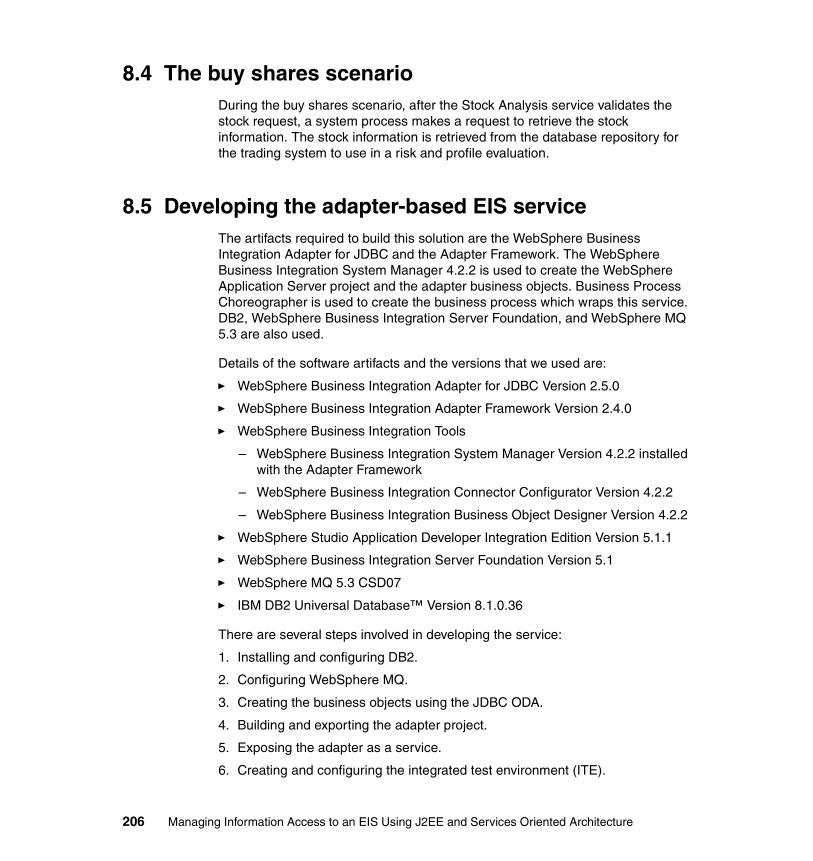
8.4 The buy shares scenarioDuring the buy shares scenario, after the Stock Analysis service validates the stock request, a system process makes a request to retrieve the stock information. The stock information is retrieved from the database repository for the trading system to use in a risk and profile evaluation.
8.5 Developing the adapter-based EIS serviceThe artifacts required to build this solution are the WebSphere Business Integration Adapter for JDBC and the Adapter Framework. The WebSphere Business Integration System Manager 4.2.2 is used to create the WebSphere Application Server project and the adapter business objects. Business Process Choreographer is used to create the business process which wraps this service. DB2, WebSphere Business Integration Server Foundation, and WebSphere MQ 5.3 are also used.
Details of the software artifacts and the versions that we used are:
� WebSphere Business Integration Adapter for JDBC Version 2.5.0
� WebSphere Business Integration Adapter Framework Version 2.4.0
� WebSphere Business Integration Tools
– WebSphere Business Integration System Manager Version 4.2.2 installed with the Adapter Framework
– WebSphere Business Integration Connector Configurator Version 4.2.2
– WebSphere Business Integration Business Object Designer Version 4.2.2
� WebSphere Studio Application Developer Integration Edition Version 5.1.1
� WebSphere Business Integration Server Foundation Version 5.1
� WebSphere MQ 5.3 CSD07
� IBM DB2 Universal Database™ Version 8.1.0.36
There are several steps involved in developing the service:
1. Installing and configuring DB2.
2. Configuring WebSphere MQ.
3. Creating the business objects using the JDBC ODA.
4. Building and exporting the adapter project.
5. Exposing the adapter as a service.
6. Creating and configuring the integrated test environment (ITE).
206 Managing Information Access to an EIS Using J2EE and Services Oriented Architecture

The next sections explain how to create the service. In these sections, we refer to the JDBC adapter guide found at:
http://publib.boulder.ibm.com/infocenter/wbihelp/index.jsp
8.5.1 Installing and configuring the DB2 softwareThe database that we used was IBM DB2 UDB Version 8.1.0.36.
Table 8-1 shows the structure of the stock quote analysis data. The database name is STOCKSYS, and the table is name StockInfo.
Table 8-1 Structure of the stock quote analysis data
8.5.2 Configuring WebSphere MQ queue manager and queuesYou need to create the queue manager, queues, and channels that the JDBC Adapter uses. You also need to create the WebSphere MQ JMS provider Queue Connection Factory.
1. Create a queue manager called ITF using the WebSphere MQ Explorer.
2. Expand the Advanced → Channels folders. Right-click Channels and choose New → Server Connection Channel. Name the channel and click OK.
3. Open a command line and execute the following command using the text file shown in Example 8-1 on page 208.
runmqsc ITF < configure_mq.txt
Column Name Type
Symbol VARCHAR(4)-Not Null and Primary Key
Value VARCHAR(10)
Trend INTEGER- Default 0, valid values -1,0,1
Change VARCHAR(10)
High VARCHAR(10)
Low VARCHAR(10)
Company VARCHAR(60)
Chapter 8. Integration using WebSphere Business Integration Adapters 207
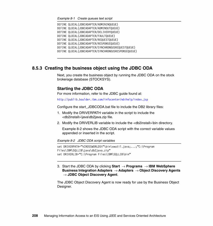
Example 8-1 Create queues text script
DEFINE QLOCAL(JDBCADAPTER/ADMININQUEUE)DEFINE QLOCAL(JDBCADAPTER/ADMINOUTQUEUE)DEFINE QLOCAL(JDBCADAPTER/DELIVERYQUEUE)DEFINE QLOCAL(JDBCADAPTER/FAULTQUEUE)DEFINE QLOCAL(JDBCADAPTER/REQUESTQUEUE)DEFINE QLOCAL(JDBCADAPTER/RESPONSEQUEUE)DEFINE QLOCAL(JDBCADAPTER/SYNCHRONOUSREQUESTQUEUE)DEFINE QLOCAL(JDBCADAPTER/SYNCHRONOUSRESPONSEQUEUE)
8.5.3 Creating the business object using the JDBC ODANext, you create the business object by running the JDBC ODA on the stock brokerage database (STOCKSYS).
Starting the JDBC ODAFor more information, refer to the JDBC guide found at:
http://publib.boulder.ibm.com/infocenter/wbihelp/index.jsp
Configure the start_JDBCODA.bat file to include the DB2 library files:
1. Modify the DRIVERPATH variable in the script to include the <db2install>\java\db2java.zip file.
2. Modify the DRIVERLIB variable to include the <db2install>\bin directory.
Example 8-2 shows the JDBC ODA script with the correct variable values appended or inserted in the script.
Example 8-2 JDBC ODA script variables
set DRIVERPATH=”%CROSSWORLDS%”\bin\xwutil.java;...;”C:\Program Files\IBM\SQLLIB\java\db2java.zip”set DRIVERLIB=”C:\Program Files\IBM\SQLLIB\bin”
3. Start the JDBC ODA by clicking Start → Programs → IBM WebSphere Business Integration Adapters → Adapters → Object Discovery Agents → JDBC Object Discovery Agent.
The JDBC Object Discovery Agent is now ready for use by the Business Object Designer.
208 Managing Information Access to an EIS Using J2EE and Services Oriented Architecture
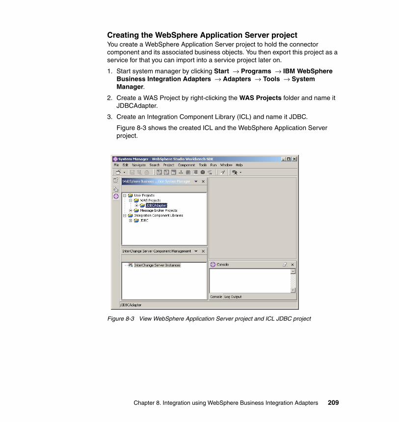
Creating the WebSphere Application Server projectYou create a WebSphere Application Server project to hold the connector component and its associated business objects. You then export this project as a service for that you can import into a service project later on.
1. Start system manager by clicking Start → Programs → IBM WebSphere Business Integration Adapters → Adapters → Tools → System Manager.
2. Create a WAS Project by right-clicking the WAS Projects folder and name it JDBCAdapter.
3. Create an Integration Component Library (ICL) and name it JDBC.
Figure 8-3 shows the created ICL and the WebSphere Application Server project.
Figure 8-3 View WebSphere Application Server project and ICL JDBC project
Chapter 8. Integration using WebSphere Business Integration Adapters 209

4. Right-click the Business Objects folder and click Create New Business Object.
The WebSphere Business Integration Business Object Designer tool launches. You use this tool to create the business object to be used, which represents the StockInfo table to the adapter and its clients.
5. Click File-New Using ODA... to create the business object using the JDBC ODA.
6. On the Business Object Wizard Step 1 page, click Find Agents. After the agent appears, you can click Cancel or wait for it to finish.
7. Select JDBCODA agent from the located agents list, then click Next. Figure 8-4 shows the designer with the agent found on our test machine and the details of the port on which it is running.
Figure 8-4 Business Object Wizard- Find Agent
210 Managing Information Access to an EIS Using J2EE and Services Oriented Architecture

8. On the Business Object Wizard Step 2-Configure Agent, enter the database username and password, database URL, and database driver in the configuration property values. Figure 8-5 shows example properties.
Figure 8-5 Business Object Wizard -Configure Agent
9. On the Business Object Wizard Step 3-Select Source, expand the SCHEMA that you used to create the STOCKINFO table then expand the Tables and select the STOCKINFO table (Figure 8-6 on page 212).
Note: Firewalls sometimes cause problems when connecting to the ODA agent . You can disable your firewall temporarily to allow the business object designer to find and connect to the running ODA. Sometimes on Windows systems, the default firewall is installed and running, so check that also.
Chapter 8. Integration using WebSphere Business Integration Adapters 211

Figure 8-6 Selecting STOCKINFO table
These steps introspected the database schema and the tables in that schema. You are now ready to retrieve the table information and to generate the business object with its associated application specific metadata.
10.Click Next to accept the defaults.
11.On the Business Object Properties table change Add Stored Procedures to NO, and then click OK.
12.Save the Business Object to the JDBC ICL project that was created in system manager.
212 Managing Information Access to an EIS Using J2EE and Services Oriented Architecture

Figure 8-7 is a view of the business object created by the ODA.
Figure 8-7 View of STOCKINFO business object
Creating the JDBC connector componentNext, you create the JDBC Adapter connector component, which represents the adapter, and you configure the adapter properties.
1. Right-click the Connectors folder in the JDBC Component folder. Click New Connector.
2. The Connector Configurator and the New Connector dialog box opens. Select JDBCConnectorTemplate from the list of template names.
3. Name the Connector JDBCAdapter.
4. Select WAS as the Integration Broker.
Chapter 8. Integration using WebSphere Business Integration Adapters 213
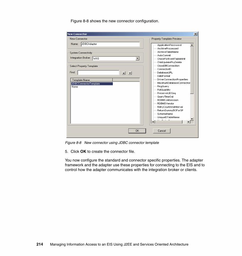
Figure 8-8 shows the new connector configuration.
Figure 8-8 New connector using JDBC connector template
5. Click OK to create the connector file.
You now configure the standard and connector specific properties. The adapter framework and the adapter use these properties for connecting to the EIS and to control how the adapter communicates with the integration broker or clients.
214 Managing Information Access to an EIS Using J2EE and Services Oriented Architecture

Figure 8-9 shows the connector specific properties that you need to set for the JDBC adapter for the adapter to connect to the underlying database.
Figure 8-9 JDBC adapter connector configuration
For more information about connector properties and their default behavior, see the JDBC adapter guide at:
http://www.ibm.com/software/integration/adapters
To configure the standard and connector specific properties:
1. On the Standard Properties tab, enter the following:
– For BrokerType, choose WAS from the drop-down list.
– jms.MessageBrokerName, which is your WebSphere MQ queue manager. If your queue manager is remote, then you need a URL in the form queuemanager:channel:server:listenerport.
Chapter 8. Integration using WebSphere Business Integration Adapters 215

– jms.UserName, if the WebSphere MQ provider is remote, you need to enter the user name that has access to the queue manager.
– jms.Password, if the WebSphere MQ provider is remote, you need to enter the password for the user that has access to the queue manager.
– MessageFileName, which is JDBCConnector.txt.
2. On the Connector Specific tab, enter the following:
– ApplicationUserName, database user
– ApplicationPassword, database password
– CheckForEventTableInInit, false
– DatabaseURL, jdbc:db2:stocksys
– JDBCDriverClass, COM.ibm.db2.jdbc.app.DB2Driver
– RDBMSVendor, DB2
– EventTableName, null
3. On the Supported Business Objects tab, add the STOCKINFO business object.
4. Save the configuration to the project by pressing Ctrl+S.
5. Save a copy of the configuration to a file, to be used to run the JDBC Adapter later on, by pressing Ctrl+Alt+F. Save the file to the filename C:\ITF\JDBCAdapter.cfg.
Configure the JDBC adapter start scriptNow, you configure the start script to find the driver that is required to connect to the DB2 database.
1. Right-click the start_JDBC.bat file found in the default JDBC directory, C:\IBM\WebSphere\connectors\JDBC.
2. Click Edit to edit the file.
3. Modify the JDBCDRIVERPATH variable in the script to include the <db2install>\java\db2java.zip file.
4. Add a new variable JDBCDRIVERLIB to include the <db2install>\bin directory.
5. Set the JDBCDRIVERLIB as the last value in the -Djava.library.path JVM argument at the end of the script.
216 Managing Information Access to an EIS Using J2EE and Services Oriented Architecture
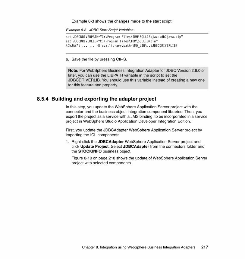
Example 8-3 shows the changes made to the start script.
Example 8-3 JDBC Start Script Variables
set JDBCDRIVERPATH=”C:\Program Files\IBM\SQLLIB\java\db2java.zip”set JDBCDRIVERLIB=”C:\Program Files\IBM\SQLLIB\bin”%CWJAVA% ... ... -Djava.library.path=%MQ_LIB%..%JDBCDRIVERLIB%
6. Save the file by pressing Ctl+S.
8.5.4 Building and exporting the adapter projectIn this step, you update the WebSphere Application Server project with the connector and the business object integration component libraries. Then, you export the project as a service with a JMS binding, to be incorporated in a service project in WebSphere Studio Application Developer Integration Edition.
First, you update the JDBCAdapter WebSphere Application Server project by importing the ICL components.
1. Right-click the JDBCAdapter WebSphere Application Server project and click Update Project. Select JDBCAdapter from the connectors folder and the STOCKINFO business object.
Figure 8-10 on page 218 shows the update of WebSphere Application Server project with selected components.
Note: For WebSphere Business Integration Adapter for JDBC Version 2.6.0 or later, you can use the LIBPATH variable in the script to set the JDBCDRIVERLIB. You should use this variable instead of creating a new one for this feature and property.
Chapter 8. Integration using WebSphere Business Integration Adapters 217

Figure 8-10 Update application server project using ICL project
2. Click Finish to update the project.
The WebSphere Application Server project now has all the business objects and connectors included.
Figure 8-11 on page 219 is a view of the system manager after this step. The WebSphere Application Server project now shows the business objects and the connector configuration.
218 Managing Information Access to an EIS Using J2EE and Services Oriented Architecture

Figure 8-11 The JDBCAdapter WebSphere Application Server project updated
3. You now deploy the JDBCAdapter project as a WebSphere Application Server project to create the service WSDL and bindings and to define the business object in a XML schema document (XSD).
Chapter 8. Integration using WebSphere Business Integration Adapters 219

Figure 8-12 shows the deploy WebSphere Application Server project wizard.
Figure 8-12 Deploy JDBCAdapter WebSphere Application Server project
4. Right-click the JDBCAdapter folder in the WebSphere Application Server project. Click Deploy WAS Project. Ensure that the JDBCAdapter connector and the STOCKINFO business object are shown. Click Next.
5. Select Export to a Directory. Choose a folder to place the project in by clicking the Browse button. Click Finish.
Note: The connector configuration shows only supported business objects. If no business objects appear or if not all the business objects appear, you need to add them. You can open the configuration, using the WebSphere Business Integration Connector Configurator, by double-clicking the JDBC adapter in the connectors folder. Then navigate to the supported business objects tab and add the business object. Only business objects saved in the ICL project will appear.
220 Managing Information Access to an EIS Using J2EE and Services Oriented Architecture
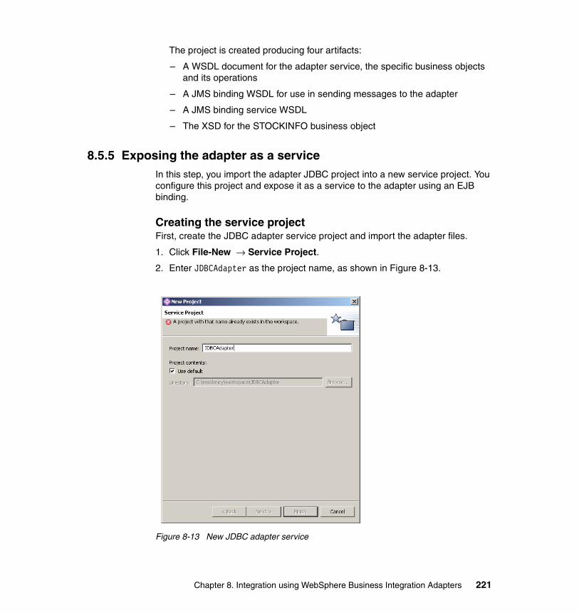
The project is created producing four artifacts:
– A WSDL document for the adapter service, the specific business objects and its operations
– A JMS binding WSDL for use in sending messages to the adapter
– A JMS binding service WSDL
– The XSD for the STOCKINFO business object
8.5.5 Exposing the adapter as a serviceIn this step, you import the adapter JDBC project into a new service project. You configure this project and expose it as a service to the adapter using an EJB binding.
Creating the service projectFirst, create the JDBC adapter service project and import the adapter files.
1. Click File-New → Service Project.
2. Enter JDBCAdapter as the project name, as shown in Figure 8-13.
Figure 8-13 New JDBC adapter service
Chapter 8. Integration using WebSphere Business Integration Adapters 221
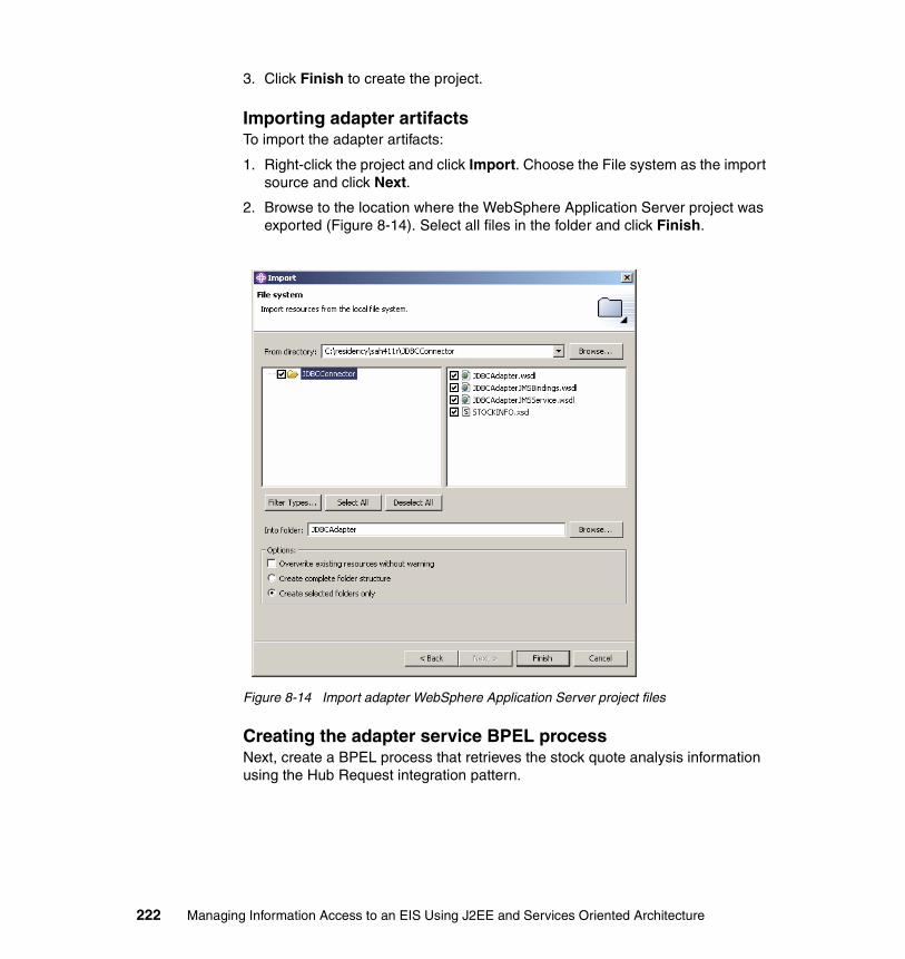
3. Click Finish to create the project.
Importing adapter artifactsTo import the adapter artifacts:
1. Right-click the project and click Import. Choose the File system as the import source and click Next.
2. Browse to the location where the WebSphere Application Server project was exported (Figure 8-14). Select all files in the folder and click Finish.
Figure 8-14 Import adapter WebSphere Application Server project files
Creating the adapter service BPEL processNext, create a BPEL process that retrieves the stock quote analysis information using the Hub Request integration pattern.
222 Managing Information Access to an EIS Using J2EE and Services Oriented Architecture

Creating a new BPEL processCreate the BPEL process which represents the stock information adapter service:
1. Right-click the JDBCAdapter service project. Click New → Business process. Figure 8-15 shows the new business process wizard.
Figure 8-15 New JDBC Adapter BPEL Process
2. Enter the package name (com.itso.wbia.jdbc) and file name (StockQuoteInfo).
3. Click Finish.
Wrapping the JMS service in an EJB serviceThe scenario requires that the request be synchronous and that the results be returned promptly. We use a microflow for this process. The adapter service was exported as JMS, which simulates a synchronous implementation by requiring a send message on the request queue and waiting on a reply on the response queue. We wrapped this JMS service in an EJB service to enable the microflow to execute in a single transaction.
Chapter 8. Integration using WebSphere Business Integration Adapters 223

First, you generate the deploy code with an EJB binding.
1. Right-click the JDBCAdapterJMSService.wsdl file found in the JDBCAdapter service project. Click Enterprise Services → Generate Deploy Code (Figure 8-16).
Figure 8-16 EJB service generate deploy code
2. Choose STOCKINFOHubRequestBindingPort as the Port Name for the Hub Request integration pattern, as shown in Figure 8-16.
You create a new port and binding using an EJB binding type to deploy the service using a session bean.
3. Click Next to go to the Inbound Services Files page.
224 Managing Information Access to an EIS Using J2EE and Services Oriented Architecture

4. Enter the package name com.itso.wbia.jdbc for the EJB project. Click Finish.
Customizing the BPEL processOpen the StockQuoteInfo.bpel file by double-clicking it. Then, follow the steps in the sections that follow.
Adding input and output variables for the JDBC AdapterNext, you add the input and output variables to be used when sending the request to the adapter.
1. Click the plus sign on the Variables box in the editor to add a variable (Figure 8-17). Name the variable QuoteInput.
Figure 8-17 QuoteInput variable
2. Repeat the previous step and add a variable called QuoteOutput (Figure 8-18 on page 226).
Chapter 8. Integration using WebSphere Business Integration Adapters 225

Figure 8-18 QuoteOutput variable
3. Select QuoteInput in the variables box. In the Message tab, we use the JDBCConnector.wsdl file to map it to the STOCK INFO Request message type.
4. Select Message, and then click Browse. Navigate to the JDBC Adapter project and select the JDBCAdapter.wsdl file. Then select STOCK INFO Request from the drop-down list.
5. Select QuoteOutput in the variables box. In the Message tab, we use the JDBCConnector.wsdl file to map it to the STOCKINFOResponse message type.
6. Select Message, then click Browse. Navigate to the JDBCAdapter project and select the JDBCAdapter.wsdl file. Then select STOCKINFOResponse from the drop-down list. The result is shown in Figure 8-18.
7. Press Ctrl+S to save the BPEL process.
Creating the data transformation snippet for InputVariableYou need to create a Java Snippet activity by clicking on the Java snippet icon and then clicking on the StockInfo Flow canvas, just between the Receive and Reply activities.
1. Enter Assign StockInfo as the Display Name. (The name will be automatically set without the spaces.) Use the transaction links to have the Receive flow to the Assign StockInfo then to the Reply.
226 Managing Information Access to an EIS Using J2EE and Services Oriented Architecture

2. Click Implementation, and on the implementation tab, enter the code shown in Example 8-4.
Example 8-4 Data transformation from input variable
STOCKINFORequestMessage requestMessage = getQuoteInput();STOCKINFOElement infoElement = new STOCKINFOElement();infoElement.setSYMBOL(“IBM”);infoElement.setVerb(“Retrieve”);requestMessage.setBodyPart(infoElement);
3. Right-click in the code tab, then select Source → Organize Imports to resolve the types.
This is where you would set the values coming from the InputVariable into the QuoteInput variable. For now, to get the test going, you can enter literals.
Creating the invoke activity for adapter callIn this step, you create the invoke activity which makes the call on the JDBC adapter service:
1. Create an invoke activity by clicking the Invoke icon and then clicking the StockInfo Flow canvas.
2. Enter Invoke JDBC Adapter as the Display Name. (The name will be automatically set without the spaces.)
3. Use the transition links to set the Invoke between the Assign StockInfo and Reply activities.
Creating the partner link for the invoke activityNext, you create the partner link for the EJB Service that you created earlier:
1. Change to the business integration perspective.
2. Select the JDBCAdapterEJB project. Expand the project until you reach the ejbModule and the package com.itso.wbia.jdbc.
3. Drag the STOCKINFOHubRequestEJBService.wsdl file over to the partner link box on the BPEL canvas. Figure 8-19 on page 228 shows the selection dialog for the Hub Request service that appears after you drop the WSDL file on the canvas.
Chapter 8. Integration using WebSphere Business Integration Adapters 227

Figure 8-19 STOCKINFOHubRequest Service Selection
4. Click OK to accept the service, port, and port type for the STOCKINFOHubRequest. This is a synchronous request on the adapter. The other port types offer the other interaction patterns or styles that are available with the adapter.
5. Set the partner link for the invoke activity. Select the activity. Then, click the partner link icon and drag it to the STOCKINFOHubRequest. Figure 8-20 shows the results.
Figure 8-20 Set Adapter Invocation ParnerLink
228 Managing Information Access to an EIS Using J2EE and Services Oriented Architecture

Setting operation and variables for the invoke activityNow, you set the operation (STOCKINFORetrieve) to invoke and create the variable to hold the result:
1. Select the Implementation tab for the Invoke JDBC Adapter activity.
Figure 8-21 Invoke JDBC Adapter Implementation view
2. Verify that the operation is STOCKINFOHubRequest and set the operation to STOCKINFORetrieve. Set the Request variable to QuoteInput and the Response variable to QuoteOutput as shown in Figure 8-21.
3. Press Ctl+S to save the flow.
Creating data transformation snippet for the OutputVariableNow, you create a Java snippet to do the data transformation for the OutputVariable to provide the result that is returned to the caller of this service:
1. Create a Java Snippet activity by clicking the Java Snippet icon and then clicking the StockInfo Flow canvas.
2. Enter Set StockQuoteInfo as the display name. (The name will be automatically set without the spaces.)
3. Use the transaction links to have Java Snippet called between the Invoke JDBC Adapter and Reply activities.
Chapter 8. Integration using WebSphere Business Integration Adapters 229

4. Click Implementation, and on the implementation tab, enter the code shown in Example 8-5:
Example 8-5 Data Transformation for Output Variable
STOCKINFOResponseMessage responseMessage = getQuoteOutput();STOCKINFOElement infoElement = responseMessage.getReturnBodyPart();//Printing results returned from adapterSystem.out.println(“Company: “ + infoElement.getCOMPANY());System.out.println(“Stock Price: “ + infoElement.getVALUE());System.out.println(“Symbol: “ + infoElement.getSYMBOL());System.out.println(“Change: “ + infoElement.getCHANGE());int trend = infoElement.getTREND();String move = “Flat”;if(trend == -1) {move = “Down”;}else if(trend == 1) {move = “Up”;}System.out.println(“Trend: “ + move);//Set Results into Output Variable
5. Right-click in the code tab, then select Source → Organize Imports to resolve the types to set the values that are coming from the QuoteOutput to the OutputVariable variable. For now, you print the results.
6. Press Ctrl+S to save the BPEL process.
Generating and deploying StockQuoteInfo serviceNext, you generate the deploy code for the StockQuoteInfo service with an EJB binding to expose the service through a session bean:
1. Right-click the StockQuoteInfo.bpel file and choose Enterprise Services → Generate BPEL Deploy Code.
2. Select ProcessPortType and confirm that the EJB binding is selected as shown in Figure 8-22 on page 231. Click OK to generate the code.
230 Managing Information Access to an EIS Using J2EE and Services Oriented Architecture

Figure 8-22 Generate Deploy code for StockQuoteInfo service
Configuring StockInfo service session bean JNDI bindingsYou configure the JNDI name for the STOCKINfoHubRequest session bean. You also configure the JNDI bindings for the WebSphere MQ connection factory and queue that are used by the service.
1. Switch to the J2EE perspective.
2. Double-click the EJB deployment descriptor in the JDBCAdapterEJB project.
3. Select the References tab.
4. Expand the StockINFOHubRequestService and select the ResourceRef item. Enter wbia/ibm/com/JDBCAdapterQCF as the JNDI name in the WebSphere Bindings section as shown in Figure 8-23 on page 232.
Chapter 8. Integration using WebSphere Business Integration Adapters 231
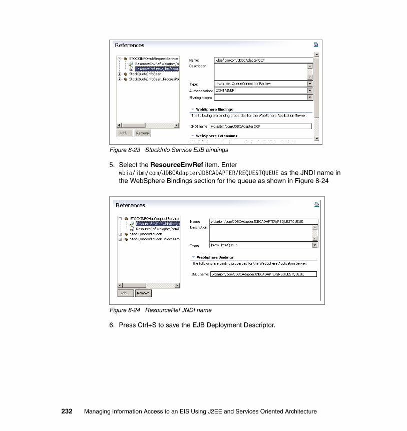
Figure 8-23 StockInfo Service EJB bindings
5. Select the ResourceEnvRef item. Enter wbia/ibm/com/JDBCAdapterJDBCADAPTER/REQUESTQUEUE as the JNDI name in the WebSphere Bindings section for the queue as shown in Figure 8-24
Figure 8-24 ResourceRef JNDI name
6. Press Ctrl+S to save the EJB Deployment Descriptor.
232 Managing Information Access to an EIS Using J2EE and Services Oriented Architecture
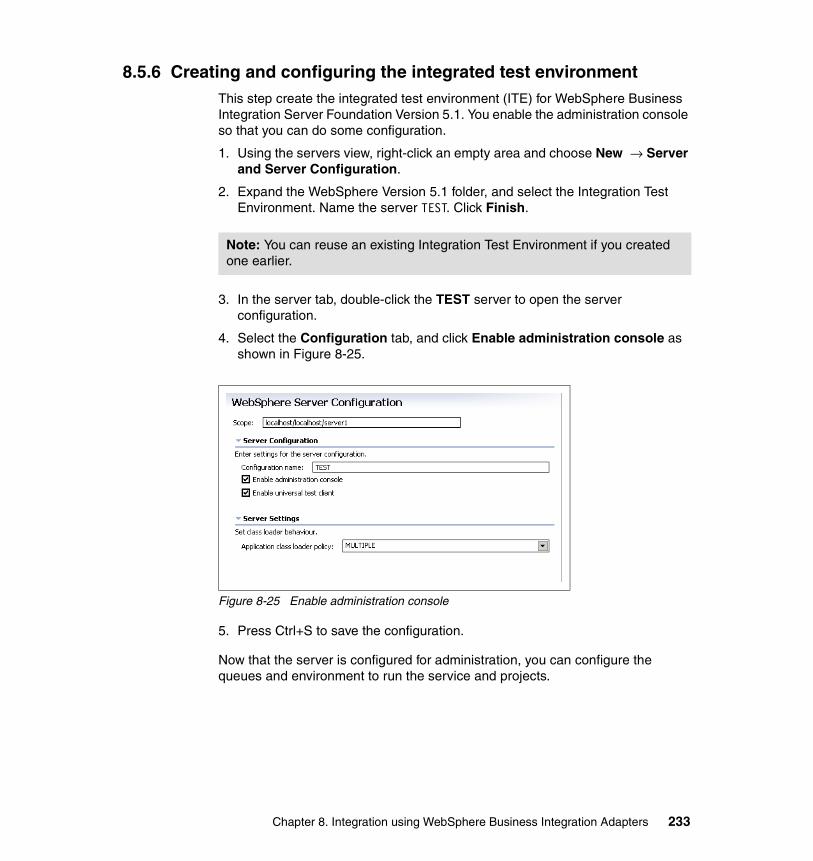
8.5.6 Creating and configuring the integrated test environmentThis step create the integrated test environment (ITE) for WebSphere Business Integration Server Foundation Version 5.1. You enable the administration console so that you can do some configuration.
1. Using the servers view, right-click an empty area and choose New → Server and Server Configuration.
2. Expand the WebSphere Version 5.1 folder, and select the Integration Test Environment. Name the server TEST. Click Finish.
3. In the server tab, double-click the TEST server to open the server configuration.
4. Select the Configuration tab, and click Enable administration console as shown in Figure 8-25.
Figure 8-25 Enable administration console
5. Press Ctrl+S to save the configuration.
Now that the server is configured for administration, you can configure the queues and environment to run the service and projects.
Note: You can reuse an existing Integration Test Environment if you created one earlier.
Chapter 8. Integration using WebSphere Business Integration Adapters 233

Configuring WebSphere MQ JMS providersNext, you create the WebSphere MQ JMS providers. You also create the queue connection factory and the queue that the WebSphere Business Integration adapter requires.
1. Start the test server to begin the configuration and administration tasks.
2. Right-click the server and choose Run Admin Console.
3. Login then, choose Resource → WebSphere MQ JMS Providers .
4. Click the WebSphere MQ Queue Connection Factories link to begin the process of creating the queue connection factory that you created earlier.
5. Click New to create a new queue connection factory.
6. Enter the details shown in Table 8-2.
Table 8-2 Values for the queue connection factory
7. Click OK to save the configuration.
8. Click Save and then click Save again at the Save to Master Configuration screen.
Enabling client authentication for a remote queue managerIf your queue manager is not on the same machine as the machine with WebSphere Business Integration Server Foundation or the ITE, you need to enable client authentication.
Configuration Property Name Value
Name JDBCAdapterQCF
JNDI Name wbia/ibm/com/JDBCAdapterQCF
Queue Manager ITF
Host <ip address of queue manager host>
Port <listener port for queue manager>
Channel <server connection channel for QM>
234 Managing Information Access to an EIS Using J2EE and Services Oriented Architecture
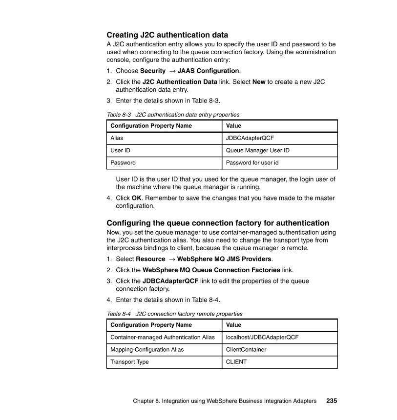
Creating J2C authentication dataA J2C authentication entry allows you to specify the user ID and password to be used when connecting to the queue connection factory. Using the administration console, configure the authentication entry:
1. Choose Security → JAAS Configuration.
2. Click the J2C Authentication Data link. Select New to create a new J2C authentication data entry.
3. Enter the details shown in Table 8-3.
Table 8-3 J2C authentication data entry properties
User ID is the user ID that you used for the queue manager, the login user of the machine where the queue manager is running.
4. Click OK. Remember to save the changes that you have made to the master configuration.
Configuring the queue connection factory for authenticationNow, you set the queue manager to use container-managed authentication using the J2C authentication alias. You also need to change the transport type from interprocess bindings to client, because the queue manager is remote.
1. Select Resource → WebSphere MQ JMS Providers.
2. Click the WebSphere MQ Queue Connection Factories link.
3. Click the JDBCAdapterQCF link to edit the properties of the queue connection factory.
4. Enter the details shown in Table 8-4.
Table 8-4 J2C connection factory remote properties
Configuration Property Name Value
Alias JDBCAdapterQCF
User ID Queue Manager User ID
Password Password for user id
Configuration Property Name Value
Container-managed Authentication Alias localhost/JDBCAdapterQCF
Mapping-Configuration Alias ClientContainer
Transport Type CLIENT
Chapter 8. Integration using WebSphere Business Integration Adapters 235

5. Click OK. Remember to save the changes that you have made to the master configuration.
8.6 Running the Stock Quote Retrieval scenarioNow that the development, deployment, and configuration is complete, you can test your new service.
Starting the JDBC adapterConfigure a start script shortcut to use WebSphere Application Server as the broker and the JDBC configuration file that you saved earlier:
1. Right-click the start_JDBC.bat file found in the C:\IBM\WebSphere\connectors\JDBC directory.
2. Choose New Shortcut.
3. Right-click the new shortcut and select Properties.
4. In the Target entry, append the following:
JDBC WAS -cC:\ITF\JDBCAdapter.cfg -fkey
5. Save the new shortcut.
Starting the ITE TEST server and launch test clientStart your server, and launch the business process client to test the adapter service:
1. Right-click the server TEST from the servers tab. Choose Start.
2. Right-click the server TEST from the servers tab. Choose Launch Business Process Web Client.
3. On the Process Web Client window, click the My Templates link.
4. Click the StockQuoteInfo template name. On the Process Template tab, select the retieveStockInfo service.
5. Enter IBM for the symbol, then click Start Instance in the available actions box (Figure 8-26 on page 237).
236 Managing Information Access to an EIS Using J2EE and Services Oriented Architecture

Figure 8-26 StockInfo business process Web client
The process runs and the console should print out the contents of the Quote Information and return the results to the calling Web service.
8.7 Creating the system processThe system process in this scenario is a multi-configuration process that facilitates the flexibility of switching and choosing a service provider using the context data information. This process was a key business requirement and growth opportunity that was mentioned in 3.1.3, “Business requirements” on page 69. For an overview of a system process, refer to 2.2.5, “Conceptual architecture” on page 37 and 2.2.6, “Logical architecture” on page 47.
Figure 8-27 on page 238 shows the multi-configuration context-based routing to different service providers implemented by the system process.
Chapter 8. Integration using WebSphere Business Integration Adapters 237

Figure 8-27 System process interaction - adapters service providers
The system process uses the context information to route the request, including the domain object, to the adapter service partner link. For this particular scenario, the partner link is the JDBC adapter service BPEL process, which does the data transformation and the request on the WebSphere Business Integration Adapter for JDBC.
The design and development of a system process using BPEL is explained in Chapter 9, “Integration into business processes” on page 241.
Here are the high-level steps that are required to incorporate the adapter process into the system process:
1. Map the InputVariable to the incoming domain object by setting the message file name to the system process WSDL that contains the domain schema. Then, set the message type on InputVariable.
2. In the Assign StockInfo snippet, set the data from the input variable into the adapter request variable, QuoteIn.
3. Create and map an OutputVariable to the outgoing domain object by setting the message file name to the system process WSDL that contains the domain schema. Then, set the message type on OutputVariable.
4. Set the returned result from the adapter, QuoteOut, into the corresponding values for the OutputVariable.
5. Integrate the adapter business process into the system process as the appropriate remote service call partner link.
System Process
PartnerLink(PL)
ContextAdapter Service
ProcessData Transformation
LOCAL
REMOTE
Domain Data
JDBC
Data Transformation
SAP
Adapter Service
Adapter Adapter for mySAP
Adapter for JDBC
PartnerLink(PL)
LOCAL
REMOTE
238 Managing Information Access to an EIS Using J2EE and Services Oriented Architecture

8.8 Quality of serviceThere are several quality of service features that the adapters provide. The adapter can use different security mechanisms, guaranteed delivery options, and easy to integrate functions.
The adapters provide application security by leveraging the applications security mechanism. The JDBC adapter can use the database user privileges to manage information access. Access to the adapter can also be managed by forcing users of the queue manager to authenticate prior to accessing to the queues.
During event notification, the adapters provide guaranteed event delivery, such that no data change in the EIS is lost on its way to the integration broker or client. Even when default event notification systems are not provided by the underlying EIS, the adapters generally include a triggering mechanism and event store feature to enable event propagation to the integration brokers.
The object discovery agent is a service not often found in EIS connectivity components. The ODA facilitates a quick and easy approach to developing business objects and incorporating them into the system.
8.9 More information about adaptersIf you would like more information about WebSphere Business Integration Adapters, see the following Web site:
http://www.ibm.com/software/integration/adapters
Chapter 8. Integration using WebSphere Business Integration Adapters 239

240 Managing Information Access to an EIS Using J2EE and Services Oriented Architecture

Chapter 9. Integration into business processes
This chapter discusses the integration of enterprise information systems (EIS) into business processes.
9
© Copyright IBM Corp. 2005. All rights reserved. 241

9.1 Managing business processesAn (SOA typically includes a business process management solution as its main building block. From a business perspective, the business processes are the procedures and rules that describe how the organization runs its business. From an IT perspective, a business process is the function of an IT application that supports users in completing a business-related task.
In an SOA, an IT business process calls services that are provided by components and applications which are enabled for the SOA infrastructure. Implementation of a business process management solution comprises all activities that are required to capture, design, develop, and run the business processes of an organization on the IT infrastructure.
Organizations have historically focused on departmental efficiency and common infrastructural concerns, such as implementing EIS systems for reporting and supply chain management. However, in today’s competitive world, the opportunity for differentiation lies in quick and efficient integration and automation of horizontal business processes. Often, business process efficiency cannot be achieved solely by purchasing packaged applications. The need for customization has lead to a series of home-grown applications that are integrated but often inefficient and expensive to maintain.
Enablement of the applications for an SOA and implementation of the business process in a dedicated business process management layer is the preferred solution for the optimization and integration problem. Successful organizations not only optimize and automate business processes, they achieve integration across these business processes, monitor them in execution, and provide real-time feedback to improve business processes in light of changes to their customers’ needs.
The key to improving and streamlining the business processes of an organization is bridging the business-technology gap through better communication between the stakeholders in the enterprise. More effective and timely coordination between ideas and execution is needed, all focusing on improvement results. The Process and Activity Flow and Framework (PAFF) provided by IBM is an approach that focuses on serving the business by tight alignment of business and technology.
One of the biggest chasms in an organization is the chasm between business and technology. Different stakeholders in an organization need a common way to communicate and to reduce the gap between business and technology. Line of business staff are concerned with understanding the business processes, including the costs, cycle times, resources, and bottlenecks in a process. Business analysts want to know which changes will yield the greatest return,
242 Managing Information Access to an EIS Using J2EE and Services Oriented Architecture

what the return on investment will yield, and how the changes will positively benefit the company. The IT group needs to understand the system requirements that are required to support the suggested improvements in the business process and should be able to accurately and quickly implement the process changes to meet the needs of the business. The key is to make seamless transitions between these stakeholders, from strategy to execution, while keeping an eye on the value proposition.
Codifying knowledge without needing to rekey, exporting data from simulated processes into financial spreadsheets, and moving from logical blueprints into physical assets are key attributes to providing benefits to the business and IT community. The PAFF software tools allow for dynamic generation of workflow as well as architectural diagrams that form the basis for the business improvement process, using languages and views that the IT community understands.
Figure 9-1 illustrates the elements of the PAFF methodology.
Figure 9-1 Business process life cycle
The process starts with modeling business processes and moving clockwise includes: analyze requirements, design and construct, deploy and run, and monitor. Except for the analyze requirements step, the following sections discuss
Analyze Requirements
Model BusinessProcess
LOB
SoftwareDevelopment
IT Operations
Develop Iteratively
Focus on Architecture
Continuously Ensure Quality
Manage Change & Assets
Design & Construct
DeployMonitor
AnalyzeRequirements
Chapter 9. Integration into business processes 243

the activities in more detail. Although the PAFF methodology is technology-agnostic, we focus on the Business Process Execution Language (BPEL) standard and the supporting WebSphere tools and infrastructure components.
9.1.1 Modeling of business processesLine of business staff and business analysts typically model the business processes of an organization. They have the skills and knowledge to define and optimize the processes. To capture the business processes and to document the business rules, they need tools. Often, they rely on office tools, such as text processors and drawing tools, to generate the business process and rules documentation.
PAFF, however, suggests using more powerful tools. WebSphere Business Integration Modeler provides a comprehensive environment for business process modeling. The tool includes:
� A visual modeling editor to create business process models.
� A palette of predefined modeling elements such as tasks and decision nodes.
� Definitions of business items which are the input and output of tasks.
� The documentation of processes and tasks by definition of resources, duration, and cost.
� Analysis and query capabilities to investigate the process details.
� Report generation to generate text and visual documentation.
� A simulation mode to simulate the business process and to analyze the process dynamics.
The first step in the modeling phase is to document the current process as it is and record as many data elements as possible so that you can run a simulation to understand the bottlenecks and inefficiencies. After you have determined a baseline process and all stakeholders have agreed that this process represents the current state, you next need to develop a new process by applying techniques to improve the process. Even if you intend to develop a new application and focus on the new process, we strongly recommend that you model the business processes by using WebSphere Business Integration Modeler. In many environments, we have seen that the tool improves the communication between business analysts and IT architects.
WebSphere Business Integration Modeler Version 5.1 is based on the Eclipse open source tool infrastructure. Because WebSphere Studio Application Developer Integration Edition is based on the same Eclipse infrastructure, seamless integration between both tools is provided. A combined installation of
244 Managing Information Access to an EIS Using J2EE and Services Oriented Architecture

both tools in a single environment is possible, so Modeler functions are provided in an additional perspective of WebSphere Studio Application Developer Integration Edition.
Business processes designed with Modeler V5.1 can be exported in BPEL format and therefore easily imported into the BPEL development environment. Modeler V5.1 also allows you to export the business process in UML format so that you can use Rational XDE Developer to detail the business process design. See “Modeling the business process” on page 250 for information about how to use the Modeler tools.
9.1.2 Developing business processesYou can develop BPEL-compliant business processes with WebSphere Studio Application Developer Integration Edition. You then deploy the generated artifacts on the Business Process Container of WebSphere Business Integration Server Foundation.
The BPEL standard includes specifications of modeling artifacts and structuring elements. Among others, the following artifacts are available:
� Partner links that describe parties that interact with the business process
� Invoke, receive, and reply activities to call services and to send and receive messages
� Variables to hold data in the business process that is sent to and received from services
� Sequence, flow, switch, and while elements that are used to structure the business process
The Business Process Container available in WebSphere Business Integration Server Foundation extends the BPEL specification by providing the following additional features:
� Staff activities that describe human interaction with the business process, for example approvals and data provisioning
� Service bindings to call services implemented in Java or as EJBs
� Java snippets that allow to run Java code from within the business process
The development of BPEL business processes using WebSphere Studio Application Developer Integration Edition is described in detail in 9.3.2, “Developing the BPEL process” on page 267. For more information refer to:
� WebSphere Business Integration Server Foundation V5.1 Handbook, SG24-6318
Chapter 9. Integration into business processes 245

� Using BPEL processes in WebSphere Business Integration Server Foundation. Business Process Integration and Supply Chain Solutions, SG24-6324
9.1.3 Deploying and running business processesYou must deploy the business process that is designed by arranging the BPEL elements into the BPEL process engine for execution. The deployment process results in the generation of an enterprise application (EAR module) that includes EJB modules and the BPEL file. You can install the generated EAR file on WebSphere Business Integration Server Foundation using the administration console.
If a client application initiates a BPEL process, the WebSphere Business Process Container triggers and executes the business processes. The process flow is interpreted, the potentially distributed services are called, and state changes in the business process are recorded. A business process can be interrupted until an external event indicates that the process can be resumed.
The abstract interface and technology binding describe the services called. If the internal service implementation changes, the business process is not affected. In case of changes in interfaces and technology, the process model is also not affected, but you have to update the service definitions.
The BPEL process engine records all state changes of business processes in its database. State changes typically occur after having successfully called services or having received events from external applications. Processes may also call other processes to form a nested business process model. The process engine records dependencies and the relationship between processes and their sub processes and therefore provides end-to-end state management. Exceptions thrown in sub processes are forwarded to and handled in the main process to provide an integrated exception handling mechanism. Exception handling is mainly a design issue, because system and service exception handling has to be modeled for the specific business process. The BPEL editor of WebSphere Studio Application Developer Integration Edition provides all of the required artifacts and concepts to support comprehensive exception handling, such as exception nodes and a compensation mechanism for undo actions.
Sub processes may share state and data if a specific modeling artifact (block) is used to define the sub processes. Processes can also be split up into parallel sub processes or branches that are executed concurrently. A specific modeling artifact (join) ensures that the main process continues only if all the sub processes have successfully ended.
246 Managing Information Access to an EIS Using J2EE and Services Oriented Architecture

Services may be called by static invocation. The details of the service to be called can be specified at development time. Dynamic invocation is also supported if services are registered in an appropriate registry (for example, a UDDI registry). In this case, the specific service to be called can be determined at runtime by requesting the service details from the registry.
Service invocations are typically atomic transactions. For example, sending a message to a message broker is controlled in a technical XA-capable transaction. Non-interruptible business processes are also executed in a transactional context. If services support the XA protocol, they become part of the global process transaction. In this case, technical rollback is possible. For interruptible business process, a compensation mechanism is provided to support application-specific rollback.
WebSphere Business Integration Server Foundation and the included process engine (Business Process Container) are extensions of the J2EE-compliant WebSphere Application Server. Because the process engine is implemented as a standard J2EE application that is running within a J2EE application server, all scalability and high availability mechanisms for this type of application are applicable.
Business process applications can be distributed across multiple application server instances and physical nodes to support concurrent processing of multiple business processes. The benchmark results published in various performance white papers show almost linear scaling with numbers of CPUs.
Because all service invocations are executed as atomic transactions and process state is recorded in a database, business processes are recoverable in case of failure of the process engine, application server, or physical node. It is also ensured that service invocations are not repeated in case of failures.
Standard high-availability concepts are applicable for the WebSphere Business Integration Server Foundation infrastructure. Typically, multiple-process engine instances are active for continuous availability. If a process engine fails, an automatic restart and takeover process ensures that in-flight business process that are running on the process engine resume. The database that all process engines are connected to should be configured in a high availability mode, for example, by using operating system-specific high availability solutions.
For more information refer to:
� WebSphere Business Integration Server Foundation V5.1 Handbook, SG24-6318
� WebSphere Business Integration Server Foundation Architecture and Overview, REDP-9129
Chapter 9. Integration into business processes 247

9.1.4 Monitoring business processesThe WebSphere process engine is managed by use of the administration console, which is implemented as Web application, and by use of standard WebSphere scripting mechanisms. In addition, WebSphere Business Integration Server Foundation provides a Web application to monitor execution of business processes, to manually suspend or end long-running processes, and to manage assignment and delegation of workflow activities of a business process to users.
Deployment of applications is supported by use of the administration console and by scripting mechanisms, respectively. For standard J2EE applications, multiple versions may be installed on separate application server instances. You can manually activate and deactivate these different application versions by starting and stopping the corresponding server instances, preferably using scripts. For BPEL applications, you can deploy multiple versions of business process flows on the server instances, which become active at a specific date and time.
More sophisticated monitoring capabilities are available in the WebSphere Business Integration Monitor product. WebSphere Business Integration Monitor Version 5.1 will extend monitoring and reporting capabilities that are available for WebSphere Business Integration Workflow and WebSphere Business Integration Message Broker and will include support for the WebSphere Business Integration Server Foundation environment. The currently available WebSphere Business Integration Monitor Version 4.2 offers:
� The ability to monitor work-in-process items based on the user perspective and to perform corrective actions by reassigning, re-prioritizing, or suspending those items
� The ability to represent monitored information in an event way, not just process- and activity-centric
� The business process dashboard for tracking processes, work items, and business performance measures
� The report builder to choose the layout of reports and the information and graphics used to visualize information
� Rules-based alerts and support for multiple user notification methods (dashboard, e-mail, and mobile)
WebSphere Business Integration Monitor Version 5.1 will be integrated with WebSphere Business Integration Modeler and will include the capability to feedback real-time process data into process models.
248 Managing Information Access to an EIS Using J2EE and Services Oriented Architecture

9.2 Modeling and designing business processesBusiness process modeling is performed mainly by business analysts. These subject matter experts usually do not have detailed IT knowledge. The challenge for software development methodologies and project management is to enable the business analysts to provide sufficient information to IT architects and designers so that the design reflects the business requirements.
This chapter focuses on the methodology and tools that can ensure unbiased flow of information from business analyst to IT architect and designer. It shows in detail how you can model and design business processes using WebSphere Business Integration Modeler, Rational XDE Developer, and WebSphere Studio Application Developer Integration Edition.
9.2.1 Modeling the stock trade scenarioThe stock trade scenario was described in detail in 3.1, “Scenario description and requirements” on page 66. In summary, in the stock trade use case, a customer intends to buy or sell stock using the Web channel of a trading firm. The web-enabled stock trade application calls the stock trade business process to process the customer request. The stock trade business process itself relies on two other business processes that are run by the brokerage division of that trading firm and by an external stock quote and analysis firm.
The three business processes that built up the end-to-end scenario have been specified using WebSphere Business Integration Modeler. The modeling tool was mainly used in the requirements capture phase of our project. For all three business processes, activity flows have been created using the visual process editor of WebSphere Business Integration Modeler. We have noticed that the definition of a business use case is accelerated significantly, if the modeling tool is used in a requirements capture workshop, even for our rather simple sample scenario. In most cases, the reports and figures that can be easily generated with the modeling tool provide a sufficient level of detail to completely describe the functional requirements on a business level. Sharing these documents across a team of business analysts improves collaboration and provides for more effective and efficient discussions.
To facilitate the design of the business processes, more details have been added to the process flows in the visual editor. Business items, such as trade details or order details, have been specified using the business item editor of the tool. Input and output of the activities and the overall process have been defined. Furthermore, for all decisions in the process flow, expressions have been specified to determine the branch to follow in the flow. By using the easy-to-use editors and expression builders, business analysts are able to specify in detail
Chapter 9. Integration into business processes 249

the data and process flow in the business process and to provide the design team with the necessary information to start immediately with design activities.
IT architects and designers often prefer to use standard UML notation to capture designs and development methodologies, and they often enforce the use of UML-compliant architecture models. WebSphere Business Integration Modeler includes a UML export feature to generate XMI-based descriptions of the process model. The UML model can then be imported into modeling tools such as Rational XDE Developer. Seamless integration of the modeling tools enables IT-architects and designers to design interfaces and data models that are based on UML-compliant analysis models that are generated by business analysts. Because re-creation of the analysis models from text documents or free-form drawings is not required, a common cause of discrepancies between business requirements and design is eliminated.
9.2.2 Modeling the business processThe business process models have been developed using WebSphere Business Integration Modeler Version 5.1. You can find detailed instructions about how to install the product in the installation package.
Creating the business modeling projectWhen starting WebSphere Business Integration Modeler for the first time, the Quickstart wizard opens to assist you in creating a modeling project and a process model. At this screen, you can enter the names of a project, process catalog, and process (see Figure 9-2 on page 251). In addition, you can use the next screen of the wizard to create a business item catalog and a business item. Deselect the Always show this wizard on startup check box if you do not want the wizard to start when the modeler tool is started. You can open the wizard at any time by selecting Modeling → Quickstart wizard → Model a process from the menu bar.
250 Managing Information Access to an EIS Using J2EE and Services Oriented Architecture
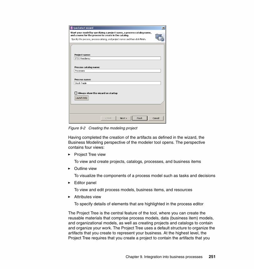
Figure 9-2 Creating the modeling project
Having completed the creation of the artifacts as defined in the wizard, the Business Modeling perspective of the modeler tool opens. The perspective contains four views:
� Project Tree view
To view and create projects, catalogs, processes, and business items
� Outline view
To visualize the components of a process model such as tasks and decisions
� Editor panel
To view and edit process models, business items, and resources
� Attributes view
To specify details of elements that are highlighted in the process editor
The Project Tree is the central feature of the tool, where you can create the reusable materials that comprise process models, data (business item) models, and organizational models, as well as creating projects and catalogs to contain and organize your work. The Project Tree uses a default structure to organize the artifacts that you create to represent your business. At the highest level, the Project Tree requires that you create a project to contain the artifacts that you
Chapter 9. Integration into business processes 251

create. Within the project, the Project Tree creates a library that contains folders for organizing your model elements. To create a process model within the Processes folder, for example, right-click the folder and select New → Process. Within the folders, you can add your own specific catalogs, each of which holds a related set of items. You can also create catalogs within catalogs, in case you want to organize information hierarchically.
All items that you create in the Project Tree below the level of catalogs and projects are reusable. When you create a business item, for example, you can reuse it whenever you need to supply a data type. Similarly, a process that you create in the Project Tree is reusable as a subprocess within other processes.
The Editor panel, Outline view, and Attributes view are used to visualize and detail the process models and business items that you have created. The following sections explain these views in more detail.
Stacked behind the Attributes view, two more views are available: the Control Panel view and the Error view. The Control Panel view is used to configure and start simulations, which is not covered in this book. In the Error view, error and warning messages are displayed that the modeler tool creates when validating modeling projects and process models.
Creating the process modelThe process editor is the feature that you use to graphically compose the details of a process model. If you have used the Quickstart wizard to create a modeling project and process model, the process editor is already open in the editor panel. You can open the process editor at any time by double-clicking the process in the Project Tree.
The process diagram is accompanied by a palette that contains elements that you can add to the process diagram. For the Stock Trade business process models, we used the following elements:
� Tasks: activities of a business process� Start and Stop nodes: indicate start and end of a business process� Decisions: allow to split process flow and to follow multiple branches� Merges: merge multiple branches into one� Connections: connect activities and nodes to define the process flow
You usually start modeling in the operational mode and use the Basic user profile. The operational mode allows for unrestricted modeling, while the FDL and the BPEL mode enable restrictions so that transformation to FDL- and BPEL-based descriptions of the process model is facilitated. The Basic user profile focuses on business modeling tasks. In contrast, the Intermediate profile that you use later, allows for definition of input and output data for processes and tasks and provides formal expressions for decisions. You can switch between
252 Managing Information Access to an EIS Using J2EE and Services Oriented Architecture

modes and user profiles by selecting Modeling → Modes or Modeling → User profile from the menu bar.
To define non-reusable elements, select the elements in the palette and drag them onto the diagram. To add reusable processes and tasks, you first have to create them in the Project Tree, and then you add the elements to a process diagram by dragging them from the Project Tree. In the Stock Trade business processes, we have used non-reusable tasks only. In a more complex scenario, we recommend that you create a collection of reusable processes and tasks to ensure reuse and consistency across process models that are created by different business analysts.
Figure 9-3 on page 254 shows the process editor for the Stock Brokerage business process. You can find the palette on the left side of the process editor. Three tasks, a decision, and connections are shown in the process model diagram.
To create connections between tasks you first have to click the Connections button (the button with the arrow to the right) on the palette to enable the connection creation mode. You leave this mode by clicking the Select button (the button at the top) of the palette.
Chapter 9. Integration into business processes 253

Figure 9-3 Creating the process model
Defining business items and data flowThe business item editor provides the location where you can specify the attributes for business items that you create in the Project Tree. Business items are reusable. You create business items by highlighting the Business Items folder in the Project tree and selecting New → Business Item. The business item editor for the specified business item opens after its creation. You can open the business item editor at any time by double-clicking on the business item in the Project Tree.
Figure 9-4 on page 255 depicts the business item editor for the Order Details data object. To create new attributes for business items, click Add. The name and type of the attribute are selected by clicking the corresponding table cell in the editor. To select the available types, click the button that appears in the table cell. You can choose from a set of standard data types, such as String and Long, or you can select any business item that you have defined.
254 Managing Information Access to an EIS Using J2EE and Services Oriented Architecture

Figure 9-4 Creating a business item
Having created the business items for your process you are now able to define the data flow in the process model. To create inputs and outputs for tasks and to associate business items to connections you have to switch to the Intermediate user profile.
Define the data flow for the process model by right-clicking connections and selecting Associate Data. You select the data type from the list of standard data types and business items. WebSphere Business Integration Modeler creates inputs and outputs for the tasks that are connected.
You can define additional inputs and outputs in the Attributes view. Figure 9-5 on page 256 shows the Stock Analysis process model and the Attributes view for the Validate Request task. Use the Add button to create and specify the input
Chapter 9. Integration into business processes 255

and output for that task. In the process editor you are then able to connect task outputs with matching task inputs.
Figure 9-5 Associate data to task inputs and outputs and to connections
In most cases, the process itself also has an input and output. You specify process input and output in the Attributes view at the Input and Output tab, respectively. Make sure that you click inside the process (do not highlight any element) to set the scope for the process.
Note: If you associate data for connections to inputs of decision or merge nodes, additional outputs are created. Their data type corresponds to the data type of the input. You might have to delete the empty outputs and reconnect tasks using the outputs that the modeler tool creates.
256 Managing Information Access to an EIS Using J2EE and Services Oriented Architecture
Detailing decisionsDecision elements are used to model branches in the process model and are dependent on context information that the process follows in different branches in the flow. We recommend that you specify the branch conditions already in the requirements capture phase. Because the data flow through the decision nodes has been defined, business item attributes can be used to specify decisions in more detail.
WebSphere Business Integration Modeler provides an expression builder that you can access from the Output Branches tab in the Attributes view. If you cannot see the tab, make sure that you highlight the decision node in the process model to set the scope for the decision. In the Output Branches tab, you also have to select the branch for which you are defining the condition. Figure 9-6 on page 258 shows the expression builder.
Chapter 9. Integration into business processes 257

Figure 9-6 Expression builder for decisions
To specify the branch condition, you first select the business item attribute from the list below the label First Term. Then you chose from operators that are available for the attribute. Finally, you select either another modeling artifact, text, or order number from the list below the label Second Term. Click Apply to save the branch constraint. The expression is displayed in the Expression text field. You may repeat these steps for all branches of the decision node.
The Stock Trade business processesTo illustrate the results of our requirements capture activities, the Stock Trade business processes are depicted in the following figures. Figure 9-7 on page 259
258 Managing Information Access to an EIS Using J2EE and Services Oriented Architecture
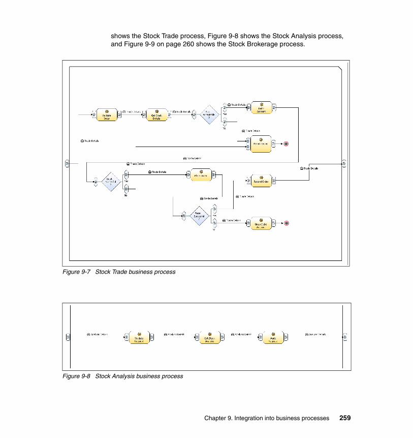
shows the Stock Trade process, Figure 9-8 shows the Stock Analysis process, and Figure 9-9 on page 260 shows the Stock Brokerage process.
Figure 9-7 Stock Trade business process
Figure 9-8 Stock Analysis business process
Chapter 9. Integration into business processes 259

Figure 9-9 Stock Brokerage business process
9.2.3 Designing business processes and servicesThe process models have been imported into Rational XDE Developer 2003 and WebSphere Studio Application Developer Integration Edition for further refinement. Because both tools are based on Eclipse, XDE Developer can be installed on top of Integration Edition. The XDE tools are then available from the Modeling perspective within Integration Edition. You can find detailed instructions on how to install the products in the installation package.
Exporting the process model from ModelerYou can export a process model to a UML 1.4 compliant XMI file that you can then import into Rational XDE Developer. To export a process model as UML, complete the following steps:
1. Select the project, catalog, or element that you want to export in the Project Tree. Right-click and select Export. The Export wizard appears.
2. Select UML Business Modeling Profile and click Next.
3. Click Browse to select the target directory where you want to put the project. Select the project to export from the drop-down list.
4. Click Finish. The name of the file is the name of the modeling project, and the file extension is .xml.
We have exported the complete modeling project including process models and business items. We recommend that you at least export these artifacts, because they provide the most value for IT architects and designers. For our sample scenario, we have not defined resources such as roles, timetables, and
260 Managing Information Access to an EIS Using J2EE and Services Oriented Architecture

resources (instances of roles). If you create resources, exporting the resource catalog may be useful, particularly if you assign resources to activities of the process model. This resource assignment can be visualized later in the UML activity graph.
Exporting the process model to a BPEL-compliant description is similar to exporting UML. Use the Export wizard, but now select the WebSphere Business Integration Server Foundation V5.1 profile. The export wizard creates BPEL files, WSDL files to describe the process interfaces, and XML Schema (XSD) descriptions for the business items that are defined.
Importing the UML process modelYou can import the UML 1.4 XMI file that you exported from WebSphere Business Integration Modeler into Rational XDE Developer. Because the exported XMI file does not contain any diagram information, you must create diagrams using the imported model elements after importing the model file. To import the process model:
1. Start Rational XDE Developer and switch to the Modeling perspective. From the main menu bar, select File → New and create a simple project.
2. Select File → Import. For the file to import, select the XMI file that you have exported. For the directory, browse to the simple project you just created. Click Finish.
3. In the Model Explorer view, find the model that has the new project name. You may have to open the model by double-clicking on the model file in the Navigator view. Under the model, you may find Data catalogs, Process catalogs, Resource catalogs, Organization catalogs, and Business Integration Modeler Classes packages.
4. To display the class diagram that includes business items of your data catalog, open the main diagram in the data catalog folder by choosing Data catalogs → Business Items → Main.
5. Drag and drop the classes in that folder onto the diagram to visualize them.
6. To create an activity diagram for a process model, select an activity graph in the model by choosing Process catalogs → Processes → Business Use Case Stock Trade → Top.
7. Right-click, and select Add Diagram → Activity. Enter the diagram name. An empty diagram is created.
8. Select all the elements under the Top activity graph (not including the activity diagram) and drag and drop them onto the empty diagram. For a simple process, select Diagram → Arrange from the main menu bar. For a complex process, you may have to rearrange elements manually.
Chapter 9. Integration into business processes 261

We have imported the Stock Trade process models and data into Rational XDE Developer. Figure 9-10 depicts the Stock Brokerage activity diagram.
Figure 9-10 Stock Brokerage activity diagram
Figure 9-11 shows the class diagram, including all the business items that we have defined.
Figure 9-11 Stock Trade class diagram (analysis)
Start
End
Audit Order
Buy Stock
Sell StockValidate Order
Buy or Sell ?
Merge
[ 'Processes.Stock Brokerage.Stock Brokerage.Buy or Sell ?.Input.Quantity'
is greater than 0.0]
[ 'Processes.Stock Brokerage.Stock Brokerage.Buy or Sell ?.Input.Quantity'
is less than 0.0]
«Business Entity»Analysis Details
+ Target 1Y[1..1] : String+ Volume[1..1] : String+ Change[1..1] : String+ Last Trade[1..1] : String+ Stock[1..1] : String
«Business Entity»Order Details
+ Account[1..1] : String+ Price Limit[1..1] : String+ Quantity[1..1] : Long+ Stock[1..1] : String
«Business Entity»Trade Details
+ Order Acknowledge[1..1] : String+ Account Debit Acknowlwdge[1..1] : String+ Risky Inclination[1..1] : String
+ Order Details
1
262 Managing Information Access to an EIS Using J2EE and Services Oriented Architecture

Importing the BPEL process modelThe BPEL-compliant process models that have been exported from WebSphere Business Integration Modeler can be imported into WebSphere Studio Application Developer Integration Edition.
When you import into Integration Edition, it is important to import the folder structure that was generated while exporting the processes, because the generated files use that structure to reference one another. To import the files from any directory, complete the following steps:
1. In Integration Edition, ensure that you are in the Business Integration perspective.
2. Create a new service project as follows:
a. In the Services navigator, select File → New → Service Project.
b. In the New Project window that opens, enter the name of the project that you are planning to import.
c. Click Finish to create the new project.
3. Right-click the project and select Import.
4. In the Import wizard, select File system. Click Next.
5. Click Browse and select the directory where you exported the files from WebSphere Business Integration Modeler. Place a checkmark beside the directory and click Finish.
6. The files are imported into the project you have selected. Double-click the processes to open the BPEL editor.
Designing services and data modelAs described in “Modeling and designing business processes” on page 249, business analysts define the analysis model using the WebSphere Business Integration Modeler tool. The design model, however, has to be developed by IT architects by redefining process and data model.
The architect’s main task is to map the activities of the analysis process model to services. You can either reuse services, meaning that you map the required function to functions already available from applications or components. In case you cannot reuse application services, you have to design new service implementations. We recommend that you design and implement all new services using Java and J2EE technology. The tools for design and implementation are provided by Rational XDE Developer and WebSphere Studio Application Developer Integration Edition.
Furthermore, you have to create and refine the process design. We describe how to design and implement the BPEL process in 9.3, “Developing business
Chapter 9. Integration into business processes 263

processes” on page 266. The data model for the process and the services can be created with tools that are provided by Rational XDE Developer. Refer to the Rational XDE Developer documentation for details on how to use the tool. The main steps to create the data types are:
1. Create a Java or EJB modeling project and a Java or EJB code model.
2. Add packages, Java classes, or EJBs that are needed to detail the data model.
3. Generate code for all UML elements that you have defined.
Having successfully completed the code generation, Java data types including attributes and relationships are available that can be used later to implement the services and the BPEL process. To design the WSDL interfaces, however, XML schemas are needed. XML schemas can be generated from Java objects using WebSphere Studio Application Developer Integration Edition tools.
Designing the process and service interfacesFrom an SOA perspective, all elements in the architecture are services and are described by a WSDL interface definition. Both BPEL processes and the invoked services are described by their WSDL interfaces.
WebSphere Studio Application Developer Integration Edition provides a WSDL editor that we used to design the process interfaces. As an example, we show the steps to create the interface for the trader system process in more detail. The process model is depicted in Figure 6-6 on page 139.
The trader system process requires a StockOrderRequest business object as input and returns a StockOrderConfirmation object. XML schema definitions for the business objects have already been generated when we created the Trader EIS service as detailed in 6.4.3, “Enabling the EIS component using JMS” on page 156.
To create a WSDL interface definition, complete the following steps:
1. In the Business Integration perspective, select File → New → Service Interface to create the WSDL file.
2. Specify a package name and a file name (for example, com.itso and TraderSPInterface), and click Finish.
3. In the WSDL editor, in the Imports section at the top-left, right-click and select Add child → Import. Make sure that the entry that appears in the Imports section remains selected and go to the Ellipses button next to Location (Figure 9-12 on page 265).
264 Managing Information Access to an EIS Using J2EE and Services Oriented Architecture

Figure 9-12 Import XML schemas into WSDL interface definitions using the WSDL editor
4. From the Select wizard, navigate to the XSD file to import (for example, StockOrderConfirmation.xsd). Click OK.
5. Go to the Port Types section to define a new operation. Right-click the port type (for example, TraderSPInterface), and select Add child → operation. Enter the name of the operation (for example, invokeTraderSP).
6. To create input and output parameters, highlight the operation and select Add child → Input and Add child → Output.
7. Create a message that describes the input by highlighting the input and selecting Set Message. From the Specify Message wizard, choose the Create a new Message option, and enter the name of the message (for example, invokeTraderSPRequest). Also, specify the output message.
8. Messages comprise parts. Create a part for each message by highlighting the message and selecting Add Child → Part. Enter the name of the part (for example, request).
9. For the parts, set the type by right-clicking and selecting Set Type. From the Specify Type wizard, choose the Select an existing type option and select the type from the list (for example, xsd1:StockOrderRequest). (This is the data structure that you imported in step 4). Click Finish.
Chapter 9. Integration into business processes 265

Figure 9-13 depicts the WSDL editor showing the interface definition for the Trader system process.
Figure 9-13 WSDL editor showing the Trader system process interface
9.3 Developing business processesThis section describes how to develop a BPEL process using WebSphere Studio Application Developer Integration Edition. It first describes the design of the process and then explains in detail how the BPEL editor of Integration Edition was used to visually construct the process. Finally, it discusses process deployment and configuration of WebSphere Business Integration Server Foundation.
9.3.1 EIS integration into BPEL processesIn our approach for EIS integration, EIS services are invoked from system processes. In the system process, the decision is made regarding how the service is called. If the service invocation requires data transformation, an EIS
266 Managing Information Access to an EIS Using J2EE and Services Oriented Architecture

component might be called. In case a remote service has to be invoked, a JMS binding can be used to communicate with the service.
The following sections describe how to develop the trader system process that we designed in 6.4.1, “The stock trade scenario” on page 137.
In this system process we demonstrate the invocation of the EIS functions using three different integration styles:
� We directly invoke the EIS service using the IMS bindings that we have created with the WebSphere Studio Application Developer Integration Edition tools.
� We invoke the EIS component that we have developed using direct EJB calls, meaning that we call a local EIS component.
� We invoke the EIS component using sender beans and Message Driven Beans, means that we use JMS technology to call a remote EIS component.
Each of these integration styles has specific characteristics that affect the development of the process. Calling the IMS service directly requires that data transformations are performed in the process. Data transformation can be implemented in the BPEL process either by using Transformation nodes or by coding Java Snippets.
If the EIS component is invoked by JMS messages, the system process includes a send activity to send the message. The BPEL process may also include a pick activity to receive the confirmation message. because the process has to wait for the message, the process has to be marked as interruptible process. This means the process itself has to be triggered by using JMS. Introducing a pick activity also requires the configuration of a correlation set to distinguish the trigger and initialize messages for the process from reply messages sent by the EIS component.
9.3.2 Developing the BPEL processThis section describes the steps to create the trader system process in detail. It first explains how to create a service project and the basic outline of the process. Then, it describes the creation of service bindings that are used in the BPEL process. Finally, it demonstrates the use of the BPEL editor by successively adding the EIS service invocations to the process.
Creating a service project and a BPEL processWhen you start WebSphere Studio Application Developer Integration Edition, the Business Integration perspective opens by default. The Business Integration
Chapter 9. Integration into business processes 267
perspective provide all tools that you need to create BPEL processes and service bindings.
To create a new Service project:
1. Select File → New → Service Project form the main menu bar.
The project appears in the Services view on the top-left of the panel. Stacked behind the Services view, you find a Package Explorer view and a J2EE hierarchy view that you can use to browse the projects.
2. At this point you might wish to import all XML schemas and WSDL definitions that you have created when designing the BPEL process and services. Import files by highlighting the project and selecting File → Import.
To create a new BPEL process:
1. Select File → New → Business Process from the menu bar.
2. Enter a package name and the name of the business process and click Next.
3. In the Choose process type window, specify the type of the process.
Selecting the WSAD-IE v5.0 Business Process option leads to the generation of a business process that is compliant to the previous version of WebSphere Studio Application Developer Integration Edition. A BPEL-compliant process is created if you select the Flow-based BPEL Process option or the Sequence-based BPEL Process option. We prefer to use a flow-based style.
4. Click Finish.
The wizard creates a number of artifacts that appear in the Services and Package Explorer view and the BPEL editor opens. In Figure 9-14 on page 269 the BPEL editor shows the initial trader system process. Because in most cases you define a specific interface for process, you can delete the generated partner link and input variable. Right-click the partner link in the BPEL editor and select Delete. Then delete the input variable.
We have described how to create the WSDL interface of the trader system process in 9.2.3, “Designing business processes and services” on page 260. To specify the process interface, a new partner link has to be created that refers to the WSDL definition of the process interface.
268 Managing Information Access to an EIS Using J2EE and Services Oriented Architecture
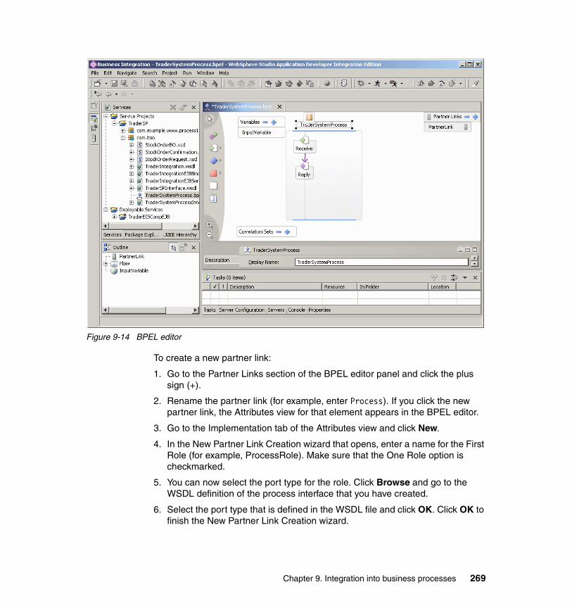
Figure 9-14 BPEL editor
To create a new partner link:
1. Go to the Partner Links section of the BPEL editor panel and click the plus sign (+).
2. Rename the partner link (for example, enter Process). If you click the new partner link, the Attributes view for that element appears in the BPEL editor.
3. Go to the Implementation tab of the Attributes view and click New.
4. In the New Partner Link Creation wizard that opens, enter a name for the First Role (for example, ProcessRole). Make sure that the One Role option is checkmarked.
5. You can now select the port type for the role. Click Browse and go to the WSDL definition of the process interface that you have created.
6. Select the port type that is defined in the WSDL file and click OK. Click OK to finish the New Partner Link Creation wizard.
Chapter 9. Integration into business processes 269

7. The port type appears in the Implementation tab. The role that we have defined is a role that our business process provides to external clients. Specify this role by clicking <--> in the Implementation tab.
Figure 9-15 shows the partner link for the trader system process.
Figure 9-15 Process partner link for the Trader system process
While the Receive node of the BPEL process represents the inbound operation for the process, the Reply node represents the outbound operation. We also have to set operation and message for both nodes to specify the process interface. To set operation and message:
1. Select the Receive node and go to the Implementation tab.
2. Use the Partner Link drop-down to select the partner link (for example, Process). Because we have defined only one port type and only one operation, the fields below the drop-down are set correctly.
3. To create the inbound message in the BPEL process click New to the right of Request. Enter the name of that variable (for example ProcessInput), and click OK.
Figure 9-16 shows the resulting Implementation tab for the Receive node.
Figure 9-16 Operation and variable settings for the Trader receive node
270 Managing Information Access to an EIS Using J2EE and Services Oriented Architecture
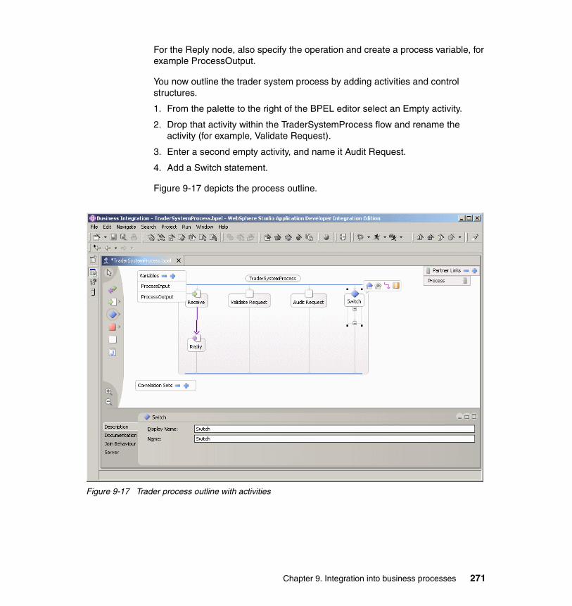
For the Reply node, also specify the operation and create a process variable, for example ProcessOutput.
You now outline the trader system process by adding activities and control structures.
1. From the palette to the right of the BPEL editor select an Empty activity.
2. Drop that activity within the TraderSystemProcess flow and rename the activity (for example, Validate Request).
3. Enter a second empty activity, and name it Audit Request.
4. Add a Switch statement.
Figure 9-17 depicts the process outline.
Figure 9-17 Trader process outline with activities
Chapter 9. Integration into business processes 271
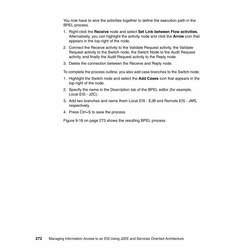
You now have to wire the activities together to define the execution path in the BPEL process.
1. Right-click the Receive node and select Set Link between Flow activities. Alternatively, you can highlight the activity node and click the Arrow icon that appears in the top-right of the node.
2. Connect the Receive activity to the Validate Request activity, the Validate Request activity to the Switch node, the Switch Node to the Audit Request activity, and finally the Audit Request activity to the Reply node.
3. Delete the connection between the Receive and Reply node.
To complete the process outline, you also add case branches to the Switch node.
1. Highlight the Switch node and select the Add Cases icon that appears in the top-right of the node.
2. Specify the name in the Description tab of the BPEL editor (for example, Local EIS - J2C).
3. Add two branches and name them Local EIS - EJB and Remote EIS - JMS, respectively.
4. Press Ctrl+S to save the process.
Figure 9-18 on page 273 shows the resulting BPEL process.
272 Managing Information Access to an EIS Using J2EE and Services Oriented Architecture
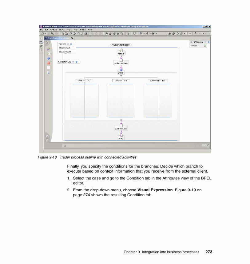
Figure 9-18 Trader process outline with connected activities
Finally, you specify the conditions for the branches. Decide which branch to execute based on context information that you receive from the external client.
1. Select the case and go to the Condition tab in the Attributes view of the BPEL editor.
2. From the drop-down menu, choose Visual Expression. Figure 9-19 on page 274 shows the resulting Condition tab.
Chapter 9. Integration into business processes 273
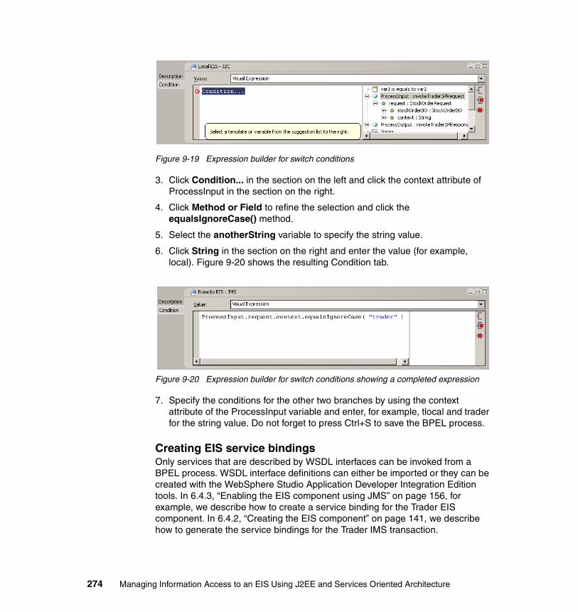
Figure 9-19 Expression builder for switch conditions
3. Click Condition... in the section on the left and click the context attribute of ProcessInput in the section on the right.
4. Click Method or Field to refine the selection and click the equalsIgnoreCase() method.
5. Select the anotherString variable to specify the string value.
6. Click String in the section on the right and enter the value (for example, local). Figure 9-20 shows the resulting Condition tab.
Figure 9-20 Expression builder for switch conditions showing a completed expression
7. Specify the conditions for the other two branches by using the context attribute of the ProcessInput variable and enter, for example, tlocal and trader for the string value. Do not forget to press Ctrl+S to save the BPEL process.
Creating EIS service bindingsOnly services that are described by WSDL interfaces can be invoked from a BPEL process. WSDL interface definitions can either be imported or they can be created with the WebSphere Studio Application Developer Integration Edition tools. In 6.4.3, “Enabling the EIS component using JMS” on page 156, for example, we describe how to create a service binding for the Trader EIS component. In 6.4.2, “Creating the EIS component” on page 141, we describe how to generate the service bindings for the Trader IMS transaction.
274 Managing Information Access to an EIS Using J2EE and Services Oriented Architecture

Using the tools, you can create service bindings from Java classes, Enterprise JavaBeans, and EIS functions that can be accessed using a J2C connector. You open the Service Creation wizard by selecting File → New → Service built from. For more details on the Service Creation wizard, refer to the WebSphere Studio Application Developer Integration Edition help.
For the trader system process, we imported service interface descriptions for the three services that we call from the system process:
� The Trader J2C IMS transaction
� The Trader integration bean of the EIS component
� The sender bean that sends requests to the JMS-enabled Trader EIS component
Invoking the J2C IMS service To use an external service in a BPEL process, you create a partner link that describes the service provider and its service. You detail the partner link by specifying the WSDL service interface description.
The BPEL process editor creates a partner link and configures it as soon as you drop a WSDL service description on the panel. For example, we imported the Trader IMS service description into the service project. Select TraderEISIMSService.wsdl and drop it on BPEL editor showing the trader system process. From the pop-up that appears you may select the port type you want to import. In our example, we have defined only one port type per WSDL service description, so you can accept the default. As a result, a new partner link is created, in our example its name is TraderEIS.
To invoke the service in the process flow, you have to add an Invoke activity and then you select partner link, port type, and operation for the activity. To add the Invoke activity, select the Invoke template from the palette of the BPEL editor, and drop it on the process. In our example, we invoke different services in the different branches of the Switch node. So, first drop an Invoke activity on the Local EIS - J2C case of the Switch node and rename it, for example enter InvokeIMSService.
Chapter 9. Integration into business processes 275

The IMS service that we call requires input parameters that we have to set before we invoke the service. J2C-based services are often characterized by complex data structures that require either a Transformation node or a Java snippet. For the TraderEISIMSService, we demonstrate the use of Java snippets for data transformation. Add two Java snippets to the switch case, for example AssignIMSRequest for outbound data transformation and AssignIMSResponse for inbound transformation. Connect the nodes so that the execution path becomes AssignIMSRequest - InvokeIMSService - AssignIMSResponse. Figure 9-21 shows the process flow.
Figure 9-21 J2C IMS service invocation
276 Managing Information Access to an EIS Using J2EE and Services Oriented Architecture
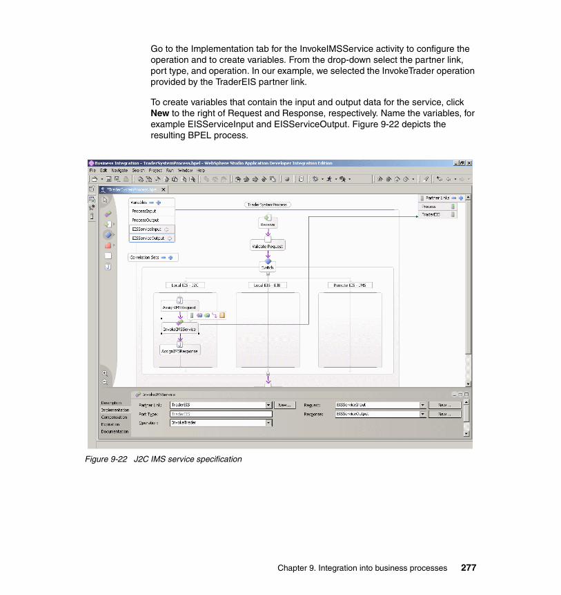
Go to the Implementation tab for the InvokeIMSService activity to configure the operation and to create variables. From the drop-down select the partner link, port type, and operation. In our example, we selected the InvokeTrader operation provided by the TraderEIS partner link.
To create variables that contain the input and output data for the service, click New to the right of Request and Response, respectively. Name the variables, for example EISServiceInput and EISServiceOutput. Figure 9-22 depicts the resulting BPEL process.
Figure 9-22 J2C IMS service specification
Chapter 9. Integration into business processes 277

To set the variables during process execution, code fragments have to be added to the Java snippets. Go to the Implementation tab of the Java snippets to enter code. Example 9-1 shows the code for the AssignIMSRequest snippet.
Example 9-1 Code for the AssignIMSRequest Java snippet
int insize = new INBUFFERFormatHandler().getSize();InvokeTraderSPRequestMessage its = getProcessInput();InvokeTraderRequestMessage itr = getEISServiceInput();
INBUFFER in = new INBUFFER();in.setIn__zz((short) 0);in.setIn__ll((short) insize);in.setIn__trcd("TRADERBl");in.setRequest__type("Buy_Sell");in.setUpdate__buy__sell("1");in.setUserid(its.getRequest().getStockOrderBO().getAccount());in.setNo__of__shares__dec((short)its.getRequest().
getStockOrderBO().getQuantity());in.setCompany__name(its.getRequest().getStockOrderBO().getStock());
itr.setINBUFFER(in);setEISServiceInput(itr);
Example 9-2 shows the code for the AssignIMSResponse snippet.
Example 9-2 Code for the AssignIMSResult Java snippet
InvokeTraderSPResponseMessage itr = getProcessOutput();InvokeTraderResponseMessage itrs = getEISServiceOutput();
StockOrderConfirmation confirmation = new StockOrderConfirmation();StockOrderBO sbo = new StockOrderBO();confirmation.setMessage("Transaction completed");sbo.setAccount(itrs.getOUTBUFFERPart().getUserid());sbo.setQuantity((int) itrs.getOUTBUFFERPart().getNo__of__shares__dec());sbo.setStock(itrs.getOUTBUFFERPart().getCompany__name());
itr.setResponse(confirmation);setProcessOutput(itr);
You can test the process at this stage.
1. Right-click the BPEL process in the Service view and select Enterprise Services → Generate Deploy Code.
2. Accept the defaults and click OK.
WebSphere Studio Application Developer Integration Edition creates all artifacts required to run the BPEL process, including an EJB and an
278 Managing Information Access to an EIS Using J2EE and Services Oriented Architecture

Enterprise Application module. You might have to add Java snippets to the other two branches, because BPEL validation can fail if empty switch cases are detected.
Add the Enterprise Application to a WebSphere Business Integration Server Foundation test server, publish the applications, and start the server. You can start the business process by using the business process Web client. Refer to the WebSphere Studio Application Developer Integration Edition help for more details on how to test business processes.
Invoking the EIS component service using EJB bindingBecause the Trader EIS component consists of EJBs, the BPEL process is able to call the EJBs directly using the EJB binding. EJB service descriptions can be created with the Service Creation Wizard by selecting File → New → Service built from.
We have created a service description that includes the EJB binding for the TraderIntegration session bean of The Trader EIS component. The EJB service description, for example TraderIntegrationEJBService.wsdl, has to be dropped on the BPEL editor to create a partner link. The EJB-based service is called from an Invoke activity that needs to be configured as described in the previous section. Also, variables for inbound and outbound data need to be created.
Because the Trader EIS component accepts business objects, setting outbound data objects and inbound objects is easier. Instead of coding the data transformation in Java snippets, we can now use Assign activities. Assign activities are available from the palette of the BPEL editor.
Assign activities do not contain Java code. They are configured in the Implementation tab of their Attributes view. Data mapping is supported in the editor by specifying the variable that provides the data in the left column. The variable that has to be initialized is selected in the right column. The Assign activity does not support transformation between data types. Data types of the structures selected in both columns must match. Figure 9-23 on page 280 depicts the data mapping editor for the AssignEISRequest activity.
Chapter 9. Integration into business processes 279

Figure 9-23 Mapping of process variables using an Assign activity
Invoking the EIS component service using JMSIn case a remote EIS component has to be called from the BPEL process, JMS is used to communicate with the EIS component that is located close to the back-end system. The Trader EIS component provides a sender bean that can be used by a client to send requests. Also, an MDB is provided to process the reply messages from the EIS component in the client.
To configure an Invoke activity to call the sender bean, you have to create a service description for the sender bean. We again selected the EJB binding to call the sender bean from the BPEL process. First, you have to drop the service description of the sender bean on the process to create a BPEL partner link. Then, you add an Invoke activity to the process. In the implementation tab of the Invoke activity, specify the port type and operation of that partner link, and crate input and output variables. You can use assign activities to set these variables.
The sender bean sends a message to the EIS components and returns. To receive the reply from the EIS component in the BPEL process, the MDB that receives the message has to forward it to the BPEL process. The BPEL specification provides a specific construct, the Pick activity, to receive and process confirmation messages from external services and systems.
To add a Pick activity to the process:
1. Select the Pick icon from the palette of the BPEL editor and drop it on the process.
The Pick activity is similar to a Switch node because it provides multiple onMessage branches for different messages that may arrive. In our case, we only need one branch.
2. Highlight the Pick node and select the Add onMessage icon that appears in the top-right of the node.
280 Managing Information Access to an EIS Using J2EE and Services Oriented Architecture

3. Specify the name in the Description tab of the BPEL editor, for example receiveEISReply. Figure 9-24 depicts the resulting BPEL process.
Figure 9-24 Integration of the EIS component into the BPEL system process using JMS
4. For the Invoke activity, specify the partner link, port type, and operation in the Implementation tab of the Attributes view. Figure 9-25 on page 282 shows the selected operation and the created input and out variables for the SendEISRequest activity.
Chapter 9. Integration into business processes 281

Figure 9-25 Invoke activity specification for calling the JMS sender bean
5. Set up the input variable for the sender bean invocation using an Assign activity. Figure 9-26 shows the mapping of the process input variable to the input for the sender bean call .
Figure 9-26 Mapping of the sender bean input variable
Introducing a Pick activity means that the process must stop until the reply message is received. You specify that a process is interruptible and long-running in the Server tab of the Attributes view for the process. Make sure to select the process by highlighting the icon with the process name on the top of the BPEL editor panel. Go to the Server tab and checkmark the Process is long-running option, as depicted in Figure 9-27 on page 283.
282 Managing Information Access to an EIS Using J2EE and Services Oriented Architecture
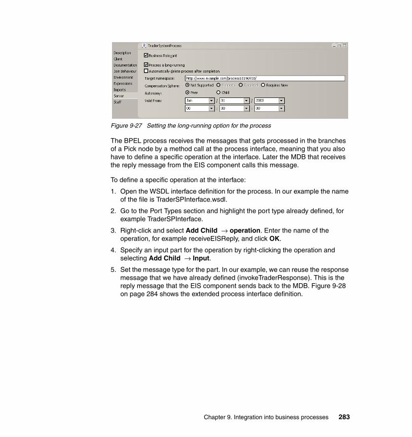
Figure 9-27 Setting the long-running option for the process
The BPEL process receives the messages that gets processed in the branches of a Pick node by a method call at the process interface, meaning that you also have to define a specific operation at the interface. Later the MDB that receives the reply message from the EIS component calls this message.
To define a specific operation at the interface:
1. Open the WSDL interface definition for the process. In our example the name of the file is TraderSPInterface.wsdl.
2. Go to the Port Types section and highlight the port type already defined, for example TraderSPInterface.
3. Right-click and select Add Child → operation. Enter the name of the operation, for example receiveEISReply, and click OK.
4. Specify an input part for the operation by right-clicking the operation and selecting Add Child → Input.
5. Set the message type for the part. In our example, we can reuse the response message that we have already defined (invokeTraderResponse). This is the reply message that the EIS component sends back to the MDB. Figure 9-28 on page 284 shows the extended process interface definition.
Chapter 9. Integration into business processes 283

Figure 9-28 Trader system process interface including the receiveEISReply operation
The operation has now to be selected in the onMessage branch that we introduced earlier. Highlight the branch in the BPEL editor and go to the Implementation tab. From the drop-down menu, select the process partner link and the operation that we defined in the previous steps. A new process variable is not required in our example. Because we have selected for the same message type as for the process output, we can select the process output variable from the drop-down to the right of the Request.
In a BPEL process engine, typically, a number of process instances of a specific type are active in parallel. They are either running or they are suspended because they are waiting for a message to arrive. The process engine has to select the right process instance, if a message is received from a client that called the receive operation at the process interface. BPEL supports the correlation of message and process instance by correlation sets. A correlation set can contain a number of attributes of messages that are sent by service invocations and that are received at the process interface.
284 Managing Information Access to an EIS Using J2EE and Services Oriented Architecture

To create a correlation set:
1. Click the plus sign (+) to the right of Correlation Sets in the BPEL editor.
2. Rename the correlation set (for example, ReceiveEISReply). You define the attributes that are contained in the correlation set in the Properties tab of the Attributes view. In our example, we only use the Account attribute of the StockOrderBO to correlate the reply message that is sent by the EIS component and the process instance.
3. Click New in the Properties tab to create a new property.
4. In the Create Message Property window enter the name (for example, account). Select the Built-in Type option and select xsd:String, because the Account attribute is a String.
Aliases describe the mapping of the property to message parts that have to be used for correlation. To create aliases:
1. Click New. Select the WSDL file in which the messages are defined (for example, the process interface definition TraderSPInterface.wsdl).
2. Select the message and part and click OK. Figure 9-29 shows the Create Property Alias wizard.
Figure 9-29 Create property alias wizard
Figure 9-30 on page 286 depicts the completed property definition for the correlation set that we have defined in the sample process.
Chapter 9. Integration into business processes 285

Figure 9-30 Create message property wizard
The final step is to configure the Receive and Pick activities to use the correlation set.
1. Highlight the Receive activity of the process and go to the Correlation tab in the Attributes view of the BPEL editor.
2. Click Add to add a correlation set. Because you have defined only one correlation set, you do not have to select the correlation set to add.
3. The Direction column indicates whether the message is sent or received. For the Receive activity, select the Receive setting.
4. The Initiation column indicates whether the activity initializes the properties of the correlation set. For the Receive activity, select Yes. Figure 9-31 shows the settings for the Receive activity.
Figure 9-31 Correlation settings for the Receive activity
286 Managing Information Access to an EIS Using J2EE and Services Oriented Architecture
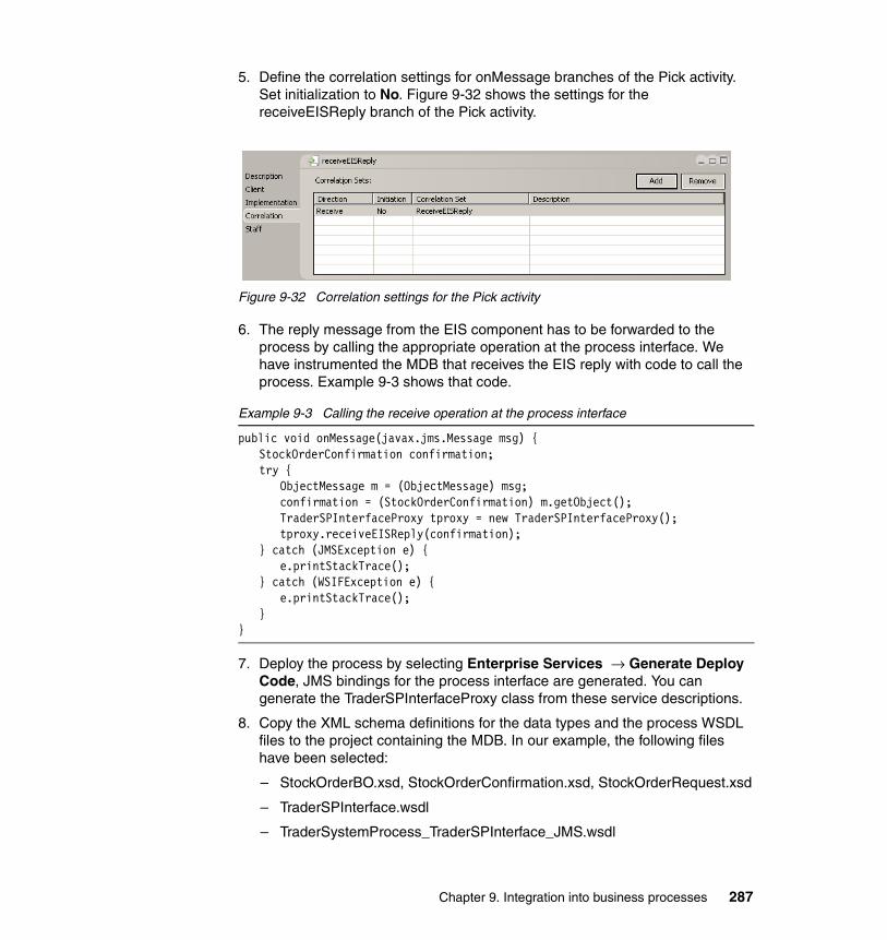
5. Define the correlation settings for onMessage branches of the Pick activity. Set initialization to No. Figure 9-32 shows the settings for the receiveEISReply branch of the Pick activity.
Figure 9-32 Correlation settings for the Pick activity
6. The reply message from the EIS component has to be forwarded to the process by calling the appropriate operation at the process interface. We have instrumented the MDB that receives the EIS reply with code to call the process. Example 9-3 shows that code.
Example 9-3 Calling the receive operation at the process interface
public void onMessage(javax.jms.Message msg) {StockOrderConfirmation confirmation;try {
ObjectMessage m = (ObjectMessage) msg;confirmation = (StockOrderConfirmation) m.getObject();TraderSPInterfaceProxy tproxy = new TraderSPInterfaceProxy();tproxy.receiveEISReply(confirmation);
} catch (JMSException e) {e.printStackTrace();
} catch (WSIFException e) {e.printStackTrace();
}}
7. Deploy the process by selecting Enterprise Services → Generate Deploy Code, JMS bindings for the process interface are generated. You can generate the TraderSPInterfaceProxy class from these service descriptions.
8. Copy the XML schema definitions for the data types and the process WSDL files to the project containing the MDB. In our example, the following files have been selected:
– StockOrderBO.xsd, StockOrderConfirmation.xsd, StockOrderRequest.xsd
– TraderSPInterface.wsdl
– TraderSystemProcess_TraderSPInterface_JMS.wsdl
Chapter 9. Integration into business processes 287

9. Generate the TraderSPInterfaceProxy class by right-clicking the process interface, TraderSystemProcess_TraderSPInterface_JMS.wsdl, and selecting Enterprise Services → Generate Service Proxy.
10.Create a proxy object of type Client stub and select all operations that are defined in the WSDL interface description.
9.3.3 Deploying BPEL processesWhen WebSphere Studio Application Developer Integration Edition generates deploy code, an EJB module including the BPEL process and a number of other artifacts is created. The EJB module is added to an Enterprise Application archive. To run and debug the BPEL process, you must install this Enterprise Application archive on a WebSphere Business Integration Server Foundation test server.
You can configure a test server in WebSphere Studio Application Developer Integration Edition from the server perspective.
1. In the Server Configuration view, right-click and select New → Server and Server Configuration.
2. Enter a name for the server and select Integration Test Environment as the server type.
3. Add the Enterprise Application, including the BPEL process, to the server by right-clicking the server and selecting Add and remove projects.
4. Deploy the applications to the server by selecting Publish.
To run the BPEL process in the test environment of WebSphere Studio Application Developer Integration Edition, no specific configuration of the server is required. If you deploy interruptible, long-running processes, select Create tables and data sources before you start the server. For long-running processes, entity beans are needed that require definition and setup of database tables and the configuration of a DataSource. You can create process instances using the business process Web client. Start the client by selecting Launch Business Process Web Client.
If you wish to deploy and run the processes using a standalone WebSphere Business Integration Server Foundation installation, configuration and setup of the process engine is required.
9.4 Qualities of service for business processesThis section focuses on non-functional requirements. Non-functional requirements such as security and high-availability have been described for the
288 Managing Information Access to an EIS Using J2EE and Services Oriented Architecture
BPEL implementation from IBM in various white papers and Redbooks. The following sections address two other important requirements: transaction support and usability of technology and tools.
9.4.1 Transaction supportIn 9.1.3, “Deploying and running business processes” on page 246, we introduce the transactional support in the BPEL process engine of WebSphere Business Integration Server Foundation. BPEL business processes are atomic transactions if the process is short-running and non-interruptible. In this case, service invocations are part of the global process transactions. If services support transactions, for example EJB invocations and J2C-based services, technical rollback using the XA protocol is performed in case of failures.
If BPEL processes are long-running and interruptible, the process consists of a series of single transactions, typically including one service invocation. For long-running processes there is no transactional context spanning the whole business process. Instead, WebSphere Business Integration Server Foundation introduces the notation of compensation to undo activities in case of failures.
Compensation requires that services functions can be undone. For instance, a log record that was created in a database in the beginning of process execution can be deleted later if service invocation of another function fails. An e-mail that was sent to confirm a client’s order cannot be withdrawn and deleted in case later in the process it is detected that the order item is out of stock. A possible undo action would be to send another e-mail informing the customer that the item is no longer available.
Compensations is initiated if faults occur in a business process. Faults are indicated by an exception that is thrown by an activity or another business process that are invoked in the process. Exceptions have to be specified in the WSDL service description of the service or business process. To introduce compensation in a BPEL process the following tasks have to be performed:
� Add exceptions to the WSDL description of the operations that are used to invoke the service or business process.
� Add fault handlers for activities and business processes to catch or rethrow exceptions.
� Enable compensation for the business process by setting the Compensation Sphere attribute to Required.
� Select undo operations for activities that have to be invoked if compensation is performed.
Chapter 9. Integration into business processes 289
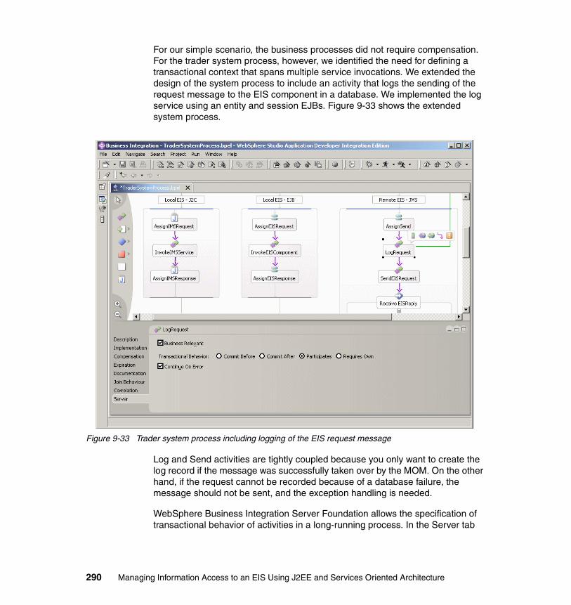
For our simple scenario, the business processes did not require compensation. For the trader system process, however, we identified the need for defining a transactional context that spans multiple service invocations. We extended the design of the system process to include an activity that logs the sending of the request message to the EIS component in a database. We implemented the log service using an entity and session EJBs. Figure 9-33 shows the extended system process.
Figure 9-33 Trader system process including logging of the EIS request message
Log and Send activities are tightly coupled because you only want to create the log record if the message was successfully taken over by the MOM. On the other hand, if the request cannot be recorded because of a database failure, the message should not be sent, and the exception handling is needed.
WebSphere Business Integration Server Foundation allows the specification of transactional behavior of activities in a long-running process. In the Server tab
290 Managing Information Access to an EIS Using J2EE and Services Oriented Architecture

depicted in Figure 9-33 on page 290 the options are shown. The Transactional behaviour field provides four choices:
� Commit Before
Use this setting if your activity must be committed immediately after it has completed. This activity tolerates being in a transaction with other activities that precede it.
� Commit After
Use this setting if the transactions that precede it must be fully committed before it can begin. This activity tolerates being in a transaction with other activities that follow it.
� Participates
Use this setting if this activity does not require a commit to occur either before or after it, and where it can coexist within a transaction where one or more other activities are invoked.
� Requires Own
Use this setting when this activity must be isolated within its own transaction.
By selecting these options for multiple activities correctly, blocks of activities can be defined in a long-running BPEL process that share the transactional context. If the service supports the XA protocol, for example EJBs interacting with a relational database or sending messages via WebSphere MQ, technical rollback of invocations is possible.
9.4.2 Usability of BPEL technology and toolsA BPEL-based business process is a series of business-related activities that are invoked in a specific sequence to achieve a business goal. In BPEL, a process is composed of partners, activities, elements, and variables.
� The partners are the external users or services that interact with the process.
� The activities are the individual business tasks within the process that compose the larger business goal.
� The elements supplement activities and assist them in accomplishing their tasks. They are nested within the activities with which they interact.
� The variables store the messages that are passed between these activities and partners.
Chapter 9. Integration into business processes 291
BPEL tool setUsing WebSphere Studio Application Developer Integration Edition, you can assemble processes in a graphical tooling environment, called the BPEL process editor, and deploy it to a separate run-time environment that executes it.
Process editorThe Process editor is a graphical programming environment that you use to visually create and manipulate business processes. The BPEL-based Process editor displays a visual representation of an instance of the Business Process Execution Language. It builds upon the existing functionality of the language and adds a number of useful extensions like Java snippets and Staff activities.
Using the Process editor is almost like creating a new Graphical User Interface (GUI) panel using widgets from a pallet. When you create a GUI panel, you typically drag-and-drop your widgets onto a panel, align them, set custom properties for the GUI widgets, and add event handling.
With the Process editor, you select activities from a palette which you drop onto a canvas. You can then set custom properties for the activities in the details area of your Process editor and link your activities together using control links, if you have a flow-based BPEL process. So, it would appear that creating a new business process using the Process editor is almost like creating a new GUI panel, using the Visual Editor for Java in WebSphere Studio Application Developer.
Having a graphical view of a business processes will revolutionize the way you build and interact with your business process. However, you must be aware that there are a lot of artifacts and components generated by the Process editor, especially when you generate deploy code.
In a multi-developer, multi-project type of environment you must consider how you want to manage, control and maintain all of the components, projects and artifacts being produced behind the scenes. For example, if you are working with Rational Clear Case and you want to generate deploy code from a process that is under the control of Clear Case, confirm that all of the relevant files have been checked out of the repository or else the generation will fail.
The Process editor generates a lot of artifacts behind the scenes, and it also depends on a other artifacts from other services or business processes in other projects. Carefully consider how you want to approach, manage, and maintain such a development environment between multiple developers or multiple project teams.
292 Managing Information Access to an EIS Using J2EE and Services Oriented Architecture
DocumentationThe documentation is good, intuitive, easy to read and understand, and it is readily available. In WebSphere Studio Application Developer Integration Edition, click Help → Help Contents to bring up the Information Center. Select WebSphere Studio on the left. Select Developing → Processes → The Process editor (BPEL).
The online help contains detailed information explaining how to use the Process editor, create processes, and set attribute values in the Attributes view of the Process editor. It also explains concepts and describes all of the BPEL activities. This is an excellent source of information that you should read before you start developing your own business processes in the Process editor.
Note: Do not get a false sense of security that the tool will do everything for you. Indeed, the tool does generate most (if not all in certain scenarios) of the artifacts, components, and projects for you.
Rather than clients calling your business processes directly, in some situations you might want to add another layer of abstraction between consumers of your business process and the actual process. You might want to consider doing common processing in a service end-point, such as request and response handling, caching, security, adding your own custom SOAP handlers, and so on.
Common architecture, design and implementation standards, principles , and patterns must be adhered to. A principle concern should be stability through interfaces. In a services-based architecture using Web services technologies, you should layer your service end-points, typically using an interaction and processing layer. Designing your service interface, and designing the business process (service implementation) requires the same effort.
Chapter 9. Integration into business processes 293

For additional online documentation on Business Process Choreographer you can visit these sites:
� WebSphere Business Integration Server Foundation Process Choreographer:
http://ibm.com/developerworks/websphere/zones/was/wpc.html
� Process Choreographer Concepts and Architecture White paper:
http://ibm.com/developerworks/websphere/library/techarticles/wasid/WPC_Concepts/WPC_Concepts.html
DebuggerUsing WebSphere Studio Application Developer Integration Edition, you can debug your business processes by setting break points in Java snippet activities and on control links, before or after some activities. The ability to debug your BPEL business processes will help you to deliver robust processes. The performance of the debugger at the time of writing this book is quite slow. You would need a powerful development workstation with a lot of memory and processing power to debug BPEL processes. This performance might affect your project delivery if you are on a critical path and need to trace a problem using the debugging tool.
Suggestion: Naming standards are especially important. Consider documenting your naming standards before you begin to create your processes projects in your development tool.
We suggest that you have naming standards for at least the following:
� Service projects� EJB projects� Java and utility projects� Web projects� Package names� WSDL files� BPEL
– Business process names– Process activities– Process exception handlers– Variables (or message definitions in WSDL files)
Behind the scenes, most of the projects, components, or artifacts are being generated for you. If you or your project team must change names later in your project, the effort to re-factor, re-deploy, and re-build could potentially effect the delivery of your project.
294 Managing Information Access to an EIS Using J2EE and Services Oriented Architecture

BPEL technologyIf you have been implementing message flows in WebSphere Business Integration Message Broker or process flows in WebSphere Business Integration Workflow, then you are probably familiar with a lot of the concepts of BPEL technology.
BPEL aims to provide a language that formally specifies business processes based on Web services, thus extending the Web services interaction model to support business processes. IBM have extended the standard BPEL specification (sometimes referred to as BPEL+) to support Java snippet and Staff activities.
Using a services-based architecture style, we exposed our components and business processes using Web services technologies. We created composite applications by using (or rather reusing) services. BPEL is crucial for business process interoperability across Web services. Running business processes over Web services is crucial for enterprise adoption of Web Services.
BPEL is best suited to provide the standards-based solution that addresses not only business process representation and execution but also the sharing of business processes across disparate systems. Business processes specified in BPEL are fully executable and they are portable between BPEL compliant environments. A BPEL business process interoperates with the Web services of its partners, whether these Web services are realized based on BPEL.
BPEL is based on XML and WSDL. WSDL offers a very flexible binding framework. SOAP over HTTP is only one binding. Other bindings allow developers to reach out to EJB/RMI components, JMS destinations or even Java objects without any performance degradation. The only constraint is that the input and output parameters have to be describable using XML schema. However, this is a very good constraint because it creates an important abstraction which allows for better tooling.
For additional information about the specification, you can refer to the Business Process Execution Language for Web Services Version 1.1 at:
http://ibm.com/developerworks/library/ws-bpel/
Definition: BPEL is an XML-based language for describing a flow of messages across a set of services. Example:
� First send message A to service A� Then wait until you receive message B from service B� Then tranform message B into message C� Then send message C in parallel to service D and Service F
Chapter 9. Integration into business processes 295

SummaryAt the time of writing this Redbook, the team used WebSphere Studio Application Developer Integration Edition Version: 5.1.0 Build id: 20040319_0845 for creating and testing our BPEL processes in the Process editor.
The Process editor tool is easy to use, if you understand the key concepts. Some of the key concepts you must be familiar with are:
� Flow- versus sequence-based BPEL processes
� Which activities are available, when, where, how, and why you would use each activity
� Transactions and compensation handling
� Correlation sets
� Partner links
� Variables
� Exception handling
� WSIF: if you want to invoke your business processes using the BusinessProcess or LocalBusinessProcess session bean
You do have the ability to debug your BPEL processes, but at the time of the writing of this book, the debugger performance was slow. It was quite a time consuming process to trace a BPEL business process.
We expect that BPEL will continue to move forward and serve as the primary foundational technology for executable business process descriptions. We also expect that BPEL runtime environments and tools will move forward to provide a efficient, effective, stable, and performant environment for business process implementations.
296 Managing Information Access to an EIS Using J2EE and Services Oriented Architecture

Appendix A. Deploying the sample code
This appendix provides details of how to work with the sample code that is provided with this redbook. To obtain the sample code follow the instructions in Appendix B, “Additional material” on page 307.
Sample code filesThis section assumes that you have obtained the redbook sample code as described in Appendix B, “Additional material” on page 307 and unzipped the sg246371.zip file. In this case, a directory called sg246371 is created. The following folders and files are included in the sample material:
� Chapter2
– ch02projects.zip
This zipped file contains projects exported from WebSphere Studio Application Developer Integration Edition V5.1.1. The projects are the samples detailed in Chapter 2, “Architecture” on page 9. See “Working with the Chapter2 sample files” on page 301 for more details of the files in this zipped file. For details of how to import projects from this zipped file see “Importing projects from a zipped file” on page 300.
– ch02workspace.zip
This zipped file contains a zipped workspace for WebSphere Studio Application Developer Integration Edition V5.1.1. The workspace includes
A
© Copyright IBM Corp. 2005. All rights reserved. 297

all the samples detailed in Chapter 2, “Architecture” on page 9. See “Working with the Chapter2 sample files” on page 301 for more details of this workspace zipped file.
� Chapter5
– ch05projects.zip
This zipped file contains projects exported from WebSphere Studio Application Developer Integration Edition V5.1.1. The projects are the samples detailed in Chapter 5, “Using J2EE Connector Architecture” on page 95. See “Working with the Chapter5 sample files” on page 302 for more details of the files in this zipped file. For details of how to import projects from this zipped file, see “Importing projects from a zipped file” on page 300.
– ch05workspace.zip
This zipped file contains a workspace for WebSphere Studio Application Developer Integration Edition V5.1.1. The workspace includes all the samples detailed in Chapter 5, “Using J2EE Connector Architecture” on page 95. See “Working with the Chapter5 sample files” on page 302 for more details of this workspace zipped file.
� Chapter7
– ch07projects.zip
This zipped file contains projects exported from WebSphere Studio Application Developer Integration Edition V5.1.1. The projects are samples that illustrate the technology discussed in Chapter 7, “Using Web services” on page 165. See “Working with the Chapter7 sample files” on page 302 for more details of the files in this zipped file. For details of how to import projects from this zipped file, see “Importing projects from a zipped file” on page 300.
– ch07workspace.zip
This zipped file contains a workspace for WebSphere Studio Application Developer Integration Edition V5.1.1. The workspace includes samples that illustrate the technology discussed in Chapter 7, “Using Web services” on page 165. See “Working with the Chapter7 sample files” on page 302 for more details of this workspace zipped file.
� Chapter8
– ch08projects.zip
This zipped file contains projects exported from WebSphere Studio Application Developer Integration Edition V5.1.1. The projects are the samples detailed in Chapter 8, “Integration using WebSphere Business Integration Adapters” on page 199. See “Working with the Chapter8
298 Managing Information Access to an EIS Using J2EE and Services Oriented Architecture

sample files” on page 303 for more details of the files in this zipped file. For details of how to import projects from this zipped file see “Importing projects from a zipped file” on page 300.
– ch08workspace.zip
This zipped file contains a workspace for WebSphere Studio Application Developer Integration Edition V5.1.1. The workspace includes all the samples detailed in Chapter 8, “Integration using WebSphere Business Integration Adapters” on page 199. See “Working with the Chapter8 sample files” on page 303 for more details of this workspace zipped file.
– samples.zip
This zipped file contains various files used to setup for the samples detailed in Chapter 8, “Integration using WebSphere Business Integration Adapters” on page 199. See “Working with the Chapter8 sample files” on page 303 for more details of the files in this zipped file.
� Chapters6and9
– ch06and9projects.zip
This zipped file contains projects exported from WebSphere Studio Application Developer Integration Edition V5.1.1. The projects are the samples detailed in Chapter 6, “EIS integration using Java Message Service” on page 121 and in Chapter 9, “Integration into business processes” on page 241. See “Working with the Chapter6and9 sample files” on page 304 for more details of the files in this zipped file. For details of how to import projects from this zipped file see “Importing projects from a zipped file” on page 300.
– ch06and92workspace.zip
This zipped file contains a workspace for WebSphere Studio Application Developer Integration Edition V5.1.1. The workspace includes all the samples detailed in Chapter 6, “EIS integration using Java Message Service” on page 121 and in Chapter 9, “Integration into business processes” on page 241. See “Working with the Chapter6and9 sample files” on page 304 for more details of this workspace zipped file.
– samples.zip
This zipped file contains various files used to setup for the samples detailed in Chapter 6, “EIS integration using Java Message Service” on page 121 and in Chapter 9, “Integration into business processes” on page 241. See “Working with the Chapter6and9 sample files” on page 304 for more details of the files in this zipped file.
Appendix A. Deploying the sample code 299

Importing projects from a zipped fileTo import projects from the projects zipped files included in our sample material:
1. Start WebSphere Studio Application Developer Integration Edition V5.1.1 by choosing Start → Programs → IBM WebSphere Studio → Application Developer Integration Edition 5.1.1.
2. Choose File → Import.
3. Select Project Interchange as the import source and click Next (Figure A-1).
Figure A-1 Import source
4. Click Browse and select the correct projects zipped file.
5. Click Select All to choose all projects in the zipped file and then click Finish (Figure A-2 on page 301).
300 Managing Information Access to an EIS Using J2EE and Services Oriented Architecture
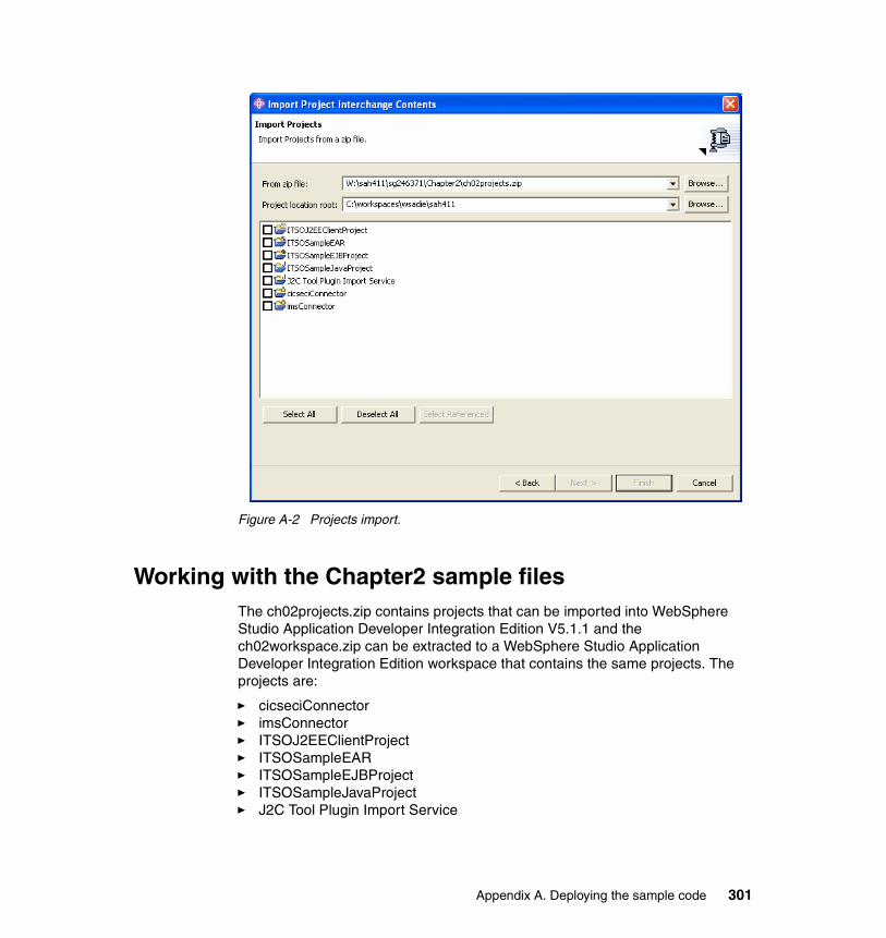
Figure A-2 Projects import.
Working with the Chapter2 sample filesThe ch02projects.zip contains projects that can be imported into WebSphere Studio Application Developer Integration Edition V5.1.1 and the ch02workspace.zip can be extracted to a WebSphere Studio Application Developer Integration Edition workspace that contains the same projects. The projects are:
� cicseciConnector� imsConnector� ITSOJ2EEClientProject� ITSOSampleEAR� ITSOSampleEJBProject� ITSOSampleJavaProject� J2C Tool Plugin Import Service
Appendix A. Deploying the sample code 301

To work with these samples, you need access to CICS and IMS test systems where you have installed and configured the Trader application samples described in the WebSphere for z/OS V5 Connectivity Handbook, SG24-7064. You also need to configure a test server in WebSphere Studio Application Developer Integration Edition and set up its J2C resources to access your CICS and IMS systems.
Working with the Chapter5 sample filesThe ch05projects.zip contains projects that can be imported into WebSphere Studio Application Developer Integration Edition V5.1.1 and the ch05workspace.zip can be extracted to a WebSphere Studio Application Developer Integration Edition workspace that contains the same projects. The projects are:
� cicseciConnector� CICSJCA� CICSJCAEAR� CICSJCAEJB� CICSJCAWeb� J2C Tool Plugin Import Service
To work with these samples, you need access to a CICS test system where you have installed and configured the Trader application sample described in the WebSphere for z/OS V5 Connectivity Handbook, SG24-7064. You also need to configure a test server in WebSphere Studio Application Developer Integration Edition and set up its J2C resources to access your CICS system.
Working with the Chapter7 sample filesThe ch07projects.zip contains projects that can be imported into WebSphere Studio Application Developer Integration Edition V5.1.1 and the ch07workspace.zip can be extracted to a WebSphere Studio Application Developer Integration Edition workspace that contains the same projects. The projects are:
� StockAnalysisBP� StockAnalysisBPEAR� StockAnalysisBPEJB� StockAnalysisBPWeb� StockAnalysisSP� StockAnalysisSPEAR� StockAnalysisSPEJB
302 Managing Information Access to an EIS Using J2EE and Services Oriented Architecture

� StockAnalysisSPWeb� ValidatorEAR� ValidatorWeb� Servers
These projects comprise two service projects which developed the business process and the system process for the redbook Stock Analysis sample the requirement of which are described in “Stock Analysis Service” on page 82. There is also a Web services project (Validator) that can be used to test the stock analysis service.
Working with the Chapter8 sample filesThe ch08projects.zip contains projects that can be imported into WebSphere Studio Application Developer Integration Edition V5.1.1 and the ch08workspace.zip can be extracted to a WebSphere Studio Application Developer Integration Edition workspace that contains the same projects. The The projects are:
� cicseciConnector� JDBCAdapter� JDBCAdapterEAR� JDBCAdapterEJB� JDBCAdapterWeb� J2C Tool Plugin Import Service
The samples.zip file should be extracted to temporary folder. It contains:
� a readme.txt file
� Configure MQ folder
– The configure_mq.txt file can be used to define the WebSphere MQ queues used by the JDBC adapter
� Database folder
– The CreateStockInfoTable.txt file can be used to define and load the STOCKINFO database table used by the sample code
– The stockdbdata.txt file contains sample data for the STOCKINFO table
� The WAS Adapter Export folder contains the WebSphere Application Server project files exported from the System Manager as described in 8.5.4, “Building and exporting the adapter project” on page 217
Appendix A. Deploying the sample code 303

Working with the Chapter6and9 sample filesThe ch06and09projects.zip contains projects that can be imported into WebSphere Studio Application Developer Integration Edition V5.1.1 and the ch06and09workspace.zip can be extracted to a WebSphere Studio Application Developer Integration Edition workspace that contains the same projects. The The projects are:
� IMSConnector� IMSServiceEAR� IMSServiceEJB� Servers� TraderEISCompEAR� TraderEISCompEJB� TraderLogEJB� TraderSP� TraderSPEAR� TraderSPEJB� TraderSPWeb� J2C Tool Plugin Import Service
Note that the samples.zip file contains many of the same projects found in the ch06and09projects.zip, but it also has modelling and design files. You should extract the samples.zip file to a temporary folder. It contains:
� A readme.doc file
� ITSO Residency.zip
This file contains the business process models developed to describe the Stock Trade scenario. It is a WebSphere Business Integration Modeler export file. It contains the business items Analysis Details, Order Details, and Trade Details. It includes process models Stock Analysis, Stock, Brokerage, and Stock Trade.
� JMSJCADesign.zip
The file contains the EJB code model for the Trader EIS Component developed with XDE developer. The code model includes the StockOrderBO, StockOrderRequest, and StockOrderConfirmation java classes. It also contains the TraderIMSFeature EJB and the TraderIMSIntegration EJB. UML diagrams as shown in 6.4, “Develop EIS integration using JMS” on page 137 have been created from this model.
304 Managing Information Access to an EIS Using J2EE and Services Oriented Architecture

� IMSService.jar
The file contains the IMS access code generated with WebSphere Studio Application Developer Integration Edition. It includes:
– The WSDL files including the IMS binding: Trader.wsdl, TraderIMS*.wsdl
– The utility classes: INPUT, OUTPUT, WSIF Format Handlers
– The proxy class to call the IMS transaction: TraderProxy.java
– The JUnit test class to test the proxy: TraderProxyTest.java
� TraderEISCompEAR.ear
This EAR file contains the TraderEISCompEJB module and utility Jars required to compile the module (IMSService.jar, IMSServiceEJB.jar). The TraderEISCompEJB module includes the following EJBs:
– The IMS feature session bean: TraderIMSFeature
– The EIS component session bean: TraderIntegration
– The MDB that processes incoming messages and calls TraderIntegration: TraderIntegrationMDB
– The session bean to sent the reply back to clients: TraderReply
� IMSServiceEAR.ear
This EAR file contains the client code for the EIS component. The EJBs have been used to test the Trader EIS component. Later they have also been included in the Trader system process (BPEL) to call the EIS component. The EAR includes utility JARS required to compile the module (IMSService.jar, TraderEISCompEJB.jar) and the IMSServiceEJB module which has the following EJBs:
– The session bean to create and send the JMS request to the Trader EIS component: TraderIntegrationTest
– The MDB to receive and log the reply from the EIS component: TraderReplyTest
� TraderLogEJB.jar
The EJB module contains the two EJBs used to log the request message sent to the EIS component (see 9.4.1, “Transaction support” on page 289s). The module contains:
– The entity bean used to log the request in the database: LogCMP
– The session that creates the LogCMP objects on request: LogSB
Appendix A. Deploying the sample code 305

� TraderSPService.zip
The zipped file that contains the service project with BPEL process and WSDL definitions. It includes:
– The BPEL system process: TraderSystemProcess.bpel
– The WSDL interface of the BPEL process: TraderSPInterface.wsdl
– The service description of the J2C IMS service: TraderEIS*.wsdl
– The service description of the EIS component (EJB): TraderIntegration(EJB)*.wsdl
– The service description of the EIS component (JMS): TraderIntegrationSend(EJB)*.wsdl
– The service description of the Log service: LogRequest(EJB).wsdl
– The XML schema definitions of the business objects used in the WSDL files: *.xsd
306 Managing Information Access to an EIS Using J2EE and Services Oriented Architecture

Appendix B. Additional material
This redbook refers to additional material that can be downloaded from the Internet as described below.
Locating the Web materialThe Web material associated with this redbook is available in softcopy on the Internet from the IBM Redbooks Web server. Point your Web browser to:
ftp://www.redbooks.ibm.com/redbooks/SG246371
Alternatively, you can go to the IBM Redbooks Web site at:
ibm.com/redbooks
Select Additional materials and open the directory that corresponds with the redbook form number, SG246371.
Using the Web materialThe additional Web material that accompanies this redbook includes the following files:
File name Descriptionsg246371.zip zipped code samples
B
© Copyright IBM Corp. 2005. All rights reserved. 307

System requirements for downloading the Web materialThe following system configuration is recommended:
Hard disk space: 65 MB minimumOperating System: WindowsProcessor: Pentium® III 1GHz or higherMemory: 512 MB or higher
How to use the Web materialCreate a subdirectory (folder) on your workstation, and unzip the contents of the Web material in the zipped file into this folder.
For more details of the sample code and instructions on how to install and work with our redbook samples refer to Appendix A, “Deploying the sample code” on page 297.
308 Managing Information Access to an EIS Using J2EE and Services Oriented Architecture

acronyms
IBM International Business Machines Corporation
ITSO International Technical Support Organization
BPEL business process execution language
CRM Customer Relationship Management
IDL Interface Definition Language
IIOP Internet Inter-ORB Protocol
J2EE Java 2 Platform, Enterprise Edition
J2SE Java 2 Platform, Standard Edition
JCA J2EE Connector Architecture
JMS Java Message Service
JRE Java Runtime Environment
JSP JavaServer Pages
MOM message oriented middleware
WAN Wide Area Network
ITS Internet Trading System
J2C J2EE Connector
ERP Enterprise Resource Planning
ESB Enterprise Service Bus
HTML Hypertext Markup Language
HTTP Hypertext Transfer Protocol
IDL Interface Definition Language
WSDL Web Services Description Language
XML Extensible Markup Language
XSD XML Schema Definition
EDI electronic data interchange
Abbreviations and
© Copyright IBM Corp. 2005. All rights reserved.
EIS Enterprise Information System
EJB Enterprise Java Bean
ERP Enterprise Resource Planning
WS-I Web Services Interoperability
SLA service level agreement
YADL Yet Another Decoupling Layer
URI Universal Resource Identifier
URL Universal Resource Locator
SMTP simple mail transfer protocol
FTP file transfer protocol
UDDI Universal Description, Discovery, and Integration
POJO Plain Old Java Objects
QOS Quality of Service
EWA Enterprise Workflow Architecture
IFQ ITSO FastQuote
SSL Secure Sockets Layer
CCI Common Client Interface
JTA Java Transaction API
VPN Virtual Private Networks
JSR Java Specification Request
PAFF Process and Activity Flow and Framework
CEI Common Event Infrastructure
WSIF Web Service Invocation Framework
CTG CICS Transaction Gateway
JAAS Java Authentication and Authorization Service
CBE Common Base Event
PMI Performance Monitoring Infrastructure
309

310 Managing Information Access to an EIS Using J2EE and Services Oriented Architecture
Related publications
The publications listed in this section are considered particularly suitable for a more detailed discussion of the topics covered in this redbook.
IBM RedbooksFor information about ordering these publications, see “How to get IBM Redbooks” on page 314. Note that some of the documents referenced here may be available in softcopy only.
� Exploring WebSphere Studio Application Developer Integration Edition V5, SG24-6200
� Patterns: Self-Service Application Solutions Using WebSphere for z/OS V5, SG24-7092
� WebSphere for z/OS V5 Connectivity Handbook, SG24-7064
� Patterns: Implementing an SOA Using An Enterprise Service Bus, SG24-6346
� WebSphere Version 5.1 Application Developer 5.1.1 Web Services Handbook, SG24-6891
� Patterns: Service-Oriented Architecture and Web Services, SG24-6303
� Enterprise Integration with IBM Connectors and Adapters, SG24-6-22
� WebSphere Application Server and WebSphere MQ Family Integration, SG24-6878
� WebSphere Studio Application Developer Version 5 Programming Guide, SG24-6957
� WebSphere Web Services Information Roadmap, REDP-3854
� Patterns: Serial and Parallel Processes for Process Choreography and Workflow, SG24-6306
� Using Web Services for Business Integration, SG24-6583
� z/OS WebSphere Application Server V5 and J2EE 1.3 Security Handbook, SG24-6086
� IBM WebSphere V5.1 Performance, Scalability, and High Availability WebSphere Handbook Series, SG24-6198
� WebSphere Business Integration Server Foundation V5.1, SG24-6318
© Copyright IBM Corp. 2005. All rights reserved. 311
� WebSphere Version 5 Application Development Handbook, SG24-6993
� Using BPEL Processes in WebSphere Business Integration Server Foundation Business Process Integration and Supply Chain Solutions, SG24-6324
� Exploring WebSphere Studio Application Developer Integration Edition V5, SG24-6200
� IBM WebSphere V5.0 Security, WebSphere Handbook Series, SG24-6573
� WebSphere Business Integration Server Foundation Architecture and Overview. IBM Redpaper, REDP-9129
Other publicationsThese publications are also relevant as further information sources:
� Rod Johnson, Expert One-on-One J2EE Design and Development, John Wiley and Sons, 2004, ISBN: 0-7645-4385-7
� Richard Monson-Haefel & David A. Chappell, Java Message Service. O’Reilly, 2001, ISBN 0-595-00068-5
� Scott Grant et. al., Professional JMS, Wrox Press, 2001, ISBN 1-861004-93-1
Online resourcesThese Web sites and URLs are also relevant as further information sources:
� WS-I organization
http://www.ws-i.org
� Java 2 Platform, Enterprise Edition
http://java.sun.com/j2ee/index.jsp
� BPEL specification
http://www.ibm.com/developerworks/webservices/library/ws-bpel/
� Business Process Execution Language for Web Services Java Run Time
http://www.alphaworks.ibm.com/tech/bpws4j
� WebSphere Business Integration Adapters
http://www.ibm.com/software/integration/wbiadapters
� Migrating to a service-oriented architecture, Part 2
http://www-106.ibm.com/developerworks/library/ws-migratesoa2
� Resources for software architects
312 Managing Information Access to an EIS Using J2EE and Services Oriented Architecture
http://www.bredemeyer.com
� Employ the IBM Web Services Gateway
http://www-106.ibm.com/developerworks/webservices/library/ws-routing/
� JCA specification
http://java.sun.com/j2ee/connector/download.html
� Transactional integration of WebSphere Application Server and CICS with the J2EE Connector Architecture
http://ibm.com/developerworks/websphere/techjournal/0408_wakelin/0408_wakelin.html
� WSIF
http://ws.apache.org/wsif/
� Security in a Web Services World: A Proposed Architecture and Roadmap
http://msdn.microsoft.com/library/default.asp?url=/library/en-us/dnwssecur/html/securitywhitepaper.asp
� Configuring the Web Services Gateway security bindings
http://publib.boulder.ibm.com/infocenter/ws51help/topic/com.ibm.websphere.nd.doc/info/ae/ae/twsg_security_wss_gwbind.html
� Web services transaction specifications
http://ibm.com/developerworks/library/specification/ws-tx/
� First look at the WS-I Basic Profile 1.0
http://www.ibm.com/developerworks/webservices/library/ws-basicprof.html
� First look at the WS-I Usage Scenarios
http://www.ibm.com/developerworks/webservices/library/ws-iuse/
� Preview of WS-I sample application
http://www.ibm.com/developerworks/webservices/library/ws-wsisamp/
� Web services architecture overview
http://www-106.ibm.com/developerworks/webservices/library/w-ovr/
� Web services white papers
http://www-306.ibm.com/software/solutions/webservices/resources.html
� Web service performance best practices
http://www-106.ibm.com/developerworks/library/ws-best9/
� Cost and benefits of Web services
http://roadmap.cbdiforum.com/reports/roi/
� Using the dynamic cache with Web services
Related publications 313
http://www.research.ibm.com/journal/sj/432/bakalova.html
� WebSphere Business Integration information center
http://publib.boulder.ibm.com/infocenter/wbihelp/index.jsp
� WebSphere Business Integration Server Foundation Process Choreographer
http://ibm.com/developerworks/websphere/zones/was/wpc.html
� Process Choreographer Concepts and Architecture White paper
http://ibm.com/developerworks/websphere/library/techarticles/wasid/WPC_Concepts/WPC_Concepts.html
� Business Process Execution Language for Web Services Version 1.1
http://ibm.com/developerworks/library/ws-bpel/
How to get IBM RedbooksYou can search for, view, or download Redbooks, Redpapers, Hints and Tips, draft publications and Additional materials, as well as order hardcopy Redbooks or CD-ROMs, at this Web site:
ibm.com/redbooks
Help from IBMIBM Support and downloads
ibm.com/support
IBM Global Services
ibm.com/services
314 Managing Information Access to an EIS Using J2EE and Services Oriented Architecture

Index
AActivationSpec 101activities 54, 72, 75, 163, 245, 252, 263, 271, 291adaptability 33, 58, 167adapter framework 6, 85, 200–201, 205–206, 214
API 200adapters 5–6, 45–46, 49, 57, 60–61, 74, 77–78, 82–83, 85, 88, 90–91, 96–97, 99, 101, 137, 201, 221, 238
application 201BPEL process 223deployment 220i2 201JD Edwards 201JDBC 199, 201, 205–206, 213, 216, 236JMS 201messaging 126Oracle Applications 201PeopleSoft 201quality of service 239request processing 202SAP 201Siebel 201technology 201Web services 201
administration 159analysis 88Apache 167API 96, 99, 122–123, 130, 133, 150, 156, 167, 200–201APIs 61APPC 12, 58application server 15, 60, 77, 85, 96–97, 101–102, 119, 130–132, 136applications 4, 19–20, 36approval 245architecture 4–6, 12, 19, 23–24, 28, 37, 47, 65, 77–78, 83, 103, 123, 127, 130, 132, 160, 167, 171, 293
EIS integration 6, 9layers 13logical view 13options 30
© Copyright IBM Corp. 2005. All rights reserved.
principles 19validation 63
Assembly Toolkit 193assign 279, 282assured delivery 134, 160asynchronous communications 124atomicity 190attributes 254auditing 129, 162–163, 185, 192authentication 27, 120, 185, 235authorization 185automation 123availability 26, 160, 173, 180, 192, 247, 288
Bbandwidth 20behavioral view 44, 54best practices 19, 128bindings 99, 105, 108, 114, 135, 143, 145, 156, 159, 167, 172, 175, 186, 203, 217, 219, 221, 224, 230–231, 245, 267, 274, 279, 287, 295
EJB 99JMS 100
BPEL 4–5, 7, 18, 22, 25, 49, 73–74, 77, 79–80, 82, 88, 103–104, 119, 132–133, 156–157, 159, 161, 174–175, 202–203, 205, 222, 238, 244–246, 248, 252, 261, 263, 266–267, 275, 289, 291, 295
deployment 288development 267editor 246, 266–267, 292testing 288transactions 289usability 291validation 279
BPEL4WS. See BPEL.BPWS4J 60branch 273, 280break points 294broadcasts 136broker 126, 136, 201, 214, 239building block 102, 127, 131, 160, 167, 205, 242business delegate 49–50business description 66
315

Business Integration perspective 267business items 254business object 202, 206, 212, 218, 221, 239Business Object Designer 205–206Business Process Choreographer 7, 18, 22, 36, 49, 61, 171, 200Business Process Container 61, 77, 99, 103–104, 177, 200, 205, 245–247Business Process Execution Language. See BPEL.business process management 36, 242business-to-business 123, 179, 190, 192
CC structures 41, 53cache 181–183, 293cachespec.xml 183call back 102catalogs 252CBE 164CCF 14–15CCI 96, 98CEI 164channels 81, 100, 134, 154, 157CICS 4–5, 10–12, 23, 40, 45, 50, 53, 58, 60, 80, 84, 88, 95, 102, 110, 116, 119, 135CICS connector 20CICS region 88CICS Transaction Gateway 88–89, 103CICS Transaction Gateway. See CTG.CICS Universal Client 88clusters 134, 162COBOL 4–5, 10–12, 23, 41, 50, 58, 99, 104–106, 135, 143collaboration 200COM 169COMMAREA 104common adapter framework 61Common Base Event. See CBE.Common Client Interface. See CCI.Common Connector Framework. See CCF.Common Event Infrastructure. See CEI.compensation 5, 192, 246, 289compliance 26component-based development 36components 9, 13, 18, 23, 27, 34–35, 43, 45, 50, 58, 71, 73, 76, 83, 96, 102, 104, 128, 131, 156, 160, 169, 203, 205, 242composition 35
conceptual architecture 37conditions 273–274confidentiality 185configuration 38, 54, 91, 115, 134, 159, 171, 192–193, 233, 236, 266
server 233configuration management 17connection factory 114–116, 152, 155–157, 159, 161, 231connection management 96connection pooling 96, 120connections 126, 152, 167, 252, 255connectivity 96Connector Configurator 206connectors 4–6, 15, 23, 36, 38, 43–44, 50, 53, 62, 107, 123, 139, 161, 213, 218, 275
CICS 5, 20IMS 5properties 214–215
consistency 190consumer 172container 132container managed messaging 159contracts 101, 120
message inflow 101transaction management 102work management 101
coordination 191copybooks 23, 41, 53, 99, 104, 107, 143, 145, 150CORBA 169correlation 284correlation set 267correlation sets 284CRM 170CTG 104
DDADX 174data compression 20data flow 255data model 29, 128, 136data transfer objects 28database schema 212databases 6, 10, 21, 38, 44, 60, 82, 135, 163, 205, 215, 247, 289DataSource 38, 43, 50, 53, 288DB2 90–91, 206, 216
installation 206
316 Managing Information Access to an EIS Using J2EE and Services Oriented Architecture

DCOM 169debug 294decisions 252, 257–258declarative programming 36deployment 62, 91, 99, 105, 113, 132, 175, 220, 236, 243, 266, 278
BPEL 288EIS component 159processes 246, 288
deployment descriptor 114, 155, 193, 231design 58, 65, 88, 128, 132, 137, 139, 238, 243, 249, 260, 263, 293
logical 71process view 74services view 74system view 72technical 77
destinations 124, 129–131, 136, 156, 159, 295developers 11development 12, 128, 175, 236, 238
BPEL 267environment 4, 88processes 266
document/encoded 177document/literal 177domain objects 28durability 190dynamic cache service 181–182
EEAI 6, 98, 128, 136, 167EAR 246ECI 41, 104, 106, 119Eclipse 244eCommerce 170EDI 136EIS 3–6, 11, 60, 71, 74, 83, 90, 96, 101, 129, 155, 160, 169, 174–175, 214, 239, 241EIS component 49, 57, 141, 154, 156, 161–162, 266–267, 275, 279
deployment 159EIS integration 6, 9–10, 12–13, 17, 22, 35, 43, 47, 50, 95, 102, 123–124, 156, 169, 196, 266
messaging 127questions to ask 4
EIS service 267EIS system process 48EJB 58, 97, 99, 105, 107, 113–114, 129, 131, 136,
155–157, 159, 161, 172, 174, 223–224, 230, 246, 267, 278–279, 295EJB binding 99elements 253, 291empty 271endpoint 134enterprise information systems. See EIS.Enterprise JavaBeans. See EJB.Enterprise Resource Planning. See ERP.Enterprise Workflow Architecture 63environment 87–88ERP 10, 60, 170errors 25, 56event notification 203events 101–102, 123, 163, 201, 203–204, 239EWA 63exceptions 17, 21, 25, 38, 45, 56, 129, 154, 162–163, 246, 289exporting the process model 260expression builder 257extensibility 19Extensible Markup Language. See XML.
Ffacade 43, 49, 72factory 50factory pattern 44fault handlers 289fault tolerance 122, 124faults 289FDL 252feature 154–155feature classes 40, 52feature interface 150feature registration 154features 141, 154filters 100firewalls 179flexibility 19, 70, 83, 98–99, 119flow 245format handlers 150, 152framework 13, 98, 154FTP 59
Ggenerate deploy code 230, 278, 287, 292granularity 180guaranteed message delivery 125
Index 317

GUI 292
Hhelper classes 53HTTP 49, 59, 166, 169, 173, 179, 194, 295HTTPS 185hub 136, 200human interaction 245hypertext transfer protocol. See HTTP.
IICL 209, 212identification 185IIOP 173implementations 7, 43import 110, 261, 263, 268IMS 5, 10, 40, 45, 53, 77, 89, 135, 137, 141, 145, 147, 150, 159, 161, 267, 275
multi-segmented messages 150IMS Connect 89IMS connector 139IMS Open Transaction Manager Access 89inbound integration 101infrastructure 98installation 91
DB2 206WebSphere MQ 206
Integrated Test Environment. See ITE.integration 4–5, 102, 123
level 1 14level 2 15level 3 16
integration bean 154Integration Component Library 209integrity 185interaction pattern 202interactions 97, 152, 156InteractionSpec 97, 99interested party 101interfaces 10–11, 35, 138, 141, 155, 159, 170, 172, 175, 261, 264, 274, 293Internet 10Internet Inter-ORB Protocol. See IIOP.Internet Trading System 66, 68–69interoperability 22, 36, 58–59, 169, 180interruptible process 267, 282, 288–289invocation 99invoke 227, 245, 275
IP 20isolation 171, 190ITE 115, 233–234, 236items 252, 254ITSO FastQuote 66, 309ITSO Trading Firm 5, 66–67, 69–70, 77, 80, 84, 104
JJ2C 4–6, 14–15, 20, 36, 38, 43–44, 50, 53, 58, 60, 62, 73, 77–78, 95, 97, 99, 102, 115, 120, 139, 150, 152, 155, 159, 161, 235, 275–276, 289J2C. See also JCA.J2EE xi, 5–6, 11, 25, 27, 49, 58, 60, 62, 65, 84, 97, 102–103, 129–131, 136, 150, 161, 172, 186, 247–248, 263
security 187J2EE Connector Architecture. See JCA.J2SE 15, 49, 58, 62, 148JAAS 116, 120, 159, 235JAR 117Java 11, 23, 25, 88, 97, 117, 136, 141, 150, 156, 159, 263Java 2 Platform, Standard Edition. See J2SE.Java Authentication and Authorization Service 116Java Message Service. See JMS.Java Servlets 58, 62Java snippet 226, 229, 245, 267, 276, 292Java Transaction API. See JTA.JavaServer Faces 73JavaServer Pages. See JSP.JAX-RPC 167JCA xi, 50, 80, 88–90, 96, 119, 172
connection management 96life cycle management 96security 96specification 96system contracts 96transaction management 96work management 96
JDBC 4, 38, 40, 43, 45, 50, 53, 82, 85, 90–91, 201, 205, 213, 238JDBC adapter 199, 205–206, 215
start 236start script 216
JDBCDRIVERLIB 216JDBCDRIVERPATH 216JMS xi, 4–6, 28, 41, 46, 49, 57–58, 61, 78, 81–82,
318 Managing Information Access to an EIS Using J2EE and Services Oriented Architecture

85, 99, 122, 127, 130–131, 133, 136–137, 156, 159, 172, 175, 201–203, 217, 221, 223, 267, 275, 280, 287, 295
binding 100connection factory 131connector 130, 133, 161destinations 131provider 130, 134, 161, 207, 234service 161topics 131
JMX 193JNDI 114, 153, 157, 159, 231–232join 246JSP 58, 62, 73JSR 176, 181, 196JTA 102JUnit 117, 142, 148
LLAN 10, 24latency 57, 181layers 28, 35, 48, 72, 173, 185life cycle management 96listener 156listener port 156, 159, 161load balancing 122, 124local area network 10local interface 150, 156logging 17, 129, 138, 162–163logical architecture 47logical design 71loose coupling 33, 35, 58–59
Mmaintainability 4maintenance 12manageability 173, 180, 192managed mode 97, 119management 26, 167mapping 38, 55, 100, 126MDB 101, 131–132, 134, 156–157, 159, 161, 204, 280, 283, 287mediation 172merges 252message consumers 125Message Driven Bean. See MDB.message listeners 132message producers 125
message receivers 124message senders 124MessageEndPoint 101MessageListener 101message-oriented middleware. See MOM.messages 22, 28, 99–100, 123, 136, 156–157, 159, 162–163, 203, 265, 267, 270, 280, 295
guaranteed delivery 125messaging 46, 70, 122, 160, 173
container managed 159extended 159
meta-architecture 34metadata 200–202, 204methodology 128, 249
PAFF 243middleware 122, 192model 75, 244, 250, 252, 260, 263
Stock Trade 252modeling
processes 249modular programming 36modularity 167MOM 46, 57, 61, 122–123, 132, 134–135, 160, 163, 173, 290
hub-and-spoke 126point-to-point 126use cases 130
monitor 192, 242–243, 248monitoring 26
Nnaming 13network xi, 21, 24, 28, 170, 181nodes 88, 90, 163, 252, 270non-functional requirements 160, 180, 288non-interruptible processes 289non-repudiation 185notification 101, 125, 201
OOASIS 60, 164object discovery agent development kit. See ODK.object discovery agent. See ODA.ODA 204, 206, 208, 213, 239ODK 204onMessage 132, 280, 284Open Transaction Manager Access. See OTMA.operations 99, 173, 221, 229, 265, 270, 275, 284,
Index 319

289OTMA 89outbound integration 97
Ppackage 150PAFF 242–243parsers 180parsing
XML 180partner 118, 291partner link 99, 103, 118, 133, 156, 159, 178, 227, 245, 269, 275, 279, 284parts 265patterns 9, 13, 28, 97, 101, 131, 154, 202–203, 228, 293
hub-and-spoke 126point-to-point 126publish subscribe 136
performance 4, 24, 26, 160, 180, 192, 201Performance Monitoring Infrastructure 192persistence 22perspective 117, 141, 227, 267
Business Integration 267pick 133, 267, 280PL/I 135Plain Old Java Objects. See POJOs.platform 110PMI 192point-to-point 136POJO 62port 179, 228port type 202, 228, 265, 269, 275portability 19ports 99, 114, 129PortType 167, 175preferences 141presentation 73problem determination 162Process and Activity Flow and Framework. See PAFF.process diagram 252Process editor 292process editor 252process life cycle 243process view 74processes 4–5, 7, 11, 19–22, 35–38, 48, 62, 70–71, 73, 77, 79–80, 82, 88, 103, 119, 123, 132, 156–157,
159–160, 162, 171, 174–175, 200, 202, 205, 222, 241–242, 247, 252, 260, 263, 289, 292
deployment 246, 288development 266interruptible 247, 267, 282, 288–289modeling 249monitor 248non-interruptible 289quality of service 288testing 288
projects 141, 252adapter 206, 217service 221WebSphere Application Server 217
protocols 14, 22, 58, 77, 100, 145, 166, 169, 172, 179, 190–191, 193providers 100, 172proxy 77, 79, 117, 180
generate 147publish 279, 288publish subscribe 136
QQOS. See quality of service.quality of service 62, 95, 119, 160, 165, 200
adapters 239processes 288Web services 167, 180
queue connection factory 203, 234–235queue manager 81, 91, 134, 207, 215, 235, 239queues 81, 124, 130, 132, 134, 136, 156–157, 159, 161–162, 203–204, 207, 231–232, 234
RRAR 105Rational XDE 88, 137receive 226, 245, 270receiver 125recovery 25Redbooks Web site 314
Contact us xivre-factoring 4, 11references 155, 231registration 154registry 173reliability 21, 173reply 226, 245, 270reporting 25, 45
320 Managing Information Access to an EIS Using J2EE and Services Oriented Architecture

repository 73request 202requesters 100request-reply 125requirements 65–66, 69, 88, 160, 237, 243, 249, 257
non-functional 160, 180, 288resource adapter 60, 90, 95–97, 99, 101–102, 104–105, 115, 119–120, 143, 159resource manager 119, 135resources 261reusability 167RMI 295RMI/IIOP 172role 269roles 260rollback 135, 247, 291routing 17, 99, 124–126, 134, 136RPC/encoded 177RPC/literal 177
Ssamples 154, 194scalability 19, 58, 122, 125, 180, 201, 247scenarios 6, 10, 19, 65, 75, 83, 95, 102, 104, 137, 154, 159, 194, 205, 236–237, 249
buy shares 206schema 28security xi, 6, 27, 69, 120, 160, 171, 173, 180, 184, 186, 239, 288, 293
constraints 187J2EE 186–187JCA 96transport 185Web Services Gateway 186WebSphere 186
sender 125, 267sequence 245server 115
start 236server configuration 115, 233server targeting 141service level agreement. See SLA.service location 159service oriented architecture. See SOA.service project 105service provider 59service requester 59
services 35–36, 58, 73–74, 77, 79–80, 88, 99–100, 102, 107, 129, 156, 159, 166, 172, 175, 179–180, 221, 223, 246, 260, 263, 295services view 74servlet cache 183simulation 244skills 11SLA 24, 26, 57SMTP 59SNA 12, 20, 58SOA xi, 6, 31, 33, 35, 58, 65, 70, 172, 190, 242, 264SOAP 22, 59, 78, 99–100, 105, 114, 156, 169, 171–172, 178, 181, 194, 293, 295SOAP/HTTP 49SOAP/JMS 49sockets 14specification 60, 96
JCA 96specifications 58spoke 200SQL 10, 40, 43–44SSL 89stability 19staff 245, 292staff activities 119standards 12–13, 43, 69, 166, 193, 293, 295
naming 294Web services 167
state 246stored procedures 10structural view 37, 47Struts 73subprocess 252Swing 15switch 245, 271, 280system contracts 96system description 83System Manager 88, 206system process 118, 237, 266system view 72
Ttasks 252–253TCP/IP 89, 129technology adapters 201templates 149, 154test case 117testing 11, 49, 139, 142, 148, 157, 159, 194, 236,
Index 321

278BPEL 288processes 288
thread pool 159timetables 260Tivoli Performance Monitor 181topics 124, 131–132, 136, 156topology 126tracing 26transaction management 96transaction manager 119transaction monitors 135transactions xi, 4–6, 20–21, 36, 62, 81, 96, 102, 119, 122, 125, 145, 150, 160, 167, 189, 247, 289
atomicity 190BPEL 289consistency 190distributed 160, 190durability 190isolation 190
transformation 17, 126, 136, 138, 155, 171, 229, 266–267, 276transport xi, 185, 235triggering 102, 203, 239triggers 130two-phase commit 119, 190
Uubiquity 169UDDI 22, 59, 100, 173, 180, 192, 194, 247UDDI references 100UML 128, 137, 245, 250, 261unit of work 5Universal Description, Discovery, and Integration. See UDDI.URI 59URL 174, 179, 215usability 289
BPEL 291use cases 5, 18–19, 36, 43, 57, 67, 79, 139, 194, 249
MOM 130
Vvalidation 138, 279value objects 28variables 225, 229, 245, 277, 291verb 202
versioning 11, 17, 54VPN 128
WW3C 59, 167WAN 10, 20, 24, 84Web services xi, 4–6, 15, 17, 22, 25, 48, 59, 62, 85, 99, 156, 165, 174–175, 179, 193, 201, 293, 295
quality of service 167, 180standards 167
Web Services Description Language. See WSDL.Web Services Gateway 82, 99–100, 179, 192
security 186Web Services Interoperability Organization (WS-I) 193Web Services Interoperability. See WS-I.Web Services Invocation Framework. See WSIF.WebSphere
security 186WebSphere Administrative Console 162, 182, 193WebSphere Application Server 60, 119, 132, 159, 161–162, 192, 217WebSphere Business Integration 6, 61, 78, 82–83, 85, 88, 90–91, 205WebSphere Business Integration Adapters 61, 88, 91, 137, 199, 238WebSphere Business Integration Business Object Designer 206WebSphere Business Integration Connector Config-urator 206WebSphere Business Integration Message Broker 61, 127, 136, 200WebSphere Business Integration Modeler 75, 88, 244, 249, 255, 261, 263WebSphere Business Integration Monitor 248WebSphere Business Integration Server Founda-tion 6, 61, 77, 80, 84–85, 89–91, 103–104, 115, 131, 159, 164, 192, 199–200, 205–206, 245, 247, 266, 288WebSphere Business Integration System Manag-er 206WebSphere Embedded Messaging 131WebSphere InterChange Server 200WebSphere MQ 81, 89, 91, 122, 131, 134–136, 161–162, 173, 203, 206–207, 215, 231, 234, 291
installation 206WebSphere Studio Application Developer 183WebSphere Studio Application Developer Integra-
322 Managing Information Access to an EIS Using J2EE and Services Oriented Architecture

tion Edition 5, 7, 22, 41, 49, 53, 88, 105, 137, 141, 149–150, 156–157, 174, 186–187, 206, 244–246, 249, 260, 263, 266–267, 274, 288, 292, 294while element 245wide area network. See WAN.Windows 89work management 96, 101workflow 71, 167, 174, 191WS-Coordination 191WSDL 22, 33, 59, 99–100, 107–108, 144, 146, 156, 159, 167, 172–175, 179, 194, 202, 204, 219, 221, 238, 261, 264, 268–269, 274–275, 287, 289, 295
editor 145, 264WSFL 60WS-I 22, 168, 193WS-I Basic Profile 168, 177, 194WS-I Basic Profile 1.0 194WS-I profile 194WSIF 99, 147, 150, 152, 167, 203
providers 99WSIFPort 99WS-Security 100, 185, 191WS-Transaction 190–191
XXA 135, 160–161, 247, 289XDE 154, 245, 249–250, 260–261, 263XLANG 60XMI 250, 261XML 20, 22, 42, 59, 149, 166, 169, 194, 295
parsing 180XML schema 194, 219, 264, 268, 287XSD 111, 219, 221, 261, 264–265, 268, 287
Zz/OS 77, 84, 88–89, 103, 110, 145zSeries 137, 162
Index 323

324 Managing Information Access to an EIS Using J2EE and Services Oriented Architecture

(0.5” spine)0.475”<->
0.875”250 <->
459 pages
Managing Inform
ation Access to an EIS Using J2EE and Services Oriented Architecture


®
SG24-6371-00 ISBN 0738491950
INTERNATIONAL TECHNICALSUPPORTORGANIZATION
BUILDING TECHNICALINFORMATION BASED ONPRACTICAL EXPERIENCE
IBM Redbooks are developed by the IBM International Technical Support Organization. Experts from IBM, Customers and Partners from around the world create timely technical information based on realistic scenarios. Specific recommendations are provided to help you implement IT solutions more effectively in your environment.
For more information:ibm.com/redbooks
Managing Information Access to an Enterprise Information SystemUsing J2EE and Services Oriented Architecture
Discusses EIS integration architecture with J2EE and SOA
Includes J2EE and BPEL solution examples
Contains WebSphere Business Integration Server Foundation sample scenario
This IBM Redbook focuses on issues associated with the integration of an existing enterprise information system (EIS) into a new Java 2 Platform, Enterprise Edition (J2EE), and other service-oriented applications. The book specifically discusses quality of service issues that are associated with the integration of geographically remote EIS. It describes how to use Web services, Java Message Service (JMS), and J2EE Connector Architecture (JCA) technologies in combination to enable access to existing transactions while addressing transport difficulties due to variable network conditions. It also addresses security context and transaction context propagation issues.
The audience for this book is architects and developers who are implementing new J2EE and service oriented architecture (SOA) solutions that need to be integrated with existing EIS systems.
Back cover