MANAGING CONSTRAINED DEVICES INTO THE...
65
MANAGING CONSTRAINED DEVICES INTO THE CLOUD: A RESTFUL WEB SERVICE RELATORE: Prof. Michele Zorzi CORRELATORI: Nicola Bui, Moreno Dissegna LAUREANDO: Enrico Costanzi A.A. 2012-2013
-
Upload
duongkhuong -
Category
Documents
-
view
219 -
download
1
Transcript of MANAGING CONSTRAINED DEVICES INTO THE...
MANAGING CONSTRAINED DEVICES INTO THE
CLOUD: A RESTFUL WEB SERVICE
RELATORE: Prof. Michele Zorzi
CORRELATORI: Nicola Bui, Moreno Dissegna
LAUREANDO: Enrico Costanzi
A.A. 2012-2013

UNIVERSITA DEGLI STUDI DI PADOVA
DIPARTIMENTO DI INGEGNERIA DELL’INFORMAZIONE
TESI DI LAUREA
MANAGING CONSTRAINED
DEVICES INTO THE CLOUD: A
RESTFUL WEB SERVICE
RELATORE: Prof. Michele Zorzi
CORRELATORI: Nicola Bui, Moreno Dissegna
LAUREANDO: Enrico Costanzi
Padova, 23 Aprile 2013

ii

Abstract
The increasing popularity of the Internet of Things (IoT) brought to a new way to ap-proach to internet communication. Interoperability among devices has become the keyto the success of the IoT, thus an efficient way to access and to programmatically man-age devices, messages and interfaces is mandatory. Moreover, protocol and hardwaredesign has to deal with network components with server energy and computationalconstraints. The Constrained Application Protocol (CoAP) addresses these needs: inaddition to being designed for power constrained environment it also simplifies the im-plementation of a successful and intuitive paradigm such as REST. This feature makesthe development of smart web application easier, allowing programmers to build inter-faces for the interaction and the management of a huge number of CoAP devices.In this work we present a RESTful web application capable to provide high level, easy-to-reach interfaces for the interaction with CoAP sensor networks. First, we describehow virtual instances of physical devices are created in order to become a smart entrypoint for querying network objects. Second, we explain how to exploit virtualization toboth lighten the workload of a physical network and generate complex queries. Finally,we focus on the implementation of the application (on top of cloud based service), tak-ing into consideration key aspects such as scalability, responsiveness and availability.


Contents
Abstract i
Introduction 1
1 Web Services for the Internet of Things 51.1 The Web as a Distributed Application Platform . . . . . . . . . . . . 5
1.1.1 RESTful Web Services . . . . . . . . . . . . . . . . . . . . . 51.2 Internet of Things . . . . . . . . . . . . . . . . . . . . . . . . . . . . 81.3 Constrained Application Protocol . . . . . . . . . . . . . . . . . . . . 9
1.3.1 Message Format . . . . . . . . . . . . . . . . . . . . . . . . 91.3.2 Message Type . . . . . . . . . . . . . . . . . . . . . . . . . . 101.3.3 Request Methods . . . . . . . . . . . . . . . . . . . . . . . . 111.3.4 Options . . . . . . . . . . . . . . . . . . . . . . . . . . . . . 111.3.5 Core Link Format . . . . . . . . . . . . . . . . . . . . . . . . 131.3.6 Observing Resources . . . . . . . . . . . . . . . . . . . . . . 141.3.7 Proxy Operations . . . . . . . . . . . . . . . . . . . . . . . . 14
1.4 Web of Things . . . . . . . . . . . . . . . . . . . . . . . . . . . . . . 15
2 Requirements Analysis 192.1 Requirements . . . . . . . . . . . . . . . . . . . . . . . . . . . . . . 212.2 Used Tools . . . . . . . . . . . . . . . . . . . . . . . . . . . . . . . 21
2.2.1 Spring Framework . . . . . . . . . . . . . . . . . . . . . . . 212.2.2 Hibernate . . . . . . . . . . . . . . . . . . . . . . . . . . . . 242.2.3 Quartz . . . . . . . . . . . . . . . . . . . . . . . . . . . . . . 242.2.4 jCoAP . . . . . . . . . . . . . . . . . . . . . . . . . . . . . . 25
3 System Architecture and Development 273.1 Overview . . . . . . . . . . . . . . . . . . . . . . . . . . . . . . . . 27
3.1.1 Involved actors . . . . . . . . . . . . . . . . . . . . . . . . . 27
iii

CONTENTS
3.1.2 Virtualized Entities . . . . . . . . . . . . . . . . . . . . . . . 283.2 Architecture Modules . . . . . . . . . . . . . . . . . . . . . . . . . . 29
3.2.1 Access Module . . . . . . . . . . . . . . . . . . . . . . . . . 303.2.2 Processing Module . . . . . . . . . . . . . . . . . . . . . . . 323.2.3 Communication Module . . . . . . . . . . . . . . . . . . . . 33
3.3 Access to Resources . . . . . . . . . . . . . . . . . . . . . . . . . . 353.4 Resource Monitoring . . . . . . . . . . . . . . . . . . . . . . . . . . 373.5 Triggering Resource Values . . . . . . . . . . . . . . . . . . . . . . . 39
4 Tests and Results 434.1 Testing Tools . . . . . . . . . . . . . . . . . . . . . . . . . . . . . . 434.2 Performance Analysis . . . . . . . . . . . . . . . . . . . . . . . . . . 454.3 Synchronous Resource Request . . . . . . . . . . . . . . . . . . . . . 454.4 Caching . . . . . . . . . . . . . . . . . . . . . . . . . . . . . . . . . 484.5 Notifications . . . . . . . . . . . . . . . . . . . . . . . . . . . . . . . 494.6 Comparison . . . . . . . . . . . . . . . . . . . . . . . . . . . . . . . 49
Conclusions 53
Bibliography 55
iv
Introduction
The Internet Protocol (IP) and the Hypertext Transfer Protocol (HTTP) have undoubt-edly played a central role in the success of web technologies and their interoperability.Along with the Representational State Transfer (REST) they helped in defining a stan-dard for sharing resources through the Internet. Internet community has found and ex-perimented its common language, enabling features unimaginable just few years ago.Moreover, cloud computing technologies are enhancing performances, allowing ser-vice to expand dynamically with respect to performance needs. Therefore, users findthemselves in front of a virtually infinite set of possibilities: content sharing, mash-upand interoperability are made possible thanks to the combination of these technologies.
Giving public access to retained resources through REST Application Program-ming Interfaces (API) is already a standard approach for many kind of applications andservices in the web. Distributed storage frameworks and social networks provide theirAPI (or Software Development Kit built upon them) to make their resources availableto the web. Cloud computing allow these services to be reliable, dynamic and scalablewith respect to their specific needs.
The burst of Internet of Things (IoT) brought the community to investigate on thepossible integrations between two worlds. On one side we have a well defined ap-plication protocol, with apparently no limitations in terms of computational demand,bandwidth and storage capacity. On the other side we are dealing with limited com-putational resources, finite battery power, lack of elasticity and, above all, differentprotocol stacks.
The Internet Engineering Task Force (IETF) has already faced many of the prob-lems related to the standardization of a complete protocol stack which is feasible forconstrained environments. IPv6 over Low power Wireless Personal Area Networks(6LoWPAN) [1] enables IPv6 on Low-power and Lossy Networks (LLNs), facilitatingthe construction of networks independent from application gateways. Routing OverLow-power and Lossy networks (ROLL) working group working on IPv6 Routing Pro-tocol for Low power and Lossy Network (RPL) [2] to provide a suitable routing tech-nique for smart and efficient inter-networking. However, networking is not enough.
1

INTRODUCTION
The infrastructure stack still lacks of a lightweight architecture enabling the easy inte-gration of constrained devices with the Web. The Constrained RESTful Environmentworking group is developing CoAP ( [3]) to face these needs.
CoAP enables REST paradigm for constrained network and devices using IP pro-tocol. Though it has several points in common with HTTP it has to be considered acompletely redesigned protocol whose main intent is the easy integration with the web.In general, REST-based approach in Wireless Sensor Networks (WSNs) treats sensorsas they were Internet resources accessible through a Unique Resource Identifier andthe well-known request methods GET, PUT, POST and DELETE. A series of parallelworks describe the added value of CoAP. [4] discuss the feasibility of resource discov-ery for machine-to-machine (M2M) interaction, while [5] provides a set of guidelinesfor transparent cross-protocol proxying features. It is clear how in this case the Inter-net of Things moves to the more precise concept of Web of Things (WoT), foreseeinga scenario in which sensors and embedded devices are able to communicate throughweb standards.
The feasibility of WSN management by means of cloud computing providers hasalready been taken into consideration. [6] discusses about cloud challenges related tosensor networks. [7] and [8] demonstrate how Amazon Web Services’ EC2 instancescan be used for environmental monitoring. [9] describes a functional architecture forIoT virtualization over cloud computing aimed to lighten the workload of physical net-works. Moreover, there are already a series of toolkits ( [10], [11], [12], [13]) demon-strating the empowerment of Internet of Things combined with RESTful applications.Some of them are already deployed in a cloud computing environment.
We argue that despite the big number of solutions provided on line and in theliterature, further investigation is required in order to reach complete interoperabil-ity between the regular internet and constrained networks. Most of the frameworkswork at the application level providing their modules to dynamically adapt receiversto the huge number of different protocols. Rather than concentrating on standard-ization, the approach seems to be oriented to follow the progress of communicationtechnologies and advertize new system functionalities as soon as they are understoodand integrated with new devices. REST-enabled sensor networks aim above all to re-duce these integration issues letting developers to concentrate more on functionalitiesrather than on mash-ups and technical aspects regarding protocols and their interoper-ability. The work in [14] expresses the need to reach interoperability standardizationthrough the use of general-purpose transparent gateways along with REST-enabled en-vironments. [15] describes a simple implementation of a proxy able to map HTTPrequest into a CoAP request and vice-versa, underlining the importance of developing
2

a transparent implementation as soon as possible.In this work we describe the design and the implementation of a user-based web
application framework for the management, the monitoring and the interaction withCoAP networks. It supports resource virtualization with caching capability, event-based notifications, resource monitoring and aggregated queries. The services aremade available to end users through RESTful interfaces, behind which a scalable andmodular infrastructure is built. Rather than concentrating our efforts on building inte-gration modules for different protocols, we provide a systems which is highly integratewith CoAP-REST environments.
The rest of the thesis is organized as follow. The first chapter will give a briefintroduction on CoAP features and on existing sensor frameworks. The second chap-ter evaluates all the requirements for a web application to be suitable to be used inreplicated environments. The third chapter describes the system architecture and im-plementation. Finally, the last chapter provides the results of some preliminary testson a simulated environment.
3
INTRODUCTION
4

Chapter 1
Web Services for the Internet ofThings
1.1 The Web as a Distributed Application Platform
The World Wide Web (WWW) has born in the early 90s as a platform to share docu-ments on different computers interconnected with each other. From that moment, theWeb concept has continuously evolved. The resources to share in the Internet havebeen gradually mutated, ending up to provide not only documents, static pages or mul-timedia content, but also a distributed platform giving access to a large amount ofdistributed applications. This evolution has been named Web 2.0 [16], referring to thedifferent approach required by users while interacting with web applications. Users donot play a merely passive role, but they have become integral part of the Web we know.Web 3.0 adds further potential to the capabilities of this interconnected network. Thisnomenclature is strictly related to the concept of Semantic Web, in which every re-source and service in the Internet is able to provide additional metadata suitable tobe queried and interpreted through automatic elaboration. This allows the Internet toevolve autonomously, creating links and additional information based on the mash-upsobtained by multiple self-descriptive resources.
1.1.1 RESTful Web Services
Web Services are software system designed for providing machine-to-machine interac-tion over the Internet using Web technologies and standards. Web Services let differentapplications to interact with each other independently on the programming languageor the operating system used to run them. This mechanism allows the realization of
5
1. WEB SERVICES FOR THE INTERNET OF THINGS
modular functionalities in a totally independent manner using platform that would beotherwise incompatible. A Web Application can publish its functions and resourcesmaking them available to the rest of the world.Web services are built upon the combination of the Hypertext Transfer Protocol (HTTP)and the Extensible Markup Language (XML). The first one provides a fully definedprotocol suitable for communication between endpoints, while the second one is usedto structure, store, and transport information. The most common approach when build-ing web services is the one using Representational State Transfer (REST). REST rep-resents an architectural style for the design of an application. In the last years havebecome the most used paradigm for the realization of efficient and scalable web ap-plications. What makes rest suitable for such a goal can be resumed in the followingpoints.
Resource Identification
Resources are the base entity for webs services. A resource can be any kind of ob-ject on which an operation is allowed. REST allows to identify the resources us-ing Unique Resource Identifiers (URI). A common development pattern suggests touse self-explanatory URIs in order to link semantically the resource path to its realfunction. REST URIs are composed concatenating the name or address of the serverhosting the resource, a path to reach the resource and, optionally, additional queryparameters to add additional data to the request.
Use of HTTP Methods
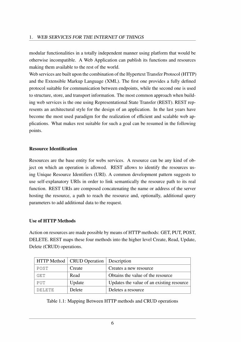
Action on resources are made possible by means of HTTP methods: GET, PUT, POST,DELETE. REST maps these four methods into the higher level Create, Read, Update,Delete (CRUD) operations.
HTTP Method CRUD Operation DescriptionPOST Create Creates a new resourceGET Read Obtains the value of the resourcePUT Update Updates the value of an existing resourceDELETE Delete Deletes a resource
Table 1.1: Mapping Between HTTP methods and CRUD operations
6

1.1 THE WEB AS A DISTRIBUTED APPLICATION PLATFORM
Link Between Resources
The description of a resource can contain a link to other resources. Along with resourcehigh-level description, a client can obtain the URI of other resources, and access themby simply following the provided path. Moreover, the use of URI to describe a resourceallows the linking between resources hosted by different applications or servers.
Resource Representation
Resource representation is usually decoupled from their internal representation. Aserver encodes the resource in a format that can be requested by the client. RESTdoes not provide any restriction on the encoding format of the resource. However, acommon behavior is using standard Internet Media Types. The resource representationis included in the headers server response. Similarly the client can include the acceptedformats in the HTTP request.
Stateless Communication
HTTP connections are stateless. This means that every request is totally independentfrom other requests so that the communication consists only of independent pairs ofrequests and responses. A stateless interaction does not require the server to maintainany session-related information. In fact, if needed, the task of maintaining the stateof the connection is handled by the client. The main advantage of stateless commu-nication is scalability. Firstly, the server don’t have to maintain information related tothe active connections coming from a potential big amount of clients. Secondly us-ing stateless connections facilitates the management of clustered architectures. In factonce the client initiates the communication its requests are not bounded to any sessionretained by the server, and the communication can be moved transparently to otherreplicated servers or functions.
REST interfaces are usually strictly linked to the concept of Application Program-ming Interfaces (API). APIs are a set of functions and procedures to be used as in-terfaces by software components. The use of API has the main role of providing toprogrammers a set of functions that don’t require them neither to know the details ofthe implementation, neither to write their own functions to reach the same scope. Whatwe are doing by making described web service interfaces accessible to programmersis to provide RESTful web APIs.
The success of such a paradigm is under our eyes. Let us consider popular web ap-plications like social networks or cloud storage framework. In addition to provide their
7

1. WEB SERVICES FOR THE INTERNET OF THINGS
own web platform, they also allow developers to access to collected data through webAPI. The possibility to exploit web API to build any kind of application allows thenan unimaginable set of possibilities in regards to content sharing, application mash-upand interoperability.
1.2 Internet of Things
The scenario we described in the previous section can be considered already mature.Computers with apparently no limitations in terms of bandwidth, power consumptionand information processing have built a stable and scalable Internet, able to fit to theneeds of the users. The advent of the Internet of Things (IoT) ( [17] opened a com-pletely new landscape in regards to the possibilities to connect the planet. Not onlypeople, but also any kind of device able to process information can be interconnectedan cooperate in order to build the Future Internet . IoT refers to object that historicallyare not considered to be connected to the Internet:
• electrical devices usually absent from sophisticated electronic
• embedded devices containing electronics components
• non electrical objects like food packages, clothing and so on
• wired and wireless sensors and actuators
The Internet of Things foresee a scenario in which direct interoperability between thebig Internet and the so called things is allowed by means of standardization processaimed to facilitate the communication between these apparently separated worlds. Theamount of interconnected devices is growing day by day. Over the next years thisnumber could grow exponentially, increasing the Internet’s size and capability. How-ever, the communication with small devices and smart objects has to deal with thestrong limitations of these components. Embedded nodes can have limited processingand memorization capabilities due to the costs of production and their reduced dimen-sions. Along with the power constraints comes the need to manage efficiently theirpower consumption, especially when considering wireless sensors. These power andbattery limitations also lead to a networking issue. In order to save resources devicesare sleeping are most of their time, making unfeasible the possibility to reach them assoon as it is needed.
The work in [18] focused the attention on three IoT-related interoperability goalsthat have to be achieved in order to reach its full potential. First of all, an architectural
8

1.3 CONSTRAINED APPLICATION PROTOCOL
reference model have to be outlined in order to enhance the interoperability betweendifferent IoT systems. Secondly, the integration of IoT architecture with the servicelayer is necessary to facilitate the communication and build the future Internet. Thirdly,the IoT networks must be provide with a scalable lookup and discovery of resourcelocation and names.
1.3 Constrained Application Protocol
The IETF has already standardize many protocols to incorporate resource constraineddevices with the Internet. As already mentioned, 6LoWPAN adapts IPv6 to low-powerand lossy networks working on IEEE 802.15.4 wireless standard. RPL provides arouting protocol for IPv6 fluctuating nodes. Efficient XML Interchange (EXI) hasalready been selected by the World Wide Web Consortium (W3C) as the standardXML compression for constrained environments. The Constrained Application Pro-tocol (CoAP) [3] described by Constrained RESTful Environments (CoRE) WorkingGroup is meant to complete this stack in order to provide a complete set of functionspartially solving the aforementioned interoperability issues.
CoAP describes a RESTful client-server architecture for constrained networks. Itimplements a subset of HTTP functionalities, but rather than being a compression ofthis protocol it presents a completely redesigned structure in order to be supported bydevices with limited resources. CoAP works on top of the User Datagram Protocol(UDP). A messaging layer built on top of it provides optional reliability associatingrequests and responses. CoAP sensors are meant to act both as a client and as a server,in order to allow machine-to-machine interaction. Message exchange is based on re-quests made to resource values accessible through Unique Resource Identifier.
1.3.1 Message Format
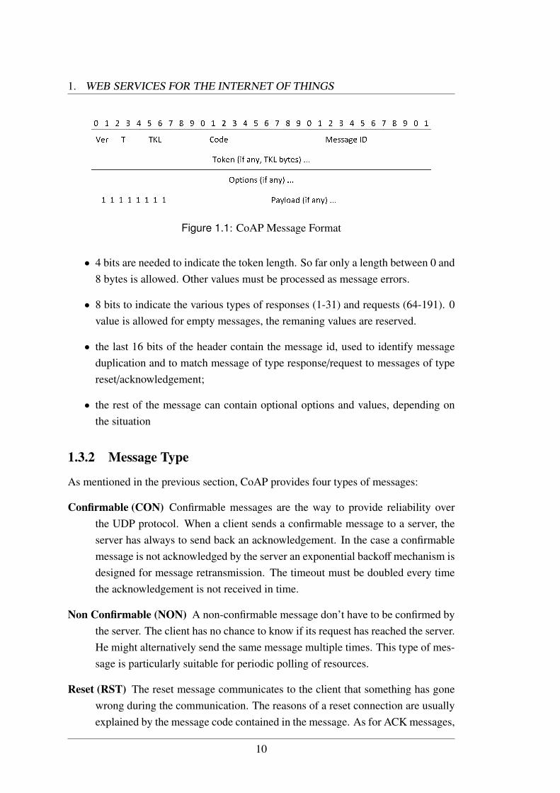
The lightness of CoAP can be noticed first by observing the structure of a CoAP mes-sage (1.1).
CoAP messages are composed by a fixed-length 4-byte header, followed by a seriesof options. The header is constructed by:
• the first two bits indicate the version of the protocol
• the second group of bits indicates the message type: Confirmable (CON), NonConfirmable (NON), reset (RST) and acknowledgement (ACK).
9
1. WEB SERVICES FOR THE INTERNET OF THINGS
Figure 1.1: CoAP Message Format
• 4 bits are needed to indicate the token length. So far only a length between 0 and8 bytes is allowed. Other values must be processed as message errors.
• 8 bits to indicate the various types of responses (1-31) and requests (64-191). 0value is allowed for empty messages, the remaning values are reserved.
• the last 16 bits of the header contain the message id, used to identify messageduplication and to match message of type response/request to messages of typereset/acknowledgement;
• the rest of the message can contain optional options and values, depending onthe situation
1.3.2 Message Type
As mentioned in the previous section, CoAP provides four types of messages:
Confirmable (CON) Confirmable messages are the way to provide reliability overthe UDP protocol. When a client sends a confirmable message to a server, theserver has always to send back an acknowledgement. In the case a confirmablemessage is not acknowledged by the server an exponential backoff mechanism isdesigned for message retransmission. The timeout must be doubled every timethe acknowledgement is not received in time.
Non Confirmable (NON) A non-confirmable message don’t have to be confirmed bythe server. The client has no chance to know if its request has reached the server.He might alternatively send the same message multiple times. This type of mes-sage is particularly suitable for periodic polling of resources.
Reset (RST) The reset message communicates to the client that something has gonewrong during the communication. The reasons of a reset connection are usuallyexplained by the message code contained in the message. As for ACK messages,
10
1.3 CONSTRAINED APPLICATION PROTOCOL
a reset message is associated to the request by means of the message id and mustbe empty.
Acknowledge (ACK) As already said, an acknowledgement have to be sent as a re-sponse of a CON message. In the case the server has to respond with messagecontaining a payload, the ACK can be used to piggy-back the response. In thecase the ACK and the message content are sent separately, we are talking aboutseparate response. Since the message id has to be changed for every retransmis-sion, a separate response is sent using a different one. The client receiving theresponse has to acknowledge it using the new message id. In this case requestand response match thanks to the use of token option.
1.3.3 Request Methods
CoAP inherits the four main HTTP request methods (GET, PUT, POST and DELETE).Every CoAP request is based on the URI of the requested resource and the method usedto access them. Responses are identified by means of status codes. Also in this casethe similarity with http can be noticed.
1.3.4 Options
CoAP options provide additional information to message exchange. They are com-posed of a numeric code, a format and a length. For some of them a default value isprovided. They are divided in two groups: critical (odd code value) and elective (evencode value). The difference stands in the behavior to adopt in the case these optionsare not recognized by the server. An unrecognized critical option makes the server toreset the connection by means of a RST message. On the contrary, an elective optionis simply ignored in the case it’s not recognized properly. Another possible separationis the one between repeatable options and non-repeatable options. Whether a repeat-able option is sent more than once in the same packet the server must treat it as anunrecognized option. We provide now a list of the CoAP options.
Uri-Host, Uri-Port, Uri-Path, Uri-Query
Uri-Host, Uri-Port, Uri-Path and Uri-Query identify univocally the targeted resource.They are separate in such a way that no percent encoding is necessary and the full URIcan be reconstructed easily.
• Uri-Host option identifies the internet name of the host where the resource islocated. It can be either a name or an IP address.
11

1. WEB SERVICES FOR THE INTERNET OF THINGS
• Uri-Port identifies the port on which the requests have to be made
• Uri-Path is a repeatable option containing in order all the components of the pathidentifying the resource in the device.
• Uri-Query allows to specify additional parameters to the resource query
Proxy-Uri, Proxy-Scheme
Proxy-Uri and Proxy-Scheme allow to specify a forward proxy acting as intermediary.The must take precedence on the parameters used to build the target URI, in such away the request is processed correctly by the proxies.
Content-Format
It indicates the content format of the message payload. So far, the acceptable valuesare a subset of the internet media types (also known as MIME).
Accept
Accept is a repeatable option available to clients to specify which content format isacceptable in the response payload.
Max-Age
Max-Age indicates how long the resource can be cached before it’s considered notfresh by the server. This is the basic function used by CoAP protocol to support cachingand save computational resources into the network
ETag
The ETag identifies opaquely a particular representation of a resource. If the serversupports it it’s able to mark every returned value. When the client uses it, the server isable to confirm if the retained resource is still valid without sending its value again.
Location-Path, Location-Query
These options contain the relative URI and a query string. It is used to indicate wherethe resource has been created in response to a POST request. While Location-Path isnon-repeatable, Location-Query can be set multiple times to indicate all the queriesparametrizing the resource.
12
1.3 CONSTRAINED APPLICATION PROTOCOL
If-Match, If-None-Match
If-Match is used for conditional resource request. It can be used with the Etag value orcan be sent without content. In the first case the server responds only if the Etag valuematches with a valid resource, in the second case the condition is satisfied just if thetargeted resource exists. If-None-Match behaves similarly, but carries no value. It isuseful mainly to check if the resource exists and prevents from accidental overrides.
1.3.5 Core Link Format
A key feature for machine-to-machine interaction is resource discovery. Core LinkFormat ( [4]) has been defined to allow this feature in Constrained RESTful environ-ments. Again, HTTP protocol and in particular Web Linking serialization ( [19]) havebeen the start point for the definition of this standard. Resource discovery in Core LinkFormat makes the description of the resources available on the well-known interface./well-known/core of each server. By this way, every server is provided with adefault entry point meant to provide a description of its resources. Every resource isdescribed by means of its Unique Resource Identifier, a set of attributes and, if needed,the relations with the other resources. We underline how the REST paradigm remainsthe key point to access to these lists.
We won’t provide the recursive definition of the Core Link Format in details, welist just some of the parameters provided along with each resource:
Title The title parameter has been inherited by Web Linking, and provides a human-readable description of the resource.
Type The type contains the media type of the returned resource. Only one type pa-rameter per resource is allowed.
Resource Type (rt) This attribute contains a string used to assign an application-specific semantic type to the resource. We can state that while the title is human-readable, the resource type is application-readable.
Interface Description (if) indicates opaquely a specific interface definition.
Maximum Size Estimated (sz) in the case the size of the resource exceed the UDPMTU this attribute can be used to indicate approximately the expected size ofthe response.
13

1. WEB SERVICES FOR THE INTERNET OF THINGS
1.3.6 Observing Resources
CoAP provides a publish/subscribe mechanism [20] where a client can declare to thedevice its interest in receiving updates as the state of the resource changes. An ex-tended GET requests causes the server to register the client in the list of the observersfor the resource. Every notification is an additional response sent by the server in replyto the GET request. Figure 1.2 shows an example of the CoAP observation. It can be
Figure 1.2: Resource observation between CoAP client and server
noticed that:
- the matching between the request and the notifications is made using token op-tion.
- if the request for observation is marked as confirmable the server has to sentconfirmable notification that must be acknowledged by the client. This featureallows the server to establish if the client is still interested in the resource.
The observe value in a response is an indicator used to understand the order ofnotifications. The client has to consider it in order to understand if the last receivednotification is effectively the last one sent by the observed server.
1.3.7 Proxy Operations
The enablement of REST features enhances the communication between CoAP end-points, however the interoperability with the Web reach its completeness only by let-ting devices to communicate easily with HTTP nodes. For this reason, proxy features
14

1.4 WEB OF THINGS
play a fundamental role for the full interoperability of devices with the Web. Generally,the use of intermediaries allows the endpoints to communicate transparently with inter-mediaries that behave like a server on the client side and as a client for the destinationserver. In CoAP environments the intermediaries can simply forward a CoAP requestor perform a cross-protocol translation between CoAP and HTTP. The characteristicsthat CoAP inherits from HTTP make this translation easier. The work in [5] provides aseries of guidelines for consistent and efficient HTTP-CoAP mapping. CoAP methods,status code, content type are all designed in order to provide a straightforward mappingin order to communicate with the Internet.
Independently from the mapping features provided by the proxy, CoAP supportsboth forward-proxies and reverse-proxies, let’s analyze the difference between them.
Forward Proxy a request made through a forward proxy requires the client to indicatethe destination (next-hop) of the request. This is done by means of proxy-uri andproxy-scheme options we listed in section 1.3.4. In this case the client is aware ofthe address of the server and the proxy only needs to rebuild the CoAP messageand to forward it to the received destination.
Reverse Proxy a reverse proxy determines the destination of a request by itself. Aclient interacting with this kind of proxy is not aware of the real endpoint towhich its request is forwarded, and sees the proxy as the server for all its re-quests.
1.4 Web of Things
The IoT has focused on standardizing connectivity in a wide variety of constrainedenvironments. The logical consequence of this evolution is to build high level applica-tions concentrating the efforts on the application layer. RESTful principle has alreadybeen recognized as a de-facto standard for the success, the modularity and the scala-bility of the Web. As mentioned, CoRE concentrated on make things suitable for thisparadigm in order to promote the development of applications involving users, smartthings and the Web. CoAP is the most valuable result of this research.The Web of Things (WoT) [21] considers the IoT as an fundamental component of In-ternet communication and aims to integrate web protocols and technologies to rapidlybuild applications exploiting IoT objects. Solutions such as Axeda1 or AirVantange2,
1http://www.axeda.com/2http://www.sierrawireless.com/airvantage
15
1. WEB SERVICES FOR THE INTERNET OF THINGS
IoBridge3 achieved the goal of connecting things to the Web, but only using proprietarysoftware and interfaces. On the contrary, the WoT vision focuses on sharing systemcapabilities to easily integrate different environments.The community has already experimented an increasing variety of toolkits allowing thevirtualization of networks and providing public access to smart objects through webAPI and simply using a web browser. We list some examples.
Cosm
Cosm [10] is a scalable web platform that connects different types of devices withapplications to provide real-time control, monitoring and data storage. Cosm collectsdevices data and aggregates them in the so called data feed. It provides also open APIfor individuals and companies so that they can rapidly create new devices and interactwith their own products without having to build any infrastructure. Cosm implementsalso triggering and notification functions for real time monitoring of resource values.Moreover, it takes care of the social aspect of the Web of Things. Devices data (datafeeds) can be shared with other users using a smart key sharing system. If no limitationson the access of feeds are required, the device can be also made totally public.
Paraimpu
Paraimpu [13] in highly focused on the integration of physical and virtual sensorsto web and social network. It is built around the concepts of sensor and actuators.A virtual sensor can be associated to one or more actuators able to perform somepredetermined action as soon as a particular predefined condition is met. This can beconsidered an explicit implementation of triggering features provided by Cosm.
Open sen.se
Open sen.se [12] also aims to provide a set of tools for collecting data. Users can mon-itor their data using sense board: a name used to indicate the possibility of visualizedata on a board containing the output of various sensors. Data are collected though theuse of channels (physical devices, web forms, generic connected data sources) whilethe processing is managed by internal applications. A key feature confirming the needof interoperability in the WoT is underline by the fact that open sen.se explicit refersto Cosm data feeds as a possible source for data collection.
3http://www.iobridge.com/
16

1.4 WEB OF THINGS
Wotkit
WotKit [22] is born as a response to developers that already have to deal with widerange of API provided by as many IoT toolkits. Besides providing an implementationof a monitoring framework for the Web of Things, the work in WotKit is aimed to pointout a series of requirements and open questions to be taken into consideration whendeveloping in the WoT world.
Nimbits
Nimbits [11] allows to register and process historical values from multiple resources.It can be used as a backend infrastructure for applications, taking care of managing,storing and processing data collected from different applications. Data collection is notbounded to the use of devices, but provides an interface for applications to push the socalled nimbits data point into the system.
17

1. WEB SERVICES FOR THE INTERNET OF THINGS
18

Chapter 2
Requirements Analysis
In this section we provide a brief description of system functionalities and require-ments, along with the tools we used to develop it. A detailed description of the appli-cation is provided in chapter 3.
We aim to develop a web service allowing users to connect to REST-enabled CoAPdevices and manage them transparently through the web. No user interface has beendeveloped. Rather than providing a user interface we primarily focused on providingREST interfaces upon which any kind of application can be built. To make use of sys-tem features and to obtain access permissions, users have to use an application whichhas previously been registered by developers. Thanks to REST interfaces developersare able to interact with sensor networks, collecting data, instruct the web service topush notifications if some predefined conditions are met. Every device, resource orservice can be identified by a Unique Resource Identifier accessible via HTTP meth-ods (GET, POST, PUT and DELETE). Thanks to this approach, users and developersdon’t have to be aware on the technical details regarding network implementation butwill interact with virtualized instances of devices.
The use of a database along with the virtualization of resources is especially meantto lighten the workload of constrained networks we’re dealing with. Besides providingbasic storage features of historical data and devices information, the web service mustbe also able to cache resource values. In this case a request must be forwarded to thedevices only if the previously obtained resource values are considered not fresh.
The whole application must have two entry points. On one side it responds to userrequests performed by means of registered applications. On the other side it has tointeract with CoAP sensor networks by both sending requests and receiving data asyn-
19

2. REQUIREMENTS ANALYSIS
chronously. Received values and devices information have to be stored in a database.We underline how in the last case the resources values are obtained both as a responseof a request or as a notification initiated by the observed resource. The dynamic natureof sensor networks encouraged us to take into consideration the possibility to scalesystem resources in order to face unpredictable computational demand. We want tomake sure that improvised workloads caused by the sensor networks don’t affect theperformances in terms of responsiveness. These aspects leads to the need of build ascalable infrastructure in which system components able to cooperate with each otherwithout creating conflicts.
We provide now a short list describing briefly the typical use case flow.
• developers can register their application. The registration allows them to receivea key-pair through which the system identifies the origin of the generated traffic.All the APIs (apart from the ones used for asynchronous notifications) require auser token which can be obtained only by means of registered resources.
• a user logs in into the system using its login and password, obtaining an accesstoken. The access token is necessary to perform all the basic operations.
• a user registers its devices, specifying their address, the optional intermediariesand other human-readable information, like names and tags. A user owns thedevices he registers using our application. Unless he decides to share them, theinformation related to these devices remains accessible only using user creden-tials.
• a user registers the resources associated with the device. This must be donemanually via API or by instructing the server to query the Core Link Formatdescription (see section 1.3.5) to the device.
• the user must be able to instruct the application to poll devices periodically, orto register to CoAP devices as observer (see 1.3.6).
• all the values received from a remote device must be stored persistently andprocessed. The user is able to set trigger conditions upon which different typesof notification can be sent as soon as the new value is stored into the database.
20

2.2 REQUIREMENTS
2.1 Requirements
Given the above consideration we resume technical requirements to consider in thedefinition of the system architecture.
• Queuing Requests. We will describe how the application is built upon compo-nents deployed in different servers. These component are constantly exchangingrequests between them. We must ensure that all the messages are queued andhandled properly avoiding requests to be lost due to inefficient management ofmulti-threading and queuing mechanism.
• Scalability and concurrency. Different instances of the same application mustcooperate without interfere with each other. Both database transaction and con-nections to device must be atomic and isolated.
• Easy Deployment. The application components must be easy to deploy. Theneed to deal with a scalable architecture require components to run out of the boxwithout needing any instance specific information and without complex config-uration settings.
• Asynchronous Communication. The potential amount of simultaneous con-nections could downgrade servers’ performances. When possible an asynchronouspublish/subscribe mechanism can free machine resources and enhancing respon-siveness.
2.2 Used Tools
The core components of the framework are Java web application leveraging severaladditional tools and libraries. In this section we describe the main ones.
2.2.1 Spring Framework
Spring Framework is an enterprise Java programming framework that provides a setof functionalities to easily develop any kind of java application. Although it’s suitableeven for stand-alone applications it’s well known in the community as an excellent toolfor developing web services.There are mainly two functionalities of Spring that made it appropriate for the devel-opment of our application: RESTful Model and View Controllers (MVC) and depen-dency injection.
21

2. REQUIREMENTS ANALYSIS
Model and View controller is an architecture pattern whose main idea behind is toseparate the software components:
• Model. The model supply the methods to access to application data
• View. The view is responsible for displaying the information to the users
• Controller. The controller receives the requests forwarding them to the view,the controller or both
The idea behind the Dependency Injection is to have an external component (as-sembler) which takes care of creating objects and their dependencies and to link themthrough the use of injection. The injection can be done using a constructor or a settermethod and allows to decouple the creation of the object from the creation of its de-pendencies. Spring provides dependency injection features through the use of beansand annotations.
The Spring DispatcherServlet receives HTTP requests and forwards themto the controllers. The association between the request and the controller method thatwill handle the request is made through the RequestMapping annotation. All thesemappings are straightforward so that every request can be mapped in a unique con-troller method. At this point the controller parses the needed HTTP parameters andforwards them to the service layer. A Spring service owns the business logic of theapplication. Apart from performing the most power demanding operation it can beviewed as a forwarding point handling information exchange between the controllers(acting as interfaces for external applications) and data management classes. The de-pendencies between these three layers is handled using dependency injection. Figure
Figure 2.1: An example of HTTP URL that can be handled by a controller
2.1 illustrates an example of URL handled by the DispatcherServlet. The context stringidentifies the servlet that has to handle the requests. After the servlet has been calledthe control is passed to the RequestMapper that will find the proper associationbetween the pattern and the controller which is responsible for it. The controller inlisting 2.1 is an example of a controller suitable to satisfy this request.
22

2.2 USED TOOLS
Listing 2.1: An example of a Spring controller with an auto-wired dependency1 @RequestMapping("/coap")
final class ResourceController{
3
@Autowired
5 AuthenticationService authenticationService;
7 @RequestMapping(method=RequestMethod.GET, value = "/{device}/{
resource}")
@ResponseStatus(value = HttpStatus.OK)
9 @ResponseBody
public DataEntryDTO getLastValue(@RequestHeader(value="UserKey",
required=false) String key,
11 @PathVariable String device, @PathVariable String resource){
13 User user = authenticationService.authenticate(key);
15 DataEntryDTO dt = rService.getUpdatedResource(device, resource,
user);
return dt;
17 }
}
• Autowired is the annotation needed to inject the service dependency into thecontroller. No constructor is needed: the controller can use the service as soonas its methods are called by the DispatcherServlet.
• RequestMapping tag on the top of a Controller class is used to map everyrequest starting with /coap while the same annotation upon the method com-pletes the mapping. By this way every HTTP GET request on the URL showedin figure 2.1 will be handled by the method.
• the ResponseStatus defines the HTTP response status to return to the clientif the request and its processing have been performed correctly.
• ResponseBody is the core of the View part. In fact, it allows the server toautomatically bind every response object into the format requested by the clientin the Accept HTTP header.
• RequestHeader parses the HTTP header looking for the one with key UserKey.
• PathVariable maps the variables into the controller path into the parametersof the method.
23

2. REQUIREMENTS ANALYSIS
Controllers are only the surface of the whole processing engine that stands behind theweb application. Section 3 will provide a description of the back-end functionalitieshandled by auto-wired services.
2.2.2 Hibernate
Hibernate is an Object/Relational persistence and query service taking care of mappingJava classes into relational database tables. Moreover it provides several facilities toaccess to database at different level of abstraction, from the plain SQL query to thehigh level and powerful Criteria object. The usage of a query system with respect toanother depends on the needed level of performance and complexity.Hibernate integrates perfectly with the Data Access Object (DAO) design pattern. Theidea behind DAO pattern is to decouple object persistence and data access logic. Theinterface provided by a DAO doesn’t depend neither on the implementation of thedatabase nor on the query system, allowing the developer to change the persistencemechanism without the need to re-engineer the application logic.
Figure 2.2: Hibernate work schema combined with DAO data access pattern
Moreover, combining Hibernate and Spring functionalities it’s possible to defineeasily the isolation level of single java methods. Exploiting these features properlyhelps in transferring the required isolation to well defined part of Java server code.
2.2.3 Quartz
Quartz Enterprise Job Scheduler is generally used for complex scheduling in Javaapplications. In respect to Java Timer Tasks, Quartz presents several advantages, let’slook at the main ones:
Cron Expressions Job scheduling can be defined using the powerful Unix cron syn-tax. In particular, CronTrigger objects can be programmed to be fired at
24

2.2 USED TOOLS
specific dates and time. Using this capability it’s possible to schedule actions ina more complex way in respect to simple periodic scheduling, allowing expres-sions like every monday at 8am or every working day every 10 minutes.
Task Persistency Periodic tasks can be made persistent thanks to the use of JDBCJobStoremodule. JDBCJobStore works with nearly every database and is able to storethere all the scheduling information. This means that even if the applicationcrashes or needs a reboot, the information related to the already scheduled jobswon’t be lost.
Clustering Support Quartz can be used in clustered environments. Combining it withJDBCJobStore it handles automatically the concurrency between the differentinstances of the cluster, in such a way that every job is fired only once whenneeded.
The combination of these three features allows the system to schedule new jobs dy-namically, storing them on a persistent storage while making them available to all theinstances of a replicated service.
2.2.4 jCoAP
jCoAP is a Java library implementing many CoAP functionalities. Its implementationis not suitable for constrained devices but fits well for the integration with Java basedweb services and platforms such as smartphones (e.g. Android). jCoAP has beendeveloped in the University of Rockstock and sponsored by Siemens Corporate Tech-nologies. Though its development is still since almost one year it is the most completeJava library for the scope. Apart from client and server implementations, jCoAP pro-vides also CoAP-HTTP and HTTP-CoAP proxying features. In this thesis we madeuse of a modified version of jCoAP client and and jCoAP server. The reason why wedidn’t take advantage of the proxy implementation are explained in the next sections.
25

2. REQUIREMENTS ANALYSIS
26

Chapter 3
System Architecture and Development
In this section we illustrate the features of our web service with regards to softwaredevelopment and network architecture. We describe a flexible and scalable frameworkwhich aims both to manage efficiently large amounts of sensors and to provide highlevel interface virtualization for end users to access transparently to the informationgathered from the devices. We aimed to make the infrastructure suitable for develop-ers. The application implements REST-style architecture over HTTP. All the entitiesand the functionalities of the system are identified by a persistent Uniform ResourceIdentifier, while every request and response is formatted using XML or JSON. Theapplication implements some of the typical functionalities required when managingsensor networks. We will describe in details how the system is able to manage event-driven notification, task scheduling and query aggregation.
3.1 Overview
3.1.1 Involved actors
Before describing the architecture in detail we provide a brief overview on the actorsinvolved in the communication process.The web service can be queried by an HTTP client. The client can be any type of appli-cation built upon public API provided by the RESTful server. The RESTful server pro-vides the public access to all system functionalities. It receives REST requests from theclients, accesses to the database, manages computational demanding operations. It canbe instructed to query the devices either using its own embedded CoAP client or for-warding all the requests to the independent data module. Devices can be reached boththrough a CoAP Gateway or through a transparent HTTP proxy. A MySQL databaseallows the RESTful server to store all relevant information, from devices information,
27

3. SYSTEM ARCHITECTURE AND DEVELOPMENT
to trigger values up to the historical information obtained by resources. Figure 3.1shows the complete scenario.
Figure 3.1: Network structure
3.1.2 Virtualized Entities
Making the IoT available to end users forcedly takes us to the concept of virtualiza-tion. Virtualizing wireless sensor network is meant to provide an abstraction layerhiding technical implementation details to end-users. Though by now it’s not our case,it’s particularly suited for framework supporting networks and protocols of differentnature. Virtualization provides the same interface independently on which kind of sen-sor is hidden behind. We provide here a description of the virtualized entities uponwhich the framework is built.
Physical devices are the entity related to all the information needed to reach theCoAP sensor through the internet. The IP address, the listening UDP port, MAC ad-dress and the owner are set during device registration allowing the web service toredirect request to the proper end point.
CoAP sensor cannot always be queried directly. Facing the need of interoperability,the Internet of Things has to deal with intermediaries able to translate the traffic from
28

3.2 ARCHITECTURE MODULES
one protocol to another. Moreover, though IPv6 is mature enough for addressing sen-sor networks and devices, IPv4 networks and their NAT-related drawbacks still have tobe considered. For these reasons one or more CoAP gateways can be associated witha physical device. The web service makes use of CoAP proxy features to build CoAPpackets using Proxy-Uri option and to address the packets properly in both the cases.
Physical devices don’t provide the needed abstraction level to reach our scope. Ahigher level access point to devices is provided by logical devices. A logical deviceis identified by a unique numeric identifier and supply additional information like asensor name, a description and tags, allowing to identify nodes in a human readablemanner. A logical device represents an abstraction of a physical device: its represen-tation has the goal of making the access to resources as transparent as possible. Aphysical device can be associate to one or more logical devices during its ’virtual’ life-cycle. However, this can be possible only for one logical device at time. This feature ismeant to face the situation where a physical CoAP mote changes its location or scope.In this case the system behaves as another sensor had been created and the physicaldevice is linked to a new logical one. Data can then be collected using the new logicaldevice while still keeping frozen the information related to the previously unlinked one.
The creation of a logical device finally allows to instantiate virtual resources. EveryCoAP device provides the access to its sensors through the paths that identify them.Even if it is virtualized the framework keeps a resource accessible explicitly by usingits CoAP path (see section 3.3). Once the device has been reached the resource ismade available through the four familiar HTTP methods applied to the resource path.As described in section 1.3.5, the Core-Link format is suitable for REST enabled sen-sor networks to allow resource discovery in M2M application. This feature can beexploited by the user and the framework will be able to parse all the public resourcesmade available using a GET to ./well-known/core resource path on CoAP well-known port. In the case resources are not public, or simply the CoAP server don’timplement resource discovery features, it’s possible to insert all the resources manu-ally.
3.2 Architecture Modules
The functionalities of the framework can be divided in three distinct modules: theaccess module, the processing module and the communication module. The accessmodule provides the interfaces and the data access to the virtual instances of the de-
29

3. SYSTEM ARCHITECTURE AND DEVELOPMENT
vices, the processing module elaborates the information and manages scheduling, noti-fication, triggering and data elaboration, the communication module is responsible fordirect communication with the CoAP networks. Figure 3.2 summarizes the functionsof the modules.
Figure 3.2: Schema of the application modules and functions
3.2.1 Access Module
The access module is mainly handled by means of Spring controllers. In section 2.2.1we describe how controllers are the entry point to access to all the functionalities ofthe application and are then responsible for passing the correct information to the othermodules. Part of the their customization has already been treated, however we list herethe pre-processing and the post-processing operations performed by each controller.
• validating the received XML inputs
• parsing incoming HTTP parameters into predefined java classes
• binding outgoing requests into the format indicated in the HTTP Accept param-eter, which can be either XML or JSON
• handling runtime exceptions and translates them into a defined HTTP status code
30
3.2 ARCHITECTURE MODULES
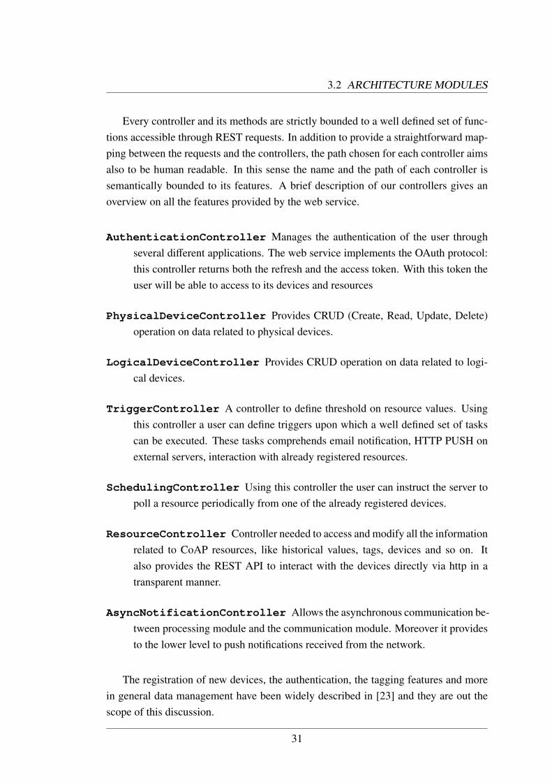
Every controller and its methods are strictly bounded to a well defined set of func-tions accessible through REST requests. In addition to provide a straightforward map-ping between the requests and the controllers, the path chosen for each controller aimsalso to be human readable. In this sense the name and the path of each controller issemantically bounded to its features. A brief description of our controllers gives anoverview on all the features provided by the web service.
AuthenticationController Manages the authentication of the user throughseveral different applications. The web service implements the OAuth protocol:this controller returns both the refresh and the access token. With this token theuser will be able to access to its devices and resources
PhysicalDeviceController Provides CRUD (Create, Read, Update, Delete)operation on data related to physical devices.
LogicalDeviceController Provides CRUD operation on data related to logi-cal devices.
TriggerController A controller to define threshold on resource values. Usingthis controller a user can define triggers upon which a well defined set of taskscan be executed. These tasks comprehends email notification, HTTP PUSH onexternal servers, interaction with already registered resources.
SchedulingController Using this controller the user can instruct the server topoll a resource periodically from one of the already registered devices.
ResourceController Controller needed to access and modify all the informationrelated to CoAP resources, like historical values, tags, devices and so on. Italso provides the REST API to interact with the devices directly via http in atransparent manner.
AsyncNotificationController Allows the asynchronous communication be-tween processing module and the communication module. Moreover it providesto the lower level to push notifications received from the network.
The registration of new devices, the authentication, the tagging features and morein general data management have been widely described in [23] and they are out thescope of this discussion.
31

3. SYSTEM ARCHITECTURE AND DEVELOPMENT
3.2.2 Processing Module
Processing module contains the core functionalities of the entire application. Apartfrom handling the communication between the other two modules he’s also responsiblefor database access through DAO objects. Figure 3.3 illustrates the behavior of thismodule.
Figure 3.3: Behavior of processing module when querying and receiving new resourcevalues
Spring services are responsible for managing the flow showed in the figure. Againwe’re dealing with Java classes with different separate goals. Since the task separationis very similar to the one listed in the previous section we won’t describe all the de-veloped services. Still, we have to focus the attention only on the one responsible forexternal communication: ResourceService.ResourceService manages the access to both virtual and physical resources. It isused to recover resource information, historical values and to interact with the com-munication module in order to obtain an updated resource value. Notification mod-ule and data handler are nothing more than functions called by ResourceServicewhen needed. These methods inherit the generic behavior of services in accessing thedatabase through DAO objects. On the other hand quartz scheduler and jobs behavesdifferently. While the request for a new job has forcedly to make use of controller andservices, the access to the database is handled autonomously by quartz library.All the outgoing requests for the communication module are queued and consumed bymeans of a thread pool, in particular using Java ThreadPoolExecutor. A request
32

3.2 ARCHITECTURE MODULES
is intended to be a task to be executed by one of the threads handled by the thread pool.The parameter to construct this object explains the implied advantages:
Core Pool Size is the number of threads that are always available in the pool of threads
Maximum Pool Size is the maximum number of threads to allow in the pool
Keep Alive Time if the number of threads is greater than the core pool size the threadremains available even after having terminated its tasks. This allows the threadpool to reuse it for future tasks without instantiating new tasks.
Working Queue is the queue used to hold tasks before they are executed.
In short, a thread pool allows the application to queue the requests and handle themexploiting the multi-threading paradigm. In addition to provide an high level queuingsystem it also helps to avoid the exhaustion of the thread pool handled by the servletcontainer. Other feature of thread pools, like rejection handler and dynamic variationof the parameters have to be investigate to enhance even more performance and re-source scaling.
Outgoing messages can be both synchronous or asynchronous, depending on thesource of the request. In the following sections we will investigate these use cases.
3.2.3 Communication Module
In a preliminary development phase the communication features were handled by theprocessing module. In this sense the service processing module and the communica-tion module resided on the same physical (or virtual) machine. Although this approachreduces latency and seems to improve performances it ends up presenting several draw-backs.
First of all, hard coded integration of a CoAP client within the server code strictlylinks the entire application to a unique CoAP implementation. Though jCoAP fitsproperly around the need of developing a complex distributed Java application, it isonly one of the known implementations of this protocol. Good surveys of CoAP andpurposed implementations have been provided in [24] and [25]. Thus, looking at theoption of adopting other CoAP implementation in the future forced us to enhance theflexibility of the system.
33

3. SYSTEM ARCHITECTURE AND DEVELOPMENT
Secondly, a CoAP response can take seconds or even minutes to reach the requestserver. CoAP defines simple message layer for providing a reliable connection ontop of UDP protocol. The comparison in [25] confirms considerably performance im-provements with regards to HTTP. However, the need for the web service to managehundreds of connections simultaneously take us back to performance consideration.Retransmission is based on two parameters: the maximum number of retransmissionand the timeout value. The timeout value is doubled every time a retransmission isneeded. As a matter of facts, using default values indicated in table 3.1 the time fromthe first transmission of a CON packet and the time when the client gives up acceptingacknowledgements (the so called MAX TRANSMIT WAIT) is 93 seconds.
Name Default ValueACK TIMEOUT 2 secondsACK RANDOM FACTOR 1.5MAX RETRANSMIT 4
Table 3.1: CoAP Default Transmission Parameters
Thirdly, transparent HTTP-CoAP mapping and vice versa is still under investiga-tion. We don’t want to exclude a possibility of transforming our module in a simple andefficient implementation of a transparent proxy. However there are still some issues toface in order to reach this goal. As well as HTTP, CoAP don’t provide multi-hop proxyfeatures. Thus seeing the communication as a simple mapping of an HTTP request intoa CoAP message collides with the need of transmitting explicitly the intermediary fromthe processing module to the communication module.
These considerations led us to the development of a completely independent mod-ule managing communication with external networks. For now the communicationmodule is another web application leveraging the Spring framework and receiving in-puts through HTTP requests. In respect to the rest of the application the communica-tion module is only responsible to translate internal requests into CoAP messages tobe delivered externally. Figure 3.5 summarizes this behavior in the simplest case.
A very important advantage of choosing a network protocol for information ex-change between modules is that they can be decoupled and deployed in different physi-cal (or virtual) machines. In a situation in which a lot of connections have to be handledsimultaneously the possibility to replicate the network modules significantly reduce theworkload of the processing modules. Performances can be improved even more if we
34

3.3 ACCESS TO RESOURCES
Figure 3.4: Synchronous communication between modules
consider the possibilities for the two components to communicate asynchronously. Afire-and-forget scenario becomes then suitable for the machines receiving user requestsand processing data. Figure 3.5 illustrates this situation.
Figure 3.5: Asynchronous communication between modules
We are aware that HTTP is not meant for asynchronous message exchange. Otherasynchronous protocol like Java Message Service (JMS) [26] or the AsynchronousMessage Queuing Protocol (AMQP) [27] will be considered for this use. On the otherhand the possibilities to lighten the communication through the implementation of acustom efficient proxy are not to be excluded.
3.3 Access to Resources
Our web service provides REST access to all the functionalities and resources de-scribed in the previous section. In this section we concentrate the description on the
35
3. SYSTEM ARCHITECTURE AND DEVELOPMENT
access to virtual instances of physical devices, logical devices and resources.
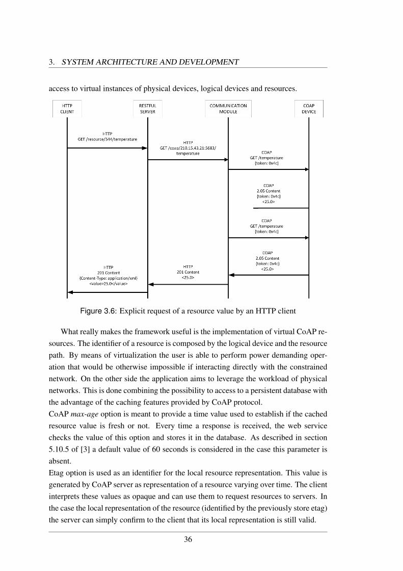
Figure 3.6: Explicit request of a resource value by an HTTP client
What really makes the framework useful is the implementation of virtual CoAP re-sources. The identifier of a resource is composed by the logical device and the resourcepath. By means of virtualization the user is able to perform power demanding oper-ation that would be otherwise impossible if interacting directly with the constrainednetwork. On the other side the application aims to leverage the workload of physicalnetworks. This is done combining the possibility to access to a persistent database withthe advantage of the caching features provided by CoAP protocol.CoAP max-age option is meant to provide a time value used to establish if the cachedresource value is fresh or not. Every time a response is received, the web servicechecks the value of this option and stores it in the database. As described in section5.10.5 of [3] a default value of 60 seconds is considered in the case this parameter isabsent.Etag option is used as an identifier for the local resource representation. This value isgenerated by CoAP server as representation of a resource varying over time. The clientinterprets these values as opaque and can use them to request resources to servers. Inthe case the local representation of the resource (identified by the previously store etag)the server can simply confirm to the client that its local representation is still valid.
36
3.4 RESOURCE MONITORING
Image 3.6 is only one of the scenarios where the web service receives a new value.This particular situation is the one requiring more efforts on the server side, due to theneed of maintaining open several TCP connections. Further cases will be investigatedlater on in this chapter.
3.4 Resource Monitoring
Monitoring WSNs is key point for web enabled sensor framework. One of the openquestions arose in [22] encourages the community to reason out on the implication ofpolling data periodically rather than waiting for the data to be sent by the sensors. Thefirst approach reveals itself to be very expensive for constrained environments: sensorcould be in sleeping mode for most of the time, the state of the resource could not havebeen changed over time. These situations cause useless traffic to be generated both onthe client and server side. In the second case the device could find obstacles in reachingthe observer application without having being queried before.
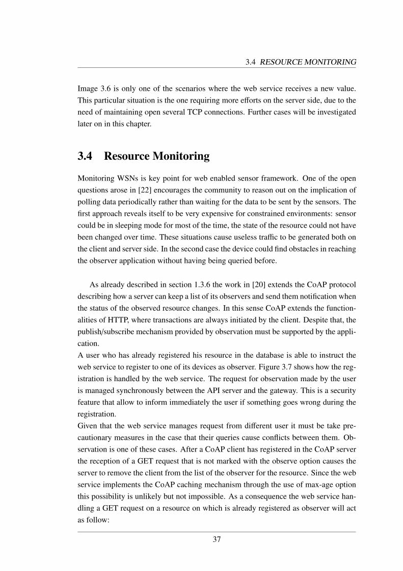
As already described in section 1.3.6 the work in [20] extends the CoAP protocoldescribing how a server can keep a list of its observers and send them notification whenthe status of the observed resource changes. In this sense CoAP extends the function-alities of HTTP, where transactions are always initiated by the client. Despite that, thepublish/subscribe mechanism provided by observation must be supported by the appli-cation.A user who has already registered his resource in the database is able to instruct theweb service to register to one of its devices as observer. Figure 3.7 shows how the reg-istration is handled by the web service. The request for observation made by the useris managed synchronously between the API server and the gateway. This is a securityfeature that allow to inform immediately the user if something goes wrong during theregistration.Given that the web service manages request from different user it must be take pre-cautionary measures in the case that their queries cause conflicts between them. Ob-servation is one of these cases. After a CoAP client has registered in the CoAP serverthe reception of a GET request that is not marked with the observe option causes theserver to remove the client from the list of the observer for the resource. Since the webservice implements the CoAP caching mechanism through the use of max-age optionthis possibility is unlikely but not impossible. As a consequence the web service han-dling a GET request on a resource on which is already registered as observer will actas follow:
37
3. SYSTEM ARCHITECTURE AND DEVELOPMENT
Figure 3.7: Resource observation handled by the web service
- if the resource value has expired a new observe request is sent to the server
- if the resource value stored in the database is still valid no requests will be sentto the server and the returned value will be the cached one
Observe option is not a mandatory feature to implement in a CoAP device. Thesituation in which the device refused observation requests must be taken into account.Moreover there could be cases in which notify every single change of state of the re-source is unnecessary. For these reasons our implementation support periodic pollingof device resources. The user is able to dynamically schedule new complex periodictasks responsible for polling resource values.
As mentioned in section 2.2.3 Quartz Scheduler provides the necessary tools toaccomplish this task. Quartz allows to schedule tasks dynamically and to make thempersistent due to the integration with several database implementations.Quartz scheduling is based on the association between jobs and trigger. A job is aninterface to be implemented by java classes that have to be executed by one of theworker thread of the main scheduler. A trigger contains the time condition upon whichthe associated job has to be executed. Quartz provides two kinds of triggers:
Simple Trigger Simple triggers are used when the task has to be executed once at a
38

3.5 TRIGGERING RESOURCE VALUES
specific time or to be executed repeatedly at a specific interval after a given startmoment. For example, with a simple trigger it’s possible to schedule a job toexecute for the first time the 1st of January, then every 7 days.
CronTrigger CronTrigger is useful for more complex scheduling based on calendar-like notions. As mentioned in chapter 2.2.3 triggers are defined using a Unix-likecron syntax. A cron trigger, for example, can be instructed to be fired every 5minutes from 8am to 12am only during working days.
Our web service allows users to request this kind of schedules using REST API. Figure3.8 illustrates this process.
A post request destined to the SchedulingController is sent through an HTTP POSTrequest. The information required by the application for registering a new trigger is thefollowing:
• the period of the scheduler, if only a simple schedule is needed
• the cron expression as a possible alternative to the simple trigger period
• the resource URI
• the CoAP method (GET, PUT, POST, DELETE)
• the value to send in case of a PUT or a POST request
Upon the reception of this request the controller forwards it to the SchedulingServicewhich will instantiate the new job. The job persistence is handled by Quartz in a to-tally transparent manner. This means that the service takes care only about schedulingthe new job without interacting directly with the database. From this moment everyinstance of the web server connected to the database will be able to run this job, whileconcurrency is again handled by quartz.
3.5 Triggering Resource Values
Collecting values from multiple resources, located in different networks around theplanet is a basic feature for an application integrated with wireless sensor network.However this is not enough. The potential huge amount of information collected bysuch a platform requires also processing capabilities that could be otherwise impossi-ble due to the constrained nature of the devices.
39

3. SYSTEM ARCHITECTURE AND DEVELOPMENT
Triggering resource values in an example. An application is required to be able toprocess received data as soon as they are received. The importance of this feature isundeniable. Cosm triggers [10], Nimbits events subscription [11], Paraimpu [13] ac-tuators, Open Sen.se [12] notifiers are only some of the examples of how applicationsproviding triggering features for their users.
Our application does the same. Every value received upon a CoAP observe notifi-cation, a user request, a periodic scheduler is handled by a data module that:
- validates the incoming values
- push notifications in the notification queue handled by a thread pool.
As for scheduled jobs the user can create triggers using the API handled by the TriggerController. The functionalities are inspired by the ones provided by the frameworklisted above. The request is based again on an XML (or JSON) message in which theuser can indicate a list of conditions and a list of actions to accomplish whether all theconditions are verified. The allowed actions up to now are:
- send an email to the creator of the trigger
- GET, PUT, POST, DELETE request made to another resource owned by thecreator of the trigger
- POST action on a URL given by the creator
Listing 3.1: An example of XML request to set a trigger on a resource value<?xml version="1.0" encoding="UTF-8"?>
2 <trigger><name>Heater Trigger</name>
4 <conditionList><condition>
6 <comparator>lt</comparator><value>18.0</value>
8 </condition></conditionList>
10 <actionList><action>
12 <type>email</type></action>
14 <action><type>put</type>
16 <target>/34/heater<target><value>ON</value>
18 </action></actionList>
20 </trigger>
40

3.5 TRIGGERING RESOURCE VALUES
Listing 3.1 shows a trigger creation message. This message must be sent using theURI identifying all the triggers of the given resource. For example, the above messageposted to URI /trigger/54321/temperature can be translated in if the temperature goesbelow 18.0 degrees switch the heater on and send me an email. Trigger fire when thecondition is met, while the received value are respecting the threshold no more actionare done.
Figure 3.8: Behavior of the system in response to a registration of a periodic task
The list of conditions received in XML format are mapped into strings suitable tobe converted in a Boolean value through the use of Apache JEXL1. Triggers associatedto a resource are checked every time a resource value is received. JEXL allows to avoidthe use of multiple database lines and tables to store a complex condition enhancingthe performances of such a frequent operation.
1http://commons.apache.org/proper/commons-jexl/
41

3. SYSTEM ARCHITECTURE AND DEVELOPMENT
42

Chapter 4
Tests and Results
In this section we will analyze the performances of the application in terms of re-sponsiveness and communication overhead considering the variations of different pa-rameters. All the tests have been performed in a simulated environment composed ofdifferent Linux machines acting as clients, devices, server or deploying the commu-nication module. We underline how we will consider only the processes involving adirect communication with devices.
4.1 Testing Tools
The components of the simulated environment have been deployed in 5 different phys-ical machines in a Wireless Local Area Network (WLAN). As mentioned, dependingon the component we used different programming languages and computers. Table 4.1illustrates the main characteristics of the components.
Role Language OS CPUClient 1 Python Ubuntu 10.04 Intel Core 2 Duo T7300Client 2 Python Ubuntu 12.04 Intel Core 2 Duo T7300Core Server Java (Tomcat) Ubuntu 12.04 Intel Core i7-3630QMComm. Module Java (Tomcat) Ubuntu 10.04 AMD Athlon 64 X2 Dual
Core 5400+
Devices Java (jCoAP) Ubuntu 12.04 Intel Core i3-2370M
Table 4.1: Used machines in the simulated environment
43
4. TESTS AND RESULTS
Client
To utilize the web application functionalities we developed some python scripts. Inorder to exploit as much as possible the CPU power these programs have a strongmultithreaded behavior and have been developed in order to change dynamically theirexecution speed. The frequency of requests, the set of resources to query, the intervalbetween two subsequent requests and the number of thread to use during tests can beset as input parameters. More precisely, we programmed these clients to accomplishthese tasks:
• querying resources to the web service
• schedule new jobs in such a way that after the first query are processed au-tonomously
• simulating a flood of notifications on the device side
Devices
Devices have been simulated using again jCoAP library (see 2.2.4). In order to re-flect the behavior of real sensors in terms of communication and processing delay wehave modified the purposed default implementation in such a way to be able to setdynamically a normal delay and the loss rate of the responses. Both these variables aregenerated using the Random class provided by Java API.
Web Service
The web service has been deployed in two different machines. The first one leveragespublic APIs, database interaction, notification and processing, the second one acts ascommunication module in order to forward the requests to the proper endpoints. Boththe applications have been deployed using Tomcat application server.
Performances have been evaluated through the use of TCPdump1 for sniffing thetraffic passing through the core server. By this way we were able to intercept all re-quests and responses as soon as they reach or leave server network interfaces. Wire-shark2 has then been used to format the data in a way suitable to be parsed and ana-lyzed.
1http://www.tcpdump.org/2http://www.wireshark.org/
44

4.3 PERFORMANCE ANALYSIS
4.2 Performance Analysis
We now illustrate the performances related to the operations described in chapter 3.We tested the system paying particular attention in choosing the most power demand-ing operation depending on the described situations. As an example, all messagesexchanged with devices are of type confirmable (see section 1.3.2) in such a way thatthe proxy has to deal with several open UDP connections at the same time. Due to thewide variety of involved components we have chosen some parameters to vary in orderto simulate as precisely as possible real use case situations.
The variables we considered are:
• the number of client requests per seconds
• the caching time of a value received from a device
• the average delay to receive a response from the devices
• the loss rate of a single CoAP response
• the number of resources to query
4.3 Synchronous Resource Request
In section 3.3 we already raised the problem of handling these types of connection.Since clients require and wait for a response, all the connections must be handledsynchronously. For these reasons many open TCP connections can smoothly degradesystem performances, especially without the help of cached values. In fact, the numberof resources in this case is so high that the probability to query a resource twice in thesame minute is very low. The following scenario illustrates this behavior.
Resources 100.000Mean Delay 1500 msStandard Deviation 500msLoss Rate 10%Caching Time 60 seconds
Table 4.2: Used parameters for testing synchronous communication
In figure 4.1a we illustrate the behavior of the service receiving 29962 requests in2050 seconds (34 minutes). The average number of requests per second in the long run
45
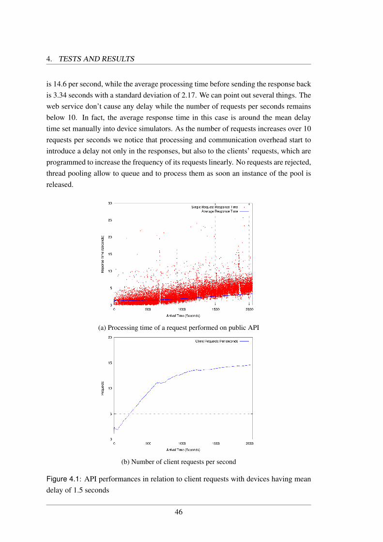
4. TESTS AND RESULTS
is 14.6 per second, while the average processing time before sending the response backis 3.34 seconds with a standard deviation of 2.17. We can point out several things. Theweb service don’t cause any delay while the number of requests per seconds remainsbelow 10. In fact, the average response time in this case is around the mean delaytime set manually into device simulators. As the number of requests increases over 10requests per seconds we notice that processing and communication overhead start tointroduce a delay not only in the responses, but also to the clients’ requests, which areprogrammed to increase the frequency of its requests linearly. No requests are rejected,thread pooling allow to queue and to process them as soon an instance of the pool isreleased.
(a) Processing time of a request performed on public API
(b) Number of client requests per second
Figure 4.1: API performances in relation to client requests with devices having meandelay of 1.5 seconds
46

4.4 SYNCHRONOUS RESOURCE REQUEST
The situation can worsen setting the delay having a mean of 2.5 seconds. Thismeans that the likelihood of CoAP retransmissions increases and has to be handledproperly by the CoAP client installed on the communication module. In figure 4.2we can notice some differences with respect to the previous situation. The numberof request exchanged in a similar situation is 19059. The average number of requestper second decreases to 9.29, while the average server processing time is 5.45 witha standard deviation of 2.96. First, We notice how increasing the delay of devicesresponse, the time for processing requests varies in a wider range. Secondly, usingthese parameters, clients are slowed down before the previously observed thresholdvalue.
(a) Processing time of a request performed on public API
(b) Number of client requests per second
Figure 4.2: API performances in relation to client requests with devices having meandelay of 2.5 seconds
47

4. TESTS AND RESULTS
4.4 Caching
Caching is the first feature that can partially solve the aforementioned problems. Inorder to show how caching feature can provide a considerable help in enhancing re-sponsiveness of our web application we launched an increasingly number of clientsquerying randomly a set of 10000 resources having caching time of 30 seconds. Welist all the values in table 4.3.
Resources 10.000Mean Delay 1500 msStandard Deviation 500msLoss Rate 10%Caching Time 30 seconds
Table 4.3: Used parameters for testing caching features
Figure 4.3 illustrates server responsiveness in case of repeated queries to cachedresources. At the beginning of the test, no cached values are stored in the database. Asthe clients start to increase the frequency of requests we see how the average responsetime decreases. This has to be ascribed to the increasing number of values that arefetched from the database instead of being queried directly to the device.
(a) Server processing time (b) Client requests per second
Figure 4.3: Client-Server interaction with active caching features
Caching presents advantages also considering how the communication module isleft out of the communication in case that a cached value is stored in the database.Figure 4.4 analyzes the connections directed to the communication module. More
48
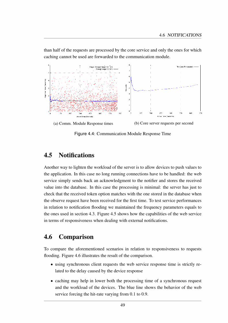
4.6 NOTIFICATIONS
than half of the requests are processed by the core service and only the ones for whichcaching cannot be used are forwarded to the communication module.
(a) Comm. Module Response times (b) Core server requests per second
Figure 4.4: Communication Module Response Time
4.5 Notifications
Another way to lighten the workload of the server is to allow devices to push values tothe application. In this case no long running connections have to be handled: the webservice simply sends back an acknowledgment to the notifier and stores the receivedvalue into the database. In this case the processing is minimal: the server has just tocheck that the received token option matches with the one stored in the database whenthe observe request have been received for the first time. To test service performancesin relation to notification flooding we maintained the frequency parameters equals tothe ones used in section 4.3. Figure 4.5 shows how the capabilities of the web servicein terms of responsiveness when dealing with external notifications.
4.6 Comparison
To compare the aforementioned scenarios in relation to responsiveness to requestsflooding. Figure 4.6 illustrates the result of the comparison.
• using synchronous client requests the web service response time is strictly re-lated to the delay caused by the device response
• caching may help in lower both the processing time of a synchronous requestand the workload of the devices. The blue line shows the behavior of the webservice forcing the hit-rate varying from 0.1 to 0.9.
49
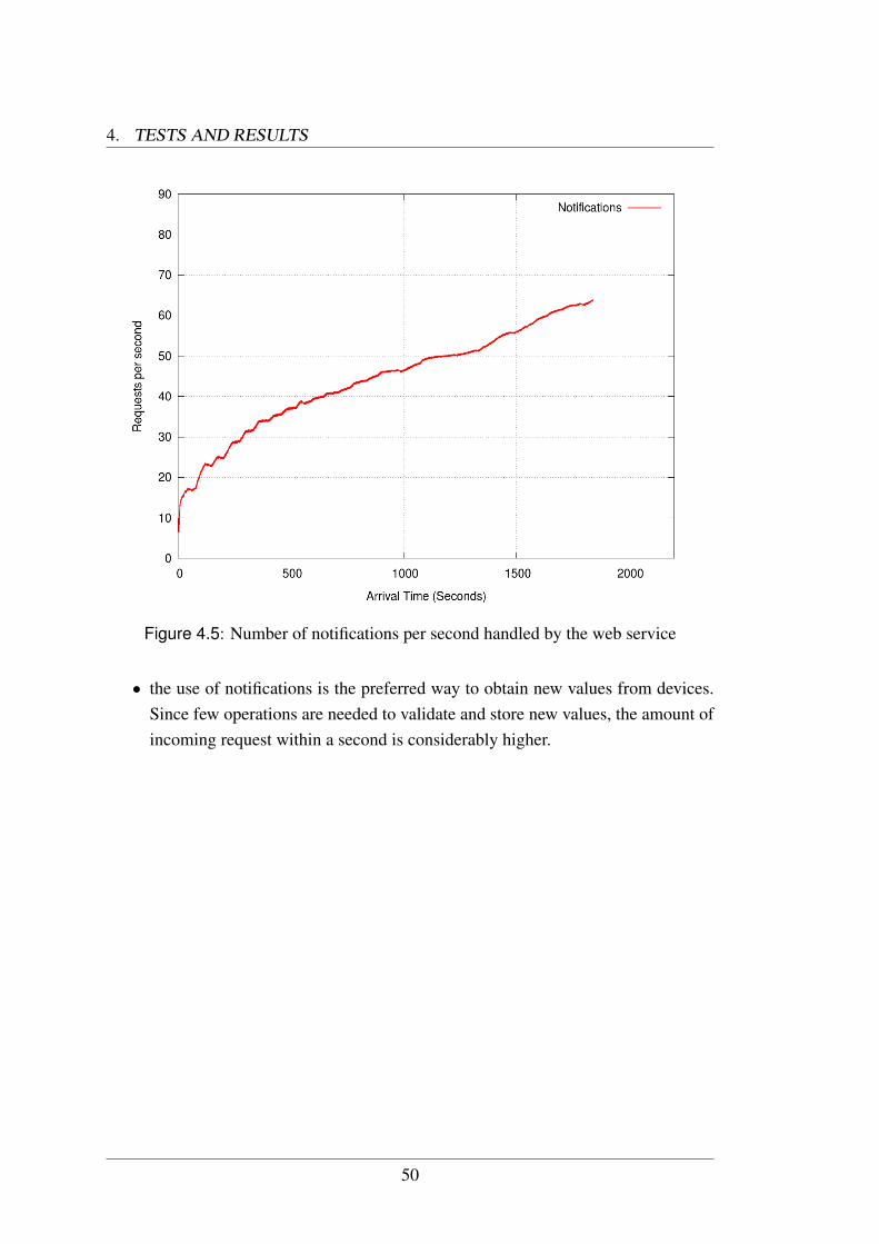
4. TESTS AND RESULTS
Figure 4.5: Number of notifications per second handled by the web service
• the use of notifications is the preferred way to obtain new values from devices.Since few operations are needed to validate and store new values, the amount ofincoming request within a second is considerably higher.
50

4.6 COMPARISON
Figure 4.6: Comparison the responsiveness of the web service using different proce-dures to obtain values
51

4. TESTS AND RESULTS
52

Conclusions and future work
The goal of this thesis was the design and the implementation of a scalable web ser-vice architecture allowing developers to build any kind of application for end users tomanage CoAP devices transparently. The research has mainly focused on exploitingseveral features provided by the protocol. Firstly, we managed to maintain the RESTnature of the protocol in order to reflect this behavior also accessing to resources usinghigher level interfaces proper of the Web. Secondly, exploiting CoAP caching indica-tion allows to lower the workload of the physical network, acting as intermediate ableto understand if a direct interaction with the network is really needed. Thirdly, the webservice is able to act as a CoAP client, making also use of observe features in order toreceive values from the external.
The need of a possible future deployment in cloud computing environments leadsus to consider the possibility of evaluate the dynamic replication of components as wellas their need act concurrently. We point out the implementation details that allow us tostate how the components are ready to accomplish this task.
The web service implements the REST paradigm. The key point of this approachin terms of replication the stateless nature of HTTP protocol. Every pair of requestand response is decoupled from past and future request, and the task to maintain theauthentication or the session is up to the clients. This means that as long as the clientneeds to interact with the web application it is not strictly linked to one particular in-stance or machine, but can interact transparently with a replicated environment hiddenbehind, for example, a load balancer.
The possibility to deploy the core RESTful server from the communication modulepresents several advantages. The simultaneous management of connections with alarge amount of devices can be difficult to handle. In this case multiple machineshandling communication could help to manage efficiently the communication, whileat the same time on the API side there could be no need of replication.
Accesses to database makes use of transactions. Hibernate and Spring provide thenecessary tools in order to identify and mark operations and methods in relation to the
53
CONCLUSIONS
lock they need for accomplishing their tasks.The dynamic scheduling of tasks between multiple nodes is managed transpar-
ently by quartz library. Load balancing occurs automatically. Multiple instances ofthe servers sharing the access to a database will act in such a way that no tasks areperformed twice. Each node tries to fire a job as quick as it can, and the first nodeaccessing the stored information will be the only one that will fire it. Moreover, if oneof the instances fails in accomplish its task, the other nodes in the database will be ableto detect this malfunction and recover the execution of the interrupted tasks. In addi-tion, a newly instantiated node in the network will be able to access to all the alreadyschedule tasks and contribute in fire them concurrently with the previously deployedinstances.
However there are still some issues to face before reaching the full potential ofthis application. Even if CoAP is designed for constrained devices, managing largeamounts of CoAP connections tends to be cost-demanding. In particular, every pend-ing request must be handled in such a way that retransmissions are not delayed dueto computational delays in processing the queued messages. The implementation ofjCoAP we took as reference presents several drawbacks in regards to memory man-agement. For these reasons, in the future it will be necessary to consider differentCoAP implementation or adapt the one we used having strong multithreaded behaviorable to manage properly concurrent connections and queues. After these enhancementswill be achieved, the deployment of a fully working application will be immediate.
54

Bibliography
[1] Zach Shelby and Carsten Bormann. 6LoWPAN: The wireless embedded Internet,volume 43. Wiley, 2011.
[2] Tim Winter. Rpl: Ipv6 routing protocol for low-power and lossy networks. 2012.
[3] Z. Shelby, K. Hartke, C. Bormann, and B. Frank. Constrained Application Pro-tocol (CoAP). IETF Internet Draft draft-ietf-core-coap-13, 2012.
[4] Z. Shelby. Core link format. IETF Internet Draft draft-ietf-core-link-format-14,2012.
[5] A. Castellani, S. Loreto, A. Rahman, T. Fossati, and E. Dijk. Best practicesfor HTTP-CoAP mapping implementation. IETF Internet Draft draft-castellani-core-http-mapping-07, 2013.
[6] Mohammad Mehedi Hassan, Biao Song, and Eui-Nam Huh. A framework ofsensor-cloud integration opportunities and challenges. In Proceedings of the 3rdinternational conference on Ubiquitous information management and communi-cation, pages 618–626. ACM, 2009.
[7] K. Lee, D. Murray, D. Hughes, and W. Joosen. Extending sensor networks intothe cloud using amazon web services. In Networked Embedded Systems for En-terprise Applications (NESEA), 2010 IEEE International Conference on, pages1–7, 2010.
[8] Wei Wang, K. Lee, and D. Murray. Integrating sensors with the cloud using dy-namic proxies. In Personal Indoor and Mobile Radio Communications (PIMRC),2012 IEEE 23rd International Symposium on, pages 1466–1471, 2012.
[9] Sarfraz Alam, Mohammad MR Chowdhury, and Josef Noll. Senaas: An event-driven sensor virtualization approach for internet of things cloud. In NetworkedEmbedded Systems for Enterprise Applications (NESEA), 2010 IEEE Interna-tional Conference on, pages 1–6. IEEE, 2010.
55

BIBLIOGRAPHY
[10] Cosm - connect your world. https://cosm.com/. Accessed: 01/04/2013.
[11] Nibits - the open source internet of things on a distributed cloud. http://www.nimbits.com/. Accessed: 01/04/2013.
[12] Open.sen.se - feel. act. make sense. http://open.sen.se/. Accessed:01/04/2013.
[13] Paraimpu. http://paraimpu.crs4.it/. Accessed: 01/04/2013.
[14] Angelo P Castellani, Salvatore Loreto, Nicola Bui, and Michele Zorzi. Quicklyinteroperable internet of things using simple transparent gateways. In positionpaper in ’Interconnecting Smart Objects with the Internet’ Workshop, March 25,2011.
[15] W. Colitti, K. Steenhaut, N. De Caro, B. Buta, and V. Dobrota. Rest enabledwireless sensor networks for seamless integration with web applications. In Mo-bile Adhoc and Sensor Systems (MASS), 2011 IEEE 8th International Conferenceon, pages 867–872, 2011.
[16] Tim Oareilly. What is web 2.0, 2005.
[17] Luigi Atzori, Antonio Iera, and Giacomo Morabito. The internet of things: Asurvey. Computer Networks, 54(15):2787–2805, 2010.
[18] Michele Zorzi, Alexander Gluhak, Sebastian Lange, and Alessandro Bassi. Fromtoday’s intranet of things to a future internet of things: a wireless-and mobility-related view. Wireless Communications, IEEE, 17(6):44–51, 2010.
[19] Mark Nottingham. Web linking. 2010.
[20] K. Hartke. Observing resources in coap. IETF Internet Draft draft-ietf-core-observe-07, 2012.
[21] Dominique Guinard, Vlad Trifa, and Erik Wilde. A resource oriented architecturefor the web of things. In Internet of Things (IOT), 2010, pages 1–8. IEEE, 2010.
[22] Michael Blackstock and Rodger Lea. Wotkit: A lightweight toolkit for the webof things. 2012.
[23] Alberto Boccato. Un’architettura di database per la virtualizzazione di dispositiviembedded tramite web service. Universita degli Studi di Padova, Dipartimentodi Ingegneria dell’informazione, 2013.
56

[24] Christian Lerche, Klaus Hartke, and Matthias Kovatsch. Industry adoption of theinternet of things: A constrained application protocol survey. In Proceedings ofthe 7th International Workshop on Service Oriented Architectures in ConvergingNetworked Environments (SOCNE 2012), Krakow, Poland, September 2012.
[25] Berta Carballido Villaverde, Dirk Pesch, Rodolfo De Paz Alberola, Szymon Fe-dor, and Menouer Boubekeur. Constrained application protocol for low powerembedded networks: A survey. In Innovative Mobile and Internet Services inUbiquitous Computing (IMIS), 2012 Sixth International Conference on, pages702–707. IEEE, 2012.
[26] Mark Hapner, Rich Burridge, Rahul Sharma, Joseph Fialli, and Kate Stout. Javamessage service. Sun Microsystems Inc., Santa Clara, CA, 2002.
[27] Steve Vinoski. Advanced message queuing protocol. Internet Computing, IEEE,10(6):87–89, 2006.
57

BIBLIOGRAPHY
58