Managing Architectural Decision Models with Dependency...
36
1 Managing Architectural Decision Models with Dependency Relations, Integrity Constraints, and Production Rules Olaf Zimmermann 1 , Jana Koehler 1 , Frank Leymann 2 , Ronny Polley 1 , Nelly Schuster 1 1 IBM Research GmbH Zurich Research Laboratory, Säumerstrasse 4, 8803 Rüschlikon, Switzerland {olz,koe,rpo,nes}@zurich.ibm.com T2 Universität Stuttgart, Institute of Architecture of Application Systems Universitätsstraße 38, 70569 Stuttgart, Germany [email protected] Abstract. Software architects consider capturing and sharing architectural decisions increasingly important; many tacit dependencies exist in this architectural knowledge. Architectural decision modeling makes these dependencies explicit and serves as a foundation for knowledge management tools. In practice, however, text templates and informal rich pictures rather than models are used to capture the knowledge; a formal definition of model entities and their relations is missing in the current state of the art. In this paper, we propose such a formal definition of architectural decision models as directed acyclic graphs with several types of nodes and edges. In our models, architectural decision topic groups, issues, alternatives, and outcomes form trees of nodes connected by edges expressing containment and refinement, decomposition, and triggers dependencies, as well as logical relations such as (in)compatibility of alternatives. The formalization can be used to verify integrity constraints and to organize the decision making process; production rules and dependency patterns can be defined. A reusable architectural decision model supporting service-oriented architecture design demonstrates how we use these concepts. We also present tool support and give a quantitative evaluation. Keywords: Architectural decision, architectural knowledge, decision dependencies, decision tree, dependency pattern, enterprise application, integration, knowledge management, model, SOA, Web services, UML 1 Introduction Having been neglected both in academia and industry for a long time, the importance of architectural decision capturing and sharing is now widely acknowledged [4][12][21]. However, existing work focuses on capturing and visualizing decisions that have been made already. In practice, text templates and informal rich pictures are used to capture this knowledge. Little emphasis is spent on specifying the
Transcript of Managing Architectural Decision Models with Dependency...

1
Managing Architectural Decision Models with Dependency Relations, Integrity Constraints, and
Production Rules
Olaf Zimmermann1, Jana Koehler1, Frank Leymann2, Ronny Polley1, Nelly Schuster1
1 IBM Research GmbH
Zurich Research Laboratory, Säumerstrasse 4, 8803 Rüschlikon, Switzerland {olz,koe,rpo,nes}@zurich.ibm.com
T2 Universität Stuttgart, Institute of Architecture of Application Systems Universitätsstraße 38, 70569 Stuttgart, Germany
Abstract. Software architects consider capturing and sharing architectural decisions increasingly important; many tacit dependencies exist in this architectural knowledge. Architectural decision modeling makes these dependencies explicit and serves as a foundation for knowledge management tools. In practice, however, text templates and informal rich pictures rather than models are used to capture the knowledge; a formal definition of model entities and their relations is missing in the current state of the art. In this paper, we propose such a formal definition of architectural decision models as directed acyclic graphs with several types of nodes and edges. In our models, architectural decision topic groups, issues, alternatives, and outcomes form trees of nodes connected by edges expressing containment and refinement, decomposition, and triggers dependencies, as well as logical relations such as (in)compatibility of alternatives. The formalization can be used to verify integrity constraints and to organize the decision making process; production rules and dependency patterns can be defined. A reusable architectural decision model supporting service-oriented architecture design demonstrates how we use these concepts. We also present tool support and give a quantitative evaluation.
Keywords: Architectural decision, architectural knowledge, decision dependencies, decision tree, dependency pattern, enterprise application, integration, knowledge management, model, SOA, Web services, UML
1 Introduction
Having been neglected both in academia and industry for a long time, the importance of architectural decision capturing and sharing is now widely acknowledged [4] [12] [21]. However, existing work focuses on capturing and visualizing decisions that have been made already. In practice, text templates and informal rich pictures are used to capture this knowledge. Little emphasis is spent on specifying the

2
dependencies between decisions and on sharing information about architectural decisions required and alternatives available. Lack of decision capturing rigor is a possible source of quality problems with the software architectures under construction; insufficient incentives, methods, and tools for decision sharing inhibit active reuse of knowledge and exchange between practitioners on different projects.
Existing decision capturing and sharing models and tools lack a formalization of decisions and their dependencies. Extending our existing Unified Modeling Language (UML) domain metamodel [26], we apply set and graph theory concepts in this paper: We formally define architectural decision issues, alternatives, and outcomes and several types of containment and dependency relations such as decomposition, refinement, triggers, forces, and (in)compatibility. We use these logical and temporal relations to structure the decision models and to organize the decision making.
Such formalization of the data structures in an architectural decision model is useful for several other purposes. It allows knowledge engineers to measure the quality of a reusable decision model developed in a practitioner community. Software architects can evaluate the models they create on individual projects; a decision order makes it possible to navigate through models and to compare them. Graph traversal algorithms can be developed, e.g., calculating path lengths in support of model maintenance. Dependency patterns can also be defined, which helps to detect the incompleteness or inconsistency of a decision model. Finally, knowledge engineers working in other decision capturing domains, e.g., not SOA, or not even software architecture, can reuse the model structure to organize their knowledge.
The remainder of this paper is structured in the following way. Section 2 discusses related work and examples from Service-Oriented Architecture (SOA) design. Section 3 introduces our UML domain metamodel and types of decisions we observed to recur in enterprise application development and SOA design. Section 4 presents the formalization of architectural decision models. Section 5 introduces decision dependency patterns. Section 6 discusses how we implemented and validated our concepts. Section 7 concludes with a summary and an outlook to future work.
2 Related Work
Bass et al. mention the term architectural decision, but not fully define it in “Software Architecture in Practice” [3]. Kruchten et al. [12] define an ontology that describes the attributes that should be captured for a decision, the types of decisions (e.g., executive, existence, and property decisions), when and how decisions are made (i.e., their lifecycle), and several types of decision dependencies. They also focus on the visualization of the decisions and identify many use cases for decision knowledge. Their ontology is semantically rich and defines the knowledge domain both broadly and deeply. However, it is described informally only (i.e., in text). Moreover, design problem and solution are treated as one entity (i.e., alternatives are a dependency type, not an entity). Hence, decisions required (which we refer to as issues) and decisions made (which we refer to as outcomes) can not be separated easily, which limits the reusability of the modeled knowledge. Finally, there are no concepts for structuring decision models apart from the decision types mentioned above.

3
Jansen and Bosch [5] view software architecture as a composition of a set of design decisions. They make the case for decisions to be a first class architecture design concept. Their model for architectural design decisions focuses on change over time as a dominating force driving the decision making. In their metamodel, they distinguish design problems and solutions to them, and outline the attributes that are required to capture related knowledge. Design fragments make it possible to integrate decision models with models for other viewpoints (e.g., logical components and connectors). The metamodel is introduced in text and figures; dependencies between different problems or different solutions remain implicit (i.e., decisions depend on each other if they deal with the same or with related design fragments). There is no overarching model structuring scheme. The reuse of architectural decision knowledge is only touched upon: Design patterns are mentioned as a source of reusable solutions.
Several decision capturing templates exist in industry and academia, which can also be viewed as informally specified metamodels. For instance, the IBM Unified Method Framework (UMF) defines such template in its “architectural decisions” artifact. Architects’ Workbench (AWB) [1] provides modeling tool support for this and many other UMF artifacts: The “Group ADs by Topic” viewpoint in AWB introduces a topic hierarchy and defines an outcome attribute in the decision entity; alternatives are modeled as a separate entity. UMF was formerly known as IBM Global Services Method and has been in use on professional services engagements for IBM clients since 1998. One of the IBM reference architectures comes with a filled out architectural decisions artifact, which contains architectural decisions made during Web application design. Having worked with this artifact, Tyree and Akerman [21] defined another rich decision capturing template, structured into 13 sections. Later on, they proposed an entire ontology to support the design of software architectures [2].
SEURAT, PAKME, ADDSS, The Knowledge Architect, AREL, and Archium are additional tools providing decision modeling capabilities and supporting metamodels. Subsets of these tools are compared in [4] and [5].
In the patterns community, several schools of thought and many pattern templates exist, which can also be used to capture architectural decisions [8]. Requirements in areas such as performance and extensibility typically are referenced in textual intent or forces sections. Many pattern languages remain on an abstract, conceptual level; others specialize on a single problem or technology domain such as enterprise appli-cation architecture [6] or process-driven SOA [23]. Patterns for process-driven SOA describe how to automate the management of long-running business processes such as loan approval processing or order management along supply chains (problem domain) with workflow engines and integration middleware (technology domain). The activity flow in such processes can be specified using Business Process Modeling (BPM) tools and implemented as a network of communicating Web service consumers and providers [24]. In our earlier work, we demonstrated that the relationship between patterns languages and architectural decision models is synergetic: We position architectural patterns as conceptual architecture alternatives in our reusable architectural decision models [26] [28], which capture decisions required and possible solutions. The pattern texts serve as source of architectural decision knowledge.
Defining templates or metamodels and referencing patterns is a good starting point towards more systematic and rigorous decision capturing; however, it does not
4
remove real-world inhibitors for sustainable and maintainable decision sharing such as no immediate benefits, budget and scheduling problems, and lack of tools. Tang et al. report these and several more inhibitors in [20]. To address these issues, we formalize the concepts in existing metamodels and templates and extend them with support for reuse and collaboration: If a comprehensive architectural decision model is created for a certain domain, which can be tailored for particular project at project initiation time, the benefits reported in the literature can be realized by a community of architects over a longer period of time. The budget and tools issues are then faced by an organizational unit (e.g., architecture management group in an enterprise or a community of practice in a professional services firm) rather than by individuals or by project teams. Hence, there are better chances for overcoming them. For instance, a knowledge engineer can be tasked with the creation of a reusable architectural decision model, which is then used by architects on multiple projects.
In the next section, we introduce such reusable architectural decision model and an underlying metamodel. In Section 6, this decision model is presented in more detail.
3 A Domain Metamodel for Capturing Architectural Decisions
A domain metamodel for architectural decision capturing must be expressive enough to support the use cases from [12]. In our reuse and collaboration context, additional use cases are education, knowledge exchange, design method support, review technique, and governance instrument. The metamodel should only define a small set of mandatory attributes so that practitioners are not overwhelmed with information when populating and studying decision models. The metamodel must be machine readable and translatable into other specifications, e.g., into Web services contracts and relational database schemas, so that tool support for decision modeling and dependency management can be built.
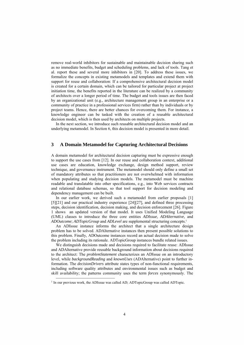
In our earlier work, we derived such a metamodel from earlier proposals [1] [5] [21] and our practical industry experience [24] [27], and defined three processing steps, decision identification, decision making, and decision enforcement [26]. Figure 1 shows an updated version of that model. It uses Unified Modeling Language (UML) classes to introduce the three core entities ADIssue, ADAlternative, and ADOutcome; ADTopicGroup and ADLevel are supplemental structuring concepts.1
An ADIssue instance informs the architect that a single architecture design problem has to be solved. ADAlternative instances then present possible solutions to this problem. Finally, ADOutcome instances record an actual decision made to solve the problem including its rationale. ADTopicGroup instances bundle related issues.
We distinguish decisions made and decisions required to facilitate reuse: ADIssue and ADAlternative provide reusable background information about decisions required to the architect: The problemStatement characterizes an ADIssue on an introductory level, while backgroundReading and knownUses (ADAlternative) point to further in-formation. The decisionDrivers attribute states types of non-functional requirements, including software quality attributes and environmental issues such as budget and skill availability; the patterns community uses the term forces synonymously. The
1 In our previous work, the ADIssue was called AD; ADTopicGroup was called ADTopic.

5
role and phase attribute serve as link to general-purpose methodologies such as the Rational Unified Process (RUP) [11].
Fig. 1. UML metamodel for architectural decision capturing and reuse.
ADOutcome instances capture project-specific knowledge about decisions made. The justification information refers to actual requirements (“sub-second response time in customer interface”), as opposed to the ADIssue-level decision drivers which only list types of requirements (“performance, i.e., response time and throughput”). These two knowledge aspects have different reuse characteristics: Naturally, the ADIssue and ADAlternative information about decisions required and available solutions has more reuse potential then the project-specific rationale. A second reason for factoring out ADOutcome as a separate entity is that the same ADIssue might pertain to many elements in a design model, e.g., business processes and Web service operations in SOA. Therefore, types of design model elements are referenced via the scope attribute in the ADIssue. ADOutcome instances then can be created dynamically on projects, and can refer to design model element instances via their name.
To give an example, a business process model for order management might state that three “customer enquiry”, “claim check”, and “risk assessment” business processes have to be implemented in an insurance industry case.2 One ADIssue is to select an INTEGRATION TECHNOLOGY3 to let the activities in each of the three business processes interact with other systems, with ADAlternatives such as WEB SERVICES and RESTFUL INTEGRATION [15]. Problem statement (“Which technology should be used to let the activities in a business process communicate with Web services and legacy systems?”) and decision drivers (“interoperability”, “reliability”, and “tool support”) are the same for all three business processes. Hence, it is sufficient to create
2 See [24] for an order management SOA case study from the telecommunications industry. 3 In all further examples, we set ADIssues and ADAlternatives in THIS FONT (small caps).

6
a single ADIssue instance which has a “business process” scope. This value of the scope attribute refers to a type of SOA-specific design model element.
Decision outcome information such as the chosen alternative and its justification depends on the individual requirements of each process, e.g., “for customer enquiry, we decide for WEB SERVICES as a Java and a C# components have to be integrated in an interoperable manner and Web services tool support exists for these languages” and “for risk assessment, we select RESTFUL INTEGRATION because not all of the involved backend systems support XML and SOAP processing”. Hence, three ADOutcome instances are created and associated with the same ADIssue. These instances capture the process-specific decision and its rationale. They refer to the actual business processes in their name attributes (“customer enquiry”, “claim check”, and “risk assessment”).
Closely related ADIssues are grouped into ADTopicGroups, which form a hierarchy. This hierarchy serves as a table of content: Each ADTopicGroup hierarchy is assigned to one of several ADLevels of refinement, e.g., conceptual level, technolo-gy level, or vendor asset level. The resulting structure makes issues easy to locate.
Decision dependencies are explicitly modeled as UML associations between ADIssues. We defined a single dependsOn association in Figure 1; in Section 4, we introduce additional dependency types that correspond to those defined in [12].
Rationale. Our metamodel extends that from [1] and [5], e.g., with the levels concept. Jansen and Bosch also separate problem (issue) from solution (alternative), and define how to scope decisions via design fragments. Similar entities and concepts for method alignment can be found in the core model defined by de Boer et al. [4], which was developed independently of and simultaneously to our UML model. Unlike de Boer et al., we also define attributes, which is required to support reuse and collaboration. In particular, we define attributes that are required for lifecycle management of ADIssues in the reusable part (e.g., role) and ADOutcomes in project-specific decision models (e.g., changedBy).
The level structure is motivated by our observation that when designing enterprise applications, the technical discussions often circle around detailed features of certain vendor products, or the pros and cons of specific technologies, whereas many highly important strategic decisions and general concerns are underemphasized. These discussions are related, but should not be merged into one; they reside on different refinement levels. Separating design concerns in such a way is good practice; Fowler [6] and RUP with its elaboration points recommend a similar incremental approach for UML class diagrams used as design models. We adopted this recommendation for decision models. It is possible to select other ADTopicGroup hierarchies. For instance, panes in enterprise architecture frameworks and logical viewpoints can also be used as structuring mechanisms.
Example. A Reusable Architectural Decision Model (RADM) for SOA serves as a running example throughout this paper. It was created in an industrial decision har-vesting project that started in January 2006 (see Section 6 for more information). All 389 decisions captured so far conform to the metamodel shown in Figure 1.
Table 1 shows several ADIssue examples from the RADM for SOA and assigns them to seven decision types. We found many instances of these seven decision types during the creation of the RADM for SOA (see Section 6 and [26] for rationale):

7
Table 1. Decision types and SOA examples (RADM for SOA)
Decision type ADLevel ADTopicGroups and ADISSUES (in SMALL CAPS) Executive decisions, requirements analysis decisions
Executive level Out of scope of this paper, introduced in [26] and elaborated upon in [28].
Pattern Selection Decisions (PSDs)
Conceptual level
ADTopicGroup “Service Layer Realization Decisions”: IN MESSAGE GRANULARITY MESSAGE EXCHANGE PATTERN INVOCATION TRANSACTIONALITY PATTERN
ADTopicGroup “Process Layer Realization Decisions”: SERVICE COMPOSITION PARADIGM
ADTopicGroup “Integration Layer Realization Decisions”: INTEGRATION STYLE BROKER, ADAPTER, REGISTRY PATTERN USAGE
Pattern Adoption Decisions (PADs)
Conceptual level
Process Layer Realization Decisions: MACROFLOW MICROFLOW PROCESS ACTIVITY TRANSACTIONALITY (PAT)
Integration Layer Realization Decisions: COMMUNICATIONS TRANSACTIONALITY (CT) REGISTRY LOOKUP TIME
Technology Selection Decisions (TSDs)
Technology level ADTopicGroup “Service Layer Technology Decisions”: TRANSPORT PROTOCOL CHOICE MESSAGE EXCHANGE FORMAT
ADTopicGroup “Process Layer Technology Decisions”: SERVICE COMPOSITION LANGUAGE
ADTopicGroup “Integration Layer Technology Decisions”: INTEGRATION TECHNOLOGY AUTHORIZATION TECHNOLOGY
Technology Profiling Decisions (TPDs)
Technology level
Service Layer Technology Decisions: SOAP COMMUNICATION STYLE WEB SERVICES TRANSACTIONALITY
Process Layer Technology Decisions: BPEL VERSION COMPENSATION TECHNOLOGY
Integration Layer Technology Decisions: TRANSPORT QOS XML SCHEMA CONSTRUCTS
Vendor Asset Selection Decisions (ASDs)
Vendor asset level
ADTopicGroup “Service Layer Asset Decisions”: SOAP ENGINE
ADTopicGroup “Process Layer Asset Decisions”: BPEL ENGINE SCA IMPLEMENTATION
ADTopicGroup “Integration Layer Asset Decisions”: ESB GATEWAY
Vendor Asset Configuration Decisions (ACDs)
Vendor asset level
Service Layer Asset Decisions: IBM SOAP ENGINE DEPLOYMENT MODE AXIS2 SOAP ENGINE DEPLOYMENT MODE
Process Layer Asset Decisions: (WPS BPEL) INVOKE ACTIVITY TRANSACTIONALITY SCA QUALIFIERS
Integration Layer Asset Decisions: ESB TOPOLOGY

8
In addition to the three levels already introduced, we use an executive level in the RADM for SOA, which comprises executive decisions as defined in the taxonomy from Kruchten et al. [12].
Pattern Selection Decisions (PSDs) are concerned with choosing certain architectural patterns from the vast body of patterns available in the literature. Pattern Adoption Decisions (PADs) also deal with architecture and design patterns, but in a more detailed way, e.g., selecting certain pattern variants and pattern primitives once a PSD has been made. Such PADs often can be found in the pattern texts, e.g., in bulleted lists, cheat sheets and overview diagrams in patterns books. Pattern language primitives and grammars as defined by Zdun et al. [23] are another source of PADs.
Technology Selection Decisions (TSDs) select certain technologies that implement the selected and adopted patterns; Technology Profiling Decisions (TPDs) follow them, specifying implementation details such as subsets of technology standards to be employed. An example TPD is the decision about the XML SCHEMA CONSTRUCTS that are selected from the many options in the XML schema standard to serve as request and response message parameters defined for service operations.
Asset Selection Decisions (ASDs) pick commercial products or open source assets supporting the selected and profiled technologies; Asset Configuration Decisions (ACDs) then cover installation and customization details of these products.
Let us give another, more advanced example. When implementing the three business processes for order management introduced above, a conceptual PSD for a SERVICE COMPOSITION PARADIGM is required, deciding whether the processes should be made executable in a workflow engine, or be realized in traditional programming language code. If a workflow engine is decided for, a related TSD is to agree on a SERVICE COMPOSITION LANGUAGE such as Business Process Execution Language (BPEL). Another related issue is to select a BPEL ENGINE as an ASD, e.g., Active BPEL, IBM WebSphere Process Server or Oracle BPEL Process Manager. For each of the activities in a business process and for each invoked Web service, the INVOCATION TRANSACTIONALITY PATTERN and INTEGRATION STYLE have to be decided. These issues have several related PADs, TPDs, and ACDs. This fairly complex set of issues will serve as our example later in this paper.
While the content in this particular RADM is specific to enterprise application development and SOA, the concepts presented in the next section provide generic solutions to the decision capturing and sharing problems outlined in Sections 1 and 2.
4 A Formal Model for Decision Modeling with Reuse
Existing decision capturing approaches are based on text templates or informally specified metamodels. Their main usage scenario, architecture documentation, has a retrospective nature (even if the captured knowledge is shared later). In such a setting, each decision is captured from scratch and ad hoc as it is made during design. In some approaches, it is mined from other artifacts. On the contrary, our approach emphasizes the proactive sharing of reusable background information about recurring design issues, captured in ADIssue and ADAlternative instances. Such reusable decision model can steer software architects through the decision making, informing them

9
about decisions required and highlighting the problems to be solved. For recurring ADIssues, only the ADOutcome instances have to be created on the project.
To be able to use a reusable decision model in such active guiding role, additional concepts are required. For instance, a structure must be defined that organizes large models and makes them consumable; a decision making order must be specified. To do so, we complement the UML model from Section 3 with formal definitions now. The rationale behind and motivating examples for each concept come from the SOA domain; however, it is an explicit design goal for our modeling concepts that the concepts can also be applied to other architectural domains.
4.1 Elementary Definitions for Architectural Decision Modeling
Basic concepts from set and graph theory are adequate to define the entities in the UML model and the relations between them. We begin with representations for the UML classes ADTopicGroup, ADIssue, and ADAlternative from Figure 1.
Definition 1 (Architectural Decision Topic Groups T) Let T be a set of architectural decision topic groups T = {(n, s, d) x n, s, d c Strings} where the tuple (n, s, d) represents the name, short name, and description of an architectural decision topic group.4
Rationale and example: An architectural decision topic group (short: topic group) represents closely related design concerns. For instance, in the RADM for SOA, one topic group per architectural layer is defined on each refinement level (Table 1 in Section 3). An example is the ADTopicGroup “Service Layer Realization Decisions”.
It is worth noting that our topic groups are different from the topics in [4]. They do not represent individual design issues, but group such issues. Representing individual design issues is the purpose of the next entity: Definition 2 (Architectural Decision Issues I) Let I be a set of architectural decision issues I = {(n,s,p,r, {tt}) x n, s, p, r, tt c Strings} where n is a name, s a scope, p a project phase, r a role attribute, and {tt} a set of topic tag strings.
Rationale and example: An architectural decision issue (short: issue) represents a single design concern. Name, scope, phase, role are describing texts. The name is used to identify and list issues. The topic tags index the model content. They can be used to locate issues by subject area keyword. In the RADM for SOA outlined in Section 3, we use the names of the decision types from Table 1 as topic tags, as well as important non-functional concerns such as security and transaction management. Hence, the architect can query the model for all PSDs (as introduced in Section 3), all issues dealing with security and/or transaction management, etc.
In our SOA decision model, two PSDs deal with the MESSAGE EXCHANGE PATTERN (dealing with the abstract protocol syntax and synchrony of service invocations) [9] and the INVOCATION TRANSACTIONALITY PATTERN (dealing with system transactions as an approach to protecting shared resources from invalid
4 The other attributes from the UML model are irrelevant for the formalization.

10
concurrent access, e.g., lost updates and phantom reads [6]). Another issue is the IN MESSAGE GRANULARITY PSD, which concerns the syntax (breadth and depth) of the in message parameters. These issues are listed in Table 1 in Section 3.
An architectural decision issue captures a single design concern or problem without modeling possible solutions to it. Architectural decision alternatives do so:
Definition 3 (Architectural Decision Alternatives A) Let A be a set of architectural decision alternatives A = {(n, d) x n, d c Strings} where n is a name and d is a solution description.
Rationale and example: An architectural decision alternative (short: alternative) presents a single solution to the design problem expressed by an ADIssue. For instance, the MESSAGE EXCHANGE PATTERN can decide between synchronous REQUEST REPLY and asynchronous ONE WAY message exchange. Two alternatives for the INVOCATION TRANSACTIONALITY PATTERN might be TRANSACTION ISLANDS (do not let service consumer and provider share a single transaction context) and TRANSACTION BRIDGE (propagate transaction context with a service invocation) [24].
Definition 4 (contains relations \T, \I, \A, \) Let \T ` T × T be a contains relation defined between topic groups, \I ` T × I be a contains relation defined between topic groups and issues, and \A ` I × A be a contains relation defined between issues and alternatives. Subsequently, we only speak of the contains relation \ = \T 4 \I 4 \A. If (a \ b), we also say that a contains b and b is contained in a.
Rationale and example: The contains relation \ allows us to define a single hierarchical structure, which serves as a table of content, allowing the architect to locate issues and alternatives easily in the reusable architectural knowledge and helping the knowledge engineer to avoid undesired redundancies. One or more alternatives solve a particular issue. Related issues can be put into one topic group. Related topic groups can be placed in the same parent topic group. Figure 2 illustrates the tree structure resulting from the \ relation:
t2t2
i1i1
a1a1
a2a2
t1
t3t3
i3i3 a6a6i2i2
a3a3
a5a5
t4t4
a4a4
topicgroup
issueissue
alt.alt.
Fig. 2. General organization of an architectural decision tree, indices reflect an ordering of the
topic groups, issues and alternatives.
In the UML metamodel in Figure 1, the \ relation is represented by the three associations (arrows with filled with solid diamonds at originating end) that express physical containment between ADTopicGroups, ADIssues and ADAlternatives, respectively.

11
We define only a single tree structure (i.e., no overlays), and one alternative can only be a solution to one design issue. This modeling decision is justified by our emphasis on reuse: In reusable architectural decision models, knowledge engineers describe the attributes of the alternatives relative to the problem statement and the decision drivers of an issue, which makes it necessary to define a 1:n relation (also see UML model in Section 3). If a pattern, technology, or asset solves multiple problems, it is referenced in multiple alternatives. We faced a tradeoff between normalization (i.e., no redundancy) and precision (accuracy) when making this modeling decision; we consider the latter requirement to be more important in our usage context.
Definition 5 (Architectural Decision Tree ) Using T, I, A, and the \ relation, we can define an architectural decision tree = (T 4 I 4 A,\) with a single root node t0 c T called the root topic.5 In , a topic group contains zero or more other topic groups and issues, while an issue contains zero or more alternatives. In this tree, each topic group t c T except the root topic is contained in exactly one other topic group ti c T:
≤ t, ti , tj c T: (ti \ t) . (tj \ t) u ti = tj
Each issue i c I must be contained in exactly one topic group t c T:
≤ i c I: ≥ t c T (t \ i) ≤ i c I, ti , tj c T: (ti \ i) . (tj \ i) u ti = tj
Each alternative a c A must be contained in exactly one issue i c I:
≤ a c A: ≥ i c I (i \ a) ≤ ii, ij c I, a c A: (ii \ a) . (ij \ a) u ii = ij
Rationale and example: Modeling architectural decisions in itself is not new: Ran and Kuusela also propose (but do not formalize) the notation of Design Decision Trees (DDTs) [16]. Our formalization allows us to define advanced concepts later.
The topic group hierarchy may mimic the containment hierarchy of a design model, e.g., beginning with architectural layers. In our RADM for SOA, parts of the hierarchy resemble the containment hierarchy of a Web service definition. “Service” is one of the conceptual patterns that define SOA as architectural style and Web Services Description Language (WSDL) [22] is one of several technology options to express service contracts; WSDL port types define service operations through in messages accepted and out messages returned. Both service pattern and WSDL technology have several issues attached (for examples, see Table 1). Consequently, “Service Layer Realization Decisions” is a topic group on the conceptual level, which has child topic groups such as “Operation Design” and “Message Design” (not shown in Table 1). Such containment relations between design model elements exist in many application genres and architectural styles. Architectural layering is a popular structuring principle [6].
5 In graph theory, a directed graph is a pair G = (V, E) where V is a set of vertices (or nodes)
and E is a subset of V × V relations (ordered pairs) called edges (arcs). A graph that does not contain any cycles is an acyclic graph. A directed acyclic graph is often called a DAG. A tree is a DAG with a single root node and a single path from any node to the root node.

12
Figure 3 instantiates the abstract tree structure from Figure 2 for parts of our SOA example:
t2t2
od1od1
t1
t3t3
imd1imd1od2od2
t4t4
OPERATIONDESIGN (od) MESSAGEDESIGN (md)
MESSAGEEXCHANGEPATTERN
INMESSAGEGRANULARITY
COARSEGRAINED
TXISLANDS
TX BRIDGE
STRAT.STILTS
REQREPLY
ONEWAY
issueissue
alt.alt.
INMESSAGEDESIGN (imd)
INVOCATIONTRANSACTIONALITY
PATTERN
SRD – SERVICELAYERREALIZATIONDECISIONStopicgroup
Fig. 3. An instantiated example tree showing a subset of issues that must be resolved when
adding Web services to an architecture.
Definition 6 (Ordered Tree ) We define an ordering among the child nodes of identical type (topic group, issue, alternative) contained in a node in order to be able to enumerate sibling nodes of the same type sharing the same parent node, i.e., we introduce <T, <I, <A.
Rationale and example: An ordering relation defines a recommended reading sequence, and can be used to express integrity constraints on architectural decision trees (which we will define later). In the simplest case, the <T, <I, and <A relations can be the alphanumeric sorting of the topic group, issue, and alternative names. Note that a topic group may contain other topic groups and issues. In this case, we order all topic group siblings before all issue siblings. This yields an ordered tree ; we refer to its total order relation as <.
4.2 Multi-Level Architectural Decision Model and Logical Relations
The meta model from Section 3 and the elementary definitions from Section 4.1 allow knowledge engineers to capture decisions and organize the knowledge in a topic group hierarchy. However, the resulting ordered architectural decision tree does not yet support the vision of an active, managed decision model taking a guiding role during architecture design. More relations between topic groups, issues, and alternatives must be defined.6 In this section, we introduce logical constraints; followed by temporal dependencies in Section 4.3. Again, we apply concepts from graph theory. Definition 7 (Architectural Decision Model , root topic, initial issue) An architectural decision model is a partially ordered set of architectural decision trees 00,…, 10,…, km arranged in levels L0,…,Lk. Each tree belongs to exactly one
6 Note that the UML model in Section 3 only defined a generic “dependsOn” association.

13
level and each level must contain at least one tree, i.e., no empty levels exist. A tree ki is the i-th tree in level k. If k < l, we speak of tree ki having a higher level than tree
lj and lj having a lower level than ki. Each architectural decision model has exactly one distinguished root topic, which is the root topic of 00 in the highest level L0. Accordingly, the first issue in the distinguished root topic (according to <I) is identified as the initial issue.
We also say that the issues in a tree reside on the level this tree belongs to. Rationale: Architectural decision models define the multi-level structure required for knowledge bases such as that outlined in Table 1 in Section 3. The partial order assigns topics and issues to different levels of abstraction and refinement. Figure 4 illustrates the concepts from Definition 7:
t1t1
i00 2 i00 2
a1a1
a2a2
i00 3i00 3 a1a1
issueissue
alt.alt.L0
L2
L1
t1t1
i01 2i01 2 a1a1
t2t2
T00T01
root topic
Initial issue
t1t1i10 1i10 1
a1a1
a2a2
T10
t1t1i20 1i20 1
a1a1
a2a2
T20
(d)ecomposesInto
(r)efinedBy
d
r
rcontains
i00 1i00 1
a1a1
a2a2
topicgroup
d
Fig. 4. A multi-level architectural decision model with four trees, root topic, and initial issue.
Figure 4 already shows relations not defined yet: i00 1 decomposes into i00 2, and i00
3, which in turn is refined by i10 1 and then i20 1. These relations formally capture how issues residing in different levels and trees of a model can be combined in order to express that an abstract, conceptual design is elaborated upon on the same or on a lower, more concrete level of refinement: Definition 8 (influences, refinedBy, decomposesInto relations) Let be an architecture decision model with levels L0,…,Lk and trees 00 ,…, km associated with levels L0,…,Lk. The following relations are defined between issues i00

14
0,…, ikm n c I where an issue ikm n is the n-th issue in the m-th tree Tkm contained within level Lk of a model .
• influences(ijl n, ikm o) with j, k, l, m, n, o arbitrary. The influences relation captures cross-cutting concerns between issues. It adds additional undirected edges to the model that do not necessarily have to form a connected graph. The relation is symmetric, i.e., if ii influences ij, then ij
influences ii. In addition, the influences relation is not reflexive, but transitive. An issue can influence several other issues and it can also be influenced by several other issues.
• refinedBy(ijl n, ikm o) with j < k and l, m, n, o arbitrary. The refinedBy relation links issues that have to be investigated at several levels. It adds additional directed edges to the model that must always lead from an issue in a higher level to an issue in a lower level of the model, i.e., no cycles can occur. The relation is transitive, but not reflexive, and not symmetric. If k = j + 1, i.e., an issue refines an issue that resides on the subsequent level, we speak of a strict refinedBy relation. Issues in level L0 cannot refine any other issue, while an issue in the lowest level Lk cannot be refined by any issue. If i1 refinedBy i2, i1 is referred to as having an outgoing refinement relation and i2 as having an incoming one.
• decomposesInto(ijl n, ikm o) with j = k and l, m, n, o arbitrary. The decomposesInto relation expresses functional aggregation. It adds additional directed edges between issues within the same level. The relation is transitive, but neither reflexive nor symmetric. No cycles are permitted.
If (i1 influences i2), we also say that i1 influences i2 and that i2 is influenced by i1; if (i1 refinedBy i2), we also say that i1 is refined by i2 and that i2 refines i1; if (i1 decomposesInto i2), we also say that i1 decomposes into i2 and that i2 is a decomposition of i1.
Table 2 summarizes the main properties of the relations.
Table 2. Decision relations between architectural decision issues and their properties
Relation Set(s) Reflexive/ symmetric/ transitive
Cardinality Other properties
influences I × I no/yes/yes n:m (no function)
–
refinedBy I × I no/no/yes 0..1:0..1 (function)
Introduces one or more additional DAGs (i.e., no cycles permitted); only from higher to lower level (next lower if strict).
decomposesInto
I × I no/no/yes 0..1:n (no function)
No cycles permitted. Only within same level.
Rationale and examples: We compare these relations with those defined by Kruchten et al. in Section 6. SOA examples are given later in this section (Figure 5).
The influences relation can be used to express cross-cutting concerns without making any assumptions about the level and order of the related decisions. For instance, the choice of a BPEL ENGINE also has to do with the AUTHORIZATION

15
TECHNOLOGY. However, the relation is not refinedBy because the two issues belong to the same refinement level. The relation is not decomposesInto either because the issues deal with different subject areas (workflow and security). The influences relation is often used in rapid decision capturing efforts and replaced by one of the more elaborate forms such as refinedBy and decomposesInto as the decision model matures during subsequent knowledge engineering iterations.
The refinedBy relation allows us to model that the same issue typically has to be investigated at several stages of a software development process. A level can correspond to a Model-Driven Architecture (MDA) model type such as platform-independent model and platform-specific model, or to a development milestone, e.g., an elaboration point defined in RUP. A conceptual pattern such as SERVICE COMPOSITION PARADIGM abstracts away from any particular technology. Consequently, a SERVICE COMPOSITION LANGUAGE like BPEL has to be selected in refinement of the conceptual decision to adopt the WORKFLOW pattern as the SERVICE COMPOSITION PARADIGM. A particular BPEL ENGINE vendor asset has to be selected if BPEL is the selected SERVICE COMPOSITION LANGUAGE.
The decomposesInto relation expresses functional aggregation of issues. When following the separation of concerns principle, complex design problems are often broken down into to smaller, more manageable units of design work (often referred to as divide-and-conquer approach to problem solving). These units can then be investigated separately (but being aware of the dependency between them).
With these relations introduced, we can define two logical constraints on architectural decision models .
Integrity Constraint 1 The refinedBy and decomposesInto relations are mutually exclusive.
≤ii, ij : ii refinedBy ij u ¬ (ii decomposesInto ij )
and ≤ii, ij : ii decomposesInto ij u ¬ (ii refinedBy ij)
Rationale: This follows from our basic definitions, because the refinedBy relation is defined between issues residing on different levels, while the decomposesInto relation is only defined between issues residing on the same level.
Integrity Constraint 2 If two issues have a refinedBy or a decomposesInto relation they cannot have an influences relation and vice versa.
≤ii, ij : ii refinedBy ij - ii decomposesInto ij u ¬ (ii influences ij) ≤ii, ij : ii influences ij u ¬ (ii refinedBy ij - ii decomposesInto ij)
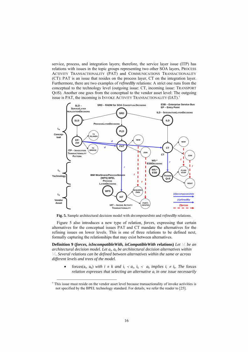
Rationale and example: This constraint avoids unnecessary redundancies in the model. Figure 5 adds the three levels we introduced in Section 3 to our running example, the design of transactional workflows in SOA. The topic group hierarchy is shown: three SOA layers, the service layer, the process layer, and the integration layer, are represented by separate topic groups. The PSD INVOCATION TRANSACTIONALITY PATTERN (ITP) is an example for the decomposition of a complex conceptual decision into two more primitive ones residing on the same level (here: conceptual): The transactionality of a service operation in the SOA decision model is a non-functional design concern. It affects design model elements in the
16
service, process, and integration layers; therefore, the service layer issue (ITP) has relations with issues in the topic groups representing two other SOA layers, PROCESS ACTIVITY TRANSACTIONALITY (PAT) and COMMUNICATIONS TRANSACTIONALITY (CT): PAT is an issue that resides on the process layer, CT on the integration layer. Furthermore, there are two examples of refinedBy relations: A strict one runs from the conceptual to the technology level (outgoing issue: CT, incoming issue: TRANSPORT QOS). Another one goes from the conceptual to the vendor asset level: The outgoing issue is PAT, the incoming is INVOKE ACTIVITY TRANSACTIONALITY (IAT).7
SLD
PAT
SRD
EP:ITP
SRD – RADM for SOA CONCEPTUALDECISIONS
ITP – INVOCATIONTRANSACTIONALITY
PATTERN
TXISLANDS
PLD
ILDPROCESSLAYERDECISIONS
ILD – INTEGRATIONLAYERDECISIONS
CT
JOINCT
NEW
(d)ecomposesInto
(r)efinedBy
WPS
IAT
IAT – INVOKE ACTIVITY TRANSACTIONALITY
REQUIRESOWN
PARTI-CIPATES
WS-*ESB
TRANSP.QOS
PLAINSOAP
WS-*ESBDECISIONS
IBM WEBSPHEREPROCESSSERVER(WPS) BPEL
PROCESSLAYERDECISIONS
d
fr
r
d
TXBRIDGE
JOIN
NEW
f
ESB – Enterprise Service BusEP – Entry Point
L0
Concep-tual
L2
VendorAsset
L1
Technology
SLD –SERVICELAYER
REALIZATIONDECISIONS
WSAT
f
f
(f)orces
Fig. 5. Sample architectural decision model with decomposesInto and refinedBy relations.
Figure 5 also introduces a new type of relation, forces, expressing that certain alternatives for the conceptual issues PAT and CT mandate the alternatives for the refining issues on lower levels. This is one of three relations to be defined next, formally capturing the relationships that may exist between alternatives.
Definition 9 (forces, isIncompatibleWith, isCompatibleWith relations) Let be an architectural decision model. Let ai, ak be architectural decision alternatives within
. Several relations can be defined between alternatives within the same or across different levels and trees of the model.
• forces(ai, ak) with i ! k and ii \ ai, ik \ ak implies ii ! ik. The forces relation expresses that selecting an alternative ai in one issue necessarily
7 This issue must reside on the vendor asset level because transactionality of invoke activities is
not specified by the BPEL technology standard. For details, we refer the reader to [25].

17
means that an alternative ak in another issue has to be selected. It adds additional directed edges between alternatives. The relation is not reflexive and not symmetric, but transitive. It must not form any cycles.
• isIncompatibleWith(ai, ak) with i ! k. The isIncompatibleWith relation expresses that certain combinations of alternatives do not work together. It adds additional undirected edges to . The relation is symmetric, but neither transitive nor reflexive. It must not form any cycles.
• isCompatibleWith(ai, ak) with i, k arbitrary. The isCompatibleWith relation expresses that certain combinations of alternatives work together. The relation defines an equivalence relation, i.e., it is reflexive, symmetric, and transitive and thus identifies classes of compatible alternatives.
If (a1 forces a2), we also say that a1 forces a2 and that a2 is forced by a1; if (a1 isIncompatibleWith a2), we also say that a1 is incompatible with a2 and that a2 is incompatible with a1; if (a1 isCompatibleWith a2), we also say that a1 is compatible with a2 and that a2 is compatible with a1.
Table 3 summarizes the main properties of the relations.
Table 3. Logical relations between architectural decision alternatives and their properties
Relation Set(s) Reflexive/ symmetric/ transitive
Cardinality Other properties
forces A × A
no/no/yes n:m (no function)
Still a DAG, which does not have to be connected.
isIncompatibleWith A × A no/yes/no n:m (no function)
–
isCompatibleWith A × A yes/yes/yes n:m (no function)
Default if no other relation exists between two alternatives.
Our next two integrity constraints pertain to these three relations.
Integrity Constraint 3 A forces relation implies that an alternative in one issue is incompatible with all other alternatives in that issue:
≤ ai, aj, ak, ij \ aj, ij \ ak, j ! k: ai forces aj u ai isIncompatibleWith ak
Integrity Constraint 4 The forces, isIncompatibleWith, and isCompatibleWith relations between alternatives are mutually exclusive; one of them must exist. If nothing is defined, isCompatibleWith is the default.
≤ai, aj : ai forces aj . ai isIncompatibleWith aj ≡ false ≤ai, aj : ai isIncompatibleWith aj . ai isCompatibleWith aj ≡ false
≤ai, aj : ai forces aj . ai isCompatibleWith aj ≡ false ≤ai, aj : ai forces aj - ai isIncompatibleWith aj - ai isCompatibleWith aj ≡ true
Rationale and example: We compare these relations with those defined in the ontology from Kruchten et al. in Section 6.
The isIncompatibleWith relation expresses that certain combinations of alternatives do not work with each other, for instance a NON-TRANSACTIONAL BACKEND service provider (not shown in Figure 5) can not be called from a service consumer that has

18
been decided to share transaction context with its provider (i.e., PAT decision to JOIN in Figure 5). A forces relation specifies that an alternative can only be combined with one alternative in a different issue. For example, a conceptual alternative to share transaction context (PAT decision to JOIN) requires the technology-level Enterprise JavaBean (EJB) transaction attribute to be set to TX_MANDATORY.
In addition to the four formally defined integrity constraints, several heuristics can also be defined for an architectural decision model .
Definition 10 (Balanced Architectural Decision Model) An architectural decision model is balanced if and only if the following informally defined heuristics regarding its structural properties hold:
1. has at least two, but not more than five levels. 2. Topic groups do not contain more than nine other topic groups and twelve
issues. 3. On all but the lowest level, there is at least one issue that has an outgoing
refinedBy relation. 4. On all but the highest level, there is at least one issue that has an
incoming refinedBy relation. 5. The maximum path length to get from the initial issue to any issue via the
contains relation \ and the maximum path length to get from the initial issue to any issue via refinedBy and decomposesInto relations is ten.
Rationale and example: Quality attributes such as usability and consumability for humans (e.g., knowledge engineers, software architects) justify these heuristics: An unbalanced model is difficult to maintain (for the knowledge engineer) and consume (for the software architect) due to the many elements per topic group and lengthy reasoning paths. According to studies in cognitive science and user interface design, three [13] to seven (plus/minus two) [14] entries on each level of a hierarchy are considered consumable. Good practices in object-oriented design give similar advice for inheritance trees [17]. Heuristic 1 adopts this advice; heuristic 2 and 5 are more tolerant due to experience we gained during RADM for SOA creation and tool implementation (see Section 6): Seven to nine architectural layers are defined in many reference architectures, e.g., SOA reference architectures and OSI networking, and we often find around ten components in each layer of a component-oriented architecture. If the topic group hierarchy resembles the architectural layering and logical decomposition into components, it must be able to deal with such numbers of topics groups and issues. Figure 5 shows a balanced architectural decision model.
4.3 Temporal Relations/Constraints and Decision Making Process Support
We add a relation to our model that facilitates the decision making process conducted by the software architect. Unlike previous definitions, this relation is not binary and defined between nodes of different types.
Definition 11 (triggers relation) Let be an architectural decision model. Let ai, aj be architectural decision alternatives in , let ik be an issue in , and let tl be a topic group in .

19
• triggers(ai, ik, tl) with ¬ (ik \ ai) and tl \ ik. Choosing an architectural decision alternative ai triggers an issue ik and with this it triggers the topic group tl which contains the issue. Indirectly, with the issue, all possible alternatives are triggered to direct the architect in the decision making process to the next recommended focus point, i.e., an issue that can be resolved next. The relation adds additional directed edges to the model. The relation must not form any cycles when combined with ik \ aj.
If triggers(ai, ik, tl) we also say that ai triggers ik and that ik is triggered by ai. Table 4 summarizes the main properties of the relation.
Table 4. Temporal relation in architectural decision models and its properties
Relation Set(s) Reflexive/ symmetric/ transitive
Cardinality Other properties
triggers A × I × T n/a
n:m:1 (no function)
Forms one or several DAGs, but not a tree.
Rationale and example: The triggers relation expresses a causal and therefore also temporal ordering during the decision making process. As we will see in Section 5, it is often combined with refinedBy or decomposesInto relations to form certain dependency patterns. Note the suggestive nature: It is permitted to resolve issues that have not been triggered (yet) and multiple triggers may exist per issue. It is possible that an alternative and an issue (and containing topic group) do not have any triggers relation. It would be far too restrictive for the architect to define a strictly enforced decision ordering based on these relations.
The triggers relation must satisfy the following integrity constraints:
Integrity Constraint 5 If an issue ii is refined by or decomposes into another issue ij then any alternative in ii triggers ij:
≤ ii, ij, ai, ii \ ai: ii refinedBy ij - ii decomposesInto ij u ai triggers ij
Integrity Constraint 6 A forces relation between alternatives ai and aj implies a triggers relation between ai and the issue that contains aj:
≤ ii, ij, ai, aj : ii \ ai . ij \ aj . ai forces aj u ai triggers ij
In the next step, we define two more integrity constraints regarding the triggers relation. The logical implications caused by integrity constraints 5 and 6 allow us to define these solely on triggers relations (i.e., it is not required to include refinedBy, decomposesInto, and forces in the definitions):
Integrity Constraint 7 (Trigger Compatibility) Let ai triggers ij hold. Let I(ai) be the set of issues that can be reached from ai following triggers relations and the contains relation \ within one tree km starting with alternative ai. Note that I(ai) can reach into other trees ln.8
8 I(ai) can be calculated like this: Initialize I(ai) with all issues triggered by ai. Iterate: For any
issue i added in the last iteration, follow the triggers relations originating in alternatives contained in i and add the target issues. Re-iterate if any issues were added in this iteration.

20
Then ai must either have an isCompatibleWith relation with at least one alternative ax or a forces relation with exactly one ax for every ij c I(ai) and ij \ ax:
≤ ai, ax c A ≤ ij c I(ai): ij \ ax u ai isCompatibleWith ax - ai forces ax
Integrity Constraint 8 (Top-Down Progression) Let ii \ ai and ai triggers ij. ij must then reside on a lower level than ii or, if ii and ij reside on the same level, ij must be greater than ii according to <.
Rationale and example: Certain combinations of triggers, isIncompatibleWith, and forces relations should not occur. To give a simple example, an alternative must not trigger the issue in which it is contained (\ relation). Less obvious consistency problems can occur when chaining more issues and alternatives together.
While a top-down approach to architecture design is taken in many methods, it can not always be applied in practice. When modernizing enterprise applications, many technology- and vendor asset-level decisions have already been made prior to project start (e.g., those pertaining to legacy systems). When procuring a software package, the procurement decision mandates a certain interface, transaction, and session management design. When deciding for a certain application server strategically, a vendor asset level decision is upgraded to the executive level. An architectural decision model for such a setting does not satisfy integrity constraint 8 (top-down progression). Hence, integrity constraint 8 is not always met in practice.
Definition 12 (Valid and Strictly Valid Architectural Decision Model) An architectural decision model is called valid if integrity constraints 1 to 7 hold. If is valid and integrity constraint 8 also holds, is called strictly valid.
Rationale and example: The transaction management example in Figure 5 meets all constraints. Therefore, it is a strictly valid architectural decision model.
Figure 6 illustrates several modeling errors. The model is not balanced due to the cyclic refines relations (i1, i2, i3), violating Definition 8 and Definition 10. It is not valid, either: a21 forces a13 and can therefore not be compatible with a12 (integrity constraint 3). Alternatives a12 and a21 can either be compatible or incompatible but not both (integrity constraint 4). i2 refinedBy i1 violates integrity constraint 8 due to the triggers relation implied by integrity constraint 5. a21 forces a13 implies a21 triggers i1 (integrity constraint 6), but the implied triggers relation is not present in the model. a32 triggers i4, but there is no compatible alternative (as required by integrity constraint 7). a32 triggers i2 which resides in a higher level (violating integrity constraint 8).

21
an/a
i1i1
a11
a13
a12
i2i2
a21
a22
i3i3
a31
a33
a32
t
icw
r
r
r
icw
f
Modeling errors:
1. Model not balanced due to cyclic refines relations (i1, i2, i3), violating Definition 10
2. a21 forces a13, can therefore notbe compatible with a12 (IC 3)
3. a12 and a21 either compatible orincompatible (IC 4)
4. i2 refinedBy i1 violates IC 8 dueto triggers implied by IC 5
5. a21 forces a13 implies a21 triggersi1 (IC 6), but triggers relations not present in model
6. a32 triggers i4, but there is no compatible alternative (IC 7)
7. a32 triggers issue i2 in higherlevel (IC 8)
(t)riggers
isCompatibleWith (cw), isIncompatibleWith (icw)
contains
cw
L0
Concep-tual
L2
VendorAsset
L1
Technology
(r)efinedBy
i4i4
a41
cw
t
(f)orces
Fig. 6. Sample decision model violating integrity constraints.
Decision making process support. So far, we focused on modeling reusable architectural decision knowledge. We can now define how architectural decision models can be traversed on projects: We first define where to begin with the decision making and formalize ADOutcomes, which we then classify by their processing status determined by triggers relations.
Definition 13 (Entry Points, EP) The architectural decision Entry Points (EP) are the set of architectural decision issues in an architectural decision model that do not have any incoming triggers relations:
EP = { i c I x a a c A: (a triggers i )}
Rationale and example: Entry points are a natural starting point for architecture design activities in a given project or project phase. There can be multiple ones. In Figure 5, the INVOCATION TRANSACTIONALITY PATTERN decision is the only entry point, which is marked as such. Note that the triggers can be implied by decomposesInto or refinedBy relations (IC5) as well as forces relations (IC6).
As we motivated in the example in Section 3, certain issues may have to be resolved multiple times, e.g., if the architecture applies a pattern such as “business process” or “service” multiple times. Each outcome captures a single decision made to resolve an issue. Hence, the UML metamodel from Section 3 specifies the dependency relation from ADIssue to ADOutcome to be 1:n. In the formalization of the metamodel, this multiplicity is not defined yet. We add this support now:

22
Definition 14 (Outcome Instances, Open and Resolved Instances) Let O be a set of outcome instances O = {(name, candidateAlternatives, status)x name c Strings, candidateAlternatives ` A, status c {open, implied, resolved}} in a valid architectural decision model where name indicates which element in the architecture is affected by the outcome instance, candidateAlternatives is the subset of the alternatives contained in the issue to be considered for this outcome, and status is a marking that is open initially and becomes resolved to indicate that zero or one alternative have eventually been chosen by the architect.
If status is open, the outcome instance is called open outcome instance; if it is resolved, it is called resolved outcome instance. An implied status indicates that the decision can be concluded due to logical relations with outcome instances that have been resolved elsewhere.
Rationale: Outcome instances can be created to represent multiple occurrences of an issue in a project (recall the business process example in Section 3); their introduction models the transition from capturing reusable architectural knowledge (issues, alternatives) to the project-specific usage of this knowledge. Outcome instance names can either reference textual element identifiers in design models (e.g., business processes and Web services in SOA design) or integrate elaborate decision scoping concepts such as those described by Jansen and Bosch [5].
Outcome instances preserve and extend the tree structure of ADMs:
Definition 15 (hasOutcome relation \O) Let \O ` I × O be a hasOutcome relation defined between issues and outcome instances. The cardinality of the relation is 1:n. All outcome instances that have a hasOutcome relation with the same issue must have different names.
Table 5 summarizes the main properties of the relation.
Table 5. hasOutcome relation in project-level architectural decision models and its properties
Relation Set(s) Reflexive/ symmetric/ transitive
Cardinality Other properties
hasOutcome I × O n/a
1:n (function)
Preserves and extends topic group and issue tree.
Rationale: An issue can be resolved by multiple outcome instances, but each outcome instance resolves exactly one issue and chooses exactly one alternative. Outcome instances are created on a project; the candidateAlternatives attribute is set to all alternatives contained in the issue initially. During decision making, alternatives that cannot be chosen or are rejected (for whatever reason) are pruned from the candidateAlternatives attribute until zero or one alternatives remain, which means that the outcome instance can be implied or resolved by the architect.
Definition 16 (Open and Resolved Issue) An open issue is an issue which has a hasOutcome relation with at least one open outcome instance. A resolved issue (also called decision made) is an issue whose outcome instances are all resolved.
Rationale and example: Figure 7 adds three outcome instances WS1 to WS3 to the ITP issue and three outcome instances WS1 to WS3 to the PAT issue from the previous example (a total of six outcome instances). The two outcome instances ITP WS1 and PAT WS1 are open; hence, both issues, ITP and PAT, are open as well.

23
PATITP
EntryPoint and
Open, Eligible Issue
TXISLANDS
TXBRIDGE JOIN
NEW
L0
Concep-tual
WS1
WS2
WS3
TXISLANDS
TXBRIDGE
TXISLANDS
Open, Eligible
Outcome
ResolvedOutcome
(Architect’s Decision)
ResolvedOutcome
(Architect’s Decision)
Outcome Instance withCandidate Alternatives
(WS – Web Service)
AA1
AA2
Open, Pending Issue
WS1
WS2
WS3
NEW
JOIN
NEW
(f)orces
(f)orces
Open, PendingOutcome
ImpliedOutcome
ResolvedOutcome (Pruned)
WS
Fig. 7. Eligible and pending outcome instances in transaction management example.
Figure 7 classifies issues and outcome instances not only into open and resolved ones, but even further into eligible and pending ones:
Definition 17 (Eligible and Pending Outcome Instance) Let oi be an open outcome instance in an architectural decision model . Let oj be any other open outcome instance that has the same name as oi (i.e., oi and oj refer to the same architecture element). Let ii hasOutcomeInstance oi and ij hasOutcomeInstance oj with ii ! ij. Let aj be any alternative contained in ij. We call oi an eligible outcome instance if there is no triggers relation from any such aj to ii. We call oi a pending outcome instance if there is a triggers relation from at least one such aj to ii.
Rationale and example: All open outcome instances are either eligible or pending. Eligible outcome instances can be resolved in the next decision making step, while pending ones have to wait until the ones they depend on have been made. Note that open outcome instances can be eligible or pending because of triggers relations implied by refinedBy, decomposesInto, and forces relations.
Definition 18 (Eligible and Pending Issue) An open issue is eligible if it contains at least one eligible outcome instance. An open issue is pending if all contained outcome instances are pending.
Rationale: All open issues are either eligible or pending. Our approach is in line with the reasoning of Ran and Kuusela, who propose to start from issues that least likely have to be reverted during the decision making due to their dependencies. Many other

24
classification principles exist, which are not included in our model yet (e.g., urgency of stakeholder request, related development effort, or technical risk).
In some cases, an alternative no longer has to be considered because of resolved outcome instances whose alternatives have isIncompatibleWith relations with other alternatives. We now define three production rules to introduce such reasoning:
Production Rule 1 (Alternative Pruning) If two alternatives ai and aj have an isIncompatibleWith relation and ai is chosen during the decision making process in a resolved outcome instance, then ai prunes aj from the candidateAlternatives attribute in all outcome instances of the same name in which aj appears:
≤ oi, oj c O, ai, aj c A: oi.candidateAlternatives ≡ {ai} . oi.status ≡ resolved
. oi.name ≡ oj.name
. ai isIncompatibleWith aj u oj.candidateAlternatives = oj.candidateAlternatives # {aj}
Rationale and example: For example, when a certain integration technology such as RESTFUL INTEGRATION is decided for, follow-up issues such as URI DESIGN and HIGH OR LOW REST are triggered, while all WSDL-related alternatives become irrelevant and can be pruned from the candidate alternatives of outcome instances of triggered issues.
In some cases, the alternative to be chosen can even be implied:
Production Rule 2 (Outcome Implication) If an alternative ai appears in the candidateAlternatives of a resolved outcome instance, and ai has a forces relation with another alternative aj, then all outcome instances with the same name that have aj in their candidateAlternative set must chose aj (i.e., all other alternatives can be pruned):
≤ oi, oj c O, ai, aj c A: oi.candidateAlternatives ≡ {ai} . oi.status ≡ resolved
. oi.name ≡ oj.name . ai forces aj . aj c oj.candidateAlternatives
u oj.candidateAlternatives = {aj} . oj.status = implied
Rationale and example: In Figure 7, the PAT outcomes can be implied from the ones for INVOCATION TRANSACTIONALITY PATTERN (as a forces relation is present). This has happened for the outcome instance WS2.
The architectural decision model must be free of conflicting decisions (errors):
Integrity Constraint 9 Only alternatives that do not have an isIncompatibleWith relation can be chosen within outcome instances that have the same name (i.e., either an isCompatibleWith or a forces relation must exist between the chosen alternatives):
≤ oi, oj c O, ai, aj c A: oi.candidateAlternatives ≡ {ai} . oi.status ≡ resolved . oj.candidateAlternatives ≡ {aj} . oj.status ≡ resolved
. oi.name ≡ oj.name u (ai isCompatibleWith aj - ai forces aj)

25
Rationale and example: The six outcome instances in Figure 7 adhere to this integrity constraint.
Definition 19 (Implied and Pruned Outcomes) An implied outcome is an outcome instance with all but one alternative pruned from the candidateAlternatives due to PR1 or PR2. A pruned outcome is an outcome instance with an empty set of candidateAlternatives, i.e., all alternatives have been pruned (or removed manually).
Rationale and example: Figure 7 shows an implied outcome (PAT WS2) and a pruned outcome (PAT WS3). The existence of pruned outcomes merely expresses that the issue is not applicable for the architecture elements referred in its name (the architecture elements are classified and typed by the scope attribute of the containing issue). It does not mean that a design is incomplete or erroneous, as successfully resolved outcome instances of the same name may appear in other issues. We do not model such dependencies between outcome instances here; this requires further extensions of the formalization (e.g., formalize viewpoints and define cross-cutting integrity constraints). Such extensions are subject to future work.
Production Rule 3 (Outcome Instance Status Update) If an outcome instance is implied or pruned, its outcome status is set from open to implied:
≤ oi c O, ai c A: oi.status ≡ open . (oi.candidateAlternatives ≡ {} - oi.candidateAlternatives ≡ {ai})
u oi.status = implied
Rationale: The architect still has to confirm that the implication is technically sound; it might as well be necessary to backtrack and revise a related decision that has been made previously. Hence, PR3 sets the outcome instance to an intermediate state implied and not to resolved.
Definition 20 (Pruned Issue, Pruned Topic) If all outcome instances of an issue are pruned outcome instances, the issue is called pruned issue; if a topic group only contains pruned issues, it is called a pruned topic.
With these definitions in place, we can describe the status of the decision making:
Definition 21 (Decided Architectural Decision Model, Correct Architectural Decision Model) A valid decision model is called decided if all outcome instances are resolved outcome instances and, in turn, no open issues exists. If integrity constraint 9 holds, the decided model is called correct.
Rationale and example: When the decision making process completes, all decisions must have been made, i.e., neither eligible nor pending open issues exist.
With these definitions in place, the decision making process can be characterized as follows, showing mixed initiatives by the architect A and a decision support system S implementing the concepts defined in this section: decide (in: strictly valid decision model, out: decided decision model)
[S: set initially eligible decisions to entry points] While [decision model is not decided (Def. 21)]
For [all eligible issues/outcome instances (Def. 18/17)]

26
[A: Group issues/instances by scope/phase/role (Def. 2)] [A: Make decisions in each group]
If [S: decision model not correct, i.e., violating IC 9] [A: Reset selected outcome instances to open] [A: Choose other alternatives] Continue (with If)
Else [S: Prune alternatives (PR 1)]
[S: Imply outcome instances (PR 2)] [S: Update outcome instance stati (PR 3)] [A: Resolve/confirm implied outcome instances]
End if End for [S: Calculate eligible outcome instances and issues] End while
5 Dependency Patterns
In this section, we generalize the SOA decision modeling examples introduced so far into broadly applicable dependency patterns. The patterns combine certain decision types introduced in Section 3 with certain instances of refinedBy, isIncompatibleWith, forces, and triggers relations defined in Section 4.
Figure 8 introduces a second decision modeling example, the design of an integration architecture starting with the classical BROKER pattern.
(r)efinedBy
i2i2
aa
aa
EP:i1
aa
aa
aa
PSD: INTEGRATION
STYLE
PAD (Variant Selection): BROKER TYPE
i7i7
aa
aa
i6i6
aa
aa
aa
ASD: SOAP ENGINE
ACD: AXIS2 DEPLOYMENT MODE
i4i4
aa
aa
i3i3
aa
aa
aaTSD:
INTEGRATIONTECHNOLOGY
TPD:SOAPCOMMSTYLE
contains
i5i5
t
t
t
ii
r
r
TPD: HIGH VS LOW
REST
t
BROKER
OBJECT-BASED
MESSAGE-BASEDSHARED DATABASE
FILE TRANSFER
WS-*
REST
MOM
DOCUMENT/LITERAL
RPC/ENCODED
t
AXIS2
WS-I COMPLIANCE
MODE
BACKWARD COMPATIBILITY
MODE
f
icw
icw
AXIS
IBM
icw
icw
ACD: IBM SOAP CONFIG
(f)orces, isIncompatibleWith (icw)
L0
Concep-tual
L2
VendorAsset
L1
Technology
(t)riggers
Fig. 8. Refinement and decomposition of pattern adoption decision about integration broker.

27
The model is a strictly valid architectural decision model adhering to all integrity constraints defined in Section 4. The same three levels as in the previous example shown in Figure 5 are defined. Several instances of the decision types introduced in Table 1 are present. The architectural PSD about an INTEGRATION STYLE in the conceptual level is the only entry point; one of its alternatives has an outgoing triggers relation with an architectural PAD regarding a pattern variant on the same level (BROKER TYPE). The pattern variants are modeled as alternatives of the architectural PAD. They constrain the possible choices for the TSD and TPD issues on the technology level. Here, the architectural PAD is refinedBy a TSD INTEGRATION TECHNOLOGY. Its WS-* alternative triggers one TPD, SOAP COMM STYLE. The REST alternative triggers another TPD HIGH VS LOW REST. If the INTEGRATION TECHNOLOGY is WS-* and not REST, there is no need to decide for a certain URI design style, which is the scope of the HIGH VS LOW REST decision.9
In Figure 8, the relations between the technology level and the vendor asset level resemble those between the conceptual level and the technology level. The TSD INTEGRATION TECHNOLOGY is refinedBy a vendor ASD SOAP ENGINE, which triggers a vendor ACD AXIS2 DEPLOYMENT MODE; the rationale is that different SOAP engines require different proprietary ACDs. These are the first two examples of a recurring dependency pattern. The refinedBy and the forces correspondences between the JOIN alternative of the PAT issue and the PARTICIPATES alternative of the IAT issue in Figure 5 in Section 3 can also be seen as instances of this pattern. A fourth instance of this pattern can be observed between CT and TRANSPORT QOS, also in Figure 5. In this case, the originating decision resides on the conceptual level and, unlike in the other pattern instances, the destination resides on the vendor asset level.
Figure 9 generalizes these examples of cross-level dependencies, commonly occurring between certain types of decisions, into two dependency patterns, TECHNOLOGY LIMITATION and PRODUCT LIMITATION. TECHNOLOGY LIMITATION has a triggers relation originating in an alternative of a PSD or PAD on the conceptual level; the target is a TSD or TPD on the technology level. This triggers relation is accompanied by at least one forces or isIncompatibleWith relation. An analogous structure can be observed for PRODUCT LIMITATION, this time between a TSD/TPD and an ASD/ACD.
9 Not all relations that exist in the real model are shown in the figure and explained in the text
(in the interest of readability).

28
(t)riggers
(f)orces
EP: i
a
a
a
Architectural PSD
i
a
a
a
ASD
i
a
a
aTSD
contains
PRODUCTLIMITATION
f or icw
f or icw
t
t
t
i
a
a
a
i
a
a
a
ACD
TPD
f or icw
i
a
a
a
Architectural PAD
f or icw
t
t
PRODUCTLIMITATION
TECHNOLOGYLIMITATION
TECHNOLOGYLIMITATION
r
rt t
L0
Concep-tual
L2
VendorAsset
L1
Technology
(r)efinedBy
Fig. 9. Decision making patterns (top down): TECHNOLOGY LIMITATION, PRODUCT LIMITATION.
The next two examples of recurring combinations of relations, which we call TECHNOLOGY LED DESIGN and VENDOR PUSH, lead to a rather controversial discussion: Depending on the perspective, the examples can be classified as patterns or anti-patterns. Figure 10 illustrates that triggers relations now run from lower to higher levels; the same holds true for forces and isCompatibleWith relations. Top-down refinedBy relations are not modeled. As a consequence, the entry points do not reside on the conceptual level, but on the technology and the vendor asset level.
TECHNOLOGY LED DESIGN and VENDOR PUSH logically constrain the decision space. They are patterns if a bottom-up, technology- or vendor-centric IT strategy is in place. Indicators for such a strategy are terms such as “emerging technology leadership” or a “strategic partnership” in the IT strategy, or “buy” is stated to be preferred over “build”. Integrity constraint 8 is violated deliberately; the architectural decision model is not strictly valid. This violation speeds up the decision making process and ensures architectural consistency. However, if a strictly requirements-driven, top-down approach to architectural design is followed and vendor independence is a high priority decision driver, these patterns become anti-patterns, as they might lead to solutions that do not satisfy all (non-)functional requirements in an optimal way and tend to lead to less portable solutions (known as “vendor lockin”).

29
i
a
a
a
PSD or PAD
EP: i
a
a
a
TSD or TPD
contains
f
t
t
(Anti) Pattern:TECHNOLOGY LED DESIGN
L0
Concep-tual
L2
VendorAsset
L1
Technology
(t)riggers
(f)orces
i
a
a
a
TSD or TPD
EP: i
a
a
a
ASD or ACD
f (Anti) Pattern:VENDOR PUSH
i
a
a
a
PSD or PAD
t
f
Fig. 10. Decision making patterns (bottom-up): TECHNOLOGY LED DESIGN, VENDOR PUSH.
6 Model Analysis, Practical Use, and Implementation
As already mentioned in the introduction and in Section 2, the formalization presented in this paper has its origins in an industrial research and knowledge engineering project we have been conducting since January 2006, SOA Decision Modeling (SOAD). SOAD has three project objectives and types of results:
1. Defining the fundamental concepts of a decision-centric architecture design method. Sections 3 and 4 of this paper contribute a domain metamodel and a formalization of decision dependencies, integrity constraints, and production rules to this method. The application of the method to enterprise application design and the relationship with pattern languages is presented in [26] [28].
2. Providing reusable decision content (architectural knowledge) for SOA construction projects. Excerpts from this RADM for SOA already served as examples in this paper (Sections 3 to 5). More decisions are featured in other publications [15] [24] [27].
3. Demonstrating how the decision modeling concepts can be implemented and how the decision content can be managed collaboratively with the help of a tool. Architectural Decision Knowledge Wiki, made publicly available in March 2008, serves this purpose [19].

30
We validate our research results by analysis, implementation and experiment, as well as industrial case studies involving action research. To analyze the maturity of the domain metamodel, Section 6.1 compares our dependency modeling with an existing taxonomy (analysis). The SOA content and the tool support are two more means of validation for the SOAD concepts (implementation). We give an overview of the content and tool validation results in Sections 6.2 and 6.3.
6.1 Comparison with a State-of-the-Art Taxonomy
Table 6 compares the dependency types from [12] with those from Section 4.
Table 6. Dependencies defined by Kruchten et al. and their representation in our formal model
Relation type Corresponding relation in our model Comparison and assessment Constrains forces, isCompatibleWith plus integrity
constraints Our approach as defined in Sections 3 and 4 is slightly more elaborate
Forbids isIncompatibleWith, pruning Our approach separates logical and temporal aspects
Enables triggers Same concept, but two entities appear in our approach (issue , alternative)
Subsumes refinedBy, decomposesInto plus integrity constraints
Our approach is slightly more elaborate, using the level concept
ConflictsWith isIncompatibleWith, pruning Same concept, but an additional entity is used (alternative)
Overrides Compares to concepts of outcome instances
Can be expressed with ADOutcome concept from UML metamodel
Comprises decomposesInto Same concept, inverse direction IsAnAlternativeTo contains relation \, alternatives with
same parent decision (siblings) Not between alternatives, but between ADIssue and ADAlternative instances in our approach (same expressivity)
IsBoundTo ADTopicGroup node, decision scoping concept [26]
Approaches have similar modeling capabilities, but use different entities
IsRelatedTo influences Same expressivity
A major difference is that Kruchten et al. define binary relations over a single entity, namely the decision, whereas our UML metamodel defines five classes: ADLevel, ADTopicGroup, ADIssue, ADAlternative, and ADOutcome. As the table shows, the semantics of the various dependency relations, however, is very similar. Our model is formally defined. For five of Kruchten’s relations, we provide more elaborate modeling concepts due to the representation of alternatives as an entity.
6.2 Practical Use of Modeling Concepts: Reusable ADM for SOA
We applied the UML metamodel from Section 3 and the formal modeling concepts from Section 4 to enterprise application development and SOA design to produce the second result of the SOAD project, content. Our Reusable Decision Model (RADM) for SOA is a balanced architectural decision model with four levels which is strictly valid. Its initial content originated from several large-scale SOA development projects we conducted from 2001 to 2005 [24]. Since then, the content was extended and refactored several times; architectural knowledge from a practitioner community was

31
incorporated (more than 30 projects, yielding more than 200 issues). The metamodel remained stable since September 2006. Figure 11 outlines the structure of the RADM:
Application Architecture Infrastructure Architecture Example Application Architecture Infrastructure Architecture Example
Business Requirements
Decisions
Business Requirements
Decisions
Conceptual Level
Technology Level
Vendor AssetLevel
Executive Decisions
Physical VP:Conceptual Decisions
Physical VP:Conceptual Decisions
Logical VP:Conceptual Decisions
Logical VP:Conceptual Decisions
Physical VP: Technology Decisions
Physical VP: Technology Decisions
Logical VP:Technology Decisions
Logical VP:Technology Decisions
Physical VP: Vendor/Asset
Decisions
Physical VP: Vendor/Asset
Decisions
Logical VP: Vendor/Asset
Decisions
Logical VP: Vendor/Asset
Decisions
e.g. Message Exchange Pattern
e.g. Transport Protocol
e.g. DataPower Configuration
Component Layer
Service Layer
Process Layer
Integration Layer
QoS
Layer
Consumer Layer
Resource Layer
Component Layer
Service Layer
Process Layer
Integration Layer
QoS
Layer
Consumer Layer
Resource Layer
Component Layer
Service Layer
Process Layer
Integration Layer
QoS
Layer
Consumer Layer
Resource Layer
Component Layer
Service Layer
Process Layer
Integration Layer
QoS
Layer
Consumer Layer
Resource Layer
Component Layer
Service Layer
Process Layer
Integration Layer
QoS
Layer
Consumer Layer
Resource Layer
Component Layer
Service Layer
Process Layer
Integration Layer
QoS
Layer
Consumer Layer
Resource Layer VP – Viewpoint
Executive Level
e.g. Platform Preferences
PSD
TSD
TSDTPD
PSDPAD
ASD ASD
TSD
PSD
ASDACD
Fig. 11. Layers and levels in RADM for SOA.
The four levels were introduced in Section 3. Each box represents one topic group. The same top-level topic groups are defined on the conceptual, the technology, and the vendor asset level: They represent seven logical SOA layers: consumer, process, service, component, resource, integration, and Quality of Service (QoS) layer. For instance, one of these topic groups (“Consumer Layer”) contains issues about the service consumer layer on the conceptual level. Two topic groups on each level contain issues pertaining to the logical and physical viewpoint that can not be assigned to any SOA layer. There are many instances of the seven decision types from Table 1 in Section 3, e.g., the Pattern Selection Decision (PSD) MESSAGE EXCHANGE PATTERN.
Not shown in Figure 11, various relations as defined in Section 4 are modeled. All integrity constraints defined in Section 4 are met, including trigger compatibility and top-down progression. A GO NO GO DECISION serves as a single global entry point. The model can be tailored and irrelevant parts removed, e.g., if only issues dealing with layer 5 processes (workflows) are of interest in a particular project context. After such tailoring step, new entry points become available, typically residing in the conceptual logical viewpoint topic group. The logical and temporal dependency relations are preserved. About a dozen subject area keywords are defined and expressed as topic tags (which is an ADIssue attribute according to Definition 2), e.g., session management, transaction management, security, and error handling.
At present, the RADM for SOA consists of 86 topic groups and 389 issues with ~2000 alternatives. The knowledge base is still growing, now at a slower pace than in the beginning of the project. While this growth could continue forever (at least in theory), we plan to freeze the knowledge engineering once the 500 most relevant issues have been compiled. The knowledge base will still have to be reviewed

32
periodically to ensure that the contained information remains up to date. Issues and alternatives will become obsolete as technology evolves; new ones will be required. The knowledge engineer can utilize the dependency relations, integrity constraints, and structural heuristics defined in this paper during this maintenance process.
6.3 Tool Implementation: Architectural Decision Knowledge Wiki
Architectural Decision Knowledge Wiki is a model-based collaboration system that implements the domain metamodel defined in Section 3. The central concept is the architectural decision model from Definition 7 in Section 4. The levels are freely configurable; users are not obliged to stick to the conceptual, technology, vendor asset level structure used in this paper and in the RADM for SOA. These levels, however, have proven to be appropriate for structuring the SOA content.
Figure 12 shows a screen capture of the wiki page displaying ADIssue and ADAlternative instances:
Fig. 12. Screen capture of Architectural Decision Knowledge Wiki.
The main model structuring principle is the level and topic group hierarchy. At present, Architectural Decision Knowledge Wiki supports about 50 use cases, providing decision modeling functionality in the following areas:
• Import and export of decision content (architectural knowledge). • Create, read, update, and delete operations on ADTopicGroups,
ADIssues, ADAlternatives, and ADOutcome instances. • Decision lifecycle management and community involvement. • Relationship editor. • Search and filter by role, phase, and scope attributes, by topic tag, and by
decision driver. • Report generation.

33
Architectural Decision Knowledge Wiki is available on IBM alphaWorks [19]; an earlier version of it is described in detail in a separate publication [18]. The tool has already been used in several industrial projects and training classes. More than 200 users are registered in a company-internal hosted instance. More than 600 interested parties downloaded the tool from IBM alphaWorks.
The integrity constraint checks, heuristics for balanced architectural decision models, and production rules are implemented in an advanced prototype that is not yet publicly available.
Many change cases have already been identified based on feedback from early adopters. For instance, the containment-oriented view shown on the left in Figure 12 was not seen to be sufficient. Therefore, we designed an additional AD Status Overview view in the advanced prototype. This view makes use of the classification of decisions into entry points, eligible, pending, and implied issues as introduced in Definitions 13 to 21. Integration with other tools used by architects, for example UML modeling environments, requirements engineering tools, and development team collaboration platforms, was also requested as a future extension.
7 Conclusion and Outlook
In this paper, we presented a formal model for capturing and reusing architectural decision knowledge. Our approach extends existing proposals for retrospective architectural decision capturing with a formal definition of architectural decision models and modeling concepts for collaboration and reuse. We used this model to capture 389 SOA issues. Decision types such as executive decisions, pattern selection and adoption decisions, technology selection and profiling decisions, as well as asset selection and configuration decisions appear in this model. Selected decisions from this SOA decision model served us as examples.
The decision types introduced in Section 3, the relations defined in Section 4 and the dependency patterns from Section 5 serve several purposes: First, they help knowledge engineers and software architects to detect design flaws (in reusable assets, on individual development and integration projects). Furthermore, they have educational character for consumers of architectural knowledge. Decision identification, making, and enforcement tools can be built that guide decision makers through their activities and verify integrity constraints along the way. Pruning can be used to cut off alternatives, issues, and entire topic group trees after a decision has been made. This simplifies the management of a complex decision model.
Future work concerns formalizing additional characteristics of tree-based architectural decision models and the relationship between decision models and other model types used to document the various views on software architecture such as Kruchten’s 4+1 views [10]. The design fragments from Jansen and Bosch [5] and the SPEM integration from de Boer et al. [4] can be leveraged to do so. Additional constraints on various relations can be expressed. Finally, integrating SOAD with natural controlled language such as Attempto Controlled English (ACE) [7] is another promising area of future research: If SOAD decision drivers and related best practices

34
recommendations are articulated in a natural controlled language such as ACE, a reasoning engine can analyze them and suggest certain alternatives to the architect.
We envision several advanced usage scenarios for the concepts presented in this paper. Project managers can use decision models for planning purposes. Work breakdown structures and effort estimation reports can be created, as open issues correspond to required activities. Health checking is another application area: If there are many, frequent changes, or many questions are still unresolved in late project phases, the project is likely to be troubled. Product selection decisions define which software licenses are required, and on which hardware nodes the required software has to be installed. Moreover, the outcome of product-specific asset configuration decisions can serve as input to software configuration management. The model can also serve enterprise architects; they can maintain a company-specific instance of the decision model, consisting of a subset of issues and alternatives. Such an approach authorizes solution architects on projects to make decisions (“freedom of choice”) without sacrificing architectural integrity (“freedom from choice”). Finally, the reusable decision model for SOA can be used as a supplemental design method for SOA construction which complements and details existing service modeling methods.
References
[1] Abrams, S., Bloom, B., Keyser, P., Kimelman, D., Nelson, E., Neuberger, W., Roth, T., Simmonds, I., Tang, S., and Vlissides, J. Architectural thinking and modeling with the architects' workbench. IBM Syst. J. 45, 3 (Jul. 2006), pp. 481-500.
[2] Akerman, A. and Tyree, J. Using ontology to support development of software architectures. IBM Syst. J. 45, 4 (Oct. 2006), pp. 813-825.
[3] Bass, L.; Clements, P.; Kazman, R.: Software Architecture in Practice, Second Edition, Addison Wesley, 2003
[4] de Boer R.C., Farenhorst, R., Lago P., van Vliet H., Clerc V., and Jansen A. Architectural Knowledge: Getting to the Core. In Third International Conference on Quality of Software-Architectures (QoSA), (Jul. 2007), pp. 197-214
[5] Jansen, A. and Bosch, J. Software Architecture as a Set of Architectural Design Decisions. In Proceedings of the 5th Working IEEE/IFIP Conference on Software Architecture (Nov. 2005). IEEE Computer Society, Washington, DC, pp. 109-120
[6] Fowler M., Patterns of Enterprise Application Architecture, Addison Wesley, 2003 [7] Fuchs, N. E. and Schwitter, R., Attempto Controlled English (ACE), in: Proceedings of
CLAW 96, First International Workshop on Controlled Language Applications, University of Leuven, Belgium, (March 1996), pp. 124-136
[8] Harrison, N. B., Avgeriou, P., and Zdun, U. 2007. Using Patterns to Capture Architectural Decisions. IEEE Softw. 24, 4 (July 2007), 38-45
[9] Hohpe G., Woolf, B., Enterprise Integration Patterns, Addison Wesley, 2004. [10] Kruchten P., The 4+1 View Model of Architecture, IEEE Software, vol. 12, no. 6, Nov.
1995, pp. 42-50 [11] Kruchten P., The Rational Unified Process: An Introduction, Addison-Wesley, 2003 [12] Kruchten P., Lago P., van Vliet H, Building up and reasoning about architectural
knowledge. In: Hofmeister, C. (Ed.), Proceedings of Second International Conference on the Quality of Software Architectures (QoSA 2006), Springer LNCS 4214, 2006, pp. 43-58

35
[13] LeCompte, D., Seven, plus or minus two, is too much to bear: Three (or fewer) is the real magic number, Proceedings of the Human Factors and Ergonomics Society, (1999), pp. 289-292
[14] Miller, G.A., The magical number seven, plus or minus two: Some limits on our capacity for processing information, The Psychological Review, (1956), pp. 81-97
[15] Pautasso C., Zimmermann O., Leymann F., RESTful Web Services vs. Big Web Services: Making the Right Architectural Decision. In: W.-Y. Ma, A. Tomkins, X. Zhang (eds.): Proc. of WWW 2008, ACM Press (2008), pp. 805-814
[16] Ran A., Kuusela J., Design Decision Trees, in 8th International Workshop on Software Specification and Design, (1996), pp. 172-175.
[17] Riel A. J.,Object-Oriented Design Heuristics, 1st edition, Addison-Wesley Longman Publishing Co., Inc. Boston, MA, USA, 1996
[18] Schuster N., Zimmermann O., Pautasso C., ADkwik: Web 2.0 Collaboration System for Architectural Decision Engineering. In: Proceedings of the Nineteenth International Conference on Software Engineering & Knowledge Engineering (SEKE'2007), KSI, (2007), pp. 255-260
[19] Schuster N., Zimmermann O., Architectural Decision Knowledge Wiki, IBM alphaWorks, March 2008, http://www.alphaworks.ibm.com/tech/adkwik
[20] Tang, A., Babar, M. A., Gorton, I., and Han, J. A survey of architecture design rationale. J. Syst. Softw. 79, 12 (Dec. 2006), pp. 1792-1804
[21] Tyree, J. and Akerman, A. Architecture Decisions: Demystifying Architecture. IEEE Softw. 22, 2 (Mar. 2005), pp. 19-27
[22] Christensen E., Curbera F., Meredith G., Weerawarana S., Web Services Description Language (WSDL) 1.1, http://www.w3.org/TR/2001/NOTE-wsdl-20010315
[23] Zdun U., Dustdar S., Model-Driven and Pattern-Based Integration of Process-Driven SOA Models, http://drops.dagstuhl.de/opus/volltexte/2006/820
[24] Zimmermann, O., Doubrovski, V., Grundler, J., and Hogg, K. Service-oriented architecture and business process choreography in an order management scenario: rationale, concepts, lessons learned. In Companion To the 20th Annual ACM SIGPLAN Conference on Object-Oriented Programming, Systems, Languages, and Applications (San Diego, CA, USA, October 16 - 20, 2005). OOPSLA '05. ACM, New York, NY, pp. 301-312.
[25] Zimmermann O., Grundler J., Tai S., Leymann F., Architectural Decisions and Patterns for Transactional Workflows in SOA. Proceedings of ICSOC 2007, LNCS 4749/2007, Springer, 2007, pp. 81-93
[26] Zimmermann O., Gschwind T., Küster, J., Leymann F., Schuster N., Reusable Architectural Decision Models for Enterprise Application Development. In: Overhage S., Szyperski C. (eds.), QOSA 2007. LNCS, Springer, Heidelberg (2007), pp. 15-32
[27] Zimmermann, O., Milinski, S., Craes, M., and Oellermann, F. Second generation web services-oriented architecture in production in the finance industry. In Companion to the 19th Annual ACM SIGPLAN Conference on Object-Oriented Programming Systems, Languages, and Applications (Vancouver, BC, CANADA, October 24 - 28, 2004). OOPSLA '04. ACM, New York, NY, pp. 283-289
[28] Zimmermann, O., Zdun, U., Gschwind, T., and Leymann, F. Combining Pattern Languages and Reusable Architectural Decision Models into a Comprehensive and Comprehensible Design Method. In Proceedings of the Seventh Working IEEE/IFIP Conference on Software Architecture (WICSA 2008) - Volume 00 (February 18 - 21, 2008). WICSA. IEEE Computer Society, Washington, DC, pp. 157-166

36
Olaf Zimmermann is a Research Staff Member in the IBM Zurich Research Lab, Switzerland. He is an Open Group Master Certified, IBM senior certified Executive IT Architect, and holds a graduate degree in Computer Science from the Technical University in Braunschweig, Germany. His Ph.D. studies at University of Stuttgart, Germany, on an architectural decision modeling framework for SOA design were about to complete at the time of writing. Until 2005, Mr. Zimmermann was a solution architect, helping IBM clients designing enterprise-scale SOA/Web services and Java 2 Enterprise Edition (J2EE) solutions on numerous professional services projects. He also educated practitioners around the world on emerging middleware technologies. In the beginning of his career, Mr. Zimmermann worked as a scientific consultant in the IBM European Networking Center (ENC) in Heidelberg, Germany, focusing on industry-specific middleware frameworks for systems and network management. He is a regular conference speaker and an author of the Springer text book „Perspectives on Web Services“.
Jana Koehler holds a Ph.D. from Saarland University Saarbrücken, Germany, and leads the Business Integration Technologies group at the IBM Research Lab in Zurich. She joined IBM in Spring 2001 after having worked at the German Research Center for Artificial Intelligence, the University of Freiburg, and Schindler Elevators R&D. Her current work focuses on software engineering and compiler-based methods for process-oriented distributed systems. Major milestones of her previous work are novel algorithmic techniques that enabled AI planning systems to scale to complex realistic problems and a software architecture and algorithms that permitted the commercial breakthrough of destination control systems in the elevator industry.
Frank Leymann is Professor for Computer Science at University of Stuttgart, Germany since 2004. Before that he worked for IBM from 1984 on in various development positions, from 2000 on as IBM Distinguished Engineer. He was chief architect of IBM’s workflow/process management technology, responsible for middleware related architecture work on grid- and on demand computing for IBM Software Group, finally co-leader of the Web services architecture team and architect of IBM’s service bus. His research projects on service- and business process technology is funded by third parties.
Ronny Polley is studying computer science at Martin-Luther-University Halle-Wittenberg, Germany. In 2008, he worked as an intern at IBM Zurich Research Laboratory. Prior to his internship he worked as a tutor at the university as well as a programmer for the computer science department of his university.
Nelly Schuster studied Media Computer Science at the Stuttgart Media University, Germany, and at the Nanyang Technological University, Singapore, until 2007, and worked for several companies and research institutes as a student apprentice, e.g., DaimlerChrysler, SAP and Fraunhofer Gesellschaft. She wrote her diploma thesis about a collaborative system for architectural decision modeling and decision process support at IBM Zurich Research Laboratory, where she continued her scientific work after the end of her studies. Since October 2008, Nelly Schuster has been working as a scientific associate and Ph.D. student at the Research Center for Information Technology (FZI) and at Karlsruhe Institute of Technology (KIT), Germany. Her current research interests include collaborative software engineering, service-oriented application systems in general and especially the usage and lightweight composition of software services in the programmable Web.