Reconstruction of occlusal plane orientation using Camper’s line as reference

Conning Technology © All Rights reserved.
A Management Plane Reference Model
James Ni
09/23/2010

A Reference Model of Management Plane
Conning Technology. All Rights Reserved. Page 2� of 37�
Revision History
09/23/2010 jni

A Reference Model of Management Plane
Conning Technology. All Rights Reserved. Page 3� of 37�
Table of Contents
TABLE OF CONTENTS............................................................................................................................................. 3
LIST OF FIGURES ..................................................................................................................................................... 4
1 INTRODUCTION .............................................................................................................................................. 5
2 OVERVIEW........................................................................................................................................................ 5
3 BRIEF CONFIGURATION PROCEDURE .................................................................................................... 7
4 OFF-LINE CONFIGURATION ....................................................................................................................... 8
5 CONFIGURATION SUSPENSION AND RESUMPTION............................................................................ 8
6 HOT REDUNDANCY SUPPORT .................................................................................................................... 9
6.1 CONFIGURATION DATA BATCH REPLICATION ............................................................................................... 9 6.2 CONFIGURATION DATA INCREMENTAL REPLICATION ................................................................................. 10
7 CONFIGURATION FILE RELATED OPERATION.................................................................................. 10
8 MINIMUM SERVICE INTERRUPTION ISSUES....................................................................................... 10
9 OBJECT DELETE ISSUES ............................................................................................................................ 11
10 ABOUT THE COLLAPSED CMM-CMA MODEL ..................................................................................... 12
11 ONE CMM TO MULTIPLE CMA RELATIONSHIP ................................................................................. 13
12 CONFIGURATION DATA DISTRIBUTION TO CMA.............................................................................. 13
13 SERIALIZING THE CONFIGURATION EVENT HANDLING............................................................... 17
14 RELATIONSHIP BETWEEN MANAGED OBJECTS................................................................................ 20
15 SANITY AND INTEGRITY CHECK ON OBJECT MANAGING ............................................................ 21
16 CM OPERATION CONTROL FLOWS........................................................................................................ 23
16.1 CONTROL FLOW OF CM OBJECT CREATION............................................................................................... 23 16.2 CONTROL FLOW OF CM OBJECT ENABLING .............................................................................................. 24 16.3 CONTROL FLOW OF CM OBJECT DISABLING ............................................................................................. 25 16.4 CONTROL FLOW OF CM OBJECT DELETING ............................................................................................... 26 16.5 CONTROL FLOW OF CM OBJECT SETTING ................................................................................................. 28 16.6 CONTROL FLOW OF CM OBJECT GETTING................................................................................................. 29 16.7 CONTROL FLOW OF CONFIGURATION FILE RELATED FUNCTIONS.............................................................. 31
17 CM STATE MACHINE BRIEFING .............................................................................................................. 31
17.1 CMI FSM STATES DEFINITION ................................................................................................................... 32 17.1.1 CMI FSM states definitions ............................................................................................................. 32 17.1.2 CMI FSM events definitions ............................................................................................................ 33
18 USING MIB COMPILER TO AUTO-GENERATE EXECUTABLE MIB/COMPONENT SPECIFIC
SOURCE CODES ...................................................................................................................................................... 34
19 OTHER ASPECTS OF THE MANAGEMENT PLANE FRAMEWORK................................................. 34
19.1 DATA COLLECTION FOR SYSTEM OPERATION MONITORING ........................................................................ 34 19.2 CONFIGURATION DELTA CHANGE NOTIFICATION TO EXTERNAL EMS........................................................ 35
A Reference Model of Management Plane
Conning Technology. All Rights Reserved. Page 4� of 37�
List of figures
Figure 1 Reference management plane over view ...........................................................................5 Figure 2 CMM-CMA framework overview.....................................................................................7 Figure 3 Normal distributed and collapsed CMM-CMA models...................................................13 Figure 4 Configuration data distribute-on-enabling strategy .........................................................15 Figure 5 Configuration data withdraw-on-disabling strategy ........................................................16 Figure 6 Configuration data distribute-on-setting strategy ............................................................17 Figure 7 Serial Handling in SNMP Set ..........................................................................................18 Figure 8 Serial Handling in SNMP Get (Administrative data case) ..............................................19 Figure 9 Serial Handling in SNMP Get (Operational data case) ...................................................19 Figure 10 Notification mechanism between related objects ..........................................................20 Figure 11 Inter-object relationship establishing process ................................................................21 Figure 12 Test-and-set sanity and integrity check procedure (succeeds).......................................22 Figure 13 Test-and-set sanity and integrity check procedure (fails at setting)..............................22 Figure 14 Test-and-set sanity and integrity check procedure (fails at testing) ..............................23 Figure 15 Object creation control flow (succeeds) ........................................................................23 Figure 16 Object creation control flow (fails at CMM) .................................................................24 Figure 17 Object enabling control flow (succeeds)........................................................................24 Figure 18 Object enabling control flow (fails) ...............................................................................25 Figure 19 Object disabling control flow (succeeds).......................................................................25 Figure 20 Object disabling control flow (fails) ..............................................................................26 Figure 21 Object deleting control flow (success)...........................................................................26 Figure 22 Object deleting control flow (failed)..............................................................................27 Figure 23 Object force deleting control flow .................................................................................27 Figure 24 Object setting control flow (succeeds, object in disabled state) ....................................28 Figure 25 Object setting control flow (succeeds, object in enabled state) .....................................28 Figure 26 Object setting control flow (fails, object in enabled state) ............................................29 Figure 27 Object getting control flow (administrative parameters) ...............................................29 Figure 28 Object getting control flow (operational parameters, succeeds)....................................30 Figure 29 Object getting control flow (operational parameters, fails on timeout).........................30 Figure 30 Configuration File Save Control Flow...........................................................................31 Figure 31 Configuration File Load/Convert/Restore/Activate Control Flow ................................31 Figure 32 CMM-CMA interface commands and replies................................................................32

A Reference Model of Management Plane
Conning Technology. All Rights Reserved. Page 5� of 37�
1 Introduction This document presents a reference model of a system management plane that can be used as a reference in designing a system management plane. By no means has the model described in this document intended to replace the existing design, but rather work as a reference on what aspects shall be covered in the existing management plane design.
2 Overview
Console
Web/GUI
Others
User Space System Space
System Module Other Modules
Adapte
r layer
CLI
XML
Others
MIB/
SNMP
CMM1
CMA1
CMA2
CMAn
Component1
Component2
Componentn
CM
CMMn
CMM2
CM: Configuration Manager (Software Component)
CMM: Configuration Managing Master Object
CMA: Configuration Managing Agent Object
Figure 1 Reference management plane over view
As shown in Figure 1 the overall reference management plane consists of a user space part and a system space part. User space part includes command console, web or other GUI interfaces or any other forms of user interfaces that can be used to issue management commands to the managed system. In the system space, the components that interface with various user space accessing methods include a CLI parsing component to interpret user commands, an XML/SOAP parser to parse user management requests presented in XML or other forms of Web application languages, any other types of user interface handling component. All these different user interface handling components translate various management requests to the standard SNMP commands

A Reference Model of Management Plane
Conning Technology. All Rights Reserved. Page 6� of 37�
via an adapter layer of library functions and deliver the uniformed SNMP requests to the centralized SNMP agent component on the system module. SNMP agent component is the terminating point of all SNMP requests. SNMP agent component screen out all illegal or error requests (for security check, management view matching etc.) and translate all valid requests into internal system management commands and pass on to the system configuration manager (CM) component on the system module to realize the management requests. The configuration manager (CM) component is a centralized component that holds all system configuration data, with such a component, it is very easy to do
• configuration data HA procedures (replication, restoration, activation, auditing and cleanup),
• offline configuration support (allows to configure a functional component before resource is available, e.g. configuring an application module entity before plugging the application module),
• configuration data suspension and resumption (allows module hot swapping),
• configuration data persistency (allows system reboot while maintaining all existing configuration).
Also such a centralized configuration database can serve as the system resource information database working with the system resource admission control component to provide runtime view of all available system resources to help accommodating other system functionalities such as load balancing, early call rejection etc. Configuration Manager (CM) component managing all configuration objects via the so called configuration managing master (CMM) objects. This is a one per configuration instance object that holds all the configuration data of the corresponding system entity (such as an IP port etc.). CMM interfaces with the configuration managing agent (CMA) distributed in each system component to apply the configuration data to the real functional entity (e.g. the Ethernet device etc.). In summary, a CMM object is the configuration data holder of the managed entity and is owned by the CM component resides on the system module, a CMA is part of each system functional component and is responsible for interfacing with the corresponding CMM object to perform the management activities to the real managed entity. CMM and CMA together work as the internal management framework. Figure 2 shows the overview of CMM-CMA framework.

A Reference Model of Management Plane
Conning Technology. All Rights Reserved. Page 7� of 37�
System Module System/Application Modules
System/Application Modules
CLIA S
N
M
PXMLA
SNMPA
CM
CMM1
CMM2
CMMn
Component 1
CMA1 Component
entity
Component 2
CMA2 Component
entity
CLI
XML
SNMP
System Module System/Application Modules
System/Application Modules
CLIA S
N
M
PXMLA
SNMPA
CM
CMM1
CMM2
CMMn
Component 1
CMA1 Component
entity
Component 2
CMA2 Component
entity
CLI
XML
SNMP
System Module System/Application Modules
System/Application Modules
CLIACLIA S
N
M
PXMLAXMLA
SNMPA
CM
CMM1
CMM2
CMMn
Component 1
CMA1 Component
entity
Component 1
CMA1 Component
entity
Component 2
CMA2 Component
entity
Component 2
CMA2 Component
entity
CLI
XML
SNMP
Figure 2 CMM-CMA framework overview
3 Brief Configuration Procedure The basic and major functionality of the CM component is to provide a unified and generic mechanism for parameter setting, getting and related operations to/from the managed objects. Functionally, all these operations are just simply how to handle the corresponding SNMP commands (SET, GET, GET-NEXT). Therefore, to the readers who want to know this part of the CM functions, it is more meaningful to understand the overall procedures associated with the SNMP handlings than the set/get/get-next function itself From an operation point of view, the basic configuration and management procedure is as follows: 1. For setting an object parameter
• Operator input the parameter value via XML, CLI or other user interfaces. A CLI type of command example is: Set <component name> <component object> <object attribute> <value>
• The CLI command, XML message or other types of configuration parameter formats are converted into an SNMP SET command and delivered to the SNMP agent resides on the system module in standard SNMP packet format.
• The SNMP agent receives and interprets the SNMP packet and converts it into a CM set action request.
• Upon receiving the set action request, the corresponding CMM object then updates its local record and issues an internal set command to the remote CMA if necessary.
• At the meantime, the CMM object also triggers the appropriate SNMP set reply.
• Upon receiving the CM set command, CMA takes local setting action to set the parameter to the managed entity and report the action status to the corresponding CMM object.

A Reference Model of Management Plane
Conning Technology. All Rights Reserved. Page 8� of 37�
• CMM object then updates status about the managed object on receiving the CMA reply.
2. For getting an object parameter
• Operator issues a parameter getting request via XML, CLI or other types of user interfaces. A CLI type of command example is: get <component name> <component object> <object attribute>
• The CLI command, XML message or other types of user interface parameter formats are converted into an SNMP GET command and delivered to the SNMP agent resides on the system in standard SNMP packet format.
• The SNMP agent receives and interprets the SNMP packet and converts it into a CM get action request.
• Upon receiving the get action request, the corresponding CMM object then o replies with the required parameter value if the parameter value is not
operationally varying and locally available (the get action ends for this case), o or issues an internal get command to the remote CMA if the parameter value is
operationally varying and not locally available.
• Upon receiving a CM get command, CMA takes local getting action from the managed entity and replies with the required parameter value to the corresponding CMM object. The CMM object then triggers the SNMP get reply.
4 Off-line Configuration Off-line configuration is an ability that allows configuring a system object with or without the resource for the object to reside on. For example, to configure an MAP handling entity on an application module, if the application module is already plugged in and functional, all configuration data can be directly applied to it. If, on the other hand, the application module does not exist or is not functional, the configuration data will be held in the CMM object resides on the system module and will be applied to the application module later when it is plugged in and put into functional. To a network administrator, there is no difference or limitation in configuring a system object in both the two cases.
5 Configuration Suspension and Resumption A multi-slot chassis system is normally designed to be hot swappable for all the system and application modules. On the configuration front, the following two aspects are fundamental.
• CMM configuration data records replication between the two mutual-backup system modules. This aspect is for the hot swap-ability support of the system modules. This is more related to the system hot redundancy, it will be discussed in more details later in the hot redundancy related sub-sections.
• Configuration data suspension and resumption. This is for controlling the configuration data distribution between the CMM and CMA in case of module plug-in and pullout events. When a module pullout event is detected by the active system module, CM need to suspend all configuration data related to the CMAs on the affected module so that services related to the affected module can be paused. When a module plug-in event is detected, CMM needs to resume all configuration data related to the CMAs on the affected module and configure it back into its desired service state.

A Reference Model of Management Plane
Conning Technology. All Rights Reserved. Page 9� of 37�
Configuration data suspension and resumption is a functionality provided by the generic CM component to all individual components to satisfy the system configuration date related hot swap-ability support.
6 Hot Redundancy Support Hot redundancy is a general requirement in networking industry as a way to provide high network reliability and operation availability under various failure conditions. To any systems, hot redundancy requirement mainly covers two aspects, system configuration redundancy and service related redundancy.
System configuration redundancy is mainly about how to protect the system configuration data under the failure condition. There are typically two types of failures need to be considered for a system, respectively the system module failure and other application module failures. System module is where the centralized CM and configuration data reside. System module failure recovery requires that all configuration data of a system can be fully recovered on the redundant module within a short time period (typically less than 1-2 seconds). Application module failure recovery requires the module related configuration data be re-distributed upon the backup module’s assumption of service. Service module related configuration data re-distribution is actually of the same nature as the configuration data resumption process described in section 5. About the system module related configuration data replication, two aspects need to be considered, respectively
• Batch replication is for the case that at the time when standby system module is plugged in, the active system module already contains a certain amount of configuration data. These pre-existing data needs to be replicated in batch.
• Incremental replication, when new configuration data comes to the system with both active and standby system modules, the configuration data need to be replicated to the standby system module at the time when it is applied to the active system module.
6.1 Configuration data batch replication For the configuration data batch replication, it can be done in two ways:
• Configuration file approach. Configuration data is loaded and restored from the configuration file at the time when standby system module is plugged in.
• Direct memory data replication. Configuration data is replicated from the active system module’s memory to the standby system module.
Briefly compare the two approaches, the configuration file approach is simple and easy to implement. Also it is easy to maintain configuration data consistency. However, it is a very time consuming task to read disk files and re-play the contents at one time, especially when dealing with a large configuration file. This will significantly degrade the redundancy performance.

A Reference Model of Management Plane
Conning Technology. All Rights Reserved. Page 10� of 37�
6.2 Configuration data incremental replication Configuration data needs to be replicated to the standby system module at the time of configuration. There are also two ways to implement such incremental replication:
• Message/event based replication. Configuration related SNMP packets are sent to both the active and standby system modules and the CM component instances on both system modules act in the same way in handling the SNMP requests using the generic the CMM-CMA mechanism. The only difference between the active and standby system modules’ handlings lies in the configuration data distribution to CMAs. The CMM on the standby system module will not trigger the distribution process and all objects are put into suspending state. When failover occurs, CMM started to resume the entire configured objects.
• State based replication. Configuration data replication only happens upon the configured object’s getting into a certain stable state. The configuration data of the managed object will be replicated to the standby system module as whole.
Between the above two approaches, message/event-based replication is easy to implement and has less chances of inconsistency.
7 Configuration File Related Operation Configuration file is for saving the system configuration data in non-volatile storage such as hard disk. The purpose for providing such a mechanism is for a system to be able to get back to its original configuration without reconfiguring it after system reboot. Configuration file operations under the CM component are as follows:
• Configuration file load. Upon system boot up, the CM component is responsible for loading the configuration files from the disk. The loading process need to cover the following major steps:
o Configuration file read o Configuration data restoration in an appropriate order o Configuration file version conversion o Inter-object relationship reconstruct o Configuration data activation
• Configuration file save. Upon receiving any types of triggers, CM needs to pack the configuration data into the pre-defined parameter file record format and save it into disk.
8 Minimum Service Interruption Issues The minimum service interruption issues discussed here is not about the cases when system failure happens. It is about how to minimize the service interruption when modifying system configuration. As is known, it is highly desired that a network administrator is able to manipulate a managed object as free as he/she can. In reality, however, such a desire may not be always possible. For a
A Reference Model of Management Plane
Conning Technology. All Rights Reserved. Page 11� of 37�
managed object in general, its manageable attributes can be classified into two types: the operation/service critical type and the operation/service uncritical type, respectively. Operation/service critical attributes are the ones that will significantly affect the normal operation of the managed object, such as the attributes that will result in a software entity or hardware device reset, or the attributes that need to be grouped together in a certain pattern in order to be functional etc. When changing such type of attributes, the normal operation of the managed object needs to be stopped for the new changes to take action, and thus it is service interrupting. Non-operation/service critical attributes are the ones that will only affect the behavior but not the normal operation of the managed object. When re-configuring these attributes, the managed object need not be stopped from its normal operation for the modification to take action, and therefore it is not service interrupting. To all system manageable objects, it is required to classify the manageable attributes into operation/service critical and non-operation/service critical types, and the generic CMM-CMA mechanism will handle them differently. To be brief, CM only allows modifying the operation/service critical attributes when the object is disabled, but allows modifying the non-operation/service critical attributes whenever is required. By doing so, service interruption of the managed object can be limited to the minimum level.
As to the criteria for classifying the manageable attributes, it is up to each individual component to determine. A basic guideline is always allowing live configuration modification as long as the modification will not cause system malfunction.
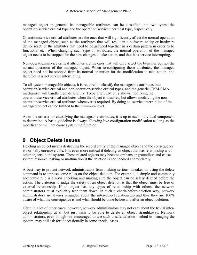
9 Object Delete Issues Deleting an object means destroying the record entity of the managed object and the consequence is normally unrecoverable. It is even more critical if deleting an object that has relationship with other objects in the system. Those related objects may become orphans or groundless and cause system resource leaking or malfunction if the deletion is not handled appropriately.
A best way to protect network administrators from making serious mistakes on using the delete command is to impose some rules on the object deletion. For example, a simple and commonly acceptable rule is always checking and making sure the object can be safely deleted before the action. The criterion to judge the safety of an object deletion is that the object must be free of external relationship. If an object has any types of relationship with others, the network administrators must explicitly tear them down. In such a check-before-deletion way, network administrators are always reminded about the inter-object relationship and thus they are 100% aware of what the consequence is and what should be done before and after an object deletion. Often in a lot of other cases, however, network administrators may not care about the trivial inter-object relationship at all but just wish to be able to delete an object straightaway. Network administrators, even though not encouraged to use such unsafe deletion method in managing the system, may still ask for it occasionally in some special cases.

A Reference Model of Management Plane
Conning Technology. All Rights Reserved. Page 12� of 37�
In order to on one hand keep the awareness of network administrators about the right object deletion procedure to guarantee the safety of the deletion, and on the other hand provide the capability that allows easy and straightforward one-step object deletion for occasional use, it is suggested to support two object deletion methods. Respectively, the two methods are:
• Normal delete: object can only be deleted after being explicitly set free from external relationship with other objects. In this case, network administrators are guided to go through the relationship teardown process of all related objects, and thus those related objects are always under the awareness of the network administrators and appropriate after-deletion action can be taken accordingly.
• Forced delete: object can be deleted immediately on receiving the deletion command. In this case, relationship with other objects will be cleaned up internally. However, network administrators may lose the knowledge about those related objects if they did not trace and remember them before the forced deletion. For this reason, it is not encouraged to use such a command if not absolutely necessary.
Normal deletion is the standard and recommended object deletion procedure. All network administrators are suggested to use this procedure as much as possible. Force deletion, on the other hand, aims to give the maximum freedom to the network administrators under the condition that they are fully aware of what they are doing and what the consequences are. It is strongly recommended not to use forced deletion procedure unless necessary.
10 About the collapsed CMM-CMA model As described in previous sections, each system manageable object is composed of a CMM portion and a CMA portion. The CMM portion residing on the system module is the centralized entity for the object to be accessed by various external user interfaces and internal inter-component interfaces. The CMA portion is normally responsible for the object related physical resource/device manipulation and operation. Thus the locations of various different CMAs are distributed all over the system, depending on where the physical resources/devices are. In most of the cases, the CMA portion of a manageable system object resides on an application module other than the system module. A completely separated CMM-CMA model is therefore required in these cases. In other cases if the CMA portion also resides on the system module, it is normally not necessary to physically separate the CMM and CMA any more. Or in other words the CMM and CMA can be viewed as collapsed together. Considering the different functionalities that a CMM and a CMA is respectively responsible for and the convenience and easiness of using a generic and unified CMM-CMA handling mechanism, it is still necessary to maintain the logical CMM and CMA concept in these cases. The generic CMM-CMA framework will provide a generic and unified CMM-CMA interface mechanism to cover both the normal and collapsed CMM-CMA cases.

A Reference Model of Management Plane
Conning Technology. All Rights Reserved. Page 13� of 37�
Figure 3 Normal distributed and collapsed CMM-CMA models
11 One CMM to multiple CMA relationship In most of the cases, a system manageable object is of a 1-CMM-to-1-CMA relationship. However, there still exist some cases that need to distribute the same set of object configuration data to multiple application modules. For example, some common service profile types of configurable objects are of this nature. There are two ways to handle such asymmetric CMM-CMA relationship.
• Duplicate the CMM portion to multiple copies and make it to be always of a 1-CMM-to-1-CMA symmetric relationship
• Implement a 1-CMM-to-multi-CMA asymmetric relationship handling mechanism. Compare the two, the tradeoff is between system resource usage and implementation simplicity. The first one clearly falls into the normal CMM-CMA handling mechanism and therefore is simple to implement. But resource wise it uses more than it need. The second one, on the other hand, can minimize the usage of system resources but implementation wise more complicated.
12 Configuration data distribution to CMA Configuration data distribution from CMM to CMA is the major function of the CMM-CMA interface. For the cases when CMM and CMA are both on the system module, this distribution may not be necessary or can be done easily using a function call type of synchronous action. For the cases when CMA resides on a different physical location from where the CMM is, either on a
Sys Module App. Module
CMM CMA
Sys Mpdule
CMM
CMA
Generic CMM-CMA interface
Generic CMM-CMA interface
Normal distributed CMM-CMA model
Collapsed CMM-CMA model

A Reference Model of Management Plane
Conning Technology. All Rights Reserved. Page 14� of 37�
different card or a different processor domain, the configuration data distribution has to be done using a message based asynchronous procedure. From a user prospect, actions can be taken to a manageable object are:
• Create: create the object instance and allocate required resources.
• Set: set or modify the object attributes, parameters and status etc.
• Enable: activate the object and trigger it to enter the functional active state.
• Disable: de-activate the object and bring it back to functional down state.
• Delete: de-allocate the occupied resources and delete the object instance.
• Get: obtain the attribute values, parameters and operational status of the managed object. Amongst the above 6 actions, the first 5 are closely related to the configuration data distribution between the CMM and CMA. An important issue related to the configuration data distribution from CMM to CMA is about the distribution timing. From the sample appearance of the object configuration logic, it is reasonable and easy to derive that configuration data distribution should be done on object creation and on every object parameter/attribute setting. If getting into the deeper design and implementation details, one can find that such a distribute-on-creation/setting logic is very questionable. What listed below explains the reasons.
• In order to distribute the configuration data to CMA, it is necessary first to know where the CMA should be. For the objects that can be created, there are the following cases:
o The object to be created is tightly coupled with a specific piece of resource/device on a specific location, such as an MAP entity on a specific application module. In this case, the location of the CMA is set by network administrators via configuration.
o The object to be created is a logical functional entity and can only be fully functional when it is bound to an object that has the physical location. IP port is an example of such object. It does not matter where to put the IP port entity, it can only be fully functional after bound to an Ethernet port. In this case, the location of the CMA is obtained through the bound object. Obviously, if the object binding is not done, it is not possible to know where to put the CMA.
• Most objects need to cooperate with other objects to provide the designed functionality. At the time to distribute the configuration data to CMA, it may be necessary to have all critical associated objects ready.
• Some of the object attributes are critical to the object functionality and may need to be grouped together and set following some pre-defined grouping-value pattern to maintain the object integrity.
• It is therefore necessary to have a specific time point to check the readiness of the configuration data distribution. At the time of an object creation, it is most likely not ready for doing so for reasons like either the location information is not available or key relationship with other objects has not been established yet.
Another configuration data distribution logic is distribute-on-enabling. Since at the time of object enabling,
• from a network administration point of view, the network administrator should have already finished setting all critical parameters, establishing key relationship and

A Reference Model of Management Plane
Conning Technology. All Rights Reserved. Page 15� of 37�
obtaining the physical location information etc critical configuration steps(or at least the network administrator think he/she does),
• Form an implementation point of view it is the best time point to check the readiness of the object configuration regarding all those key factors.
Therefore, distribute-on-enabling is the common configuration data distribution strategy to be adopted by the CMM-CMA mechanism. Each functional specific component using this mechanism for object provisioning and management is required to follow such a strategy in all cases unless special handling is absolutely needed. Figure 4 below illustrated this common configuration data distribution strategy.
Figure 4 Configuration data distribute-on-enabling strategy As the reverse logic of the distribute-on-enabling strategy, a withdraw-on-disabling strategy shall also be implemented on the CMM-CMA interface to
CLI/XML SNMPA CMM CMA
Create obj SNMP row set
CMM create
Alloc CMM
CMM create rply SNMP set rply
Obj attribute set
SNMP set
CMM set
Set CMM values
CMM set rply SNMP set rply
SNMP row set
Enable obj CMM enable
Enable CMM
CMM enable rply SNMP set rply Distribute to CMA
Create CMA, alloc
& activate resource
CMA rply
Update CMM
Obj not exist
Obj on CMM only
Obj exist on CMA

A Reference Model of Management Plane
Conning Technology. All Rights Reserved. Page 16� of 37�
• maintain the symmetry of the CMM-CMA interface implementation to keep the object status consistency so that any object management process can be always reversible and repeatable under the same/similar control logic,
• allow network administrator the freedom on manipulating the movement of physical location independent object through simple unbinding/binding operations
Figure 5 shows the configuration data withdraw-on-disabling strategy flow.
Figure 5 Configuration data withdraw-on-disabling strategy The distribute-on-enabling and withdraw-on-disabling strategies described above are general requirements between the CMM and CMA interface. Components using this interface are required to adopt these strategies in general configuration management cases. However, there are some special cases that still need the distribute-on-setting strategy. This is for supporting the minimum service interruption requirement as discussed earlier. In this case, for the object attributes that are runtime settable, the distribute-on-setting strategy is provided to support the modification of object parameters while object is enabled. Figure 6 shows the distribute-on-setting logic.
CLI/XML SNMPA CMM CMA
Disable obj SNMP row set
CMM disable
Disable CMM
CMM disable rply SNMP set rply Withdraw from CMA
de-activate & de-
alloc resource, delete
CMA rply
Update CMM
Obj exists on CMA
Obj on CMM only

A Reference Model of Management Plane
Conning Technology. All Rights Reserved. Page 17� of 37�
Figure 6 Configuration data distribute-on-setting strategy
13 Serializing the configuration event handling As in most system management plane architecture, various external configuration interfaces, including CLI, XML and SNMP based open interface, are to be unified to use SNMP. Since there is no session/transaction concept in SNMP handling, it is necessary to handle and reply all the SNMP requests in a serial manner. Since SNMP agent and CM are both on the system module, the interface between them can be done using the tight-coupled direct function calls and thus it natively possesses the required serial handling nature. The interface between CMM and CMA, however, is message based loose-coupled in most of the cases. In SNMP, there are basically two types of commands to handle, SNMP set and SNMP get. For an SNMP set request, as long as the parameter to be set reaches the CMM part of the managed object, corresponding SNMP set reply can be triggered to unblock the succeeding requests if any. For an SNMP get request, there are two cases. The first is that the parameter to be gotten is an administrative one that can be retrieved from the CMM part of the managed object. The second is the case that the parameter is an operational value and need to be gotten from CMA. Figure 7, Figure 8 and Figure 9 show the serial handling processes of the SNMP set and two SNMP get cases respectively.
CLI/XML SNMPA CMM CMA
Obj attribute set SNMP set
CMM set
Set CMM values
SNMP set rply Distribute to CMA
Update CMA
CMA rply
Obj exist on CMA
CMM set rply
A Reference Model of Management Plane
Conning Technology. All Rights Reserved. Page 18� of 37�
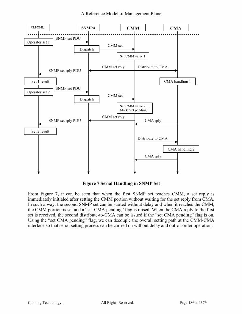
Figure 7 Serial Handling in SNMP Set From Figure 7, it can be seen that when the first SNMP set reaches CMM, a set reply is immediately initialed after setting the CMM portion without waiting for the set reply from CMA. In such a way, the second SNMP set can be started without delay and when it reaches the CMM, the CMM portion is set and a “set CMA pending” flag is raised. When the CMA reply to the first set is received, the second distribute-to-CMA can be issued if the “set CMA pending” flag is on. Using the “set CMA pending” flag, we can decouple the overall setting path at the CMM-CMA interface so that serial setting process can be carried on without delay and out-of-order operation.
CLI/XML SNMPA CMM CMA
SNMP set PDU
CMM set
Set CMM value 1
CMM set rply SNMP set rply PDU
CMA rply
Distribute to CMA
Operator set 1
Dispatch
Set 1 result
SNMP set PDU
CMM set
Set CMM value 2 Mark “set pending”
CMM set rply SNMP set rply PDU
Operator set 2
Dispatch
Set 2 result
CMA handling 1
Distribute to CMA
CMA handling 2
CMA rply

A Reference Model of Management Plane
Conning Technology. All Rights Reserved. Page 19� of 37�
Figure 8 Serial Handling in SNMP Get (Administrative data case) In “getting administrative data” case as shown in Figure 8, request can be served without going to the CMA.
Figure 9 Serial Handling in SNMP Get (Operational data case) In “getting operational data” case as shown in Figure 9, get reply can only be triggered when receives the get reply from CMA.
CLI/XML SNMPA CMM CMA
SNMP get PDU
CMM get
get value
CMM get rply SNMP get rply PDU
Operator get
Dispatch
Get result
CLI/XML SNMPA CMM CMA
SNMP get PDU
CMM get
get value
CMM get rply SNMP get rply PDU
Operator get
Dispatch
Get result
Get from CMA
CMA get rply

A Reference Model of Management Plane
Conning Technology. All Rights Reserved. Page 20� of 37�
For both the two “get” cases shown in Figure 8 and Figure 9, succeeding requests are blocked before get reply returns.
14 Relationship between managed objects Most manageable objects will have some kind of relationship with others to provide the designed functionalities. Normally, relationships between any two objects can be classified into binding relationship and parent-child relationship.
Binding relationship is between objects without belongingness and they are linked together to accomplish certain functionalities. In most of the cases, objects with binding relationship can exist on independently and thus can be created or deleted independently. Parent-child relationship is between objects that one belongs to another. For such types of relationship, child cannot live on its own without a parent object. For objects linked together by either one of the above relationships, they are always mutual-influential. Therefore, appropriate notification mechanism is necessary for them to inform each other whenever needed. For example, when the administrative or operational status of an object changed, all its related objects should be informed via such notification mechanism so that appropriate action can be taken to the affected objects. For the reason that the CMM portions of all manageable objects are centralized and managed by a single CM component on the system module, CMM is therefore always the best place to collect and exchange object status information. In order to make the notification mechanism unified and simplified, only one unique
notification path is recommended, that is the CMA portion of an object always report its status change to its CMM and the CMM portion is responsible for notifying all other CMM portions of affected objects, the
affected objects can then take appropriate actions after receiving such notification. Figure 10 below shows the notification process between related objects.
Figure 10 Notification mechanism between related objects
Obj1 CMM
Obj2 CMM
Obj1 CMA
Obj2 CMA Obj2 Resource 1 2
3
Obj1 Resource 4 5
1. Resource of object 2 reported a status change 2. CMA of object 2 send notification to its CMM 3. CMM of object 2 notify the CMM of its related object 1 4. CMM of object 1 take action to its CMA 5. CMA of object 1 take action to its resource

A Reference Model of Management Plane
Conning Technology. All Rights Reserved. Page 21� of 37�
The relationship between any two manageable objects is to be explicitly established by a network administrator through issuing a binding or adding command. In implementation, the two affected objects should exchange private handler information with each other via registration or reservation. The private handler information exchanged should be able to uniquely address the related object. Since the CMM portions of the two objects are running in the same thread, the registration or reservation can be done via direct function call. Figure 11 shows an example of the inter-object relationship establishing process.
Figure 11 Inter-object relationship establishing process
15 Sanity and Integrity Check on Object Managing When doing row actions to an object (creating, enabling, disabling and deleting) or setting some of its parameters, it is necessary to do some checks before applying the actions so that the parameters to be set are within the predefined reasonable ranges or the object are ready for the required row actions.
Checks to be done at the CMM include:
• Basic parameter value range check, to check if the value to be set is within the predefined value range.
• Object parameter combination checks, to check if the values of a group of parameters are of the legal combinations.
• Row action eligibility checks, to check if all object parameters are ready for the required row action. For example, some key parameters of an object must be appropriately set or key relationship with other objects must be established before enabling the object.
• Parameter set-ability check, to check if the parameter can be set under the current condition. For example, some parameters can only be set when an object is in disabled state and some parameters can be set on run at any time.
Administrator Object A (CMM) Object B (CMM)
Bind object A To object B
Object A calls registration or reservation function of object B with self addressing infor.
Save information of object A and returns self addressing information.
Save information of object B
Function call
Relationship established

A Reference Model of Management Plane
Conning Technology. All Rights Reserved. Page 22� of 37�
These checks can be done at two stages. The first one is to use the pre-set test utility provided by most SNMP agent stacks. This utility allows tests on all variable-bindings in an SNMP set PDU before triggering the set function. Having this, the majority of the required checks can be done. For the cases that cannot be tested before setting, there is still the second chance to do checks at the parameter setting time. Figure 12, Figure 13 and Figure 14 below show the test-and-set sanity and integrity check procedures.
Figure 12 Test-and-set sanity and integrity check procedure (succeeds)
Figure 13 Test-and-set sanity and integrity check procedure (fails at setting)
CLI/XML SNMPA CMM CMA
Set obj parameters
SNMP PDU
Test dispatch
Test functions Test succeeds
Set
dispatc Set functions Set fails
SNMP rply (fails)
CLI/XML SNMPA CMM CMA
Set obj parameters
SNMP PDU
Test dispatch
Test functions Test succeeds
Set
dispatc Set functions Set succeeds
SNMP rply (succeeds) Set CMA
CMA reply

A Reference Model of Management Plane
Conning Technology. All Rights Reserved. Page 23� of 37�
Figure 14 Test-and-set sanity and integrity check procedure (fails at testing)
16 CM operation control flows
16.1 Control Flow of CM Object Creation
Figure 15 Object creation control flow (succeeds)
CLI/XML SNMPA CMM CMA
Set obj parameters
SNMP PDU
Test dispatch
Test functions Test fails
SNMP rply (fails)
CLI/XML SNMP CMM CMA
Administrator
Create obj : name
Generate ifindex
Dispatch to CMM
1. Make sure name and ifindex unique, 2. alloc control block 3. update name DB 4. update ifindex hash table 5. send create reply SNMP reply
CLI/XML returns ok
Creation success CMM returns OK
SNMP PDU
Dispatch function

A Reference Model of Management Plane
Conning Technology. All Rights Reserved. Page 24� of 37�
Figure 16 Object creation control flow (fails at CMM)
16.2 Control Flow of CM Object Enabling
Figure 17 Object enabling control flow (succeeds)
CLI/XML SNMP CMM CMA
Administrator
Create obj : name
Generate ifindex
Dispatch to CMM
Ifindex duplication or other errors found
SNMP reply
CLI/XML returns error
Creation failed
CMM returns error
Free ifindex
SNMP PDU
Dispatch function
CLI/XML SNMP CMM CMA
Administrator
Enable object
Set row status to enabled
Dispatch to CMM
Make sure object can be enabled SNMP reply
CLI/XML returns ok
Enabling success CMM returns OK
SNMP PDU
Dispatch function
Distribute to CMA
CMA handling, alloc resource etc
CMA reply
Status update

A Reference Model of Management Plane
Conning Technology. All Rights Reserved. Page 25� of 37�
Figure 18 Object enabling control flow (fails)
16.3 Control Flow of CM Object Disabling
Figure 19 Object disabling control flow (succeeds)
CLI/XML SNMP CMM CMA
Administrator
Enable object
Set row status to enabled
Dispatch to CMM
Make sure object can be enabled SNMP reply
CLI/XML returns error
Enabling failed CMM returns error
SNMP PDU
Dispatch function
CLI/XML SNMP CMM CMA
Administrator
Disable object
Set row status to disabled
Dispatch to CMM
Make sure object can be disabled SNMP reply
CLI/XML returns ok
Disabling success CMM returns OK
SNMP PDU
Dispatch function
Withdraw from CMA
CMA handling, free resource, delete local entry etc
CMA reply
Status update

A Reference Model of Management Plane
Conning Technology. All Rights Reserved. Page 26� of 37�
Figure 20 Object disabling control flow (fails)
16.4 Control Flow of CM Object Deleting
Figure 21 Object deleting control flow (success)
CLI/XML SNMP CMM CMA
Administrator
Disable object
Set row status to disabled
Dispatch to CMM
Make sure object can be disabled SNMP reply
CLI/XML returns error
Disabling failed CMM returns error
SNMP PDU
Dispatch function
CLI/XML SNMP CMM CMA
Administrator
Delete object
Set row status to destroy
Dispatch to CMM
1. Make sure the obj can be deleted, 2. delete the object entry 3. remove name from DB
SNMP reply
CLI/XML returns ok
Object deleted
CMM returns OK
Free ifindex
SNMP PDU
Dispatch function

A Reference Model of Management Plane
Conning Technology. All Rights Reserved. Page 27� of 37�
Figure 22 Object deleting control flow (failed)
Figure 23 Object force deleting control flow
CLI/XML SNMP CMM CMA
Administrator
Delete object
Set row status to destroy
Dispatch to CMM
Make sure the obj can be deleted
SNMP reply
CLI/XML returns error
Object deleting failed
CMM returns error
SNMP PDU
Dispatch function
CLI/XML SNMP CMM CMA
Administrator
Force delete obj.
Set row status to destroy, with force delete flag
Dispatch to CMM
1. cleanup all relationship, 2. delete the object entry 3. remove name from DB
SNMP reply
CLI/XML returns ok
Object deleted
CMM returns OK
Free ifindex
SNMP PDU
Dispatch function

A Reference Model of Management Plane
Conning Technology. All Rights Reserved. Page 28� of 37�
16.5 Control Flow of CM Object Setting
Figure 24 Object setting control flow (succeeds, object in disabled state)
Figure 25 Object setting control flow (succeeds, object in enabled state)
CLI/XML SNMP CMM CMA
Administrator
set object attribute
SNMP set
Dispatch to CMM
Set the object attribute
SNMP reply
CLI/XML returns ok
Set success CMM returns ok
SNMP PDU
Dispatch function
Object is in disabled state
CLI/XML SNMP CMM CMA
Administrator
set object attribute
SNMP set
Dispatch to CMM
1. Make sure the attribute can be set in enabled state 2. Set the object attribute 3. distribute setting to CMA SNMP reply
CLI/XML returns ok
Set success CMM returns ok
SNMP PDU
Dispatch function
Object is in enabled state
Distribute to CMA
Set CMA
CMA reply
A Reference Model of Management Plane
Conning Technology. All Rights Reserved. Page 29� of 37�
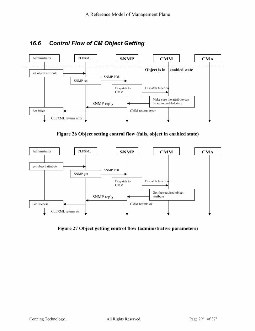
16.6 Control Flow of CM Object Getting
Figure 26 Object setting control flow (fails, object in enabled state)
Figure 27 Object getting control flow (administrative parameters)
CLI/XML SNMP CMM CMA
Administrator
set object attribute
SNMP set
Dispatch to CMM
Make sure the attribute can be set in enabled state SNMP reply
CLI/XML returns error
Set failed CMM returns error
SNMP PDU
Dispatch function
Object is in enabled state
CLI/XML SNMP CMM CMA
Administrator
get object attribute
SNMP get
Dispatch to CMM
Get the required object attribute SNMP reply
CLI/XML returns ok
Get success CMM returns ok
SNMP PDU
Dispatch function
A Reference Model of Management Plane
Conning Technology. All Rights Reserved. Page 30� of 37�
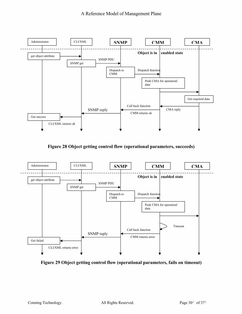
Figure 28 Object getting control flow (operational parameters, succeeds)
Figure 29 Object getting control flow (operational parameters, fails on timeout)
CLI/XML SNMP CMM CMA Administrator
get object attribute
SNMP get
Dispatch to CMM
Peek CMA for operationl data
SNMP reply
CLI/XML returns ok
Get success
CMM returns ok
SNMP PDU
Dispatch function
Object is in enabled state
Get required data
CMA reply Call back function
CLI/XML SNMP CMM CMA Administrator
get object attribute
SNMP get
Dispatch to CMM
Peek CMA for operationl data
SNMP reply
CLI/XML returns error
Get failed
CMM returns error
SNMP PDU
Dispatch function
Object is in enabled state
Call back function Timeout
A Reference Model of Management Plane
Conning Technology. All Rights Reserved. Page 31� of 37�
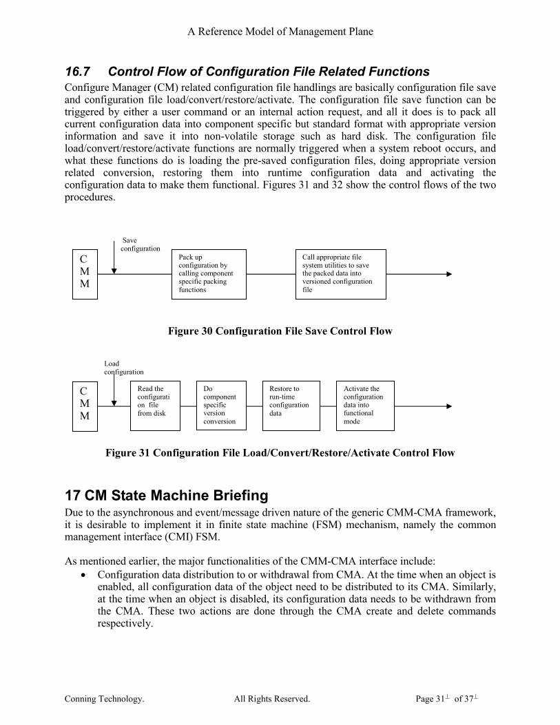
16.7 Control Flow of Configuration File Related Functions Configure Manager (CM) related configuration file handlings are basically configuration file save and configuration file load/convert/restore/activate. The configuration file save function can be triggered by either a user command or an internal action request, and all it does is to pack all current configuration data into component specific but standard format with appropriate version information and save it into non-volatile storage such as hard disk. The configuration file load/convert/restore/activate functions are normally triggered when a system reboot occurs, and what these functions do is loading the pre-saved configuration files, doing appropriate version related conversion, restoring them into runtime configuration data and activating the configuration data to make them functional. Figures 31 and 32 show the control flows of the two procedures.
Figure 30 Configuration File Save Control Flow
Figure 31 Configuration File Load/Convert/Restore/Activate Control Flow
17 CM State Machine Briefing Due to the asynchronous and event/message driven nature of the generic CMM-CMA framework, it is desirable to implement it in finite state machine (FSM) mechanism, namely the common management interface (CMI) FSM. As mentioned earlier, the major functionalities of the CMM-CMA interface include:
• Configuration data distribution to or withdrawal from CMA. At the time when an object is enabled, all configuration data of the object need to be distributed to its CMA. Similarly, at the time when an object is disabled, its configuration data needs to be withdrawn from the CMA. These two actions are done through the CMA create and delete commands respectively.
CMM
Save configuration
Pack up configuration by calling component specific packing functions
Call appropriate file system utilities to save the packed data into versioned configuration file
CMM
Load configuration
Read the configuration file from disk
Do component specific version conversion
Restore to run-time configuration data
Activate the configuration data into functional mode

A Reference Model of Management Plane
Conning Technology. All Rights Reserved. Page 32� of 37�
• Object operation status reporting to CMM. When the operation status of an object changed for whatever reasons, its CMA needs to notify its CMM about the change through a CMA event notify.
• Object function enabling or disabling. When any one of the associated objects of a managed object is out of or back into functional, the managed object is notified via the inter-object CMM notification mechanism. Up on receiving such notification, the managed object may need to be brought down or up if the notification is critical to its operation. CMA enable and disable commands are used for this purpose.
Illustrating in flow chart, the above events and corresponding actions are shown in Figure 32.
Figure 32 CMM-CMA interface commands and replies
17.1 CMI FSM states definition
17.1.1 CMI FSM states definitions
CMI FSM defines the following valid states:
• NULL state, o the very initial state of an object when the CMM portion is created or o received a CMA delete reply (CMA_DELETE_RPY), or o timeout on waiting for the CMA_DELETE_RPY
CMM CMA
Enable
Distribute configuration data (CMA_CREATE_CMD)
Alloc & enable object CMA_CREATE_RPY
Associated object down CMA_DISABLE_CMD
Disable object CMA_DISABLE_RPY
Associated object up
CMA_ENABLE_CMD
Enable object CMA_ENABLE_RPY
Disable Withdraw configuration data (CMA_DELETE_CMD)
Disable &dealloc object CMA_DELETE_RPY

A Reference Model of Management Plane
Conning Technology. All Rights Reserved. Page 33� of 37�
o CMA not exist in this state
• CREATE_WAIT state, o received CMM enabling command (CMM_ENABLE_CMD), o sent CMA create command (CMA_CREATE_CMD) and o is waiting for the create reply (CMA_CREATE_RPY) from CMA. o CMA not exist in this state
• NOT_READY state, o received a failed CMA create reply (CMA_CREATE_RPY) in CREATE_WAIT
state or o timeout on waiting for CMA create reply (CMA_CREATE_RPY) in
CREATE_WAIT state. o CMA not exist in this state
• DISABLE_WAIT state, o sent CMA_DISABLE_CMD and o is waiting for the CMA_DISABLE_RPY. o CMA exist this state
• DISABLED state, o received CMA_DISABLE_RPY in DISABLE_WAIT state or o received failed CMA_ENABLE_RPY in ENABLE_WAIT state or o timeout on waiting for the CMA_ENABLE_RPY or o timeout on waiting for the CMA_DISABLE_RPY. o CMA exist this state
• ENABLE_WAIT state, o sent CMA_ENABLE_CMD in DISABLED state and o is waiting for the CMA_ENABLE_RPY. o CMA exist this state
• ENABLED state, o Received success CMA_CREATE_RPY from CMA in CREATE_WAIT state, or o received success CMA_ENABLE_RPY from CMA in ENABLE_WAIT state. o CMA exist in this state
• DELETE_WAIT state, o Received CMM disabling command o Sent CMA_DELETE_CMD o Is waiting for the CMA_DELETE_RPY o CMA exist in this state
17.1.2 CMI FSM events definitions
CMI FSM defines the following events and they can be classified into three categories, respectively, CMM events, CMA events and CMI internal events.
• CMM_ENABLE_CMD, command from a network administrator for enabling an object instance. This command will trigger the sending of CMA_CREATE_CMD to CMA.
• CMM_DISABLE_CMD, command from a network administrator for disabling an object instance. This command will trigger the sending of CMA_DELETE_CMD to CMA.
• CMM inter-object notification mechanism triggered CMA_ENABLE_CMD to enable the object CMA.

A Reference Model of Management Plane
Conning Technology. All Rights Reserved. Page 34� of 37�
• CMM inter-object notification mechanism triggered CMA_DISABLE_CMD to disable the object CMA.
• CMM_SET_CMD, command to trigger the parameter set to CMA,
• CMM_GET_CMD, command to trigger the parameter get from CMA,
• CMA_CREATE_RPY, CMA create reply event.
• CMA_ENABLE_RPY, CMA enable reply event.
• CMA_DISABLE_RPY, CMA disable reply event.
• CMA_DELETE_RPY, CMA delete reply event.
• CMA_SET_RPY, CMA set reply event,
• CMA_GET_RPY, CMA get reply event,
• CMA_NOTIFY, CMA notify event,
• GET_TOMEOUT, timeout event for CMA get,
• TIMEOUT, timeout event for all WAIT states,
• INT_CLR, CMI internal clear event,
• MGMT_CLR, GMI management clear event.
18 Using MIB compiler to auto-generate executable MIB/component specific source codes
With the help of the customized MIB compiler, all MIB or component specific CMM-CMA handling source codes including structure and object class definitions, majority of CMM side of handling source codes and a significant portion of CMA side handling source codes, CMM-CMA interfacing messages and delivery logic source codes can all be auto-generated. On top of these auto-generated source codes, developers only need very limited amount of necessary component specific customization to make the fully functional management plane. Besides, CLI commands definitions, CLI show screen scripts, XML presentation etc. user interface files can also be auto-generated with appropriate modification on the MIB compiler. The automation can help save a lot of engineers’ effort in development the system management plane, and at the meantime maintains high consistency for all managed objects and therefore saves maintenance efforts as well.
19 Other aspects of the management plane framework
19.1 Data collection for system operation monitoring Some carrier may ask for the functionality that allows periodic or manual triggered system status and stats collection to monitor the network operation and plan the network level of load balancing. This requires all configured objects report their status and stats on request or on a periodic basis. The CMM-CMA frame work covers this functionality together with the auto-generate source codes.

A Reference Model of Management Plane
Conning Technology. All Rights Reserved. Page 35� of 37�
19.2 Configuration delta change notification to external EMS When a network administrator uses both CLI and GUI to manage a system, there is a need to synchronize with the external EMS configuration database when CLI is used to modify the system configuration. This is the so called delta change notification mechanism. This mechanism can also be provided by the CMM-CMA framework together with the component specific auto-generated codes.

A Reference Model of Management Plane
Conning Technology. All Rights Reserved. Page 36� of 37�

A Reference Model of Management Plane
Conning Technology. All Rights Reserved. Page 37� of 37�