
Management Control System (MCS) User Manual · Courier New font indicates literal input to be typed...
81
DIRECTV Confidential Management Control System (MCS) User Manual DIRECTV RESIDENTIAL EXPERIENCE (Hospitality Solutions)
Transcript of Management Control System (MCS) User Manual · Courier New font indicates literal input to be typed...

DIRECTV Confidential
Management Control System (MCS) User Manual
DIRECTV RESIDENTIAL EXPERIENCE (Hospitality Solutions)

DIRECTV Confidential
(Rev. 2.1)
November 27, 2013
DIRECTV Confidential
This document contains proprietary information and except with
written permission of DIRECTV such information shall not be
published and this document shall not be duplicated or distributed,
in whole or part

DIRECTV Residential Experience MCS User Manual
Rev. 2.1 DIRECTV Confidential Page 3 of 81
REVISION HISTORY
Revision Date of Issue Author Scope
0.1 August 11, 2011 M. Geier Initial version
0.2 August 24, 2011 R. Pezeshki Added the missing content
0.3 August 25, 2011 R. Pezeshki and R. Tatem
Document-wide edits
0.4 March 5, 2012 D. Chen Adding Phase 2 Information
1.0 March 23, 2012 D. Chen Added LCI Content Format Guidelines
1.1 April 15, 2012 R. Pezeshki Added PMS Configuration Setting and Serial Connection Pin-outs
1.1 April 23, 2012 R. Pezeshki Added LCI Troubleshooting Updated the network interfaces file to match the latest release Added an updated screen shot of MCS log showing PMS Filtering Updated Network Topology Diagrams Updated Email Alrets screen shots with SMTP Configuration Setting. Updated LCI Local Channels screen shot
2.0 November 8, 2012
D. Chen Updated for MCS v3.x Added Setup Section Rephrased most 2.x specific text for 3.x
2.1 November 27, 2013
R. Pezeshki, D.Chen
Updated for MCS v3.17 Updated installation process for Ubuntu 12.04 Corrected overall formatting

DIRECTV Residential Experience MCS User Manual
Rev. 2.1 DIRECTV Confidential Page 4 of 81
Table Of Contents
Section Page
1 Introduction ............................................................................................................................. 9
1.1 Purpose .......................................................................................................................................... 9
1.2 Intended Audience ........................................................................................................................ 9
1.3 Problem Reporting ..................................................................................................................... 10
1.4 Conventions ................................................................................................................................. 10
1.5 Definitions and Acronyms ......................................................................................................... 10
2 Installation of MCS System .................................................................................................. 11
2.1 Staging Installation ..................................................................................................................... 11
2.1.1 Alcatel Switch Configuration ................................................................................... 11
2.1.2 MCS Server Ubuntu Linux Install ............................................................................ 12
2.1.3 Installing the MCS Software ..................................................................................... 13
2.1.4 Verifying Complete MCS installation ...................................................................... 14
2.1.5 Setting up User Accounts.......................................................................................... 15
2.1.5.1 Changing the Password of “mcsadmin” and “user” ........................................... 15
2.1.5.2 Creating New Accounts for End Users .............................................................. 15
2.1.6 Use MCS to set SBB Managed Mode....................................................................... 16
2.1.7 Setting Property Information on MCS ...................................................................... 17
2.1.8 Setting a Property Logo on SBBs ............................................................................. 17
2.1.9 Configuring Hotel Channel Lists on SBBs ............................................................... 18
2.1.10 Configuring Hotel Defaults on SBBs .................................................................... 20
2.1.11 Preparing Installation Spreadsheet ........................................................................ 21
2.2 Property Onsite Installation ...................................................................................................... 22
2.2.1 MCS Server and Network installation ...................................................................... 22
2.2.2 SBB Room Installation ............................................................................................. 22
3 In-Room Verification ............................................................................................................ 23
3.1 Import Receiver information into MCS ................................................................................... 23
4 MCS Web User Interface ...................................................................................................... 25
4.1 Login ............................................................................................................................................ 25
4.2 Receiver Management List ........................................................................................................ 25

DIRECTV Residential Experience MCS User Manual
Rev. 2.1 DIRECTV Confidential Page 5 of 81
4.2.1 Navigating the MCS receiver list .............................................................................. 27
4.2.2 Updates to the Receiver List ..................................................................................... 27
4.2.3 Receiver information ................................................................................................ 28
4.2.3.1 Room .................................................................................................................. 28
4.2.3.2 RID and CAM .................................................................................................... 28
4.2.3.3 IP Address .......................................................................................................... 28
4.2.3.4 Software Version ................................................................................................ 28
4.2.3.5 Signal Strength ................................................................................................... 28
4.2.3.6 Hardware Model ................................................................................................. 28
4.2.3.7 Managed Mode Status ........................................................................................ 28
4.2.3.8 Default Settings Status ....................................................................................... 29
4.2.3.9 Active Status ...................................................................................................... 29
4.2.3.10 Battery Status ..................................................................................................... 29
4.2.3.11 Switch Type........................................................................................................ 29
4.2.3.12 SWM Channels .................................................................................................. 29
4.2.3.13 SWM Serial Number .......................................................................................... 29
4.2.4 Expanded Receiver Information ............................................................................... 29
4.3 Configuring and Assigning Channel List ................................................................................. 30
4.3.1 Configuring Channel List: ........................................................................................ 30
4.3.1.1 Displaying or Editing a Channel List ................................................................. 31
4.3.1.2 Deleting a Channel List ...................................................................................... 31
4.3.2 Assigning Channel List: ............................................................................................ 32
4.4 Configuring and Assigning Defaults ......................................................................................... 32
4.4.1 Configuring Default Settings .................................................................................... 32
4.4.2 Assigning Default Settings ....................................................................................... 33
4.5 Sending MCS Commands .......................................................................................................... 34
4.5.1 Reset Defaults ........................................................................................................... 35
4.5.2 Set Room Name/Number .......................................................................................... 37
4.5.3 Check-in .................................................................................................................... 37
4.5.4 Check-out .................................................................................................................. 38
4.6 Setting and Assigning Groups ................................................................................................... 38
4.6.1 Receiver Grouping .................................................................................................... 38

DIRECTV Residential Experience MCS User Manual
Rev. 2.1 DIRECTV Confidential Page 6 of 81
4.6.2 The Unassigned Group ............................................................................................. 39
4.6.3 Creating a New group ............................................................................................... 39
4.6.4 Moving Receivers In-Between Groups ..................................................................... 39
4.6.5 Removing a Group .................................................................................................... 39
4.7 View Logs .................................................................................................................................... 40
5 Administrator Settings ........................................................................................................... 41
5.1 Administrative SBB List ............................................................................................................ 41
5.1.1 Set Management Mode ............................................................................................. 41
5.1.2 Set PMS ID ............................................................................................................... 41
5.1.3 Delete SBB................................................................................................................ 42
5.1.4 Reset Defaults ........................................................................................................... 42
5.2 User Management ....................................................................................................................... 42
5.3 Property Information ................................................................................................................. 43
5.3.1 Property Location...................................................................................................... 43
5.3.1.1 Format ................................................................................................................ 43
5.3.1.2 During Installation.............................................................................................. 43
5.3.2 Property Logo ........................................................................................................... 43
5.4 Import & Export......................................................................................................................... 45
5.4.1 Export User List ........................................................................................................ 45
5.4.2 Export Receiver List ................................................................................................. 45
5.4.3 Export Logs ............................................................................................................... 45
5.4.4 Export Defaults ......................................................................................................... 45
5.4.5 Export Channel Lists................................................................................................. 45
5.4.6 Import User List ........................................................................................................ 45
5.4.7 Import Receiver List ................................................................................................. 45
5.4.8 Import Defaults ......................................................................................................... 45
5.4.9 Import Channel Lists................................................................................................. 46
5.4.10 Import New Receiver Installation CSV ................................................................. 46
5.5 Local Channels ........................................................................................................................... 46
5.5.1 Local Channel Content Format Guidelines............................................................... 46
5.5.2 Create Video Source ................................................................................................. 47
5.5.2.1 Add Video Source from File .............................................................................. 47

DIRECTV Residential Experience MCS User Manual
Rev. 2.1 DIRECTV Confidential Page 7 of 81
5.5.2.2 Add Video Source from Network Camera ......................................................... 48
5.5.3 Create Local Channel ................................................................................................ 49
5.5.4 Set Channel Numbers ............................................................................................... 50
5.6 E-mail Alerts ............................................................................................................................... 50
5.7 Services Status ............................................................................................................................ 53
5.8 PMS Interface ............................................................................................................................. 53
5.8.1 Connectivity between the Property Management System and the MCS .................. 53
5.8.2 PMS Serial Port Configuration ................................................................................. 55
5.9 Parental Control Configuration ................................................................................................ 55
6 Setup Section ......................................................................................................................... 57
6.1 Dealer Information ..................................................................................................................... 57
6.2 Network ....................................................................................................................................... 58
6.3 PMS.............................................................................................................................................. 59
6.4 Verification .................................................................................................................................. 60
6.5 System Update ............................................................................................................................ 61
6.6 Reboot .......................................................................................................................................... 61
7 Troubleshooting DRE Problems ........................................................................................... 62
7.1 MCS Receiver List Updating ..................................................................................................... 62
7.1.1 The MCS screen does not appear to be refreshing ................................................... 62
7.1.2 I just added/fixed/changed a receiver and it is not showing in the list ..................... 62
7.1.3 A receiver is offline but still showing “alive” in the MCS receiver list ................... 62
7.2 Debugging LCI ........................................................................................................................... 63
7.2.1 Debugging LCI Content ............................................................................................ 63
7.2.2 Debugging DRE Network and LCI Channel List ..................................................... 63
7.3 Debugging SBB Issues ................................................................................................................ 64
7.3.1 Verify SBBs are set for Hospitality .......................................................................... 64
7.3.2 Verify SBBs are activated ......................................................................................... 64
7.3.3 Verify SBBs are active and displaying video ........................................................... 64
7.3.4 Verify the SBB connection to the IDF switch .......................................................... 64
7.3.5 Verify MCS Configuration ....................................................................................... 64
7.4 Debugging .................................................................................................................................... 65
7.4.1 Verifying MCS Server Network Configuration ........................................................ 65
7.4.2 Verifying the Switch Configuration .......................................................................... 65

DIRECTV Residential Experience MCS User Manual
Rev. 2.1 DIRECTV Confidential Page 8 of 81
7.4.2.1 Verify Port Configuration on (MDF) ALU6400 ................................................ 65
7.4.2.2 Verify Port Configuration on IDF switches ....................................................... 66
7.4.3 Verifying MCS DHCP Server Configuration ........................................................... 67
7.4.4 Verifying MCS Services ........................................................................................... 68
7.4.4.1 Verifying the MCS Discovery Service .............................................................. 69
7.4.4.2 Verifying the Sous-SHEF service ...................................................................... 69
7.4.5 Verifying Apache and Web Services ........................................................................ 71
8 Linux Commands and Tutorial ............................................................................................ 72
9 Setting Windows Laptop for Support .................................................................................... 73
10 Using Wireshark ................................................................................................................ 74
10.1 Things to Look for in Wireshark ........................................................................................... 75
11 Appendix ............................................................................................................................. 76
11.1 DRE System Network Topology ............................................................................................ 76
11.1.1 DIRECTV’s Recommended Network Topology (Option 1) ................................. 76
11.1.2 Option 2 ................................................................................................................. 78
11.1.3 Option 3 ................................................................................................................. 80
List of Tables
Table 1: Glossary and Acronyms .................................................................................................. 10
Table 2: Pin numbers for DB-25 and RJ45. (Note: only pins 2, 3, and 7 are need) .................... 54

DIRECTV Residential Experience MCS User Manual
Rev. 2.1 DIRECTV Confidential Page 9 of 81
1 Introduction
1.1 Purpose
This document is intended for use by authorized DIRECTV Dealers and DIRECTV distributors
to explain the features of the Management Control System.
1.2 Intended Audience
This document is intended for multiple purposes and user types. Distributors will create a
package solution containing MCS and will need to understand how MCS works at both a
functional level and a technical level. Distributors should use this document as a starting point
for understanding MCS and pass on this document to individual Dealers/Installers. Dealers and
Installers should use this document to assist in the installation, configuration and
troubleshooting of MCS on site at a hospitality property. Hotel staff or ‘users’ should use this
document as reference for operating MCS and performing basic operations.

DIRECTV Residential Experience MCS User Manual
Rev. 2.1 DIRECTV Confidential Page 10 of 81
1.3 Problem Reporting
For any problems, bugs or issues you encounter, please contact us at:
http://www.dresupport.com/
1.4 Conventions
Items in “quotation marks” refer to interface buttons, links or labels on the MCS interface or
literal inputs to be typed.
Courier New font indicates literal input to be typed with
modifications as needed for your configuration or literal output
to be verified.
1.5 Definitions and Acronyms
Some of these terms and abbreviations are used in this document:
Table 1: Glossary and Acronyms
Term Definition
DRE DIRECTV Residential Experience
MCS Management Control Server
SBB Set Back Box (Set-top Box for DRE). Also called a receiver.

DIRECTV Residential Experience MCS User Manual
Rev. 2.1 DIRECTV Confidential Page 11 of 81
2 Installation of MCS System This section covers steps to configure and install MCS system for the DRE system. The
installation should be done in two parts – staging and on-site installation.
2.1 Staging Installation
The first step in installation is to stage and setup the switches, SBBs and Linux server in an
environment where you have access to an internet connection, DIRECTV activation services, a
satellite connection and Linux software.
2.1.1 Alcatel Switch Configuration
Each IDF switch must be configured by copying a configuration file or manually adjusting
settings to the switches. To configure the IDF switches (Alcatel 6250):
Connect a notebook computer or the MCS machine to the serial console port of the IDF switch.
Use a terminal communication program such as minicom or HyperTerminal to connect to the
switch. Settings should be 9600 8N1 with hardware and software flow control off
Login to the switch. The default username is "admin" and the default password is "switch"
Review and edit the IDF switch configuration file provided by Alcatel based on the property’s
network configuration.
The IDF switches will be on the 10.129.8.xxx network and the 172.16.1.xxx network.
We recommend setting the IP addresses to 10.129.8.2 and 172.16.1.2 for the first IDF switch,
10.129.8.3 and 172.16.1.3 for the second, and so forth. 10.129.8.1/172.16.1.1 is saved for the
MDF switch and 172.16.1.11 is saved for the MCS machine.
NOTE: The MCS machine by default is assigned to 172.16.1.11 so make sure you
do not use this IP for the IDF switches unless you are going to reconfigure Linux
networking and DHCP on the MCS machine.
We recommend setting the default prompt for each switch so that when configuring the switch
it is easy to identify which switch is which. To do so, use the command “session prompt default
"Desired IDF Switch name >>" ”
Copy/paste the switched configuration file into the terminal to set recommended settings.
Type "write memory" and then "copy working certified" to save your changes on the switch.
Before restarting, review the changes by using the command; show configuration snapshot.
Type “reloads" and “confirm” in order to restart the switch.
DIRECTV Residential Experience MCS User Manual
Rev. 2.1 DIRECTV Confidential Page 12 of 81
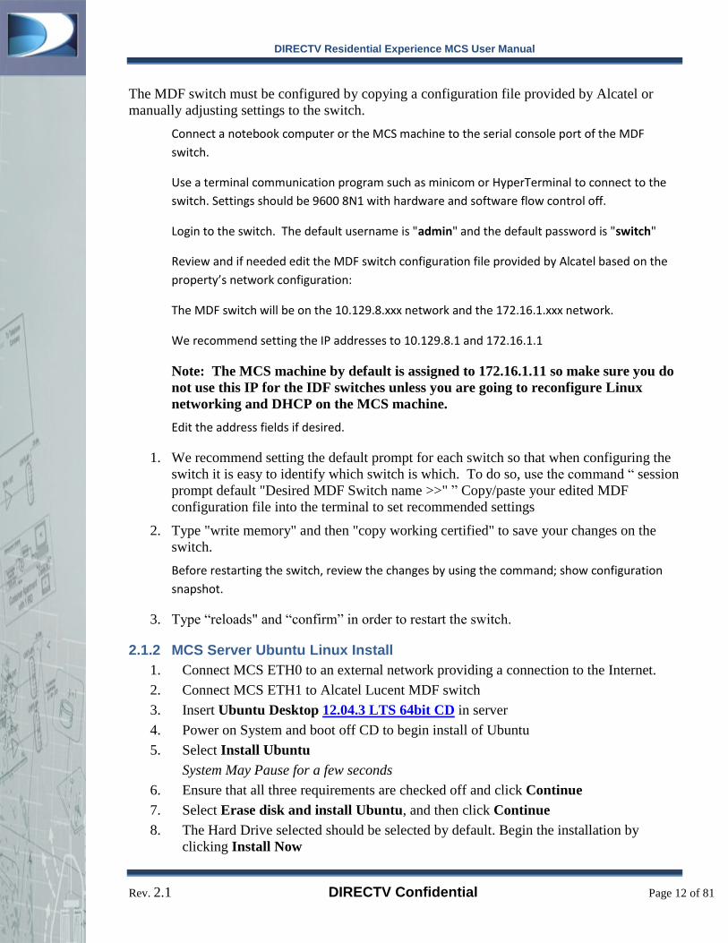
The MDF switch must be configured by copying a configuration file provided by Alcatel or
manually adjusting settings to the switch.
Connect a notebook computer or the MCS machine to the serial console port of the MDF
switch.
Use a terminal communication program such as minicom or HyperTerminal to connect to the
switch. Settings should be 9600 8N1 with hardware and software flow control off.
Login to the switch. The default username is "admin" and the default password is "switch"
Review and if needed edit the MDF switch configuration file provided by Alcatel based on the
property’s network configuration:
The MDF switch will be on the 10.129.8.xxx network and the 172.16.1.xxx network.
We recommend setting the IP addresses to 10.129.8.1 and 172.16.1.1
Note: The MCS machine by default is assigned to 172.16.1.11 so make sure you do
not use this IP for the IDF switches unless you are going to reconfigure Linux
networking and DHCP on the MCS machine.
Edit the address fields if desired.
1. We recommend setting the default prompt for each switch so that when configuring the
switch it is easy to identify which switch is which. To do so, use the command “ session
prompt default "Desired MDF Switch name >>" ” Copy/paste your edited MDF
configuration file into the terminal to set recommended settings
2. Type "write memory" and then "copy working certified" to save your changes on the
switch.
Before restarting the switch, review the changes by using the command; show configuration
snapshot.
3. Type “reloads" and “confirm” in order to restart the switch.
2.1.2 MCS Server Ubuntu Linux Install
1. Connect MCS ETH0 to an external network providing a connection to the Internet.
2. Connect MCS ETH1 to Alcatel Lucent MDF switch
3. Insert Ubuntu Desktop 12.04.3 LTS 64bit CD in server
4. Power on System and boot off CD to begin install of Ubuntu
5. Select Install Ubuntu
System May Pause for a few seconds
6. Ensure that all three requirements are checked off and click Continue
7. Select Erase disk and install Ubuntu, and then click Continue
8. The Hard Drive selected should be selected by default. Begin the installation by
clicking Install Now

DIRECTV Residential Experience MCS User Manual
Rev. 2.1 DIRECTV Confidential Page 13 of 81
9. As the installation begins, select the appropriate Time Zone for the Site location. Then
click Continue
10. Select English (US) for both keyboard settings and select Continue
11. Enter Full Name for Administrator account
12. Type in a computer’s name such as “dre-mcs-server”
13. Enter Username for the Administrator account
14. Enter Password for the Administrator account
15. Re-Enter password for to verify
Ensure that the username and password is kept safe and is difficult to guess.
Gaining access to the MCS machine means the ability to compromise all hotel
SBBs and the MCS system.
16. Do not check off box to Encrypting your home directory
17. Select Continue to finish the installation
System will now finish installation
18. When the installation is complete, click on Restart Now
19. When prompted, remove the Ubuntu Installation CD and press Enter to Reboot
System will now reboot
2.1.3 Installing the MCS Software
You must have all the switches configured, all static IP addresses set before installing MCS
software. By default MCS uses IP address 172.16.1.11 when MCS installs so please make sure
no devices are configured to use this IP and no automatic DHCP services are set to give out an
IP in this range.
1. Determine and label the Ethernet ports on the server machine for ease of installation at
the hotel.
a. If you are unsure which Ethernet port is which, unplug all Ethernet connections
to the MCS machine and then plug one of the connections into one of the
Ethernet ports at random.
b. From the MCS server command line execute “dmesg” and examine the last few
lines of output.
c. Look for the line of text that is similar to the following:
0000:04:00.0: eth1: Link is Up 1000 Mbps Full Duplex,
Flow Control: None
d. Look for the “eth1” string. Repeat with different Ethernet ports until you’ve
located eth1 and eth0.
e. Label eth0 and eth1 for ease of installation in the hotel.
2. Ensure that your eth0 port is connected to a network with an internet connection and the
eth1 port is connected to the MCS network. You must have a connection to the internet
for the initial MCS installation even if there will be no connection in the hotel.

DIRECTV Residential Experience MCS User Manual
Rev. 2.1 DIRECTV Confidential Page 14 of 81
i. Verify by PINGING google.com
ii. Type ping google.com
3. Ensure that your eth1 port is connected to the MCS network
i. Verify by PINGING MDF Switch
ii. Type ping 172.16.1.1
4. Download & Extract MCS_<date>.tar.gz installer from www.DRESupport.com or MCS
CD/DVD provided by SkyWeb.
5. Start MCS installation process by changing to the MCS software directory and type in ./install.sh
a. For Ubuntu 12.04, you will need an Internet connection connected to the eth0
Ethernet jack.
i. If you are connecting into a separate standard DHCP network, connect
eth0 to the network.
Then type in ./install.sh --network=dhcp
b. Be sure to remember to disconnect eth0 when this entire installation procedure is
complete and restart the server.
6. Follow the on screen instructions. Be sure to have ready:
a. A live Internet connection for MCS to download the required packages (apache,
php, mysql, etc.)
b. The MySQL root password which you will define during installation.
c. The root MySQL password is only required for staging and should not need to be
given out. Please make sure this password is hard to guess and keep it safe as
security on the MCs machine could be compromised with this information.
7. Now open a web browser and go to http://localhost/sbbmgr/
8. The default username (without admin access) is: user and password is tiburon
9. The administrative username (with full access) is: mcsadmin and password is dtvmcsgo
10. Make sure you change the passwords on these default accounts as soon as possible in the
administrative tab. Do not give out the administrative username and password except to
those who you completely trust to configure MCS. Hotel front desk staff should only
need user level access.
2.1.4 Verifying Complete MCS installation
1. Verify that you can log into the MCS web interface by opening a web browser and going
to http://172.16.1.11/. If you cannot try connecting to http://localhost/sbbmgr/ from the
MCS itself. If you cannot then re-install the MCS software or contact dresupport.com.
If you can connect to localhost but not 172.16.1.11 check your network configuration
you may have an IP address conflict. See “Debugging MCS” for more information.
2. Verify that you can log in as mcsadmin and user and any other accounts that you’ve
created. If you cannot, please reset the passwords using the “MCS Troubleshooting”
section.

DIRECTV Residential Experience MCS User Manual
Rev. 2.1 DIRECTV Confidential Page 15 of 81
3. DRE Receivers should automatically appear in the system within 20 minutes. Please
refer to the “Debugging MCS” section if they do not.
2.1.5 Setting up User Accounts
MCS administrators such as the default administrator account have access to affect all
operations of the receivers on the system as well as change system settings on the MCS Linux
server machine. Therefore, for security reasons you should never allow hotel front desk staff or
other end users to have access to the mcsadmin account or another account setup as an
administrator.
The default account “user” has been setup for your convenience however if all end users log in
using the “user” account, there will be no way to distinguish user activity in the logs and it will
make it more difficult to track down any MCS issues. It is highly recommended that you create
a user account for each end user who will use MCS such as hotel front desk staff.
2.1.5.1 Changing the Password of “mcsadmin” and “user”
To change the passwords on the “mcsadmin” and “user” account:
1. Log out of MCS if you are logged in by clicking the “Log out” link in the upper right
corner of the MCS interface.
2. Click “Click here to log in” if you were logged into MCS. Otherwise go to MCS via a
web browser: http://172.16.1.11/
3. Log into the account you wish to change the password for – “mcsadmin” or “user”
4. Select “Change Password” in the top right corner of the interface to the right of
“Administrator Settings”.
5. Type in your existing password in the “Old Password” box.
6. Type in the new password and confirmation in the next two boxes.
7. Click on the “Set New Password” button at the bottom of the pop-up box.
8. You should see “Successfully changed password.” appear at the top of the screen.
9. The password for the account you logged into is now changed to a new password.
10. Repeat steps 1-9) for both the mcsadmin and user accounts or any other accounts you
may have already created that you wish to change the password for.
2.1.5.2 Creating New Accounts for End Users
To create a new account with only user level access:
1. Log out of MCS if you are logged in by clicking the “Log out” link in the upper right
corner of the MCS interface.
2. Click “Click here to log in” if you were logged into MCS. Otherwise go to MCS via a
web browser: http://172.16.1.11/
3. Log into MCS as administrator -- mcsadmin
4. Select the “Administrator Settings” link from the upper right of the MCS interface.
DIRECTV Residential Experience MCS User Manual
Rev. 2.1 DIRECTV Confidential Page 16 of 81
5. Select the “User Management” tab which should be the second tab on the interface.
6. Click on the “Add New User” button in the bottom left hand side of the form.
7. Fill out the appropriate information for the user. This information is stored in MCS and
not used elsewhere but maybe used to send alerts to users.
8. Ensure that the “Normal” radio button is checked at the bottom of the form. This will
give the user regular access and prevent access to administrative areas of MCS.
9. Click the “Add User” button.
10. Confirm that you wish to add this user to the system.
11. The new user has now been added to the system with user level access. Please note that
the user will be prompted to change their password when they log into this account for
security reasons.
12. You can verify the new user by logging out and logging into this account.
13. Repeat steps 1-12) as needed to create a user account for all end users of the MCS
system.
2.1.6 Use MCS to set SBB Managed Mode
Note: Before performing this step ensure that all SBBs are connected to the MCS network.
Once you have MCS up and running, all property SBBs need to be configured to work with
MCS. If you need help with any of the below steps in detail see the appropriate section under
“Using MCS Web Interface”.
1. Make sure you’ve completed “Verifying Complete MCS installation” above. You must
wait for all SBBs to populate inside of the list and indicate status “alive” in order to
perform these steps. See “MCS Troubleshooting” if you are having trouble with this
step.
2. Log out of MCS if you are logged in by clicking the “Log out” link in the upper right
corner of the MCS interface.
3. Click “Click here to log in” if you were logged into MCS. Otherwise go to MCS via a
web browser: http://172.16.1.11/
4. Log into MCS as administrator – mcsadmin
5. Select the “Administrator Settings” link from the upper right of the MCS interface.
6. Select the “Administrative SBB List” tab which should be selected by default.
7. Click inside the checkboxes of the SBBs you wish to configure or click inside the “All”
checkbox to select all SBBs currently in the MCS system.
8. Select “Set Management Mode” from the “Commands” Drop down list.
9. Click the “Go” Button to the right of the “Commands” Drop down list.
10. Ensure that “Managed” is selected. If it is not, select it from the “Management Mode”
drop down menu.

DIRECTV Residential Experience MCS User Manual
Rev. 2.1 DIRECTV Confidential Page 17 of 81
14. Double check that the active status of all SBBs listed is “yes” under the “alive” column.
Any SBBs not listed as “alive” will not receive the managed mode setting and will need
to be set at a later date. For help in fixing SBBs that are not “alive”, see “Debugging
MCS”.
15. Scroll down to the end of the list and select the “Apply” button.
16. Wait for MCS to indicate success.
17. If you receive a “Failed to configure the selected receivers!” message then take note of
the RID of the SBB(s) that failed. See “Troubleshooting SBB receivers” for
information on how to fix an individual SBB.
18. Keep in mind that any SBBs that are not “alive” or that were listed in the failure
message have not been configured to managed mode and you should repeat steps 4-15
once the SBB issues have been resolved.
2.1.7 Setting Property Information on MCS
Be sure to set up the Property Information correctly and completely before shipping out any
MCS. This information is extremely important for support purposes, to help ensure all the
information needed to properly assess and troubleshoot problems that may arise. If this
information is not supplied, the process of troubleshooting problems may take longer.
Please refer to Section 5.3 for more details on Property Identification. Here is a short summary
of the steps to follow to enter in the Property Name.
1. Log into the MCS using the Administrator’s username and password
2. At the top menu of links, click the Administrator Settings link
3. Under the Property Name/Location, enter the Property Name
a. The Property Name should follow the format:
Property Name – City, State
As an example: Holiday Inn – El Segundo, CA
4. Be sure to enter the Property Address to be explicitly clear of the site.
2.1.8 Setting a Property Logo on SBBs
To configure all staged SBBs to display the correct hotel property logo, please follow the steps
listed below:
1. Make sure you’ve completed “Verifying Complete MCS installation” above. You must
wait for all SBBs to populate inside of the list and indicate status “alive” in order to
perform these steps. See “MCS Troubleshooting” if you are having trouble with this
step.
2. Log out of MCS if you are logged in by clicking the “Log out” link in the upper right
corner of the MCS interface.
DIRECTV Residential Experience MCS User Manual
Rev. 2.1 DIRECTV Confidential Page 18 of 81
3. Click “Click here to log in” if you were logged into MCS. Otherwise go to MCS via a
web browser: http://172.16.1.11/
4. Log into MCS as administrator -- mcsadmin
5. Select the “Administrator Settings” link from the upper right of the MCS interface.
6. Select the “Property Logo” tab which is the third tab/header.
7. Select “Upload New Logo”. A dialog box with two fields for inserting logos should
appear.
8. Click the ‘Browse’ button next to “Insert Logo”.
9. Navigate to the location of the hotel logo file you wish to use and double click on it or
click the filename and then click “Open”. Please keep in mind that the logo file must
be PNG file that must have a width of 125 pixels and a height of 65 pixels. All other
file types and sizes will result in an error message.
10. Once you’ve selected a PNG file click the “Set Logo” button. You should see a status
message at the top of the screen that indicates “New Logo Uploaded. Click 'Apply' to
Make Active.” If you encounter any errors ensure that you are using a PNG file with
width of 125 pixels and height of 65 pixels.
11. At this point the logo you selected should be pictured next to “Logo”. The Logo is now
saved in the MCS system but it is not yet applied to any receivers.
12. Click the “Apply Logos” button in order to send the logo to all SBBs connected to
MCS. You will receive a confirmation message – click “Apply”.
13. Wait for MCS to return a success message – “Logo has been applied to all property
SBBs.”
14. If you receive a “Failed to configure the selected receivers!” message then take note of
the RID of the SBB(s) that failed. See “Troubleshooting SBB receivers” for
information on how to fix an individual SBB.
15. Keep in mind that any SBBs that are not “alive” or that were listed in the failure
message have not been configured to managed mode and you should repeat steps 4-15
once the SBB issues have been resolved.
2.1.9 Configuring Hotel Channel Lists on SBBs
MCS provides the ability to configure many different channel line ups for each receiver or sets
of receivers on the hotel property. It is important that you set these up for hotel staff to ensure a
smooth MCS experience. By default there maybe channels you do not wish hotel guests to see
so make sure you review the complete channel list and configure a default hotel channel list.
1. Make sure you’ve completed “Verifying Complete MCS installation” above. You must
wait for all SBBs to populate inside of the list and indicate status “alive” in order to
perform these steps. See “MCS Troubleshooting” if you are having trouble with this
step.
2. Go to MCS via a web browser: http://172.16.1.11/
3. Log into MCS

DIRECTV Residential Experience MCS User Manual
Rev. 2.1 DIRECTV Confidential Page 19 of 81
4. Click on configure channel lists button which is represented by two square overlapping
boxes to the right of the “Channels List” label.
5. The “Configure Channel Lists” window will load and should display a complete
channel list with checkboxes next to each channel. By default all checkboxes are
unchecked.
6. Select the channels you would like to configure for a hotel channel list by clicking on
the checkbox of each channel. To select a range of channels click in a checkbox on the
first channel of the range and then shift-click on the last channel’s checkbox in the
range. You should see each checkbox in the range appear selected with a checkmark.
7. Once you have selected all the channels you would like to configure click on the “Save
as New List” button at the top of the “Configure Channel Lists” window.
8. You will then be prompted for a channel list name. Type in a channel list name and
then click “Confirm”. The new channel list is now saved.
9. You can verify the channel list you created by clicking the drop down list next to
“Saved lists:” and selecting the name of the channel you just created. You should see
the checkboxes for the channels you selected populate in the channel list as you make
the selection.
10. Repeat steps 7-10 to create as many channel lists as you’d like. To start over with a
blank channel list, select “none” from the “Saved Lists” drop down list.
11. When you are finished click “done” on the main “Configure Channel Lists” window.
12. Select all SBBs by clicking the checkbox next to “All” on the receiver list.
Alternatively if you want certain groups or SBBs to have different channel lists, select
only the SBBs you wish to set.
13. Select the channel list you created from the drop down list under “Channels List”.
14. Select “Assign”
15. Double check that the active status of all SBBs listed is “yes” under the “alive” column.
Any SBBs not listed as “alive” will not receive the favorite list setting and will need to
be set at a later date. For help in fixing SBBs that are not “alive”, see “Debugging
MCS”.
16. Scroll down to the end of the list and select the “Apply” button.
17. Wait for MCS to indicate success.
18. If you receive a “Failed to configure the selected receivers!” message then take note of
the RID of the SBB(s) that failed. See “Troubleshooting SBB receivers” for
information on how to fix an individual SBB.
19. Keep in mind that any SBBs that are not “alive” or that were listed in the failure
message have not been configured to use the channel list you created and you should
repeat steps 13-20 once the SBB issues have been resolved.
20. Your receivers are now configured to use the channel list you created. You can repeat
steps 13-20 as needed to configure multiple sets of receivers with different default
settings.

DIRECTV Residential Experience MCS User Manual
Rev. 2.1 DIRECTV Confidential Page 20 of 81
2.1.10 Configuring Hotel Defaults on SBBs
A default setting is a list of configuration options that a receiver will return to when reset either
by issuing a “Reset Defaults” command or when a guest checks in or out causing PMS to issue
a “Reset Defaults” command. The default configuration can set the channel back to a pre-
defined hotel welcome channel, reset parental controls, and change back any subtitles and
language settings. To create a default setting:
1. Make sure you’ve completed “Verifying Complete MCS installation” above. You must
wait for all SBBs to populate inside of the list and indicate status “alive” in order to
perform these steps. See “MCS Troubleshooting” if you are having trouble with this
step.
2. Go to MCS via a web browser: http://172.16.1.11/
3. Log into MCS
4. Click on defaults button which is represented by two square overlapping boxes to the
right of the “Defaults” label.
5. The “Configure Defaults” window will open and show a series of default options.
6. Set the default channel to the channel you wish the receiver to return to when it is reset.
7. Set the default favorite list. This is either all the channels the hotel system will receive
or the currently customized channel list for that individual receiver.
a. Choosing the currently customized channel list means that the SBB will have its
channel list reset to the favorite list last sent with a Channel List “assign” command.
See the section on Assigning a Favorite List for more details.
b. Choosing “Currently Customized Favorites” is recommended to avoid confusion
when end users try to change the favorite list of a set of receivers. If you choose
“Channels I Get” the last favorite list sent to the receiver will be cleared and the
channel list on the receiver will be set to the entire channel list that the hotel
receives are authorized for.
8. Select a default bar color for menu and info screens on the receiver.
9. Select default screen resolutions, aspect ratios and formats to match the specific TV
models installed in the hotel.
10. Select a default closed captioning and audio language.
11. Select whether Dolby Digital should be enabled and whether the receiver should run in
native mode.
12. Choose closed captioning options. “Not Enabled” turns captioning off, “Subtitles” or
“Closed Captioning” turn on options for the SBB.
13. Click “Save as New Setting”.
14. You will then be prompted for a setting name. Type in a name and then click
“Confirm”. The new channel list is now saved.

DIRECTV Residential Experience MCS User Manual
Rev. 2.1 DIRECTV Confidential Page 21 of 81
15. You can verify the configuration settings list you created by clicking the drop down list
next to “Saved lists:” and selecting the name of the settings you just created. You
should see the options you selected return to the appropriate positions.
16. Repeat steps 7-10 to create as many settings lists as you’d like. To start over with a
blank channel list, select “none” from the “Saved Lists” drop down list.
17. When you are finished click “done” on the main “Configure Defaults” window.
18. Select all SBBs by clicking the checkbox next to “All” on the receiver list.
Alternatively if you want certain groups or SBBs to have different default settings,
select only the SBBs you wish to set.
19. Select the default settings list you created from the drop down list under “Defaults”.
20. Select “Assign”
21. Double check that the active status of all SBBs listed is “yes” under the “alive” column.
Any SBBs not listed as “alive” will not receive the defaults settings and will need to be
set at a later date. For help in fixing SBBs that are not “alive”, see “Debugging MCS”.
22. Scroll down to the end of the list and select the “Apply” button.
23. Wait for MCS to indicate success.
24. If you receive a “Failed to configure the selected receivers!” message then take note of
the RID of the SBB(s) that failed. See “Troubleshooting SBB receivers” for
information on how to fix an individual SBB.
25. Keep in mind that any SBBs that are not “alive” or that were listed in the failure
message have not been configured to the default settings and you should repeat steps
13-20 once the SBB issues have been resolved.
26. Your receivers are now configured to use default settings you created. You can repeat
steps 19-26 as needed to configure multiple sets of receivers with different default
settings.
2.1.11 Preparing Installation Spreadsheet
To greatly simplify and streamline the hotel installation process you can input room, receiver
and PMS information while installing SBBs in each hotel room.
To facilitate this process, MCS provides a CSV template for inputting information that can later
be imported into MCS. We highly recommend this step. To download the CSV template:
1. Click “Click here to log in” if you were logged into MCS. Otherwise go to MCS via a
web browser: http://172.16.1.11/
2. Log into MCS as administrator -- mcsadmin
3. Select the “Administrator Settings” link from the upper right of the MCS interface.
4. Click on the “Import & Export” tab which is the last tab on the right.
5. At the bottom of the page is a web link labeled “Save Template File.” Click this link to
open or save the CSV file.

DIRECTV Residential Experience MCS User Manual
Rev. 2.1 DIRECTV Confidential Page 22 of 81
6. Copy this CSV file onto a computer/device that installers will use when installing SBBs
in each hotel room.
2.2 Property Onsite Installation
After DRE system is successfully staged and setup in a lab environment, it can be moved onsite
to the property.
2.2.1 MCS Server and Network installation
Ensure that your MCS system has been installed correctly in staging before taking these steps at
the hotel. You will find it far easier to debug any issues that arise in a staging environment
rather than onsite at the property.
1. Hook up the MCS server machine in a secure location where it can be connected to the
MDF switch. Remember the MCS server machine must be connected on the eth1
interface to the MDF switch. Power on the MCS machine.
2. Install the IDF switches throughout the hotel such that each SBB can be connected to an
IDF switch. Remember to wire each IDF switch to the MDF switch through the ports
you configured in the Alcatel switch configuration section of the staging installation.
2.2.2 SBB Room Installation
Install the SBBs in each room. During the installation make sure you make note of the Room
number, CAM, RID and PMS identifier for each room to input into the CSV spreadsheet.
Doing so will allow you to import this information into MCS at the end of the installation. The
following staging is highly recommended and can be done offsite or onsite:
1. Label the SBB with Room Number
2. If a hotel room has multiple receivers you can name the receiver with its room number
and location. For example “Room 426-Bedroom” or “Room 426-LivingRoom”. You
should choose unique names for every receiver in the hotel to avoid any later confusion
on sending MCS commands to the incorrect receiver
3. The PMS identifier for the room should be entered for each room if known. This will
allow the MCS property management integration system to automatically return the
receivers in a room to their default settings on a guest check-in or check-out.
4. You can specify any group name you wish for each receiver. It is recommended that
you group receivers in a way that is easy and convenient for hotel staff to manage them.
For example “Floor 4” or “Wing 6”. The group for any receiver can always be adjusted
from the MCS system at a later time.

DIRECTV Residential Experience MCS User Manual
Rev. 2.1 DIRECTV Confidential Page 23 of 81
3 In-Room Verification Before performing the In-Room Verification, ensure that the Receiver Configuration for each
receiver in the entire site is correct using the MCS. For DRE Loop Through sites with the
DSWM13, be sure to check that all receivers have unique SWM channel assignments. Ensure
all system verification procedures have been verified first.
Following steps are the “in room” verification procedure to ensure the SBB (DIRECTV
Receiver) is functioning correctly. If there are any unanticipated differences you should not
install the SBB in the room
1. Turn on TV\DIRECTV Receiver
2. Press Menu
3. Verify the DRE Menu is present with Parental Controls
4. Press Exit
5. Press Guide
6. Verify Property Logo is Displayed in the guide
7. Verify Channel Lineup matches the channel list set from MCS
8. Change the channel to a different channel than the default channel.
9. Power Off TV\DIRECTV Receiver
10. Power On TV\DIRECTV Receiver
11. Verify Channel has reverted back to default channel
3.1 Import Receiver information into MCS
Import receiver information from the CSV spreadsheet. Return to the MCS machine and
copy the CSV file you created from your mobile device to the MCS server machine. Then
follow these steps to import the list:
Go to MCS via a web browser: http://172.16.1.11/
Log into MCS as administrator -- mcsadmin
Select the “Administrator Settings” link from the upper right of the MCS interface.
Click on the “Import & Export” tab which is the last tab on the right.
Click on “Import Spreadsheet” button.
Click on the “Browse” button and select the location of the CSV file you copied over to the MCS
machine.
Double click the file or select the file and click “Open”
Click the “Import” button.

DIRECTV Residential Experience MCS User Manual
Rev. 2.1 DIRECTV Confidential Page 24 of 81
MCS will now import all receiver information you put into the CSV file into the receiver list.
Any receivers with the same RID as receivers already in the list will be overwritten with the new
information you’ve supplied. Otherwise new entries are created under the group headings you
specified in the CSV file.
Verify the receivers show up in the main list by clicking “View Receiver Management List” in the
upper right hand corner to return to the main receiver list screen and expand all receivers by
clicking the + icon next to “All”.
If MCS has been running for 20 minutes or longer all receivers in the list should be listed as
“Yes” under the “Active” column. If any are not, ensure that you have entered the correct RID
and CAM for the receivers tagged with “No” in the “Active” column and if necessary follow the
steps in the “Troubleshooting MCS” section.

DIRECTV Residential Experience MCS User Manual
Rev. 2.1 DIRECTV Confidential Page 25 of 81
4 MCS Web User Interface The DIRECTV Residential Experience Management Control System or DRE-MCS provides the
ability to manage the DIRECTV Set Back Boxes (SBBs) installed at a particular property. The
DRE-MCS includes the ability to send commands to any combination of SBBs (such as reboot
or display a message on the TV screen), Property Management System Integration (PMS) –
such as the ability to automatically reset a SBB to its defaults on a check-in or check-out, and
the ability to view and configure SBB status and settings.
4.1 Login
Access the MCS Web User Interface via a web browser at http://172.16.1.11/sbbmgr
Enter your user name and password in the appropriate fields and click “Submit”.
The default user and administrator accounts should not be used by end users of the system. In
addition during staging and installation the passwords for the default accounts should have been
changed. Ensure that you receive your account name and password from your system
administrator.
4.2 Receiver Management List
If you log in to an administrator account you’ll see a screen with “Administrator” settings on the
top. Otherwise the administrator and user accounts will look similar.

DIRECTV Residential Experience MCS User Manual
Rev. 2.1 DIRECTV Confidential Page 26 of 81
User account screenshot:
Administrator account screenshot:
The first screen you’ll see in the MCS screen is the receiver list and main command screen
shown above. The main MCS screen has dropdowns for sending commands to receivers,
grouping receivers, assigning defaults and channel lists. In addition, MCS has several links at
the top right corner of the page for administrator settings (if logged into administrator),
changing your password, viewing the user logs and to log out of the system.
DIRECTV Residential Experience MCS User Manual
Rev. 2.1 DIRECTV Confidential Page 27 of 81
The MCS software version number will display on this screen in the lower right hand corner
under the receiver list.
4.2.1 Navigating the MCS receiver list
The first entry in the receiver list is always the “All” marker. “All” has a checkbox beside it that
when checked will automatically check all receivers connected to the MCS system (whether
they are active or not).
Each group’s checkbox works similarly. When you click on a checkbox next to a group name, all
receivers inside of the group are checked or unchecked correspondingly.
Clicking the + and – boxes will collapse and expand the view of all receivers, or a group of
receivers depending on which box you click.
Each receiver information line has a checkbox to its left. To check or uncheck an individual
receiver, use these checkboxes. When you issue MCS commands the commands will affect all
of the receivers that are currently check marked. After a command is completed, all
checkmarks are removed and you must check off receivers or groups of receivers again to send
the next command.
4.2.2 Updates to the Receiver List
The MCS receiver list will automatically refresh every 10 minutes with the latest receiver
status. You can force MCS to retrieve the latest status from the database by clicking the reload
button on your web browser to cause the interface to refresh. Please note that this refresh does
not retrieve the latest status from the individual receivers only their latest reported status from
the database.
Each SBB sends update notifications to the MCS system on average every 11.25 minutes but
the time varies by 3.75 minutes in either direction. Hence you may have to wait for 15 minutes
to receive a status update from any individual SBB once its status is changed. Since the MCS
interface refreshes every 10 minutes it’s possible the current status may not be reflected on the
interface until the 2nd
refresh or 20 minutes after a change.
If you are not seeing receivers update in the list, see the “Debugging MCS” section to identify
and correct the problem.

DIRECTV Residential Experience MCS User Manual
Rev. 2.1 DIRECTV Confidential Page 28 of 81
4.2.3 Receiver information
On each receiver line the Room, RID, IP Address, Software Version, Signal Strength, STB
Model, Management Mode, Default Settings Status, Battery Status, and Active status are
displayed.
At the bottom corner of the receiver list, a small Gear button exists to configure and re-order
the columns in the receiver list. This menu will show even more columns that are not displayed
by default. When the set of columns are changed, they will remain configured that way until
cookies are reset by the browser.
4.2.3.1 Room
The room name is editable by any user and can be imported during MCS installation from the
receiver spreadsheet. Typically this will be the room number such as “Room 246” but it can be
any value you desire.
4.2.3.2 RID and CAM
The RID and CAM are the receiver identification number (on the receiver box itself) and the
card authorization number on the access card inserted in the receiver. The RID will never
change unless the receiver box is replaced. It is possible to replace the CAM. CAM
information is automatically updated and tied to the RID.
4.2.3.3 IP Address
The IP address field is the IP address reported by the receiver. This is automatically updated
whenever a receiver obtains a new IP address which may happen on a receiver reboot, a power
outage, or after a length of time. The IP Address is provided by the DHCP server running on the
MCS.
4.2.3.4 Software Version
This is the software version running on the DIRECTV receiver unit. The version is
automatically updated when the receiver obtains a new software version. The software on each
receiver is automatically updated from time to time over the satellite connection typically in the
overnight hours.
4.2.3.5 Signal Strength
The signal strength field is updated to indicate the latest satellite signal strength to the receiver.
This number is a snapshot taken at the last receiver update and may not be indicative of the
current satellite signal at any given moment (see the “updates to receiver list” section for more
details on refresh rates)
4.2.3.6 Hardware Model
The model of the STB will be displayed in the list to identify if the receiver is a standard
receiver or DVR.
4.2.3.7 Managed Mode Status
This interactive column will poll all the STBs to determine their Management Mode setting.
DIRECTV Residential Experience MCS User Manual
Rev. 2.1 DIRECTV Confidential Page 29 of 81
Please use this to ensure that the entire site is set in Managed mode.
4.2.3.8 Default Settings Status
This interactive column will poll all the STBs to determine if they have a default settings
configuration applied. Please use this to ensure that the entire site is configured with default
settings.
4.2.3.9 Active Status
The active status is a simple yes/no that indicates whether or not the receiver is currently
available on the MCS system. A value of “no” indicates that the receiver has been
disconnected, has encountered an error state or may have an installation or connection problem
with the MCS system. See “Debugging MCS” and the sections specific to receivers for
assistance in locating and fixing a receiver problem.
A receiver will switch to active status “no” after MCS does not receive any messages from it for
30 minutes. Because of the interface refresh time (10 minutes) it’s possible that you may not
see a receiver switch status until close to 40 minutes after the problem occurs.
You can hover the mouse curser over a “no” status to view the last time a particular receiver
reported its status to the MCS.
4.2.3.10 Battery Status
The list will show the current battery status of the remote control in the room. If low, the icon
should turn red and show only 1 bar left on the icon. The remotes batteries should be replaced
soon.
4.2.3.11 Switch Type
This column will show what kind of switch the Receiver is configured for. The current options
are SWM and DSWM13. This helps identify the satellite signal distribution setup for the site.
4.2.3.12 SWM Channels
This column will show what channels the Receiver is configured for. This will help ensure
proper SWM channel assignment when using the DSWM13.
4.2.3.13 SWM Serial Number
This column will show the serial number of the SWM module that the Receiver is connected to.
Use this in conjunction with the SWM Channels column to ensure that the system is correctly
configured. This column may also be useful in troubleshooting the system; if problematic
receivers all belong to the same SWM, it will be easier to directly identify and locate the
module for troubleshooting purposes.
4.2.4 Expanded Receiver Information
You may now click on the [+/-] icon next to a specific receiver to check its current
configuration. When you expand a specific receiver, MCS will load that receiver’s settings by
communicating with it at that moment to retrieve its most up to date status.

DIRECTV Residential Experience MCS User Manual
Rev. 2.1 DIRECTV Confidential Page 30 of 81
You can see what the default settings are as well as if the receiver is in Managed mode. If the
receiver is not active, the information will not load.
4.3 Configuring and Assigning Channel List
4.3.1 Configuring Channel List:
MCS allows the property’s management to setup a channel list for the receivers. Channel lists
control what channels show up in the guide display on a particular receiver. Please keep in
mind that even if the channel does not display in the guide it can still be tuned manually via the
remote control by entering the channel number. Channel lists are not channel locking
mechanism, merely a display convenience.
To open the channel configuration interface, click the overlapping squares icon to the right of
the “Channel Lists” label. You may experience a short delay before the interface window
displays or a short delay before the channel list populates. MCS retrieves the channel list from
the receivers connected to MCS in real-time which causes a few seconds delay.
If you do not see a channel list display and instead receive a channel list error you may not have
any receivers connected to MCS that are active to retrieve the channel list from. First make sure
you have at least one receiver active in the Management List. If you continued getting channel
list error follow the steps in “Debugging MCS”.
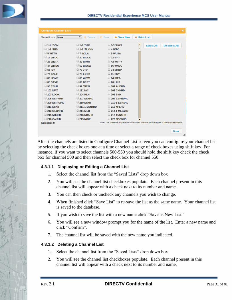
Following is a snapshot of channel list configuration interface:
DIRECTV Residential Experience MCS User Manual
Rev. 2.1 DIRECTV Confidential Page 31 of 81
After the channels are listed in Configure Channel List screen you can configure your channel list
by selecting the check boxes one at a time or select a range of check boxes using shift key. For
instance, if you want to select channels 500-550 you should hold the shift key check the check
box for channel 500 and then select the check box for channel 550.
4.3.1.1 Displaying or Editing a Channel List
1. Select the channel list from the “Saved Lists” drop down box
2. You will see the channel list checkboxes populate. Each channel present in this
channel list will appear with a check next to its number and name.
3. You can then check or uncheck any channels you wish to change.
4. When finished click “Save List” to re-save the list as the same name. Your channel list
is saved to the database.
5. If you wish to save the list with a new name click “Save as New List”
6. You will see a new window prompt you for the name of the list. Enter a new name and
click “Confirm”.
7. The channel list will be saved with the new name you indicated.
4.3.1.2 Deleting a Channel List
1. Select the channel list from the “Saved Lists” drop down box
2. You will see the channel list checkboxes populate. Each channel present in this
channel list will appear with a check next to its number and name.

DIRECTV Residential Experience MCS User Manual
Rev. 2.1 DIRECTV Confidential Page 32 of 81
Click the “Delete List” button. The channel list is immediately deleted from the database and
removed from the drop menu.
4.3.2 Assigning Channel List:
To configure a receiver or set of receivers with a pre-defined channel list:
1. Select one or more receivers by clicking their checkboxes. You can also select an
entire group if desired or click the checkbox next to “All” to select all receivers.
2. Click the “Channel List” drop down box and select the channel list you wish to send to
the receivers.
3. Click the “Assign” Button next to the drop down box.
4. You must confirm the command by reviewing the receiver list and clicking “Confirm”.
5. You will see a “Configuring selected receivers. Please wait….” message while MCS
sends the appropriate commands to the receivers.
6. After a short period of time you will see “Successfully configured selected receivers”.
This indicates that the selected receivers have appropriately received the command.
7. If you receive a message indicating that certain receivers did not receive the message,
make note of the RIDs. You can try sending the command again or if you continue to
experience problems see “Debugging MCS”.
4.4 Configuring and Assigning Defaults
4.4.1 Configuring Default Settings
MCS UI allows the property’s management to configure default settings for DIRECTV
revivers. To open the Configure Default interface, click the overlapping squares icon to the right
of the “Defaults” label. Through the Configure Default screen you can set the desired Default
Channel, Default Channel List, Default Bar Color, Default Resolution, Default Screen Format,
Default Display Language, Default Audio Language and Dolby digital , native mode, closed
captioning settings.

DIRECTV Residential Experience MCS User Manual
Rev. 2.1 DIRECTV Confidential Page 33 of 81
Following shows a screen capture of the Configure Default Screen:
After setting the desired default settings you can save it as a new setting. Also, saved lists can
be displayed, edited and deleted through the Saved Lists drop down menu on the Configure
Defaults screen.
*NOTE: If Default Channel/Favorites List is set to “Current Customized Favorites” please
make sure you have configured and assigned the Channel List
4.4.2 Assigning Default Settings
To assign a receiver or set of receivers with pre-defined default settings:
1. Select one or more receivers by clicking their checkboxes. You can also select an
entire group if desired or click the checkbox next to “All” to select all receivers.
2. Click the “Defaults” drop down box and select the default setting you wish to send to
the receivers.
3. Click the “Assign” Button next to the drop down box.
4. You must confirm the command by reviewing the receiver list and clicking “Confirm”.
5. You will see a “Configuring selected receivers. Please wait….” message while MCS
sends the appropriate commands to the receivers.
6. After a short period of time you will see “Successfully configured selected receivers”.
This indicates that the selected receivers have appropriately received the command.
7. If you receive a message indicating that certain receivers did not receive the message,
make note of the RIDs. You can try sending the command again or if you continue to
experience problems see “Debugging MCS”.

DIRECTV Residential Experience MCS User Manual
Rev. 2.1 DIRECTV Confidential Page 34 of 81
4.5 Sending MCS Commands
MCS UI provides the following commands:
1. Reboot
2. Reset Defaults
3. Send Message
4. Set Room Number
5. Check-in
6. Check-out
Reboot MCS has the ability to soft reboot a receiver or set of receivers:
1. Select one or more receivers by clicking their checkboxes. You can also select an
entire group if desired or click the checkbox next to “All” to select all receivers.
2. Select “Reboot” from the “Commands” drop down box and then click “Go”.
3. You will receive a confirmation dialog listing each of the receivers the command will
be sent to. Click “Confirm” after you have reviewed your selections.
DIRECTV Residential Experience MCS User Manual
Rev. 2.1 DIRECTV Confidential Page 35 of 81
4. You will see a “Configuring selected receivers. Please wait….” message while MCS
sends the appropriate commands to the receivers.
5. After a short period of time you will see “Successfully configured selected receivers”.
This indicates that the selected receivers have appropriately received the command.
6. If you receive a message indicating that certain receivers did not receive the message,
make note of the RIDs. You can try sending the command again or if you continue to
experience problems see “Debugging MCS”.
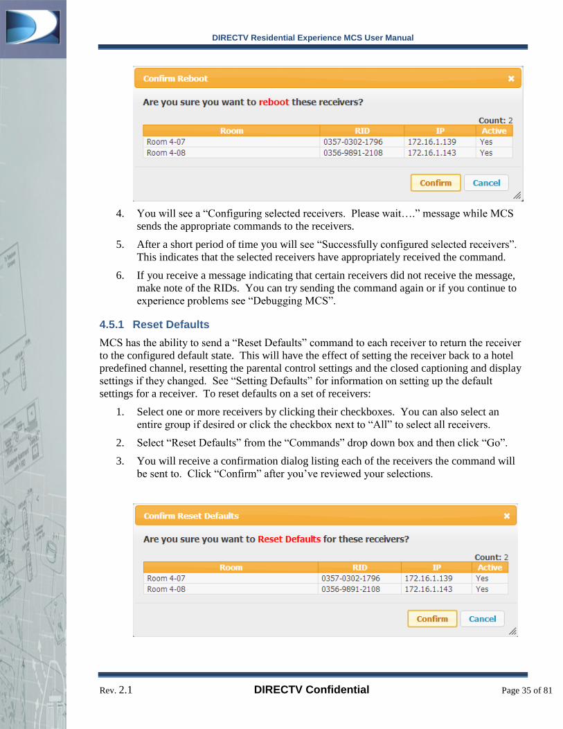
4.5.1 Reset Defaults
MCS has the ability to send a “Reset Defaults” command to each receiver to return the receiver
to the configured default state. This will have the effect of setting the receiver back to a hotel
predefined channel, resetting the parental control settings and the closed captioning and display
settings if they changed. See “Setting Defaults” for information on setting up the default
settings for a receiver. To reset defaults on a set of receivers:
1. Select one or more receivers by clicking their checkboxes. You can also select an
entire group if desired or click the checkbox next to “All” to select all receivers.
2. Select “Reset Defaults” from the “Commands” drop down box and then click “Go”.
3. You will receive a confirmation dialog listing each of the receivers the command will
be sent to. Click “Confirm” after you’ve reviewed your selections.

DIRECTV Residential Experience MCS User Manual
Rev. 2.1 DIRECTV Confidential Page 36 of 81
4. You will see a “Configuring selected receivers. Please wait….” message while MCS
sends the appropriate commands to the receivers.
5. After a short period of time you will see “Successfully configured selected receivers”.
This indicates that the selected receivers have appropriately received the command.
6. If you receive a message indicating that certain receivers did not receive the message,
make note of the RIDs. You can try sending the command again or if you continue to
experience problems see “Debugging MCS”.
Send Message MCS can send a popup display message on a TV screen by sending a message to
one or more receivers. Hotel front desk staff may use this to send an import alert to all guests or
to confirm a change in service. To send a message to a particular hotel room:
1. Select one or more receivers by clicking their checkboxes. You can also select an
entire group if desired or click the checkbox next to “All” to select all receivers.
2. Select “Send Message” from the “Commands” drop down box and then click “Go”.
3. A window will appear prompting you for the title of the message and the body of the
message.
4. Enter a title for your message. The title is the window title of the on-screen message.
5. Enter a body for your message. The body of the message is the text displayed under the
title on the screen.
6. Select a time for the message to remain on the screen. The default is approximately 10
seconds. You may also select between 1 minute, 5 minutes, 10 minutes or 30 minutes.
7. Click “Send Message” to confirm that you want to send the message to the displayed
receivers.
8. You will see a “Configuring selected receivers. Please wait….” message while MCS
sends the appropriate commands to the receivers.

DIRECTV Residential Experience MCS User Manual
Rev. 2.1 DIRECTV Confidential Page 37 of 81
9. After a short period of time you will see “Successfully configured selected receivers”.
This indicates that the selected receivers have appropriately received the command.
10. If you receive a message indicating that certain receivers did not receive the message,
make note of the RIDs. You can try sending the command again or if you continue to
experience problems see “Debugging MCS”.
4.5.2 Set Room Name/Number
When a new receiver appears in the “Unassigned” list or when you want to change the name of
a receiver’s room:
1. Select one or more receivers by clicking their checkboxes. You can also select an
entire group if desired or click the checkbox next to “All” to select all receivers.
2. Select “Set Room Number” from the “Commands” drop down box and then click “Go”.
3. A set room number interface will display prompting you to enter the room number or
name of all of the receivers you selected. There are no restrictions on what you can use
as a room name/number.
4. When finished select “Set Room Number” and the receiver list will update with the
new room name/numbers that you entered.
Note: Set Room Number command allows the user to set the room numbers associated with the
receivers. This room number is unique to the web system and separate from the PMS identifier.
4.5.3 Check-in
Check-in command can be issued from the Check-In button or from the Commands drop down
menu. By default the check-in command is simply a “Reset Defaults” command sent to each
receiver to return the receiver to the configured default state. This will have the effect of setting
the receiver back to a default channel, resetting the parental control settings, closed captioning
and display settings if they changed.
However, for the DVR platform, Check-In will clear out the recorded content from the DVR to
ensure an empty playlist for the incoming guest.
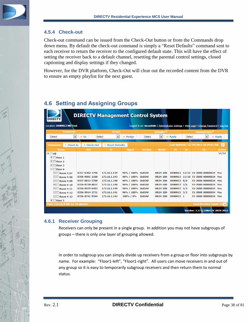
DIRECTV Residential Experience MCS User Manual
Rev. 2.1 DIRECTV Confidential Page 38 of 81
4.5.4 Check-out
Check-out command can be issued from the Check-Out button or from the Commands drop
down menu. By default the check-out command is simply a “Reset Defaults” command sent to
each receiver to return the receiver to the configured default state. This will have the effect of
setting the receiver back to a default channel, resetting the parental control settings, closed
captioning and display settings if they changed.
However, for the DVR platform, Check-Out will clear out the recorded content from the DVR
to ensure an empty playlist for the next guest.
4.6 Setting and Assigning Groups
4.6.1 Receiver Grouping
Receivers can only be present in a single group. In addition you may not have subgroups of
groups – there is only one layer of grouping allowed.
In order to subgroup you can simply divide up receivers from a group or floor into subgroups by
name. For example: “Floor1-left”, “Floor1-right”. All users can move receivers in and out of
any group so it is easy to temporarily subgroup receivers and then return them to normal
status.

DIRECTV Residential Experience MCS User Manual
Rev. 2.1 DIRECTV Confidential Page 39 of 81
4.6.2 The Unassigned Group
All receivers that are newly discovered or imported without a group will display in the
“Unassigned” group. You can move receivers out of the unassigned group into any group of by
using the “Groups” drop down menu.
4.6.3 Creating a New group
1. Groups must have at least one receiver. Empty groups are automatically deleted.
2. Select one or more receivers by clicking their checkboxes
3. Select “Add New Group” from the “Groups” drop down box on the main interface.
4. Click “Assign”. A window will display prompting you for the name of the new group.
5. Type a new group name and click “Add Group”
6. The interface will return to the receiver list. The new group will appear sorted in the
list. To expand the group and review the receivers click the “+” icon.
4.6.4 Moving Receivers In-Between Groups
1. Groups must have at least one receiver. Empty groups are automatically deleted.
2. Select one or more receivers by clicking their checkboxes. You can also select an
entire group if desired.
3. Click on the “Groups” drop down box and select the group you wish to move the
receivers into. To create a new group see “Creating a New Group” above.
4. Click “Assign”.
5. You must confirm the move by clicking “Confirm”.
6. The selected receivers will be moved into the new group.
4.6.5 Removing a Group
Groups are removed automatically when a group is empty. To remove a group, simply follow
the “Moving Receivers” instructions above to move all receivers out of a group and it will be
automatically removed.

DIRECTV Residential Experience MCS User Manual
Rev. 2.1 DIRECTV Confidential Page 40 of 81
4.7 View Logs
MCS UI allows the user to review the commands recently sent to DIRECTV Receivers.
Following is a screen shot of the log:

DIRECTV Residential Experience MCS User Manual
Rev. 2.1 DIRECTV Confidential Page 41 of 81
5 Administrator Settings
5.1 Administrative SBB List
5.1.1 Set Management Mode
The Set Management Mode command sets the SBB in managed mode or unmanaged mode – a
dialog box pops up to ask the user which mode to set. Managed Mode
RC50/RC70H Power Button – Resets to Default Channel
Parental Control Option showing on Info Banner Menu
Unmanaged Mode
RC50/RC70H Power Button – Resets Receiver to Default Parental Control Option does not show
on Info Banner Menu
**Note: All DRE boxes should be set to be in Managed mode. Operating a DRE system in
unmanaged mode requires prior approval from the Commercial Business Group and/or your
DIRECTV Area Sales Manager (ASM)
5.1.2 Set PMS ID
Set PMS ID command takes a 6 byte field parameter which is associated to the properties’ PMS
system’s PMS ID (room number) list. The PMS ID can be the same or different from the web
interface room number. If there are more than one receiver in a room and the PMS system only
has one PMS ID in its list the PMS ID should be the same for all the boxes in that room. Please
note that before setting the PMS ID, receiver should be assigned to a room number for better
organization of the SBB list.
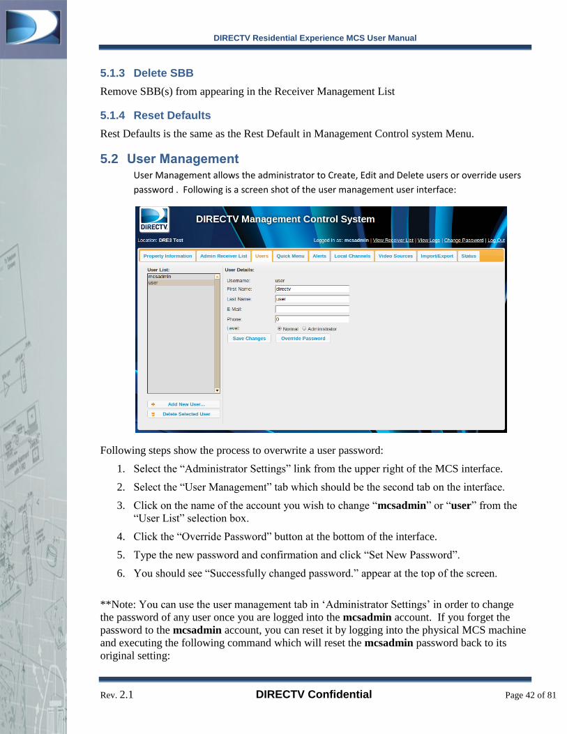
DIRECTV Residential Experience MCS User Manual
Rev. 2.1 DIRECTV Confidential Page 42 of 81
5.1.3 Delete SBB
Remove SBB(s) from appearing in the Receiver Management List
5.1.4 Reset Defaults
Rest Defaults is the same as the Rest Default in Management Control system Menu.
5.2 User Management User Management allows the administrator to Create, Edit and Delete users or override users
password . Following is a screen shot of the user management user interface:
Following steps show the process to overwrite a user password:
1. Select the “Administrator Settings” link from the upper right of the MCS interface.
2. Select the “User Management” tab which should be the second tab on the interface.
3. Click on the name of the account you wish to change “mcsadmin” or “user” from the
“User List” selection box.
4. Click the “Override Password” button at the bottom of the interface.
5. Type the new password and confirmation and click “Set New Password”.
6. You should see “Successfully changed password.” appear at the top of the screen.
**Note: You can use the user management tab in ‘Administrator Settings’ in order to change
the password of any user once you are logged into the mcsadmin account. If you forget the
password to the mcsadmin account, you can reset it by logging into the physical MCS machine
and executing the following command which will reset the mcsadmin password back to its
original setting:

DIRECTV Residential Experience MCS User Manual
Rev. 2.1 DIRECTV Confidential Page 43 of 81
sudo /opt/dre/bin/resetMCSAdmin.sh
5.3 Property Information
5.3.1 Property Location
The Administrator may specify the Property Name/Location as well as the Property Address.
Please be sure to specify this information accurately in order to identify the site from the Alert
e-mails.
5.3.1.1 Format
To help identify the Property, especially identifying MCS Alert Notification emails, please use
the name of the Property along with the City and State.
For example:
Supreme Hotels – Townfield, MD
Hilton Garden Inn LAX – El Segundo, CA
Please try to be specific, as there may be more than one “Days Inn” within a particular city. Add
information which can be used to uniquely identify that site, (i.e. LAX). You may wish to
consult the Property Staff for that site’s unique name.
5.3.1.2 During Installation
The Property Name must be entered during the installation of the MCS software.
When running the installer, you will be prompted for the Property name:
Please enter the name of the Property: Supreme Hotels –
Townfield, MD
Installing for Supreme Hotels – Townfield, MD
This step is required in order to properly identify this MCS as the server for a given site.
5.3.2 Property Logo
MCS Administrator settings UI allows the administrator to set the property logo for the
receivers that are on the DRE network. Standard definition logos must be exactly 125x65 pixels
and in PNG format.
Uploading and applying a logo are separate functions. When a logo is uploaded it is simply
stored on the MCS but is not sent out to the SBBs to set the logo. Clicking Apply Logo applies
the logo to all active SBBs on the property. Logos can only be set for ALL DRE receivers on
the system. Following is a snap shot of the Property Logo UI:

DIRECTV Residential Experience MCS User Manual
Rev. 2.1 DIRECTV Confidential Page 44 of 81
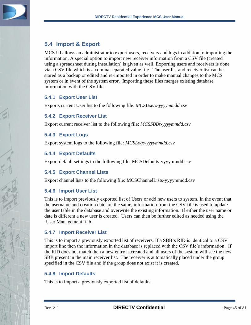
DIRECTV Residential Experience MCS User Manual
Rev. 2.1 DIRECTV Confidential Page 45 of 81
5.4 Import & Export
MCS UI allows an administrator to export users, receivers and logs in addition to importing the
information. A special option to import new receiver information from a CSV file (created
using a spreadsheet during installation) is given as well. Exporting users and receivers is done
via a CSV file which is a comma separated value file. The user list and receiver list can be
stored as a backup or edited and re-imported in order to make manual changes to the MCS
system or in event of the system error. Importing these files merges existing database
information with the CSV file.
5.4.1 Export User List
Exports current User list to the following file: MCSUsers-yyyymmdd.csv
5.4.2 Export Receiver List
Export current receiver list to the following file: MCSSBBs-yyyymmdd.csv
5.4.3 Export Logs
Export system logs to the following file: MCSLogs-yyyymmdd.csv
5.4.4 Export Defaults
Export default settings to the following file: MCSDefaults-yyyymmdd.csv
5.4.5 Export Channel Lists
Export channel lists to the following file: MCSChannelLists-yyyymmdd.csv
5.4.6 Import User List
This is to import previously exported list of Users or add new users to system. In the event that
the username and creation date are the same, information from the CSV file is used to update
the user table in the database and overwrite the existing information. If either the user name or
date is different a new user is created. Users can then be further edited as needed using the
‘User Management’ tab.
5.4.7 Import Receiver List
This is to import a previously exported list of receivers. If a SBB’s RID is identical to a CSV
import line then the information in the database is replaced with the CSV file’s information. If
the RID does not match then a new entry is created and all users of the system will see the new
SBB present in the main receiver list. The receiver is automatically placed under the group
specified in the CSV file and if the group does not exist it is created.
5.4.8 Import Defaults
This is to import a previously exported list of defaults.

DIRECTV Residential Experience MCS User Manual
Rev. 2.1 DIRECTV Confidential Page 46 of 81
5.4.9 Import Channel Lists
This is to import a previously exported file of Channel Lists. When importing a channel list file,
the name(s) of the channel list must not already exist, otherwise the import will fail.
5.4.10 Import New Receiver Installation CSV
Be sure to download the template file and fill out the fields as shown in the header. Each line is a separate receiver and each field must be filled in with commas separating each field.
5.5 Local Channels
MCS enables the property manager to create a local customized channel to be available for the
SBBs on the property to view. To create a local channel, the administrator must provide a video
file or network camera and specify it when configuring a video source. Once the video source is
configured, the administrator must create a channel which will enable the SBBs to tune to that
video.
5.5.1 Local Channel Content Format Guidelines
In order for A/V content to be streamed out by the MCS and played back by the SBB, the
content must be properly formatted. The content must be encapsulated with correctly formed
whole MPEG-2 transport (ts) packets as defined by ISO/IEC standard 13818-1 (aka ITU-T Rec.
H.222.0). Within the ts packets, there can be one video stream and several audio streams. The
transport packets do not require any Program Specific Information (PSI), as the video PID and
audio PIDs are specified when importing the content by creating a Video Source. The PCR for
the transport stream must be associated with the video PID and be spaced no more than 35ms
apart.
The video stream must be H.264 encoded as defined by ISO/IEC 14496-10 (aka. MPEG-4 Part
10). The video resolution and frame-rate must remain constant throughout the content, and
should use well-known industry accepted resolutions and frame-rate for TV: 640x480, 704x480,
720x480, 704x480, 720x480, 1,280×720 and 1920x1080 for resolution and frame-rate of
23.976, 24, 25, 29.97, 30, 50, 59.94 and 60. Content with higher than 1920x1080 resolution or
frame-rates higher than 60 are not acceptable for use in the LCI system. HD (720+) content is
highly recommended for use in LCI to maximize the delivered video quality to the hotel
patrons. In order to prevent content from overflowing the delivery network and cause visual
artifacts, encoded bitrate should average less than 8Mbps per channel.
For the audio stream, the encoding must be AC-3 as defined in ATSC A52. The audio stream
must use industry standard sampling rate of 48 kHz, with 16 bits per sample. The AC-3
encoding of up to 5.1 channels is supported and audio bitrate of up to 384kbps is supported.
The content should be designed to be looped. There should be black screen lead-in of at least
one second and lead-out of at least one second to make the loop seamless.

DIRECTV Residential Experience MCS User Manual
Rev. 2.1 DIRECTV Confidential Page 47 of 81
5.5.2 Create Video Source
Select the “Video Sources” tab to view the current video sources.
Click on [+New Video Source] to create a new video source.
5.5.2.1 Add Video Source from File
The video file must be copied to the MCS Server. A tree of folders will be presented from
which you can select the video file. When the video file is selected, give the video source an
appropriate name. This name will be used when configuring a channel in the next section.
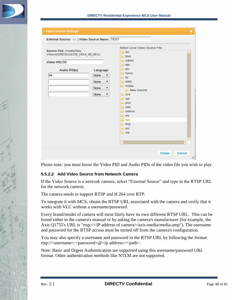
DIRECTV Residential Experience MCS User Manual
Rev. 2.1 DIRECTV Confidential Page 48 of 81
Please note: you must know the Video PID and Audio PIDs of the video file you wish to play.
5.5.2.2 Add Video Source from Network Camera
If the Video Source is a network camera, select “External Source” and type in the RTSP URL
for the network camera.
The camera needs to support RTSP and H.264 over RTP.
To integrate it with MCS, obtain the RTSP URL associated with the camera and verify that it
works with VLC without a username/password.
Every brand/model of camera will most likely have its own different RTSP URL. This can be
found either in the camera's manual or by asking the camera's manufacturer (for example, the
Axis Q1755's URL is "rtsp://<IP address of camera>/axis-media/media.amp"). The username
and password for the RTSP access must be turned off from the camera's configuration.
You may also specify a username and password in the RTSP URL by following the format:
rtsp://<username>:<password>@<ip address>/<path>.
Note: Basic and Digest Authentication are supported using this username/password URL
format. Other authentication methods like NTLM are not supported.

DIRECTV Residential Experience MCS User Manual
Rev. 2.1 DIRECTV Confidential Page 49 of 81
Enter an appropriate name for this video source. This name will be used when configuring a
channel in the next section.
5.5.3 Create Local Channel
Now that a video source is created, you must assign that video content to be broadcast on a
specific channel.
Click the [+ New Channel] button to create a new channel and fill in the fields in the dialog.

DIRECTV Residential Experience MCS User Manual
Rev. 2.1 DIRECTV Confidential Page 50 of 81
When all the fields are filled out, you may choose the Video Source you previously created as
the content for playback on this channel. You may also specify a Parental Rating for the Video
content so that Parental Controls may restrict it.
Please consider what content is appropriate or inappropriate for broadcast before using
this feature.
5.5.4 Set Channel Numbers
Once the channel has been created, you must choose the channel number. The channel numbers
follow a “major-minor” numbering scheme. Once you’ve selected the channel number, select
[Set Channel Numbers] to save your changes.
Now that the changes are saved, click [Refresh Channel Guide] to update the SBBs on the
network to these new channels.
Note: Changing a channel definition may invalidate the entry in channel lists that contain the
LCI channel.
5.6 E-mail Alerts
MCS supports sending e-mail alerts to the administrators and users when certain events occur on the
system. MCS currently supports monitoring:
% of Inactive Receivers in the network
Signal Strength too low
Daily Report
PMS Failure Alert

DIRECTV Residential Experience MCS User Manual
Rev. 2.1 DIRECTV Confidential Page 51 of 81
To configure the E-mail alerts, please enter in an e-mail address for the intended recipients in
the User Management screen as shown in Section 5.2. Once the users’ email addresses have
been saved, you may create an alert by clicking on [+ Add Alert].
Alerts require an SMTP Server to be specified. Please refer to Section 0 for information on
setting up the SMTP Server information.
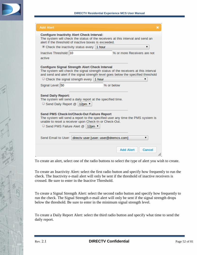
DIRECTV Residential Experience MCS User Manual
Rev. 2.1 DIRECTV Confidential Page 52 of 81
To create an alert, select one of the radio buttons to select the type of alert you wish to create.
To create an Inactivity Alert: select the first radio button and specify how frequently to run the
check. The Inactivity e-mail alert will only be sent if the threshold of inactive receivers is
crossed. Be sure to enter in the Inactive Threshold.
To create a Signal Strength Alert: select the second radio button and specify how frequently to
run the check. The Signal Strength e-mail alert will only be sent if the signal strength drops
below the threshold. Be sure to enter in the minimum signal strength level.
To create a Daily Report Alert: select the third radio button and specify what time to send the
daily report.
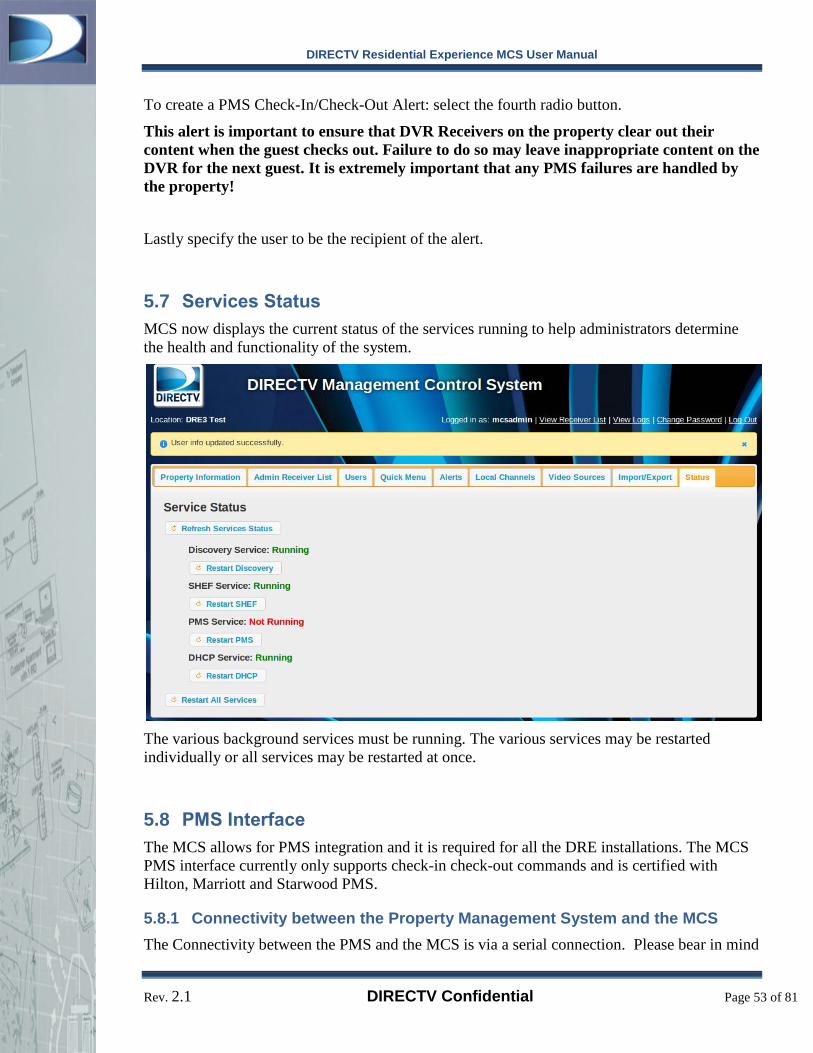
DIRECTV Residential Experience MCS User Manual
Rev. 2.1 DIRECTV Confidential Page 53 of 81
To create a PMS Check-In/Check-Out Alert: select the fourth radio button.
This alert is important to ensure that DVR Receivers on the property clear out their
content when the guest checks out. Failure to do so may leave inappropriate content on the
DVR for the next guest. It is extremely important that any PMS failures are handled by
the property!
Lastly specify the user to be the recipient of the alert.
5.7 Services Status
MCS now displays the current status of the services running to help administrators determine
the health and functionality of the system.
The various background services must be running. The various services may be restarted
individually or all services may be restarted at once.
5.8 PMS Interface
The MCS allows for PMS integration and it is required for all the DRE installations. The MCS
PMS interface currently only supports check-in check-out commands and is certified with
Hilton, Marriott and Starwood PMS.
5.8.1 Connectivity between the Property Management System and the MCS
The Connectivity between the PMS and the MCS is via a serial connection. Please bear in mind

DIRECTV Residential Experience MCS User Manual
Rev. 2.1 DIRECTV Confidential Page 54 of 81
when performing a site survey to determine how the PMS connection will be made if the MCS
is not in close proximity to the property’s PMS.
The PMS interface requires the following connectors:
1 Female DB-25 to RJ45 converter (Connects to PMS Server)
1 Female DB-9 to RJ45 converter (Connects to MCS)
RJ-45 DB-25 Signal DB-25 Color
1 8 DCD Blue
2 4 RTS Orange
3 6 DSR Black
4 2 TxD Red
5 3 RxD Green
6 7 GND Yellow
7 5 CTS Brown
8 20 DTR White
Table 2: Pin numbers for DB-25 and RJ45. (Note: only pins 2, 3, and 7 are need)
RJ-45 To DB-9 Signal DB-9 Color
1 4 DTR Blue
2 8 CTS Orange
3 4 DTR Black
4 2 TxD Red

DIRECTV Residential Experience MCS User Manual
Rev. 2.1 DIRECTV Confidential Page 55 of 81
5 3 RxD Green
6 5 GND Yellow
7 7 RTS Brown
8 1 &6
DCD
DSR White
Table 3: Pin numbers for DB-9 and RJ45. (Note: only pins 2, 3, and 5 are need)
**Note: MCS only requires the 3 highlighted signal/pin#, if connecting the rest of the
signals both ends of the cable need to be connected.
**Note: The PMS interface requires a dedicated PMS port and it might incur additional
costs for the property. MCS Serial Port Settings for PMS Interface
5.8.2 PMS Serial Port Configuration
In order to configure PMS interface on the MCS server you can access the setup section of
MCS. In the PMS tab, you can view the current PMS configuration and update it needed. You
can also restart or check the status of the PMS Interface from Administrator’s section Status tab.
5.9 Parental Control Configuration
Basic DRE provides limited Parental Control. Parental Control functionality is not controlled
via a centralized server and can only be enabled and disabled on each receiver using the
receiver’s user interface. Therefore, it is recommended that you track the receivers that have
been put in Parental Control mode and disable Parental Control after guest check-out to make
sure that there are no Parental Control limitations when there is a new guest check-in.
Power Cycling the DRE Receiver does not disable/reset Parental Control. It can only be
disabled via Keyword Search or MCS.
Enabling the Parental Control feature on DRE Receivers via Keyword Search
1. Press the Menu key on the remote control for the receiver you wish to enable with the
parental control.
2. Navigate to the “Search” option. Choose the “Keywords” option.
3. Using the remote control keypad or the letters on the Keyword Search screen type:
DREPARENTALCONTROLON
4. Press Exit key on remote control to get to Live Video. Press the Info key on the remote
control. The words “Parental Control” should appear on the receiver’s Info Banner at the top of
the screen.
5. You can navigate to parental control menu and configure your desired settings.

DIRECTV Residential Experience MCS User Manual
Rev. 2.1 DIRECTV Confidential Page 56 of 81
Disabling the Parental Control feature on DRE Receivers via Keyword Search
1. Press the Menu key on the remote control for the receiver you wish to enable with the
parental control.
2. Navigate to the “Search” option. Choose the “Search” option.
3. Using the remote control keypad or the letters on the Keyword Search screen type:
DREPARENTALCONTROLOFF
4. Press Exit key on remote control to get to Live Video. Press the Info key on the remote
control. The words “Parental Control” should NOT appear on the receiver’s Info Banner at the
top of the screen. Also, parental control password and settings should reset to default settings.

DIRECTV Residential Experience MCS User Manual
Rev. 2.1 DIRECTV Confidential Page 57 of 81
6 Setup Section In order to access the Setup section, manually change the URL in the browser to
http://172.16.1.11/sbbmgr/setup
6.1 Dealer Information
Be sure to enter proper contact information identifying the Dealer or Distributor who is
supporting this site. This information will be shown in the Property Information section in the
Administrator’s section of MCS. This section can contain HTML tags to help format the Dealer
or Distributor information when displayed in the Administrator’s section.
Optionally, for reference purposes please enter the account number for the property. Certain
sites may use multiple accounts, if this is the case, please enter at least one of them if available.
If all the accounts are known, please enter them all separated by commas.

DIRECTV Residential Experience MCS User Manual
Rev. 2.1 DIRECTV Confidential Page 58 of 81
6.2 Network
The Network section shows the current networking configuration of the MCS. It also provides
the ability to trigger the MCS to ping www.dresupport.com. If MCS successfully is able to ping
dresupport.com, then it is a good sign that the networking of MCS is setup correctly.
Remote Access should also be enabled to ensure MCS is accessible remotely by dresupport.com
support teams.
SMTP Server
The MCS requires an SMTP server to be configured to send out Alert emails. Please consult
your SMTP service provider for this configuration information. The fields required include:
SMTP Server: This field is the hostname of the SMTP server. If the SMTP requires SSL or TLS,
please edit the URL to specify the protocol. Ex. ssl://smtp.gmail.com/ or
tls://smtp.example.com/

DIRECTV Residential Experience MCS User Manual
Rev. 2.1 DIRECTV Confidential Page 59 of 81
SMTP Port: Depending on the protocol and the use of encryption, this field can vary. For
normal SMTP connections, the port number is 25. For SSL/TLS connections, the port may be
465 or may vary.
SMTP Username: The SMTP username, normally the email address of the sender
SMTP Password: The SMTP password.
6.3 PMS
This section enables the installer to configure the PMS settings without manually changing the
configuration file. You may select from available serial ports as well as configure the baud rate
and the PMS type.

DIRECTV Residential Experience MCS User Manual
Rev. 2.1 DIRECTV Confidential Page 60 of 81
6.4 Verification
This section enables the installer to create a Diagnostic and Reporting Tool Report to send to
dresupport.com. Be sure to enter how many network switches are used in the DRE system. If
the MCS is able to successfully ping dresupport.com, then clicking Send DART Report should
succeed in uploading the DART report to dresupport.com directly. If you are having network
configuration trouble, you may download the DART report and save it to a USB stick to email
to dresupport.com manually.

DIRECTV Residential Experience MCS User Manual
Rev. 2.1 DIRECTV Confidential Page 61 of 81
6.5 System Update
This section will enable MCS to update its version by downloading a new software release on
its own. You will need your dresupport.com login information in order to trigger a new software
update. As an installer, when starting the update, it is recommended that you view the update
log and refresh the update log to ensure that the download was initiated and is proceeding. If
there was an error starting the download, then there is likely a network issue preventing MCS
from reaching dresupport.com. The webpage must be reloaded in order to attempt an update
again.
6.6 Reboot
You can now reboot the MCS from the setup section.
Please be sure to wait and check that the MCS has rebooted successfully.

DIRECTV Residential Experience MCS User Manual
Rev. 2.1 DIRECTV Confidential Page 62 of 81
7 Troubleshooting DRE Problems
7.1 MCS Receiver List Updating
The main list of SBBs is updated automatically. A problem here can be indicative of many
issues. Read through and follow these instructions to determine and fix an MCS problem.
7.1.1 The MCS screen does not appear to be refreshing
The main receiver list in MCS automatically refreshes the status of all receivers connected to
the system. It is possible that after the interface has been left open and inactive for a day or
more that the screen may no longer refresh. To fix this problem, simply reload the webpage by
clicking the reload button on your web browser. You may have to log into MCS after the page
reload.
Once your system is fully operational it is perfectly normal for the MCS receiver screen to look
the same after a refresh if all SBBs on the property are listed as ‘alive’. You may not notice any
changes in the status list. This is perfectly normal. If you are concerned that the refresh is not
operational, simply re-load the webpage.
If you have waited sufficiently long and refreshed the page and MCS is still not updating,
follow the steps in the “Debugging MCS” section below.
7.1.2 I just added/fixed/changed a receiver and it is not showing in the list
The automatic refresh that occurs is every 10 minutes in the latest MCS release. You must
wait for 10 minutes for the screen to update. You can force MCS to retrieve the latest status
from the database by clicking the reload button on your web browser to cause the interface to
refresh. Please note that this refresh does not retrieve the latest status from the individual
receivers only their latest reported status from the database.
Each SBB sends update notifications to the MCS system on average every 11.25 minutes but
the time varies by 3.75 minutes in either direction. Hence you may have to wait for 15 minutes
to receive a status update from any individual SBB once its status has changed. The MCS
interface refreshes every 10 minutes. Hence it’s possible the current status may not be reflected
on the interface until the 2nd
refresh or 20 minutes after a SBB status change.
If you’ve waited sufficiently long and MCS is still not updating, follow the steps in the
“Debugging MCS” section below.
7.1.3 A receiver is offline but still showing “alive” in the MCS receiver list
SBBs in the MCS system are not listed as status “no” under the alive column until after they
have not sent messages to the MCS server for 30 minutes. Hence it is not possible to know the
exact moment a receiver becomes inactive. If a receiver is rebooted or experiences a temporary
outage you may not see a status update on the MCS interface. However, any receiver offline for
30 minutes or longer will update its status to “no”
If you have waited sufficiently long and MCS is still not updating, it’s possible that the receiver
has encountered a bad state. Follow the steps in “Debugging SBB issues” first and if that does
not fix the problem follow the steps in “Debugging MCS” below.
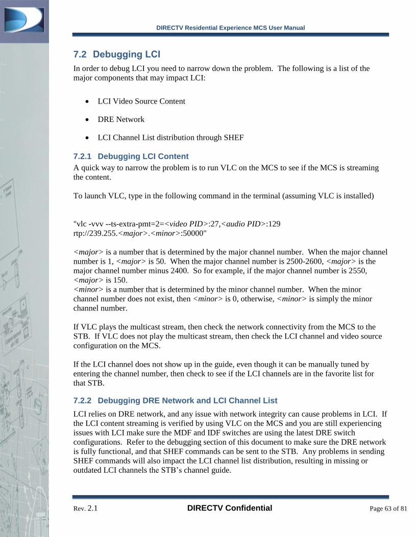
DIRECTV Residential Experience MCS User Manual
Rev. 2.1 DIRECTV Confidential Page 63 of 81
7.2 Debugging LCI
In order to debug LCI you need to narrow down the problem. The following is a list of the
major components that may impact LCI:
LCI Video Source Content
DRE Network
LCI Channel List distribution through SHEF
7.2.1 Debugging LCI Content
A quick way to narrow the problem is to run VLC on the MCS to see if the MCS is streaming
the content.
To launch VLC, type in the following command in the terminal (assuming VLC is installed)
"vlc -vvv --ts-extra-pmt=2=<video PID>:27,<audio PID>:129
rtp://239.255.<major>.<minor>:50000"
<major> is a number that is determined by the major channel number. When the major channel
number is 1, <major> is 50. When the major channel number is 2500-2600, <major> is the
major channel number minus 2400. So for example, if the major channel number is 2550,
<major> is 150.
<minor> is a number that is determined by the minor channel number. When the minor
channel number does not exist, then <minor> is 0, otherwise, <minor> is simply the minor
channel number.
If VLC plays the multicast stream, then check the network connectivity from the MCS to the
STB. If VLC does not play the multicast stream, then check the LCI channel and video source
configuration on the MCS.
If the LCI channel does not show up in the guide, even though it can be manually tuned by
entering the channel number, then check to see if the LCI channels are in the favorite list for
that STB.
7.2.2 Debugging DRE Network and LCI Channel List
LCI relies on DRE network, and any issue with network integrity can cause problems in LCI. If
the LCI content streaming is verified by using VLC on the MCS and you are still experiencing
issues with LCI make sure the MDF and IDF switches are using the latest DRE switch
configurations. Refer to the debugging section of this document to make sure the DRE network
is fully functional, and that SHEF commands can be sent to the STB. Any problems in sending
SHEF commands will also impact the LCI channel list distribution, resulting in missing or
outdated LCI channels the STB’s channel guide.

DIRECTV Residential Experience MCS User Manual
Rev. 2.1 DIRECTV Confidential Page 64 of 81
7.3 Debugging SBB Issues
Ensure that you have checked the above section on receiver list updating first to make sure there
is actually a problem behind the scenes before going further in this section. The first step in
ensuring MCS is functioning correctly is to ensure all SBBs are functioning correctly.
7.3.1 Verify SBBs are set for Hospitality
The MCS hospitality menu screen should only show three or four options – “Guide”, “Search
for Shows”, “Help” and possibly “Parental Controls”. If this is not the case, your SBBs may not
be using the appropriate software version. Reissue a software upgrade to all SBBs that maybe
affected. The DRE SW version will start with 0x85**. Each new DRE software release will
increment above 0x8500.
If receivers are not using the correct hospitality software they may not send updates to the MCS
system and MCS will be unable to report their status or send commands to them.
You may also expand a specific receiver in MCS, and MCS will query the STB for its settings.
In the data that is displayed, you can see if the SBB is in Managed or Unmanaged mode.
7.3.2 Verify SBBs are activated
Tune the receiver to a few different channels the hotel should receive such as CNN, ESPN, etc.
If you receive activation error message such as “721 Channel Not Authorized” on currently
tuned channel, the SBB may not have been activated correctly. Re-activate the box via Agent
Services.
7.3.3 Verify SBBs are active and displaying video
Check the SBB display for any On-Screen error messages.
In the event that the SBB software has encountered a software bug and is frozen or stuck on an
error screen, red button reset the SBB box. It is possible for an SBB to be in a state where it
will appear active in the MCS even though it is not functional to the user. This requires a visual
check of on-screen errors. A detailed description of the error message and/or state of the DRE
receiver must be logged and submitted to your distributors for problem tracking.
7.3.4 Verify the SBB connection to the IDF switch
Verify all connections from the SBB to the IDF switch. Check the network wiring diagrams
and ensure that the green lights are lit on the DECA in the IDF closet which services the SBB
box and at the Ethernet connection to the IDF switch. The DECA link lights that should be
Green are: c.Link, NTWK, and Power. Ensure that the DECAs are connected to the configured
IDF Ethernet ports and not the GigE uplink port on the IDF switch.
7.3.5 Verify MCS Configuration
Once all SBB issues have been corrected and verified and you have read through the
verification steps in “MCS Receiver List Updating” and the problem still exists, consult the
“Debugging MCS” section.
DIRECTV Residential Experience MCS User Manual
Rev. 2.1 DIRECTV Confidential Page 65 of 81
7.4 Debugging
Ensure that you have followed the verification steps for MCS Receiver List Updating. If the
problem lies with an individual SBB, ensure that you have followed the verification and
corrective steps in “Debugging SBB issues” before visiting this section.
If MCS is still not functioning correctly, use the following verification and correction
procedures to locate the MCS problem:
7.4.1 Verifying MCS Server Network Configuration
Proper network IP address assignment is important for MCS functionality. In order to execute
the following commands you will need to be logged into the MCS machine with an account that
has sudo access to run processes as root. If you do not have this access, please contact your
MCS administrator for assistance. Verify that all IP addresses are unique and set correctly by:
1. Execute the following from the MCS server command line:
ifconfig
2. Check the output from the above command. Check that each device is listed and has an
IP address assigned which will appear next to “inet addr:”. The devices and IP
addresses should correspond to the following list adjusting for any changes your
network administrator may have made:
a) eth0 – Should not have inet addr field specified.
b) eth1 – Should not have inet addr field specified.
c) lo -- 127.0.0.1
d) vlan1001 – 10.129.8.11
e) vlan2000 – 172.16.1.11
3. Ensure that the last two lines in the file match regardless of whether or not the interfaces
are correct from the ‘ifconfig’ command.
4. Restart the network to make all changes effective by typing:
sudo /etc/init.d/networking force-reload
5. Reload the MCS processes by typing:
sudo /etc/init.d/sbbutils restart
7.4.2 Verifying the Switch Configuration
Ensure that the settings on your MDF and IDF switches are correct.
7.4.2.1 Verify Port Configuration on (MDF) ALU6400
From the MCS machine command prompt you should be able to connect to the MDF switch via
one of its two IP addresses: 10.129.8.1 and 172.16.1.1. If these addresses are different from
your installation setup please substitute the correct IP address for the default ones below:
1. From the MCS command line execute:

DIRECTV Residential Experience MCS User Manual
Rev. 2.1 DIRECTV Confidential Page 66 of 81
ping 10.129.8.1
2. You should see the following type of output:
PING 10.129.8.1 (10.129.8.1) 56(84) bytes of data.
64 bytes from 10.129.8.1: icmp_seq=1 ttl=64 time=1.11 ms
64 bytes from 10.129.8.1: icmp_seq=2 ttl=64 time=1.09 ms
64 bytes from 10.129.8.1: icmp_seq=3 ttl=64 time=1.15 ms
64 bytes from 10.129.8.1: icmp_seq=4 ttl=64 time=1.11 ms
3. If the output stalls after the first line or returns an error and you have already verified the
MCS Server Network configuration then your switch configuration is likely not correct
or you are experiencing a connection or hardware failure issue. Repeat the installation
steps for the MDF switch in the “Alcatel Switch Configuration” section of “Staging
Installation”.
4. Once you have verified connectivity to the MDF switch with the above ping command,
connect to the MDF switch by executing the following from the MCS command line:
5. You will be prompted for the MDF switch password. Enter the switch password you
setup in “Alcatel Switch Configuration”.
6. The switch configuration prompt should appear that will resemble:
DTV MDF Version 2.0>>
7. Type “show configuration snapshot” at the prompt and press enter.
8. Verify that the configuration shown matches the MDF switch setup from the MCS
installation directory or your configuration based on this sample file (ALU-6400.cfg.txt)
9. Press and hold the Control key while pressing the letter ‘D’ to exit the switch command
prompt.
7.4.2.2 Verify Port Configuration on IDF switches
From the MCS machine command prompt you should be able to connect to each IDF switch via
IP addresses: 10.129.8.x. Please note that IDF switch doesn’t have VLAN2000 IP address any
more and the only way to access the IDF switches on DRE network is through the Management
IP range. The IDF switches are typically configured to use IP addresses .2 through .20
excluding .1 which is reserved for the MDF switch and .11 which is reserved the MCS server
machine. Consult your local IP addressing scheme if these addresses have changed and
substitute the below IPs for the correct IP in your addressing scheme. Perform these steps one
for each IDF substituting the last .x for the correct IP number of that IDF (For example:
10.129.8.2, 10.129.8.3 etc.
1. From the MCS command line execute:
ping 10.129.8.x
2. You should see the following type of output:
PING 10.129.8.2 (10.129.8.2) 56(84) bytes of data.

DIRECTV Residential Experience MCS User Manual
Rev. 2.1 DIRECTV Confidential Page 67 of 81
64 bytes from 10.129.8.2: icmp_seq=1 ttl=64 time=1.11 ms
64 bytes from 10.129.8.2: icmp_seq=2 ttl=64 time=1.09 ms
64 bytes from 10.129.8.2: icmp_seq=3 ttl=64 time=1.15 ms
64 bytes from 10.129.8.2: icmp_seq=4 ttl=64 time=1.11 ms
3. If the output stalls after the first line or returns an error and you have already verified the
MCS Server Network configuration then your switch configuration is likely not correct
or you are experiencing a connection or hardware failure issue. Repeat the installation
steps for the MDF switch in the “Alcatel Switch Configuration” section of “Staging
Installation”.
4. Once you have verified connectivity to the IDF switch with the above ping command,
connect to the IDF switch by executing the following from the MCS command line:
5. You will be prompted for the IDF switch password. Enter the switch password you
setup in “Alcatel Switch Configuration”.
6. Ensure that the software version number listed during the login is the correct version. If
the version number does not match, contact the site dealer or Alcatel for instructions on
how to update the switch firmware version. The output should match:
Software Version 6.6.1.815.R01 Service Release, February 15,
2011.
7. The switch configuration prompt should appear that will resemble:
DTV IDF1 Version 2.0>
8. Type “show configuration snapshot” at the prompt and press enter.
9. Verify that the configuration shown matches the IDF switch setup from the MCS
installation directory or your configuration based on the latest DRE configuration file.
Please note that you can always get the latest DRE Switch configuration from DRE
Support Website.
10. Press and hold the Control key while pressing the letter ‘D’ to exit the switch command
prompt.
7.4.3 Verifying MCS DHCP Server Configuration
The DHCP server, usually running on the MCS server, handles all requests for IP address
assignments and tracks IP addresses for the entire network. In order to execute the following
commands you will need to be logged into the MCS machine with an account that has sudo
access to run processes as root. If you do not have this access, please contact your MCS
administrator for assistance.
To verify that DHCP is operating correctly:
1. Check the DHCP configuration file by typing at the command line prompt:
sudo cat /etc/dhcp3/dhcpd.conf
2. The last few lines of the file should read:
subnet 172.16.0.0 netmask 255.255.0.0 {

DIRECTV Residential Experience MCS User Manual
Rev. 2.1 DIRECTV Confidential Page 68 of 81
range 172.16.1.100 172.16.255.254;
}
3. If the IP addresses are incorrect, use your favorite text editor such as ‘pico’ or ‘vi’ to edit
the range to match the above.
4. Check the DHCP defaults file by typing at the command line prompt:
sudo cat /etc/default/dhcp3-server
5. The last line of the file should read:
INTERFACES="vlan2000"
6. If the interfaces line does not match, use your favorite text editor such as ‘pico’ or ‘vi’ to
edit the interface to match the above.
7. Check that DHCP has started by going to the MCS server machine and typing at a
command line prompt:
ps aux | grep dhcp
8. You should see the following process listed among the output:
/usr/sbin/dhcpd3 -q -pf /var/run/dhcp3-server/dhcpd.pid -cf
/etc/dhcp3/dhcpd.conf vlan2000
9. If the above line is not present, or if you have made changes to the dhcp.conf file or the
defaults/dhcp3-server file you should force a restart of DHCP by typing:
sudo /etc/init.d/dhcp3-server force-reload
10. After DHCP reloading is complete you must also restart networking by typing:
sudo /etc/init.d/networking restart
11. Lastly, after networking reloads you must restart the MCS processes by typing:
sudo /etc/init.d/sbbutils restart
7.4.4 Verifying MCS Services
MCS’s utilities run in two separate modes – regular mode and debug mode. By default MCS
starts in regular mode. Because of the amount of disk space debug mode can consume by
outputting logging information to files, it is strongly recommend that you only run MCS in
debug mode to determine any problems short term. You should always return MCS to running
in regular mode when you are finished locating any issues. To restart MCS in normal mode
simply execute the following line using a sudo account that can run processes as root from an
MCS command line prompt”
sudo /etc/init.d/sbbutils restart
To verify MCS has started correctly:
1. Type the following at an MCS command line prompt:
ps aux | grep java
2. You should see four (rather large) lines of output appear as a result. If you do not see all
four lines it’s likely that the MCS utilities have stopped running or not started correctly.

DIRECTV Residential Experience MCS User Manual
Rev. 2.1 DIRECTV Confidential Page 69 of 81
3. Repeat steps 1-2) and check the output to ensure all four processes have started. If there
are not four processes running, check the error output files:
a. cat /opt/dre/logs/SousSHEF.log
b. cat /opt/dre/logs/Discovery.log
4. If there is any output from step 4) there is likely an error in MCS that needs to be
addressed by the product development team. Please contact www.dresupport.com and
include the output of these files in your ticket.
7.4.4.1 Verifying the MCS Discovery Service
1. The tail command in Linux reports the last 10 lines of a file and with the –f option will
continuously print any additional lines added to the end of a file. You can use this to
check the output of the MCS Discovery service by typing the following:
tail –f /opt/dre/logs/Discovery.log
2. If no output is present in this file and no errors were printed from looking at the disc.err
file from the steps above then MCS is not configured correctly in one or more of the
networking configuration, switch configuration and/or DHCP configuration. Make sure
you recheck these verify/debug sections and check all connections for loose wires.
3. The MCS Discovery service will output a message every time it sees a message on the
network. Many of these messages are ignored by Discovery as they are not indicative of
any status updates of interest.
4. Status updates will be sent every 7.5 to 15 minutes from each SBB. You may have to
wait up to 15 minutes to see a message being printed to the log for this reason –
especially if you only have one or two SBBs on the network. However, in practice for
systems with 50+ SBBs on the network you should not have to wait longer than a minute
to see at least one message being received and parsed.
5. You will also see that some messages are ignored which are normal. Each time a SBB
sends an update message it sends multiple update messages. The first message is parsed
and the subsequent ones are ignored.
6. When a message is parsed the details of the status message – IP address, the duration of
time the message is valid for (maxage), the unique network identifier (uuid), status and
extended fields are also printed to the log for reference. This is the actual data that is
stored in the database and reported by the MCS interface.
7. The extended fields are extra information the receiver gives. Currently this will include
the RID, CAM, software version, signal strength and satellite time. If any of these fields
are missing it is likely that the receiver has been configured with the wrong software
version or is not a hospitality receiver. Double check the SWVERSION field if it is
given against the latest current live DIRECTV software image.
7.4.4.2 Verifying the Sous-SHEF service
1. The tail command in Linux reports the last 10 lines of a file and with the –f option will
continuously print any additional lines added to the end of a file. You can use this to
check the output of the MCS Discovery service by typing the following:

DIRECTV Residential Experience MCS User Manual
Rev. 2.1 DIRECTV Confidential Page 70 of 81
tail –f /opt/dre/logs/SousSHEF.log
2. Logging and debugging Sous-SHEF output goes to this file. When there are no
commands being sent, there won’t be any updates on the screen from tail –f.
3. In another window, load up the MCS web interface and log into a user account.
4. Send a test message by selecting one or more SBBs and then selecting “Send Message”
from “Commands” and clicking the “Go” button. For assistance on sending a message
see the “MCS Web System” section of the manual.
5. Bring up the terminal window you executed the tail –f command in and check the
output. You may need to scroll up in the window to see the top of the output.
6. The first few lines you will see will resemble:
INFO - Request:
{"command":"reset","boxids":"224","logid":722895,"action":"defaul
t"}
DEBUG - Looking up allowed host: 172.16.1.11
DEBUG - Command: reset Boxids: 224
INFO - JSON Request #75219 => SHEF Command #75218
DEBUG - Looking up SBB IP addresses
INFO - Executing command[75218] to http://172.16.2.53:8080
7. The first line indicates that a command was received by the Sous-SHEF from the MCS
web system. Take note of the IP address on this line. It should always read 172.16.1.11
unless you’ve otherwise configured the network for the MCS server to use a different IP
address. If a different IP address is given and MCS is not operational See “Changing
MCS Steps” for more information.
8. The third line gives a timestamp on a received command for reference. After this third
line there are many debugging lines indicating the progress state of the Sous-SHEF that
for the purposes of verification you can ignore.
9. Skip to the end of the output and check the last few lines of text. They should resemble:
INFO - SHEF Response received for command[75218] from
172.16.2.53:8080
DEBUG - Response from 172.16.2.53:8080:
{"status":{"query":"\/tv\/reset?action=default","commandResult":0
,"code":200,"msg":"OK."}}
INFO - JSON Request #75219 Completed.
10. If the above output does not display you may need to wait for up to 60 seconds. If a
command does not complete within this time frame it is forcefully exited and you should
see the above lines. If this does not occur after any length of time you should contact
www.DREsupport to report the issue as there may be a software error.
11. If the Sous-SHEF consistently takes over a minute to complete it means there is likely a
receiver that is stuck in a bad state. You can identify the receiver with the issue by
following the steps 1-10) but only sending an MCS command to one receiver at a time.
When you’ve identified which receiver is causing the issue, you should red button reset
the receiver to correct the problem.

DIRECTV Residential Experience MCS User Manual
Rev. 2.1 DIRECTV Confidential Page 71 of 81
12. To determine which receiver may be failing repeat steps 1-10) by sending an MCS
command to one receiver at a time. When you have identified which receiver is causing
the issue, you should RED button reset the receiver to correct the problem.
13. If none of the above steps correct the problem, you may have encountered a software
error. Contact www.DREsupport.com and include the most recent output of the
SousSHEF.log and Discovery.log file.
7.4.5 Verifying Apache and Web Services
If you are unable to connect to MCS via a web browser by going to http://172.16.1.11/ follow
the below steps to restart Apache:
1. From a MCS command line, type the following:
sudo /etc/init.d/apache2 restart

DIRECTV Residential Experience MCS User Manual
Rev. 2.1 DIRECTV Confidential Page 72 of 81
8 Linux Commands and Tutorial mv <old filename> <new filename> – Move a File
cp <filename> <new filename> – Copy a File
rm <filename> – Delete a file
rm -rf <dirname or filename> – Delete a File or Directory & sub-contents
ls -l – Directory of current folder
cat <filename> – List content of file
less <filename> – List contents of file with paging
head <filename> – Show first 10 lines of file
tail <filename> – Show last 10 lines of file
tail -f <filename> - Show last 10 lines of file and continue to output lines as they are
written

DIRECTV Residential Experience MCS User Manual
Rev. 2.1 DIRECTV Confidential Page 73 of 81
9 Setting Windows Laptop for Support Some programs that should be installed on a Windows PC to support an MCS Installation:
Google Chrome Browser – Preferred Internet browser to access the MCS Web Interface
Mozilla Firefox – Alternative Internet browser to access the MCS Web Interface
Putty – For SSH Connections to the server and Serial Connections to Alcatel Lucent switch
WinSCP – For Graphical SSH connection to the server similar to Windows Explorer
Wireshark – TCP Packet Analyzer that allows you to see the traffic on a network and analyze
the packets
TFTP32 – DHCP Server and Syslog system

DIRECTV Residential Experience MCS User Manual
Rev. 2.1 DIRECTV Confidential Page 74 of 81
10 Using Wireshark Connect Laptop to Port 8 on the Alcatel Lucent Switch
Open Wireshark Program
Choose the Network Interface in the list that is connected to the Alcatel Lucent Switch
You will see an ever-updating list of network traffic

DIRECTV Residential Experience MCS User Manual
Rev. 2.1 DIRECTV Confidential Page 75 of 81
10.1 Things to Look for in Wireshark
Traffic on Network can be identified by Source and Destination of traffic and by the protocol
SSDP Discover Protocol Messages from the SBB Boxes – Every 15 minutes
Examine Hypertext Transfer Protocol to see Status information from Box
DHCP Message from SBB Boxes and responses from MCS
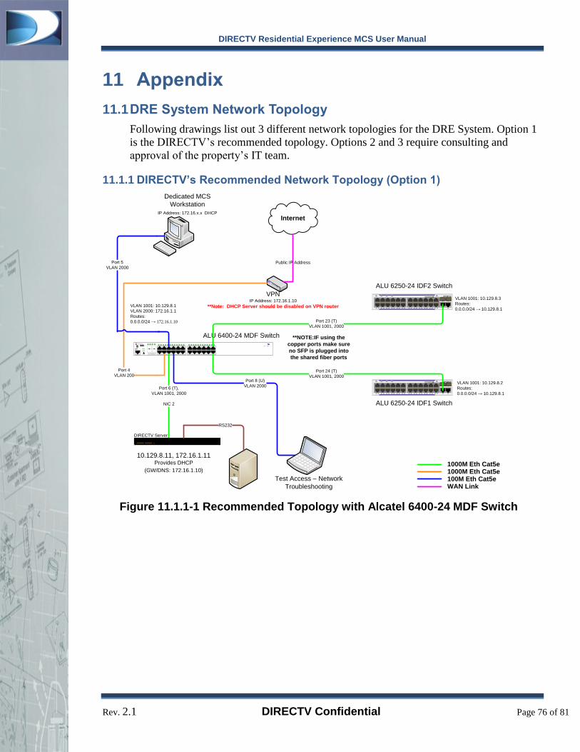
DIRECTV Residential Experience MCS User Manual
Rev. 2.1 DIRECTV Confidential Page 76 of 81
11 Appendix
11.1 DRE System Network Topology
Following drawings list out 3 different network topologies for the DRE System. Option 1
is the DIRECTV’s recommended topology. Options 2 and 3 require consulting and
approval of the property’s IT team.
11.1.1 DIRECTV’s Recommended Network Topology (Option 1)
OmniSwitch 6400-24
USB
CONSOLE
1 2 3 4 5 6 7 8 9 10 11 12 13 14 15 16 17 18 19 20 21 22 23 24
CLASS 1 LASER PRODUCT
OK PRI PWR BPS
31
42
10.129.8.11, 172.16.1.11Provides DHCP
(GW/DNS: 172.16.1.10)
ALU 6400-24 MDF Switch
Port 6 (T),
VLAN 1001, 2000
NIC 2
Port 8 (U)
VLAN 2000
Test Access – Network
Troubleshooting
Internet
VPNIP Address: 172.16.1.10
**Note: DHCP Server should be disabled on VPN router
VLAN 1001: 10.129.8.3
Routes:
0.0.0.0/24 → 10.129.8.1
CLASS 1 LASER PRODUCTOS6250-24
OK PRI PWR BPS
1 2 3 4 5 6 7 8 9 10 11 12 13 14 15 16 17 18 19 20 21 22 23 24 25 26
ALU 6250-24 IDF2 Switch
VLAN 1001: 10.129.8.2
Routes:
0.0.0.0/24 → 10.129.8.1
CLASS 1 LASER PRODUCTOS6250-24
OK PRI PWR BPS
1 2 3 4 5 6 7 8 9 10 11 12 13 14 15 16 17 18 19 20 21 22 23 24 25 26
ALU 6250-24 IDF1 Switch
1000M Eth Cat5e1000M Eth Cat5e 100M Eth Cat5eWAN Link
Port 24 (T)
VLAN 1001, 2000
Port 23 (T)
VLAN 1001, 2000
VLAN 1001: 10.129.8.1
VLAN 2000: 172.16.1.1
Routes:
0.0.0.0/24 → 172.16.1.10
Port 4
VLAN 200
Public IP Address
Dedicated MCS
Workstation
IP Address: 172.16.x.x DHCP
Port 5
VLAN 2000
DIRECTV Server
RS232
**NOTE:IF using the
copper ports make sure
no SFP is plugged into
the shared fiber ports
Figure 11.1.1-1 Recommended Topology with Alcatel 6400-24 MDF Switch

DIRECTV Residential Experience MCS User Manual
Rev. 2.1 DIRECTV Confidential Page 77 of 81
Public IP Address
OmniSwitch 6400-U24
USB
CONSOLE
1 2 3 4 5 6 7 8 9 10 11 12 13 14 15 16 17 18 19 20 21 22 23 24OK PRI PWR BPS
1 2
1 2
CLASS 1 LASER PRODUCT
NIC-1: 10.129.8.11, 172.16.1.11Provides DHCP
(GW/DNS: 172.16.1.10)
ALU 6400-U24 MDF Switch
Port 1 (T),
VLAN 1001, 2000
NIC 2
Port 2 (U)
VLAN 2000
Test Access – Network
Troubleshooting
Internet
VLAN 1001: 10.129.8.3
Routes:
0.0.0.0/24 → 10.129.8.1
CLASS 1 LASER PRODUCTOS6250-24
OK PRI PWR BPS
1 2 3 4 5 6 7 8 9 10 11 12 13 14 15 16 17 18 19 20 21 22 23 24 25 26
ALU 6250-24 IDF2 Switch
VLAN 1001: 10.129.8.2
Routes:
0.0.0.0/24 → 10.129.8.1
CLASS 1 LASER PRODUCTOS6250-24
OK PRI PWR BPS
1 2 3 4 5 6 7 8 9 10 11 12 13 14 15 16 17 18 19 20 21 22 23 24 25 26
ALU 6250-24 IDF1 Switch
Port 24 (T)
VLAN 1001, 2000
Port 23 (T)
VLAN 1001, 2000
VLAN 1001: 10.129.8.1
VLAN 2000: 172.16.1.1
Routes:
0.0.0.0/24 → 172.16.1.10
Port 4
VLAN 2000
Dedicated MCS
Workstation
IP Address: 172.16.x.x DHCP
Port 5
VLAN 2000
(Needs SFP)
DIRECTV Server
RS232
PMS Server
1000M Eth Fiber1000M Eth Cat5e100M Eth Cat5eWAN Link
**NOTE:IF using the
copper ports make sure
no SFP is plugged into
the shared fiber ports
VPNStatic IP Address: 172.16.1.10
*Note: DHCP Server has to be disabled on VPN Router
Figure 11.1.1-2 Recommended Topology with Alcatel 6400-U24 MDF Switch
Note: On the 6400-U24 MDF Switch, ports 1 & 2 are “Combo Ports”. When connecting the
MCS Server or Test Access PC to the copper ports 1 & 2, do not insert SFPs into fiber ports 1
& 2.

DIRECTV Residential Experience MCS User Manual
Rev. 2.1 DIRECTV Confidential Page 78 of 81
11.1.2 Option 2
OmniSwitch 6400-24
USB
CONSOLE
1 2 3 4 5 6 7 8 9 10 11 12 13 14 15 16 17 18 19 20 21 22 23 24
CLASS 1 LASER PRODUCT
OK PRI PWR BPS
31
42
ALU 6400-24 MDF Switch
Port 6 (T),
VLAN 1001, 2000
NIC 2
Port 5 (U)
VLAN 2000
Test Access – Network
Troubleshooting
Internet
Hotel’s Private Network
VLAN 1001: 10.129.8.3
Routes:
0.0.0.0/24 → 10.129.8.1
CLASS 1 LASER PRODUCTOS6250-24
OK PRI PWR BPS
1 2 3 4 5 6 7 8 9 10 11 12 13 14 15 16 17 18 19 20 21 22 23 24 25 26
ALU 6250-24 IDF2 Switch
VLAN 1001: 10.129.8.2
Routes:
0.0.0.0/24 → 10.129.8.1
CLASS 1 LASER PRODUCTOS6250-24
OK PRI PWR BPS
1 2 3 4 5 6 7 8 9 10 11 12 13 14 15 16 17 18 19 20 21 22 23 24 25 26
ALU 6250-24 IDF1 Switch
1000M Eth Cat5e1000M Eth Cat5e100M Eth Cat5eWAN Link
Port 24 (T)
VLAN 1001, 2000
Port 23 (T)
VLAN 1001, 2000
VLAN 1001: 10.129.8.1
VLAN 2000: 172.16.1.1
Routes:
0.0.0.0/24 → 172.16.1.10
Port 4
VLAN 2000
Ports 50, 443, 60443
500 and 4500 need to be
forwarded to the VPN router
Port 80 needs to be opened
to access MCS UI from
Hotel’s Private Network
RS232
DIRECTV Server
PMS Server
NIC2 :10.129.8.11, 172.16.1.113
NIC1:DHCP IP from Hotels Private NetworkProvides DHCP
(GW/DNS: 172.16.1.10)
VPNStatic IP Address: 172.16.1.10
*Note: DHCP Server has to be disabled on VPN Router
Figure 11.1.2-1 Option 2 with Alcatel 6400-24 MDF Switch

DIRECTV Residential Experience MCS User Manual
Rev. 2.1 DIRECTV Confidential Page 79 of 81
OmniSwitch 6400-U24D
USB
CONSOLE
1 2 3 4 5 6 7 8 9 10 11 12 13 14 15 16 17 18 19 20 21 22 23 24OK PRI PWR BPS
1 2
1 2
CLASS 1 LASER PRODUCT
Port 1 (T),
VLAN 1001, 2000
NIC 2
Port 2 (U)
VLAN 2000
Test Access – Network
Troubleshooting
Internet
Hotel’s Private Network
VLAN 1001: 10.129.8.3
Routes:
0.0.0.0/24 → 10.129.8.1
CLASS 1 LASER PRODUCTOS6250-24
OK PRI PWR BPS
1 2 3 4 5 6 7 8 9 10 11 12 13 14 15 16 17 18 19 20 21 22 23 24 25 26
ALU 6250-24 IDF2 Switch
VLAN 1001: 10.129.8.2
Routes:
0.0.0.0/24 → 10.129.8.1
CLASS 1 LASER PRODUCTOS6250-24
OK PRI PWR BPS
1 2 3 4 5 6 7 8 9 10 11 12 13 14 15 16 17 18 19 20 21 22 23 24 25 26
ALU 6250-24 IDF1 Switch
Port 24 (T)
VLAN 1001, 2000
Port 23 (T)
VLAN 1001, 2000
VLAN 1001: 10.129.8.1
VLAN 2000: 172.16.1.1
Routes:
0.0.0.0/24 → 172.16.1.10
Port 4
VLAN 2000
Ports 50, 443, 60443
500 and 4500 need to be
forwarded to the VPN router
Port 80 needs to be opened
to access MCS UI from
Hotel’s Private Network
RS232
DIRECTV Server
PMS Server
1000M Eth Fiber
1000M Eth Cat5e
100M Eth Cat5e
WAN Link
ALU 6400-U24 MDF Switch
VPNStatic IP Address: 172.16.1.10
*Note: DHCP Server has to be disabled on VPN Router
NIC-1: 10.129.8.11, 172.16.1.11Provides DHCP
(GW/DNS: 172.16.1.10)
**NOTE:IF using the
copper ports make sure
no SFP is plugged into
the shared fiber ports
Figure 11.1.2-2 Option 2 with Alcatel 6400-U24 MDF Switch

DIRECTV Residential Experience MCS User Manual
Rev. 2.1 DIRECTV Confidential Page 80 of 81
11.1.3 Option 3
OmniSwitch 6400-24
USB
CONSOLE
1 2 3 4 5 6 7 8 9 10 11 12 13 14 15 16 17 18 19 20 21 22 23 24
CLASS 1 LASER PRODUCT
OK PRI PWR BPS
31
42
NIC2 :10.129.8.11, 172.16.1.113
NIC1:DHCP IP from Hotels Private NetworkProvides DHCP
(GW/DNS: 172.16.1.10)
ALU 6400-24 MDF Switch
Port 6 (T),
VLAN 1001, 2000
NIC 2
Port 8 (U)
VLAN 2000
Test Access – Network
Troubleshooting
Internet
VPNStatic IP Address: 172.16.1.10
*Note: DHCP Server has to be disabled on VPN Router
VLAN 1001: 10.129.8.3
Routes:
0.0.0.0/24 → 10.129.8.1
CLASS 1 LASER PRODUCTOS6250-24
OK PRI PWR BPS
1 2 3 4 5 6 7 8 9 10 11 12 13 14 15 16 17 18 19 20 21 22 23 24 25 26
ALU 6250-24 IDF2 Switch
VLAN 1001: 10.129.8.2
Routes:
0.0.0.0/24 → 10.129.8.1
CLASS 1 LASER PRODUCTOS6250-24
OK PRI PWR BPS
1 2 3 4 5 6 7 8 9 10 11 12 13 14 15 16 17 18 19 20 21 22 23 24 25 26
ALU 6250-24 IDF1 Switch
1000M Eth Cat5e1000M Eth Cat5e 100M Eth Cat5eWAN Link
Port 24 (T)
VLAN 1001, 2000
Port 23 (T)
VLAN 1001, 2000
VLAN 1001: 10.129.8.1
VLAN 2000: 172.16.1.1
Routes:
0.0.0.0/24 → 172.16.1.10
Port 4
VLAN 200
Public IP Address
NIC 1
Router
DHCP IP Address
Hotel’s
Private Network
RS232
PMS Server
DIRECTV Server
**NOTE:IF using the
copper ports make sure
no SFP is plugged into
the shared fiber ports
Figure 11.1.3-1 Option 3 with Alcatel 6400-24 MDF Switch

DIRECTV Residential Experience MCS User Manual
Rev. 2.1 DIRECTV Confidential Page 81 of 81
OmniSwitch 6400-U24D
USB
CONSOLE
1 2 3 4 5 6 7 8 9 10 11 12 13 14 15 16 17 18 19 20 21 22 23 24OK PRI PWR BPS
1 2
1 2
CLASS 1 LASER PRODUCT
Port 1 (T),
VLAN 1001, 2000
NIC 2
Port 2 (U)
VLAN 2000
Test Access – Network
Troubleshooting
Internet
VLAN 1001: 10.129.8.3
Routes:
0.0.0.0/24 → 10.129.8.1
CLASS 1 LASER PRODUCTOS6250-24
OK PRI PWR BPS
1 2 3 4 5 6 7 8 9 10 11 12 13 14 15 16 17 18 19 20 21 22 23 24 25 26
ALU 6250-24 IDF2 Switch
VLAN 1001: 10.129.8.2
Routes:
0.0.0.0/24 → 10.129.8.1
CLASS 1 LASER PRODUCTOS6250-24
OK PRI PWR BPS
1 2 3 4 5 6 7 8 9 10 11 12 13 14 15 16 17 18 19 20 21 22 23 24 25 26
ALU 6250-24 IDF1 Switch
Port 24 (T)
VLAN 1001, 2000
Port 23 (T)
VLAN 1001, 2000
VLAN 1001: 10.129.8.1
VLAN 2000: 172.16.1.1
Routes:
0.0.0.0/24 → 172.16.1.10
Port 4
VLAN 2000
Public IP Address
NIC 1
Router
DHCP IP Address
Hotel’s
Private Network
RS232
PMS Server
DIRECTV Server
ALU 6400-U24 MDF Switch
1000M Eth Fiber1000M Eth Cat5e100M Eth Cat5eWAN Link
VPNStatic IP Address: 172.16.1.10
*Note: DHCP Server has to be disabled on VPN Router
NIC2 :10.129.8.11, 172.16.1.113
NIC1:DHCP IP from Hotels Private NetworkProvides DHCP
(GW/DNS: 172.16.1.10)
**NOTE:IF using the
copper ports make sure
no SFP is plugged into
the shared fiber ports
Figure 11.1.3-2 Option 3 with Alcatel 6400-U24 MDF Switch