Management and Operation Manual for Private …...Management and Operation Manual for Private...
46
Management and Operation Manual for Private Micro-Hydropower Plants Prepared by DCS – Technology Development P.O. Box : 8, Butwal, Nepal International Centre for Integrated Mountain Development (ICIMOD) Kathmandu, Nepal 1998
Transcript of Management and Operation Manual for Private …...Management and Operation Manual for Private...

Management and Operation Manual
for
Private Micro-Hydropower Plants
Prepared by
DCS – Technology Development
P.O. Box : 8, Butwal, Nepal
International Centre for Integrated Mountain Development
(ICIMOD)
Kathmandu, Nepal
1998
Table of Contents
1. Introduction Page
2. Plant Management 1
2.1 Operator’s Management 3
2.1.1 Selection and Terms of Employment 3
2.1.2 Training 4
2.1.3 Assignment and Supervision of Operator’s Work 4
2.2 Improving Customer Services 5
2.2.1 Public Relations 5
2.2.2 Good Service 5
2.2.3 Load Management 5
2.3 Financial Management 6
2.3.1 Income and Expenditure Account 8
2.3.2 Budget for Next Year 10
2.3.3 Business Expansion 11
2.3.4 Extending Supply 12
2.4 Organizing Maintenance 13
2.4.1 Maintenance Stock of Spares 13
2.4.2 Maintenance Tools 14
2.5 Organizing Repairs 15
2.5.1 Procedures to Deal with a Breakdown and Fault Diagnosis 15
2.5.2 Disassembling and Assembling the Equipment 16
2.5.3 Transporting Equipment for Repairs 16
3. Operation 18
3.1 General Operation Procedure 18
3.1.1 The Startup Procedure 18
3.1.2 Continuous Checks During Running 19
3.1.3 Shutting Down Procedure 19
3.2 Safety and First Aid 20

3.2.1 Workplace Safety Precautions 20
3.2.2 First Aid for Electrical Shock 21
3.2.3 Artificial Respiration Techniques 21
3.3 Extended Shut Down 23
3.4 Routine Inspection and Maintenance 23
3.4.1 Daily Inspection and Maintenance 24
3.4.2 Weekly Inspection and Maintenance 24
3.4.3 Monthly Inspection and Maintenance 24
3.4.4 Six Monthly Inspection and Maintenance 24
3.4.5 Yearly Inspection and Maintenance 25
3.4.6 Additional Inspection and Maintenance 25
3.4.7 Some Additional Suggestions Regarding Operation and 25
Maintenance
3.5 Log Book 26
4. Transmission & Distribution 29
4.1 House Wiring 31
4.2 Earthing 34
4.3 General Rules for House Wiring 34

PREFACE
The main objective of preparing and distributing this Manual on management and operation of
private or community owned/managed MMHP plants (especially the micro-range) is to provide
some assistance to the managers and operators who are otherwise facing difficulties in this
regard. Such difficulties have mainly emerged since the managers and operators of such plants
are less educated, less exposed to machinery and have very few opportunities to participate in
relevant and quality training programmes.
The preparation of the Manual was visualized, initiated and sponsored by ICIMOD as a regular
component of NORAD-sponsored project "Capacity Building for Mini- and Micro Hydropower
Development in the Selected Countries of Hindu Kush-Himalayan Region, Phase II". It is one
of five such manuals aimed at the various groups of implementers, including; site surveyors
and layout designers,-manufacturers of indigenous equipment, installers, managers and
operators - and the repairers. The first draft of this Manual was prepared by DCS-Technology
Development Butwal, Nepal and was extensively revised by me. Thus, this is a first indigenous
and concerted effort to write quality manuals having a regional rather than general perspective.
DCS, in particular, deserves acknowledgement and encouragement.
The main focus of this manual concerns the isolated, indigenous, local entrepreneur-owned
.plants in the micro-range. But mostly, such plants installed in Nepal, Pakistan and India have
capacity less than' 60 kW. Keeping in mind that the. managers and operators of such plants
have very little education and even less technical knowledge, the manual has been kept simple
and brief. For the same reason, the manual does not cover all different types of machines and
management systems. In any case, it is almost impossible to cover all the managerial and
operational aspects in one manual of this type. At the same time, one should always strive to
improve such documents. Therefore, suggestions to improve it further and make it reasonably
useful are welcome, indeed earnestly solicited from experienced implementing agencies and
operators/managers who may be able to point out the additional aspects to be covered and the
methodology.

The above remarks not withstanding, it is hoped that manual in the relevant languages in India,
Nepal and Pakistan would provide significant assistance and relief to the practicing managers
and operators. It is also hoped that some training agencies would find it to be a useful support
mater . al for their training programmes.
Anwar A. Junejo Coordinator, MMHP Project ICIMOD

ACRONYMS:
PTC -> Positive Temperature. Coefficient
ECC -> Electronic Current Cutout
LPC -> Load Priority Controller
NGO -> Non Government Organisation
kW -> Kilowatt
BPT -> Break Pressure Tank
ELC -> Electronic Load controller
MCB -> Miniature Circuit Breaker
ADB/N -> Agriculture Development Bank/Neal
ITDG -> Intermediate Technology Development Group
VIR -> Vulcanized Indian Rubber (Insulation)
PVC -> Poly Vinyl Chloride
TRS -> Tough Rubber Sheathed (Insulation)
SOE -> Sundhara Oil Expeller
DP -> Double Pole (Switch)
MMHP -> Mini- and Micro-Hydropower
MHP -> Micro- Hydropower

INTRODUCTION
To develop any village, region, or even a country'. proper resource mobilization, whether
human or natural, plays a vital role. In the Hindu Kush-Himalayan (I-IKH) region there are
few natural mineral resources of worth, except abundant water resources and a large pool of
human resources, although unskilled. Using currently available technology, which is based on
practical, installation experience, micro- and mini-hydropower (MMHP) can be installed to
harness this available water resource; and combined with the human resource, through training,
can play a significant role in enhancement of living standards in the remote and under-
developed mountain areas.
As we-approach the 21" century, electricity is no longer considered to be a luxury, but a basic
need of people everywhere. It is synonymous with a better standard of living and is vital for
better communications, health care and reduced physical labour.
Installation of equipment is not the end of the job many project. Proper o pertain and
management of the plant and organising repair and maintenance are also essential for
satisfactory performance which can be achieved through training and back-stopping. Indeed,
proper management of these stages is the main determinant in the success or failure of the
entire project.
In HKH region, settlements and houses are scattered and remote from road heads or national
grid. Transmission of electricity or transport of fuel to many of these locations is
prohibitively expensive. Therefore, old forest trees are being felled, with few new plantations
to replace them, to provide firewood for cooking, commercial use and even lighting. Such
deforestation also contributes towards flash floods and landslides. Some practical options to
mitigate these problems are new plantation programme and use of MMHP to meet the local
energy needs.
The capital required for investing in MMHP is beyond the reach of the people of mountain
communities and loans must be taken. If these loans are not to be a burden; the MMHP

schemes must be carefully scrutinized, installed and wisely operated and managed (including
proper repair and maintenance) to give long-term benefits. If properly installed, a MMHP
plant may provide energy for lighting, grain grinding, oilseed expelling and other milling
facilities, as well as for possible use of communication by phone, radio and television; and
industries such as sawmills, papermills, Workshops, etc. It may even encourage facilities
such as ropeways, to reduce the burden of physical pottering.
This manual has been prepared to assist in management of MMHP plants so as to give
maximum returns and benefits from the investment. It assumes that the survey, design,
installation and hand-over work has been completed amicably. The roles of operator and
manager now become as important to the investors in the project as the role of a bus driver is
to the safe operation of a bus. Carelessness on behalf-of either may result in an accident.
The manual is intended for the use of managers and operators of micro-hydropower (MHP)
plants of upto 100 kW capacity. However, many chapters may also be relevant for larger
MMHP plants of, say, up to 200 kW capacity. However, since the manual does not contain
chapters on transformers or high-transmission transmission lines, such information would have
to be acquired from other sources.
Ideally, the manual would be more useful for those managers and operators who have also
attended a training programme based on this manual. However, those serving managers and
operators may also find it beneficial who know the MHP plants and their parts reasonably well
and their reading capabilities are adequate. Basically, the manual has been written for
electrification schemes. However, the MHP plants (prime movers) powering other industrial
applications such as agro-processing can equally benefit from the contents of this manual.
2. PLANT MANAGEMENT
In small plants the operator and manager is usually the same person; or, the manager also
assists in operation and maintenance. For plants larger than 50 kW, there should be two
different positions; both for a manager and operator; but this again depends on the level of

management skill of the operator and also the interest and commitment of the manager who
may also be the owner of the plant.
The operator is responsible for not just running the plant but also for maintenance and
occasional repair. Therefore, he must understand the location and functions of each machine
and components. He should be continually listening, testing and checking for malfunctions and
problems. He needs. to keep uppermost in mind that prevention is always better than cure - "a
stitch in time saves nine". His responsibility will normally be for all equipment and structures
from source to distribution including routine inspections, operation, loading of the system,
distribution and good condition of equipment.
The manager is responsible for overall management of the plant including organization,
planning, management, budgeting, tariff setting, keeping of books, etc.
2.1 Operators' Management
2.1.1 Selection and Terms of Employment
Management selects and appoints the operator who should be suitable for the job. The operator
should be at least literate, preferably educated upto class 8 if possible; he should be
experienced, sincere, honest and having the capacity to learn and build good relationship with
others. He should be able to do basic trouble-shooting. If not, he should be trained properly by
good trainers at a suitable Location; including at a running MHP plant.
A suitable local person should be selected as operator if possible, because he is less likely to
leave the job. This may not always be possible though; in which case a more experienced
person should be selected from outside and a higher salary offered. A more qualified person
will run the project more smoothly and his higher salary is more likely to keep him there.
An operator can work 8 hours a day normally; but if the plant runs for more than 8 hours per
day, an additional operator will be needed to cover illness and emergencies also. If the
owner/manager is capable of running the plant, he may take the place of an emergency

operator. Two operators should be appointed if the plant has agroprocessing plus electrical
generator.
Details of salary, leave, overtime and other facilities should be made clear at the time of
appointment and it is recommended that a contract be drawn up covering all important
conditions so as to avoid disputes later. Terms of resignation and period of notice by both sides
should also be specified in the contract. The operator should preferably be appointed during
the equipment installation stage of the project and be required to work along side the installers
so that he learns about the procedure of installation, assembly, etc. If possible, installers should
explain to the operator about what can go wrong with each component and how to run the
equipment, apply tension to belts, grease the lubrication points and how to deal with
emergencies.
If the plant is coupled to agro-processing equipment, the operator should also be trained to
operate the agro-processing equipment and its accessories; i.e. shaft pulley, belt, etc. The
operator should know how to change belts safely, how to fix alignment and diagnose faults of
agro-processing machines. If the operator leaves the job after only a short time it will not only
hinder the day to day work but also cause economic loss to the owner. It is, therefore,
important to select those people who have little chance of leaving the job. Adequate incentives
including good salary may be helpful in retaining good operators, in addition to good behaviour
and treatment.
2.1.2 Training
If the operator / manager is hired in the early phases of the project, the subsequent training
needs may be less. It is, however, necessary to provide special training, if the employee is
hired after the handover of the project. The owner/community should be aware of the ii-
importance of training, without which a project will not run smoothly. The installer provides
some basic training at the project site, to familiarize the operator with the machines and simple
operational procedures. Usually this training may not be adequate. Therefore, additional
extensive training should also be provided. There are organizations which provide such
training throughout the year. Often the training is given free of cost. The owner/community
should make themselves aware of such opportunities available in their country.
2.1.3 Assignment and Supervision of Operator's Work
The number of powerhouse operators needed by a micro-hydro project and their work
assignments are determined by the capacity of the project, the complexity of the transmission
lines, headrace, penstock, etc. The usual work load of the operators can be classified as
follows.
♦ Regularly inspecting the civil works and penstock for damage and cleaning up.
♦ Flushing / cleaning the intake, headrace, desilting basins, forebay, etc.
♦ Repairing damage to civil works.
♦ Stabilising / cleaning surrounding areas to avoid landslide damage.
♦ Cleaning and properly maintaining the powerhouse and the equipment there.
♦ Properly operating the machines within the powerhouse.
♦ Listening for any malfunction or similar problems.
♦ Shutting down the plant if necessary.
♦ Carrying out some minor repairs.
The job of the manager is to clearly explain these assignments to the operators, to assist and
lead them, and to supervise their work, especially during the initial stages of their allotment.
The manager should also assess the quacks of the o aerators to learn and perform their duties
amicably. He must also question them or reprimand them if necessary about any laxness in
performing their duties.
2.2 Improving Customer Services
2.2.1 Public Relations
The manager and operator should be gentle in speech to the customers which is good for
siness. Any minor problems- with the customers should be sorted out immediately. For

complex problems, a general meeting should be called, inviting all related personnel. The
prevailing problems should be discussed and a solution worked out jointly, especially in case of
electrification schemes. Sometimes the operator / manager himself may have to visit the local
workshop or organization remote from the plant. During this period, another capable person
should be instructed to look after the operation and management of the plant. The public
should be informed in advance of the approximate period and reasons for any shut downs of the
plant so that they can make alternative arrangements.
The operator/manager of an electrification plant should visit the consumers and discuss with
them problems or complaints they may have regarding the supply; and discuss other issues
such as use of electricity, non payment of bill, low voltage, etc. Every effort should made to
hold such discussions in a cordial manner..
2.2.2 Good Service
The operator/manager must provide good service to the customers on a first-come firstserved
basis with few exceptions. For example, people coming from distant places need to go home
early, so they may be given priority after reaching an understanding with other customers.
While planning the supply of electricity, all houses requesting a fixed wattage supply, should
be connected first. Only after all such houses have been provided for, additional available
power should be distributed as per the requirements.
Unscheduled and unannounced shut down of the plants would lead to loss of revenue, business
and reputation. Therefore, every effort must be made to avoid the breakdowns and shutdowns,
through regular maintenance and taking care of small faults and problems which may-
eventually lead to serious break downs.
2.2.3 Load Management
Power demand will exceed the installed capacity sooner or later in many plants because,
unfortunately, some consumers may take more power then the amount they have subscribed
for. There is a need for some sort of monitoring device to make certain that the generating

plant is not over-loaded and the investor is not suffering losses. It is not practical to install a
meter in every house-hold in a MHP scheme. This will only introduce more costs and
complications; especially since most consumers will be subscribing in the range of 50-200
watts only.
A flat rate system is generally used, and in this the consumers pay a fixed rate for wattage
he/she subscribes to. Positive Thermal Coefficient (PTC) controllers are use for 25 to 50 watt
range, electronic current cut-outs (ECC) are available for 50-200 w arrange, and miniature
circuit Breakers (MCB) are suitable for consumers subscribe for more than 200 watts.
However, some problems have been experienced when ECC were used in Nepal. The other
two options may, therefore, be used.
Load factors of MHP plants are generally poor, especially the electrification schemes The main
use of electricity is for domestic lighting. Thus the power demand is of certain hours in the
evenings and sometimes in the mornings for about six hours a day While, the available power
from the plant remains unutilized for the remaining period resulting in less income. The
owner/manager must, therefore, always think of ways increase utilisation and/or sale of
electricity particularly to industrial or commercial units.
During the daytime and at night, when lighting is not necessary, other end uses could be
installed such as, small industries, shops with ' refrigerators, bakeries, sawmills, and so on. The
owner of the MHP plant may invest in such applications himself; or he ma encourage or seek
others to install such units and buy electricity from him. If industrial uses can be enhanced,
power distribution must be carefully managed to be acceptable to such customers.
Sometimes due to high costs, there is a lack of interest in industrial development. The manager
should motivate people to install industries, and charges should be reduced if the investors
agree to operate during off peak hours. Industries should, wherever possible, not be run during
peak hours; otherwise there will be voltage fluctuation. Rates for such industries should be
decided before the industry is installed.

2.3 Financial Management
In order to keep track of income and expenditure, proper records and accounts of the income,
expenditure and savings should be maintained. ' Repayments of the loan should be planned,
based on the income and the savings and adequate amount must set aside each month for this
purpose. An account book maintained for this purpose, must cover the following.
♦ Daily records. of income and expenditure including the outstanding amounts.
♦ Records of Assets (property and stock owned, liabilities/bills or money still to be paid,
on monthly basis.
Amounts spent on major repairs, new equipment or business expenses- should also be recorded
daily and separately on monthly basis.
♦ All the income, expenditure, outstanding income and liabilities must be reproduced in a
final table each year to determine net profit or loss. These calculations would be useful
for planning the business for the next year.
♦ Usually, one Account Book would be sufficient for a MHP plant, but it should have
many tables.
There are two main systems for. keeping the accounts of a project; i.e. single entry book-keeping,
where the transactions are recorded once, and double entry bookkeeping, where all the business
transactions are recorded twice. For example, when a MHP project purchases spare parts, the spare's
account will be increased and the bank account or cash account will be reduced. This double entry
book-keeping system is prefered because it is a more systematic and professional method of
maintaining accounts, and can help identify mistakes very easily. However, for smaller MHP
schemes; say below 50 kW, the double entry system may be unnecessarily cumbersome and single
entries both for income and expenditure may be good enough.
An example of book-keeping for a 30 kW, MHP scheme is illustrated in the following tables.

Table 2.1 Details of Total Project Cost
S.No. Description Amount (Rs.)
1 Land purchased 50,000
2 Civil construction (Canal, powerhouse, desilting basin, forebay) 300,000
3 Mechanical equipment (turbine, penstock, driving systems) 335,000
4 Electrical (Generators, ELC, components, etc.) 1,000,000
5 Transportation cost 100,000
6 Installation cost 200,000
7 Operator training 15,000
8 Total Cost Rs. 2,000,000
Sources of funds
1 Local contribution or self investment) 400,000
2 grammar from NGO 500,000
3 Loan from Bank 600,000
4 Subsidy 500,000
Total Rs. 2,000,000
This Table should be provided on the First Page of the Account Book.
Table 2.2 Loan Repayment Schedule for the MHP Plant
Description Amount
Complete repayment in 7 yearly installments 600,000
Ist yr. Ending June, 1997 – repayment of capital 86,000
Interest on 600,00 @ 16% 96,000
Ist installment of loan and interest to be paid by 15 July, 1997 182,000
2nd yr. Ending 30th June, 1998 – repayment of capital 86,000
Interest on 514,000 @ 16% 82,240
2nd installment of loan and interest to be paid by 15 July, 1998 168,240
3rd yr ending 30th June, 1999 – repayment of capital 86,000

Interest on 428,000 @ 16% 68,000
Interest on 428,000 @ 16% 68,480
3rd installment of loan and interest to be paid by 15 July, 1999 154,480
4th yr ending 30th June, 2000 repayment of loan 86,000
Interest on 3.42,000 @ 16% 54,720
4th installemtn of loan and interest to be paid by 15 July, 2000 140,720
5th yr ending 30th June, 2001 – repayment of loan 86,000
Interest on 2,56,000 @ 16% 40,960
5th installment of loan and interest to be paid by 15 July, 2001 126,960
6th yr ending 30th June, 2002 – repayment of loan 86,000
Interest on 170,000 @ 16% 27,200
6th installment of loan and interest to be paid by 15 July, 2001 113,200
7th yr. ending 30th June, 2003 –repayment of loan 84,000
Interest on 84,000 @ 16% 13,444
7th installment of loan and interest 97,444
The total amount of loan Rs. 600,000 at an interest rate of 16%.
This Table should be reproduced on page 2 of the Account Book for easy reference.
2.3.1 Income and Expenditure Account
The manager or owner of the project should maintain records in the Account Book (ledger) similar to
the example given below in Table 2.3. All income should be dated, and sources of income and
expenditure clearly detailed. There will be different expenditures such as salaries, travel, other
expenditures and loan installment. The Account Book should be updated daily and all transactions
recorded in chronological order. Pending incomes to be received and necessary expenditure may be
noted down separately but not accounted until they are actually received or undertaken. The final
figures of income and expenditure should also be worked out for each month and year.

Table 2.3 A Sample of Daily Entries in an Account Book for Month of January,1998
Date Description Credit Debit Balance (Income) (Expenditure) (Net Income)
Ist Jan, '98 Money in hand (opening 10,000
balance)
Ist Jan, '98 income from electricity sale 10,000
from Area 1, 100 customers @
Rs. 1 00 each
Ist Jan, '98 Salary for two staff a 1500 - 3,000
each for December 97
Ist Jan, '98 Travel expenses paid - 250
Ist Jan, '98 Repair & maintenance expenses - 500
for canal
Ist Jan, '98 Stationery (Postage & - 10
Telephone paid)
Ist Jan, '98 Other expenses - 5
2nd Jan, '98 Plant closed due to festival -
3rd Jan, '98 Sale of electricity from area 7,500
No. 2,
75 customers @ Rs. 100 each
4th, Jan, '98 Sale of electricity from area 3,000
No.3
30 customers a Rs. 100 each
5th Jan, '98 Sale of electricity from area 2,000
No.4
20 customers @ Rs. 100 each
Total for January 1998

At the end of each year it would be useful if incomes and expenditures of all major headings are recorded
on a single page for such things as loan repayment, repairs, income from electricity, agro-processing, etc;
as shown in the example in Table 2.4. In this table the remaining net balance can be used for the personal
or family expenditure of the owner/investor.
For electricity sales, it, is unlikely that cash payments will be made in the beginning of every month.
Sometimes, money is not received until the following month. In such cases record of pending payments
due at the bottom of the first page of the month should be maintained which should be struck off and
entered as a regular entry in the Account Book when received.
Table 2.4 Incomes and Expenditures under various heads for 1998
Description Credit Debit Balance (Income) (Expenditure) (Net Income)
Balance from 1997 21,000
Income from electricity 270,000
Income from Agro-processing 180,000
Income from sale of Agro- 215,000
processing commodities
Income from sale of Agro-residues 13,000,
Salary of Staff 36,000
Maintenance 18,000
Repair of generator 40,000
Purchase of spares 14,000
Stationary, telephone 600
Loan Installment (Capital + Interest) 154,480
Travel & transport 19,000
Total 699,000 282,086 416,914

Net yearly income for 1998 Rs. 416,914
Net average monthly income Rs 34,743
2.3.2 Budget for Next Year
Keeping in mind the income, expenditure and net profit of previous 2-3 years, it is advisable to prepare
budget for the next year, say year 1999. The owner/manager should prepare another table (Table 2.5) on
the next page of the Account Book 'after Table 2.4 showing anticipated incomes and expenditures for
the next year and planning for some additional expenditure, say; major repairs, expansion of forebay,
cleaning and repairs of penstock, etc. The expenditure must also include personal needs of owner and
show the net savings which can be spent for repairs or for buying some new equipment. The final
figures in the Table show that the owner has to arrange additional Rs. 27,000 from his own resources if
he decides to go ahead -with his plans. He must also realize that the actual expenditure may be
significantly different from the anticipated figures recorded in the budget.
Table 2.5 Proposed Budget for the Year 1999
Description Credit Debit Balance (Income) (Expenditure) (Net Income)
Balance/saving from 1998 50,000
Anticipated
Income/Expenditure
Income from Electricity 280,000
Income from Agro-processing 150,000
income from sale of commodities 210,000
Income from other sources 20,000
Salary of staff 38,000
Maintenance 20,000
Purchase of Spares 10,000
Travel, training, etc. 10,000
Loan installment 168,240

Other expenditure 11,760
Expenditure on self 240,000
Total 710,000 497,000 213,000
Proposed additional expenditure
Purchase of Chiura (beaten rice) 150,000
machine
Installation of new equipment 30,000,
Equipment repair including 60,000
penstock
Total 240,000 - 27,000
2.3.3 Business Expansion
Installation of additional end use equipment and/or supplying electricity to additional customers
especially during the off peak hours should be one of the main considerations of the
owner/manager of an MHP plant, after he has achieved success in operating and managing the
current end uses optimally. One such example is shown below where the owner/manager of an
existing electrification scheme decided to add some agroprocessing equipment to his plant to
utilise additional power and thus earn more income. The cost of the new equipment and
expected yearly returns are given in Table 2.6, which suggests that the simple payback period is
about 4 years. This means also that the simple rate of return is about 25%; a healthy profit. One
could suggest more complicated methods of financial analysis. However, since the overall
investment is small, these simple figures may be adequate for the initial feasibility.
Table 2.6 Estimated Income and Expenditure for the New Agro-processing
Equipment
Description Credit Debit Balance (Income) (Expenditure) (Net Income) Capital Costs
Cost of grinder, huller and oil expeller 100,000
Other mechanical equipment 50,000
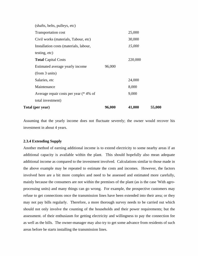
(shafts, belts, pulleys, etc)
Transportation cost 25,000
Civil works (materials, Tabour, etc) 30,000
Installation costs (materials, labour, 15,000
testing, etc)
Total Capital Costs 220,000
Estimated average yearly income 96,000
(from 3 units)
Salaries, etc 24,000
Maintenance 8,000
Average repair costs per year (* 4% of 9,000
total investment)
Total (per year) 96,000 41,000 55,000
Assuming that the yearly income does not fluctuate severely; the owner would recover his
investment in about 4 years.
2.3.4 Extending Supply
Another method of earning additional income is to extend electricity to some nearby areas if an
additional capacity is available within the plant. This should hopefully also mean adequate
additional income as compared to the investment involved. Calculations similar to those made in
the above example may be repeated to estimate the costs and incomes. However, the factors
involved here are a bit more complex and need to be assessed and estimated more carefully,
mainly because the consumers are not within the premises of the plant (as is the case 'With agro-
processing units) and many things can go wrong. For example, the prospective customers may
refuse to get connections once the transmission lines have been extended into their area; or they
may not pay bills regularly. Therefore, a more thorough survey needs to be carried out which
should not only involve the counting of the households and their power requirements; but the
assessment. of their enthusiasm for getting electricity and willingness to pay the connection fee
as well as the bills. The owner-manager may also try to get some advance from residents of such
areas before he starts installing the transmission lines.

The capital cost estimates may then be prepared along with estimates of income and recurrent
expenditure. Usually, the net incomes from the electrification schemes are quite small and the
net yearly incomes of about 15 per cent of the original investment may be considered adequate.
If, however, it becomes necessary to obtain a loan on normal interest from a financial institution,
then the project may not be viable and -possibilities of getting a subsidy or grant from a donor
agency may be explored.
2.4 Organizing Maintenance
To maintain the MHP plant in the best possible condition, it is essential that routine maintenance
be carried out in accordance with a predetermined schedule. Manufacturer's maintenance
schedules for items like bearings and generators should be followed carefully. Routine
preventative maintenance will result in extended plant life and reliable operation; and reduce the
long-term operating costs. Waiting for the plant to break down, then trying to fix it will result in
increased long-term operating costs, reduced plant life and user dissatisfaction.
The manager should clearly instruct the operator to check items outside and inside the
powerhouse on a regular basis to ensure reliable operation. He should also randomly supervise
his work. Problems if any, should be rectified as soon as possible to prevent them getting worse.
2.4.1 Maintaining Stock of Spares
A micro-hydro scheme needs repair and maintenance quite often and the manager is responsible
to organise it. Some spare parts should always be kept in stock, such as bearings, tools, grease,
oil, belts, etc; to avoid delays in procuring them when they are needed. Bearings, should be

stored in the original packing; if this was not possible, then they should be coated with grease.
Vee or flat belts need to be hung on a wall and not left coiled on the floor. Electrical parts
should be packed, labeled and stored away from moisture. The storage area should be clean and
secure.
It is recommended that one set of following spare parts should be kept in stock for an MHP
Plant.
♦ Turbine bearings 1 set (usually two)
♦ V-Belts 1 set
♦ Flat belts Adequate length enough to cover
the longest belt length used in
the plant.
♦ Grease 1 kg.
♦ Generator bearings 1 set
♦ Gaskets 1 set (for all locations)
♦ Penstock nuts, bolts 5% of total installed
♦ Expansion joint gasket 10% of total installed
♦ Fuses All installed sizes
In addition, if the funding permits, one turbine runner and an AVR should also be kept i stock
as spares.
2.4.2 Maintenance Tools
To enable the MHP plant to be kept well maintained, good quality tools are essential. manager
should be responsible for keeping the tools properly and should instruct guide the operators to
use them properly. The following suggestions will help keep tools in a good useable condition.
♦ Clean tools after use and return them to storage area.
♦ Lubricate them to prevent corrosion wherever necessary.

♦ Keep a record of tools.
♦ Do not throw tools, handle with care.
♦ Use tools as they are meant to be used.
♦ Check condition of tools and don't use damaged tools.
♦ Purchase new tools or repair them if they become unusable.
♦ Store hand tools on a board or in a cupboard.
♦ Store measuring instruments (multi-meter, vernier, etc.) in a cupboard or a draw
to protect them from dust and impact.
The spares and tools should preferably be kept in a separate room under lock and key and
record of their issuance and re-storing must be kept in the log book or a separate register. Fig.
2.1 gives some idea about proper storage of the tools.
Desirable Tools
The following is a list of tools which will be useful in the maintenance of a MHP scheme.
Electrical
♦ Combination pliers
♦ Nose pliers
♦ Soldering iron and solder
♦ Hacksaw
♦ Line tester and multi-meter
♦ Torch or portable lamp
In addition, if funding is available; one wirepuller and safety belt should also be kept in the
stock.
Mechanical
♦ Hammer

♦ File set (flat, -round, etc)
♦ Open and ring spanners, one set each
♦ Slide wrench (200 mm. or 300 mm.)
♦ Screw drivers (large, small)
♦ Phillips head screw driver (medium, small
♦ Grease gun
♦ Metric Allen key set
♦ Bench vice and vice grip
♦ Portable hand drill
♦ Twist drill set
♦ Measuring tape
♦ Paint brush
♦ Oil can
♦ Hack saw
♦ Wire brush
♦ Emery paper (various sizes)
Civil
♦ Pick
♦ Spade
♦ Shovel
♦ Crow bar (lever)
2.5 Organizing Repairs
2.5.1 Procedures to Deal With a Breakdown and Fault Diagnosis
When a breakdown occurs, necessary steps need to be taken to prevent further damage to the
plant and possible injury to staff. This usually requires shutting down of the plant until the
fault is diagnosed and the problem is rectified. Refer to the 'Manual for Maintenance and
Repairs of MHP Plants' for problem diagnosis and corrective action.


2.5.2 Disassembling and Assembling the Equipment
Before commencing disassembly work, always study carefully the layout of the unit to be
dismantled. Decide which components need to be removed and which do not. The manager
should decide whether a faulty part or machine can be repaired locally or it should be
transported to the manufacturer. If it is not locally repairable and the operator is not
experienced, then components which do not need to be removed should not be removed. With
any disassembly and re-assembly there is always a chance of equipment damage and waste of
time. However, in some situations where the transportation has to be manual; some heavier
parts may be removed and not transported. For example,, if the turbine runner or shaft is,
damaged, then it may be cumbersome and unnecessary to carry the whole turbine to the
repairers. On the other hand, if the shaft needs to be repaired then it may not fit or align
properly in the casing and/or bearing housing after it has 'been repaired. These are the types of
decisions that need to be taken by the managers when the repairs need to be organised.
Obviously, the wrong decisions would result in delays, extra expenditure and sometimes more
damage to the equipment.
The manager should only allow the operator to do local repairs if he is well experienced. The
manager or operator should have a basic knowledge' of electricity. Minor carelessness can also
cause serious equipment damage, personal injury or death when dealing with electricity
especially if electrical equipment is incorrectly assembled or wired, or not properly earthed.
2.5.3 Transporting Equipment for Repairs
More complicated repairs to items such as generators, runners and electronic equipment may
need to be carried out by the manufacturer or other competent repairer at his premises.
Transport of these items from site may be difficult due to poor access. It is, therefore,
important that before transportation,. care is taken to:
♦ pack equipment well using timber or thick cardboard;
♦ protect equipment from water damage by wrapping it in plastic;
♦ print the 'right way up' and 'handle with care' signs;
♦ inform persons responsible for transport about the need for care in handling, especially
when loading and unloading from vehicles.

Figure 2.2 also illustrates a few 'rights and wrongs' with regard to transportation of the
equipment.
3. OPERATION
Correct operation and maintenance of a MHP plant is beneficial in many Managers and
operators must be fully familiar with the equipment, its functions a operational procedures.
Technical specifications must also be known and pr( recorded in the Operations &
Maintenance Manual provided by the installer. and a the Log Book. An example of
specifications is given in Table 3.1 (p. 26-27).
3.1 General Operation Procedure
The following checks should be made during starting, stopping and running of plate any stage a
problem is noticed; say, unusual sound, the plant should be stop problem rectified before
starting or running the plant.
3.1.1 The start up procedure
For Water and Turbine
♦ Follow the specified procedure for cleaning up the civil works as applicable
♦ Visually inspect all equipment (e.g. turbine, generator, control panel, is switch, etc.).
♦ Check oil levels in any equipment using oil reservoirs.
♦ Ensure that penstock and turbine valves are closed.
♦ Turn on water at intake.
For Electricity
♦ Check that all switches on the load side are in the "OFF" position (if an E installed), or;
♦ Check that all switches on the load side are in the "ON" position (if there ELC).
♦ Inform users that plant will be starting (some system needs to be developed
operationlised, since it is difficult to inform all the consumers). If belts are removed,

put them on the pulleys, check belt tension also. Gradually open the penstock valve (if
fitted) to fully open position. Gradually let water into the turbine by opening the
turbine valve, while chek the pressure gauge to maintain smooth rise in pressure.
♦ If there are any push button switches for exciting the generator, press the voltage rises
up to 200 V.
♦ Increase water flow by opening turbine valves further until the speed, and power comes
up to desirable/rated level.
♦ For plants having ELC, gradually divert power to the. load by switching the load
switches.
♦ If there is no load controller increase the water flow until the voltage rises 220 V while
the load is connected.
♦ The allowable voltage fluctuation, for plants below 25 kW is + 10% a 14%; for larger
plants it should be within ± 10%.
For agro-processing
♦ Check all nuts, bolts, etc. of agro-processing machinery; move everything away from
the drive system.
♦ Engage the belt from the turbine to the line shaft and then to the machine.
♦ If there is no line shaft, place the belt directly from the turbine to the machine; for
example, rice huller.
♦ Admit grains to the huller, oil seed to the expeller, etc.
♦ Let water into the turbine, gradually opening the turbine valve until the required speed
is reached.
♦ Check the pressure gauge to ensure that pressure is not fluctuating rapidly.
♦ Listen for any abnormal noise or vibration when the unit is running. Stop the turbine if
this happens and look for the fault.
♦ Check drive systems (belt, coupling, etc.)
♦ Connect only those units simultaneously for which power is sufficient.

♦ If the turbine is powering a generator and agro-processing equipment simultaneously;
priority goes to electricity and connect the agro-processing unit only if sufficient
additional power (i.e flow) is available.
3.1.2 Continuous Checks during Running
The following checks are to be made during the running of the plant. If at any stage an
abnormal condition arises, the plant should be shut down and the problem diagnosed and
rectified.
♦ Every hour check voltage, frequency and power output and record in the log book once
a day. Abnormal readings must be recorded whenever noticed along with the corrective
action taken.
♦ If voltage or frequency decreases due to over-load, remove some loads.
♦ Check for abnormal noises and water leaks.
♦ Check bearing and generator temperatures by touching the housings.
♦ Periodically check penstock pressure.
♦ Compute consumed power from panel meter (current and voltage) if watt-meter is not
installed.
♦ If the power consumption is more than design capacity, disconnect some load from the
distribution box.
♦ If over-load occurs, it could be that some consumer is using a higher load (i.e. heater,
etc.) than permitted so checks should regularly be made at the premises of such type of
users,
3.1.3 Shutting down procedure
Following procedure should be followed prior to and during shutting down of. the MHP plant.
♦ Inform users that the plant will be shut down, if time permits (unless they already know,
in the case of regular shut downs).

♦ Switch 'OFF' all connected load.
♦ Close turbine control valve gradually to prevent rapid penstock pressure rise.
♦ Close penstock valve.
♦ Stop water from forebay tank and intake if necessary.
♦ Ensure that powerhouse and equipment are clean and tidy.
If the shut down is due to an emergency, the actions should be quick and emergency devices
such a jet deflectors (for Pelton turbines) should be actuated.
3.2 Safety and First Aid
While working with electricity, if we do not take adequate care, it can be very dangerous even
though it has some benefits. It is thus important to be aware of and remember safety
precautions, and even more essential; to know how to perform first aid and primary treatment
when an accident happens.
3.2.1 Workplace Safety Precautions
Following precautions may taken while operating an MHP scheme or even working in a
powerhouse while it is in operation.
1. If possible, shoes should be rubber soled; they must not be damp or wet.
2. While working, hands should not be wet.
3. Before starting work, the electrical supply to the work area, should be turned off if
possible.
4. The location of the switch to turn off the whole electrical supply should always be
known beforehand to workers.
5. While working on an electrical circuit, only essential fuses should be left in
place; others should be removed.
6. Make sure that metal covered items such as the main switch and panel box are properly
earthed.

7. If fire or an electrical accident occurs, the electrical power should inunediately be
turned off.
8. Tools and materials, when not in use, should be put in their proper place and only
proper tools and materials should be used for particular work.
9. After finishing work, everything should be cleaned and returned to its proper. place, and
this practice should become a habit.
10. Work in a systematic way. If any work is unfamiliar, an experienced person should be
asked to assist or advise; especially in case of electrical machines.
11. Oil should not be put in a machine that is running. While working in front of a machine
(i.e. grinding, drilling, welding, etc.) glasses and gloves should be used.
12. While lifting any machine or material you should have a straight back and bend your
knees.
13 Necessary primary treatment (first aid) should be immediately given to the injured
person if an accident occurs.
14. Repaired work should only be operated after it has been carefully tested.
15. The work table should be well insulated (should be a wooden table).
3.2.2 First Aid for Electrical Shock
If any person suffers an injury from a.1 electricity related accident; he should be taken to a
doctor as quickly as possible. If this is difficult or not possible (e.g the road may be blocked,
transport facilities may be limited or the distance may be long) the sick person may have to
remain in place for some time. In that situation, the injured person should be kept calm and
first aid should be provided. It would be much beneficial, if some personnel were properly -
trained at suitable places (civil defense centres, hospitals, etc) to administer first aid. In any
case, following procedure may be adopted for providing first aid to an injured person.
1. The electrical line should immediately be disconnected, the main switch turned 'OFF',
and the shocked person separated from the source of the shock. Don't forget clothing
which may also be in contact with electric supply.
2. If the switch can not be reached quickly, the live wire should be removed from the
person with the help of a non-conductor such as wood, plastic, rubber, etc.

3. If the person is unconscious and not breathing, artificial respiration, as described below,
should be administered or else the person may die.
4. After giving artificial respiration, the area affected by the shock should be massaged;
because an electric shock causes blood circulation to stop. T116 arms, feet, etc., should
be rotated at the joints.
5. Feed the shocked person some warm milk or tea.
6. The shocked person should be encouraged to talk and move if possible; to give him
confidence and to help him remain conscious. Don't let him lose consciousness.
7. Every effort should be made to make the shocked person as comfortable as possible.
8. If the condition of the injured is still serious (say, the breathing is irregular or he is
sweeting), he should be taken to a hospital or to a good doctor. A check up and
treatment by a qualified doctor is even otherwise necessary as soon as it becomes
available.
3.2.3 Artificial Respiration Techniques
Anyone who receives a high voltage electrical shock may become unconscious, or even stop
breathing. If so, the injured person must immediately be given artificial respiration, until he
begins to breathe by himself. The following two techniques are usually used to revive
breathing artificially.
Face down method
This method is simple and easy to learn and is thus more commonly used. In this method the
person giving first aid kneels in front of the sick person and lays the sick person face down on
the floor between his knees. The two hands of the injured person are folded in front of his head
and the forehead rested on them, as illustrated in Fig 3. 1. In this way, the nose air passage
remains open. Then the person giving first aid places his two hands with the fingers spread on
the back of the sick person below the shoulders, and placing his two thumbs equally on the ribs
of the sick person, slowly presses downward with his hands, watching car--fully to see how i-
much pressure is needed. The pressing should be such that air emerges from the lungs and they
are emptied. The hands should then slowly be released. The sick person is then grasped by the
upper arms just above the elbows with both hands, and the arms are pulled upwards towards the
person giving first aid. In this way, the chest expands and air enters the lungs. The person
giving treatment should repeat this cycle at a rate of about 12 times per minute until such time
that the sick person begins to breathe naturally by himself.
Mouth to Mouth Respiration
The sick person should be made to lie flat on his back. First check that the jaws of the injured
person can be easily opened; if not, open them by hand. Place the left hand under the back of
the sick person's neck to raise it a little and using the right hand, block his nose. The person
giving treatment then should place his mouth over the sick person's. mouth. Holding the nose
closed so that air cannot emerge, the person giving treatment should blow into the sick person's
mouth to fill his lungs with air. After that, release open .the nose so that the air in the lungs
comes out. The right hand then again blocks the nose and the cycle is repeated at a rate of 10-
15 times a minute until the person giving first aid notices that the pressure while blowing in is
reducing. This method is graphically illustrated in Fig. 3.2.
3.3 Extended Shut Down
If there is a major repair to be done in a MHP plant, the powerhouse would have to be shut
down for a long -period to organise and complete the repairs at the plant or elsewhere. If an
extended shut down becomes necessary, the operator/manager should notify the villagers about
the situation and about the tentative duration of the shut down. The equipment remaining
within the powerhouse must be protected from corrosion, rain, landslides, pilferage and other
such eventualities. Some items located outside the powerhouse (e.g. trashrack, canal gate) may
also be dismantled and stored within the powerhouse or some other safe place.
3.4 Routine Inspection and Maintenance
The operator should check the following items outside and inside the powerhouse on a regular
basis to ensure reliable operation. A suggested frequency of checking is shown below. Any
damage noticed during these checks should be rectified as soon as possible to relevent the
problem getting worse.

3.4.1 Daily Inspection and Maintenance
Every day the following items should be inspected and corrective action taken if necessary.
See also section 3.1.2
Before Start Up
• Clean the trash racks at the intake, desilting. basin and forebay.
• Check whether' sufficient water is flowing -through the headrace.
• If not; the plant load should be reduced accordingly or it should not be started at all.
• Flush the forebay and disilting basin during the monsoons (every other day if the debris
amounts are less).
During Operation
• Check the temperatures and vibration level of housings/casings of bearings of turbine and
generator.
• Check the leakage from valves, turbine housing, or base frame.
• If the leakage is excessive from any location, repairs should be organised straight away or
in due course as the situation demands.
3.4.2 Weekly Inspection and Maintenance
• Walk to the intake via the headrace/pipeline and check for damage such as water leakage,
cracked pipe, water emerging from the ground above the pipeline, etc. Flush forebay and
desilting basins.
• Make detailed inspection of civil structures or surrounding areas for breakage, sliding, rock
falling, etc.
• Check the penstock for water leakage or damage, say from stones.
3.4.3 Monthly Inspection and Maintenance
• Walk from the powerhouse along the penstock to the forebay and check all expansion
joints, flanges and welds for leakage.

• Close all the turbine valves, open up bearings and put two fingers full of grease in each. Do
the same for the generator bearings using a grease gun.
• Inspect the generator, MCB switch, and ELC box and feel the cables to check if they are
very hot. Also check to see if the colour of the cables has changed.
• Check fencing around high voltage transformer if installed.
• Inspect all the civil structures, including penstock and surrounding areas for landslides and
damage and impending signs of land slides.
3.4.4 Six Monthly Inspection and Maintenance
• Inspect condition of poles and repair the damaged ones.
• Check transmission line clearance from the ground and tree branches. Check line
connections of lightning arrestors and jumpers.
• Check stay wire tension.
• Check connections of distribution wires.
• Inspect distribution switches, fuses, etc.
One of the six-monthly inspections should be undertaken immediately after the monsoons.
Cold Season Work
• Inspect all places where water may have leaked from tanks, or headrace/pipeline and take
corrective action.
3.4.5 Yearly Inspection and Maintenance
• Open side plate of the generator and clean any collected dust on the windings.
• Clean any collected dust, cobwebs, etc. on the inside and outside of the ELC box and the
main switch. Also clean the deposited sediment from the ballast tank. -
• Test the earthing wire connection inside the powerhouse. Test the 240 volt insulators of
transmission line and distribution line approached either side of the lines.
• Inspect the power control devices and service wires at consumer's homes.

• Cut down tree branches near the transmission lines.
• Inspect all trash racks and repair or replace them if necessary.
3.4.6 Additional Inspection and Maintenance
• Every two years inspect the turbine runner, penstock, generator, load controller and all civil
works. If possible, this inspection should be done by a competent consultant.
• Every two years, dig up all earthing Relates and inspect them for excessive corrosion. If
necessary, the plate should be replaced, with several layers of salt and charcoal or coal dust
placed in the hole, one after the other, above the plate. If the earth plate connection is
loose, it should be tightened or redone.
• Every four years paint the penstock completely
3.4.7 Some Additional Suggestions Regarding Operation and Maintenance
• Except for the cold months of December and January, the penstock should not be left empty
on and sunny day (because the steel, pipe can heat up and the expansion may damage the
penstock) when the plant is not running.
• Overflow from the forebay should be as little as possible; to achieve that, allow a small
amount of excess water to come from the desilting basin gate.
• If the powerhouse is to be closed for longer than one hour, the flush gate from the desilting
basin should also be left open.
• If the powerhouse is to be closed for a full day or longer the water flow from the source
should also be minimised or stopped if possible.
• During operation, adequate ventilation should be provided in the powerhouse so that the
generator receives the needed cooling air.
• To ensure that sufficient water is flowing to the ballast heater tank, the gate valve should be
inspected daily. If the water flow reduces, the valve and union should be removed, tested
and repaired if necessary.

3.5 House Wiring
It has generally been observed that skills to undertake wiring within the houses and to provide
connections does not exist in the remote and under-developed mountain areas. Therefore,
managers or operators of such areas are usually called upon to carry out wiring at the premises
of the consumers. The promoters of MMHP also recognise this fact And training for house
wiring is included in the training far such persons. Therefore, some basic details of house
wiring are also provided here.
Installation of wiring in a house involves installing the service junction box; making the
connection with the incoming line; power outlets, and switches mounted in the desired
location; and then taking the wires to different desired locations along the beams, poles, etc, as
necessary. Table 4.1 shows some standard symbols for typical features of office house wiring.
It is recommended that every house should have a main switch and a fuse. Black sheathing
distribution cable should be used as it protects against the sun's ultraviolet radiation. If the
connection to the consumer is not through a wattmeter and the tariff is based on maximum
allowable power; a PTC, MCB or ECC should be installed, according to allowable wattage
(power), to prevent the consumers from over-using the power.
Housing wiring should be carried out in accordance with a recognised standard; such as
Electrical Guidelines published by ITDG and ADB/N, Nepal. Such guidelines are usually
available in every country.
The following are different types of internal wiring applicable to rural areas.
Batten Wiring
This is the most common and cheap type of wiring system where wires are run on wooden
battens fixed to the walls or ceiling. It is classified into two parts.

TRS or PVC Wiring: In this system, TRS or PVC wires are fixed to well seasoned straight
soft timber battens. Batten wiring, particularly with PVC cable, is widely' used for indoor
installations.
Metal sheathed wiring: In metal sheathed wiring the cables used are TRS or PVC insulated
wires with metal outer covering.
It is suitable for places exposed to sun, provided no joint of any kind is exposed. This system
may be installed in damp places.
Conduit Wiring
This system consists of either VIR or PVC wires passed through rigid steep conduit pipes.
Conduit wiring can be installed over the surface of walls and ceiling or may be concealed under
the plaster.
Cleat Wiring
In this type of wiring, cables are run over cleats. A special pattern of cleat may be used where
wires pass round corners, so that there may be no risk of wires touching the wall. Where cleat
wiring is on a metal portion along its run, the space between such metal and porcelain cleats
should be filled or varnished.
Cleat wiring should not be employed on damp walls or ceilings.
Wood Casing Wiring
This type of wiring consists of running the cables inside a wood casing having grooves. This is
then covered with wooden capping. The wire used should be vulcanized rubber or PVC
insulated cables.
The casing and capping should be of well seasoned teak wood or other hard wood, free from
knots or any other defects.

Ready-made wiring
The main feature of ready-made wiring is the junction box from which radiate the required
number of power cords of predetermined lengths for different rooms/locations, terminating in a
light bulb or power socket. The wires are fastened to wooden columns, beams, etc, at
appropriate locations and the bulbs or switches are left hanging but properly secured.
4.1.1 Most Common Wiring Practices
Usually, the houses in the mountain areas utilizing MHP are one- or two-story structures.
Walls are usually made of mud and stone masonry and plastered with mud. The upper floor,
supporting columns and roof, are usually made of wood. Very few Pakka houses(brick,
concrete) may also exist in the mountain areas having more durable roof of corrugated
galvanized iron or even R.C.C.
Conventional batten wiring is commonly used in Pakka homes with concrete or cement
plastered brick walls which looks simple and neat (Fig. 4.1). However, it is more difficult to
install in village homes having mud and stone masonry walls because of the unevenness of the
walls and the difficulty of fixing the batten to the walls. Furthermore, availability of the
required skills for house wiring in rural areas is limited, and the cost of labour for conventional
wiring can therefore be significant.
For these reasons, ready-made wiring has been developed in Nepal and is becoming quite
popular. Ready-made wiring includes. a current limited and fuse mounted on a wooden
junction box, from which radiate a number of good quality, double insulated power cords; each
terminating in a light bulb or power outlet., The lengths of wires are predetermined. A section
of ready made wiring system is shown in Fig. 4.2.
For ready-made wiring, lighting fixtures, switches and power outlets are permanently fixed into
walls, supporting posts or other parts of the houses. At the service entrance a wooden junction
box is installed, on which are mounted the current limited, fuses and possibly some power
outlets.

To ensure good connections and eliminate any problems arising from frayed wires, the tips of
the stranded conductor are solid red. The Figure 4.2 below illustrates the major components of
a typical ready-made wiring, while Figure 4.3 shows a line diagram for the same system.
4.2 Earthing
Earthing is considered really necessary only for industrial loads and electric cookers.
However, if the funding permits, appropriate earthing should also be provided in houses.
Acceptable methods for providing an earthing are as follows.
A 3m- 4 m long galvanized steel pipe, having 20 mm to 30 mm. diameter is buried vertically
and connected to the earth line using brass or copper connections.
A copper or galvanized iron plate of total surface area not less than 1 sq. m, is buried at a depth
of at least 2 m. and connected to the earth line using brass or copper connections.
4.3 General Rules For House Wiring
1 The current rating of the conductor should be as per the requirement of the load as
suggested in Table 4.2.
2. Every live (positive or phase) wire should be. protected by a fuse of suitable rating.
3. All the metal covering used for protecting the wires must be earthed, so that there is no
danger due to insulation leakage.
4. Switches should also be provided on all live wires leading to a point in use.
5. Every circuit or apparatus should be provided with a separate switch.
6. The size of power and light circuit must be calculated separately according to the load.
a) One sub-circuit of light should be not more than 10 points or 800 Watts.
b) One circuit of power should be 3000-4000 Watts, maximum.
7. Switch board, distribution board, sub distribution board and power sockets should be
installed about 1.3 meter above the floor level.
8. Tubelight or bulb should be installed about 2.5 meter above floor level.

9. Celing fan should be at least 2.5 meter from the floor level
10. In three phase, four-wires system installation, load should be equal on all the phases.
11. In three phase four wire system at the main board, the wire colours should be Red,
Yellow and Blue. Neutral should be indicated in green or black
Table 4.2 Symbols Used in Drawings of Internal House Wiring
S.No. DESCRIPTION SYMBOL
1. Main fuse-board without switches, lighting
2. Main fuse-board with switches, lighting
3. Distribution fuse board without switches, lighting
4. Distribution fuse board with switches, lighting
5. Double pole switch
6. Re-wireable fuse
7. Fan
8. Incandescent lamp or filament lamp (bulb)
9. Florescent lamp (Tube light)
10. Two pin socket
11. Three pin socket
12. One way switch
13. Two way switch
14. Earthing (Earth point)
In the following diagrams (Figure 4.4 to 4.14) some typical circuits for house wiring are
shown.
Fig. 4.4 Diagrams of one-lamp or two lamp circuits.

Fig. 4.5 Two lamp circuit controlled by two single switches with fuse.
Fig. 4.6 Example of two-lamp and power socket circuits.
Fig. 4.7 Three lamp circuit controlled by three single way switches and on double pole
switch and fuse. The D.P. switch is useful if a sub-circuit needs to be
disconnected from a different location.
Fig. 4.8 Three lamp & two pin socket circuit controlled by 4 single switches, D.P. switch
and fuse.

Fig. 4.9 Staircase lamp wiring having two, two-way switches
Fig. 4.10 Staircase wiring with 2 lamps and two two-way switches
Fig. 4.11 Wiring diagram for a florescent lamp D.P. switch is optional
Fig. 4.12 Florescent tube circuit with Glow starter and choke
Symbols
G = Glow type starter
T = Florescent tube
L = Choke
Cl = Small condenser, across the two bimetallic strips to suppress the radio
interference generated by the choke
C = Condenser across the supply mains is used for improving the power factor


Fig. 4.13 Block circuit diagram for house wiring
Symbols
A = Main fuse board with Double pole switch
B = Distribution fuse board without switches
C = Gangbox with 4 switches one way type & one two pin socket
D = Load
Fig. 4.14 Two lamp circuit and two pin socket controlled by Three one way switches,
D.P. Switch and Fuse
Symbols
M = Main board (Main distribution board) Including D.P. switch kit-kat.
S = Main supply (220 V)
G = Gang Box (4 way; 3 one switch, Two pin socket)
J = Junction box
I = Incandescent lamp with holder
Reference
Harvey, A. H.; Brown, A.; Hettiarachi, P.; and Inversin, A.R.: 1993. “Micro-Hydro Design
Manual’, National Rural Electric Supply Cooperative Association (ITDG), U.K.
Inversion, A.R.; 1994. ‘New Designs for Rural Electrification. ‘Private-Sector Experiences in
Nepal’, National Rural Electric Supply Cooperative Association (NRESCA), U.S.A.
Murcia, E.; 1985. ‘Record Keeping for Small Rural Business’, Intermediate Technology
Publishers, U.K.
A Geneva Group; 1990. ‘How to Run a Small Development Project’ Centre for Intergrated
Education, U.S.A.