MAN CTP DUAL SERIES - Parts...
60
©2015 Flavor Burst Company Printed in August Printed in All Rights Reserved The United States of America Flavor Burst ® Dual Series Systems - Operations Manual Supplement Models: CTP 44SS CTP 44BLD CTP 44BEV CTP 44FCB CTP 44SS/BEV CTP 44SS/BLD CTP 44SS/FCB CTP 44BEV/BLD CTP 44BEV/FCB CTP 44BLD/FCB Manufactured by Flavor Burst Company 499 Commerce Drive Danville, IN 46122 For general information and to locate a distributor near you, call or visit our website: Phone: (317) 745-2952 Toll Free Number: (800) 264-3528 Fax: (317) 745-2377 www.flavorburst.com For pricing, ordering and support, contact one of our qualified distributors.
-
Upload
nguyenthien -
Category
Documents
-
view
222 -
download
2
Transcript of MAN CTP DUAL SERIES - Parts...

©2015 Flavor Burst Company Printed in August Printed in All Rights Reserved The United States of America
Flavor Burst ® Dual Series Systems - Operations Manual Supplement
Models: CTP 44SS
CTP 44BLD CTP 44BEV CTP 44FCB CTP 44SS/BEV CTP 44SS/BLD CTP 44SS/FCB CTP 44BEV/BLD CTP 44BEV/FCB CTP 44BLD/FCB
Manufactured by Flavor Burst Company 499 Commerce Drive Danville, IN 46122 For general information and to locate a distributor near you, call or visit our website: Phone: (317) 745-2952 Toll Free Number: (800) 264-3528 Fax: (317) 745-2377 www.flavorburst.com For pricing, ordering and support, contact one of our qualified distributors.
1
PLEASE READ FIRST!
This supplement is not a full operations manual. It does not contain complete
information on installing and maintaining your new system. The purpose of
this manual supplement is to provide you with additional information and
instruction, such as diagrams and part lists, which are either not included or
are different from what is shown in the standard manual. Read through these
installation and maintenance instructions first and then refer to your standard
manual for the rest of the instructions. Be sure to also refer to your standard
model to get complete information needed for your system.
In some cases, two standard manuals may be included with the “44” Dual
Series systems, in addition to this supplement. If your model flavors two
different types of product (soft serve and beverage, or FCB and Flavor Blend,
etc), refer to each product type’s manual for instructions on installing, cleaning,
and maintaining each side of your Dual Series system. For example, if you
have a model CTP 44SS/BLD, use the CTP 80SS manual to service the side
of your system that stripes soft serve with flavors, and use the CTP 44BLD
manual to service the side of your system that blends flavoring with soft serve.
All manuals and supplements are available on www.flavorburst.com

2
TABLE OF CONTENTS FCC ID……………………………...………………………………………….………………...3 Introduction……………………………...………………………………………….………….4 Safety Precautions……………………………..…………….………..……..….…………....4 Environmental Notices………………...………………………………………….………….5 Parts Identification/Function……...……………………….……..…..……….……..….…..7 Daily Opening, Daily Closing, Scheduled Maintenance – Notes…….………….…...40 For Models CTP 44SS, CTP 44BLD, CTP 44BEV, CTP 44FCB...……...….....…40 For Models CTP 44SS/FCB, CTP 44BLD/FCB, CTP 44BEV/FCB...…...….....…40 For Models CTP 44SS/BLD, CTP 44SS/BEV, CTP BEV/BLD......……...….....…40 Comparing the Injector and Blending Assemblies………….………...…………....41 Replacing the Syrup Flavors – Notes...…………………………..…….………...……...44 Equipment Setup……………………………………………………...…..……….……..….46 Installing the Spout Adapters – Notes……………..……………………....….....…46 Installing the Touch Panel and Mounting Bracket – Notes.……………...….....…47 Installing the Spigot Switches – Notes…………………….………...…………...…48 EQUIPMENT SETUP – Continued..………………………………………….......…48 Connecting the Unit Syrup Lines..…………………………………………..........…48
Power Connections and Power Up……………………………………….…........…51 Installing Flavors and Priming Syrup Lines – Notes.……………...……...….....…52
Color Touch Panel Overview - Notes……………..…………………………....……...…54 Color Touch Panel Setup – Notes………………..……..…..……...……………….54 Testing the Drive Motor and Switch Connections……..…..……...……………….55
Testing the Syrup Connections………………………………………………………56 Other Important Information…………….....…….……………………………….....….....58 Ordering/Service Information…………….…….…...…………………..……….........…..59

3
FCC ID 必须要加的警告语:
This device complies with Part 15 of the FCC Rules. Operation is subject to the following two conditions: (1) this device may not cause harmful interference, and (2) this device must accept any interference received, including interference that may cause undesired operation. Changes or modifications not expressly approved by the party responsible for compliance could void the user's authority to operate the equipment. NOTE: This equipment has been tested and found to comply with the limits for a Class B digital device, pursuant to Part 15 of the FCC Rules. These limits are designed to provide reasonable protection against harmful interference in a residential installation. This equipment generates, uses and can radiate radio frequency energy and, if not installed and used in accordance with the instructions, may cause harmful interference to radio communications. However, there is no guarantee that interference will not occur in a particular installation. If this equipment does cause harmful interference to radio or television reception, which can be determined by turning the equipment off and on, the user is encouraged to try to correct the interference by one or more of the following measures: -- Reorient or relocate the receiving antenna. -- Increase the separation between the equipment and receiver. -- Connect the equipment into an outlet on a circuit different from that to which the receiver is connected. -- Consult the dealer or an experienced radio/TV technician for help. FCC RF Radiation Exposure and SAR Statements SAR Statement. The Flavor 10* has been tested for body-worn Specific Absorption Rate (SAR) compliance. The FCC has established detailed SAR requirements and has established that these requirements. RF Exposure Information. The radio module has been evaluated under FCC Bulletin OET 65C (01-01) and found to be compliant to the requirements as set forth in CFR 47 Sections, 2.1093, and 15.247 (b) (4) addressing RF Exposure from radio frequency devices. This model meets the applicable government requirements for exposure to radio frequency waves. The highest SAR level measured for this device was 0.293W/kg. *The Flavor 10 is also referred to as the Touch Panel throughout this manual.

4
Congratulations on your purchase of a CTP 44 Dual Series flavoring system! As a food and beverage provider, your customers are your greatest asset. Your primary concern must be the health and welfare of your customers. This manual supplement provides specialty information on the parts of your equipment model that differ from the standard model. Use this supplement with your full standard manual(s) for everyday operating guidelines and procedures. We urge you to follow these instructions carefully and maintain strict sanitary practices in your daily operating routine. *Use this manual supplement in conjunction with the standard manual(s) included with your system.* The CTP 44 Dual Series unit is an add-on system that flavors product from two different freezers or two barrels on a multi-spout freezer. Each side injects or blends up to four different concentrated flavorings throughout the base product as it is dispensed. Dispensing Flavor Burst product is very simple. Select from the screen which product you want, select the flavor(s) and draw the product. The Flavor Burst system will automatically flavor the product at the spout. You can also have multiple flavors per serving. Flavor Burst® syrup is stored within the equipment cabinet in 1 gallon disposable bags. Proper syrup injection rate is maintained by adjusting the flavor level on the system Touch Panel. Components of the CTP 44 system should be cleaned daily to ensure the highest standard of sanitation. When your equipment is delivered or if it has been unused for more than 24 hours, follow the DAILY OPENING PROCEDURES in your standard operations manual(s).
NOTE: PARTS AND PART NUMBERS MAY VARY FROM WHAT IS SHOWN AND LISTED. CONSULT YOUR LOCAL DISTRIBUTOR IF YOU HAVE ANY QUESTIONS CONCERNING DIFFERENCES.
Always follow these safety precautions when operating the Flavor Burst® system:
DO NOT operate the system without reading this operator’s manual. Failure to follow this instruction may result in equipment damage, poor system performance, health hazards, or personal injury.
DO NOT operate the system unless it is properly grounded. Failure to follow this instruction may result in electrocution.
DO NOT operate the system with larger fuses than specified on the system data label. Failure to follow this instruction may result in electrocution or damage to the machine. Consult your electrician.
DO NOT put objects or fingers in the door spout. Failure to follow this instruction may result in contaminated product or personal injury from blade contact.
The CTP 44 cabinet system must be placed on a level surface capable of supporting at least 220 lbs of weight. Failure to comply may result in personal injury or equipment damage.
DO NOT place more than 25 lbs of weight on top of the cabinet. Failure to comply may result in personal injury or equipment damage.
DO NOT install the unit in an area where a water jet could be used, and do not use a water jet to clean or rinse the system. Failure to follow these instructions may result in serious electrical shock.
SAFETY PRECAUTIONS INTRODUCTION

5
HAZARD COMMUNICATION STANDARD (HCS) – The procedure(s) in this manual include the use of chemical products. These chemical products will be highlighted in bold-faced letters followed by the abbreviation (HCS) in the text portion of the procedure. See the Hazard Communication Standard (HCS) manual for the appropriate Material Safety Data Sheet(s) (MSDS).
NOISE LEVEL: Airborne noise emission does not exceed 70 dB(A) when measured at a distance of 1.0 meter from the surface of the machine and at a height of 1.6 meters from the floor.
NOTE: Operations Manual subject to change. Contact your local distributor for most recent updates concerning the CTP 44 system.
NOTE: Access to the service area is restricted to persons having safety / hygiene knowledge and practical experience of the appliance.
NOTE: This appliance can be used by children aged from 8 years and above and persons with reduced physical, sensory, or mental capabilities or lack of experience and knowledge if they have been given supervision or instruction concerning use of the appliance in a safe way and understand the hazards involved.
NOTE: Children shall not play with the appliance.
NOTE: Cleaning and user maintenance shall not be made by children without supervision.
ENVIRONMENTAL NOTICES
If the crossed out wheeled bin symbol is affixed to this product, it signifies that this product is compliant with the EU Directive for Waste Electric/Electronic Goods (WEEE) as well as other similar legislation in affect after August 13, 2005. Therefore, it must be collected separately after is use is completed, and cannot be disposed of as unsorted municipal waste.
The user is responsible for returning the product to the appropriate collection facility, as specified by your local codes. For additional information regarding applicable local laws, please contact the municipal facility and/or local distributor.

6
PAGE INTENTIONALLY LEFT BLANK

7
General System Overview (See Figure 1) ITEM PART NO. DESCRIPTION QTY. FUNCTION
1 ELE 905A TOUCH PANEL ASSEMBLY WITH BRACKET
1 Flavor Burst unit command center.
2 ELE 434 POWER CABLE 1 Supplies the electronics board with power.
3-1 INJ 424TS INJECTOR ASSEMBLY 2* 1**0***
FOR “SS” SYSTEMS: Injects syrups into the product. *2 for 44SS systems. **1 for 44SS/BLD, 44SS/BEV, & 44SS/FCB systems. ***0 for 44BLD, 44BEV, 44FCB, 44BEV/FCB, 44BLD/FCB, & 44BEV/BLD systems.
OR…
3-2 INJ 424BLD FLAVOR BLEND BLENDING ASSEMBLY
2* 1**0***
FOR “BLD” SYSTEMS: Blends syrups into the product. *2 for 44BLD systems. **1 for 44SS/BLD, 44BLD/FCB, & 44BEV/BLD systems. ***0 for 44SS, 44BEV, 44FCB, 44BEV/FCB, 44SS/FCB, & 44SS/BEV systems.
OR…
3-3 INJ 424VTS VERTICAL BLENDING ASSEMBLY 2* 1**0***
FOR “BEV” SYSTEMS: Blends syrups into the product. *2 for 44BEV systems. **1 for 44SS/BEV, 44BEV/BLD, & 44BEV/FCB systems. ***0 for 44BLD, 44SS, 44FCB, 44SS/FCB, 44BLD/FCB, & 44SS/BLD systems.
OR…
3-4 ADPT TY80S-FCB
MODIFIED FCB FREEZER SPOUT ASSEMBLY
2* 1**0***
FOR “FBC” SYSTEMS: Dispenses product blended with syrups. *2 for 44FCB systems. **1 for 44SS/FCB, 44BEV/FCB, & 44BLD/FCB systems. ***0 for 44BLD, 44BEV, 44SS, 44BEV/BLD, 44SS/BEV & 44SS/BLD systems.
4 MIS 3196 STAINLESS TUBE / CABLE CASING ASSEMBLY
2 Attaches the flavor lines and/or cables to the side of the freezer.
5 SYR 935 4’ 9-TUBE ASSEMBLY EXTENSION 1 Adds length to the flavor line assembly.
6 CAB 113 FLAVOR TRAY 8 Houses syrup bags.
7 N/A FLAVOR BURST STANDARD CABINET ASSEMBLY
1 Houses syrup trays and bags.
8 SAN 740 SANITIZER TANK ASSEMBLY 1 Houses sanitizer cleaning solution.
9 ELE 525 36” SPIGOT SWITCH EXTENSION 1 Adds length to the spigot switch.
PARTS IDENTIFICATION/FUNCTIONS

8
General System Overview (Continued) ITEM PART NO. DESCRIPTION QTY. FUNCTION
10-1 SYR 944 SYRUP BAG CONNECTOR ASSEMBLY
8* 4** 0***
FOR “SS” & “BLD” SYSTEMS: Transports syrup from the bag to the pumps. *8 for 44SS, 44BLD, & 44SS/BLD systems. **4 for 44SS/FCB, 44SS/BEV, 44BLD/FCB, & 44BEV/BLD systems. ***0 for 44BEV, 44FCB, & 44BEV/FCB systems.
OR…
10-2 SYR 944SH SYRUP BAG CONNECTOR ASSEMBLY - SHAKE
8* 4** 0***
FOR “BEV” & “FCB” SYSTEMS: Transports syrup from the bag to the pumps. *8 for 44BEV, 44FCB, & 44BEV/FCB systems. **4 for 44SS/FCB, 44SS/BEV, 44BLD/FCB, & 44BEV/BLD systems. ***0 for 44SS, 44BLD, & 44SS/BLD systems.
11 ELE 924 WIRELESS SPIGOT SWITCH 2* 1** 0***
FOR “SS” & “BLD” SYSTEMS: Sends a wireless signal to the Touch Panel when the freezer draw handle is activated. *2 for 44SS, 44BLD, & 44SS/BLD systems. **1 for 44SS/FCB, 44SS/BEV, 44BLD/FCB, & 44BEV/BLD systems. ***0 for 44BEV, 44FCB, & 44BEV/FCB systems.
12-1 SPR 5800A SPARE PARTS KIT 1* 0**
FOR “SS” SYSTEMS: Houses extra spare parts and wear items. *1 for 44SS, 44SS/BLD, 44SS/BEV, & 44SS/FCB systems. **0 for 44BLD, 44BEV, 44FCB, 44BEV/FCB, 44BLD/FCB, & 44BEV/BLD systems.
OR…
12-2 SPR 5800BLD SPARE PARTS KIT TOUCHSCREEN FLAVOR BLEND
1* 0**
FOR “BLD” SYSTEMS: Houses extra spare parts and wear items. *1 for 44BLD, 44SS/BLD, 44BLD/FCB, & 44BEV/BLD systems. **0 for 44SS, 44BEV, 44FCB, 44BEV/FCB, 44SS/FCB, & 44SS/BEV systems.
OR…
12-3 SPR 5800BEV SPARE PARTS KIT TOUCHSCREEN BEVERAGE
1* 0**
FOR “BEV” SYSTEMS: Houses extra spare parts and wear items. *1 for 44BEV, 44SS/BEV, 44BEV/BLD, & 44BEV/FCB systems. **0 for 44BLD, 44SS, 44FCB, 44SS/FCB, 44BLD/FCB, & 44SS/BLD systems.
OR…
12-4 SPR 5800FCB SPARE PARTS KIT TOUCHSCREEN FCB
1* 0**
FOR “FCB” SYSTEMS: Houses extra spare parts and wear items. *1 for 44FCB, 44SS/FCB, 44BEV/FCB, & 44BLD/FCB systems. **0 for 44BLD, 44BEV, 44SS, 44BEV/BLD, 44SS/BEV & 44SS/BLD systems.
13 MIS 3026S TOUCH PANEL CABLE CASING 1 Conceals and protects the Touch Panel cable, as well as attaches it to the freezer.

9
General System Overview (Continued) ITEM PART NO. DESCRIPTION QTY. FUNCTION
14 ELE 525M MALE TO MALE 48” SWITCH EXTENSION 2 Connects Touch Panel to the freezer switch.
15 SYR 946 SYRUP BAG LOCK 8* 4**0***
FOR “SS” & “BLD” SYSTEMS: Secures the syrup bag adapters to the bag fitments. *8 for 44SS, 44BLD, & 44SS/BLD systems. **4 for 44SS/FCB, 44SS/BEV, 44BLD/FCB, & 44BEV/BLD systems. ***0 for 44BEV, 44FCB, & 44BEV/FCB systems.
16 SYR 941A SYRUP BAG ADAPTER 8* 4**0***
FOR “SS” & “BLD” SYSTEMS: Connects soft serve flavor bag to syrup out tube. *8 for 44SS, 44BLD, & 44SS/BLD systems. **4 for 44SS/FCB, 44SS/BEV, 44BLD/FCB, & 44BEV/BLD systems. ***0 for 44BEV, 44FCB, & 44BEV/FCB systems.

10
General System Overview
4
2
1
26001
6
7
5
9
16
13 14
11
15
OR
“BEV” AND “FCB” SYSTEMS
“SS” AND “BLD” SYSTEMS10-1
10-1“SS” AND
“BLD” SYSTEMS
“SS” AND “BLD”
SYSTEMS
3-1
3-3
3-2
3-4
“SS” SYSTEMS
“BEV” SYSTEMS
“BLD” SYSTEMS
“FCB” SYSTEMSOR
OR
OR
12-1
12-2
12-3
12-4
“BEV” SYSTEMS
“BLD” SYSTEMS
“SS” SYSTEMS
“FCB” SYSTEMSOR
OR
OR
8
Figure 1

11
Cabinet – (See Figure 2) ITEM PART NO. DESCRIPTION QTY. FUNCTION
1 N/A ELECTRONICS SYSTEM 1 Control system for the unit.
2 CAB 135R-A RIGHT SIDE PANEL 1 Holds tray support brackets and panel brackets.
3 CAB 145 TRAY SUPPORT BRACKET 8 Supports flavoring trays.
4 FAS 2024 8-32 X 1/4 PAN HEAD 28 Fastens panel brackets to divider panel, secures sides.
5 FAS 2014 8-32 X 1/2" PAN HEAD 25 Connects panels of the cabinet.
6-1 SYR 944 SYRUP TUBE ASSEMBLY – SOFT SERVE
8* 4** 0***
FOR “SS” & “BLD” SYSTEMS: Transports syrup from the bag to the pumps. *8 for 44SS, 44BLD, & 44SS/BLD systems. **4 for 44SS/FCB, 44SS/BEV, 44BLD/FCB, & 44BEV/BLD systems. ***0 for 44BEV, 44FCB, & 44BEV/FCB systems.
OR…
6-2 SYR 944SH SYRUP TUBE ASSEMBLY – SHAKE
8* 4** 0***
FOR “BEV” & “FCB” SYSTEMS: Transports syrup from the bag to the pumps. *8 for 44BEV, 44FCB, & 44BEV/FCB systems. **4 for 44SS/FCB, 44SS/BEV, 44BLD/FCB, & 44BEV/BLD systems. ***0 for 44SS, 44BLD, & 44SS/BLD systems
7 ELE 932-MX
PUMP & SANITIZER CABLE HARNESS - MX
1 Provides power to the syrup and sanitizer pumps.
8 MIS 3066 MINI BUSHING 1 Protects flush tube.
9-1 MIS 3028-80 FLUSH TUBE ASSEMBLY – SOFT SERVE
1* 0**
FOR “SS” & “BLD” SYSTEMS: Connects with flavor line to flush with sanitizer solution. *1 for 44SS, 44BLD, 44SS/BLD, 44SS/BEV, 44SS/FCB, 44BEV/BLD, & 44BLD/FCB models. **0 for 44BEV, 44FCB, 44BEV/FCB models.
OR…
9-2 MIS 3028-S FLUSH TUBE ASSEMBLY - SHAKE
1* 0**
FOR 44BEV & 44BEV/FCB MODELS: Connects with flavor line to flush with sanitizer solution. *1 for 44BEV and 44BEV/FCB models. **0 for all other models.
OR…
9-3 N/A FLUSH TUBE ASSEMBLY – FCB BASE
1* 0**
FOR 44FCB MODEL: Connects with flavor line to flush with sanitizer solution. *1 for 44FCB model. **0 for all other models.
OR…
9-4 MIS 3028S-X PUMP FLUSH ADAPTER EXTENSION
1* 0**
FOR SYSTEMS WITH BOTH SOFT-SERVE AND BEVERAGE / FCB COMPONENTS: Connects with flavor line to flush with sanitizer solution. *1 for 44SS/BEV, 44SS/FCB, 44BLD/FCB, & 44BEV/BLD models. **0 for 44SS, 44BLD, 44SS/BLD, 44BEV, 44FCB, & 44BEV/FCB models.
10 CAB 139 FRONT DOOR PANEL 1 Provides access to syrup bags and connectors.
11 CAB 136-A REAR PUMP COVER 1 Back panel to cover pumps.

12
Cabinet (Continued) ITEM PART NO. DESCRIPTION QTY. FUNCTION
12 FIX 1023 3/16" X 3/16" BARB TUBE CONNECT 1 Splices together flush tubes.
13 CAB 134 DIVIDER PANEL 1 Holds tray support brackets and divides trays.
14 CAB 144R RIGHT PANEL BRACKET 3 Holds tray support rails.
15 CAB 144L LEFT PANEL BRACKET 3 Holds tray support rails.
16 CAB 143 LATCH BRACKET 1 Provides latching tab for front panel latch.
17 FAS 2001 FRONT DOOR PANEL LATCH 1 Latches front door to cabinet front.
18 SYR 938 MX SERIES INTERNAL 9-TUBE ASSEMBLY
1 Transports syrup from bags to flavor 9-Tube Assembly.
19 SAN 748 PERISTALTIC SANITIZER PUMP 1 Pumps sanitizer solution to flush tube and sanitizer line.
20-1 SYR 307 PERISTALTIC SYRUP PUMP 8* 4** 0***
FOR “SS” & “BLD” SYSTEMS: Pumps syrup from flavor bags into flavor lines. *8 for 44SS, 44BLD, & 44SS/BLD systems. **4 for 44SS/FCB, 44SS/BEV, 44BLD/FCB, & 44BEV/BLD systems. ***0 for 44BEV, 44FCB, & 44BEV/FCB systems.
OR…
20-2 SYR 926 PERISTALTIC SYRUP PUMP 8* 4** 0***
FOR “BEV” & “FCB” SYSTEMS: Pumps syrup from flavor bags to flavor lines. *8 for 44BEV, 44FCB, & 44BEV/FCB systems. **4 for 44SS/FCB, 44SS/BEV, 44BLD/FCB, & 44BEV/BLD systems. ***0 for 44SS, 44BLD, & 44SS/BLD systems
21 CAB 155L PUMP MOUNTING STRIP 1 Support for trays and spacing between panels.
22 CAB 155R PUMP MOUNTING STRIP 1 Support for trays and spacing between panels.
23 FAS 2037 TAPPED NYLON SPACER 12 Secures screw to center panel, and support for trays.
24 FAS 2032 STANDARD NYLON SPACERS 12 Provides extra support for flavor trays.
25 FAS 2034 8-32 X 3/4" MACHINE SCREW 12 Attaches bushings to divider panel.
26 MIS 3067 OPEN/CLOSED BUSHING 1 Strain relief for internal 9-Tube Assembly.
27 FIX 1033 1/4" X 1/4" BLKHD (PUSH-TO-CONNECT)
1 Connects Sanitizer Tank tube to the unit.
28 TUB 803 TUBING-PER FOOT 1 Transports sanitizer solution from tank to pump.
29 CAB 133 BASE PANEL 1 Attaches the bottom of the inner and side panels.
30 RUB 618 RUBBER BUMPER WITH WASHER
6 Provides spacing between cabinet base and table.
31 FAS 2035 8-32 NUTS - EXT. LOCK WASHER
6 Attaches to screw and holds rubber bumper in place.
32 MIS 3074 SHORTY PLUG #1672 6 Covers screw hole in rubber bumper.
33 FAS 2040 6-32 X 1/4" TAPPING SCREW 24 Secures tray support bracket to side panels.
34 CAB 135L-A LEFT SIDE PANEL 1 Holds tray support brackets and panel brackets.
35 VAL 210 MX SERIES VALVE ASSEMBLY 1 Splits & diverts syrup from pump to activate syrup line.

13
PAGE INTENTIONALLY LEFT BLANK
14
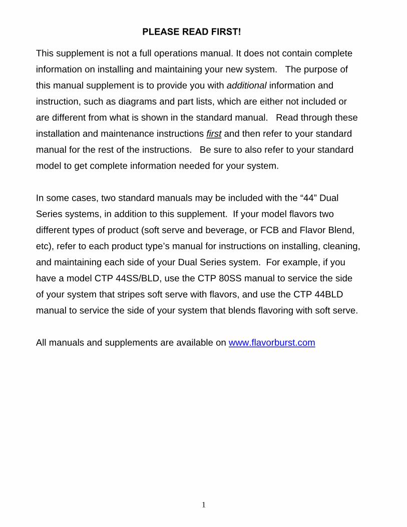
Cabinet
6-1
6-2
OR
“BEV” & “FCB”SYSTEMS
“SS” & “BLD”SYSTEMS
11
18
2629
15
21
24
7
19
3
17
16 17
10
13
2223
25
35
3227
5
4
33
30
5
4
26002
2
8
5
4
14
34
4
28
31
12
See Figure 7Electronic Parts and Connections
14
OR
OR
OR
44BEV & 44BEV/FCB MODELS
44SS, 44BLD, 44SS/BLD, 44SS/BEV, 44SS/FCB,
44BEV/BLD, & 44BLD/FCB MODELS
9-2
44FCB MODEL9-3
9-1
20-1
20-2
OR“BEV” & “FCB”
SYSTEMS
“SS” & “BLD”SYSTEMS
9-4
44SS/BEV, 44BEV/BLD, 44BLD/FCB,44SS/FCB
& 44BEV/BLDMODELS
Figure 2

15
“SS” Injector Assembly and Related Parts (See Figure 3A)
ITEM PART NO. DESCRIPTION QTY. FUNCTION
A INJ 424TS INJECTOR ASSEMBLY WITH SYRUP LINES, ADAPTER, & BRACKET
2* 1**0***
FOR “SS” SYSTEMS: Injects syrups into the product. *2 for 44SS systems. **1 for 44SS/BLD, 44SS/BEV, & 44SS/FCB systems. ***0 for 44BLD, 44BEV, 44FCB, 44BEV/FCB, 44BLD/FCB, & 44BEV/BLD systems.
1 INJ 422 INJECTOR HEAD ASSEMBLY 1 Connects flavor line to inject syrups into product.
1A RUB 652-RSS SMALLER SYRUP PORT O-RING 1 ea. Provides sealed cavity inside syrup port.
1B RUB 651 INJECTOR HEAD O-RING 2-020 1 ea. Provides a sealed cavity.
1C RUB 660 LARGER SYRUP PORT O-RING 1 ea. Provides sealed cavity inside syrup port.
2 INJ 321 GEAR CARTRIDGE ASSEMBLY 1 Rotates product for even syrup distribution.
3 SYR 932 6' 9-TUBE ASSEMBLY 1 Supplies syrup to Injector Head from pumps.
3A FAS 2051 ROLLED FLANGE EYELET 18 ea. Provides tension in syrup line to affix to line coupler.
3B ROT 510 LINE COUPLER 2 ea. Holds flavor lines in place.
3C RUB 610 BAG CONNECTOR O-RINGS 1 ea.Provides extra tension between tube connectors.
3D ROT 515-A 9-TUBE ASSEMBLY WAVE SPRING 1 ea. Provides tension between tube connectors.
3E INJ 116 LINE COUPLER NUT - BLACK 1 ea. Attaches flavor tubes to flavor manifold.
3F SYR 901 6' 9-TUBE ASSEMBLY TUBES 9 ea. Brings syrup from pump to Injector Head.
3G ROT 511 LINE COUPLER NUT 1 ea.Connects flavor lines to the internal 9-Tube Assembly.
3H RUB 602 9-POS TUBE CONN. GASKET 1 ea. Provides sealed cavity.
4 INJ 117 TUBE CONNECTOR BODY –BLACK 1 Secures flavor line manifold to flavor lines.
5 MIS 3142 FLAVOR LINE DUST CAP – FB 80 1 Covers syrup manifold when not connected.
6 INJ 201A SYRUP MANIFOLD - BLACK 1 Connects flavor line to Injector Head.
7 RUB 601 9-POS DUCKBILL CHECK VALVE 1 Provides sealed cavity and prevents syrup leakage.
8 MIS 3143 SUSPENSION BRACKET ASSEMBLY 1 Secures Injector Assembly to the freezer door.
8A FAS 2107 INJECTOR BRACKET KNOB 1 ea. Secures the two bracket pieces.
8B MIS 3143A SUSPENSION BRACKET PART A 1 ea.Attaches to freezer door bolts to hang Injector Assembly.
8C MIS 3143B SUSPENSION BRACKET PART B 1 ea.Secures Bracket Assembly to Injector Assembly.
8D MIS 3144 NYLON SHOULDER WASHER 1 ea. Allows free horizontal movement for bracket
8E ROT 535 ROTOR BRACKET SPRING WASHER 1 ea.Allows space between hanging and base brackets

16
“SS” Injector Assembly and Related Parts (Continued)
ITEM PART NO. DESCRIPTION QTY. FUNCTION
9 INJ 323TS INJECTOR ASSEMBLY - NO HEAD 1 Powers Injector system.
9A INJ 330TS INJECTOR MOTOR ASSEMBLY 1 ea. Supplies power to Motor which turns gears.
9B INJ 331 INJECTOR GEARBOX ASSEMBLY 1 ea.Gears turn Gear Cartridge for even syrup distribution.
9C FAS 2023 ACCESSORY MOUNTING BRACKET KNOB
1 ea. Secures base Mounting Bracket to Gear Box.
10 ADPT 8750-A CROWN ADAPTER WITH O-RINGS
1 Attaches Injector Assembly to freezer door.
10A RUB 659 TAYLOR ADAPTER O-RING 8750 1 ea.Creates tension to secure adapter to freezer door.
10B ADPT 8750 CROWN ADAPTER WITOUT O-RINGS
1 ea. Attaches Injector Assembly to freezer door.
10C RUB 632 INJECTOR ADAPTER O-RING 1 ea.Creates tension to secure adapter to Injector Head.
11 ADPT 101A INJECTOR ADAPTER W/ O-RINGS 1 Attaches Injector Assembly to freezer door.
11A RUB 642 ADAPTER O-RING 1 ea.Creates tension to secure Adapter to freezer door.
11B RUB 640 FLAT ADAPTER GASKET 1 ea. Provides sealed cavity inside Adapter.
11C ADPT 101 INJECTOR ADAPTER 1 ea. Attaches Injector Assembly to freezer.
11D RUB 632 INJECTOR ADAPTER O-RING 1 ea.Creates tension to secure Adapter to Injector Head.
A
3H
1
3
2
3B3G3E3D3B
3F
1C
1B
9A
9C
3A3A 3C
9B
4 5 6 7
9
10
10A
10B
10C
11
11A
11B
11C
11D
26003A
1A
8
8B
8A
8C
8D
8E
FOR “SS” SYSTEMS
Figure 3A

17
“BLD” Blending Assembly and Related Parts (See Figure 3B) ITEM PART NO. DESCRIPTION QTY. FUNCTION
B INJ 424VBLD FLAVOR BLEND BLENDING ASSEMBLY WITH SYRUP LINES, ADAPTER, & BRACKET
2* 1**0***
FOR “BLD” SYSTEMS: Blends syrups into the product. *2 for 44BLD systems. **1 for 44SS/BLD, 44BLD/FCB, & 44BEV/BLD systems. ***0 for 44SS, 44BEV, 44FCB, 44BEV/FCB, 44SS/FCB, & 44SS/BEV systems.
1 ADPT 101A BLENDING ADAPTER W/ O-RINGS 1 Attaches Blending Assembly to freezer door.
1A RUB 642 ADAPTER O-RING 1 ea.Creates tension to secure Adapter to freezer door.
1B RUB 640 FLAT ADAPTER GASKET 1 ea. Provides sealed cavity inside Adapter.
1C ADPT 101 BLENDING ADAPTER 1 ea. Attaches Blending Assembly to freezer.
1D RUB 632 BLENDING ADAPTER O-RING 1 ea.Creates tension to secure Adapter to Blending Head.
2 INJ 422C BLENDING HEAD ASSEMBLY 1 Connects flavor line to inject syrups into product.
2A RUB 652-RSS SMALLER SYRUP PORT O-RING 1 ea. Provides sealed cavity inside syrup port.
2B RUB 651 BLENDING HEAD O-RING 2-020 1 ea. Provides a sealed cavity.
2C RUB 660 LARGER SYRUP PORT O-RING 1 ea. Provides sealed cavity inside syrup port.
3 INJ 321C GEAR CARTRIDGE ASSEMBLY 1 Rotates product for even syrup distribution.
4 SYR 932 6' 9-TUBE ASSEMBLY 1 Supplies syrup to Blending Head from pumps.
4A FAS 2051 ROLLED FLANGE EYELET 18 ea. Provides tension in syrup line to affix to line coupler.
4B ROT 510 LINE COUPLER 2 ea. Holds flavor lines in place.
4C RUB 610 BAG CONNECTOR O-RINGS 1 ea.Provides extra tension between tube connectors.
4D ROT 515-A 9-TUBE ASSEMBLY WAVE SPRING 1 ea. Provides tension between tube connectors.
4E INJ 116 LINE COUPLER NUT - BLACK 1 ea. Attaches flavor tubes to flavor manifold.
4F SYR 901 6' 9-TUBE ASSEMBLY TUBES 9 ea. Brings syrup from pump to Blending Head.
4G ROT 511 LINE COUPLER NUT 1 ea.Connects flavor lines to the internal 9-Tube Assembly.
4H RUB 602 9-POS TUBE CONN. GASKET 1 ea. Provides sealed cavity.
5 INJ 117 TUBE CONNECTOR BODY –BLACK 1 Secures flavor line manifold to flavor lines.
6 MIS 3142 FLAVOR LINE DUST CAP – FB 80 1 Covers syrup manifold when not connected.
7 INJ 201A SYRUP MANIFOLD - BLACK 1 Connects flavor line to Blending Head.
8 RUB 601 9-POS DUCKBILL CHECK VALVE 1 Provides sealed cavity and prevents syrup leakage.

18
“BLD” Blending Assembly and Related Parts (Continued) ITEM PART NO. DESCRIPTION QTY. FUNCTION
9 MIS 3143 SUSPENSION BRACKET ASSEMBLY 1 Secures Blending Assembly to freezer door.
9A FAS 2107 BLENDING BRACKET KNOB 1 ea. Secures the two bracket pieces.
9B MIS 3143A SUSPENSION BRACKET PART A 1 ea.Attaches to freezer door bolts to hang Blending Assembly.
9C MIS 3143B SUSPENSION BRACKET PART B 1 ea.Secures Bracket Assembly to Blending Assembly.
9D MIS 3144 NYLON SHOULDER WASHER 1 ea. Allows left and right movement for bracket.
9E ROT 535 ROTOR BRACKET SPRING WASHER 1 ea.Allows space between hanging and base brackets.
10 INJ 330-TSC BLENDING MOTOR ASSEMBLY – HIGH RPM
1 Powers Blending system.
11 INJ 331 BLENDING GEARBOX ASSEMBLY 1 Gears turn Gear Cartridge for even syrup distribution.
11A FAS 2023 ACCESSORY MOUNTING BRACKET KNOB
1 ea. Secures base Mounting Bracket to Gear Box.
12 ADPT 8750-A CROWN ADAPTER WITH O-RINGS
1 Attaches Blending Assembly to freezer door.
12A RUB 659 TAYLOR ADAPTER O-RING 8750 1 ea.Creates tension to secure adapter to freezer door.
12B ADPT 8750 CROWN ADAPTER WITOUT O-RINGS
1 ea. Attaches Blending Assembly to freezer door.
12C RUB 632 BLENDING ADAPTER O-RING 1 ea.Creates tension to secure adapter to Blending Head.
FOR “BLD” SYSTEMSB
4H
2
4
3
4B4G4E4D4B
4F
2C
2B
11A
4A4A 4C5 6 7 8
12
12A
12B
12C
1
1A
1B
1C
1D
26003
2A
9
9B
9A
9C
9D
9E
10
11
Figure 3B

19
“BEV” Blending Assembly and Related Parts (See Figure 3C)
ITEM PART NO. DESCRIPTION QTY. FUNCTION
C INJ 424VTS VERTICAL BLENDING ASSEMBLY WITH SYRUP LINES, ADAPTER, & BRACKET
2* 1**0***
FOR “BEV” SYSTEMS: Blends syrups into the product. *2 for 44BEV systems. **1 for 44SS/BEV, 44BEV/BLD, & 44BEV/FCB systems. ***0 for 44BLD, 44SS, 44FCB, 44SS/FCB, 44BLD/FCB, & 44SS/BLD systems.
1 INJ 422 BLENDING HEAD ASSEMBLY 1 ea.Connects flavor line to inject syrups into product.
1A RUB 652-RSS SMALLER SYRUP PORT O-RING 1 ea. Provides sealed cavity inside syrup port.
1B RUB 651 BLENDING HEAD O-RING 2-020 1 ea. Provides a sealed cavity.
1C RUB 660 LARGER SYRUP PORT O-RING 1 ea. Provides sealed cavity inside syrup port.
2 INJ 321S GEAR CARTRIDGE ASSEMBLY – VERTICAL BLENDER
1 Rotates product for even syrup distribution.
3 SYR 932 6' 9-TUBE ASSEMBLY 1 Supplies syrup to Blending Head from pumps.
3A FAS 2051 ROLLED FLANGE EYELET 18 ea. Provides tension in syrup line to affix to line coupler.
3B ROT 510 LINE COUPLER 2 ea. Holds flavor lines in place.
3C RUB 610 BAG CONNECTOR O-RINGS 1 ea.Provides extra tension between tube connectors.
3D ROT 515-A 9-TUBE ASSEMBLY WAVE SPRING 1 ea. Provides tension between tube connectors.
3E INJ 116 LINE COUPLER NUT - BLACK 1 ea. Attaches flavor tubes to flavor manifold.
3F SYR 901 6' 9-TUBE ASSEMBLY TUBES 9 ea. Brings syrup from pump to Blending Head.
3G ROT 511 LINE COUPLER NUT 1 ea.Connects flavor lines to the internal 9-Tube Assembly.
3H RUB 602 9-POS TUBE CONN. GASKET 1 ea. Provides sealed cavity.
4 INJ 117 TUBE CONNECTOR BODY –BLACK 1 Secures flavor line manifold to flavor lines.
5 MIS 3142 FLAVOR LINE DUST CAP – FB 80 1 Covers syrup manifold when not connected.
6 INJ 201A SYRUP MANIFOLD - BLACK 1 Connects flavor line to Blending Head.
7 RUB 601 9-POS DUCKBILL CHECK VALVE 1 Provides sealed cavity and prevents syrup leakage.
8 MIS 3143 BLENDING SUSPENSION BRACKET ASSEMBLY
1 Secures Blending Assembly to the freezer door.
8A FAS 2107 INJECTOR BRACKET KNOB 1 ea. Secures the two bracket pieces.
8B MIS 3143A BLENDING BRACKET PART A 1 ea.Attaches to freezer door bolts to hang Blending Assembly.
8C MIS 3143B BLENDING BRACKET PART B 1 ea.Secures Bracket Assembly to Blending Assembly.

20
“BEV” Blending Assembly and Related Parts (Continued)
ITEM PART NO. DESCRIPTION QTY. FUNCTION
9 INJ 323TS BLENDING ASSEMBLY - NO HEAD 1 Powers Blending system.
9A INJ 330TS BLENDING MOTOR ASSEMBLY 1 ea. Supplies power to Motor which turns gears.
9B INJ 331 BLENDING GEARBOX ASSEMBLY 1 ea.Gears turn Gear Cartridge for even syrup distribution.
9C FAS 2023 ACCESSORY MOUNTING BRACKET KNOB
1 ea. Secures base Mounting Bracket to Gear Box.
10 ADPT 104R-A CROWN ADAPTER WITH O-RINGS
1 Attaches Blending Assembly to freezer door.
10A RUB 627 TAYLOR ADAPTER O-RING 8750 1 ea.Creates tension to secure adapter to freezer door.
10B ADPT 104R CROWN ADAPTER WITOUT O-RINGS
1 ea. Attaches Blending Assembly to freezer door.
10C RUB 632 BLENDING ADAPTER O-RING 1 ea.Creates tension to secure adapter to Blending Head.
C
3H
1
3
2
3B3G3E3D3B
3F
1C
1B
9A
9C
3A3A 3C
9B
4 5 6 7
9
10
10A
10B
10C
26003B
1A
8
8B
8A
8C
8D
8E
FOR “BEV” SYSTEMS
Figure 3C

21
“FCB” Door Spout Assembly and Related Parts (See Figure 3D)
ITEM PART NO. DESCRIPTION QTY. FUNCTION
D ADPT TY80S-FCB
MODIFIED FCB FREEZER SPOUT ASSEMBLY
2* 1**0***
FOR “FBC” SYSTEMS: Dispenses product blended with syrups. *2 for 44FCB systems. **1 for 44SS/FCB, 44BEV/FCB, & 44BLD/FCB systems. ***0 for 44BLD, 44BEV, 44SS, 44BEV/BLD, 44SS/BEV & 44SS/BLD systems.
1 FCB 112 MODIFIED DOOR SPOUT ASSEMBLY
1 Dispenses product mixed with flavorings.
1A RUB 652-RSS SMALLER SYRUP PORT O-RING 1 ea. Provides a sealed cavity inside the syrup port.
1B RUB 660 LARGER SYRUP PORT O-RING 1 ea. Provides a sealed cavity inside the syrup port.
2 ELE 530 SPIGOT SWITCH ASSEMBLY KIT 1 Activates the syrup pumps.
2A MIS 3179 MAGNETIC ACTUATOR PIN 1 ea. Activates the Spigot Switch.
3 FCB 121 FLOW RATE CONTROLLER 1 Regulates the rate at which product is dispensed.
3A FAS 2134 8-32 x 1 ½” M/SCREW P.H. SS 1 ea.Adjusts to shorten and lengthen the assembly to allow more or less product dispensed.
3B FCB 115 8-32 X 1” PLAS STAND OFF 1 ea. Connects the two screws of the assembly.
3C FAS 2024 8-32 X ¼” M/SCREW P.H. SS 1 ea. Remains as a stationary screw.
4 SYR 932 6’ 9-TUBE ASSEMBLY 1 Supplies syrup to the draw spout from the pumps.
4A FAS 2051 ROLLED FLANGE EYELET 18 ea. Provides tension in syrup line to affix to line coupler.
4B ROT 510 LINE COUPLER 2 ea. Holds flavor lines in place.
4C RUB 610 BAG CONNECTOR O-RING 1 ea. Provides extra tension between tube connectors.
4D ROT 515-A 9-TUBE ASSEMBLY WAVE SPRING 1 ea. Provides tension between tube connectors.
4E INJ 116 LINE COUPLER NUT – BLACK 1 ea.Connects flavor lines to the internal 9-Tube Assembly.
4F SYR 901 6’ 9-TUBE ASSEMBLY TUBES 9 ea.Brings syrup from pump to modified door spout.
4G ROT 511 LINE COUPLER NUT 1 ea.Connects the flavor lines to the internal 9-Tube Assembly.
4H RUB 602 9-POS TUBE CONNECTOR GASKET
1 ea. Provides a sealed cavity.
5 INJ 117 TUBE CONNECTOR BODY-BLACK 1 Secures flavor line manifold to flavor lines.
6 MIS 3142 FLAVOR LINE DUST CAP- FB 80 1 Covers syrup manifold when not connected.
7 INJ 201A SYRUP MANIFOLD 1 Connects flavor line to modified door spout.
8 RUB 601 9-POS DUCKBILLE CHECK VALVE 1 Provides sealed cavity and prevents syrup leakage.

22
“FCB” Door Spout Assembly and Related Parts
3A
3B
3C
2A
2
4H
4
4B 4G 4E 4D 4B4F4A 4A4C
56
78
1
3
1B
1A
D FOR “FCB” SYSTEMS26003D
Figure 3D

23
Soft Serve Syrup Pump and Related Parts (See Figure 4A)
ITEM PART NO. DESCRIPTION QTY. FUNCTION
A N/A SOFT SERVE SYRUP PUMP SYSTEM
8* 4** 0***
FOR “SS” & “BLD” SYSTEMS: Pumps syrup from flavor bags into flavor lines. *8 for 44SS, 44BLD, & 44SS/BLD systems. **4 for 44SS/FCB, 44SS/BEV, 44BLD/FCB, & 44BEV/BLD systems. ***0 for 44BEV, 44FCB, & 44BEV/FCB systems.
1 N/A SOFT SERVE SYRUP PUMP 1 Pumps syrup from bags to flavor lines.
1A SYR 307 PERISTALTIC SYRUP PUMP 1 ea. Pumps syrup from bags to flavor lines.
1B TUB 806 1/8” SYRUP PUMP REPL TUBE 1 ea. Transports syrup through pump.
1C FAS 2066 SYRUP PUMP TUBE WASHER-1/4 1 ea. Secures pump tube.
1D FAS 2067 SYRUP PUMP CLAMP-HOSE-1/4" 1 ea. Prevents pump tube from slipping.
1E FAS 2051 ROLLED FLANGE EYELET 1 ea. Creates tension for tighter fit.
1F FIX 1036 1/4" TO 1/4" OD UNION ELBOW 1 ea. Connects syrup in tube to pump.
1G FIX 1035 1/4 TO 3/16 OD REDUCING UNION 1 ea. Connects syrup pump to flavor line out.
2 SYR 944 SYRUP TUBE ASSEMBLY – SOFT SERVE 1 Transports flavor from bag to pump.
2A FIX 1054 1/4” ID HOSE BARB SHUTOFF 1 ea. Connects flavor line to flavor bag.
2B SYR 902 FLAVOR-IN TUBE 1 ea. Carries syrup from syrup bag to pump.
2C TUB 811 TUBE-SILICONE .188X.375 PE FB80 1 ea. Connects barb fitment to tube port.
2D FIX 1048 FITTING-1/4X1/4 BARB FB80 1 ea. Connects syrup tube to silicone tube.
3 SYR 941A SYRUP BAG ADAPTER 1 Connects bag fitment to flavor lines.
3A SYR 940 SYRUP BAG ADAPTER CAP 1 ea. Attaches to flavor bag fitment.
3B SYR 939B SYRUP BAG ADAPTER VALVE 1 ea. Transports syrup to quick connect fitment.
3C RUB 662 SYRUP BAG ADAPTER O-RING 1 ea. Provides sealed cavity for Adapter.
4 SYR 946 SYRUP BAG LOCK 1 Secures the syrup bag fitments to the tray.
5 ELE 932-MX PUMP HARNESS CABLE - MX 1 Powers the syrup and sanitizer pumps.

24
Soft Serve Syrup Pump and Related Parts
26004A
3
4
3A 3B
3
3C
1
1D1G
1A
1C1B
1E
1F
A
2
2A 2C2D
2B
Figure 4A

25
Beverage Syrup Pump and Related Parts (See Figure 4B) ITEM PART NO. DESCRIPTION QTY. FUNCTION
B N/A BEVERAGE SYRUP PUMP SYSTEM
8* 4** 0***
FOR “BEV” & “FCB” SYSTEMS: Pumps syrup from flavor bags to flavor lines. *8 for 44BEV, 44FCB, & 44BEV/FCB systems. **4 for 44SS/FCB, 44SS/BEV, 44BLD/FCB, & 44BEV/BLD systems. ***0 for 44SS, 44BLD, & 44SS/BLD systems
1 N/A SHAKE SYRUP PUMP 1 ea. Pumps syrup from bags to flavor lines.
1A SYR 926 PERISTALTIC SYRUP PUMP 1 ea. Pumps syrup from bags into flavor lines.
1B TUB 809 1/4" SYRUP SHAKE PUMP REPLACEMENT TUBE
1 ea. Transports syrup through pump.
1C FIX 1045 1/4" TUBE TO 1/4" HOSE STEM 1 ea. Creates tension for tighter fit, connects pump to fitment.
1D FIX 1035 1/4 TO 3/16 OD REDUCING UNION 1 ea. Connects syrup pump to flavor line out.
1E FIX 1036 1/4" TO 1/4" OD UNION ELBOW 1 ea. Connects bag connector assembly to flavor line/pump.
2 SYR 944SH SYRUP TUBE ASSEMBLY – SHAKE BAG COUPLER
1 ea. Transports the flavoring from the syrup bag to the syrup pump.
2A SYR 928 #27-1102-99 .265" BAG COUPLER 1 ea. Fastens bag fitment to bag connector.
2B TUB 811 TUBE-SILICONE .188X.375 PE FB80 1 ea. Provides sealed cavity inside bag fitment.
2C FIX 1048 FITTING ¼ X ¼ BARB FB80 1 ea. Connects bag coupler assembly to flavor line/pump.
2D SYR 902 FLAVOR-IN TUBE 1 ea. Carries syrup from syrup bag to pump.
3 ELE 932-MX PUMP HARNESS CABLE - MX 1 Powers the syrup and sanitizer pumps.

26
Beverage Syrup Pump and Related Parts
26004B
1
1D
1A
1C1B
1E
B
2
2B2C
2D2A
3
Figure 4B

27
Sanitizer Pump and Related Parts (See Figure 5)
ITEM PART NO. DESCRIPTION QTY. FUNCTION
1-1 MIS 3028-80 FLUSH TUBE ASSEMBLY – SOFT SERVE
1* 0**
FOR “SS” & “BLD” SYSTEMS: Connects with flavor line to flush with sanitizer solution. *1 for 44SS, 44BLD, 44SS/BLD, 44SS/BEV, 44SS/FCB, 44BEV/BLD, & 44BLD/FCB models. **0 for 44BEV, 44FCB, 44BEV/FCB models.
1A FIX 1054 FLAVOR LINE FLUSH FITMENT 1 ea. Connects to flavor in tube.
1B FIX 1051 SANITIZER TANK FITMENT 1 ea. Connects flush tube to Sanitizer Tank.
1C SYR 931 CLEAR TUBING 3 ea. Transports sanitizer to sanitizer / flush tubes.
1D FIX 1046 FLUSH TUBE " Y " CONNECTOR 1 ea. Splits sanitizer flush tube into two tubes.
OR…
1-2 MIS 3028-S FLUSH TUBE ASSEMBLY - SHAKE
1* 0**
FOR 44BEV & 44BEV/FCB MODELS: Connects with flavor line to flush with sanitizer solution. *1 for 44BEV and 44BEV/FCB models. **0 for all other models.
OR…
1-3 N/A FLUSH TUBE ASSEMBLY – FCB BASE
1* 0**
FOR 44FCB MODEL: Connects with flavor line to flush with sanitizer solution. *1 for 44FCB model. **0 for all other models.
1-2 MIS 3028S SANITIZER FLUSH TUBE ASSEMBLY – BEVERAGE
1 ea. Flushes flavor lines with sanitizer.
1E FIX 1023 3/16" X 3/16" BARB TUBE CONNECT
1 ea. Splices together flush tubes.
1F SYR 931 CLEAR TUBING 1 ea. Transports sanitizer to sanitizer / flush tubes.
1G FIX 1045 1/4" TUBE TO 1/4" HOSE STEM 1 ea.Connects pump flush adapter line to sanitizer tank line.
OR…
1-4 MIS 3028S-X PUMP FLUSH ADAPTER EXTENSION
1* 0**
FOR SYSTEMS WITH BOTH SOFT-SERVE AND BEVERAGE / FCB COMPONENTS: Connects with flavor line to flush with sanitizer solution. *1 for 44SS/BEV, 44SS/FCB, 44BLD/FCB, & 44BEV/BLD models. **0 for 44SS, 44BLD, 44SS/BLD, 44BEV, 44FCB, & 44BEV/FCB models.
1-2 MIS 3028S SANITIZER FLUSH TUBE ASSEMBLY – BEVERAGE
1 ea. Flushes flavor lines with sanitizer when attached.
1B FIX 1051 SANITIZER TANK FITMENT 1 ea. Connects flush tube to flush tube connector.
2 TUB 807 SANITIZER TUBE REPLACEMENT
1 Transports sanitizer through pump.
3 SAN 748 SANITIZER PUMP ASSEMBLY 1 Supplies sanitizer to flush tube.
4 FIX 1035 1/4 TO 3/16 OD REDUCING UNION
1 Connects pump to the 9-Tube Assembly.
5 FIX 1023 3/16" X 3/16" BARB TUBE CONNECT
1 0*
Splices together flush tubes. *0 for 44FCB model
6 FIX 1042 TUBE-TO-TUBE ELBOW 3 2*
Connects pump tube to reducing union. *2 with 44FCB model

28
Sanitizer Pump and Related Parts (Continued)
ITEM PART NO. DESCRIPTION QTY. FUNCTION
7 FIX 1053 SANITIZER PUMP T CONNECTOR 1 0*
Splits the connection. *1 with 44FCB model
8 TUB 803 0.17 x 1/4 LDPE TUBING 1 Transports sanitizer from the tank the pump.
9 SYR 931 CLEAR TUBING 1 0*
Transports sanitizer to sanitizer / flush tubes.*0 with 44FCB model
10 FIX 1033 1/4" X 1/4" BLKHD (PUSH-TO-CONNECT) 1 Connects Sanitizer Tank tube to the unit.
11 SYR 900 4' 9-TUBE ASSEMBLY TUBES 3 Transports sanitizer from pump to Diverter Valve.
12 VAL 210 MX SERIES VALVE ASSEMBLY 1 Splits and diverts sanitizer from pump to each 9-Tube Lead
12A VAL 209 MX SERIES DIVERTER VALVE 1 ea.Splits and diverts sanitizer from pump to active syrup line.
12B FIX 1032 3/16” X 1/8” NPTF (PUSH-TO-CONNECT) 3 ea. Connects flavor lines to diverter valve.
13 ELE 932-MX PUMP HARNESS CABLE - MX 1 Powers the syrup and sanitizer pumps.
26005
1C
1C
1D
1-1 1-2 OR1-4
OROR
3
2
10
8
7
1G
1F
1E
1-3
5
1C
1A1B
6
611
4
9
6
1B
1-2
TO SANTIZER TANK
44BEV & 44BEV/FCB
MODELS
44SS, 44BLD, 44SS/BLD, 44SS/BEV, 44SS/FCB, 44BEV/BLD,
& 44BLD/FCB MODELS
44SS/BEV, 44BLD/FCB,44SS/FCB, &
44BEV/BLDMODELS
44FCB MODEL
12B
12A
12B
12B
13
TO 9-TUBE LEAD
TO 9-TUBE LEAD
12
Figure 5

29
Syrup Tray, Sanitizer Tank, 9-Tube Assembly Leads, and Casing (See Figure 6)
ITEM PART NO. DESCRIPTION QTY. FUNCTION
1 SYR 938 MX SERIES INTERNAL 9-TUBE ASSEMBLY
1 Transports syrup from bags to flavor 9-Tube Assembly.
1A SYR 900 4' 9-TUBE ASSEMBLY TUBES 11 ea.Transports syrup and sanitizer from pumps to Injector Assembly.
1B ROT 511 LINE COUPLER NUT 2 ea. Connects flavor lines to the internal 9-Tube Assembly.
1C ROT 512 TUBE CONNECTOR BODY 2 ea. Connects internal 9-Tube Assembly to flavor lines.
1D ROT 510 LINE COUPLER 2 ea Holds flavor lines in place.
1E FAS 2051 ROLLED FLANGE EYELET 18 ea.Creates tension for tighter fit 1 per pump, 9 per tube assembly.
1F MIS 3023 DUST CAP 2 ea. Cover to protect end of flavor lines.
2 SYR 935 4’ 9-TUBE ASSEMBLY EXTENSION
1 Adds length to the flavor line assembly.
2A SYR 900 4' 9-TUBE ASSEMBLY TUBES 9 ea. Transports syrup and sanitizer from pumps to Injector Assembly.
2B ROT 511 LINE COUPLER NUT 2 ea. Connects flavor lines to the internal 9-Tube Assembly.
2C ROT 512 TUBE CONNECTOR BODY 2 ea. Connects internal 9-Tube Assembly to flavor lines.
2D ROT 510 LINE COUPLER 2 ea Holds flavor lines in place.
2E FAS 2051 ROLLED FLANGE EYELET 18 ea.Creates tension for tighter fit 1 per pump, 9 per tube assembly.
2F MIS 3023 DUST CAP 2 ea. Cover to protect end of flavor lines.
3 FIX 1036 1/4" TO 1/4" OD UNION ELBOW 1 Connects sanitizer tube to supply tube.
4 SAN 715 SUPPLY TUBE CAP 1 Fastens grommet securely to tank.
5 RUB 615 FEEDER TUBE RUBBER GROMMET
1 Holds sanitizer tube in place and seals tank hole.
6 SYR 902 SANITIZER SUPPLY TUBING 1 Supplies sanitizer from Sanitizer Tank.
7 SAN 734 HAND PUMP ASSEMBLY-FLUTED TANK
1 Seals Sanitizer Tank and adds pressure when needed.
8 SAN 701 SANITIZER TANK 1 Holds sanitizer solution.
9 MIS 3196 STAINLESS 9-TUBE CASING ASSEMBLY
2 Protects and holds the cables and tubes in place on the freezer side panel.
9A MIS 3190 STAINLESS 9-TUBE CASING HINGED CHANNEL
1 ea. Covers and protects the cables and tubes of the Casing Assembly.
9B MIS 3051 CH-6 CHANNEL MAGNET ASSEMBLY
2 ea. Holds the Casing Channel to freezer panel.
9C FAS 2040 6-32 x 1/4 PAN HEAD SCREW 1 ea. Secures cover to mounting brackets.
9D FAS 2024 8-32 x 1/4 PAN HEAD SCREW 4 ea. Secures magnet assembly to brackets.
9E FAS 2035 8-32 NUTS – EXT. LOCK WASHER 4 ea. Secures magnet assembly to brackets.
10 CAB 113 FLAVORING TRAY 8 Houses syrup bags.
11 TUB 803 .17 x 1/4 LDPE TUBING-PER FOOT 1 Transports sanitizer solution from tank to sanitizer pump.

30
Syrup Tray, Sanitizer Tank, 9-Tube Assembly Leads, and Casing
26009
Sanitizer Tank Assembly is
much larger in scale than shown here
5
4
3
11
6
7
8
To Sanitizer Pump and
Pump Flush Adapter
10
9C
9A
9D
9E9B
9
2B 2B2C 2C2D 2D 2F2F
2E
2E2A
1B 1C 1D 1F1E
A
B 1A
2
1
Figure 6
31
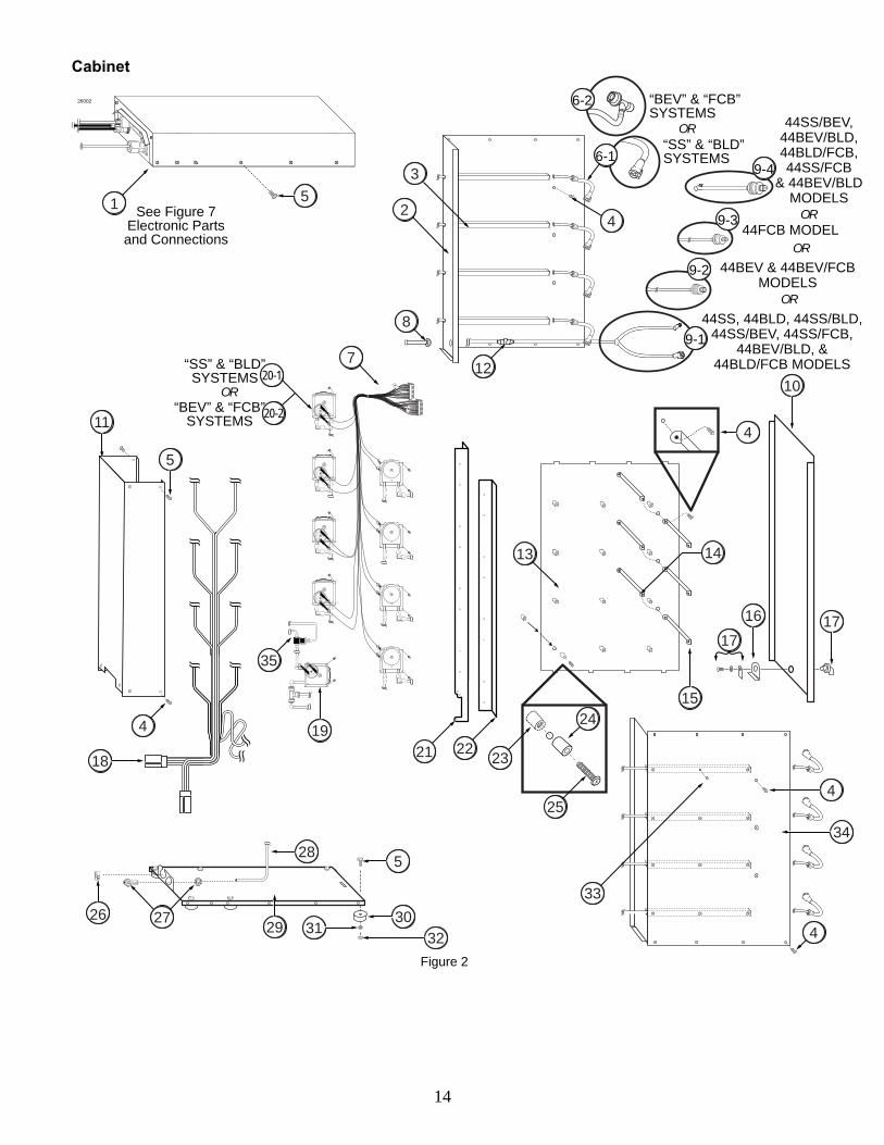
Electronic Parts and Connections (See Figure 7) ITEM PART NO. DESCRIPTION QTY. FUNCTION
1 ELE 905 FLAVOR 10 COLOR TOUCH PANEL 1 Control system for the unit.
2 MIS 3214 TOUCH PANEL MOUNTING BRACKET ASSEMBLY
1* 0**
FOR “SS” & “BLD” SYSTEMS: Secures the Touch Panel to the freezer. *1 for 44SS, 44BLD, 44SS/BLD, 44SS/BEV, 44SS/FCB, 44BLD/FCB, & 44BEV/BLD systems. **0 for 44BEV, 44FCB, & 44BEV/FCB systems.
2A MIS 3214A TOUCH PANEL MOUNTING PLATE 1 ea.Attaches the Touch Panel to the anchor bracket.
2B MIS 3214B MOUNTING ANCHOR BRACKET 1 ea. Allows the bracket to be angled up or down.
2C MIS 3214C MOUNTING BASE PLATE 1 ea.Creates a mounting base for the bracket assembly.
2D FAS 2170 M4 X 8 PHILLIPS SCREW 4 ea.Secures the mounting plate to the Touch Panel.
2E FAS 2174 1/4 - 20 NYLON LOCK NUT S.S. 2 ea.Secures the anchor bracket in a fixed position.
2F MIS 3076 ADHESIVE PAD 1 ea. Secures the mounting bracket to the freezer.
2G FAS 2172 1/4-20 X 1/2 HEX BOLT 2 ea.Hinges the Touch Panel plate and anchor bracket.
2H FAS 2023 MOUNTING BRACKET KNOB 4 ea.Secures the anchor bracket to the base plate.
2I FAS 2171 M4 LOCK WASHER 4 ea.Secures the connection between screw and plate.
2J FAS 2173 FLAT WASHER 18-8 S.S. 2 ea.Secures the connection between bolt and nut.
3 MIS 3220 TOUCH PANEL SIDE MOUNTING BRACKET ASSEMBLY
1* 0**
FOR “BEV” & “FCB” SYSTEMS: Secures the Touch Panel to the freezer. *1 for 44BEV, 44FCB, 44BEV/FCB, 44SS/BEV, 44SS/FCB, 44BLD/FCB, & 44BEV/BLD systems. **0 for 44SS, 44BLD, & 44SS/BLD systems.
3A MIS 3220A TOUCH PANEL MOUNTING PLATE 1 ea.Attaches the Touch Panel to the anchor bracket.
3B MIS 3220B MOUNTING ANCHOR BRACKET 1 ea. Allows the bracket to be angled up or down.
3C MIS 3220C MOUNTING BASE PLATE 1 ea.Creates a mounting base for the bracket assembly.
3D FAS 2170 M4 X 8 PHILLIPS SCREW 4 ea.Secures the mounting plate to the Touch Panel.
3E FAS 2022 1/2" SELF-DRILL SCREW 4 ea.Secures the anchor bracket in a fixed position.
3F FAS 2177 10-32 LOCK NUT 5 ea. Secures the mounting bracket to the freezer.
3G FAS 2171 M4 LOCK WASHER 4 ea.Hinges the Touch Panel plate and anchor bracket.
3H FAS 2178 WASHER #10 2 ea.Secures the anchor bracket to the base plate.
3I FAS 2058 LOCK WASHER 2 ea.Secures the connection between screw and plate.

32
Electronic Parts and Connections (Continued) ITEM PART NO. DESCRIPTION QTY. FUNCTION
4 ELE 924 WIRELESS SPIGOT SWITCH 2* 1** 0***
FOR “SS” & “BLD” SYSTEMS: Sends a wireless signal to the Touch Panel when the freezer draw handle is activated. *2 for 44SS & 44BLD systems. *1 for 44SS/BLD, 44SS/BEV, 44SS/FCB, 44BLD/FCB, & 44BEV/BLD systems. ***0 for 44BEV, 44FCB, & 44BEV/FCB systems.
5 ELE 530 FCB SPIGOT SWITCH ASSEMBLY KIT2* 1** 0***
FOR “FCB” SYSTEMS: Activates the syrup pumps when draw handle is activated. *2 for 44FCB systems. *1 for 44SS/FCB, 44BEV/FCB, & 44BLD/FCB systems. ***0 for 44SS, 44BEV, 44BLD, 44SS/BLD, 44SS/BEV & 44BEV/BLD systems.
5A MIS 3179 FCB MAGNETIC ACTUATOR PIN 1 ea. Activates the Spigot Switch.
6 ELE 525M MALE TO MALE 48” SWITCH EXTENSION
2 Connects Touch Panel to the freezer switch.
7 FAS 2014 8-32 X 1/2" PAN HEAD 16 Secures various parts within the top of unit.
8 MIS 3150 FLAVOR BURST LOGO DECALS 1 Displays Flavor Burst trademark logo.
9 CAB 156 CONNECTOR SHIELD 1 Protects power cables from liquids.
10 ELE 485CTP 120V POWER ENTRANCE MODULE 1 Provides a power connection to the outside of the cabinet.
11 ELE 932-MX PUMP HARNESS CABLE - MX 1 Provides power to syrup & sanitizer pumps.
12 ELE 933 POWER SUPPLY JUMPER CABLE 1 Connects the power supply to the electronics board.
13 ELE 931 EXTERNAL ROTOR CABLE 2* 1** 0***
FOR “SS”, “BLD” & “BEV” SYSTEMS: Connects the drive motor to the back of the cabinet. *2 for 44SS, 44BLD, 44BEV, 44SS/BLD, 44BEV/BLD, & 44SS/BEV systems. **1 for 44BLD/FCB, 44SS/FCB, & 44BEV/FCB systems. ***0 for 44FCB systems.
14-1 INJ 330TS INJECTOR MOTOR ASSEMBLY 2* 1** 0***
FOR “SS” & “BEV” SYSTEMS: Supplies power to Motor which turns gears. *2 for 44SS, 44BEV, & 44SS/BEV systems. **1 for 44SS/BLD, 44BEV/BLD, 44SS/FCB, & 44BEV/FCB systems. ***0 for 44BLD, 44FCB, & 44BLD/FCB systems.
OR…
14-2 INJ 330-TSC BLENDING MOTOR ASSEMBLY FOR “BLD” SYSTEM – HIGH RPM
2* 1** 0***
FOR “BLD” SYSTEMS: Supplies power to Motor which turns gears. *2 for 44BLD systems. **1 for 44SS/BLD, 44BLD/FCB, & 44BEV/BLD systems. ***0 for 44SS, 44BEV, 44FCB, 44BEV/FCB, 44SS/FCB, & 44SS/BEV systems.

33
Electronic Parts and Connections (Continued)
ITEM PART NO. DESCRIPTION QTY. FUNCTION
15 ELE 911 ELECTRONICS BOARD 1 Provides power to the system.
16 FAS 2024 8-32 X 1/4 PAN HEAD SCREW 3 Secures power supply to the base panel.
17 FAS 2035 8-32 NUTS - EXT. LOCK WASHER 8 Secures Electronics Board to the Box and the Electronics Box to the cabinet.
18 FAS 2175 M3.5 NUT - EXT. LOCK WASHER 1 Secures the power entrance module ground wire to the board.
19 ELE 930 INTERNAL ROTOR CABLE 2* 1** 0***
FOR “SS”, “BLD” & “BEV” SYSTEMS: Connects the external rotor cable to the electronics board. *2 for 44SS, 44BLD, 44BEV, 44SS/BLD, 44BEV/BLD, & 44SS/BEV systems. **1 for 44BLD/FCB, 44SS/FCB, & 44BEV/FCB systems. ***0 for 44FCB systems.
20 FAS 2008 4-40 X 3/8" PAN HEAD SCREW 4 Attaches the ethernet plate to the panel.
21 MIS 3216 CLOSURE PLUG 5/8 INCH 1* 2** 3***
Closes up extra opening in the base panel. *1 for 44SS, 44BLD, 44BEV, 44SS/BLD, 44BEV/BLD, & 44SS/BEV systems. **2 for 44BLD/FCB, 44SS/FCB, & 44BEV/FCB systems. ***3 for 44FCB systems.
22 ELE 434 POWER CABLE 1 Supplies the electronics board with power.
23 ELE 927 RJ45 ETHERNET CABLE GLAND 1 Secures the Ethernet cable to the cabinet.
24 ELE 925 RJ45 EHTERNET CABLE - EXTERNAL 1 Connects the Touch Panel to the cabinet.
25 ELE 926 RJ45 ETHERNET CABLE - INTERNAL 1 Connects the Ethernet cable to the electronics board.
26 CAB 138TS ELECTRONICS BASE PANEL 1 Secures electronics board.
27 FAS 2042 4/40 LOCK NUT 4 Secures the Ethernet plate and screws.
28 MIS 3004 CTP ETHERNET CABLE PLATE 1 Converts the touchscreen cable hole to an ethernet cable hole.
29 MIS 3026S TOUCH PANEL CABLE CASING 1 Conceals and protects the Touch Panel cable, as well as attaches it to the freezer.
30 CAB 137-A ELECTRONICS COVER 1 Protects and covers electronics microprocessor.
31 ELE 525 36” SPIGOT SWITCH EXTENSION 1 Adds length to the spigot switch.

34
Electronic Parts and Connections
5A
5
18
12
7
9
8
17
30
31
6
7
14-2
14-1
16
23
19
1121
2524
7
15
26
4
13
22
29
10
20 28 27
33E
3E
3C
3C
3G
3A
3F
3H
3F
3F
3B
3I
“BLD”SYSTEMS
“SS” & “BEV”SYSTEMS
OR
2
2C
2A
2F
2B
2G
2G
2H
2J
2E
2I
2D 1
Figure 7

35
“SS” Spare Parts Kit (See Figure 8A) ITEM PART NO. DESCRIPTION QTY. FUNCTION
A SPR 5800A SPARE PARTS KIT – SOFT SERVE 1* 0**
FOR “SS” SYSTEMS: Houses extra spare parts and wear items. *1 for 44SS, 44SS/BLD, 44SS/FCB, & 44SS/BEV systems. **0 for 44BLD, 44BEV, 44FCB, 44BLD/FCB, 44BEV/BLD, & 44BEV/FCB systems.
1 CW 137 DRIVE MOTOR GEAR 1 Turns gear box gears, powered by the motor.
2 INJ 321 GEAR CARTRIDGE 1 Rotates product for even syrup distribution.
3 RUB 601 9-POS DUCKBILL CHECK VALVE 1 Provides sealed cavity and prevents leakage.
4 RUB 632 LOWER ADAPTER O-RING 1 Creates tension to secure Adapter to Injector Head.
5 RUB 640 FLAT ADAPTER GASKET FOR ADPT 101A ADAPTER
1 Provides sealed cavity inside Adapter.
6 RUB 642 UPPER ADAPTER O-RING FOR ADPT 101A ADAPTER
1 Creates tension to secure Adapter to freezer door.
7 RUB 602 9-POS TUBE CONN. GASKET 1 Provides sealed cavity.
8 RUB 652-RSS SMALLER SYRUP PORT O-RING 1 Provides sealed cavity inside syrup port.
9 RUB 651 INJECTOR HEAD O-RING 2-020 1 Provides a sealed cavity.
10 INJ 201A SYRUP MANIFOLD - BLACK 1 Connects flavor line to Injector Head.
11 ELE 430-RE-1 SPIGOT SWITCH 1 Activates Injector Assembly.
12 INJ 117 TUBE CONNECTOR BODY -BLACK 1 Secures Syrup Line Manifold to flavor lines.
13 ELE 444 1 AMP, 1 1/4" SLOW BLOW FUSE 2 System overload protection.
14 RUB 659 UPPER ADAPTER O-RING FOR ADPT 8750-A ADAPTER
1 Creates tension to secure Adapter to freezer door.
15 RUB 660 LARGER SYRUP PORT O-RING 1 Provides sealed cavity inside syrup port.
26007A
101213
2
6
5
11
7
1
3
4
14
9
15
8
A FOR “SS” SYSTEMS
Figure 8A

36
“BLD” Spare Parts Kit (See Figure 8B) ITEM PART NO. DESCRIPTION QTY. FUNCTION
B SPR 5800BLD SPARE PARTS KIT – SOFT SERVE BLEND
1* 0**
FOR “BLD” SYSTEMS: Houses extra spare parts and wear items. *1 for 44BLD, 44SS/BLD, 44BLD/FCB, & 44BEV/BLD systems. **0 for 44SS, 44BEV, 44FCB, 44SS/FCB, 44SS/BEV, & 44BEV/FCB systems.
1 CW 137 DRIVE MOTOR GEAR 1 Turns the gear box gears, powered by the drive motor.
2 INJ 321C GEAR CARTRIDGE 1 Rotates product for even syrup distribution.
3 RUB 601 9-POS DUCKBILL CHECK VALVE 1 Provides sealed cavity and prevents syrup leakage.
4 RUB 632 LOWER ADAPTER O-RING 1 Creates tension to secure Adapter to Blending Head.
5 RUB 640 FLAT ADAPTER GASKET FOR ADPT 101A ADAPTER
1 Provides sealed cavity inside Adapter.
6 RUB 642 UPPER ADAPTER O-RING FOR ADPT 101A ADAPTER
1 Creates tension to secure Adapter to freezer door.
7 RUB 602 9-POS TUBE CONN. GASKET 1 Provides sealed cavity.
8 RUB 652-RSS SMALLER SYRUP PORT O-RING 1 Provides sealed cavity inside syrup port.
9 RUB 651 BLENDING HEAD O-RING 2-020 1 Provides a sealed cavity.
10 INJ 201A SYRUP MANIFOLD - BLACK 1 Connects flavor line to Blending Head.
11 ELE 430-RE-1 SPIGOT SWITCH 1 Activates Blending Assembly.
12 INJ 117 TUBE CONNECTOR BODY -BLACK 1 Secures Syrup Line Manifold to flavor lines.
13 ELE 444 1 AMP, 1 1/4" SLOW BLOW FUSE 2 System overload protection.
14 RUB 659 UPPER ADAPTER O-RING FOR ADPT 8750-A ADAPTER
1 Creates tension to secure Adapter to freezer door.
15 RUB 660 LARGER SYRUP PORT O-RING 1 Provides sealed cavity inside syrup port.
26007B
B
101213
2
6
5
11
7
1
3
4
14
9
15
8
FOR “BLD” SYSTEMS
Figure 8B

37
“BEV” Spare Parts Kit (See Figure 8C)
ITEM PART NO. DESCRIPTION QTY. FUNCTION
C SPR 5800BEV SPARE PARTS KIT – TOUCHSCREEN BEVERAGE
1* 0**
FOR “BEV” SYSTEMS: Houses extra spare parts and wear items. *1 for 44BEV, 44SS/BEV, 44BEV/BLD, & 44BEV/FCB systems. **0 for 44SS, 44BLD, 44FCB, 44SS/FCB, 44SS/BLD, & 44BLD/FCB systems.
1 ELE 444 1 AMP, 1 1/4" SLOW BLOW FUSE 2 System overload protection.
2 MIS 3076 ADHESIVE PAD 3 Provided to attach switch to freezer or mount brackets.
3 MIS 3113 PANEL SWITCH MOUNTING ARM 1 Bracket to mount spigot switch.
4 RUB 601 9-POS DUCKBILL CHECK VALVE 1 Provides sealed cavity & prevents leakage.
5 INJ 117 TUBE CONNECTOR BODY -BLACK 1 Secures flavor line manifold to flavor lines.
6 RUB 632 LOWER ADAPTER O-RING 1 Creates tension to secure adapter to blending head.
7 RUB 627 UPPER ADAPTER O-RING - FOR ADPT 104R-A
1 Creates tension to secure adapter to freezer door.
8 RUB 602 9-POS TUBE CONN. GASKET 1 Provides sealed cavity.
9 INJ 201A SYRUP MANIFOLD 1 Connects flavor line to blending head.
10 MIS 3112 PANEL SWITCH MOUNTING BRKT 1 Bracket to mount spigot switch.
11 FAS 2043 INTERNAL TOOTH LOCK WASHER 1 Locks brackets into place with screw.
12 FAS 2024 8-32 X 1/4 PAN HEAD 1 Fastens switch brackets together.
13 ELE 510-S SPIGOT SWITCH 1 Activates Blending Assembly.
14 INJ 321S GEAR CARTRIDGE ASSEMBLY – VERTICAL BLENDER
1 Provides sealed cavity inside syrup port.
15 RUB 651 INJECTOR HEAD O-RING 2-020 1 Provides a sealed cavity.
16 RUB 660 LARGER SYRUP PORT O-RING 1 Provides sealed cavity inside syrup port.
17 RUB 652-RSS SMALLER SYRUP PORT O-RING 1 Provides sealed cavity inside syrup port.
18 CW 137 DRIVE MOTOR GEAR 1 Turns gear box gears, powered by motor.
26007C
C
91315 14
2
1
10
7
8
5
43
1112
6
16
18
17
FOR “BEV” SYSTEMS
Figure 8C

38
“FCB” Spare Parts Kit (See Figure 8D)
ITEM PART NO. DESCRIPTION QTY. FUNCTION
D SPR 5800FCB SPARE PARTS KIT FOR FCB 1* 0**
FOR “FCB” SYSTEMS: Houses extra spare parts and wear items. *1 for 44FCB, 44SS/FCB, 44BLD/FCB, & 44BEV/FCB systems. **0 for 44SS, 44BEV, 44BLD, 44SS/BLD, 44SS/BEV, & 44BEV/BLD systems.
1 ELE 444 1 AMP, 1 1/4" SLOW BLOW FUSE 2 System overload protection.
2 MIS 3179 MAGNETIC ACTUATOR PIN 1 Activates the ELE 530 Spigot Switch. Not used with the FB 80FCB Auto Draw Valve system.
3 RUB 601 9-POS DUCKBILL CHECK VALVE 1 Provides sealed cavity and prevents syrup leakage.
4 RUB 660 LARGER SYRUP PORT O-RING 1 Provides a sealed cavity inside the syrup port.
5 RUB 652-RSS SMALLER SYRUP PORT O-RING 1 Provides a sealed cavity inside the syrup port.
6 INJ 117 TUBE CONNECTOR BODY -BLACK 1 Secures flavor line manifold to flavor lines.
7 RUB 602 9-POS TUBE CONN. GASKET 1 Provides sealed cavity.
8 INJ 201A SYRUP MANIFOLD 1 Connects flavor line to the door spout.
26007D
D
RUB 601
RUB 660
RUB 652-RSS
INJ 201A
RUB 602
Kit includes 1 qty of each part displayed -- REORDER EACH SPARE PART IMMEDIATELY UPON VACANCY. REV102908
SPR 5800FCBSPARE PARTS KIT
FOR FB 80FCB BASED SYSTEMS
MIS 3179For use with
ELE 530 SwitchELE 444(2 qty total)
INJ 117TO ORDER, CONTACT YOUR LOCAL DISTRIBUTOR...
Phone:
8 61 2
573
4
FOR “FCB” SYSTEMS
Figure 8D

39
PAGE INTENTIONALLY LEFT BLANK

40
DAILY OPENING, DAILY CLOSING, SCHEDULED MAINTENANCE - NOTES
NOTE: YOUR HANDS SHOULD BE CLEANED AND SANITIZED BEFORE YOU PERFORM THE FOLLOWING PROCEDURES. NOTE: THE FOLLOWING PROCEDURES REQUIRE APPROVED, SERVICEABLE AND SANITIZED TOOLS AND BRUSHES. CONTACT YOUR LOCAL DISTRIBUTOR FOR RECOMMENDED SUPPLIES. NOTE: USE AN APPROVED CLEANER AND SANITIZER FOR THE FOLLOWING PROCEDURES. REFER TO MANUFACTURER’S INSTRUCTIONS FOR PROPER PREPARATIONS OF THESE CLEANING AGENTS. NOTE: INSPECT ALL WEAR ITEMS AND REPLACE IF NECESSARY. Daily Opening, Daily Closing, Scheduled Maintenance for Models: CTP 44SS CTP 44BLD CTP 44BEV CTP 44FCB
The models listed above include flavoring assemblies will be identical. When performing Daily Opening, Daily Closing, and Scheduled Maintenance procedures, these assemblies can be cleaned and sanitized together. Since the parts are the same, they can be used interchangeably on both assemblies and installed on either spout. Refer to your standard manual(s) included with this unit for instructions on Daily Opening, Daily Closing, and Scheduled Maintenance procedures for each side of your Dual Series system.
Daily Opening, Daily Closing, Scheduled Maintenance for Models: CTP 44SS/FCB CTP 44BLD/FCB CTP 44BEV/FCB
For models with one side flavoring Frozen Carbonated Beverages, the “FCB” flavoring assembly is very different from the other flavoring assemblies. The parts of this assembly are easily identifiable, and therefore can be cleaned and maintained with another type of flavoring assembly. Refer to your standard manual(s) included with this unit for instructions on Daily Opening, Daily Closing, and Scheduled Maintenance procedures for each side of your Dual Series system. Daily Opening, Daily Closing, Scheduled Maintenance for Models: CTP 44SS/BLD CTP 44SS/BEV CTP 44BEV/BLD
If your Dual Series system flavors two different types of products, your flavoring assemblies may appear identical when they are in fact different. For the models listed above, keep the flavoring assemblies separate when cleaning and sanitizing so that the parts do not get mixed up and assembled with the wrong parts. Also, take note which assembly is installed on which spout, so that the assembly doesn’t get installed on the wrong spout. When in doubt, use the illustrations in the next section and the parts diagrams at the front of this manual supplement. Refer to your standard manual(s) included with this unit for instructions on Daily Opening, Daily Closing, and Scheduled Maintenance procedures for each side of your Dual Series system. Do not mix one assembly’s parts with another’s.

41
Comparing the Injector and Blending Assemblies
26100
There are three different flavoring assemblies associated with the Dual Series models that appear very similar, especially when assembled. Use the illustrations below to determine which part goes with which flavoring assembly.
INJ 424TS - Soft Serve “SS” Injector Assembly
INJ 424BLD - Flavor Blend “BLD” Blending Assembly
INJ 424VTS - Frozen Beverage “BEV” Blending Assembly 1. The difference between the Injector and
Blending Heads is in the number of pins inside the head. The soft serve Injector Head only has one pin. The blend and beverage Blending Heads have 2 pins, one pin being slightly shorter.
“SS” “BLD” & “BEV Soft Serve Flavor Blend Frozen Beverage
INJ 422(1 pin)
INJ 422C & INJ 422VS(2 pins)
(Identical and Interchangeable)26101
NOTE: THE FLAVOR BLEND HEAD AND THE BEVERAGE HEAD ARE IDENTICAL, EVEN THOUGH THEY CURRENTLY HAVE THE SAME PART NUMBER. THESE HEADS WORK WITH BOTH THE INJ 424BLD FLAVORING ASSEMBLY AND THE INJ 424VTS FLAVORING ASSEMBLY.
2. The difference between the three Gear Cartridges is whether or not it has blending vanes and screen, and the type of vanes. The soft serve Gear Cartridge has no blending vanes or screen. The blend Gear Cartridge a screen across the bottom, and the blending vanes are taller with openings that are angled. The beverage Gear Cartridge does not have a screen, the blending vanes are shorter with openings that are horizontal.
INJ 321SINJ 321 INJ 321C
(horizontal vanes)
(no screen)
(angled vanes)
(screen)
(no vanes)
(no screen)
“SS” “BLD” “BEV” Soft Serve Flavor Blend Frozen Beverage
26102 NOTE: THESE GEAR CARTRIDGES ARE SPECIALLY DESIGNED TO MIX THE FLAVORING WITH PRODUCT IN CERTAIN WAYS. BE SURE TO INSTALL THE CORRECT CARTRIDGE WITH ITS ASSEMBLY.

42
3. The difference between the Drive Motors is in the speed of the motor and the direction the motor turns the small white gear at the bottom. Both the soft serve and frozen beverage systems use the same standard speed motor. It has a “UNIVERSAL” label. When activated by the spigot switch, the small gear at the bottom rotates clockwise. The Flavor Blend systems has a higher speed motor that turns the gear counter-clockwise. It has a label that says “High RPM”.
INJ 330-TSC(High Speed)
INJ 330TS(Standard Speed)
(gear spins clockwise) (gear spins counter-clockwise)
“UNIVERSAL” “High RPM”
“SS” & “BEV” “BLD” Soft Serve & Frozen Beverage Flavor Blend
26103 NOTE: TO CHECK THE SPIN DIRECTION OF THE GEAR AT THE BOTTOM OF THE MOTOR, REMOVE IT FROM THE GEAR BOX ASSEMBLY AND CONNECT IT TO THE MOTOR CABLE. ACTIVATE THE SPIGOT SWITCH MANUALLY IF YOU HAVE AN EXTERNAL SWITCH OR BY LIFTING THE DRAW PIN ON THE FREEZER.
4. The soft serve and blend assemblies each come with two spout adapters, which fit most soft serve freezers. The frozen beverage flavoring assembly comes with one adapter that fits most frozen beverage freezers. Other adapters are available from your local distributor.
Each of these three adapters come with a top o-ring, a plastic body and a lower o-ring. The soft serve ADPT 8750-A also comes with a white gasket. The white plastic bodies are each different. The ADPT 8750-A body is the shortest, with a short top band. In comparison, the ADPT 101A is a bit taller, with a taller top band. The frozen beverage ADPT 104R-A is the tallest of the three adapters, with the widest top band.
shortest heightshort top band
medium heighttall top band
tallest heighttall top band
wide top band
“SS” & “BLD” “BEV” Soft Serve & Flavor Blend Frozen Beverage
26104
ADPT 8750-A ADPT 104R-AADPT 101A

43
5. The lower o-rings of all three adapters are all the same – RUB 632. Using this o-ring as a reference to the others, the upper o-ring for the ADPT 8750-A is larger and thicker. The upper o-ring for the ADPT 101A is about the same diameter, but it is thicker than the lower o-ring. The upper o-ring for the beverage 104R-A adapter is larger in diameter, but about the same thickness as the lower o-ring.
shortest heightshort cap medium height tallest height
widest cap
ADPT 8750-A ADPT 104R-A
RUB 632 RUB 632RUB 632
RUB 642RUB 659 RUB 627
whitegasket
ADPT 101A
26105
“SS” & “BLD” “BEV” Soft Serve & Flavor Blend Frozen Beverage
6. The Gear Box, 9-Tube Assembly and
suspension bracket are the same in each of the three flavoring assemblies.

44
NOTE: BE SURE TO PLACE A CONTAINER UNDER THE INJECTOR HEAD TO CATCH THE PRODUCT AND SANITIZER SOLUTION. NOTE: YOUR HANDS SHOULD BE CLEANED AND SANITIZED BEFORE YOU PERFORM THE FOLLOWING PROCEDURE. NOTE: THE FOLLOWING PROCEDURES REQUIRE APPROVED, SERVICEABLE AND SANITIZED TOOLS AND BRUSHES. CONTACT YOUR LOCAL DISTRIBUTOR FOR RECOMMENDED SUPPLIES. NOTE: USE AN APPROVED CLEANER AND SANITIZER FOR THE FOLLOWING PROCEDURES. REFER TO MANUFACTURER’S INSTRUCTIONS FOR PROPER PREPARATIONS OF THESE CLEANING AGENTS. NOTE: INSPECT ALL WEAR ITEMS AND REPLACE IF NECESSARY. Since this system is split between two spouts, it is important that the correct syrups are installed into the correct trays. Follow these steps to determine which flavors should be installed into which trays.
1. Ensure your syrups are connected to the desired spout. Each syrup flavor is stored inside a numbered tray (1-8) within the system cabinet. The syrups in trays 1-4 are stored in the top four spaces in your cabinet. They are typically connected to the first spout in your setup. See that the 9-Tube Assembly Lead “A” at the back of the unit is connected to that spout. Lead “B” carries the syrups from trays 5-8 (bottom four spaces in your cabinet) to your other spout.
1
3
5
7
2
4
6
8
SPOUT1SPOUT2
26110
2. Ensure the correct syrup type is flavoring the correct product type. Check the label of the syrup you are installing in each tray. The soft serve stripe, soft serve blend and frozen beverage syrups are each formulated to work specifically with the product they are mixing with and the Flavor Burst system they are installed in. Color intensity, flavor intensity, and whether or not they blend with the product vary from each type. Therefore, a soft serve striping syrup will not blend, taste or look as well using a Flavor Blend or frozen beverage system. Nor will a frozen beverage syrup or a Flavor Blend syrup hold a clean stripe on soft serve product. Flavor Blend syrups are formulated to blend more evenly and have a stronger flavor to compensate for the thicker soft serve product. Frozen beverage flavors do not need the flavor or color intensity to mix with the thinner frozen beverage products.
REPLACING THE SYRUP FLAVORS - NOTES

45
3. Soft Serve Striping Syrups: There are two different kinds of soft serve syrup. One (Flavor Burst) is formulated to stripe the soft serve and is compatible with the “SS” model systems. The flavor part numbers for these syrups either end in a number or “SEA”. The striping syrup number for Strawberry is FLA 002SEA; Black Cherry is FLA 003.
4. Soft Serve Flavor Blend Syrups: The other soft serve syrup type (Flavor Blend) is formulated to blend with soft serve product and is compatible with the “BLD” model systems. These syrup numbers end in the letters “BLD”. For example, the blend flavor number for Strawberry is FLA 002BLD.
5. Frozen Beverage Syrups: These syrups have a “BEV” suffix to the part numbers, such as FLA 002BEV. Frozen Beverage syrups are compatible with “BEV” model systems and most frozen beverage products. These products include shakes, slushes, frozen carbonated beverages, frozen cocktails, smoothies, and the JavaLatte frozen coffee mix.
6. Once you have determined which syrups to install into which trays, use your standard operations manual to install or replace syrup flavors. Under normal operating conditions, flavors are installed as previous flavors become empty. However, you may change flavors periodically as desired.

46
NOTE: YOUR HANDS SHOULD BE CLEANED AND SANITIZED BEFORE YOU PERFORM THE FOLLOWING PROCEDURES. NOTE: INSPECT ALL WEAR ITEMS AND REPLACE IF NECESSARY. NOTE: THE FOLLOWING PROCEDURES REQUIRE APPROVED, SERVICEABLE AND SANITIZED TOOLS AND BRUSHES. CONTACT YOUR LOCAL DISTRIBUTOR FOR RECOMMENDED SUPPLIES. NOTE: USE AN APPROVED CLEANER AND SANITIZER FOR THE FOLLOWING PROCEDURES. REFER TO MANUFACTURER’S INSTRUCTIONS FOR PROPER PREPARATIONS OF THESE CLEANING AGENTS. NOTE: THE SYSTEM IS NOT TO BE USED BY PERONS (INCLUDING CHILDREN) WITH REDUCED PHYSICAL, SENSORY OR MENTAL CAPABILITIES, OR LACK OF EXPERIENCE AND KNOWLEDGE, UNLESS THEY HAVE BEEN GIVEN SUPERVISION OR INSTRUCTION. NOTE: CHILDREN ARE TO BE SUPERVISED WHEN USING THE SYSTEM AND SHALL NOT PLAY WITH THE SYSTEM. NOTE: INSTALL THE SYSTEM WHERE AMBIENT TEMPERATURES ARE BETWEEN 60 AND 80 DEGREES FAHRENHEIT FOR CORRECT OPERATION. NOTE: INSTALL THE SYSTEM IN A LOCATION WHERE ITS USE AND MAINTENANCE IS RESTRICTED TO TRAINED PERSONNEL.
Installing the Spout Adapters - Notes 1. The soft serve and blend assemblies each
come with two spout adapters, which fit most soft serve freezers. The frozen beverage flavoring assembly comes with one adapter that fits most frozen beverage freezers.
The ADPT 8750-A body is the shortest, with a short top band. In comparison, the ADPT 101A is a bit taller, with a taller top band. The frozen beverage ADPT 104R-A is the tallest of the three adapters, with the widest top band.
shortest heightshort top band
medium heighttall top band
tallest heighttall top band
wide top band
“SS” & “BLD” “BEV” Soft Serve & Flavor Blend Frozen Beverage
26104
ADPT 8750-A ADPT 104R-AADPT 101A
NOTE: OTHER ADAPTERS ARE AVAILABLE FROM YOUR LOCAL DISTRIBUTOR. 2. Install an adapter on each spout according
to instructions in your standard operations manual.
EQUIPMENT SETUP

47
Installing the Touch Panel and Mounting Bracket - Notes The Color Touch Panel is the control unit for the Flavor Burst® system. Normal operating functions are performed using the Touch Panel and the freezer draw handle. 1. Touch Panel Mounting Bracket Options:
Depending on the model of your system, one or two brackets are included with your system. A top-mount bracket is included with systems that connect to two soft serve spouts. A side-mount bracket is included with systems that connect to beverage and FCB. Both brackets are included with systems that attach to one soft serve spout and one beverage or FCB spout.
MIS 3214 MIS 3200
26106
“SS” & “BLD” “BEV” & “FCB” Soft Serve & Flavor Blend Frozen Beverage & FCB
Top-Mount Bracket Side-Mount Bracket
2. Mounting on a Single Freezer with Multiple Spouts: When mounting the bracket on a single freezer with two spouts use the top-mount bracket when possible. Otherwise, mount the panel to the left of the first spout.
MIS 3214
MIS 3200
Single Freezer Side Mount
26107
Single Freezer Top Mount
3. Mounting on Two Separate Freezers: When
the system is attached to two separate freezers, the Color Touch Panel is typically mounted in between the two freezer. If this is not possible, mount the panel on the freezer to the left.
Two Freezer Side Mount
26108
Two Freezer Top Mount
4. Once you have chosen the appropriate
bracket and where it will be mounted, install the Touch Panel and mounting bracket on the freezer according to instructions in your standard operations manual.

48
Installing the Spigot Switches - Notes When connecting two switches on the Color Touch Panel switch ports, it does not matter which port goes with each switch. You will activate and assign each port to spout and switch it’s connected to when you go through the Equipment Setup Wizard program on your Color Touch Panel. These instructions are detailed in the Color Touch Panel manual. If your Dual Series system connects to two soft serve spouts, you will have two wireless switches, labeled “1” and “2”. In the Equipment Setup Wizard, there is an option for each of these wireless switches when assigning them to the spouts. EQUIPMENT SETUP – Continued Continue with the EQUIPMENT SETUP instructions in your standard operations manual(s). For systems flavoring two different product types, refer to each type of manual for setup on that freezer. For example, to install the Spigot Switch on a freezer striping soft serve product, refer to the CTP 80SS manual. For switch setup on an FCB freezer, see the CTP 80FCB manual. Perform the instructions in the following sections of EQUIPMENT SETUP:
Sanitizing the Injector System
Assembling the Injector Assembly
Installing the Injector System and Suspension Bracket
Mounting the Tube / Cable Casing
Assemblies
Installing & Filling the Sanitizer Tank
Connecting the Unit Syrup Lines
The syrup line Lead “A” at the lower back of the cabinet is connected to the 4 bags of syrup in trays #1-4. The syrup line Lead “B” is connected to the remaining bags of syrup in trays #5-8. An additional tube in each Lead connects the Sanitizer Tank to each spout assembly. A 9-Tube Extension is included to connect the Lead that is the furthest from the corresponding spout assembly.
1. Locate the 9-Tube Leads labeled “A” and
“B” at the back of the cabinet. Lead “A” is connected to the first four flavors in your cabinet; Lead “B” connects to the frozen beverage freezer. Determine which Lead will be connected to the freezer furthest away from the cabinet and requires the Extension. If you do not need the Extension (ie, both 9-Tube Assemblies reach to the back of the cabinet), then skip to Step 10.
B
A
B
A
26231
2. Remove the dust cap of the Lead that will require the Extension. Slide the coupler casing toward the unit to expose the Lead line coupler.

49
3. Ensure the 9-hole gasket is placed between the Extension and 9-Tube Lead coupler pins. The gasket must be in place to seal the connection and prevent leakage.
4. Align the coupler pins of the Lead with the coupler pins of the 9-Tube Extension and connect the assemblies.
5. Slide the coupler casing over the connection and screw each coupler nut into each end of the casing. Tighten the coupler nuts to secure the connection.
6. Removed the dust cab from the other end of the 9-Tube Extension. Slide the coupler casing back to expose the Extension coupler.
7. Remove the 9-hole gasket from one of the 9-Tube Assemblies and align the gasket with the coupler pins of the Extension.
8. Align the coupler pins of the 9-Tube Extension with the coupler pins of the appropriate 9-Tube Assembly.
NOTE: ENSURE EACH LEAD IS CONNECTED TO THE CORRECT SPOUT. THE COLOR TOUCH PANEL IS DESIGNED TO OPERATE CERTAIN PUMPS ASSOCIATED WITH EACH LEAD; MIXING THESE LEADS WITH THE WRONG 9-TUBE ASSEMBLIES WILL RESULT IN FLAVORS PUMPING TO THE WRONG FREEZER.

50
9. Slide the coupler casing over the connection and screw each coupler nut into each end of the casing. Tighten the coupler nuts to secure the connection.
10. Remove the dust cap from a 9-Tube Lead not using the Extension. Slide the coupler casing toward the unit to expose the lead line coupler.
11. Remove the 9-hole gasket from the
remaining 9-Tube Assembly and align the gasket with the coupler pins of the Lead.
12. Align the coupler pins of the Lead with the appropriate 9-Tube Assembly coupler pins and connect the assemblies.
1- 4
A-D
26236
NOTE: ENSURE EACH LEAD IS CONNECTED TO THE CORRECT SPOUT. THE COLOR TOUCH PANEL IS DESIGNED TO OPERATE CERTAIN PUMPS ASSOCIATED WITH EACH LEAD; MIXING THESE LEADS WITH THE WRONG 9-TUBE ASSEMBLIES WILL RESULT IN FLAVORS PUMPING TO THE WRONG FREEZER. 13. Slide the coupler casing over the connection
and screw each coupler nut into each end of the casing. Tighten the coupler nuts to secure the connection.
14. If no Extension was used, repeat Steps 10-
13 to connect the other Lead and 9-Tube Assembly.

51
Power Connections and Power Up The electrical connections for the Dual Series system are located on the upper back panel of the unit. Once the cables have been attached and the unit is turned on, the system can remain on during normal operations from day to day. It does not need to be turned off unless it is being serviced or moved, or unless it is not used for a long period of time. The CTP 44FCB system will have no motor cables to connect. A Dual Series system with one side FCB will have only one motor cable to connect. NOTE: ELELCTRICAL HAZARD - DO NOT HANDLE OR OPERATE NEAR WATER. 1. Ensure the power-switch is in the “off”
position with the “○” end pressed in.
26220
2. Find the Drive Motor cable that is attached
to your first spout (or Spout 1), the one that will operate flavors in trays 1-4. Connect this motor cable to the round metal port on the back of the unit labeled “1”.
26218
NOTE: IF YOUR SPOUT 1 IS ON AN FCB FREEZER, THERE IS NO DRIVE MOTOR OR CABLE TO CONNECT TO THE BACK OF THE UNIT. PROCEED TO STEP 3.
3. Find the Drive Motor cable that is attached to your second spout (or Spout 2), the one that will operate flavors in trays 5-8. Connect this motor cable to the round metal port on the back of the unit labeled “2”.
26217
NOTE: IF YOUR SPOUT 1 IS ON AN FCB FREEZER, THERE IS NO DRIVE MOTOR OR CABLE TO CONNECT TO THE BACK OF THE UNIT. PROCEED TO STEP 4.
4. Connect the ethernet cable to the ethernet
port in the plastic gland. Screw the plastic cover over the connection and secure the ethernet gland assembly with the nut.
26219
5. Connect the power cord to the port on the
back panel.
26222
6. Plug the power cord into an outlet.

52
7. Activate the unit by pressing the “|” end of the switch.
26223
8. Turn on the Touch Panel by pressing the
small round black power button on the back casing of the Touch Panel. There is also a smaller power button between the casing and the screen.
26359
9. Most likely, settings on the Touch Panel will need to be adjusted according to the operator’s preference. Serving modes, flavor timing, serving sizes, changing the menu flavor names and more features are outlined in the TOUCH PANEL OPERATIONS MANUAL. For the initial set-up, however, proceed with the rest of this section before making those adjustments.
Installing Flavors and Priming Syrup Lines - Notes Each flavor for the Dual Series system is stored inside a numbered syrup tray within the system cabinet. Under normal operating conditions flavors are installed as previous flavors are emptied. However, you may change flavors periodically as desired. Since this system is split between two spouts, it is important that the correct syrups are installed into the correct trays. Follow these steps to determine which flavors should be installed into which trays. 1. Ensure your syrups are connected to the
desired spout. Each syrup flavor is stored inside a numbered tray (1-8) within the system cabinet. The syrups in trays 1-4 are typically connected to the first spout in your setup. See that the 9-Tube Assembly Lead “A” at the back of the unit is connected to that spout. Lead “B” carries the syrups from trays 5-8 to your other spout.
2. Ensure the correct syrup type is flavoring the correct product type. Check the label of the syrup you are installing in each tray. The soft serve stripe, soft serve blend and frozen beverage syrups are each formulated to work specifically with the product they are mixing with and the Flavor Burst system they are installed in. Color intensity, flavor intensity, and whether or not they blend with the product vary from each type. Therefore, a soft serve striping syrup will not blend, taste or look as well using a Flavor Blend or frozen beverage system. Nor will a frozen beverage syrup or a Flavor Blend syrup hold a clean stripe on soft serve product. Flavor Blend syrups are formulated to blend more evenly and have a stronger flavor to compensate for the thicker soft serve product. Frozen beverage flavors do not need the flavor or color intensity to mix with the thinner frozen beverage products.

53
3. Soft Serve Striping Syrups: There are two different kinds of soft serve syrup. One (Flavor Burst) is formulated to stripe the soft serve and is compatible with the “SS” model systems. The flavor part numbers for these syrups either end in a number or “SEA”. The striping syrup number for Strawberry is FLA 002SEA; Black Cherry is FLA 003.
4. Soft Serve Flavor Blend Syrups: The other soft serve syrup type (Flavor Blend) is formulated to blend with soft serve product and is compatible with the “BLD” model systems. These syrup numbers end in the letters “BLD”. For example, the blend flavor number for Strawberry is FLA 002BLD.
5. Frozen Beverage Syrups: These syrups have a “BEV” suffix to the part numbers, such as FLA 002BEV. Frozen Beverage syrups are compatible with “BEV” model systems and most frozen beverage products. These products include shakes, slushes, frozen carbonated beverages, frozen cocktails, smoothies, and the JavaLatte frozen coffee mix.
6. Once you have determined which syrups to
install into which trays, use your standard operations manual to install syrup flavors according to EQUIPMENT SETUP “Installing Flavors and Priming Syrup Lines”.

54
Nearly all instructions involving the Touch Panel, setup and operational, are outlined on the Touch Panel itself. This section of the manual gives only basic steps on how to access these instructions. Use the Touch Panel for complete setup and operational instructions. Detailed instructions and screenshots of the Touch Panel can also be found in the COLOR TOUCH PANEL OPERATIONS MANUAL. The Color Touch Panel is the control center for most of the system’s operations. With this Touch Panel, the operator can easily select the desired flavors to dispense for each serving, activate and set serving sizes, set and change flavors featured on the Touch Panel menu, adjust flavor concentration per flavor, adjust the flavor dispense timing for multi-flavored servings, access the current serving count and more. The operator can even protect these settings with a pass code. Touch Panel keys are easy to read and are activated with a light touch of the finger. Additional programming features are also available to change or add new flavor labels and the Touch Panel can even be programmed for different languages. The Dual Series system is simple to use with the Touch Panel selection of flavors. The main screen will show two choices for product. The operator selects a product, and the four flavor choices for that product / spout are given on the next screen.
More than one flavor can be selected for each serving. Simply select the Touch Panel flavors desired in the single serving and draw the product as usual. The flavors will dispense in one smooth motion, changing in the order selected, resulting in the mixing of flavors. The number of different flavors that can be dispensed per serving depends on the size of the serving, the dispense rate of the flavors, and the product flow setting of the freezer. The Dual Series system will also dispense plain product if no flavors are selected on the Touch Panel. NOTE: IN OUR CONTINUAL EFFORT TO IMPROVE OUR PRODUCTS, PROGRAM UPGRADES MAY BE AVAILABLE FOR THE TOUCH PANEL. PLEASE VISIT WWW.FLAVORBURST.COM FOR THE LATEST DEVELOPMENTS AND INSTRUCTIONS. Color Touch Panel Setup - Notes Full instructions for setting up your Color Touch Panel are in the Color Touch Panel Manual. Perform instructions given in that manual to make sure your panel is programmed to operate two spouts. The Color Touch Panel Manual will take you through all the steps you need to finish setting up your new system. 1. Follow the instructions in the “Equipment
Setup Wizard” section of your Color Touch Panel operations manual.
2. If the screen asks for a password, enter the
password. If a password is forgotten, a procedure has been established to obtain a password override. Please contact Flavor Burst Company for more details.
3. Once your Color Touch Panel has been set
up to recognize both spouts, proceed with the other sections of the manual to create your flavor menu, adjust dispense rates, and set up many other features.
4. Test your setup in the following section
“Testing the Dual Series System”.
COLOR TOUCH PANEL OVERVIEW - NOTES

55
Testing the Drive Motor and Switch Connections Test the system to ensure the Color Touch Panel is set up to operate each flavoring assembly on the correct freezer spouts. If the Equipment Setup Wizard is not set up correctly or if the Drive Motor cables are not connected to the right ports on the back of the cabinet, you may try to draw a serving on one spout, and find that the system is activating the flavoring assembly on the opposite spout. 1. To test if the Drive Motors are connected to
the correct spouts, activate the spigot switch by lifting the draw handle pin on one spout. This should activate the motor attached to this spout. Test the motor on the other spout.
26109
NOTE: THE FCB FLAVORING ASSEMBLY DOES NOT HAVE A MOTOR. SELECT A FLAVOR AND DRAW A SERVING TO DETERMINE IF THE SWITCH AND FLAVOR LINES ARE CONNECTED TO THE SPOUT YOU ARE DRAWING FROM. 2. If the Drive Motor on the other spout
activates, check the following areas: 3. Ensure the Drive Motor cable is connected
to the correct port at the back of the unit. Typically, the motor installed on the freezer to your left is connected to port “1”.
4. Go to the Color Touch Panel’s “Maintenance Menu” and go through the Equipment Setup Wizard. On “Step 4” of the Equipment Setup Wizard, assign a spout to the injector connectors C and D on the board. If “Spout 1” is the freezer spout on your left, and that motor cable is connected to the “1” port at the back of the unit, ensure that the Spout 1 is assigned to “Connector C”. “Connector D” is linked to the cabinet port labeled “2” and should be connected to the Drive Motor on your second freezer spout.
5. Also while in the Equipment Setup Wizard,
check the switch port assignments. Switch Port 1 is the port to the inside of the panel and Switch Port 2 is the one to the outside of the panel. See which port is connected to your first spout, and ensure the screen is shows that connection. Do the same for the second port and spout connection.
6. Repeat Step 1. If there is still a mix up in the Drive Motor signals, you may be able to correct it by switching the Drive Motor cables around on the ports at the back of the cabinet, or swap the ports the switches are connected to on the Color Touch Panel. If neither of those solutions work, contact your local distributor for help.

56
Testing the Syrup Connections Testing the syrup connections ensures that the first four flavors are connected to the correct spout. If the Equipment Setup Wizard is not set up correctly or if the 9-Tube Assemblies are not connected to the correct Leads at the back of the unit, you may have the wrong set of four syrups connected to the spouts. 1. Select all four flavors and draw a full serving
from your first spout. If you have timed servings, draw a serving for each flavor.
2. Inspect the servings to ensure that the desired syrups are dispensing from that spout.
3. If the syrups dispensing from the spout are the other four syrups, simply switch the 9-Tube Assemblies on each spout.
Testing the Dual Series System - Notes Once the system is enabled to dispense flavors and the correct flavoring assemblies are installed on their corresponding spouts, draw several servings to test the settings of your Color Touch Panel. Test each flavor to ensure they all dispense properly and that the Injector/Blending Assembly operates correctly. Draw several servings choosing all the different options available for your setup to verify the Color Touch Panel settings are acceptable. Follow the instructions in the last section of your standard manual(s) to test your system.

57
PAGE INTENTIONALLY LEFT BLANK

58
Consult your standard manual for important information and instructions on these topics:
Daily Opening Procedures
Daily Closing Procedures
Replacing the Syrup Flavors
Scheduled Maintenance
Color Touch Panel Overview
Directory of Cleaning Procedures
Parts Replacement Schedule
Recommended Maintenance Items Replacement Schedule
Alternate Parts and Kits by Freezer Model
Ordering Service Information Consult your Color Touch Panel Manual for detailed information and instructions on how to manage your Color Touch Panel functions.
OTHER IMPORTANT INFORMATION

59
Taylor Distributor__________________ Address_________________________ Phone___________________________ Date of Installation_________________ Data Plate The data plate provides necessary information that the operator should record and refer to when calling for parts or service. The data plate is located on the center panel inside the cabinet. Complete for quick reference when this information is requested. 1. Model Number: ___________________________________ 2. Serial Number ____________________________________ 3. Voltage _________________________________________ 4. Maximum Fuse Size __________________________ Amps 5. Minimum Wire Ampacity _______________________ Amps
Flavor Burst is a registered trademark of the Flavor Burst Company. Taylor is a registered trademark of the Taylor Company. All rights reserved.
ORDERING/SERVICE INFORMATION
Warranty
An installation and warranty form is provided with every Flavor Burst system, located inside the unit with this manual. It is important that the operator carefully review the warranty and installation documents accompanying the unit before using this system. Any questions or concerns regarding the warranty should be clarified upon delivery or installation. For more information, contact your local authorized Flavor Burst ® distributor.