Mallard Control Level Instrumentation
24
Mallard Control Level Instrumentation Continuously Improving Flow Control
Transcript of Mallard Control Level Instrumentation

Mallard ControlLevel Instrumentation
Continuously Improving
Flow Control
2
Mallard Control
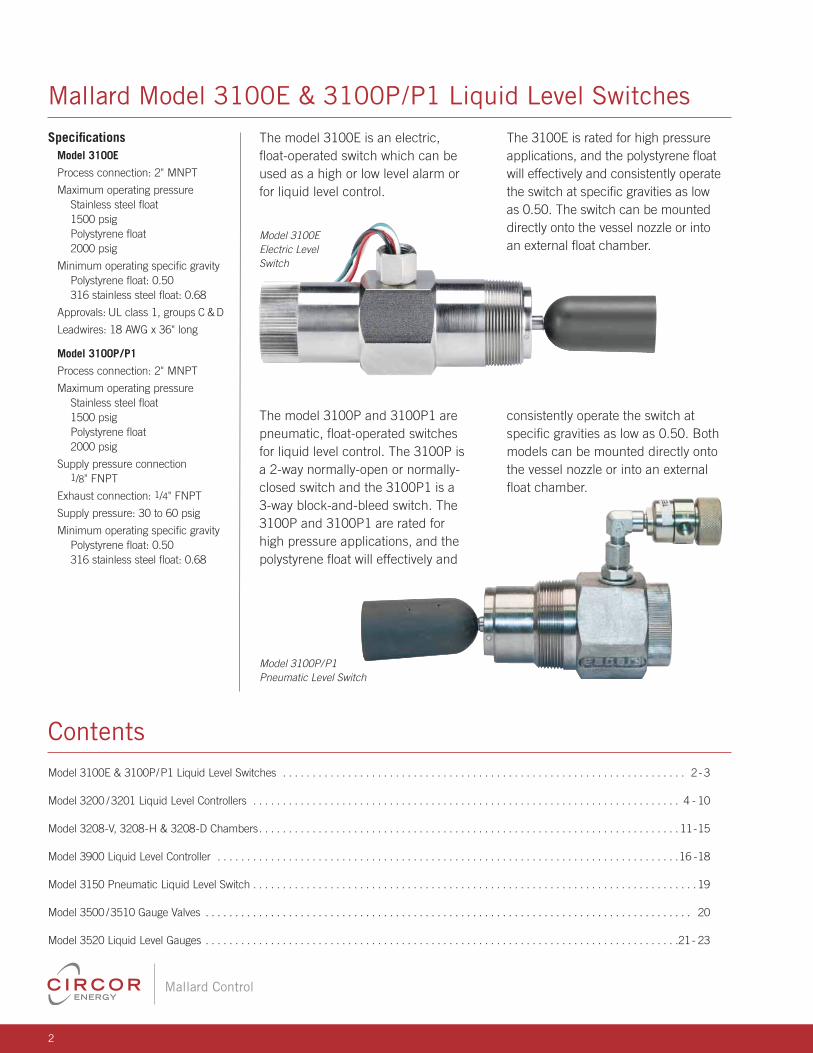
The model 3100E is an electric,
fl oat-operated switch which can be
used as a high or low level alarm or
for liquid level control.
The model 3100P and 3100P1 are
pneumatic, fl oat-operated switches
for liquid level control. The 3100P is
a 2-way normally-open or normally-
closed switch and the 3100P1 is a
3-way block-and-bleed switch. The
3100P and 3100P1 are rated for
high pressure applications, and the
polystyrene fl oat will effectively and
The 3100E is rated for high pressure
applications, and the polystyrene fl oat
will effectively and consistently operate
the switch at specifi c gravities as low
as 0.50. The switch can be mounted
directly onto the vessel nozzle or into
an external fl oat chamber.
consistently operate the switch at
specifi c gravities as low as 0.50. Both
models can be mounted directly onto
the vessel nozzle or into an external
fl oat chamber.
Specifi cationsModel 3100E
Process connection: 2" MNPT
Maximum operating pressure
Stainless steel fl oat
1500 psig
Polystyrene fl oat
2000 psig
Minimum operating specifi c gravity
Polystyrene fl oat: 0.50
316 stainless steel fl oat: 0.68
Approvals: UL class 1, groups C & D
Leadwires: 18 AWG x 36" long
Model 3100P/P1
Process connection: 2" MNPT
Maximum operating pressure
Stainless steel fl oat
1500 psig
Polystyrene fl oat
2000 psig
Supply pressure connection
1/8" FNPT
Exhaust connection: 1/4" FNPT
Supply pressure: 30 to 60 psig
Minimum operating specifi c gravity
Polystyrene fl oat: 0.50
316 stainless steel fl oat: 0.68
Mallard Model 3100E & 3100P/P1 Liquid Level Switches
Contents
Model 3100E & 3100P/P1 Liquid Level Switches . . . . . . . . . . . . . . . . . . . . . . . . . . . . . . . . . . . . . . . . . . . . . . . . . . . . . . . . . . . . . . . . . . . . 2 - 3
Model 3200 /3201 Liquid Level Controllers . . . . . . . . . . . . . . . . . . . . . . . . . . . . . . . . . . . . . . . . . . . . . . . . . . . . . . . . . . . . . . . . . . . . . . . . 4 - 10
Model 3208-V, 3208-H & 3208-D Chambers. . . . . . . . . . . . . . . . . . . . . . . . . . . . . . . . . . . . . . . . . . . . . . . . . . . . . . . . . . . . . . . . . . . . . . . 11-15
Model 3900 Liquid Level Controller . . . . . . . . . . . . . . . . . . . . . . . . . . . . . . . . . . . . . . . . . . . . . . . . . . . . . . . . . . . . . . . . . . . . . . . . . . . . . .16 -18
Model 3150 Pneumatic Liquid Level Switch . . . . . . . . . . . . . . . . . . . . . . . . . . . . . . . . . . . . . . . . . . . . . . . . . . . . . . . . . . . . . . . . . . . . . . . . . . . 19
Model 3500 /3510 Gauge Valves . . . . . . . . . . . . . . . . . . . . . . . . . . . . . . . . . . . . . . . . . . . . . . . . . . . . . . . . . . . . . . . . . . . . . . . . . . . . . . . . . . 20
Model 3520 Liquid Level Gauges . . . . . . . . . . . . . . . . . . . . . . . . . . . . . . . . . . . . . . . . . . . . . . . . . . . . . . . . . . . . . . . . . . . . . . . . . . . . . . . .21- 23
Model 3100E
Electric Level
Switch
Model 3100P/P1
Pneumatic Level Switch

3
Mallard Control
Mallard Model 3100E & 3100P/P1 Liquid Level Switches
Dimensional Data (in.)
101/2"
2 3/16"Ø
Model 3100E
27/16"
31/2"1/2" NPT
2"-111/2" NPT
Float travel between operate and reset point = 3Minimum movement of float required = 1/4")
31/2"
SPDT Switch Rating DPDT Switch Rating5A @ 125-250-480 VAC 10A @ 125-250 VAC1/2A @ 125 VDC 1/2A @ 125 VDC1/4A @ 250 VDC 1/4A @ 250 VDC2A @ 6-30 VDC Resistive 10A @ 6-24 VDC1A @ 6-30 VDC Inductive Inductive/Resistive
53/8" 61/8"
31/2"
85/8"
A
2" NPT
Section A-A1" NPT(2 Places)
External Float Chamber - P/N 31124-2 (Standard) P/N 31124N-2 (NACE)
81/16"
19/16"Ø23/16"Ø
31/2" 31/2" w/o Ext.
27/16"
2"-111/2 NPT
Float travel between operate and reset point = 80˚ Minimum movement of float required = 5"
Model 3100P/P1A
Temperature Limits Model 3100E & 3100P/P1 Polystyrene Float Stainless Steel Float -20 to 300°F (-29 to 200°C) -20 to 400°F (-29 to 204°C)
Part Number Codes, Model 3100E Part Model
Body Float
Switch Number Number (Viton® Seals) 91200 3100E CS Polystyrene SPDT
91201 3100E2 CS Polystyrene DPDT
91210 3100E2 CS SS DPDT
91219 3100E CS SS SPDT
91224 3100E2-SS SS SS DPDT
91225 3100E-SS SS SS SPDT
91227 3100E-SS SS Polystyrene SPDT
91232 3100E2-SS SS Polystyrene DPDT
Part Number Codes, Model 3100P/ P1
Materials of Construction Description Material
Body Low Temp CS (Plated)
316 Stainless Steel (Optional)
Float
Polystyrene
316 Stainless Steel (Optional)
Seals Viton®
Part Model Body
Float Pilot
Number Number (Viton® Seals) 91000 3100P CS Polystyrene No
91001 3100P1 CS SS, 1" Ext. Yes
91002 3100P CS SS No
91004 3100P1 CS SS Yes
91006 3100P1 CS Polystyrene Yes
91008 3100P-SS SS Polystyrene No
91025 3100P1-SS SS Polystyrene Yes
91026 3100P1-SS SS SS Yes
91027 3100P1-SS SS SS No
91206 3100P1 CS Poly., 1" Ext. Yes
91207 3100P CS Poly.,1" Ext. No

4
Mallard Control
Mallard Model 3200/3201 Liquid Level Controllers
The model 3200/3201 liquid
level controller is ideal for oilfi eld
scrubber and separator applications.
Its rugged and versatile design make
it the preferred choice of production
operators for reliable service in
a wide variety of applications.
Model 3200 is available in
pneumatic snap and throttling pilots,
or electric SPDT and DPDT limit
switches; direct or reverse action;
with a variety of displacer sizes,
materials, and vessel connections.
Features Pneumatic throttling, snap,
or ECO Pilot™: Pneumatic
model 3200/3201 can be
fi tted with any of the three
pneumatic pilots. A snap pilot
for on/off service, a throttle pilot
for modulating service, or
ECO pilot for environmentally
friendly, non-bleed applications.
The controller can be quickly
and easily converted from
one pilot style to another.
Electric pilots: The model 3200
is also available with explosion
proof SPDT or DPDT
electric switches.
Weather-proof case: Utilizes a
gasket between its cover and
case to seal out the effects of
outside weathering.
Liquid-liquid interface control:
The model 3200/3201 is
well suited for liquid-liquid
interface detection.
Field reversible action:
The model 3200/3201 design
makes reversing the controller
action simple. Requires no
additional parts or special tools.
Displacers: Mallard offers a
variety of displacer materials and
designs for the model 3200/3201
to satisfy your design and
application requirements.
Standard material offerings
are PVC, acrylic and
316 stainless steel.
Available with wetted materials
that meet NACE MR0175
specifi cations for sour service.
Specifi cations Available end connection sizes
Threaded & butt weld: 1.5" & 2"
Flanged: 2", 3", 4", 6" & 8"
Pilot
Pneumatic (standard)
Snap (on/off),
0-20 / 0-30 psig output
Throttle (modulating),
3-15/6-30 psig output
Electric (optional)
SPDT (explosion proof)
DPDT (explosion proof)
Supply pressure requirement
3-15 or 0-20 psig output
20-30 psig min.
6-30 or 0-30 psig output
35-40 psig min.
Electric switch rating
SPDT: 15 amps @ 125, 250 or 480 VAC
DPDT: 10 amps @ 125, 250 or 480 VAC
Supply & output connections
Pneumatic pilots: 1/4" FNPT
Electric switches: 1/2" FNPT
Pressure ratings
2" threaded: 6000 psig
Flanged: 6170 psig (2500#)
Materials of Construction Description Material Body Low Temp Carbon Steel
Case & Cover Die Cast Aluminum
Pilots Aluminum w/SS Internals
Pilot Gaskets / Buna
Diaphragm Viton® (Optional)
Brass or Brass LF
Gauges 316SS or
316SS LF (Optional)
Shaft
303 Stainless Steel
316 SS (Optional)
Bearing Blocks
303 Stainless Steel
316 SS (Optional)
Description Material Bearings 440C Stainless Steel
Seals
Buna-N
Viton® (Optional)
Displacer
PVC
Acrylic or 316 SS (Optional)
Displacer Arm 304 Stainless Steel
Vertical Hanger 316 Stainless Steel
(Swivel)
Vertical Displacer 302 Stainless Steel
Ext. Chain

5
Mallard Control
Controller Case00 • Sealed Case 01 • Standard Case
Arm Length– • 15" (Std.) F • 8" K • 10" P • 16"* U • 20"
B • 7" G • 8.5 L • 11" Q • 16.44" V • 21"
C • 7.19" H • 9" M • 12" R • 16.75" W • 22"
D • 7.25" I • 9.25" N • 12.5" S • 17"** Y • 24" (40MU Std.)
E • 7.75" J • 9.5" O • 14" T • 18" Z • 25"
*NPT Controller & Chamber Connection. ** Flanged Controller & Chamber Connection.
End Connection 15 • 1.5" 30 • 3" 50 • 5" (Hammer 60 • 6"
20 • 2" 40 • 4" Union Only) 80 • 8"
End Connection TypeMS • Screwed MNPT B8 • BW, Sched. 80 RF • RF Flange
MU • Hammer Union (4"-5" only) B1 • BW, Sched. 160 RJ • RTJ Flange
End Connection Rating0 • MNPT 6 • ANSI 600 2 • ANSI 2500
1 • ANSI 150 9 • ANSI 900 7 • Hammer Union w/Sight Glass
3 • ANSI 300 5 • ANSI 1500 8 • Hammer Union w/No Sight Glass
Materials of Construction: Body / Shaft & Bearing Block– • A350 LF2 / 303SS N • A350 LF2 / 316SS, NACE
A • A350 LF2 / 316SS S • 316SS / 316SS, NACE
PilotS • Snap (Pneumatic On/Off) D • DPDT, Double Pole Double Throw
T • Throttling (Pneumatic Modulating) (Elec. On/Off, Exp. Proof Housing)
E • SPDT, Single Pole Double Throw Z • ECO Pilot™ (Non-Bleed Snap)
(Electric On/Off, Exp. Proof Housing)
Mounting /Controller ActionLD • Left Hand / Direct RD • Right Hand / Direct
LR • Left Hand / Reverse RR • Right Hand / Reverse
Seal MaterialB • Buna V • Viton® A • Aflas® C • Low Temp Viton® L • Low Temp Nitrile
Displacer: Dimensions (in.) / Material– • 1.88 x 12 / PVC L • 1.88 x 14 / PVC Z • 3.00 x 10 / PVC
B • 1.5 x 10 / PVC M • 1.88 x 18 / PVC 0 • 1.66 x 12 / 316SS
C • 1.5 x 12 / Acrylic P • 1.88 x 6 / PVC 1 • 1.66 x 10 / 316SS
D • 1.5 x 12 / PVC R • 2.00 x 12 / Acrylic 2 • 1.66 x 6 / 316SS
E • 1.5 x 24 / Acrylic S • 2.00 x 12 / PVC 4 • 1.66 x 10 / 316SS, NACE
F • 1.5 x 6 / PVC T • 2.00 x 14 / Acrylic 5 • 1.66 x 12 / 316SS, NACE
H • 1.88 x 10 / Acrylic U • 2.00 x 14 / PVC 6 • 1.66 x 14 / 316SS
I • 1.88 x 10 / PVC V • 2.75 x 12 / PVC 7 • 1.66 x 18 / 316SS
J • 1.88 x 12 / Acrylic W • 2.75 x 5 / Acrylic 8 • 1.66 x 24 / 316SS
K • 1.88 x 14 / Acrylic Y • 2.75 x 5 / PVC 9 • 1.66 x 30 / 316SS
Gauge Type: Pressure Range / Internal MaterialS • 0-30 psi / Brass (Standard) B • 0-60 psi / Brass, Liquid-Filled
T • 0-60 psi / Brass (Standard) C • 0-30 psi / 316SS, Liquid-Filled
3 • 0-30 psi / 316SS D • 0-60 psi / 316SS, Liquid-Filled
6 • 0-60 psi / 316SS E • Electric (E & D Pilot Options Only)
A • 0-30 psi / Brass, Liquid-Filled
EnclosureA • Std. Case (3201) M • Marine Service (3200) N • Marine Service w/Piped
S • Std. Case (3200) P • Piped Exhaust (3200) Exhaust (3200)
3201- 20 MS 0 - S RD B - S AExample
Mallard Model 3200/3201 Part Number Codes

6
Mallard Control
Displacer
Displacer Arm
Shaft
TorqueBar Arm
Spring
Mallard Model 3200/3201 Liquid Level Controllers
Operating Temperature Limits Body
Seals Displacer Temperature Limits
Material Material ˚F ˚C Low Temp PVC -40 to 140 -40 to 60
Viton® and/or Buna Acrylic -40 to 180 -40 to 82
Buna with 316SS -40 to 225 -40 to 107
Min. Temp. PVC -20 to 140 -29 to 60
Rating of Viton® Acrylic -20 to 200 -29 to 93
-50˚F (-46˚C) 316SS -20 to 400 -29 to 204
Theory of Operation The operation of the model 3200
liquid Level controller is based
upon the “force balance principle”.
The weight of a displacer-type
level sensing element produces a
force which is applied to one side
of the torque bar through a series
of shafts and levers. This force is
balanced by the opposing force of
a compressed spring on the other
side of the torque bar. As the level
rises, the increased immersion of
the displacer in the liquid causes
the relative weight of the displacer
to decrease, due to the buoyancy
force being produced. This, in
turn, results in a decrease in force
applied to the torque bar. The
torque bar then rotates until the
forces are again balanced. Torque
bar rotation is detected by the
pilot through a fulcrum mounted
on a lever (fl apper bar) to affect
the desired controller output. The
output signal can be a pneumatic
on/off signal by using the snap
pilot, a pneumatic modulating
signal by using the throttle pilot,
or it can be an electrical SPDT or
DPDT output signal by using an
electric limit switch.
Information Required for Proper Selection of the 3200 Liquid Level Controller
Fluid media
Fluid temperature maximum & minimum
Operating & design pressure
Body connection size & type
Displacer orientation: Horizontal & vertical
Displacer arm length: Arm length is fi gured from
the centerline of the controller case to where
the displacer attaches to the arm. Standard
arm lengths are 12.5" for horizontal displacers
and 15" for vertical displacers. Other arm
lengths are available upon request.
Determine mounting orientation
Displacer Pressure Ratings Displacer Material Maximum Pressure (psig) PVC 6170
Acrylic 6170
316 Stainless Steel
2000 at 180˚F (82˚C)
1595 at 400˚F (204˚C)*
*For applications requiring higher pressure ratings for SS displacers,
consult factory or your local Mallard representative.
Minimum Allowable Fluid Specifi c Gravity Top Level Control Liquid-Liquid Interface Level Control Pilot Horizontal Displacer Vertical Displacer Horizontal Displacer Vertical Displacer Standard1 Standard2 Standard1 Special3 Standard2 Special3
Snap 0.28 0.21 0.28 0.030 0.21 0.050
Throttle 0.56 0.42 0.56 0.060 0.42 0.100
1. Based on 1.88" dia. x 12" displacer with 12" displacer arm.
2. Based on 1.88" dia. x 12" displacer with 15" displacer arm.
3. Special displacer and displacer arm confi gurations required. Consult factory or your local Mallard representative.

7
Mallard Control
Mallard Model 3200/3201 Action & Mounting
Left-Hand Mount Direct Acting
Left-Hand Mount Reverse Acting Right-Hand Mount Reverse Acting
Right-Hand Mount Direct Acting
Flapper Bar
Pivot
Fulcrum
Flapper Bar
Pivot
Fulcrum
FlapperBar
Pivot
Fulcrum
FlapperBar
Pivot
Fulcrum
Proportional Band Proportional band is the ratio of used
displacer length versus the total length of
the displacer to achieve a desired output
signal. Example: If six inches of liquid
level change will develop the required
output signal (such as 3-15 psi) and a
12" long vertical displacer is used, then
the level controller is said to have a 50%
proportional band. Sliding the fulcrum
on the fl apper bar away from the pivot
pin toward the snap ring decreases
proportional band (increases sensitivity),
while sliding the fulcrum on the fl apper
bar away from the snap ring toward the
pivot pin increases proportional band
(decreases sensitivity). A desired output
signal (such as 3-15 psi or 6-30 psi)
may be accomplished over any portion of
the displacer by adjusting the fulcrum as
described above.
Controller ActionController action is determined by the
installation of the fl apper bar, as shown
above. Control is considered “direct
acting” when the controller output
changes in the controller output signal
will increase when the liquid level the
controller is sensing increases, and vice
versa. Control is considered “reverse
acting” when the controller output
changes in the opposite direction as the
liquid level. For a direct acting controller,
the fl apper bar pivot point is on the same
side as the spring. For a reverse acting
controller, the fl apper bar pivot point is on
the opposite side as the spring.
Mounting The model 3200 liquid level
controller can be set up as
right-hand or left-hand mount. The
orientation of the level controller
mounted to the vessel, while
facing the front of the controller,
determines the mounting style. If
the controller is to be mounted on
the right side of the vessel, then
it is considered “right-hand”. If
the controller is to be mounted
on the left side of the vessel, then
it is considered “left-hand”. The
mounting orientation can be easily
reversed in the fi eld.

8
Mallard Control
Mallard Model 3200/3201 Pilot Operation
Snap Pilot Throttle Pilot
Y
Output
Supply
X
Exhaust
Y
Output
Supply
X
Exhaust
Snap Pilot Operation The snap pilot is made up of two
valves. One to admit system supply
pressure and one to exhaust
system pressure. Ball “X” controls
the fl ow of supply gas into the pilot
and is held closed on the pilot seat
by force exerted by the supply
pressure acting upon the seating
area of the ball.
When force transmitted from the
fl apper bar to the thrust pin “Y”
becomes suffi cient to overcome
the force holding ball “X” seated,
ball “X” snaps off the pilot seat
allowing supply gas to fl ow past
ball “X” and through the output
port of the pilot. The spherical
seating end of the thrust pin “Y”
seats and closes the exhaust port
simultaneously when ball “X”
snaps open. The seating area of
the thrust pin is smaller than the
seating area of ball “X”; therefore,
the thrust pin must remain seated
against the supply pressure until
force on the thrust pin from the
fl apper bar diminishes.
Throttle Pilot Operation The throttle pilot, like the snap pilot, is
also made up of two internal valves. In
addition, the throttle pilot utilizes a resilient
diaphragm “Z” in conjunction with the
valves to create a force balance pilot.
The pilot output supply pressure acts upon
the diaphragm “Z” so that the diaphragm
pushes back with the same force being
applied to the thrust pin by the fl apper bar,
thus the term force balance.
The throttle pilot functions in a similar
manner as the snap pilot except that the
output pressure is proportional to the
amount of force applied to the lower seat
by the fl apper bar. An increase in force on
the thrust pin produces a proportionate
increase in pilot output pressure.
As forces change on the thrust pin,
the pilot seeks a new balance point by
exhausting the supply output at valve “Y”
or unseating valve “X” to increase output
pressure. Supply gas does not fl ow while
the pilot is in balance.
A simultaneous action occurs as force from
the fl apper bar on the thrust pin “Y” is
removed. When this happens, the supply
pressure will unseat the thrust pin and
open the exhaust port in the pilot and ball
“X” will reseat and close off the supply
port. The difference in seating areas gives
this pilot its “snap” action.
The Mallard ECO Pilot™ is an easy and
affordable solution to convert your existing
level controllers to a more effi cient
non-bleed design. By reducing fugitive
emissions into the atmosphere, oil & gas
operators regain lost profi ts while lowering
their carbon footprint.
These simple modifi cataions may soon
provide another benefi t. According to the
Clean Air act and EPA STAR program,
such modifi cations may soon qualify users
to earn valuable carbon credits as well.
9
Mallard Control
7.85"
4.13"
3.85"
8.74"
4.87"
FSee Table Below
16.15" (1)
24.50" (1)
5.19"0.69"
4.36"
3.95"
7.47"
Model 3200 Model 3201
0.69"
7.98"7.13"
1.90"
2.98"
4.31"
3.44"
3.06"
6.59"
7.98"
6.00"
.88"
1.00"
4.56"
4.00"
.250-18 NPT
.250-18 NPT
2.98"
8.01"
Model 3200 Back View Model 3201 Back View
7.06"
2.69"
1.00"
8.01"
7.06"
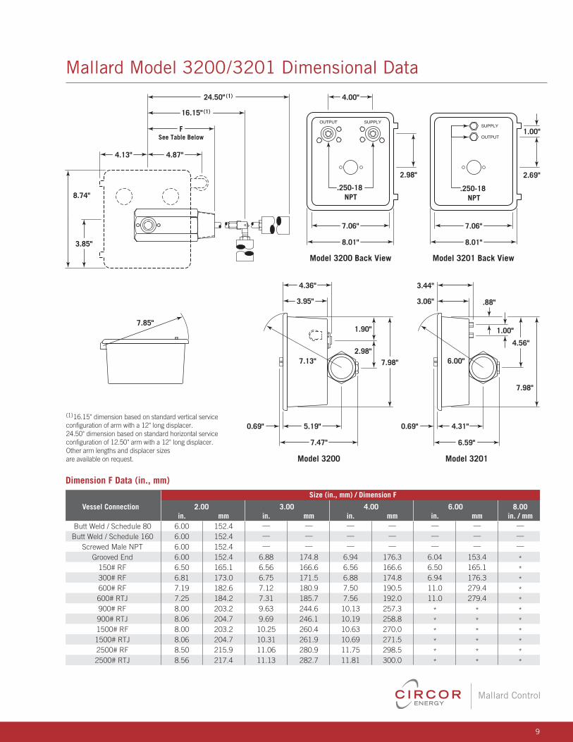
(1)16.15" dimension based on standard vertical service configuration of arm with a 12" long displacer. 24.50" dimension based on standard horizontal service configuration of 12.50" arm with a 12" long displacer.Other arm lengths and displacer sizes are available on request.
Mallard Model 3200/3201 Dimensional Data
Dimension F Data (in., mm) Size (in., mm) / Dimension F
Vessel Connection 2.00 3.00 4.00 6.00 8.00 in. mm in. mm in. mm in. mm in. / mm Butt Weld / Schedule 80 6.00 152.4 — — — — — — —
Butt Weld / Schedule 160 6.00 152.4 — — — — — — —
Screwed Male NPT 6.00 152.4 — — — — — — —
Grooved End 6.00 152.4 6.88 174.8 6.94 176.3 6.04 153.4 *
150# RF 6.50 165.1 6.56 166.6 6.56 166.6 6.50 165.1 *
300# RF 6.81 173.0 6.75 171.5 6.88 174.8 6.94 176.3 *
600# RF 7.19 182.6 7.12 180.9 7.50 190.5 11.0 279.4 *
600# RTJ 7.25 184.2 7.31 185.7 7.56 192.0 11.0 279.4 *
900# RF 8.00 203.2 9.63 244.6 10.13 257.3 * * *
900# RTJ 8.06 204.7 9.69 246.1 10.19 258.8 * * *
1500# RF 8.00 203.2 10.25 260.4 10.63 270.0 * * *
1500# RTJ 8.06 204.7 10.31 261.9 10.69 271.5 * * *
2500# RF 8.50 215.9 11.06 280.9 11.75 298.5 * * *
2500# RTJ 8.56 217.4 11.13 282.7 11.81 300.0 * * *

10
Mallard Control
Mallard Model 40MU Hammer Union Connection
Hammer nut closure designed to be
used in conjunction with the model
3200/3201 liquid level controller.
Features Hammer nut closure for quick
& easy installation & removal
Built-in sight glasses for
local liquid level indication
Options 8" long mating pipe nipple
NACE MR0175 compliance
Specifi cations Process connection size & type
4" Mallard hammer nut union
Pressure rating: 1500 psig
Max. pressure rating at 100˚F (38˚C).
Rating dependent on displacer selection
Materials of Construction Description Material
Body Low Temp Carbon Steel
Hammer Nut Carbon Steel
8" Union Nipple Carbon Steel
Sightglasses Acrylic
Refl ector 316 Stainless Steel
Description Material
Seals Buna
Viton® (Optional)
Offset Connector 316 Stainless Steel
Displacer Arms 304 Stainless Steel
3.50" Radius
4.13"
3.85"
Ø4.50"
Optional Pipe Nipple
4.89"
8.74"
7.00" 3.12"
.81"
1.69"
11.12" 8.00"
B
A
D
C
0.69"
Dimensional Data (in.)
The Mallard union also incorporates
compact sight glasses for liquid level
indication at the entry point of the
level control into the vessel.
See page 5 for part number codes and ordering information.

11
Mallard Control
Mallard Model 3208-V Vertical Style Chamber
Designed to be used with the
3200/3201 liquid level controller
in applications where internal
obstructions prevent direct
installation of the level control,
or to isolate the level control from
fl uid turbulence within the vessel.
Features Rotatable head design
NACE MR0175
compliance option
Available with threaded
or fl anged controller &
vessel connections
Specifi cations Level controller connection
2" threaded or fl anged
Vessel connection: 1", 11/2" & 2"Materials of Construction Description Material
Chamber & Carbon Steel or 316SS
Dome
ASTM A193-B7
Studs
ASTM A193-B8M (Opt.)
ASTM A194-2H
Nuts
ASTM A193-8M (Opt.)
316 / Grf. CS Gr.
Gasket Inconel® /
Grf 316SS Gr. (Opt.)
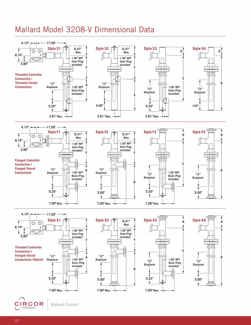
Dimensional Data (in., mm)
Dim. Style Displacer Length
in. mm in. mm
A
S1, F1, 14 355.6 14 355.6
X1 32 812.8 32 812.8
B F2, X2
14 355.6 19 482.6
32 812.8 37 939.8
C
S3, F3, 14 355.6 15 381.0
X3 32 812.8 33 838.2
D
S4, F4, 14 355.6 20 508.0
X4 32 812.8 38 965.2
E S2
14 355.6 18 457.2
32 812.8 36 914.4
Dim. Style
Chamber Vessel Connection in. mm
Size Size Rating
3" All ANSI 150,
14.25 362.0
S1, S2, 300 & 600
F F1, F2,
4" All ANSI 150 & 300 14.25 362.0
X1, X2
4" All As Required 18.00 457.2
G S3, S4
3" All All 4.91 124.7
4" All All 5.72 145.3
150# RF 7.10 180.3
F3, 1" 300# RF 7.35 186.7
H
F4, 3"
600# RF 7.60 193.0
X3, 150# RF 7.35 186.7
X4 11/2" 300# RF 7.60 193.0
600# RF 7.91 200.9
Dim. Style
Chamber Vessel Connection in. mm
Size Size Rating 150# RF 7.41 188.2
3" 2" 300# RF 7.66 194.6
600# RF 8.04 204.2
150# RF 7.91 200.9
F3, 1" 300# RF 8.16 207.3
H
F4, 600# RF 8.41 213.6
X3, 150# RF 8.16 207.3
X4 4" 11/2" 300# RF 8.41 213.6
600# RF 8.72 221.5
150# RF 8.22 208.8
2" 300# RF 8.47 215.1
600# RF 8.85 224.8
12
Mallard Control
8.74"
Threaded Controller Connection / Threaded Vessel Connections
3.85"
Style S14.13" 17.56"
6.41"Max.
6.41"Max.
6.41"Max.
6.41"Max.
F
A1/2"
Displacer
1/2"Displacer 1/2"
Displacer
1/2"Displacer 1/2"
Displacer
1/2"Displacer 1/2"
Displacer
5.25"
3.81" Max.
7.00" Max.
7.00" Max. 7.00" Max. 7.00" Max.
7.00" Max. 7.00" Max.
3.81" Max. 3.81" Max.
1.00" NPT Vent (Plug Included)
1.00" NPT Vent (Plug Included)
6.41"Max.
1.00" NPT Vent (Plug Included)
1.00" NPT Drain (Plug Included)
1.00" NPT Drain (Plug Included)
8.74"
Flanged Controller Connection / Flanged Vessel Connections
3.85"
Style F14.13" 17.56"
F
A
F
A
5.25"
1/2"Displacer
1/2"Displacer 1/2"
Displacer1/2"
Displacer
5.25"
1.00" NPT Vent (Plug Included)
1.00" NPT Vent (Plug Included)
1.00" NPT Drain (Plug Included)
1.00" NPT Vent (Plug Included)
1.00" NPT Drain (Plug Included)
1.00" NPT Drain (Plug Included)
1.00" NPT Drain (Plug Included)
8.74"
Threaded Controller Connection / Flanged Vessel Connections (Hybrid)
3.85"
Style X1
4.13" 17.56"
Style S2
E
4.00"
F
Style F2
F
B
F
B
5.00" 5.00"
Style X2
5.00"
Style S4
4.00"
G
D
1/2"Displacer
Style F4H
D
Style X4 H
D
5.00"
Style S3G
C
5.25"
Style F3H
C
5.25"
Style X3 H
C
5.25"
Mallard Model 3208-V Dimensional Data
13
Mallard Control
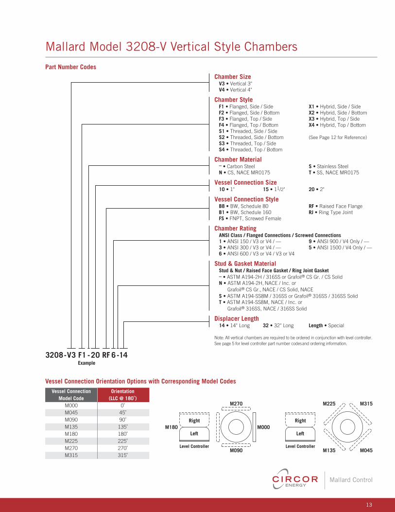
Mallard Model 3208-V Vertical Style Chambers
3208 -V3 F1 -20 RF 6 -14
Chamber SizeV3 • Vertical 3"
V4 • Vertical 4"
Chamber StyleF1 • Flanged, Side / Side X1 • Hybrid, Side / Side
F2 • Flanged, Side / Bottom X2 • Hybrid, Side / Bottom
F3 • Flanged, Top / Side X3 • Hybrid, Top / Side
F4 • Flanged, Top / Bottom X4 • Hybrid, Top / Bottom
S1 • Threaded, Side / Side
S2 • Threaded, Side / Bottom (See Page 12 for Reference)
S3 • Threaded, Top / Side
S4 • Threaded, Top / Bottom
Chamber Material– • Carbon Steel S • Stainless Steel
N • CS, NACE MR0175 T • SS, NACE MR0175
Vessel Connection Size10 • 1" 15 • 11/2" 20 • 2"
Vessel Connection StyleB8 • BW, Schedule 80 RF • Raised Face Flange
B1 • BW, Schedule 160 RJ • Ring Type Joint
FS • FNPT, Screwed Female
Chamber RatingANSI Class / Flanged Connections / Screwed Connections1 • ANSI 150 / V3 or V4 / — 9 • ANSI 900 / V4 Only / —
3 • ANSI 300 / V3 or V4 / — 5 • ANSI 1500 / V4 Only / —
6 • ANSI 600 / V3 or V4 / V3 or V4
Stud & Gasket Material Stud & Nut / Raised Face Gasket / Ring Joint Gasket– • ASTM A194-2H / 316SS or Grafoil® CS Gr. / CS Solid
N • ASTM A194-2H, NACE / Inc. or
Grafoil® CS Gr., NACE / CS Solid, NACE
S • ASTM A194-SS8M / 316SS or Grafoil® 316SS / 316SS Solid
T • ASTM A194-SS8M, NACE / Inc. or
Grafoil® 316SS, NACE / 316SS Solid
Displacer Length14 • 14" Long 32 • 32" Long Length • Special
Note: All vertical chambers are required to be ordered in conjunction with level controller.
See page 5 for level controller part number codesand ordering information.
Example
Right
Left
Level Controller
M180 M000
M090 M135 M045
M270 M225 M315
Right
Left
Level Controller
Part Number Codes
Vessel Connection Orientation Options with Corresponding Model Codes Vessel Connection Orientation Model Code (LLC @ 180˚) M000 0˚
M045 45˚
M090 90˚
M135 135˚
M180 180˚
M225 225˚
M270 270˚
M315 315˚

14
Mallard Control
3208-D4 2S- 40 RF 6
Dome SizeD2 • 2" D3 • 3" D4 • 4"
Level Controller Connection2F • 2" Flanged 2S • 2" FNPT
Chamber Material– • Carbon Steel S • 316 Stainless Steel
N • CS, NACE MR0175 T • 316 SS, NACE MR0175
Vessel Connection Size20 • 2" 30 • 3" 40 • 4"
Vessel Connection StyleRF • Raised Face Flange RJ • Ring Type Joint
Vessel Connection Rating1 • ANSI 150 (285 psig) 9 • ANSI 900 (2220 psig)
3 • ANSI 300 (740 psig) 5 • ANSI 1500 (3705 psig)
6 • ANSI 600 (1480 psig) 2 • ANSI 2500 (6170 psig)
Example
Mallard Model 3208-H/3208-D Chambers
Features Compact design for
limited spaces
Threaded level controller
& vessel connections
Specifi cations Level controller connection
2" threaded FNPT
Vessel connection
1" threaded FNPT
Materials of construction
Carbon steel or 316 stainless steel
Maximum pressure rating
2000 psi
Features Screwed or fl anged level
controller connections
Multiple vessel connection
sizes & fl ange ratings
(ANSI 150 through 2500)
NACE MR0175
compliance option
Specifi cations Level controller connection
2" FNPT or ANSI fl ange
Vessel connection sizes: 2", 3" & 4"
Materials of construction
Carbon steel or 316 stainless steel
The model 3208-D dome style chamber is
designed to be used with the 3200/3201 liquid
level controller in applications where the vessel
connection is located on top of the vessel.
internal obstructions prevent direct
installation of the level control, or to
isolate the level control from fl uid
turbulence within the vessel.
The model 3208-H horizontal style
chamber is designed to be used
with the 3200/3201 liquid level
controller in applications where
Part Number Codes
Model 3208-H
Horizontal Style Chamber
Model 3208-D
Horizontal Style Chamber

15
Mallard Control
8.32"
Model 3208-H
1" NPT (Typ. 2 Places)
3.82"
LLC • Left Hand Mount (Ref.)
8.75"
25.75"
13.31"
3.00"
6.00"
Mallard Model 3208-H/3208-D Dimensional Data
8.74"
Model 3208-D • Dome Style SNPT Level Controller Connection
Model 3208-D • Dome Style FFlanged Level Controller Connection
4.13" 17.56"
6.41"Max.
A
8.74"
4.13" 17.56"
1.00" NPT Plug
1.00" NPT Plug
6.41"Max.
A
Dimension A Data (in., mm) End Dome Size (in.) / Dimension A Connection 2.00 3.00 4.00 150 RF 5.00 6.19 7.19
300 RF 5.25 6.56 7.56
600 RF 5.56 6.93 8.44
600 RTJ 5.62 7.00 8.50
900 RF 6.69 7.69 8.94
900 RTJ 6.75 7.75 9.00
1500 RF 6.69 8.31 9.31
1500 RTJ 6.75 8.38 9.38
2500 RF 7.69 10.31 11.69
2500 RTJ 7.75 10.37 11.75
Dome Size (mm) / Dimension A 150 RF 127.0 157.2 182.6
300 RF 133.4 166.6 192.0
600 RF 141.2 176.0 214.4
600 RTJ 142.8 177.8 215.9
900 RF 169.9 195.3 227.1
900 RTJ 171.5 196.9 228.6
1500 RF 169.9 211.1 237.5
1500 RTJ 171.5 212.9 238.3
2500 RF 195.3 261.9 296.9
2500 RTJ 196.9 263.4 298.5

16
Mallard Control
Mallard Model 3900 Liquid Level Controller
Features Electric or pneumatic:
Can be fi tted with either a
non-bleeding pneumatic snap
(on/off) pilot or a SPDT or DPDT
electric switch.
Field reversible switch action:
Changing switch action requires
no special tools, no additional
parts, and can be easily done
without removing the instrument
from the vessel. Refer to the
switch action section on
page 17.
Field reversible mounting:
Simply follow the instructions
provided on the inside of the
instrument's cover. No special
tools and no additional parts
are required.
Comes standard with stainless
steel internals for marine
type environments.
Can be made to meet NACE
MR0175 material specifi cations
for sour service.
Specifi cations Process connection
Threaded: 1" FNPT
Flanged: 2"
Butt weld: 1", 1.5" & 2"
Socket weld: 1"
Temperature limit:
-20 to 400°F (-29 to 204°C)
Switch type
Pneumatic snap pilot (on/off),
(standard)
Electric SPDT (optional)
Rated class I, groups C & D
Rated class II, groups E, F, G
Electric DPDT, optional
Rated class I, groups B, C & D
Rated class II, groups E, F & G
Min. allowable fl uid specifi c gravity
Snap pilot: 0.50
SPDT switch: 0.50
DPDT switch: 0.75
Supply pressure requirements
(Pneumatic pilot)
0-20 psig output: 25 psig supply
0-30 psig output: 35 psig supply
The model 3900 liquid level
controller is a pneumatic snap
acting or electric SPDT or DPDT
high / low level switch. This rugged
instrument applies the same “force
balance” control mechanism as the
model 3200 liquid level controller,
combined with a compact vertical
cage assembly. The model 3900 is
designed specifi cally to meet the
level control requirements found on
onshore and offshore oil and gas
production equipment.
Electric switch rating
SPDT: 15A @ 125, 250 or 480 VAC
DPDT: 10A @ 125 or 250 VAC
Supply & output connections
Pneumatic pilot: 1/4" FNPT
Electric switch
1/2" FNPT (conduit connection)
Materials of Construction Level Switch Description Material Case & Cover Anodized Die-Cast Alum.
Anodized Aluminum
Snap Pilot with Aluminum Seat &
Stainless Steel Internals
Brass Internals (Std.)
316 SS Internals (Opt.)
316 Stainless Steel,
Gauges
Liquid-Filled (Opt.)
Brass Internals,
Liquid-Filled (Opt.)
Cage & Body Assembly Description Material Chamber Carbon Steel
Body Carbon Steel
Displacer
316 SS (Std.)
Alloy 20 (Opt. for NACE)
Displacer Arm 304 Stainless Steel
Seals
Viton® (Std.)
Buna-N (Opt.)
Pressure Ratings, Displacer Cage End Connection Pressure Rating (psig) FNPT, BW, SW 2250
150 RF 285
300 RF 740
600 RF/RTJ 1480
900 RF/RTJ 2220

17
Mallard Control
3900 -10 FS - S V RD-S M
Process Connection Size 10 • 1" 15 • 1.5" 20 • 2"
Process Connection StyleFS • FNPT, Screwed (1" Only) F6 • Flng. RF, ANSI 600
SW • SW F9 • Flng. RF, ANSI 900
B4 • BW, Sched. 40 J1 • Flng. RTJ, ANSI 150
B8 • BW, Sched. 80 J3 • Flng. RTJ, ANSI 300
B1 • BW, Sched. 160 J6 • Flng. RTJ, ANSI 600
F1 • Flng. RF, ANSI 150 J9 • Flng. RTJ, ANSI 900
F3 • Flng. RF, ANSI 300
Controller MaterialsCage & Body / Displacer / Shaft & Block Bearing– • CS / 316 SS / 303 SS N • CS, NACE /Alloy 20 /316 SS
A • CS / 316 SS / 316 SS
PilotD • Electric DPDT (Explosion Proof) S • Pneumatic Snap
E • Electric SPDT (Explosion Proof) Z • ECO Pilot™ (Non-Bleed)
Seal MaterialV • Viton® (Standard) B • Buna-N
Mounting Orientation / Switch ActionLD • Left Hand / Direct (Open Pneumatic Pilot on Rising Level)
LR • Left Hand / Reverse (Open Pneumatic Pilot on Falling Level)
LE • Left Hand / Electric Pilot
RD • Right Hand / Direct (Open Pneumatic Pilot on Rising Level)
RR • Right Hand / Reverse (Open Pneumatic Pilot on Falling Level)
RE • Right Hand / Electric Pilot
Supply/Output Gauges (0-60 psi) S • Brass (Standard) 6 • 316 SS E • Electric
B • Brass, Liquid-Filled D • 316 SS, Liquid-Filled
CaseM • Marine Service N • Marine Service w /Piped Exhaust
Example
Mallard Model 3900 Liquid Level Controller
Part Number Codes
Switch Action
Action refers to the change in instrument
output that results from a change in
instrument input. The input is the liquid
level, which is detected through the
mechanical force applied to the instrument
linkage from the relative weight of the
displacer. The output is the “making” or
“breaking” of a circuit. A reverse acting
level switch is one that “breaks” a circuit
on rising level. A direct acting level switch
is one that “makes” a circuit on rising level.
The model 3900 liquid level switch is
available in either direct or reverse acting
confi gurations. For switches equipped
with the pneumatic snap pilot, "making"
the pneumatic circuit means connecting
supply air to the output port in order
to pressurize a signal-receiving device.
"Breaking" the pneumatic circuit is done
by connecting the exhaust port to the
output port to remove pressure from the
signal-receiving device. Changing the
switch action is done by moving the fl apper
bar pivot point to the opposite side of the
switch housing. This is easily performed in
the fi eld and requires no special tools. For
switches equipped with electric SPDT or
DPDT pilots, “making” the electrical circuit
means closing the electrical contacts,
while “breaking” the circuit means opening
the electrical contacts. The switc h is
supplied with three leadwires per set of
contacts - “C” (common), “NO” (normally
open) and “NC” (normally closed) - and a
ground leadwire. A direct acting
switch (contacts to close on rising
level) is achieved by using “C”
and “NO” wires. A reverse acting
switch (contacts to open on rising
level) is achieved by using “C” and
“NC” wires.
Important Note: Moving the fl apper
bar pivot point is not necessary to
change switch action for electrical
switches. All model 3900 switches
with electric pilots are shipped
from the factory conforming to the
above wiring requirements. If the
fl apper bar pivot point is reversed,
the action of the switch contacts
will be reversed.

18
Mallard Control
8.74"
17.00"
10.00" 3.00"
3.85"
1.00"NPT
0.25" NPTSupply & Output
Connections
0.125" NPTExhaust Port
7.85" Radius
15.00" Radius
.91"
11.25"
8.88"1.69"Typical
5.88"
7.12"Radius1.50"
8.25"
1.50"1" NPT
1" NPT4.00"2.09"1.12"
0.50" NPTConnection
4.88"
Mallard Model 3900 Liquid Level Controller
Dimensional Data (in.)
Approximate Shipping Weight (lbs., kg)
End Process Connection (in.) / Weight (lbs., kg)
1 1.5 2
Connection lbs. kg lbs. kg lbs. kg
FNPT 47 21 — — — —
Butt Weld — — — — 47 21
Socket Weld 47 21 — — — —
150# RF 52 23 54 25 59 27
End
Process Connection (in.) / Weight (lbs., kg) 1 1.5 2
Connection lbs. kg lbs. kg lbs. kg
300# RF 55 25 59 27 63 29
600# RF/RTJ 55 25 63 29 67 31
900# RF/RTJ 64 29 81 37 95 43
Note: Top/bottom connection only

19
Mallard Control
3150 -2T 1
Body Size/ End Connection2T • 2" Threaded
4U • 4" Union
Float1 • 2" x 6"
2 • 3" x 6"
3 • 3.5" x 6"
OptionsBlank • None
N • 4" x 5" Nipple
Example
Part Number Codes
Mallard Model 3150 Pneumatic Liquid Level Switch
Simple pneumatic level switch
device designed for low pressure
applications. Available with either 2"
NPT or 4" union vessel connection,
Features Pneumatic pilot
Cost effective
2" threaded or 4"
union connections
Choice of fl oat size & fl oat
arm extension length
Specifi cations Body size
2" threaded & 4" union
Operating pressure limit: 500 psi
Operating temperature limits
-20 to 212˚F (-29 to 100˚C)
Supply pressure: 75 psi
3-way pilot connections: 1/4" FNPT
6.25"7.25"
2" NPT w/Standard Float & Arm 4" Union w/Standard Float & Arm
6"
2"
4.5"
6.19"7.16"6"
3.5"
4.43"
the model 3150 is designed with few
moving parts to provide consistent,
dependable service.
Dimensional Data (in.)
Materials of Construction Description Material Body Ductile Iron
Float Stainless Steel
Float Arm Stainless Steel
Seals Buna
Bushing Brass
Pressure Rating (psi)
Float Size (in.) Working Collapse Pressure Pressure 2 x 6 500 720
3.5 x 6 500 800
3 x 6 500 850
Float Pressure Ratings

20
Mallard Control
Mallard Model 3500/3510 Gauge Valves
Features Safety shutoff: Equipped with a
stainless steel ball check located
upstream of the seat, which
instantaneously shuts off fl ow
of medium in case of gauge
glass breakage.
Union gauge connection:
Allows top and bottom connected
gauges to be rotated to any angle
for convenient visibility. Enables
gauge removal without removing
the gauge valves, a signifi cant
time saver.
Offset pattern: Gauge and drain
connections are offset 0.75" from
the vessel connection centerline,
enabling the glass liquid level
gauge to be cleaned in place.
Materials of construction which
comply with NACE MR0175
specifi cations are available
on request.
Specifi cations Gauge connections
1/2" or 3/4" FNPT, rigid or union
Vessel connection
1/2" or 3/4" MNPT, union only
Seating service
Integral to valve body
Approximate weight
5.5 lbs. (2.49 kg)
Maximum operating pressure
4000 psi
The model 3500 (rigid-union) and
model 3510 (union-union) gauge
valves are recommended for use
with model 3520 glass liquid level
gauges and are compatible with all
armored fl at-glass liquid level gauges.
Consistent with Mallard's reputation,
the model 3500 is designed and built
to the highest standards.
Materials of Construction Description Material
Body
Low Temperature
Carbon Steel
Stem
416SS (Standard)
316 SS (NACE Option)
Ball Check 302 Stainless Steel
Handwheel Cast Iron
Gauge Vent / Drain Connection (in.) Connection (in.) Model 3500 Model 3510 1/2 NPT 1/2 NPT 1/2 NPT
3/4 NPT 3/4 NPT 3/4 NPT
Vent & Drain Connections
3500 - 2
Gauge-Vessel Connection Style00 • Rigid-Union 10 • Union-Union
Connection SizeGauge Connection / Vessel Connection 1 • 1/2" FNPT / 1/2" MNPT
2 • 1/2" FNPT / 3/4" MNPT
3 • 3/4" FNPT / 1/2" MNPT
4 • 3/4" FNPT / 3/4" MNPT
Materials of ConstructionBlank • Carbon Steel,Standard Service
N • Carbon Steel, NACE MR0175
Note: Sold in two-piece sets.
Example
Part Number Codes
Model 3500
Rigid-Union Gauge Valve
Model 3510
Rigid-Union Gauge Valve
21
Mallard Control
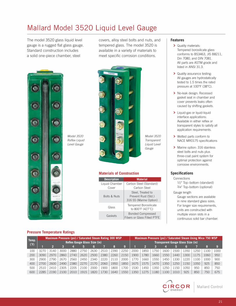
Mallard Model 3520 Liquid Level Gauge
The model 3520 glass liquid level
gauge is a rugged fl at glass gauge.
Standard construction includes
a solid one-piece chamber, steel
Features Quality materials:
Tempered borosilicate glass
conforms to BS3463, JIS B8211,
Din 7080, and DIN 7081.
All parts are ASTM grade and
listed in ANSI 31.3.
Quality assurance testing:
All gauges are hydrostatically
tested to 1.5 times the rated
pressure at 100°F (38°C).
No-leak design: Recessed
gasket seat in chamber and
cover prevents leaks often
caused by shifting gaskets.
Liquid-gas or lquid-liquid
interface applications:
Available in either refl ex or
transparent styles to satisfy all
application requirements.
Wetted parts conform to
NACE MR0175 specifi cations
Marine option: 316 stainless
steel bolts and nuts plus
three-coat paint system for
optimal protection against
corrosive environments.
Specifi cations Connections
1/2" Top-bottom (standard)
3/4" Top-bottom (optional)
Gauge length
Gauge sections are available
in nine standard glass sizes.
For longer size requirements,
units are constructed with
multiple vision slots in a
continuous solid bar chamber.
Materials of Construction Description Material Liquid Chamber Carbon Steel (Standard)
Cover Carbon Steel
Steel, Treated to
Bolts & Nuts Prevent Rust (Std.)
316 SS (Marine Option)
Glass
Tempered Borosilicate
to 800˚F (427 ˚C)
Gaskets
Bonded Compressed
Fibers or Glass Filled PTFE
Pressure Temperature Ratings Temp.
Maximum Pressure (psi) / Saturated Steam Rating 300 WSP Maximum Pressure (psi) / Saturated Steam Using Mica 750 WSP Refl ex Gauge Glass Size (in) Transparent Gauge Glass Size (in)
(˚F) 1 2 3 4 5 6 7 8 9 1 2 3 4 5 6 7 8 9
100 3270 3140 3000 2880 2750 2630 2510 2390 2250 2000 1850 1750 1600 1500 1350 1250 1100 1000
200 3090 2970 2860 2740 2620 2500 2380 2260 2150 1900 1780 1660 1550 1440 1300 1175 1060 950
300 2900 2790 2670 2560 2450 2340 2220 2110 2000 1770 1660 1550 1450 1330 1220 1100 1000 900
400 2700 2600 2490 2380 2270 2170 2060 1950 1850 1675 1575 1470 1350 1250 1150 1050 925 850
500 2510 2410 2305 2205 2100 2000 1900 1800 1700 1530 1450 1350 1250 1150 1050 950 850 750
600 2285 2190 2100 2010 1915 1820 1730 1640 1550 1350 1275 1180 1100 1010 925 850 750 675
Model 3520
Refl ex Liquid
Level Gauge
Model 3520
Transparent
Liquid Level
Gauge
covers, alloy steel bolts and nuts, and
tempered glass. The model 3520 is
available in a variety of materials to
meet specifi c corrosion conditions.

22
Mallard Control
Mallard Model 3520 Liquid Level Gauge
3520 -15 R B1 0 -S -
Rating20 • Medium Pressure
Length CodeSee Chart on Page 23
StyleR • Reflex
T • Transparent
ConnectionsSight Glass / Gauge Valve - VesselB1 • 1/2" Sight Glass / Gauge Valve - 1/2" Vessel
B2 • 3/4" Sight Glass / Gauge Valve - 1/2" Vessel
B3 • 1/2" Sight Glass / Gauge Valve - 3/4" Vessel
(For Mounting Use Only)
B4 • 3/4" Sight Glass / Gauge Valve - 3/4" Vessel
Mounting0 • None, Use Connections B1 or B2 Only
1 • Style 1, Rigid-Union (3500 Gauge Valve Included)
2 • Style 2, Union-Union (3510 Gauge Valve Included)
Coating / Service OptionS • Standard
M • Marine
N • NACE MR0175 (For Mounting Only)
K • NACE MR0175, Marine (For Mounting Only)
Center to Center Dimensions (For Mounting Use only)Enter Length • 14.50 = 1450 (Omit Decimals)
Blank • No Mounting
Example
Part Number Codes
Notes

23
Mallard Control
Mallard Model 3520 Liquid Level Gauge
Length Code & Center to Center Dimensional Data (in., mm)
Center to center with 1.13" length nipple.
To match different center to centers,
subtract the longest center to center that
will fi t needed center to center, divide by 2
and then add the nipple length.
Formula:
(needed center to center –
closest center to center from chart / 2)
+ 1.13
= nipple length needed
Example:
3500 needed center to center - 25
(25 – 24.13 / 2) + 1.13
= 1.57
Example:
3510 needed center to center - 25
(25 – 24.88 / 2) + 1.13
= 1.19
Overall nipple length can be divided
between nipples to suit the application.
Minimum length required for each nipple
is 11/8" for 1/2" NPT nipple and 13/8"
for 3/8" NPT nipple.
Sizes above Length Code 28 cannot be
mounted for shipping purposes.
Notes
Length No. of
Length Center to Center
Visible Overall 3500 3510
Code Sections in. mm in. mm in. mm in. mm
11 3.75 95.25 5.25 133.4 8.13 206.5 11.38 289.1
12 4.75 120.7 6.25 158.8 9.13 231.9 12.38 314.5
13 5.75 146.1 7.25 184.2 10.13 257.3 13.38 339.9
14 6.75 171.5 8.25 209.6 11.13 282.7 14.38 365.3
15 1 7.88 200.2 9.38 238.3 12.25 311.2 15.50 393.7
16 9.13 231.9 10.63 270.0 13.50 342.9 16.75 425.5
17 10.25 260.4 11.75 298.5 14.63 371.6 17.88 454.2
18 11.88 301.8 13.38 339.9 16.25 412.8 19.50 495.3
19 12.63 320.8 14.13 358.9 17.00 431.8 20.25 514.4
23 13.00 330.2 14.50 368.3 17.38 441.5 20.63 524.0
24 15.00 381.0 16.50 419.1 19.38 492.3 22.63 574.8
25 17.25 438.2 18.75 476.3 21.63 549.4 24.88 632.0
26 2 19.75 501.7 21.25 539.8 24.13 612.9 27.38 695.5
27 22.00 558.8 23. 50 596.9 26.38 670.1 29.63 752.6
28 25.25 641.4 26.75 679.5 29.63 752.6 32.88 835.2
29 26.75 679.5 28.25 717.6 31.13 790.7 34.38 873.3
36 30.38 771.7 31.88 809.8 34.75 882.7 38.00 965.2
37 3 33.75 857.3 35.25 895.4 38.13 968.5 41.38 1051
38 38.63 981.2 40.13 1019 43.00 1092 46.25 1175
39 40.88 1038 42.38 1076 45.25 1149 48.50 1232
47 45.50 1156 47.00 1194 49.88 1267 53.13 1350
48 4 52.00 1321 53.50 1359 56.38 1432 59.63 1515
49 55.00 1397 56.50 1435 59.38 1508 62.63 1591
57 57.25 1454 58.75 1492 61.63 1565 64.88 1648
58 5 63.38 1610 66.88 1699 69.75 1772 73.00 1854
59 69.13 1756 70.63 1794 73.50 1867 76.75 1949
68 6 78.75 2000 80.25 2038 83.13 2112 86.38 2194
69 83.25 2115 84.75 2153 87.63 2226 90.88 2308
78 7 92.13 2340 93.63 2378 96.50 2451 99.75 2534
79 97.38 2473 98.88 2512 101.8 2586 105.0 2667
88 8 105.5 2680 107.0 2718 109.9 2791 113.1 2873
89 111.5 2832 113.0 2870 115.9 2944 119.1 3025

CIRCOR Energy is a global manufacturer of highly engineered valve and
pipeline products that continuously develops precision technologies to
improve our customers’ ability to control the fl ow of the world’s natural
resources, from sub-sea to land, and in severe environments.
Continuously Improving Flow Control. Worldwide.
©2012 CIRCOR Energy. All rights reserved.
MALL-INSTRUMENTATION-OCTOBER-2012-2UP-HP
www.circorenergy.com
China
10# Qun Xing San Road
Loufeng District Suzhou
Industry Park
China Post Code: 215006
Tel: +86 512 62516088
Fax: +86 512 62513119
Asia Pacifi c
10 Woodgrove View
Singapore 738113
Tel: +65 63101595
Fax: +65 62691973
United States
Oklahoma City
1500 S.E. 89th St.
Oklahoma City, OK 73149
Tel: 405.631.1533
Fax: 405.631.5034
Houston
Corporate & Sales
945 Bunker Hill, Suite 650
Houston, TX 77024
Tel: 832.912.8333
U.A.E.
P.O. Box: 263202
Unit FZS5 AA01
Jebel Ali Free Zone
Dubai, UAE.
Tel:+971.4.8866128
Fax: +971.4.8866129
Canada
Calgary
Suite 2604, 308 4th Ave. SW
Calgary, Alberta T2P 0H7
Tel: 403.266.6500
Fax: 403.266.5088
Edmonton
9430-39th Avenue
Edmonton, Alberta T6E 5T9
Tel: 780.463.8633
Fax: 780.461.1588
Brazil
1480, Eugenio Losso District St.
Unileste - 13422-180
Piracicaba - Sao Paulo - Brazil
Tel: +55.19.3124-3124
Fax : +55.19.3414-3722
Latin America
1500 S.E. 89th St.
Oklahoma City, OK 73149
Tel: 405.631.1533
Fax: 405.631.5034
Mallard reserves the right to change designs, materials, or specifi cations without notice or without obligation to furnish or install such changes on products previously or subsequently sold.
Viton® is a registered trademark of DuPont Dow Elastomers. • Inconel® is a registered trademark of Special Metals Corporation, USA • Afl as® is a registered trademark of Asahi Glass. • Grafoil® is a registered trademark of Union Carbide Corporation.