Making the Objects - mykhi.org · Making the Objects You™re going to ... involved in creating a...
17
Making the Objects Youre going to create a scene consisting of a table that is reminiscent of the 1950s. Youll add some appropriate items to the top of the table, set up a camera and some lights, assign materials, and render the scene. By the time youre through, you should have a pretty good idea of whats involved in creating a basic scene in 3DS MAX. Set things up: 1. Reset 3DS MAX. 2. Right-click the Perspective viewport label, and choose Smooth + Highlight. Creating the Table Base Youll begin by building a table with a futuristic look. Youll create the base of the table by applying two modifiers to a cylinder. Create and modify a cylinder: 1. Click the Cylinder button in the Create command panel. 2. Create a cylinder near the center of the ground plane, using the following dimen- sions: • Radius:20 • Height:50 • Height Segments: 10 Note: The easiest method is to first create a cylinder of any size with your mouse, and then adjust the spinners for precise dimen- sions. 3. In the Modify command panel, click the Taper button. Note: The previous step is usually worded: Apply a Taper modifier. 4. Set the Amount spinner to -0.6. 5. Set the Curve spinner to -1.6. 6. Click the More button to display a list of additional modifiers. 7. Select Skew from the list, and click OK. 8. Set the Amount to 60. Its always a good idea to name your objects. You can do this at any time while theyre selected. Name the base: 1. Click in the name field at the top of the Modify command panel, and highlight the existing name. 2. Type Table Base, and press ENTER. Making the Table Top Youll make the tables top by extruding a shape. A shape is an object created from one or more Bezier splines. In this case, youll create an ellipse spline, extrude it, and then edit its verti- ces. Create an ellipse: 1. Click Shapes in the Create command panel. 2. Click the Ellipse button. 3. In the Top viewport, drag diagonally, to create an ellipse that surrounds the base. (It doesnt have to be perfect; you can adjust it later.) 4. Set the Length to 100 and the Width to 200. 5. In the Name and Color rollout, type Table Top. Now that you have the general shape of the table top, you can extrude the shape for some depth. Extrude the ellipse: 1. Click Extrude in the Modify command panel. 2. Set the Amount spinner to 4. Since everything is created on the construction planes, the table top is on the floor, along with its base. In the next steps, youll position the table top correctly.
Transcript of Making the Objects - mykhi.org · Making the Objects You™re going to ... involved in creating a...

Making the ObjectsYou�re going to create a scene consisting of atable that is reminiscent of the 1950�s. You�ll addsome appropriate items to the top of the table, setup a camera and some lights, assign materials,and render the scene. By the time you�re through,you should have a pretty good idea of what�sinvolved in creating a basic scene in 3DS MAX.
Set things up:
1. Reset 3DS MAX.
2. Right-click the Perspective viewport label,and choose Smooth + Highlight.
Creating the Table Base
You�ll begin by building a table with a futuristiclook. You�ll create the base of the table byapplying two modifiers to a cylinder.
Create and modify a cylinder:
1. Click the Cylinder button in the Createcommand panel.
2. Create a cylinder near the center of theground plane, using the following dimen-sions:
· Radius:20
· Height:50
· Height Segments: 10
Note: The easiest method is to first create acylinder of any size with your mouse, andthen adjust the spinners for precise dimen-sions.
3. In the Modify command panel, click theTaper button.
Note: The previous step is usually worded:�Apply a Taper modifier.�
4. Set the Amount spinner to -0.6.
5. Set the Curve spinner to -1.6.
6. Click the More button to display a list ofadditional modifiers.
7. Select Skew from the list, and click OK.
8. Set the Amount to 60.
It�s always a good idea to name your objects. Youcan do this at any time while they�re selected.
Name the base:
1. Click in the name field at the top of theModify command panel, and highlight theexisting name.
2. Type Table Base, and press ENTER.
Making the Table Top
You�ll make the table�s top by extruding a shape.A shape is an object created from one or moreBezier splines. In this case, you�ll create anellipse spline, extrude it, and then edit its verti-ces.
Create an ellipse:
1. Click Shapes in the Create commandpanel.
2. Click the Ellipse button.
3. In the Top viewport, drag diagonally, tocreate an ellipse that surrounds the base. (Itdoesn�t have to be perfect; you can adjust itlater.)
4. Set the Length to 100 and the Width to 200.
5. In the Name and Color rollout, type TableTop.
Now that you have the general shape of the tabletop, you can extrude the shape for some depth.
Extrude the ellipse:
1. Click Extrude in the Modify command panel.
2. Set the Amount spinner to 4.
Since everything is created on the constructionplanes, the table top is on the floor, along with itsbase. In the next steps, you�ll position the tabletop correctly.

Position the table top:
1. Click Select and Move in the toolbar(near the Help menu).
Note: Throughout this and other tutorials,feel free to use the Restrict To buttons (X, Y,Z, XY) in the toolbar to restrict transforma-tions (move, rotate, scale) to a specific axes.
2. Click Zoom Extents All among theviewport navigation controls.
3. In the Front viewport, move the mouse overthe table top, so that the cursor changes to amove icon, and then drag the table top to justabove the top of the base.
For more precise placement, you can zoomin.
4. Click Region Zoom.
5. In the Front viewport, drag a zoom regionaround the top of the base.
The Front viewport zooms in to the definedregion.
6. Right-click in the viewport to exit RegionZoom mode.
7. Adjust the height of the table top.
8. In the Top viewport, move the table top sothat its axis icon (the lines labeled X, Y, andZ), is centered over the smaller circle that�sthe top of the table base.
9. Click Zoom Extents All.
This is probably a good place to save. If youmake a mistake later, you can return to this pointby reloading your file.
Save the scene:
1. Choose File>Save As.
2. Save the scene as mytut2.max.
The filename appears in the 3DS MAX titlebar.
Editing the Spline
In the following steps, you�ll access the ModifierStack to edit the spline that forms the ellipse. TheStack is a complex subject that�s covered in greatdetail in subsequent tutorials.
The current table top is an object that consists ofan ellipse, to which you�ve applied an Extrudemodifier. 3D Studio MAX maintains the entireconstruction history of its objects in a ModifierStack. By going back into the Stack you canadjust the original creation parameters, or youcan apply modifiers at any point in the construc-tion.
For the table top, you want to apply an EditSpline modifier to the originally created splinethat�ll let you edit its vertices. To do this, you�llgo back in the Stack to the original spline, andapply the Edit Spline modifier at that point.
Edit the spline:
1. Make sure the table top is still selected.
In the Modifier Stack rollout in the Modifycommand panel, the top of the Stack listreveals the Extrude modifier.
2. Click the arrow beside the Stack list to openit.
3. Choose Ellipse from the Stack list.
The panels below switch to the creationparameters for the ellipse.
4. Apply the Edit Spline modifier.
The table top reverts to its original spline,and displays four vertices, as well. Amongthe new parameters are a yellow Sub-Objectbutton, and a list displaying Vertex as thecurrent object editing level.
5. In the Top viewport, click to select the vertexcentered on the lower curve of the ellipse (atthe 6 o�clock position).
Green Bezier handles appear on either side ofthe vertex, along with an axis tripod at thevertex itself.
6. Using Select and Move, drag either of thegreen Bezier handles to rotate the handlecounter-clockwise and create a kidney-shaped spline.

7. Open the list under the Modifier Stackrollout, and select Extrude at the top of thelist.
Having returned to the top of the Stack, theextruded table top is displayed again, but it�snow kidney shaped.
If everything appears the way you think it should,you can save your scene again, overwriting andupdating the previous version.
Update the saved scene:
* Choose File>Save
Setting Up a Grid Object
So far, you�ve created an object on the homegrid. What if you wanted to create an objectdirectly on the table top? Of course, you couldcreate it on the home grid, and then move it intoposition, but when you need to create an object ina specific place in the scene, you can use a gridobject.
Grid objects are helper objects that aid in theconstruction of your scene but don�t appear in therendering. They include items like tape measures,dummy objects, and so on.
A grid object is nothing more than a 2D grid thatyou can activate to become a construction grid.You can have as many grid objects in your sceneas you want, switching from one to the other asyou need them.
In the following steps, you�ll create a grid object,and align it to the table top.
Create the grid object:
1. Click Helpers in the Create commandpanel.
2. Click the Grid button.
3. In the Top viewport, drag a grid that�s about100 units in Length and Width, centeredaround the left end of the table top.
Align the grid object:
1. Click Align in the toolbar. (It�s above themiddle of the Front viewport.)
You�re now in a mode where you can selectthe object to which you want the currentobject aligned. Notice that the mouse cursorhas changed its shape, and the prompt linesays �Pick Align Target Object.�
2. In the Top viewport, click the edge of thetable top. The Align Selection dialog ap-pears.
3. Choose Z Position.
4. Choose Center under Current Object, andMaximum under Target Object.
The grid moves along Z to the top surface ofthe table.
5. Click OK. Now that the grid is where youwant it, the last step is to activate it.
Activate the grid object:
1. Right-click the grid object.
2. Choose Activate Grid.
The home grids are reduced to only thecenter lines, and the grid object becomesactive.
Tubular Tumbler
For the object on the table, you�ll create adrinking glass-or tumbler-from a tube primitive.But first, you�ll take advantage of one of thevariations of the Zoom Extents buttons.

Both Zoom Extents (for one viewport) and ZoomExtents All (all viewports) act on all geometry inthe scene. Both of these buttons are flyouts,which means that you can select from more thanone option. The additional options let you zoomto the extents of whatever is selected in the scene.
Zoom in on the grid object:
1. Make sure the grid object is still selected.
2. Hold the mouse down over Zoom ExtentsAll until the flyout reveals both buttons.
3. Drag upward, and select Zoom ExtentsAll Selected.
The four viewports zoom in to the extents ofthe grid object.
4. If necessary, use Arc Rotate to adjust theangle of the Perspective viewport so you�relooking down slightly at the grid.
Now, you can make your tumbler:
1. Click Geometry in the Create commandpanel.
2. Click Tube.
3. In the Perspective viewport, drag to define aradius of any size.
4. Release the mouse, and then move it todefine a second radius.
5. Click to complete the second radius, and thenmove the mouse up, and click to define theheight and create the tube.
6. Adjust the Tube parameters to the following:
· Radius 1: 8
· Radius 2: 7.5
· Height:30
· Height Segments: 10
The tube is on the table top, it looks like atumbler, but could be improved by tapering.
Taper the tubular tumbler:
1. Open the Modify command panel.
2. Apply a Taper modifier.
3. Set the Amount to 0.35, and the Curve to -1.25.
4. In the name field at the top of the Modifycommand panel, type Tumbler1 .
And, while you�re at it, make a second tumbler.
Create a clone:
1. Click Select and Move (if it isn�t alreadyselected).
2. Point the mouse at the tumbler in the Topviewport.
3. Hold SHIFT, and drag the tumbler up and tothe left.
The Clone Options dialog appears.
4. Choose Instance, and then click OK.
You now have two tumblers. Because they�reinstanced objects, any modifications you performto one will be duplicated in the other.
You�ve probably noticed that there�s no bottom tothe tumblers. Luckily, the shot in this scene willremain at an angle where you�ll never see thebottom of the glasses.
Tip: When you�re working on a scene, createonly the geometry that�s needed. You�ll saveyourself a lot of time.
Save your scene:
* Choose File>Save (or press CTRL+S).
Creating a Goblet
You�ve created a table using a primitive and anextruded spline. You�ve created two tumblersfrom a modified tube. In the following steps,you�ll use the Lathe modifier to spin a splineprofile into a goblet.
You won�t need the grid object anymore. But,rather than deleting it, you can simply hide itfrom the viewport display. If you need it againyou can unhide it.
Activate the home grid, and hide the gridobject:
1. Choose Views>Grids>Activate Home Grid.

The detailed home grid reappears.
2. Open the Display command panel.
The grid object is the only helper object inthe scene, so you can hide its category.
3. Check Helpers in the Hide by Categoryrollout.
The grid object is hidden from view.
Drawing the Profile
You�ll use the Line creation tool to draw theprofile for your goblet. To set things up, you�llenlarge the Front viewport, turn on Snap for moreaccurate vertex placement, and adjust the grid.
Zoom in on the view:
1. Activate the Front viewport, and then pressW to maximize it.
2. Using Region Zoom, drag a region thatincludes a portion of the rightmost tumbler,an area to the right of the tumbler, and aportion of the table top.
Compare your zoomed view with the follow-ing figure. If it�s not the way you want it,
choose Views>Undo View Zoom to revert tothe previous zoom level, and then try again.
Set up the grid and the snap:
1. Right-click 3D Snap Toggle in theprompt line to access the Grid and SnapSettings dialog.
2. On the Snaps panel, make sure Vertex isunchecked to prevent the Line tool fromsnapping to vertices-including its own.
3. Click the Home Grid tab and uncheck InhibitGrid Subdivision Below Grid Spacing.
Sub-grid lines appear in the viewport. Thisoption, when on, prevents sub-grid lines fromappearing when you zoom in below the setgrid spacing size.
4. Exit the dialog.
5. Turn on 2D Snap Toggle on the Snapsflyout.
In the following steps, you�ll create a profilesimilar to that in the accompanying figures.You�ll be able to edit the profile later, so itdoesn�t have to be exact. However, becauseyou�ll spin the profile with the Lathe modifier,you�ll want the core line that makes the center ofthe goblet to be perfectly vertical. The finishedprofile should look something like the followingfigure:
Create the goblet profile:
1. Click Shapes in the Create commandpanel.
2. Click Line.
3. Vertex #1: Click to set a vertex near theupper surface of the table top and to the rightof the tumbler.
4. Vertex #2: Move the mouse straight up untilthe attached line is about half the distance ofthe height of the tumblers, and click.
5. Vertex #3: Click diagonally up and to theright to create the third vertex. This will bethe inside of the bowl.
6. Vertex #4: Click above the last vertex tocreate the rim.
7. Vertex #5: Click to the right of vertex #3 tocreate the outside of the bowl.
8. Vertex #6: Click to the right of the verticalline to create the outside of the upper stem.
9. Vertex #7: Move the mouse vertically down,and click to create the base of the stem.
l0. Vertex #8: Click to the right, and at the samelevel as vertex #1 to create the rim of thebase.
11. Last Vertex: Click again at vertex #1 tocomplete the profile.
12. Click Yes, to close the spline.
Restore the original grid and snap settings:
1. Right-click 2D Snap to display the Gridand Snap Settings dialog.
2. On the Snaps panel, check Vertex.
3. On the Home Grid panel, check Inhibit GridSubdivision Below Grid Spacing.
4. Exit the dialog.
5. Turn off 2D Snap.
6. Press CTRL+S to update your scene file.
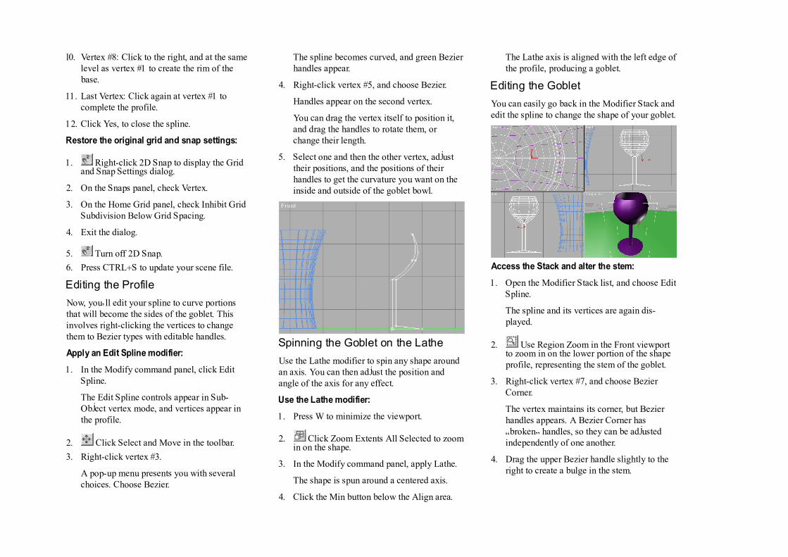
Editing the Profile
Now, you�ll edit your spline to curve portionsthat will become the sides of the goblet. Thisinvolves right-clicking the vertices to changethem to Bezier types with editable handles.
Apply an Edit Spline modifier:
1. In the Modify command panel, click EditSpline.
The Edit Spline controls appear in Sub-Object vertex mode, and vertices appear inthe profile.
2. Click Select and Move in the toolbar.
3. Right-click vertex #3.
A pop-up menu presents you with severalchoices. Choose Bezier.
The spline becomes curved, and green Bezierhandles appear.
4. Right-click vertex #5, and choose Bezier.
Handles appear on the second vertex.
You can drag the vertex itself to position it,and drag the handles to rotate them, orchange their length.
5. Select one and then the other vertex, adjusttheir positions, and the positions of theirhandles to get the curvature you want on theinside and outside of the goblet bowl.
Spinning the Goblet on the Lathe
Use the Lathe modifier to spin any shape aroundan axis. You can then adjust the position andangle of the axis for any effect.
Use the Lathe modifier:
1. Press W to minimize the viewport.
2. Click Zoom Extents All Selected to zoomin on the shape.
3. In the Modify command panel, apply Lathe.
The shape is spun around a centered axis.
4. Click the Min button below the Align area.
The Lathe axis is aligned with the left edge ofthe profile, producing a goblet.
Editing the Goblet
You can easily go back in the Modifier Stack andedit the spline to change the shape of your goblet.
Access the Stack and alter the stem:
1. Open the Modifier Stack list, and choose EditSpline.
The spline and its vertices are again dis-played.
2. Use Region Zoom in the Front viewportto zoom in on the lower portion of the shapeprofile, representing the stem of the goblet.
3. Right-click vertex #7, and choose BezierCorner.
The vertex maintains its corner, but Bezierhandles appears. A Bezier Corner has�broken� handles, so they can be adjustedindependently of one another.
4. Drag the upper Bezier handle slightly to theright to create a bulge in the stem.

5. ][ Press the mouse button over Show EndResult, and then release it.
While the button is down, you see the endresult of the Stack, and the goblet is dis-played.
The goblet now has a decorative stem, but therearen�t enough segments for a smooth roundness.
Increase the segments in the Lathe modifier:
1. Open the Stack, and choose Lathe.
2. Set the Segments spinner to 30.
Name your object, and save your scene:
1. In the name field at the top of the Modifycommand panel, type Goblet.
2. Click Zoom Extents All to view allgeometry in the scene.
3. Use the Select and Move tool to movethe goblet to the narrow end of the table.(Use either the Perspective or the Topviewport to keep it on the table top.)
4. Press CTRL+S to update your scene.
Goblet to Carafe
A carafe would seem a logical companion to agoblet. In 3DS MAX, it�s often as easy to alterexisting objects as it is to create new ones.
Clone the goblet, and edit its spline:
1. Using the Select and Move in Topviewport, hold SHIFT and drag a copy of thegoblet to the center of the table.
2. In the Clone Options dialog, choose Copy,type Carafe in the Name field, and then clickOK.
You now have a copy of the goblet in thecenter of the table.
3. Click Zoom Extents All Selected tozoom in on the new goblet.
4. Open the Stack list in the Modify commandpanel, and choose Edit Spline.
Vertex #7 is still selected from your previoussession with the other goblet. (If it�s not, thenselect it.)
5. Press DEL to delete vertex #7.
6. Right-click vertex #2, and choose Bezier.
7. Right-click vertex #6, and choose Bezier.
8. Adjust the position of the various verticesand their handles to create a profile similar tothat in the following figure.
During the editing process, click Show EndResult ][ regularly to view your progress. Atsome point, you�ll have to zoom out a bit,and move the vertices up so the new profile isalmost twice as tall as the goblet. Note thatyou don�t need to duplicate the carafe in thefigure. Use your imagination.
9. Open the Stack and choose Lathe to return tothe top.
10. Click Zoom Extents All.
Tumbler to Bowl to Lamp
You decide to create a popcorn bowl out of acopy of one of the tumblers. Here�s how to do it.
Clone a tumbler, and make it into a bowl:
1. Select one of the tumblers.
2. Using Select and Move in the Topviewport, hold SHIFT, and move the tumblerin front of the table.
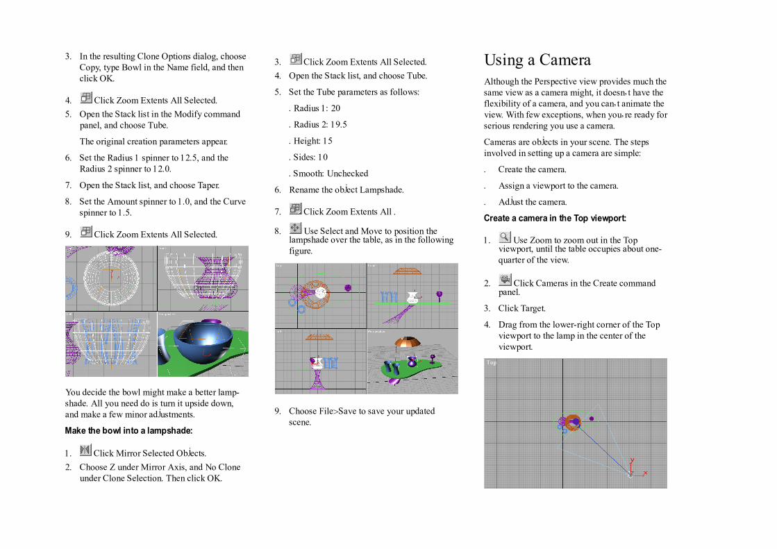
3. In the resulting Clone Options dialog, chooseCopy, type Bowl in the Name field, and thenclick OK.
4. Click Zoom Extents All Selected.
5. Open the Stack list in the Modify commandpanel, and choose Tube.
The original creation parameters appear.
6. Set the Radius 1 spinner to 12.5, and theRadius 2 spinner to 12.0.
7. Open the Stack list, and choose Taper.
8. Set the Amount spinner to 1.0, and the Curvespinner to 1.5.
9. Click Zoom Extents All Selected.
You decide the bowl might make a better lamp-shade. All you need do is turn it upside down,and make a few minor adjustments.
Make the bowl into a lampshade:
1. Click Mirror Selected Objects.
2. Choose Z under Mirror Axis, and No Cloneunder Clone Selection. Then click OK.
3. Click Zoom Extents All Selected.
4. Open the Stack list, and choose Tube.
5. Set the Tube parameters as follows:
· Radius 1: 20
· Radius 2: 19.5
· Height: 15
· Sides: 10
· Smooth: Unchecked
6. Rename the object Lampshade.
7. Click Zoom Extents All .
8. Use Select and Move to position thelampshade over the table, as in the followingfigure.
9. Choose File>Save to save your updatedscene.
Using a CameraAlthough the Perspective view provides much thesame view as a camera might, it doesn�t have theflexibility of a camera, and you can�t animate theview. With few exceptions, when you�re ready forserious rendering you use a camera.
Cameras are objects in your scene. The stepsinvolved in setting up a camera are simple:
· Create the camera.
· Assign a viewport to the camera.
· Adjust the camera.
Create a camera in the Top viewport:
1. Use Zoom to zoom out in the Topviewport, until the table occupies about one-quarter of the view.
2. Click Cameras in the Create commandpanel.
3. Click Target.
4. Drag from the lower-right corner of the Topviewport to the lamp in the center of theviewport.

In the preceding steps, the camera is in the lower-right corner of the viewport, and its target is inthe center of the viewport.
Turn on the Camera viewport:
1. Activate the Perspective viewport.
2. Press C (the keyboard shortcut for camera).
The view changes to that of the cameralooking toward its target.
You can adjust the camera view either by movingthe camera in the scene, or by using the viewportnavigation controls.
Move the camera in the viewports:
1. Click Zoom Extents All.
The orthographic views zoom to extents. Thecamera viewport does not change, becauseZoom Extents All doesn�t affect it.
2. Click Select and Move, and move theselected camera in any of the viewports,rightclicking to cancel each time.
As you move the camera, the view changes inthe camera viewport.
It�s much easier to adjust the camera using theviewport navigation controls. They becomecontrols specific to the camera when you activatethe camera viewport.
Use the camera navigation controls:
1. Activate the camera viewport.
2. Click Truck Camera, and then drag in thecamera viewport to center the objects in theview.
Trucking moves both the camera and itstarget, as if they�re locked. The effect in the
viewport, however, is the same as panning aregular viewport.
3. Click Orbit Camera, and then drag in thecamera viewport to orbit the view sothatyou�re looking down, slightly, on theobjects.
The Orbit Camera function rotates thecamera in an �orbit� about the target. It�ssimilar to the Arc Rotate command.
4. Click Dolly Camera, and drag in theviewport to dolly in on the objects.
When you dolly the camera, you move ittoward or away from its target. The effect issimilar to zooming a regular viewport.
5. Use Truck, Dolly, and Orbit toadjust the camera until you have a viewsimilar to that in the next figure.
A Fast Render
The renderer used by smooth-shaded viewports isdesigned for speed. As a result, it can�t show thesame details with the same accuracy as the 3DSMAX scanline renderer. When you want to see
exactly how your scene will look, take the time torender it.
Render the scene:
1. Make sure the camera viewport is active.
2. Click the Render Scene button.
The Render Scene dialog appears.
3. Make sure Single is chosen.
4. Click the 320x240 button in the OutputSizearea.
5. Click Render.
The scene is rendered.
There are a number of details and effects re-vealed by the scan-line renderer that don�t showin shaded viewports. One of these is the circlecast by a spotlight, as you�ll see in the nextsection.

Setting up LightsWhen there are no lights in your scene (as now),3DS MAX provides a couple of invisible omnilights. One light is positioned in front of thescene, above and to the left, while the second ison the opposite side of the scene, below, to theright, and at the back. As soon as you create alight in your scene, these two lights are turnedoff. If you later delete all the lights in your scene,the two default lights are turned on again.
The default lights are handy when you�re firstputting a scene together, but since you can�tmove them or adjust their color or intensity,you�ll soon want your own lights.
In the following steps, you�ll create and positiona couple of omni lights, and then place a spotlightin the scene.
Omni Lights
An omni light is a point source of light thatshines in all directions. You can�t focus it, and itdoesn�t cast shadows, but you can make it anycolor, and use it for accents and other generallighting effects.
Like cameras, omni lights are objects that usuallydon�t appear in the rendered scene. Instead, yousee the effect of their illumination on the surfacesof the other objects in the scene.
You�ll place two omni lights in your scene, atdiagonally opposing locations.
Set up your viewports:
1. Click the exit button to dismiss therendering window.
2. Activate the Top viewport.
3. Click Zoom All.
4. Drag downward in the Top viewport to zoomout the orthographic viewports until theobjects fill about one-third of the view.
5. Make sure Degradation Overrideis on in the prompt line.
The Degradation Override option, when off,allows the display of geometry in the viewportsto degrade to specified settings (such as box orwireframe) when the viewports can�t redraw fastenough. When you�re positioning lights, how-ever, you want to be able to see their effect onshaded objects, which you can�t if the viewportdegrades to wireframe.
In the next steps, you�ll create the omni lights.You can either click or drag to create an omnilight. If you click, it�s created at that point. If youdrag, you can perform some initial positioningduring the creation process.
Create and position the omni lights:
1. Click Lights in the Create commandpanel.
2. Click Omni.
3. In the Top viewport, in the lower-left quad-rant, drag the mouse to both create andposition an omni light. Release the mousebutton while the omni light is still somewherein the lower-left quadrant.
As soon as you create the first omni light, theshaded camera view grows dark, as thedefault lights are turned off. As you drag thelight, you can see the effect of its movementon the surfaces of the objects in the cameraviewport.
4. Drag in the upper-right quadrant of the Topviewport to create and position a secondomni light. Leave this light in the upper-rightquadrant.
The new light adds to the illumination, butthe table top remains dark because both lightwere created on the ground plane, below thetable.
Position the first light:
· Using Select and Move in the Topviewport, drag the first omni light youcreated to the right until it�s just to the left ofcenter at the bottom of the viewport.
Specular highlights from that light appearalong the front edge of the table top, and atthe left of the items on the table.
Using Place Highlight
You can use the position of the specular high-lights to place your lights by taking advantage ofa toolbar function called Place Highlight.
Use Place Highlight on the second omni:
1. Select the second omni light.
2. Click Place Highlight in the Align flyouton the toolbar.
3. In the camera viewport, drag the mousecontinually over the surface of variousobjects in the scene.
As you drag the mouse, a blue arrow displaysthe face normal of the point under the cursor,and the light moves about the scene to placeits specular highlight at the specified loca-tion.
4. Release the mouse when the specular high-light is over the upper surface and right sideof the carafe.
Note: If you released too soon, simply makesure the light is still selected, click PlaceHighlight, and drag again in the cameraviewport.
5. Click Render Last to render the cameraviewport.
Spotlights
Spotlights provide an adjustable, focused beamof light, and can cast shadows. Creating a target
spotlight is similar to creating a camera. You dragthe mouse to create the spot and its target.
For this scene, you�ll use a spotlight to representthe light coming from the overhead lamp.
Create and adjust a spotlight:
1. Activate the Front viewport.
2. Use Region Zoom to zoom in on the areathat includes the table top and the lampshade.
3. Click Target Spot in the Create commandpanel.
4. In the Front viewport, drag from the top ofthe lampshade, straight down to the top of thetable.
A target spotlight appears in the scene.
The light in the viewport doesn�t change dramati-cally, because there are already two other lightsin the scene, and also because the viewportrenderer uses Gouraud shading, which can�tproperly display the circle of the spotlight.However, you can definitely see the effect in thescanline renderer.
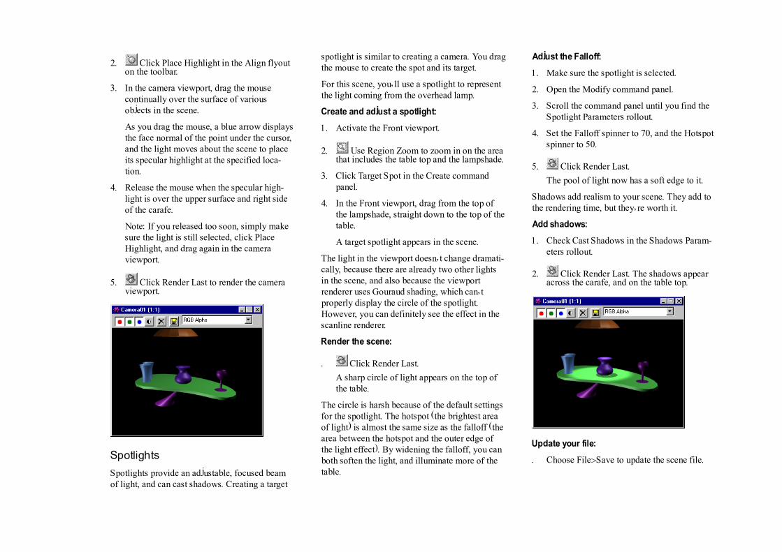
Render the scene:
· Click Render Last.
A sharp circle of light appears on the top ofthe table.
The circle is harsh because of the default settingsfor the spotlight. The hotspot (the brightest areaof light) is almost the same size as the falloff (thearea between the hotspot and the outer edge ofthe light effect). By widening the falloff, you canboth soften the light, and illuminate more of thetable.
Adjust the Falloff:
1. Make sure the spotlight is selected.
2. Open the Modify command panel.
3. Scroll the command panel until you find theSpotlight Parameters rollout.
4. Set the Falloff spinner to 70, and the Hotspotspinner to 50.
5. Click Render Last.
The pool of light now has a soft edge to it.
Shadows add realism to your scene. They add tothe rendering time, but they�re worth it.
Add shadows:
1. Check Cast Shadows in the Shadows Param-eters rollout.
2. Click Render Last. The shadows appearacross the carafe, and on the table top.
Update your file:
· Choose File>Save to update the scene file.

Assigning Materials
Now you will use the Material Editor to make thesurfaces of your objects a little more than justsome randomly assigned colors.
Straighten up the screen:
1. Click Exit to dismiss the renderingwindow.
2. Open the Display command panel, and checkLights and Cameras to hide the lights and thecamera.
3. Click Zoom Extents All.
4. Click Material Editor in the toolbar.
The Material Editor appears.
At the top of the Material Editor are six sampleslots containing sample spheres. You select asample slot by clicking in it. The controls belowthe sample slot affect the sample in the activeslot.
In the following procedure the sample slots arenumbered one through six, beginning with theupper-left slot, and numbering across the top row,and then from left to right across the bottom row.As an example, the middle sample slot on thebottom row is number five.
Carafe-A Dull Clay
You�ll first assign a default material to the carafe,and then adjust its color for a clay-like appear-ance.
Assign a material to the carafe:
1. Select the carafe.
2. The first sample slot should already beselected and bordered by a white outline. Ifit�s not, click in the sample slot to select it.
3. Click Assign Material to Selection (in therow of buttons below the sample slots).
The carafe changes color to match thematerial in the active slot.
Notice the four white triangles in the sample slot.They indicate that this is a hot material. A hotmaterial is one that appears in the scene and isdirectly bound to the material in the sample slot.When you change the settings of a hot material inthe Material Editor, the material changes wher-ever it is in the scene-regardless of the currentselection in the scene.
Materials can get very complex in 3DS MAX.It�s a good idea to always name your materialsrather than relying on the default names.
Name and adjust the material:
1. Type Carafe in the material name field.
The name Carafe also appears in the title barof the Material Editor.
2. Click the color swatch to the right of Diffuse.
The Color Selector appears. Its title tells youthat it represents the Diffuse color.
3. Use the controls in the Color Selector to finda clay-brown color.
The colors change in the sample sphere andon the carafe.
Note: To find a color, drag your mousearound in the large color box. Increase thelevel of the vertical Whiteness ramp toincrease the saturation of the color. Asuggested color might be RGB 160, 120, 80.

4. Set the Shininess spinner to 20.
The sample sphere is not as shiny.
The sample spheres use the scanline renderer,whereas the viewports use the faster Gouraudrenderer. As a result, effects such as shininess arecorrectly represented in the sample slots, but notin the viewport. When adjusting material, alwayswatch the sample sphere, and render your sceneevery so often.
Render the scene:
1. Click Render Last.
The surface of the carafe in the renderedscene is subtly different than the one in theviewport.
2. When the rendering window appears, drag itabove the upper-right viewport, so it willappear there the next time you render.
Goblet-Transparent Plastic
You�ll repeat much the same process with thegoblet, except that you�ll reduce its opacity aswell.
Assign a material to the goblet:
1. Select the goblet.
2. Select the second sample slot.
3. Click Assign Material to Selection.
4. Name the material Goblet.
It�s often easiest to use the same color for boththe diffuse and the ambient properties of amaterial. Briefly, the diffuse is the color that�sreflected in direct light (the large, upper-left areaof the sample sphere), and the ambient is thecolor of the material in shadow (the dark crescentin the lower-left area of the sample sphere) Youlock both colors together, and then adjust eitherproperty.
Lock the Diffuse and Ambient colors:
1. Click the lock button between the Diffuseand Ambient labels, and answer Yes at theprompt.
The two swatches now contain the samecolor.
2. Click the Diffuse or the Ambient colorswatch and choose any color you like.(Suggested: RGB 80, 200, 130.)
As you choose your color, it�s displayed inboth color swatches.
Make the material shinier and transparent:
1. Set the Shininess spinner to 55, and theShininess Strength spinner to 85.
2. Turn on Checkered Background amongthe buttons along the right side of the sampleslots.
3. Set the Opacity spinner to about 50.
The sample sphere becomes transparent, andthe goblet appears dithered and transparent inthe viewport.
4. Click Render Last to see your progress.
The goblet is now transparent and shiny inthe scene.
The transparency in the viewport is a �cheat� thatlets you see the effect of transparency, butmaintains the fast response needed in theviewports. Again, always judge your materials bythe sample slots or the rendered scene.
Table Base-Chrome
For the base of the table, you�ll make a reflec-tion-mapped material.
1. Select the table base.
2. Select the third sample slot.
3. Click Assign Material to Selection.
4. Rename the material Table Base.
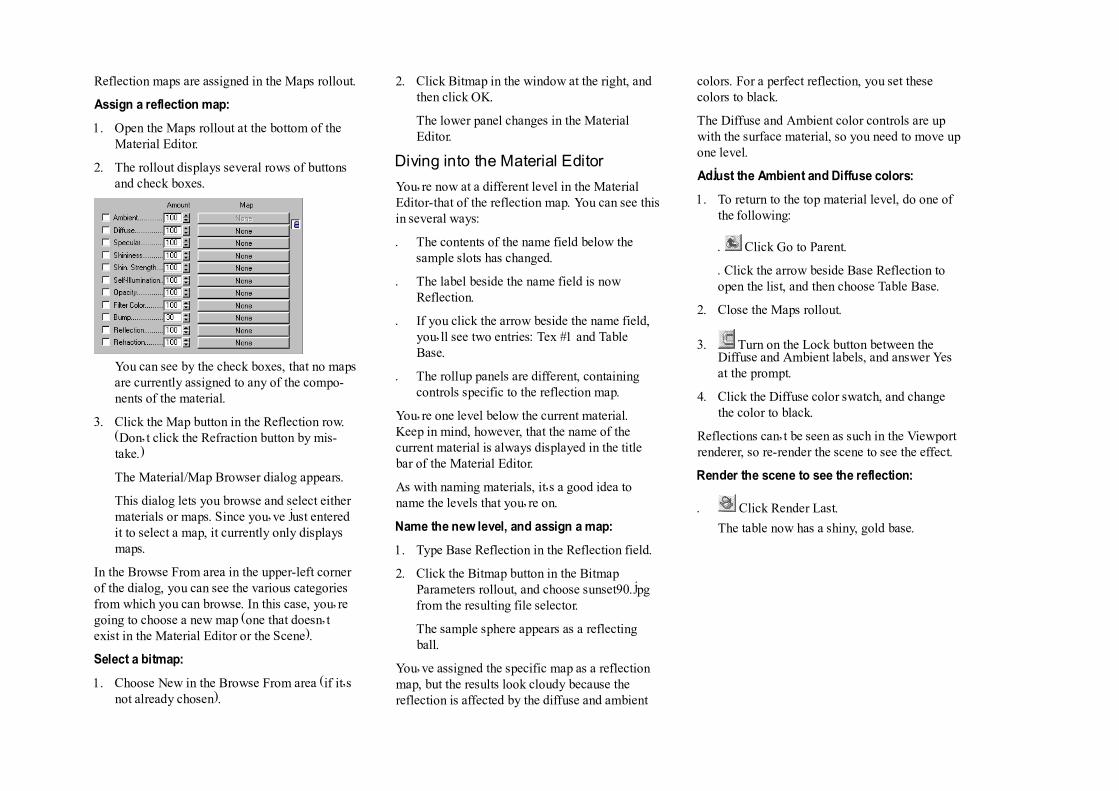
Reflection maps are assigned in the Maps rollout.
Assign a reflection map:
1. Open the Maps rollout at the bottom of theMaterial Editor.
2. The rollout displays several rows of buttonsand check boxes.
You can see by the check boxes, that no mapsare currently assigned to any of the compo-nents of the material.
3. Click the Map button in the Reflection row.(Don�t click the Refraction button by mis-take.)
The Material/Map Browser dialog appears.
This dialog lets you browse and select eithermaterials or maps. Since you�ve just enteredit to select a map, it currently only displaysmaps.
In the Browse From area in the upper-left cornerof the dialog, you can see the various categoriesfrom which you can browse. In this case, you�regoing to choose a new map (one that doesn�texist in the Material Editor or the Scene).
Select a bitmap:
1. Choose New in the Browse From area (if it�snot already chosen).
2. Click Bitmap in the window at the right, andthen click OK.
The lower panel changes in the MaterialEditor.
Diving into the Material Editor
You�re now at a different level in the MaterialEditor-that of the reflection map. You can see thisin several ways:
· The contents of the name field below thesample slots has changed.
· The label beside the name field is nowReflection.
· If you click the arrow beside the name field,you�ll see two entries: Tex #1 and TableBase.
· The rollup panels are different, containingcontrols specific to the reflection map.
You�re one level below the current material.Keep in mind, however, that the name of thecurrent material is always displayed in the titlebar of the Material Editor.
As with naming materials, it�s a good idea toname the levels that you�re on.
Name the new level, and assign a map:
1. Type Base Reflection in the Reflection field.
2. Click the Bitmap button in the BitmapParameters rollout, and choose sunset90.jpgfrom the resulting file selector.
The sample sphere appears as a reflectingball.
You�ve assigned the specific map as a reflectionmap, but the results look cloudy because thereflection is affected by the diffuse and ambient
colors. For a perfect reflection, you set thesecolors to black.
The Diffuse and Ambient color controls are upwith the surface material, so you need to move upone level.
Adjust the Ambient and Diffuse colors:
1. To return to the top material level, do one ofthe following:
· Click Go to Parent.
· Click the arrow beside Base Reflection toopen the list, and then choose Table Base.
2. Close the Maps rollout.
3. Turn on the Lock button between theDiffuse and Ambient labels, and answer Yesat the prompt.
4. Click the Diffuse color swatch, and changethe color to black.
Reflections can�t be seen as such in the Viewportrenderer, so re-render the scene to see the effect.
Render the scene to see the reflection:
· Click Render Last.
The table now has a shiny, gold base.

Tumblers-Choose from the Library
You can store all of the materials you create in amaterial library, and you can create and save anynumber of material libraries. For the two tum-blers, you�ll simply choose a material in theBrowser, after first loading the Tutorial materiallibrary.
Choose a material from the library:
1. Select the two tumblers. (Click to select one,and then press CTRL, and click the othertumbler to add it to the selection.)
2. Select the fourth sample slot.
3. Click Get Material.
The Material/Map Browser appears.
4. Choose Material Library in the Browse Fromarea.
The window now lists all of the material andmaps in the current material library. Thematerials are represented by blue sphereicons, and the maps by green parallelograms.
5. Click Open in the File area, and then loadtutorial.mat \MatLibs directory.
The window list changes to display thematerials from the Tutorial library.
6. Click View Small Icons.
The window at right now displays all materi-als and maps as small spheres or circles. As
you run the mouse over the icons, tooltipsdisplay their names.
7. Click View Large Icons.
The icons fill the screen.
8. Drag the mouse along the right side of thewindow to scroll the view.
9. Find the material labeled Old Gold.
l0. Double-click the Old Gold icon to select it.
The fourth sample slot now contains theselected material.
Assign the material to the goblets:
1. Click Assign Material to Selection.
The goblets are assigned the new material.
2. Click Render Last to see the result.
Table Top-Ash Wood
You�ll assign a diffuse-mapped material to thetable top. A diffuse map is what used to be calleda texture map in 3D Studio for DOS. The termdiffuse map is more accurate, because you�reactually mapping the diffuse (and ambient)portion of the material.
Get and assign the material:
1. Select the table top.
2. Select the fifth sample slot.
3. Click Get Material.
4. Select Ashwood from the material library.
5. Click Assign Material to Selection.
The table top turns blue, because that�s thediffuse color of the material. The map is notcurrently seen.
Because this material uses a diffuse map, youneed to assign mapping coordinates to the tabletop for the renderer to properly place the map.
Display the map in the viewport:
1. Open the Maps rollout.
2. Click the button in the Diffuse row.
The Diffuse level of the material appears, andDiffuse appears beside the name field. Inaddition, the Show Map in Viewport buttonbelow the sample slot is enabled.
3. Turn on the Show Map in Viewportbutton.
The table top turns white, but the mapdoesn�t appear on its surface because nomapping coordinates are assigned to theobject.
4. Open the Modify command panel, and applythe UVW Map modifier.
The woodgrain appears on the table top.
5. Click Render Last.

Lamp-Procedural Checkers
The last object to receive a material is thelampshade. For this, you�ll create your owndiffusemapped material, and you�ll use a proce-dural map.
Create a new material:
1. Select the lamp shade.
2. Select the sixth sample slot.
3. Click Assign Material to Selection.
4. Name the material Lampshade.
In previous steps, you used the Maps rollout toaccess the map levels. There�s a shortcut you canuse for any material component that can use amap. Instead of clicking the button in the Diffuserow of the Maps rollout, you can click the blankmap button beside the Diffuse color swatch.
Assign a diffuse map:
1. Click the blank map button to the right of theDiffuse color swatch.
The Material/Map Browser appears.
2. Choose New, select Checker, and then clickOK.
3. Turn on the Show Map in Viewportbutton.
4. Apply a UVW Map modifier.
The checkers appear on the lampshade.
5. In the Parameters rollout of the Modifycommand panel, set Spherical, and then clickFit.
The woodgrain you used for the table top camefrom a bitmap image of wood. The checkers, onthe other hand, are procedurally generated. As aresult, you can change things, such as the tiling,the angle, the color, and so on.
Adjust the Checker parameters:
1. In the Material Editor, set the U and V Tilingspinners to 10.
2. Set the Angle spinner to 45.
The checkers are now small diamonds on thelampshade.
3. Click the Color #1 swatch. In the ColorSelector, choose any color you like.
4. Click the Color #2 swatch, and chooseanother color you like.
Note: You�ll need to slide the arrow up in theWhiteness ramp of the Color Selector toprovide saturation for the second color.
5. Click Render Last.
The scene appears with all materials as-signed.
Now that you�ve completed your scene, you�lladd some animation. This is a good time to savethe scene.
Save your scene:
· Press CTRL+S to update your scene.

Adding AnimationAnimation can be as obvious as flying logosthrough snowflakes, or it can be as subtle as achange in lighting. To complete the scene, you�llanimate the overhead spotlight so that it bright-ens, and then dims again. To complete theillusion of real light, you�ll also animate one ofthe material properties of the lampshade.
The first step is to turn off the spotlight. You dothis not by actually turning it off, but by settingits color value to black.
Select and turn down the light:
1. Open the Display command panel, anduncheck Lights under Hide by Category.
The spotlight and the omni lights appear.
2. Click Select by Name in the main toolbar.
3. In the Select by Name dialog, click Spot0l,and then click Select.
The spotlight is selected.
4. Open the Modify command panel.
5. In the General Parameters rollout, set theV(alue) spinner to 0.
The spotlight no longer illuminates the table.
Animate the spotlight:
1. Go to frame 50.
2. Turn on the Animate button.
3. Set the V(alue) spinner to 200.
4. In the Material Editor, make sure the Lamp-shade sample slot is active. (Its title shouldappear in the title bar of the Material Editor.)
5. Click Go to Parent to return to the toplevel of the material.
6. Set Self-Illumination to 100.
The sample sphere grows �brighter.�
7. Go to frame 100.
8. Set Self-Illumination to 0.
9. Set the spotlight�s V spinner in the Modifycommand panel to 0.
l0. Turn off the Animate button.
11. Press CTRL+S to save your scene.
You used a combination of two effects to achievethe illusion of translucency in the lampshade.Often, when you work with light in 3D rendering,you need to think through the lighting effects inthe real world, and then use the tools at hand toproduce an illusion of that effect.
Rendering Your AnimationCongratulations! You�ve completed your firstscene. Now it�s time to render an animation.
In the following steps, you�ll render an .avi file ofthe scene. You won�t use the Renderer>MakePreview command, because that uses theviewport renderer, which isn�t accurate enoughfor this scene. Instead, you�ll use the RenderScene command, and output to .avi format.
Render the animation:
1. Click Render Scene.
The Render Scene dialog appears.
2. Choose Active Time Segment in the TimeOutput area.
3. Set 320x240 in the Output Size area.
4. Click Files in the Render Output area, andchoose AVI file under List files of type.
5. Enter a filename, such as mytut2.avi, andthen click OK.
6. Make sure that Save File is checked.
7. Click Render.
8. The scene is rendered, frame by frame.
9. When the rendering is completed, useFile>View File to play your animation.