Major causes of bearing failure Bearings.pdfMajor causes of bearing failure Normal Appearance...
30
6 | © MAHLE 2014 Bearing failures As you know, every automotive engine part will eventually wear out. And if every part always performed for the full length of its expected life, your job would be fairly simple – to replace parts that have worn. Unfortunately, we cannot always count on an engine part failing only because its normal lifespan is exceeded. A technician must not only be a “replacer of parts” but, like a doctor, he must be capable of diagnosing his “patient” to determine why a part failed prematurely. The table below lists the eight major causes of premature engine bearing failure, along with percentage figures which indicate how often each has been found to be the prime contributor to a bearing’s premature failure. However, it is important to note that in many cases a premature bearing failure is due to a combination of several of these causes. MAJOR CAUSES OF PREMATURE BEARING FAILURE Dirt 45.4% Misassembly 12.8% Misalignment 12.6% Insufficient Lubrication 11.4% Overloading 8.1% Corrosion 3.7% Improper Journal Finish 3.2% Other 2.8% Thus we can reason that if a technician merely replaces a damaged bearing in an engine, without determining the cause of its failure, more than 99% of the time he will be subjecting the replacement bearing to the same cause that was responsible for the original failure. What this all means is that just as a doctor cannot cure a patient until he has determined what ails him, so, too, a technician cannot correct the cause of premature bearing failure until he first determines what causes the failure. Each failure is organized, for your convenience, into four major subjects: 1. Appearance – an illustration and brief description of a bearing that has failed due to a specific cause. 2. Damaging Action – what actually damaged the bearing under the conditions which were present. 3. Possible Causes – a listing of those factors capable of creating the particular damaging action. 4. Corrective Action – the action that should be taken to correct the cause of failure. Covered here, are the most common failure types. Please refer to the Bearing Distress Guide located at www.mahle-aftermarket.com as a reference to help you in properly determining the cause of premature bearing failures. Major causes of bearing failure Normal Appearance Uniform wear pattern over approximately 2/3 of the bearing’s surface. Wear should diminish near the parting line ends of the bearing and the wear pattern should extend uniformly across the bearing in the axial direction.
-
Upload
phamnguyet -
Category
Documents
-
view
219 -
download
3
Transcript of Major causes of bearing failure Bearings.pdfMajor causes of bearing failure Normal Appearance...

6 | © MAHle 2014
Bearing failures
As you know, every automotive engine part will eventually wear out. And if every part always performed for the full length of its expected life, your job would be fairly simple – to replace parts that have worn. Unfortunately, we cannot always count on an engine part failing only because its normal lifespan is exceeded. A technician must not only be a “replacer of parts” but, like a doctor, he must be capable of diagnosing his “patient” to determine why a part failed prematurely. The table below lists the eight major causes of premature engine bearing failure, along with percentage figures which indicate how often each has been found to be the prime contributor to a bearing’s premature failure. However, it is important to note that in many cases a premature bearing failure is due to a combination of several of these causes.
MAJOR CAUSES OF PREMATURE BEARING FAILURE
Dirt 45.4%
Misassembly 12.8%
Misalignment 12.6%
Insufficient lubrication 11.4%
Overloading 8.1%
Corrosion 3.7%
Improper Journal Finish 3.2%
Other 2.8%
Thus we can reason that if a technician merely replaces a damaged bearing in an engine, without determining the cause of its failure, more than 99% of the time he will be subjecting the replacement bearing to the same cause that was responsible for the original failure. What this all means is that just as a doctor cannot cure a patient until he has determined what ails him, so, too, a technician cannot correct the cause of premature bearing failure until he first determines what causes the failure.
each failure is organized, for your convenience, into four major subjects:
1. Appearance – an illustration and brief description of a bearing that has failed due to a specific cause.
2. Damaging Action – what actually damaged the bearing under the conditions which were present.
3. Possible Causes – a listing of those factors capable of creating the particular damaging action.
4. Corrective Action – the action that should be taken to correct the cause of failure.
Covered here, are the most common failure types. Please refer to the Bearing Distress Guide located at www.mahle-aftermarket.com as a reference to help you in properly determining the cause of premature bearing failures.
Major causes of bearing failure
Normal Appearance
Uniform wear pattern over approximately 2/3 of the bearing’s surface. Wear should diminish near the parting line ends of the bearing and the wear pattern should extend uniformly across the bearing in the axial direction.

© MAHle 2014 | 7
Foreign particles in lining
APPEARANCEForeign particles are embedded in the lining of the bearing. Scratch marks may also be visible on the bearing surface.
DAMAGING ACTIONDust, dirt, abrasives and/or metallic particles, present in the oil supply, embed in the soft babbitt bearing lining, displacing metal and creating a high-spot.
The high-spot may be large enough to make contact with the journal causing a rubbing action that can lead to the eventual breakdown and rupture of the bearing lining. Foreign particles may embed only partially and the protruding portion may come in contact with the journal and cause a grinding wheel action.
POSSIBLE CAUSES1. Improper cleaning of the engine and/or parts
prior to assembly. 2. Road dirt and sand entering the engine
through the air-intake manifold or faulty air filtration.
3. Wear of other engine parts, resulting in small fragments of these parts entering the engine’s oil supply.
4. Neglected oil filter and/or air filter replacement.
CORRECTIVE ACTION1. Inspect journal surfaced and regrind if
excesssive wear is discovered. 2. Install new bearings, following proper
cleaning procedures.3. Recommend that the operator have the oil,
air filter, oil filter and crankcase breather-filter replaced as recommended by the manufacturer.
Bearing lining
Bearing backOil clearance Dirt particle
JournalDisplaced bearing
metal

8 | © MAHle 2014
Bearing failures
Foreign particles on bearing back
APPEARANCEA localized area of wear can be seen on the bearing surface. Also, evidence of foreign particle(s) may be visible on the bearing back or bearing housing directly behind the area of surface wear.
DAMAGING ACTIONForeign particles between the bearing and its housing prevent the entire area of the bearing back from being in contact with the housing base. As a result, the transfer of heat away from the bearing surface is not uniform causing localized heating of the bearing surface which reduces the life of the bearing.
Also, an uneven distribution of the load causes an abnormally high pressure area on the bearing surface, increasing localized wear on this material.
POSSIBLE CAUSESDirt, dust abrasives and/or metallic particles either present in the engine at the time of assembly or created by a burr removal operation can become lodged between the bearing back and bearing housing during engine operation.
CORRECTIVE ACTION1. Inspect journal surfaced and regrind if
excesssive wear is discovered. 2. Install new bearings following proper clean-
ing and burr removal procedures.
Housing
Shaft
Bearing
END VIEW SIDE VIEW
Foreign particle

© MAHle 2014 | 9
Misassembly
engine bearings will not function properly if they are installed incorrectly. In many cases, misassembly will result in premature failure of the bearing.
The following are typical assembly errors most often made in the installation of engine bearings.
2
4
REVERSEDCORRECT
Position of Offset Connecting Rod Reversed
Bearing Caps in Wrong or Reversed Position
Bearing Halves Reversed Bearing Oil Hole Not Aligned With Oil Passage Hole
Improper Shim Installation
Locating Lugs Not Nested
Oil hole in bearing
Oil hole in bearing
Oil passage holein crankcase
10 | © MAHle 2014
Bearing failures
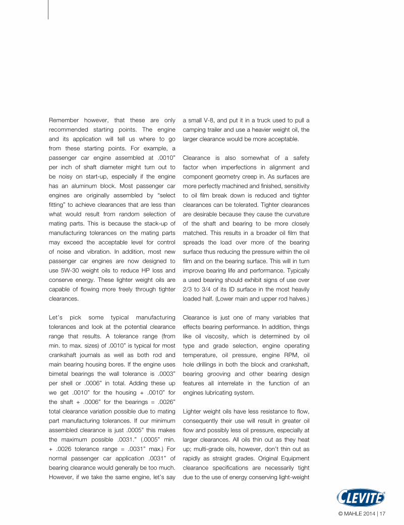
Overlay fatigue
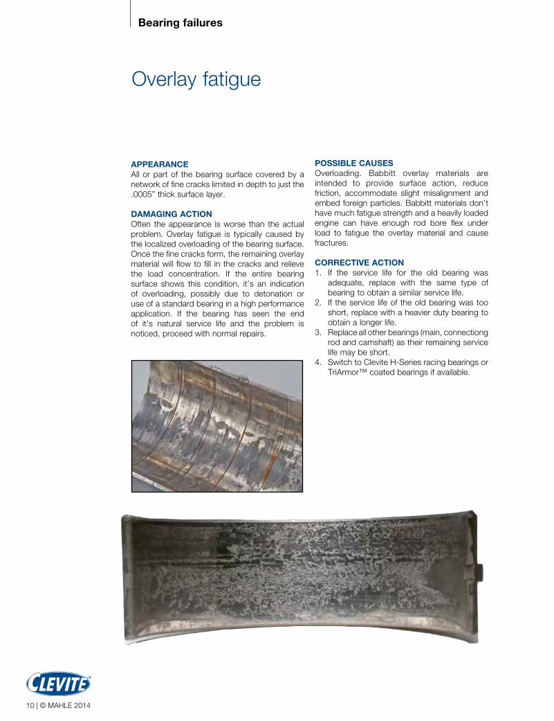
APPEARANCEAll or part of the bearing surface covered by a network of fine cracks limited in depth to just the .0005” thick surface layer.
DAMAGING ACTIONOften the appearance is worse than the actual problem. Overlay fatigue is typically caused by the localized overloading of the bearing surface. Once the fine cracks form, the remaining overlay material will flow to fill in the cracks and relieve the load concentration. If the entire bearing surface shows this condition, it’s an indication of overloading, possibly due to detonation or use of a standard bearing in a high performance application. If the bearing has seen the end of it’s natural service life and the problem is noticed, proceed with normal repairs.
POSSIBLE CAUSESOverloading. Babbitt overlay materials are intended to provide surface action, reduce friction, accommodate slight misalignment and embed foreign particles. Babbitt materials don’t have much fatigue strength and a heavily loaded engine can have enough rod bore flex under load to fatigue the overlay material and cause fractures.
CORRECTIVE ACTION1. If the service life for the old bearing was
adequate, replace with the same type of bearing to obtain a similar service life.
2. If the service life of the old bearing was too short, replace with a heavier duty bearing to obtain a longer life.
3. Replace all other bearings (main, connectiong rod and camshaft) as their remaining service life may be short.
4. Switch to Clevite H-Series racing bearings or TriArmor™ coated bearings if available.

© MAHle 2014 | 11
excessive crush
APPEARANCEBearing may have localized polishing or wear near the parting lines or adjacent to an oil hole. Contact frequently appears in an “X” shape pattern when at an oil hole.
DAMAGING ACTIONBearing wall increased in thickness due to upset (yielding) of the steel back. This causes localized shaft contact with resulting polishing and wear.
POSSIBLE CAUSESBearings are designed to be a slight interference fit in their housing bore. Bearing “crush”, which is designed into the bearing, controls this. Installing a bearing in an undersize housing hole increases crush and will cause the steel back to yield and get thicker at the point of least resistance. This is generally at an oil hole or adjacent to the parting lines if there is no hole.
CORRECTIVE ACTION1. Verify that the bearing installed was correct
for the application.2. Inspect housing for correct size within
manufacturers limits and resize as required.3. All Clevite high performance, as well as many
standard passenger car and heavy duty diesel bearings are designed with maximum crush to provide the greatest amount of retention. Never try to reduce clearance by installing a bearing in a housing smaller than the minimum size specified.
Excessive crush

12 | © MAHle 2014
Bearing failures
Bent or twisted connecting rod
APPEARANCEBent rods will exhibit heavy wear on diagonally opposite sides of each shell, typically in an edge-loaded pattern. Twisted rods will exhibit wear running diagonally across the bearing surface.
DAMAGING ACTIONA bent or twisted connecting rod results in misalignment of the bore, causing the bearing to be cocked so the bearing edge makes metal-to-metal contact with the journal which can cause excessive wear on the bearing surface.
POSSIBLE CAUSESThe most common cause of a bent rod is a previous engine failure such as a blown head gasket, allowing the cylinder to fill with coolant or a dropped valve causing a piston and rod to go under extreme load, resulting in rod deformation.
A twist is most likely introduced during the manufacturing or reconditioning process if upper and lower bores are not maintained parallel.
CORRECTIVE ACTION1. Bent and twisted rods must not be re-used
but either repaired or replaced. Re-use will result in the same failure.
2. Install new bearings, following proper cleaning procedures.Front main
bearing
True crankcase center line
Bent crankcase center line

© MAHle 2014 | 13
Oil starvation / marginal oil film
APPEARANCEThis failure is very common, but difficult to diagnose, especially for a person not seeing many bearing failures. The reason is the progression from early stage scratching from the journal surface penetrating the oil film and contacting the bearing, to ultimate failure (hot short) which may occur quickly and all inside the engine. Distress generally starts at the center of the bearing and progresses toward the outer edges.
DAMAGING ACTIONThe absence of a sufficient oil film between the bearing and the journal allows for metal-to-metal contact. The resulting wiping action causes premature bearing failure.
POSSIBLE CAUSES1. Too little bearing oil clearance 2. Too much bearing clearance combined with
heavy loads3. Amount, quality and viscosity of the oil4. Oil delivery or oil pressure issues5. Misassembled parts blocking off oil holes6. Dry start / no pre-lube7. High cylinder pressure causing reduced oil
film thickness
CORRECTIVE ACTION1. Double-check all measurements taken during
the bearing selection procedure to catch any errors in calculation. This can be done during assembly with Clevite Plastigage®
2. Check to be sure that the replacement bearing is the correct one for the application.
3. Check the journals for damage and regrind if necessary.
4. Check the engine for possible blockage of oil passages, oil suction screen and oil filter.
5. Check the operation of the oil pump and pressure relief valve.
6. Be sure that the oil holes are properly indexed when installing the replacement bearings.
7. Make sure the oil quality, additive base and viscosity is correct for the application.
8. Always prime the lubrication system before the engine is started for the first time.
9. Install new bearings, following proper cleaning procedures.

The exclusive Clevite® TriArmor™ engine
bearings feature a .0003” thick dry film coating
on the bearing surface providing extraordinary
protection and lubricity. enhanced wear
characteristics increase bearing life in race
engines and high performance street engines.
Now, high performance engine builders can
enjoy the strength and durability of the legendary
Clevite® TriMetal™ bearing construction coupled
with the latest in coating technology - right out
of the box.
The line of Clevite® TriArmor™ rod and main
bearings include popular Ford, GM and Chrysler
models as well as popular Sport Compact
applications.
Exclusive Dry Film Treatment
For years, engine builders have experimented
with coating engine bearings for race engines
and high performance street engines, with
varying degrees of success. Now, MAHle
engineers, after extensive research and
development, have devised TriArmor™, a
proprietary dry film coating.
Central to this breakthrough is the exclusive dry
film and unique application and low temperature
cure processes. These processes provide
extremely uniform thickness coupled with
unparalleled adhesion, all while protecting the
metallurgical integrity of the bearing during the
coating procedure.
The result? A .0003” thick protective coating
that offers:
n Reduced friction and drag, resulting in
increased horsepower
n Protection during start-up
n embedability to resist damage from debris
n Ability to withstand extreme temperatures and
pressures
n Conformability for distressed or imperfect
surfaces
n extraordinary strength and durability
14 | © MAHle 2014
TriArmor™
Coated bearings
Precisionsteel back
Dry filmcoating
Babbitt alloy layer
Cast copper-lead alloy layer

We’re particular about parting linesAt MAHLE Aftermarket, we know that bearing crush is critical, especially in high performance engines. So you can imagine that coating the part-ing lines would adversely affect bearing crush and fit. And you shouldn’t have to sand off material that never should have been applied to these surfaces in the first place. So we don’t put it there. It’s extra effort to do the job right, but that’s the only way MAHLE engineers know how.
© MAHle 2014 | 15
Tech Info
In developing TriArmor™ materials and
processing, MAHle engineers relied on the
science of tribology, the study of design,
friction, wear, and lubrication characteristics
of interacting surfaces. With our existing body
of knowledge based on decades of producing
bearings for street and track, this model enabled
us to offer the most advanced and efficient
coating material possible. The material gives
good low load start-up protection. The coating
serves as a high pressure, high load dry film anti-
wear agent. It also provides additional protection
across a broad range of temperatures, especially
when oil flow is marginal and is especially
slippery with an oil film.
Exclusive Clevite TriArmor™ Features
� Coverage for Ford, GM and Chrysler as well
as popular Sport Compact Applications
� Parting lines not coated
� legendary Clevite quality
Coated bearing features & benefits
Feature Advantage Benefit
Dry Film Coating low friction Reduces drag & increases HPDry Film Coating Self-lubricating Helps fight dry startsDry Film Coating High strength Good support for oil filmDry Film Coating Resists wear Fights unfavorable surface finishesDry Film Coating Not temperature sensitive Protects hot or coldRated for 500 F 1 Resists breakdown Welcomes tough racing applicationsRated for 600 F 2 extra margin Defends against severe conditionsLow Temp Cure Bearing friendly Protects metallurgical integrity of bearingInert Wear Layer Conformability Adapts as needed to the “real engine”OEM Caliber processes Superior quality Tightest controls of thickness and curing tempsBare Parting Line No sanding needed Proper crush without “reworking” bearing1 Continuous 2 Intermittent

16 | © mahle 2014
how much clearance do your bearings need?
how much clearance do I need for my rod,
main or camshaft bearings? This is one of the
most frequently asked questions. Unfortunately,
there isn’t one simple answer that suits every
case. engine application, lubricant selection
and operating conditions will dictate different
clearance levels. This isn’t to say we can’t
generalize on at least a starting point.
First, let’s define how and where clearance
should be measured. half shell rod and main
bearings do not have a uniform wall. The wall
is thickest at 90 degrees from the split and
drops off a prescribed amount toward each
parting line, depending on the bearings intended
application. This drop off is called “eccentricity.”
In addition, there is a relief at the parting lines.
eccentricity is used to tailor the bearing shell to
its mating hardware and to provide for hardware
deflections in operation. eccentricity also helps
to promote oil film formation by providing a
wedge shape in the clearance space. The relief
at each parting line insures that there will not be
a step at the split line due to bearing cap shift
or the mating of bearing shells that differ slightly
in thickness within allowed tolerance limits. (See
figure 1.)
For these reasons, bearing clearances are
specified as “vertical clearance” and must be
measured at 90 degrees to the split line. The
best method of measurement is with a dial bore
gage that measures the bearing inside diameter
when the bearings are installed at the specified
torque without the shaft in place. measurements
should be taken at front, center and rear of
each bearing position. another common method
of checking clearance is through the use of
Clevite® Plastigage®. (See figure 2.)
For most applications .00075 to .0010” (three
quarters to one thousandth of an inch) of
clearance per inch of shaft diameter is a
reasonable starting point. For example a 2.000”
shaft diameter would require .0015 to .0020”
bearing clearance. (.00075 X 2.000” = .0015”
and .0010 X 2.000” = .0020”) Using this formula
will provide a safe starting point for most
applications. For high performance engines it
is recommended that .0005” be added to
the maximum value determined by the above
calculation. The recommendation for our 2.000”
shaft would be .0025” of clearance.
Centerlinewall
Bearinghalfshells
Eccentricity = amount of changein wall at this point,from centerline
Parting line
Parting linerelief
JOURNAL
1/4" 3/8"
Figure 1
Bearing clearance
Figure 2
© mahle 2014 | 17
Remember however, that these are only
recommended starting points. The engine
and its application will tell us where to go
from these starting points. For example, a
passenger car engine assembled at .0010”
per inch of shaft diameter might turn out to
be noisy on start-up, especially if the engine
has an aluminum block. most passenger car
engines are originally assembled by “select
fitting” to achieve clearances that are less than
what would result from random selection of
mating parts. This is because the stack-up of
manufacturing tolerances on the mating parts
may exceed the acceptable level for control
of noise and vibration. In addition, most new
passenger car engines are now designed to
use 5W-30 weight oils to reduce hP loss and
conserve energy. These lighter weight oils are
capable of flowing more freely through tighter
clearances.
let’s pick some typical manufacturing
tolerances and look at the potential clearance
range that results. a tolerance range (from
min. to max. sizes) of .0010” is typical for most
crankshaft journals as well as both rod and
main bearing housing bores. If the engine uses
bimetal bearings the wall tolerance is .0003”
per shell or .0006” in total. adding these up
we get .0010” for the housing + .0010” for
the shaft + .0006” for the bearings = .0026”
total clearance variation possible due to mating
part manufacturing tolerances. If our minimum
assembled clearance is just .0005” this makes
the maximum possible .0031.” (.0005” min.
+ .0026 tolerance range = .0031” max.) For
normal passenger car application .0031” of
bearing clearance would generally be too much.
however, if we take the same engine, let’s say
a small V-8, and put it in a truck used to pull a
camping trailer and use a heavier weight oil, the
larger clearance would be more acceptable.
Clearance is also somewhat of a safety
factor when imperfections in alignment and
component geometry creep in. as surfaces are
more perfectly machined and finished, sensitivity
to oil film break down is reduced and tighter
clearances can be tolerated. Tighter clearances
are desirable because they cause the curvature
of the shaft and bearing to be more closely
matched. This results in a broader oil film that
spreads the load over more of the bearing
surface thus reducing the pressure within the oil
film and on the bearing surface. This will in turn
improve bearing life and performance. Typically
a used bearing should exhibit signs of use over
2/3 to 3/4 of its ID surface in the most heavily
loaded half. (lower main and upper rod halves.)
Clearance is just one of many variables that
effects bearing performance. In addition, things
like oil viscosity, which is determined by oil
type and grade selection, engine operating
temperature, oil pressure, engine RPm, oil
hole drillings in both the block and crankshaft,
bearing grooving and other bearing design
features all interrelate in the function of an
engines lubricating system.
lighter weight oils have less resistance to flow,
consequently their use will result in greater oil
flow and possibly less oil pressure, especially at
larger clearances. all oils thin out as they heat
up; multi-grade oils, however, don’t thin out as
rapidly as straight grades. Original equipment
clearance specifications are necessarily tight
due to the use of energy conserving light-weight

18 | © mahle 2014
oils, relatively high operating temperatures and
a concern for control of noise and vibration,
especially in aluminum blocks.
high performance engines on the other hand,
typically employ greater bearing clearances for a
number of reasons. Their higher operating speeds
result in considerably higher oil temperatures
and an accompanying loss in oil viscosity due to
fluid film friction that increases with shaft speed.
Increased clearance provides less sensitivity to
shaft, block and connecting rod deflections and
the resulting misalignments that result from the
higher levels of loading in these engines. Use of
synthetic oils with their better flow properties can
help to reduce fluid film friction.
Friction and horsepower loss are prime concerns
in high performance engines for obvious reasons.
as a result, the coating of various engine
components with friction reducing compounds
has become common practice. Clevite offers
Triarmor™ coated bearings for selected high
Performance applications. Clevite wants to
provide high performance engine builders with
Clevite® performance series bearings already
coated with a friction reducing surface treatment.
Use of these coated bearings may result in
slightly less clearance than the uncoated Clevite®
high performance parts for the same application.
This will typically be in the range of .0005.” This
is because the coating, although expected to
remain in place during service, is considered to
be somewhat of a sacrificial layer. Some amount
of the coating will be removed during break-in
and operation resulting in a slight increase in
clearance. This is the reason no adjustment in
bearing machining dimensions was made to
allow for coating application.
Bearing clearance is not a subject that can
be addressed without taking into account
numerous variables including; geometry of the
parts, oil viscosity, oil temperature, engine load,
shaft diameter, bearing coatings and one’s own
ability to accurately measure and assess these
variables.
FLANGE THICKNESS
UNDERCUT
PARTING LINE HEIGHT
THRUST FACE RELIEF
THRUST FACE
FLANGE DIAM
ETER
OIL HOLE
OIL SPREADER GROOVE
LOCATING LUG
OIL GROOVE
OIL POCKET
THRUST FACE GROOVE
CHAMFER
BETWEEN FLANGE LENGTH
LENGTH - SHOWN AS "MAX. LENGTH" IN CATALOG SHOP DATA
PARTING LINE
CROWN AREA
INSIDE DIAMETER
OUTSIDE DIAMETER - SHOWN AS "BEARING O.D."
IN CATALOG SHOP DATA
Bearing clearance

© mahle 2014 | 19
Various forms of main bearing grooving have
been used over the years. We are frequently
asked what difference grooving makes.
First, it’s essential to understand that bearings
depend on a film of oil to keep them separated
from the shaft surface. This oil film is developed
by shaft rotation. as the shaft rotates it pulls oil
into the loaded area of the bearing and rides up
on this film much like a tire hydroplaning on wet
pavement. Grooving in a bearing acts like tread
in a tire to break up the oil film. While you want
your tires to grip the road, you don’t want your
bearings to grip the shaft.
The primary reason for having any grooving in a
main bearing is to provide oil to the connecting
rods. Without rod bearings to feed, a simple
oil hole would be sufficient to lubricate a main
bearing. many early engines used full grooved
bearings and some even used multiple grooves.
as engine and bearing technology developed,
bearing grooving was removed from modern
lower main bearings. The result is in a thicker
film of oil for the shaft to ride on. This provides a
greater safety margin and improved bearing life.
Upper main shells, which see lower loads than
the lowers, have retained a groove to supply the
connecting rods with oil.
In an effort to develop the best possible main
bearing designs for performance engines, we’ve
investigated the effects of main bearing grooving
on bearing performance. The graphs illustrate
that a simple 180 degree groove in the upper
main shell is still the best overall design.
While a slightly shorter groove of 140 degrees
provides a marginal gain, most of the benefit
is to the upper shell, which doesn’t need
improvement. On the other hand, extending
the groove into the lower half, even as little as
20 degrees at each parting line (220 degrees
in total), takes away from upper bearing
performance without providing any benefit to
the lower half. It’s also interesting to note that as
groove length increases so do horsepower loss
and peak oil film pressure which is transmitted
directly to the bearing.
Influence of grooving on main bearing performance
Main bearing grooving

20 | © mahle 2014
Main bearing grooving

© mahle 2014 | 21
Crankshaft grinding and polishing
Crankshaft journal surfaces should be ground
and polished to a surface finish of 15 micro
inches roughness average Ra or better. Journals
on highly loaded crankshafts such as diesel
engines or high performance racing engines
require a finish of 10 micro inches Ra or better.
The above is a simple straight forward
specification which can be measured with special
equipment. however, there is more to generating
a ground and polished surface than just meeting
the roughness specification. To prevent rapid,
premature wear of the crankshaft bearings
and to aid in the formation of an oil film, journal
surfaces must be ground opposite to engine
rotation and polished in the direction of rotation.
This recommendation can cause a great deal
of confusion in actual execution. Understanding
the reasons behind the recommendation and
examination of the following illustrations will help
make the recommendation more clear.
metal removal tends to raise burrs. This is
true of nearly all metal removal processes.
Different processes create different types of
burrs. Grinding and polishing produces burrs
that are so small that we can’t see or feel them
but they are there and can damage bearings if
the shaft surface is not generated in the proper
way. Rather than “burrs,” let’s call what results
from grinding and polishing “microscopic fuzz.”
This better describes what is left by these
processes. This microscopic fuzz has a grain
or lay to it like the hair on a dog’s back. Figure
1 is an illustration depicting the lay of this fuzz
on a journal. (Note: all figures are viewed from
nose end of crankshaft.) The direction in which
a grinding wheel or polishing belt passes over
the journal surface will determine the lay of the
micro fuzz.
In order to remove this fuzz from the surface,
each successive operation should pass over
the journal in the opposite direction so that the
fuzz will be bent over backward and removed.
Polishing in the same direction as grinding would
not effectively remove this fuzz because it would
merely lay down and then spring up again.
Polishing must, therefore, be done opposite to
grinding in order to improve the surface.
In order to arrive at how a shaft should be
ground and polished, we must first determine
the desired end result and then work backwards
to establish how to achieve it. Figure 2 depicts
a shaft turning in a bearing viewed from the
front of a normal clockwise rotating engine.
The desired condition is a journal with any fuzz
left by the polishing operation oriented so it will
lay down as the shaft passes over the bearing
(Figure 2).
Fuzz
Figure 1Journal illustrating fuzz from grinding and polishing.
Figure 2Journal rotating in bearing with the grain of the fuzz.
Bearing
Crankshaft grinding

22 | © mahle 2014
The analogy to the shaft passing over the
bearing is like petting a dog from head to tail. a
shaft polished in the opposite direction produces
abrasion to the bearing which would be like
petting a dog from tail to head. To generate
a surface lay like that shown in Figure 2, the
polishing belt must pass over the shaft surface
as shown in Figure 3.
The direction of shaft rotation during polishing
is not critical if a motorized belt type polisher is
used because the belt runs much faster than the
shaft. Stock removal during polishing must not
exceed .0002” on the diameter.
having determined the desired surface lay from
polishing, we must next establish the proper
direction for grinding to produce a surface
lay opposite to that resulting from polishing.
Figure 4 shows the grinding wheel and shaft
directions of rotation and surface lay for grinding
when viewed from the front or nose end of the
crankshaft. This orientation will be achieved by
chucking the flywheel flange at the left side of
the grinder (in the headstock). achieving the
best possible surface finish during grinding will
reduce the stock removal necessary during
polishing.
The surface lay generated by grinding would
cause abrasion to the bearing surfaces if left
unpolished. By polishing in the direction shown
in figure 3, the surface lay is reversed by the
polishing operation removing fuzz created by
grinding and leaving a surface lay which will not
abrade the bearing surface.
Nodular cast iron shafts are particularly difficult
to grind and polish because of the structure of
the iron. Nodular iron gets its name from the
nodular form of the graphite in this material.
Grinding opens graphite nodules located at
the surface of the journal leaving ragged edges
which will damage a bearing. Polishing in the
proper direction will remove the ragged edges
from these open nodules.
all of the above is based on normal clockwise
engine rotation when viewed from the front
of the engine. For crankshafts which rotate
counterclockwise, such as some marine engines,
the crankshaft should be chucked at its opposite
end during grinding and polishing. This is the
same as viewing the crank from the flanged end
rather than the nose end in the accompanying
figures.
Polis
hing
Bel
t
Figure 3Direction polishing belt should pass over journaland grain of fuzz which results.
Grinding Wheel
Figure 4Directions of shaft and grinding wheel rotation and lay of fuzz which results.
Crankshaft grinding

© mahle 2014 | 23
Severe use recommendations
Crankshaft surface finish and shape are key
factors affecting the performance of all bearings.
These factors become even more critical for
thrust surfaces. as in any bearing, increased
loading reduces oil film thickness between shaft
and bearing surfaces. This is a much more
critical situation in thrust bearings due to their
flat faces which make formation of an oil film
extremely difficult. Radial bearings (those which
carry loads in a radial direction like rod and main
bearings) form a natural wedge where shaft and
bearing surfaces come together in the clearance
space. Shaft rotation pulls a wedge of oil into the
loaded area of the bearing and forms an oil film
that supports the load.
Thrust faces, on the other hand, are made up
of two flat surfaces that do not form a natural
wedge where they meet. In order to help form
an oil film, artificial wedge shaped areas are
machined into the bearing surfaces at the ends
and sometimes adjacent to the grooves. In spite
of all the common design efforts, thrust bearings
still run on a much thinner film of oil that makes
crankshaft surface finish critical in the successful
performance of these bearings.
Recent samples of thrust face surface finish
on crankshafts from blown fuel “hemi” engines
have confirmed that better finishes resulted
in a reduced rate of bearing distress. The
study also showed that when no damage
occurred, the crankshaft surface finish was
improved after running. The surface finishes of
12 crankshafts were measured (7 new and 5
used). The new shafts ranged from a high of
30 Ra to a low of 5 Ra. The used shafts had a
very similar range from 31Ra to 4 Ra. although
this represents only a small sampling, it does
demonstrate a correlation between surface finish
and performance when the condition of mating
bearing surfaces was evaluated. Prior to these
measurements, race experience had shown
no problems on a crankshaft with a thrust-face
Ra of 6 and did show problems on crankshafts
when the Ra was over 20.
Obtaining a good finish on the thrust face of
a crankshaft is difficult to do because it uses
side-wheel grinding. Side grinding causes marks
that spiral outward toward the OD of the thrust
face and may also cause crosshatch marks
resembling honing patterns. Both patterns
are detrimental to the formation of an oil film
because they work like wipers as the shaft
rotates. Grinding marks must be removed by
polishing. Only a circular pattern should remain.
Surface finish should be checked in a tangential
direction and must be held to 10 Ra max. The
thrust surface should be flat within .0002” max.
avoid - crosshatch pattern
avoid - swirl pattern
Bearing recommendations

24 | © mahle 2014
Selecting high performance bearings
Pointers for selecting high performance rod and main bearings
Just like Fords differ from Chevrolets and
Chryslers, the various specialty parts for
these engines also differ from one specialty
manufacturer to another. This is not to say that
any one brand of connecting rod, for example, is
necessarily better than another, they just exhibit
different characteristics.
Background
all bearings are an interference fit in their
housing; this relates to something we call crush.
Crush results from each half shell bearing being
made a few thousandths more than a true half
circle. When two bearing shells are placed
together their outside diameter is slightly larger
than the ID of the housing they fit into. When
the housing cap is torqued the bearings are
compressed, like a spring, resulting in a radial
contact pressure between the bearings and the
housing. another way of looking at it is that the
housing is squeezing inward on the bearings and
the bearings are pushing back outward against
the housing. most of the interference fit is
taken up by the bearings but the outward force
exerted by the bearings against the housing
also causes slight changes in the size and
shape of the housing. This is called “housing
Bore Distortion” or just ‘Bore Distortion”. With
these factors in mind, it’s easy to understand
why housings made of different materials like
aluminum versus iron or steel will have different
amounts of “Bore Distortion”.
Compensating for differing amounts of bore
distortion isn’t as simple as just making an
adjustment in the bearing clearance when the
engine is assembled. The reason is that most
housings (connecting rods and engine blocks)
have irregular shapes surrounding the bearing.
Rods, for example, have a beam at the top,
notches for bolt heads or nuts, some have ribs
over the cap while others don’t and of course,
the parting line between the rod and cap is a
weak point. The result is that bore distortions
are seldom ever uniform in all directions. Some
housings go out of round with the greatest
dimension in the horizontal direction while others
grow more in the vertical. Still others may bulge
where there’s a notch for bolt head clearance.
all of these bore distortion characteristics relate
to the static loads between the bearings and
housing when the engine is not running. Still
another consideration is what happens under the
dynamic conditions of a running engine where
loads are constantly changing in magnitude and
direction. engine loads placed on the bearings
and their housings will result in still further
changes in housing bore geometry.
Original equipment bearings are tailored to
compensate for the combined static and
dynamic distortions which occur in the housings.
Specialty high performance parts like connecting
rods and aluminum blocks are made for lighter
weight and to withstand the higher loads and
speeds of high performance engines. They
seldom ever duplicate the bore distortion
characteristics of the original equipment parts.
Taking these facts into account, it should come
as no surprise then that standard passenger car
bearings are not suitable for engines modified
extensively to produce higher horsepower and
speeds. This not only explains why we have
special bearings for high performance, but also
why we offer several choices.
With so many different specialty high performance
connecting rods and blocks available its

© mahle 2014 | 25
impossible for the bearing manufacturer to know
the characteristics of every piece. even if we did,
the choices of related parts which influence such
things as rotating and reciprocating weights
and balancing, all effect bearing loads and
consequently dynamic bore distortions.
Bearing Design
So just how are bearings tailored to compensate
for bore distortions? To understand this important
design concern, we must first determine what
the most desirable shape for a bearing ID is.
If everything remained constant like loading,
speeds and housing geometry, a perfectly round
bearing could be made to work very well. For
example, electric motor bushings run almost
indefinitely under these conditions. In an engine
where we have the variables described above, it
has been determined that a slightly oval bearing
ID with the minimum diameter oriented in line
with the maximum load is the most desirable. To
produce this type of profile, bearings are made
with what we call an eccentric wall. In nearly all
cases the bearing wall is thickest at 90 degrees
to the parting line and tapers off from that point
toward each parting line by some specified
amount.
The amount of change, called eccentricity,
is tailored to suit the bore displacement
characteristics of the housing. a housing
which experiences its greatest distortion in the
horizontal direction (across the parting line)
provides the desired oval shape so the bearing
requires a minimum amount of eccentricity. If the
housing experiences its maximum distortion in
the vertical direction, a high eccentricity bearing
is needed to compensate for this and produce
the desired maximum ovality in the horizontal
direction.
Connecting rods are subjected to high inertia
loads at the top of the exhaust stroke when
the weight of the piston, rings, wrist pin and
top end of the rod are all pulling on the rod
cap. This loading tries to stretch the rod and
pulls the big end out of round, causing it
to close in across the parting line. In this
case, bearing wall eccentricity provides extra
clearance to let the rod flex without
having the bearings contact the
shaft. Besides low, medium and
high eccentricity, Clevite high
performance bearings are offered
with numerous additional features
to make them compatible with
related parts and suitable for the
loads and speeds of competition
engines.
Centerlinewall
Bearinghalfshells
Eccentricity = amount of changein wall at this point,from centerline
Parting line
Parting linerelief
JOURNAL
1/4" 3/8"

26 | © mahle 2014
h-Series Bearings
These bearings are identified by a letter h or
hN in the part number suffix. Part numbering is
based on the same core number as the standard
passenger car parts for the same application.
These bearings were developed primarily for use
in NaSCaR type racing, but are suitable for all
types of competition engines.
h-Series bearings have a medium level of
eccentricity, high crush, and rod bearings
have a hardened steel back and thin overlay.
These bearings also have enlarged chamfers
for greater crankshaft fillet clearance and are
made without flash plating for better seating.
Bearings with .001” extra clearance are available
for standard size shafts and carry the suffix
Precision wall tolerance ± .00015” with strong, extra-thin overlays to withstand high loading and resist flaking.
High crush for better seating and retention.
Medium eccentricity.
Unplated hardened steel backing for
better dimensional accuracy and bore
contact.
hX (X = extra clearance). Rod bearings are
available with or without dowel holes (hD = with,
h = without), main bearings are available with
standard 180 degrees upper half grooving and
with full 360 degrees grooving (h = 180 degrees,
hG = 360 degrees). Use h-Series bearings
with crankshafts that have oversize fillets and
where engines run in the medium to high RPm
range. h-Series bearings should be used if
contact patterns obtained with P-Series parts
are too narrow. Contact patterns should ideally
cover 2/3 to 3/4 of the bearing surface. See
accompanying contact pattern diagrams. If you
aren’t sure which type of performance bearing
to start with, the h-Series bearing will be your
best choice.
Please note: Some “H” series bearings will no longer be available with enlarged chamfers. Instead, the bearings will be narrowed in place of the enlarged chamfer to provide greater crankshaft fillet clearance. The new narrowed bearings will be available with a “HN” suffix and will be replacing the standard “H” suffix part number.
Series bearings

© mahle 2014 | 27
These bearings are identified by a letter K in the
part number suffix. Part numbering is based on
the same core number as the high performance
part and will service the same application.
These bearings were developed primarily for
high performance applications and all types of
competition engines. K-Series bearings have
a proprietary .0003” dry film treatment applied
to the bearings surface, but not the bearing
parting lines. The dry film coating gives good
K-Series Bearings
proprietary TriArmor™coating
bare parting lines
low load start-up protection. The coating serves
as a high pressure, high load dry film anti-wear
agent providing additional protection across the
broad range of temperatures, especially when
oil flow is marginal and is especially slippery
with an oil film. These bearings, which are also
referred to as Triarmor™, still offer the strength
and durability of the legendary Clevite Trimetal™
bearing construction coupled with the latest in
coating technology.
Narrow wear pattern Wide wear pattern Ideal wear pattern
Too much eccentricity.Use the H-Series to correct this.
Too little eccentricity.Use the P-Series to correct this.
The wear pattern should cover 2/3 - 3/4 of the bearing surface area.

28 | © mahle 2014
V-Series bearings
These parts essentially duplicate the former
Vandervell parts under the Clevite part
numbering system. (Same core part no. as
standard passenger car parts but with a suffix
letter “V”).
V-Series rod bearings typically have low to
medium eccentricity and a hardened steel
back. all V-Series main sets use a single piece
thrust bearing rather than the former Vandervell
assembled type of construction. V-Series parts
are not available with oversize chamfers. extra
clearance parts are available with a suffix VX
(.001” extra clearance), and VXX (.002” extra
clearance) for some applications. V-Series
bearings do not have flash plating on the
steel back. Narrowed parts are available with
a VN suffix for some applications. These are
High crush for better seating and retention.
Low to Medium eccentricity.
Unplated hardened steel backing for
better dimensional accuracy and bore
contact.
Lead-indium overlay for improved comformability.
made to accommodate increased crankshaft
fillet clearance.
The chief difference between the V-Series and
other Clevite® Trimetal™ bearings is the use of
a lead-indium overlay. Use V-Series bearings if
prior experience has shown a preference for the
lead-indium type of overlay. lead-indium overlay
offers somewhat better conformability than lead-
tin-copper overlay with slightly reduced wear
resistance.
Some V-Series bearings also feature our Tri-
Bore design. Tri-Bore bearings have a tapered
face from the centerline of the bearing and
were developed primarily for nitro engines to
accommodate high crankshaft deflection.
Series bearings

© mahle 2014 | 29
m-Series bearings
Clevite® “micro” bearings make up the m-series.
These are special purpose bearings having a
nominal .006” thick babbitt lining on a hardened
steel back. m-Series rod bearings have been
slightly narrowed at one end to provide extra
fillet clearance without the need of a large
chamfer. The lower rod shells have a dowel
hole for use in aluminum rods with dowel pins.
m-Series mains have enlarged chamfers and,
for certain applications, oil holes and oil grooves
have also been enlarged.
Use m-series parts to take advantage of the
high degree of conformability offered by the
babbitt lining. These parts are intended mainly
for engines where severe crankshaft deflections
cause edge loading of the bearings. Under these
operating conditions bearing service life will be
very short.
Frequent inspections are recommended and
bearings should be replaced at the first signs of
distress.
High crush for better seating and retention.
Hardened steel backing on selected
parts to resist extrusion under
load.
Wide oil grooves on main bearing accommodate
more oil.
Micro-thin Babbitt for surface properties and
tolerance for shaft deflection.

30 | © mahle 2014
When measuring bearings, measurements
should always be taken at 90 degrees to the
parting line to determine the minimum clearance.
If measuring the bearing wall thickness, use a
special micrometer with a ball anvil to fit the
curvature of the bearing ID. The best way to
determine bearing clearance is to measure the
bearing ID with the bearings installed in the
housing and the bolts torqued to the specified
assembly torque. Use a dial bore gage to
measure the bearing ID at 90 degrees to the
parting line, then subtract shaft size from bearing
ID to determine clearance. If the dial bore
gage is zeroed at the actual diameter of the
crankshaft journal to be installed, the dial bore
gage will then read clearance directly and the
subtraction calculation can be eliminated. about
.001” clearance per inch of shaft diameter is
a good rule of thumb for clearance. Increasing
the total by about .0005” will add a little margin
of safety when starting out, especially for rods.
example: .001” X 2.100 = .0021” then add
.0005”, so starting out set clearance at .0026”
for a 2.100 shaft.
If clearance adjustments need to be made, use
either an extra clearance part for more clearance,
or an undersize part for less clearance. It is
permissible to mix sizes if less than .001”
adjustment in clearance is desired. When mixing
sizes for select fitting never mix parts having
more than .0005” difference in wall size, and
always install the thickest wall shell in the
upper position if installing a rod bearing, or the
lower position if installing a main bearing. When
working with a reground shaft always measure
assembled bearing IDs first and have the shaft
sized to produce the desired clearance since
there are no extra clearance parts available for
undersize shafts.
When measuring a bearing ID or wall thickness
avoid measuring at the parting line. as the
“Bearing Design” diagram illustrates there is a
parting line relief machined into nearly all bearing
shells. This relief is to allow for any mis-match
between upper and lower shells due to tolerance
differences, or possibly resulting from cap shift
or twist during assembly. To determine bearing
wall eccentricity or assembled bearing ID ovality,
measure at a point at least 3/8” away from the
parting line.
When installing any bearing DO NOT aTTemPT
TO POlISh The BeaRING RUNNING SURFaCe
WITh aNY TYPe OF aBRaSIVe PaD OR PaPeR.
Bearing overlay layers are extremely soft and
thin, typically .0005” on high performance parts.
These thin layers can easily be damaged or
removed by abrasive media. Because the overlay
layer is electroplated, it may exhibit microscopic
plating nodules that make it feel slightly rough.
The nodules are the same material as the rest
of the plated layer and will quickly be flattened
by the shaft. Bearing surfaces can be lightly
burnished with solvent and a paper towel if
desired.
arriving at the correct choice of high performance
bearing for a given racing application is much
like determining what clearance works best.
We use past experience, our knowledge of the
intended usage, and common sense to guide
us in making an initial choice. From there on we
can fine tune the selection process based on
Installation and fitting tips
Bearing installation and fitting

© mahle 2014 | 31
P-Series H-Series V-Series M-Series
Rods Mains Rods Mains Rods Mains Rods Mains
Eccentricity h h-m m m l-m l-m l-m-h l-m
High Crush X X X X X X X X
Hard Back X X X X
O.S. Chamfers X X aS S X
Dowel Hole a a a X
Thin Overlay X X X
No Flash a a X X X X X X
Plating
Reduced Wall X X X X
Tolerance
Full Grooving a a a a
Legend:
A = Available for some applicationsH = High eccentricity (up to .0015”)L = Low eccentricity (up to .0005”)M = Medium eccentricity (up to .0010”)S = Shortened length at fillet endX = Applies to all or nearly all parts
results. The information given here is intended
to aid in the initial selection as well as the fine
tuning process.
The following table serves as a brief overview
of the features included in each of the special
Clevite® brand high performance bearing series.

32 | © mahle 2014
Prefixes
CB . . . . . . . . .Connecting Rod Bearing
SH . . . . . . . . .Camshaft Bearing Set
SH . . . . . . . . . Individual Camshaft Bearing
SM . . . . . . . . .Connecting Rod or main Bearing Shim Set
TW . . . . . . . . .Thrust Washer Set
MS . . . . . . . . .main Bearing Set
MB . . . . . . . . . Individual main Bearing
223. . . . . . . . .Piston Pin Bushing
Suffixes
DBearing has dowel hole.
Hhigh performance bearing (on main sets this indicates partial groove).
HGhigh performance full annular grooved bearing.
HThigh performance with indentless locating lug. “Full Bore” design.
Khigh performance bearing with proprietary Triarmor™ coating applied to the bearing surface.
MSteel backed bearings with a micro-Babbitt lining. Precision undersizes are not resizable (material designation B-2).
xx xxxx xx (F)
Core Number(Denotes specific individual
application)
Indicates flanged bearing
Part Number Identification
Nhigh performance bearing narrowed for greater crankshaft fillet clearance.
Vhigh performance bearing with a lead-indium overlay (on main sets this indicates partial groove).
VGhigh performance bearing with a lead-indium overlay and a full annular groove.
xBearing has .001” more oil clearance than standard.
xxBearing has .002” more oil clearance than standard.
WIndicates a part that is a thrust washer (may also be designated upper or lower).
Part number identification

© mahle 2014 | 33
Bearing Outside Diameter Or Housing BoreThe minimum to maximum diameter of the hole in the engine block or the connecting rod.
CrushWhen the bearing half is in its place in the housing bore, there is a slight bit of material that extends above the housing bore. When the assembly is torqued to proper specification, force is then exerting onto the OD of the bearing causing a press fit. Crush also aids in bore distortion, and heat transfer by increasing the surface contact with the bearing and the bore. Clevite Performance bearings have added crush for heat transfer and bearing retention. The amount of crush will vary depending on application.
Eccentricitya gradual reduction in the bearing wall thickness start-ing at the crown and ending at approximately .380” from the parting lines.
Full Annular GroovedBearings having an oil groove cut from parting line to parting line in the internal surface of the half shell. When two grooved halves are joined, this creates a groove in the internal surface around the total circum-ference of the bearing.
B-1Steel backed tin or lead base conventional babbitt (nominal .020” thickness).
B-2Steel backed tin or lead base with a micro-Babbitt lining (nominal .006” thickness).
TM-77Steel backed bearings with an intermediate layer of copper-lead alloy and an electro-plated lead-base overlay. Precision undersizes are not resizable.
TM-112Steel backed bearings with an intermediate layer of copper-lead alloy and an electro-plated lead-base overlay. Precision undersizes are not resizable.
Maximum Bearing LengthThe maximum length that the bearing may have (in-cluding the flange when it applies). The actual length is usually less than this value.
Maximum Wall At CrownThe maximum thickness of the bearing wall at 90° from the parting lines. The actual thickness is usually
less than this value.
Standard Shaft DiameterThe minimum to maximum size of the standard main crankshaft journal, connecting rod journal or camshaft
journal.
Vertical Oil ClearanceThe difference between the assembled inside diameter of the bearing and the outside diameter of the shaft, measured at 90° from the bearing parting lines.
Bearing material Designations & Terminology
VP-2Steel backed bearings with an intermediate layer of copper-lead alloy and an electroplated lead indium overlay. Not resizable.
VP-3Steel backed bearings with an intermediate layer of copper-lead alloy and an extra thick electroplated lead indium overlay. Not resizable.
Material designations and terminology

34 | © mahle 2014
OIL SPREADER GROOVE
LOCATING LUG
OIL GROOVE
OIL POCKET
THRUST FACE GROOVE
CHAMFER
BETWEEN FLANGE LENGTH
LENGTH - SHOWN AS "MAX. LENGTH" IN CATALOG SHOP DATA
PARTING LINE
CROWN AREA
INSIDE DIAMETER
OUTSIDE DIAMETER - SHOWN AS "BEARING O.D."
IN CATALOG SHOP DATA
FLANGE THICKNESS
UNDERCUT
PARTING LINE HEIGHT
THRUST FACE RELIEF
THRUST FACE
FLANGE DIAM
ETER
OIL HOLE
Bearing Nomenclature
Bearing nomenclature

© mahle 2014 | 35
Crankshaft Designs and Bearing locations
Crankshaft Designs
Bearing Locations
Three main bearing - 4 cylinder Seven main bearing - 6 cylinder
Five main bearing - 4 cylinder Four main bearing - v6
Four main bearing - 6 cylinder Five main bearing - v8
Crankshaft designs and bearing locations