Maintenance y - Material Handling Solutions | Hytrol ... REMUEVA ESTA SE A L DE LA MAQUINA NUNCA.....
36
Model 25-LREZ Effective April 2008 (Supercedes January 2001) Bulletin # 603 Installation and Maintenance Manual with Safety Information and Parts List RECOMMENDED SPARE PARTS HIGHLIGHTED IN GRAY IMPORTANT! DO NOT DESTROY HYTROL CONVEYOR CO., INC. © COPYRIGHT 2008–HYTROL CONVEYOR CO., INC. Jonesboro, Arkansas ¡IMPORTANTE! NO DESTRUIR Manual de Instalación y Mantenimiento con Información sobre Seguridad y Lista de Partes LAS PARTES DE REPUESTO RECOMENDADAS SE RESALTAN EN GRIS TM
Transcript of Maintenance y - Material Handling Solutions | Hytrol ... REMUEVA ESTA SE A L DE LA MAQUINA NUNCA.....

Model 25-LREZEffective April 2008(Supercedes January 2001)
Bulletin # 603
Installationand
MaintenanceManual
with Safety Informationand Parts List
RECOMMENDED SPARE PARTS HIGHLIGHTED IN GRAY
IMPORTANT!DO NOT DESTROY
HYTROL CONVEYOR CO., INC.© COPYRIGHT 2008–HYTROL CONVEYOR CO., INC.
Jonesboro, Arkansas
¡IMPORTANTE!NO DESTRUIR
Manualde Instalación
yMantenimientocon Información sobre Seguridad
y Lista de PartesLAS PARTES DE REPUESTO RECOMENDADAS SE RESALTAN EN GRIS
TM

2
l Table of Contents l Tabla de ContenidoWarning Signs . . . . . . . . . . . . . . . . . . . . .3
INTRODUCTIONReceiving and Uncrating . . . . . . . . . . . . .4
INSTALLATIONInstallation Safety Precautions . . . . . . . .5Support Installation . . . . . . . . . . . . . . . . .6Conveyor Set-Up . . . . . . . . . . . . . . . . . . .7Electrical Equipment . . . . . . . . . . . . . . . .9
OPERATIONOperation Safety Precautions . . . . . . . .11Conveyor Start-Up . . . . . . . . . . . . . . . . .11Belt Installation . . . . . . . . . . . . . . . . . . .12Belt Tracking . . . . . . . . . . . . . . . . . . . . .13Sequence of Operation . . . . . . . . . . . . .15EZLogic® System . . . . . . . . . . . . . . . . . .16Loading & Unloading Applications . . . .18Pressure Frame Adjustment . . . . . . . . .22
MAINTENANCEMaintenance Safety Precautions . . . . .24Lubrication . . . . . . . . . . . . . . . . . . . . . . .25Drive Chain Alignment and Tension . . .26Trouble Shooting . . . . . . . . . . . . . . . . . .27Maintenance Checklist . . . . . . . . . . . . .29
REPLACEMENT PARTSHow To Order Replacement Parts . . . .2925-LREZ Parts Drawing . . . . . . . . . . . .3025-LREZ Parts List . . . . . . . . . . . . . . . .31Pneumatic Parts Drawing . . . . . . . . . . .32Pneumatic Parts List . . . . . . . . . . . . . . .33
Señales de Advertencia . . . . . . . . . . . . .3
INTRODUCCIONRecepción y Desembalaje . . . . . . . . . . .4
INSTALACIONSeguridad en la Instalación . . . . . . . . . . .5Instalación de los Soportes . . . . . . . . . . .6Montaje . . . . . . . . . . . . . . . . . . . . . . . . . .8Equipo Eléctrico . . . . . . . . . . . . . . . . . .10
OPERACIONInstalación de la Banda . . . . . . . . . . . . 12Alineación de la Banda . . . . . . . . . . . .13Secuencia de Operación . . . . . . . . . . . 15Sistema EZLogic . . . . . . . . . . . . . . . . . 16Aplicaciones de Carga y Descarga . . . .18Ajuste de la Placa de Presión . . . . . . . 22
MANTENIMIENTOSeguridad en el Mantenimiento . . . . . .13Lubricación . . . . . . . . . . . . . . . . . . . . . .13Tensión y Alineación . . . . . . . . . . . . . . 26 Resolviendo Problemas . . . . . . . . . . . .28Lista de Mantenimiento Preventivo . . . .29
PARTES DE REPUESTOComo Ordenar Partes de Repuesto . . .29Dibujo de Partes del 25-LREZ . . . . . . .30Lista de Partes del 25-LREZ . . . . . . . . .31Dibujo de las Partes Neumáticas . . . . .32Lista de Partes Neumáticas . . . . . . . . .33

3
In an effort to reduce the possibility of injury to personnelworking around HYTROL conveying equipment, warningsigns are placed at various points on the equipment to alertthem of potential dangers. Please check equipment andnote all warning signs. Make certain your personnel arealerted to and obey these warnings. Shown below are typi-cal signs that are attached to this equipment.
En un esfuerzo por reducir la posibilidad de accidentes alpersonal trabajando junto al equipo de transportaciónHYTROL, se colocan señales de advertencia en diferentespuntos del equipo para alertarlos de riesgos potenciales.Por favor verifique el equipo y asegúrese de ver todas lasseñales de advertencia. Asegúrese de que su personal estéalerta y obedezca las señales. Abajo se muestran lasseñales que se encuentran en este equipo.
l Warning Signs l Señales de Advertencia
PLACED ON ALL POWERED CONVEYORSNEAR DRIVE AND/OR CONTROLS.
PLACED NEXT TO DRIVE, BOTH SIDES. PLACED ON 20 FT. INTERVALS,BOTH SIDES.
PLACED AT DRIVE OF ALL POWERED CONVEYORS.
PLACED ON TERMINATING ENDS.
COLOCADA EN TODOS LOSTRANSPORTADORES MOTORIZADOS
CERCA AL MOTOR Y/O LOS CONTROLES
COLOCADA EN LA UNIDAD MOTRIZ DE TODOS LOSTRANSPORTADORES MOTORIZADOS.
COLOCADA EN INTERVALOS DE 20 PIES, A AMBOS LADOS.
COLOCADA EN LOS EXTREMOS.
COLOCADA JUNTO A LA UNIDAD MOTRIZ, ENAMBOS LADOS.
DANGERClimbing, sitting,walking or riding onconveyor at any timewill cause severeinjury or death
KEEP OFF
WARNINGExposed movingparts can causesevere injury
LOCK OUT POWERbefore removing guard
WARNINGServicing moving or energized equipmentcan cause severe injury
LOCK OUT POWERbefore removing guard
WARNINGMoving equipment can cause severeinjury
KEEP AWAY
WARNING!DO NOT START CONVEYOR
UNTIL PERSONNEL ARE CLEAR
WARNING
DO NOT REMOVE THIS SIGN FROM THIS MACHINE
NEVER... START CONVEYOR UNTIL PERSONNEL ARE CLEAR
NEVER... LUBRICATE OR REPAIR WHILE CONVEYOR IS RUNNING
NEVER... RUN THE CONVEYOR WITH GUARDS REMOVED
NEVER...NEVER... ALLOW ANY PART OF YOUR BODY TO COME IN CONTACT WITH THE CONVEYOR PULLEYS WHILE IT IS RUNNING.
IT IS THE EMPLOYERS RESPONSIBILITY TO IMPLEMENT THE ABOVE ANDALSO TO PROVIDE ADEQUATE PROTECTION FOR ANY PARTICULAR USE,OPERATION OR SERVICE.
PUT YOUR HANDS ON THE CONVEYOR OR IN THECONVEYOR WHEN IT IS RUNNING.
PLACED ON ALL CHAIN GUARDS.COLOCADA EN TODAS LAS GUARDA CADENAS.
PELIGRO! ?
CONSERVE DISTANCIA
Subirse, sentarse, caminar o viajaren el transportadoren cualquier momento,puede causar lesionesgraves o incluso la muerte.
Partes expuestas enmovimento puedencausar lesiones graves.
ADVERTENCIA!
DESCONECTAR la energia antes deremover la guarda.
ADVERTENCIA!El mantenimiento de partes eléctricas o en movimiento puedecausar lesiones graves.
DESCONECTAR la energiaantes de remover la guarda.
ADVERTENCIA!Partes en movimientopueden causarlesiones graves.
NO SE ACERQUE
¡ADVERTENCIA!NO PONER EN MARCHA EL TRANSPORTADOR
HASTA QUE TODO EL PERSONAL ESTE ALEJADO
ADVERTENCIA
NO REMUEVA ESTA SEÑAL DE LA MAQUINA
NUNCA.. ARRANCAR EL TRANSPORTADOR HASTA QUE TODO EL PERSONAL ESTE ALEJADO
NUNCA.. LUBRICAR O REPARAR MIENTRAS EL TRANSPORTADOR ESTE EN FUNCIONAMIENTO
NUNCA.. HACER FUNCIONAR EL TRANSPORTADOR CON LAS GUARDAS REMOVIDAS
NUNCA..NUNCA.. PERMITIR QUE ALGUNA PARTE DEL CUERPO ESTE EN CONTACTO CON LAS POLEAS DEL TRANSPORTADOR MIENTRAS ESTE EN FUNCIONAMIENTO
ES RESPONSABILIDAD DE LOS SUPERVISORES IMPLEMENTAR LAS SEÑALESANTERIORES Y TAMBIEN PROVEER LA ADECUADA PROTECCION PARACUALQUIER USO, OPERACION O SERVICIO PARTICULAR.
COLOCAR LAS MANOS SOBRE O DENTRO DEL TRANSPORTADORCUANDO ESTE EN FUNCIONAMIENTO
NOTE: BILINGUAL (SPANISH) LABELS AVAILABLE UPON REQUEST.NOTA: ETIQUETAS BILINGÜES (ESPAÑOL) SERÁN PROVEÍDAS
BAJO PETICIÓN.

4
This manual provides guidelines and procedures forinstalling, operating, and maintaining your conveyor. A com-plete parts list is provided with recommended spare partshighlighted in gray. Important safety information is also pro-vided throughout the manual. For safety to personnel andfor proper operation of your conveyor, it is recommendedthat you read and follow the instructions provided in thismanual.
Check the number of items received against the bill oflading.Examine condition of equipment to determine if anydamage occurred during shipment.Move all crates to area of installation.Remove crating and check for optional equipmentthat may be fastened to the conveyor. Make surethese parts (or any foreign pieces) are removed.
Este manual provee las pautas y los procedimientos parainstalar, operar y mantener su transportador. Se propor-ciona una lista completa de partes, con partes de repuestorecomendadas que se resaltan en gris. También se propor-ciona información importante de seguridad a lo largo deeste manual. Para seguridad del personal y para un fun-cionamiento apropiado del transportador, se recomiendaque lean y sigan las instrucciones proporcionadas en estemanual.
1. . .
2. . .
3. . .4. . .
Verifique el número de partes recibidas con respectoal conocimiento de embarque.Examine las condiciones del equipo con el fin dedeterminar si algún daño ha ocurrido durante eltransporte.Traslade todo el equipo al área de instalación.Remueva todos los empaques y verifique si haypartes opcionales que puedan estar atadas alequipo. Asegúrese de que estas partes (u otraspartes externas) sean removidas.
1. . .
2. . .
3. . .4. . .
NOTE: If damage has occurred or freight is missing, seethe “Important Notice” attached to the crate.
NOTA: Si algún daño ha ocurrido o falta cargamento,vea las “Notas Importantes” adheridas al embalaje.
INTRODUCTION INTRODUCCION
l Receiving andUncrating
l Recepción yDesembalaje
5
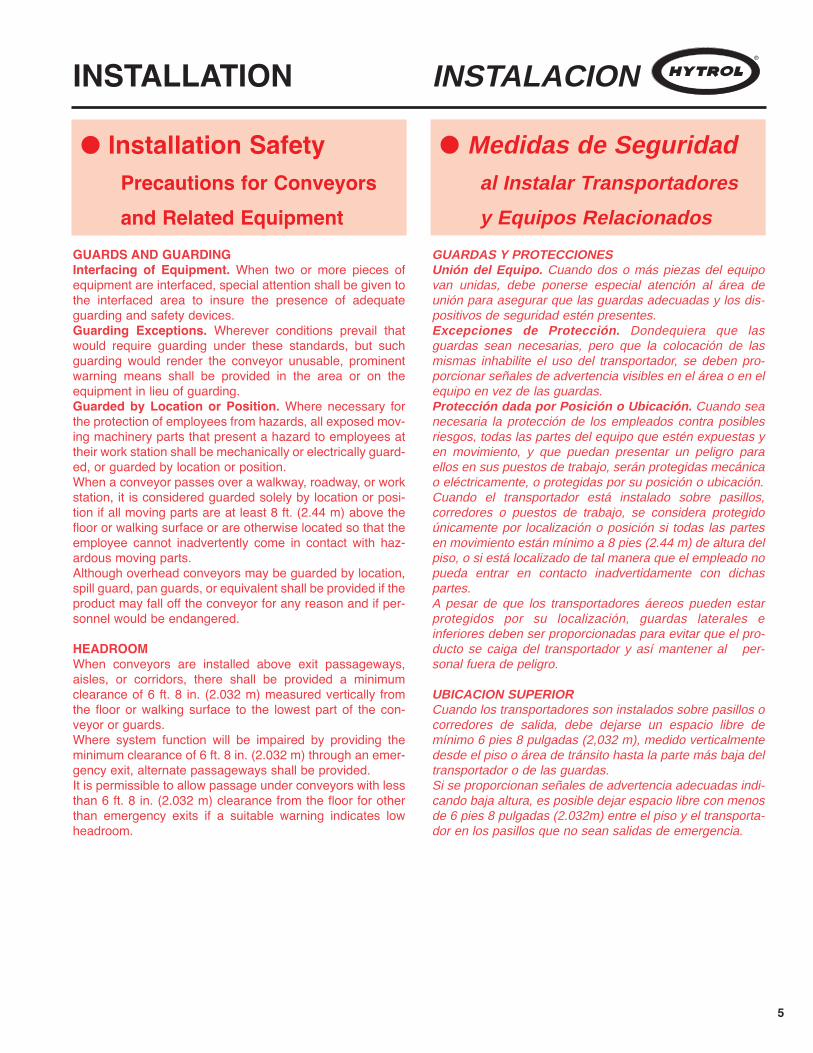
GUARDS AND GUARDINGInterfacing of Equipment. When two or more pieces ofequipment are interfaced, special attention shall be given tothe interfaced area to insure the presence of adequateguarding and safety devices.Guarding Exceptions. Wherever conditions prevail thatwould require guarding under these standards, but suchguarding would render the conveyor unusable, prominentwarning means shall be provided in the area or on theequipment in lieu of guarding.Guarded by Location or Position. Where necessary forthe protection of employees from hazards, all exposed mov-ing machinery parts that present a hazard to employees attheir work station shall be mechanically or electrically guard-ed, or guarded by location or position.When a conveyor passes over a walkway, roadway, or workstation, it is considered guarded solely by location or posi-tion if all moving parts are at least 8 ft. (2.44 m) above thefloor or walking surface or are otherwise located so that theemployee cannot inadvertently come in contact with haz-ardous moving parts.Although overhead conveyors may be guarded by location,spill guard, pan guards, or equivalent shall be provided if theproduct may fall off the conveyor for any reason and if per-sonnel would be endangered.
HEADROOMWhen conveyors are installed above exit passageways,aisles, or corridors, there shall be provided a minimumclearance of 6 ft. 8 in. (2.032 m) measured vertically fromthe floor or walking surface to the lowest part of the con-veyor or guards.Where system function will be impaired by providing theminimum clearance of 6 ft. 8 in. (2.032 m) through an emer-gency exit, alternate passageways shall be provided.It is permissible to allow passage under conveyors with lessthan 6 ft. 8 in. (2.032 m) clearance from the floor for otherthan emergency exits if a suitable warning indicates lowheadroom.
GUARDAS Y PROTECCIONES Unión del Equipo. Cuando dos o más piezas del equipovan unidas, debe ponerse especial atención al área deunión para asegurar que las guardas adecuadas y los dis-positivos de seguridad estén presentes.Excepciones de Protección. Dondequiera que lasguardas sean necesarias, pero que la colocación de lasmismas inhabilite el uso del transportador, se deben pro-porcionar señales de advertencia visibles en el área o en elequipo en vez de las guardas.Protección dada por Posición o Ubicación. Cuando seanecesaria la protección de los empleados contra posiblesriesgos, todas las partes del equipo que estén expuestas yen movimiento, y que puedan presentar un peligro paraellos en sus puestos de trabajo, serán protegidas mecánicao eléctricamente, o protegidas por su posición o ubicación.Cuando el transportador está instalado sobre pasillos,corredores o puestos de trabajo, se considera protegidoúnicamente por localización o posición si todas las partesen movimiento están mínimo a 8 pies (2.44 m) de altura delpiso, o si está localizado de tal manera que el empleado nopueda entrar en contacto inadvertidamente con dichaspartes.A pesar de que los transportadores áereos pueden estarprotegidos por su localización, guardas laterales einferiores deben ser proporcionadas para evitar que el pro-ducto se caiga del transportador y así mantener al per-sonal fuera de peligro.
UBICACION SUPERIORCuando los transportadores son instalados sobre pasillos ocorredores de salida, debe dejarse un espacio libre demínimo 6 pies 8 pulgadas (2,032 m), medido verticalmentedesde el piso o área de tránsito hasta la parte más baja deltransportador o de las guardas.Si se proporcionan señales de advertencia adecuadas indi-cando baja altura, es posible dejar espacio libre con menosde 6 pies 8 pulgadas (2.032m) entre el piso y el transporta-dor en los pasillos que no sean salidas de emergencia.
INSTALLATION INSTALACION
l Installation SafetyPrecautions for Conveyorsand Related Equipment
l Medidas de Seguridadal Instalar Transportadores
y Equipos Relacionados
6
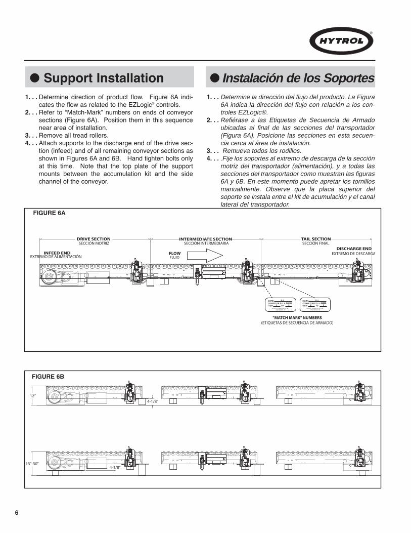
Determine direction of product flow. Figure 6A indi-cates the flow as related to the EZLogic® controls.Refer to “Match-Mark” numbers on ends of conveyorsections (Figure 6A). Position them in this sequencenear area of installation.Remove all tread rollers.Attach supports to the discharge end of the drive sec-tion (infeed) and of all remaining conveyor sections asshown in Figures 6A and 6B. Hand tighten bolts onlyat this time. Note that the top plate of the supportmounts between the accumulation kit and the sidechannel of the conveyor.
Determine la dirección del flujo del producto. La Figura6A indica la dirección del flujo con relación a los con-troles EZLogic®.Refiérase a las Etiquetas de Secuencia de Armadoubicadas al final de las secciones del transportador(Figura 6A). Posicione las secciones en esta secuen-cia cerca al área de instalación.Remueva todos los rodillos.
.Fije los soportes al extremo de descarga de la secciónmotriz del transportador (alimentación), y a todas lassecciones del transportador como muestran las figuras6A y 6B. En este momento puede apretar los tornillosmanualmente. Observe que la placa superior delsoporte se instala entre el kit de acumulación y el canallateral del transportador.
l Support Installation1. . .
2. . .
3. . .4. . .
1. . .
2. . .
3. . .4. . .
l Instalación de los Soportes
FIGURE 6A
"MATCH MARK" NUMBERS(ETIQUETAS DE SECUENCIA DE ARMADO)
SECCIÓN INTERMEDIARIA SECCIÓN FINAL
EXTREMO DE DESCARGA
SECCIÓN MOTRIZ
EXTREMO DE ALIMENTACIÓN FLUJOFLOWINFEED END
DRIVE SECTION
DISCHARGE END
INTERMEDIATE SECTION TAIL SECTION
MARKCONVEYOR F.O. #ITEM TO
HYTROL CONVEYOR CO. INC.JONESBORO, AR
P-1
1 234268
MARKCONVEYOR F.O. #ITEM TO
HYTROL CONVEYOR CO. INC.JONESBORO, AR
P-1
2 134268
FIGURE 6B
12”
4-1/8”
13"-30"4-1/8”

7
l Conveyor Set-Up l Montaje del Transportador
Mark a chalk line on floor to locate center of the con-veyor.During installation, check to make sure each sectionis square. Measure the diagonals from corner to cor-ner of the frame. If they are not equal, the framemust be squared. Attach a come-along or someother suitable pulling device across longest cornersand pull until the section is square.Place the drive section (infeed) in position.Install remaining sections, placing end without sup-port on extended support of previous section.Fasten sections together with butt couplings andsupport mounting plates. Attach channel brace tocross member of floor support (Figure 8A). Handtighten bolts only.Check to see that conveyor is level across width andlength of unit. Shim supports as necessary.After all sections have been squared and levelled,tighten all butt couplings, support mounting andchannel brace bolts, and lag supports to floor.Connect air lines and EZLogic® cables at sectionjoints as shown in “Figure 8B”.Connect 110 VAC power to IOP and connect 24 VDCpower from the IOP to the conveyor (Figure 8C).NOTE: See the EZLogic® GEN3 Component Manualfor more information on IOP connections.Connect main air supply line to FR (Filter/ Regula-tor). (Figure 8C).Set regulator to working pressure of 40 P.S.I. NOTE:See Packing List for maintenance instructions onHow To Adjust & Lubricate the FR.Install electrical controls and wire motor. See Page 9.Install and track belt per instructions on Pages 12,13, and 14. Install tread rollers.
-1. . .
2. . .
3. . .4. . .
5. . .
6. . .
7. . .
8. . .
9. . .
10. . .
11. . .
12. . .13. . .
14. . .
Marque con tiza una línea en el suelo para ubicar elcentro del transportador.Durante la instalación, certifique que cada seccióndel transportador esté escuadrada. Determine lasdiagonales de la estructura midiendo la distanciaentre las esquinas de los canales. Si las dimen-siones no son iguales, la sección necesitará serescuadrada. Fije cualquier dispositivo tirante a laesquina más larga y hale hasta que la sección estéescuadrada.Coloque la sección motriz (alimentación) en posición.Instale las secciones restantes colocando el extremosin soporte en la placa pivote del soporte de la sección anterior.Asegure las secciones con placas de empalme y pla-cas pivote. Fije la abrazadera del canal a la traviesadel soporte a piso (Figura 8A). Apriete los tornillosmanualmente.Revise que el transportador este nivelado a lo anchoy largo de la unidad. Ajuste los soportes como seanecesario.Despúes de que las secciones esten escuadradas yniveladas, apriete todos los tornillos de las placas deempalme, placas pivote y de la abrazadera delcanal, y áncle el transportador al piso.Conecte las líneas de aire y los cables del contro-lador de zona EZLogic en las secciones de unióncomo muestra la figura 8B.Conecte la corriente alterna de 110V al IOP yconecte la corriente directa de 24V del IOP al trans-portador (Figura 8C). NOTA: Vea el Manual deComponentes EZLogic® GEN3 para mayor informa-ción sobre las conexiones del IOP.Conecte la línea principal de aire al Filtro/Regulador(F/R) (Figura 8C).Establezca el Regulador a una presión de 40 P.S.I.
NOTA: Refiérase a la Lista de Empaque parainstrucciones de mantenimiento en cómo ajustar ylubricar el Filtro/Regulador.Instale los controles eléctricos y conecte el motor.Vea la página 9.Instale y alinee la banda de acuerdo a las instruc-ciones de las páginas 12, 13 y 14.Instale los rodillos.
1. . .
2. . .
3. . .
4. . .
5. . .
6. . .
7. . .
8. . .
9. . .
10. . .
11. . .
12. . .
13. . .
14. . .

8
CHANNEL BRACE
BUTT COUPLING
FLOOR SUPPORTEZLOGIC® ACCUMULATION KIT
SPACERESPACIADOR
PLACA DE EMPALME
ABRAZADERA DEL CANAL
SOPORTE A PISO(MÓDULO DE ACUMULACIÓN EZLOGIC®)
FIGURE 8A
l Conveyor Set-Up l Montaje
FIGURE 8B
LINEA DE AIRE
FILTER/REGULATOR
IOP (MUST BE MOUNTED TO ORIENT LABEL RIGHT SIDE UP)
AIR LINE
IOP T CABLE
DC
AC
IOP (DEBE SER INSTALADO DE TAL FORMA QUE LA ETIQUETA ESTÉ EN LA POSICIÓN CORRECTA)FILTRO/REGULADOR
CABLE T DEL IOP
FIGURE 8C
9
WARNING!Electrical controls shall be installed and wired by aqualified electrician. Wiring information for the motorand controls are furnished by the equipment manufac-turer.
CONTROLS
Electrical Code: All motor controls and wiring shall conformto the National Electrical Code (Article 670 or other applica-ble articles) as published by the National Fire ProtectionAssociation and as approved by the American StandardsInstitute, Inc.
CONTROL STATIONS
A) Control stations should be so arranged and located thatthe operation of the equipment is visible from them, andshall be clearly marked or labeled to indicate the functioncontrolled.
B) A conveyor which would cause injury when started shallnot be started until employees in the area are alerted by asignal or by a designated person that the conveyor is aboutto start.
When a conveyor would cause injury when started andis automatically controlled or must be controlled from aremote location, an audible device shall be provided whichcan be clearly heard at all points along the conveyor wherepersonnel may be present. The warning device shall beactuated by the controller device starting the conveyor andshall continue for a required period of time before the con-veyor starts. A flashing light or similar visual warning may beused in conjunction with or in place of the audible device ifmore effective in particular circumstances.
Where system function would be seriously hindered oradversely affected by the required time delay or where theintent of the warning may be misinterpreted (i.e., a workarea with many different conveyors and allied devices),clear, concise, and legible warning shall be provided. Thewarning shall indicate that conveyors and allied equipmentmay be started at any time, that danger exists, and that per-sonnel must keep clear. The warnings shall be providedalong the conveyor at areas not guarded by position or loca-tion.
C) Remotely and automatically controlled conveyors, andconveyors where operator stations are not manned or arebeyond voice and visual contact from drive areas, loadingareas, transfer points, and other potentially hazardous loca-tions on the conveyor path not guarded by location, position,or guards, shall be furnished with emergency stop buttons,pull cords, limit switches, or similar emergency stopdevices.
¡ADVERTENCIA!Los controles eléctricos deben ser conectados e insta-lados por un electricista calificado. La información sobreel cableado del motor y los controles será proporcionadapor el fabricante del equipo.
CONTROLES
Código Eléctrico: Todos los controles del motor y lasconexiones deben ajustarse al “National Electrical Code”(Artículo 670 u otros artículos aplicables) como fué publicadopor la “National Fire Protection Association” y aprobado por el “American Standards Institute, Inc”.
ESTACIONES DE CONTROL
A) Las estaciones de control deberán estar arregladas y ubi-cadas en lugares donde el funcionamiento del equipo sea vi-sible y deberán estar claramente marcadas o señaladas paraindicar la función controlada.
B) Un transportador que pueda causar lesiones cuando espuesto en marcha, no deberá ponerse en funcionamientohasta que los trabajadores en el área sean alertados por unaseñal o por una persona designada que indique que el trans-portador está a punto de arrancar.Cuando un transportador pueda causar lesiones al arrancar yes controlado automáticamente o controlado desde una ubi-cación lejana, se deberá proporcionar un dispositivo sonoro elcual pueda ser escuchado claramente en todos los puntos a lolargo del transportador donde el personal pueda estar pre-sente. El dispositivo de advertencia deberá ser activado por eldispositivo de arranque del transportador y deberá continuarsonando por un determinado periodo de tiempo antes de queel transportador empiece a funcionar. Una luz intermitente ouna advertencia visual similar puede ser utilizada con o enlugar del dispositivo sonoro si es más efectivo en circunstan-cias particulares.Cuando el funcionamiento del sistema pueda ser seriamenteobstruído o adversamente afectado por el tiempo de retardorequerido, o cuando el intento de advertencia pueda ser malinterpretado (ej., un área de trabajo con diversas líneas detransportadores y los dispositivos de advertencia relaciona-dos), advertencias claras, concisas y legibles deben ser pro-porcionadas. Las advertencias deberán indicar que los trans-portadores y los equipos relacionados pueden ser puestos enmarcha en cualquier momento, que existe un peligro y que elpersonal debe mantenerse alejado. Estas advertencias debenser proporcionadas a lo largo del transportador en áreas queno sean protegidas por la posición o la ubicación.
C) Los transportadores controlados automáticamente o desdeestaciones lejanas, y los transportadores donde las estacionesde funcionamiento no estén controladas por una persona, o
l Electrical Equipment l Equipo Eléctrico

10
All such emergency stop devices shall be easily identifi-able in the immediate vicinity of such locations unlessguarded by location, position, or guards. Where the design,function, and operation of such conveyor clearly is not haz-ardous to personnel, an emergency stop device is notrequired.
The emergency stop device shall act directly on the con-trol of the conveyor concerned and shall not depend on thestopping of any other equipment. The emergency stopdevices shall be installed so that they cannot be overriddenfrom other locations.
D) Inactive and unused actuators, controllers, and wiringshould be removed from control stations and panel boards,together with obsolete diagrams, indicators, control labels,and other material which serve to confuse the operator.
SAFETY DEVICES
A) All safety devices, including wiring of electrical safetydevices, shall be arranged to operate in a “Fail-Safe” man-ner, that is, if power failure or failure of the device itselfwould occur, a hazardous condition must not result.
B) Emergency Stops and Restarts. Conveyor controls shallbe so arranged that, in case of emergency stop, manualreset or start at the location where the emergency stop wasinitiated, shall be required of the conveyor(s) and associat-ed equipment to resume operation.
C) Before restarting a conveyor which has been stoppedbecause of an emergency, an inspection of the conveyorshall be made and the cause of the stoppage determined.The starting device shall be locked out before any attemptis made to remove the cause of stoppage, unless operationis necessary to determine the cause or to safely remove thestoppage.
Refer to ANSI Z244.1-1982, American National Standard forPersonnel Protection – Lockout/Tagout of Energy Sources– Minimum Safety Requirements and OSHA StandardNumber 29 CFR 1910.147 “The Control of Hazardous Ener-gy (Lockout/Tagout).”
estén mas allá del alcance de la voz y del contacto visual delas áreas de conducción, áreas de carga, puntos de transfe-rencia y otros sitios potencialmente peligrosos localizadosen la trayectoria del transportador que no tenga protecciónpor posición, ubicación o guardas, deberán ser equipadoscon interruptores, cordones o interruptores de límite o dis-positivos similares para paradas de emergencia.Todos estos dispositivos de parada de emergencia deberánser fácilmente identificables en las cercanías inmediatas alos puntos potencialmente peligrosos, a no ser que esténprotegidos por su ubicación, posición o protegidos conguardas. Donde el diseño, el funcionamiento, y la operaciónde tales transportadores no represente un claro peligro parael personal, un dispositivo de parada de emergencia no esnecesario. El dispositivo de parada de emergencia deberá actuar direc-tamente en el control del transportador concerniente y nodeberá depender de la parada de cualquier otro equipo. Losdispositivos de parada de emergencia deberán ser instala-dos de tal forma que no puedan ser anulados desde otraslocalidades.
D) Los dispositivos, controles desactivados o en desuso ylas conexiones, deberán ser removidos de las estaciones decontrol y de los tableros de mando, junto con los diagramas,indicadores, etiquetas de control y otros materiales obsole-tos, los cuales se prestan para confundir al operador.
DISPOSITIVOS DE SEGURIDAD
A) Todos los dispositivos de seguridad, incluyendo la co-nexión de dispositivos eléctricos, deben estar dispuestospara operar en una manera de “autoprotección”; es decir, sise presenta una pérdida de corriente o un fallo en el mismodispositivo, esto no debe resultar en una situación peligrosa.
B) Paradas de Emergencia y Reactivadores. Los controlesdel transportador deberán estar dispuestos de tal maneraque, en caso de una parada de emergencia, se requiere unactivador o un arrancador manual en el lugar donde la para-da de emergencia se presente para reanudar la operacióndel transportador o transportadores y el equipo asociado.
C) Antes de reiniciar un transportador que ha sido detenidopor una emergencia, debe realizarse una revisión del trans-portador y determinarse la causa de la parada. El dispositivode arranque deberá ser bloqueado antes de intentar corregirel problema, a no ser que la operación del transportador seanecesaria para determinar la causa de la parada o para solu-cionar el problema.Refiérase al ANSI Z244.1-1982, American National Standardfor Personnel Protection - Lockout/Tagout of Energy Sources- Minimum Safety Requirements and OSHA StandardNumber 29 CFR 1910.147 “The Control of HazardousEnergy (Lockout/Tagout).”
11
OPERATION
A) Only trained employees shall be permitted to operate conveyors.Training shall include instruction in operation under normal condi-tions and emergency situations.
B) Where employee safety is dependent upon stopping and/orstarting devices, they shall be kept free of obstructions to permitready access.
C) The area around loading and unloading points shall be keptclear of obstructions which could endanger personnel.
D) No person shall ride the load-carrying element of a conveyorunder any circumstances unless that person is specifically autho-rized by the owner or employer to do so. Under those circum-stances, such employee shall only ride a conveyor which incorpo-rates within its supporting structure, platforms or control stationsspecifically designed for carrying personnel. Under no circum-stances shall any person ride on any element of conveyor. Ownersof conveyors should affix warning devices to the conveyor readingDo Not Ride Conveyor.
E) Personnel working on or near a conveyor shall be instructed asto the location and operation of pertinent stopping devices.
F) A conveyor shall be used to transport only material it is capableof handling safely.
G) Under no circumstances shall the safety characteristics of theconveyor be altered if such alterations would endanger personnel.
H) Routine inspections and preventive and corrective maintenanceprograms shall be conducted to insure that all safety features anddevices are retained and function properly.
I) Personnel should be alerted to the potential hazard of entangle-ment in conveyors caused by items such as long hair, loose cloth-ing, and jewelry.
J) As a general rule, conveyors should not be cleaned while in oper-ation. Where proper cleaning requires the conveyor to be in motionand a hazard exists, personnel should be made aware of the asso-ciated hazard.
OPERACION
l Conveyor Start-UpBefore conveyor is turned on, check for foreign objects that mayhave been left inside conveyor during installation. These objectscould cause serious damage during start-up.After conveyor has been turned on and is operating, check motors,reducers, and moving parts to make sure they are working freely.
CAUTION!Because of the many moving parts on the conveyor, allpersonnel in the area of the conveyor need to bewarned that the conveyor is about to be started.
l Operation Safety Precautions l Medidas de Seguridad en la Operación
A) Solo se deberá permitir operar los transportadores a empleadosentrenados. El entrenamiento debe incluir instrucciones de operaciónbajo condiciones normales y en situaciones de emergencia.
B) Cuando la seguridad de los trabajadores depende de dispositivosde parada y/o arranque, tales dispositivos deben mantenerse libres deobstrucciones para permitir un acceso rápido.
C) El área alrededor de los puntos de carga y descarga deberá man-tenerse libre de obstrucciones, las cuales podrían poner en peligro alpersonal.
D) Ninguna persona deberá montarse en la parte de conducción decarga de un transportador bajo ninguna circunstancia al menos queesta persona esté autorizada por el dueño o por el supervisor. Bajoestas circunstancias, el empleado deberá montarse solamente en untransportador que tenga incorporado en su estructura, plataformas oestaciones de control especialmente diseñadas para el traslado de per-sonal. Bajo ninguna circunstancia, persona alguna deberá subirse acualquier elemento de un transportador. Los dueños de los trans-portadores deben añadir señales de advertencia al transportador conel texto: "No Montarse en Transportador".
E) El personal que esté trabajando en o cerca al transportador, deberáser instruído en cuanto a la ubicación y operación de los dispositivospertinentes de parada.
F) Un transportador deberá ser utilizado para transportar solamente losproductos que sea capaz de manejar en forma segura.
G) Bajo ninguna circunstancia deberán ser alteradas las característi-cas de seguridad de un transportador si tales alteraciones pudieranponer en peligro al personal.
H) Inspecciones rutinarias deberán llevarse a cabo al igual que pro-gramas de mantenimiento preventivo y correctivo, con el fín de asegu-rar que todos los dispositivos y medidas de seguridad se conserven enbuen estado y funcionen correctamente.
I) El personal deberá ser advertido de causas de peligros potencialestales como enredos en transportadores por llevar cabello largo, ropasuelta o joyas.
J) Como regla general, los transportadores no deberán limpiarse mien-tras estén en funcionamiento. Cuando se requiera limpiar el trans-portador estando en movimiento y exista posibilidad de peligro, el per-sonal deberá ser advertido de este peligro asociado.
lArranque del Transportador
¡PRECAUCION!Debido a la cantidad de partes en movimiento en eltransportador, todo el personal en el área del trans-portador necesita ser advertido de que este está apunto de ponerse en marcha.
Antes de poner en marcha el transportador, revise si hay objetosajenos que puedan haber sido dejados dentro del transportadordurante la instalación. Estos objetos pueden causar serios daños en elarranque. Después de poner en marcha el transportador, cuando esté operando,revise los motores, reductores y partes en movimiento para estarseguro de que están trabajando libremente.

12
DRIVE PULLEY POLEA MOTRIZ
RODILLO DE ALINEACIÓN
ENLACE DE BANDA
RODILLO DE ALINEACIÓN
RODILLOS POLEA DE RETORNO
BANDA
BANDA
PASADOR DE ENLACE
RODILLO DE RETORNO
TREAD ROLLERS
BELT
TAIL PULLEY(TAKE-UP)
SNUB IDLERRETURN IDLERSNUB IDLER
DRIVE BELT
LACING PIN
BELT LACINGFIGURE 12B
DRIVE PULLEY POLEA MOTRIZ
RODILLO DE ALINEACIÓN
ENLACE DE BANDA
RODILLO DE ALINEACIÓN
RODILLOS POLEA DE RETORNO
BANDA
BANDA
PASADOR DE ENLACE
RODILLO DE RETORNO
TREAD ROLLERS
BELT
TAIL PULLEY(TAKE-UP)
SNUB IDLERRETURN IDLERSNUB IDLER
DRIVE BELT
LACING PIN
BELT LACING
FIGURE 12A
• Belt Installation • Instalación de la BandaINSTALLING THE BELTThe conveyor belt has been cut to the proper length and lac-ing installed at the factory. To install follow these steps:
Thread belt through conveyor as shown in Figure12A.Pull ends together and insert lacing pin (Figure 12B). Adjust belt tension with take-up pulley. Keep pulleysquare by moving both take-up bolts an equalamount. Maintain enough tension so drive pulley willnot slip when carrying the rated load.Track belt per instructions on Pages 13 and 14.
INSTALANDO LA BANDALa banda del transportador ha sido previamente cortada yenlazada en la fábrica. Para instalarla siga los siguientespasos:1. . .
2. . .3. . .
4. . .
Coloque la banda a través del transportador (Fig. 12A). Junte los extremos e inserte el pasador de enlace (Fig.12B). Ajuste la tensión de la banda con las poleas tensoras ocon la polea de retorno. Mantenga la polea escuadradamoviendo los tornillos tensores a la misma distancia.Mantenga suficiente tensión para que la polea motriz nose resbale al transportar la carga estimada.Alinee la banda de acuerdo a las instrucciones de lapáginas 13 y 14.
1. . .2. . .
3. . .
4. . .
NOTE: If belt ends cannot be pulled together by hand, itmay be necessary to loosen take-ups (at tail pulley, etc.)to minimum position or use a belt puller so lacing pincan be easily inserted.
NOTA: Si los extremos de la banda no pueden serunidos manualmente, afloje los tornillos tensores (en lapolea de retorno, etc.) al mínimo ó utilice un jalador debanda hasta que el pasador pueda ser fácilmente inser-tado.XXXX
CAUTION!Excessive slippage will reduce belt life and damagedrive pulley lagging. Never apply more tension than isneeded.Over-tension will cause extra wear to belt and bearingsand will require extra power from drive.
¡PRECAUCION!Si la banda patina excesivamente su vida útil seráreducida considerablemente y se dañará el reves-timiento de la polea motriz. Nunca aplique más tensiónde la necesaria. Una sobretensión causará mayordesgaste de la banda y los rodamientos y hará que sereguirerá mayor potencia de la unidad motriz.

13
IMPORTANT: The conveyor belt should be checkedfor proper tracking prior to installing tread rollers. Thiswill allow easy access to items that may need adjusting.The following inspection should be made before physi-cally attempting to track the belt.
DRIVE PULLEY
TAIL PULLEY
TAKE-UP BOLT
SNUB IDLER
SNUB IDLERIDLER BRACKET
IDLER BRACKETSOPORTE DEL RODILLO
SOPORTE DEL RODILLO
POLEA DE RETORNO
TORNILLO TENSOR
TORNILLOS DE MONTAJE
TORNILLOS DE MONTAJE
RODILLO DE ALINEACIÓN
RODILLO DE ALINEACIÓN
POLEA MOTRIZ
MOUNTINGBOLTS
MOUNTINGBOLTS
“A”
“A”
FIGURE 13A
DRIVE PULLEY
TAIL PULLEY
TAKE-UP BOLT
SNUB IDLER
SNUB IDLERIDLER BRACKET
IDLER BRACKETSOPORTE DEL RODILLO
SOPORTE DEL RODILLO
POLEA DE RETORNO
TORNILLO TENSOR
TORNILLOS DE MONTAJE
TORNILLOS DE MONTAJE
RODILLO DE ALINEACIÓN
RODILLO DE ALINEACIÓN
POLEA MOTRIZ
MOUNTINGBOLTS
MOUNTINGBOLTS
“A”
“A”
FIGURE 13B
• Belt Tracking • Alineación de la Banda
PRE-TRACKING INSPECTIONBefore attempting to physically track the belt:
Make sure all bed sections are square. Make sure conveyor is level across the width andlength of unit. Adjust supports as necessary.Make sure all pulleys, return idlers, and snub idlersare square with conveyor bed. (Figures 13A thru 13-B). Dimension “A” should be equal on both sides ofunit.Make sure belt has been properly threaded throughconveyor. See “Belt Installation”, Page 12.
INSPECCION PREVIA A LA ALINEACION DE LA BANDAAntes de proceder a alinear la banda:
1. . .2. . .
3. . .
4. . .
Asegúrese de que las camas están escuadradas. Asegúrese de que el transportador está nivelado alo ancho y largo de la unidad. Ajuste los soportes sies necesario.Asegúrese de que todas las poleas, los Rodillosde Alineación y de Retorno están escuadrados conla cama del transportador (Fig. 13A a la 13B). LaDimensión “A” debe ser igual en ambos lados de launidad.Aseguresé de que la banda haya sido colocadaadecuadamente en el transportador. Vea“Instalación de la Banda”, Pág. 12.
1. . .2. . .
3. . .
4. . .
IMPORTANTE: Antes de instalar los rodillos se deberevisar que la banda esté alineada. Esto facilitará elacceso a partes que puedan requerir ajuste. La siguienteinspección debe ser hecha antes de tratar de alinear labanda.
14
CAUTION!Only trained personnel should track conveyor beltwhich must be done while conveyor is in operation.
DRIVE PULLEY
TAIL PULLEY
BELT DIRECTION
SIDE “X”
SIDE “Y”
BELTSNUB IDLER
TAIL
EN
D
DR
IVE
EN
D
FIGURE 14ADRIVE PULLEYPOLEA MOTRIZ
SNUB IDLERRODILLO DE ALINEACIÓN
TAIL PULLEYPOLEA DE RETORNO
BELTBANDA
SIDE “Y”LADO Y
SIDE “X”LADO X
BELT DIRECTIONDIRECCIÓN DE LA BANDA
DRIV
E EN
DEX
TREM
O M
OTRI
Z
TAIL
END
EXTR
EMO
MOT
RIZ
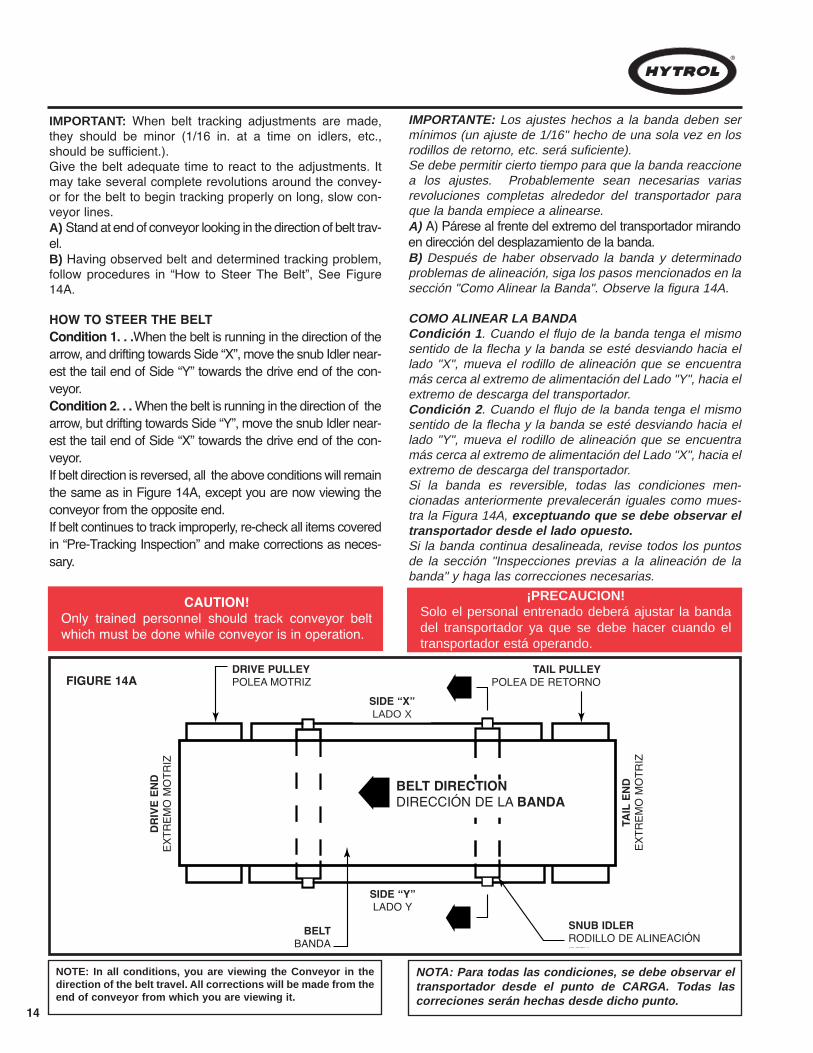
IMPORTANT: When belt tracking adjustments are made,they should be minor (1/16 in. at a time on idlers, etc.,should be sufficient.).Give the belt adequate time to react to the adjustments. Itmay take several complete revolutions around the convey-or for the belt to begin tracking properly on long, slow con-veyor lines.A) Stand at end of conveyor looking in the direction of belt trav-el.B) Having observed belt and determined tracking problem,follow procedures in “How to Steer The Belt”, See Figure14A.
HOW TO STEER THE BELTCondition 1. . .When the belt is running in the direction of thearrow, and drifting towards Side “X”, move the snub Idler near-est the tail end of Side “Y” towards the drive end of the con-veyor.Condition 2. . . When the belt is running in the direction of thearrow, but drifting towards Side “Y”, move the snub Idler near-est the tail end of Side “X” towards the drive end of the con-veyor.If belt direction is reversed, all the above conditions will remainthe same as in Figure 14A, except you are now viewing theconveyor from the opposite end.If belt continues to track improperly, re-check all items coveredin “Pre-Tracking Inspection” and make corrections as neces-sary.
IMPORTANTE: Los ajustes hechos a la banda deben sermínimos (un ajuste de 1/16" hecho de una sola vez en losrodillos de retorno, etc. será suficiente).Se debe permitir cierto tiempo para que la banda reaccionea los ajustes. Probablemente sean necesarias variasrevoluciones completas alrededor del transportador paraque la banda empiece a alinearse.A) A) Párese al frente del extremo del transportador mirandoen dirección del desplazamiento de la banda.B) Después de haber observado la banda y determinadoproblemas de alineación, siga los pasos mencionados en lasección "Como Alinear la Banda". Observe la figura 14A.
COMO ALINEAR LA BANDACondición 1. Cuando el flujo de la banda tenga el mismosentido de la flecha y la banda se esté desviando hacia ellado "X", mueva el rodillo de alineación que se encuentramás cerca al extremo de alimentación del Lado "Y", hacia elextremo de descarga del transportador.Condición 2. Cuando el flujo de la banda tenga el mismosentido de la flecha y la banda se esté desviando hacia ellado "Y", mueva el rodillo de alineación que se encuentramás cerca al extremo de alimentación del Lado "X", hacia elextremo de descarga del transportador.Si la banda es reversible, todas las condiciones men-cionadas anteriormente prevalecerán iguales como mues-tra la Figura 14A, exceptuando que se debe observar eltransportador desde el lado opuesto.Si la banda continua desalineada, revise todos los puntosde la sección "Inspecciones previas a la alineación de labanda" y haga las correcciones necesarias.
NOTE: In all conditions, you are viewing the Conveyor in thedirection of the belt travel. All corrections will be made from theend of conveyor from which you are viewing it.
NOTA: Para todas las condiciones, se debe observar eltransportador desde el punto de CARGA. Todas lascorreciones serán hechas desde dicho punto.
¡PRECAUCION!Solo el personal entrenado deberá ajustar la bandadel transportador ya que se debe hacer cuando eltransportador está operando.
15
CARTON#3
CARTON#2
CARTON#1
ZONE #3 ZONE #2 ZONE #1
ZONECONTROLLER
"C"
ZONECONTROLLER
"B"
ZONECONTROLLER
"A"
CARTON#3
CARTON#2
CARTON#1
CARTON#3
CARTON#2
CARTON#1
ZONECONTROLLER
"C"
ZONECONTROLLER
"B"
ZONECONTROLLER
"A"
GAP GAP
GAP
ZONECONTROLLER
"C"
ZONECONTROLLER
"B"
ZONECONTROLLER
"A"
FIGURE 15BFIGURE 15A
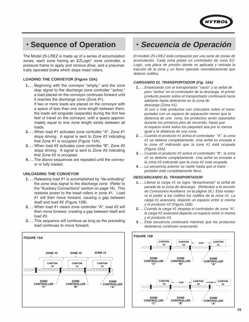
• Sequence of Operation • Secuencia de OperaciónThe Model 25-LREZ is made up of a series of accumulationzones, each zone having an EZLogic® zone controller, apressure frame to apply and remove drive, and a pneumat-ically operated brake which stops tread rollers.
LOADING THE CONVEYOR (Figure 15A)
Beginning with the conveyor "empty," and the zonestop signal to the discharge zone controller "active,"a load placed on the conveyor continues forward untilit reaches the discharge zone (Zone #1).If two or more loads are placed on the conveyor witha space of less than one zone length between them,the loads will singulate (separate) during the first fewfeet of travel on the conveyor, until a space approxi-mately equal to one zone length exists between allloads.When load #1 activates zone controller "A", Zone #1stops driving. A signal is sent to Zone #2 indicatingthat Zone #1 is occupied (Figure 15A).When load #2 activates zone controller "B", Zone #2stops driving. A signal is sent to Zone #3 indicatingthat Zone #2 is occupied.The above sequences are repeated until the convey-or is fully loaded.
El modelo 25-LREZ está compuesto por una serie de zonas deacumulación. Cada zona posee un controlador de zona EZ-Logic, una placa de presión donde es aplicada y retirada latracción de la zona y un freno operado neumáticamente quedetiene rodillos.
CARGANDO EL TRANSPORTADOR (Fig. 15A)1. . .
2. . .
3. . .
4. . .
Empezando con el transportador "vacio" y la señal deparo "activa" en el controlador de la descarga, el primerproducto puesto sobre el transportador continuará haciaadelante hasta detenerse en la zona dedescarga (Zona #1).Si uno o más productos son colocados sobre el trans-portador con un espacio de separación menor que ladistancia de una zona, los productos serán separadosdurante los primeros pies de recorrido, hasta queel espacio entre todos los paquetes sea por lo menosigual a la distancia de una zona.Cuando el producto #1 activa el controlador "A", la zona#1 se detiene completamente. Una señal es enviada ala zona #2 indicando que la zona #1 está ocupada(Figura 15A).Cuando el producto #2 activa el controlador "B", la zona#2 se detiene completamente. Una señal es enviada ala zona #3 indicando que la zona #2 está ocupada.La secuencia anterior se repite hasta que el trans -portador esté completamente lleno.
1. . .
2. . .
3. . .
4. . .
Releasing load #1 is accomplished by "de-activating"the zone stop signal to the discharge zone (Refer tothe "Auxiliary Connections" section on page 16). Thisrestores power to the tread rollers in zone #1. Load#1 will then move forward, causing a gap betweenitself and load #2 (Figure 15B).When load #1 clears zone controller "A", load #2 willthen move forward, creating a gap between itself andload #3.This sequence will continue as long as the precedingload continues to move forward.
1. . .
2. . .
3. . .
Liberar la carga #1 se logra "desactivando" la señal deparada de la zona de descarga. (Refieráse a la secciónde Conexiones Auxiliares en la página 16.) Esto restau-ra el poder a los rodillos los rodillos de la zona #1. Lacarga #1 avanzará, dejando un espacio entre si mismay el producto #2 (Figura 15B).Cuando la carga #1 despeja el controlador de zona "A",la carga #2 avanzará dejando un espacio entre si mismay el producto #3.Esta secuencia continuará mientras que los productosdelanteros continuen avanzando.
1. . .
2. . .
3. . .
UNLOADING THE CONVEYORDESCARGANDO EL TRANSPORTADOR
RON, I took this wording from the ABEZ. While the words are not EXACTLYthe same, they are pretty close. I am trying to duplicate as much as I can fromapproved IM’s so that there will be much less Spanish Translation to do. If Iam off-base on this, please let me know. Thank you.

16
• EZLogic® System • Sistema EZLogic®
EZLogic® Accumulation System ConnectionsThe Model 25-LREZ is equipped with the EZLogic® accu-mulation system. The following basic information may beused as a guide during the installation and initial setup ofthe conveyor. For detailed information about EZLogic® sys-tem components, options, functions, and programming,please refer to the EZLogic® GEN3 Component Manual.Each EZLogic® zone controller is equipped with sealed con-nectors for zone-to-zone communication, solenoid output,and zone stop connections (Figure 17B). These connec-tions are described in the following sections.
ZONE CONNECTIONSEach zone controller has a cordset terminated with a femalemicro-connector and a male micro-connector. This cordsetprovides power to all the zone controllers on the conveyoras well as communication between zone controllers (Figure.17A and 17B).All zone controllers are mounted and connected at the fac-tory within each conveyor section. Connections betweensections are made at installation. (See Conveyor Set-Up,pages 7 and 8). The cordset from one zone controller isalways connected to the cordset on the upstream side of it.This is the way the zone controllers know which directionproduct is flowing.The cordset on the infeed end of the conveyor is simplybundled and tied in the accumulation channel and is notconnected. The infeed cordset may be replaced with aninfeed zone terminator (P/N 032.550). Protective caps areprovided to seal unused connectors.An optional conveyor-to-conveyor connector is requiredwhen two conveyors are joined end-to-end. Please refer tothe EZLogic® GEN3 Component Manual for more informa-tion.
SOLENOID CONNECTIONSEach zone controller has a built-in cable to provide a zonedrive/no drive output to the solenoid air valve operating thezone. This cable is terminated with a female Pico-stylesealed snap-lock connector. Connection is made by push-ing the cable connector onto the corresponding male con-nector of the valve until it snaps in.Please note that this output is only to be used to operate thezone mechanism of the conveyor. It is not to be used as anoutput signal to other control devices. If a control output isneeded, an optional auxiliary module with I/O should beused. Please refer to the EZLogic® GEN3 Component Man-ual for more information.
AUXILIARY CONNECTIONSEvery EZLogic® zone controller is equipped with an auxiliaryport to accept a zone stop signal, a slug input signal, or azone wake-up signal by simply connecting an auxiliary inputcable to the auxiliary port of the controller and then wiringthe two wires of the cable to any “dry contact” type switch-
Conexiones del Sistema de Acumulación EZLogic®
El Modelo 25-LREZ está equipado con un sistema de acumu-lación EZLogic®. La siguiente información puede ser usadacomo guía durante la instalación y el montaje del transportador.Para información más detallada sobre los componentes delsistema EZLogic®, sus opciones, funciones, y programación,refiérase al Manual de Componentes del EZLogic Gen 3. Cadacontrolador de zona EZLogic® está equipado con un conectorsellado de comunicación zona-a-zona, salida solenoide yconexiones de parada (Fig. 17B). Estas conexiones sedescriben a continuación.
CONEXIONES DE ZONACada controlador de zona posee un cable que termina conmicro-conector hembra y un micro-conector macho. Por mediode este cable se transmite poder y comunicación entre los con-troladores (Fig. 17A y 17B).Todos los controladores son montados y conectados en lafábrica en cada seccion del transportador. Las conexionesentre las secciones se hacen durante la instalación (VerPáginas 7 y 8). El cable de un controlador estará siempreconectado al controladora de la zona anterior para que el con-trolador sepa la dirección del flujo de los productos.El cable del controlador en la zona de carga simplemente esamarrado al canal y no será conectado. . El cable en la zonade carga puede ser reemplazado con una terminal de ali-mentacion (N/P 032.550). Se proporcionan capas protectoraspara sellar los conectores que no se usarán.Cuando se juntan dos transportadores, un cable conectoropcional de transportador a transportador es requerido.Refiérase al Manual de Componentes del EZLogic Gen 3 paramayor informaciónCONECTORES DE LA VALVULA SOLENOIDECada controlador de zona de acumulación posee un cable queprovee una señal de tracción/no-tracción de la zona a la válvu-la solenoide de aire que la está operando.Este cable termina con un conector "Pico-Style" hembra sella-do ajustable a presión. La conexión se hace enchufando elcable conector al conector macho de la válvula. Recuerde que esta señal debe ser exclusivamente utilizadapara operar el mecanismo de la zona del transportador. Nodebe ser utilizada como señal de salida de otro dispositivo decontrol. Si una señal de control es necesaria, un móduloopcional I/O debe ser utilizado. Refiérase al Manual deComponentes del EZLogic Gen 3 para mayor información.CONEXIONES AUXILIARESCada controlador de zona EZLogic® está equipado con unpuerto auxiliar. Este conector puede ser usado para aceptar, yaseauna señal de paro de zona, una señal de entrada continua(slug), o una señal de activación de zona, simplementeconectando el cable de entrada auxiliar al puerto auxiliar delcontrolador y después conectando los dos cables a cualquierdispositivo interruptor, como de palanca o relevador (tipo “drycontact”). No se requieren más componentes. El ajuste están-dar es para señal de paro de zona. Para usar la señal de entra-da continua (slug) o la señal de activación de zona, programelos controladores de zona según lo descrito en el “Manual de

17
Componentes del EZLogic Gen 3.Nota: No aplique voltaje a estos cables o conecte más de uncontrolador de zona a cualquier contacto. Cerrando los con-tactos de parada pondrán al controlador EZLogic® en el modo“acumulador”. El siguiente cartón que active el controlador sedetendrá en la “zona de paro” hasta que vuelva a haber con-tacto. La función de paro es usada en los transportadores paracontrolar la salida del producto de la zona de descarga. Otraszonas pueden ser conectadas con función en cualquiermomento.
ing device, such as a toggle switch or relay. No other com-ponents are required. The default setting is for a zone stopsignal. To use the signal for slug input or zone wake-up,program the zone controller as detailed in the EZLogic®
GEN3 Component Manual. Note: Do not apply a voltage to these wires, or wire morethan one controller to any one contact. Closing the zonestop contacts will place the EZLogic® controller into “accu-mulate” mode. The next carton to activate the controller willbe stopped and held in the “stop zone” until the contact isopened. The zone stop feature is used on all conveyors tocontrol the release of product from the discharge zone.Other zones may be wired for this feature at any time.
TRANSDUCER (SENSOR)
MOUNTING BASE
AUXILIARY PORT
ZONE CONTROLLER
SOLENOID OUTPUT CABLE
ZONE CONTROLLER CORDSET (MALE) (CONECTOR DE CABLE)
(BASE DE MONTAJE)
(SENSOR)
(CABLE DE SALIDA SELENOIDE)
(CONTROLADOR DE ZONA)
(PUERTO AUXILIAR)
ZONE CONTROLLER CORDSET(CABLES DEL CONTROLADOR DE ZONA)
FIGURE 17B
MAIN AIR SUPPLY LINE
TO BRAKE
AIR VALVE
EZLOGIC® ZONE CONTROLLER
SOLENOID CONNECTORTO PRESSURE FRAME HACIA LA PLACA DE PRESIÓNHACIA EL FRENO
LÍNEA PRINCIPAL DE AIRE
(CONECTOR DE SELENOIDE)
(CONTROLADOR DE ZONA DEL EZLOGIC®)
(VALVULA DE AIRE)
ZONE CONTROLLER CORDSET(CABLES DE CONTROLADOR DE ZONA)
FIGURE 17A

INFEED ZONEZONA DE ALIMENTACIÓN
CONTROLADOR DE ZONA EZLOGIC®
CONTROLADOR DE ZONA EZLOGIC®
MESA GIRATÓRIA/CRR MONTADO
CARRO DE TRANSFERENCIA/CRR MONTADOTRANSFERENCIA DE CADENA
CONTROLADOR DE ZONA EZLOGIC®CONTROLADOR DE ZONA EZLOGIC®
ZONA DE ALIMENTACIÓN
ZONA DE ALIMENTACIÓNZONA DE ALIMENTACIÓN
FLUJO FLUJO
RIELES
FLUJO
FLUJOFLOW
INFEEDCONVEYOR
TRANSPORTADOR ALIMENTADOR
INFEED ZONE
FLOW
CRR
CHAIN TRANSFER
INFEED ZONE
TURNTABLE / CRR MOUNTED
FLOW
INFEED ZONE
FLOW
TRACKS
TRANSFER CART/CRR MOUNTED
EZLOGIC® ZONE CONTROLLER
EZLOGIC®
ZONE CONTROLLER
EZLOGIC®
ZONE CONTROLLEREZLOGIC®
ZONE CONTROLLER
18
1 3
2 4
• Loading Applications • Aplicaciones de Carga
END LOADING FROM ANOTHER CONVEYOR
CONTROLS REQUIRED:If the infeed zone is occupied, some method is needed to control theinfeed conveyor (if powered). A photo cell may be placed in infeedzone to signal that zone is occupied or an EZLogic® I/O auxiliary mod-ule may be connected to the zone controller in the infeed zone to pro-vide signal that infeed zone is occupied.
CONTROLES REQUERIDOS:Si la zona de alimentación está ocupada, es necesario un método paracontrolar el transportador alimentador (si es motorizado). Se puedecolocar una fotocelda en la zona de alimentación para avisar que lazona está ocupada o puede usarse un módulo auxiliar EZLogic® conI/O conectado al controlador (módulo) de la zona en la zona de ali-mentación para proporcionar una señal que indique que la zona de ali-mentación está ocupada.
END LOADING FROM TURNTABLE
CONTROLS REQUIRED:Same as Item #1.CONTROLES REQUERIDOS:Igual al #1
END LOADING FROM CHAIN TRANSFER END LOADING FROM TRANSFER CART
(ALIMENTACION DESDE OTRO TRANSPORTADOR) (ALIMENTACION DESDE UNA MESA GIRATORIA)
(ALIMENTACION DESDE UNA TRANSFERENCIA DE CADENA) (ALIMENTACION DESDE UN CARRO DE TRANSFERENCIA)
CONTROLS REQUIRED:Same as Item #1.CONTROLES REQUERIDOS:Igual al #1
CONTROLS REQUIRED:Same as Item #1.CONTROLES REQUERIDOS:Igual al #1

19
CARGANDO EL EXTREMO O EL LADO DELTRANSPORTADOR CON MONTACARGAS5
FORK TRUCK
ZONE STOP SIGNAL
FLOW
LOADING ZONE
FORK TRUCKMONTACARGAS
MONTACARGAS
ZONA DE CARGA
FLUJO
CONTROLADOR DE ZONA EZLOGIC®
CONTROLADOR DE ZONA EZLOGIC®
SEÑAL DE PARO DE ZONA
SEÑAL DE PARO DE ZONA
ZONA PRECEDENTE
ZONE STOP SIGNAL
PRECEDINGZONE
FLOW
EZLOGIC®
ZONE CONTROLLER
EZLOGIC®
ZONE CONTROLLER
CARGANDO LA SECCIÓN INTERMEDIA DELTRANSPORTADOR (DEBE SER DESIGNADA ZONA DE CARGA)
6
• Loading Applications (Continued)
• Aplicaciones de Carga(Continúa)
CONTROLS REQUIRED:When loading the end zone, it must hold the load until the fork truck is clear. A zone stop signal to the infeed zone will do this. A photo cell to detect the fork truckor a pull switch activated by the driver may be used to activate the zone stop. EZLogic® zone controller in the infeed zone may need to be relocated to detect prod-uct before setting product in zone, otherwise the lift module will not operate. This may also be accomplished without the use of a zone stop by using the EZLog-ic® loading zone feature. See EZLogic® GEN3 component manual for details. Zone controller in loading zone will need to be diffuse when loading from the side.
CONTROLES REQUERIDOS:Cuando se carga la zona del extremo, esta debe retener la carga hasta que el montacargas se retire. Una señal de paro de zona en la zona de alimentación haráesta función. Se puede utilizar una fotocelda que detecte el montacargas o un interruptor controlado por el conductor para activar la señal de paro de zona. Elcontrolador de zona EZLogic® en la zona de alimentación puede necesitar ser reubicado para detectar el producto antes de poner el producto en la zona, de locontário, el sistema de levantamieno no opeará. Esto se puede lograr sin usar un paro de zona mediante el uso de la función “Carga de Zona EZLogic®”. Ver elmanual de componentes de EZLogic® GEN3 para mayor información.
CONTROLS REQUIRED:When loading an intermediate zone, the designated loading zone and the preceding zone must be controlled. A zone stop signal to both zones will do this. Aphoto cell to detect the fork truck or a pull switch activated by the driver may be used to activate the zone stop. EZLogic® zone controller in the loading zone mayneed to be relocated to detect product before setting product in zone, otherwise the lift module will not operate. This may also be accomplished without the useof a zone stop by using the EZLogic® loading zone feature. See EZLogic® GEN3 component manual for details. Zone controller in loading zone will need to bediffuse when loading from the side.
CONTROLES REQUERIDOS:Cuando se carga sección intermedia, la zona de carga designada y la zona precedente deben ser controladas. Una señal de paro de zona en las dos zonaspuede hacer esta función. Se puede utilizar una fotocelada que detecte el montacargas o un interruptor controlado por el conductor para activar la señal de parade zona. El módulo EZLogic® en la zona de alimentación puede necesitar ser reubicado para detectar el producto antes de poner el producto en la zona, de locontario, el sistema de levantamieno no operá. Esto se puede lograr sin usar un paro de zona mediante el uso de la función “Carga de Zona EZLogic®”. Ver elmanual de componentes de EZLogic® GEN3 para mayor información.

20
DISCHARGE ZONEZONA DE DESCARGA
CONTROLADOR DE ZONA EZLOGIC®
SEÑAL DE PARO DE ZONA
TRANSPORTADOR
SEÑAL DE PARO DE ZONA
SEÑAL DE PARO DE ZONASEÑAL DE PARO DE ZONA
CARRO DE TRANSFERENCIA/CRR MONTADOTRANSFERENCIA DE CADENA
ZONA DE DESCARGA
ZONA DE DESCARGARIELES
FLUJOFLUJO
FLUJO FLUJO
ZONA DE DESCARGA
CONTROLADOR DE ZONA EZLOGIC®
CONTROLADOR DE ZONA EZLOGIC®CONTROLADOR DE ZONA EZLOGIC®
MESA GIRATÓRIA/CRR MONTADO
ZONE STOP SIGNAL
ZONE STOP SIGNAL
FLOW
TAKE-AWAYCONVEYOR
DISCHARGE ZONE
TURNTABLE/CRR MOUNTED
FLOW
FLOW
DISCHARGE ZONEDISCHARGE ZONETRACKS
TRANSFER CART/CRR MOUNTED
ZONE STOP SIGNAL
FLOW
CRR
CHAIN TRANSFER
ZONE STOP SIGNAL
EZLOGIC® ZONE CONTROLLER EZLOGIC
® ZONE
CONTROLLER
EZLOGIC® ZONE
CONTROLLEREZLOGIC®
ZONE CONTROLLER
UNLOADING ONTO ANOTHER CONVEYOR1 UNLOADING ONTO TURNTABLE3
UNLOADING ONTO CHAIN TRANSFER2 UNLOADING ONTO TRANSFER CART4
• Unloading Applications • Aplicaciones de Descarga
CONTROLS REQUIRED:A standard zone stop signal is used to hold load. Remove the signal torelease load.
CONTROLES REQUERIDOS:Una señal estándar de paro de zona se utiliza para detener la carga. Remueva laseñal para liberar la carga.
CONTROLS REQUIRED:Same as Item #1.
CONTROLES REQUERIDOS:Igual al #1
CONTROLS REQUIRED:Same as Item #1.
CONTROLES REQUERIDOS:Igual al #1
CONTROLS REQUIRED:Same as Item #1.
CONTROLES REQUERIDOS:Igual al #1
DESCARGA EN OTRO TRANSPORTADOR DESCARGA EN UNA MESA GIRATORIA
DESCARGA EN UNA TRANSFERENCIA DE CADENA DESCARGA EN UN CARRO DE TRANSFERENCIA

21
FLOW
FORK TRUCKMONTACARGAS
CONTROLADOR DE ZONA EZLOGIC®
ZONA #2
ZONA DE DESCARGA
FLUJO
SEÑAL DE PARO DE ZONA
FLUJOFLOW
FORK TRUCK
ZONE #2
UNLOADING ZONE (ZONE #1)
EZLOGIC® ZONE CONTROLLERZONA DE CONTROLADOR EZLOGIC®
MONTACARGAS
ZONE STOP SIGNAL
EZLOGIC® ZONE CONTROLLER
END UNLOADING WITH FORK TRUCK5
UNLOADING FROM INTERMEDIATE ZONE6
CONTROLS REQUIRED:The zone stop control in the end zone may be wired tostop any load entering the zone. The unloading zonefeature may be used to delay the restart of zone #2until the fork truck is clear. Zone controller in unload-ing zone will need to be diffuse when unloading fromthe side.
CONTROLS REQUIRED:A zone stop signal may be used to stop the product.The unloading zone feature may be used to delay therestart of the upstream zone until the fork truck is clear.Zone controller in unloading zone will need to be dif-fuse when unloading from the side.
DESCARGA POR EXTREMO CON MONTACARGAS
CONTROLES REQUERIDOS:El control del paro de zona en la zona extrema puedeser conectado para detener cualquier carga entrandoen la zona. La función de zona de descarga puede uti-lizarse para retardar el reinicio de la zona #2 hasta queel montacargas se retire.
DESCARGA DESDE UNA SECCION INTERMEDIA
CONTROLES REQUERIDOS:Una señal de paro de zona puede usarse para deten-er el producto. La función de zona de descarga puedeutilizarse para retardar el reinicio de la zona anteriorhasta que el montacargas se retire. El controlador dezona en la zona de descarga debe estar en “difuso”cuando se está descargando el transportador lateral-mente.
5
6
• Unloading Applications (Continued)
• Aplicaciones de Descarga(Continúa)
22
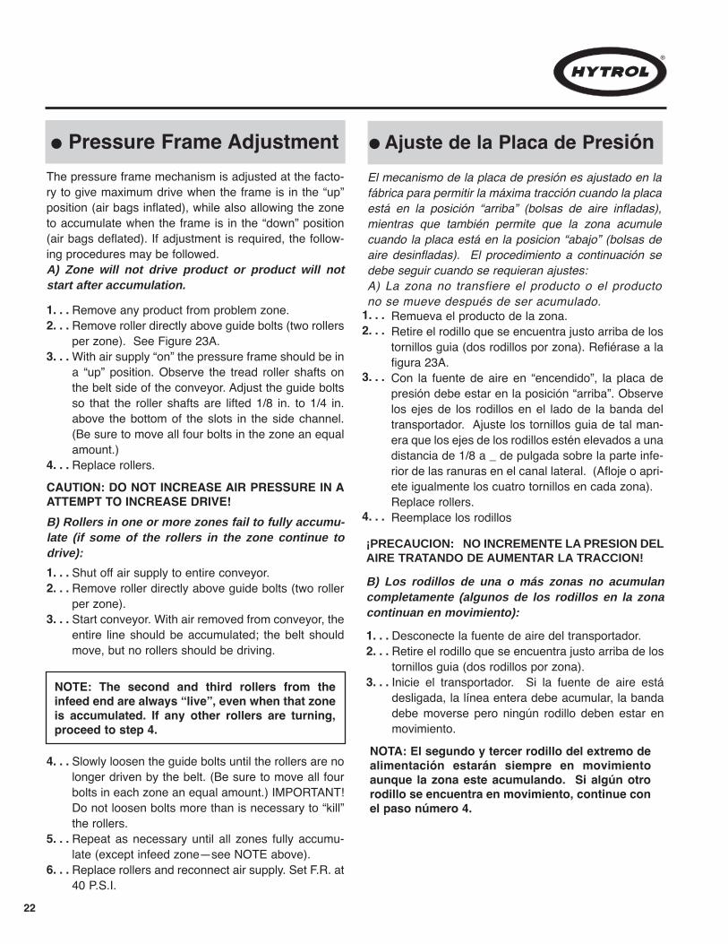
l Pressure Frame AdjustmentThe pressure frame mechanism is adjusted at the facto-ry to give maximum drive when the frame is in the “up”position (air bags inflated), while also allowing the zoneto accumulate when the frame is in the “down” position(air bags deflated). If adjustment is required, the follow-ing procedures may be followed.A) Zone will not drive product or product will notstart after accumulation.
Remove any product from problem zone.Remove roller directly above guide bolts (two rollersper zone). See Figure 23A.With air supply “on” the pressure frame should be ina “up” position. Observe the tread roller shafts onthe belt side of the conveyor. Adjust the guide boltsso that the roller shafts are lifted 1/8 in. to 1/4 in.above the bottom of the slots in the side channel.(Be sure to move all four bolts in the zone an equalamount.)Replace rollers.
1. . .2. . .
3. . .
4. . .
NOTE: The second and third rollers from theinfeed end are always “live”, even when that zoneis accumulated. If any other rollers are turning,proceed to step 4.
CAUTION: DO NOT INCREASE AIR PRESSURE IN AATTEMPT TO INCREASE DRIVE!B) Rollers in one or more zones fail to fully accumu-late (if some of the rollers in the zone continue todrive):
Shut off air supply to entire conveyor.Remove roller directly above guide bolts (two rollerper zone).Start conveyor. With air removed from conveyor, theentire line should be accumulated; the belt shouldmove, but no rollers should be driving.
1. . .2. . .
3. . .
Slowly loosen the guide bolts until the rollers are nolonger driven by the belt. (Be sure to move all fourbolts in each zone an equal amount.) IMPORTANT!Do not loosen bolts more than is necessary to “kill”the rollers.Repeat as necessary until all zones fully accumu-late (except infeed zone—see NOTE above).Replace rollers and reconnect air supply. Set F.R. at40 P.S.I.
4. . .
5. . .
6. . .
l Ajuste de la Placa de PresiónEl mecanismo de la placa de presión es ajustado en lafábrica para permitir la máxima tracción cuando la placaestá en la posición “arriba” (bolsas de aire infladas),mientras que también permite que la zona acumulecuando la placa está en la posicion “abajo” (bolsas deaire desinfladas). El procedimiento a continuación sedebe seguir cuando se requieran ajustes:A) La zona no transfiere el producto o el productono se mueve después de ser acumulado.
Remueva el producto de la zona.Retire el rodillo que se encuentra justo arriba de lostornillos guia (dos rodillos por zona). Refiérase a lafigura 23A.Con la fuente de aire en “encendido”, la placa depresión debe estar en la posición “arriba”. Observelos ejes de los rodillos en el lado de la banda deltransportador. Ajuste los tornillos guia de tal man-era que los ejes de los rodillos estén elevados a unadistancia de 1/8 a _ de pulgada sobre la parte infe-rior de las ranuras en el canal lateral. (Afloje o apri-ete igualmente los cuatro tornillos en cada zona).Replace rollers.Reemplace los rodillos
1. . .2. . .
3. . .
4. . .
¡PRECAUCION: NO INCREMENTE LA PRESION DELAIRE TRATANDO DE AUMENTAR LA TRACCION!
B) Los rodillos de una o más zonas no acumulancompletamente (algunos de los rodillos en la zonacontinuan en movimiento):
Desconecte la fuente de aire del transportador.Retire el rodillo que se encuentra justo arriba de lostornillos guia (dos rodillos por zona). Inicie el transportador. Si la fuente de aire estádesligada, la línea entera debe acumular, la bandadebe moverse pero ningún rodillo deben estar enmovimiento.
1. . .2. . .
3. . .
NOTA: El segundo y tercer rodillo del extremo dealimentación estarán siempre en movimientoaunque la zona este acumulando. Si algún otrorodillo se encuentra en movimiento, continue conel paso número 4.

23
1/8" - 1/4"
TREAD ROLLERRODILLO
RODILLO DE PRESIÓN
ARANDELA DE GOMA
FRENO DE RODILLO
BANDA
PLACA DE PRESIÓN
BOLSA DE AIRE
SOPORTE DE MONTAJE
ESPACIADOR DEL TORNILLO GUIA
BELT
PRESSURE ROLLER
RUBBER WASHER
ROLLER BRAKE
GUIDE BOLT SPACER
SUPPORT BRACKET
AIR BAG
PRESSURE FRAME
FIGURE 23A
Afloje los tornillos guia lentamente hasta que losrodillos paren de ser impulsados por la banda.(Asegúrese de aflojar igualmente los cuatro tornillosen cada zona). ŃImportante! No afloje los tornillosmás de lo necesario para tratar de parar el rodillo.Repita cuantas veces sea necesario hasta que laszonas estén acumulando completamente (a excep-ción de la zona de alimentación- refiérase a la notaanterior).Reemplace los rodillos y reconecte la fuente deaire. Establezca el F/R a 40 P.S.I.
4 . .
5. . .
6. . .
l Ajuste de la Placa de Presión

24
MAINTENANCE MANTENIMIENTO
A) Maintenance, such as lubrication and adjustments, shall beperformed only by qualified and trained personnel.
B) It is Important that a maintenance program be establishedto insure that all conveyor components are maintained in acondition which does not constitute a hazard to personnel.
C) When a conveyor is stopped for maintenance purposes,starting devices or powered accessories shall be locked ortagged out in accordance with a formalized proceduredesigned to protect all person or groups involved with the con-veyor against an unexpected start.
D) Replace all safety devices and guards before startingequipment for normal operation.
E) Whenever practical, DO NOT lubricate conveyors whilethey are in motion. Only trained personnel who are aware ofthe hazard of the conveyor in motion shall be allowed to lubri-cate.
SAFETY GUARDSMaintain all guards and safety devices IN POSITION and INSAFE REPAIR.
WARNING SIGNSMaintain all warning signs in a legible condition and obey allwarnings. See Page 3 of this manual for examples of warningsigns.
A) El mantenimiento, tal como lubricación y ajustes, debe serrealizado solamente por personal calificado y entrenado.
B) Es importante que se establezca un programa de mantenimiento, para asegurar que todos los componentes deltransportador sean mantenidos en condiciones que no consti-tuyan un peligro para el personal.
C) Cuando un transportador esté parado por razones de man-tenimiento, los dispositivos de arranque o accesorios motoriza-dos deben ser asegurados o desconectados conforme a un pro-cedimiento formalizado, diseñado para proteger a toda personao grupos de personas involucrados con el transportador, de unarranque inesperado.
D) Antes de poner en marcha el equipo en una operación nor-mal, vuelva a colocar todas las guardas y dispositivos de seguri-dad en su lugar.
E) Siempre que sea práctico, NO lubrique los transportadoresmientras se encuentren en movimiento. Solo al personal entre-nado, que tenga conocimiento de los peligros del transportadoren movimiento, se le permitirá hacer la lubricación.
PROTECCIONES DE SEGURIDADMantenga todas las guardas y dispositivos de seguridad EN SUPOSICION y EN BUENAS CONDICIONES.
SEÑALES DE ADVERTENCIAMantenga todas las señales de advertencia en condicioneslegibles y obedézcalas. Remítase a la página 3 de este manualpara ver ejemplos de señales de advertencia.
• Maintenance Safety
Precautions
• Medidas de Seguridad
en el Mantenimiento

25
The drive chain is pre-lubricated from the manufacturer bya hot dipping process that ensures total lubrication of allcomponents. However, continued proper lubrication willgreatly extend the useful life of every drive chain.
Drive Chain lubrication serves several purposes including:• Protecting against wear of the pin-bushing joint• Lubricating chain-sprocket contact surfaces• Preventing rust or corrosion
For normal operating environments, lubricate every 2080hours of operation or every 6 months, whichever comesfirst. Lubricate with a good grade of non-detergent petrole-um or synthetic lubricant (i.e., Mobile 1 Synthetic). For bestresults, always use a brush to generously lubricate thechain. The proper viscosity of lubricant greatly affects itsability to flow into the internal areas of the chain. Refer tothe table below for the proper viscosity of lubricant for yourapplication.
The drive chain’s lubrication requirement is greatly affectedby the operating conditions. For harsh conditions such asdamp environments, dusty environments, excessivespeeds, or elevated temperatures, it is best to lubricatemore frequently. It may be best, under these conditions, todevelop a custom lubrication schedule for your specificapplication. A custom lubrication schedule may be devel-oped by inspecting the drive chain on regular time intervalsfor sufficient lubrication. Once the time interval is deter-mined at which the chain is not sufficiently lubricated, lubri-cate it and schedule the future lubrication intervals accord-ingly.
La cadena motriz ha sido pre-lubricada por el fabricantemediante un proceso de sumersión caliente que asegurauna lubricación total de todos sus componentes. Sin embar-go, una lubricación apropiada y continua extenderá su vidaútil enormemente.
La lubricación de la cadena motriz cumple varios propósi-tos:
• Proteger contra el desgaste de la unión de pines de la cadena
• Lubricar las superficies de contacto entre la cadena y el sprocket
• Prevenir la oxidación o corrosión.
En operaciones bajo condiciones ambientales normales,lubrique cada 2080 horas de operación o cada 6 meses, loque ocurra primero. Lubrique con un lubricante sintético (ej.Mobile 1 sintético) o basado en petroleo no-detergente debuen grado. Para mejores resultados, siempre utilice unabrocha para lubricar la cadena generosamente. La viscosi-dad apropiada del lubricante afecta enormente el fluido delmismo hacia las áreas internas de la cadena. Refiérase a lasiguiente tabla para consultar la viscosidad de lubricanteadecuada para su aplicación.
El requerimiento de lubricación de la cadena motriz se véafectado por las condiciones de operación. En condicionesdifíciles tales como: ambientes humedos, ambientes conpolvo, velocidades excesivas, o temperaturas elevadas, serecomienda lubricar la cadena con más frecuencia. Loapropiado sería que bajo estas condiciones se establezcaun programa de lubricación específico para su aplicación.Este programa podrá llevarse a cabo inspeccionando lalubricacion suficiente de la cadena motriz en intervalos reg-ulares de tiempo. Una vez se ha determinado el intervalo enel cual la cadena no se encuentra suficientemente lubrica-da, lubríquela y programe los siguientes intervalos deacuerdo al intervalo anterior.
• Lubrication • Lubricación
Ambient Temperature SAE ISODegrees F
20-40 20 46 or 6840-100 30 100100-120 40 150
Temperatura Ambiente SAE ISO(Grados Fº) (Grados Cº)
20-40 -07 – 04 20 46 o 6840-100 04 – 38 30 100100-120 38 – 49 40 150
BEARINGSSTANDARD: Supplied sealed and pre-lubricated. No lubrica-tion required.
CHAIN
RODAMIENTOSESTANDAR: Se proporcionan sellados y prelubricados. Norequieren lubricación.
CADENA
REDUCERSMANUFACTURED BY HYTROL: See separate manual inPacking Envelope that contains lubrication and maintenanceinstructions for HYTROL’s Gear Reducer.
MANUFACTURED BY OTHERS: Refer to their recommenda-tions.
REDUCTORESFABRICADOS POR HYTROL: Diríjase al manual queviene en el sobre adjunto, el cual contiene instrucciones delubricación y mantenimiento de los Reductores Hytrol.
FABRICADOS POR OTROS: Refiérase a sus recomenda-ciones.
26
GEARREDUCER
CHAINMOTOR BASE
MOTOR/REDUCER
DRIVE
DRIVE FRAME
MOTOR BASEMOUNTING BOLTS (4)
TAKE-UP BOLT
DRIVE PULLEY
SETSCREWS
DRIVESHAFT
SPROCKET
STRAIGHT-EDGENIVEL
CATARINA DEL REDUCTOR
REDUCTOR
POLEA MOTRIZ
CADENA
TORNILLOS TENSORES
CADENA DEMASIADO TENSA (REQUIRE MÁS POTENCIA)
CADENA DEMASIADO FLOJA
CENTRO DE LAS CATARINAS
TENSIÓN CORRECTA APPROX. 1/4” O 2% DE LOS CENTROS DE LAS CATARINAS
BASE DEL MOTOR
TORNILLOS DE MONTAJE DE LA BASE DEL MOTOR
UNIDAD MOTRIZ: MOTOR /REDUCTOR
ESTRUCTURA DE LA UNIDAD MOTRIZ
EJE DE TRANSMISIÓN
TORNILLOS CANDADO
REDUCERSPROCKET
APPROX. 1/4" OR2% OF SPROCKET CENTERS
SPROCKETCENTERS
CORRECT SLACK
CHAIN TOO LOOSECHAIN TOO TIGHT(REQUIRES EXTRA POWER)
FIGURE 26A
FIGURE 26B
FIGURE 26C
GEARREDUCER
CHAINMOTOR BASE
MOTOR/REDUCER
DRIVE
DRIVE FRAME
MOTOR BASEMOUNTING BOLTS (4)
TAKE-UP BOLT
DRIVE PULLEY
SETSCREWS
DRIVESHAFT
SPROCKET
STRAIGHT-EDGENIVEL
CATARINA DEL REDUCTOR
REDUCTOR
POLEA MOTRIZ
CADENA
TORNILLOS TENSORES
CADENA DEMASIADO TENSA (REQUIRE MÁS POTENCIA)
CADENA DEMASIADO FLOJA
CENTRO DE LAS CATARINAS
TENSIÓN CORRECTA APPROX. 1/4” O 2% DE LOS CENTROS DE LAS CATARINAS
BASE DEL MOTOR
TORNILLOS DE MONTAJE DE LA BASE DEL MOTOR
UNIDAD MOTRIZ: MOTOR /REDUCTOR
ESTRUCTURA DE LA UNIDAD MOTRIZ
EJE DE TRANSMISIÓN
TORNILLOS CANDADO
REDUCERSPROCKET
APPROX. 1/4" OR2% OF SPROCKET CENTERS
SPROCKETCENTERS
CORRECT SLACK
CHAIN TOO LOOSECHAIN TOO TIGHT(REQUIRES EXTRA POWER)
• Drive Chain Alignmentand Tension
• Alineación y Tensión de la Cadena Motriz
The drive chain and sprockets should be checked periodi-cally for proper tension and alignment. Improper adjustmentwill cause extensive wear to the drive components.
TO MAKE ADJUSTMENTSRemove chain guard.Check sprocket alignment by placing a straightedge across the face of both sprockets (Figure 26A).Loosen set screws and adjust as needed. Re-tightenset screws.To adjust chain tension, loosen bolts that fastenmotor base to mounting angles, both sides of the con-veyor. Tighten take-up bolts until desired chain ten-sion is reached. (Figures 26B & 26C). Re-tightenmounting bolts.Lubricate chain per lubrication instructions.Replace chain guard so that it does not interfere withdrive.
1. . .2. . .
3. . .
4. . .
5. . .6. . .
CAUTION!Never remove chain guards while the conveyor is run-ning. Always replace guards after adjustments aremade.
¡PRECAUCION! Nunca remueva la guarda de cadena mientras el trans-portador esté en funcionamiento. Siempre vuelva acolocar las guardas después de que los ajustes sehayan hecho.
La cadena motriz y las catarinas deberán ser revisadasperiódicamente para mantener una apropiada tensión yalineación. Desajustes causarán un desgaste extensivo alos componentes de la transmisión.
PARA HACER AJUSTESRemueva la guarda de la cadena.Verifique la alineación de las catarinas colocando unnivel sobre las caras de ambas catarinas. (Figura26A). Afloje los tornillos candado y ajuste como sea nece-sario. Apriete nuevamente los tornillos candado.Para ajustar la tensión de la cadena, afloje los tornillosque aseguran la base del motor con el canal delsoporte. Apriete los tornillos tensores hasta alcanzar latensión deseada (Figura 26B & 26C). Asegúrese deque ambos lados sean ajustados la misma cantidadpara prevenir una mala alineación de las catarinas.Apriete los tornillos de montaje nuevamente.Lubrique la cadena de acuerdo a las instrucciones delubricación.Coloque nuevamente la guarda cadena de tal formaque no interfiera con la transmisión.
1. . .2. . .
3. . .
4. . .
5. . .
6. . .

27
1) Tail pulley, return idler, or snub idler near tail pulley not properly aligned or square with bed.
1) Conveyor not straight.2) Conveyor not level.3) Material build-up on rollers, pulleys, or
idlers.
1) Adjust as necessary. See “Belt Tracking Pre-Tracking Inspection” in this manual on how to square tail pulley, snub idler, and return idler.
1) Re-align bed sections as necessary.2) Correct as necessary.3) Remove residue and install belt cleaners or scrapers if
possible.
l Trouble Shooting
Conveyor will not start or motor quitsfrequently.
Drive chain and sprockets wear exces-sively.
Loud popping or grinding noise.
Motor or reducer overheating.
Belt doesn’t move, but drive runs.
1) Motor is overloaded or drawing too muchcurrent.
1) Lack of lubrication on chain may have caused chain to stretch and created an improper chain to sprocket mesh.
2) Sprockets are out of alignment.
3) Loose chain.
1) Defective bearing.2) Loose set screws in bearing.3) Loose drive chain.
1) Conveyor is overloaded.
2) Low voltage to motor.3) Low lubricant level in reducer.
1) Conveyor is overloaded.2) Belt is too loose.3) Lagging on drive pulley is worn.
1) Check for overloading of conveyor.2) Check heater or circuit breaker and change if necessary.
1) Replace chain and sprockets. NOTE: If problem reoccurs, a chain take-up may be required.
2) Align sprockets. See “Drive Chain Alignment and Tension” in this manual.
3) Tighten chain.
1) Replace bearing.2) Tighten set screw.3) Tighten chain.
1) Check capacity of conveyor and reduce load to recommended level.
2) Have electrician check and correct as necessary.3) Relubricate per manufacturer’s recommendations. For HYTROL
reducer, refer to separate manual.
1) Reduce load.2) Use belt take-up to tighten belt.3) Replace drive pulley lagging and tighten belt.
Belt creeps to one side of tail pulley.
Entire belt creeps to one side.
The following charts list possible problems that may occur in the operation of a powered conveyor.
TROUBLE SHOOTING DRIVESTROUBLE CAUSE SOLUTION
TROUBLE SHOOTING DRIVE BELT TRACKINGTROUBLE CAUSE SOLUTION
TROUBLE SHOOTING ACCUMULATIONTROUBLE CAUSE SOLUTION
Product will not accumulate on one or morezones.
Product will not accumulate from dischargezone back.
Belt is moving, but rollers are not; entire con-veyor is accumulated (dead).
Product will not restart after accumulation.
Zone will not "sleep"
1) Pressure frame out of adjustment.2) Zone controller cordset disconnected.3) Zone controller not working.
1) No zone stop signal to discharge end.
1) Air loss to entire conveyor.2) No power to EZLogic® system.3) Conveyor is "asleep".
1) Air line is kinked.2) Zone controller lens is dirty.3) Pressure frame out of adjustment.
1) Sleep feature disabled.2) Zone is infeed zone.3) Upstream zone is blocked.
1) Adjust pressure frame.2) Reconnect cordset.3) Replace zone controller.
1) Check zone stop cable and signal source.
1) Check air supply.2) Check power supply.3) Normal operation—no solution required.
1) Unkink air line.2) Clean lens.3) Adjust pressure frame.
1) Enable sleep feature.2) Normal operation—no solution.3) Unblock zone.
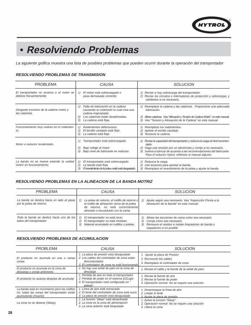
28
• Resolviendo ProblemasLa siguiente gráfica muestra una lista de posibles problemas que pueden ocurrir durante la operación del transportador
RESOLVIENDO PROBLEMAS DE TRANSMISION
PROBLEMA CAUSA SOLUCION
El transportador no arranca o el motor sedetiene frecuentemente.
Desgaste excesivo de la cadena motriz ylas catarinas.
Funcionamiento muy ruidoso en el rodamien-to.
Motor o reductor recalentado.
La banda no se mueve estando la unidadmotriz en funcionamiento.
1) El motor está sobrecargado o pasa demasiada corriente.
1) Falta de lubricación en la cadena causando su extensión lo cual crea una cadena inapropiada.
2) Los catarinas están desalineadas.3) La cadena está floja.
1) Rodamientos defectuosos.2) El tornillo candado está flojo.3) La cadena está floja.
1) Transportador está sobrecargado.
2) Bajo voltaje al motor.3) Bajo nivel de lubricante en reductor.
1) El transportador está sobrecargado.2) La banda está floja.3) El revestimiento de la polea motriz está desgastado.
1) Revise si hay sobrecarga del transportador.2) Revise los circuitos e interruptores de protección y sobrecarga, y
cámbielos si es necesario.
1) Reemplaze la cadena y las catarinas. Proporcione una adecuadalubricación.
2) Alinee catarinas. Vea “Alineación y Tensión de Cadena Motriz” en este manual.3) Vea “Tension y Alineación de la Cadena” en este manual.
1) Reemplaze los rodamientos.2) Apriete el tornillo candado.3) Tensione la cadena.
1) Revise la capacidad del transportador y reduzca la carga al nivel recomen-dado.
2) Haga una revisión por un electricista y corrija si es necesario.3) Vuelva a lubricar de acuerdo a las recomendaciones del fabricante.
Para el reductor Hytrol, refiérase al manual adjunto.
1) Reduzca la carga.2) Use tensores para apretar la banda.3) Reemplace el revestimiento de la polea y ajuste la banda.
RESOLVIENDO PROBLEMAS EN LA ALINEACION DE LA BANDA MOTRIZ
PROBLEMA CAUSA SOLUCION
La banda se desliza hacia un lado al pasarpor la polea de retorno.
Toda la banda se desliza hacia uno de loslados del transportador.
1) La polea de retorno, el rodillo de retorno o el rodillo de alineación cerca de la polea de retorno, no está correctamente alineado o escuadrado con la cama.
1) El transportador no está recto.2) El transportador no está nivelado.3) Material acumulado en rodillos o poleas.
1) Ajuste según sea necesario. Vea “Inspección Previa a la Alineación de la Banda” en este manual.
1) Alinee las secciones de cama como sea necesario.2) Corrija como sea necesario.3) Remueva el residuo e instale limpiadores de banda o
raspadores si es posible.
RESOLVIENDO PROBLEMAS DE ACUMULACION
PROBLEMA CAUSA SOLUCION
El producto no acumula en una o variaszonas.
El producto no acumula en la zona de descarga o zonas anteriores
El producto no avanza despúes de acumular
La banda está en movimiento pero los rodillosno; todas las zonas del transportador estánacumulando (muerto)
La zona no se detiene (Sleep).
1. La placa de presión está desajustada2. Los cables del controlador de zona están
desconectados3. El controlador de zona no está funcionando1. No hay una señal de paro en la zona de
descarga1. Pérdida de aire en todo el transportador2. Pérdida de poder en el sistema EZLogic 3. El transportador está configurado en “
asleep”1. Línea de aire está enroscada2. El lente del controlador de zona está sucio3. La placa de presión está desajustada1. La función “sleep” está desactivada2. La zona es la zona de alimentación3. La zona anterior está bloqueada
1. Ajuste la placa de Presión2. Reconecte los cables3. Reemplace el controlador de zona
1. Revise el cable y la fuente de la señal de paro
1. Revise la fuente de aire2. Revise la fuente de poder3. Operación normal- No se require una solución
1. Desenrosque la línea de aire2. Limpie el lente3. Ajuste la placa de presión1. Active la función “Sleep”2. Operación normal- No se require una solución3. Libere la zona

29
l How to Order Replacement PartsIncluded in this manual are parts drawings with completereplacement parts lists. Minor fasteners, such as nutsand bolts, are not included.
When ordering replacement parts:Contact Dealer from whom conveyor was purchased ornearest HYTROL Distributor.Give Conveyor Model Number and Serial Number orHYTROL Factory Order Number.Give Part Number and complete description from PartsList.If you are in a breakdown situation, tell us.
1. . .
2. . .
3. . .
4. . .
l Planned Maintenance Checklist
Check NoiseCheck TemperatureCheck Mounting BoltsCheck NoiseCheck TemperatureCheck Oil LevelCheck TrackingCheck TensionCheck LacingCheck NoiseCheck Mounting BoltsCheck TensionLubricateCheck for wearCheck for wearCheck Set Screws & KeysGeneral Check: All looseBolts, etc., tightened
COMPONENT SUGGESTED ACTION SCHEDULEWeekly QuarterlyMonthly
MOTOR
REDUCER
DRIVE CHAIN
SPROCKETS
BELT
BEARINGS(Pulleys & Rollers)
STRUCTURAL
The following is a general maintenance checklist which cov-ers the major components of your conveyor. This will behelpful in establishing a standard maintenance schedule.
La siguiente es una lista de verificación de mantenimientopreventivo, la cual cubre los principales componentes de sutransportador. Esta lista le será útil para establecer un pro-grama de mantenimiento estándar.
HYTROL Serial Number(Located near Drive onPowered Models).
Revisar el RuidoRevisar la TemperaturaRevisar los Tornillos de MontajeRevisar el RuidoRevisar la TemperaturaRevisar lel Nivel de AceiteRevisar la AlineaciónRevisar la TensiónRevisar al EnlaceRevisar el RuidoRevisar los Tornillos de MontajeRevisar la TensiónLubricarRevisar el DesgasteRevisar el DesgasteRevisara los Tornillos de MontajeRevisión General: Tornillos,Sueltos, etc.
COMPONENTE SUGERENCIA HORARIOSemanal TrimestralMensual
MOTOR
REDUCTOR
CADENA MOTRIZ
CATARINAS
BANDA
RODAMIENTOS(POLEAS Y RODILLOS)
ESTRUCTURA
l Lista de Mantenimiento Preventivo
Número de Serie HYTROL(Localizado cerca a laUnidad Motriz en los modelos motorizados).
l Como Ordenar Partes de RepuestoLos dibujos de las partes con listas completas de laspartes de repuesto están incluidos en este manual.Aseguradores menores como tornillos y tuercas no estánincluidas.
Para ordenar partes de repuesto:
NOTA: Revise los tornillos tensores después de lasprimeras 24 horas de operación.
Contacte el vendedor que le vendió el transporta-dor o el distribuidor de Hytrol mas cercano.Proporcione el Modelo del Transportador y elNúmero de Serie o Número de la Orden de Planta.Proporcione el Número de las partes y descripcióncompleta que aparece en la Lista de Partes.Si está en una situación crítica, comuníquese connosotros inmediatamente.
1. . .
2. . .
3. . .
4. . .
NOTE: Check Set Screws after the first 24 Hours of oper-ation.
Hytrol ConveyorHytrol ConveyorCompany, Inc.Company, Inc.
JONESBORO, ARKANSAS
ModelXX
SERIAL # 978747

S P
H
R A L
H G
U
P
FLOW
A
A
1843
4140
1
24
17
28
36
344653
22
51
49
20
54
22
51
49
30
54
38 44
15
21
10
9
42
276
5
7
35
45
25
2637
14 39 29 5548 52
16
31
133
12
223
33
4
11
47
8
19
50 50
SECTION B-B(SECCIÓN B-B)
SECTION A-A(SECCIÓN A-A)
A
A
B
B
Model 25-LREZ Parts DrawingDibujo de Partes del Modelo 25-LREZ
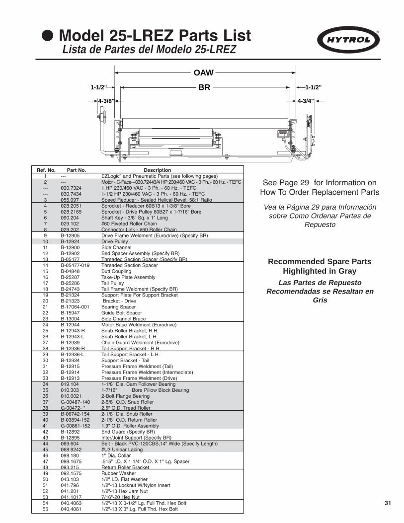
31
Ref. No. Part No. Description1 --- EZLogic® and Pneumatic Parts (see following pages)2 --- Motor - C-Face---030.72443/4 HP 230/460 VAC - 3 Ph. - 60 Hz. - TEFC--- 030.7324 1 HP 230/460 VAC - 3 Ph. - 60 Hz. - TEFC--- 030.7434 1-1/2 HP 230/460 VAC - 3 Ph. - 60 Hz. - TEFC3 055.097 Speed Reducer - Sealed Helical Bevel, 58:1 Ratio4 028.2051 Sprocket - Reducer 60B13 x 1-3/8" Bore5 028.2165 Sprocket - Drive Pulley 60B27 x 1-7/16" Bore6 090.204 Shaft Key - 3/8" Sq. x 1" Long7 029.102 #60 Riveted Roller Chain8 029.202 Connector Link - #60 Roller Chain9 B-12905 Drive Frame Weldment (Eurodrive) (Specify BR) 10 B-12924 Drive Pulley 11 B-12900 Side Channel 12 B-12902 Bed Spacer Assembly (Specify BR)13 B-05477 Threaded Section Spacer (Specify BR) 14 B-05477-019 Threaded Section Spacer 15 B-04848 Butt Coupling 16 B-25287 Take-Up Plate Assembly 17 B-25286 Tail Pulley 18 B-24743 Tail Frame Weldment (Specify BR)19 B-21324 Support Plate For Support Bracket20 B-21323 Bracket - Drive 21 B-17064-001 Bearing Spacer 22 B-15947 Guide Bolt Spacer 23 B-13004 Side Channel Brace 24 B-12944 Motor Base Weldment (Eurodrive) 25 B-12943-R Snub Roller Bracket, R.H. 26 B-12943-L Snub Roller Bracket, L.H. 27 B-12939 Chain Guard Weldment (Eurodrive) 28 B-12936-R Tail Support Bracket - R.H. 29 B-12936-L Tail Support Bracket - L.H. 30 B-12934 Support Bracket - Tail 31 B-12915 Pressure Frame Weldment (Tail) 32 B-12914 Pressure Frame Weldment (Intermediate) 33 B-12913 Pressure Frame Weldment (Drive) 34 019.104 1-1/8" Dia. Cam Follower Bearing 35 010.303 1-7/16" Bore Pillow Block Bearing 36 010.0021 2-Bolt Flange Bearing 37 G-00487-140 2-5/8" O.D. Snub Roller 38 G-00472- * 2.5" O.D. Tread Roller 39 B-06742-154 2-1/8" Dia. Snub Roller 40 B-03894-152 2-1/8" O.D. Return Roller41 G-00861-152 1.9" O.D. Roller Assembly 42 B-12892 End Guard (Specify BR)43 B-12895 Inter/Joint Support (Specify BR)44 069.604 Belt - Black PVC-120CBS,14" Wide (Specify Length)45 068.9242 #U3 Unibar Lacing46 098.180 1" Dia. Collar 47 098.1675 .515" I.D. X 1 1/4" O.D. X 1" Lg. Spacer 48 093.215 Return Roller Bracket 49 092.1575 Rubber Washer 50 043.103 1/2" I.D. Flat Washer 51 041.796 1/2"-13 Locknut W/Nylon Insert 52 041.201 1/2"-13 Hex Jam Nut 53 041.1017 7/16"-20 Hex Nut 54 040.4063 1/2"-13 X 3-1/2" Lg. Full Thd. Hex Bolt 55 040.4061 1/2"-13 X 3" Lg. Full Thd. Hex Bolt
1 39 35
56
38
62
1-1/2"
OAW
BR 1-1/2"
4-3/8" 4-3/4"
l Model 25-LREZ Parts ListLista de Partes del Modelo 25-LREZ
See Page 29 for Information onHow To Order Replacement Parts
Recommended Spare PartsHighlighted in Gray
Vea la Página 29 para Informaciónsobre Como Ordenar Partes de
Repuesto
Las Partes de RepuestoRecomendadas se Resaltan en
Gris
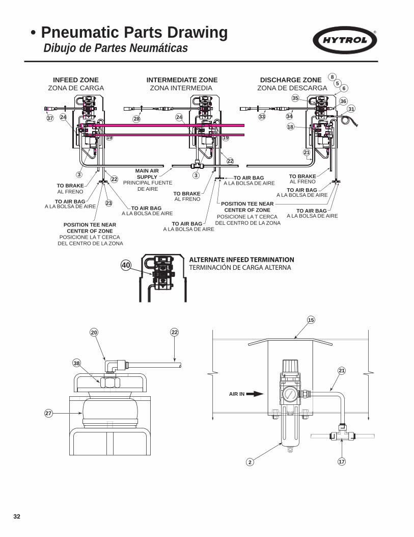
32
24
3536
31
18
TO AIR BAG
TO AIR BAG
TO BRAKETO AIR BAG
TO AIR BAG
POSITION TEE NEARCENTER OF ZONE
21
19
3
TO BRAKE
MAIN AIRSUPPLY
23TO AIR BAG
TO AIR BAG
POSITION TEE NEARCENTER OF ZONE
19
TO BRAKEAL FRENO
A LA BOLSA DE AIREAL FRENO
AL FRENO
A LA BOLSA DE AIRE
PRINCIPAL FUENTEDE AIRE
A LA BOLSA DE AIRE
A LA BOLSA DE AIRE
A LA BOLSA DE AIREA LA BOLSA DE AIRE
POSICIONE LA T CERCA DEL CENTRO DE LA ZONA
POSICIONE LA T CERCA DEL CENTRO DE LA ZONA
22
37 28
INFEED ZONEZONA DE CARGA ZONA INTERMEDIA ZONA DE DESCARGA
INTERMEDIATE ZONE DISCHARGE ZONE
223
24 33 34
65
8
AIR IN
15
2
21
17
38
22
27
20
• Pneumatic Parts DrawingDibujo de Partes Neumáticas
40ALTERNATE INFEED TERMINATIONTERMINACIÓN DE CARGA ALTERNA
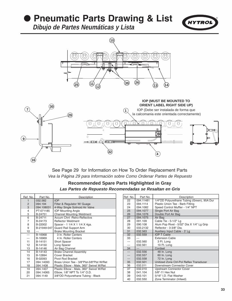
33
l Pneumatic Parts Drawing & ListDibujo de Partes Neumáticas y Lista
25 11 39
10
2613 1412
DC
AC
730
9
1
16
IOP (Debe ser instalada de forma que la calcomania este orientada correctamente)
IOP (MUST BE MOUNTED TO ORIENT LABEL RIGHT SIDE UP)
32
29
4
See Page 29 for Information on How To Order Replacement Parts
Recommended Spare Parts Highlighted in Gray
Vea la Página 29 para Información sobre Como Ordenar Partes de Repuesto
Las Partes de Repuesto Recomendadas se Resaltan en Gris
Ref. No. Part No. Description1 032.582 IOP2 094.194 Filter & Regulator W/ Guage3 094.108031 4-Way Single Solinoid Air Valve4 PT-071185 IOP Mounting Angle5 B-24751 Channel Mounting Weldment6 B-24711 Accum Chnl -Retro-Reflective7 B-24173 Reflector Weldment8 B-22002 Spacer - 1 1/4 X 1 1/4 X 4ga.9 B-21949-047 Guard Rail Support Arm10 --- Brake Mounting Bracket--- B-16968 3 In. Roller Centers--- B-16969 4 In. Roller Centers11 B-14151 Short Spacer12 B-14150 Long Spacer13 B-14146 Air Bag Channel14 B-14143 Brake Channel Assembly15 B-12894 Cover Bracket16 B-02093 Pivot Rod Bracket17 094.14093 Brass Union Tee - 3/8"Plst-3/8"Plst W/Ret18 094.1408 Plastic Elbow - Male, 360° Swivel W/Ret19 094.1407 Plastic Elbow - Male, 360° Swivel W/Ret20 094.14065 Elbow, 1/8" NPT To 1/4" O.D.21 094.1149 3/8"OD Polyurethane Tubing - Black
Ref. No. Part No. Description22 094.11481 1/4"OD Polyurethane Tubing (Green), 95A Dur23 094.1114 Plastic Union Tee - Barb Fitting24 094.1082 Speed Control Muffler - 1/4" NPT25 094.1077 Single Port Air Bag26 094.1076 Double Port Air Bag27 094.1075 Air Bag28 091.109 Cable Tie - 5-1/2" Lg29 090.108 Alum Pop Rivet - 5/32" Dia X 1/4" Lg Grip30 033.2132 Reflector - 3-3/8" Dia.31 032.563 Auxiliary Input Cable - 3' Lg32 032.559 IOP T Cable33 --- Extension Cable--- 032.560 3 Ft. Long--- 032.561 10 Ft. Long34 --- Cordset--- 032.556 48 In. Long--- 032.557 60 In. Long--- 032.558 72 In. Long35 032.501 Unitized Zone Ctrl-Pol Reflex Transducer36 032.011 Downstream Connector Cover 37 032.010 Upstream Connector Cover 38 041.104 5/8"-11 Hex Nut39 043.101 5/16" I.D. Flat Washer40 032.550 Zone Terminator (Infeed)

34
l Notes

35
l Notes
HYTROL CONVEYOR COMPANY, INC.2020 Hytrol Drive
Jonesboro, Arkansas 72401U.S.A.
Phone: (870) 935-3700www.hytrol.com
EFFECTIVE APRIL 2008Printed by Master Printing 4/08