MAINTENANCE - greeonline.com · U-Match Series DC Inverter Service Manual 70 MAINTENANCE 1 TROUBLE...
26
U-Match Series DC Inverter Service Manual 69 MAINTENANCE
Transcript of MAINTENANCE - greeonline.com · U-Match Series DC Inverter Service Manual 70 MAINTENANCE 1 TROUBLE...

U-Match Series DC Inverter Service Manual
69
MAINTENANCE

U-Match Series DC Inverter Service Manual
70
MAINTENANCE
1 TROUBLE TABLE 1.1 Main Control Malfunction
Table 1 Fault Display on Indoor Wired Controller
No. Error
code
Malfunction
name
Origin of
malfunction
signal
Control description
1 E1 High pressure
protection
High pressure
switch
When outdoor unit detects the high pressure switch is cut off
for 3s successively, high pressure protection will occur. All
the loads (except the 4-way valve in heating mode) will be
switched off. In this case, all the buttons and remote control
signals except ON/OFF button will be disabled and cannot
be recovered automatically. Switch off the unit or
re-energize the unit after cutting off power to eliminate this
protection.
2 E2 Freeze
protection
Indoor
evaporator
temperature
sensor
If detecting that the evaporator temperature is lower than
protective temp. value after the unit has been running for a
period of time under cooling or dry mode, the unit will report
this fault, in which case the compressor and outdoor fan
motor will be stopped. The unit will not run until evaporator
temperature is higher than the protective temp. value and
the compressor is stopped for 3min.
3 E3
Low pressure
protection
Low pressure
switch
If it is detected within 30s successively that the low-pressure
switch is cut off under ON or standby state, the unit will
report low pressure protection. If the fault occurs
successively 3 times within 30min, the unit cannot be
recovered automatically.
Refrigerant
lacking
protection
If the unit reports system refrigerant lacking within 10min
after turning on the unit, the unit will stop operation. If the
fault occurs successively 3 times, the unit cannot be
recovered automatically.
Refrigerant
recycling
mode
If enter refrigerant recycling mode through special
operation, E3 will be displayed. After exiting refrigerant
recycling mode, the code will disappear.
4 E4
Compressor
high
discharge
temperature
protection
Compressor
discharge
temperature
is high
If outdoor unit detects that the discharge temperature is
higher than protective temp. value, the unit will report high
discharge temperature protection. If the protection occurs
over 6 times, the unit cannot be recovered automatically.
Switch off the unit or re-energize the unit after cutting off
power to eliminate this protection.
6 E6
Communicati
on
malfunction
Communicati
on between
indoor and
outdoor
mainboard
If the outdoor unit does not receive data from indoor unit,
communication malfunction will be reported. If there is
communication abnormity between display board and indoor
unit, communication malfunction will be reported too.
8 E8
Malfunction of
indoor fan
motor
Indoor fan
motor
If the indoor unit does not receive signal from indoor fan
motor for 30s successively when the fan motor is operating,
indoor fan motor malfunction will be reported. In this case,
the unit can automatically resume operation after stopping.
If the malfunction occurs 6 times within one hour, the unit
cannot be recovered automatically. Switch off the unit or
re-energize the unit after cutting off power to eliminate this
malfunction.

U-Match Series DC Inverter Service Manual
71
No. Error
code
Malfunction
name
Origin of
malfunction
signal
Control description
9 E9 Full water
protection
Water level
switch
If cut-off of water level switch is detected for 8s successively
once energized, the system will enter full water protection.
In this case, switch off the unit and then switch it on to
eliminate this malfunction.
10 F0
Malfunction of
indoor
ambient
temperature
sensor at air
return port
Indoor
ambient
temperature
sensor
If the indoor ambient temperature sensor is detected of
open circuit or short circuit for 5s successively, indoor
ambient temperature sensor malfunction will be reported.
The unit can automatically resume operation after the
malfunction disappears. If indoor ambient temperature
sensor malfunction occurs in fan mode, only the error code
is displayed and the indoor unit can work normally.
11 F1
Malfunction of
evaporator
temperature
sensor
Evaporator
temperature
sensor
If the indoor evaporator temperature sensor is detected of
open circuit or short circuit for 5s successively, evaporator
temperature sensor malfunction will be reported. The unit
can automatically resume operation after the malfunction
disappears. If evaporator temperature sensor malfunction
occurs in fan mode, only the error code is displayed and the
indoor unit can work normally.
12 F2
Malfunction of
condenser
temperature
sensor
Condenser
temperature
sensor
If the outdoor condenser temperature sensor is detected of
open circuit or short circuit for 5s successively, condenser
temperature sensor malfunction will be reported. The unit
can automatically resume operation after the malfunction
disappears. If condenser temperature sensor malfunction
occurs in fan mode, only the error code is displayed and the
indoor unit can work normally.
13 F3
Malfunction of
outdoor
ambient
temperature
sensor
Outdoor
ambient
temperature
sensor
If the outdoor ambient temperature sensor is detected of
open circuit or short circuit for 5s successively, outdoor
ambient temperature sensor malfunction will be reported.
The unit can automatically resume operation after the
malfunction disappears. If outdoor ambient temperature
sensor malfunction occurs in fan mode, only the error code
is displayed and the indoor unit can work normally.
14 F4
Malfunction of
discharge
temperature
sensor
Discharge
temperature
sensor
If the outdoor discharge temperature sensor is detected of
open circuit or short circuit for 5s successively after the
compressor has been operating for 3min, outdoor discharge
temperature sensor malfunction will be reported. The unit
can automatically resume operation after the malfunction
disappears.
15 F5
Malfunction
wired
controller
temperature
sensor
Wired
controller
If the wired controller detects open circuit or short circuit of
its temperature sensor for 5s successively, wired controller
temperature sensor malfunction will be reported.
18 ee
Malfunction of
outdoor drive
memory chip
Outdoor drive
board
If the memory chip of outdoor drive board is broken, the unit
cannot be started. The unit cannot be recovered
automatically. If the malfunction cannot be eliminated after
switching off the unit and then energizing the unit for several
times, please replace the outdoor drive board.
20 H3
Compressor
overload
protection
Compressor
overload
switch
If it is detected within 3s successively that the overload
switch is cut off under ON or standby state, the unit will
report overload protection. If the fault occurs successively 3
times, the unit cannot be recovered automatically. Switch off
the unit or re-energize the unit after cutting off power to
eliminate this protection.

U-Match Series DC Inverter Service Manual
72
No. Error
code
Malfunction
name
Origin of
malfunction
signal
Control description
21 H4 Overload
protection
Evaporator
temperature,
condenser
temperature
If outdoor unit detects that the tube temperature is higher
than protective temp. value, the unit will report overload
protection. The unit will not restart operation until tube
temperature is lower than the protective temp. value and the
compressor is stopped for 3min. If the protection occurs
over 6 times, the unit cannot be recovered automatically.
Switch off the unit or re-energize the unit after cutting off
power to eliminate this protection.
23 H6
Malfunction of
outdoor fan
motor
Outdoor fan
motor
If the outdoor unit does not receive signal from outdoor fan
motor for 30s successively when the fan motor is operating,
outdoor fan motor malfunction will be reported. In this case,
the unit can automatically resume operation after stopping.
If the malfunction occurs 6 times within one hour, the unit
cannot be recovered automatically. Switch off the unit or
re-energize the unit after cutting off power to eliminate this
malfunction.
32 U7
Direction
changing
malfunction of
4-way valve
4-way valve
After the compressor starts operation in heating mode, if the
outdoor unit detects the difference between evaporator
temperature and indoor ambient temperature is lower than
the protective value for 10min successively, direction
changing malfunction of 4-way valve will be reported and
the outdoor unit will stop operation. The unit can
automatically resume operation in the first two malfunctions.
If the malfunction occurs 3 times, the unit cannot be
recovered automatically. Switch off the unit or re-energize
the unit after cutting off power to eliminate this malfunction.
35 P6
Communicati
on
malfunction
between main
control and
drive
Communicati
on between
main control
board and
drive board
If the outdoor main control board does not receive data from
drive board, communication malfunction between main
control and drive will be reported. This malfunction can be
eliminated automatically.
47 EE
Malfunction of
outdoor main
control
memory chip
Outdoor main
control board
If the memory chip of outdoor main control board is broken,
the unit cannot be started. The unit cannot be recovered
automatically. If the malfunction cannot be eliminated after
switching off the unit and then energizing the unit for several
times, please replace the outdoor main control board.

U-Match Series DC Inverter Service Manual
73
1.2 Description of Drive Malfunction
Main board dual 8 numeral tube Display Codes for Outdoor Unit of 24~60k
Malfunction Item Indoor Unit Display Outdoor unit display of dual 8
numeral tube
DC busbar over-voltage protection PH PH
IPM or PFC over-temperature protection P8 P8
Current sense circuit error Pc Pc
IPM or PFC temperature sensor error P7 P7
Compressor current protection P5 P5
DC busbar under-voltage protection PL PL
Compressor startup failure Lc Lc
Drive module reset P0 P0
Compressor motor desynchronizing H7 H7
Phase loss Ld Ld
Drive-to-main-control communication error P6 P6
IPM protection H5 H5
Compressor overload protection H3 H3
AC current protection (input side) PA PA
Charging circuit error PU PU
PFC protection HC HC
DC fan error H6 H6
Input AC voltage abnormality PP PP
Driving board memory chip error ee ee

U-Match Series DC Inverter Service Manual
74
2 FLOW CHART OF TROUBLESHOOTING
2.1 Troubleshooting Flow Chart of Main Control Malfunction
E1 High Pressure Protection

U-Match Series DC Inverter Service Manual
75
E2 Freeze Protection
Freeze protection is normal protection but not abnormal malfunction. If freeze protection occurs
frequently during operation, please check if the indoor filter is with filth blockage or if the indoor air outlet is
abnormal. The user is required to clean the filter, check the air outlet and air return pipe periodically to
ensure smooth air return and air outlet.
E3 stands for three statuses:
(1) Low pressure protection;
(2) Refrigerant lacking protection;
(3) Refrigerant recycling mode;
1) If enter refrigerant recycling mode through special operation, the displayed E3 is not an error
code. It will be eliminated when exiting refrigerant recycling mode.
2) If you do not want to have refrigerant lacking protection, you can enter the debugging mode
through wired controller and then cancel the refrigerant lacking protection mode.

U-Match Series DC Inverter Service Manual
76
E4 Discharge Protection
E6 Communication Malfunction
Communication
malfunction
Check if the
communication wire between
indoor unit and outdoor unit is
connected well
Check if there is
open circuit in the communication
wire between indoor unit and
outdoor unit
Reconnect the
communication
wire
Replace the
communication
wire
Check if the
outdoor unit is energized
Energize the
outdoor unit
Replace the mainboard
Yes
Yes
No
No
No
Yes
U-Match Series DC Inverter Service Manual
77
E9 Full Water Protection
E9 protection
If the unit is
installed with
water pump
No
Yes
Replace the water pump
Short circuit the full water
protection interface on indoor
mainboard according to the circuit
diagram
Check if the
water pump
works normally
No
Replace the full water switch
or make sure the float of full
water switch works normally
Yes
F0 Malfunction of Indoor Ambient Temperature Sensor
Malfunction of
indoor ambient
temperature
sensor
Check if the
indoor ambient temperature
sensor on mainboard is inserted
on the needle
stand correctly
Disconnect
the temperature sensor and
measure if its resistance is
normal
Correctly insert the
temperature sensor
on the needle stand
Replace the
temperature sensor
Replace the indoor
mainboard
Yes
No
No
Yes

U-Match Series DC Inverter Service Manual
78
F1 Malfunction of Evaporator Temperature Sensor
Malfunction of
evaporator
temperature
sensor
Check if the evaporator
temperature sensor on
mainboard is inserted on the
needle stand correctly
Disconnect
the temperature sensor and
measure if its resistance is
normal
Correctly insert the
temperature
sensor on the
needle stand
Replace the
temperature
sensor
Replace the
indoor
mainboard
Yes
No
No
Yes
F2 Malfunction of Condenser Temperature Sensor
Malfunction of
condenser
temperature
sensor
Check if the condenser
temperature sensor on
mainboard is inserted on the
needle stand correctly
Disconnect
the temperature sensor and
measure if its resistance is
normal
Correctly insert the
temperature sensor
on the needle stand
Replace the
temperature sensor
Replace the
outdoor
mainboard
Yes
No
No
Yes

U-Match Series DC Inverter Service Manual
79
F3 Malfunction of Outdoor Ambient Temperature Sensor
Malfunction of
outdoor ambient
temperature
sensor
Check
if the outdoor ambient
temperature sensor on mainboard
is inserted on the needle stand
correctly
Disconnect
the temperature sensor and
measure if its resistance is
normal
Correctly insert the
temperature sensor on
the needle stand
Replace the
temperature sensor
Replace the
outdoor
mainboard
Yes
No
No
Yes
F4 Malfunction of Discharge Temperature Sensor
Malfunction of
discharge
temperature
sensor
Check if the
discharge temperature sensor on
mainboard is inserted on the
needle stand correctly
Disconnect
the temperature sensor and
measure if its resistance is
normal
Correctly insert the
temperature sensor
on the needle stand
Replace the
temperature sensor
Replace the
outdoor
mainboard
Yes
No
No
Yes

U-Match Series DC Inverter Service Manual
80
F5 Malfunction of Wired Controller Temperature Sensor
Malfunction of
wired controller
temperature
sensor
Replace the
wired controller
H6 Malfunction of Outdoor Fan Motor
Malfunction of
discharge
temperature
sensor
Check if the
control wire of outdoor fan motor is
connected on the outdoor
mainboard correctly
Replace the
outdoor fan motor and then
restart the unit to see if there still
is malfunction of outdoor fan
motor
Correctly connect the
control wire of fan motor
on the mainboard
Operate the unit with
the new motor
Replace the
outdoor
mainboard
Yes
No
No
Yes
E8 Malfunction of Indoor Fan Motor
Malfunction of
indoor fan motor
Check if the
control wire of indoor fan motor is
connected on the outdoor
mainboard correctly
Replace
the indoor fan motor and then
restart the unit to see if there still
is malfunction of indoor
fan motor
Correctly connect the
control wire of fan motor
on the mainboard
Operate the unit with
the new motor
Replace the
indoor
mainboard
Yes
No
No
Yes

U-Match Series DC Inverter Service Manual
81
2.2 Troubleshooting Flow Chart of Drive Malfunction
Note: For Outdoor Unit Drive (Inverter) by Single-phase Motor
P0 Drive module reset
P7 IPM or PFC temperature sensor error
PA AC current protection (input side)
PC Current sense circuit error
HC PFC protection(42\48k\60k only)
P0、P7、PA、Hc or
PC is displayed on
the wired controller
P0、P7、PA、Hc or
PC is displayedin the
mainboard 88
Indicating Lamp
Replace the
mainboard
Work Normally
P8 IPM or PFC over-temperature protection
P8 is displayed on
the wired controller
P8 is displayed in the
mainboard 88
Indicating lamp
Is the
IPM or PFC module
of mainboard
tightened?
No
Work normally
Replace the
mainboard
Yes
Tighten the IPM
or PFC module

U-Match Series DC Inverter Service Manual
82
PH DC busbar over-voltage protection
PL DC busbar under-voltage protection
PH or PL is displayed on
the wired controller
PH or PL is displayed in
the mainboard 88
indicating lamp
Is input voltage
ranged from 185VAC
to 264VAC?Yes
Replace the
mainboard.Does
it work normally?
No
Replace the
compressor
Work
normally
Yes
Please cut off the
power and notify the
power company.
No
P6 Drive-to-main-control communication error
Lc Compressor Startup Failure
Lc is displayed on
the wired controller
Lc is displayed in
the mainboard 88
indicating lamp
Replace the
mainboard. Does it
work normally?
Replace the
compressor
Work normally
Yes
No

U-Match Series DC Inverter Service Manual
83
P5 Compressor current protection
H7 Compressor motor desynchronizing
H5 IPM protection
Ld Phase loss
P5, H7, H5 or Ld is displayed
in the mainboard 88
indicating lamp
Is the compressor
phase sequence right?
Yes
Replace the mainboard.
Does it work normally?
No
Replace the compressor Work normally
Yes
adjust the
compressor
phase sequence
Is the compressor wire
terminals tightened?
Tighten the
compressor wire
terminals
Yes
No
No
P5, H7, H5 or Ld is displayed
on the wired controller
PU Charging circuit error
PU is displayed on
the wired controller
PU is displayed in
the mainboard 88
indicating lamp
Is the PFC wire
tightened or is the
sequence right?
Tighten the PFC
wire or adjust the
sequence
Replace the
mainboard
Yes No
Work normally

U-Match Series DC Inverter Service Manual
84
ee driving board chip error
Yes
Yes
ee is displayed
on the wired
controller
Is the
jumper
loose?
Work Normally
Tighten the
jumper
Replace the
mainboard
No
H6 DC fan error
H6 is displayed in the
mainboard 88 indicating
lamp
Is the motor phase
sequence right?
Yes
Replace the
mainboard.Does it
work normally?
No
Replace the outdoor fan Work normally
Yes
Adjust the motor
phase sequence
Is the Fan wire terminal
loose?Tighten the fan
wiring terminal
Yes
No
No
H6 is displayed on the wired
controller

U-Match Series DC Inverter Service Manual
85
2.3 Interface
Outdoor units Main Control Board
NO. SILK-SCREEN INTERFACE INTERFACE INSTRUCTION
1 AC-L Live wire input Live wire input
2 AC-N Neutral wire input Neutral wire input
3 PWR 1 Control power output[1- DC bus
voltage,3- GND]
Power supply interface to the
drive
1-pin: DC bus voltage
3-pin: DC bus GND
4 DC_MOTOR2
DC fan motor2
1-pin: Power supply of fan motor
3-pin: Fan GND
4-pin: +15V
5-pin: Signal control
6-pin: NC
Interface of DC fan motor
1-pin: DC bus voltage
2-pin: Suspended
3-pin: DC bus GND
4-pin: +15V
5-pin: Control signal input
6-pin: Not connected
5 DC_MOTOR1
DC fan motor1
1-pin: Power supply of fan motor
3-pin: Fan GND
4-pin: +15V
5-pin: Signal control
6-pin: Signal Feedback
Interface of DC fan motor
1-pin: DC bus voltage
2-pin: Suspended
3-pin: DC bus GND
4-pin: +15V
5-pin: Control signal input
65-pin: DC fan motor feedback
6 CN3 Control power output[1-GND、2-18V、
3-15V]
Power supply interface to the
drive
1-pin: GND
2-pin: +18V
3-pin: +15V
7 COMM1 Communication line [1-3.3V、2-TX、
3-RX、4-GND]
Communication needle stand of
main control drive
1-pin: +3.3V, 2-pin: TXD

U-Match Series DC Inverter Service Manual
86
3-pin: RXD, 4-pin: GND
8 CN2 Communication line with1-pin GND,
2-pin B and 3-pinA)
Communication needle stand
with indoor unit
1-pin: GND, 2-pin: B,
3-pin: A
9 CN1 Communication line with 1-pin plus
12V, 2-pin B, 3-pin A and 4-pin GND
Communication interface
(reserved):
1-pin: +12V, 2-pin: B,
3-pin: A, 4-pin: GND
10 H-PRESS High pressure switch for fan speed
adjustment
Pressure protection switch for
fan speed adjustment
11 HPP High pressure switch for system
protection (obligate)
Interface of high pressure
protection
12 LPP Low pressure switch for system
protection (obligate)
Interface of low pressure
protection
13 OVC-COMP Compressor overload protection Interface of compressor
overload protection
14 T-SENSOR2
1&2 pin: Tube sensor
3&4 pin: Ambient temperature
5&6 pin: Air discharge
1&2 pin: Case temperature
sensor
3&4 pin: Ambient temperature
sensor
5&6 pin: Discharge temperature
sensor
15 FA
Electronic expansion valve line
1 to 4-pin: Drive impulse output;5-pin:
+12V;
Interface of electronic
expansion valve:
1 to 4-pin: Drive impulse output;
5-pin: +12V;
16 HEAT Compressor electrical heater Compressor electric heating
belt
17 VA-1 Chassis electrical heater Chassis electric heating belt
18 4V 4-way valve 4-way valve
GUHD24NS3GO/GUHD36NS3GO
(1). Driving Board
2 3 41 5
6
7
8910131415 1112

U-Match Series DC Inverter Service Manual
87
No. Printing Interface No. Printing Interface
1 L2_2 PFC induction wire (blue) 2 L1_1 PFC induction wire (brown)
3 N Neutral wire input (white) 4 AC-L Live wire input (red)
5 COMM/COMM1 Communication interface 6 JTAG1 (Reserved)
7 PWR Control power input 8 DC-BUS1 Bus electric discharging
interface (for testing)
9 L2-1 PFC induction wire (yellow) 10 L1-2 PFC induction wire (white)
11 P-OUT (Reserved) 12 G-OUT (Reserved)
13 W Compressor Phase W 14 V Compressor Phase V
15 U Compressor Phase U
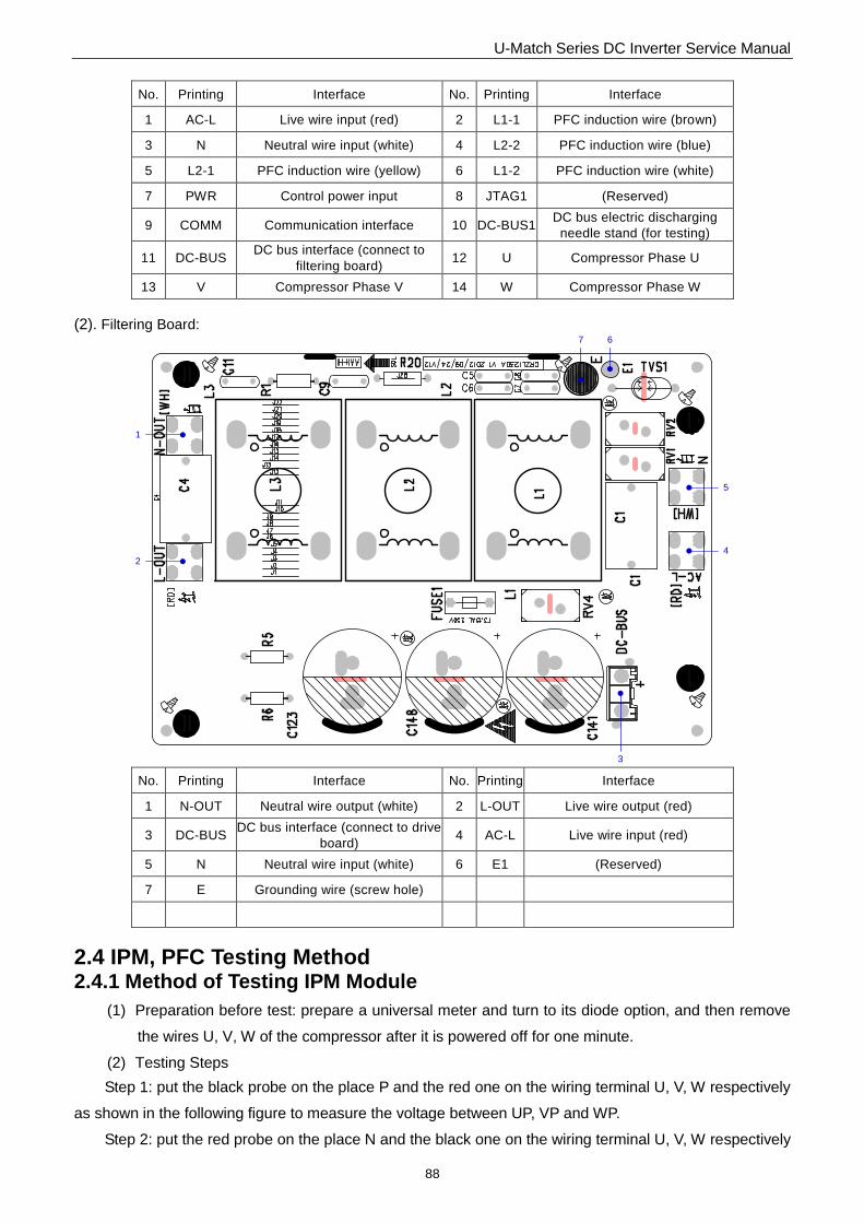
(2). Filtering Board
1
2
35
4
6
7
No. Printing Interface No. Printing Interface
1 N-OUT1 Neutral wire output 1 (white) 2 N-OUT Neutral wire output (white)
3 L-OUT Live wire output (red) 4 E1 Grounding wire
5 E2 (Reserved) 6 AC-L Live wire input (red)
7 AC-N Neutral wire input (white)
GUHD42NS3GO/GUHD48NS3GO/GUHD60NS3GO
(1). Drive Board: 11
1
8
2
3
4
5
6
7
9
10
121314
U-Match Series DC Inverter Service Manual
88
No. Printing Interface No. Printing Interface
1 AC-L Live wire input (red) 2 L1-1 PFC induction wire (brown)
3 N Neutral wire input (white) 4 L2-2 PFC induction wire (blue)
5 L2-1 PFC induction wire (yellow) 6 L1-2 PFC induction wire (white)
7 PWR Control power input 8 JTAG1 (Reserved)
9 COMM Communication interface 10 DC-BUS1 DC bus electric discharging
needle stand (for testing)
11 DC-BUS DC bus interface (connect to
filtering board) 12 U Compressor Phase U
13 V Compressor Phase V 14 W Compressor Phase W
(2). Filtering Board:
3
4
5
67
1
2
No. Printing Interface No. Printing Interface
1 N-OUT Neutral wire output (white) 2 L-OUT Live wire output (red)
3 DC-BUS DC bus interface (connect to drive
board) 4 AC-L Live wire input (red)
5 N Neutral wire input (white) 6 E1 (Reserved)
7 E Grounding wire (screw hole)
2.4 IPM, PFC Testing Method
2.4.1 Method of Testing IPM Module
(1) Preparation before test: prepare a universal meter and turn to its diode option, and then remove
the wires U, V, W of the compressor after it is powered off for one minute.
(2) Testing Steps
Step 1: put the black probe on the place P and the red one on the wiring terminal U, V, W respectively
as shown in the following figure to measure the voltage between UP, VP and WP.
Step 2: put the red probe on the place N and the black one on the wiring terminal U, V, W respectively

U-Match Series DC Inverter Service Manual
89
as shown in the following figure to measure the voltage between NU, NV and NW.
(3) If the measured voltages between UP, VP, WP, NU, NV, NV are all among 0.3V-0.7V, then it
indicates the IPM module is normal; If any measured valve is 0, it indicates the IPM is damaged.
2.4.2 Method of Testing PFC Module Short Circuit
Note: Only for GUHD42NS3GO/GUHD48NS3GO/GUHD60NS3GO
(4) Preparation before test: prepare a universal meter and turn to its diode option, and then remove
the wires L1-2, L2-1 after it is powered off for one minute.
(5) Testing Steps
Step 1: put the black probe on the place P and the red one on the wiring terminal L1-2,
L2-1respectively as shown in the following figure to measure the voltage between L1-2P and.L2-1 P.
Step 2: put the red probe on the place N and the black one on the wiring terminal L1-2,
L2-1respectively as shown in the following figure to measure the voltage between N L1-2 and NL2-1.
(6) If the measured voltages between L1-2P ,L2-1 P, N L1-2 , NL2-1 are all among 0.3V-0.7V, then it
indicates the PFC module is normal; If any measured valve is 0, it indicates the PFC is damaged.
GUHD24NS3GO/GUHD36NS3GO
\

U-Match Series DC Inverter Service Manual
90
GUHD42NS3GO/GUHD48NS3GO/GUHD60NS3GO
3 WIRING DIADRAM
3.1 Outdoor unit
The actual wiring should always refer to the wiring diagram of the unit.
Model: GUHD24NS3GO

U-Match Series DC Inverter Service Manual
91
Model: GUHD36NS3GO
Model: GUHD42NS3GO

U-Match Series DC Inverter Service Manual
92
Model: GUHD48NS3GO/GUHD60NS3GO
3.2 Indoor unit
The actual wiring should always refer to the wiring diagram of the unit.
3.2.1 Duct Type
Model: GFH24S3GI

U-Match Series DC Inverter Service Manual
93
GFH24S3G1I
Model: GFH36S3GI/GFH42S3GI/GFH48S3GI/GFH60S3GI

U-Match Series DC Inverter Service Manual
94
Model: GFH36S3G1I/GFH42S3G1I/GFH48S3G1I/GFH60S3GI