MAINTENANCE TECHNICAL SUPPORT CENTER … DBCS OSS eCBM.pdf · Time Total: See roll-ups in...
49
Web Access: http://mtsc.usps.gov This Maintenance Management Order (MMO) provides Preventive, Predictive, and Operational Maintenance Guidelines for the Delivery Bar Code Sorter Output Sub System and supersedes MMO-005-08. The acronym is DBCS/OSS and the class code is CI. The workhours indicated in the workload estimate (Attachment 1) reflect the maximum annual workhours required to maintain each system. Actual workhour requirements and the frequency of tasks are dependent on pieces processed. Therefore, PM workhour requirements will vary day-to-day based on site specific machine utilization. Management may modify task frequencies to address local conditions. The minimum maintenance skill level required to perform each task is included in the Minimum Skill Level column of each checklist. This does not preclude higher level employees from performing any of this work. Preventive Maintenance (PM) guidelines provide maintenance employees with the recommended task based maintenance activities. The Electronic Conditioned Based Maintenance (eCBM) is an abbreviated task list that represents a portion of the PM checklist. The complete master PM checklist must be accessible to all maintenance employees when performing PM and eCBM task based maintenance activities. WARNING Steps contained in this bulletin may require the use of Personal Protective Equipment (PPE). Refer to the current Electrical Work Plan (EWP) MMO for appropriate PPE requirements. MAINTENANCE TECHNICAL SUPPORT CENTER MAINTENANCE OPERATIONS / UNITED STATES POSTAL SERVICE Maintenance Management Order SUBJECT: Operational, Predictive, & Preventive Maintenance Guidelines for Delivery Bar Code Sorter Output Sub System (DBCS/OSS) using eCBM December 21, 2011 MMO-138-11 DATE: NO: FILE CODE: 2DA wbro:mm10112ak TO: Maintenance Managers DBCS/OSS Offices
Transcript of MAINTENANCE TECHNICAL SUPPORT CENTER … DBCS OSS eCBM.pdf · Time Total: See roll-ups in...

Web Access: http://mtsc.usps.gov
This Maintenance Management Order (MMO) provides Preventive, Predictive, and Operational Maintenance Guidelines for the Delivery Bar Code Sorter Output Sub System and supersedes MMO-005-08. The acronym is DBCS/OSS and the class code is CI. The workhours indicated in the workload estimate (Attachment 1) reflect the maximum annual workhours required to maintain each system. Actual workhour requirements and the frequency of tasks are dependent on pieces processed. Therefore, PM workhour requirements will vary day-to-day based on site specific machine utilization. Management may modify task frequencies to address local conditions. The minimum maintenance skill level required to perform each task is included in the Minimum Skill Level column of each checklist. This does not preclude higher level employees from performing any of this work. Preventive Maintenance (PM) guidelines provide maintenance employees with the recommended task based maintenance activities. The Electronic Conditioned Based Maintenance (eCBM) is an abbreviated task list that represents a portion of the PM checklist. The complete master PM checklist must be accessible to all maintenance employees when performing PM and eCBM task based maintenance activities.
WARNING
Steps contained in this bulletin may require the use of Personal Protective Equipment (PPE). Refer to the current Electrical Work Plan (EWP) MMO for appropriate PPE requirements.
MAINTENANCE TECHNICAL SUPPORT CENTER MAINTENANCE OPERATIONS / UNITED STATES POSTAL SERVICE
Maintenance Management Order
SUBJECT: Operational, Predictive, & Preventive Maintenance Guidelines for Delivery Bar Code Sorter Output Sub System (DBCS/OSS) using eCBM
December 21, 2011
MMO-138-11
DATE:
NO:
FILE CODE: 2DA wbro:mm10112ak TO: Maintenance Managers DBCS/OSS Offices

MMO-138-11 Maintenance Technical Support Center
2
WARNING Various products requiring Material Safety Data Sheets (MSDS) may be utilized during the performance of the procedures in this bulletin. Ensure the current MSDS for each product used is on file and available to all employees. When reordering such a product, it is suggested that current MSDS be requested. Refer to MSDS for appropriate personal protective equipment.
WARNING
The use of compressed or blown air is prohibited. An alternative cleaning method such as a HEPA filtered vacuum cleaner, a damp rag, lint-free cloth, or brush must be used in place of compressed or blown air.
Direct any questions or comments concerning this bulletin to the HelpDesk, Maintenance Technical Support Center, P.O. Box 1600, Norman OK 73070-1600; telephone (405) 573-2123 or toll free (800) 366-4123.
Manager Maintenance Technical Support Center Maintenance Operations Attachments: 1. Summary of Workload Estimate for DBCS/OSS 2. Master Checklist: 03-DBCS-CI-001-M: Power Off and Power On Tasks 3. Master Checklist: 09-DBCS-CI-001-M: Operational Maintenance
Maintenance Technical Support Center MMO-138-11
Attachment 1 1
ATTACHMENT 1
SUMMARY
WORKLOAD ESTIMATE
FOR
DBCS/OSS

MMO-138-11 Maintenance Technical Support Center
2 Attachment 1
SUMMARY WORKLOAD ESTIMATE
FOR DBCS/OSS
SUMMARY WORK LOAD ESTIMATES FOR DBCS/OSS
Number of mail pieces Processed for 1 Year >58000000 High end estimate For a 110 Stacker Machine
Operation Routine Repair Routine Non-
Productive Total Operational Maintenance + Total
Servicing
Days Servicing
per Time per Servicing
+ Time per Servicing
per 1 Tour 2 Tours 3 Tours
Machine Machine Repair Time Machine Machine Hrs/Yr Hrs/Yr Hrs/Yr
(Hrs/Yr) (Hrs/yr) * (Hrs/Yr) (Hrs/yr) ** (Hrs/Yr) OpM x 1 OpM x 2 OpM x 3 5 Days 614.44 184.33 798.77 79.88 878.65 1,077.98 1,277.32 1,476.656 Days 702.84 210.85 913.69 91.37 1005.06 1,244.26 1,483.46 1,722.66
7 Days 791.24 237.37 1028.61 102.86 1131.47 1,410.54 1,689.60 1,968.67
*Repair maintenance estimates based on 30% of preventive maintenance.
**Based on 10% of total PM and repair. OPERATIONAL MAINTENANCE
46 MIN. PER DAY PER MACHINE
One Tour Two Tours
Three Tours
5 Day 199.33 398.67 598.00 6 Day 239.20 478.40 717.60 7 Day 279.07 558.13 837.20
NOTES ∗Repair estimates based on 30% of servicing. ∗∗Based on 10% of total servicing and repair.

Maintenance Technical Support Center MMO-138-11
Attachment 1 3
Machine Operating 5 Days/Week
Routine Repair Routine Non-
Productive Total Operational Maintenance +
Total Servicing Servicing
per Time per
Servicing + Time per
Servicing per 1 Tour 2 Tours 3 Tours
Machine Machine Repair Time Machine Machine Hrs/Yr Hrs/Yr Hrs/Yr
# of Stackers
(Hrs/Yr) (Hrs/yr)
* (Hrs/Yr) (Hrs/yr) ** (Hrs/Yr) OpM x
1 OpM x
2 OpM x
3 110 614.44 184.33 798.77 79.88 878.65 1077.98 1277.32 1476.65 126 634.60 190.38 824.98 82.50 907.48 1106.81 1306.15 1505.48 142 650.31 195.09 845.40 84.54 929.94 1129.27 1328.61 1527.94 158 666.10 199.83 865.93 86.59 952.52 1151.85 1351.19 1550.52 174 681.82 204.55 886.36 88.64 975.00 1174.33 1373.67 1573.00 190 702.07 210.62 912.70 91.27 1003.97 1203.30 1402.64 1601.97 206 717.80 215.34 933.14 93.31 1026.45 1225.78 1425.12 1624.45 222 733.57 220.07 953.64 95.36 1049.00 1248.33 1447.67 1647.00 238 749.29 224.79 974.08 97.41 1071.49 1270.82 1470.16 1669.49 254 769.28 230.78 1000.06 100.01 1100.07 1299.40 1498.74 1698.07 270 784.99 235.50 1020.49 102.05 1122.54 1321.87 1521.21 1720.54 286 800.78 240.23 1041.01 104.10 1145.11 1344.44 1543.78 1743.11 302 816.50 244.95 1061.45 106.15 1167.60 1366.93 1566.27 1765.60
Machine Operating 6 Days/Week
Routine Repair Routine Non-
Productive Total Operational Maintenance +
Total Servicing Servicing
per Time per
Servicing + Time per
Servicing per 1 Tour 2 Tours 3 Tours
Machine Machine Repair Time Machine Machine Hrs/Yr Hrs/Yr Hrs/Yr
# of Stackers
(Hrs/Yr) (Hrs/yr)
* (Hrs/Yr) (Hrs/yr) ** (Hrs/Yr) OpM x
1 OpM x
2 OpM x
3 110 702.84 210.85 913.69 91.37 1005.06 1244.26 1483.46 1722.66 126 724.73 217.42 942.15 94.22 1036.37 1275.57 1514.77 1753.97 142 741.31 222.39 963.70 96.37 1060.07 1299.27 1538.47 1777.67 158 757.97 227.39 985.36 98.54 1083.90 1323.10 1562.30 1801.50 174 774.55 232.37 1006.92 100.69 1107.61 1346.81 1586.01 1825.21 190 796.54 238.96 1035.50 103.55 1139.05 1378.25 1617.45 1856.65 206 813.13 243.94 1057.07 105.71 1162.78 1401.98 1641.18 1880.38 222 829.77 248.93 1078.70 107.87 1186.57 1425.77 1664.97 1904.17 238 846.36 253.91 1100.27 110.03 1210.30 1449.50 1688.70 1927.90 254 868.08 260.42 1128.50 112.85 1241.35 1480.55 1719.75 1958.95 270 884.66 265.40 1150.06 115.01 1265.07 1504.27 1743.47 1982.67 286 901.31 270.39 1171.70 117.17 1288.87 1528.07 1767.27 2006.47 302 917.90 275.37 1193.27 119.33 1312.60 1551.80 1791.00 2030.20

MMO-138-11 Maintenance Technical Support Center
4 Attachment 1
Machine Operating 7 Days/Week
Routine Repair Routine Non-
Productive Total Operational Maintenance +
Total Servicing Servicing
per Time per
Servicing + Time per
Servicing per 1 Tour 2 Tours 3 Tours
Machine Machine Repair Time Machine Machine Hrs/Yr Hrs/Yr Hrs/Yr
# of Stackers
(Hrs/Yr) (Hrs/yr)
* (Hrs/Yr) (Hrs/yr) ** (Hrs/Yr) OpM x
1 OpM x
2 OpM x
3 110 791.24 237.37 1028.61 102.86 1131.47 1410.54 1689.60 1968.67 126 814.86 244.46 1059.32 105.93 1165.25 1444.32 1723.39 2002.45 142 832.31 249.69 1082.00 108.20 1190.20 1469.27 1748.33 2027.40 158 849.84 254.95 1104.79 110.48 1215.27 1494.34 1773.40 2052.47 174 867.28 260.19 1127.47 112.75 1240.22 1519.28 1798.35 2077.42 190 891.01 267.30 1158.31 115.83 1274.14 1553.21 1832.27 2111.34 206 908.46 272.54 1181.00 118.10 1299.10 1578.17 1857.23 2136.30 222 925.97 277.79 1203.76 120.38 1324.14 1603.20 1882.27 2161.34 238 943.43 283.03 1226.46 122.65 1349.11 1628.17 1907.24 2186.31 254 966.88 290.06 1256.94 125.69 1382.63 1661.70 1940.77 2219.83 270 984.33 295.30 1279.63 127.96 1407.59 1686.66 1965.73 2244.79 286 1001.84 300.55 1302.39 130.24 1432.63 1711.70 1990.76 2269.83 302 1019.30 305.79 1325.09 132.51 1457.60 1736.67 2015.73 2294.80
NOTES ∗Repair estimates based on 30% of servicing. ∗∗Based on 10% of total servicing and repair.
Maintenance Technical Support Center MMO-138-11
Attachment 1 5
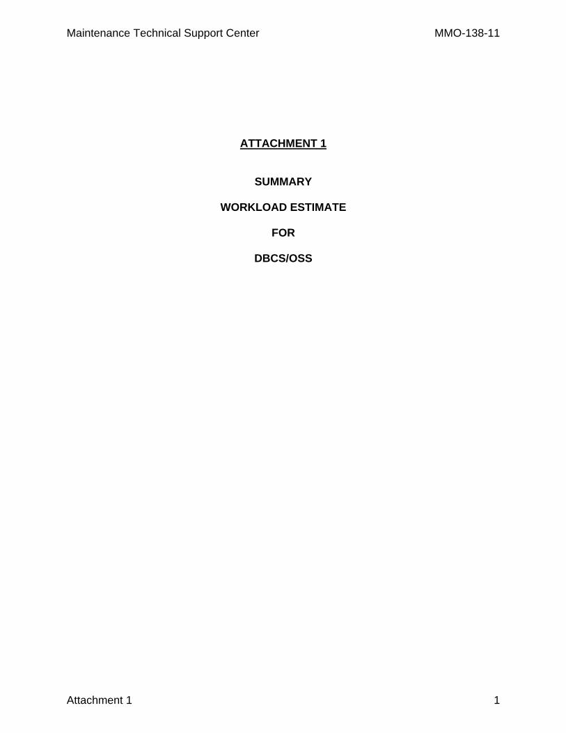
Power Off Tasks Threshold -> 3K 1.1M 1.1M 4.4M 14.3M Item # -> 6 9 10 11 21
110 9 35 37 139 21 126 1 5 3 10 3 142 2 10 6 20 6 158 3 15 9 30 9 174 4 20 12 40 12 190 5 25 15 50 15 206 6 30 18 60 18 222 7 35 21 70 21 238 8 40 24 80 24 254 9 45 27 90 27 270 10 50 30 100 30 286 11 55 33 110 33
# Stackers
302 12 60 36 120 36
Minutes
Power On Tasks
Threshold -> 1 Month 1K 1.1M 14.3M 14.3M Item # -> 25 22 31 26 32
110 18 5 7 219 14 126 2 1 1 10 2 142 4 1 2 20 2 158 6 1 3 30 3 174 8 1 4 40 3 190 10 2 5 52 4 206 12 2 6 62 4 222 14 2 7 72 5 238 16 2 8 82 5 254 18 3 9 90 6 270 20 3 10 100 6 286 22 3 11 110 7
# Stackers
302 24 3 12 120 7
Minutes

MMO-138-11 Maintenance Technical Support Center
6 Attachment 1
THIS PAGE BLANK
Maintenance Technical Support Center MMO-138-11
Attachment 2 1
ATTACHMENT 2
MASTER CHECKLIST
03-DBCS-CI-001-M
POWER OFF AND POWER ON TASKS
Time Total: See roll-ups in Attachment 1.
MMO-138-11 Maintenance Technical Support Center
U.S. Postal Service IDENTIFICATION
Maintenance Checklist WORK CODE
EQUIPMENT ACRONYM
CLASS CODE
NUMBER TYPE
0 3 D B C S C I 0 0 1 M Equipment Nomenclature
Delivery Bar Code Sorter Equipment Model
DBCS/OSS Bulletin Filename
MM10112AK Occurrence
ECBM
Thresholds
Part or Component
Item No
Task Statement and Instruction (Comply with all current safety precautions)
Est. Time Req (min)
Min. Skill Lev Run
Hours
Pieces Fed
(000)
Freq.
2 Attachment 2
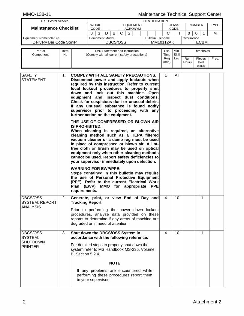
SAFETY STATEMENT
1. COMPLY WITH ALL SAFETY PRECAUTIONS. Disconnect power and apply lockouts when required by this instruction. Refer to current local lockout procedures to properly shutdown and lock out this machine. Open equipment and inspect dust conditions. Check for suspicious dust or unusual debris. If any unusual substance is found notify supervisor prior to proceeding with any further action on the equipment.
THE USE OF COMPRESSED OR BLOWN AIR IS PROHIBITED. When cleaning is required, an alternative cleaning method such as a HEPA filtered vacuum cleaner or a damp rag must be used in place of compressed or blown air. A lint-free cloth or brush may be used on optical equipment only when other cleaning methods cannot be used. Report safety deficiencies to your supervisor immediately upon detection.
WARNING FOR EWP/PPE: Steps contained in this bulletin may require the use of Personal Protective Equipment (PPE). Refer to the current Electrical Work Plan (EWP) MMO for appropriate PPE requirements.
1 All
DBCS/OSS SYSTEM: REPORT ANALYSIS
2. Generate, print, or view End of Day and Tracking Report.
Prior to performing the power down lockout procedures, analyze data provided on these reports to determine if any areas of machine are degraded or in need of attention.
4 10 1
DBCS/OSS SYSTEM: SHUTDOWN PRINTER
3. Shut down the DBCS/OSS System in accordance with the following reference:
For detailed steps to properly shut down the system refer to MS Handbook MS-235, Volume B, Section 5.2.4.
NOTE
If any problems are encountered while performing these procedures report them to your supervisor.
4 10 1

Maintenance Technical Support Center MMO-138-11 U.S. Postal Service IDENTIFICATION
Maintenance Checklist WORK CODE
EQUIPMENT ACRONYM
CLASS CODE
NUMBER TYPE
0 3 D B C S C I 0 0 1 M Equipment Nomenclature
Delivery Bar Code Sorter Equipment Model
DBCS/OSS Bulletin Filename
MM10112AK Occurrence
ECBM
Thresholds
Part or Component
Item No
Task Statement and Instruction (Comply with all current safety precautions)
Est. Time Req (min)
Min. Skill Lev Run
Hours
Pieces Fed
(000)
Freq.
Attachment 2 3
DBCS/OSS SYSTEM: POWER DOWN
4. Power down and lock out power.
WARNING
Before performing the following steps you must don the appropriate PPE as required by the current Electrical Work Plan (EWP) MMO.
WARNING
Electrical power will always be present at the input of the disconnect device unless the circuit is disabled at the facility power distribution panel located at ___________________.
Power down the machine and lock out its electrical power as prescribed by the current local lockout instructions providing lockout/restore procedures.
1 ALL 1
DBCS/OSS SYSTEM: MAIL SEARCH
5. Mail search.
1. Remove all machine panels, except for diverter plate cover assemblies (Wimpy panels), stacker lower front panel assemblies,and Main Power Distribution panel.
2. Ensure each cover’s gas spring and retaining clip is able to hold cover in uppermost position. Report defective components to supervisor or perform work order.
3. Search all base plate areas and module interiors for mail.
4. Remove any mail pieces found.
5. Remove any large amounts of debris while doing this mail search to prevent clogging of the vacuum when doing vacuuming tasks.
6. Follow local procedures for returning mail to operations for processing.
9 7 3
MMO-138-11 Maintenance Technical Support Center
U.S. Postal Service IDENTIFICATION
Maintenance Checklist WORK CODE
EQUIPMENT ACRONYM
CLASS CODE
NUMBER TYPE
0 3 D B C S C I 0 0 1 M Equipment Nomenclature
Delivery Bar Code Sorter Equipment Model
DBCS/OSS Bulletin Filename
MM10112AK Occurrence
ECBM
Thresholds
Part or Component
Item No
Task Statement and Instruction (Comply with all current safety precautions)
Est. Time Req (min)
Min. Skill Lev Run
Hours
Pieces Fed
(000)
Freq.
4 Attachment 2
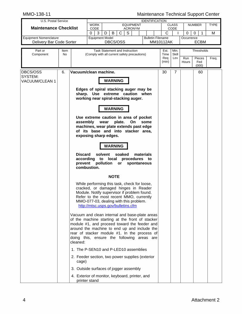
DBCS/OSS SYSTEM: VACUUM/CLEAN 1
6. Vacuum/clean machine.
WARNING
Edges of spiral stacking auger may be sharp. Use extreme caution when working near spiral-stacking auger.
WARNING
Use extreme caution in area of pocket assembly wear plate. On some machines, wear plate extends past edge of its base and into stacker area, exposing sharp edges.
WARNING
Discard solvent soaked materials according to local procedures to prevent pollution or spontaneous combustion.
NOTE
While performing this task, check for loose, cracked, or damaged hinges in Reader Module. Notify supervisor if problem found. Refer to the most recent MMO, currently MMO-077-03, dealing with this problem.
http://mtsc.usps.gov/bulletins.cfm Vacuum and clean internal and base-plate areas of the machine starting at the front of stacker module #1, and proceed toward the feeder and around the machine to end up and include the rear of stacker module #1. In the process of doing this, ensure the following areas are cleaned:
1. The P-SEN10 and P-LED10 assemblies
2. Feeder section, two power supplies (exterior cage)
3. Outside surfaces of jogger assembly
4. Exterior of monitor, keyboard, printer, and printer stand
30 7 60
Maintenance Technical Support Center MMO-138-11 U.S. Postal Service IDENTIFICATION
Maintenance Checklist WORK CODE
EQUIPMENT ACRONYM
CLASS CODE
NUMBER TYPE
0 3 D B C S C I 0 0 1 M Equipment Nomenclature
Delivery Bar Code Sorter Equipment Model
DBCS/OSS Bulletin Filename
MM10112AK Occurrence
ECBM
Thresholds
Part or Component
Item No
Task Statement and Instruction (Comply with all current safety precautions)
Est. Time Req (min)
Min. Skill Lev Run
Hours
Pieces Fed
(000)
Freq.
Attachment 2 5
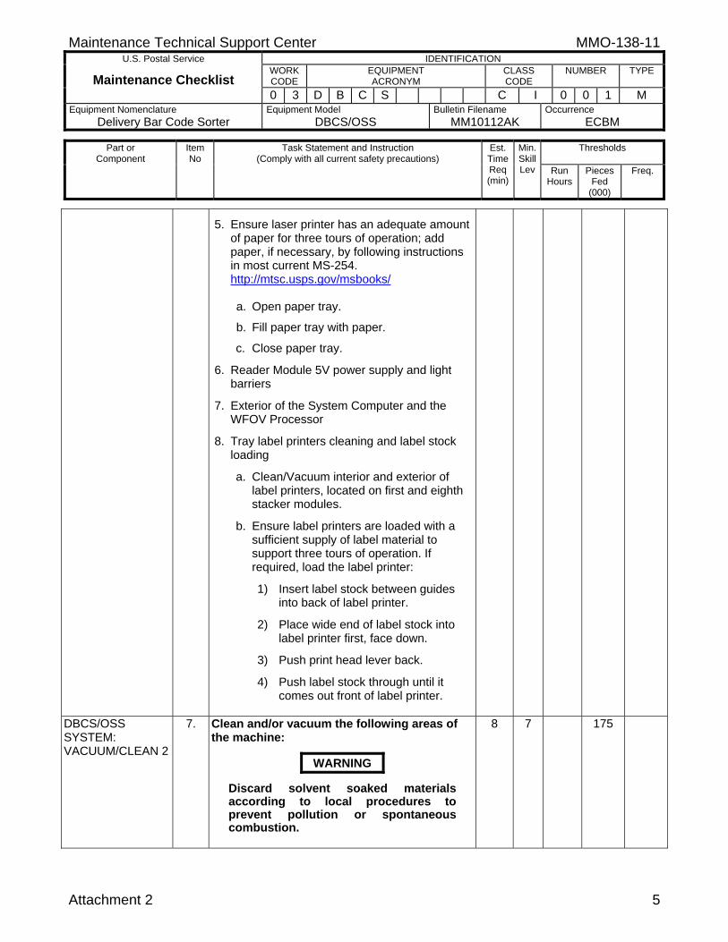
5. Ensure laser printer has an adequate amount of paper for three tours of operation; add paper, if necessary, by following instructions in most current MS-254. http://mtsc.usps.gov/msbooks/
a. Open paper tray.
b. Fill paper tray with paper.
c. Close paper tray.
6. Reader Module 5V power supply and light barriers
7. Exterior of the System Computer and the WFOV Processor
8. Tray label printers cleaning and label stock loading
a. Clean/Vacuum interior and exterior of label printers, located on first and eighth stacker modules.
b. Ensure label printers are loaded with a sufficient supply of label material to support three tours of operation. If required, load the label printer:
1) Insert label stock between guides into back of label printer.
2) Place wide end of label stock into label printer first, face down.
3) Push print head lever back.
4) Push label stock through until it comes out front of label printer.
DBCS/OSS SYSTEM: VACUUM/CLEAN 2
7. Clean and/or vacuum the following areas of the machine:
WARNING
Discard solvent soaked materials according to local procedures to prevent pollution or spontaneous combustion.
8 7 175

MMO-138-11 Maintenance Technical Support Center
U.S. Postal Service IDENTIFICATION
Maintenance Checklist WORK CODE
EQUIPMENT ACRONYM
CLASS CODE
NUMBER TYPE
0 3 D B C S C I 0 0 1 M Equipment Nomenclature
Delivery Bar Code Sorter Equipment Model
DBCS/OSS Bulletin Filename
MM10112AK Occurrence
ECBM
Thresholds
Part or Component
Item No
Task Statement and Instruction (Comply with all current safety precautions)
Est. Time Req (min)
Min. Skill Lev Run
Hours
Pieces Fed
(000)
Freq.
6 Attachment 2
1. Clean ICS-3 system electronic enclosure. Clean interior of ICS-3 electronic enclosure and electronic enclosure filters.
2. Clean ICS-3 system read head as follows:
a. Clean ICS-3 read head. Recommended cleaner is Riptide, NSN 6850-01-394-0164.
b. Clean read head reflector. Recommended cleaner is Riptide.
3. Clean WFOV assembly.
WARNING
Use extreme caution when working around the WFOV aperture. The edges of the aperture may become extremely sharp during use of the DBCS.
a. Following safety precautions, remove the
Aperture/Illumination assembly. Loosen the thumbscrew on top and pull straight up to remove. Check the aperture plates and sapphire glass for foreign objects.
b. Remove dust buildup on exterior of camera sapphire glass using dry cotton swabs. If adhesive buildup appears on the sapphire glass, use a swab or soft cloth wetted with an acceptable site approved cleaner.
c. If dust is found inside Aperture/ Illumination assembly, refer to most current documentation, currently MS-212, Appendix A for detailed cleaning instructions.
d. Replace Aperture/Illumination assembly. Slide assembly straight down on front of camera head assembly and tighten thumbscrew.
DBCS/OSS SYSTEM: VACUUM/CLEAN 3 STACKERS
8. Clean stacker modules 2 through to the end module by vacuuming; remove dust and debris as follows:
35 7 1100

Maintenance Technical Support Center MMO-138-11 U.S. Postal Service IDENTIFICATION
Maintenance Checklist WORK CODE
EQUIPMENT ACRONYM
CLASS CODE
NUMBER TYPE
0 3 D B C S C I 0 0 1 M Equipment Nomenclature
Delivery Bar Code Sorter Equipment Model
DBCS/OSS Bulletin Filename
MM10112AK Occurrence
ECBM
Thresholds
Part or Component
Item No
Task Statement and Instruction (Comply with all current safety precautions)
Est. Time Req (min)
Min. Skill Lev Run
Hours
Pieces Fed
(000)
Freq.
Attachment 2 7
WARNING
Edges of spiral stacking auger may be sharp. Use extreme caution when working near spiral stacking auger.
WARNING
Use extreme caution in area of pocket assembly wear plate. On some machines, wear plate extends past edge of its base and into stacker area, exposing sharp edges.
WARNING
Discard solvent soaked materials according to local procedures to prevent pollution or spontaneous combustion.
1. Clean stacker modules #2 through the end of the machine, transport area, interior, and pocket assemblies, including light barriers. This does not include the Wimpy Panels.
2. Ensure light barriers are clean.
DBCS/OSS SYSTEM: BELTS, ROLLERS AND HARDWARE
9. Check belts and rollers.
WARNING
Discard solvent soaked materials according to local procedures to prevent pollution or spontaneous combustion.
Starting at the front of stacker module #1, proceed toward feeder and around the machine to end up and include the rear of stacker module #1. Then proceed down the back of the stacker modules and around the front of the stacker modules to end at the front of stacker #2.
1. Check all belts (drive and letter transport) for indications of wear. Replace worn, deformed, split, or torn belts.
2. Check for broken or burred gate flags.
37 9 1100

MMO-138-11 Maintenance Technical Support Center
U.S. Postal Service IDENTIFICATION
Maintenance Checklist WORK CODE
EQUIPMENT ACRONYM
CLASS CODE
NUMBER TYPE
0 3 D B C S C I 0 0 1 M Equipment Nomenclature
Delivery Bar Code Sorter Equipment Model
DBCS/OSS Bulletin Filename
MM10112AK Occurrence
ECBM
Thresholds
Part or Component
Item No
Task Statement and Instruction (Comply with all current safety precautions)
Est. Time Req (min)
Min. Skill Lev Run
Hours
Pieces Fed
(000)
Freq.
8 Attachment 2
3. Write work orders as needed for replacement of belts and/or gates.
4. Check all rollers/sprockets (drive and idler) for proper adjustment and indications of wear and/or dirt buildup. Clean or replace rollers as necessary.
5. In the Reader Module, clean the motor power unit filter.
6. Write work orders as needed for adjustments, cleaning, and/or replacement of rollers.
DBCS/OSS SYSTEM: VACUUM/CLEAN 4
10. Perform the following steps to ensure all areas of the machine not covered in previous tasks are properly vacuumed and cleaned.
WARNING
Edges of spiral stacking auger may be sharp. Use extreme caution when working near spiral stacking auger.
WARNING
Use extreme caution in area of pocket assembly wear plate. On some machines, wear plate extends past edge of its base and into stacker area, exposing sharp edges.
WARNING
Discard solvent soaked materials according to local procedures to prevent pollution or spontaneous combustion.
NOTE
While performing following tasks, do a visual check of wiring harnesses, cabling, and connectors for wear, loose connections, etc., and if any problems are found, write a work order to do corrective maintenance. Open any additional doors including the plate cover assemblies (Wimpy Panels) in order to perform the following cleaning steps.
139 7 4400
Maintenance Technical Support Center MMO-138-11 U.S. Postal Service IDENTIFICATION
Maintenance Checklist WORK CODE
EQUIPMENT ACRONYM
CLASS CODE
NUMBER TYPE
0 3 D B C S C I 0 0 1 M Equipment Nomenclature
Delivery Bar Code Sorter Equipment Model
DBCS/OSS Bulletin Filename
MM10112AK Occurrence
ECBM
Thresholds
Part or Component
Item No
Task Statement and Instruction (Comply with all current safety precautions)
Est. Time Req (min)
Min. Skill Lev Run
Hours
Pieces Fed
(000)
Freq.
Attachment 2 9
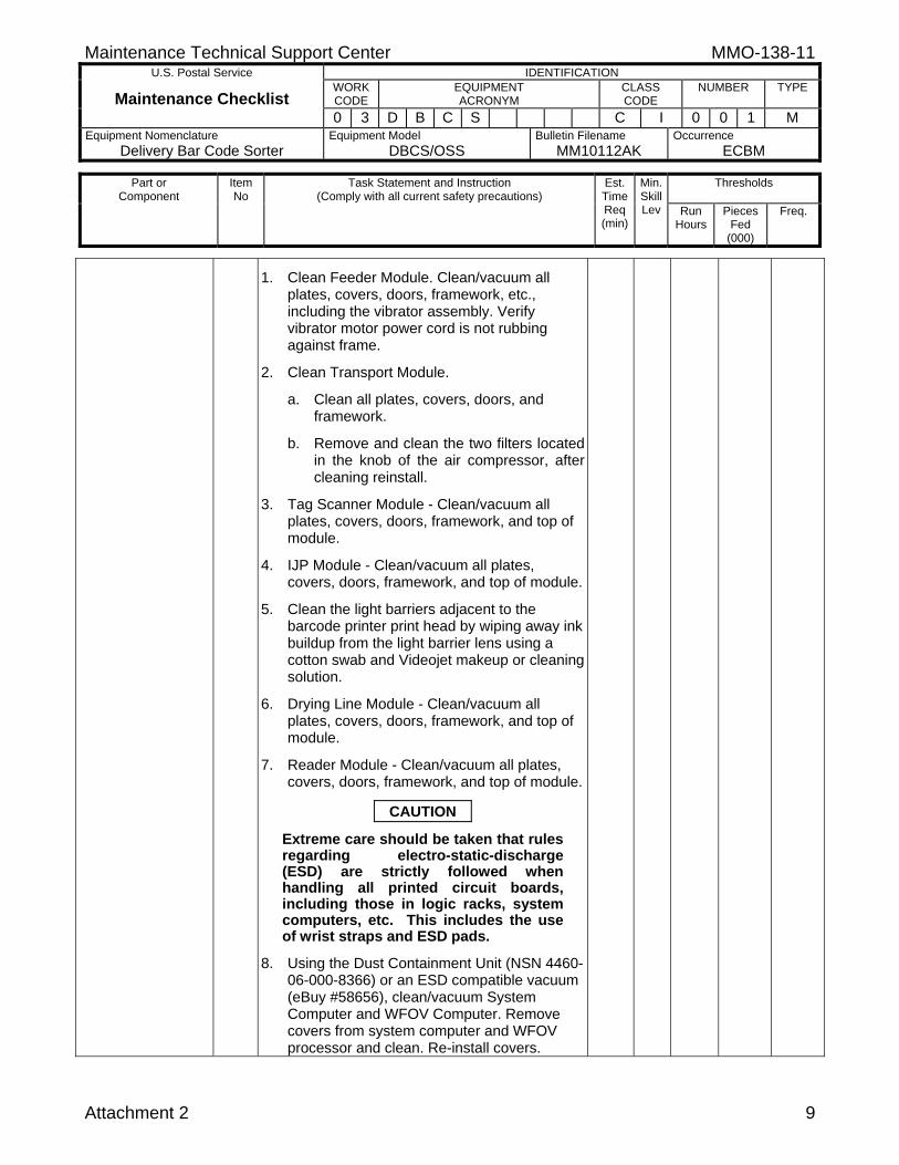
1. Clean Feeder Module. Clean/vacuum all plates, covers, doors, framework, etc., including the vibrator assembly. Verify vibrator motor power cord is not rubbing against frame.
2. Clean Transport Module.
a. Clean all plates, covers, doors, and framework.
b. Remove and clean the two filters located in the knob of the air compressor, after cleaning reinstall.
3. Tag Scanner Module - Clean/vacuum all plates, covers, doors, framework, and top of module.
4. IJP Module - Clean/vacuum all plates, covers, doors, framework, and top of module.
5. Clean the light barriers adjacent to the barcode printer print head by wiping away ink buildup from the light barrier lens using a cotton swab and Videojet makeup or cleaning solution.
6. Drying Line Module - Clean/vacuum all plates, covers, doors, framework, and top of module.
7. Reader Module - Clean/vacuum all plates, covers, doors, framework, and top of module.
CAUTION
Extreme care should be taken that rules regarding electro-static-discharge (ESD) are strictly followed when handling all printed circuit boards, including those in logic racks, system computers, etc. This includes the use of wrist straps and ESD pads.
8. Using the Dust Containment Unit (NSN 4460-06-000-8366) or an ESD compatible vacuum (eBuy #58656), clean/vacuum System Computer and WFOV Computer. Remove covers from system computer and WFOV processor and clean. Re-install covers.
MMO-138-11 Maintenance Technical Support Center
U.S. Postal Service IDENTIFICATION
Maintenance Checklist WORK CODE
EQUIPMENT ACRONYM
CLASS CODE
NUMBER TYPE
0 3 D B C S C I 0 0 1 M Equipment Nomenclature
Delivery Bar Code Sorter Equipment Model
DBCS/OSS Bulletin Filename
MM10112AK Occurrence
ECBM
Thresholds
Part or Component
Item No
Task Statement and Instruction (Comply with all current safety precautions)
Est. Time Req (min)
Min. Skill Lev Run
Hours
Pieces Fed
(000)
Freq.
10 Attachment 2
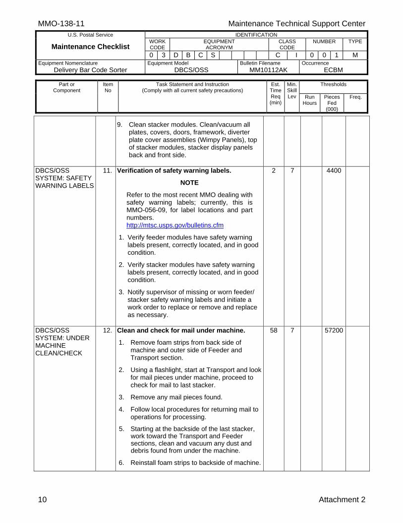
9. Clean stacker modules. Clean/vacuum all plates, covers, doors, framework, diverter plate cover assemblies (Wimpy Panels), top of stacker modules, stacker display panels back and front side.
DBCS/OSS SYSTEM: SAFETY WARNING LABELS
11. Verification of safety warning labels.
NOTE
Refer to the most recent MMO dealing with safety warning labels; currently, this is MMO-056-09, for label locations and part numbers. http://mtsc.usps.gov/bulletins.cfm
1. Verify feeder modules have safety warning labels present, correctly located, and in good condition.
2. Verify stacker modules have safety warning labels present, correctly located, and in good condition.
3. Notify supervisor of missing or worn feeder/ stacker safety warning labels and initiate a work order to replace or remove and replace as necessary.
2 7 4400
DBCS/OSS SYSTEM: UNDER MACHINE CLEAN/CHECK
12. Clean and check for mail under machine.
1. Remove foam strips from back side of machine and outer side of Feeder and Transport section.
2. Using a flashlight, start at Transport and look for mail pieces under machine, proceed to check for mail to last stacker.
3. Remove any mail pieces found.
4. Follow local procedures for returning mail to operations for processing.
5. Starting at the backside of the last stacker, work toward the Transport and Feeder sections, clean and vacuum any dust and debris found from under the machine.
6. Reinstall foam strips to backside of machine.
58 7 57200
Maintenance Technical Support Center MMO-138-11 U.S. Postal Service IDENTIFICATION
Maintenance Checklist WORK CODE
EQUIPMENT ACRONYM
CLASS CODE
NUMBER TYPE
0 3 D B C S C I 0 0 1 M Equipment Nomenclature
Delivery Bar Code Sorter Equipment Model
DBCS/OSS Bulletin Filename
MM10112AK Occurrence
ECBM
Thresholds
Part or Component
Item No
Task Statement and Instruction (Comply with all current safety precautions)
Est. Time Req (min)
Min. Skill Lev Run
Hours
Pieces Fed
(000)
Freq.
Attachment 2 11
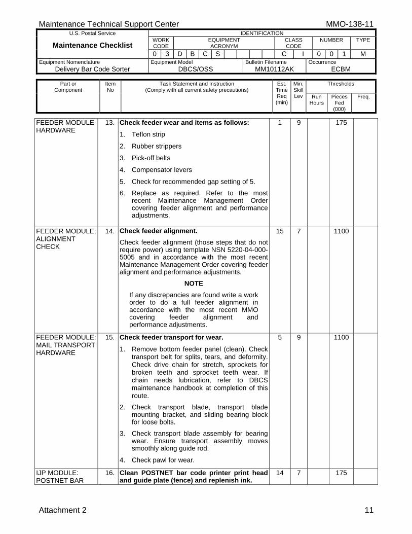
FEEDER MODULE HARDWARE
13. Check feeder wear and items as follows:
1. Teflon strip
2. Rubber strippers
3. Pick-off belts
4. Compensator levers
5. Check for recommended gap setting of 5.
6. Replace as required. Refer to the most recent Maintenance Management Order covering feeder alignment and performance adjustments.
1 9 175
FEEDER MODULE: ALIGNMENT CHECK
14. Check feeder alignment. Check feeder alignment (those steps that do not require power) using template NSN 5220-04-000-5005 and in accordance with the most recent Maintenance Management Order covering feeder alignment and performance adjustments.
NOTE If any discrepancies are found write a work order to do a full feeder alignment in accordance with the most recent MMO covering feeder alignment and performance adjustments.
15 7 1100
FEEDER MODULE: MAIL TRANSPORT HARDWARE
15. Check feeder transport for wear.
1. Remove bottom feeder panel (clean). Check transport belt for splits, tears, and deformity. Check drive chain for stretch, sprockets for broken teeth and sprocket teeth wear. If chain needs lubrication, refer to DBCS maintenance handbook at completion of this route.
2. Check transport blade, transport blade mounting bracket, and sliding bearing block for loose bolts.
3. Check transport blade assembly for bearing wear. Ensure transport assembly moves smoothly along guide rod.
4. Check pawl for wear.
5 9 1100
IJP MODULE: POSTNET BAR
16. Clean POSTNET bar code printer print head and guide plate (fence) and replenish ink.
14 7 175
MMO-138-11 Maintenance Technical Support Center
U.S. Postal Service IDENTIFICATION
Maintenance Checklist WORK CODE
EQUIPMENT ACRONYM
CLASS CODE
NUMBER TYPE
0 3 D B C S C I 0 0 1 M Equipment Nomenclature
Delivery Bar Code Sorter Equipment Model
DBCS/OSS Bulletin Filename
MM10112AK Occurrence
ECBM
Thresholds
Part or Component
Item No
Task Statement and Instruction (Comply with all current safety precautions)
Est. Time Req (min)
Min. Skill Lev Run
Hours
Pieces Fed
(000)
Freq.
12 Attachment 2
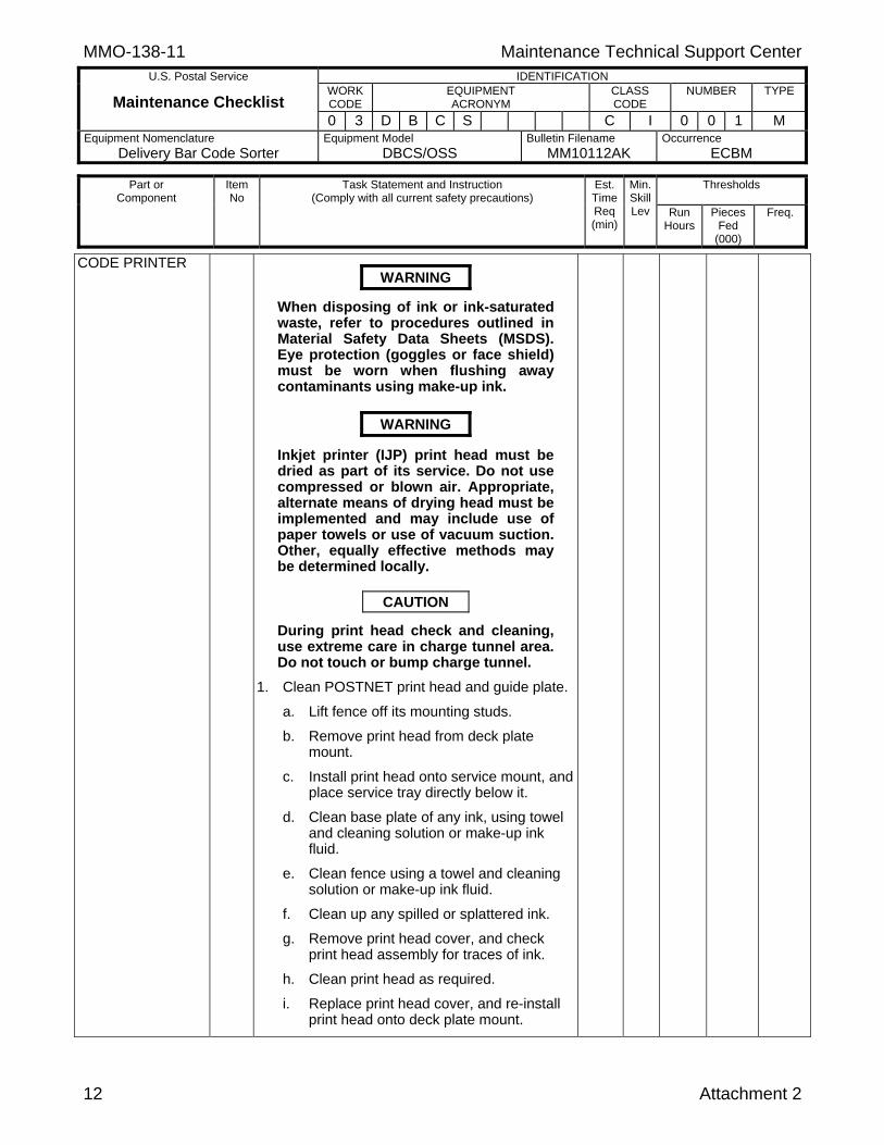
CODE PRINTER
WARNING
When disposing of ink or ink-saturated waste, refer to procedures outlined in Material Safety Data Sheets (MSDS). Eye protection (goggles or face shield) must be worn when flushing away contaminants using make-up ink.
WARNING
Inkjet printer (IJP) print head must be dried as part of its service. Do not use compressed or blown air. Appropriate, alternate means of drying head must be implemented and may include use of paper towels or use of vacuum suction. Other, equally effective methods may be determined locally.
CAUTION
During print head check and cleaning, use extreme care in charge tunnel area. Do not touch or bump charge tunnel.
1. Clean POSTNET print head and guide plate.
a. Lift fence off its mounting studs.
b. Remove print head from deck plate mount.
c. Install print head onto service mount, and place service tray directly below it.
d. Clean base plate of any ink, using towel and cleaning solution or make-up ink fluid.
e. Clean fence using a towel and cleaning solution or make-up ink fluid.
f. Clean up any spilled or splattered ink.
g. Remove print head cover, and check print head assembly for traces of ink.
h. Clean print head as required.
i. Replace print head cover, and re-install print head onto deck plate mount.
Maintenance Technical Support Center MMO-138-11 U.S. Postal Service IDENTIFICATION
Maintenance Checklist WORK CODE
EQUIPMENT ACRONYM
CLASS CODE
NUMBER TYPE
0 3 D B C S C I 0 0 1 M Equipment Nomenclature
Delivery Bar Code Sorter Equipment Model
DBCS/OSS Bulletin Filename
MM10112AK Occurrence
ECBM
Thresholds
Part or Component
Item No
Task Statement and Instruction (Comply with all current safety precautions)
Est. Time Req (min)
Min. Skill Lev Run
Hours
Pieces Fed
(000)
Freq.
Attachment 2 13
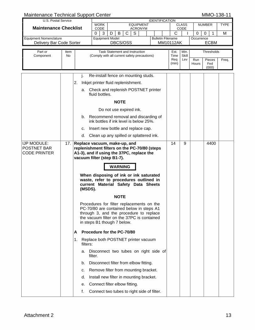
j. Re-install fence on mounting studs.
2. Inkjet printer fluid replenishment.
a. Check and replenish POSTNET printer fluid bottles.
NOTE
Do not use expired ink.
b. Recommend removal and discarding of ink bottles if ink level is below 25%.
c. Insert new bottle and replace cap.
d. Clean up any spilled or splattered ink.
IJP MODULE: POSTNET BAR CODE PRINTER
17. Replace vacuum, make-up, and replenishment filters on the PC-70/80 (steps A1-3), and if using the 37PC, replace the vacuum filter (step B1-7).
WARNING
When disposing of ink or ink saturated waste, refer to procedures outlined in current Material Safety Data Sheets (MSDS).
NOTE Procedures for filter replacements on the PC-70/80 are contained below in steps A1 through 3, and the procedure to replace the vacuum filter on the 37PC is contained in steps B1 though 7 below.
A Procedure for the PC-70/80 1. Replace both POSTNET printer vacuum
filters: a. Disconnect two tubes on right side of
filter.
b. Disconnect filter from elbow fitting.
c. Remove filter from mounting bracket.
d. Install new filter in mounting bracket.
e. Connect filter elbow fitting.
f. Connect two tubes to right side of filter.
14 9 4400
MMO-138-11 Maintenance Technical Support Center
U.S. Postal Service IDENTIFICATION
Maintenance Checklist WORK CODE
EQUIPMENT ACRONYM
CLASS CODE
NUMBER TYPE
0 3 D B C S C I 0 0 1 M Equipment Nomenclature
Delivery Bar Code Sorter Equipment Model
DBCS/OSS Bulletin Filename
MM10112AK Occurrence
ECBM
Thresholds
Part or Component
Item No
Task Statement and Instruction (Comply with all current safety precautions)
Est. Time Req (min)
Min. Skill Lev Run
Hours
Pieces Fed
(000)
Freq.
14 Attachment 2
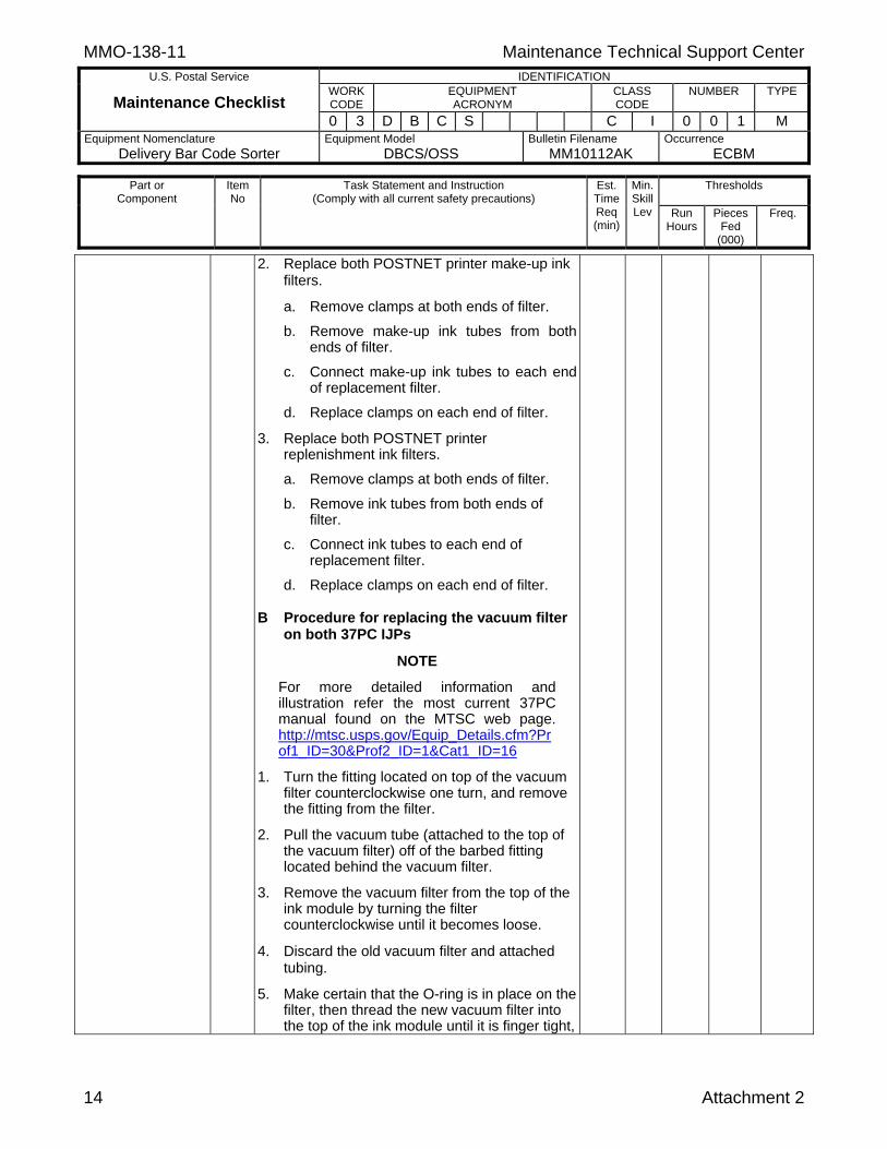
2. Replace both POSTNET printer make-up ink filters.
a. Remove clamps at both ends of filter.
b. Remove make-up ink tubes from both ends of filter.
c. Connect make-up ink tubes to each end of replacement filter.
d. Replace clamps on each end of filter.
3. Replace both POSTNET printer replenishment ink filters.
a. Remove clamps at both ends of filter.
b. Remove ink tubes from both ends of filter.
c. Connect ink tubes to each end of replacement filter.
d. Replace clamps on each end of filter.
B Procedure for replacing the vacuum filter on both 37PC IJPs
NOTE
For more detailed information and illustration refer the most current 37PC manual found on the MTSC web page. http://mtsc.usps.gov/Equip_Details.cfm?Prof1_ID=30&Prof2_ID=1&Cat1_ID=16
1. Turn the fitting located on top of the vacuum
filter counterclockwise one turn, and remove the fitting from the filter.
2. Pull the vacuum tube (attached to the top of the vacuum filter) off of the barbed fitting located behind the vacuum filter.
3. Remove the vacuum filter from the top of the ink module by turning the filter counterclockwise until it becomes loose.
4. Discard the old vacuum filter and attached tubing.
5. Make certain that the O-ring is in place on the filter, then thread the new vacuum filter into the top of the ink module until it is finger tight,
Maintenance Technical Support Center MMO-138-11 U.S. Postal Service IDENTIFICATION
Maintenance Checklist WORK CODE
EQUIPMENT ACRONYM
CLASS CODE
NUMBER TYPE
0 3 D B C S C I 0 0 1 M Equipment Nomenclature
Delivery Bar Code Sorter Equipment Model
DBCS/OSS Bulletin Filename
MM10112AK Occurrence
ECBM
Thresholds
Part or Component
Item No
Task Statement and Instruction (Comply with all current safety precautions)
Est. Time Req (min)
Min. Skill Lev Run
Hours
Pieces Fed
(000)
Freq.
Attachment 2 15
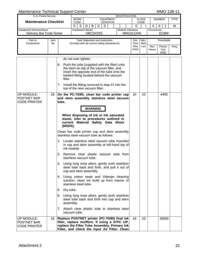
do not over tighten.
6. Push the tube (supplied with the filter) onto the stem on top of the vacuum filter, and insert the opposite end of the tube onto the barbed fitting located behind the vacuum filter.
7. Install the fitting removed in step #1 into the top of the new vacuum filter.
IJP MODULE: POSTNET BAR CODE PRINTER
18. On the PC-70/80, clean bar code printer cap and stem assembly stainless steel vacuum tube.
WARNING
When disposing of ink or ink saturated waste, refer to procedures outlined in current Material Safety Data Sheet (MSDS).
Clean bar code printer cap and stem assembly stainless steel vacuum tube as follows:
1. Locate stainless steel vacuum tube mounted in cap and stem assembly at left-hand top of ink module.
2. Remove clear plastic vacuum tube from stainless vacuum tube.
3. Using long nose pliers, gently work stainless steel tube back and forth, and pull it out of cap and stem assembly.
4. Using cotton swab and Videojet cleaning solution, clean ink build up from interior of stainless steel tube.
5. Dry tube.
6. Using long nose pliers, gently work stainless steel tube back and forth into cap and stem assembly.
7. Attach clear plastic tube to stainless steel vacuum tube.
10 10 4400
IJP MODULE: POSTNET BAR CODE PRINTER
19. Replace POSTNET printer (PC-70/80) final ink filter, replace mufflers. If using a 37PC IJP,replace the Filter Tube Assembly, Primary Ink Filter, and check the Input Air Filter. Clean
43 10 28600

MMO-138-11 Maintenance Technical Support Center
U.S. Postal Service IDENTIFICATION
Maintenance Checklist WORK CODE
EQUIPMENT ACRONYM
CLASS CODE
NUMBER TYPE
0 3 D B C S C I 0 0 1 M Equipment Nomenclature
Delivery Bar Code Sorter Equipment Model
DBCS/OSS Bulletin Filename
MM10112AK Occurrence
ECBM
Thresholds
Part or Component
Item No
Task Statement and Instruction (Comply with all current safety precautions)
Est. Time Req (min)
Min. Skill Lev Run
Hours
Pieces Fed
(000)
Freq.
16 Attachment 2
POSTNET Printer cabinets on all models PC-70/80/37.
WARNING
When disposing of ink or ink saturated waste, refer to procedures outlined in current Material Safety Data Sheets (MSDS).
A Procedures for the PC-70/80:
1. Replace trail and lead printer final ink filter at top of ink cylinder as follows:
a. Open doors on the POSTNET printer cabinet.
b. Place absorbent towels in area beneath ink module.
c. Remove ink line and filter from ink cylinder.
d. Install new filter.
e. Secure snugly, but do not over-tighten. Reattach ink line.
f. Close doors on the POSTNET printer cabinet.
g. Replace Lead printer final ink filter at top of ink cylinder by repeating steps a through f above, but for the Lead printer.
2. Clean POSTNET printer cabinets (lead and trail):
a. Open doors on both POSTNET printer cabinets.
b. Vacuum clean electronics side.
c. Clean ink side using lint free rags and appropriate solvent.
d. Close doors on both POSTNET Printer cabinets.
3. Replace inkjet printer muffler (lead and trail)as follows:
a. Remove muffler from bottom of IJP

Maintenance Technical Support Center MMO-138-11 U.S. Postal Service IDENTIFICATION
Maintenance Checklist WORK CODE
EQUIPMENT ACRONYM
CLASS CODE
NUMBER TYPE
0 3 D B C S C I 0 0 1 M Equipment Nomenclature
Delivery Bar Code Sorter Equipment Model
DBCS/OSS Bulletin Filename
MM10112AK Occurrence
ECBM
Thresholds
Part or Component
Item No
Task Statement and Instruction (Comply with all current safety precautions)
Est. Time Req (min)
Min. Skill Lev Run
Hours
Pieces Fed
(000)
Freq.
Attachment 2 17
cabinet.
b. Install new muffler.
4. Close printer doors.
B Procedures for the 37PC printers:
NOTE
For more detailed information and illustration refer to the most current MS Manual found on the MTSC web page. http://mtsc.usps.gov/Equip_Details.cfm?Prof1_ID=30&Prof2_ID=1&Cat1_ID=16
1. Replace primary ink filter (lead and trail).
a. Place absorbent towels below the ink module to catch any ink that may spill when removing the primary ink filter.
b. Remove the fitting from the bottom of the primary ink filter by turning with a 7/16inch wrench.
c. Unscrew the primary ink filter from the bottom of the ink module.
d. Wipe excess ink from the bottom of the ink module mounting hole.
e. Discard the old primary ink filter.
f. Install the new primary ink filter into the bottom of the ink module until finger tight. Do not over tighten. Hand tighten only.
g. Install the fitting into the bottom of the primary ink filter.
2. Complete the following steps to check and/or replace the input air filter:
a. Use a wrench to loosen the black nut at the top of the elbow fitting.
b. Use a dull, pointed instrument to pull the input air filter out of the bottom of the air manifold.
c. Check the input air filter for dirt and
MMO-138-11 Maintenance Technical Support Center
U.S. Postal Service IDENTIFICATION
Maintenance Checklist WORK CODE
EQUIPMENT ACRONYM
CLASS CODE
NUMBER TYPE
0 3 D B C S C I 0 0 1 M Equipment Nomenclature
Delivery Bar Code Sorter Equipment Model
DBCS/OSS Bulletin Filename
MM10112AK Occurrence
ECBM
Thresholds
Part or Component
Item No
Task Statement and Instruction (Comply with all current safety precautions)
Est. Time Req (min)
Min. Skill Lev Run
Hours
Pieces Fed
(000)
Freq.
18 Attachment 2
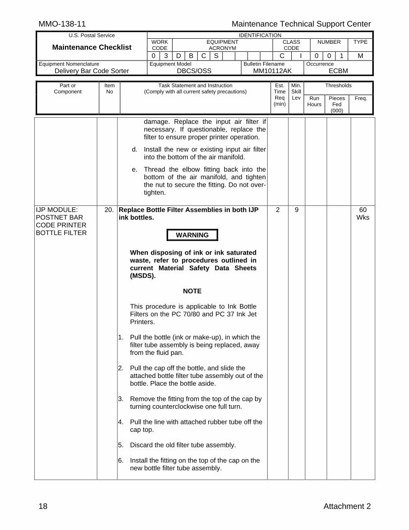
damage. Replace the input air filter if necessary. If questionable, replace the filter to ensure proper printer operation.
d. Install the new or existing input air filter into the bottom of the air manifold.
e. Thread the elbow fitting back into the bottom of the air manifold, and tighten the nut to secure the fitting. Do not over-tighten.
IJP MODULE: POSTNET BAR CODE PRINTER BOTTLE FILTER
20. Replace Bottle Filter Assemblies in both IJP ink bottles.
WARNING
When disposing of ink or ink saturated waste, refer to procedures outlined in current Material Safety Data Sheets (MSDS).
NOTE
This procedure is applicable to Ink Bottle Filters on the PC 70/80 and PC 37 Ink Jet Printers.
1. Pull the bottle (ink or make-up), in which the
filter tube assembly is being replaced, away from the fluid pan.
2. Pull the cap off the bottle, and slide the
attached bottle filter tube assembly out of the bottle. Place the bottle aside.
3. Remove the fitting from the top of the cap by
turning counterclockwise one full turn. 4. Pull the line with attached rubber tube off the
cap top. 5. Discard the old filter tube assembly. 6. Install the fitting on the top of the cap on the
new bottle filter tube assembly.
2 9 60 Wks
Maintenance Technical Support Center MMO-138-11 U.S. Postal Service IDENTIFICATION
Maintenance Checklist WORK CODE
EQUIPMENT ACRONYM
CLASS CODE
NUMBER TYPE
0 3 D B C S C I 0 0 1 M Equipment Nomenclature
Delivery Bar Code Sorter Equipment Model
DBCS/OSS Bulletin Filename
MM10112AK Occurrence
ECBM
Thresholds
Part or Component
Item No
Task Statement and Instruction (Comply with all current safety precautions)
Est. Time Req (min)
Min. Skill Lev Run
Hours
Pieces Fed
(000)
Freq.
Attachment 2 19
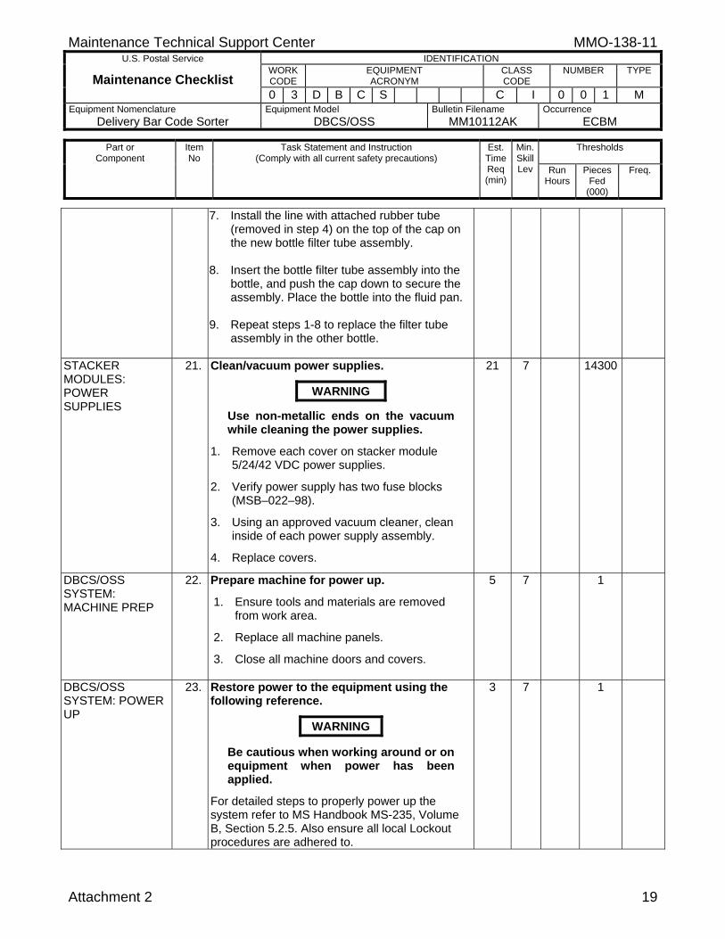
7. Install the line with attached rubber tube (removed in step 4) on the top of the cap on the new bottle filter tube assembly.
8. Insert the bottle filter tube assembly into the
bottle, and push the cap down to secure the assembly. Place the bottle into the fluid pan.
9. Repeat steps 1-8 to replace the filter tube
assembly in the other bottle.
STACKER MODULES: POWER SUPPLIES
21. Clean/vacuum power supplies.
WARNING
Use non-metallic ends on the vacuum while cleaning the power supplies.
1. Remove each cover on stacker module 5/24/42 VDC power supplies.
2. Verify power supply has two fuse blocks (MSB–022–98).
3. Using an approved vacuum cleaner, clean inside of each power supply assembly.
4. Replace covers.
21 7 14300
DBCS/OSS SYSTEM: MACHINE PREP
22. Prepare machine for power up.
1. Ensure tools and materials are removed from work area.
2. Replace all machine panels.
3. Close all machine doors and covers.
5 7 1
DBCS/OSS SYSTEM: POWER UP
23. Restore power to the equipment using the following reference.
WARNING
Be cautious when working around or on equipment when power has been applied.
For detailed steps to properly power up the system refer to MS Handbook MS-235, Volume B, Section 5.2.5. Also ensure all local Lockout procedures are adhered to.
3 7 1
MMO-138-11 Maintenance Technical Support Center
U.S. Postal Service IDENTIFICATION
Maintenance Checklist WORK CODE
EQUIPMENT ACRONYM
CLASS CODE
NUMBER TYPE
0 3 D B C S C I 0 0 1 M Equipment Nomenclature
Delivery Bar Code Sorter Equipment Model
DBCS/OSS Bulletin Filename
MM10112AK Occurrence
ECBM
Thresholds
Part or Component
Item No
Task Statement and Instruction (Comply with all current safety precautions)
Est. Time Req (min)
Min. Skill Lev Run
Hours
Pieces Fed
(000)
Freq.
20 Attachment 2
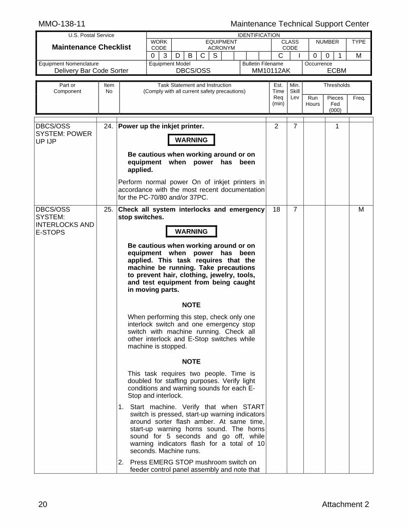
DBCS/OSS SYSTEM: POWER UP IJP
24. Power up the inkjet printer.
WARNING
Be cautious when working around or on equipment when power has been applied.
Perform normal power On of inkjet printers in accordance with the most recent documentation for the PC-70/80 and/or 37PC.
2 7 1
DBCS/OSS SYSTEM: INTERLOCKS AND E-STOPS
25. Check all system interlocks and emergency stop switches.
WARNING
Be cautious when working around or on equipment when power has been applied. This task requires that the machine be running. Take precautions to prevent hair, clothing, jewelry, tools, and test equipment from being caught in moving parts.
NOTE
When performing this step, check only one interlock switch and one emergency stop switch with machine running. Check all other interlock and E-Stop switches while machine is stopped.
NOTE
This task requires two people. Time is doubled for staffing purposes. Verify light conditions and warning sounds for each E-Stop and interlock.
1. Start machine. Verify that when START switch is pressed, start-up warning indicators around sorter flash amber. At same time,start-up warning horns sound. The horns sound for 5 seconds and go off, while warning indicators flash for a total of 10 seconds. Machine runs.
2. Press EMERG STOP mushroom switch on feeder control panel assembly and note that
18 7 M

Maintenance Technical Support Center MMO-138-11 U.S. Postal Service IDENTIFICATION
Maintenance Checklist WORK CODE
EQUIPMENT ACRONYM
CLASS CODE
NUMBER TYPE
0 3 D B C S C I 0 0 1 M Equipment Nomenclature
Delivery Bar Code Sorter Equipment Model
DBCS/OSS Bulletin Filename
MM10112AK Occurrence
ECBM
Thresholds
Part or Component
Item No
Task Statement and Instruction (Comply with all current safety precautions)
Est. Time Req (min)
Min. Skill Lev Run
Hours
Pieces Fed
(000)
Freq.
Attachment 2 21
following occurs:
a. Machine stops immediately.
b. Lamp lights in EMERG STOP switch.
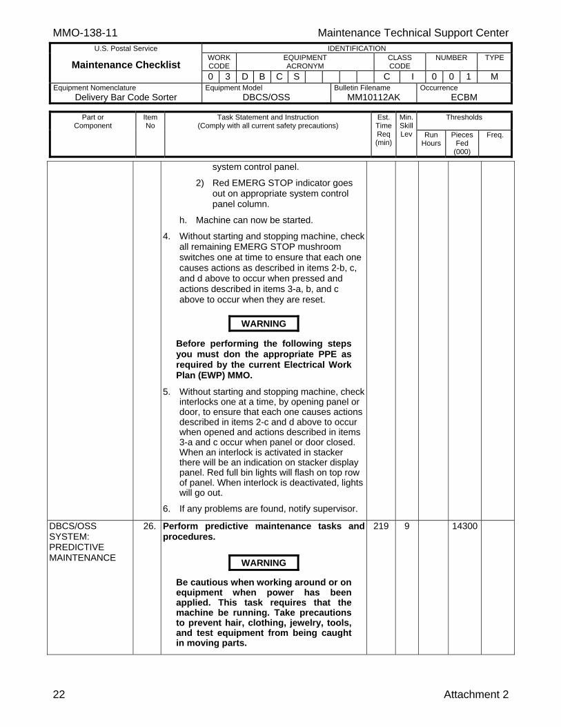
c. Red EMERG STOP indicator lights on appropriate system control panel column.
d. READY lamp goes out on system control panel.
e. Pressing Start pushbutton does not start machine.
3. Reset EMERG STOP mushroom switch and note that following occurs:
a. System READY lamp illuminates on system control panel.
b. Red EMERG STOP indicator goes out on appropriate system control panel column.
c. Lamp goes out in module control panel EMERG STOP switch.
d. Machine can now be started.
e. Start machine. Verify that when START switch is pressed, start-up warning indicators around sorter flash amber. At same time, start-up warning horns sound. The horns sound for 5 seconds and go off, while warning indicators flash for a total of 10 seconds. Machine runs.
f. Open Reader Module front panel door
and note that the following occurs:
1) Machine stops immediately.
2) Red EMERG STOP indicator lights on appropriate system control panel column.
3) READY lamp goes out on system control panel.
4) Pressing Start pushbutton does not start machine.
g. Close Reader Module front panel door and note that the following occurs:
1) System READY lamp illuminates on
MMO-138-11 Maintenance Technical Support Center
U.S. Postal Service IDENTIFICATION
Maintenance Checklist WORK CODE
EQUIPMENT ACRONYM
CLASS CODE
NUMBER TYPE
0 3 D B C S C I 0 0 1 M Equipment Nomenclature
Delivery Bar Code Sorter Equipment Model
DBCS/OSS Bulletin Filename
MM10112AK Occurrence
ECBM
Thresholds
Part or Component
Item No
Task Statement and Instruction (Comply with all current safety precautions)
Est. Time Req (min)
Min. Skill Lev Run
Hours
Pieces Fed
(000)
Freq.
22 Attachment 2
system control panel.
2) Red EMERG STOP indicator goes out on appropriate system control panel column.
h. Machine can now be started.
4. Without starting and stopping machine, check all remaining EMERG STOP mushroom switches one at time to ensure that each one causes actions as described in items 2-b, c, and d above to occur when pressed and actions described in items 3-a, b, and c above to occur when they are reset.
WARNING
Before performing the following steps you must don the appropriate PPE as required by the current Electrical Work Plan (EWP) MMO.
5. Without starting and stopping machine, check interlocks one at a time, by opening panel or door, to ensure that each one causes actions described in items 2-c and d above to occur when opened and actions described in items 3-a and c occur when panel or door closed. When an interlock is activated in stacker there will be an indication on stacker display panel. Red full bin lights will flash on top row of panel. When interlock is deactivated, lights will go out.
6. If any problems are found, notify supervisor.
DBCS/OSS SYSTEM: PREDICTIVE MAINTENANCE
26. Perform predictive maintenance tasks and procedures.
WARNING
Be cautious when working around or on equipment when power has been applied. This task requires that the machine be running. Take precautions to prevent hair, clothing, jewelry, tools, and test equipment from being caught in moving parts.
219 9 14300
Maintenance Technical Support Center MMO-138-11 U.S. Postal Service IDENTIFICATION
Maintenance Checklist WORK CODE
EQUIPMENT ACRONYM
CLASS CODE
NUMBER TYPE
0 3 D B C S C I 0 0 1 M Equipment Nomenclature
Delivery Bar Code Sorter Equipment Model
DBCS/OSS Bulletin Filename
MM10112AK Occurrence
ECBM
Thresholds
Part or Component
Item No
Task Statement and Instruction (Comply with all current safety precautions)
Est. Time Req (min)
Min. Skill Lev Run
Hours
Pieces Fed
(000)
Freq.
Attachment 2 23
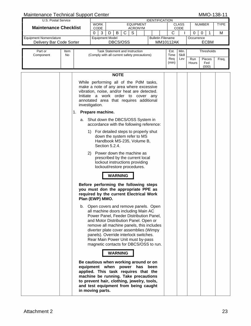
NOTE
While performing all of the PdM tasks, make a note of any area where excessive vibration, noise, and/or heat are detected. Initiate a work order to cover any annotated area that requires additional investigation.
1. Prepare machine.
a. Shut down the DBCS/OSS System in accordance with the following reference:
1) For detailed steps to properly shut down the system refer to MS Handbook MS-235, Volume B, Section 5.2.4.
2) Power down the machine as prescribed by the current local lockout instructions providing lockout/restore procedures.
WARNING
Before performing the following steps you must don the appropriate PPE as required by the current Electrical Work Plan (EWP) MMO.
b. Open covers and remove panels. Open all machine doors including Main AC Power Panel, Feeder Distribution Panel, and Motor Distribution Panel. Open or remove all machine panels, this includes diverter plate cover assemblies (Wimpy panels). Override interlock switches. Rear Main Power Unit must by-pass magnetic contacts for DBCS/OSS to run.
WARNING
Be cautious when working around or on equipment when power has been applied. This task requires that the machine be running. Take precautions to prevent hair, clothing, jewelry, tools, and test equipment from being caught in moving parts.
MMO-138-11 Maintenance Technical Support Center
U.S. Postal Service IDENTIFICATION
Maintenance Checklist WORK CODE
EQUIPMENT ACRONYM
CLASS CODE
NUMBER TYPE
0 3 D B C S C I 0 0 1 M Equipment Nomenclature
Delivery Bar Code Sorter Equipment Model
DBCS/OSS Bulletin Filename
MM10112AK Occurrence
ECBM
Thresholds
Part or Component
Item No
Task Statement and Instruction (Comply with all current safety precautions)
Est. Time Req (min)
Min. Skill Lev Run
Hours
Pieces Fed
(000)
Freq.
24 Attachment 2
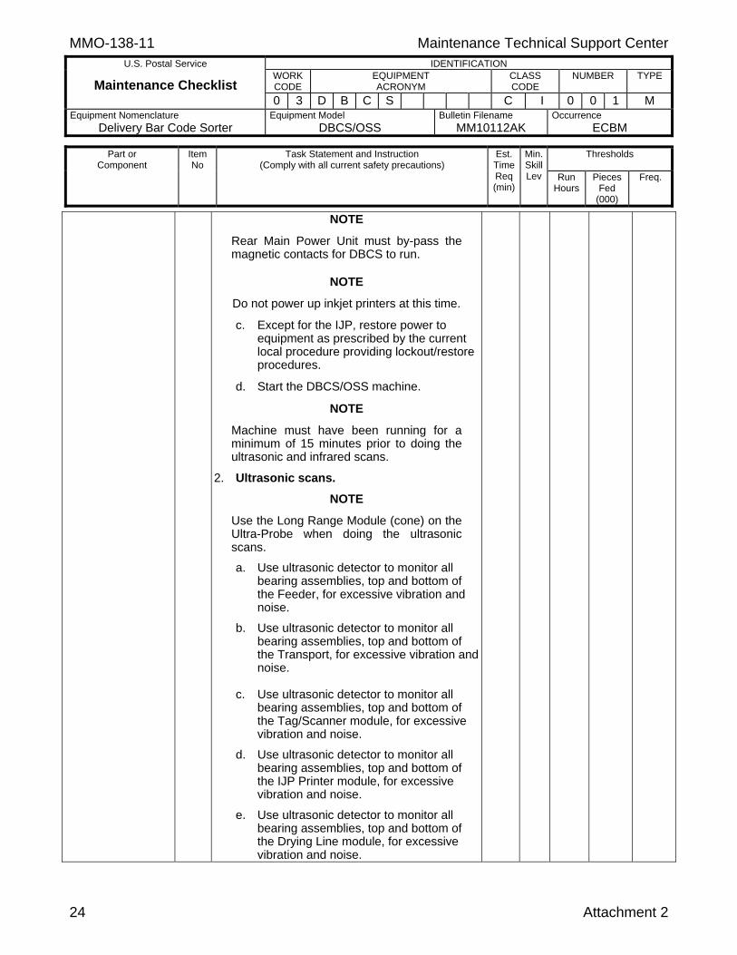
NOTE
Rear Main Power Unit must by-pass the magnetic contacts for DBCS to run.
NOTE
Do not power up inkjet printers at this time.
c. Except for the IJP, restore power to equipment as prescribed by the current local procedure providing lockout/restore procedures.
d. Start the DBCS/OSS machine.
NOTE
Machine must have been running for a minimum of 15 minutes prior to doing the ultrasonic and infrared scans.
2. Ultrasonic scans.
NOTE
Use the Long Range Module (cone) on the Ultra-Probe when doing the ultrasonic scans.
a. Use ultrasonic detector to monitor all bearing assemblies, top and bottom of the Feeder, for excessive vibration and noise.
b. Use ultrasonic detector to monitor all bearing assemblies, top and bottom of the Transport, for excessive vibration and noise.
c. Use ultrasonic detector to monitor all bearing assemblies, top and bottom of the Tag/Scanner module, for excessive vibration and noise.
d. Use ultrasonic detector to monitor all bearing assemblies, top and bottom of the IJP Printer module, for excessive vibration and noise.
e. Use ultrasonic detector to monitor all bearing assemblies, top and bottom of the Drying Line module, for excessive vibration and noise.

Maintenance Technical Support Center MMO-138-11 U.S. Postal Service IDENTIFICATION
Maintenance Checklist WORK CODE
EQUIPMENT ACRONYM
CLASS CODE
NUMBER TYPE
0 3 D B C S C I 0 0 1 M Equipment Nomenclature
Delivery Bar Code Sorter Equipment Model
DBCS/OSS Bulletin Filename
MM10112AK Occurrence
ECBM
Thresholds
Part or Component
Item No
Task Statement and Instruction (Comply with all current safety precautions)
Est. Time Req (min)
Min. Skill Lev Run
Hours
Pieces Fed
(000)
Freq.
Attachment 2 25
f. Use ultrasonic detector to monitor all bearing assemblies, top and bottom of the Reader module, for excessive vibration and noise.
g. Use ultrasonic detector to monitor all bearing assemblies, top and bottom of Motor Power Distribution, for excessive vibration and noise.
h. Use ultrasonic detector to monitor all bearing assemblies, top and bottom of Tiers 1-4 of the Stacker modules, for excessive vibration and noise.
3. Infrared scans.
a. Use non-contact infrared to scan Main Power Unit front and rear (magnetic interlock on panel), scan all terminal connections and connector plugs.
b. Use non-contact infrared to monitor all motors, terminal connections, and connector plugs in the Feeder for abnormal temperature.
c. Use non-contact infrared to monitor all terminal connections and connection plugs in the Feeder Distribution Panel for abnormal temperature.
d. Use non-contact infrared to monitor all motors, terminal connections, and connector plugs in the Transport for abnormal temperature.
e. Use non-contact infrared to monitor all terminal connections and connection plugs in the Tag/Scanner module for abnormal temperature.
f. Use non-contact infrared to monitor all terminal connections and connection plugs in the IJP module for abnormal temperature.
g. Use non-contact infrared to monitor all terminal connections and connection plugs in the Drying Line module for abnormal temperature.

MMO-138-11 Maintenance Technical Support Center
U.S. Postal Service IDENTIFICATION
Maintenance Checklist WORK CODE
EQUIPMENT ACRONYM
CLASS CODE
NUMBER TYPE
0 3 D B C S C I 0 0 1 M Equipment Nomenclature
Delivery Bar Code Sorter Equipment Model
DBCS/OSS Bulletin Filename
MM10112AK Occurrence
ECBM
Thresholds
Part or Component
Item No
Task Statement and Instruction (Comply with all current safety precautions)
Est. Time Req (min)
Min. Skill Lev Run
Hours
Pieces Fed
(000)
Freq.
26 Attachment 2
h. Use non-contact infrared to monitor to scan all terminal connections and connection plugs in the Drying Transport module for abnormal temperature.
i. Use non-contact infrared to monitor all terminal connections and connection plugs in Reader module for abnormal temperature.
j. Use non-contact infrared to monitor all terminal connections and connector plugs in the Motor Distribution Panel for abnormal temperature.
k. Use non-contact infrared to monitor all terminal connections and connector plugs in the Stacker Modules, Tiers 1-4 for abnormal temperature.
4. Restore equipment to ready status.
a. Shut down the DBCS/OSS System in accordance with the following references:
1) Refer to MS Handbook MS-235, Volume B, Section 5.2.4 for detailed steps to properly shut down the system.
2) Power down the machine as
prescribed by the current local lockout instructions providing lockout/restore procedures.
WARNING
Before performing the following steps you must don the appropriate PPE as required by the current Electrical Work Plan (EWP) MMO.
b. Replace all panels and doors. Ensure
tools and materials are removed from work area. Replace all machine panels. Close all machine doors and covers.

Maintenance Technical Support Center MMO-138-11 U.S. Postal Service IDENTIFICATION
Maintenance Checklist WORK CODE
EQUIPMENT ACRONYM
CLASS CODE
NUMBER TYPE
0 3 D B C S C I 0 0 1 M Equipment Nomenclature
Delivery Bar Code Sorter Equipment Model
DBCS/OSS Bulletin Filename
MM10112AK Occurrence
ECBM
Thresholds
Part or Component
Item No
Task Statement and Instruction (Comply with all current safety precautions)
Est. Time Req (min)
Min. Skill Lev Run
Hours
Pieces Fed
(000)
Freq.
Attachment 2 27
WARNING
Be cautious when working around or on equipment when power has been applied.
c. Restore power to equipment as prescribed by the current local procedure providing lockout/restore procedure.
d. Power on computer systems using current local computer restore procedures.
e. Perform normal power on of inkjet printers in accordance with the most recent documentation for the PC-70/80 and/or 37PC.
FEEDER MODULE: ALIGNMENT CHECK
27. Check feeder alignment.
WARNING
Be cautious when working around or on equipment when power has been applied.
Check feeder alignment (Power On steps) using template NSN 5220-04-000-5005 and in accordance with the most recent Maintenance Management Order covering feeder alignment and performance adjustments.
NOTE If any discrepancies are found, write a work order to do a full feeder alignment in accordance with the most recent MMO covering feeder alignment and performance adjustments.
15 7 1100
TAG SCANNER MODULE: ID TAG READER
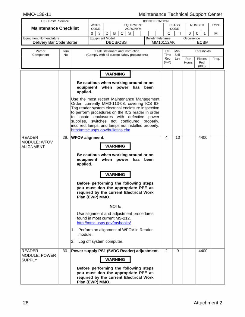
28. ID Tag Reader System electrical enclosure inspection.
WARNING
Before performing the following steps you must don the appropriate PPE as required by the current Electrical Work Plan (EWP) MMO.
10 10 4400
MMO-138-11 Maintenance Technical Support Center
U.S. Postal Service IDENTIFICATION
Maintenance Checklist WORK CODE
EQUIPMENT ACRONYM
CLASS CODE
NUMBER TYPE
0 3 D B C S C I 0 0 1 M Equipment Nomenclature
Delivery Bar Code Sorter Equipment Model
DBCS/OSS Bulletin Filename
MM10112AK Occurrence
ECBM
Thresholds
Part or Component
Item No
Task Statement and Instruction (Comply with all current safety precautions)
Est. Time Req (min)
Min. Skill Lev Run
Hours
Pieces Fed
(000)
Freq.
28 Attachment 2
WARNING
Be cautious when working around or on equipment when power has been applied.
Use the most recent Maintenance Management Order, currently MM0-113-08, covering ICS ID-Tag reader system electrical enclosure inspection to perform procedures on the ICS reader in order to locate enclosures with defective power supplies, switches not configured properly, incorrect lamps, and lamps not installed properly. http://mtsc.usps.gov/bulletins.cfm
READER MODULE: WFOV ALIGNMENT
29. WFOV alignment.
WARNING
Be cautious when working around or on equipment when power has been applied.
WARNING
Before performing the following steps you must don the appropriate PPE as required by the current Electrical Work Plan (EWP) MMO.
NOTE
Use alignment and adjustment procedures found in most current MS-212. http://mtsc.usps.gov/msbooks/
1. Perform an alignment of WFOV in Reader module.
2. Log off system computer.
4 10 4400
READER MODULE: POWER SUPPLY
30. Power supply PS1 (5VDC Reader) adjustment.
WARNING
Before performing the following steps you must don the appropriate PPE as required by the current Electrical Work Plan (EWP) MMO.
2 9 4400

Maintenance Technical Support Center MMO-138-11 U.S. Postal Service IDENTIFICATION
Maintenance Checklist WORK CODE
EQUIPMENT ACRONYM
CLASS CODE
NUMBER TYPE
0 3 D B C S C I 0 0 1 M Equipment Nomenclature
Delivery Bar Code Sorter Equipment Model
DBCS/OSS Bulletin Filename
MM10112AK Occurrence
ECBM
Thresholds
Part or Component
Item No
Task Statement and Instruction (Comply with all current safety precautions)
Est. Time Req (min)
Min. Skill Lev Run
Hours
Pieces Fed
(000)
Freq.
Attachment 2 29
WARNING
Be cautious when working around or on equipment when power has been applied.
1. Open Reader lower left door.
2. Place multimeter leads with clips on connectors J14 and J15 of Reader card cage backplane.
3. A reading of 5.1 VDC should be present, if not adjust, 5 VDC power supply potentiometer to obtain a reading of +5.0 VDC (+0.1/-0.0 VDC).
4. Close door.
STACKER MODULES: BIN SWITCH TEST
31. Stacker bin-full switch checks.
WARNING
Be cautious when working around or on equipment when power has been applied.
1. Pull each stacker blade to its 3/4 full position and note that its associated red indicator on stacker module display panel flashes and stacker module horn beeps. Note defective stacker switches.
2. Pull each stacker blade to its full position and note that its associated red indicator on stacker module display panel is illuminated and stacker module horn beeps. Note defective stacker switches.
3. Verify stacker blade rides smoothly on the guide rod.
4. Notify supervisor of defective stacker switches and/or blades and initiate a work order to repair or replace as necessary.
7 7 1100
MMO-138-11 Maintenance Technical Support Center
U.S. Postal Service IDENTIFICATION
Maintenance Checklist WORK CODE
EQUIPMENT ACRONYM
CLASS CODE
NUMBER TYPE
0 3 D B C S C I 0 0 1 M Equipment Nomenclature
Delivery Bar Code Sorter Equipment Model
DBCS/OSS Bulletin Filename
MM10112AK Occurrence
ECBM
Thresholds
Part or Component
Item No
Task Statement and Instruction (Comply with all current safety precautions)
Est. Time Req (min)
Min. Skill Lev Run
Hours
Pieces Fed
(000)
Freq.
30 Attachment 2
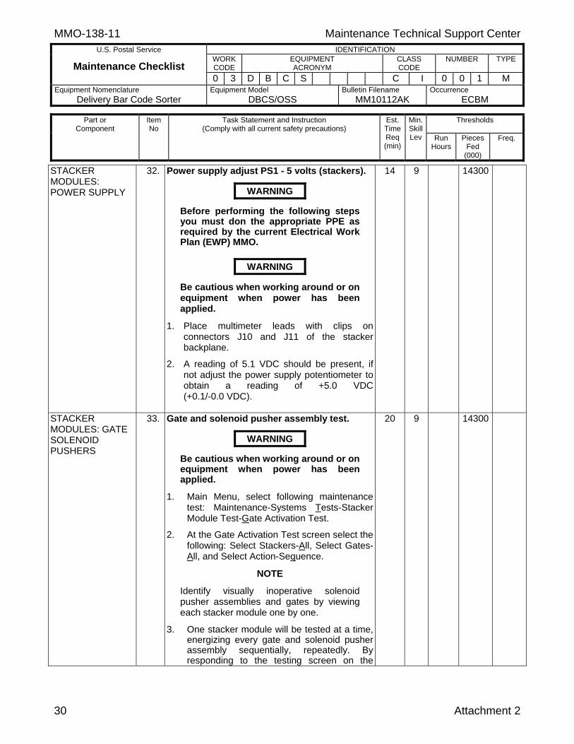
STACKER MODULES: POWER SUPPLY
32. Power supply adjust PS1 - 5 volts (stackers).
WARNING
Before performing the following steps you must don the appropriate PPE as required by the current Electrical Work Plan (EWP) MMO.
WARNING
Be cautious when working around or on equipment when power has been applied.
1. Place multimeter leads with clips on connectors J10 and J11 of the stacker backplane.
2. A reading of 5.1 VDC should be present, if not adjust the power supply potentiometer to obtain a reading of +5.0 VDC (+0.1/-0.0 VDC).
14 9 14300
STACKER MODULES: GATE SOLENOID PUSHERS
33. Gate and solenoid pusher assembly test.
WARNING
Be cautious when working around or on equipment when power has been applied.
1. Main Menu, select following maintenance test: Maintenance-Systems Tests-Stacker Module Test-Gate Activation Test.
2. At the Gate Activation Test screen select the following: Select Stackers-All, Select Gates-All, and Select Action-Sequence.
NOTE
Identify visually inoperative solenoid pusher assemblies and gates by viewing each stacker module one by one.
3. One stacker module will be tested at a time, energizing every gate and solenoid pusher assembly sequentially, repeatedly. By responding to the testing screen on the
20 9 14300
Maintenance Technical Support Center MMO-138-11 U.S. Postal Service IDENTIFICATION
Maintenance Checklist WORK CODE
EQUIPMENT ACRONYM
CLASS CODE
NUMBER TYPE
0 3 D B C S C I 0 0 1 M Equipment Nomenclature
Delivery Bar Code Sorter Equipment Model
DBCS/OSS Bulletin Filename
MM10112AK Occurrence
ECBM
Thresholds
Part or Component
Item No
Task Statement and Instruction (Comply with all current safety precautions)
Est. Time Req (min)
Min. Skill Lev Run
Hours
Pieces Fed
(000)
Freq.
Attachment 2 31
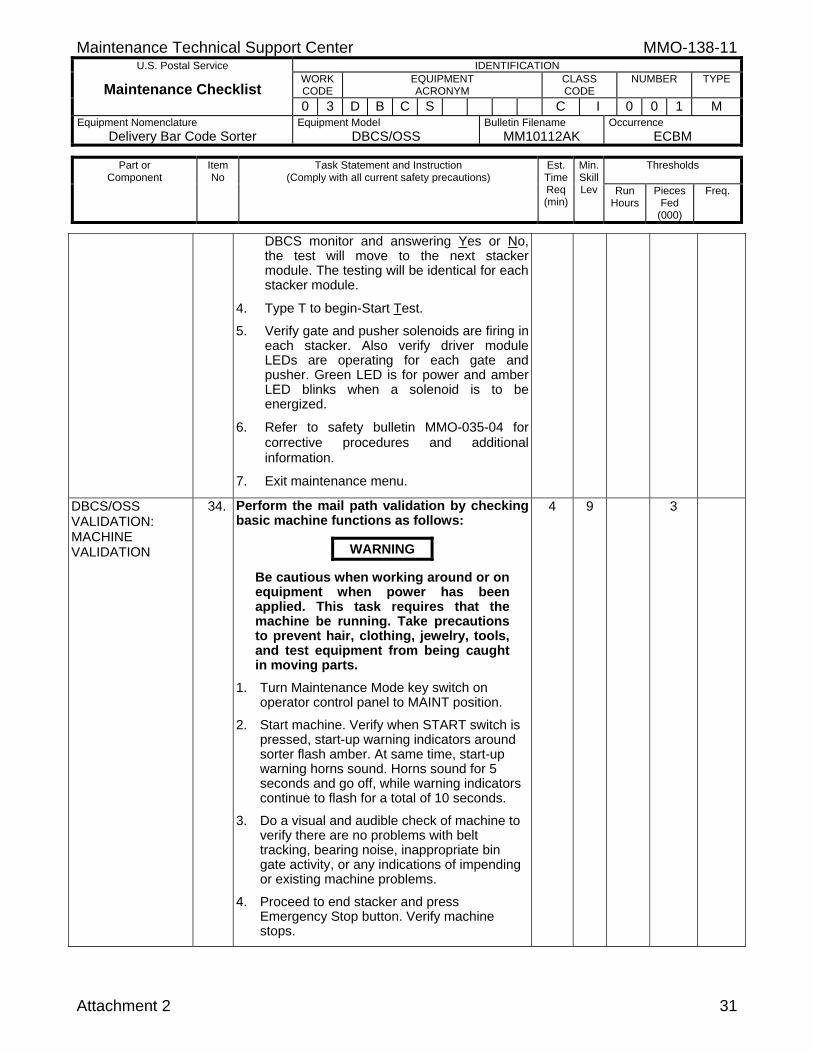
DBCS monitor and answering Yes or No, the test will move to the next stacker module. The testing will be identical for each stacker module.
4. Type T to begin-Start Test. 5. Verify gate and pusher solenoids are firing in
each stacker. Also verify driver module LEDs are operating for each gate and pusher. Green LED is for power and amber LED blinks when a solenoid is to be energized.
6. Refer to safety bulletin MMO-035-04 for corrective procedures and additional information.
7. Exit maintenance menu.
DBCS/OSS VALIDATION: MACHINE VALIDATION
34. Perform the mail path validation by checking basic machine functions as follows:
WARNING
Be cautious when working around or on equipment when power has been applied. This task requires that the machine be running. Take precautions to prevent hair, clothing, jewelry, tools, and test equipment from being caught in moving parts.
1. Turn Maintenance Mode key switch on operator control panel to MAINT position.
2. Start machine. Verify when START switch is pressed, start-up warning indicators around sorter flash amber. At same time, start-up warning horns sound. Horns sound for 5 seconds and go off, while warning indicators continue to flash for a total of 10 seconds.
3. Do a visual and audible check of machine to verify there are no problems with belt tracking, bearing noise, inappropriate bin gate activity, or any indications of impending or existing machine problems.
4. Proceed to end stacker and press Emergency Stop button. Verify machine stops.
4 9 3

MMO-138-11 Maintenance Technical Support Center
U.S. Postal Service IDENTIFICATION
Maintenance Checklist WORK CODE
EQUIPMENT ACRONYM
CLASS CODE
NUMBER TYPE
0 3 D B C S C I 0 0 1 M Equipment Nomenclature
Delivery Bar Code Sorter Equipment Model
DBCS/OSS Bulletin Filename
MM10112AK Occurrence
ECBM
Thresholds
Part or Component
Item No
Task Statement and Instruction (Comply with all current safety precautions)
Est. Time Req (min)
Min. Skill Lev Run
Hours
Pieces Fed
(000)
Freq.
32 Attachment 2
5. If machine fails to stop, notify supervisor. Refer to the most recent Maintenance Management Order, currently MMO-002-03, concerning failure to stop. www.mtsc.usps.gov/pdf/mmo/2003/mmo00203.pdf
6. De-activate E-Stop and turn Maintenance Mode switch back to NORMAL on operator control panel.
DBCS/OSS VALIDATION: LABEL PRINTER
35. Check label printer. Verify label quality.
WARNING
Be cautious when working around or on equipment when power has been applied.
1. On label printer, press LINE FEED button one time. Label printer will print out test label.
2. Verify test label has good quality print (not blurred) and is readable to human eye.
3. If the quality of the print is unacceptable, write a work order to troubleshoot and/or clean the thermal head using cleaning kit (NSN 7930-07-000-1593).
2 7 3
DBCS/OSS VALIDATION: WFOV TEST DECK
36. Run WFOV test deck (NSN 3915-06-000-8292) as follows:
WARNING
Be cautious when working around or on equipment when power has been applied. This task requires that the machine be running. Take precautions to prevent hair, clothing, jewelry, tools, and test equipment from being caught in moving parts.
1. Set up machine in DBCS Mode.
2. Load Run information.
3. Enter Operation number (750).
4. Select F2 to accept.
5. Load sort plan and run 400 piece test deck.
4 9 3
Maintenance Technical Support Center MMO-138-11 U.S. Postal Service IDENTIFICATION
Maintenance Checklist WORK CODE
EQUIPMENT ACRONYM
CLASS CODE
NUMBER TYPE
0 3 D B C S C I 0 0 1 M Equipment Nomenclature
Delivery Bar Code Sorter Equipment Model
DBCS/OSS Bulletin Filename
MM10112AK Occurrence
ECBM
Thresholds
Part or Component
Item No
Task Statement and Instruction (Comply with all current safety precautions)
Est. Time Req (min)
Min. Skill Lev Run
Hours
Pieces Fed
(000)
Freq.
Attachment 2 33
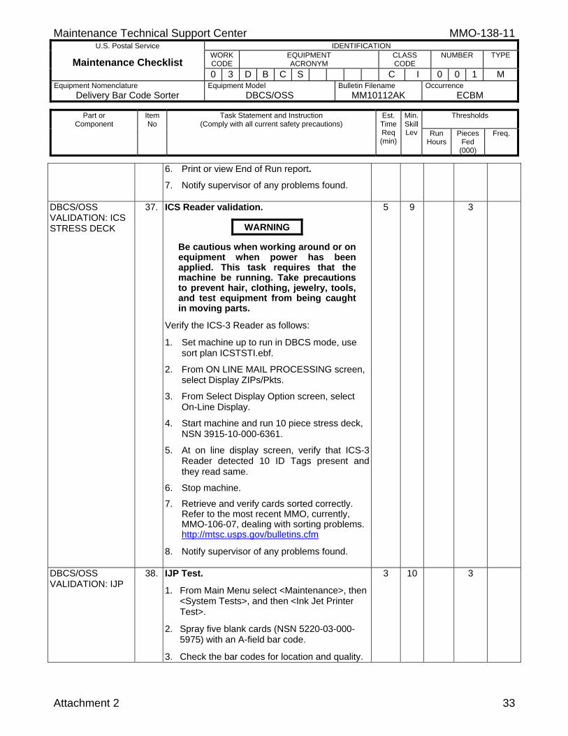
6. Print or view End of Run report.
7. Notify supervisor of any problems found.
DBCS/OSS VALIDATION: ICS STRESS DECK
37. ICS Reader validation.
WARNING
Be cautious when working around or on equipment when power has been applied. This task requires that the machine be running. Take precautions to prevent hair, clothing, jewelry, tools, and test equipment from being caught in moving parts.
Verify the ICS-3 Reader as follows:
1. Set machine up to run in DBCS mode, use sort plan ICSTSTI.ebf.
2. From ON LINE MAIL PROCESSING screen, select Display ZIPs/Pkts.
3. From Select Display Option screen, select On-Line Display.
4. Start machine and run 10 piece stress deck, NSN 3915-10-000-6361.
5. At on line display screen, verify that ICS-3 Reader detected 10 ID Tags present and they read same.
6. Stop machine.
7. Retrieve and verify cards sorted correctly. Refer to the most recent MMO, currently, MMO-106-07, dealing with sorting problems. http://mtsc.usps.gov/bulletins.cfm
8. Notify supervisor of any problems found.
5 9 3
DBCS/OSS VALIDATION: IJP
38. IJP Test.
1. From Main Menu select <Maintenance>, then <System Tests>, and then <Ink Jet Printer Test>.
2. Spray five blank cards (NSN 5220-03-000-5975) with an A-field bar code.
3. Check the bar codes for location and quality.
3 10 3

MMO-138-11 Maintenance Technical Support Center
U.S. Postal Service IDENTIFICATION
Maintenance Checklist WORK CODE
EQUIPMENT ACRONYM
CLASS CODE
NUMBER TYPE
0 3 D B C S C I 0 0 1 M Equipment Nomenclature
Delivery Bar Code Sorter Equipment Model
DBCS/OSS Bulletin Filename
MM10112AK Occurrence
ECBM
Thresholds
Part or Component
Item No
Task Statement and Instruction (Comply with all current safety precautions)
Est. Time Req (min)
Min. Skill Lev Run
Hours
Pieces Fed
(000)
Freq.
34 Attachment 2
NOTE
Right edge of letter to left framing bar should be 4 1/8" to 4 1/4". Bottom of bars should be even and 1/4" ± 1/16" above bottom edge.
4. Write a work order if adjustments are needed.
DBCS/OSS VALIDATION: UAA INTERCEPT BARCODE
39. Verify that the OCR engine in the DBCS mode can intercept UAA mail.
WARNING
Be cautious when working around or on equipment when power has been applied. This task requires that the machine be running. Take precautions to prevent hair, clothing, jewelry, tools, and test equipment from being caught in moving parts.
Using the Xanadu Test Deck, NSN 9310-08-000-3864, P/N 66.1026.034-00, do the following from the Main Menu:
1. Select Mode Select.
2. Select DBCS.
3. Load Run Information.
4. Enter Operation Number (750).
5. Select F2 to accept.
6. Load a sortplan that has a confirmed UAA pocket assigned (ParsSpecial Pockets.ebf assigns pocket 39 for UAA).
7. Start mail processing and run UAA test deck.
8. Print or view the End of Run report.
9. Calculate the intercept rate (# confirmed UAA test pieces divided by the total # of test pieces fed, multiplied by 100).
10. Verify that at least 90% of the UAA test deck was intercepted.
11. Log off the system computer.
9 9 1100

Maintenance Technical Support Center MMO-138-11 U.S. Postal Service IDENTIFICATION
Maintenance Checklist WORK CODE
EQUIPMENT ACRONYM
CLASS CODE
NUMBER TYPE
0 3 D B C S C I 0 0 1 M Equipment Nomenclature
Delivery Bar Code Sorter Equipment Model
DBCS/OSS Bulletin Filename
MM10112AK Occurrence
ECBM
Thresholds
Part or Component
Item No
Task Statement and Instruction (Comply with all current safety precautions)
Est. Time Req (min)
Min. Skill Lev Run
Hours
Pieces Fed
(000)
Freq.
Attachment 2 35
FINAL CLEAN UP 40. Clean up.
Ensure all tools, lubricants, rags, etc., are removed from the work area. Report all deficiencies to supervisor.
2 ALL
MMO-138-11 Maintenance Technical Support Center
U.S. Postal Service IDENTIFICATION
Maintenance Checklist WORK CODE
EQUIPMENT ACRONYM
CLASS CODE
NUMBER TYPE
0 3 D B C S C I 0 0 1 M Equipment Nomenclature
Delivery Bar Code Sorter Equipment Model
DBCS/OSS Bulletin Filename
MM10112AK Occurrence
ECBM
Thresholds
Part or Component
Item No
Task Statement and Instruction (Comply with all current safety precautions)
Est. Time Req (min)
Min. Skill Lev Run
Hours
Pieces Fed
(000)
Freq.
36 Attachment 2
THIS PAGE BLANK
Maintenance Technical Support Center MMO-138-11
Attachment 3 1
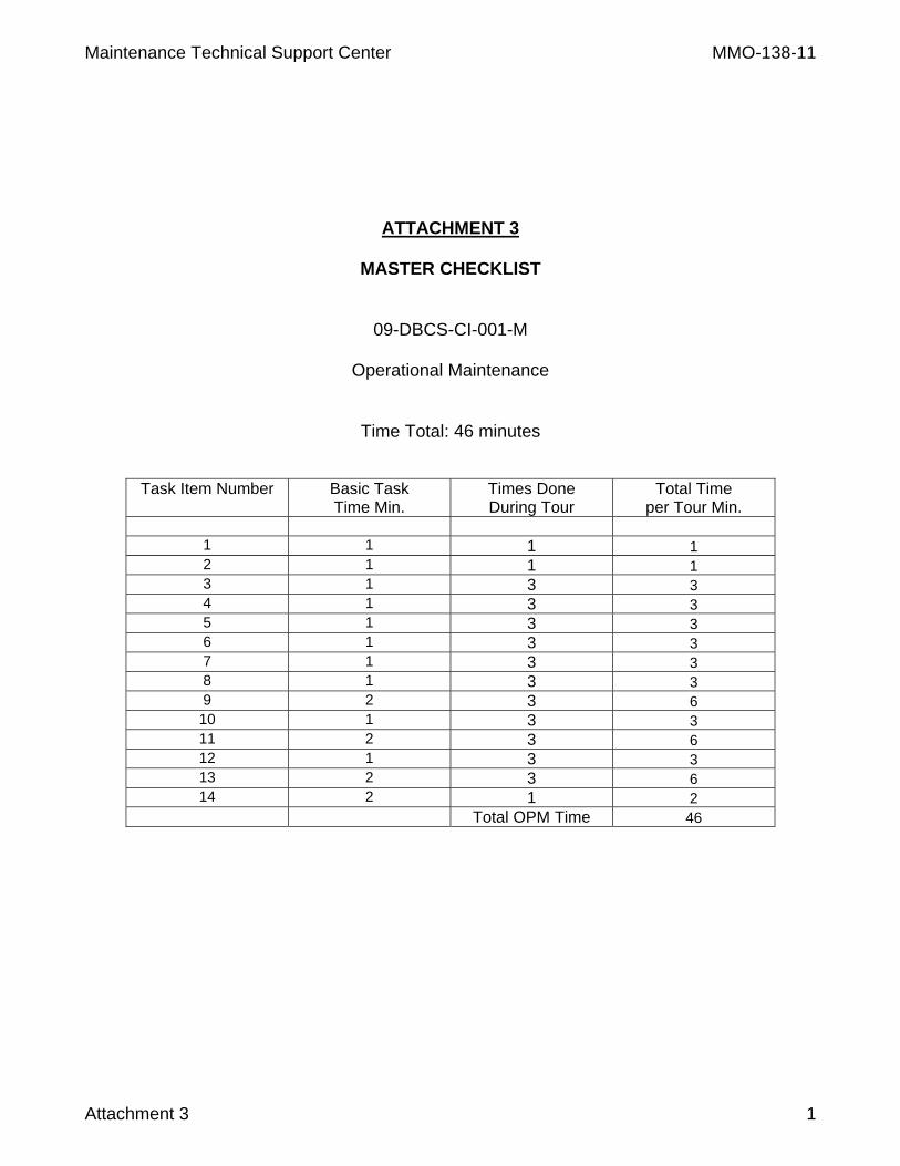
ATTACHMENT 3
MASTER CHECKLIST
09-DBCS-CI-001-M
Operational Maintenance
Time Total: 46 minutes
Task Item Number Basic Task Time Min.
Times Done During Tour
Total Time per Tour Min.
1 1 1 1 2 1 1 1 3 1 3 3 4 1 3 3 5 1 3 3 6 1 3 3 7 1 3 3 8 1 3 3 9 2 3 6 10 1 3 3 11 2 3 6 12 1 3 3 13 2 3 6 14 2 1 2
Total OPM Time 46

MMO-138-11 Maintenance Technical Support Center U.S. Postal Service IDENTIFICATION
Maintenance Checklist WORK CODE
EQUIPMENT ACRONYM
CLASS CODE
NUMBER TYPE
0 9 D B C S C I 0 0 1 M Equipment Nomenclature
Delivery Bar Code Sorter Equipment Model
DBCS/OSS Bulletin Filename
MM10112AK Occurrence
Tourly
Thresholds
Part or Component
Item No
Task Statement and Instruction (Comply with all current safety precautions)
Est. Time Req (min)
Min. Skill Lev Run
Hours
Pieces Fed
(000)
Freq.
Attachment 3 2
SAFETY STATEMENT
1. COMPLY WITH ALL SAFETY PRECAUTIONS. Disconnect power and apply lockouts when required by this instruction. Refer to current local lockout procedures to properly shutdown and lockout this machine. Open equipment and inspect dust conditions. Check for suspicious dust or unusual debris. If any unusual substance is found notify supervisor prior to proceeding with any further action on the equipment.
THE USE OF COMPRESSED OR BLOWN AIR IS PROHIBITED. When cleaning is required, an alternative cleaning method such as a HEPA filtered vacuum cleaner or a damp rag must be used in place of compressed or blown air. A lint-free cloth or brush may be used on optical equipment only when other cleaning methods cannot be used. Report safety deficiencies to your supervisor immediately upon detection. WARNING FOR EWP/PPE: Steps contained in this bulletin may require the use of Personal Protective Equipment (PPE). Refer to the current Electrical Work Plan (EWP) MMO for appropriate PPE requirements.
1 All T
DBCS/OSS OPM: MACHINE LOGBOOK
2. At the beginning of the operation examine machine log.
WARNING
Be cautious when working around or on equipment when power has been applied. This task requires that the machine be running. Take precautions to prevent hair, clothing, jewelry, tools, and test equipment from being caught in moving parts.
Examine log and bring forward any unresolvedproblems from the previous tour.
NOTE
Operational checks must be made with machine processing mail in a normal operating mode.
1 9 T
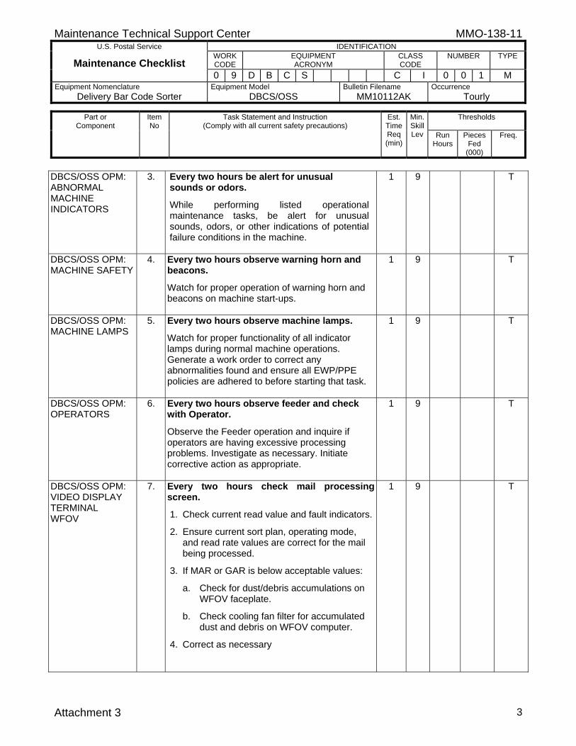
Maintenance Technical Support Center MMO-138-11 U.S. Postal Service IDENTIFICATION
Maintenance Checklist WORK CODE
EQUIPMENT ACRONYM
CLASS CODE
NUMBER TYPE
0 9 D B C S C I 0 0 1 M Equipment Nomenclature
Delivery Bar Code Sorter Equipment Model
DBCS/OSS Bulletin Filename
MM10112AK Occurrence
Tourly
Thresholds
Part or Component
Item No
Task Statement and Instruction (Comply with all current safety precautions)
Est. Time Req (min)
Min. Skill Lev Run
Hours
Pieces Fed
(000)
Freq.
Attachment 3 3
DBCS/OSS OPM: ABNORMAL MACHINE INDICATORS
3. Every two hours be alert for unusual sounds or odors.
While performing listed operational maintenance tasks, be alert for unusual sounds, odors, or other indications of potential failure conditions in the machine.
1 9 T
DBCS/OSS OPM: MACHINE SAFETY
4. Every two hours observe warning horn and beacons.
Watch for proper operation of warning horn and beacons on machine start-ups.
1 9 T
DBCS/OSS OPM: MACHINE LAMPS
5. Every two hours observe machine lamps.
Watch for proper functionality of all indicator lamps during normal machine operations. Generate a work order to correct any abnormalities found and ensure all EWP/PPE policies are adhered to before starting that task.
1 9 T
DBCS/OSS OPM: OPERATORS
6. Every two hours observe feeder and check with Operator.
Observe the Feeder operation and inquire if operators are having excessive processing problems. Investigate as necessary. Initiate corrective action as appropriate.
1 9 T
DBCS/OSS OPM: VIDEO DISPLAY TERMINAL WFOV
7. Every two hours check mail processing screen.
1. Check current read value and fault indicators.
2. Ensure current sort plan, operating mode, and read rate values are correct for the mail being processed.
3. If MAR or GAR is below acceptable values:
a. Check for dust/debris accumulations on WFOV faceplate.
b. Check cooling fan filter for accumulated dust and debris on WFOV computer.
4. Correct as necessary
1 9 T
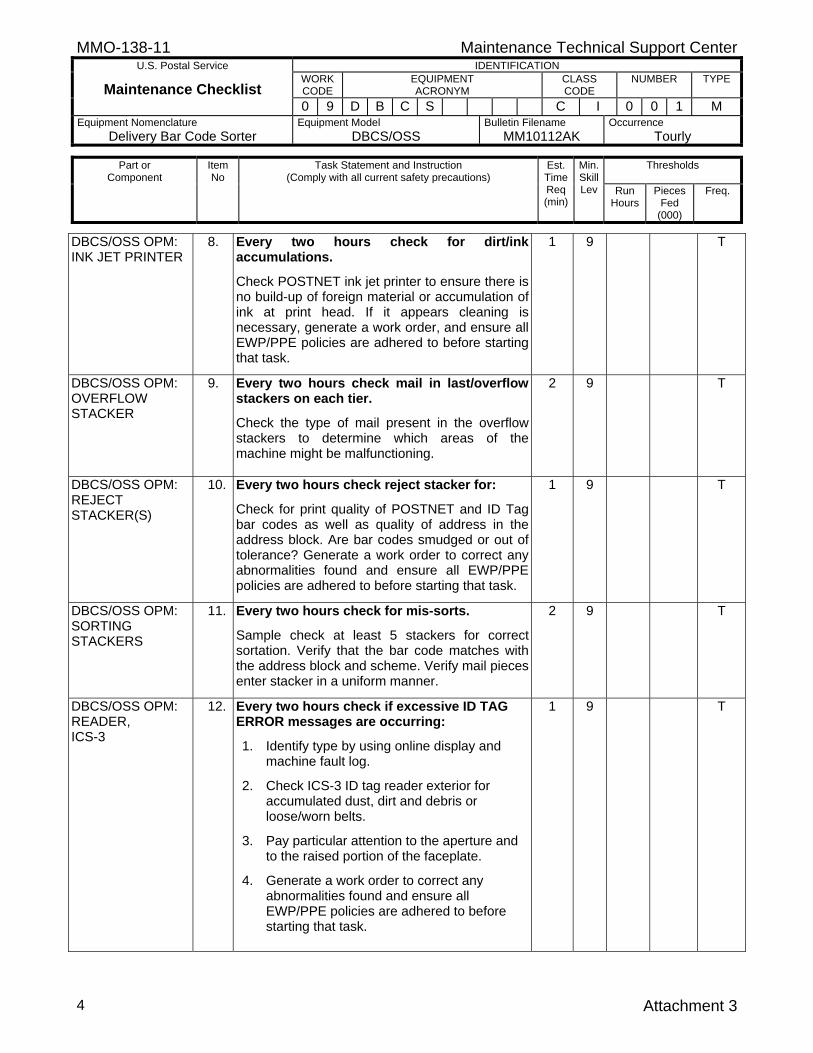
MMO-138-11 Maintenance Technical Support Center U.S. Postal Service IDENTIFICATION
Maintenance Checklist WORK CODE
EQUIPMENT ACRONYM
CLASS CODE
NUMBER TYPE
0 9 D B C S C I 0 0 1 M Equipment Nomenclature
Delivery Bar Code Sorter Equipment Model
DBCS/OSS Bulletin Filename
MM10112AK Occurrence
Tourly
Thresholds
Part or Component
Item No
Task Statement and Instruction (Comply with all current safety precautions)
Est. Time Req (min)
Min. Skill Lev Run
Hours
Pieces Fed
(000)
Freq.
Attachment 3 4
DBCS/OSS OPM: INK JET PRINTER
8. Every two hours check for dirt/ink accumulations.
Check POSTNET ink jet printer to ensure there is no build-up of foreign material or accumulation of ink at print head. If it appears cleaning is necessary, generate a work order, and ensure all EWP/PPE policies are adhered to before starting that task.
1 9 T
DBCS/OSS OPM: OVERFLOW STACKER
9. Every two hours check mail in last/overflow stackers on each tier.
Check the type of mail present in the overflow stackers to determine which areas of the machine might be malfunctioning.
2 9 T
DBCS/OSS OPM: REJECT STACKER(S)
10. Every two hours check reject stacker for:
Check for print quality of POSTNET and ID Tag bar codes as well as quality of address in the address block. Are bar codes smudged or out of tolerance? Generate a work order to correct any abnormalities found and ensure all EWP/PPE policies are adhered to before starting that task.
1 9 T
DBCS/OSS OPM: SORTING STACKERS
11. Every two hours check for mis-sorts.
Sample check at least 5 stackers for correct sortation. Verify that the bar code matches with the address block and scheme. Verify mail pieces enter stacker in a uniform manner.
2 9 T
DBCS/OSS OPM: READER, ICS-3
12. Every two hours check if excessive ID TAG ERROR messages are occurring:
1. Identify type by using online display and machine fault log.
2. Check ICS-3 ID tag reader exterior for accumulated dust, dirt and debris or loose/worn belts.
3. Pay particular attention to the aperture and to the raised portion of the faceplate.
4. Generate a work order to correct any abnormalities found and ensure all EWP/PPE policies are adhered to before starting that task.
1 9 T
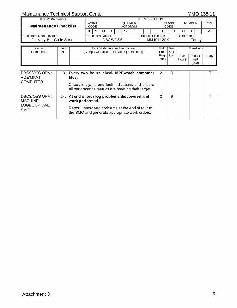
Maintenance Technical Support Center MMO-138-11 U.S. Postal Service IDENTIFICATION
Maintenance Checklist WORK CODE
EQUIPMENT ACRONYM
CLASS CODE
NUMBER TYPE
0 9 D B C S C I 0 0 1 M Equipment Nomenclature
Delivery Bar Code Sorter Equipment Model
DBCS/OSS Bulletin Filename
MM10112AK Occurrence
Tourly
Thresholds
Part or Component
Item No
Task Statement and Instruction (Comply with all current safety precautions)
Est. Time Req (min)
Min. Skill Lev Run
Hours
Pieces Fed
(000)
Freq.
Attachment 3 5
DBCS/OSS OPM: ACE/MKAT COMPUTER
13. Every two hours check MPEwatch computer files.
Check for, jams and fault indications and ensure all performance metrics are meeting their target.
2 9 T
DBCS/OSS OPM: MACHINE LOGBOOK AND SMO
14. At end of tour log problems discovered and work performed.
Report unresolved problems at the end of tour to the SMO and generate appropriate work orders.
2 9 T

![MMO 028-97[1]](https://static.fdocuments.in/doc/165x107/551542b8497959111e8b4cdc/mmo-028-971.jpg)


![MMO: Payload AIV MMO-SWG #3 [March 2006] -1- C. Noshi/RASC, Kyoto Univ. MMO Mercury Magnetospheric Orbiter AIV (Assembly, Integration, Verification) for.](https://static.fdocuments.in/doc/165x107/56649e4e5503460f94b44dc0/mmo-payload-aiv-mmo-swg-3-march-2006-1-c-noshirasc-kyoto-univ-mmo.jpg)