Maintenance Schedule for Substation
28
-
Upload
sajid-shaikh -
Category
Documents
-
view
114 -
download
6
Transcript of Maintenance Schedule for Substation


OPERATION AND COMPREHENSIVE MAINTENANCE FOR SUB-STATION
ELIGIBILITY CONDITIONS
1. The firm shall have establishment and maintenance setup located at Mumbai or suburban Mumbai. The firm shall have Solvency certificate from the Bankers for a minimum of Rs. 20 lakhs, latest Chartered Accountants Certificate, valid Electrical Contractor’s licence and round the clock fixed and Mobile telephone number.
2. a) Registered Electrical Contractors of BSNL/CPWD/MES subject to their financial limits corresponding to the estimated cost of work for 12 months.
ORb) Registered Electrical Contractors of highest class in State PWD.
ANDa) Firms who have carried out satisfactorily at least 1 work (Cost of the work
shall not be less than 75% of 12 month’s estimated cost) of Maintenance in MTNL/BSNL comprising of either Sub station or Engine Alternator service as part of scope of work. Also firm's aggregate turn over for the last 3 years shall not be less than Rs. 50 lakhs reckoned from date of notice inviting tender.
1. The firm shall have following valid certificates/ registration:-
i. Sales Tax/ VAT registration certificate.
ii. EPF registration.
iii. ESIC registration.
iv. Works Contract registration number and address of WC Tax Assessing Authority as a proof of their establishment in Mumbai/ Navi Mumbai region.
v. Service Tax registration.

SUB-STATION MAINTENANCE DOCUMENT
1. Scope of Maintenance:
1.1 Ensuring that HT Panel, Transformer, LT panels, capacitor panels & out door structure as well as connecting cables/ducts, constituting the substation are maintained in healthy & clean condition,
1.2 Monitoring on continuous basis power factor & peak load and ensuring that these are maintained within limits to avoid penalty.
1.3 To perform maintenance tasks as per schedule given below.
1.4 To disconnect total electric supply and or individual loads in case of emergent situation to avoid/ limit damage.
1.5 To ensure continuous power supply and in case of breakdowns take steps to ensure restoration at the earliest.
2. Tasks to be performed within first 15 days
2.1Identify a persons(s) with necessary competence to be responsible for substation maintenance
2.2The person(s) deputed for substation job should
2.2.1 Know how to treat the persons suffering from electric shock/ burn etc.
2.2.2 Be able to operate fire extinguisher.
2.2.3 Make himself familiar with the distribution scheme the switches controlling
various loads and also importance.
2.2.4 Clearly understand what is to be done in case of an emergency. This should
be done in consultation with Engineer In-charge.
2.2.5 Carry out general inspection with a view to identify shortcoming if any in the
sub stations installation.
2.3Check all the switches & meters for proper operation
2.4Check availability and working of fire extinguishers at earmarked locations.
2.5Check operation and calibration of all the safety devices like relays and fuses.
2.6Check the earthing system for the proper earth values & continuity of earthing system.
2.7Check insulation value of oil in all the equipments.
2.8Carry out megger test.
2.9Check oil level in all the equipment to ensure proper levels.
2.10 Check power factor meter, maximum demand meter for proper functioning
2.11 Check the tripping of the HT Panel including batteries etc. for proper functioning.
2.12 Check all the electrical connections for proper tightness.
2.13 All results of above inspection to be recorded and brought to the notice of
Engineer-in-Charge specially highlighting shortcomings for necessary action.
2.14 All rectification, replacements, calibration and testing costs at the time of taking
over the maintenance at beginning shall be borne by the department.
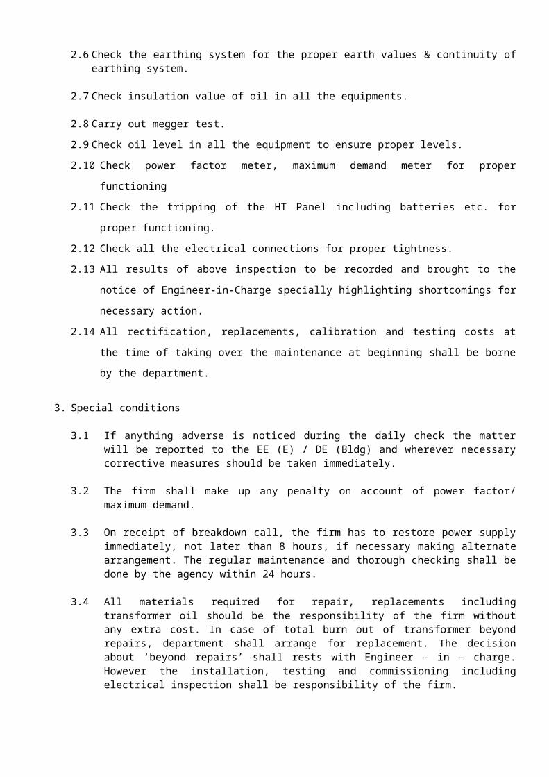
3. Special conditions
3.1 If anything adverse is noticed during the daily check the matter will be reported to the EE (E) / DE (Bldg) and wherever necessary corrective measures should be taken immediately.
3.2 The firm shall make up any penalty on account of power factor/ maximum demand.
3.3 On receipt of breakdown call, the firm has to restore power supply immediately, not later than 8 hours, if necessary making alternate arrangement. The regular maintenance and thorough checking shall be done by the agency within 24 hours.
3.4 All materials required for repair, replacements including transformer oil should be the responsibility of the firm without any extra cost. In case of total burn out of transformer beyond repairs, department shall arrange for replacement. The decision about ‘beyond repairs’ shall rests with Engineer – in – charge. However the installation, testing and commissioning including electrical inspection shall be responsibility of the firm.
3.5 Tests are to be carried out before handing over the maintenance as per the yearly test schedule attached.
3.6 The agency will be responsible for all rectification, replacements, calibration and testing costs and hand over the installation to the new agency in healthy condition. In case the same agency continues for operation and maintenance of the installation, the agency will carryout these activities as per the maintenance schedule.

MAINTENANCE SCHEDULEFOR CAST RESIN TRANSFORMER
Sr. No.
Inspection Frequency
Items to be inspected
Inspection Notes
1 Hourly Ambient Temperature Check ambient temperature2 Hourly Winding Temperature Check WTI temperature3 Hourly Load (Amperes) Check load current4 Hourly Incoming voltage Check against rated figures
5 After every tap change/ half
yearly
HT tap links Check that links are fully tightened and locked
6 Daily WTI (Winding Temperature Indicator)WTR (Winding Temperature Relay)
Check RTD for healthinessCheck alarm & trip thermisters for healthiness
7 Half yearly Enclosure & marshalling box
(a) Check for cowebs, dust, dirt deposits
(b) Painting8 Half yearly Core & coil assembly (a) Check for cowebs, dust, dirt
deposits(b) Painting
9 Half yearly HT/ LT connections Check for tightness of nut bolts
10 Yearly Core & coil assembly Check for tightness of core bolts/ tie rod nuts
11 Yearly Earth resistance Check earth resistance
12 Yearly Transformer Check ratio (Refer to manufacturer if necessary)
13 Yearly Enclosure Side covers, cable boxes, marshalling box
14 Yearly Relays, its alarm & trip contacts, their circuits
(a) Check relays, its contacts, their operation
(b) Check alarm/ trip circuit operation for alarm
15 Yearly (or as found necessary)
Cooling fan (only for forced air cooled CRT)
Motor bearing
16 Yearly HT/LT bushings (a) Examine for dirt deposits(b) Examine for cracks/ damages

RECORD OF MEASUREMENTS FOR SUBSTATION - 3 HOURLY (BY OPERATOR)
DEPT.MV PANEL EB PANELIncomer-1 TR-1 Incomer-2 TR-2
Hou
rs
Am
bie
nt
tem
p.
Cu
rren
t
Volt
ag
e
Tem
pera
ture
Oil/
Win
din
g (
Dry
ty
pe)
Cu
rren
t
Volt
ag
e
Tem
pera
ture
Oil/
Win
din
g (
Dry
ty
pe)
PF
KW
h
KV
Ah
PF
MD
Perm
issib
le
ran
ge
85%
0f
full
load
cu
rren
t
+/-
5%
of
415
Volt
s
65 o
C (
Oil)
105°C
(D
ry
typ
e)
85%
0f
full
load
cu
rren
t
+/-
5%
of
415
Volt
s
65 o
C (
Oil)
105°C
(D
ry
typ
e)
0 .
912.00
AM 3.00 AM
6.00 AM
9.00 AM
12.00 PM
3.00 PM
6.00 PM
9.00 PM

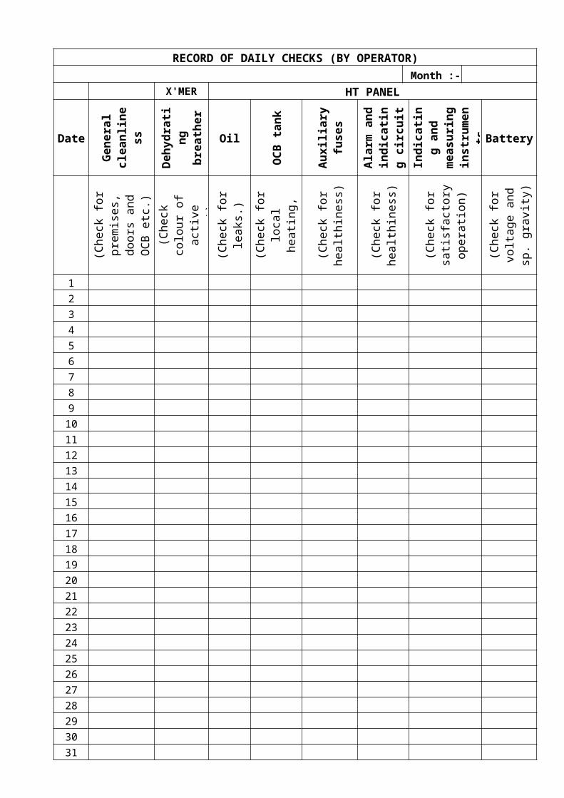
RECORD OF DAILY CHECKS (BY OPERATOR)Month :-
X'MER HT PANEL
Date
Gen
era
l cle
an
lin
ess
Deh
yd
rati
ng
b
reath
er
Oil
OC
B t
an
k
Au
xilia
ry
fuses
Ala
rm
an
d
ind
icati
ng
cir
cu
itIn
dic
ati
ng
an
d
measu
rin
g
instr
um
en
tsBattery
(Check
for
pre
mis
es,
doors
and O
CB
etc
.)
(Check
colo
ur
of
act
ive
agent)
(Check
for
leaks
.)
(Check
for
loca
l h
eati
ng
, unusu
al sm
ell
/ nois
e)
(Check
for
healt
hin
ess
)
(Check
for
healt
hin
ess
)
(Check
for
sati
sfact
ory
opera
tion)
(Check
for
volt
age a
nd
sp
. gra
vit
y)
1 2 3 4 5 6 7 8 9
10 11 12 13 14 15 16 17 18 19 20 21 22 23 24 25 26 27 28 29 30 31
RECORD OF WEEKLY CHECKS (BY OPERATOR)
Year :- Item to be inspected :- Oil level of TransformerInspection note :- Check against oil level mark Weeks
Month 1 2 3 4 5Remark
s
January
February
March
April
May
June
July
August
September
October
November
December

RECORD OF MONTHLY CHECKS (BY OPERATOR)Year :- Months
Sl. No.
Items to be Inspected
Inspection Note JanFeb
Mar
AprMay
Jun JulAug
Sep
OctNov
Dec
LT PANEL1 Connections Check for
tightness and over heating, unusual smell or noise
2 Busbar/Cable joints
Examine insulators, busbar contacts, cable joints etc for overall condition
3 Indicating and measuring instruments
Check for satisfactory operation
4 Earthing Check for proper earthing
LT CIRCUIT BREAKER1 General
conditionsCheck for premises, doors and locks etc.
2 Connections Check for tightness and over heating
3 Load Check for load conditions and match the CT ratings
4 Busbar/Cable joints
Examine insulators, busbar contacts, cable joints etc for overall condition
5 Alarm and indicating circuit
Check for continuity and proper operation
6 Indicating and measuring instruments
Check for satisfactory operation
7 Earthing Check for proper earthing
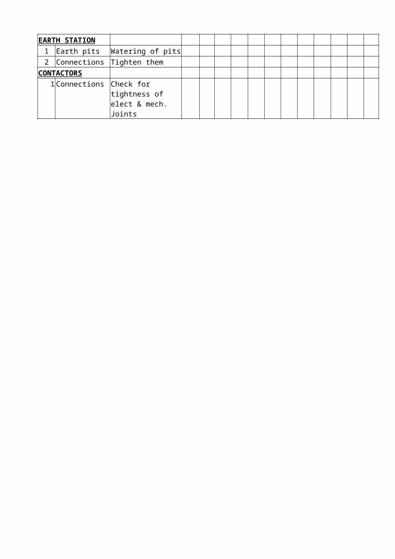
EARTH STATION1 Earth pits Watering of pits2 Connections Tighten them
CONTACTORS1 Connections Check for
tightness of elect & mech. Joints

RECORD OF QUARTERLY CHECKS (BY AMC)Year :- Quarter
Sl. No.
Items to be Inspected Inspection Note 1 2 3 4
TRANSFORMER1 Oil Check dielectric strength (>30
KV/mm) & pH value (≥ 5.5)2 Bushing Examine for cracks and dirt deposits3 Connections Examine for looseness4 Explosion vent Examine the packing
HT PANEL1 Cleaning Remove all loose external dirt with
dry cloth2 Operating mechanisms Check for trouble free operation
3 Interlocking device Check for healthy operation4 Isolating contacts /
ShuttersCheck for proper functioning
5 Cable boxes Check for sealing arrangements for filling holes and compound for cracks
6 Insulators Check for signs of damage7 Aux. contacts/
switches/fusesCheck for any deterioration
8 Contacts Check for alignment and pressureLT CIRCUIT BREAKER
1 Cleaning Remove all loose external dirt with dry cloth
2 Fastening and clamps Check for tightness
3 Operating mechanisms Check for trouble free operation
4 Interlocking device Check for healthy operation5 Isolating contacts /
ShuttersCheck for proper functioning
6 Arc chutes Check for carbon formation, damage etc.
7 Insulators Check for signs of damage8 Aux. contacts/ switches Check for any deterioration9 Contacts Check for alignment and pressure
10 CTs & relays Check for settings & operationLT PANEL
1 Cleaning Remove all loose external dirt with dry cloth
2 Fastening and clamps Check for tightness
3 Operating mechanisms Check for trouble free operation
4 Interlocking device Check for healthy operation5 SFU/FSU Check for operation & tightness6 Isolating contacts /
ShuttersCheck for proper functioning
7 Aux. contacts/switches Check for any deterioration
Sl. No.
Items to be Inspected Inspection Note 1 2 3 4
CAPACITOR PANEL1 Connections Check for tightness, corrosion and
breakage2 Busbar/Cable joints Examine insulators, busbar contacts,
cable joints etc for overall condition3 Indicating and
measuring instrumentsCheck for satisfactory operation
4 Capacitors Check for leakages & contacts5 External fuses Check for condition6 Insulation Measure insulation resistance
between phases and phase to earth7 Automatic power factor
relayCheck for setting and operation
OUTDOOR STRUCTURE
1 Poles Check for damages, erosion and corrosion, leaning due to overloading etc.
2 Fastening and clamps Check for tightness
3 Insulators and fittings Check for cracks, flash over marks and tilting
4 Conductors and earth wire
Check for proper supports, intactness, sag, joints etc.
5 Jumpers and other accessories
Check for proper supports , clearances , proper insulation and loose joints etc.
6 Air break switch Check for proper functioning, over heating, pitting on the contacts, earth connections, locking arrangement, complete fitting of male and female contacts, arcing horns etc.
7 Lightning arresters Check for deterioration of porcelain, intactness of line and earth connection, indication of fused or spark over etc.
8 Earthing system Check for tightness CONTACTORS
1 Contacts Check for over heating marks, damage to insulation through over heating, contactor hum/chattering

RECORD OF YEARLY CHECKS (BY AMC)Sl. No.
Items to be Inspected
Inspection Note 1 2 3 4 5
TRANSFORMER1 Gasket joints Examine for tightness 2 Cable boxes Check for sealing arrangements for
filling holes and compound for cracks
3 Earth resistance Check for value, earth connections 4 Insulation resistance Check for healthiness of insulation 5 Temperature
indicationCheck pockets of thermometer
6 Paint work Check overall painting HT PANEL
1 Earth resistance Check for value, earth connections 2 CTs & PT’s Check for satisfactory functioning 3 Oil level & quality Examine for dielectric strength & oil
level in tank LT CIRCUIT BREAKER (MCCB)
1 Contacts Clean the contacts with a piece of cloth dipped in Carbon tetra Chloride and TrichloroEthyline (for corrosive atmosphere)
2 Contacts After major fault clearance, contact buttons should be cleaned with fine emery paper, after that with piece of cloth dipped in Carbon tetra Chloride and TrichloroEthyline
LT PANEL1 Rubber mats Check for condition 2 Insulators Check for signs of damage 3 Contacts Check for alignment and pressure 4 CT’s & relays Check for settings & operation 5 Insulation Measure insulation resistance
between phases and phase to earth 6 Earthing Check for earth resistance 7 Control wiring, fuses,
protectionCheck for continuity & healthiness
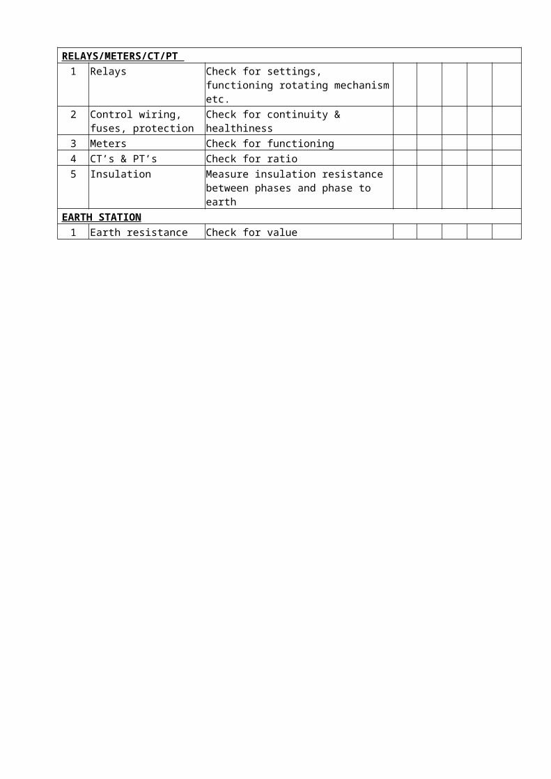
RELAYS/METERS/CT/PT
1 Relays Check for settings, functioning rotating mechanism etc.
2 Control wiring, fuses, protection
Check for continuity & healthiness
3 Meters Check for functioning 4 CT’s & PT’s Check for ratio 5 Insulation Measure insulation resistance
between phases and phase to earth EARTH STATION
1 Earth resistance Check for value

YEARLY TESTING OF INSTALLATION
1. Test for any sign(s) of overloading in respect of H.T. & L.T. equipments
2. Check for existence of any unauthorized temporary installation.3. Check whether the transformer oil samples are being tested
periodically and results recorded in a register.4. Check whether earth resistance is being measured periodically
and results recorded in register.5. Check where lighting arrestors have been provided near the
transformer for protection against lightning.6. Check the condition of service lines, cables, wires, circuit
breakers, isolating switches, protective recording & integrating apparatus and such other fittings.
7. Check if Danger Notice plates in the local language and of the type approved by the electrical inspector are affixed as per rules permanently in conspicuous position.
8. Check safety measures on live lines and apparatus.9. Check whether all circuits and apparatus are so arranged that
there is no danger of any part(s) becoming accidentally charged by any voltage beyond the limits of voltage for which it is intended.
10. Check if first aid boxes or cupboards conspicuously marked and properly equipped are provided and maintained.
11. Check where staff trained in first aid treatment.12. Check if instructions in HINDI, ENGLISH and MARATHI for
restoration of persons suffering from electric shock have been affixed in conspicuous place.
13. Check insulation resistance between conductors and earth in Meg. Ohms.
14. Check if all conductor and apparatus i/c live parts thereof are inaccessible.
15. Check the method adopted to guard L.V. circuits in transformer becoming accidentally charged above its/their normal voltage.
16. Check if trenches inside substation containing cable are filled with non-inflammable material or completely covered with non-inflammable slabs.
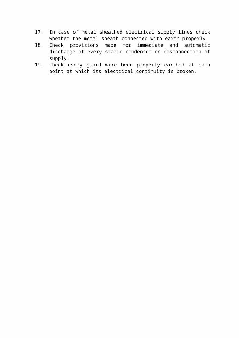
17. In case of metal sheathed electrical supply lines check whether the metal sheath connected with earth properly.
18. Check provisions made for immediate and automatic discharge of every static condenser on disconnection of supply.
19. Check every guard wire been properly earthed at each point at which its electrical continuity is broken.

ANNEXURE – I
A. Details to be supplied before starting the work
1 Name of the Agency
(with Office address):
2 Name of Proprietor/partners
:
3 Telephone No.(s)of the firm
:
4 Name & address of the Supervisor
:
5 24 Hours contact No. :
6 Particulars of the Licence/ Registration
:
B. Detail of staff to be posted at site.
Sr. No.
Name and Address
EPF no. of Operator

Annexure - II
COMPLAINT REGISTER
Sr. No.
Date &Time of
complaint
Nature of complaint
LocationTime & Date of attending complaint
Cause of fault
Material used
Dated Signature of complainant
Dated Signature of
Firm Representative
ANNEXURE – III
Programme for Periodical Maintenance for the month of __________
Name of contractor: __________________
Agreement No. : _____________________
Name of Division: _________________
Location: __________________
Sr. No.
Name of Service
Maintenance activity with
requirements of materials
Remark
(Contractor) SDE / DE

ANNEXURE – IV
Actual Periodical Maintenance carried out in the month of __________
Name of contractor: __________________
Agreement No. : _____________________
Name of Sub Division: _________________
Location: __________________
Sr. No.
Name of service
Periodical maintenance
actually carried out
Resultssatisfactory/unsatisfactor
y
Remarks
(Contractor) SDE / DE
ANNEXURE V
LOG BOOK OF SUBSTATION (INDOOR)DATE : __________
TIMEH. T.
VoltageIn KV
HT CurrentIn Amp.
Incoming
Transformer – I Transformer – II Total Power Remarks
Voltage CurrentTemp
in° C
Voltage CurrentTemp in° C
MD in
KVA
Kwh ( a)
Kvah( b )
P.F.(a/b)
RY
YB
BR
R Y B RY
YB
BR
R Y B RY
YB
BR
R Y B i) Record no. & duration of Mains failure on each day.
ii) Details of maintenance like, heating of silica gel, dehydration of transformer oil, servicing of LT. ACBs, replacement of HRC fuses, indication lamps & contacts of contactors, etc.
iii) Record of earth resistance.
08.0011.0014.0017.0020.0023.0002.0005.00


ANNEXURE VILOG BOOK OF SUBSTATION (OUTDOOR)
DATE: __________
TIME
Transformer – I Transformer – II Total Power Remarks
Voltage CurrentTemp
in° C
Voltage CurrentTemp in° C
MD in
KVA
Kwh ( a)
Kvah( b )
P.F.(a/b)
RY YB BR R Y B RY
YB BR R Y B i) Record no. & duration of Mains failure on each day.
ii) Details of maintenance like, heating of silica gel, dehydration of transformer oil, servicing of LT ACB’s.
iii) Record of earth resistance.
08.0011.0014.0017.0020.0023.0002.0005.00

Note: 1. Log book shall be checked daily by the Technician/JTO in- charge.2. Log book shall be checked and reviewed by SDE in-charge at least once in a week.3. Log book shall be checked and reviewed by DE in-charge at least once in a fortnight.