Maintenance Manual NDP-20-25 - Alfsen og … filer avd 87/Maintenance_Manual...Doc. No NDP20/25...
45
Doc. No NDP20/25 English - 02 Revised November 2006 MAINTENANCE MANUAL YAMADA AIR-OPERATED DIAPHRAGM PUMPS NDP-20 NDP-25 WARNING • For your own safety, be sure to read these procedures carefully before performing maintenance on this product. After reading this document, be sure to keep it handy for future reference. This maintenance manual covers what you should know about maintenance of the Yamada NDP-20 series and NDP-25 series Diaphragm Pumps. This edition is based on the standards for the June 1998 production run. Remember the specifications are always subject to change; therefore, some of the information in this edition may not apply to new specifications. • Warnings and Cautions For safe use of this product, be sure to note the following: In this document, warnings and cautions are indicated by symbols. These symbols are for those who will operate this product and for those who will be nearby, for safe operation and for prevention of personal injury and property damage. The following warning and caution symbols have the meanings described below. Be sure to remember their meanings. WARNING: If you ignore the warning described and operate the product in an improper manner, there is danger of serious bodily injury or death. CAUTION: If you ignore the caution described and operate the product in an improper manner, there is danger of personal injury or property damage. Furthermore, to indicate the type of danger and damage, the following symbols are also used along with those mentioned above: This symbol indicates a DON’T, and will be accompanied by an explanation on something you must not do. This symbol indicates a DO, and will be accompanied by instructions on something you must do in a certain situation. WARNING • Before starting maintenance work, cut off the feed air and clean the pump. If air pressure or residue remain in the pump, there is danger of explosion, or possible poisoning resulting in serious injury or death if chemicals adhere to the skin or are accidentally swallowed. (For details on cleaning the pump, refer to Chapter 6 of the operating manual.) • When replacing parts, be sure to use the recommended genuine parts or equivalents. Use of other parts may cause a malfunction of the product. CAUTION • When it is instructed that special tools must be used, be sure to use the specified tools. Otherwise, the pump may be damaged. • Refer to 10.1 “Specifications” in the Operating Manual. Also, remember that the pumps is heavy, and extreme care must be taken when lifting it.
Transcript of Maintenance Manual NDP-20-25 - Alfsen og … filer avd 87/Maintenance_Manual...Doc. No NDP20/25...

Doc. No NDP20/25 English - 02
Revised November 2006
MAINTENANCE MANUAL
YAMADA AIR-OPERATED DIAPHRAGM PUMPS NDP-20
NDP-25
WARNING
• For your own safety, be sure to read these procedures carefully before performing maintenance
on this product. After reading this document, be sure to keep it handy for future reference.
This maintenance manual covers what you should know about maintenance of the Yamada NDP-20 series and
NDP-25 series Diaphragm Pumps.
This edition is based on the standards for the June 1998 production run. Remember the specifications are always
subject to change; therefore, some of the information in this edition may not apply to new specifications.
• Warnings and Cautions For safe use of this product, be sure to note the following: In this document, warnings and cautions are indicated
by symbols. These symbols are for those who will operate this product and for those who will be nearby, for safe
operation and for prevention of personal injury and property damage. The following warning and caution
symbols have the meanings described below. Be sure to remember their meanings.
WARNING:
If you ignore the warning described and operate the product in an
improper manner, there is danger of serious bodily injury or death.
CAUTION: If you ignore the caution described and operate the product in an
improper manner, there is danger of personal injury or property damage.
Furthermore, to indicate the type of danger and damage, the following symbols are also used along with those
mentioned above:
This symbol indicates a DON’T, and will be accompanied by an explanation on something
you must not do.
This symbol indicates a DO, and will be accompanied by instructions on something you must
do in a certain situation.
WARNING • Before starting maintenance work, cut off the feed air and clean the pump. If air pressure or residue
remain in the pump, there is danger of explosion, or possible poisoning resulting in serious injury
or death if chemicals adhere to the skin or are accidentally swallowed.
(For details on cleaning the pump, refer to Chapter 6 of the operating manual.)
• When replacing parts, be sure to use the recommended genuine parts or equivalents. Use of other
parts may cause a malfunction of the product.
CAUTION
• When it is instructed that special tools must be used, be sure to use the specified tools.
Otherwise, the pump may be damaged.
• Refer to 10.1 “Specifications” in the Operating Manual. Also, remember that the pumps is
heavy, and extreme care must be taken when lifting it.

2
Table of Contents Page
� Warnings and Cautions......................................................................................................1
� Table of Contents ..............................................................................................................2
1. Principles of operation.......................................................................................................4
2. Tools, etc...........................................................................................................................
General tools .....................................................................................................................4
Special tools ......................................................................................................................4
Misc. .................................................................................................................................4
3. Ordering Replacement Parts ..............................................................................................4
4. Balls and Valve Seats ........................................................................................................
4.1 Removal ......................................................................................................................
gBA�, BS�, BF� types ................................................................................................5
gBP�, BV� types ..........................................................................................................5
4.2 Checking .....................................................................................................................7
4.3 Installation...................................................................................................................7
5. Diaphragm and Centre Rod................................................................................................
5.1Removal .......................................................................................................................
g BA�, BS�, BF�, BDP types......................................................................................8
g BP�, BV� types .........................................................................................................8
5.2 Checking .....................................................................................................................9
5.3Installation....................................................................................................................
g B�C, B�N, B�E, B�V, B�H, B�S, BAC-D, BDP types........................................10
g B�T type .....................................................................................................................10
5.U Diaphragm and Centre Rod Bonded type………………………………………………….11
5.1Removal…………………………………………………………………………………11
5.2Inspection………………………………………………………………………………..11
5.3Installation……………………………………………………………………………….12
6. Throat bearing and Pilot valve ...........................................................................................
6.1 Removal ......................................................................................................................13
6.2 Checking......................................................................................................................13
6.3 Installation...................................................................................................................13
6.U Throat bearing and Pilot valve UN types……………………………………………………
6.1 Removal…………………………………………………………………………………14
6.2 Regular exchange………………………………………………………………………..14
6.3 Installation……………………………………………………………………………….14
7. Seal ring and sleeve ...........................................................................................................
7.1 Removal ......................................................................................................................15
7.2 Checking .....................................................................................................................15
7.3 Installation...................................................................................................................15

3
8. Exploded View and Parts List .............................................................................................
NDP-20 BA, BS ...............................................................................................................16
NDP-20 BATU(N), BSTU(N)……………………………………………………………...19
NDP-20 BP ......................................................................................................................21
NDP-20 BPTU(N)………………………………………………………………………….23
NDP-20 BTT, BXT ..........................................................................................................25
NDP-25 BA, BS, BF.........................................................................................................29
NDP-25 BA, BS, BFTU(N)………………………………………………………………..33
NDP-25 BP, BV ...............................................................................................................35
NDP-25 BP, BVTU(N)…………………………………………………………………….38
NDP-25 BTT, BXT ..........................................................................................................40
802-361 ............................................................................................................................44
9. Diaphragm kits and valve kits………………………………………………………………
NDP-20 BA, BS, BP, BT, BX………………………………………………………………27
NDP-25 BA, BS, BP, BV, BT, BX………………………………………………………….42
10. Air motor kit and air motor seal kit………………………………………………………….
NDP-20 ……………………………………………………………………………………...28
NDP-25………………………………………………………………………………………43
4
1. Principles of operation There are two diaphragms fixed to the centre rod, one at each end. When compressed air is supplied to air
chamber B (right side, see Fig. 1.1.), the centre rod moves to the right, the material in liquid chamber B is pushed
out, and at the same time material is sucked into liquid chamber A.
When the centre rod is moved full-stroke to the right, the air switch valve is switched, compressed air is sent to
air chamber A (left side, see Fig. 1.2.), and the centre rod moves to the left. The material in liquid chamber A is
pushed out, and at the same time material is sucked into liquid chamber B.
Through repetition of this operation, material is repeatedly taken in and discharged out.
2. Tools, etc.
2.1 General tools � Socket wrenches 10mm, 12mm, 13mm, 17mm, 22mm
� Hexagonal box wrenches 5mm
� Open-end wrenches 13mm (BP�, BV�), 22mm (BA�, BS�, BF�, BA�-D)
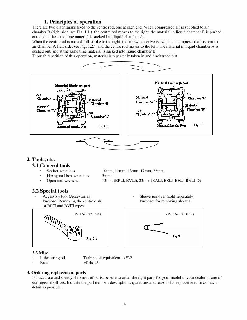
2.2 Special tools � Accessory tool (Accessories)
Purpose: Removing the centre disk
of BP� and BV� types
� Sleeve remover (sold separately)
Purpose: for removing sleeves
Laufbüchsenzieher
2.3 Misc. � Lubricating oil Turbine oil equivalent to #32
� Nuts M14x1.5
3. Ordering replacement parts For accurate and speedy shipment of parts, be sure to order the right parts for your model to your dealer or one of
our regional offices. Indicate the part number, descriptions, quantities and reasons for replacement, in as much
detail as possible.
(Part No. 771244) (Part No. 713148)
5
4. Balls and Valve seats
4.1 Removal
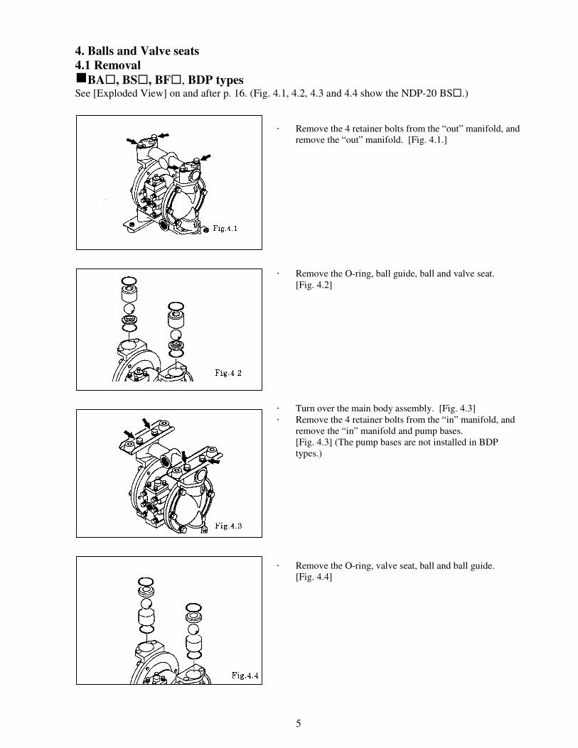
gBA�, BS�, BF�, BDP types See [Exploded View] on and after p. 16. (Fig. 4.1, 4.2, 4.3 and 4.4 show the NDP-20 BS�.)
� Remove the 4 retainer bolts from the “out” manifold, and
remove the “out” manifold. [Fig. 4.1.]
� Remove the O-ring, ball guide, ball and valve seat.
[Fig. 4.2]
� Turn over the main body assembly. [Fig. 4.3]
� Remove the 4 retainer bolts from the “in” manifold, and
remove the “in” manifold and pump bases.
[Fig. 4.3] (The pump bases are not installed in BDP
types.)
� Remove the O-ring, valve seat, ball and ball guide.
[Fig. 4.4]
6
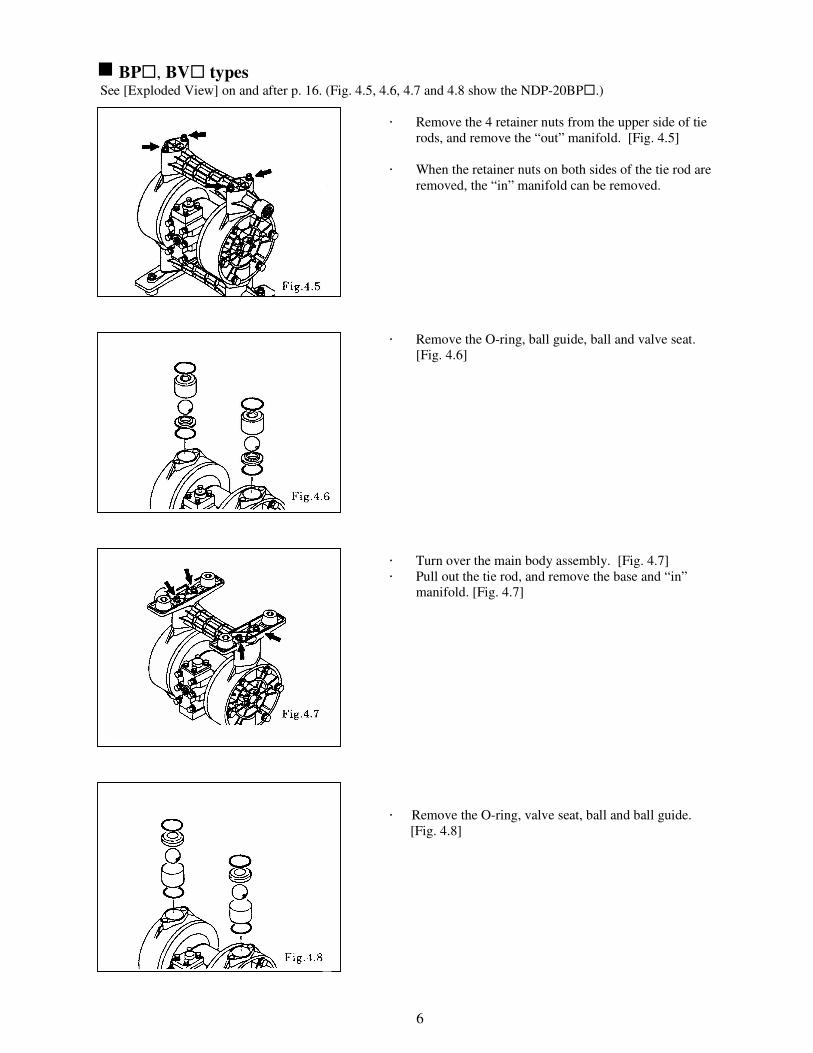
g BP�, BV� types See [Exploded View] on and after p. 16. (Fig. 4.5, 4.6, 4.7 and 4.8 show the NDP-20BP�.)
� Remove the 4 retainer nuts from the upper side of tie
rods, and remove the “out” manifold. [Fig. 4.5]
<NOTE>
� When the retainer nuts on both sides of the tie rod are
removed, the “in” manifold can be removed.
� Remove the O-ring, ball guide, ball and valve seat.
[Fig. 4.6]
� Turn over the main body assembly. [Fig. 4.7]
� Pull out the tie rod, and remove the base and “in”
manifold. [Fig. 4.7]
� Remove the O-ring, valve seat, ball and ball guide.
[Fig. 4.8]
7
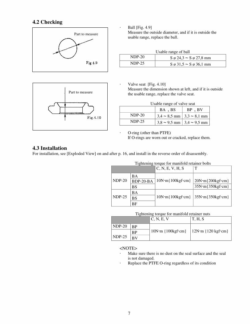
4.2 Checking � Ball [Fig. 4.9]
Measure the outside diameter, and if it is outside the
usable range, replace the ball.
Usable range of ball
NDP-20 S ø 24,3 ~ S ø 27,8 mm
NDP-25 S ø 31,5 ~ S ø 36,1 mm
� Valve seat [Fig. 4.10]
Measure the dimension shown at left, and if it is outside
the usable range, replace the valve seat.
Usable range of valve seat
BA� , BS� BP� , BV�
NDP-20 3,4 ~ 8,5 mm 3,3 ~ 8,1 mm
NDP-25 3,8 ~ 9,5 mm 3,4 ~ 9,5 mm
� O-ring (other than PTFE)
If O-rings are worn out or cracked, replace them.
4.3 Installation For installation, see [Exploded View] on and after p. 16, and install in the reverse order of disassembly.
Tightening torque for manifold retainer bolts
C, N, E, V, H, S T
BA�
BDP-20-BA
20N�m{200kgf�cm}
NDP-20
BS�
10N�m{100kgf�cm}
35N�m{350kgf�cm}
BA�
BS�
NDP-25
BF�
10N�m{100kgf�cm}
35N�m{350kgf�cm}
Tightening torque for manifold retainer nuts
C, N, E, V T, H, S
NDP-20 BP�
BP�
NDP-25 BV�
10N�m {100kgf�cm}
12N�m {120 kgf�cm}
<NOTE> � Make sure there is no dust on the seal surface and the seal
is not damaged.
� Replace the PTFE O-ring regardless of its condition
Part to measure
Part to measure
8
5. Diaphragm and Centre rod
5.1 Removal
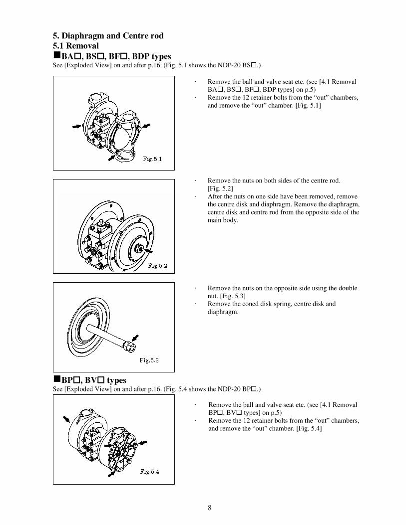
gBA����, BS����, BF����, BDP types See [Exploded View] on and after p.16. (Fig. 5.1 shows the NDP-20 BS�.)
� Remove the ball and valve seat etc. (see [4.1 Removal
BA�, BS�, BF�, BDP types] on p.5)
� Remove the 12 retainer bolts from the “out” chambers,
and remove the “out” chamber. [Fig. 5.1]
� Remove the nuts on both sides of the centre rod.
[Fig. 5.2]
� After the nuts on one side have been removed, remove
the centre disk and diaphragm. Remove the diaphragm,
centre disk and centre rod from the opposite side of the
main body.
� Remove the nuts on the opposite side using the double
nut. [Fig. 5.3]
� Remove the coned disk spring, centre disk and
diaphragm.
gBP����, BV���� types See [Exploded View] on and after p.16. (Fig. 5.4 shows the NDP-20 BP�.)
� Remove the ball and valve seat etc. (see [4.1 Removal
BP�, BV� types] on p.5)
� Remove the 12 retainer bolts from the “out” chambers,
and remove the “out” chamber. [Fig. 5.4]
9
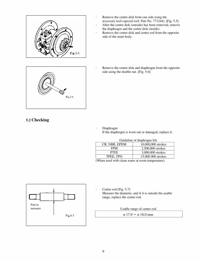
� Remove the centre disk from one side using the
accessory tool (special tool: Part No. 771244). [Fig. 5.5]
� After the centre disk (outside) has been removed, remove
the diaphragm and the centre disk (inside).
� Remove the centre disk and centre rod from the opposite
side of the main body.
� Remove the centre disk and diaphragm from the opposite
side using the double nut. [Fig. 5.6]
5.2 Checking
� Diaphragm
If the diaphragm is worn out or damaged, replace it.
Guideline of diaphragm life
CR, NBR, EPDM 10,000,000 strokes
FPM 2,500,000 strokes
PTFE 3,000,000 strokes
TPEE, TPO 15.000 000 strokes
(When used with clean water at room temperature)
� Centre rod [Fig. 5.7]
Measure the diameter, and if it is outside the usable
range, replace the centre rod.
Usable range of centre rod
ø 17,9 ~ ø 18,0 mm
Part to
measure
10
5.3 Installation
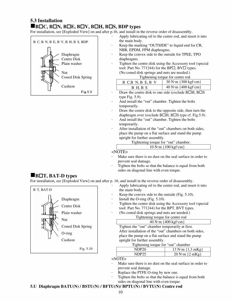
ggggB����C, B����N, B����E, B����V, B����H, B����S, BDP types For installation, see [Exploded View] on and after p.16, and install in the reverse order of disassembly.
� Apply lubricating oil to the centre rod, and insert it into
the main body.
� Keep the marking “OUTSIDE” to liquid end for CR,
NBR, EPDM, FPM diaphragms.
� Keep the convex side to the outside for TPEE, TPO
diaphragms.
� Tighten the centre disk using the Accessory tool (special
tool: Part No. 771244) for the BP�, BV� types.
(No coned disk springs and nuts are needed.)
Tightening torque for centre rod
B� C,B�N, B�E, B�V 30 N�m {300 kgf�cm}
B�H, B�S 40 N�m {400 kgf�cm}
� Draw the centre disk to one side (exclude B�H, B�S
type Fig. 5.9).
� And install the “out” chamber. Tighten the bolts
temporarily.
� Draw the centre disk to the opposite side, then turn the
diaphragm over (exclude B�H, B�S type cf. Fig.5.9).
� And install the “out” chamber. Tighten the bolts
temporarily.
� After installation of the “out” chambers on both sides,
place the pump on a flat surface and stand the pump
upright for further assembly.
Tightening torque for “out” chamber.
10 N�m {100 kgf�cm}
<NOTE> � Make sure there is no dust on the seal surface in order to
prevent seal damage.
� Tighten the bolts so that the balance is equal from both
sides on diagonal line with even torque.
ggggB����T, BAT-D types For installation, see [Exploded View] on and after p. 16, and install in the reverse order of disassembly.
� Apply lubricating oil to the centre rod, and insert it into
the main body
� Keep the convex side to the outside (Fig. 5.10).
� Install the O-ring (Fig. 5.10).
� Tighten the centre disk using the Accessory tool (special
tool: Part No. 771244) for the BPT, BVT types.
� (No coned disk springs and nuts are needed.)
Tightening torque for centre rod
40 N�m {400 kgf�cm}
Tighten the “out” chamber temporarily at first.
After installation of the “out” chambers on both sides,
place the pump on a flat surface and stand the pump
upright for further assembly.
Tightening torque for “out” chamber
NDP20 13 N�m {1,3 mKg}
NDP25 20 N�m {2 mKg}
<NOTE>
� Make sure there is no dust on the seal surface in order to
prevent seal damage.
� Replace the PTFE O-ring by new one. � Tighten the bolts so that the balance is equal from both
sides on diagonal line with even torque.
5.U Diaphragm BATU(N) / BSTU(N) / BFTU(N)/ BPTU(N) / BVTU(N) Centre rod
Diaphragm
Centre Disk
Plain washer
Nut
Coned Disk Spring
Cushion
B�C, B�N, B�E, B�V, B�H, B�S, BDP
Diaphragm
Centre Disk
Plain washer
Nut
Coned Disk Spring
O-ring
Cushion
B�T, BAT-D
Fig. 5.10
11
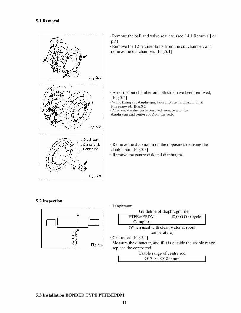
5.1 Removal
· Remove the ball and valve seat etc. (see [ 4.1 Removal] on
p.5)
· Remove the 12 retainer bolts from the out chamber, and
remove the out chamber. [Fig.5.1]
· After the out chamber on both side have been removed,
[Fig.5.2] ···· While fixing one diaphragm, turn another diaphragm until it is removed. [Fig.5.2] ···· After one diaphragm is removed, remove another diaphragm and center rod from the body.
· Remove the diaphragm on the opposite side using the
double nut. [Fig.5.3]
· Remove the centre disk and diaphragm.
5.2 Inspection · Diaphragm
Guideline of diaphragm life
PTFE&EPDM
Complex
40,000,000 cycle
(When used with clean water at room
temperature)
· Centre rod [Fig.5.4]
Measure the diameter, and if it is outside the usable range,
replace the centre rod.
Usable range of centre rod
Ø17.9 ~ Ø18.0 mm
5.3 Installation BONDED TYPE PTFE/EPDM
12
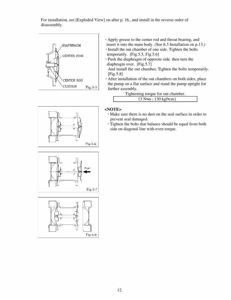
For installation, see [Exploded View] on after p. 16., and install in the reverse order of
disassembly.
· Apply grease to the center rod and throat bearing, and
insert it into the main body. (See 6.3 Installation on p.13.)
· Install the out chamber of one side. Tighten the bolts
temporarily. [Fig.5.5, Fig.5.6]
· Push the diaphragm of opposite side. then turn the
diaphragm over. [Fig.5.7]
And install the out chamber, Tighten the bolts temporarily.
[Fig.5.8]
· After installation of the out chambers on both sides, place
the pump on a flat surface and stand the pump upright for
further assembly.
Tightening torque for out chamber.
13 N•m { 130 kgf•cm}
<NOTE> · Make sure there is no dust on the seal surface in order to
prevent seal damaged.
· Tighten the bolts that balance should be equal from both
side on diagonal line with even torque.
13
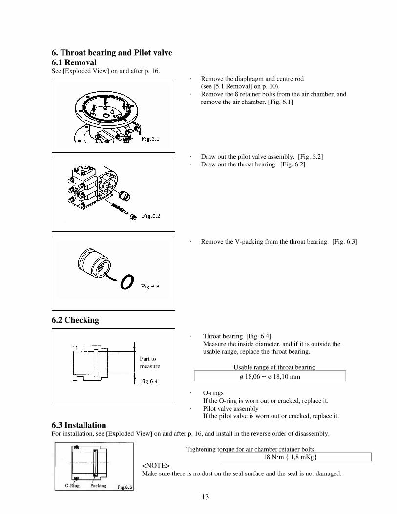
6. Throat bearing and Pilot valve
6.1 Removal See [Exploded View] on and after p. 16.
� Remove the diaphragm and centre rod
(see [5.1 Removal] on p. 10).
� Remove the 8 retainer bolts from the air chamber, and
remove the air chamber. [Fig. 6.1]
� Draw out the pilot valve assembly. [Fig. 6.2]
� Draw out the throat bearing. [Fig. 6.2]
� Remove the V-packing from the throat bearing. [Fig. 6.3]
6.2 Checking
� Throat bearing [Fig. 6.4]
Measure the inside diameter, and if it is outside the
usable range, replace the throat bearing.
Usable range of throat bearing
ø 18,06 ~ ø 18,10 mm
� O-rings
If the O-ring is worn out or cracked, replace it.
� Pilot valve assembly
If the pilot valve is worn out or cracked, replace it.
6.3 Installation For installation, see [Exploded View] on and after p. 16, and install in the reverse order of disassembly.
Tightening torque for air chamber retainer bolts
18 N�m { 1,8 mKg}
<NOTE> Make sure there is no dust on the seal surface and the seal is not damaged.
Part to
measure
14
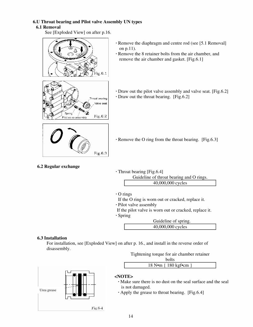
6.U Throat bearing and Pilot valve Assembly UN types 6.1 Removal See [Exploded View] on after p.16.
· Remove the diaphragm and centre rod (see [5.1 Removal]
on p.11).
· Remove the 8 retainer bolts from the air chamber, and
remove the air chamber and gasket. [Fig.6.1]
· Draw out the pilot valve assembly and valve seat. [Fig.6.2]
· Draw out the throat bearing. [Fig.6.2]
· Remove the O ring from the throat bearing. [Fig.6.3]
6.2 Regular exchange · Throat bearing [Fig.6.4]
Guideline of throat bearing and O rings.
40,000,000 cycles
· O rings
If the O ring is worn out or cracked, replace it.
· Pilot valve assembly
If the pilot valve is worn out or cracked, replace it.
· Spring
Guideline of spring.
40,000,000 cycles
6.3 Installation For installation, see [Exploded View] on after p. 16., and install in the reverse order of
disassembly.
Tightening torque for air chamber retainer
bolts
18 N•m { 180 kgf•cm }
<NOTE> · Make sure there is no dust on the seal surface and the seal
is not damaged.
· Apply the grease to throat bearing. [Fig.6.4]
Urea grease

15
7. Seal ring and sleeve
7.1 Removal See [Exploded View] on and after p. 16.
� Remove the 6 retainer bolts from the valve body, and
remove the valve body. [Fig. 7.1]
� Remove the 8 cap A and cap B retainer bolts, and remove
cap A, cap B, packing, plain washer, cushion and gasket.
[Fig. 7.2]
� Draw out the C spool valve assembly, and remove the
seal ring from the C spool valve assembly.
� Remove the sleeve using the sleeve remover (special
tool: Part number 713148). [Fig. 7.3]
7.2 Checking � Seal ring [Fig. 7.4]
Measure the inside thick diameter, and if it is outside the
usable range, replace the seal ring.
If the seal ring is worn out or cracked, replace it.
Usable range of seal ring
2,95 ~ 3.00 mm
� Sleeve [Fig. 7.5]
Measure the inside diameter, and if it is outside the
usable range, replace the sleeve.
Usable range of sleeve
ø 18,45 ~ ø 18,65 mm
� O-rings
If the O-ring is worn out or cracked, replace it.
7.3 Installation For installation see [Exploded View] on and after p.16, and install in the reverse order of disassembly.
Tightening torque for installation cap A, cap B
6 N�m {60 kgf�cm}
Tightening torque for valve body installation bolts
7.5 N�m {75 kgf�cm}
<NOTE>
� Make sure there is no dust on the seal surface and it is not
damaged.
� Install the sleeve at the centre of the valve body. At this
point, apply lubricating oil around the sleeve and O-ring.
Part to measure
Part to measure
16
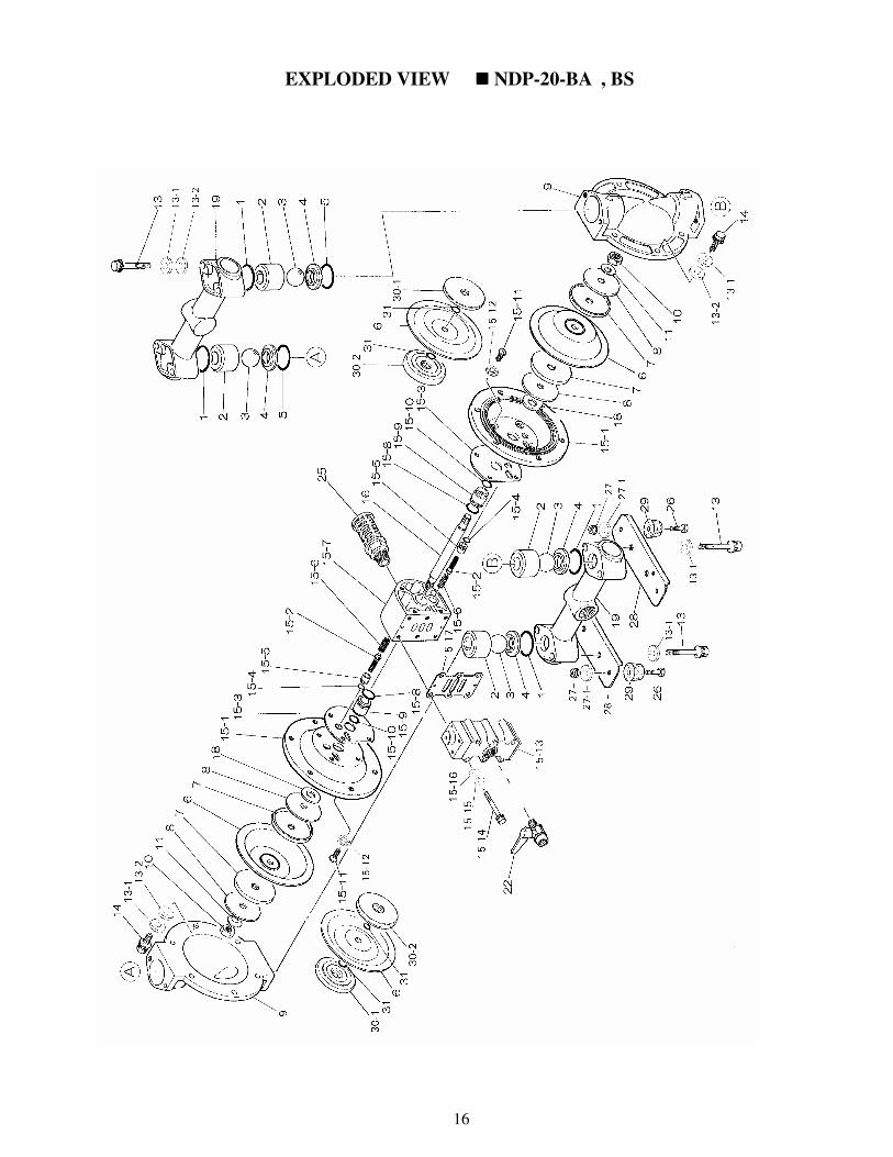
EXPLODED VIEW ���� NDP-20-BA���� , BS����
17
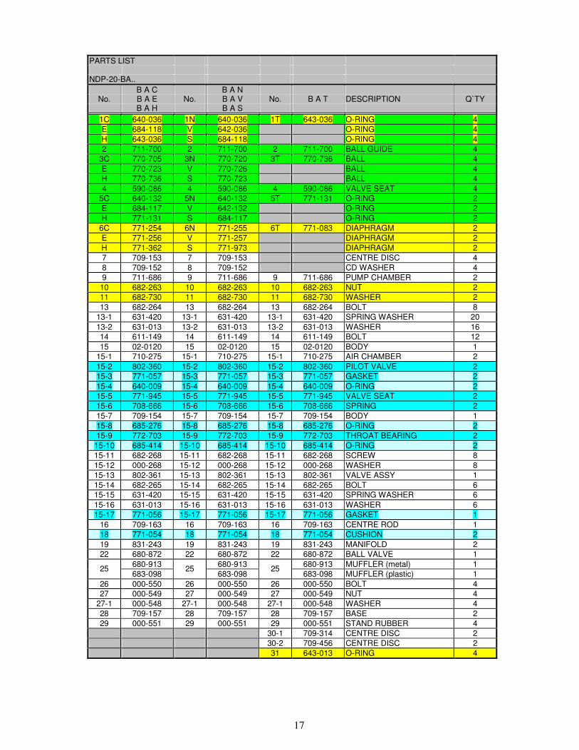
PARTS LIST NDP-20-BA..
B A C B A N No. B A E No. B A V No. B A T DESCRIPTION Q`TY
B A H B A S
1C 640-036 1N 640-036 1T 643-036 O-RING 4
E 684-118 V 642-036 O-RING 4
H 643-036 S 684-118 O-RING 4
2 711-700 2 711-700 2 711-700 BALL GUIDE 4
3C 770-705 3N 770-720 3T 770-736 BALL 4
E 770-723 V 770-726 BALL 4
H 770-736 S 770-723 BALL 4
4 590-086 4 590-086 4 590-086 VALVE SEAT 4
5C 640-132 5N 640-132 5T 771-131 O-RING 2
E 684-117 V 642-132 O-RING 2
H 771-131 S 684-117 O-RING 2
6C 771-254 6N 771-255 6T 771-083 DIAPHRAGM 2
E 771-256 V 771-257 DIAPHRAGM 2
H 771-362 S 771-973 DIAPHRAGM 2
7 709-153 7 709-153 CENTRE DISC 4
8 709-152 8 709-152 CD WASHER 4
9 711-686 9 711-686 9 711-686 PUMP CHAMBER 2
10 682-263 10 682-263 10 682-263 NUT 2
11 682-730 11 682-730 11 682-730 WASHER 2
13 682-264 13 682-264 13 682-264 BOLT 8
13-1 631-420 13-1 631-420 13-1 631-420 SPRING WASHER 20
13-2 631-013 13-2 631-013 13-2 631-013 WASHER 16
14 611-149 14 611-149 14 611-149 BOLT 12
15 02-0120 15 02-0120 15 02-0120 BODY 1
15-1 710-275 15-1 710-275 15-1 710-275 AIR CHAMBER 2
15-2 802-360 15-2 802-360 15-2 802-360 PILOT VALVE 2
15-3 771-057 15-3 771-057 15-3 771-057 GASKET 2
15-4 640-009 15-4 640-009 15-4 640-009 O-RING 2
15-5 771-945 15-5 771-945 15-5 771-945 VALVE SEAT 2
15-6 708-666 15-6 708-666 15-6 708-666 SPRING 2
15-7 709-154 15-7 709-154 15-7 709-154 BODY 1
15-8 685-276 15-8 685-276 15-8 685-276 O-RING 2
15-9 772-703 15-9 772-703 15-9 772-703 THROAT BEARING 2
15-10 685-414 15-10 685-414 15-10 685-414 O-RING 2
15-11 682-268 15-11 682-268 15-11 682-268 SCREW 8
15-12 000-268 15-12 000-268 15-12 000-268 WASHER 8
15-13 802-361 15-13 802-361 15-13 802-361 VALVE ASSY 1
15-14 682-265 15-14 682-265 15-14 682-265 BOLT 6
15-15 631-420 15-15 631-420 15-15 631-420 SPRING WASHER 6
15-16 631-013 15-16 631-013 15-16 631-013 WASHER 6
15-17 771-056 15-17 771-056 15-17 771-056 GASKET 1
16 709-163 16 709-163 16 709-163 CENTRE ROD 1
18 771-054 18 771-054 18 771-054 CUSHION 2
19 831-243 19 831-243 19 831-243 MANIFOLD 2
22 680-872 22 680-872 22 680-872 BALL VALVE 1
680-913 680-913 680-913 MUFFLER (metal) 1 25
683-098 25
683-098 25
683-098 MUFFLER (plastic) 1
26 000-550 26 000-550 26 000-550 BOLT 4
27 000-549 27 000-549 27 000-549 NUT 4
27-1 000-548 27-1 000-548 27-1 000-548 WASHER 4
28 709-157 28 709-157 28 709-157 BASE 2
29 000-551 29 000-551 29 000-551 STAND RUBBER 4
30-1 709-314 CENTRE DISC 2
30-2 709-456 CENTRE DISC 2
31 643-013 O-RING 4

18
PARTS LIST NDP-20-BS..
B S C B S N No. B S E No. B S V No. B S T DESCRIPTION Q`TY
B S H B S S
1C 640-036 1N 640-036 1T 643-036 O-RING 4
E 684-118 V 642-036 O-RING 4
H 643-036 S 684-118 O-RING 4
2 711-701 2 711-701 2 711-701 BALL GUIDE 4
3C 770-705 3N 770-720 3T 770-736 BALL 4
E 770-723 V 770-726 BALL 4
H 770-736 S 770-723 BALL 4
4 711-705 4 711-705 4 711-705 VALVE SEAT 4
5C 640-132 5N 640-132 5T 771-131 O-RING 2
E 684-117 V 642-132 O-RING 2
H 771-131 S 684-117 O-RING 2
6C 771-254 6N 771-255 6T 771-083 DIAPHRAGM 2
E 771-256 V 771-257 DIAPHRAGM 2
H 771-362 S 771-973 DIAPHRAGM 2
7 709-153 7 709-153 CENTRE DISC 4
8 709-152 8 709-152 CD WASHER 4
9 711-693 9 711-693 9 711-693 PUMP CHAMBER 2
10 682-263 10 682-263 10 682-263 NUT 2
11 682-730 11 682-730 11 682-730 WASHER 2
13 621-159 13 621-159 13 621-159 BOLT 8
13-1 681-300 13-1 681-300 13-1 681-300 SPRING WASHER 20
13-2 631-329 13-2 631-329 13-2 631-329 WASHER 16
14 621-149 14 621-149 14 621-149 BOLT 12
15 02-0120 15 02-0120 15 02-0120 BODY 1
15-1 710-275 15-1 710-275 15-1 710-275 AIR CHAMBER 2
15-2 802-360 15-2 802-360 15-2 802-360 PILOT VALVE 2
15-3 771-057 15-3 771-057 15-3 771-057 GASKET 2
15-4 640-009 15-4 640-009 15-4 640-009 O-RING 2
15-5 771-945 15-5 771-945 15-5 771-945 VALVE SEAT 2
15-6 708-666 15-6 708-666 15-6 708-666 SPRING 2
15-7 709-154 15-7 709-154 15-7 709-154 BODY 1
15-8 685-276 15-8 685-276 15-8 685-276 O-RING 2
15-9 772-703 15-9 772-703 15-9 772-703 THROAT BEARING 2
15-10 685-414 15-10 685-414 15-10 685-414 O-RING 2
15-11 682-268 15-11 682-268 15-11 682-268 SCREW 8
15-12 000-268 15-12 000-268 15-12 000-268 WASHER 8
15-13 802-361 15-13 802-361 15-13 802-361 VALVE ASSY 1
15-14 682-265 15-14 682-265 15-14 682-265 BOLT 6
15-15 631-420 15-15 631-420 15-15 631-420 SPRING WASHER 6
15-16 631-013 15-16 631-013 15-16 631-013 WASHER 6
15-17 771-056 15-17 771-056 15-17 771-056 GASKET 1
16 709-163 16 709-163 16 709-163 CENTRE ROD 1
18 771-054 18 771-054 18 771-054 CUSHION 2
19 831-245 19 831-245 19 831-245 MANIFOLD 2
22 680-872 22 680-872 22 680-872 BALL VALVE 1
680-913 680-913 680-913 MUFFLER (metal) 1 25
683-098 25
683-098 25
683-098 MUFFLER (plastic) 1
26 000-550 26 000-550 26 000-550 BOLT 4
27 000-549 27 000-549 27 000-549 NUT 4
27-1 000-548 27-1 000-548 27-1 000-548 WASHER 4
28 709-157 28 709-157 28 709-157 BASE 2
29 000-551 29 000-551 29 000-551 STAND RUBBER 4
30-1 709-326 CENTRE DISC 2
30-2 709-456 CENTRE DISC 2
31 643-013 O-RING 4

19
EXPLODED VIEW ���� NDP-20-BATU(N)/BSTU(N)
20
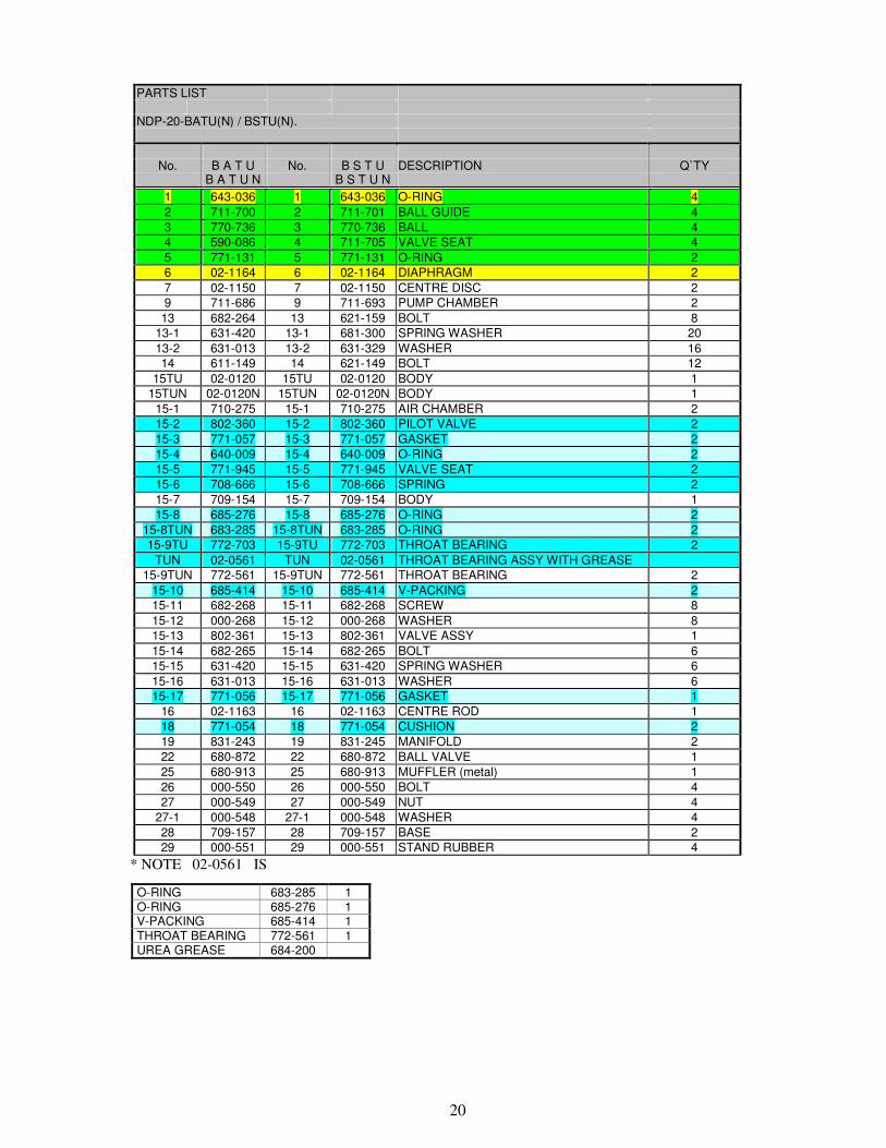
PARTS LIST NDP-20-BATU(N) / BSTU(N).
No. B A T U No. B S T U DESCRIPTION Q`TY
B A T U N B S T U N
1 643-036 1 643-036 O-RING 4
2 711-700 2 711-701 BALL GUIDE 4
3 770-736 3 770-736 BALL 4
4 590-086 4 711-705 VALVE SEAT 4
5 771-131 5 771-131 O-RING 2
6 02-1164 6 02-1164 DIAPHRAGM 2
7 02-1150 7 02-1150 CENTRE DISC 2
9 711-686 9 711-693 PUMP CHAMBER 2
13 682-264 13 621-159 BOLT 8
13-1 631-420 13-1 681-300 SPRING WASHER 20
13-2 631-013 13-2 631-329 WASHER 16
14 611-149 14 621-149 BOLT 12
15TU 02-0120 15TU 02-0120 BODY 1
15TUN 02-0120N 15TUN 02-0120N BODY 1
15-1 710-275 15-1 710-275 AIR CHAMBER 2
15-2 802-360 15-2 802-360 PILOT VALVE 2
15-3 771-057 15-3 771-057 GASKET 2
15-4 640-009 15-4 640-009 O-RING 2
15-5 771-945 15-5 771-945 VALVE SEAT 2
15-6 708-666 15-6 708-666 SPRING 2
15-7 709-154 15-7 709-154 BODY 1
15-8 685-276 15-8 685-276 O-RING 2
15-8TUN 683-285 15-8TUN 683-285 O-RING 2
15-9TU 772-703 15-9TU 772-703 THROAT BEARING 2
TUN 02-0561 TUN 02-0561 THROAT BEARING ASSY WITH GREASE
15-9TUN 772-561 15-9TUN 772-561 THROAT BEARING 2
15-10 685-414 15-10 685-414 V-PACKING 2
15-11 682-268 15-11 682-268 SCREW 8
15-12 000-268 15-12 000-268 WASHER 8
15-13 802-361 15-13 802-361 VALVE ASSY 1
15-14 682-265 15-14 682-265 BOLT 6
15-15 631-420 15-15 631-420 SPRING WASHER 6
15-16 631-013 15-16 631-013 WASHER 6
15-17 771-056 15-17 771-056 GASKET 1
16 02-1163 16 02-1163 CENTRE ROD 1
18 771-054 18 771-054 CUSHION 2
19 831-243 19 831-245 MANIFOLD 2
22 680-872 22 680-872 BALL VALVE 1
25 680-913 25 680-913 MUFFLER (metal) 1
26 000-550 26 000-550 BOLT 4
27 000-549 27 000-549 NUT 4
27-1 000-548 27-1 000-548 WASHER 4
28 709-157 28 709-157 BASE 2
29 000-551 29 000-551 STAND RUBBER 4
* NOTE 02-0561 IS
O-RING 683-285 1 O-RING 685-276 1 V-PACKING 685-414 1 THROAT BEARING 772-561 1 UREA GREASE 684-200

21
EXPLODED VIEW ���� NDP-20-BP����
22
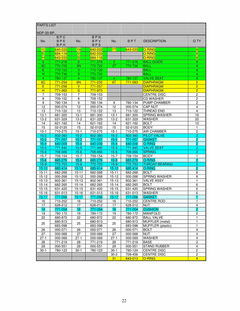
PARTS LIST
NDP-20-BP..
B P C B P N No. B P E No. B P V No. B P T DESCRIPTION Q`TY
B P H B P S
1C 640-033 1N 640-033 1T 643-033 O-RING 8
E 684-116 V 642-033 O-RING 8
H 643-033 S 684-116 O-RING 8
2 771-216 2 771-216 2 771-216 BALL GUIDE 4
3C 770-705 3N 770-720 3T 770-736 BALL 4
E 770-723 V 770-726 BALL 4
H 770-736 S 770-723 BALL 4
4 780-137 4 780-137 4 780-137 VALVE SEAT 4
6C 771-254 6N 771-255 6T 771-083 DIAPHRAGM 2
E 771-256 V 771-257 DIAPHRAGM 2
H 771-362 S 771-973 DIAPHRAGM 2
7 709-153 7 709-153 CENTRE DISC 2
8 709-152 8 709-152 CD WASHER 2
9 780-134 9 780-134 9 780-134 PUMP CHAMBER 2
12 000-074 12 000-074 12 000-074 CAP NUT 4
13 710-122 13 710-122 13 710-122 THREAD END 4
13-1 681-300 13-1 681-300 13-1 681-300 SPRING WASHER 16
13-2 631-329 13-2 631-329 13-2 631-329 WASHER 20
14 621-162 14 621-162 14 621-162 BOLT 12
15 02-0120 15 02-0120 15 02-0120 BODY 1
15-1 710-275 15-1 710-275 15-1 710-275 AIR CHAMBER 2
15-2 802-360 15-2 802-360 15-2 802-360 PILOT VALVE 2
15-3 771-057 15-3 771-057 15-3 771-057 GASKET 2
15-4 640-009 15-4 640-009 15-4 640-009 O-RING 2
15-5 771-945 15-5 771-945 15-5 771-945 VALVE SEAT 2
15-6 708-666 15-6 708-666 15-6 708-666 SPRING 2
15-7 709-154 15-7 709-154 15-7 709-154 BODY 1
15-8 685-276 15-8 685-276 15-8 685-276 O-RING 2
15-9 772-703 15-9 772-703 15-9 772-703 THROAT BEARING 2
15-10 685-414 15-10 685-414 15-10 685-414 O-RING 2
15-11 682-268 15-11 682-268 15-11 682-268 BOLT 8
15-12 000-268 15-12 000-268 15-12 000-268 SPRING WASHER 8
15-13 802-361 15-13 802-361 15-13 802-361 VALVE ASSY 1
15-14 682-265 15-14 682-265 15-14 682-265 BOLT 6
15-15 631-420 15-15 631-420 15-15 631-420 SPRING WASHER 6
15-16 631-013 15-16 631-013 15-16 631-013 WASHER 6
15-17 771-056 15-17 771-056 15-17 771-056 GASKET 1
16 710-252 16 710-252 16 710-252 CENTRE ROD 1
17 628-012 17 628-012 17 628-012 NUT 4
18 771-054 18 771-054 18 771-054 CUSHION 2
19 780-172 19 780-172 19 780-172 MANIFOLD 2
22 680-872 22 680-872 22 680-872 BALL VALVE 1
680-913 680-913 680-913 MUFFLER (metal) 1 25
683-098 25
683-098 25
683-098 MUFFLER (plastic) 1
26 000-071 26 000-071 26 000-071 BOLT 4
27 000-068 27 000-068 27 000-068 NUT 4
27-1 000-069 27-1 000-069 27-1 000-069 WASHER 4
28 771-219 28 771-219 28 771-219 BASE 2
29 000-551 29 000-551 29 000-551 STAND RUBBER 4
30-1 780-123 30-1 780-123 30-1 780-124 CENTRE DISC 2
30-2 709-456 CENTRE DISC 2
31 643-013 O-RING 4
23
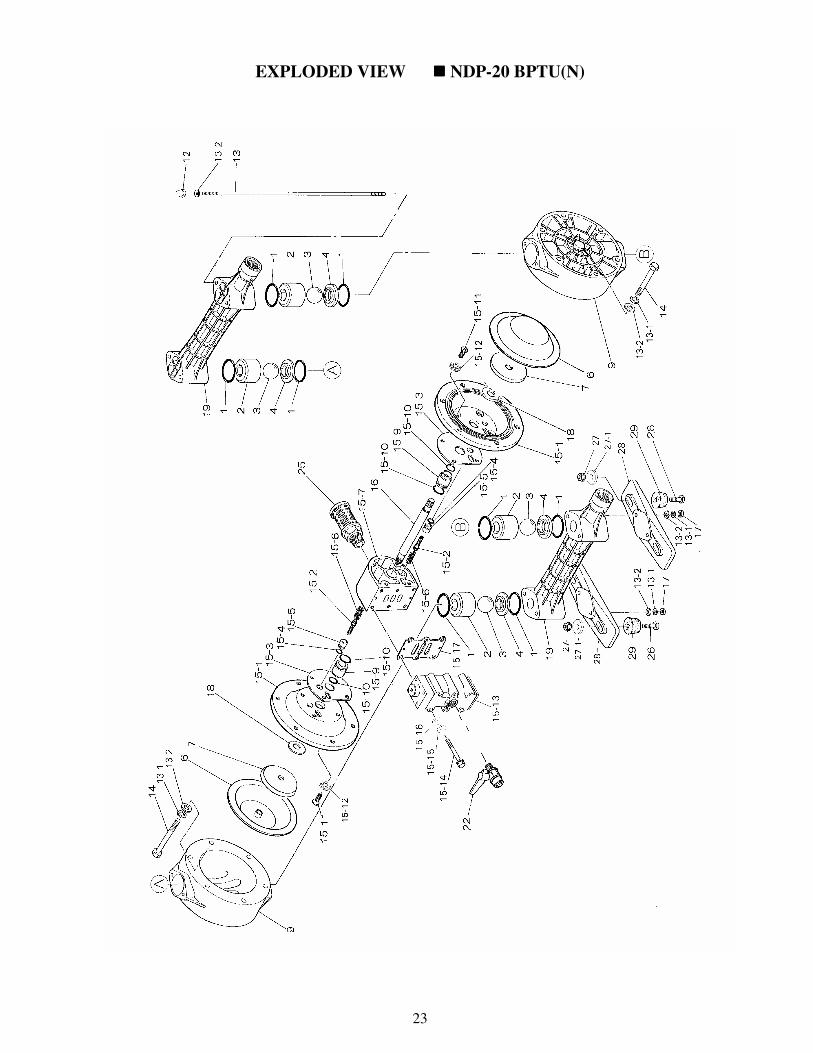
EXPLODED VIEW ���� NDP-20 BPTU(N)
24
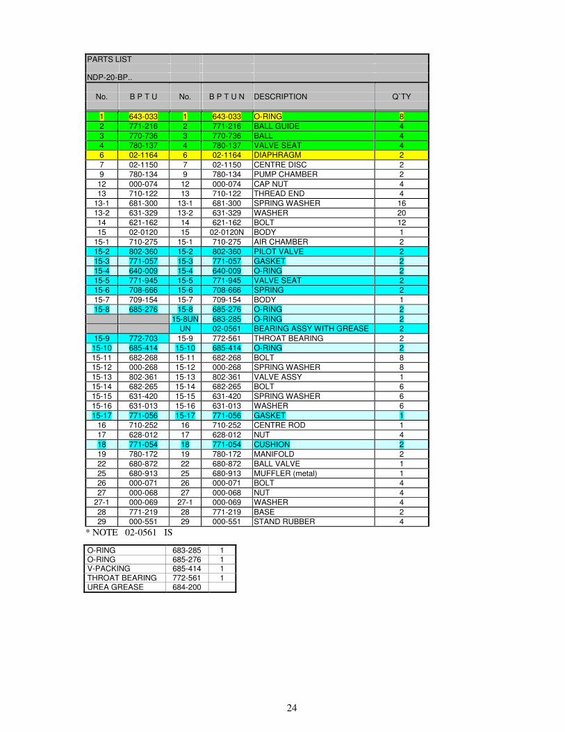
PARTS LIST
NDP-20-BP..
No. B P T U No. B P T U N DESCRIPTION Q`TY
1 643-033 1 643-033 O-RING 8
2 771-216 2 771-216 BALL GUIDE 4
3 770-736 3 770-736 BALL 4
4 780-137 4 780-137 VALVE SEAT 4
6 02-1164 6 02-1164 DIAPHRAGM 2
7 02-1150 7 02-1150 CENTRE DISC 2
9 780-134 9 780-134 PUMP CHAMBER 2
12 000-074 12 000-074 CAP NUT 4
13 710-122 13 710-122 THREAD END 4
13-1 681-300 13-1 681-300 SPRING WASHER 16
13-2 631-329 13-2 631-329 WASHER 20
14 621-162 14 621-162 BOLT 12
15 02-0120 15 02-0120N BODY 1
15-1 710-275 15-1 710-275 AIR CHAMBER 2
15-2 802-360 15-2 802-360 PILOT VALVE 2
15-3 771-057 15-3 771-057 GASKET 2
15-4 640-009 15-4 640-009 O-RING 2
15-5 771-945 15-5 771-945 VALVE SEAT 2
15-6 708-666 15-6 708-666 SPRING 2
15-7 709-154 15-7 709-154 BODY 1
15-8 685-276 15-8 685-276 O-RING 2
15-8UN 683-285 O-RING 2
UN 02-0561 BEARING ASSY WITH GREASE 2
15-9 772-703 15-9 772-561 THROAT BEARING 2
15-10 685-414 15-10 685-414 O-RING 2
15-11 682-268 15-11 682-268 BOLT 8
15-12 000-268 15-12 000-268 SPRING WASHER 8
15-13 802-361 15-13 802-361 VALVE ASSY 1
15-14 682-265 15-14 682-265 BOLT 6
15-15 631-420 15-15 631-420 SPRING WASHER 6
15-16 631-013 15-16 631-013 WASHER 6
15-17 771-056 15-17 771-056 GASKET 1
16 710-252 16 710-252 CENTRE ROD 1
17 628-012 17 628-012 NUT 4
18 771-054 18 771-054 CUSHION 2
19 780-172 19 780-172 MANIFOLD 2
22 680-872 22 680-872 BALL VALVE 1
25 680-913 25 680-913 MUFFLER (metal) 1
26 000-071 26 000-071 BOLT 4
27 000-068 27 000-068 NUT 4
27-1 000-069 27-1 000-069 WASHER 4
28 771-219 28 771-219 BASE 2
29 000-551 29 000-551 STAND RUBBER 4
* NOTE 02-0561 IS
O-RING 683-285 1 O-RING 685-276 1 V-PACKING 685-414 1 THROAT BEARING 772-561 1 UREA GREASE 684-200
25
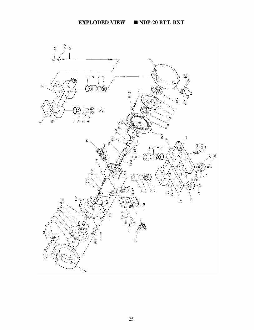
EXPLODED VIEW ���� NDP-20 BTT, BXT
26
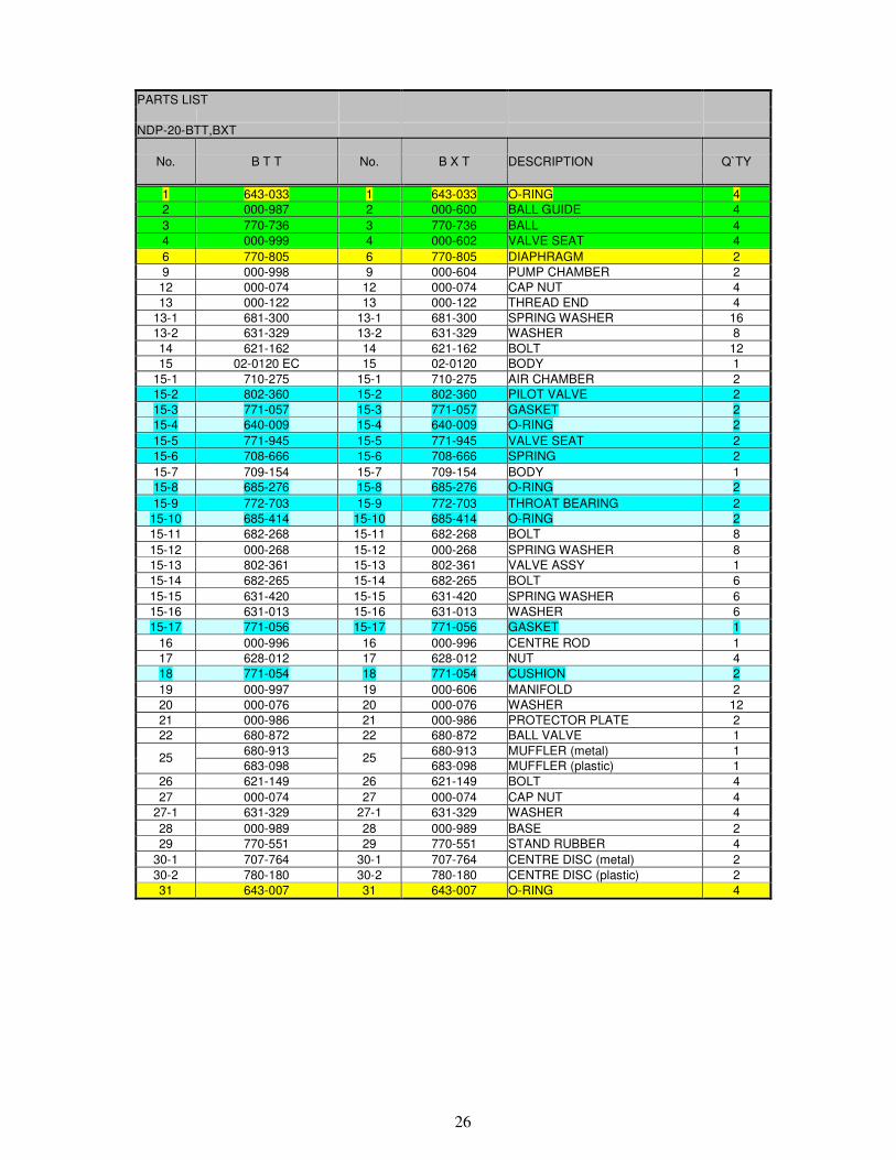
PARTS LIST
NDP-20-BTT,BXT
No. B T T No. B X T DESCRIPTION Q`TY
1 643-033 1 643-033 O-RING 4
2 000-987 2 000-600 BALL GUIDE 4
3 770-736 3 770-736 BALL 4
4 000-999 4 000-602 VALVE SEAT 4
6 770-805 6 770-805 DIAPHRAGM 2
9 000-998 9 000-604 PUMP CHAMBER 2
12 000-074 12 000-074 CAP NUT 4
13 000-122 13 000-122 THREAD END 4
13-1 681-300 13-1 681-300 SPRING WASHER 16
13-2 631-329 13-2 631-329 WASHER 8
14 621-162 14 621-162 BOLT 12
15 02-0120 EC 15 02-0120 BODY 1
15-1 710-275 15-1 710-275 AIR CHAMBER 2
15-2 802-360 15-2 802-360 PILOT VALVE 2
15-3 771-057 15-3 771-057 GASKET 2
15-4 640-009 15-4 640-009 O-RING 2
15-5 771-945 15-5 771-945 VALVE SEAT 2
15-6 708-666 15-6 708-666 SPRING 2
15-7 709-154 15-7 709-154 BODY 1
15-8 685-276 15-8 685-276 O-RING 2
15-9 772-703 15-9 772-703 THROAT BEARING 2
15-10 685-414 15-10 685-414 O-RING 2
15-11 682-268 15-11 682-268 BOLT 8
15-12 000-268 15-12 000-268 SPRING WASHER 8
15-13 802-361 15-13 802-361 VALVE ASSY 1
15-14 682-265 15-14 682-265 BOLT 6
15-15 631-420 15-15 631-420 SPRING WASHER 6
15-16 631-013 15-16 631-013 WASHER 6
15-17 771-056 15-17 771-056 GASKET 1
16 000-996 16 000-996 CENTRE ROD 1
17 628-012 17 628-012 NUT 4
18 771-054 18 771-054 CUSHION 2
19 000-997 19 000-606 MANIFOLD 2
20 000-076 20 000-076 WASHER 12
21 000-986 21 000-986 PROTECTOR PLATE 2
22 680-872 22 680-872 BALL VALVE 1
680-913 680-913 MUFFLER (metal) 1 25
683-098 25
683-098 MUFFLER (plastic) 1
26 621-149 26 621-149 BOLT 4
27 000-074 27 000-074 CAP NUT 4
27-1 631-329 27-1 631-329 WASHER 4
28 000-989 28 000-989 BASE 2
29 770-551 29 770-551 STAND RUBBER 4
30-1 707-764 30-1 707-764 CENTRE DISC (metal) 2
30-2 780-180 30-2 780-180 CENTRE DISC (plastic) 2
31 643-007 31 643-007 O-RING 4
27
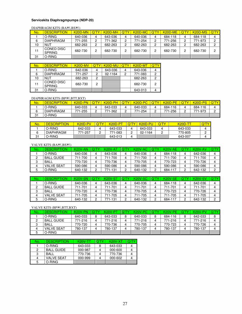
Servicekits Diaphragmpumps (NDP-20) DIAPHRAGM KITS (BA�,BS�)
No. DESCRIPTION K20D-MN Q’TY K20D-MH Q’TY K20D-MC Q’TY K20D-ME Q’TY K20D-MS Q’TY
1 O-RING 640-036 4 643-036 4 640-036 4 684-118 4 684-118 4 6 DIAPHRAGM 771-255 2 771-362 2 771-254 2 771-256 2 771-973 2
10 NUT 682-263 2 682-263 2 682-263 2 682-263 2 682-263 2
11 CONED DISC SPRING
682-730 2 682-730 2 682-730 2 682-730 2 682-730 2
31 O-RING
No. DESCRIPTION K20D-MV Q’TY K20D-MU Q’TY K20D-MT Q’TY
1 O-RING 642-036 4 643-036 4 643-036 4 6 DIAPHRAGM 771-257 2 02-1164 2 771-083 2
10 NUT 682-263 2 682-263 2
11 CONED DISC SPRING
682-730 2
682-730 2
31 O-RING 643-013 4
DIAPHRAGM KITS (BP�,BTT,BXT)
No. DESCRIPTION K20D-PN Q’TY K20D-PH Q’TY K20D-PC Q’TY K20D-PE Q’TY K20D-PS Q’TY
1 O-RING 640-033 4 643-033 4 640-033 4 684-116 4 684-116 4 6 DIAPHRAGM 771-255 2 771-362 2 771-254 2 771-256 2 771-973 2
31 O-RING
No. DESCRIPTION K20D-PV Q’TY K20D-PT Q’TY K20D-PU Q’TY K20D-TT Q’TY
1 O-RING 642-033 4 643-033 4 643-033 4 643-033 4 6 DIAPHRAGM 771-257 2 771-083 2 02-1164 2 770-805 2 31 O-RING 643-013 4 643-007 4
VALVE KITS (BA�,BS�)
No. DESCRIPTION K20V-AN Q’TY K20V-AT Q’TY K20V-AC Q’TY K20V-AE Q’TY K20V-AV Q’TY
1 O-RING 640-036 4 643-036 4 640-036 4 684-118 4 642-036 4 2 BALL GUIDE 711-700 4 711-700 4 711-700 4 711-700 4 711-700 4 3 BALL 770-720 4 770-736 4 770-705 4 770-723 4 770-726 4 4 VALVE SEAT 590-086 4 590-086 4 590-086 4 590-086 4 590-086 4 5 O-RING 640-132 2 771-131 2 640-132 2 684-117 2 642-132 2
No. DESCRIPTION K20V-SN Q’TY K20V-ST Q’TY K20V-SC Q’TY K20V-SE Q’TY K20V-SV Q’TY
1 O-RING 640-036 4 643-036 4 640-036 4 684-118 4 642-036 4 2 BALL GUIDE 711-701 4 711-701 4 711-701 4 711-701 4 711-701 4 3 BALL 770-720 4 770-736 4 770-705 4 770-723 4 770-726 4
4 VALVE SEAT 711-705 4 711-705 4 711-705 4 711-705 4 711-705 4 5 O-RING 640-132 2 771-131 2 640-132 2 684-117 2 642-132 2
VALVE KITS (BP�,BTT,BXT)
No. DESCRIPTION K20V-PN Q’TY K20V-PT Q’TY K20V-PC Q’TY K20V-PE Q’TY K20V-PV Q’TY
1 O-RING 640-033 8 643-033 8 640-033 8 684-116 8 642-033 8 2 BALL GUIDE 771-216 4 771-216 4 771-216 4 771-216 4 771-216 4 3 BALL 770-720 4 770-736 4 770-705 4 770-723 4 770-726 4 4 VALVE SEAT 780-137 4 780-137 4 780-137 4 780-137 4 780-137 4 5 O-RING
No. DESCRIPTION K20V-TT Q’TY K20V-XT Q’TY
1 O-RING 643-033 8 643-033 4 2 BALL GUIDE 000-987 4 000-600 4 3 BALL 770-736 4 770-736 4 4 VALVE SEAT 000-999 4 000-602 4 5 O-RING
28
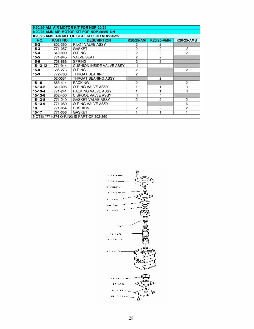
K20/25-AM AIR MOTOR KIT FOR NDP-20/25
K20/25-AMN AIR MOTOR KIT FOR NDP-20/25 UN K20/25-AMS AIR MOTOR SEAL KIT FOR NDP-20/25
NO. PART NO. DESCRIPTION K20/25-AM K20/25-AMN K20/25-AMS 15-2 802-360 PILOT VALVE ASSY 2 2 15-3 771-057 GASKET 2 2 2 15-4 640-009 O-RING 2 2 2 15-5 771-945 VALVE SEAT 2 2
15-6 708-666 SPRING 2 2 15-13-12 771-914 CUSHION INSIDE VALVE ASSY 1 1 15-8 685-276 O-RING 2 2 15-9 772-703 THROAT BEARING 2 02-0561 THROAT BEARING ASSY 2
15-10 685-414 PACKING 2 2 15-13-2 640-005 O-RING VALVE ASSY 1 1 1
15-13-4 771-241 PACKING VALVE ASSY 1 1 1 15-13-6 802-400 C SPOOL VALVE ASSY 1 1 15-13-8 771-240 GASKET VALVE ASSY 2 2 2 15-13-9 771-080 O-RING VALVE ASSY 6 18 771-054 CUSHION 2 2 2
15-17 771-056 GASKET 1 1 1 NOTE) *771-374 O-RING IS PART OF 802-360
29
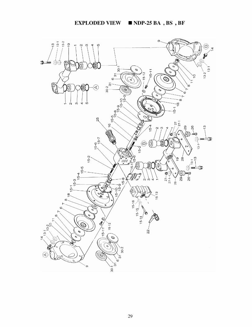
EXPLODED VIEW ���� NDP-25 BA���� , BS���� , BF����

30
PARTS LIST
NDP-25-BA..
B A C B A N No. B A E No. B A V No. B A T DESCRIPTION Q`TY
B A H B A S
1C 640-044 1N 640-044 1T 643-044 O-RING 4
E 683-997 V 642-044 O-RING 4
H 643-044 S 683-997 O-RING 4
2 711-702 2 711-702 2 711-702 BALL GUIDE 4
3C 770-556 3N 770-581 3T 770-691 BALL 4
E 770-590 V 770-599 BALL 4
H 770-691 S 770-590 BALL 4
4 590-087 4 590-087 4 590-087 VALVE SEAT 4
5C 640-134 5N 640-134 5T 771-130 O-RING 2
E 683-996 V 642-134 O-RING 2
H 771-130 S 683-996 O-RING 2
6C 771-258 6N 771-259 6T 771-110 DIAPHRAGM 2
E 771-260 V 771-261 DIAPHRAGM 2
H 771-363 S 771-974 DIAPHRAGM 2
7 709-151 7 709-151 CENTRE DISC 4
8 709-150 8 709-150 CD WASHER 4
9 711-687 9 711-687 9 711-687 PUMP CHAMBER 2
10 682-263 10 682-263 10 682-263 NUT 2
11 682-730 11 682-730 11 682-730 WASHER 2
13 682-267 13 682-267 13 682-267 BOLT 8
13-1 631-421 13-1 631-421 13-1 631-421 SPRING WASHER 20
13-2 631-210 13-2 631-210 13-2 631-210 WASHER 16
14 611-175 14 611-175 14 611-175 BOLT 12
15 02-0125 15 02-0125 15 02-0125 BODY 1
15-1 710-276 15-1 710-276 15-1 710-276 AIR CHAMBER 2
15-2 802-360 15-2 802-360 15-2 802-360 PILOT VALVE 2
15-3 771-057 15-3 771-057 15-3 771-057 GASKET 2
15-4 640-009 15-4 640-009 15-4 640-009 O-RING 2
15-5 771-945 15-5 771-945 15-5 771-945 VALVE SEAT 2
15-6 708-666 15-6 708-666 15-6 708-666 SPRING 2
15-7 709-154 15-7 709-154 15-7 709-154 BODY 1
15-8 685-276 15-8 685-276 15-8 685-276 O-RING 2
15-9 772-703 15-9 772-703 15-9 772-703 THROAT BEARING 2
15-10 685-414 15-10 685-414 15-10 685-414 O-RING 2
15-11 682-268 15-11 682-268 15-11 682-268 SCREW 8
15-12 000-268 15-12 000-268 15-12 000-268 WASHER 8
15-13 802-361 15-13 802-361 15-13 802-361 VALVE ASSY 1
15-14 682-265 15-14 682-265 15-14 682-265 BOLT 6
15-15 631-420 15-15 631-420 15-15 631-420 SPRING WASHER 6
15-16 631-013 15-16 631-013 15-16 631-013 WASHER 6
15-17 771-056 15-17 771-056 15-17 771-056 GASKET 1
16 709-162 16 709-162 16 709-162 CENTRE ROD 1
18 771-054 18 771-054 18 771-054 CUSHION 2
19 831-244 19 831-244 19 831-244 MANIFOLD 2
22 680-872 22 680-872 22 680-872 BALL VALVE 1
680-913 680-913 680-913 MUFFLER (metal) 1 25
683-098 25
683-098 25
683-098 MUFFLER (plastic) 1
26 000-550 26 000-550 26 000-550 BOLT 4
27 000-549 27 000-549 27 000-549 NUT 4
27-1 000-548 27-1 000-548 27-1 000-548 WASHER 4
28 709-156 28 709-156 28 709-156 BASE 2
29 000-551 29 000-551 29 000-551 STAND RUBBER 4
30-1 709-327 CENTRE DISC 2
30-2 709-459 CENTRE DISC 2
31 643-013 O-RING 4

31
PARTS LIST
NDP-25-BS..
B S C B S N No. B S E No. B S V No. B S T DESCRIPTION Q`TY
B S H B S S
1C 640-044 1N 640-044 1T 643-044 O-RING 4
E 683-997 V 642-044 O-RING 4
H 643-044 S 683-997 O-RING 4
2 711-703 2 711-703 2 711-703 BALL GUIDE 4
3C 770-556 3N 770-581 3T 770-691 BALL 4
E 770-590 V 770-599 BALL 4
H 770-691 S 770-590 BALL 4
4 711-707 4 711-707 4 711-707 VALVE SEAT 4
5C 640-134 5N 640-134 5T 771-130 O-RING 2
E 683-996 V 642-134 O-RING 2
H 771-130 S 683-996 O-RING 2
6C 771-258 6N 771-259 6T 771-110 DIAPHRAGM 2
E 771-260 V 771-261 DIAPHRAGM 2
H 771-363 S 771-974 DIAPHRAGM 2
7 709-151 7 709-151 CENTRE DISC 4
8 709-150 8 709-150 CD WASHER 4
9 711-694 9 711-694 9 711-694 PUMP CHAMBER 2
10 682-263 10 682-263 10 682-263 NUT 2
11 682-730 11 682-730 11 682-730 WASHER 2
13 621-186 13 621-186 13 621-186 BOLT 8
13-1 680-257 13-1 680-257 13-1 680-257 SPRING WASHER 20
13-2 631-330 13-2 631-330 13-2 631-330 WASHER 16
14 621-175 14 621-175 14 621-175 BOLT 12
15 02-0125 15 02-0125 15 02-0125 BODY 1
15-1 710-276 15-1 710-276 15-1 710-276 AIR CHAMBER 2
15-2 802-360 15-2 802-360 15-2 802-360 PILOT VALVE 2
15-3 771-057 15-3 771-057 15-3 771-057 GASKET 2
15-4 640-009 15-4 640-009 15-4 640-009 O-RING 2
15-5 771-945 15-5 771-945 15-5 771-945 VALVE SEAT 2
15-6 708-666 15-6 708-666 15-6 708-666 SPRING 2
15-7 709-154 15-7 709-154 15-7 709-154 BODY 1
15-8 685-276 15-8 685-276 15-8 685-276 O-RING 2
15-9 772-703 15-9 772-703 15-9 772-703 THROAT BEARING 2
15-10 685-414 15-10 685-414 15-10 685-414 O-RING 2
15-11 682-268 15-11 682-268 15-11 682-268 SCREW 8
15-12 000-268 15-12 000-268 15-12 000-268 WASHER 8
15-13 802-361 15-13 802-361 15-13 802-361 VALVE ASSY 1
15-14 682-265 15-14 682-265 15-14 682-265 BOLT 6
15-15 431-420 15-15 431-420 15-15 431-420 SPRING WASHER 6
15-16 631-013 15-16 631-013 15-16 631-013 WASHER 6
15-17 771-056 15-17 771-056 15-17 771-056 GASKET 1
16 709-162 16 709-162 16 709-162 CENTRE ROD 1
18 771-054 18 771-054 18 771-054 CUSHION 2
19 831-250 19 831-250 19 831-250 MANIFOLD 2
22 680-872 22 680-872 22 680-872 BALL VALVE 1
680-913 680-913 680-913 MUFFLER (metal) 1 25
683-098 25
683-098 25
683-098 MUFFLER (plastic) 1
26 000-550 26 000-550 26 000-550 BOLT 4
27 000-549 27 000-549 27 000-549 NUT 4
27-1 000-548 27-1 000-548 27-1 000-548 WASHER 4
28 709-156 28 709-156 28 709-156 BASE 2
29 000-551 29 000-551 29 000-551 STAND RUBBER 4
30-1 709-331 CENTRE DISC 2
30-2 709-459 CENTRE DISC 2
31 643-013 O-RING 4

32
PARTS LIST
NDP-25-BF..
B F C B F N No. B F E No. B F V No. B F T DESCRIPTION Q`TY
B F H B F S
1C 640-044 1N 640-044 1T 643-044 O-RING 4
E 683-997 V 642-044 O-RING 4
H 643-044 S 683-997 O-RING 4
2 711-703 2 711-703 2 711-703 BALL GUIDE 4
3C 770-556 3N 770-581 3T 770-691 BALL 4
E 770-590 V 770-599 BALL 4
H 770-691 S 770-590 BALL 4
4 711-707 4 711-707 4 711-707 VALVE SEAT 4
5C 640-134 5N 640-134 5T 771-130 O-RING 2
E 683-996 V 642-134 O-RING 2
H 771-130 S 683-996 O-RING 2
6C 771-258 6N 771-259 6T 771-110 DIAPHRAGM 2
E 771-260 V 771-261 DIAPHRAGM 2
H 771-363 S 771-974 DIAPHRAGM 2
7 709-151 7 709-151 CENTRE DISC 4
8 709-150 8 709-150 CD WASHER 4
9 711-695 9 711-695 9 711-695 PUMP CHAMBER 2
10 682-263 10 682-263 10 682-263 NUT 2
11 682-730 11 682-730 11 682-730 WASHER 2
13 682-267 13 682-267 13 682-267 BOLT 8
13-1 631-421 13-1 631-421 13-1 631-421 SPRING WASHER 20
13-2 631-210 13-2 631-210 13-2 631-210 WASHER 16
14 611-175 14 611-175 14 611-175 BOLT 12
15 02-0125 15 02-0125 15 02-0125 BODY 1
15-1 710-276 15-1 710-276 15-1 710-276 AIR CHAMBER 2
15-2 802-360 15-2 802-360 15-2 802-360 PILOT VALVE 2
15-3 771-057 15-3 771-057 15-3 771-057 GASKET 2
15-4 640-009 15-4 640-009 15-4 640-009 O-RING 2
15-5 771-945 15-5 771-945 15-5 771-945 VALVE SEAT 2
15-6 708-666 15-6 708-666 15-6 708-666 SPRING 2
15-7 709-154 15-7 709-154 15-7 709-154 BODY 1
15-8 685-276 15-8 685-276 15-8 685-276 O-RING 2
15-9 772-703 15-9 772-703 15-9 772-703 THROAT BEARING 2
15-10 685-414 15-10 685-414 15-10 685-414 O-RING 2
15-11 682-268 15-11 682-268 15-11 682-268 SCREW 8
15-12 000-268 15-12 000-268 15-12 000-268 WASHER 8
15-13 802-361 15-13 802-361 15-13 802-361 VALVE ASSY 1
15-14 682-265 15-14 682-265 15-14 682-265 BOLT 6
15-15 631-420 15-15 631-420 15-15 631-420 SPRING WASHER 6
15-16 631-013 15-16 631-013 15-16 631-013 WASHER 6
15-17 771-056 15-17 771-056 15-17 771-056 GASKET 1
16 709-162 16 709-162 16 709-162 CENTRE ROD 1
18 771-054 18 771-054 18 771-054 CUSHION 2
19 831-249 19 831-249 19 831-249 MANIFOLD 2
22 680-872 22 680-872 22 680-872 BALL VALVE 1
680-913 680-913 680-913 MUFFLER (metal) 1 25
683-098 25
683-098 25
683-098 MUFFLER (plastic) 1
26 000-550 26 000-550 26 000-550 BOLT 4
27 000-549 27 000-549 27 000-549 NUT 4
27-1 000-548 27-1 000-548 27-1 000-548 WASHER 4
28 709-156 28 709-156 28 709-156 BASE 2
29 000-551 29 000-551 29 000-551 STAND RUBBER 4
30-1 709-331 CENTRE DISC 2
30-2 709-459 CENTRE DISC 2
31 643-013 O-RING 4
33
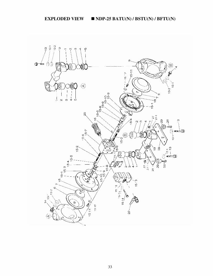
EXPLODED VIEW ���� NDP-25 BATU(N) / BSTU(N) / BFTU(N)
34
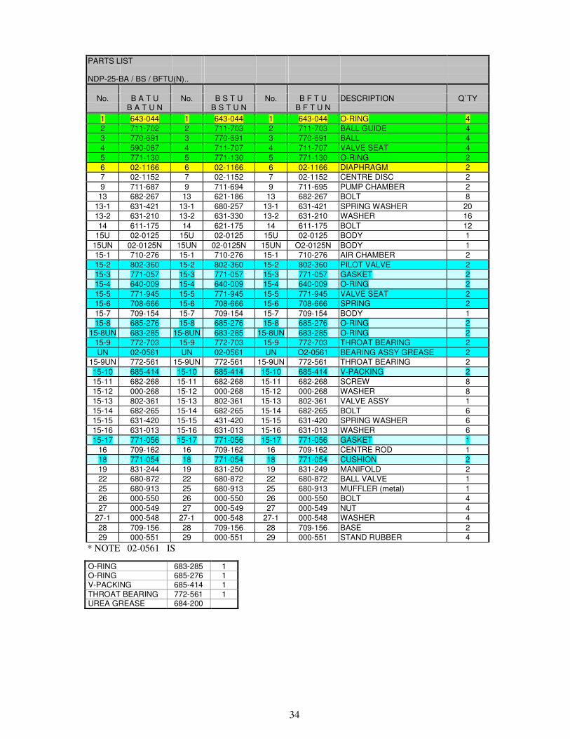
PARTS LIST
NDP-25-BA / BS / BFTU(N)..
No. B A T U No. B S T U No. B F T U DESCRIPTION Q`TY
B A T U N B S T U N B F T U N
1 643-044 1 643-044 1 643-044 O-RING 4
2 711-702 2 711-703 2 711-703 BALL GUIDE 4
3 770-691 3 770-691 3 770-691 BALL 4
4 590-087 4 711-707 4 711-707 VALVE SEAT 4
5 771-130 5 771-130 5 771-130 O-RING 2
6 02-1166 6 02-1166 6 02-1166 DIAPHRAGM 2
7 02-1152 7 02-1152 7 02-1152 CENTRE DISC 2
9 711-687 9 711-694 9 711-695 PUMP CHAMBER 2
13 682-267 13 621-186 13 682-267 BOLT 8
13-1 631-421 13-1 680-257 13-1 631-421 SPRING WASHER 20
13-2 631-210 13-2 631-330 13-2 631-210 WASHER 16
14 611-175 14 621-175 14 611-175 BOLT 12
15U 02-0125 15U 02-0125 15U 02-0125 BODY 1
15UN 02-0125N 15UN 02-0125N 15UN O2-0125N BODY 1
15-1 710-276 15-1 710-276 15-1 710-276 AIR CHAMBER 2
15-2 802-360 15-2 802-360 15-2 802-360 PILOT VALVE 2
15-3 771-057 15-3 771-057 15-3 771-057 GASKET 2
15-4 640-009 15-4 640-009 15-4 640-009 O-RING 2
15-5 771-945 15-5 771-945 15-5 771-945 VALVE SEAT 2
15-6 708-666 15-6 708-666 15-6 708-666 SPRING 2
15-7 709-154 15-7 709-154 15-7 709-154 BODY 1
15-8 685-276 15-8 685-276 15-8 685-276 O-RING 2
15-8UN 683-285 15-8UN 683-285 15-8UN 683-285 O-RING 2
15-9 772-703 15-9 772-703 15-9 772-703 THROAT BEARING 2
UN 02-0561 UN 02-0561 UN O2-0561 BEARING ASSY GREASE 2
15-9UN 772-561 15-9UN 772-561 15-9UN 772-561 THROAT BEARING 2
15-10 685-414 15-10 685-414 15-10 685-414 V-PACKING 2
15-11 682-268 15-11 682-268 15-11 682-268 SCREW 8
15-12 000-268 15-12 000-268 15-12 000-268 WASHER 8
15-13 802-361 15-13 802-361 15-13 802-361 VALVE ASSY 1
15-14 682-265 15-14 682-265 15-14 682-265 BOLT 6
15-15 631-420 15-15 431-420 15-15 631-420 SPRING WASHER 6
15-16 631-013 15-16 631-013 15-16 631-013 WASHER 6
15-17 771-056 15-17 771-056 15-17 771-056 GASKET 1
16 709-162 16 709-162 16 709-162 CENTRE ROD 1
18 771-054 18 771-054 18 771-054 CUSHION 2
19 831-244 19 831-250 19 831-249 MANIFOLD 2
22 680-872 22 680-872 22 680-872 BALL VALVE 1
25 680-913 25 680-913 25 680-913 MUFFLER (metal) 1
26 000-550 26 000-550 26 000-550 BOLT 4
27 000-549 27 000-549 27 000-549 NUT 4
27-1 000-548 27-1 000-548 27-1 000-548 WASHER 4
28 709-156 28 709-156 28 709-156 BASE 2
29 000-551 29 000-551 29 000-551 STAND RUBBER 4
* NOTE 02-0561 IS
O-RING 683-285 1 O-RING 685-276 1 V-PACKING 685-414 1 THROAT BEARING 772-561 1 UREA GREASE 684-200

35
EXPLODED VIEW ���� NDP-25 BP���� , BV����
36
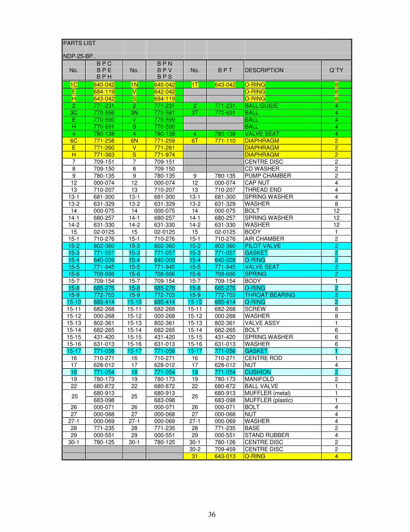
PARTS LIST
NDP-25-BP..
B P C B P N No. B P E No. B P V No. B P T DESCRIPTION Q`TY
B P H B P S
1C 640-042 1N 640-042 1T 643-042 O-RING 8
E 684-119 V 642-042 O-RING 8
H 643-042 S 684-119 O-RING 8
2 771-231 2 771-231 2 771-231 BALL GUIDE 4
3C 770-556 3N 770-581 3T 770-691 BALL 4
E 770-590 V 770-599 BALL 4
H 770-691 S 770-590 BALL 4
4 780-138 4 780-138 4 780-138 VALVE SEAT 4
6C 771-258 6N 771-259 6T 771-110 DIAPHRAGM 2
E 771-260 V 771-261 DIAPHRAGM 2
H 771-363 S 771-974 DIAPHRAGM 2
7 709-151 7 709-151 CENTRE DISC 2
8 709-150 8 709-150 CD WASHER 2
9 780-135 9 780-135 9 780-135 PUMP CHAMBER 2
12 000-074 12 000-074 12 000-074 CAP NUT 4
13 710-207 13 710-207 13 710-207 THREAD END 4
13-1 681-300 13-1 681-300 13-1 681-300 SPRING WASHER 4
13-2 631-329 13-2 631-329 13-2 631-329 WASHER 8
14 000-075 14 000-075 14 000-075 BOLT 12
14-1 680-257 14-1 680-257 14-1 680-257 SPRING WASHER 12
14-2 631-330 14-2 631-330 14-2 631-330 WASHER 12
15 02-0125 15 02-0125 15 02-0125 BODY 1
15-1 710-276 15-1 710-276 15-1 710-276 AIR CHAMBER 2
15-2 802-360 15-2 802-360 15-2 802-360 PILOT VALVE 2
15-3 771-057 15-3 771-057 15-3 771-057 GASKET 2
15-4 640-009 15-4 640-009 15-4 640-009 O-RING 2
15-5 771-945 15-5 771-945 15-5 771-945 VALVE SEAT 2
15-6 708-666 15-6 708-666 15-6 708-666 SPRING 2
15-7 709-154 15-7 709-154 15-7 709-154 BODY 1
15-8 685-276 15-8 685-276 15-8 685-276 O-RING 2
15-9 772-703 15-9 772-703 15-9 772-703 THROAT BEARING 2
15-10 685-414 15-10 685-414 15-10 685-414 O-RING 2
15-11 682-268 15-11 682-268 15-11 682-268 SCREW 8
15-12 000-268 15-12 000-268 15-12 000-268 WASHER 8
15-13 802-361 15-13 802-361 15-13 802-361 VALVE ASSY 1
15-14 682-265 15-14 682-265 15-14 682-265 BOLT 6
15-15 431-420 15-15 431-420 15-15 431-420 SPRING WASHER 6
15-16 631-013 15-16 631-013 15-16 631-013 WASHER 6
15-17 771-056 15-17 771-056 15-17 771-056 GASKET 1
16 710-271 16 710-271 16 710-271 CENTRE ROD 1
17 628-012 17 628-012 17 628-012 NUT 4
18 771-054 18 771-054 18 771-054 CUSHION 2
19 780-173 19 780-173 19 780-173 MANIFOLD 2
22 680-872 22 680-872 22 680-872 BALL VALVE 1
680-913 680-913 680-913 MUFFLER (metal) 1 25
683-098 25
683-098 25
683-098 MUFFLER (plastic) 1
26 000-071 26 000-071 26 000-071 BOLT 4
27 000-068 27 000-068 27 000-068 NUT 4
27-1 000-069 27-1 000-069 27-1 000-069 WASHER 4
28 771-235 28 771-235 28 771-235 BASE 2
29 000-551 29 000-551 29 000-551 STAND RUBBER 4
30-1 780-125 30-1 780-125 30-1 780-126 CENTRE DISC 2
30-2 709-459 CENTRE DISC 2
31 643-013 O-RING 4

37
PARTS LIST
NDP-25-BV..
B V C B V N No. B V E No. B V V No. B V T DESCRIPTION Q`TY
B V H B V S
1C 640-042 1N 640-042 1T 643-042 O-RING 8
E 684-119 V 642-042 O-RING 8
H 643-042 S 684-119 O-RING 8
2 780-141 2 780-141 2 780-141 BALL GUIDE 4
3C 770-556 3N 770-581 3T 770-691 BALL 4
E 770-590 V 770-599 BALL 4
H 770-691 S 770-590 BALL 4
4 780-139 4 780-139 4 780-139 VALVE SEAT 4
6C 771-258 6N 771-259 6T 771-110 DIAPHRAGM 2
E 771-260 V 771-261 DIAPHRAGM 2
H 771-363 S 771-974 DIAPHRAGM 2
7 709-151 7 709-151 CENTRE DISC 2
8 709-150 8 709-150 CD WASHER 2
9 780-136 9 780-136 9 780-136 PUMP CHAMBER 2
12 000-074 12 000-074 12 000-074 CAP NUT 4
13 710-207 13 710-207 13 710-207 THREAD END 4
13-1 681-300 13-1 681-300 13-1 681-300 SPRING WASHER 4
13-2 631-329 13-2 631-329 13-2 631-329 WASHER 8
14 000-075 14 000-075 14 000-075 BOLT 12
14-1 680-257 14-1 680-257 14-1 680-257 SPRING WASHER 12
14-2 631-330 14-2 631-330 14-2 631-330 WASHER 12
15 02-0125 15 02-0125 15 02-0125 BODY 1
15-1 710-276 15-1 710-276 15-1 710-276 AIR CHAMBER 2
15-2 802-360 15-2 802-360 15-2 802-360 PILOT VALVE 2
15-3 771-057 15-3 771-057 15-3 771-057 GASKET 2
15-4 640-009 15-4 640-009 15-4 640-009 O-RING 2
15-5 771-945 15-5 771-945 15-5 771-945 VALVE SEAT 2
15-6 708-666 15-6 708-666 15-6 708-666 SPRING 2
15-7 709-154 15-7 709-154 15-7 709-154 BODY 1
15-8 685-276 15-8 685-276 15-8 685-276 O-RING 2
15-9 772-703 15-9 772-703 15-9 772-703 THROAT BEARING 2
15-10 685-414 15-10 685-414 15-10 685-414 O-RING 2
15-11 682-268 15-11 682-268 15-11 682-268 SCREW 8
15-12 000-268 15-12 000-268 15-12 000-268 WASHER 8
15-13 802-361 15-13 802-361 15-13 802-361 VALVE ASSY 1
15-14 682-265 15-14 682-265 15-14 682-265 BOLT 6
15-15 431-420 15-15 431-420 15-15 431-420 SPRING WASHER 6
15-16 631-013 15-16 631-013 15-16 631-013 WASHER 6
15-17 771-056 15-17 771-056 15-17 771-056 GASKET 1
16 710-271 16 710-271 16 710-271 CENTRE ROD 1
17 628-012 17 628-012 17 628-012 NUT 4
18 771-054 18 771-054 18 771-054 CUSHION 2
19 780-174 19 780-174 19 780-174 MANIFOLD 2
22 680-872 22 680-872 22 680-872 BALL VALVE 1
680-913 680-913 680-913 MUFFLER (metal) 1 25
683-098 25
683-098 25
683-098 MUFFLER (plastic) 1
26 000-071 26 000-071 26 000-071 BOLT 4
27 000-068 27 000-068 27 000-068 NUT 4
27-1 000-069 27-1 000-069 27-1 000-069 WASHER 4
28 771-749 28 771-749 28 771-749 BASE 2
29 000-551 29 000-551 29 000-551 STAND RUBBER 4
30-1 780-127 30-1 780-127 30-1 780-128 CENTRE DISC 2
30-2 709-459 CENTRE DISC 2
31 643-013 O-RING 4

38
EXPLODED VIEW ���� NDP-25 BPTU(N) / BVTU(N)
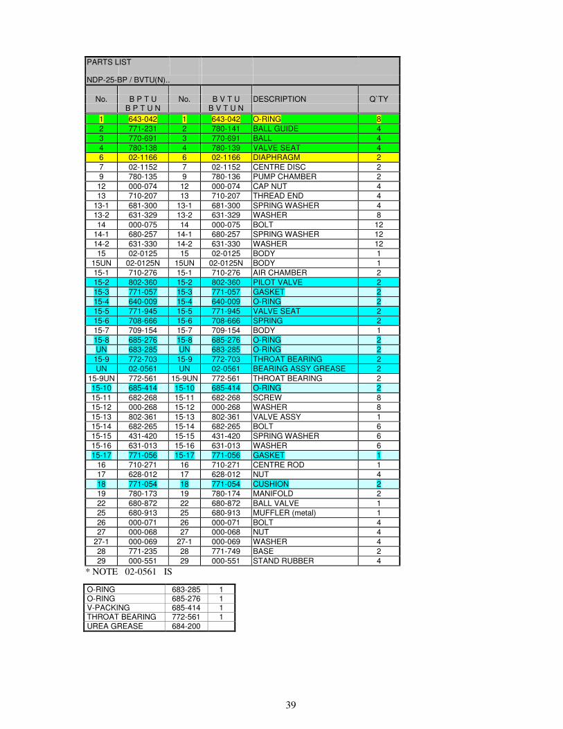
39
PARTS LIST
NDP-25-BP / BVTU(N)..
No. B P T U No. B V T U DESCRIPTION Q`TY
B P T U N B V T U N
1 643-042 1 643-042 O-RING 8
2 771-231 2 780-141 BALL GUIDE 4
3 770-691 3 770-691 BALL 4
4 780-138 4 780-139 VALVE SEAT 4
6 02-1166 6 02-1166 DIAPHRAGM 2
7 02-1152 7 02-1152 CENTRE DISC 2
9 780-135 9 780-136 PUMP CHAMBER 2
12 000-074 12 000-074 CAP NUT 4
13 710-207 13 710-207 THREAD END 4
13-1 681-300 13-1 681-300 SPRING WASHER 4
13-2 631-329 13-2 631-329 WASHER 8
14 000-075 14 000-075 BOLT 12
14-1 680-257 14-1 680-257 SPRING WASHER 12
14-2 631-330 14-2 631-330 WASHER 12
15 02-0125 15 02-0125 BODY 1
15UN 02-0125N 15UN 02-0125N BODY 1
15-1 710-276 15-1 710-276 AIR CHAMBER 2
15-2 802-360 15-2 802-360 PILOT VALVE 2
15-3 771-057 15-3 771-057 GASKET 2
15-4 640-009 15-4 640-009 O-RING 2
15-5 771-945 15-5 771-945 VALVE SEAT 2
15-6 708-666 15-6 708-666 SPRING 2
15-7 709-154 15-7 709-154 BODY 1
15-8 685-276 15-8 685-276 O-RING 2
UN 683-285 UN 683-285 O-RING 2
15-9 772-703 15-9 772-703 THROAT BEARING 2
UN 02-0561 UN 02-0561 BEARING ASSY GREASE 2
15-9UN 772-561 15-9UN 772-561 THROAT BEARING 2
15-10 685-414 15-10 685-414 O-RING 2
15-11 682-268 15-11 682-268 SCREW 8
15-12 000-268 15-12 000-268 WASHER 8
15-13 802-361 15-13 802-361 VALVE ASSY 1
15-14 682-265 15-14 682-265 BOLT 6
15-15 431-420 15-15 431-420 SPRING WASHER 6
15-16 631-013 15-16 631-013 WASHER 6
15-17 771-056 15-17 771-056 GASKET 1
16 710-271 16 710-271 CENTRE ROD 1
17 628-012 17 628-012 NUT 4
18 771-054 18 771-054 CUSHION 2
19 780-173 19 780-174 MANIFOLD 2
22 680-872 22 680-872 BALL VALVE 1
25 680-913 25 680-913 MUFFLER (metal) 1
26 000-071 26 000-071 BOLT 4
27 000-068 27 000-068 NUT 4
27-1 000-069 27-1 000-069 WASHER 4
28 771-235 28 771-749 BASE 2
29 000-551 29 000-551 STAND RUBBER 4
* NOTE 02-0561 IS
O-RING 683-285 1 O-RING 685-276 1 V-PACKING 685-414 1 THROAT BEARING 772-561 1 UREA GREASE 684-200

40
EXPLODED VIEW ���� NDP-25 BTT, BXT
41
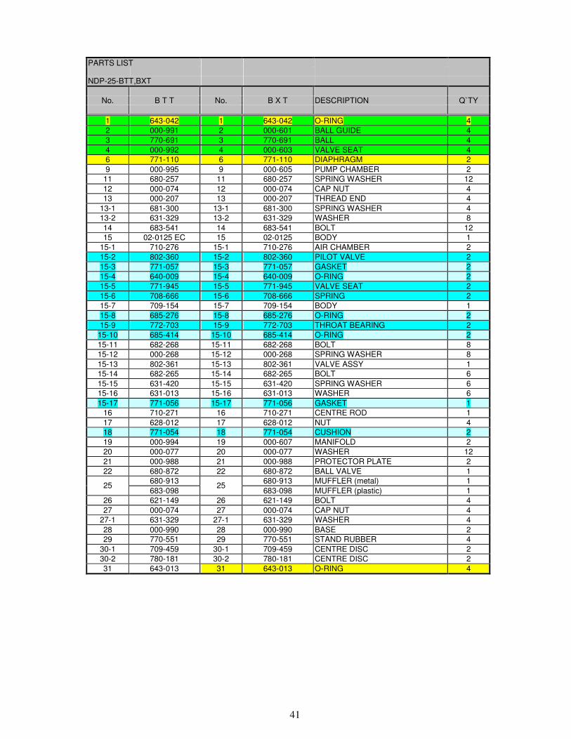
PARTS LIST
NDP-25-BTT,BXT
No. B T T No. B X T DESCRIPTION Q`TY
1 643-042 1 643-042 O-RING 4
2 000-991 2 000-601 BALL GUIDE 4
3 770-691 3 770-691 BALL 4
4 000-992 4 000-603 VALVE SEAT 4
6 771-110 6 771-110 DIAPHRAGM 2
9 000-995 9 000-605 PUMP CHAMBER 2
11 680-257 11 680-257 SPRING WASHER 12
12 000-074 12 000-074 CAP NUT 4
13 000-207 13 000-207 THREAD END 4
13-1 681-300 13-1 681-300 SPRING WASHER 4
13-2 631-329 13-2 631-329 WASHER 8
14 683-541 14 683-541 BOLT 12
15 02-0125 EC 15 02-0125 BODY 1
15-1 710-276 15-1 710-276 AIR CHAMBER 2
15-2 802-360 15-2 802-360 PILOT VALVE 2
15-3 771-057 15-3 771-057 GASKET 2
15-4 640-009 15-4 640-009 O-RING 2
15-5 771-945 15-5 771-945 VALVE SEAT 2
15-6 708-666 15-6 708-666 SPRING 2
15-7 709-154 15-7 709-154 BODY 1
15-8 685-276 15-8 685-276 O-RING 2
15-9 772-703 15-9 772-703 THROAT BEARING 2
15-10 685-414 15-10 685-414 O-RING 2
15-11 682-268 15-11 682-268 BOLT 8
15-12 000-268 15-12 000-268 SPRING WASHER 8
15-13 802-361 15-13 802-361 VALVE ASSY 1
15-14 682-265 15-14 682-265 BOLT 6
15-15 631-420 15-15 631-420 SPRING WASHER 6
15-16 631-013 15-16 631-013 WASHER 6
15-17 771-056 15-17 771-056 GASKET 1
16 710-271 16 710-271 CENTRE ROD 1
17 628-012 17 628-012 NUT 4
18 771-054 18 771-054 CUSHION 2
19 000-994 19 000-607 MANIFOLD 2
20 000-077 20 000-077 WASHER 12
21 000-988 21 000-988 PROTECTOR PLATE 2
22 680-872 22 680-872 BALL VALVE 1
680-913 680-913 MUFFLER (metal) 1 25
683-098 25
683-098 MUFFLER (plastic) 1
26 621-149 26 621-149 BOLT 4
27 000-074 27 000-074 CAP NUT 4
27-1 631-329 27-1 631-329 WASHER 4
28 000-990 28 000-990 BASE 2
29 770-551 29 770-551 STAND RUBBER 4
30-1 709-459 30-1 709-459 CENTRE DISC 2
30-2 780-181 30-2 780-181 CENTRE DISC 2
31 643-013 31 643-013 O-RING 4
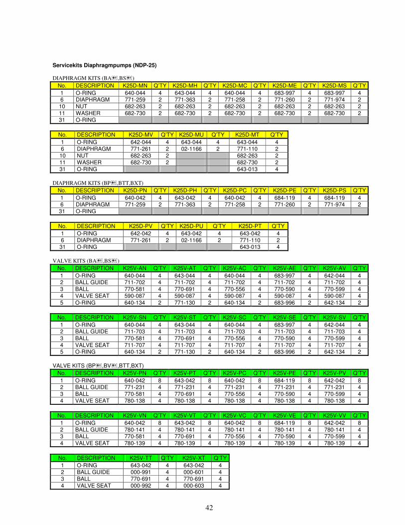
42
Servicekits Diaphragmpumps (NDP-25) DIAPHRAGM KITS (BA�,BS�)
No. DESCRIPTION K25D-MN Q’TY K25D-MH Q’TY K25D-MC Q’TY K25D-ME Q’TY K25D-MS Q’TY
1 O-RING 640-044 4 643-044 4 640-044 4 683-997 4 683-997 4 6 DIAPHRAGM 771-259 2 771-363 2 771-258 2 771-260 2 771-974 2 10 NUT 682-263 2 682-263 2 682-263 2 682-263 2 682-263 2
11 WASHER 682-730 2 682-730 2 682-730 2 682-730 2 682-730 2 31 O-RING
No. DESCRIPTION K25D-MV Q’TY K25D-MU Q’TY K25D-MT Q’TY
1 O-RING 642-044 4 643-044 4 643-044 4 6 DIAPHRAGM 771-261 2 02-1166 2 771-110 2 10 NUT 682-263 2 682-263 2 11 WASHER 682-730 2 682-730 2 31 O-RING 643-013 4
DIAPHRAGM KITS (BP�,BTT,BXT)
No. DESCRIPTION K25D-PN Q’TY K25D-PH Q’TY K25D-PC Q’TY K25D-PE Q’TY K25D-PS Q’TY
1 O-RING 640-042 4 643-042 4 640-042 4 684-119 4 684-119 4 6 DIAPHRAGM 771-259 2 771-363 2 771-258 2 771-260 2 771-974 2 31 O-RING
No. DESCRIPTION K25D-PV Q’TY K25D-PU Q’TY K25D-PT Q’TY
1 O-RING 642-042 4 643-042 4 643-042 4 6 DIAPHRAGM 771-261 2 02-1166 2 771-110 2 31 O-RING 643-013 4
VALVE KITS (BA�,BS�)
No. DESCRIPTION K25V-AN Q’TY K25V-AT Q’TY K25V-AC Q’TY K25V-AE Q’TY K25V-AV Q’TY
1 O-RING 640-044 4 643-044 4 640-044 4 683-997 4 642-044 4 2 BALL GUIDE 711-702 4 711-702 4 711-702 4 711-702 4 711-702 4 3 BALL 770-581 4 770-691 4 770-556 4 770-590 4 770-599 4 4 VALVE SEAT 590-087 4 590-087 4 590-087 4 590-087 4 590-087 4
5 O-RING 640-134 2 771-130 2 640-134 2 683-996 2 642-134 2
No. DESCRIPTION K25V-SN Q’TY K25V-ST Q’TY K25V-SC Q’TY K25V-SE Q’TY K25V-SV Q’TY
1 O-RING 640-044 4 643-044 4 640-044 4 683-997 4 642-044 4 2 BALL GUIDE 711-703 4 711-703 4 711-703 4 711-703 4 711-703 4
3 BALL 770-581 4 770-691 4 770-556 4 770-590 4 770-599 4 4 VALVE SEAT 711-707 4 711-707 4 711-707 4 711-707 4 711-707 4 5 O-RING 640-134 2 771-130 2 640-134 2 683-996 2 642-134 2
VALVE KITS (BP�,BV�,BTT,BXT)
No. DESCRIPTION K25V-PN Q’TY K25V-PT Q’TY K25V-PC Q’TY K25V-PE Q’TY K25V-PV Q’TY
1 O-RING 640-042 8 643-042 8 640-042 8 684-119 8 642-042 8 2 BALL GUIDE 771-231 4 771-231 4 771-231 4 771-231 4 771-231 4 3 BALL 770-581 4 770-691 4 770-556 4 770-590 4 770-599 4 4 VALVE SEAT 780-138 4 780-138 4 780-138 4 780-138 4 780-138 4
No. DESCRIPTION K25V-VN Q’TY K25V-VT Q’TY K25V-VC Q’TY K25V-VE Q’TY K25V-VV Q’TY
1 O-RING 640-042 8 643-042 8 640-042 8 684-119 8 642-042 8 2 BALL GUIDE 780-141 4 780-141 4 780-141 4 780-141 4 780-141 4 3 BALL 770-581 4 770-691 4 770-556 4 770-590 4 770-599 4
4 VALVE SEAT 780-139 4 780-139 4 780-139 4 780-139 4 780-139 4
No. DESCRIPTION K25V-TT Q’TY K25V-XT Q’TY
1 O-RING 643-042 4 643-042 4 2 BALL GUIDE 000-991 4 000-601 4 3 BALL 770-691 4 770-691 4 4 VALVE SEAT 000-992 4 000-603 4
43
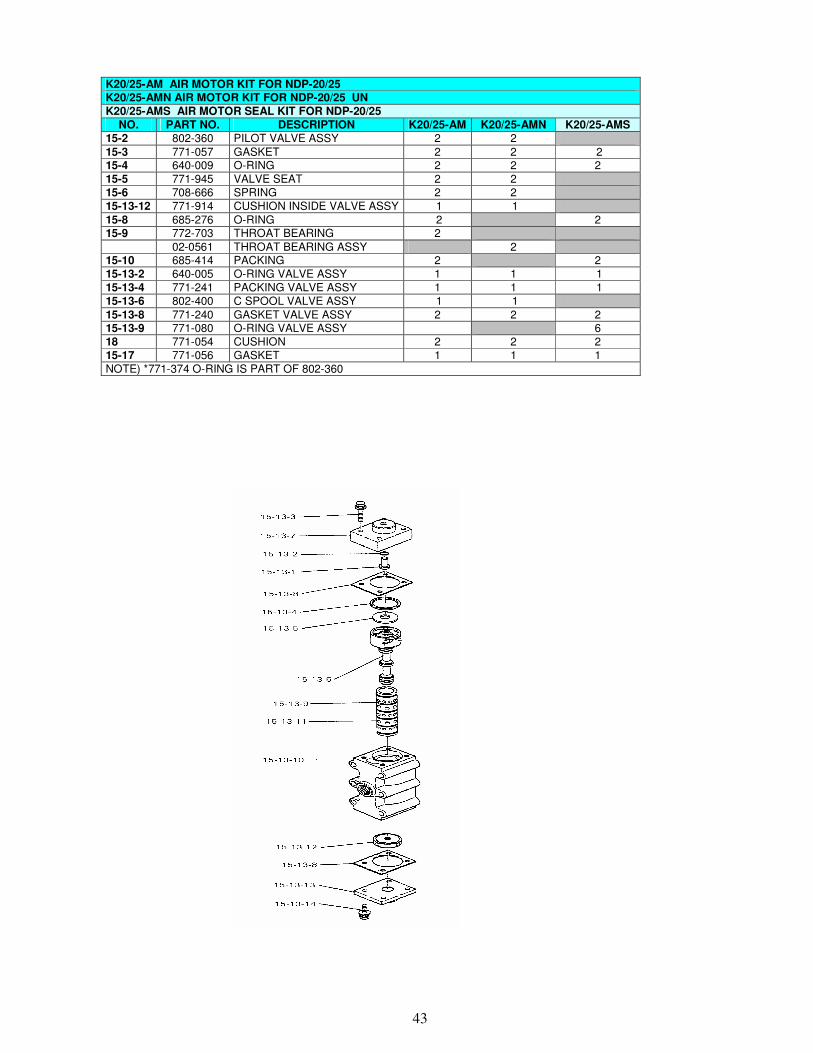
K20/25-AM AIR MOTOR KIT FOR NDP-20/25 K20/25-AMN AIR MOTOR KIT FOR NDP-20/25 UN
K20/25-AMS AIR MOTOR SEAL KIT FOR NDP-20/25
NO. PART NO. DESCRIPTION K20/25-AM K20/25-AMN K20/25-AMS
15-2 802-360 PILOT VALVE ASSY 2 2
15-3 771-057 GASKET 2 2 2 15-4 640-009 O-RING 2 2 2 15-5 771-945 VALVE SEAT 2 2 15-6 708-666 SPRING 2 2 15-13-12 771-914 CUSHION INSIDE VALVE ASSY 1 1
15-8 685-276 O-RING 2 2 15-9 772-703 THROAT BEARING 2
02-0561 THROAT BEARING ASSY 2 15-10 685-414 PACKING 2 2 15-13-2 640-005 O-RING VALVE ASSY 1 1 1 15-13-4 771-241 PACKING VALVE ASSY 1 1 1 15-13-6 802-400 C SPOOL VALVE ASSY 1 1
15-13-8 771-240 GASKET VALVE ASSY 2 2 2 15-13-9 771-080 O-RING VALVE ASSY 6 18 771-054 CUSHION 2 2 2 15-17 771-056 GASKET 1 1 1 NOTE) *771-374 O-RING IS PART OF 802-360
44
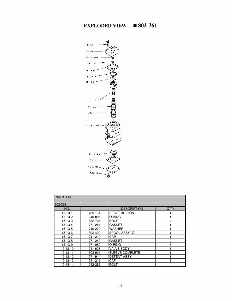
EXPLODED VIEW ���� 802-361
PARTS LIST
802-361
NO. DESCRIPTION Q’TY
15-13-1 709-161 RESET BUTTON 1
15-13-2 640-005 O-RING 1
15-13-3 682-704 BOLT 4
15-13-4 771-241 GASKET 1
15-13-5 710-270 WASHER 1
15-13-6 802-400 SPOOL ASSY "C" 1
15-13-7 711-219 CAP 1
15-13-8 771-240 GASKET 2
15-13-9 771-080 O-RING 6
15-13-10 711-638 VALVE BODY 1
15-13-11 803-931 SLEEVE COMPLETE 1
15-13-12 771-914 DETENT ASSY 1
15-13-13 711-212 CAP 1
15-13-14 682-262 BOLT 4

45
Yamada Europe BV � +31.74.242 2032
Aquamarijnstraat 50 � +31.74.242 1055
NL-7554 NS Hengelo [email protected]
The Netherlands www.yamada.nl