Maintenance Manual 14R RideSentry™ MPA Series Sliding Tandem...
32
Maintenance Manual 14R RideSentry™ MPA Series Sliding Tandem Trailer Air Suspension System Revised 05-14
Transcript of Maintenance Manual 14R RideSentry™ MPA Series Sliding Tandem...

Maintenance Manual 14R
RideSentry™ MPA Series Sliding Tandem Trailer Air Suspension SystemRevised 05-14

Service Notes
Information contained in this publication was in effect at the time the publication was approved for printing and is subject to change without notice or liability. Meritor Heavy Vehicle Systems, LLC, reserves the right to revise the information presented or to discontinue the production of parts described at any time.
Meritor Maintenance Manual 14R (Revised 05-14)
About This ManualThis manual provides the correct lubrication, service and installation procedures for the Meritor RideSentry™ MPA Series sliding tandem trailer air suspension system.
Before You Begin1. Read and understand all instructions and procedures before
you begin to service components.
2. Read and observe all Warning and Caution hazard alert messages in this publication. They provide information that can help prevent serious personal injury, damage to components, or both.
3. Follow your company’s maintenance and service, installation, and diagnostics guidelines.
4. Use special tools when required to help avoid serious personal injury and damage to components.
Hazard Alert Messages and Torque Symbols
WARNINGA Warning alerts you to an instruction or procedure that you must follow exactly to avoid serious personal injury and damage to components.
CAUTIONA Caution alerts you to an instruction or procedure that you must follow exactly to avoid damage to components.
@ This symbol alerts you to tighten fasteners to a specified torque value.
How to Obtain Additional Maintenance, Service and Product InformationVisit Literature on Demand at meritor.com to access and order additional information.
Contact the Meritor OnTrac™ Customer Call Center at 866-668-7221 (United States and Canada); 001-800-889-1834 (Mexico); or email [email protected].
If Tools and Supplies are Specified in This ManualContact Meritor’s Commercial Vehicle Aftermarket at 888-725-9355.

pg. pg.
Contents
1 Section 1: Exploded ViewRideSentry™ MPA Series Sliding Tandem Trailer Air
Suspension System
2 Section 2: IntroductionDescription
3 ComponentsFeatures
4 Identification
5 Section 3: Inspection and MaintenanceInspection
7 MaintenanceSlider
8 Trailer Air SuspensionInspectionHeight Control Valve
9 Axle Inspection and MaintenanceLubrication
10 Section 4: Component Removal, Installation and AdjustmentRemoval and InstallationHeight Control Valve (HCV)HCV Installation Options
11 AdjustmentVerify Ride HeightMaintain the Correct Ride Height When You Change an
HCV12 Removal and Installation
Air Spring14 Upper Control Arm17 Lower Control Arm
Axle Replacement Procedure19 Axle Alignment
Before You Align the AxleFront AxleRear Axle
20 Auto-Dump ConfigurationTo Auto-Dump from No-DumpNo-Dump ConfigurationTo No-Dump from Auto-Dump
21 Section 5: WeldingCheck Welding Procedures Before You Weld to
Suspension ComponentsAxleSuspensionSlider
22 Section 6: Slider Removal, Installation and AdjustmentCheck Body Rail SpecificationsInstallationSlider-to-Trailer Retrofit
24 Slider Repositioning
25 Section 7: DiagnosticsTroubleshooting
27 Section 8: SpecificationsTorque Specifications
28 Section 9: Special ToolsTool Drawing

1 Exploded View
1Meritor Maintenance Manual 14R (Revised 05-14)
1 Exploded ViewRideSentry™ MPA Series Sliding Tandem Trailer Air Suspension System
Figure 1.1
4006703a14
13
20
6
4
5
5
19
19
7
18
17
15
2123
24
109
16
8
8
222
3
2
1
1
10
12
11
7
9
Item Description
1 Slider Wear Pad
2 Slider Cross Member
3 Meritor PinLoc™ System
4 Slider Side Rail, Curbside
5 Air Spring
6 Lower Control Arm, Fixed
7 Lower Bushing
8 Lower Inner Sleeve, Bushing Inner Metal
9 Upper Axle Seat
10 Upper Control Arm
11 Lower Axle Seat
12 Upper Bushing
13 Clevis, Shock
14 Axle Assembly, Rear
15 Height Control Linkage
16 Lower Shock Mounting Bracket
17 Shock Absorber
18 Height Control Air Valve (Hadley 1500 Series)
19 Lower Control Arm, Adjustable
20 Axle Assembly, Front
21 Suspension Tag
22 Slider Slide Rail, Roadside
23 Hold Down Clip
24 Lock Pin Operation Label
Item Description

2 Introduction
2 Meritor Maintenance Manual 14R (Revised 05-14)
2 IntroductionDescriptionThe Meritor RideSentry™ MPA Series sliding tandem trailer air suspension system centers around a stabilized parallelogram design that incorporates a single unified frame bracket. The upper and lower control arms are parallel to each other. The air springs mount directly over the axle. Figure 2.1.
Ride height and mounting height are important measurements for overall vehicle height. Measure ride height from the centerline of the axle to the bottom of the slider frame. Measure mounting height from the centerline of the axle to the bottom of the trailer frame. Figure 2.2.
Figure 2.1
Figure 2.1
4006704a
FRAMEBRACKET
AIRSPRING
SHOCKABSORBER
UPPERCONTROL
ARM
LOWERCONTROL
ARM
SLIDERASSEMBLY
CURBSIDE
ROADSIDE

2 Introduction
3Meritor Maintenance Manual 14R (Revised 05-14)
Figure 2.2
Refer to the trailer manufacturer’s specifications for the correct ride height. Note that the nominal ride height, also referred to as the design height, refers to the designed ride height and may not be the same as the actual ride height. To determine the nominal ride height of the RideSentry™ suspension, the following indicators apply.
� 16.5-inch ride height has the air spring mounted directly to the upper axle seat.
� 17.5-inch ride height has a 1.0-inch spacer under the air spring.
� 18.5-inch ride height has two 1.0-inch spacers under the air spring.
Components� Frame brackets and slider assembly
� Upper and lower control arms
� Axle assemblies
� Air springs
� Shock absorbers
Features� A compact 38,000 and 40,000 lb (17 237 and 18 144 kg)
capacity tandem trailer air suspension and slider system designed for sliding tandems.
� Nominal ride heights of 16.5-inches (41.9 cm), 17.5-inches (44.5 cm) and 18.5-inches (47.0 cm) are offered with eight inches (20.3 cm) of total travel for the 16.5- and 17.5-inch ride heights. The 18.5-inch ride height has seven inches of total travel.
� A mounting height of 24.5-26.5-inches (62.2-67.3 cm).
Figure 2.2
4006705a
LOCKING PINSLIDER
RIDEHEIGHT
MOUNTINGHEIGHT
ROADSIDE
AXLE

2 Introduction
4 Meritor Maintenance Manual 14R (Revised 05-14)
IdentificationThe identification tag is located on the roadside of the suspension near the front of the slider side rail. Figure 2.3.
Figure 2.3
The model number on the identification tag provides suspension and axle information. Figure 2.4.
Figure 2.4
Figure 2.3
Figure 2.4
STAMPED INFORMATION
Suspension Capacity
Nominal Ride Height
Model Number
Serial Number
FOR SUSPENSION NOMINAL RIDE HEIGHT(NRH), REFER TO THE NRH VALUE INDICATED
ON THIS LABEL. FOR THE ACTUAL RIDEHEIGHT VALUE, REFER TO THE VEHICLE/
TRAILER MANUFACTURER'S SPECIFICATIONSUSP. CAP.
MODEL SERIAL NO.
LB. IN.NRHC
A
B
C
D
A BD
4006707a
ROADSIDE
IDENTIFICATIONTAG
MPA XX S XX XX XXXX
Suspension Model
Axle Type
Nominal Ride HeightSliding Subframe
Suspension Rating x 1000 lbs.
Sequence Number: Can be cross referenced to the Bill of Material.
4006708a
Nominal Ride Height
65 16.5-inches
75 17.5-inches
85 18.5-inches

3 Inspection and Maintenance
5Meritor Maintenance Manual 14R (Revised 05-14)
3 Inspection and MaintenanceHazard Alert MessagesRead and observe all Warning and Caution hazard alert messages in this publication. They provide information that can help prevent serious personal injury, damage to components, or both.
WARNINGTo prevent serious eye injury, always wear safe eye protection when you perform vehicle maintenance or service.
Check fastener torque values, tighten loose fasteners and replace damaged fasteners. Loose, damaged or missing fasteners can cause loss of vehicle control, serious personal injury and damage to components.
Refer to Section 8 for the torque values.
InspectionInspect the suspension, air suspension components, height control valve and axle at regular intervals during normal operation and each time the trailer is serviced.
� Before each trip, visually inspect the system. Listen for air leaks.
After 1,000 Miles (1600 km) and Annually Thereafter1. Visually inspect all fasteners for looseness or movement.
Figure 3.1. Ensure loose fasteners have not caused damage to any suspension components. Tighten loose fasteners to the correct torque specified in Section 8.
� Replace any damaged components and fasteners. Refer to Section 4 for component removal and installation procedures.
� If a loose pivot bolt is at an upper control arm pivot connection: Disassemble the pivot joint at the loose fastener location. Refer to “Upper Control Arm” in Section 4 for the procedures.
2. Replace damaged fasteners to maintain the correct torque specifications to comply with warranty requirements. Refer to Section 8.
3. Visually inspect the upper control arm bushings for ragged or loose pieces that can protrude from the pivot connection area. Damage to components can result.
� If the upper control arm bushings are ragged or have loose pieces that protrude from them: Replace the bushings. Refer to Section 4 for the upper control arm bushing removal and installation procedures.

3 Inspection and Maintenance
6 Meritor Maintenance Manual 14R (Revised 05-14)
Figure 3.1
Figure 3.1
1. Upper Control Arm, Axle End
2. Upper Control Arm, Frame Bracket End — Roadside
3. Upper Control Arm, Frame Bracket End — Curbside
4. Lower Control Arm — Fixed, Axle End
5. Lower Control Arm — Fixed, Frame Bracket End
6. Lower Control Arm — Adjustable, Axle End
7. Lower Control Arm — Adjustable, Frame Bracket End
8. Lower Control Arm — Adjustable, Clamp Bolt
9. Upper Air Spring Nut, 3/4-16 NF
10. Upper Air Spring Nut, 1/2-13 NC
11. Lower Air Spring Nut
12. Shock Absorber — Upper and Lower
13. Height Control Linkage — Upper and Lower
14. Height Control Valve Mounting Bolt
15. Slider Hold Down Clip
ROADSIDE
BOLT KITS
ROADSIDE
9 10 10 9
9 10 10 9
14
13
11
12
6/4
87/5*86/4
15
2/3*
11
15
12
*CURBSIDE SIMILAR4006709a
CURBSIDE
FRONT
3 Inspection and Maintenance
7Meritor Maintenance Manual 14R (Revised 05-14)
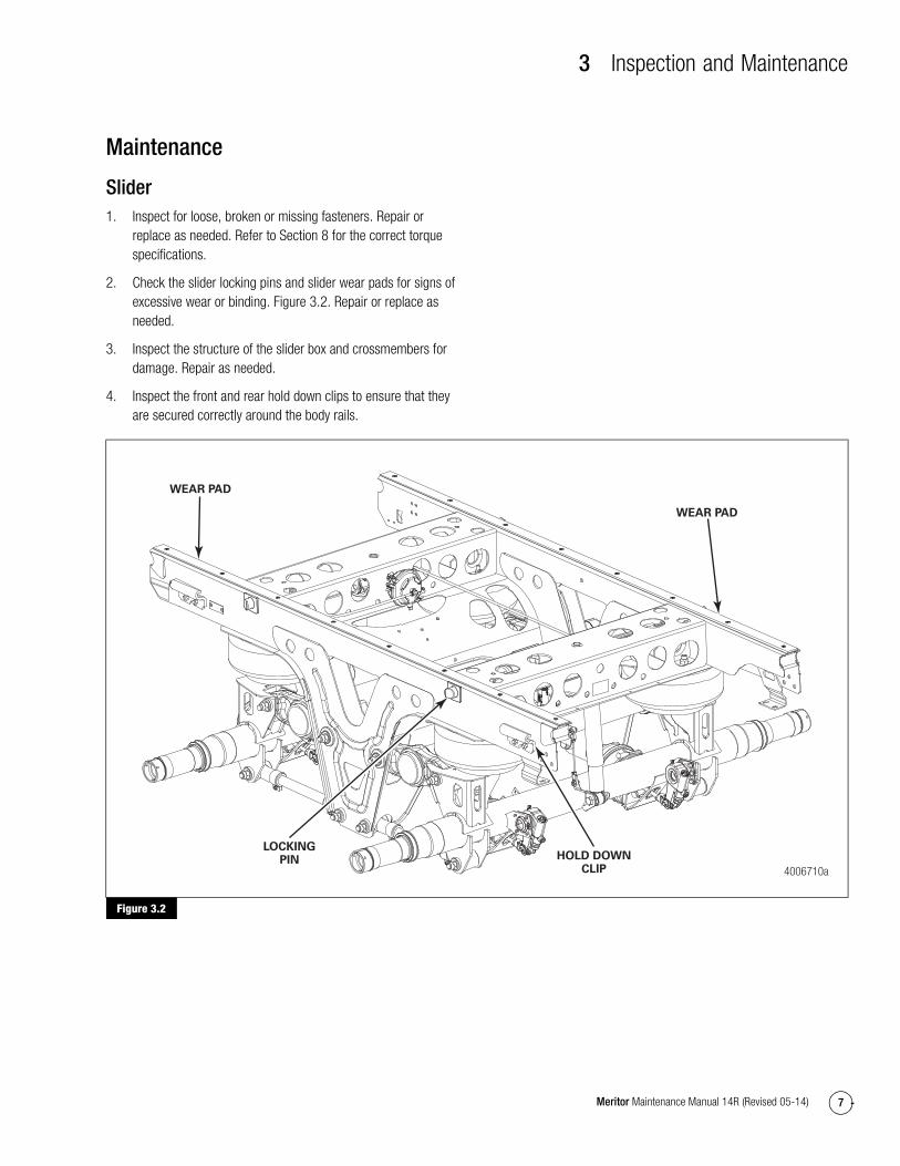
Maintenance
Slider1. Inspect for loose, broken or missing fasteners. Repair or
replace as needed. Refer to Section 8 for the correct torque specifications.
2. Check the slider locking pins and slider wear pads for signs of excessive wear or binding. Figure 3.2. Repair or replace as needed.
3. Inspect the structure of the slider box and crossmembers for damage. Repair as needed.
4. Inspect the front and rear hold down clips to ensure that they are secured correctly around the body rails.
Figure 3.2
Figure 3.2
4006710a
WEAR PAD
WEAR PAD
HOLD DOWNCLIP
LOCKINGPIN

3 Inspection and Maintenance
8 Meritor Maintenance Manual 14R (Revised 05-14)
Trailer Air Suspension1. Inspect for loose, broken or missing fasteners. Repair or
replace as needed. Refer to Section 8 for the correct torque specifications.
2. Inspect the welds for cracks at the axle, frame bracket and upper control arm crosstube.
3. Inspect the bushings for ragged or loose pieces that can protrude from the connection area.
� If the condition exists: Contact the Meritor OnTrac™ Customer Call Center at 866-668-7221.
4. Inspect the flex member of the air springs for cuts and abrasions. Replace the air spring if it is cut or damaged.
5. Check for obstructions or interference to the air spring surface that can damage the air spring. Relocate and secure items, such as air hoses, that can contact the air spring.
6. Check for leaks in the air lines at the air spring bead plate, piston and mounting studs. Replace air lines, fittings or air springs that leak. Refer to Section 4.
7. Inspect the shock absorbers for worn bushings, oil leaks and dents. Check that the mounting holes have not enlarged.
8. After normal operation, check the shock absorbers for heat.
� Warm shock absorbers most likely indicate that the shock absorbers are operating correctly.
� Cold shock absorbers can indicate that the shock absorbers are not operating correctly and must be replaced. Replace the shock absorbers as necessary.
9. Inspect the structure of the suspension. Figure 3.3. Inspect the following items.
� Upper axle seats
� Upper control arms
� Lower axle seats
� Lower control arms
� Axle welds
� Brake interference, cam or chamber
� Frame brackets
� Shock absorber brackets
Figure 3.3
Inspection
Height Control ValveThere are three basic configurations for plumbing the height control valve (HCV) into the air suspension system.
� No-dump
The no-dump configuration is standard equipment. In the no-dump configuration, the valve maintains air pressure and enables the trailer to maintain ride height during loading and unloading, if it is attached to an air supply.
� Auto-dump
The auto-dump configuration will exhaust the air springs when the trailer parking brakes are set. This lowers the trailer deck height three-inches providing a stable platform for loading and unloading. The trailer will return to the ride height when the parking brakes are released.
� Manual-dump/auto-reset
The manual-dump/auto-reset configuration offers the same feature as auto-dump, except at the operator’s discretion.
WARNINGPark the vehicle on a level surface. Block the wheels to prevent the vehicle from moving. Support the vehicle with safety stands. Do not work under a vehicle supported only by jacks. Jacks can slip and fall over. Serious personal injury and damage to components can result.
1. Park the unloaded vehicle on a level surface. Block the wheels to prevent the vehicle from moving.
2. Disconnect the height control linkage. Figure 3.4.
Figure 3.3
4006711a
UPPERAXLESEAT
LOWERAXLESEAT
LOWERCONTROL
ARMS
UPPERCONTROL
ARM
FRAMEBRACKET

3 Inspection and Maintenance
9Meritor Maintenance Manual 14R (Revised 05-14)
Figure 3.4
WARNINGVerify that all personnel are clear of the trailer before you inflate or deflate the air springs. The air suspension system has various pinch points that can cause serious personal injury.
3. Check the air supply to the height control valve. A minimum of 65 psi (448 kPa) is required to correctly test the height control valve.
4. Rotate the lever UP 30 to 45 degrees. Air should begin to flow into the air springs.
5. Rotate the lever to the neutral position. Airflow should stop.
6. Rotate the lever DOWN 30 to 45 degrees. Air should begin to flow out of the air springs.
7. Rotate the lever to the neutral position. Airflow should stop.
� If the air does not flow to and from the air springs: Drain the air from the system. Use compressed air to clean the screens in the supply and delivery ports.
8. Connect the air lines to the height control valve and repeat the above steps.
� If air still does not flow to and from the air springs, or if the airflow cannot be stopped in the neutral position: Replace the height control valve.
9. Inspect the height control valve for air leaks and a cracked lever arm housing.
� If air leaks or cracks are detected: Replace the height control valve.
Axle Inspection and MaintenanceFor correct inspection and maintenance procedures and intervals, refer to Maintenance Manual 14, Trailer Axles. To obtain this publication, refer to the Service Notes page on the front inside cover of this manual.
LubricationThe RideSentry™ MPA Series slider box or suspension does not require lubrication. For lubrication and maintenance requirements for axles, hubs and brakes, refer to Maintenance Manual 14, Trailer Axles; and Maintenance Manual 1, Preventive Maintenance and Lubrication. To obtain these publications, refer to the Service Notes page on the front inside cover of this manual.
Figure 3.4
4006712a
HEIGHTCONTROLLINKAGE 30°-45°
30°-45°

4 Component Removal, Installation and Adjustment
10 Meritor Maintenance Manual 14R (Revised 05-14)
4 Component Removal, Installation and AdjustmentHazard Alert MessagesRead and observe all Warning and Caution hazard alert messages in this publication. They provide information that can help prevent serious personal injury, damage to components, or both.
WARNINGTo prevent serious eye injury, always wear safe eye protection when you perform vehicle maintenance or service.
Park the vehicle on a level surface. Block the wheels to prevent the vehicle from moving. Support the vehicle with safety stands. Do not work under a vehicle supported only by jacks. Jacks can slip and fall over. Serious personal injury and damage to components can result.
Verify that all personnel are clear of the trailer before you inflate or deflate the air springs. The air suspension system has various pinch points that can cause serious personal injury.
Removal and Installation
Height Control Valve (HCV)1. Park the unloaded vehicle on a level surface. Block the wheels
to prevent the vehicle from moving.
2. Drain all the air from the surge tank and air springs.
3. Remove the air supply and delivery lines from the height control valve.
4. Disconnect the linkage. Replace bent or damaged linkage.
5. Remove the height control valve from the bracket. Figure 4.1.
Figure 4.1
6. Install the new HCV onto the mounting bracket. Tighten the mounting bolts to 5 lb-ft (7 N�m). @
7. Connect the linkage. Tighten the upper and lower linkage bolts to 5 lb-ft (7 N�m). @
CAUTIONThe Hadley 1500 HCV is equipped with 3/8-inch (9.525 mm) push-to-connect fittings. Do not use sealant on push-to-connect fittings. Damage to components can result.
8. Connect the air supply and the delivery lines to the height control valve.
9. Charge the air system.
10. Use a soapy spray solution to check the entire system for air leaks.
11. Verify the ride height setting. Refer to the procedures in this section.
HCV Installation OptionsThe suspension may be equipped with a 1500 Series auto-dump configuration or a 1500 Series no-dump configuration. Figure 4.2 and Figure 4.3.
Figure 4.2
Figure 4.1
4006713a
HEIGHTCONTROLVALVE
MOUNTINGBRACKET
Figure 4.2
4006714a
LEVER
SUPPLY PORT
DUMP PILOTPORT
SUSPENSIONPORT
BOLT TORQUE50-55 LB-IN
(6 N•m)
AUTO-DUMP

4 Component Removal, Installation and Adjustment
11Meritor Maintenance Manual 14R (Revised 05-14)
Figure 4.3
Adjustment
Verify Ride Height1. Refer to the trailer manufacturer’s specifications for the correct
ride height.
2. Unload the vehicle before you adjust the height control valve. Support the trailer king pin at the normal operating height.
3. Verify the correct ride height by measuring the ride height from the axle centerline to the bottom of the slider frame.
� If the measured ride height does not meet the trailer manufacturer’s specifications: Continue to the next step.
� If the measured ride height does meet the trailer manufacturer’s specifications: Go to Step 10.
4. Disconnect the height control valve linkage from the lever arm. Inflate or deflate the air springs by raising or lowering the height control lever arm 30 to 45 degrees. Hold the lever arm in the UP position for at least 15 seconds or until the air bags are correctly inflated. Figure 4.4.
Figure 4.4
5. Check the ride height. Figure 4.5. Repeat the previous step until the measured ride height matches the trailer manufacturer’s specified ride height.
Figure 4.5
6. Use a 3/8-inch wrench to loosen the 0.25-inch adjusting screw located on the lever arm body. Allow the lever arm to swing free.
7. Align the end of the lever arm to the top opening of the linkage. Loosely insert the upper linkage bolt.
8. Tighten the 0.25-inch adjusting screw to 50-55 lb-in (6 N�m). @
9. Connect the upper linkage bolt. Tighten the bolt to 5 lb-ft (7 N�m). @
10. Verify that the overall trailer height does not exceed the local legal limit.
� If the ride height is not within the specification: Repeat the ride height adjustment procedure until the ride height is correct.
Maintain the Correct Ride Height When You Change an HCVYou must maintain the correct ride height when you change an HCV. Refer to the trailer manufacturer’s specifications for the correct ride height.
Figure 4.3
Figure 4.4
4006715a
LEVER
BOLT TORQUE50-55 LB-IN
(6 N•m)
NO-DUMP SUPPLY PORT
SUSPENSIONPORT
4006716a
HEIGHTCONTROL
VALVELINKAGE
ADJUSTINGSCREW
Removethis bolt.
30°-45°
INFLATE
DEFLATE
30°-45°
Figure 4.5
4006717a
MOUNTINGHEIGHT
RIDEHEIGHT

4 Component Removal, Installation and Adjustment
12 Meritor Maintenance Manual 14R (Revised 05-14)
Removal and Installation
Air SpringFigure 4.6 shows the standard air spring used on the suspension.
Figure 4.6
The RideSentry™ suspension uses six different air springs based on the suspension model and ride height. Refer to the following table for the air spring part numbers.
1. Refer to the preceding table to identify the specific air spring that is damaged or leaking air.
2. Park the trailer on a level surface. Block the tires to prevent the trailer from moving.
3. Use an appropriate lifting device to raise the trailer to extend the air springs, but not enough to raise the tires off the ground. Support the trailer with safety stands.
4. Verify that all the air has been exhausted from the air system.
5. Remove the air inlet line and fitting from the damaged air spring. Figure 4.7.
Figure 4.6
Air SpringSuspension Model Ride Height
A-2258-F-1410 MPA38 16.5
A-2258-W-1531 MPA38 17.5
A-2258-X-1532 MPA38 18.5
A-2258-E-1461 MPA40 16.5
A-2258-L-1520 MPA40 17.5
A-2258-M-1521 MPA40 18.5
AIR SUPPLYFITTING
TO SLIDERFRAME
TO UPPER AXLE SEAT
AIRSPRING
4002674a

4 Component Removal, Installation and Adjustment
13Meritor Maintenance Manual 14R (Revised 05-14)
Figure 4.7
6. Remove the nuts from the studs that secure the top of the air spring.
7. Remove the nut from the bottom of the air spring. You can reach the nut from inside the front or rear of the upper axle seat.
8. Compress the air spring. Remove the spring from the suspension.
9. Compress the new air spring. Slide the spring into the space between the axle seat and slider frame. Reuse the air spring spacer(s), if originally supplied.
10. Align the air inlet and mounting stud. Insert them into the holes in the slider frame.
11. Install the lower nut. Tighten the lower nut to 30-35 lb-ft (41-47 N�m). @
12. Install the nuts on the top mounting studs. Tighten the 1/2-13 UNC nut to 20-25 lb-ft (30-35 N�m). Tighten the 3/4-16 UNF nut to 45-50 lb-ft (60-70 N�m). @
13. Install the fitting and inlet air line to the top of the air spring. Apply a sealant tape.
14. Seat the valve at the bottom of the air tank. Pressurize the air system.
15. Check that items such as tires, air lines or suspension components do not interfere with the air spring flex members.
16. Use a soap solution to check the entire system for air leaks.
17. Raise the trailer. Remove the safety stands.
18. Verify that the ride height of the trailer is correct.
� If the ride height is incorrect: Adjust the height control lever arm to obtain the correct ride height. Refer to the trailer manufacturer’s specifications for the correct ride height.
Figure 4.7
BRAKEPROTECTION
VALVE
PILOTRELAYVALVE
4006718a
CURBSIDE
ROADSIDE
TOAIR SPRINGS
AIRSPRINGS
TRAILERSPRINGBRAKEVALVE
GLAD HANDSUPPLY
EMERGENCYPARKING,
RED
GLADHAND
CONTROL,BLUE
AIRRESERVOIR
FROM BRAKEPROTECTION
VALVE
HEIGHT CONTROLVALVE

4 Component Removal, Installation and Adjustment
14 Meritor Maintenance Manual 14R (Revised 05-14)
Upper Control Arm
WARNINGVisually inspect upper control arm fasteners to ensure they are tightened to the correct specification. Loose fasteners can damage suspension components. If you find a loose pivot bolt at the upper control arm pivot connection, disassemble the pivot joint to check for damaged components. Tighten loose fasteners. Replace damaged fasteners and components to prevent serious personal injury and damage to components during operation.
Visually inspect the upper control arm bushing inner metal ends for wear. Wear is not permitted between the bushing inner metal and its mating surfaces. Refer to Figure 4.8.
� If there is wear between the bushing inner metal and its mating surface: Replace the upper control arm bushing at the loose fastener location only.
� If a loose fastener is at the frame hanger location and damage is found: Use a roadside or curbside side plate repair kit.
� If a loose fastener is at the upper axle seat and damage is found: Replace the upper axle seat. Contact the Meritor OnTrac™ Customer Call Center at 866-668-7221 for parts and kits.
Figure 4.8
1. Lower the landing gear. Use an appropriate lifting device to raise the trailer frame so that the tires are off the ground. Support the trailer with safety stands. Set the parking brake.
2. Exhaust the air pressure from the suspension air springs. Remove the wheels from the axle where you are removing the bushings to access the pivot bolts.
� If there is corrosion between the pivot bolts and the bushing inner metal: Use an impact wrench to spin the pivot bolt heads at all four connections to disengage the bolts from the corrosion to the bushing inner metal.
3. Remove only the locknut at the frame bracket on the roadside and curbside at the upper pivot connections.
4. Record the pivot bolt orientation. Remove the pivot bolts from the frame brackets. Slide the upper control arm out of the frame brackets to provide access to the bushings.
5. Remove the bushings. Remove any burrs and clean the inside diameter of the upper control arm ends. Figure 4.9.
Figure 4.9
6. Visually inspect the upper control arm bushing tubes, frame brackets and axle seats.
A. You must measure the bore diameter and bushing tube length of all four upper control arm bushing tubes before you install the new bushings. The bore diameter must be 2.240-2.250-inches (56.896-57.150 mm). Figure 4.10. The bushing tube length must be 2.590-inches (65.786 mm) or greater. Figure 4.11.
� If any of the four upper control arm bushing tubes are not within the specifications: Replace the upper control arm.
Figure 4.8
No wear is permittedbetween the bushing
inner metal and itsmating surfaces.
4005083c
BUSHINGTHRUSTWASHER
THRUSTWASHER
BUSHINGINNERMETAL
UPPER CONTROL ARMBUSHING TUBE
Figure 4.9
4006737a
Inspect andremove burrs.

4 Component Removal, Installation and Adjustment
15Meritor Maintenance Manual 14R (Revised 05-14)
B. Inspect the frame brackets and axle seats for wear from contact with the upper control arm bushing inner metal. Wear is not permitted between the bushing inner metal and its mating surfaces.
Figure 4.10
Figure 4.11
7. Using light mineral oil, Meritor specification O-92-B, lightly lubricate the inside diameter of the upper control arm bushing tubes. Figure 4.12.
Figure 4.12
8. Refer to Section 9 for a description of the bushing tool part number A-3256-H-1152.
9. Using light mineral oil, Meritor specification O-92-B, lightly lubricate the outside diameter of the bonded bushing.
10. Place the draw plate onto the inside surface of the upper control arm bushing tube. Figure 4.13.
A. Insert the draw bolt with a flat washer, through the draw plate and bushing tube.
B. Place the bushing over the draw bolt and into the upper control arm bushing tube.
C. Thread the draw nut and flat washer onto the draw bolt until it sets against the bushing.
Figure 4.13
11. Snug the draw bolt while ensuring that the bushing and draw plate rest securely on the upper control arm bushing tube.
12. While holding the draw nut with a wrench, turn the draw bolt CLOCKWISE using a maximum one-half-inch impact at a reduced and steady speed. Draw the bonded bushing into the upper control arm bushing tube.
13. If the bolt stops turning or extreme resistance is present, reverse the impact and loosen the tool assembly. Inspect all components of the tool for damage. Reset the draw plate ensuring that the bonded bushing is correctly seated against the upper control arm bushing tube. Verify lubrication on the bushing and control arm tube and repeat the above procedure.
14. Continue rotating the draw bolt until the bolt stops turning and the bushing is fully inserted. Thread damage to the draw bolt or draw nut can occur if over tightened.
Figure 4.10
Figure 4.11
Figure 4.12
4006738a
Check both endsof each tube.
4006739a
4006740a
LUBRICATEDSURFACE
Figure 4.13
4005082b
DRAWBOLT
FLATWASHER
FLATWASHERUPPER CONTROL
ARM BUSHINGTUBE
DRAWPLATE
DRAWNUTBUSHING

4 Component Removal, Installation and Adjustment
16 Meritor Maintenance Manual 14R (Revised 05-14)
15. Ensure that the bushing is centered in the upper control arm bushing tube from side-to-side. Install the thrust washers onto the bushings. Figure 4.14.
Figure 4.14
16. Position the upper control arm into the frame brackets. Ensure that the thrust washers remain in position on the bushings. Using the recorded pivot bolt orientation, insert a new pivot bolt, flat washers, alignment washers and nut on the roadside. Insert a new pivot bolt, flat washers and nut on the curbside. Figure 4.15.
Figure 4.15
17. Loosely install the roadside and curbside nuts. Do not completely tighten at this time.
18. Remove only the locknuts at the upper axle seat on the roadside and curbside upper pivot connections.
19. Remove the pivot bolts from the upper axle seats. Record the pivot bolt orientation. Slide the upper control arm out of the upper axle seats to provide access to the bushings.
20. Remove the bushings. Remove any burrs and clean the inside diameter of the upper control arm ends. Figure 4.9.
21. Repeat Steps 7-15 to install the bushing.
22. Position the upper control arm into the upper axle seats. Ensure that the thrust washers remain in position on the bushings. Using the recorded pivot bolt orientation, insert a new pivot bolt, flat washers and nut on the roadside and curbside.
23. Loosely install the nuts at the axle seat positions. Do not completely tighten at this time.
24. Determine the correct suspension ride height. Refer to the trailer manufacturer’s specifications. The upper control arm must be at the correct ride height before applying the required torque to all upper pivot bolts. Figure 4.16.
Figure 4.16
25. Install the locknut and tighten to 540-560 lb-ft (732-759 N�m). Figure 4.17. @
Figure 4.14
Figure 4.15
4005083b
BUSHING
THRUSTWASHER
THRUSTWASHER
BOTHDIMENSIONSSHOULD BETHE SAME
± 0.010" (0.25 MM)
UPPER CONTROL ARMBUSHING TUBE
4005084a
PIVOTNUT
PIVOTBOLT
FLATWASHER
FLATWASHER
FRAMEBRACKET/AXLE
SEAT
UPPER CONTROL ARMBUSHING TUBE
THRUSTWASHERS
Figure 4.16
4006719a
MOUNTINGHEIGHT
RIDEHEIGHT
AXLE

4 Component Removal, Installation and Adjustment
17Meritor Maintenance Manual 14R (Revised 05-14)
Figure 4.17
26. Reinstall the wheels and tires. Remove the safety stands at the rear of the trailer. Slowly lower the trailer back down onto the suspension.
27. Check the suspension ride height to verify it is correct. If adjustment is necessary, refer to the ride height adjustment procedures in this section.
28. Axle realignment is required. Refer to the axle alignment procedures in this section.
29. Refer to Section 8 for torque specifications.
Lower Control Arm1. Park the trailer on a level surface.
2. Lower the landing gear. Use an appropriate lifting device to raise the rear of the trailer frame so that the tires are off the ground. Support the trailer with safety stands.
3. Exhaust the air pressure from the suspension air springs. Remove the wheels from the axle to access the pivot bolts.
� If there is corrosion between the pivot bolts and bushing inner metal: Use an impact wrench to spin the pivot bolt heads at all four connections to disengage the bolts from corrosion to the bushing inner metal.
4. Remove the locknuts from the pivot bolts at the frame bracket and lower axle seat.
5. Remove the pivot bolts. Remove the lower control arm.
6. Remove the bushings and inner sleeves. Remove any burrs and clean the inside diameter of the lower control arm ends.
7. Insert new bushings into the lower control arm ends. Insert the inner sleeve through the bushings. Use light mineral oil, Meritor specification O-92-B for lubrication. Center the inner sleeve in the lower control arm ends.
8. Position the lower control arm into the frame bracket and lower axle seat. Insert a new bolt, flat washers and nut at both pivot connections.
9. Tighten the nuts to 540-560 lb-ft (730-760 N�m). @
Axle Replacement Procedure1. Park the trailer on a level surface. Lower the landing gear.
2. Use a jack to raise the rear of the trailer frame, until the tires on the axle you will replace just clear the floor. Support the trailer with safety stands.
3. Exhaust the air pressure from the suspension air springs and air tank.
4. Remove the drums, tires and wheel ends, preferably all together.
5. Remove the brake shoes.
6. Disconnect the brake chamber clevis from the automatic slack adjuster.
7. Disconnect the brake chambers from the axle and secure them out of the way. It is not necessary to disconnect the brake hoses.
8. Remove the automatic slack adjusters.
9. Remove the bottom retaining nut from the suspension air springs.
10. Use a jack to raise the axle up about four inches (101.2 mm). Stabilize the axle. Remove the bottom bolt from the shock absorber/axle connection.
� If you are servicing a rear axle: Move the leveling valve control rod UP and out of the way.
11. Remove the lower control arm nuts, pivot bolts and washers at the axle seat. Move the lower control arms DOWN and out of the way.
12. Remove the upper control arm nuts, bolts and washers at the axle seat connection on each side.
13. Remove axle from under the trailer.
Figure 4.17
4006720a

4 Component Removal, Installation and Adjustment
18 Meritor Maintenance Manual 14R (Revised 05-14)
14. Inspect the control arm bushings for wear and damage. Refer to Figure 4.8.
� If the bushings are not worn or damaged: Proceed to Step 15.
� If the bushings are damaged or torn: Replace the bushings. Refer to the procedures in this section.
15. Place the new axle in the position near the upper control arm. Figure 4.18.
16. Using the hardware supplied in KIT11366, install new thrust washers on the upper control arm bushings. Figure 4.19.
17. Install the axle onto the upper control arm. Install the new pivot bolts and nuts, but do not tighten at this time. Figure 4.20.
18. Install the lower control arms to the axle seats. Install the new washers, nuts and pivot bolts, but do not tighten at this time.
19. Raise the axle UP, so that the top of the seat is seven to eight inches (178-203 mm) from the frame.
Figure 4.18
Figure 4.19
Figure 4.20
Figure 4.18
4011177a
SLIDER
ROADSIDE
REPLACEMENTAXLE
7"-8"(178-203 MM)
Figure 4.19
4011178a
NEW THRUSTWASHERS
UPPERCONTROL ARM
Figure 4.20
4011179a
UPPER CONTROL ARM
Install new hardware loosely.
UPPERAXLE SEAT
NUT
WASHER
BOLTTHRUST
WASHERS

4 Component Removal, Installation and Adjustment
19Meritor Maintenance Manual 14R (Revised 05-14)
20. While maintaining the seven to eight-inch (178-203 mm) distance between the axle seat and frame, tighten the nuts on the control arm pivot bolts to 540-560 lb-ft (730-760 N�m). @
21. Install the lower shock absorber bolt, nut and height control valve tab (if rear axle). Tighten the shock absorber nut to 225-275 lb-ft (305-375 N�m). @
22. Install and tighten the bottom air springs nuts to 30-35 lb-ft (41-47 N�m). @
23. Reinstall the brake chambers and slack adjusters.
24. Reinstall the brake shoes.
25. Reinstall the drums, tires and wheel ends using new seals and lubricant.
26. Lower the axle and vehicle. Replenish the trailer’s air supply.
27. Check the suspension ride height to confirm it is correct.
� If the suspension ride height is not correct, and an adjustment is required: Refer to the ride height adjustment procedures in this section.
28. Check the alignment to confirm it is correct.
� If the alignment is not correct, and an adjustment is required: Refer to the alignment adjustment procedures in this section.
29. Paint or undercoat the replaced axle.
Axle Alignment
Before You Align the Axle1. Park the trailer on a level surface.
2. Adjust the trailer landing gear so that the height of the king pin is the same as when the trailer is connected to the tractor.
3. Release the parking brakes. Block the wheels of the axle that is not being aligned to keep the locking pins tight against the same side of the body rail holes, front or rear.
Front Axle1. Verify that the suspension is at the correct ride height. Refer to
the trailer manufacturer’s specifications. Figure 4.16.
2. Measure from the king pin to each end of the first axle, measurements A and B. To obtain the correct alignment, the difference between measurements A and B must not exceed 1/8-inch (3.175 mm). Figure 4.21.
� If adjustment is required: Proceed to Step 3.
� If adjustment is not required: Proceed to Step 4.
Figure 4.21
3. Loosen the bolt that connects the front axle upper control arm to the frame bracket located on the same side of the suspension as the adjustable lower control arms. You must loosen this connection before you align the axle to prevent premature bushing and component damage. Loosen the lower control arm clamp bolts.
4. Align the axle so that the difference between measurements A and B does not exceed 1/8-inch (3.175 mm). Figure 4.21.
5. Adjust the length of the adjustable lower control arm as required.
6. Check the axle alignment from the king pin.
� If adjustment is required: Repeat Steps 3 and 4 until the alignment is correct.
� If adjustment is not required: Proceed to Steps 7 and 8.
7. When the axle is aligned correctly, tighten the lower control arm clamp bolts to 160-170 lb-ft (217-231 N�m). @
8. Tighten the upper control arm pivot bolt to 590-610 lb-ft (800-830 N�m). @
Rear Axle1. Check the dimension from the centerline of the front axle to the
centerline of the rear axle, measurements C and D.
2. To obtain the correct alignment, the difference between measurements C and D must not exceed 1/16-inch (1.588 mm). Figure 4.21.
Figure 4.21
1003517b
A
B
C
D
1/8" (3.175 MM)
1/16" (1.588 MM)
KING PIN

4 Component Removal, Installation and Adjustment
20 Meritor Maintenance Manual 14R (Revised 05-14)
� If adjustment is required: Proceed to Step 3.
� If adjustment is not required: Proceed to Step 7.
3. Loosen the bolt that connects the rear axle upper control arm to the frame bracket located on the same side of the suspension as the adjustable lower control arms. You must loosen this connection before you align the axle to prevent premature bushing and component damage. Loosen the lower control arm clamp bolts.
4. Align the axle so that the difference between measurements C and D does not exceed 1/16-inch (1.588 mm). Figure 4.21.
5. Adjust the length of the adjustable lower control arm as required.
6. Check the axle alignment.
� If adjustment is required: Repeat Steps 3 and 4 until the alignment is correct.
� If adjustment is not required: Proceed to Steps 7 and 8.
7. When the axle is aligned correctly, tighten the lower control arm clamp bolts to 160-170 lb-ft (217-231 N�m). @
8. Tighten the upper control arm pivot bolt to 590-610 lb-ft (800-830 N�m). @
Auto-Dump ConfigurationThe auto-dump configuration prevents the RideSentry™ MPA Series sliding tandem trailer air suspension from moving the trailer floor up and down as much as three-inches (76 mm). This is a usual occurrence with any soft, low spring-rate suspension. However, without the auto-dump configuration, the RideSentry™ MPA Series suspension design would still prevent dock walk.
Trailer applications may require automatic dump of the suspension when the glad hands are disconnected from the trailer. The suspension is equipped with the 1500 Series HCV. Figure 4.22.
The HCV’s automatic exhaust and fill operation ensures that the suspension air pressure is correct. The valve automatically exhausts air from the air springs and lowers the suspension to the bump stops each time you engage the trailer’s parking brake. The HCV refills the suspension when you release the parking brake.
The HCV air plumbing allows the HCV to dump the air suspension when the pilot air is lost to the Auto-Dump valve pilot port. Figure 4.22.
Install the air lines in the correct ports as shown in Figure 4.22. All tubing must be SAE J844 Type B.
To Auto-Dump from No-DumpReplace the no-dump HCV (Figure 4.23) with the auto-dump HCV (Figure 4.22).
Figure 4.22
No-Dump ConfigurationThe no-dump configuration enables the trailer to maintain ride height during loading and unloading if it is attached to an air supply. The suspension is equipped with the 1500 Series HCV. Figure 4.23.
Some applications do not require the suspension to dump air from the air springs. Figure 4.23 shows the 1500 Series no-dump configuration.
Install the air lines in the correct ports as shown in Figure 4.23. All tubing must be J844 Type B.
To No-Dump from Auto-DumpReplace the auto-dump HCV (Figure 4.22) with the no-dump HCV (Figure 4.23).
Figure 4.23
Figure 4.22
Figure 4.23
4006714a
LEVER
SUPPLY PORT
DUMP PILOTPORT
SUSPENSIONPORT
BOLT TORQUE50-55 LB-IN
(6 N•m)
AUTO-DUMP
4006715a
LEVER
BOLT TORQUE50-55 LB-IN
(6 N•m)
NO-DUMP SUPPLY PORT
SUSPENSIONPORT

5 Welding
21Meritor Maintenance Manual 14R (Revised 05-14)
5 WeldingHazard Alert MessagesRead and observe all Warning and Caution hazard alert messages in this publication. They provide information that can help prevent serious personal injury, damage to components, or both.
WARNINGTo prevent serious eye injury, always wear safe eye protection when you perform vehicle maintenance or service.
Check Welding Procedures Before You Weld to Suspension Components
WARNINGYou must follow correct welding procedures when you weld to any suspension components. Incorrect weld placement will void Meritor’s warranty and can reduce the fatigue life of the trailer axle beam. Serious personal injury and damage to components can result.
AxleRefer to Maintenance Manual 14, Trailer Axles, for correct welding procedures before you weld to any suspension components. To obtain this publication, refer to the Service Notes page on the front inside cover of this manual.
Suspension
WARNINGDo not weld on the upper control arm. Welding on the upper control arm can reduce the fatigue life of the control arm. Serious personal injury and damage to components can result.
All materials except the upper control arm can be welded with a low hydrogen rod or wire, such as AWS 7018 or AWS E70S wire with a 75/25 gas shield.
Slider
WARNINGDo not weld within 0.5-inch (12.7 mm) of the slider edges. Incorrect welding can shorten slider fatigue life. Serious personal injury and damage to components can result.
Do not weld within 0.5-inch (12.7 mm) of the slider edges. If a crack is found at the edge of the material, add an extension tab. Weld across the crack onto the tab. Then remove the tab, grind and sand smooth.
The RideSentry™ slider frame is coated with an E-coat primer. Welding will affect the performance of the coating in the immediate area of the weld.

6 Slider Removal, Installation and Adjustment
22 Meritor Maintenance Manual 14R (Revised 05-14)
6 Slider Removal, Installation and AdjustmentHazard Alert MessagesRead and observe all Warning and Caution hazard alert messages in this publication. They provide information that can help prevent serious personal injury, damage to components, or both.
WARNINGTo prevent serious eye injury, always wear safe eye protection when you perform vehicle maintenance or service.
Check Body Rail SpecificationsCheck the following dimensions on the trailer to ensure that the Meritor RideSentry™ MPA Series sliding tandem trailer air suspension system correctly fits the trailer.
1. The distance between the trailer body rails must be 0.125-inch (3.2 mm) wider than the slider bearing surface to allow the slider to be placed securely between the body rails.
2. The trailer body rail hole diameter must be 0.188-inch (4.8 mm) larger in diameter than the pin size to allow the slider pins to enter or retract from the body rail.
3. Verify that the measurement from the centerline of the holes in the trailer body rail to the slider contact surface of the body rail is the same as the measurement from the center line of the pins on the slider to the top of the wear strip.
4. Verify the following to ensure that the slider locking pins will slide through the body rails on both sides of the trailer.
� The stationary stop bar at the rear of the trailer must be perpendicular to the body rails.
� The measurement from the rear of the slider to the center of the locking pins matches the hole spacing in the body rails when the slider is against the rear stationary stop bar.
� The stop bar notches at the front of the slider align with the holes in the body rails.
Installation
Slider-to-Trailer Retrofit1. Remove the hold down clips.
2. Push the slider pin control valve in to retract the locking pins.
3. Use a lift truck to lift the trailer from the currently installed suspension.
WARNINGRemove all air from the system before you service any air system component. Pressurized air can cause serious personal injury.
4. Release the air from the currently installed suspension and disconnect the air lines.
5. Pull the currently installed suspension out from under the trailer.
6. Remove the hold down clips from the suspension.
7. Using the lift truck, position the new suspension, with the tires installed, under the trailer. Figure 6.1.
Figure 6.1
8. Pressurize the air tank and connect the air lines to the suspension.
9. Push the slider pin control valve in to retract the locking pins.
10. Lower the trailer onto the new suspension.
11. Check that the suspension fits securely inside of the trailer body rails.
12. Pull the slider pin control valve out to reset the locking pins.
13. Install the hold down clips. Figure 6.2. Tighten the clips to 85 lb-ft (115 N�m). @
Figure 6.1
4006721a
SLIDERLOCKING
PINS

6 Slider Removal, Installation and Adjustment
23Meritor Maintenance Manual 14R (Revised 05-14)
Figure 6.2
14. If the slider pins do not extend through the rail holes, apply the brakes. Slide the trailer until the pins align with and extend through the rail holes.
15. Align the axles. Refer to Section 4.
16. Attach the slider suspension positioning warning label, part number TP-0696, and the torque specification warning label, part number TP-97126, to the trailer. Figure 6.3. To obtain the labels, contact the Meritor OnTrac™ Customer Call Center at 866-668-7221.
17. Check the trailer ride height. Adjust as necessary. Refer to Section 4. Verify that the overall trailer height does not exceed the local legal limit.
Figure 6.3
Figure 6.2
HOLD DOWNCLIP
BODY RAIL
4002679a
Figure 6.3
4006722a
SLIDING SUSPENSION POSITIONINGWARNING LABEL
TORQUE SPECIFICATIONWARNING LABEL

6 Slider Removal, Installation and Adjustment
24 Meritor Maintenance Manual 14R (Revised 05-14)
Slider Repositioning
Operation
WARNINGBefore you operate a vehicle equipped with a sliding trailer suspension, lock the sliding suspension securely and position it correctly. Loss of vehicle control, serious personal injury and damage to components can result when the sliding suspension is not locked securely and positioned correctly.
The RideSentry™ MPA Series sliding tandem trailer air suspension system must be securely locked prior to operation. The suspension is locked when the main body of each lock pin extends through the holes in the rails. Before pulling the trailer, carefully inspect the suspension to ensure that it is correctly positioned and the main body of each lock pin extends through the holes in the rails. Apply the trailer brakes and gently rock the trailer backward and forward to ensure that the suspension is secure.
To Correctly Reposition the Sliding Suspension
1. Set both the tractor and trailer brakes. Remove the locator stop bar, if the option is available, from behind the slider. Move it to the desired location.
2. Release the lock pins by pushing in the pin control valve located at the front of the slider side rail driver side.
3. Release the tractor brakes. Carefully drive forward or backward until the sliding suspension is at the desired location. Do not exceed 3 mph (5 km/h).
4. Pull out the pin control valve. Check that the suspension is locked securely. The main body of each lock pin must extend through the holes in the rails.
5. Immediately lock the locator stop bar in both body rails located directly behind the slider.
6. With the trailer brakes applied, gently rock the trailer backward and forward to ensure that the sliding suspension is locked correctly. Check that the main body of each lock pin extends through the holes in the rails.
7. Follow Step 6 at each stop before you operate the vehicle and pull the trailer.

7 Diagnostics
25Meritor Maintenance Manual 14R (Revised 05-14)
7 DiagnosticsTroubleshooting
WARNINGTo prevent serious eye injury, always wear safe eye protection when you perform vehicle maintenance or service.
Condition Possible Cause Recommended Action
All of the air springs are flat. There is insufficient air pressure supplied to the suspension tandem.
Build the air pressure to 65 psi (448 kPa) or more. Check the compressor for correct function. Check all the air lines and fittings leading to the suspension tandem for leaks. Repair or replace as necessary.
The pressure protection valve is not working correctly.
Check and replace the valve if necessary.
The height control valve supply or delivery fitting is clogged.
Inspect the height control valve supply and delivery fittings for restrictions and clean as necessary.
There is an air leak within the suspension tandem due to loose fittings or air lines.
Verify that adequate pressure is being supplied to the suspension tandem. Check all the air lines and fittings on the suspension tandem for leaks. Repair or replace as necessary.
The suspension is overloaded. Reduce the load to the suspension rated capacity.
There is a hole or tear in the air spring.
Check for the correct clearance and determine the cause of the air spring damage. After the cause has been remedied, replace with the correct air spring. Check the shocks for damage.
The air springs are fully extended but do not exhaust.
The height control valve delivery port or exhaust port is plugged.
Inspect the ports for restrictions. Repair or replace as necessary.
The height control linkage is broken. Replace the linkage.
The suspension ride height is not maintained during operation.
The height control valve is not adjusted correctly.
Inspect and adjust as necessary.
The height control linkage is broken. Replace the linkage.
The air filters are clogged. Inspect and clean or replace as necessary.
There is moisture in the air tank. Drain the air tank and evacuate the moisture from the air system.
There are clogged filter screens in the height control valve.
Inspect and clean or replace as necessary.
There is insufficient air pressure supplied to the suspension tandem.
Build the air pressure to 65 psi (448 kPa) or more. Check the compressor for correct function. Check all the air lines and fittings leading to the suspension tandem for leaks. Repair or replace as necessary.

7 Diagnostics
26 Meritor Maintenance Manual 14R (Revised 05-14)
The main air pressure drops to 65 psi (448 kPa), cannot release the brakes.
There is a hole or tear in the air spring.
Check for the correct clearance and determine the cause of the air spring damage. After the cause has been remedied, replace with the correct air spring. Check the shocks for damage.
There is insufficient air pressure supplied to the suspension tandem.
Build the air pressure to 65 psi (448 kPa) or more. Check the compressor for correct function. Check all the air lines and fittings leading to the suspension tandem for leaks. Repair or replace as necessary.
There is an air leak within the suspension tandem due to loose fittings or air lines.
Verify that adequate pressure is being supplied to the suspension tandem. Check all the air lines and fittings leading to the suspension tandem for leaks. Repair or replace as necessary.
The ride is harsh. The ride height is incorrect. Check and adjust the ride height.
The air springs are flat. Refer to the recommendations for flat air springs.
The tire clearance is incorrect in full jounce.
The tire size is incorrect. Replace the tires with the recommended tire size. Contact the original equipment manufacturer for tire size specifications.
The trailer is not pulling straight, dog-track.
The trailer axles are out of alignment.
Realign the axles. Refer to Section 4 in this manual.
The slider lock pins will not retract.
The trailer parking brakes are not set.
Set the trailer parking brakes before the lock pin control valve is activated.
One or more lock pins are stuck in the body rails.
Release the tractor brakes only and rock the trailer back and forth to free the lock pins.
The lock pin control valve is leaking air or not passing air to the actuator.
Replace the lock pin control valve.
The lock pin actuator is leaking air when activated.
Repair or replace the lock pin actuator.
The slider lock pins do not fully engage.
The slider is not aligned with the body rail holes.
Release the tractor brakes only and move the trailer back and forth until all four lock pins are fully engaged in the body rail holes.
The lock pin control valve is leaking air or will not reset when the trailer parking brakes are released.
Replace the lock pin control valve.
Condition Possible Cause Recommended Action

8 Specifications
27Meritor Maintenance Manual 14R (Revised 05-14)
8 SpecificationsTorque Specifications
WARNINGCheck fastener torque values, tighten loose fasteners and replace damaged fasteners. Loose, damaged or missing fasteners can cause loss of vehicle control, serious personal injury and damage to components.
Check fastener torque values after 1,000 miles (1600 km) and annually thereafter. Retighten loose fasteners. Replace damaged fasteners to maintain correct torque values and comply with warranty requirements.
Torque Specifications
Fasteners lb-ft N�m
Upper Control Arm, Axle End 540-560 730-760
Upper Control Arm, Frame Bracket End — Roadside 590-610 800-830
Upper Control Arm, Frame Bracket End — Curbside 540-560 730-760
Lower Control Arm — All Pivot Connections 540-560 730-760
Lower Control Arm — Adjustable, Clamp Bolt 160-170 Dry 217-231 Dry
Upper Air Spring Nut, 3/4-16 NF 45-50 60-70
Upper Air Spring Nut, 1/2-13 NC 20-25 30-35
Lower Air Spring Nut 30-35 41-47
Shock Absorber — Upper and Lower 225-275 305-375
Height Control Linkage — Upper and Lower 5 7
Height Control Valve Mounting Bolt 5 7
Slider Hold Down Clip 85 Dry 115 Dry

9 Special Tools
28 Meritor Maintenance Manual 14R (Revised 05-14)
9 Special ToolsTool DrawingThe bushing tool part number A-3256-H-1152 consists of the following components. Figure 9.1.
� Draw plate
� Draw bolt
� Two flat washers
� Draw nut
Figure 9.1
Figure 9.1
4005081a
FLATWASHER DRAW PLATE
FLAT WASHER
PART NUMBER A-3256-H-1152
DRAW BOLT
DRAW NUT

Meritor Heavy Vehicle Systems, LLC2135 West Maple Road Printed in USATroy, MI 48084 USA866-OnTrac1 (668-7221) Copyright 2014 Revised 05-14meritor.com Meritor, Inc. Maintenance Manual 14R (16579)