Identification of Internal and External Factors Affecting ...

HP ProBook 4230s Notebook PC
Maintenance and Service Guide
© Copyright 2011 Hewlett-PackardDevelopment Company, L.P.
Bluetooth is a trademark owned by itsproprietor and used by Hewlett-PackardCompany under license. Intel and Core aretrademarks or registered trademarks of IntelCorporation in the United States and othercountries. Microsoft, Windows, andWindows Vista are either trademarks orregistered trademarks of MicrosoftCorporation in the United States and/orother countries. SD Logo is a trademark ofits proprietor.
The information contained herein is subjectto change without notice. The onlywarranties for HP products and services areset forth in the express warranty statementsaccompanying such products and services.Nothing herein should be construed asconstituting an additional warranty. HP shallnot be liable for technical or editorial errorsor omissions contained herein.
Second Edition: October 2011
First Edition: March 2011
Document Part Number: 643387-002

Safety warning notice
WARNING! To reduce the possibility of heat-related injuries or of overheating the computer, do notplace the computer directly on your lap or obstruct the computer air vents. Use the computer only ona hard, flat surface. Do not allow another hard surface, such as an adjoining optional printer, or a softsurface, such as pillows or rugs or clothing, to block airflow. Also, do not allow the AC adapter tocontact the skin or a soft surface, such as pillows or rugs or clothing, during operation. The computerand the AC adapter comply with the user-accessible surface temperature limits defined by theInternational Standard for Safety of Information Technology Equipment (IEC 60950).
iii

iv Safety warning notice

Table of contents
1 Product description ........................................................................................................................................ 1
2 External component identification ................................................................................................................ 7
Display .................................................................................................................................................. 7
Top ....................................................................................................................................................... 8
TouchPad ............................................................................................................................ 8
Lights ................................................................................................................................... 9
Buttons and fingerprint reader (select models only) .......................................................... 10
Keys ................................................................................................................................... 12
Front ................................................................................................................................................... 13
Left ..................................................................................................................................................... 14
Right ................................................................................................................................................... 15
Bottom ................................................................................................................................................ 16
3 Illustrated parts catalog ............................................................................................................................... 17
Service tag ......................................................................................................................................... 17
Computer major components ............................................................................................................. 18
Display components ........................................................................................................................... 24
Plastics Kit .......................................................................................................................................... 25
Cable Kit ............................................................................................................................................. 26
Mass storage devices ......................................................................................................................... 26
Miscellaneous parts ............................................................................................................................ 27
Sequential part number listing ............................................................................................................ 28
4 Removal and replacement procedures ....................................................................................................... 34
Preliminary replacement requirements ............................................................................................... 34
Tools required .................................................................................................................... 34
Service considerations ....................................................................................................... 34
Plastic parts ....................................................................................................... 34
Cables and connectors ..................................................................................... 35
Drive handling ................................................................................................... 35
v

Grounding guidelines ......................................................................................................... 36
Electrostatic discharge damage ........................................................................ 36
Packaging and transporting guidelines ............................................. 37
Workstation guidelines ..................................................................... 37
Equipment guidelines ....................................................................... 38
Component replacement procedures ................................................................................................. 39
Service tag ......................................................................................................................... 39
Computer feet .................................................................................................................... 40
Battery ............................................................................................................................... 41
SIM .................................................................................................................................... 42
Access door ....................................................................................................................... 43
Hard drive .......................................................................................................................... 44
Memory modules ............................................................................................................... 46
WWAN module .................................................................................................................. 47
WLAN/Bluetooth combo card ............................................................................................ 49
Keyboard ........................................................................................................................... 54
Top cover ........................................................................................................................... 55
Quick Launch board ........................................................................................................... 59
Power button board ........................................................................................................... 60
Modem module .................................................................................................................. 61
Speaker assembly ............................................................................................................. 62
System board ..................................................................................................................... 63
RTC battery ....................................................................................................................... 65
Fan ..................................................................................................................................... 67
Heat sink ............................................................................................................................ 69
Processor ........................................................................................................................... 71
RJ-11 jack cable ................................................................................................................ 73
Display assembly ............................................................................................................... 74
5 Computer Setup (BIOS) and System Diagnostics ..................................................................................... 79
Using Computer Setup ....................................................................................................................... 79
Starting Computer Setup ................................................................................................... 79
Navigating and selecting in Computer Setup ..................................................................... 79
Restoring factory settings in Computer Setup ................................................................... 80
Updating the BIOS ............................................................................................................. 81
Determining the BIOS version ........................................................................... 81
Downloading a BIOS update ............................................................................. 81
Using System Diagnostics .................................................................................................................. 82
6 Specifications ................................................................................................................................................ 83
Computer specifications ..................................................................................................................... 83
vi

30.7-cm (12.1-in), HD+ display specifications .................................................................................... 84
Hard drive specifications .................................................................................................................... 85
Specification information in Device Manager ..................................................................................... 86
7 Backup and recovery .................................................................................................................................... 87
Windows 7 .......................................................................................................................................... 87
Backing up your information .............................................................................................. 87
Performing a system recovery ........................................................................................... 88
Using the Windows recovery tools .................................................................... 89
Using f11 recovery tools .................................................................................... 89
Using a Windows 7 operating system DVD (purchased separately) ................. 90
Windows Vista .................................................................................................................................... 91
Backing up your information .............................................................................................. 91
Performing a recovery ....................................................................................................... 92
Using the Windows recovery tools .................................................................... 92
Using f11 recovery tools .................................................................................... 93
Using a Windows Vista operating system DVD (purchased separately) ........... 93
8 Power cord set requirements ...................................................................................................................... 95
Requirements for all countries and regions ........................................................................................ 95
Requirements for specific countries and regions ............................................................................... 96
9 Recycling ....................................................................................................................................................... 97
Battery ................................................................................................................................................ 97
Display ................................................................................................................................................ 97
Index ................................................................................................................................................................. 103
vii

viii

1 Product description
Category Description
Product Name HP ProBook 4230s Notebook PC
Processors Intel® Core™ i7 processor, Dual Core
2620M, 2.70-GHz (Turbo up to 3.40-MHz) processor 4-MB L3 cache, 4 threads
Intel Core i5 processors, Dual Core
2540M, 2.60-GHz (Turbo up to 3.30-MHz) processor 3-MB L3 cache, 4 threads
2520M, 2.50-GHz (Turbo up to 3.20-MHz) processor 3-MB L3 cache, 4 threads
2430M, 2.40-GHz (Turbo up to 3.0-MHz) processor 3-MB L3 cache, 4 threads
2410M, 2.30-GHz (Turbo up to 2.90) processor 3-MB L3 cache, 4 threads
Intel Core i3 processors, Dual Core
2350M, 2.30-GHz processor 3-MB L3 cache
2330M, 2.20-GHz processor 3-MB L3 cache
2310M, 2.10-GHz processor 3-MB L3 cache
Intel Pentium Dual-Core processors
B940, 2.1-GHz processor 2-MB L3 cache, 2 threads
B910, 2.0-GHz processor 2-MB L3 cache, 2 threads
Intel Celeron processors
B840, 1.90-GHz processor 2-MB L3 cache, 2 threads
B810, 1.60-GHz processor 2-MB L3 cache, 2 threads
Chipset Mobile Intel HM65 chipset
Graphics Intel HD Graphics 3000 (UMA)(non-Celeron)
Intel HD Graphics (Celeron only)
Integrated with shared video memory, dynamically allocated
Panel All display assemblies include 2 wireless local area network (WLAN) antennas
All displays are LED backlit
30.7-cm (12.1-inch) WXGA, 1280x800, anti-glare
30.7-cm (12.1-inch) WXGA, 1280x800 with camera, anti-glare
1

Category Description
30.7-cm (12.1-inch) WXGA, 1280x800 with camera and WWAN, anti-glare
30.7-cm (12.1-inch) WXGA, 1280x800, BrightView
30.7-cm (12.1-inch) WXGA, 1280x800 with camera, BrightView
Support privacy filter
Memory Two customer-accessible/upgradeable memory module slots supporting up to 8 GBof RAM
Supports dual-channel memory
PC3-10600, 1333-MHz, DDR3
Supports the following configurations:
● 8192 (4096 × 2)
● 4096 (2048 × 2)
● 4096 (4096 × 1)
● 3072 (2048 + 1024)
● 2048 (2048 × 1)
● 2048 (1024 × 2)
● 1024 (1024 × 1) (not available with 64-bit operating system or Restore Media)
Hard drives Supports 9.5-mm or 7-mm, 6.35-cm (2.50-in) SATA hard drives with HP DriveGuard
Customer-accessible
Supports the following drives:
● 750-GB, 7200-rpm
● 500-GB, 7200-rpm
● 320-GB, 7200-rpm
● 250-GB, 7200-rpm
● 640-GB, 5400-rpm
● 500-GB, 5400-rpm
● 320-GB, 5400-rpm
● 250-GB, 5400-rpm
Audio/Visual Integrated dual-array microphone (webcam models only)
Integrated microphone (non-webcam models)
Stereo speakers (2)
Integrated webcam (720p HD), fixed focus
Supports no camera option
Headphone and microphone jacks
Modem 56K V.92 MDC data/fax modem
2 Chapter 1 Product description
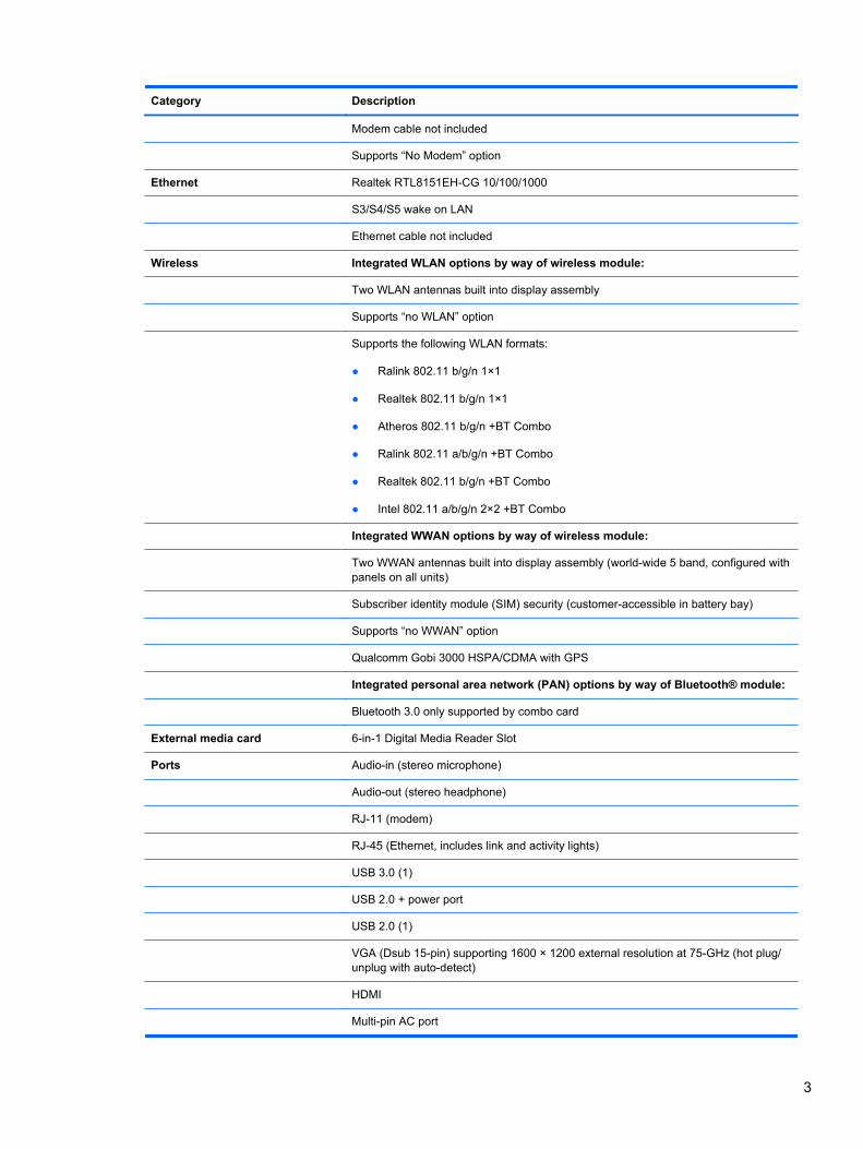
Category Description
Modem cable not included
Supports “No Modem” option
Ethernet Realtek RTL8151EH-CG 10/100/1000
S3/S4/S5 wake on LAN
Ethernet cable not included
Wireless Integrated WLAN options by way of wireless module:
Two WLAN antennas built into display assembly
Supports “no WLAN” option
Supports the following WLAN formats:
● Ralink 802.11 b/g/n 1×1
● Realtek 802.11 b/g/n 1×1
● Atheros 802.11 b/g/n +BT Combo
● Ralink 802.11 a/b/g/n +BT Combo
● Realtek 802.11 b/g/n +BT Combo
● Intel 802.11 a/b/g/n 2×2 +BT Combo
Integrated WWAN options by way of wireless module:
Two WWAN antennas built into display assembly (world-wide 5 band, configured withpanels on all units)
Subscriber identity module (SIM) security (customer-accessible in battery bay)
Supports “no WWAN” option
Qualcomm Gobi 3000 HSPA/CDMA with GPS
Integrated personal area network (PAN) options by way of Bluetooth® module:
Bluetooth 3.0 only supported by combo card
External media card 6-in-1 Digital Media Reader Slot
Ports Audio-in (stereo microphone)
Audio-out (stereo headphone)
RJ-11 (modem)
RJ-45 (Ethernet, includes link and activity lights)
USB 3.0 (1)
USB 2.0 + power port
USB 2.0 (1)
VGA (Dsub 15-pin) supporting 1600 × 1200 external resolution at 75-GHz (hot plug/unplug with auto-detect)
HDMI
Multi-pin AC port
3

Category Description
Keyboard/pointing devices Full-sized keyboard
Touchpad includes: supports 2-way scroll with legend, taps enabled by default, 2-finger scrolling and zoom enabled by default
Power requirements Smart AC adapter with localized cable plug support (3-wire plug with ground pin):
65-W “Smart” AC adapter
65-W “Slim” AC adapter (ABJ and ACF only)
In-line cavity
6-cell, 62-Wh Li-ion battery
4-cell, 41-Wh Li-ion battery
Security Integrated fingerprint reader
Intel AT support
Support Kensington security lock
Trusted Platform Module (TPM) support
Support no fingerprint reader option
Operating system Preinstalled:
Windows 7 Professional 32 with Microsoft® Basics
Windows 7 Professional 64 with Microsoft Basics
Windows 7 Home Premium 64 with Microsoft Basics
Windows 7 Home Premium 32 with Microsoft Basics
Windows Vista Home Basic 32 with Microsoft Basics
Novell™: SuSE Linux™ – SLED 11
FreeDOS
Preinstalled with Microsoft Office:
Windows 7 Professional 32 with Microsoft Office 2010 Starter EDGI
Windows 7 Professional 32 with Microsoft Office 2010 Starter
Windows 7 Professional 32 with Microsoft Office 2010 Personal
Windows 7 Professional 32 with Microsoft Office 2010 Home & Business
Windows 7 Professional 32 with Microsoft Office 2010 Professional
Windows 7 Professional 64 with Microsoft Office 2010 Starter EDGI
Windows 7 Professional 64 with Microsoft Office 2010 Starter
Windows 7 Professional 64 with Microsoft Office 2010 Personal
Windows 7 Professional 64 with Microsoft Office 2010 Home & Business
Windows 7 Professional 64 with Microsoft Office 2010 Professional
Windows 7 Home Premium 32 with Microsoft Office 2010 Starter EDGI
Windows 7 Home Premium 32 with Microsoft Office 2010 Starter
4 Chapter 1 Product description

Category Description
Windows 7 Home Premium 32 with Microsoft Office 2010 Personal
Windows 7 Home Premium 32 with Microsoft Office 2010 Home & Business
Windows 7 Home Premium 32 with Microsoft Office 2010 Professional
Windows 7 Home Premium 64 with Microsoft Office 2010 Starter EDGI
Windows 7 Home Premium 64 with Microsoft Office 2010 Starter
Windows 7 Premium 64 with Microsoft Office 2010 Personal
Windows 7 Premium 64 with Microsoft Office 2010 Home & Business
Windows 7 Premium 64 with Microsoft Office 2010 Professional
Windows 7 Home Basic 32 with Microsoft Office 2010 Starter EDGI
Windows 7 Home Basic 32 with Microsoft Office 2010 Starter
Windows Vista Basic 32 with Microsoft Office 2010 Starter
Windows Vista Basic 32 with Microsoft Office 2010 Personal
Windows Vista Basic 32 with Microsoft Office 2010 Home & Business
Windows Vista Basic 32 with Microsoft Office 2010 Professional
Windows 7 Starter with Office 2010 Starter
Windows 7 Starter with Office 2010 Starter - EDGI
Restore Media:
Windows 7 Professional 64
Windows 7 Professional 32
Windows 7 Home Basic 32
Windows 7 Home Premium 64
Windows 7 Home Premium 32
Windows 7 Starter
DRDVD Windows 7
Windows Vista – through Service only
Web-only support:
Windows XP Professional
Certified:
Microsoft WHQL
Serviceability End-user replaceable parts:
AC adapter
Battery (system)
Hard drive
Memory module
5
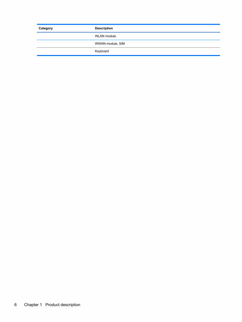
Category Description
WLAN module
WWAN module, SIM
Keyboard
6 Chapter 1 Product description

2 External component identification
Display
Component Description
(1) WWAN antennas (2)* (select models only) Send and receive wireless signals to communicate with wirelesswide-area networks (WWAN).
(2) WLAN antennas (2)* Send and receive wireless signals to communicate with wirelesslocal area networks (WLAN).
(3) Internal microphone(s) (1 or 2 depending onmodel)
Record sound.
(4) Webcam light (select models only) On: The webcam is in use.
Display 7

Component Description
(5) Webcam (select models only) Records video and captures still photographs.
To use the webcam, select Start > All Programs > ArcSoftCamera Suite > WebCam Companion.
*The antennas are not visible from the outside of the computer. For optimal transmission, keep the areas immediatelyaround the antennas free from obstructions. To see wireless regulatory notices, refer to the section of the Regulatory, Safety,and Environmental Notices that applies to your country or region. These notices are located in Help and Support.
Top
TouchPad
Component Description
(1) TouchPad on/off button Turns the TouchPad on and off.
(2) TouchPad Moves the pointer and selects or activates items on thescreen.
(3) Left TouchPad button Functions like the left button on an external mouse.
(4) Right TouchPad button Functions like the right button on an external mouse.
8 Chapter 2 External component identification

Lights
Component Description
(1) Power light ● On: The computer is on.
● Blinking: The computer is in the Sleep state.
● Off: The computer is off or in Hibernation.
(2) QuickWeb light ● On: The computer is on or the default Web browser isin use.
● Blinking: When the QuickWeb button is pressed, thelight blinks 5 times, and then the default Web browseropens.
NOTE: To use HP QuickWeb when the computer is off,HP QuickWeb must be enabled in Computer Setup.
(3) Wireless light ● White: An integrated wireless device, such as awireless local area network (WLAN) device and/or aBluetooth® device, is on.
● Amber: All wireless devices are off.
(4) Caps lock light On: Caps lock is on.
(5) TouchPad light ● Off: The TouchPad is on.
● Amber: The TouchPad is off.
Top 9

Buttons and fingerprint reader (select models only)
Component Description
(1) Power button ● When the computer is off, press the button to turn onthe computer.
● When the computer is on, press the button briefly toinitiate Sleep.
● When the computer is in the Sleep state, press thebutton briefly to exit Sleep.
● When the computer is in Hibernation, press the buttonbriefly to exit Hibernation.
If the computer has stopped responding and Windows®shutdown procedures are ineffective, press and hold thepower button for at least 5 seconds to turn off the computer.
To learn more about your power settings:
● Windows 7—Select Start > Control Panel > Systemand Security > Power Options.
● Windows Vista—Select Start > Control Panel >System and Maintenance > Power Options
● Or refer to the HP Notebook Reference Guide.
10 Chapter 2 External component identification

Component Description
(2) HP QuickWeb light ● When the computer is off or in Hibernation, press thebutton to open HP QuickWeb.
● When the computer is in Microsoft Windows, press thebutton to open the default Web browser.
● When the computer is in HP QuickWeb, press thebutton to open the default Web browser.
NOTE: For more information, refer to “HP QuickWeb” inthis guide and to the HP QuickWeb software Help. If yourcomputer does not have HP QuickWeb software, the buttondoes not perform any action or function.
(3) Wireless button Turns the wireless feature on or off but does not establish awireless connection.
(4) Fingerprint reader (select models only) Allows a fingerprint logon to Windows, instead of apassword logon.
Top 11
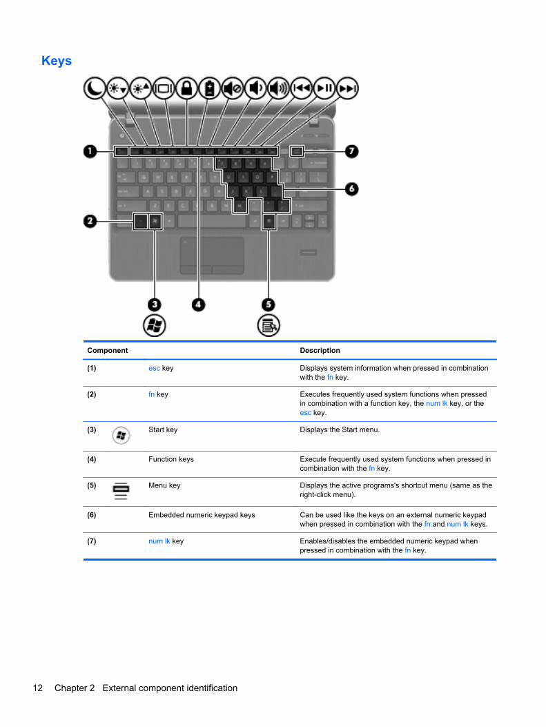
Keys
Component Description
(1) esc key Displays system information when pressed in combinationwith the fn key.
(2) fn key Executes frequently used system functions when pressedin combination with a function key, the num lk key, or theesc key.
(3) Start key Displays the Start menu.
(4) Function keys Execute frequently used system functions when pressed incombination with the fn key.
(5) Menu key Displays the active programs's shortcut menu (same as theright-click menu).
(6) Embedded numeric keypad keys Can be used like the keys on an external numeric keypadwhen pressed in combination with the fn and num lk keys.
(7) num lk key Enables/disables the embedded numeric keypad whenpressed in combination with the fn key.
12 Chapter 2 External component identification

Front
Component Description
(1) Drive light ● Blinking white: The hard drive is being accessed.
● Amber: HP 3D DriveGuard has temporarily parked the harddrive.
(2) Media Card Reader Supports the following digital card formats:
● Memory Stick Pro
● Memory Stick Duo Pro
● MultiMediaCard
● MultiMediaCard Micro
● Secure Digital (SD) Card
● Secure Digital (SD) Card Micro
(3) Speakers (2) Produce sound.
(4) Audio-out (headphone) jack Connects optional headphones, earbuds, a headset, or televisionaudio.
WARNING! To reduce the risk of personal injury, adjust thevolume before putting on headphones, earbuds, or a headset.For additional safety information, refer to the Regulatory, Safety,and Environmental Notices.
NOTE: When a device is connected to the jack, the computerspeakers are disabled.
(5) Audio-in (microphone) jack Connects an optional computer headset microphone, stereoarray microphone, or monaural microphone.
Front 13

Left
Component Description
(1) Security cable slot Attaches an optional security cable to the computer.
NOTE: The security cable is designed to act as adeterrent, but it may not prevent the computer from beingmishandled or stolen.
(2) RJ-11 (modem) jack (select models only) Connects a modem cable.
(3) Vent Enables airflow to cool internal components.
NOTE: The computer fan starts up automatically to coolinternal components and prevent overheating. It is normalfor the internal fan to cycle on and off during routineoperation.
(4) External monitor port Connects an external VGA monitor or projector.
(5)HDMI port Connects an optional video or audio device, such as a
high-definition television, or any compatible digital or audiocomponent.
(6) SuperSpeed 3.0 USB port Connects an optional USB device.
14 Chapter 2 External component identification

Right
Component Description
(1) AC adapter light ● White: The computer is connected to external powerand the battery is 90 to 99% charged.
● Amber: The computer is connected to external powerand the battery is 0 to 90% charged.
● Blinking amber: A battery that is the only availablepower source has reached a low battery level. Whenthe battery reaches a critical battery level, the batterylight begins blinking rapidly.
● Off: The battery is fully charged.
NOTE: If the computer is plugged into an externalpower source, the light turns off when all batteries inthe computer are fully charged. If the computer is notplugged into an external power source, the light staysoff until the battery reaches a low battery level.
(2) USB 2.0 powered/charging port Connects optional USB devices.
(3) USB port Connects optional USB devices.
(4) RJ-45 (network) jack Connects a network cable.
(5) Power connector Connects an AC adapter.
Right 15
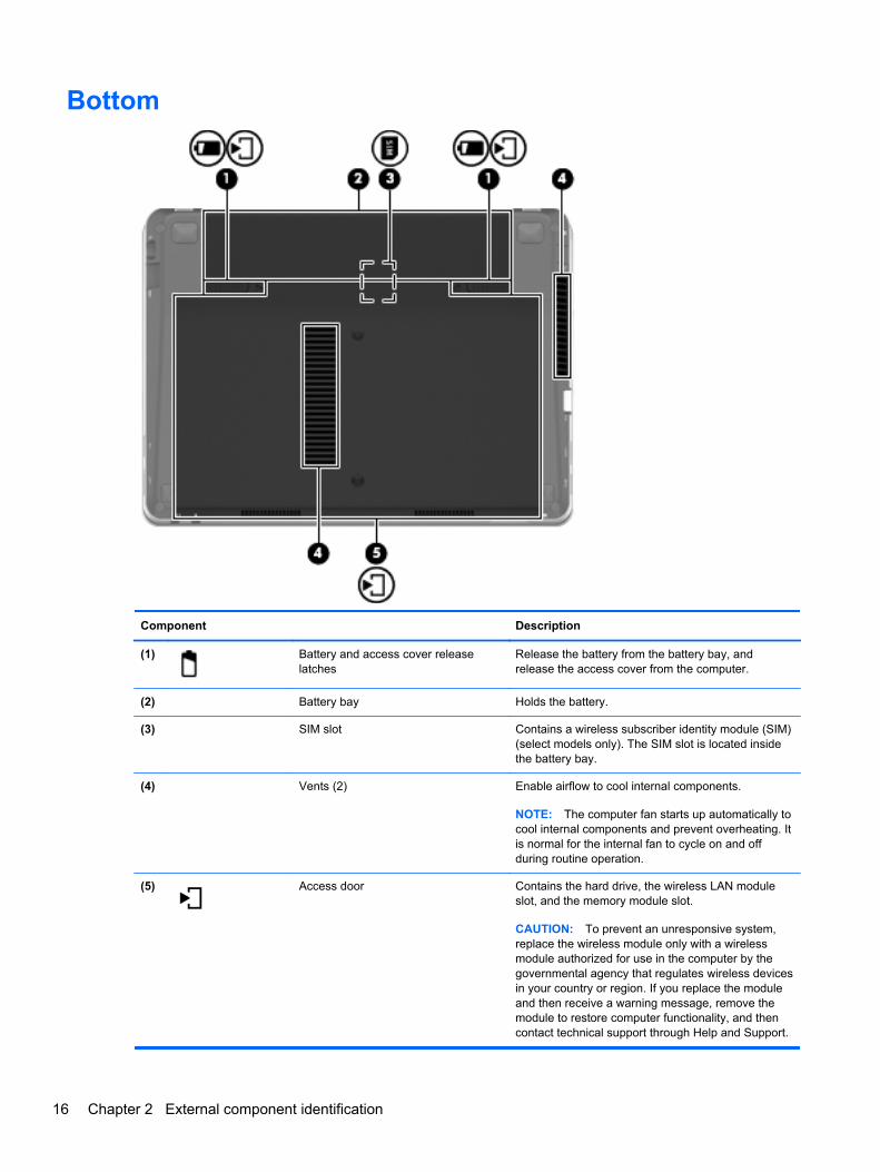
Bottom
Component Description
(1) Battery and access cover releaselatches
Release the battery from the battery bay, andrelease the access cover from the computer.
(2) Battery bay Holds the battery.
(3) SIM slot Contains a wireless subscriber identity module (SIM)(select models only). The SIM slot is located insidethe battery bay.
(4) Vents (2) Enable airflow to cool internal components.
NOTE: The computer fan starts up automatically tocool internal components and prevent overheating. Itis normal for the internal fan to cycle on and offduring routine operation.
(5) Access door Contains the hard drive, the wireless LAN moduleslot, and the memory module slot.
CAUTION: To prevent an unresponsive system,replace the wireless module only with a wirelessmodule authorized for use in the computer by thegovernmental agency that regulates wireless devicesin your country or region. If you replace the moduleand then receive a warning message, remove themodule to restore computer functionality, and thencontact technical support through Help and Support.
16 Chapter 2 External component identification

3 Illustrated parts catalog
Service tagWhen ordering parts or requesting information, provide the computer serial number and modeldescription provided on the service tag.
● Product name (1). This is the product name affixed to the front of the computer.
● Serial number (s/n) (2). This is an alphanumeric identifier that is unique to each product.
● Part number/Product number (p/n) (3). This number provides specific information about theproduct's hardware components. The part number helps a service technician to determine whatcomponents and parts are needed.
● Warranty period (4). This number describes the duration (in years) of the warranty period for thecomputer.
● Model description (5). This is the alphanumeric identifier used to locate documents, drivers, andsupport for the computer.
Service tag 17

Computer major components
Item Description Spare part number
(1) Display panel
30.7-cm (12.1-inch) WXGA, anti-glare 646017-001
30.7-cm (12.1-inch) WXGA, anti-glare with webcam 646019-001
30.7-cm (12.1-inch) WXGA, anti-glare with webcam and WWAN 646021-001
30.7-cm (12.1-inch) WXGA, BrightView 646023-001
30.7-cm (12.1-inch) WXGA, BrightView with webcam 646025-001
(2) Keyboard (includes cable)
NOTE: For a detailed list of available keyboards, see Sequential part number listingon page 28.
646029-xx1
(3) Top cover (includes Touchpad board)
For use in models with USB 3.0 and with a fingerprint reader 646041-001
For use in models with USB 3.0 and without a fingerprint reader 646047-001
18 Chapter 3 Illustrated parts catalog

Item Description Spare part number
With a fingerprint reader slot insert for use in computers that do not support a fingerprintreader
657232-001
For use in computers with USB 2.0 and a fingerprint reader 657960-001
For use in computers with USB 2.0 and without a fingerprint reader 657961-001
With no USB logo for use in USB 2.0 or USB 3.0 computers with a fingerprint reader 666893-001
With no USB logo for use in USB 2.0 or USB 3.0 computers without a fingerprint reader 666894-001
(4) Power button board 647132-001
(5) Quick Launch board 646048-001
(6) Modem module
NOTE: The modem module spare part kit does not include a modem module cable. Themodem module cable is included in the Cable Kit, spare part number 646016-001. SeeCable Kit on page 26 for more Cable Kit spare part number information.
628824-001
(7) Speaker assembly 646038-001
(8) System board (includes replacement thermal material)
For use in models without WWAN 646039-001
For use models with WWAN 646040-001
For use in models with WWAN in Russia and the People's Republic of China 646040-AA1
(9) Fan 646027-001
(10) Heat sink (includes replacement thermal material) 646028-001
(11) Processor
Intel Core i7 processors, Dual Core
2620M, 2.7-GHz (turbo up to 3.4-GHz) processor 4-MB L3 cache 631252-001
Intel Core i5 processors, Dual Core
2540M, 2.6-GHz (turbo up to 3.3-GHz) processor 3-MB L3 cache (includes phase changematerial (PCM))
631255-001
2520M, 2.5-GHz (turbo up to 3.2-GHz) processor 3-MB L3 cache (includes phase changematerial (PCM))
631253-001
2430M, 2.4-GHz (turbo up to 3.0-GHz) processor 3-MB L3 cache 653341-001
2410M, 2.3-GHz (turbo up to 2.9-GHz) processor 3-MB L3 cache 638039-001
Intel Core i3 processors, Dual Core
2350M, 2.3-GHz processor 3-MB L3 cache (includes thermal grease) 653340-001
2330M, 2.2-GHz processor 3-MB L3 cache (includes thermal grease) 653339-001
2310M, 2.1-GHz processor 3-MB L3 cache (includes thermal grease) 638037-001
Intel Pentium Dual-Core processors
B950, 2.1-GHz, with 2-MB L3 cache 653338-001
B940, 2.0-GHz, with 2-MB L3 cache 653337-001
Computer major components 19

Item Description Spare part number
Intel Celeron processors
B840, 1.9-GHz, with 2-MB L3 cache 664663-001
B810, 1.6-GHz, with 2-MB L3 cache 646760-001
(12) WWAN modules
HP un2430 EV-DO/HSPA Mobile Broadband Module 634400-001
HP hs2340 HSPA+ Mobile Broadband Module 632155-001
(13) WLAN modules
Atheros AR9002WB-1NGB 802.11b/g/n 1x1 WiFi and Bluetooth 2.1+EDR Combo Adapterfor use in Afghanistan, Albania, Algeria, Andorra, Angola, Antigua and Barbuda, Argentina,Armenia, Aruba, Australia, Austria, Azerbaijan, Bahamas, Bahrain, Bangladesh, Barbados,Belarus, Belgium, Belize, Benin, Bermuda, Bhutan, Bolivia, Bosnia and Herzegovina,Botswana, Brazil, the British Virgin Islands, Brunei, Bulgaria, Burkina Faso, Burundi,Cambodia, Cameroon, Canada, Cape Verde, the Cayman Islands, Central AfricanRepublic, Chad, Chile, People's Republic of China, Colombia, Comoros, Congo, CostaRica, Croatia, Cyprus, the Czech Republic, Denmark, Djibouti, Dominica, the DominicanRepublic, East Timor, Ecuador, Egypt, El Salvador, Equitorial Guinea, Eritrea, Estonia,Ethiopia, Fiji, Finland, France, French Guiana, Gabon, Gambia, Georgia, Germany, Ghana,Gibraltar, Greece, Grenada, Guadeloupe, Guam, Guatemala, Guinea, Guinea-Bissa,Guyana, Haiti, Honduras, Hong Kong, Hungary, Iceland, India, Indonesia, Ireland, Israel,Italy, Ivory Coast, Jamaica, Japan, Jordan, Kazakhstan, Kenya, Kiribati, Kuwait,Kyrgyzstan, Laos, Latvia, Lebanon, Lesotho, Liberia, Liechtenstein, Lithuania, Luxembourg,Macedonia, Madagascar, Malawi, Malaysia, Maldives, Mali, Malta, Marshall Islands,Martinique, Mauritania, Mauritius, Mexico, Micronesia, Monaco, Mongolia, Montenegro,Morocco, Mozambique, Namibia, Nauru, Nepal, the Nether Antilles, the Netherlands, NewZealand, Nicaragua, Niger, Nigeria, Norway, Oman, Pakistan, Palau, Panama, Papua NewGuinea, Paraguay, Puerto Rico, Peru, Philippines, Poland, Portugal, Qatar, Republic ofMoldova, Romania, Russia, Rwanda, Samoa, San Marino, Sao Tome and Principe, SaudiArabia, Senegal, Serbia and Montenegro, Seychelles, Sierra Leone, Singapore, Slovakia,Slovenia, Solomon Islands, Somalia, South Africa, South Korea, Spain, Sri Lanka, St. Kittsand Nevis, St. Lucia, St. Vincent and the Grenadines, Suriname, Swaziland, Sweden,Switzerland, Syria, Taiwan, Tajikistan, Tanzania, Thailand, Togo, Tonga, Trinidad andTobago, Tunisia, Turkey, Turkmenistan, Tuvalu, Uganda, Ukraine, the United ArabEmirates, the United Kingdom, Uruguay, the United States, the US Virgin Islands,Uzbekistan, Vanuatu, Venezuela, Vietnam, Yemen, Zaire, Zambia, and Zimbabwe
593127-001
20 Chapter 3 Illustrated parts catalog

Item Description Spare part number
Realtek 8188BC8 802.11a/b/g/n 2x2 WiFi and Bluetooth 3.0+HS Combo Adapter for use inAfghanistan, Albania, Algeria, Andorra, Angola, Antigua and Barbuda, Argentina, Armenia,Aruba, Australia, Austria, Azerbaijan, Bahamas, Bahrain, Baltics, Bangladesh, Barbados,Belarus, Belgium, Belize, Benin, Bermuda, Bhutan, Bolivia, Bosnia and Herzegovina,Botswana, Brazil, the British Virgin Islands, Brunei, Bulgaria, Burkina Faso, Burundi,Cambodia, Cameroon, Canada, Cape Verde, the Cayman Islands, Central AfricanRepublic, Chad, Chile, People's Republic of China, Colombia, Comoros, Congo, CostaRica, Croatia, Cyprus, the Czech Republic, Denmark, Djibouti, Dominica, the DominicanRepublic, East Timor, Ecuador, Egypt, El Salvador, Equitorial Guinea, Eritrea, Estonia,Ethiopia, Fiji, Finland, France, French Guiana, Gabon, Gambia, Georgia, Germany, Ghana,Gibraltar, Greece, Grenada, Guadeloupe, Guam, Guatemala, Guinea, Guinea-Bissa,Guyana, Haiti, Honduras, Hong Kong, Hungary, Iceland, India, Indonesia, Iraq, Ireland,Israel, Italy, Ivory Coast, Jamaica, Japan, Jordan, Kazakhstan, Kenya, Kiribati, Kuwait,Kyrgyzstan, Laos, Latvia, Lebanon, Lesotho, Liberia, Liechtenstein, Lithuania, Luxembourg,Macedonia, Madagascar, Malawi, Malaysia, Maldives, Mali, Malta, Marshall Islands,Martinique, Mauritania, Mauritius, Mexico, Micronesia, Monaco, Mongolia, Montenegro,Morocco, Mozambique, Namibia, Nauru, Nepal, the Nether Antilles, the Netherlands, NewZealand, Nicaragua, Niger, Nigeria, Norway, Oman, Pakistan, Palau, Panama, Papua NewGuinea, Paraguay, Puerto Rico, Peru, Philippines, Poland, Portugal, Qatar, Republic ofMoldova, Romania, Russia, Rwanda, Samoa, San Marino, Sao Tome and Principe, SaudiArabia, Senegal, Serbia and Montenegro, Seychelles, Sierra Leone, Singapore, Slovakia,Slovenia, Solomon Islands, Somalia, South Africa, South Korea, Spain, Sri Lanka, St. Kittsand Nevis, St. Lucia, St. Vincent and the Grenadines, Suriname, Swaziland, Sweden,Switzerland, Syria, Taiwan, Tajikistan, Tanzania, Thailand, Togo, Tonga, Trinidad andTobago, Tunisia, Turkey, Turkmenistan, Tuvalu, Uganda, Ukraine, the United ArabEmirates, the United Kingdom, Uruguay, the United States, the US Virgin Islands,Uzbekistan, Vanuatu, Venezuela, Vietnam, Yemen, Zaire, Zambia, and Zimbabwe
602993-001
Ralink 5390GN 802.11b/g/n 1x1 WiFi Adapter for use in Afghanistan, Albania, Algeria,Andorra, Angola, Antigua and Barbuda, Argentina, Armenia, Aruba, Australia, Austria,Azerbaijan, Bahamas, Bahrain, Baltics, Bangladesh, Barbados, Belarus, Belgium, Belize,Benin, Bermuda, Bhutan, Bolivia, Bosnia and Herzegovina, Botswana, Brazil, the BritishVirgin Islands, Brunei, Bulgaria, Burkina Faso, Burundi, Cambodia, Cameroon, Canada,Cape Verde, the Cayman Islands, Central African Republic, Chad, Chile, People's Republicof China, Colombia, Comoros, Congo, Costa Rica, Croatia, Cyprus, the Czech Republic,Denmark, Djibouti, Dominica, the Dominican Republic, East Timor, Ecuador, Egypt, ElSalvador, Equitorial Guinea, Eritrea, Estonia, Ethiopia, Fiji, Finland, France, FrenchGuiana, Gabon, Gambia, Georgia, Germany, Ghana, Gibraltar, Greece, Grenada,Guadeloupe, Guam, Guatemala, Guinea, Guinea-Bissa, Guyana, Haiti, Honduras, HongKong, Hungary, Iceland, India, Indonesia, Iraq, Ireland, Israel, Italy, Ivory Coast, Jamaica,Japan, Jordan, Kazakhstan, Kenya, Kiribati, Kuwait, Kyrgyzstan, Laos, Latvia, Lebanon,Lesotho, Liberia, Liechtenstein, Lithuania, Luxembourg, Macedonia, Madagascar, Malawi,Malaysia, Maldives, Mali, Malta, Marshall Islands, Martinique, Mauritania, Mauritius,Mexico, Micronesia, Monaco, Mongolia, Montenegro, Morocco, Mozambique, Namibia,Nauru, Nepal, the Nether Antilles, the Netherlands, New Zealand, Nicaragua, Niger,Nigeria, Norway, Oman, Pakistan, Palau, Panama, Papua New Guinea, Paraguay, PuertoRico, Peru, Philippines, Poland, Portugal, Qatar, Republic of Moldova, Romania, Russia,Rwanda, Samoa, San Marino, Sao Tome and Principe, Saudi Arabia, Senegal, Serbia andMontenegro, Seychelles, Sierra Leone, Singapore, Slovakia, Slovenia, Solomon Islands,Somalia, South Africa, South Korea, Spain, Sri Lanka, St. Kitts and Nevis, St. Lucia, St.Vincent and the Grenadines, Suriname, Swaziland, Sweden, Switzerland, Syria, Taiwan,Tajikistan, Tanzania, Thailand, Togo, Tonga, Trinidad and Tobago, Tunisia, Turkey,Turkmenistan, Tuvalu, Uganda, Ukraine, the United Arab Emirates, the United Kingdom,Uruguay, the United States, the US Virgin Islands, Uzbekistan, Vanuatu, Venezuela,Vietnam, Yemen, Zaire, Zambia, and Zimbabwe
630703-001
Computer major components 21
Item Description Spare part number
Ralink 8190BC8 802.11b/g/n 2x2 WiFi and Bluetooth 3.0+HS Combo Adapter for use inAfghanistan, Albania, Algeria, Andorra, Angola, Antigua and Barbuda, Argentina, Armenia,Aruba, Australia, Austria, Azerbaijan, Bahamas, Bahrain, Baltics, Bangladesh, Barbados,Belarus, Belgium, Belize, Benin, Bermuda, Bhutan, Bolivia, Bosnia and Herzegovina,Botswana, Brazil, the British Virgin Islands, Brunei, Bulgaria, Burkina Faso, Burundi,Cambodia, Cameroon, Canada, Cape Verde, the Cayman Islands, Central AfricanRepublic, Chad, Chile, People's Republic of China, Colombia, Comoros, Congo, CostaRica, Croatia, Cyprus, the Czech Republic, Denmark, Djibouti, Dominica, the DominicanRepublic, East Timor, Ecuador, Egypt, El Salvador, Equitorial Guinea, Eritrea, Estonia,Ethiopia, Fiji, Finland, France, French Guiana, Gabon, Gambia, Georgia, Germany, Ghana,Gibraltar, Greece, Grenada, Guadeloupe, Guam, Guatemala, Guinea, Guinea-Bissa,Guyana, Haiti, Honduras, Hong Kong, Hungary, Iceland, India, Indonesia, Iraq, Ireland,Israel, Italy, Ivory Coast, Jamaica, Japan, Jordan, Kazakhstan, Kenya, Kiribati, Kuwait,Kyrgyzstan, Laos, Latvia, Lebanon, Lesotho, Liberia, Liechtenstein, Lithuania, Luxembourg,Macedonia, Madagascar, Malawi, Malaysia, Maldives, Mali, Malta, Marshall Islands,Martinique, Mauritania, Mauritius, Mexico, Micronesia, Monaco, Mongolia, Montenegro,Morocco, Mozambique, Namibia, Nauru, Nepal, the Nether Antilles, the Netherlands, NewZealand, Nicaragua, Niger, Nigeria, Norway, Oman, Pakistan, Palau, Panama, Papua NewGuinea, Paraguay, Puerto Rico, Peru, Philippines, Poland, Portugal, Qatar, Republic ofMoldova, Romania, Russia, Rwanda, Samoa, San Marino, Sao Tome and Principe, SaudiArabia, Senegal, Serbia and Montenegro, Seychelles, Sierra Leone, Singapore, Slovakia,Slovenia, Solomon Islands, Somalia, South Africa, South Korea, Spain, Sri Lanka, St. Kittsand Nevis, St. Lucia, St. Vincent and the Grenadines, Suriname, Swaziland, Sweden,Switzerland, Syria, Taiwan, Tajikistan, Tanzania, Thailand, Togo, Tonga, Trinidad andTobago, Tunisia, Turkey, Turkmenistan, Tuvalu, Uganda, Ukraine, the United ArabEmirates, the United Kingdom, Uruguay, the United States, the US Virgin Islands,Uzbekistan, Vanuatu, Venezuela, Vietnam, Yemen, Zaire, Zambia, and Zimbabwe
630813-001
Realtek 8188GN 802.11b/g/n 1x1 WiFi Adapter for use in Afghanistan, Albania, Algeria,Andorra, Angola, Antigua and Barbuda, Argentina, Armenia, Aruba, Australia, Austria,Azerbaijan, Bahamas, Bahrain, Baltics, Bangladesh, Barbados, Belarus, Belgium, Belize,Benin, Bermuda, Bhutan, Bolivia, Bosnia and Herzegovina, Botswana, Brazil, the BritishVirgin Islands, Brunei, Bulgaria, Burkina Faso, Burundi, Cambodia, Cameroon, Canada,Cape Verde, the Cayman Islands, Central African Republic, Chad, Chile, People's Republicof China, Colombia, Comoros, Congo, Costa Rica, Croatia, Cyprus, the Czech Republic,Denmark, Djibouti, Dominica, the Dominican Republic, East Timor, Ecuador, Egypt, ElSalvador, Equitorial Guinea, Eritrea, Estonia, Ethiopia, Fiji, Finland, France, FrenchGuiana, Gabon, Gambia, Georgia, Germany, Ghana, Gibraltar, Greece, Grenada,Guadeloupe, Guam, Guatemala, Guinea, Guinea-Bissa, Guyana, Haiti, Honduras, HongKong, Hungary, Iceland, India, Indonesia, Iraq, Ireland, Israel, Italy, Ivory Coast, Jamaica,Japan, Jordan, Kazakhstan, Kenya, Kiribati, Kuwait, Kyrgyzstan, Laos, Latvia, Lebanon,Lesotho, Liberia, Liechtenstein, Lithuania, Luxembourg, Macedonia, Madagascar, Malawi,Malaysia, Maldives, Mali, Malta, Marshall Islands, Martinique, Mauritania, Mauritius,Mexico, Micronesia, Monaco, Mongolia, Montenegro, Morocco, Mozambique, Namibia,Nauru, Nepal, the Nether Antilles, the Netherlands, New Zealand, Nicaragua, Niger,Nigeria, Norway, Oman, Pakistan, Palau, Panama, Papua New Guinea, Paraguay, PuertoRico, Peru, Philippines, Poland, Portugal, Qatar, Republic of Moldova, Romania, Russia,Rwanda, Samoa, San Marino, Sao Tome and Principe, Saudi Arabia, Senegal, Serbia andMontenegro, Seychelles, Sierra Leone, Singapore, Slovakia, Slovenia, Solomon Islands,Somalia, South Africa, South Korea, Spain, Sri Lanka, St. Kitts and Nevis, St. Lucia, St.Vincent and the Grenadines, Suriname, Swaziland, Sweden, Switzerland, Syria, Taiwan,Tajikistan, Tanzania, Thailand, Togo, Tonga, Trinidad and Tobago, Tunisia, Turkey,Turkmenistan, Tuvalu, Uganda, Ukraine, the United Arab Emirates, the United Kingdom,Uruguay, the United States, the US Virgin Islands, Uzbekistan, Vanuatu, Venezuela,Vietnam, Yemen, Zaire, Zambia, and Zimbabwe
640926-001
22 Chapter 3 Illustrated parts catalog

Item Description Spare part number
Intel Centrino® Advanced-N 6230 for use in Afghanistan, Albania, Algeria, Andorra,Angola, Antigua and Barbuda, Argentina, Armenia, Aruba, Australia, Austria, Azerbaijan,Bahamas, Bahrain, Baltics, Bangladesh, Barbados, Belarus, Belgium, Belize, Benin,Bermuda, Bhutan, Bolivia, Bosnia and Herzegovina, Botswana, Brazil, the British VirginIslands, Brunei, Bulgaria, Burkina Faso, Burundi, Cambodia, Cameroon, Canada, CapeVerde, the Cayman Islands, Central African Republic, Chad, Chile, People's Republic ofChina, Colombia, Comoros, Congo, Costa Rica, Croatia, Cyprus, the Czech Republic,Denmark, Djibouti, Dominica, the Dominican Republic, East Timor, Ecuador, Egypt, ElSalvador, Equitorial Guinea, Eritrea, Estonia, Ethiopia, Fiji, Finland, France, FrenchGuiana, Gabon, Gambia, Georgia, Germany, Ghana, Gibraltar, Greece, Grenada,Guadeloupe, Guam, Guatemala, Guinea, Guinea-Bissa, Guyana, Haiti, Honduras, HongKong, Hungary, Iceland, India, Indonesia, Iraq, Ireland, Israel, Italy, Ivory Coast, Jamaica,Japan, Jordan, Kazakhstan, Kenya, Kiribati, Kuwait, Kyrgyzstan, Laos, Latvia, Lebanon,Lesotho, Liberia, Liechtenstein, Lithuania, Luxembourg, Macedonia, Madagascar, Malawi,Malaysia, Maldives, Mali, Malta, Marshall Islands, Martinique, Mauritania, Mauritius,Mexico, Micronesia, Monaco, Mongolia, Montenegro, Morocco, Mozambique, Namibia,Nauru, Nepal, the Nether Antilles, the Netherlands, New Zealand, Nicaragua, Niger,Nigeria, Norway, Oman, Pakistan, Palau, Panama, Papua New Guinea, Paraguay, PuertoRico, Peru, Philippines, Poland, Portugal, Qatar, Republic of Moldova, Romania, Russia,Rwanda, Samoa, San Marino, Sao Tome and Principe, Saudi Arabia, Senegal, Serbia andMontenegro, Seychelles, Sierra Leone, Singapore, Slovakia, Slovenia, Solomon Islands,Somalia, South Africa, South Korea, Spain, Sri Lanka, St. Kitts and Nevis, St. Lucia, St.Vincent and the Grenadines, Suriname, Swaziland, Sweden, Switzerland, Syria, Taiwan,Tajikistan, Tanzania, Thailand, Togo, Tonga, Trinidad and Tobago, Tunisia, Turkey,Turkmenistan, Tuvalu, Uganda, Ukraine, the United Arab Emirates, the United Kingdom,Uruguay, the United States, the US Virgin Islands, Uzbekistan, Vanuatu, Venezuela,Vietnam, Yemen, Zaire, Zambia, and Zimbabwe
636672-001
(14) Hard drive
750-GB, 7200-rpm 633252-001
640-GB, 5400-rpm 603785-001
500-GB, 7200-rpm 634926-001
500-GB, 5400-rpm 634638-001
320-GB, 5400-rpm 645193-001
320-GB, 7200-rpm 634862-001
250-GB, 7200-rpm 634861-001
250-GB, 5400-rpm 645191-001
(15) RTC battery 650924-001
(16) Memory modules (PC3-10600, 1333-MHz, DDR3)
Before adding new memory, make sure you update the computer to the latest BIOS.
CAUTION: Failure to update the computer to the latest BIOS prior to installing new memory may result in varioussystem problems.
4-GB 621569-001
2-GB 621565-001
1-GB 639736-001
(17) Battery, Li-ion
6-cell (62 WHr, 2.8 Ah) 633803-001
Computer major components 23

Item Description Spare part number
6-cell, 55 WHr, 2.8 Ah Li-ion battery 660151-001
4-cell (41 WHr, 2.8 Ah) 633801-001
(18) Base enclosure 646013-001
(19) Access door 646049-001
Display components
Item Description Spare part number
(1) Display bezel
For use on models with a webcam 646014-001
For use on models without a webcam 646015-001
(2) Display hinge cover 646043-001
(3) Display hinge/bracket kit (includes left and right hinges and brackets) 646042-001
(4) Webcam module 642795-001
Microphone module (not illustrated) 642797-001
(5) Display Cable Kit (includes integrated webcam cable) 646044-001
(6) WLAN antennas 646010-001
(7) WWAN antennas 646011-001
24 Chapter 3 Illustrated parts catalog
Item Description Spare part number
(8) Display enclosure 646012-001
Bracket Kit (includes RJ-11 bracket and power bracket; not illustrated) 646045-001
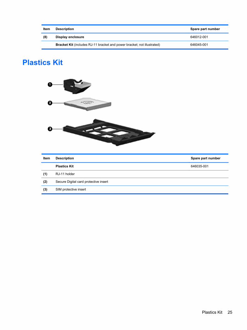
Plastics Kit
Item Description Spare part number
Plastics Kit 646035-001
(1) RJ-11 holder
(2) Secure Digital card protective insert
(3) SIM protective insert
Plastics Kit 25

Cable Kit
Item Description Spare part number
Cable Kit 646016-001
(1) Hard drive cable
(2) RJ-11 connector cable
Mass storage devices
Description Spare part number
Hard drives
750-GB, 7200-rpm 633252-001
640-GB, 5400-rpm 603785-001
500-GB, 7200-rpm 634926-001
500-GB, 5400-rpm 634638-001
320-GB, 5400-rpm 645193-001
320-GB, 7200-rpm 634862-001
250-GB, 7200-rpm 634861-001
250-GB, 5400-rpm 645191-001
Hard Drive Hardware Kit (includes hard drive bracket, insulator, and screws) 646046-001
External DVD±RW and CD-RW DL Combo Drive 602041-001
26 Chapter 3 Illustrated parts catalog

Miscellaneous parts
Description Spare part number
AC adapters
65-W AC adapter 609939-001
65-W AC adapter for use in India 609948-001
65-W travel adapter 592814-001
Power cords:
For use in Australia and New Zealand 490371-011
For use in the People's Republic of China 490371-AA1
For use in Europe, the Middle East, and Africa 490371-021
For use in India 490371-D61
For use in South Korea 490371-AD1
For use in Taiwan 490371-AB1
For use in the United Kingdom 490371-031
For use in the United States 490371-001
Rubber Kit (includes bottom feet) 646036-001
Screw Kit 646037-001
Power cable, 65-W 414135-001
Adapter, plug head for use in the Asia/Pacific region 601451-371
Adapter, USB power 619240-001
HP keyed cable lock 626729-001
Mouse, optical, 2-button 390632-001
HP optical travel mouse 434594-001
HP basic carrying case 455084-001
Professional slim, top load case 592923-001
Notebook combination lock 591699-001
Nylon case 612757-001
Miscellaneous parts 27

Sequential part number listing
Spare partnumber
Description
390632-001 Mouse, optical, 2-button
414135-001 Power cable, 65-W
434594-001 HP optical travel mouse
455084-001 HP basic carrying case
490371-001 Power cord for use in North America
490371-011 Power cord for use in Australia and New Zealand
490371-021 Power cord for use in Europe, the Middle East, and Africa
490371-031 Power cord for use in the United Kingdom
490371-291 Power cord for use in Japan
490371-AA1 Power cord for use in the People's Republic of China
490371-AB1 Power cord for use in Taiwan
490371-AD1 Power cord for use in South Korea
490371-D61 Power cord for use in India
591699-001 Notebook combination lock
592814-001 65-W travel adapter
592923-001 Professional slim, top load case
593127-001 Atheros AR9002WB-1NGB 802.11b/g/n 1x1 WiFi and Bluetooth 2.1+EDR Combo Adapter for use inAfghanistan, Albania, Algeria, Andorra, Angola, Antigua and Barbuda, Argentina, Armenia, Aruba,Australia, Austria, Azerbaijan, Bahamas, Bahrain, Bangladesh, Barbados, Belarus, Belgium, Belize, Benin,Bermuda, Bhutan, Bolivia, Bosnia and Herzegovina, Botswana, Brazil, the British Virgin Islands, Brunei,Bulgaria, Burkina Faso, Burundi, Cambodia, Cameroon, Canada, Cape Verde, the Cayman Islands, CentralAfrican Republic, Chad, Chile, People's Republic of China, Colombia, Comoros, Congo, Costa Rica,Croatia, Cyprus, the Czech Republic, Denmark, Djibouti, Dominica, the Dominican Republic, East Timor,Ecuador, Egypt, El Salvador, Equitorial Guinea, Eritrea, Estonia, Ethiopia, Fiji, Finland, France, FrenchGuiana, Gabon, Gambia, Georgia, Germany, Ghana, Gibraltar, Greece, Grenada, Guadeloupe, Guam,Guatemala, Guinea, Guinea-Bissa, Guyana, Haiti, Honduras, Hong Kong, Hungary, Iceland, India,Indonesia, Ireland, Israel, Italy, Ivory Coast, Jamaica, Japan, Jordan, Kazakhstan, Kenya, Kiribati, Kuwait,Kyrgyzstan, Laos, Latvia, Lebanon, Lesotho, Liberia, Liechtenstein, Lithuania, Luxembourg, Macedonia,Madagascar, Malawi, Malaysia, Maldives, Mali, Malta, Marshall Islands, Martinique, Mauritania, Mauritius,Mexico, Micronesia, Monaco, Mongolia, Montenegro, Morocco, Mozambique, Namibia, Nauru, Nepal, theNether Antilles, the Netherlands, New Zealand, Nicaragua, Niger, Nigeria, Norway, Oman, Pakistan, Palau,Panama, Papua New Guinea, Paraguay, Puerto Rico, Peru, Philippines, Poland, Portugal, Qatar, Republicof Moldova, Romania, Russia, Rwanda, Samoa, San Marino, Sao Tome and Principe, Saudi Arabia,Senegal, Serbia and Montenegro, Seychelles, Sierra Leone, Singapore, Slovakia, Slovenia, SolomonIslands, Somalia, South Africa, South Korea, Spain, Sri Lanka, St. Kitts and Nevis, St. Lucia, St. Vincentand the Grenadines, Suriname, Swaziland, Sweden, Switzerland, Syria, Taiwan, Tajikistan, Tanzania,Thailand, Togo, Tonga, Trinidad and Tobago, Tunisia, Turkey, Turkmenistan, Tuvalu, Uganda, Ukraine, theUnited Arab Emirates, the United Kingdom, Uruguay, the United States, the US Virgin Islands, Uzbekistan,Vanuatu, Venezuela, Vietnam, Yemen, Zaire, Zambia, and Zimbabwe
601451-371 Adapter, plug head for use in the Asia/Pacific region
602041-001 External DVD±RW and CD-RW DL Combo Drive
28 Chapter 3 Illustrated parts catalog
Spare partnumber
Description
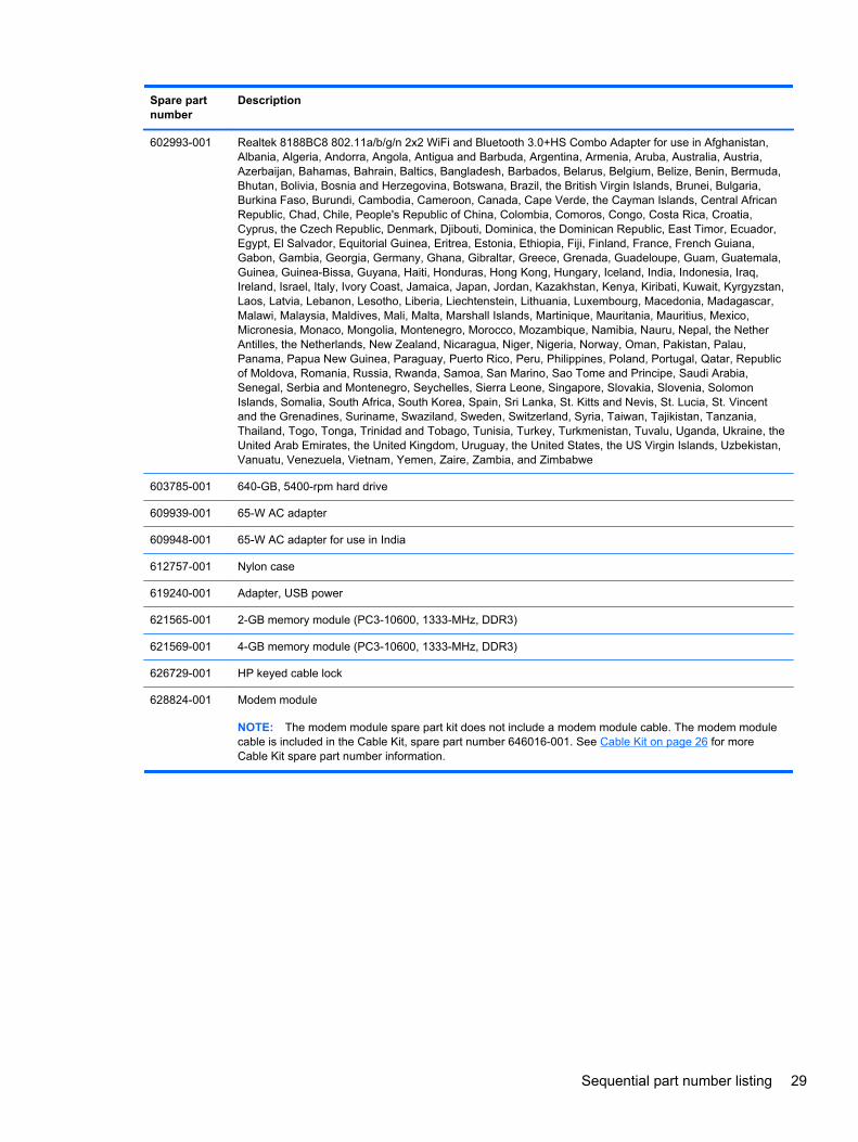
602993-001 Realtek 8188BC8 802.11a/b/g/n 2x2 WiFi and Bluetooth 3.0+HS Combo Adapter for use in Afghanistan,Albania, Algeria, Andorra, Angola, Antigua and Barbuda, Argentina, Armenia, Aruba, Australia, Austria,Azerbaijan, Bahamas, Bahrain, Baltics, Bangladesh, Barbados, Belarus, Belgium, Belize, Benin, Bermuda,Bhutan, Bolivia, Bosnia and Herzegovina, Botswana, Brazil, the British Virgin Islands, Brunei, Bulgaria,Burkina Faso, Burundi, Cambodia, Cameroon, Canada, Cape Verde, the Cayman Islands, Central AfricanRepublic, Chad, Chile, People's Republic of China, Colombia, Comoros, Congo, Costa Rica, Croatia,Cyprus, the Czech Republic, Denmark, Djibouti, Dominica, the Dominican Republic, East Timor, Ecuador,Egypt, El Salvador, Equitorial Guinea, Eritrea, Estonia, Ethiopia, Fiji, Finland, France, French Guiana,Gabon, Gambia, Georgia, Germany, Ghana, Gibraltar, Greece, Grenada, Guadeloupe, Guam, Guatemala,Guinea, Guinea-Bissa, Guyana, Haiti, Honduras, Hong Kong, Hungary, Iceland, India, Indonesia, Iraq,Ireland, Israel, Italy, Ivory Coast, Jamaica, Japan, Jordan, Kazakhstan, Kenya, Kiribati, Kuwait, Kyrgyzstan,Laos, Latvia, Lebanon, Lesotho, Liberia, Liechtenstein, Lithuania, Luxembourg, Macedonia, Madagascar,Malawi, Malaysia, Maldives, Mali, Malta, Marshall Islands, Martinique, Mauritania, Mauritius, Mexico,Micronesia, Monaco, Mongolia, Montenegro, Morocco, Mozambique, Namibia, Nauru, Nepal, the NetherAntilles, the Netherlands, New Zealand, Nicaragua, Niger, Nigeria, Norway, Oman, Pakistan, Palau,Panama, Papua New Guinea, Paraguay, Puerto Rico, Peru, Philippines, Poland, Portugal, Qatar, Republicof Moldova, Romania, Russia, Rwanda, Samoa, San Marino, Sao Tome and Principe, Saudi Arabia,Senegal, Serbia and Montenegro, Seychelles, Sierra Leone, Singapore, Slovakia, Slovenia, SolomonIslands, Somalia, South Africa, South Korea, Spain, Sri Lanka, St. Kitts and Nevis, St. Lucia, St. Vincentand the Grenadines, Suriname, Swaziland, Sweden, Switzerland, Syria, Taiwan, Tajikistan, Tanzania,Thailand, Togo, Tonga, Trinidad and Tobago, Tunisia, Turkey, Turkmenistan, Tuvalu, Uganda, Ukraine, theUnited Arab Emirates, the United Kingdom, Uruguay, the United States, the US Virgin Islands, Uzbekistan,Vanuatu, Venezuela, Vietnam, Yemen, Zaire, Zambia, and Zimbabwe
603785-001 640-GB, 5400-rpm hard drive
609939-001 65-W AC adapter
609948-001 65-W AC adapter for use in India
612757-001 Nylon case
619240-001 Adapter, USB power
621565-001 2-GB memory module (PC3-10600, 1333-MHz, DDR3)
621569-001 4-GB memory module (PC3-10600, 1333-MHz, DDR3)
626729-001 HP keyed cable lock
628824-001 Modem module
NOTE: The modem module spare part kit does not include a modem module cable. The modem modulecable is included in the Cable Kit, spare part number 646016-001. See Cable Kit on page 26 for moreCable Kit spare part number information.
Sequential part number listing 29

Spare partnumber
Description
630703-001 Ralink 5390GN 802.11b/g/n 1x1 WiFi Adapter for use in Afghanistan, Albania, Algeria, Andorra, Angola,Antigua and Barbuda, Argentina, Armenia, Aruba, Australia, Austria, Azerbaijan, Bahamas, Bahrain,Baltics, Bangladesh, Barbados, Belarus, Belgium, Belize, Benin, Bermuda, Bhutan, Bolivia, Bosnia andHerzegovina, Botswana, Brazil, the British Virgin Islands, Brunei, Bulgaria, Burkina Faso, Burundi,Cambodia, Cameroon, Canada, Cape Verde, the Cayman Islands, Central African Republic, Chad, Chile,People's Republic of China, Colombia, Comoros, Congo, Costa Rica, Croatia, Cyprus, the Czech Republic,Denmark, Djibouti, Dominica, the Dominican Republic, East Timor, Ecuador, Egypt, El Salvador, EquitorialGuinea, Eritrea, Estonia, Ethiopia, Fiji, Finland, France, French Guiana, Gabon, Gambia, Georgia,Germany, Ghana, Gibraltar, Greece, Grenada, Guadeloupe, Guam, Guatemala, Guinea, Guinea-Bissa,Guyana, Haiti, Honduras, Hong Kong, Hungary, Iceland, India, Indonesia, Iraq, Ireland, Israel, Italy, IvoryCoast, Jamaica, Japan, Jordan, Kazakhstan, Kenya, Kiribati, Kuwait, Kyrgyzstan, Laos, Latvia, Lebanon,Lesotho, Liberia, Liechtenstein, Lithuania, Luxembourg, Macedonia, Madagascar, Malawi, Malaysia,Maldives, Mali, Malta, Marshall Islands, Martinique, Mauritania, Mauritius, Mexico, Micronesia, Monaco,Mongolia, Montenegro, Morocco, Mozambique, Namibia, Nauru, Nepal, the Nether Antilles, theNetherlands, New Zealand, Nicaragua, Niger, Nigeria, Norway, Oman, Pakistan, Palau, Panama, PapuaNew Guinea, Paraguay, Puerto Rico, Peru, Philippines, Poland, Portugal, Qatar, Republic of Moldova,Romania, Russia, Rwanda, Samoa, San Marino, Sao Tome and Principe, Saudi Arabia, Senegal, Serbiaand Montenegro, Seychelles, Sierra Leone, Singapore, Slovakia, Slovenia, Solomon Islands, Somalia,South Africa, South Korea, Spain, Sri Lanka, St. Kitts and Nevis, St. Lucia, St. Vincent and the Grenadines,Suriname, Swaziland, Sweden, Switzerland, Syria, Taiwan, Tajikistan, Tanzania, Thailand, Togo, Tonga,Trinidad and Tobago, Tunisia, Turkey, Turkmenistan, Tuvalu, Uganda, Ukraine, the United Arab Emirates,the United Kingdom, Uruguay, the United States, the US Virgin Islands, Uzbekistan, Vanuatu, Venezuela,Vietnam, Yemen, Zaire, Zambia, and Zimbabwe
630813-001 Ralink 8190BC8 802.11b/g/n 2x2 WiFi and Bluetooth 3.0+HS Combo Adapter for use in Afghanistan,Albania, Algeria, Andorra, Angola, Antigua and Barbuda, Argentina, Armenia, Aruba, Australia, Austria,Azerbaijan, Bahamas, Bahrain, Baltics, Bangladesh, Barbados, Belarus, Belgium, Belize, Benin, Bermuda,Bhutan, Bolivia, Bosnia and Herzegovina, Botswana, Brazil, the British Virgin Islands, Brunei, Bulgaria,Burkina Faso, Burundi, Cambodia, Cameroon, Canada, Cape Verde, the Cayman Islands, Central AfricanRepublic, Chad, Chile, People's Republic of China, Colombia, Comoros, Congo, Costa Rica, Croatia,Cyprus, the Czech Republic, Denmark, Djibouti, Dominica, the Dominican Republic, East Timor, Ecuador,Egypt, El Salvador, Equitorial Guinea, Eritrea, Estonia, Ethiopia, Fiji, Finland, France, French Guiana,Gabon, Gambia, Georgia, Germany, Ghana, Gibraltar, Greece, Grenada, Guadeloupe, Guam, Guatemala,Guinea, Guinea-Bissa, Guyana, Haiti, Honduras, Hong Kong, Hungary, Iceland, India, Indonesia, Iraq,Ireland, Israel, Italy, Ivory Coast, Jamaica, Japan, Jordan, Kazakhstan, Kenya, Kiribati, Kuwait, Kyrgyzstan,Laos, Latvia, Lebanon, Lesotho, Liberia, Liechtenstein, Lithuania, Luxembourg, Macedonia, Madagascar,Malawi, Malaysia, Maldives, Mali, Malta, Marshall Islands, Martinique, Mauritania, Mauritius, Mexico,Micronesia, Monaco, Mongolia, Montenegro, Morocco, Mozambique, Namibia, Nauru, Nepal, the NetherAntilles, the Netherlands, New Zealand, Nicaragua, Niger, Nigeria, Norway, Oman, Pakistan, Palau,Panama, Papua New Guinea, Paraguay, Puerto Rico, Peru, Philippines, Poland, Portugal, Qatar, Republicof Moldova, Romania, Russia, Rwanda, Samoa, San Marino, Sao Tome and Principe, Saudi Arabia,Senegal, Serbia and Montenegro, Seychelles, Sierra Leone, Singapore, Slovakia, Slovenia, SolomonIslands, Somalia, South Africa, South Korea, Spain, Sri Lanka, St. Kitts and Nevis, St. Lucia, St. Vincentand the Grenadines, Suriname, Swaziland, Sweden, Switzerland, Syria, Taiwan, Tajikistan, Tanzania,Thailand, Togo, Tonga, Trinidad and Tobago, Tunisia, Turkey, Turkmenistan, Tuvalu, Uganda, Ukraine, theUnited Arab Emirates, the United Kingdom, Uruguay, the United States, the US Virgin Islands, Uzbekistan,Vanuatu, Venezuela, Vietnam, Yemen, Zaire, Zambia, and Zimbabwe
631252-001 Intel Core i7 processor, 2620M, 2.7-GHz (turbo up to 3.4-GHz) processor, 4-MB L3 cache (includes thermalmaterial)
631253-001 Intel Core i5 processor, 2520M, 2.5-GHz (turbo up to 3.2-GHz) processor, 3-MB L3 cache (includes thermalmaterial)
631255-001 Intel Core i7 processor, 2540M, 2.6-GHz (turbo up to 3.3-GHz) processor, 3-MB L3 cache (includes thermalmaterial)
632155-001 HP hs2340 HSPA+ Mobile Broadband Module (WWAN)
633252-001 750-GB, 7200-rpm hard drive
633801-001 4-cell, 41 WHr, 2.8 Ah Li-ion battery
30 Chapter 3 Illustrated parts catalog

Spare partnumber
Description
633803-001 6-cell, 62 WHr, 2.8 Ah Li-ion battery
634400-001 HP un2430 EV-DO/HSPA Mobile Broadband Module
634638-001 500-GB, 5400-rpm hard drive
634861-001 250-GB, 7200-rpm hard drive
634862-001 320-GB, 7200-rpm hard drive
634926-001 500-GB, 7200-rpm hard drive
636672-001 Intel Centrino Advanced-N 6230 for use in Afghanistan, Albania, Algeria, Andorra, Angola, Antigua andBarbuda, Argentina, Armenia, Aruba, Australia, Austria, Azerbaijan, Bahamas, Bahrain, Baltics,Bangladesh, Barbados, Belarus, Belgium, Belize, Benin, Bermuda, Bhutan, Bolivia, Bosnia andHerzegovina, Botswana, Brazil, the British Virgin Islands, Brunei, Bulgaria, Burkina Faso, Burundi,Cambodia, Cameroon, Canada, Cape Verde, the Cayman Islands, Central African Republic, Chad, Chile,People's Republic of China, Colombia, Comoros, Congo, Costa Rica, Croatia, Cyprus, the Czech Republic,Denmark, Djibouti, Dominica, the Dominican Republic, East Timor, Ecuador, Egypt, El Salvador, EquitorialGuinea, Eritrea, Estonia, Ethiopia, Fiji, Finland, France, French Guiana, Gabon, Gambia, Georgia,Germany, Ghana, Gibraltar, Greece, Grenada, Guadeloupe, Guam, Guatemala, Guinea, Guinea-Bissa,Guyana, Haiti, Honduras, Hong Kong, Hungary, Iceland, India, Indonesia, Iraq, Ireland, Israel, Italy, IvoryCoast, Jamaica, Japan, Jordan, Kazakhstan, Kenya, Kiribati, Kuwait, Kyrgyzstan, Laos, Latvia, Lebanon,Lesotho, Liberia, Liechtenstein, Lithuania, Luxembourg, Macedonia, Madagascar, Malawi, Malaysia,Maldives, Mali, Malta, Marshall Islands, Martinique, Mauritania, Mauritius, Mexico, Micronesia, Monaco,Mongolia, Montenegro, Morocco, Mozambique, Namibia, Nauru, Nepal, the Nether Antilles, theNetherlands, New Zealand, Nicaragua, Niger, Nigeria, Norway, Oman, Pakistan, Palau, Panama, PapuaNew Guinea, Paraguay, Puerto Rico, Peru, Philippines, Poland, Portugal, Qatar, Republic of Moldova,Romania, Russia, Rwanda, Samoa, San Marino, Sao Tome and Principe, Saudi Arabia, Senegal, Serbiaand Montenegro, Seychelles, Sierra Leone, Singapore, Slovakia, Slovenia, Solomon Islands, Somalia,South Africa, South Korea, Spain, Sri Lanka, St. Kitts and Nevis, St. Lucia, St. Vincent and the Grenadines,Suriname, Swaziland, Sweden, Switzerland, Syria, Taiwan, Tajikistan, Tanzania, Thailand, Togo, Tonga,Trinidad and Tobago, Tunisia, Turkey, Turkmenistan, Tuvalu, Uganda, Ukraine, the United Arab Emirates,the United Kingdom, Uruguay, the United States, the US Virgin Islands, Uzbekistan, Vanuatu, Venezuela,Vietnam, Yemen, Zaire, Zambia, and Zimbabwe
638037-001 Intel Core i3 processor, 2310M, 2.1-GHz, 3-MB L3 cache (includes thermal material)
638039-001 Intel Core i5 processor, 2410M, 2.3-GHz (turbo up to 2.9-GHz), 3-MB L3 cache (includes thermal material)
639736-001 1-GB memory module (PC3-10600, 1333-MHz, DDR3)
Sequential part number listing 31

Spare partnumber
Description
640926-001 Realtek 8188GN 802.11b/g/n 1x1 WiFi Adapter for use in Afghanistan, Albania, Algeria, Andorra, Angola,Antigua and Barbuda, Argentina, Armenia, Aruba, Australia, Austria, Azerbaijan, Bahamas, Bahrain,Baltics, Bangladesh, Barbados, Belarus, Belgium, Belize, Benin, Bermuda, Bhutan, Bolivia, Bosnia andHerzegovina, Botswana, Brazil, the British Virgin Islands, Brunei, Bulgaria, Burkina Faso, Burundi,Cambodia, Cameroon, Canada, Cape Verde, the Cayman Islands, Central African Republic, Chad, Chile,People's Republic of China, Colombia, Comoros, Congo, Costa Rica, Croatia, Cyprus, the Czech Republic,Denmark, Djibouti, Dominica, the Dominican Republic, East Timor, Ecuador, Egypt, El Salvador, EquitorialGuinea, Eritrea, Estonia, Ethiopia, Fiji, Finland, France, French Guiana, Gabon, Gambia, Georgia,Germany, Ghana, Gibraltar, Greece, Grenada, Guadeloupe, Guam, Guatemala, Guinea, Guinea-Bissa,Guyana, Haiti, Honduras, Hong Kong, Hungary, Iceland, India, Indonesia, Iraq, Ireland, Israel, Italy, IvoryCoast, Jamaica, Japan, Jordan, Kazakhstan, Kenya, Kiribati, Kuwait, Kyrgyzstan, Laos, Latvia, Lebanon,Lesotho, Liberia, Liechtenstein, Lithuania, Luxembourg, Macedonia, Madagascar, Malawi, Malaysia,Maldives, Mali, Malta, Marshall Islands, Martinique, Mauritania, Mauritius, Mexico, Micronesia, Monaco,Mongolia, Montenegro, Morocco, Mozambique, Namibia, Nauru, Nepal, the Nether Antilles, theNetherlands, New Zealand, Nicaragua, Niger, Nigeria, Norway, Oman, Pakistan, Palau, Panama, PapuaNew Guinea, Paraguay, Puerto Rico, Peru, Philippines, Poland, Portugal, Qatar, Republic of Moldova,Romania, Russia, Rwanda, Samoa, San Marino, Sao Tome and Principe, Saudi Arabia, Senegal, Serbiaand Montenegro, Seychelles, Sierra Leone, Singapore, Slovakia, Slovenia, Solomon Islands, Somalia,South Africa, South Korea, Spain, Sri Lanka, St. Kitts and Nevis, St. Lucia, St. Vincent and the Grenadines,Suriname, Swaziland, Sweden, Switzerland, Syria, Taiwan, Tajikistan, Tanzania, Thailand, Togo, Tonga,Trinidad and Tobago, Tunisia, Turkey, Turkmenistan, Tuvalu, Uganda, Ukraine, the United Arab Emirates,the United Kingdom, Uruguay, the United States, the US Virgin Islands, Uzbekistan, Vanuatu, Venezuela,Vietnam, Yemen, Zaire, Zambia, and Zimbabwe
642795-001 Webcam module
642797-001 Microphone module
645191-001 250-GB, 5400-rpm hard drive
645193-001 320-GB, 5400-rpm hard drive
646010-001 WLAN antennas
646011-001 WWAN antennas
646012-001 Display enclosure
646013-001 Base enclosure
646014-001 Display bezel for use with models with a webcam
646015-001 Display bezel for use with models without a webcam
646016-001 Cable Kit(see Cable Kit on page 26 for more Cable Kit spare part information)
646017-001 Display assembly, 30.7-cm (12.1-inch) WXGA, anti-glare
646019-001 Display assembly, 30.7-cm (12.1-inch) WXGA, anti-glare with webcam
646021-001 Display assembly, 30.7-cm (12.1-inch) WXGA, anti-glare with webcam and WWAN
646023-001 Display assembly, 30.7-cm (12.1-inch) WXGA, BrightView
646025-001 Display assembly, 30.7-cm (12.1-inch) WXGA, BrightView with webcam
646027-001 Fan
646028-001 Heat sink
646029-001 Keyboard for use in the United States
646029-281 Keyboard for use in Thailand
646029-291 Keyboard for use in Japan
32 Chapter 3 Illustrated parts catalog
Spare partnumber
Description
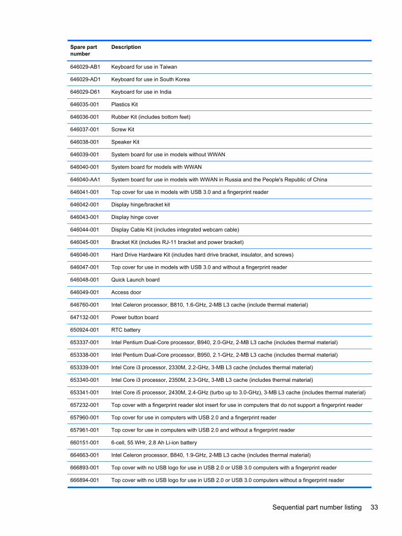
646029-AB1 Keyboard for use in Taiwan
646029-AD1 Keyboard for use in South Korea
646029-D61 Keyboard for use in India
646035-001 Plastics Kit
646036-001 Rubber Kit (includes bottom feet)
646037-001 Screw Kit
646038-001 Speaker Kit
646039-001 System board for use in models without WWAN
646040-001 System board for models with WWAN
646040-AA1 System board for use in models with WWAN in Russia and the People's Republic of China
646041-001 Top cover for use in models with USB 3.0 and a fingerprint reader
646042-001 Display hinge/bracket kit
646043-001 Display hinge cover
646044-001 Display Cable Kit (includes integrated webcam cable)
646045-001 Bracket Kit (includes RJ-11 bracket and power bracket)
646046-001 Hard Drive Hardware Kit (includes hard drive bracket, insulator, and screws)
646047-001 Top cover for use in models with USB 3.0 and without a fingerprint reader
646048-001 Quick Launch board
646049-001 Access door
646760-001 Intel Celeron processor, B810, 1.6-GHz, 2-MB L3 cache (include thermal material)
647132-001 Power button board
650924-001 RTC battery
653337-001 Intel Pentium Dual-Core processor, B940, 2.0-GHz, 2-MB L3 cache (includes thermal material)
653338-001 Intel Pentium Dual-Core processor, B950, 2.1-GHz, 2-MB L3 cache (includes thermal material)
653339-001 Intel Core i3 processor, 2330M, 2.2-GHz, 3-MB L3 cache (includes thermal material)
653340-001 Intel Core i3 processor, 2350M, 2.3-GHz, 3-MB L3 cache (includes thermal material)
653341-001 Intel Core i5 processor, 2430M, 2.4-GHz (turbo up to 3.0-GHz), 3-MB L3 cache (includes thermal material)
657232-001 Top cover with a fingerprint reader slot insert for use in computers that do not support a fingerprint reader
657960-001 Top cover for use in computers with USB 2.0 and a fingerprint reader
657961-001 Top cover for use in computers with USB 2.0 and without a fingerprint reader
660151-001 6-cell, 55 WHr, 2.8 Ah Li-ion battery
664663-001 Intel Celeron processor, B840, 1.9-GHz, 2-MB L3 cache (includes thermal material)
666893-001 Top cover with no USB logo for use in USB 2.0 or USB 3.0 computers with a fingerprint reader
666894-001 Top cover with no USB logo for use in USB 2.0 or USB 3.0 computers without a fingerprint reader
Sequential part number listing 33
4 Removal and replacement procedures
Preliminary replacement requirements
Tools required
You will need the following tools to complete the removal and replacement procedures:
● Flat-bladed screwdriver
● Phillips P0 and P1 screwdrivers
● Torx T8 screwdriver
Service considerations
The following sections include some of the considerations that you must keep in mind duringdisassembly and assembly procedures.
NOTE: As you remove each subassembly from the computer, place the subassembly (and allaccompanying screws) away from the work area to prevent damage.
Plastic parts
CAUTION: Using excessive force during disassembly and reassembly can damage plastic parts.Use care when handling the plastic parts. Apply pressure only at the points designated in themaintenance instructions.
34 Chapter 4 Removal and replacement procedures

Cables and connectors
CAUTION: When servicing the computer, be sure that cables are placed in their proper locationsduring the reassembly process. Improper cable placement can damage the computer.
Cables must be handled with extreme care to avoid damage. Apply only the tension required tounseat or seat the cables during removal and insertion. Handle cables by the connector wheneverpossible. In all cases, avoid bending, twisting, or tearing cables. Be sure that cables are routed insuch a way that they cannot be caught or snagged by parts being removed or replaced. Handle flexcables with extreme care; these cables tear easily.
Drive handling
CAUTION: Drives are fragile components that must be handled with care. To prevent damage tothe computer, damage to a drive, or loss of information, observe these precautions:
Before removing or inserting a hard drive, shut down the computer. If you are unsure whether thecomputer is off or in Hibernation, turn the computer on, and then shut it down through the operatingsystem.
Before handling a drive, be sure that you are discharged of static electricity. While handling a drive,avoid touching the connector.
Before removing a diskette drive or optical drive, be sure that a diskette or disc is not in the drive andbe sure that the optical drive tray is closed.
Handle drives on surfaces covered with at least one inch of shock-proof foam.
Avoid dropping drives from any height onto any surface.
After removing a hard drive, an optical drive, or a diskette drive, place it in a static-proof bag.
Avoid exposing a hard drive to products that have magnetic fields, such as monitors or speakers.
Avoid exposing a drive to temperature extremes or liquids.
If a drive must be mailed, place the drive in a bubble pack mailer or other suitable form of protectivepackaging and label the package “FRAGILE.”
Preliminary replacement requirements 35

Grounding guidelines
Electrostatic discharge damage
Electronic components are sensitive to electrostatic discharge (ESD). Circuitry design and structuredetermine the degree of sensitivity. Networks built into many integrated circuits provide someprotection, but in many cases, ESD contains enough power to alter device parameters or meltsilicon junctions.
A discharge of static electricity from a finger or other conductor can destroy static-sensitive devices ormicrocircuitry. Even if the spark is neither felt nor heard, damage may have occurred.
An electronic device exposed to ESD may not be affected at all and can work perfectly throughout anormal cycle. Or the device may function normally for a while, and then degrade in the internal layers,reducing its life expectancy.
CAUTION: To prevent damage to the computer when you are removing or installing internalcomponents, observe these precautions:
Keep components in their electrostatic-safe containers until you are ready to install them.
Use nonmagnetic tools.
Before touching an electronic component, discharge static electricity by using the guidelinesdescribed in this section.
Avoid touching pins, leads, and circuitry. Handle electronic components as little as possible.
If you remove a component, place it in an electrostatic-safe container.
The following table shows how humidity affects the electrostatic voltage levels generated by differentactivities.
CAUTION: A product can be degraded by as little as 700 V.
Typical electrostatic voltage levels
Relative humidity
Event 10% 40% 55%
Walking across carpet 35,000 V 15,000 V 7,500 V
Walking across vinyl floor 12,000 V 5,000 V 3,000 V
Motions of bench worker 6,000 V 800 V 400 V
Removing DIPS from plastic tube 2,000 V 700 V 400 V
Removing DIPS from vinyl tray 11,500 V 4,000 V 2,000 V
Removing DIPS from Styrofoam 14,500 V 5,000 V 3,500 V
Removing bubble pack from PCB 26,500 V 20,000 V 7,000 V
Packing PCBs in foam-lined box 21,000 V 11,000 V 5,000 V
36 Chapter 4 Removal and replacement procedures

Packaging and transporting guidelines
Follow these grounding guidelines when packaging and transporting equipment:
● To avoid hand contact, transport products in static-safe tubes, bags, or boxes.
● Protect ESD-sensitive parts and assemblies with conductive or approved containers orpackaging.
● Keep ESD-sensitive parts in their containers until the parts arrive at static-free workstations.
● Place items on a grounded surface before removing items from their containers.
● Always be properly grounded when touching a component or assembly.
● Store reusable ESD-sensitive parts from assemblies in protective packaging or nonconductivefoam.
● Use transporters and conveyors made of antistatic belts and roller bushings. Be sure thatmechanized equipment used for moving materials is wired to ground and that proper materialsare selected to avoid static charging. When grounding is not possible, use an ionizer to dissipateelectric charges.
Workstation guidelines
Follow these grounding workstation guidelines:
● Cover the workstation with approved static-shielding material.
● Use a wrist strap connected to a properly grounded work surface and use properly groundedtools and equipment.
● Use conductive field service tools, such as cutters, screwdrivers, and vacuums.
● When fixtures must directly contact dissipative surfaces, use fixtures made only of static-safematerials.
● Keep the work area free of nonconductive materials, such as ordinary plastic assembly aids andStyrofoam.
● Handle ESD-sensitive components, parts, and assemblies by the case or PCM laminate. Handlethese items only at static-free workstations.
● Avoid contact with pins, leads, or circuitry.
● Turn off power and input signals before inserting or removing connectors or test equipment.
Preliminary replacement requirements 37

Equipment guidelines
Grounding equipment must include either a wrist strap or a foot strap at a grounded workstation.
● When seated, wear a wrist strap connected to a grounded system. Wrist straps are flexiblestraps with a minimum of one megohm ±10% resistance in the ground cords. To provide properground, wear a strap snugly against the skin at all times. On grounded mats with banana-plugconnectors, use alligator clips to connect a wrist strap.
● When standing, use foot straps and a grounded floor mat. Foot straps (heel, toe, or boot straps)can be used at standing workstations and are compatible with most types of shoes or boots. Onconductive floors or dissipative floor mats, use foot straps on both feet with a minimum of onemegohm resistance between the operator and ground. To be effective, the conductive stripsmust be worn in contact with the skin.
The following grounding equipment is recommended to prevent electrostatic damage:
● Antistatic tape
● Antistatic smocks, aprons, and sleeve protectors
● Conductive bins and other assembly or soldering aids
● Nonconductive foam
● Conductive tabletop workstations with ground cords of one megohm resistance
● Static-dissipative tables or floor mats with hard ties to the ground
● Field service kits
● Static awareness labels
● Material-handling packages
● Nonconductive plastic bags, tubes, or boxes
● Metal tote boxes
● Electrostatic voltage levels and protective materials
The following table lists the shielding protection provided by antistatic bags and floor mats.
Material Use Voltage protection level
Antistatic plastic Bags 1,500 V
Carbon-loaded plastic Floor mats 7,500 V
Metallized laminate Floor mats 5,000 V
38 Chapter 4 Removal and replacement procedures

Component replacement proceduresThis chapter provides removal and replacement procedures.
There are as many as 95 screws and screw locks, in 15 different sizes, that must be removed,replaced, or loosened when servicing the computer. Make special note of each screw and screw locksize and location during removal and replacement.
Service tag
When ordering parts or requesting information, provide the computer serial number and modeldescription provided on the service tag.
● Product name (1). This is the product name affixed to the front of the computer.
● Serial number (s/n) (2). This is an alphanumeric identifier that is unique to each product.
● Part number/Product number (p/n) (3). This number provides specific information about theproduct's hardware components. The part number helps a service technician to determine whatcomponents and parts are needed.
● Warranty period (4). This number describes the duration (in years) of the warranty period for thecomputer.
● Model description (5). This is the alphanumeric identifier used to locate documents, drivers, andsupport for the computer.
Component replacement procedures 39
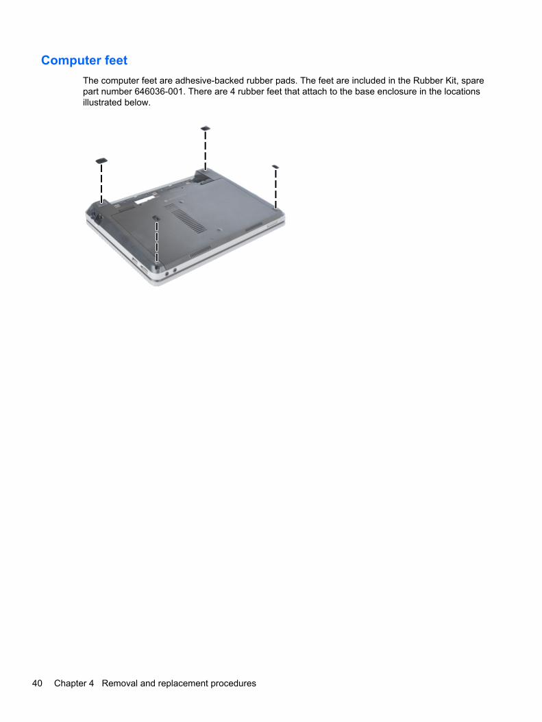
Computer feet
The computer feet are adhesive-backed rubber pads. The feet are included in the Rubber Kit, sparepart number 646036-001. There are 4 rubber feet that attach to the base enclosure in the locationsillustrated below.
40 Chapter 4 Removal and replacement procedures

Battery
Description Spare part number
6-cell, 62 WHr, 2.8 Ah Li-ion battery 633803-001
6-cell, 55 WHr, 2.8 Ah Li-ion battery 660151-001
4-cell, 41 WHr, 2.8 Ah Li-ion battery 633801-001
Before disassembling the computer, follow these steps:
1. Shut down the computer. If you are unsure whether the computer is off or in Hibernation, turnthe computer on, and then shut it down through the operating system.
2. Disconnect all external devices connected to the computer.
3. Disconnect the power from the computer by first unplugging the power cord from the AC outlet,and then unplugging the AC adapter from the computer.
Remove the battery:
1. Position the computer upside-down on a flat surface with the battery bay toward you.
2. Slide the battery release latches (1) to release the battery.
3. Rotate the battery upward (2), and then remove it from the computer (3).
Install the battery by inserting it into the battery bay until you hear a click.
Component replacement procedures 41

SIM
NOTE: This section applies only to computer models with WWAN capability.
NOTE: If there is a SIM inserted in the SIM slot, it must be removed before disassembling thecomputer. Be sure that the SIM is reinserted in the SIM slot after reassembling the computer.
Before removing the SIM, follow these steps:
1. Shut down the computer. If you are unsure whether the computer is off or in Hibernation, turnthe computer on, and then shut it down through the operating system.
2. Disconnect all external devices connected to the computer.
3. Disconnect the power from the computer by first unplugging the power cord from the AC outlet,and then unplugging the AC adapter from the computer.
4. Remove the battery (see Battery on page 41).
Remove the SIM:
1. Press in on the SIM (1). (The module is partially ejected from the SIM slot.)
2. Remove the SIM (2) from the SIM slot.
Reverse this procedure to install the SIM.
42 Chapter 4 Removal and replacement procedures

Access door
Description Spare part number
Access door 646049-001
Before disassembling the computer, follow these steps:
1. Shut down the computer. If you are unsure whether the computer is off or in Hibernation, turnthe computer on, and then shut it down through the operating system.
2. Disconnect all external devices connected to the computer.
3. Disconnect the power from the computer by first unplugging the power cord from the AC outlet,and then unplugging the AC adapter from the computer.
4. Remove the battery (see Battery on page 41).
Remove the access door:
1. Position the computer upside-down on a flat surface, with the battery bay toward you.
2. Remove the locking screw (if installed) (1) and slide the access door release latches (2) torelease the cover.
3. Slide the door toward the front of the computer, and then lift the door off the computer (3).
NOTE: The access door screw may be placed in the secure slot (4) for safekeeping while thecover is removed or if the screw is not inserted after replacing the access door.
Reverse the removal procedures to install the access door.
Component replacement procedures 43

Hard drive
NOTE: All hard drive spare part kits include a hard drive bracket and screws.
Description Spare part number
750-GB, 7200-rpm hard drive 633252-001
640-GB, 5400-rpm hard drive 603785-001
500-GB, 7200-rpm hard drive 634926-001
500-GB, 5400-rpm hard drive 634638-001
320-GB, 7200-rpm hard drive 634862-001
320-GB, 5400-rpm hard drive 645193-001
250-GB, 7200-rpm hard drive 634861-001
250-GB, 5400-rpm hard drive 645191-001
Hard Drive Hardware Kit (includes hard drive bracket, insulator, and screws) 646046-001
Before disassembling the computer, follow these steps:
1. Shut down the computer. If you are unsure whether the computer is off or in Hibernation, turnthe computer on, and then shut it down through the operating system.
2. Disconnect all external devices connected to the computer.
3. Disconnect the power from the computer by first unplugging the power cord from the AC outlet,and then unplugging the AC adapter from the computer.
4. Remove the battery (see Battery on page 41).
5. Remove the access door (see Access door on page 43).
Remove the hard drive:
1. Position the computer upside-down with the front toward you.
2. Disconnect the hard drive cable from the system board (1).
3. Remove the four Phillips PM2.0×4.0 screws (2) that secure the hard drive to the computer.
4. Lift the hard drive (3) from the hard drive bay far enough to access the hard drive cable.
44 Chapter 4 Removal and replacement procedures

5. Disconnect the hard drive cable from the hard drive (4).
6. If it is necessary to replace the hard drive bracket, remove the tape (1) that secures the Mylarcover down onto the bracket, and then lift to open the Mylar cover (2).
7. Remove the two Phillips PM3.0×3.0 hard drive bracket screws (3) from each side of the harddrive (4 total screws).
8. Rotate the hard drive upward and remove it from the bracket (4).
Reverse this procedure to reassemble and install the hard drive.
Component replacement procedures 45

Memory modules
NOTE: This procedure is valid for either memory module.
Description Spare part number
1-GB (PC3-10600, 1333-MHz, DDR3) 639736-001
2-GB (PC3-10600, 1333-MHz, DDR3) 621565-001
4-GB (PC3-10600, 1333-MHz, DDR3) 621569-001
Update BIOS before adding memory modules
Before adding new memory, make sure you update the computer to the latest BIOS.
CAUTION: Failure to update the computer to the latest BIOS prior to installing new memory mayresult in various system problems.
To update BIOS:
1. Navigate to www.hp.com.
2. Click Support & Drivers > click Drivers & Software.
3. In the Enter a product name/number box, type the computer model information, and then clickSearch.
4. Click the link for the computer model.
5. Select the operating system, and then click Next.
6. Under Step 2: Select a Download, click the BIOS link.
7. Click the link for the most recent BIOS.
8. Click the Download button, and then follow the on-screen instructions.
Before removing the memory module, follow these steps:
1. Shut down the computer. If you are unsure whether the computer is off or in Hibernation, turnthe computer on, and then shut it down through the operating system.
2. Disconnect all external devices connected to the computer.
3. Disconnect the power from the computer by first unplugging the power cord from the AC outlet,and then unplugging the AC adapter from the computer.
4. Remove the battery (see Battery on page 41).
5. Remove the access door (see Access door on page 43).
Remove the memory module:
1. Position the computer upside-down with the battery bay toward you.
2. Spread the retaining tabs (1) on each side of the memory module slot to release the memorymodule. (The edge of the module opposite the slot rises away from the computer.)
46 Chapter 4 Removal and replacement procedures

3. Remove the memory module (2) by pulling the module away from the slot at an angle.
NOTE: Memory modules are designed with a notch (3) to prevent incorrect insertion into thememory module slot.
Reverse this procedure to install a memory module.
WWAN module
CAUTION: The WWAN module and the WLAN module are not interchangeable.
Description Spare part number
HP un2430 EV-DO/HSPA Mobile Broadband Module 634400-001
HP hs2340 HSPA+ Mobile Broadband Module 632155-001
Before removing the WWAN module, follow these steps:
1. Shut down the computer. If you are unsure whether the computer is off or in Hibernation, turnthe computer on, and then shut it down through the operating system.
2. Disconnect all external devices connected to the computer.
3. Disconnect the power from the computer by first unplugging the power cord from the AC outlet,and then unplugging the AC adapter from the computer.
4. Remove the battery (see Battery on page 41).
5. Remove the SIM (see SIM on page 42).
6. Remove the access door (see Access door on page 43).
Component replacement procedures 47

Remove the WWAN module:
1. Position the computer upside-down with the battery bay toward you.
2. Disconnect the WWAN antenna cables (1) from the terminals on the WWAN module.
NOTE: The red WWAN antenna cable is connected to the WWAN module “Main” terminal. Theblue WWAN antenna cable is connected to the WWAN module “Aux” terminal.
3. Remove the two Phillips PM2.0×4.0 screws (2) that secure the WWAN module to the computer.(The edge of the module opposite the slot rises away from the computer.)
4. Remove the WWAN module (3) by pulling the module away from the slot at an angle.
NOTE: WWAN modules are designed with a notch (4) to prevent incorrect insertion.
Figure 4-1 Removing the WWAN module
NOTE: If the WWAN antennas are not connected to the terminals on the WWAN module, theprotective sleeves must be installed on the antenna connectors, as shown in the followingillustration.
Reverse this procedure to install the WWAN module.
48 Chapter 4 Removal and replacement procedures

WLAN/Bluetooth combo card
The computer uses a card that provides both WLAN and Bluetooth functionality.
CAUTION: The WLAN module and the WWAN module are not interchangeable.
Description Spare part number
Atheros AR9002WB-1NGB 802.11b/g/n 1x1 WiFi and Bluetooth 2.1+EDR Combo Adapter for usein Afghanistan, Albania, Algeria, Andorra, Angola, Antigua and Barbuda, Argentina, Armenia,Aruba, Australia, Austria, Azerbaijan, Bahamas, Bahrain, Bangladesh, Barbados, Belarus,Belgium, Belize, Benin, Bermuda, Bhutan, Bolivia, Bosnia and Herzegovina, Botswana, Brazil, theBritish Virgin Islands, Brunei, Bulgaria, Burkina Faso, Burundi, Cambodia, Cameroon, Canada,Cape Verde, the Cayman Islands, Central African Republic, Chad, Chile, People's Republic ofChina, Colombia, Comoros, Congo, Costa Rica, Croatia, Cyprus, the Czech Republic, Denmark,Djibouti, Dominica, the Dominican Republic, East Timor, Ecuador, Egypt, El Salvador, EquitorialGuinea, Eritrea, Estonia, Ethiopia, Fiji, Finland, France, French Guiana, Gabon, Gambia, Georgia,Germany, Ghana, Gibraltar, Greece, Grenada, Guadeloupe, Guam, Guatemala, Guinea, Guinea-Bissa, Guyana, Haiti, Honduras, Hong Kong, Hungary, Iceland, India, Indonesia, Ireland, Israel,Italy, Ivory Coast, Jamaica, Japan, Jordan, Kazakhstan, Kenya, Kiribati, Kuwait, Kyrgyzstan,Laos, Latvia, Lebanon, Lesotho, Liberia, Liechtenstein, Lithuania, Luxembourg, Macedonia,Madagascar, Malawi, Malaysia, Maldives, Mali, Malta, Marshall Islands, Martinique, Mauritania,Mauritius, Mexico, Micronesia, Monaco, Mongolia, Montenegro, Morocco, Mozambique, Namibia,Nauru, Nepal, the Nether Antilles, the Netherlands, New Zealand, Nicaragua, Niger, Nigeria,Norway, Oman, Pakistan, Palau, Panama, Papua New Guinea, Paraguay, Puerto Rico, Peru,Philippines, Poland, Portugal, Qatar, Republic of Moldova, Romania, Russia, Rwanda, Samoa,San Marino, Sao Tome and Principe, Saudi Arabia, Senegal, Serbia and Montenegro, Seychelles,Sierra Leone, Singapore, Slovakia, Slovenia, Solomon Islands, Somalia, South Africa, SouthKorea, Spain, Sri Lanka, St. Kitts and Nevis, St. Lucia, St. Vincent and the Grenadines, Suriname,Swaziland, Sweden, Switzerland, Syria, Taiwan, Tajikistan, Tanzania, Thailand, Togo, Tonga,Trinidad and Tobago, Tunisia, Turkey, Turkmenistan, Tuvalu, Uganda, Ukraine, the United ArabEmirates, the United Kingdom, Uruguay, the United States, the US Virgin Islands, Uzbekistan,Vanuatu, Venezuela, Vietnam, Yemen, Zaire, Zambia, and Zimbabwe
593127-001
Realtek 8188BC8 802.11a/b/g/n 2x2 WiFi and Bluetooth 3.0+HS Combo Adapter for use inAfghanistan, Albania, Algeria, Andorra, Angola, Antigua and Barbuda, Argentina, Armenia, Aruba,Australia, Austria, Azerbaijan, Bahamas, Bahrain, Baltics, Bangladesh, Barbados, Belarus,Belgium, Belize, Benin, Bermuda, Bhutan, Bolivia, Bosnia and Herzegovina, Botswana, Brazil, theBritish Virgin Islands, Brunei, Bulgaria, Burkina Faso, Burundi, Cambodia, Cameroon, Canada,Cape Verde, the Cayman Islands, Central African Republic, Chad, Chile, People's Republic ofChina, Colombia, Comoros, Congo, Costa Rica, Croatia, Cyprus, the Czech Republic, Denmark,Djibouti, Dominica, the Dominican Republic, East Timor, Ecuador, Egypt, El Salvador, EquitorialGuinea, Eritrea, Estonia, Ethiopia, Fiji, Finland, France, French Guiana, Gabon, Gambia, Georgia,Germany, Ghana, Gibraltar, Greece, Grenada, Guadeloupe, Guam, Guatemala, Guinea, Guinea-Bissa, Guyana, Haiti, Honduras, Hong Kong, Hungary, Iceland, India, Indonesia, Iraq, Ireland,Israel, Italy, Ivory Coast, Jamaica, Japan, Jordan, Kazakhstan, Kenya, Kiribati, Kuwait,Kyrgyzstan, Laos, Latvia, Lebanon, Lesotho, Liberia, Liechtenstein, Lithuania, Luxembourg,Macedonia, Madagascar, Malawi, Malaysia, Maldives, Mali, Malta, Marshall Islands, Martinique,Mauritania, Mauritius, Mexico, Micronesia, Monaco, Mongolia, Montenegro, Morocco,Mozambique, Namibia, Nauru, Nepal, the Nether Antilles, the Netherlands, New Zealand,Nicaragua, Niger, Nigeria, Norway, Oman, Pakistan, Palau, Panama, Papua New Guinea,Paraguay, Puerto Rico, Peru, Philippines, Poland, Portugal, Qatar, Republic of Moldova,Romania, Russia, Rwanda, Samoa, San Marino, Sao Tome and Principe, Saudi Arabia, Senegal,Serbia and Montenegro, Seychelles, Sierra Leone, Singapore, Slovakia, Slovenia, SolomonIslands, Somalia, South Africa, South Korea, Spain, Sri Lanka, St. Kitts and Nevis, St. Lucia, St.Vincent and the Grenadines, Suriname, Swaziland, Sweden, Switzerland, Syria, Taiwan,Tajikistan, Tanzania, Thailand, Togo, Tonga, Trinidad and Tobago, Tunisia, Turkey,Turkmenistan, Tuvalu, Uganda, Ukraine, the United Arab Emirates, the United Kingdom, Uruguay,the United States, the US Virgin Islands, Uzbekistan, Vanuatu, Venezuela, Vietnam, Yemen,Zaire, Zambia, and Zimbabwe
602993-001
Component replacement procedures 49

Description Spare part number
Ralink 5390GN 802.11b/g/n 1x1 WiFi Adapter for use in Afghanistan, Albania, Algeria, Andorra,Angola, Antigua and Barbuda, Argentina, Armenia, Aruba, Australia, Austria, Azerbaijan,Bahamas, Bahrain, Baltics, Bangladesh, Barbados, Belarus, Belgium, Belize, Benin, Bermuda,Bhutan, Bolivia, Bosnia and Herzegovina, Botswana, Brazil, the British Virgin Islands, Brunei,Bulgaria, Burkina Faso, Burundi, Cambodia, Cameroon, Canada, Cape Verde, the CaymanIslands, Central African Republic, Chad, Chile, People's Republic of China, Colombia, Comoros,Congo, Costa Rica, Croatia, Cyprus, the Czech Republic, Denmark, Djibouti, Dominica, theDominican Republic, East Timor, Ecuador, Egypt, El Salvador, Equitorial Guinea, Eritrea, Estonia,Ethiopia, Fiji, Finland, France, French Guiana, Gabon, Gambia, Georgia, Germany, Ghana,Gibraltar, Greece, Grenada, Guadeloupe, Guam, Guatemala, Guinea, Guinea-Bissa, Guyana,Haiti, Honduras, Hong Kong, Hungary, Iceland, India, Indonesia, Iraq, Ireland, Israel, Italy, IvoryCoast, Jamaica, Japan, Jordan, Kazakhstan, Kenya, Kiribati, Kuwait, Kyrgyzstan, Laos, Latvia,Lebanon, Lesotho, Liberia, Liechtenstein, Lithuania, Luxembourg, Macedonia, Madagascar,Malawi, Malaysia, Maldives, Mali, Malta, Marshall Islands, Martinique, Mauritania, Mauritius,Mexico, Micronesia, Monaco, Mongolia, Montenegro, Morocco, Mozambique, Namibia, Nauru,Nepal, the Nether Antilles, the Netherlands, New Zealand, Nicaragua, Niger, Nigeria, Norway,Oman, Pakistan, Palau, Panama, Papua New Guinea, Paraguay, Puerto Rico, Peru, Philippines,Poland, Portugal, Qatar, Republic of Moldova, Romania, Russia, Rwanda, Samoa, San Marino,Sao Tome and Principe, Saudi Arabia, Senegal, Serbia and Montenegro, Seychelles, SierraLeone, Singapore, Slovakia, Slovenia, Solomon Islands, Somalia, South Africa, South Korea,Spain, Sri Lanka, St. Kitts and Nevis, St. Lucia, St. Vincent and the Grenadines, Suriname,Swaziland, Sweden, Switzerland, Syria, Taiwan, Tajikistan, Tanzania, Thailand, Togo, Tonga,Trinidad and Tobago, Tunisia, Turkey, Turkmenistan, Tuvalu, Uganda, Ukraine, the United ArabEmirates, the United Kingdom, Uruguay, the United States, the US Virgin Islands, Uzbekistan,Vanuatu, Venezuela, Vietnam, Yemen, Zaire, Zambia, and Zimbabwe
630703-001
Ralink 8190BC8 802.11b/g/n 2x2 WiFi and Bluetooth 3.0+HS Combo Adapter for use inAfghanistan, Albania, Algeria, Andorra, Angola, Antigua and Barbuda, Argentina, Armenia, Aruba,Australia, Austria, Azerbaijan, Bahamas, Bahrain, Baltics, Bangladesh, Barbados, Belarus,Belgium, Belize, Benin, Bermuda, Bhutan, Bolivia, Bosnia and Herzegovina, Botswana, Brazil, theBritish Virgin Islands, Brunei, Bulgaria, Burkina Faso, Burundi, Cambodia, Cameroon, Canada,Cape Verde, the Cayman Islands, Central African Republic, Chad, Chile, People's Republic ofChina, Colombia, Comoros, Congo, Costa Rica, Croatia, Cyprus, the Czech Republic, Denmark,Djibouti, Dominica, the Dominican Republic, East Timor, Ecuador, Egypt, El Salvador, EquitorialGuinea, Eritrea, Estonia, Ethiopia, Fiji, Finland, France, French Guiana, Gabon, Gambia, Georgia,Germany, Ghana, Gibraltar, Greece, Grenada, Guadeloupe, Guam, Guatemala, Guinea, Guinea-Bissa, Guyana, Haiti, Honduras, Hong Kong, Hungary, Iceland, India, Indonesia, Iraq, Ireland,Israel, Italy, Ivory Coast, Jamaica, Japan, Jordan, Kazakhstan, Kenya, Kiribati, Kuwait,Kyrgyzstan, Laos, Latvia, Lebanon, Lesotho, Liberia, Liechtenstein, Lithuania, Luxembourg,Macedonia, Madagascar, Malawi, Malaysia, Maldives, Mali, Malta, Marshall Islands, Martinique,Mauritania, Mauritius, Mexico, Micronesia, Monaco, Mongolia, Montenegro, Morocco,Mozambique, Namibia, Nauru, Nepal, the Nether Antilles, the Netherlands, New Zealand,Nicaragua, Niger, Nigeria, Norway, Oman, Pakistan, Palau, Panama, Papua New Guinea,Paraguay, Puerto Rico, Peru, Philippines, Poland, Portugal, Qatar, Republic of Moldova,Romania, Russia, Rwanda, Samoa, San Marino, Sao Tome and Principe, Saudi Arabia, Senegal,Serbia and Montenegro, Seychelles, Sierra Leone, Singapore, Slovakia, Slovenia, SolomonIslands, Somalia, South Africa, South Korea, Spain, Sri Lanka, St. Kitts and Nevis, St. Lucia, St.Vincent and the Grenadines, Suriname, Swaziland, Sweden, Switzerland, Syria, Taiwan,Tajikistan, Tanzania, Thailand, Togo, Tonga, Trinidad and Tobago, Tunisia, Turkey,Turkmenistan, Tuvalu, Uganda, Ukraine, the United Arab Emirates, the United Kingdom, Uruguay,the United States, the US Virgin Islands, Uzbekistan, Vanuatu, Venezuela, Vietnam, Yemen,Zaire, Zambia, and Zimbabwe
630813-001
50 Chapter 4 Removal and replacement procedures

Description Spare part number
Realtek 8188GN 802.11b/g/n 1x1 WiFi Adapter for use in Afghanistan, Albania, Algeria, Andorra,Angola, Antigua and Barbuda, Argentina, Armenia, Aruba, Australia, Austria, Azerbaijan,Bahamas, Bahrain, Baltics, Bangladesh, Barbados, Belarus, Belgium, Belize, Benin, Bermuda,Bhutan, Bolivia, Bosnia and Herzegovina, Botswana, Brazil, the British Virgin Islands, Brunei,Bulgaria, Burkina Faso, Burundi, Cambodia, Cameroon, Canada, Cape Verde, the CaymanIslands, Central African Republic, Chad, Chile, People's Republic of China, Colombia, Comoros,Congo, Costa Rica, Croatia, Cyprus, the Czech Republic, Denmark, Djibouti, Dominica, theDominican Republic, East Timor, Ecuador, Egypt, El Salvador, Equitorial Guinea, Eritrea, Estonia,Ethiopia, Fiji, Finland, France, French Guiana, Gabon, Gambia, Georgia, Germany, Ghana,Gibraltar, Greece, Grenada, Guadeloupe, Guam, Guatemala, Guinea, Guinea-Bissa, Guyana,Haiti, Honduras, Hong Kong, Hungary, Iceland, India, Indonesia, Iraq, Ireland, Israel, Italy, IvoryCoast, Jamaica, Japan, Jordan, Kazakhstan, Kenya, Kiribati, Kuwait, Kyrgyzstan, Laos, Latvia,Lebanon, Lesotho, Liberia, Liechtenstein, Lithuania, Luxembourg, Macedonia, Madagascar,Malawi, Malaysia, Maldives, Mali, Malta, Marshall Islands, Martinique, Mauritania, Mauritius,Mexico, Micronesia, Monaco, Mongolia, Montenegro, Morocco, Mozambique, Namibia, Nauru,Nepal, the Nether Antilles, the Netherlands, New Zealand, Nicaragua, Niger, Nigeria, Norway,Oman, Pakistan, Palau, Panama, Papua New Guinea, Paraguay, Puerto Rico, Peru, Philippines,Poland, Portugal, Qatar, Republic of Moldova, Romania, Russia, Rwanda, Samoa, San Marino,Sao Tome and Principe, Saudi Arabia, Senegal, Serbia and Montenegro, Seychelles, SierraLeone, Singapore, Slovakia, Slovenia, Solomon Islands, Somalia, South Africa, South Korea,Spain, Sri Lanka, St. Kitts and Nevis, St. Lucia, St. Vincent and the Grenadines, Suriname,Swaziland, Sweden, Switzerland, Syria, Taiwan, Tajikistan, Tanzania, Thailand, Togo, Tonga,Trinidad and Tobago, Tunisia, Turkey, Turkmenistan, Tuvalu, Uganda, Ukraine, the United ArabEmirates, the United Kingdom, Uruguay, the United States, the US Virgin Islands, Uzbekistan,Vanuatu, Venezuela, Vietnam, Yemen, Zaire, Zambia, and Zimbabwe
640926-001
Intel Centrino Advanced-N 6230 for use in Afghanistan, Albania, Algeria, Andorra, Angola,Antigua and Barbuda, Argentina, Armenia, Aruba, Australia, Austria, Azerbaijan, Bahamas,Bahrain, Baltics, Bangladesh, Barbados, Belarus, Belgium, Belize, Benin, Bermuda, Bhutan,Bolivia, Bosnia and Herzegovina, Botswana, Brazil, the British Virgin Islands, Brunei, Bulgaria,Burkina Faso, Burundi, Cambodia, Cameroon, Canada, Cape Verde, the Cayman Islands, CentralAfrican Republic, Chad, Chile, People's Republic of China, Colombia, Comoros, Congo, CostaRica, Croatia, Cyprus, the Czech Republic, Denmark, Djibouti, Dominica, the Dominican Republic,East Timor, Ecuador, Egypt, El Salvador, Equitorial Guinea, Eritrea, Estonia, Ethiopia, Fiji,Finland, France, French Guiana, Gabon, Gambia, Georgia, Germany, Ghana, Gibraltar, Greece,Grenada, Guadeloupe, Guam, Guatemala, Guinea, Guinea-Bissa, Guyana, Haiti, Honduras,Hong Kong, Hungary, Iceland, India, Indonesia, Iraq, Ireland, Israel, Italy, Ivory Coast, Jamaica,Japan, Jordan, Kazakhstan, Kenya, Kiribati, Kuwait, Kyrgyzstan, Laos, Latvia, Lebanon, Lesotho,Liberia, Liechtenstein, Lithuania, Luxembourg, Macedonia, Madagascar, Malawi, Malaysia,Maldives, Mali, Malta, Marshall Islands, Martinique, Mauritania, Mauritius, Mexico, Micronesia,Monaco, Mongolia, Montenegro, Morocco, Mozambique, Namibia, Nauru, Nepal, the NetherAntilles, the Netherlands, New Zealand, Nicaragua, Niger, Nigeria, Norway, Oman, Pakistan,Palau, Panama, Papua New Guinea, Paraguay, Puerto Rico, Peru, Philippines, Poland, Portugal,Qatar, Republic of Moldova, Romania, Russia, Rwanda, Samoa, San Marino, Sao Tome andPrincipe, Saudi Arabia, Senegal, Serbia and Montenegro, Seychelles, Sierra Leone, Singapore,Slovakia, Slovenia, Solomon Islands, Somalia, South Africa, South Korea, Spain, Sri Lanka, St.Kitts and Nevis, St. Lucia, St. Vincent and the Grenadines, Suriname, Swaziland, Sweden,Switzerland, Syria, Taiwan, Tajikistan, Tanzania, Thailand, Togo, Tonga, Trinidad and Tobago,Tunisia, Turkey, Turkmenistan, Tuvalu, Uganda, Ukraine, the United Arab Emirates, the UnitedKingdom, Uruguay, the United States, the US Virgin Islands, Uzbekistan, Vanuatu, Venezuela,Vietnam, Yemen, Zaire, Zambia, and Zimbabwe
636672-001
Before removing the WLAN module, follow these steps:
1. Shut down the computer. If you are unsure whether the computer is off or in Hibernation, turnthe computer on, and then shut it down through the operating system.
2. Disconnect all external devices connected to the computer.
Component replacement procedures 51

3. Disconnect the power from the computer by first unplugging the power cord from the AC outlet,and then unplugging the AC adapter from the computer.
4. Remove the battery (see Battery on page 41).
5. Remove the access door (see Access door on page 43).
Remove the WLAN module:
1. Position the computer upside-down with the battery bay toward you.
2. Disconnect the WLAN antenna cables (1) from the terminals on the WLAN module.
NOTE: The WLAN antenna cable labeled “1” connects to the WLAN module “Main” terminallabeled “1”. The WLAN antenna cable labeled “2” connects to the WLAN module “Aux” terminallabeled “2”. If the computer is equipped with an 802.11a/b/g/n WLAN module, the yellow WLANantenna cable connects to the middle terminal on the WLAN module.
3. Remove the two Phillips PM2.0×4.0 screws (2) that secure the WLAN module to the computer.(The edge of the module opposite the slot rises away from the computer.)
52 Chapter 4 Removal and replacement procedures

4. Remove the WLAN module (3) by pulling the module away from the slot at an angle.
NOTE: WLAN modules are designed with a notch (4) to prevent incorrect insertion.
NOTE: If the WLAN antennas are not connected to the terminals on the WLAN module, theprotective sleeves must be installed on the antenna connectors, as shown in the followingillustration.
Reverse this procedure to install the WLAN module.
Component replacement procedures 53
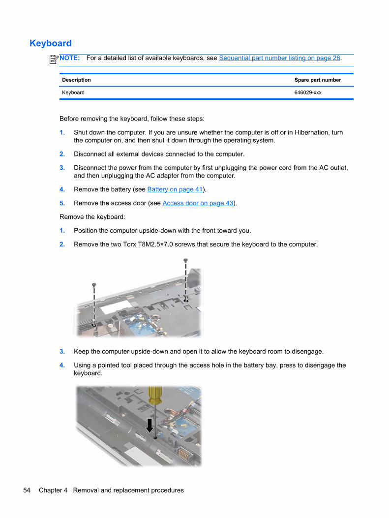
Keyboard
NOTE: For a detailed list of available keyboards, see Sequential part number listing on page 28.
Description Spare part number
Keyboard 646029-xxx
Before removing the keyboard, follow these steps:
1. Shut down the computer. If you are unsure whether the computer is off or in Hibernation, turnthe computer on, and then shut it down through the operating system.
2. Disconnect all external devices connected to the computer.
3. Disconnect the power from the computer by first unplugging the power cord from the AC outlet,and then unplugging the AC adapter from the computer.
4. Remove the battery (see Battery on page 41).
5. Remove the access door (see Access door on page 43).
Remove the keyboard:
1. Position the computer upside-down with the front toward you.
2. Remove the two Torx T8M2.5×7.0 screws that secure the keyboard to the computer.
3. Keep the computer upside-down and open it to allow the keyboard room to disengage.
4. Using a pointed tool placed through the access hole in the battery bay, press to disengage thekeyboard.
54 Chapter 4 Removal and replacement procedures

5. Position the computer upright and open it as far as possible.
6. Using a slim screwdriver, release the four top keyboard tabs at the indicated locations and lift thetop of the keyboard up and place it on the palm rest.
7. Lift the keyboard connector latch and disconnect the keyboard cable from the system board.
8. Remove the keyboard from the computer.
Reverse this procedure to install the keyboard.
Top cover
Description Spare part number
Top cover for use in models with USB 3.0 and a fingerprint reader 646041-001
Top cover for use in models with USB 3.0 and without a fingerprint reader 646047-001
Top cover with a fingerprint reader slot insert for use in computers that do not support a fingerprintreader
657232-001
Top cover for use in computers with USB 2.0 and a fingerprint reader 657960-001
Top cover for use in computers with USB 2.0 and without a fingerprint reader 657961-001
Top cover with no USB logo for use in USB 2.0 or USB 3.0 computers with a fingerprint reader 666893-001
Top cover with no USB logo for use in USB 2.0 or USB 3.0 computers without a fingerprint reader 666894-001
Component replacement procedures 55

Before removing the top cover, follow these steps:
1. Shut down the computer. If you are unsure whether the computer is off or in Hibernation, turnthe computer on, and then shut it down through the operating system.
2. Disconnect all external devices connected to the computer.
3. Disconnect the power from the computer by first unplugging the power cord from the AC outlet,and then unplugging the AC adapter from the computer.
4. Remove the battery (see Battery on page 41).
5. Remove the following components:
a. Access door (see Access door on page 43).
b. WLAN module (see WLAN/Bluetooth combo card on page 49)
c. WWAN module (see WWAN module on page 47)
d. Keyboard (see Keyboard on page 54)
Remove the top cover:
1. Position the computer upside-down with the front toward you.
2. Remove the 4 rubber screw covers (1) and 6 Torx T8M2.5×8.0 screws (2) that secure the topcover to the computer:
3. Turn the computer upright and open it as far as possible.
4. Remove the 5 Torx T8M2.5×6.0 screws (1) and the Phillips PM2.0×4.0 screw (2) that securesthe top cover to the computer.
56 Chapter 4 Removal and replacement procedures

5. Remove the following cables from the system board:
(3) Power button
(4) QuickLaunch board
(5) Card reader
(6) Touchpad
6. Position the upside-down with the battery bay toward you.
7. Insert a screwdriver through the holes in the battery bay and press to disengage the top coverfrom the computer.
8. Position the computer upright with the front toward you.
Component replacement procedures 57
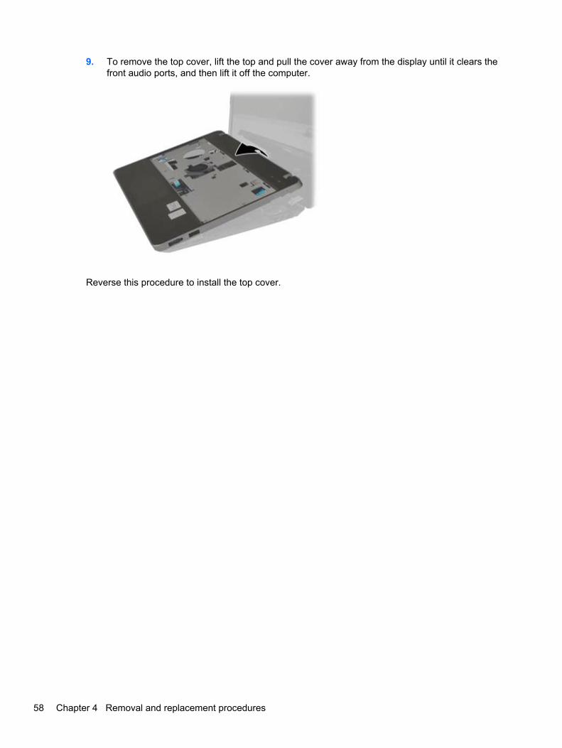
9. To remove the top cover, lift the top and pull the cover away from the display until it clears thefront audio ports, and then lift it off the computer.
Reverse this procedure to install the top cover.
58 Chapter 4 Removal and replacement procedures

Quick Launch board
Description Spare part number
Quick Launch board 646048-001
Before removing the Quick Launch board, follow these steps:
1. Shut down the computer. If you are unsure whether the computer is off or in Hibernation, turnthe computer on, and then shut it down through the operating system.
2. Disconnect all external devices connected to the computer.
3. Disconnect the power from the computer by first unplugging the power cord from the AC outlet,and then unplugging the AC adapter from the computer.
4. Remove the battery (see Battery on page 41).
5. Remove the following components:
a. Access door (see Access door on page 43).
b. WLAN module (see WLAN/Bluetooth combo card on page 49)
c. WWAN module (see WWAN module on page 47)
d. Keyboard (see Keyboard on page 54)
e. Top cover (see Top cover on page 55)
Remove the Quick Launch board:
1. Position the top cover upside-down with the front toward you.
2. Remove the two Phillips PM2.0×4.0 screws (1) that secure the board to the top cover.
3. Lift the board straight up and off the top cover (2).
Reverse this procedure to install the Quick Launch board.
Component replacement procedures 59
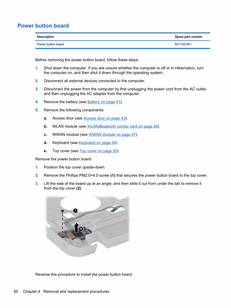
Power button board
Description Spare part number
Power button board 647132-001
Before removing the power button board, follow these steps:
1. Shut down the computer. If you are unsure whether the computer is off or in Hibernation, turnthe computer on, and then shut it down through the operating system.
2. Disconnect all external devices connected to the computer.
3. Disconnect the power from the computer by first unplugging the power cord from the AC outlet,and then unplugging the AC adapter from the computer.
4. Remove the battery (see Battery on page 41).
5. Remove the following components:
a. Access door (see Access door on page 43).
b. WLAN module (see WLAN/Bluetooth combo card on page 49)
c. WWAN module (see WWAN module on page 47)
d. Keyboard (see Keyboard on page 54)
e. Top cover (see Top cover on page 55)
Remove the power button board:
1. Position the top cover upside-down.
2. Remove the Phillips PM2.0×4.0 screw (1) that secures the power button board to the top cover.
3. Lift the side of the board up at an angle, and then slide it out from under the tab to remove itfrom the top cover (2).
Reverse this procedure to install the power button board.
60 Chapter 4 Removal and replacement procedures

Modem module
NOTE: The modem module spare part kit does not include a modem module cable. The modemmodule cable is included in the Cable Kit, spare part number 646016-001. See Cable Kit on page 26for more Cable Kit spare part number information.
Description Spare part number
Modem module 628824-001
Before removing the modem module, follow these steps:
1. Shut down the computer. If you are unsure whether the computer is off or in Hibernation, turnthe computer on, and then shut it down through the operating system.
2. Disconnect all external devices connected to the computer.
3. Disconnect the power from the computer by first unplugging the power cord from the AC outlet,and then unplugging the AC adapter from the computer.
4. Remove the battery (see Battery on page 41).
5. Remove the following components:
a. Access door (see Access door on page 43).
b. WLAN module (see WLAN/Bluetooth combo card on page 49)
c. WWAN module (see WWAN module on page 47)
d. Keyboard (see Keyboard on page 54)
e. Top cover (see Top cover on page 55)
Remove the modem module:
1. Position the computer upright and open it.
2. Remove the two Phillips PM2.0×4.0 screws (1) that secure the modem module to the systemboard.
3. Lift the modem straight up (2) to disconnect it from the system board.
Component replacement procedures 61

4. Disconnect the modem module cable (3) from the modem module.
Reverse this procedure to install the modem module.
Speaker assembly
Description Spare part number
Speaker Kit 646038-001
Before removing the speaker assembly, follow these steps:
1. Shut down the computer. If you are unsure whether the computer is off or in Hibernation, turnthe computer on, and then shut it down through the operating system.
2. Disconnect all external devices connected to the computer.
3. Disconnect the power from the computer by first unplugging the power cord from the AC outlet,and then unplugging the AC adapter from the computer.
4. Remove the battery (see Battery on page 41).
5. Remove the following components:
a. Access door (see Access door on page 43).
b. WLAN module (see WLAN/Bluetooth combo card on page 49)
c. WWAN module (see WWAN module on page 47)
d. Keyboard (see Keyboard on page 54)
e. Top cover (see Top cover on page 55)
f. Modem module (see Modem module on page 61)
62 Chapter 4 Removal and replacement procedures

Remove the speaker assembly:
1. Position the computer upright with the front toward you.
2. Disconnect the cable from the system board (1).
3. Remove the tape the secures the speaker cable to the system board (2).
4. Lift the speaker from the computer (3).
Reverse this procedure to install the speaker assembly.
System board
NOTE: All system board spare part kits include replacement thermal material.
Description Spare part number
System board for use in models without WWAN 646039-001
System board for use in models with WWAN 646040-001
System board for use in models with WWAN in Russia and the People's Republic of China 646040-AA1
Before removing the system board, follow these steps:
1. Shut down the computer. If you are unsure whether the computer is off or in Hibernation, turnthe computer on, and then shut it down through the operating system.
2. Disconnect all external devices connected to the computer.
3. Disconnect the power from the computer by first unplugging the power cord from the AC outlet,and then unplugging the AC adapter from the computer.
Component replacement procedures 63

4. Remove the battery (see Battery on page 41).
5. Remove the following components:
a. Access door (see Access door on page 43).
b. Hard drive (see Hard drive on page 44)
c. Keyboard (see Keyboard on page 54)
d. Top cover (see Top cover on page 55)
e. Speaker assembly (see Speaker assembly on page 62)
When replacing the system board, be sure to remove the following components from the defectivesystem board and install on the replacement system board:
● SIM (see SIM on page 42)
● Memory module (see Memory modules on page 46)
● WLAN module (see WLAN/Bluetooth combo card on page 49)
● WWAN module (see WWAN module on page 47)
● Modem module (see Modem module on page 61)
● Processor (see Processor on page 71)
Remove the system board:
1. Position the computer upright and open it.
2. Disconnect the display cable from the system board (1) and lift it aside.
3. Remove the Phillips PM2.5×5.0 screw (2) that secures the system board to the base enclosure.
4. Remove the Phillips PM2.5×7.0 screw (3) that secures the system board to the base enclosure.
5. Lift to remove the power connector bracket on the right side of the system board (4).
The power connector bracket is available in the Bracket Kit, spare part number 646045-001.
64 Chapter 4 Removal and replacement procedures
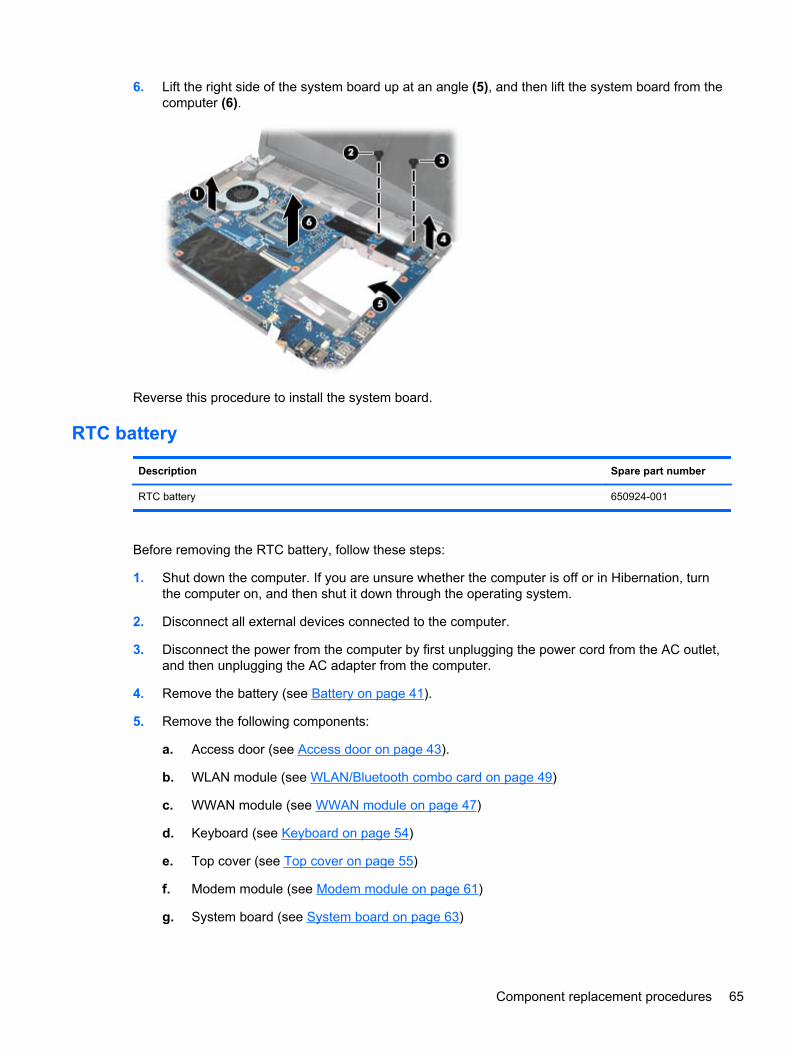
6. Lift the right side of the system board up at an angle (5), and then lift the system board from thecomputer (6).
Reverse this procedure to install the system board.
RTC battery
Description Spare part number
RTC battery 650924-001
Before removing the RTC battery, follow these steps:
1. Shut down the computer. If you are unsure whether the computer is off or in Hibernation, turnthe computer on, and then shut it down through the operating system.
2. Disconnect all external devices connected to the computer.
3. Disconnect the power from the computer by first unplugging the power cord from the AC outlet,and then unplugging the AC adapter from the computer.
4. Remove the battery (see Battery on page 41).
5. Remove the following components:
a. Access door (see Access door on page 43).
b. WLAN module (see WLAN/Bluetooth combo card on page 49)
c. WWAN module (see WWAN module on page 47)
d. Keyboard (see Keyboard on page 54)
e. Top cover (see Top cover on page 55)
f. Modem module (see Modem module on page 61)
g. System board (see System board on page 63)
Component replacement procedures 65

Remove the RTC battery:
1. Position the system board upside-down.
2. Use a screwdriver to loosen the battery from the slot (1).
3. Lift the battery from the system board (2).
Reverse this procedure to install the RTC battery.
66 Chapter 4 Removal and replacement procedures

Fan
Description Spare part number
Fan 646027-001
Before removing the fan, follow these steps:
1. Shut down the computer. If you are unsure whether the computer is off or in Hibernation, turnthe computer on, and then shut it down through the operating system.
2. Disconnect all external devices connected to the computer.
3. Disconnect the power from the computer by first unplugging the power cord from the AC outlet,and then unplugging the AC adapter from the computer.
4. Remove the battery (see Battery on page 41).
5. Remove the following components:
a. Access door (see Access door on page 43).
b. WLAN module (see WLAN/Bluetooth combo card on page 49)
c. WWAN module (see WWAN module on page 47)
d. Keyboard (see Keyboard on page 54)
e. Top cover (see Top cover on page 55)
f. Modem module (see Modem module on page 61)
g. System board (see System board on page 63)
Remove the fan:
1. Position the system board upside-down.
2. Remove the Phillips PM2.5×4.0 screw (1) that secures the fan to the system board.
3. Disconnect the fan cable (2) from the system board.
Component replacement procedures 67
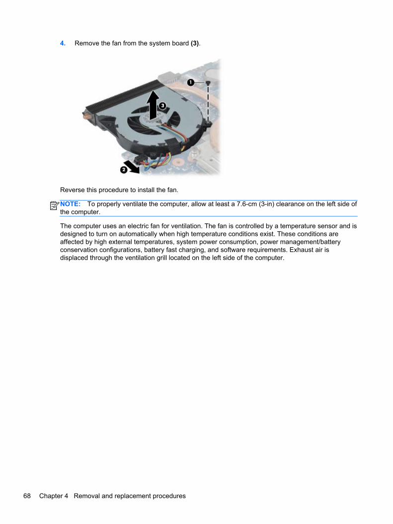
4. Remove the fan from the system board (3).
Reverse this procedure to install the fan.
NOTE: To properly ventilate the computer, allow at least a 7.6-cm (3-in) clearance on the left side ofthe computer.
The computer uses an electric fan for ventilation. The fan is controlled by a temperature sensor and isdesigned to turn on automatically when high temperature conditions exist. These conditions areaffected by high external temperatures, system power consumption, power management/batteryconservation configurations, battery fast charging, and software requirements. Exhaust air isdisplaced through the ventilation grill located on the left side of the computer.
68 Chapter 4 Removal and replacement procedures

Heat sink
All heat sink spare part kits include replacement thermal material.
Description Spare part number
Heat sink 646028-001
Before removing the heat sink, follow these steps:
1. Shut down the computer. If you are unsure whether the computer is off or in Hibernation, turnthe computer on, and then shut it down through the operating system.
2. Disconnect all external devices connected to the computer.
3. Disconnect the power from the computer by first unplugging the power cord from the AC outlet,and then unplugging the AC adapter from the computer.
4. Remove the battery (see Battery on page 41).
5. Remove the following components:
a. Access door (see Access door on page 43).
b. WLAN module (see WLAN/Bluetooth combo card on page 49)
c. WWAN module (see WWAN module on page 47)
d. Keyboard (see Keyboard on page 54)
e. Top cover (see Top cover on page 55)
f. Modem module (see Modem module on page 61)
g. System board (see System board on page 63)
h. Fan (see Fan on page 67)
Remove the heat sink:
1. Position the system board upside-down.
2. To remove the heat sink, in the order indicated, loosen the four captive Phillips screws (1) — (4)that secure the heat sink to the system board.
Component replacement procedures 69

3. Remove the heat sink from the system board (5).
NOTE: Thoroughly clean thermal material from the surfaces of the system board component (1) andthe heat sink (2) each time you remove the heat sink. All heat sink and processor spare part kitsinclude thermal material.
Reverse this procedure to install the heat sink.
70 Chapter 4 Removal and replacement procedures
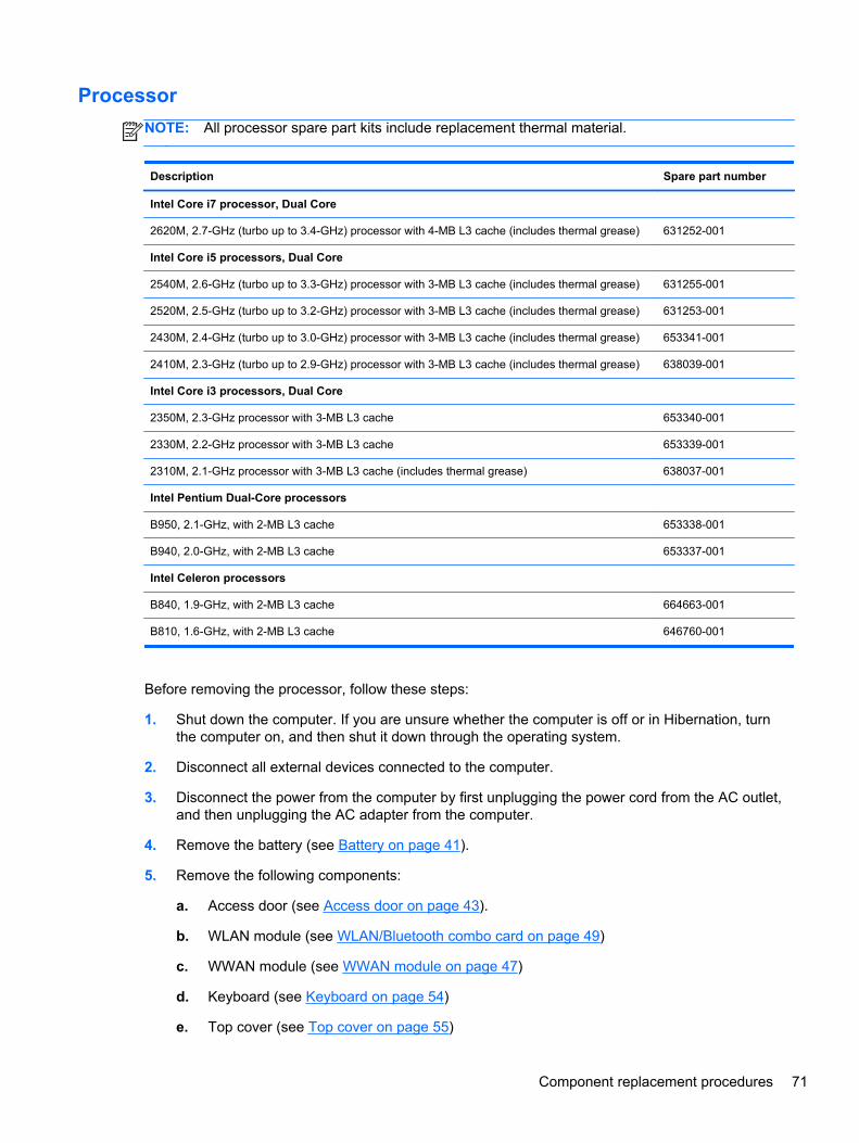
Processor
NOTE: All processor spare part kits include replacement thermal material.
Description Spare part number
Intel Core i7 processor, Dual Core
2620M, 2.7-GHz (turbo up to 3.4-GHz) processor with 4-MB L3 cache (includes thermal grease) 631252-001
Intel Core i5 processors, Dual Core
2540M, 2.6-GHz (turbo up to 3.3-GHz) processor with 3-MB L3 cache (includes thermal grease) 631255-001
2520M, 2.5-GHz (turbo up to 3.2-GHz) processor with 3-MB L3 cache (includes thermal grease) 631253-001
2430M, 2.4-GHz (turbo up to 3.0-GHz) processor with 3-MB L3 cache (includes thermal grease) 653341-001
2410M, 2.3-GHz (turbo up to 2.9-GHz) processor with 3-MB L3 cache (includes thermal grease) 638039-001
Intel Core i3 processors, Dual Core
2350M, 2.3-GHz processor with 3-MB L3 cache 653340-001
2330M, 2.2-GHz processor with 3-MB L3 cache 653339-001
2310M, 2.1-GHz processor with 3-MB L3 cache (includes thermal grease) 638037-001
Intel Pentium Dual-Core processors
B950, 2.1-GHz, with 2-MB L3 cache 653338-001
B940, 2.0-GHz, with 2-MB L3 cache 653337-001
Intel Celeron processors
B840, 1.9-GHz, with 2-MB L3 cache 664663-001
B810, 1.6-GHz, with 2-MB L3 cache 646760-001
Before removing the processor, follow these steps:
1. Shut down the computer. If you are unsure whether the computer is off or in Hibernation, turnthe computer on, and then shut it down through the operating system.
2. Disconnect all external devices connected to the computer.
3. Disconnect the power from the computer by first unplugging the power cord from the AC outlet,and then unplugging the AC adapter from the computer.
4. Remove the battery (see Battery on page 41).
5. Remove the following components:
a. Access door (see Access door on page 43).
b. WLAN module (see WLAN/Bluetooth combo card on page 49)
c. WWAN module (see WWAN module on page 47)
d. Keyboard (see Keyboard on page 54)
e. Top cover (see Top cover on page 55)
Component replacement procedures 71
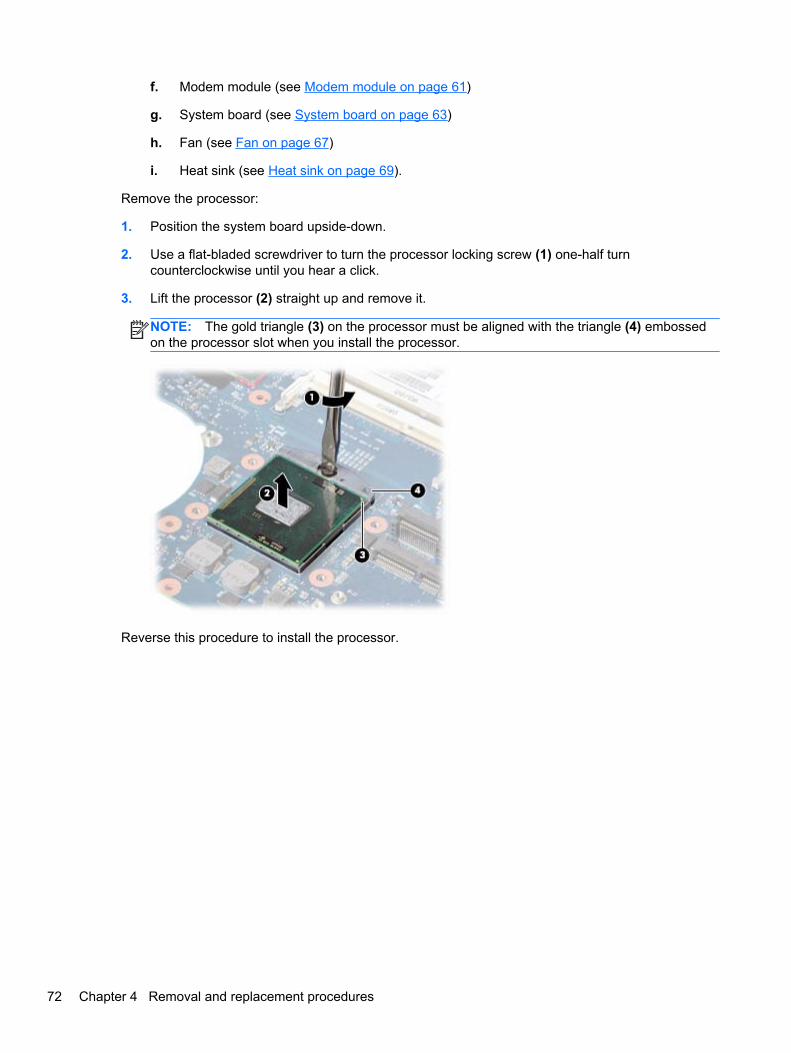
f. Modem module (see Modem module on page 61)
g. System board (see System board on page 63)
h. Fan (see Fan on page 67)
i. Heat sink (see Heat sink on page 69).
Remove the processor:
1. Position the system board upside-down.
2. Use a flat-bladed screwdriver to turn the processor locking screw (1) one-half turncounterclockwise until you hear a click.
3. Lift the processor (2) straight up and remove it.
NOTE: The gold triangle (3) on the processor must be aligned with the triangle (4) embossedon the processor slot when you install the processor.
Reverse this procedure to install the processor.
72 Chapter 4 Removal and replacement procedures

RJ-11 jack cable
NOTE: The RJ-11 jack cable is included in the Cable Kit, spare part number 646016-001.
The RJ-11 bracket is available in the Bracket Kit, spare part number 646045-001.
Before removing the RJ-11 jack cable, follow these steps:
1. Shut down the computer. If you are unsure whether the computer is off or in Hibernation, turnthe computer on, and then shut it down through the operating system.
2. Disconnect all external devices connected to the computer.
3. Disconnect the power from the computer by first unplugging the power cord from the AC outlet,and then unplugging the AC adapter from the computer.
4. Remove the battery (see Battery on page 41).
5. Remove the following components:
a. Access door (see Access door on page 43).
b. WLAN module (see WLAN/Bluetooth combo card on page 49)
c. WWAN module (see WWAN module on page 47)
d. Keyboard (see Keyboard on page 54)
e. Top cover (see Top cover on page 55)
f. Modem module (see Modem module on page 61)
g. System board (see System board on page 63)
Remove the RJ-11 jack cable:
1. Position the base enclosure upright with the front toward you.
2. Remove the Phillips PM2.0×4.0 screw (1) that secures the RJ-11 jack to the enclosure.
3. Remove the RJ-11 jack cable (2) from the tape, clips, and routing channel (3) built into the baseenclosure.
Component replacement procedures 73
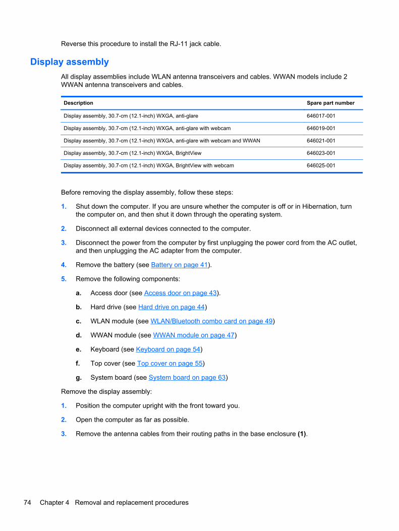
Reverse this procedure to install the RJ-11 jack cable.
Display assembly
All display assemblies include WLAN antenna transceivers and cables. WWAN models include 2WWAN antenna transceivers and cables.
Description Spare part number
Display assembly, 30.7-cm (12.1-inch) WXGA, anti-glare 646017-001
Display assembly, 30.7-cm (12.1-inch) WXGA, anti-glare with webcam 646019-001
Display assembly, 30.7-cm (12.1-inch) WXGA, anti-glare with webcam and WWAN 646021-001
Display assembly, 30.7-cm (12.1-inch) WXGA, BrightView 646023-001
Display assembly, 30.7-cm (12.1-inch) WXGA, BrightView with webcam 646025-001
Before removing the display assembly, follow these steps:
1. Shut down the computer. If you are unsure whether the computer is off or in Hibernation, turnthe computer on, and then shut it down through the operating system.
2. Disconnect all external devices connected to the computer.
3. Disconnect the power from the computer by first unplugging the power cord from the AC outlet,and then unplugging the AC adapter from the computer.
4. Remove the battery (see Battery on page 41).
5. Remove the following components:
a. Access door (see Access door on page 43).
b. Hard drive (see Hard drive on page 44)
c. WLAN module (see WLAN/Bluetooth combo card on page 49)
d. WWAN module (see WWAN module on page 47)
e. Keyboard (see Keyboard on page 54)
f. Top cover (see Top cover on page 55)
g. System board (see System board on page 63)
Remove the display assembly:
1. Position the computer upright with the front toward you.
2. Open the computer as far as possible.
3. Remove the antenna cables from their routing paths in the base enclosure (1).
74 Chapter 4 Removal and replacement procedures

4. Remove the five Phillips PM2.5×8.0 screws (2) from the hinges, the Phillips PM2.5×8.0 screw(3) from the security bracket, and then lift the display from the computer (4).
When installing the display assembly, be sure that the wireless antenna cables are routed andarranged properly.
Failure to properly route the antennas can result in degradation of the computer's WLAN andWWAN performance.
5. To replace the display bezel, remove the two rubber screw covers and the two PhillipsPM2.5×5.0 screws (1) in the bottom corners of the display bezel.
6. Flex the bottom (2) of the bezel, the inside edges of the left and right sides (3), and then the top(4) of the bezel until it disengages from the display enclosure.
The bezel is available using the following spare part numbers:
646015-001: models without a webcam
646014-001: models with a webcam
7. The hinge covers (5) slide off the hinges when you remove the bezel.
The hinge covers are available using spare part number 646043-001
8. Remove the display bezel.
Component replacement procedures 75

9. If it is necessary to replace the webcam module (shown in the following image) or microphonemodule from the display enclosure, disconnect the cable from the module (1), and then gentlypull the module away from the double-sided tape on the display enclosure (2).
The webcam module is available using spare part number 642795-001.
The microphone module is removed using the same procedure and is available using spare partnumber 642797-001.
10. If it is necessary to remove the display panel, remove the two Phillips PM2.5×5.0 screws (1) atthe bottom and two Phillips PM2.5×5.0 broadhead screws (2) at the top that secure the panel tothe display enclosure.
11. Lift the panel out of the display enclosure (3).
76 Chapter 4 Removal and replacement procedures

12. Disconnect the display panel cable from the back of the display panel by pressing the latches onthe side of the connector (1), and then disconnecting the cable from the panel (2).
The display cable is available using spare part number 646044-001, and includes the integratedwebcam cable.
13. If it is necessary to replace the display hinges, remove the two Phillips PM2.5×3.0 screws thatsecure each display hinge to the display panel, and then remove the hinges from the panel.
Display hinges are available using spare part number 646042-001.
Component replacement procedures 77

14. If you need to remove the WLAN or WWAN antennas, lift the WLAN antenna cables (1) orWWAN antenna cables (2) from the clips and routing paths built into the display enclosure.
The WLAN antennas are available using spare part number 646010-001, and the WWANantennas are available using spare part number 646011-001.
CAUTION: When installing the display assembly, be sure that the wireless antenna cables arerouted and arranged properly.
Failure to properly route the antennas can result in degradation of the computer's wirelessperformance.
Reverse this procedure to reassemble and install the display assembly.
78 Chapter 4 Removal and replacement procedures

5 Computer Setup (BIOS) and SystemDiagnostics
Using Computer SetupComputer Setup, or Basic Input/Output System (BIOS), controls communication between all the inputand output devices on the system (such as disk drives, display, keyboard, mouse, and printer).Computer Setup includes settings for the types of devices installed, the startup sequence of thecomputer, and the amount of system and extended memory.
NOTE: Use extreme care when making changes in Computer Setup. Errors can prevent thecomputer from operating properly.
Starting Computer Setup
NOTE: An external keyboard or mouse connected to a USB port can be used with Computer Setuponly if USB legacy support is enabled.
To start Computer Setup, follow these steps:
1. Turn on or restart the computer, and then press esc while the “Press the ESC key for StartupMenu” message is displayed at the bottom of the screen.
2. Press f10 to enter Computer Setup.
Navigating and selecting in Computer Setup
To navigate and select in Computer Setup, follow these steps:
1. Turn on or restart the computer, and then press esc while the “Press the ESC key for StartupMenu” message is displayed at the bottom of the screen.
● To select a menu or a menu item, use the tab key and the keyboard arrow keys and thenpress enter, or use a pointing device to click the item.
● To scroll up and down, click the up arrow or the down arrow in the upper-right corner of thescreen, or use the up arrow key or the down arrow key.
● To close open dialog boxes and return to the main Computer Setup screen, press esc, andthen follow the on-screen instructions.
NOTE: You can use either a pointing device (TouchPad, pointing stick, or USB mouse) or thekeyboard to navigate and make selections in Computer Setup.
2. Press f10 to enter Computer Setup.
Using Computer Setup 79

To exit Computer Setup menus, choose one of the following methods:
● To exit Computer Setup menus without saving your changes:
Click the Exit icon in the lower-left corner of the screen, and then follow the on-screeninstructions.
– or –
Use the tab key and the arrow keys to select File > Ignore Changes and Exit, and then pressenter.
● To save your changes and exit Computer Setup menus:
Cclick the Save icon in the lower-left corner of the screen, and then follow the on-screeninstructions.
– or –
Use the tab key and the arrow keys to select File > Save Changes and Exit, and then pressenter.
Your changes go into effect when the computer restarts.
Restoring factory settings in Computer Setup
NOTE: Restoring defaults will not change the hard drive mode.
To return all settings in Computer Setup to the values that were set at the factory, follow these steps:
1. Turn on or restart the computer, and then press esc while the “Press the ESC key for StartupMenu” message is displayed at the bottom of the screen.
2. Press f10 to enter Computer Setup.
3. Use a pointing device or the arrow keys to select File > Restore Defaults.
4. Follow the on-screen instructions.
5. To save your changes and exit, click the Save icon in the lower-left corner of the screen, andthen follow the on-screen instructions.
– or –
Use the arrow keys to select File > Save Changes and Exit, and then press enter.
Your changes go into effect when the computer restarts.
NOTE: Your password settings and security settings are not changed when you restore the factorysettings.
80 Chapter 5 Computer Setup (BIOS) and System Diagnostics

Updating the BIOS
Updated versions of the BIOS may be available on the HP Web site.
Most BIOS updates on the HP Web site are packaged in compressed files called SoftPaqs.
Some download packages contain a file named Readme.txt, which contains information regardinginstalling and troubleshooting the file.
Determining the BIOS version
To determine whether available BIOS updates contain later BIOS versions than those currentlyinstalled on the computer, you need to know the version of the system BIOS currently installed.
BIOS version information (also known as ROM date and System BIOS) can be displayed by pressingfn+esc (if you are already in Windows) or by using Computer Setup.
1. Start Computer Setup.
2. Use a pointing device or the arrow keys to select File > System Information.
3. To exit Computer Setup without saving your changes, click the Exit icon in the lower-left cornerof the screen, and then follow the on-screen instructions.
– or –
Use the tab key and the arrow keys to select File > Ignore Changes and Exit, and then pressenter.
Downloading a BIOS update
CAUTION: To reduce the risk of damage to the computer or an unsuccessful installation, downloadand install a BIOS update only when the computer is connected to reliable external power using theAC adapter. Do not download or install a BIOS update while the computer is running on batterypower, docked in an optional docking device, or connected to an optional power source. During thedownload and installation, follow these instructions:
Do not disconnect power from the computer by unplugging the power cord from the AC outlet.
Do not shut down the computer or initiate Sleep or Hibernation.
Do not insert, remove, connect, or disconnect any device, cable, or cord.
1. Select Start > Help and Support > Maintain.
2. Follow the on-screen instructions to identify your computer and access the BIOS update youwant to download.
3. At the download area, follow these steps:
a. Identify the BIOS update that is later than the BIOS version currently installed on yourcomputer. Make a note of the date, name, or other identifier. You may need this informationto locate the update later, after it has been downloaded to your hard drive.
b. Follow the on-screen instructions to download your selection to the hard drive.
Make a note of the path to the location on your hard drive where the BIOS update isdownloaded. You will need to access this path when you are ready to install the update.
Using Computer Setup 81

NOTE: If you connect your computer to a network, consult the network administrator beforeinstalling any software updates, especially system BIOS updates.
BIOS installation procedures vary. Follow any instructions that are displayed on the screen after thedownload is complete. If no instructions are displayed, follow these steps:
1. Open Windows Explorer by selecting Start > Computer.
2. Double-click your hard drive designation. The hard drive designation is typically Local Disk (C:).
3. Using the hard drive path you recorded earlier, open the folder on your hard drive that containsthe update.
4. Double-click the file that has an .exe extension (for example, filename.exe).
The BIOS installation begins.
5. Complete the installation by following the on-screen instructions.
NOTE: After a message on the screen reports a successful installation, you can delete thedownloaded file from your hard drive.
Using System DiagnosticsSystem Diagnostics allows you to run diagnostic tests to determine if the computer hardware isfunctioning properly. The following diagnostic tests are available in System Diagnostics:
● Start-up test—This test analyzes the main computer components that are required to start thecomputer.
● Run-in test—This test repeats the start-up test and checks for intermittent problems that thestart-up test does not detect.
● Hard disk test—This test analyzes the physical condition of the hard drive, and then checks alldata in every sector of the hard drive. If the test detects a damaged sector, it attempts to movethe data to a good sector.
● Memory test—This test analyzes the physical condition of the memory modules. If it reports anerror, replace the memory modules immediately.
● Battery test—This test analyzes the condition of the battery. If the battery fails the test, contactHP Customer Support to report the issue and purchase a replacement battery.
You can also view system information and error logs in the System Diagnostics window.
To start System Diagnostics:
1. Turn on or restart the computer. While the “Press the ESC key for Startup Menu” message isdisplayed in the lower-left corner of the screen, press esc. When the Startup Menu is displayed,press f2.
2. Click the diagnostic test you want to run, and then follow the on-screen instructions.
NOTE: If you need to stop a diagnostics test while it is running, press esc.
82 Chapter 5 Computer Setup (BIOS) and System Diagnostics

6 Specifications
Computer specifications
Metric U.S.
Dimensions
Length 21.2 cm 8.4 in
Width 28.8 cm 11.3 in
Height (front to rear) 2.5 to 3.2 cm 1.0 to 1.3 in
Weight (equipped with optical drive, 1 DIMM, hard drive,optical drive, WLAN module, 6 cell battery)
1.6 kg 3.5 lbs
Input power
Operating voltage 18.5 V dc @ 3.5 A - 65 W
Operating current 3.5 A
Temperature
Operating (not writing to optical disc) 0°C to 35°C 32°F to 95°F
Operating (writing to optical disc) 5°C to 35°C 41°F to 95°F
Nonoperating -20°C to 60°C -4°F to 140°F
Relative humidity
Operating 10% to 90%
Nonoperating 5% to 95%
Maximum altitude (unpressurized)
Operating (14.7 to 10.1 psia) -15 m to 3,048 m 50 ft to 10,000 ft
Nonoperating (14.7 to 4.4 psia) -15 m to 12,192 m -50 ft to 40,000 ft
Shock
Operating 125 g, 2 ms, half-sine
Nonoperating 200 g, 2 ms, half-sine
Random vibration
Operating 0.75 g zero-to-peak, 10 Hz to 500 Hz, 0.25 oct/min sweeprate
Computer specifications 83
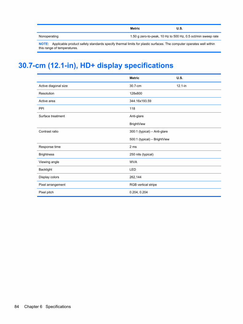
Metric U.S.
Nonoperating 1.50 g zero-to-peak, 10 Hz to 500 Hz, 0.5 oct/min sweep rate
NOTE: Applicable product safety standards specify thermal limits for plastic surfaces. The computer operates well withinthis range of temperatures.
30.7-cm (12.1-in), HD+ display specifications
Metric U.S.
Active diagonal size 30.7-cm 12.1-in
Resolution 128x800
Active area 344.16x193.59
PPI 118
Surface treatment Anti-glare
BrightView
Contrast ratio 300:1 (typical) – Anti-glare
500:1 (typical) – BrightView
Response time 2 ms
Brightness 250 nits (typical)
Viewing angle WVA
Backlight LED
Display colors 262,144
Pixel arrangement RGB vertical stripe
Pixel pitch 0.204, 0.204
84 Chapter 6 Specifications

Hard drive specifications
750-GB* 640-GB* 500-GB* 320-GB* 250-GB*
Dimensions
Height 9.5 mm 9.5 mm 9.5 mm 9.5 mm 9.5 mm
Width 70 mm 70 mm 70 mm 70 mm 70 mm
Weight 115 g 101 g 101 g 101 g 101 g
Interface type SATA SATA SATA SATA SATA
Transfer rate 100 MB/sec 100 MB/sec 100 MB/sec 100 MB/sec 100 MB/sec
Security ATA security ATA security ATA security ATA security ATA security
Seek times (typical read, including setting)
Single track 1.5 ms 2 ms 3 ms 3 ms 3 ms
Average 11 ms 12 ms 13 ms 13 ms 13 ms
Maximum 14 ms 22 ms 24 ms 24 ms 24 ms
Logical blocks 1,465,149,168 1,250,263,728 1,048,576,000 625,141,400 488,397,168
Disc rotational speed 7200 rpm 7200 rpm or 5400 rpm
Operating temperature 5°C to 55°C (41°F to 131°F)
*1 GB = 1 billion bytes when referring to hard drive storage capacity. Actual accessible capacity is less. Actual drivespecifications may differ slightly.
NOTE: Certain restrictions and exclusions apply. Contact technical support for details.
Hard drive specifications 85

Specification information in Device ManagerDevice Manager allows you to view and control the hardware attached to the computer, as well asprovides hardware specification information.
You can also add hardware or modify device configurations using Device Manager.
NOTE: Windows 7 and Windows Vista include the User Account Control feature to improve thesecurity of your computer. You may be prompted for your permission or password for tasks such asinstalling software, running utilities, or changing Windows settings. Refer to Windows Help andSupport for more information.
After you open Device Manager, drill-down to a device and double-click it to access its properties.
To access Device Manager in Windows 7:
1. Select Start > Computer > System properties.
2. In the left pane, click Device Manager.
To access Device Manager in Windows Vista:
1. Select Start > Computer > System properties.
2. In the left pane, click Device Manager.
To access Device Manager in Windows XP:
1. Select Start > My Computer.
2. In the left pane of the System Tasks window, select View system information.
3. Select Hardware tab > Device Manager.
86 Chapter 6 Specifications
7 Backup and recovery
Windows 7● Backing up your information
● Performing a system recovery
To protect your information, use Windows Backup and Restore to back up individual files and folders,back up your entire hard drive (select models only), create system repair discs (select models only)by using the installed optical drive (select models only) or an optional external optical drive, or createsystem restore points. In case of system failure, you can use the backup files to restore the contentsof your computer.
Windows Backup and Restore provides the following options:
● Creating a system repair disc (select models only) by using the installed optical drive (selectmodels only) or an optional external optical drive
● Backing up your information
● Creating a system image (select models only)
● Scheduling automatic backups (select models only)
● Creating system restore points
● Recovering individual files
● Restoring the computer to a previous state
● Recovering information using recovery tools
NOTE: For detailed instructions, perform a search for these topics in Help and Support.
In case of system instability, HP recommends that you print the recovery procedures and save themfor later use.
NOTE: Windows includes the User Account Control feature to improve the security of yourcomputer. You may be prompted for your permission or password for tasks such as installingsoftware, running utilities, or changing Windows settings. Refer to Help and Support for moreinformation.
Backing up your information
Recovery after a system failure is as good as your most recent backup. You should create systemrepair discs (select models only) by using the installed optical drive (select models only) or anoptional external optical drive, and your initial backup immediately after software setup. As you add
Windows 7 87
new software and data files, you should continue to back up your system on a regular basis tomaintain a reasonably current backup. The system repair discs (select models only) are used to startup (boot) the computer and repair the operating system in case of system instability or failure. Yourinitial and subsequent backups allow you to restore your data and settings if a failure occurs.
You can back up your information to an optional external hard drive, a network drive, or discs.
Note the following when backing up:
● Store personal files in the Documents library, and back it up regularly.
● Back up templates that are stored in their associated programs.
● Save customized settings that appear in a window, toolbar, or menu bar by taking a screen shotof your settings. The screen shot can be a time-saver if you have to reset your preferences.
● When backing up to discs, use any of the following types of discs (purchased separately): CD-R,CD-RW, DVD+R, DVD+R DL, DVD-R, DVD-R DL, or DVD±RW. The discs you use will dependon the type of optical drive installed in your computer or the type of external optical drive you areusing.
NOTE: DVDs and DVDs with double-layer (DL) support store more information than CDs, sousing them for backup reduces the number of recovery discs required.
● When backing up to discs, number each disc before inserting it into the optical drive of thecomputer.
To create a backup using Backup and Restore:
NOTE: Be sure that the computer is connected to AC power before you start the backup process.
NOTE: The backup process may take over an hour, depending on file size and the speed of thecomputer.
1. Select Start > All Programs > Maintenance > Backup and Restore.
2. Follow the on-screen instructions to set up your backup, create a system image (select modelsonly), or create a system repair disc (select models only).
Performing a system recovery
In case of system failure or instability, the computer provides the following tools to recover your files:
● Windows recovery tools: You can use Windows Backup and Restore to recover information youhave previously backed up. You can also use Windows Startup Repair to fix problems that mightprevent Windows from starting correctly.
● f11 recovery tools: You can use the f11 recovery tools to recover your original hard drive image.The image includes the Windows operating system and software programs installed at thefactory.
NOTE: If you are unable to boot (start up) your computer and you cannot use the system repairdiscs you previously created (select models only), you must purchase a Windows 7 operating systemDVD to reboot the computer and repair the operating system. For additional information, refer toUsing a Windows 7 operating system DVD (purchased separately) on page 90.
88 Chapter 7 Backup and recovery

Using the Windows recovery tools
To recover information you previously backed up:
1. Select Start > All Programs > Maintenance > Backup and Restore.
2. Follow the on-screen instructions to recover your system settings, your computer (select modelsonly), or your files.
To recover your information using Startup Repair, follow these steps:
CAUTION: Using Startup Repair completely erases hard drive contents and reformats the harddrive. All files you have created and any software installed on the computer are permanentlyremoved. When reformatting is complete, the recovery process restores the operating system, as wellas the drivers, software, and utilities from the backup used for recovery.
1. If possible, back up all personal files.
2. If possible, check for the presence of the Windows partition and the HP Recovery partition.
To check for the Windows partition, select Start > Computer.
To check for the HP Recovery partition, click Start, right-click Computer, click Manage, andthen click Disk Management.
NOTE: If the Windows partition and the HP Recovery partition are not listed, you must recoveryour operating system and programs using the Windows 7 operating system DVD and the DriverRecovery disc (both purchased separately). For additional information, refer to Using a Windows7 operating system DVD (purchased separately) on page 90.
3. If the Windows partition and the HP Recovery partition are listed, restart the computer, and thenpress f8 before the Windows operating system loads.
4. Select Startup Repair.
5. Follow the on-screen instructions.
NOTE: For additional information on recovering information using the Windows tools, perform asearch for these topics in Help and Support.
Using f11 recovery tools
CAUTION: Using f11 completely erases hard drive contents and reformats the hard drive. All filesyou have created and any software installed on the computer are permanently removed. The f11recovery tool reinstalls the operating system and HP programs and drivers that were installed at thefactory. Software not installed at the factory must be reinstalled.
To recover the original hard drive image using f11:
1. If possible, back up all personal files.
2. If possible, check for the presence of the HP Recovery partition: click Start, right-clickComputer, click Manage, and then click Disk Management.
NOTE: If the HP Recovery partition is not listed, you must recover your operating system andprograms using the Windows 7 operating system DVD and the Driver Recovery disc (bothpurchased separately). For additional information, refer to Using a Windows 7 operating systemDVD (purchased separately) on page 90.
Windows 7 89

3. If the HP Recovery partition is listed, restart the computer, and then press esc while the “Pressthe ESC key for Startup Menu” message is displayed at the bottom of the screen.
4. Press f11 while the “Press <F11> for recovery” message is displayed on the screen.
5. Follow the on-screen instructions.
Using a Windows 7 operating system DVD (purchased separately)
To order a Windows 7 operating system DVD, go to http://www.hp.com/support, select your countryor region, and follow the on-screen instructions. You can also order the DVD by calling technicalsupport. For contact information, refer to the Worldwide Telephone Numbers booklet included withthe computer.
CAUTION: Using a Windows 7 operating system DVD completely erases hard drive contents andreformats the hard drive. All files you have created and any software installed on the computer arepermanently removed. When reformatting is complete, the recovery process helps you restore theoperating system, as well as drivers, software, and utilities.
To initiate recovery using a Windows 7 operating system DVD:
NOTE: This process takes several minutes.
1. If possible, back up all personal files.
2. Restart the computer, and then insert the Windows 7 operating system DVD into the opticaldrive before the Windows operating system loads.
3. When prompted, press any keyboard key.
4. Follow the on-screen instructions.
5. Click Next.
6. Select Repair your computer.
7. Follow the on-screen instructions.
90 Chapter 7 Backup and recovery

Windows VistaTo protect your information, use the Backup and Restore Center to back up individual files andfolders, back up your entire hard drive (select models only), or create system restore points. In caseof system failure, you can use the backup files to restore the contents of your computer.
The Backup and Restore Center provides the following options:
● Backing up individual files and folders
● Backing up the entire hard drive (select models only)
● Scheduling automatic backups (select models only)
● Creating system restore points
● Recovering individual files
● Restoring the computer to a previous state
● Recovering information using recovery tools
NOTE: For detailed instructions, perform a search for these topics in Help and Support.
NOTE: In case of system instability, HP recommends that you print the recovery procedures andsave them for later use.
NOTE: Windows® includes the User Account Control feature to improve the security of yourcomputer. You may be prompted for your permission or password for tasks such as installingsoftware, running utilities, or changing Windows settings. Refer to Help and Support for moreinformation.
Backing up your information
Recovery after a system failure is as complete as your most current backup. You should create yourinitial backup immediately after software setup. As you add new software and data files, you shouldcontinue to back up your system on a regular basis to maintain a reasonably current backup.
You can back up your information to an optional external hard drive, a network drive, or discs.
Note the following when backing up:
● Store personal files in the Documents folder, and back it up regularly.
● Back up templates that are stored in their associated programs.
● Save customized settings that appear in a window, toolbar, or menu bar by taking a screen shotof your settings. The screen shot can be a time-saver if you have to reset your preferences.
● When backing up to discs, use any of the following types of discs (purchased separately): CD-R,CD-RW, DVD+R, DVD+R DL, DVD-R, DVD-R DL, or DVD±RW. The discs you use will dependon the type of optical drive installed in your computer.
NOTE: DVDs and DVDs with double-layer (DL) support store more information than CDs, sousing them for backup reduces the number of recovery discs required.
● When backing up to discs, number each disc before inserting it into the optical drive of thecomputer.
Windows Vista 91

To create a backup using Backup and Restore Center:
NOTE: Be sure that the computer is connected to AC power before you start the backup process.
NOTE: The backup process may take over an hour, depending on file size and the speed of thecomputer.
1. Select Start > All Programs > Maintenance > Backup and Restore Center.
2. Follow the on-screen instructions to back up your entire computer (select models only) or yourfiles.
Performing a recovery
In case of system failure or instability, the computer provides the following tools to recover your files:
● Windows recovery tools: You can use the Backup and Restore Center to recover informationyou have previously backed up. You can also use Windows Startup Repair to fix problems thatmight prevent Windows from starting correctly.
● f11 recovery tools: You can use the f11 recovery tools to recover your original hard drive image.The image includes the Windows operating system and software programs installed at thefactory.
NOTE: If you are unable to boot (start up) your computer, you must purchase a Windows Vista®operating system DVD to reboot the computer and repair the operating system. For additionalinformation, refer to Using a Windows Vista operating system DVD (purchased separately)on page 93.
Using the Windows recovery tools
To recover information you previously backed up:
1. Select Start > All Programs > Maintenance > Backup and Restore Center.
2. Follow the on-screen instructions to recover your entire computer (select models only) or yourfiles.
To recover your information using Startup Repair, follow these steps:
CAUTION: Using Startup Repair completely erases hard drive contents and reformats the harddrive. All files you have created and any software installed on the computer are permanentlyremoved. When reformatting is complete, the recovery process restores the operating system, as wellas the drivers, software, and utilities from the backup used for recovery.
1. If possible, back up all personal files.
2. If possible, check for the presence of the Windows partition and the HP Recovery partition. Tofind the partitions, select Start > Computer.
NOTE: If the Windows partition and the HP Recovery partition have been deleted, you mustrecover your operating system and programs using the Windows Vista operating system DVDand the Driver Recovery disc (both purchased separately). For additional information, refer toUsing a Windows Vista operating system DVD (purchased separately) on page 93.
3. Restart the computer, and then press f8 before the Windows operating system loads.
92 Chapter 7 Backup and recovery

4. Select Repair your computer.
5. Follow the on-screen instructions.
NOTE: For additional information on recovering information using the Windows tools, perform asearch for these topics in Help and Support.
Using f11 recovery tools
CAUTION: Using f11 completely erases hard drive contents and reformats the hard drive. All filesyou have created and any software installed on the computer are permanently removed. The f11recovery tool reinstalls the operating system and HP programs and drivers that were installed at thefactory. Software not installed at the factory must be reinstalled. Personal files must be restored froma backup.
NOTE: If your computer includes a solid-state drive (SSD), you may not have a recovery partition.Recovery discs have been included for computers that do not have a partition. Use these discs torecover your operating system and software. To check for the presence of a recovery partition, selectStart > Computer. If the partition is present, an HP Recovery drive is listed in the Hard Disk Drivessection of the window.
To recover the original hard drive image using f11, follow these steps:
1. If possible, back up all personal files.
2. If possible, check for the presence of the HP Recovery partition. To find the partition, selectStart > Computer.
NOTE: If the HP Recovery partition has been deleted, you must recover your operating systemand programs using the Windows Vista operating system DVD and the Driver Recovery disc(both purchased separately). For additional information, refer to Using a Windows Vistaoperating system DVD (purchased separately) on page 93.
3. Turn on or restart the computer, and then press esc while the “Press the ESC key for StartupMenu” message is displayed at the bottom of the screen.
4. Press f11 while the “Press <F11> for recovery” message is displayed on the screen.
5. Follow the on-screen instructions.
Using a Windows Vista operating system DVD (purchased separately)
To order a Windows Vista operating system DVD, go to http://www.hp.com/support, select yourcountry or region, and follow the on-screen instructions. You can also order the DVD by callingtechnical support. For contact information, refer to the Worldwide Telephone Numbers bookletincluded with the computer.
CAUTION: Using a Windows Vista operating system DVD completely erases hard drive contentsand reformats the hard drive. All files you have created and any software installed on the computerare permanently removed. When reformatting is complete, the recovery process helps you restore theoperating system, as well as drivers, software, and utilities.
To initiate recovery using a Windows Vista operating system DVD:
Windows Vista 93

NOTE: This process takes several minutes.
1. If possible, back up all personal files.
2. Restart the computer, and then insert the Windows Vista operating system DVD into the opticaldrive before the Windows operating system loads.
3. When prompted, press any keyboard key.
4. Follow the on-screen instructions.
5. Click Next.
6. Select Repair your computer.
7. Follow the on-screen instructions.
94 Chapter 7 Backup and recovery

8 Power cord set requirements
The wide range input feature of the computer permits it to operate from any line voltage from 100 to120 volts AC, or from 220 to 240 volts AC.
The 3-conductor power cord set included with the computer meets the requirements for use in thecountry or region where the equipment is purchased.
Power cord sets for use in other countries and regions must meet the requirements of the country orregion where the computer is used.
Requirements for all countries and regionsThe requirements listed below are applicable to all countries and regions:
● The length of the power cord set must be at least 1.5 m (5.0 ft) and no more than 2.0 m (6.5 ft).
● All power cord sets must be approved by an acceptable accredited agency responsible forevaluation in the country or region where the power cord set will be used.
● The power cord sets must have a minimum current capacity of 10 amps and a nominal voltagerating of 125 or 250 V AC, as required by the power system of each country or region.
● The appliance coupler must meet the mechanical configuration of an EN 60 320/IEC 320Standard Sheet C13 connector for mating with the appliance inlet on the back of the computer.
Requirements for all countries and regions 95

Requirements for specific countries and regions
Country/region Accredited agency Applicable note number
Australia EANSW 1
Austria OVE 1
Belgium CEBC 1
Canada CSA 2
Denmark DEMKO 1
Finland FIMKO 1
France UTE 1
Germany VDE 1
Italy IMQ 1
Japan METI 3
The Netherlands KEMA 1
Norway NEMKO 1
The People's Republic of China CCC 5
South Korea EK 4
Sweden SEMKO 1
Switzerland SEV 1
Taiwan BSMI 4
The United Kingdom BSI 1
The United States UL 2
1. The flexible cord must be Type HO5VV-F, 3-conductor, 1.0-mm² conductor size. Power cord set fittings (appliancecoupler and wall plug) must bear the certification mark of the agency responsible for evaluation in the country or regionwhere it will be used.
2. The flexible cord must be Type SPT-3 or equivalent, No. 18 AWG, 3-conductor. The wall plug must be a two-polegrounding type with a NEMA 5-15P (15 A, 125 V) or NEMA 6-15P (15 A, 250 V) configuration.
3. The appliance coupler, flexible cord, and wall plug must bear a “T” mark and registration number in accordance with theJapanese Dentori Law. The flexible cord must be Type VCT or VCTF, 3-conductor, 1.00-mm² conductor size. The wallplug must be a two-pole grounding type with a Japanese Industrial Standard C8303 (7 A, 125 V) configuration.
4. The flexible cord must be Type RVV, 3-conductor, 0.75-mm² conductor size. Power cord set fittings (appliance couplerand wall plug) must bear the certification mark of the agency responsible for evaluation in the country or region where itwill be used.
5. The flexible cord must be Type VCTF, 3-conductor, 0.75-mm² conductor size. Power cord set fittings (appliance couplerand wall plug) must bear the certification mark of the agency responsible for evaluation in the country or region where itwill be used.
96 Chapter 8 Power cord set requirements
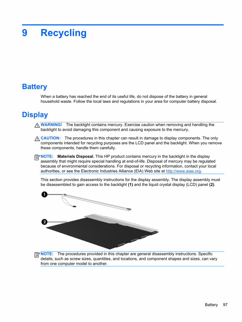
9 Recycling
BatteryWhen a battery has reached the end of its useful life, do not dispose of the battery in generalhousehold waste. Follow the local laws and regulations in your area for computer battery disposal.
DisplayWARNING! The backlight contains mercury. Exercise caution when removing and handling thebacklight to avoid damaging this component and causing exposure to the mercury.
CAUTION: The procedures in this chapter can result in damage to display components. The onlycomponents intended for recycling purposes are the LCD panel and the backlight. When you removethese components, handle them carefully.
NOTE: Materials Disposal. This HP product contains mercury in the backlight in the displayassembly that might require special handling at end-of-life. Disposal of mercury may be regulatedbecause of environmental considerations. For disposal or recycling information, contact your localauthorities, or see the Electronic Industries Alliance (EIA) Web site at http://www.eiae.org.
This section provides disassembly instructions for the display assembly. The display assembly mustbe disassembled to gain access to the backlight (1) and the liquid crystal display (LCD) panel (2).
NOTE: The procedures provided in this chapter are general disassembly instructions. Specificdetails, such as screw sizes, quantities, and locations, and component shapes and sizes, can varyfrom one computer model to another.
Battery 97

Perform the following steps to disassemble the display assembly:
1. Remove all screw covers (1) and screws (2) that secure the display bezel to the displayassembly.
2. Lift up and out on the left and right inside edges (1) and the top and bottom inside edges (2) ofthe display bezel until the bezel disengages from the display assembly.
3. Remove the display bezel (3).
98 Chapter 9 Recycling
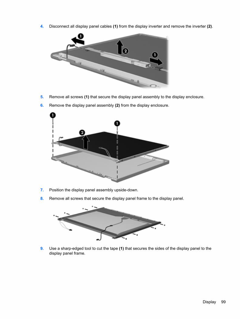
4. Disconnect all display panel cables (1) from the display inverter and remove the inverter (2).
5. Remove all screws (1) that secure the display panel assembly to the display enclosure.
6. Remove the display panel assembly (2) from the display enclosure.
7. Position the display panel assembly upside-down.
8. Remove all screws that secure the display panel frame to the display panel.
9. Use a sharp-edged tool to cut the tape (1) that secures the sides of the display panel to thedisplay panel frame.
Display 99
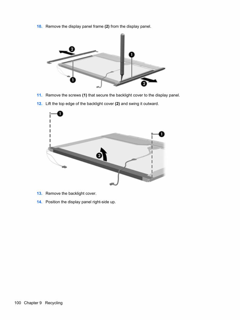
10. Remove the display panel frame (2) from the display panel.
11. Remove the screws (1) that secure the backlight cover to the display panel.
12. Lift the top edge of the backlight cover (2) and swing it outward.
13. Remove the backlight cover.
14. Position the display panel right-side up.
100 Chapter 9 Recycling

15. Remove the backlight cables (1) from the clip (2) in the display panel.
16. Position the display panel upside-down.
WARNING! The backlight contains mercury. Exercise caution when removing and handling thebacklight to avoid damaging this component and causing exposure to the mercury.
17. Remove the backlight frame from the display panel.
Display 101

18. Remove the backlight from the backlight frame.
19. Disconnect the display panel cable (1) from the LCD panel.
20. Remove the screws (2) that secure the LCD panel to the display rear panel.
21. Release the LCD panel (3) from the display rear panel.
22. Release the tape (4) that secures the LCD panel to the display rear panel.
23. Remove the LCD panel.
24. Recycle the LCD panel and backlight.
102 Chapter 9 Recycling

Index
AAC adapter light 15AC adapter, spare part numbers
27access cover release latches 16access door
removal 43spare part number 24, 33, 43
access door, identifying 16antennas
disconnecting 48, 52audio, product description 2audio-in (microphone) jack 13audio-out (headphone) jack 13
BBackup and Restore 88Backup and Restore Center 91,
92base enclosure, spare part
number 24, 32battery
removal 41spare part number 23, 41
battery bay 16battery release latches 16BIOS
determining version 81downloading an update 81updating 81
Bluetooth cardspare part number 49
Bracket Kit, spare part number25, 33, 64, 73
buttonsleft TouchPad 8power 10right TouchPad 8
TouchPad on/off 8wireless 11
CCable Kit
contents 26spare part number 26
cables, service considerations 35caps lock light, identifying 9chipset, product description 1components
bottom 16display 7front 13left side 14right side 15top 8
computer feetlocations 40spare part number 40
Computer Setupnavigating and selecting 79restoring factory settings 80
computer specifications 83connector, power 15connectors, service
considerations 35
Ddiskette drive
precautions 35display assembly
removal 74spare part numbers 74
display bezelremoval 75spare part numbers 24, 32
display component recycling 97
display components, spare partnumbers 24
display enclosure, spare partnumber 25
display hingeremoval 77
display hinge coverspare part numbers 24, 33
Display Hinge Kitspare part number 24
display panelproduct description 1removal 76
display specifications 84drive light 13drives
preventing damage 35DVD-ROM Drive
precautions 35DVD±RW and CD-RW SuperMulti
DL Combo Drive with LightScribeprecautions 35
Eelectrostatic discharge 36embedded numeric keypad,
identifying 12esc key, identifying 12Ethernet, product description 3external media cards, product
description 3
Ff11 recovery 89, 93fan
removal 67spare part number 19, 32, 67
Index 103

feetlocations 40spare part number 40
fingerprint reader, identifying 11fn key, identifying 12function keys, identifying 12
Ggraphics, product description 1grounding equipment and
methods 38
Hhard drive
precautions 35product description 2removal 44spare part number 31spare part numbers 23, 26,
31, 44specifications 85
hard drive bracket, removal 45hard drive cable, illustrated 26Hard Drive Hardware Kit, spare
part number 26, 33, 44hard drive recovery 89, 93HDMI port, identifying 14heat sink
removal 69spare part number 19, 69
hingeremoval 77
Iintegrated webcam light,
identifying 7internal microphones, identifying
7
Jjacks
audio-in (microphone) 13audio-out (headphone) 13network 15RJ-11 (modem) 14RJ-45 (network) 15
Kkeyboard
product description 4
removal 54spare part numbers 18, 32, 54
keypad, embedded numeric 12keys
esc 12fn 12function 12menu 12num lk 12start 12
Llatches
access cover 16battery 16
legacy support, USB 79lights
AC adapter 15caps lock 9drive 13power 9QuickWeb 9, 11webcam 7wireless 9
Mmass storage devices, spare part
numbers 26Media Card Reader, identifying
13memory module
product description 2removal 46spare part numbers 23, 46
menu key, identifying 12microphone (audio-in) jack
product description 2microphone module
spare part number 32model name 1modem module
product description 2removal 61spare part number 19, 29, 61
monitor port, external 14
Nnetwork jack, identifying 15num lk key, identifying 12
Ooperating system, product
description 4optical drive
precautions 35
Ppacking guidelines 37plastic parts 34Plastics Kit, spare part number
25, 33pointing device, product
description 4ports
external monitor 14HDMI 14product description 3USB 14, 15USB charging 15
power button boardremoval 60spare part number 19, 33, 60
power button, identifying 10power connector, identifying 15power cord
set requirements 95spare part numbers 27, 28
power light 9power requirements, product
description 4processor
product description 1removal 71spare part numbers 19, 71
product descriptionaudio 2chipset 1display panel 1Ethernet 3external media cards 3graphics 1hard drives 2keyboard 4memory module 2microphone 2modem module 2operating system 4pointing devices 4ports 3power requirements 4
104 Index

processors 1product name 1security 4serviceability 5webcam 2wireless 3
product name 1
QQuick Launch board
removal 59spare part number 19, 33, 59
QuickWeb light 9QuickWeb light, identifying 11
Rrecovery partition 89, 93removal/replacement
preliminaries 34procedures 39
restoring the hard drive 89, 93RJ-11 (modem) jack, identifying
14RJ-11 connector cable
illustrated 26RJ-11 holder, illustrated
illustrated 25RJ-11 jack cable
removal 73RJ-45 (network) jack, identifying
15RTC battery
removal 65spare part number 23, 33, 65
Rubber Kit, spare part number 33
SScrew Kit, spare part number 27,
33Secure Digital card insert,
illustrated 25security cable slot 14security, product description 4service considerations 34service tag 17, 39serviceability, product
description 5setup utility
navigating and selecting 79restoring factory settings 80
SIM protective insertillustrated 25
SIM slot, identifying 16SIM, removal 42slots
security cable 14SIM 16
speaker assemblyremoval 62spare part number 19, 33, 62
speakers, identifying 13specifications
computer 83display 84hard drive 85
start key, identifying 12static-shielding materials 38system board
removal 63spare part numbers 19, 33,
63system repair disc 87system restore points 87
Tthermal material, replacement 70tools required 34top cover
removal 55spare part number 18, 55spare part numbers 33
TouchPadbuttons 8identifying 8on/off button 8
transporting guidelines 37
UUSB legacy support 79USB port, identifying 14USB ports, identifying 15
Vvents, identifying 14, 16
Wwebcam 8
identifying 8product description 2spare part number 24, 32
webcam light, identifying 7
Windows 7 operating systemDVD 90
Windows Backup and Restore 87Windows Vista operating system
DVD 93wireless antennas
disconnecting 48, 52identifying 7
wireless button, identifying 11wireless light 9wireless, product description 3WLAN antennas
identifying 7spare part number 24, 32
WLAN modulespare part number 28spare part numbers 20
WLAN/Bluetooth combo cardremoval 49spare part number 49
workstation guidelines 37WWAN antennas
identifying 7spare part number 24, 32
WWAN moduleremoval 47spare part number 20, 47
Index 105