MAIN SECTION Page 1 of 253 1 of 1 Section · component/ system fault code monitor strategy...
253
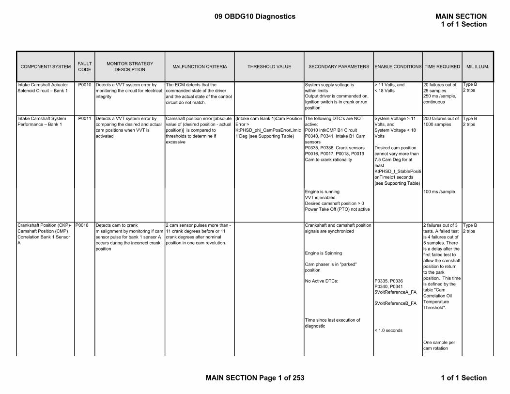
COMPONENT/ SYSTEM FAULT CODE MONITOR STRATEGY DESCRIPTION MALFUNCTION CRITERIA THRESHOLD VALUE SECONDARY PARAMETERS ENABLE CONDITIONS TIME REQUIRED MIL ILLUM. System supply voltage is within limits > 11 Volts, and < 18 Volts 20 failures out of 25 samples Type B 2 trips Output driver is commanded on, Ignition switch is in crank or run position 250 ms /sample, continuous The following DTC’s are NOT active: P0010 IntkCMP B1 Circuit P0340, P0341, Intake B1 Cam sensors P0335, P0336, Crank sensors P0016, P0017, P0018, P0019 Cam to crank rationality System Voltage > 11 Volts, and System Voltage < 18 Volts Desired cam position cannot vary more than 7.5 Cam Deg for at least KtPHSD_t_StablePositi onTimeIc1 seconds (see Supporting Table) 200 failures out of 1000 samples Type B 2 trips (Intake cam Bank 1)Cam Position Error > KtPHSD_phi_CamPosErrorLimIc 1 Deg (see Supporting Table) Intake Camshaft System Performance – Bank 1 P0011 Detects a VVT system error by comparing the desired and actual cam positions when VVT is activated Camshaft position error [absolute value of (desired position - actual position)] is compared to thresholds to determine if excessive Intake Camshaft Actuator Solenoid Circuit – Bank 1 P0010 Detects a VVT system error by monitoring the circuit for electrical integrity The ECM detects that the commanded state of the driver and the actual state of the control circuit do not match. (see Supporting Table) Engine is running VVT is enabled Desired camshaft position > 0 Power Take Off (PTO) not active 100 ms /sample Engine is Spinning No Active DTCs: P0335, P0336 P0340, P0341 5VoltReferenceA_FA 5VoltReferenceB_FA Detects cam to crank misalignment by monitoring if cam sensor pulse for bank 1 sensor A occurs during the incorrect crank position Type B 2 trips Cam phaser is in "parked" position One sample per cam rotation Time since last execution of diagnostic < 1.0 seconds 2 failures out of 3 tests. A failed test is 4 failures out of 5 samples. There is a delay after the first failed test to allow the camshaft position to return to the park position. This time is defined by the table "Cam Correlation Oil Temperature Threshold". Crankshaft and camshaft position signals are synchronized 2 cam sensor pulses more than - 11 crank degrees before or 11 crank degrees after nominal position in one cam revolution. Crankshaft Position (CKP)- Camshaft Position (CMP) Correlation Bank 1 Sensor A P0016 09 OBDG10 Diagnostics MAIN SECTION 1 of 1 Section MAIN SECTION Page 1 of 253 1 of 1 Section
Transcript of MAIN SECTION Page 1 of 253 1 of 1 Section · component/ system fault code monitor strategy...
COMPONENT/ SYSTEM FAULT CODE
MONITOR STRATEGY DESCRIPTION MALFUNCTION CRITERIA THRESHOLD VALUE SECONDARY PARAMETERS ENABLE CONDITIONS TIME REQUIRED MIL ILLUM.
System supply voltage iswithin limits
> 11 Volts, and < 18 Volts
20 failures out of 25 samples
Type B2 trips
Output driver is commanded on, Ignition switch is in crank or run position
250 ms /sample, continuous
The following DTC’s are NOT active: P0010 IntkCMP B1 CircuitP0340, P0341, Intake B1 Cam sensorsP0335, P0336, Crank sensorsP0016, P0017, P0018, P0019 Cam to crank rationality
System Voltage > 11 Volts, and System Voltage < 18 Volts
Desired cam position cannot vary more than 7.5 Cam Deg for at least KtPHSD_t_StablePositionTimeIc1 seconds (see Supporting Table)
200 failures out of 1000 samples
Type B2 trips
(Intake cam Bank 1)Cam Position Error > KtPHSD_phi_CamPosErrorLimIc1 Deg (see Supporting Table)
Intake Camshaft System Performance – Bank 1
P0011 Detects a VVT system error by comparing the desired and actual cam positions when VVT is activated
Camshaft position error [absolute value of (desired position - actual position)] is compared to thresholds to determine if excessive
Intake Camshaft Actuator Solenoid Circuit – Bank 1
P0010 Detects a VVT system error by monitoring the circuit for electrical integrity
The ECM detects that the commanded state of the driver and the actual state of the control circuit do not match.
(see Supporting Table)
Engine is runningVVT is enabledDesired camshaft position > 0Power Take Off (PTO) not active
100 ms /sample
Engine is Spinning
No Active DTCs: P0335, P0336P0340, P03415VoltReferenceA_FA
5VoltReferenceB_FA
Detects cam to crank misalignment by monitoring if cam sensor pulse for bank 1 sensor A occurs during the incorrect crank position
Type B2 trips
Cam phaser is in "parked" position
One sample per cam rotation
Time since last execution of diagnostic
< 1.0 seconds
2 failures out of 3 tests. A failed test is 4 failures out of 5 samples. There is a delay after the first failed test to allow the camshaft position to return to the park position. This time is defined by the table "Cam Correlation Oil Temperature Threshold".
Crankshaft and camshaft position signals are synchronized
2 cam sensor pulses more than -11 crank degrees before or 11 crank degrees after nominal position in one cam revolution.
Crankshaft Position (CKP)-Camshaft Position (CMP) Correlation Bank 1 Sensor A
P0016
09 OBDG10 Diagnostics MAIN SECTION1 of 1 Section
MAIN SECTION Page 1 of 253 1 of 1 Section

COMPONENT/ SYSTEM FAULT CODE
MONITOR STRATEGY DESCRIPTION MALFUNCTION CRITERIA THRESHOLD VALUE SECONDARY PARAMETERS ENABLE CONDITIONS TIME REQUIRED MIL ILLUM.
Output driver is commanded on, Ignition switch is in crank or run position
250 ms /sample, continuous
Ign Switch position= Crank or Run position
Engine Speed > 400 RPM
Continuous
Ign Switch position= Crank or Run position
Type B2 trips
20 failures out of 25 samples
250 ms /sampleIgnition Voltage
11.0 volts < Ign Voltage < 18.0 volts
Type B2 trips
20 failures out of 25 samples
Voltage low during driver open state (indicates short-to-ground or open circuit) or voltage high during driver closed state (indicates short to voltage).
O2S Heater Control Circuit Bank 1 Sensor 1
P0030 This DTC checks the Heater Output Driver circuit for electrical integrity.
O2S Heater Control Circuit Bank 1 Sensor 2
P0036
11 0 volts < Ign Voltage
This DTC checks the Heater Output Driver circuit for electrical i t it
Voltage low during driver open state (indicates short-to-ground or
i it) lt hi h
Engine Speed > 400 RPM
Continuous
Ign Switch position= Crank or Run position
Engine Speed > 400 RPM
Continuous
Ign Switch position= Crank or Run position
Engine Speed > 400 RPM
Continuous
20 failures out of 25 samples
Type B2 trips
Voltage low during driver open state (indicates short-to-ground or open circuit) or voltage high during driver closed state (indicates short to voltage).
Ignition Voltage
Type B2 trips
250 ms /sample
20 failures out of 25 samples
O2S Heater Control Circuit Bank 2 Sensor 1
P0050 This DTC checks the Heater Output Driver circuit for electrical integrity.
Voltage low during driver open state (indicates short-to-ground or open circuit) or voltage high during driver closed state (indicates short to voltage).
O2S Heater Control Circuit Bank 2 Sensor 2
P0056 This DTC checks the Heater Output Driver circuit for electrical integrity.
250 ms /sample
11.0 volts < Ign Voltage < 18.0 voltsIgnition Voltage
11.0 volts < Ign Voltage < 18.0 volts
250 ms /sample
integrity. open circuit) or voltage high during driver closed state (indicates short to voltage).
Ignition Voltage11.0 volts < Ign Voltage < 18.0 volts
09 OBDG10 Diagnostics MAIN SECTION1 of 1 Section
MAIN SECTION Page 2 of 253 1 of 1 Section

COMPONENT/ SYSTEM FAULT CODE
MONITOR STRATEGY DESCRIPTION MALFUNCTION CRITERIA THRESHOLD VALUE SECONDARY PARAMETERS ENABLE CONDITIONS TIME REQUIRED MIL ILLUM.
No Active DTC's ECT_Sensor_FAP2610IAT_SensorFA
Coolant – IAT < 8.0 ºCEngine Soak Time > 28800 seconds
Coolant Temp -30.0 ºC ≤ Coolant ≤ 45.0 ºC
Ignition Voltage < 18.0 volts Engine Run time >= 3.00 seconds
No Active DTC's ECT_Sensor_FAP2610IAT_SensorFA
Coolant – IAT < 8.0 ºCEngine Soak Time > 28800 seconds
Coolant Temp -30.0 ºC ≤ Coolant ≤ 45.0 ºC
Ignition Voltage < 18.0 volts Engine Run time > 3 00 d
Once per valid cold start
Type B2 trips
Detects an oxygen sensor heater having an incorrect or out of range resistance value.
Learned Heater Resistance. Once per valid cold start
Calculated Heater Resistance < 2.8 ohms -OR- Calculated Heater Resistance > 9.5 ohms
HO2S Heater Resistance Bank 1 Sensor 1
P0053 Type B2 trips
Calculated Heater Resistance < 4.1 ohms -OR- Calculated Heater Resistance > 10.8 ohms
HO2S Heater Resistance Bank 1 Sensor 2
P0054 Detects an oxygen sensor heater having an incorrect or out of range resistance value.
Learned Heater Resistance.
Engine Run time >= 3.00 seconds
No Active DTC's ECT_Sensor_FAP2610IAT_SensorFA
Coolant – IAT < 8.0 ºCEngine Soak Time > 28800 seconds
Coolant Temp -30.0 ºC ≤ Coolant ≤ 45.0 ºC
Ignition Voltage < 18.0 volts Engine Run time >= 3.00 seconds
No Active DTC's ECT_Sensor_FAP2610IAT_SensorFA
Coolant – IAT < 8.0 ºCEngine Soak Time > 28800 seconds
Coolant Temp -30.0 ºC ≤ Coolant ≤ 45.0 ºC
Ignition Voltage < 18.0 volts Engine Run time >= 3.00 seconds
Engine Speed > 800 RPM Continuously fail MAP and MAF portions of diagnostic for 0.1875 ms
MAP / MAF / Throttle Position Correlation
P0068 Detect when MAP and MAF do not match estimated engine airflow as established by the TPS
1) Difference between measured MAP and estimated MAP exceeds threshold (kPa), or P0651 (5 Volt Ref), or P0107 (MAP circuit low), or P0108 (MAP circuit high) have
Table, f(TPS). See supporting tables
Type B2 trips
Calculated Heater Resistance < 4.1 ohms -OR- Calculated Heater Resistance > 10.8 ohms
Once per valid cold start
Detects an oxygen sensor heater having an incorrect or out of range resistance value.
Type B2 trips
HO2S Heater Resistance Bank 2 Sensor 2
P0060 Detects an oxygen sensor heater having an incorrect or out of range resistance value.
Learned Heater Resistance. Calculated Heater Resistance < 0.0 ohms -OR- Calculated Heater Resistance > 0.0 ohms
Once per valid cold start
HO2S Heater Resistance Bank 2 Sensor 1
P0059 Learned Heater Resistance.
Type A 1 trip
09 OBDG10 Diagnostics MAIN SECTION1 of 1 Section
MAIN SECTION Page 3 of 253 1 of 1 Section

COMPONENT/ SYSTEM FAULT CODE
MONITOR STRATEGY DESCRIPTION MALFUNCTION CRITERIA THRESHOLD VALUE SECONDARY PARAMETERS ENABLE CONDITIONS TIME REQUIRED MIL ILLUM.
Run/crank voltage or Powertrain relay voltage > 6.00 and reduced power is false, else the failure will be reported for all conditions
Continuous in Primary processor
2) Difference between measured MAF and estimated MAF exceed threshold (grams/sec), or P0102 (MAF circuit low), or P0103 (MAF circuit hi) have failed this key cycle, or battery voltage < 10.0
Table, f(TPS). See supporting tables
( g )failed this key cycle, then MAP portion of diagnostic fails
No Active DTCs:AmbientAirPressCktFAECT_Sensor_Ckt_FA
IAT_SensorFAMAF_SensorFAAfterThrottlePressureFA NATPS_FATPS_Performance_FA
VehicleSpeedSensor_FA
OREngine Run Time > 30.00 seconds
Filtered Throttle Model <= 150 kPa/(g/s) Engine Speed >= 450 RPMAND Engine Speed <= 8000 RPM
Coolant Temp > -7 Deg CCoolant Temp < 125 Deg CIntake Air Temp > -7 Deg C
AND Intake Air Temp < 125 Deg C
> 2025.0 kPa
Type B2 trips
y , y gvolts, then MAF portion of diagnostic fails
> 10 grams/sec
Difference between baro sensor reading and estimated baro
20 failures out of 25 samples
1 sample every 250 msec
Continuous
Calculation are performed every 12.5 msec
Type B2 trips
> 2.00 kilometers
ABS(Measured Flow – Modeled Air Flow) Filtered
Manifold Absolute Pressure -Barometric Pressure Correlation (naturally aspirated applications)
P0069 Compares baro sensor to the calculated baro estimate (part throttle calculation or unthrottled MAP)
Difference between baro sensor reading and estimated baro
when distance since last estimated baro update
when distance since last estimated baro update
> 1015.0 kPa
<= 2.00 kilometers
Mass Air Flow System Performance
P0101 Determines if the MAF sensor is stuck within the normal operating range
09 OBDG10 Diagnostics MAIN SECTION1 of 1 Section
MAIN SECTION Page 4 of 253 1 of 1 Section
COMPONENT/ SYSTEM FAULT CODE
MONITOR STRATEGY DESCRIPTION MALFUNCTION CRITERIA THRESHOLD VALUE SECONDARY PARAMETERS ENABLE CONDITIONS TIME REQUIRED MIL ILLUM.
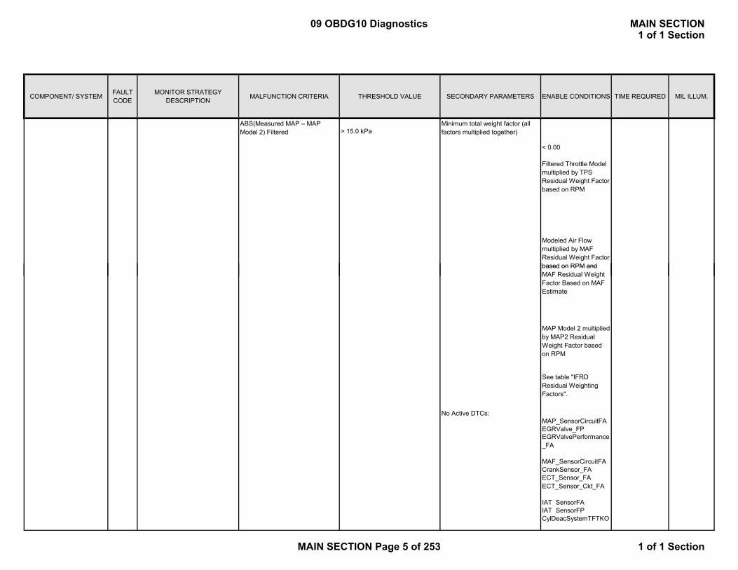
ABS(Measured MAP – MAP Model 2) Filtered > 15.0 kPa
Minimum total weight factor (all factors multiplied together)
< 0.00
Filtered Throttle Model multiplied by TPS Residual Weight Factor based on RPM
Modeled Air Flow multiplied by MAF Residual Weight Factor based on RPM and
No Active DTCs:MAP_SensorCircuitFAEGRValve_FPEGRValvePerformance_FA
MAF_SensorCircuitFACrankSensor_FAECT_Sensor_FAECT_Sensor_Ckt_FA
IAT_SensorFAIAT_SensorFPCylDeacSystemTFTKO
MAP Model 2 multiplied by MAP2 Residual Weight Factor based on RPM
based on RPM and MAF Residual Weight Factor Based on MAF Estimate
See table "IFRD Residual Weighting Factors".
09 OBDG10 Diagnostics MAIN SECTION1 of 1 Section
MAIN SECTION Page 5 of 253 1 of 1 Section

COMPONENT/ SYSTEM FAULT CODE
MONITOR STRATEGY DESCRIPTION MALFUNCTION CRITERIA THRESHOLD VALUE SECONDARY PARAMETERS ENABLE CONDITIONS TIME REQUIRED MIL ILLUM.
MAF Output <= 1126 Hertz Engine Run Time > 1.0 seconds((~0.90 g/s) Engine Speed >= 300 RPM
Ignition Voltage >= 9.0 Volts
MAF Output >= 12450 Hertz Engine Run Time > 1.0 seconds((~ 583 g/s) Engine Speed >= 300 RPM
Ignition Voltage >= 9.0 Volts
Filtered Throttle Model <= 150 kPa/(g/s) Engine Speed >= 450 RPMAND Engine Speed <= 8000 RPM
Coolant Temp > -7 Deg CCoolant Temp < 125 Deg C
AND Intake Air Temp > -7 Deg CIntake Air Temp < 125 Deg C
> 15 0 kPa
Detects a high frequency output from the MAF sensor
ABS(Measured MAP – MAP Model 1) Filtered
Determines if the MAP sensor is stuck within the normal operating range
ABS(Measured MAP – MAP M d l 2) Filt d
Mass Air Flow Sensor Circuit Low Frequency
P0102 Detects a continuous short to low or a open in either the signal circuit or the MAF sensor
Above criteria present for a period of time
Mass Air Flow Sensor Circuit High Frequency
P0103
Manifold Absolute Pressure Sensor Performance
P0106
1 sample every cylinder firing event
1 sample every cylinder firing event
Minimum total weight factor (all
Continuous
Calculations are performed every 12.5 msec
400 failures out of 500 samples
400 failures out of 500 samples
Type B2 trips
> 15.0 kPa
Above criteria present for a period of time
>= 1.0 seconds
>= 1.0 secondsType B2 trips
Type B2 trips
No Active DTCs:MAP_SensorCircuitFAEGRValve_FPEGRValvePerformance_FA
> 15.0 kPaModel 2) Filtered
MAP Model 1 multiplied by MAP1 Residual Weight Factor based on RPM
MAP Model 2 multiplied by MAP2 Residual Weight Factor based on RPM
See table "IFRD Residual Weighting Factors".
< 0.00
Minimum total weight factor (all factors multiplied together)
Filtered Throttle Model multiplied by TPS Residual Weight Factor based on RPM
09 OBDG10 Diagnostics MAIN SECTION1 of 1 Section
MAIN SECTION Page 6 of 253 1 of 1 Section

COMPONENT/ SYSTEM FAULT CODE
MONITOR STRATEGY DESCRIPTION MALFUNCTION CRITERIA THRESHOLD VALUE SECONDARY PARAMETERS ENABLE CONDITIONS TIME REQUIRED MIL ILLUM.
MAF_SensorCircuitFACrankSensorFAECT_sensor_FAECT_Sensor_FPIAT_SensorFAIAT_SensorCircuitFP
CylDeacSystemTFTKO
MAP Voltage Continuous
MAP Voltage Continuous
320 failures out of 400 samples
320 failures out of 400 samples
1 sample every 12.5 msec
Manifold Absolute Pressure Sensor Circuit Low
P0107 Detects a continuous short to low or open in either the signal circuit or the MAP sensor.
Manifold Absolute Pressure Sensor Circuit High
< 3.0 % of 5 Volt Range (0.2 Volts = 3.5 kPa)
P0108 Detects an open sensor ground or continuous short to high in either th i l i it th MAP
> 90.0 % of 5 Volt Range (4.5 Volts = 115.3 kPa)
Type B2 trips
Type B2 trips
Raw IAT Input
Coolant Temp < 150 deg CVehicle Speed >= 0 KPHNo Active DTCs: ECT_Sensor_Ckt_FA
ECT_Sensor_Ckt_FP
VehicleSpeedSensorError
Raw IAT Input
Coolant Temp > -40 deg CVehicle Speed <= 512 KPHEngine Air Flow <= 512 gm/secNo Active DTCs: ECT_Sensor_Ckt_FA
ECT_Sensor_Ckt_FP
VehicleSpeedSensorErrorMAF_SensorFAMAF_SensorFPMAF_SensorTFTKO
< 45 Ohms (~150 deg C)
Intake Air Temperature Sensor Circuit High (Low Temperature)
P0113 Detects an open circuit in the IAT signal circuit or the IAT sensor
> 420000 Ohms (~-60 deg C)
> 10.0 seconds
Engine Run TimeDetects a continuous short to ground in the IAT signal circuit or the IAT sensor
Intake Air Temperature Sensor Circuit Low (High Temperature)
P0112
50 failures out of 63 samples
Engine Run Time
1 sample every 100 msec
50 failures out of 63 samples
1 sample every 12.5 msec
1 sample every 100 msec
> 10.0 seconds
the signal circuit or the MAP sensor.
Type B2 trips
Type B2 trips
09 OBDG10 Diagnostics MAIN SECTION1 of 1 Section
MAIN SECTION Page 7 of 253 1 of 1 Section
COMPONENT/ SYSTEM FAULT CODE
MONITOR STRATEGY DESCRIPTION MALFUNCTION CRITERIA THRESHOLD VALUE SECONDARY PARAMETERS ENABLE CONDITIONS TIME REQUIRED MIL ILLUM.
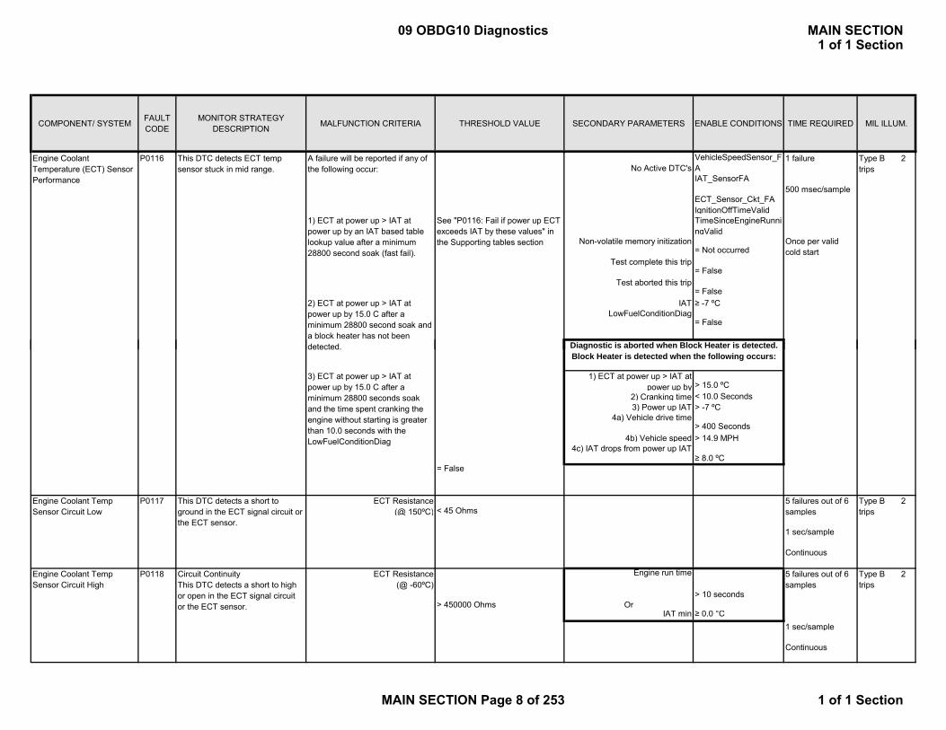
No Active DTC'sVehicleSpeedSensor_FA
1 failure
IAT_SensorFA
ECT_Sensor_Ckt_FAIgnitionOffTimeValidTimeSinceEngineRunningValid
IAT ≥ -7 ºC
500 msec/sample
This DTC detects ECT temp sensor stuck in mid range.
A failure will be reported if any of the following occur:
1) ECT at power up > IAT at power up by an IAT based table lookup value after a minimum 28800 second soak (fast fail).
See "P0116: Fail if power up ECT exceeds IAT by these values" in the Supporting tables section
= False
= Not occurred
Di ti i b t d h Bl k H t i d t t d
2) ECT at power up > IAT at power up by 15.0 C after a minimum 28800 second soak and a block heater has not been
P0116
Once per valid cold start
= False
= False
LowFuelConditionDiag
Test aborted this trip
Non-volatile memory initization
Test complete this trip
Engine Coolant Temperature (ECT) Sensor Performance
Type B 2 trips
2) Cranking time < 10.0 Seconds3) Power up IAT > -7 ºC
4b) Vehicle speed > 14.9 MPH
1 sec/sample
Continuous
Engine run time
> 10 secondsOr
IAT min ≥ 0.0 °C1 sec/sample
Continuous
5 failures out of 6 samples
ECT Resistance (@ 150ºC)
5 failures out of 6 samples
1) ECT at power up > IAT at power up by
4a) Vehicle drive time
> 15.0 ºC
Diagnostic is aborted when Block Heater is detected. Block Heater is detected when the following occurs:
> 400 Seconds
≥ 8.0 ºC
detected.
3) ECT at power up > IAT at power up by 15.0 C after a minimum 28800 seconds soak and the time spent cranking the engine without starting is greater than 10.0 seconds with the LowFuelConditionDiag
Engine Coolant Temp Sensor Circuit Low
P0117 This DTC detects a short to ground in the ECT signal circuit or the ECT sensor.
Engine Coolant Temp Sensor Circuit High
P0118 Circuit ContinuityThis DTC detects a short to high or open in the ECT signal circuit or the ECT sensor.
4c) IAT drops from power up IAT
= False
> 450000 Ohms
ECT Resistance (@ -60ºC)
< 45 OhmsType B 2 trips
Type B 2 trips
09 OBDG10 Diagnostics MAIN SECTION1 of 1 Section
MAIN SECTION Page 8 of 253 1 of 1 Section
COMPONENT/ SYSTEM FAULT CODE
MONITOR STRATEGY DESCRIPTION MALFUNCTION CRITERIA THRESHOLD VALUE SECONDARY PARAMETERS ENABLE CONDITIONS TIME REQUIRED MIL ILLUM.
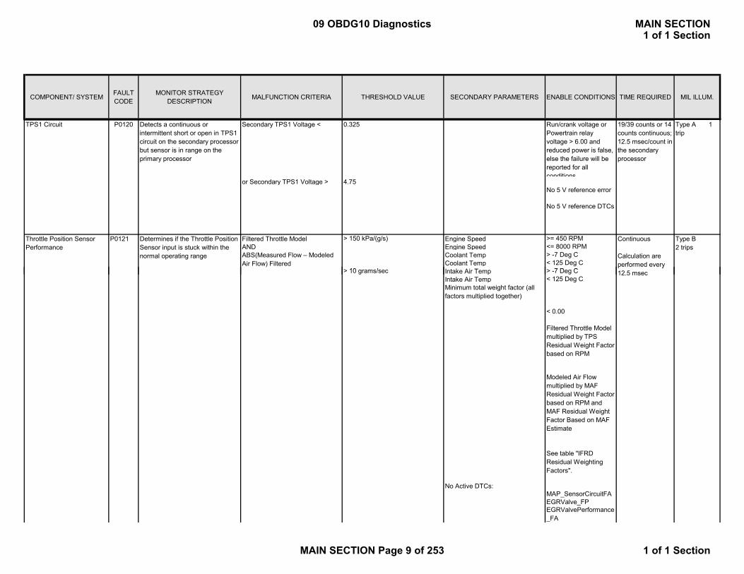
TPS1 Circuit Secondary TPS1 Voltage < 0.325 Run/crank voltage or Powertrain relay voltage > 6.00 and reduced power is false, else the failure will be reported for all conditions
or Secondary TPS1 Voltage > 4.75 No 5 V reference error
No 5 V reference DTCs
Filtered Throttle Model > 150 kPa/(g/s) Engine Speed >= 450 RPMAND Engine Speed <= 8000 RPM
Coolant Temp > -7 Deg CCoolant Temp < 125 Deg CI t k Ai T > 7 D C
P0120 19/39 counts or 14 counts continuous; 12.5 msec/count in the secondary processor
P0121 Determines if the Throttle Position Sensor input is stuck within the normal operating range ABS(Measured Flow – Modeled
Air Flow) Filtered
Continuous
Calculation are performed every
> 10 /
Detects a continuous or intermittent short or open in TPS1 circuit on the secondary processor but sensor is in range on the primary processor
Throttle Position Sensor Performance
Type A 1 trip
Type B2 trips
Intake Air Temp > -7 Deg CIntake Air Temp < 125 Deg C
No Active DTCs:MAP_SensorCircuitFAEGRValve_FPEGRValvePerformance_FA
p y12.5 msec
< 0.00
See table "IFRD Residual Weighting Factors".
Filtered Throttle Model multiplied by TPS Residual Weight Factor based on RPM
> 10 grams/sec
Minimum total weight factor (all factors multiplied together)
Modeled Air Flow multiplied by MAF Residual Weight Factor based on RPM and MAF Residual Weight Factor Based on MAF Estimate
09 OBDG10 Diagnostics MAIN SECTION1 of 1 Section
MAIN SECTION Page 9 of 253 1 of 1 Section

COMPONENT/ SYSTEM FAULT CODE
MONITOR STRATEGY DESCRIPTION MALFUNCTION CRITERIA THRESHOLD VALUE SECONDARY PARAMETERS ENABLE CONDITIONS TIME REQUIRED MIL ILLUM.
MAF_SensorCircuitFACrankSensorFAECT_sensor_FAECT_Sensor_FPIAT_SensorFAIAT_SensorCircuitFP
CylDeacSystemTFTKO
Primary TPS1 Voltage < 0.325 Run/crank voltage or Powertrain relay voltage > 6.00 and reduced power is false, else the failure will be reported for all conditions
N 5 V f
Detects a continuous or intermittent short or open in TPS1 circuit on both processors or just the primary processor
79/159 counts; 57 counts continuous; 3.125 msec /count in the Primary processor
TPS1 Circuit Low P0122 Type A 1 trip
No 5 V reference error
Secondary TPS1 Voltage < 0.325 No 5 V reference DTCs
Primary TPS1 Voltage > 4.75 Run/crank voltage or Powertrain relay voltage > 6.00 and reduced power is false, else the failure will be reported for all conditions
No 5 V reference error
Secondary TPS1 Voltage > 4.75 No 5 V reference DTCs
No Active DTC's MAP_SensorFAMAF_SensorFA
TPS_Performance_FATPS_FA 1 sec/sampleTPS_ThrottleAuthorityDefaulted
Range #1 (Primary) IAT_SensorFA
Detects a continuous or intermittent short in TPS1 circuit on both processors or just the primary processor
19/39 counts or 14 counts continuous; 12.5 msec/count in the Secondary processor
Once per ignition
Engine Coolant Temperature Below Stat Regulating Temperature
P0128
TPS1 Circuit High P0123
19/39 counts or 14 counts continuous; 12.5 msec/count in the Secondary processor
79/159 counts; 57 counts continuous; 3.125 msec /count in the Primary processor
Type B 2 trips
30 failures to set DTC
This DTC detects if the engine coolant temperature rises too slowly due to an ECT or Cooling system fault
Actual accumulated airflow is > predicted accumulated airflow before:
See “P0128: Maximum Accumulated Airflow for IAT and Start-up ECT conditions“ in the Supporting tables section
Type A 1 trip
09 OBDG10 Diagnostics MAIN SECTION1 of 1 Section
MAIN SECTION Page 10 of 253 1 of 1 Section
COMPONENT/ SYSTEM FAULT CODE
MONITOR STRATEGY DESCRIPTION MALFUNCTION CRITERIA THRESHOLD VALUE SECONDARY PARAMETERS ENABLE CONDITIONS TIME REQUIRED MIL ILLUM.
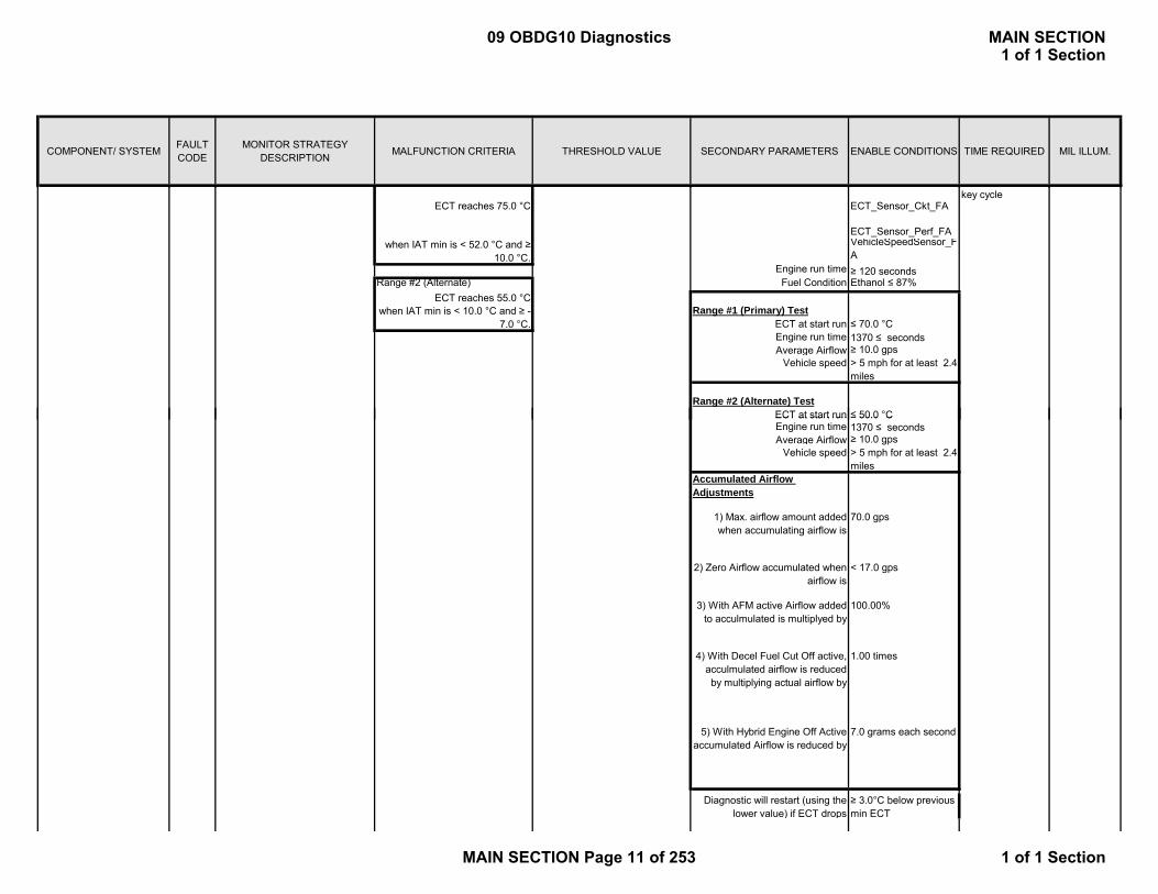
ECT reaches 75.0 °C ECT_Sensor_Ckt_FA
ECT_Sensor_Perf_FAVehicleSpeedSensor_FA
Engine run time ≥ 120 secondsRange #2 (Alternate) Fuel Condition Ethanol ≤ 87%
ECT reaches 55.0 °C
ECT at start run ≤ 70.0 °CEngine run time 1370 ≤ secondsAverage Airflow ≥ 10.0 gps
Vehicle speed > 5 mph for at least 2.4 miles
ECT at start run ≤ 50.0 °C
key cycle
when IAT min is < 52.0 °C and ≥ 10.0 °C.
when IAT min is < 10.0 °C and ≥ -7.0 °C.
Range #2 (Alternate) Test
Range #1 (Primary) Test
ECT at start run ≤ 50.0 CEngine run time 1370 ≤ secondsAverage Airflow ≥ 10.0 gps
Vehicle speed > 5 mph for at least 2.4 miles
7.0 grams each second
Diagnostic will restart (using the lower value) if ECT drops
Accumulated Airflow Adjustments
1) Max. airflow amount added when accumulating airflow is
70.0 gps
2) Zero Airflow accumulated when airflow is
< 17.0 gps
5) With Hybrid Engine Off Active accumulated Airflow is reduced by
3) With AFM active Airflow added to acculmulated is multiplyed by
4) With Decel Fuel Cut Off active, acculmulated airflow is reduced by multiplying actual airflow by
≥ 3.0°C below previous min ECT
100.00%
1.00 times
09 OBDG10 Diagnostics MAIN SECTION1 of 1 Section
MAIN SECTION Page 11 of 253 1 of 1 Section
COMPONENT/ SYSTEM FAULT CODE
MONITOR STRATEGY DESCRIPTION MALFUNCTION CRITERIA THRESHOLD VALUE SECONDARY PARAMETERS ENABLE CONDITIONS TIME REQUIRED MIL ILLUM.
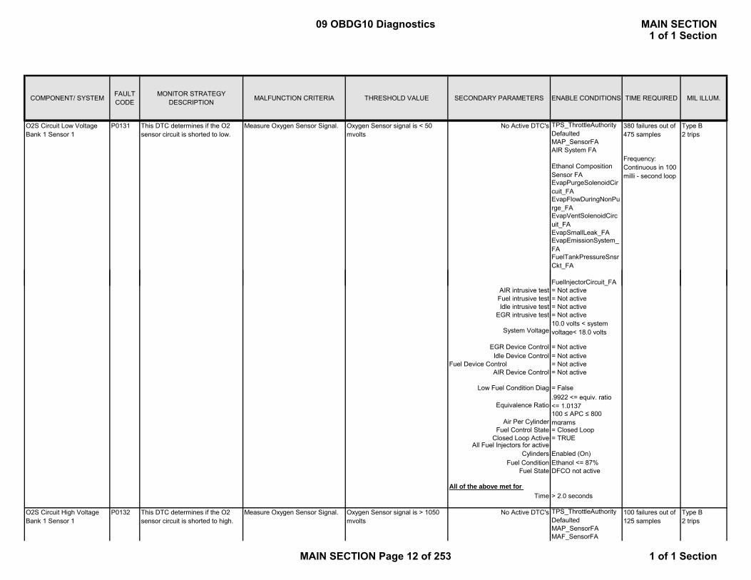
No Active DTC's TPS_ThrottleAuthorityDefaultedMAP_SensorFAAIR System FA
Ethanol Composition Sensor FAEvapPurgeSolenoidCircuit_FAEvapFlowDuringNonPurge_FAEvapVentSolenoidCircuit_FAEvapSmallLeak_FAEvapEmissionSystem_FAFuelTankPressureSnsrCkt_FA
380 failures out of 475 samples
Type B2 trips
Frequency: Continuous in 100 milli - second loop
O2S Circuit Low Voltage Bank 1 Sensor 1
This DTC determines if the O2 sensor circuit is shorted to low.
P0131 Measure Oxygen Sensor Signal. Oxygen Sensor signal is < 50 mvolts
FuelInjectorCircuit_FAAIR intrusive test = Not activeFuel intrusive test = Not activeIdle intrusive test = Not active
EGR intrusive test = Not active
Idle Device Control = Not activeFuel Device Control = Not active
AIR Device Control = Not active
Equivalence Ratio.9922 <= equiv. ratio <= 1.0137
Air Per Cylinder100 ≤ APC ≤ 800 mgrams
Fuel Control State = Closed LoopClosed Loop Active = TRUE
Fuel Condition Ethanol <= 87%Fuel State DFCO not active
Time > 2.0 seconds
No Active DTC's TPS_ThrottleAuthorityDefaultedMAP_SensorFAMAF_SensorFA
10.0 volts < system voltage< 18.0 volts
Enabled (On)
100 failures out of 125 samples
Type B2 trips
P0132O2S Circuit High Voltage Bank 1 Sensor 1
This DTC determines if the O2 sensor circuit is shorted to high.
Measure Oxygen Sensor Signal.
= Not active
Low Fuel Condition Diag = False
System Voltage
Oxygen Sensor signal is > 1050 mvolts
All of the above met for
EGR Device Control
All Fuel Injectors for active Cylinders
09 OBDG10 Diagnostics MAIN SECTION1 of 1 Section
MAIN SECTION Page 12 of 253 1 of 1 Section
COMPONENT/ SYSTEM FAULT CODE
MONITOR STRATEGY DESCRIPTION MALFUNCTION CRITERIA THRESHOLD VALUE SECONDARY PARAMETERS ENABLE CONDITIONS TIME REQUIRED MIL ILLUM.
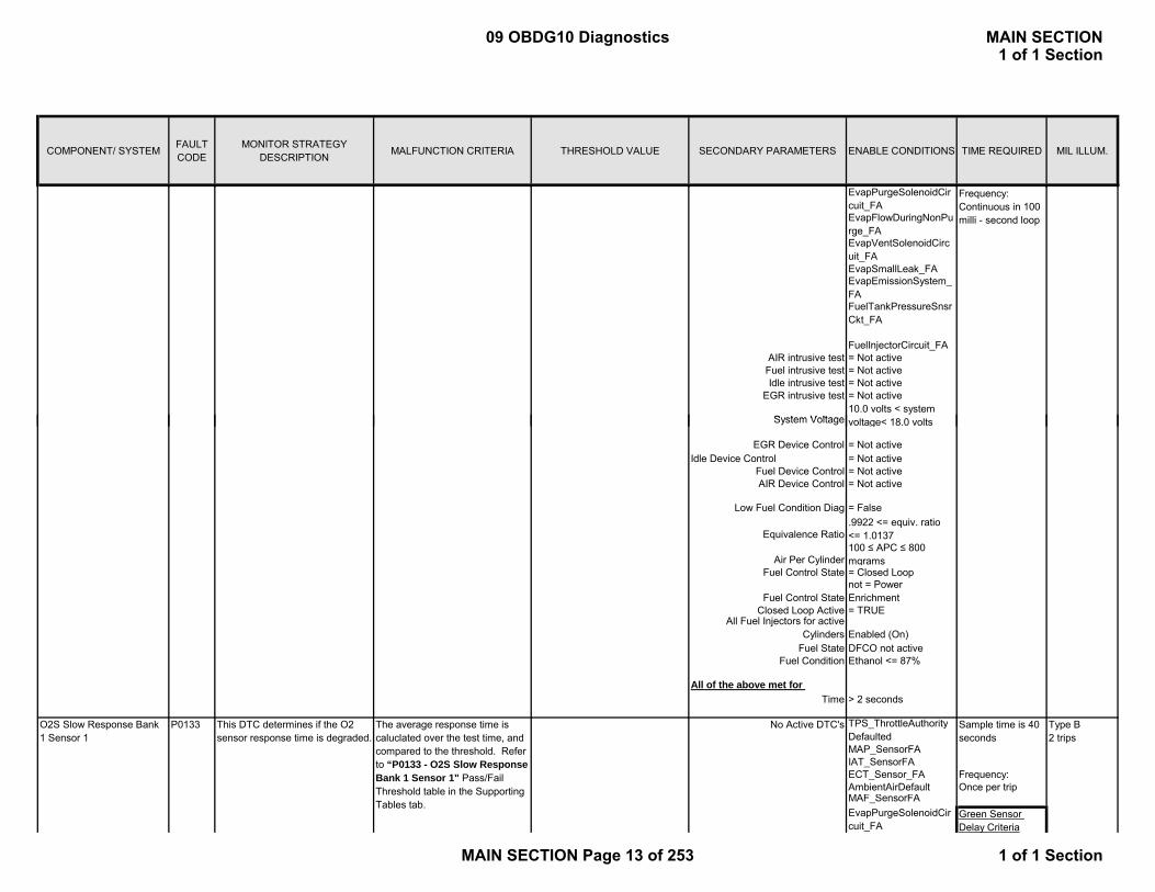
EvapPurgeSolenoidCircuit_FAEvapFlowDuringNonPurge_FAEvapVentSolenoidCircuit_FAEvapSmallLeak_FAEvapEmissionSystem_FAFuelTankPressureSnsrCkt_FA
FuelInjectorCircuit_FAAIR intrusive test = Not activeFuel intrusive test = Not activeIdle intrusive test = Not active
EGR intrusive test = Not active10.0 volts < system
lt 18 0 lt
Frequency: Continuous in 100 milli - second loop
System Voltage
Idle Device Control = Not activeFuel Device Control = Not activeAIR Device Control = Not active
Equivalence Ratio.9922 <= equiv. ratio <= 1.0137
Air Per Cylinder100 ≤ APC ≤ 800 mgrams
Fuel Control State = Closed Loop
Fuel Control Statenot = Power Enrichment
Closed Loop Active = TRUE
Fuel State DFCO not activeFuel Condition Ethanol <= 87%
Time > 2 seconds
No Active DTC's TPS_ThrottleAuthorityDefaultedMAP_SensorFAIAT_SensorFAECT_Sensor_FA Frequency: AmbientAirDefault Once per tripMAF_SensorFAEvapPurgeSolenoidCircuit_FA
voltage< 18.0 volts
= False
Sample time is 40 seconds
Green Sensor Delay Criteria
= Not active
Enabled (On)
Type B2 trips
O2S Slow Response Bank 1 Sensor 1
P0133 This DTC determines if the O2 sensor response time is degraded.
All of the above met for
Low Fuel Condition Diag
The average response time is caluclated over the test time, and compared to the threshold. Refer to “P0133 - O2S Slow Response Bank 1 Sensor 1" Pass/Fail Threshold table in the Supporting Tables tab.
EGR Device Control
System Voltage
All Fuel Injectors for active Cylinders
09 OBDG10 Diagnostics MAIN SECTION1 of 1 Section
MAIN SECTION Page 13 of 253 1 of 1 Section

COMPONENT/ SYSTEM FAULT CODE
MONITOR STRATEGY DESCRIPTION MALFUNCTION CRITERIA THRESHOLD VALUE SECONDARY PARAMETERS ENABLE CONDITIONS TIME REQUIRED MIL ILLUM.
EvapFlowDuringNonPurge_FAEvapVentSolenoidCircuit_FAEvapSmallLeak_FAEvapEmissionSystem_FAFuelTankPressureSnsrCkt_FA
FuelInjectorCircuit_FAAIR System FAEthanolCompositionSensor_FAEngineMisfireDetected_FA
The diagnostic will not be enabled until the next ignition cycle after the following has been met: Airflow greater than 22 gps for 120000 grams of accumulated flow non-continuously. (Note that all other enable criteria must be met on the next ignition cycle for the test to10 0 lt t
= P0131, P0132 or P0134Bank 1 Sensor 1 DTC's not active
Idle Device Control = Not activeFuel Device Control = Not activeAIR Device Control = Not active
O2 Heater on for >= 0 seconds
Engine Coolant > 55 ºCIAT > -40 ºC
Engine run Accum > 160 secondsPurge duty cycle >= 0 % duty cycle
Engine speed 1000 <= RPM <= 3000Fuel < 87 % EthanolBaro > 70 kpa
Air Per Cylinder >= 150 mGrams
Fuel Control State = Closed LoopClosed Loop Active = TRUE
LTM fuel cell = Enabled
Baro = Not Defaulted
cycle for the test to run on that ignition cycle).Note: This feature is only enabled when the vehicle is new and cannot be enabled in service
10.0 volts < system voltage< 18.0 volts
= Not Valid
<= 100.0 mgrams
20 gps <= engine airflow <= 55 gps
Low Fuel Condition Diag
Engine airflow
EGR Device Control = Not active
= False
Learned Htr resistance = Valid
Transient Fuel Mass
Green O2S Condition
System Voltage
Low Fuel Condition Diag = False
09 OBDG10 Diagnostics MAIN SECTION1 of 1 Section
MAIN SECTION Page 14 of 253 1 of 1 Section
COMPONENT/ SYSTEM FAULT CODE
MONITOR STRATEGY DESCRIPTION MALFUNCTION CRITERIA THRESHOLD VALUE SECONDARY PARAMETERS ENABLE CONDITIONS TIME REQUIRED MIL ILLUM.
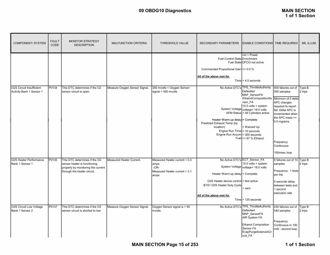
Fuel Control Statenot = Power Enrichment
Fuel State DFCO not active
Time > 4.5 seconds
No Active DTC's TPS_ThrottleAuthorityDefaultedMAF_SensorFAEthanolCompositionSensor_FA
AFM Status = All Cylinders active
O2S Circuit Insufficient Activity Bank 1 Sensor 1
Minimum of 0 delta APC changes required to report fail. Delta APC is incremented when the APC mass >=
>= 0.0 %
Type B2 trips
400 failures out of 500 samples.
P0134 350 mvolts < Oxygen Sensor signal < 550 mvolts
Heater Warm up delay
This DTC determines if the O2 sensor circuit is open.
Measure Oxygen Sensor Signal.
Commanded Proportional Gain
All of the above met for
10.0 volts < system voltage< 18.0 voltsSystem Voltage
= Complete
Engine Run Time > 10 secondsEngine Run Accum > 300 seconds
Fuel <= 87 % Ethanol
100msec loop
No Active DTC's ECT_Sensor_FA
Time > 120 seconds
No Active DTC's TPS_ThrottleAuthorityDefaultedMAP_SensorFAAIR System FA
Ethanol Composition Sensor FAEvapPurgeSolenoidCircuit_FA
This DTC determines if the O2 sensor circuit is shorted to low.
Frequency: Continuous
Frequency: 1 tests per trip
5 seconds delay between tests and 1 second execution rate
This DTC determines if the O2 sensor heater is functioning properly by monitoring the current through the heater circuit.
> zero
0.0 mgrams
8 failures out of 10 samples
O2S Circuit Low Voltage Bank 1 Sensor 2
P0137
O2S Heater Performance Bank 1 Sensor 1
= Complete
O2S Heater device control = Not active
Heater Warm-up delay
Heater Warm-up delayPredicted Exhaust Temp (by
location)
Measured Heater current < 0.3 amps -OR- Measured Heater current > 3.1 amps
All of the above met for
10.0 volts < system voltage< 18.0 volts
= Wamed Up
= Complete
System Voltage
P0135 Type B2 trips
Measure Oxygen Sensor Signal. Oxygen Sensor signal is < 50 mvolts
430 failures out of 540 samples
Type B2 trips
Frequency: Continuous in 100 milli - second loop
Measured Heater Current.
B1S1 O2S Heater Duty Cycle
09 OBDG10 Diagnostics MAIN SECTION1 of 1 Section
MAIN SECTION Page 15 of 253 1 of 1 Section
COMPONENT/ SYSTEM FAULT CODE
MONITOR STRATEGY DESCRIPTION MALFUNCTION CRITERIA THRESHOLD VALUE SECONDARY PARAMETERS ENABLE CONDITIONS TIME REQUIRED MIL ILLUM.
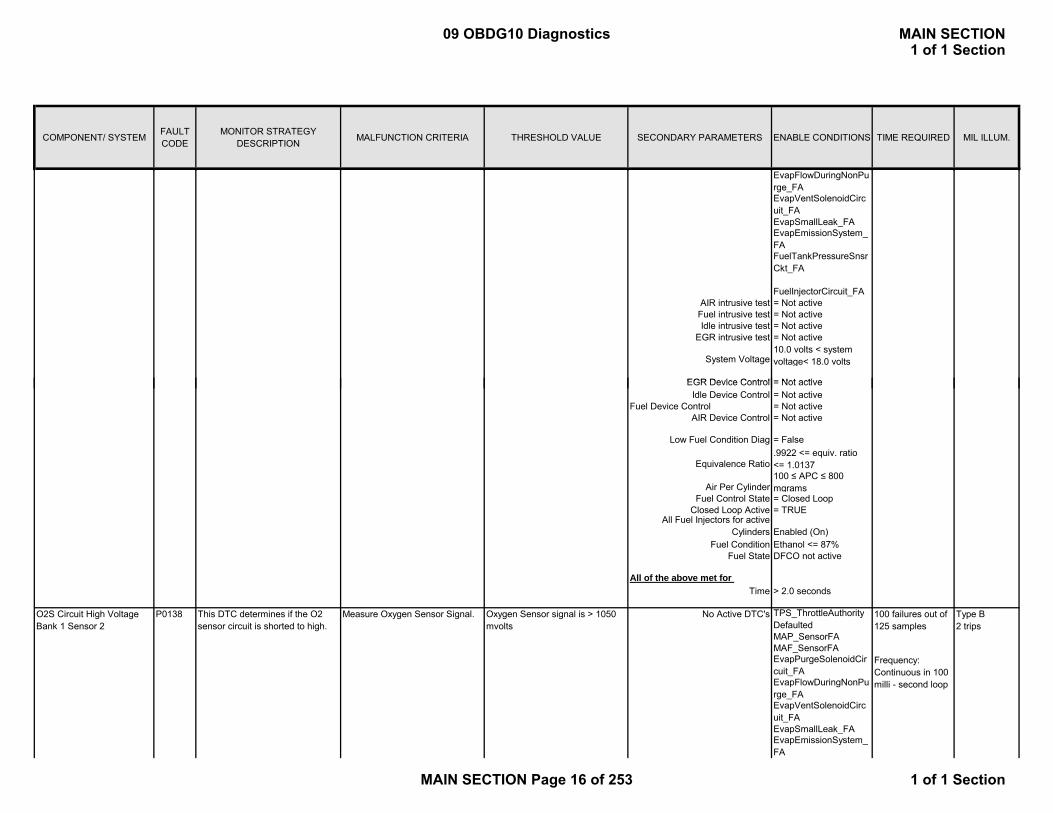
EvapFlowDuringNonPurge_FAEvapVentSolenoidCircuit_FAEvapSmallLeak_FAEvapEmissionSystem_FAFuelTankPressureSnsrCkt_FA
FuelInjectorCircuit_FAAIR intrusive test = Not activeFuel intrusive test = Not activeIdle intrusive test = Not active
EGR intrusive test = Not active
= Not active
System Voltage10.0 volts < system voltage< 18.0 volts
EGR Device ControlIdle Device Control = Not active
Fuel Device Control = Not activeAIR Device Control = Not active
Equivalence Ratio.9922 <= equiv. ratio <= 1.0137
Air Per Cylinder100 ≤ APC ≤ 800 mgrams
Fuel Control State = Closed LoopClosed Loop Active = TRUE
Fuel Condition Ethanol <= 87%Fuel State DFCO not active
Time > 2.0 seconds
No Active DTC's TPS_ThrottleAuthorityDefaultedMAP_SensorFAMAF_SensorFAEvapPurgeSolenoidCircuit_FAEvapFlowDuringNonPurge_FAEvapVentSolenoidCircuit_FAEvapSmallLeak_FAEvapEmissionSystem_FA
Measure Oxygen Sensor Signal. 100 failures out of 125 samples
Type B2 trips
Frequency: Continuous in 100 milli - second loop
O2S Circuit High Voltage Bank 1 Sensor 2
P0138 This DTC determines if the O2 sensor circuit is shorted to high.
Oxygen Sensor signal is > 1050 mvolts
All Fuel Injectors for active Cylinders Enabled (On)
= Not active
Low Fuel Condition Diag
EGR Device Control
= False
All of the above met for
09 OBDG10 Diagnostics MAIN SECTION1 of 1 Section
MAIN SECTION Page 16 of 253 1 of 1 Section

COMPONENT/ SYSTEM FAULT CODE
MONITOR STRATEGY DESCRIPTION MALFUNCTION CRITERIA THRESHOLD VALUE SECONDARY PARAMETERS ENABLE CONDITIONS TIME REQUIRED MIL ILLUM.
FuelTankPressureSnsrCkt_FA
FuelInjectorCircuit_FAAIR intrusive test = Not activeFuel intrusive test = Not activeIdle intrusive test = Not active
EGR intrusive test = Not active
Idle Device Control = Not activeFuel Device Control = Not activeAIR Device Control = Not active
Equivalence Ratio.9922 <= equiv. ratio
1 0137
= False
EGR Device Control = Not active
10.0 volts < system voltage< 18.0 voltsSystem Voltage
Low Fuel Condition Diag
Equivalence Ratio <= 1.0137
Air Per Cylinder100 ≤ APC ≤ 800 mgrams
Fuel Control State = Closed Loop
Fuel Control Statenot = Power Enrichment
Closed Loop Active = TRUE
Fuel State DFCO not activeFuel Condition Ethanol <= 87%
Time > 2 seconds
No Active DTC's TPS_ThrottleAuthorityDefaultedMAF_SensorFAEthanolCompositionSensor_FA
AFM Status = All Cylinders active
Engine Run Time > 10 secondsEngine Run Accum > 300 seconds
Fuel <= 87 % Ethanol
590 failures out of 740 samples.
10.0 volts < system voltage< 18.0 volts
Type B2 trips
Minimum of 0 delta APC changes required to report fail. Delta APC is incremented when the APC mass >= 0.0 mgrams
Frequency: Once per trip for post sensors
O2S Circuit Insufficient Activity Bank 1 Sensor 2
Measure Oxygen Sensor Signal. 410 mvolts < Oxygen Sensor signal < 490 mvolts
= CompleteHeater Warm-up delay
System Voltage
This DTC determines if the O2 sensor circuit is open.
P0140
Enabled (On)
All of the above met for
Predicted Exhaust Temp (by location) = Wamed Up
All Fuel Injectors for active Cylinders
09 OBDG10 Diagnostics MAIN SECTION1 of 1 Section
MAIN SECTION Page 17 of 253 1 of 1 Section

COMPONENT/ SYSTEM FAULT CODE
MONITOR STRATEGY DESCRIPTION MALFUNCTION CRITERIA THRESHOLD VALUE SECONDARY PARAMETERS ENABLE CONDITIONS TIME REQUIRED MIL ILLUM.
100msec loop
No Active DTC's ECT_Sensor_FA
Time > 120 seconds
No Active DTC's TPS_ThrottleAuthorityDefaulted
10.0 volts < system voltage< 18.0 volts
= Not active
Frequency: 1 tests per trip
8 failures out of 10 samples
Measure Oxygen Sensor Signal.O2S Circuit Low Voltage B k 2 S 1
> zero
= Complete
Oxygen Sensor signal is < 50 lt
Measured Heater current < 0.3 amps -OR- Measured Heater current > 2.9 amps
This DTC determines if the O2 i it i h t d t l
P0151
All of the above met for
System Voltage
B1S1 O2S Heater Duty Cycle
Heater Warm-up delay
380 failures out of 475 l
5 seconds delay between tests and 1 second execution rate
Type B2 t i
Type B2 trips
This DTC determines if the O2 sensor heater is functioning properly by monitoring the current through the heater circuit.
Measured Heater Current.O2S Heater Performance Bank 1 Sensor 2
O2S Heater device control
P0141
DefaultedMAP_SensorFAAIR System FA
Ethanol Composition Sensor FAEvapPurgeSolenoidCircuit_FAEvapFlowDuringNonPurge_FAEvapVentSolenoidCircuit_FAEvapSmallLeak_FAEvapEmissionSystem_FAFuelTankPressureSnsrCkt_FA
FuelInjectorCircuit_FAAIR intrusive test = Not activeFuel intrusive test = Not activeIdle intrusive test = Not active
EGR intrusive test = Not active
Idle Device Control = Not activeFuel Device Control = Not active
AIR Device Control = Not active
Bank 2 Sensor 1 mvoltssensor circuit is shorted to low.
EGR Device Control
System Voltage
= False
= Not active
10.0 volts < system voltage< 18.0 volts
475 samples
Frequency: Continuous in 100 milli - second loop
2 trips
Low Fuel Condition Diag
09 OBDG10 Diagnostics MAIN SECTION1 of 1 Section
MAIN SECTION Page 18 of 253 1 of 1 Section

COMPONENT/ SYSTEM FAULT CODE
MONITOR STRATEGY DESCRIPTION MALFUNCTION CRITERIA THRESHOLD VALUE SECONDARY PARAMETERS ENABLE CONDITIONS TIME REQUIRED MIL ILLUM.
Equivalence Ratio.9922 <= equiv. ratio <= 1.0137
Air Per Cylinder100 ≤ APC ≤ 800 mgrams
Fuel Control State = Closed LoopClosed Loop Active = TRUE
Fuel Condition Ethanol <= 87%Fuel State DFCO not active
Time > 2.0 seconds
No Active DTC's TPS_ThrottleAuthorityDefaultedMAP_SensorFAMAF_SensorFAEvapPurgeSolenoidCir
Oxygen Sensor signal is > 1050 mvolts
Measure Oxygen Sensor Signal.
All of the above met for
O2S Circuit High Voltage Bank 2 Sensor 1
This DTC determines if the O2 sensor circuit is shorted to high.
P0152
All Fuel Injectors for active Cylinders Enabled (On)
100 failures out of 125 samples
F
Type B2 trips
EvapPurgeSolenoidCircuit_FAEvapFlowDuringNonPurge_FAEvapVentSolenoidCircuit_FAEvapSmallLeak_FAEvapEmissionSystem_FAFuelTankPressureSnsrCkt_FA
FuelInjectorCircuit_FAAIR intrusive test = Not activeFuel intrusive test = Not activeIdle intrusive test = Not active
EGR intrusive test = Not active
Idle Device Control = Not activeFuel Device Control = Not activeAIR Device Control = Not active
Equivalence Ratio.9922 <= equiv. ratio <= 1.0137
Air Per Cylinder100 ≤ APC ≤ 800 mgrams
Fuel Control State = Closed Loop
Fuel Control Statenot = Power Enrichment
EGR Device Control
= False
= Not active
System Voltage10.0 volts < system voltage< 18.0 volts
Low Fuel Condition Diag
Frequency: Continuous in 100 milli - second loop
09 OBDG10 Diagnostics MAIN SECTION1 of 1 Section
MAIN SECTION Page 19 of 253 1 of 1 Section
COMPONENT/ SYSTEM FAULT CODE
MONITOR STRATEGY DESCRIPTION MALFUNCTION CRITERIA THRESHOLD VALUE SECONDARY PARAMETERS ENABLE CONDITIONS TIME REQUIRED MIL ILLUM.
Closed Loop Active = TRUE
Fuel State DFCO not activeFuel Condition Ethanol <= 87%
Time > 2 seconds
No Active DTC's TPS_ThrottleAuthorityDefaultedMAP_SensorFAIAT_SensorFAECT_Sensor_FA Frequency: AmbientAirDefault Once per tripMAF_SensorFAEvapPurgeSolenoidCircuit_FAEvapFlowDuringNonPu
Sample time is 40 seconds
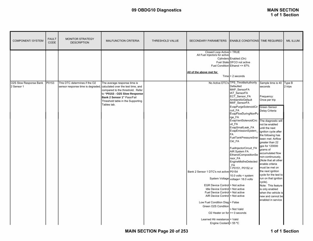
P0153 This DTC determines if the O2 sensor response time is degraded.
The average response time is caluclated over the test time, and compared to the threshold. Refer to “P0153 - O2S Slow Response Bank 2 Sensor 1" Pass/Fail Threshold table in the Supporting Tables tab.
O2S Slow Response Bank 2 Sensor 1
Enabled (On)All Fuel Injectors for active
Cylinders
Type B2 trips
Green Sensor Delay Criteria
All of the above met for
EvapFlowDuringNonPurge_FAEvapVentSolenoidCircuit_FAEvapSmallLeak_FAEvapEmissionSystem_FAFuelTankPressureSnsrCkt_FA
FuelInjectorCircuit_FAAIR System FAEthanolCompositionSensor_FAEngineMisfireDetected_FA
Idle Device Control = Not activeFuel Device Control = Not activeAIR Device Control = Not active
O2 Heater on for >= 0 seconds
Engine Coolant > 55 ºC
= P0151, P0152 or P0154Bank 2 Sensor 1 DTC's not active
Low Fuel Condition DiagGreen O2S Condition
System Voltage
EGR Device Control
Learned Htr resistance
= False
= Not Valid
= Valid
= Not active
10.0 volts < system voltage< 18.0 volts
The diagnostic will not be enabled until the next ignition cycle after the following has been met: Airflow greater than 22 gps for 120000 grams of accumulated flow non-continuously. (Note that all other enable criteria must be met on the next ignition cycle for the test to run on that ignition cycle).Note: This feature is only enabled when the vehicle is new and cannot be enabled in service
09 OBDG10 Diagnostics MAIN SECTION1 of 1 Section
MAIN SECTION Page 20 of 253 1 of 1 Section

COMPONENT/ SYSTEM FAULT CODE
MONITOR STRATEGY DESCRIPTION MALFUNCTION CRITERIA THRESHOLD VALUE SECONDARY PARAMETERS ENABLE CONDITIONS TIME REQUIRED MIL ILLUM.
IAT > -40 ºCEngine run Accum > 160 seconds
Purge duty cycle >= 0 % duty cycle
Engine speed 1000 <= RPM <= 3000Fuel < 87 % EthanolBaro > 70 kpa
Air Per Cylinder >= 150 mGrams
Fuel Control State = Closed LoopClosed Loop Active = TRUE
LTM fuel cell = Enabled
Baro = Not Defaultednot = Power
Low Fuel Condition Diag = False
<= 100.0 mgrams
Engine airflow
Transient Fuel Mass
20 gps <= engine airflow <= 55 gps
Fuel Control Statenot = Power Enrichment
Fuel State DFCO not active
Time > 4.5 seconds
No Active DTC's TPS_ThrottleAuthorityDefaultedMAF_SensorFAEthanolCompositionSensor_FA
AFM Status = All Cylinders active
Engine Run Time > 10 secondsEngine Run Accum > 300 seconds
Fuel <= 87 % Ethanol
100msec loop
No Active DTC's ECT_Sensor_FA
350 mvolts < Oxygen Sensor signal < 550 mvolts
Measured Heater Current.10.0 volts < system voltage< 18.0 voltsSystem Voltage
This DTC determines if the O2 sensor circuit is open.
Measure Oxygen Sensor Signal.
This DTC determines if the O2 sensor heater is functioning properly by monitoring the current through the heater circuit.
Heater Warm-up delayPredicted Exhaust Temp (by
location)
O2S Heater Performance Bank 2 Sensor 1
P0155
O2S Circuit Insufficient Activity Bank 2 Sensor 1
P0154
All of the above met for
System Voltage
>= 0.0 %Commanded Proportional Gain
8 failures out of 10 samples
Type B2 trips
Frequency: 1 tests
Type B2 trips
Minimum of 0 delta APC changes required to report fail. Delta APC is incremented when the APC mass >= 0.0 mgrams
10.0 volts < system voltage< 18.0 volts
= Complete
= Wamed Up
Frequency: Continuous
400 failures out of 500 samples.
Measured Heater current < 0.3 amps -OR- Measured Heater current > 3.1
09 OBDG10 Diagnostics MAIN SECTION1 of 1 Section
MAIN SECTION Page 21 of 253 1 of 1 Section
COMPONENT/ SYSTEM FAULT CODE
MONITOR STRATEGY DESCRIPTION MALFUNCTION CRITERIA THRESHOLD VALUE SECONDARY PARAMETERS ENABLE CONDITIONS TIME REQUIRED MIL ILLUM.
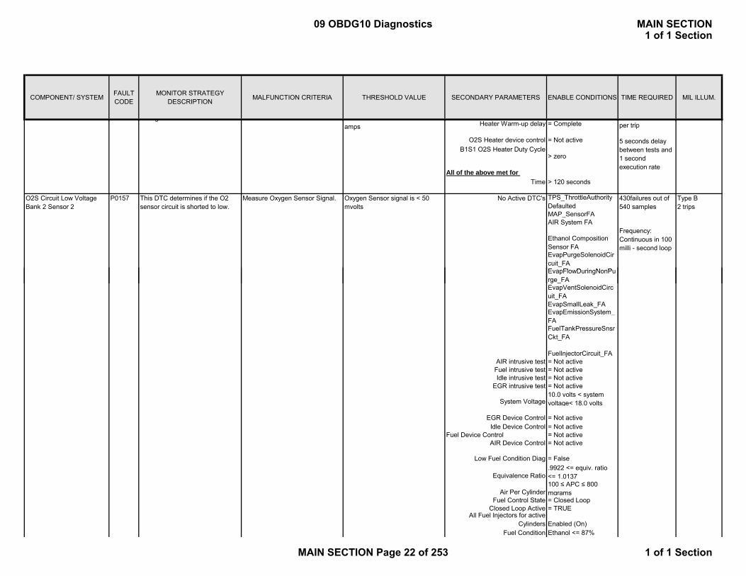
Time > 120 seconds
No Active DTC's TPS_ThrottleAuthorityDefaultedMAP_SensorFAAIR System FA
Ethanol Composition Sensor FAEvapPurgeSolenoidCircuit_FAEvapFlowDuringNonPu
All of the above met for
O2S Heater device control
> zero
g= Complete
O2S Circuit Low Voltage Bank 2 Sensor 2
= Not active
per trip
Type B2 trips
Heater Warm-up delay
5 seconds delay between tests and 1 second execution rate
amps
P0157 This DTC determines if the O2 sensor circuit is shorted to low.
Measure Oxygen Sensor Signal. Oxygen Sensor signal is < 50 mvolts
Frequency: Continuous in 100 milli - second loop
430failures out of 540 samples
B1S1 O2S Heater Duty Cycle
EvapFlowDuringNonPurge_FAEvapVentSolenoidCircuit_FAEvapSmallLeak_FAEvapEmissionSystem_FAFuelTankPressureSnsrCkt_FA
FuelInjectorCircuit_FAAIR intrusive test = Not activeFuel intrusive test = Not activeIdle intrusive test = Not active
EGR intrusive test = Not active
Idle Device Control = Not activeFuel Device Control = Not active
AIR Device Control = Not active
Equivalence Ratio.9922 <= equiv. ratio <= 1.0137
Air Per Cylinder100 ≤ APC ≤ 800 mgrams
Fuel Control State = Closed LoopClosed Loop Active = TRUE
Fuel Condition Ethanol <= 87%
Low Fuel Condition Diag
System Voltage
EGR Device Control
Enabled (On)All Fuel Injectors for active
Cylinders
= Not active
= False
10.0 volts < system voltage< 18.0 volts
09 OBDG10 Diagnostics MAIN SECTION1 of 1 Section
MAIN SECTION Page 22 of 253 1 of 1 Section

COMPONENT/ SYSTEM FAULT CODE
MONITOR STRATEGY DESCRIPTION MALFUNCTION CRITERIA THRESHOLD VALUE SECONDARY PARAMETERS ENABLE CONDITIONS TIME REQUIRED MIL ILLUM.
Fuel State DFCO not active
Time > 2.0 seconds
No Active DTC's TPS_ThrottleAuthorityDefaultedMAP_SensorFAMAF_SensorFAEvapPurgeSolenoidCircuit_FAEvapFlowDuringNonPurge_FAEvapVentSolenoidCircuit_FAEvapSmallLeak_FAEvapEmissionSystem_FAFuelTankPressureSnsr
O2S Circuit High Voltage Bank 2 Sensor 2
P0158 This DTC determines if the O2 sensor circuit is shorted to high.
Oxygen Sensor signal is > 1050 mvolts
Measure Oxygen Sensor Signal.
All of the above met for
Type B2 trips
Frequency: Continuous in 100 milli - second loop
100 failures out of 125 samples
FuelTankPressureSnsrCkt_FA
FuelInjectorCircuit_FAAIR intrusive test = Not activeFuel intrusive test = Not activeIdle intrusive test = Not active
EGR intrusive test = Not active
Idle Device Control = Not activeFuel Device Control = Not activeAIR Device Control = Not active
Equivalence Ratio.9922 <= equiv. ratio <= 1.0137
Air Per Cylinder100 ≤ APC ≤ 800 mgrams
Fuel Control State = Closed Loop
Fuel Control Statenot = Power Enrichment
Closed Loop Active = TRUE
Fuel State DFCO not activeFuel Condition Ethanol <= 87%
Time > 2 secondsAll of the above met for
EGR Device Control = Not active
System Voltage10.0 volts < system voltage< 18.0 volts
Low Fuel Condition Diag = False
All Fuel Injectors for active Cylinders Enabled (On)
09 OBDG10 Diagnostics MAIN SECTION1 of 1 Section
MAIN SECTION Page 23 of 253 1 of 1 Section
COMPONENT/ SYSTEM FAULT CODE
MONITOR STRATEGY DESCRIPTION MALFUNCTION CRITERIA THRESHOLD VALUE SECONDARY PARAMETERS ENABLE CONDITIONS TIME REQUIRED MIL ILLUM.
No Active DTC's TPS_ThrottleAuthorityDefaultedMAF_SensorFAEthanolCompositionSensor_FA
AFM Status = All Cylinders active
Engine Run Time > 10 secondsEngine Run Accum > 300 seconds
Fuel <= 87 % Ethanol
= Complete
System Voltage10.0 volts < system voltage< 18.0 volts
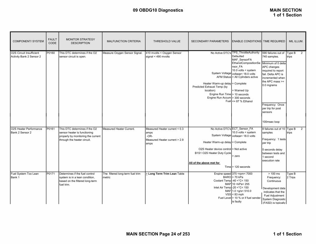
O2S Circuit Insufficient Activity Bank 2 Sensor 2
P0160 Measure Oxygen Sensor Signal. 410 mvolts < Oxygen Sensor signal < 490 mvolts
Predicted Exhaust Temp (by location) = Wamed Up
This DTC determines if the O2 sensor circuit is open.
Heater Warm-up delay
590 failures out of 740 samples.
Type B 2 trips
Frequency: Once per trip for post sensors
Minimum of 0 delta APC changes required to report fail. Delta APC is incremented when the APC mass >= 0.0 mgrams
100msec loop
No Active DTC's ECT_Sensor_FA
Time > 120 seconds
Engine speed 375 <rpm< 7000BARO > 70 kPa
Coolant Temp -40 <°C< 150MAP 10 <kPa< 255
Inlet Air Temp -20 <°C< 150MAF 1.0 <g/s< 510.0VSS < 83 mph
Fuel Level > 10 % or if fuel sender is faulty
O2S Heater Performance Bank 2 Sensor 2
P0161
Fuel System Too Lean Bank 1
The filtered long-term fuel trim metric
> Long Term Trim Lean Table > 100 msFrequency: Continuous
Development data indicates that the Fuel Adjustment
System Diagnostic (FASD) is typically
P0171 Determines if the fuel control system is in a lean condition, based on the filtered long-term fuel trim.
This DTC determines if the O2 sensor heater is functioning properly by monitoring the current through the heater circuit.
O2S Heater device control
Type B2 Trips
Frequency: 1 tests per trip
Type B 2 trips
Heater Warm-up delay
Measured Heater current < 0.3 amps -OR- Measured Heater current > 2.9 amps
8 failures out of 10 samples
System Voltage10.0 volts < system voltage< 18.0 volts
= Not active 5 seconds delay between tests and 1 second execution rate
B1S1 O2S Heater Duty Cycle> zero
All of the above met for
= Complete
Measured Heater Current.
09 OBDG10 Diagnostics MAIN SECTION1 of 1 Section
MAIN SECTION Page 24 of 253 1 of 1 Section

COMPONENT/ SYSTEM FAULT CODE
MONITOR STRATEGY DESCRIPTION MALFUNCTION CRITERIA THRESHOLD VALUE SECONDARY PARAMETERS ENABLE CONDITIONS TIME REQUIRED MIL ILLUM.
Long Fuel Trim data accumulation:
> 30 seconds of data must accumulate on each trip, with at least 10 seconds of data in the current fuel trim cell before a pass or fail decision can be made.
Long Fuel Trim enabled Closed Loop Enabled and coolant temp > 39 and < 140
disable Engine speed rpm< 375 or rpm> 7000
conditions: Fuel Level < 10 % for at least 30 seconds
Closed loop fueling Enabled
EGR Flow Diag. Intrusive Test Active
( ) yp yenabled during
95% of the EPAIII drive cycle while
the engine is being fueled. This is also
typical of real-world driving,
however values will vary (higher or lower) based on
the actual conditions present
during the drive cycle.
No active DTCs: IAC_SystemRPM_FA
MAP_SensorFAMAF_SensorFAMAF_SensorTFTKOAIR System FAEvapPurgeSolenoidCircuit FAEvapFlowDuringNonPurge FAEvapVentSolenoidCircuit FAEvapSmallLeak_FAEvapEmissionSystem_FAFuelTankPressureSensorCircuit FAEthanol Composition Sensor FA
FuelInjectorCircuit_FA
EngineMisfireDetectedFA
EGRValvePerformanceFA
EGRValveCircuit_FA
EVAP Diag. “tank pull down” portion of the test ActiveDevice Control Active
Post O2 Diag. Intrusive Test Active
fuel trim metric updated during decels? (NO)
G o ag t us e est ct eCatalyst Monitor Diag. Intrusive Test Active
09 OBDG10 Diagnostics MAIN SECTION1 of 1 Section
MAIN SECTION Page 25 of 253 1 of 1 Section

COMPONENT/ SYSTEM FAULT CODE
MONITOR STRATEGY DESCRIPTION MALFUNCTION CRITERIA THRESHOLD VALUE SECONDARY PARAMETERS ENABLE CONDITIONS TIME REQUIRED MIL ILLUM.
MAP_EngineVacuumStatusAmbientAirDefault_NA
BARO > 70 kPaCoolant Temp -40 <°C< 150
MAP 10 <kPa< 255IAT -20 <°C< 150
MAF 1.0 <g/s< 510.0VSS < 83 mph
Fuel Level < 10 % for at least 30 seconds
Long Fuel Trim data accumulation:
> 30 seconds of data must accumulate on each trip, with at least 10 seconds of data in the current fuel trim cell before a pass or fail
Determines if the fuel control system is in a rich condition, based on the filtered long-term fuel trim metric.
There are two different, yet related tests that are used to determine a Rich fault, they are Passive and Intrusive and are described below:
Fuel System Too Rich Bank 1
P0172 Type B2 Trips
pdecision can be made.
Long Fuel Trim enabled Closed Loop Enabled and coolant temp > 39 and < 140
Passive Test: Non-purge cells are monitored to determine if a rich condition exists.
The filtered Non-Purge Long Term Fuel Trim metric
< Non Purge Rich Limit Table > 100 msFrequency: Continuous
If the Purge Long Term Fuel Trim metric
AND
< Purge Rich Limit Table
The filtered Non-Purge Long Term Fuel Trim metric
< Non Purge Rich Limit Table
disable Engine speed rpm< 375 or rpm> 7000
conditions:Fuel Level < 10 % for at least 30
seconds
Intrusive Test- When the Purge Long Term fuel trim metric is < the Purge Rich Limit Table, Purge is ramped off to determine if excess purge vapor is the cause of the Rich condition. If the filtered Purge-on Long Term fuel trim > Purge Rich Limit Table the test passes without checking the Non-Purge Long Term fuel trim metric.
Development data indicates that the Fuel Adjustment
System Diagnostic (FASD) is typically
enabled during 95% of the EPAIII drive cycle while
the engine is beingfuel trim metric updated during decels? (NO)
EGR Flow Diag. Intrusive Test Not Active
Catalyst Monitor Diag. Intrusive Test Not Active
Segment Definition -
Post O2 Diag. Intrusive Test Not Active
Closed loop fueling Enabled
Passive Test decision cannot be made. A passive decision cannot be made when Purge is enabled.
Fail determinations require that the Malfunction Criteria be satisfied for 3 out of 5 intrusive segments.
Device Control Not ActiveEVAP Diag. “tank pull down” portion of the test Not Active
09 OBDG10 Diagnostics MAIN SECTION1 of 1 Section
MAIN SECTION Page 26 of 253 1 of 1 Section

COMPONENT/ SYSTEM FAULT CODE
MONITOR STRATEGY DESCRIPTION MALFUNCTION CRITERIA THRESHOLD VALUE SECONDARY PARAMETERS ENABLE CONDITIONS TIME REQUIRED MIL ILLUM.
No active DTCs: IAC_SystemRPM_FA
MAP_SensorFAMAF_SensorFAMAF_SensorTFTKOAIR System FAEvapPurgeSolenoidCircuit FAEvapFlowDuringNonPurge FAEvapVentSolenoidCircuit FAEvapSmallLeak_FAEvapEmissionSystem_FAFuelTankPressureSensorCircuit FAEthanol Composition S FA
the engine is being fueled. This is also
typical of real-world driving,
however values will vary (higher or lower) based on
the actual conditions present
during the drive cycle.
Sensor FA
FuelInjectorCircuit_FA
EngineMisfireDetectedFA
EGRValvePerformanceFA
EGRValveCircuit_FAMAP_EngineVacuumStatusAmbientAirDefault_NA
Engine speed 375 <rpm< 7000BARO > 70 kPa
Coolant Temp -40 <°C< 150MAP 10 <kPa< 255
Inlet Air Temp -20 <°C< 150MAF 1.0 <g/s< 510.0VSS < 83 mph
Fuel Level > 10 % or if fuel sender is faulty
Long Fuel Trim data accumulation:
> 30 seconds of data must accumulate on each trip, with at least 10 seconds of data in the current fuel trim cell before a pass or fail decision can be made.
Determines if the fuel control system is in a lean condition, based on the filtered long-term fuel trim.
> Long Term Trim Lean TableThe filtered long-term fuel trim metric
> 100 msFrequency: Continuous
Development data indicates that the Fuel Adjustment System Diagnostic (FASD) is typically enabled during 95% of the EPAIII drive cycle while the engine is being fueled. This is also typical of real-world driving, however values
ill (hi h
Fuel System Too Lean Bank 2
P0174
Closed loop fueling Enabled
Type B2 Trips
09 OBDG10 Diagnostics MAIN SECTION1 of 1 Section
MAIN SECTION Page 27 of 253 1 of 1 Section

COMPONENT/ SYSTEM FAULT CODE
MONITOR STRATEGY DESCRIPTION MALFUNCTION CRITERIA THRESHOLD VALUE SECONDARY PARAMETERS ENABLE CONDITIONS TIME REQUIRED MIL ILLUM.
Long Fuel Trim enabled Closed Loop Enabled and coolant temp > 39 and < 140
disable Engine speed rpm< 375 or rpm> 7000
conditions: Fuel Level < 10 % for at least 30 seconds
No active DTCs: IAC_SystemRPM_FA
MAP_SensorFAMAF_SensorFAMAF S TFTKO
fuel trim metric updated during decels? (NO)
Device Control Active
Catalyst Monitor Diag. Intrusive Test Active
EVAP Diag. “tank pull down” portion of the test Active
EGR Flow Diag. Intrusive Test Active
will vary (higher or lower) based on the actual conditions present during the drive cycle.
Post O2 Diag. Intrusive Test Active
MAF_SensorTFTKOAIR System FAEvapPurgeSolenoidCircuit FAEvapFlowDuringNonPurge FAEvapVentSolenoidCircuit FAEvapSmallLeak_FAEvapEmissionSystem_FAFuelTankPressureSensorCircuit FAEthanol Composition Sensor FA
FuelInjectorCircuit_FA
EngineMisfireDetectedFA
EGRValvePerformanceFA
EGRValveCircuit_FAMAP_EngineVacuumStatusAmbientAirDefault_NA
BARO > 70 kPaCoolant Temp -40 <°C< 150
MAP 10 <kPa< 255IAT -20 <°C< 150
MAF 1.0 <g/s< 510.0VSS < 83 mph
P0175Fuel System Too Rich Bank 2
Determines if the fuel control system is in a rich condition, based on the filtered long-term fuel trim metric.
There are two different, yet related
Type B2 Trips
> 100 msFrequency: Continuous
09 OBDG10 Diagnostics MAIN SECTION1 of 1 Section
MAIN SECTION Page 28 of 253 1 of 1 Section
COMPONENT/ SYSTEM FAULT CODE
MONITOR STRATEGY DESCRIPTION MALFUNCTION CRITERIA THRESHOLD VALUE SECONDARY PARAMETERS ENABLE CONDITIONS TIME REQUIRED MIL ILLUM.
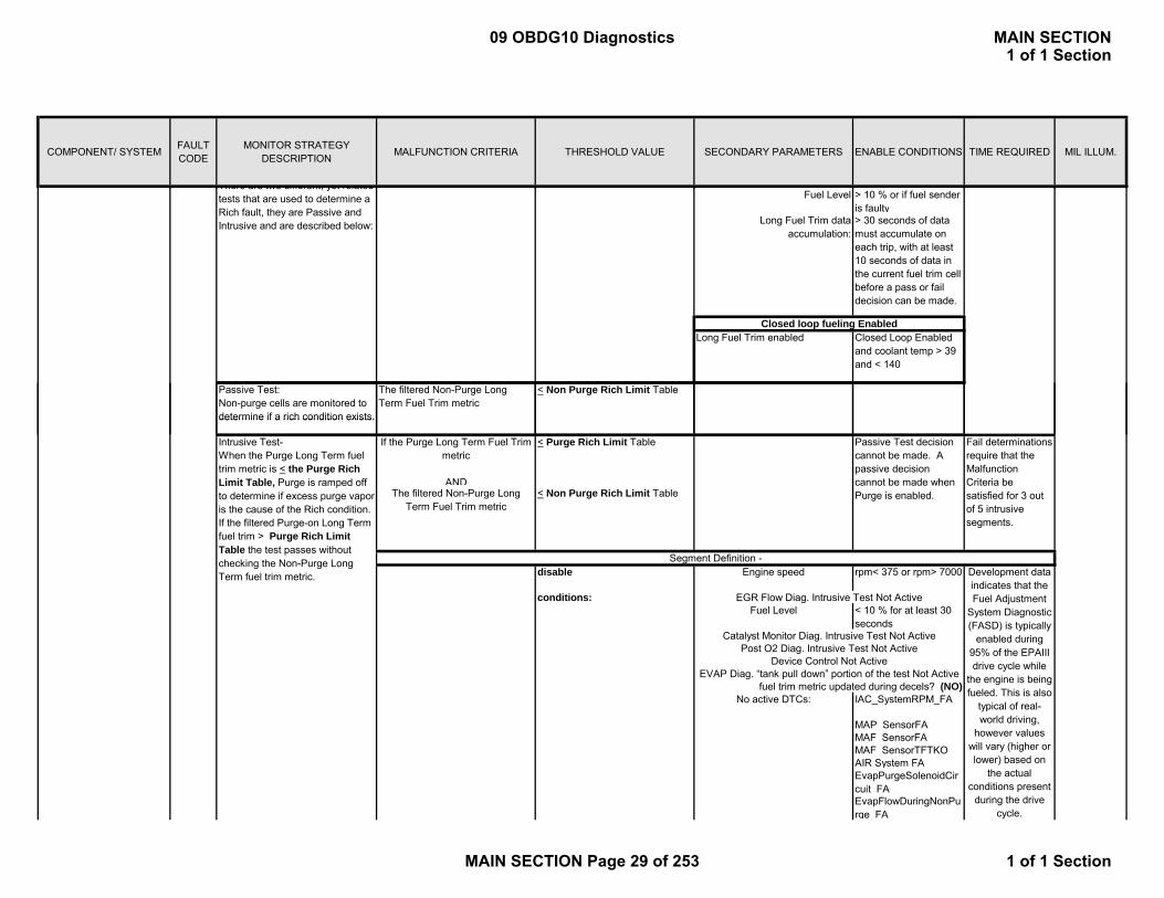
Fuel Level > 10 % or if fuel sender is faulty
Long Fuel Trim data accumulation:
> 30 seconds of data must accumulate on each trip, with at least 10 seconds of data in the current fuel trim cell before a pass or fail decision can be made.
Long Fuel Trim enabled Closed Loop Enabled and coolant temp > 39 and < 140
Passive Test: Non-purge cells are monitored to determine if a rich condition exists.
The filtered Non-Purge Long Term Fuel Trim metric
< Non Purge Rich Limit Table
There are two different, yet related tests that are used to determine a Rich fault, they are Passive and Intrusive and are described below:
Closed loop fueling Enabled
determine if a rich condition exists.
If the Purge Long Term Fuel Trim metric
AND
< Purge Rich Limit Table
The filtered Non-Purge Long Term Fuel Trim metric
< Non Purge Rich Limit Table
disable Engine speed rpm< 375 or rpm> 7000
conditions:Fuel Level < 10 % for at least 30
seconds
No active DTCs: IAC_SystemRPM_FA
MAP_SensorFAMAF_SensorFAMAF_SensorTFTKOAIR System FAEvapPurgeSolenoidCircuit FAEvapFlowDuringNonPurge FA
Intrusive Test- When the Purge Long Term fuel trim metric is < the Purge Rich Limit Table, Purge is ramped off to determine if excess purge vapor is the cause of the Rich condition. If the filtered Purge-on Long Term fuel trim > Purge Rich Limit Table the test passes without checking the Non-Purge Long Term fuel trim metric.
EGR Flow Diag. Intrusive Test Not Active
Catalyst Monitor Diag. Intrusive Test Not Active
Development data indicates that the Fuel Adjustment
System Diagnostic (FASD) is typically
enabled during 95% of the EPAIII drive cycle while
the engine is being fueled. This is also
typical of real-world driving,
however values will vary (higher or lower) based on
the actual conditions present
during the drive cycle.
Fail determinations require that the Malfunction Criteria be satisfied for 3 out of 5 intrusive segments.
Segment Definition -
Passive Test decision cannot be made. A passive decision cannot be made when Purge is enabled.
Device Control Not Active
fuel trim metric updated during decels? (NO)
Post O2 Diag. Intrusive Test Not Active
EVAP Diag. “tank pull down” portion of the test Not Active
09 OBDG10 Diagnostics MAIN SECTION1 of 1 Section
MAIN SECTION Page 29 of 253 1 of 1 Section

COMPONENT/ SYSTEM FAULT CODE
MONITOR STRATEGY DESCRIPTION MALFUNCTION CRITERIA THRESHOLD VALUE SECONDARY PARAMETERS ENABLE CONDITIONS TIME REQUIRED MIL ILLUM.
EvapVentSolenoidCircuit FAEvapSmallLeak_FAEvapEmissionSystem_FAFuelTankPressureSensorCircuit FAEthanol Composition Sensor FA
FuelInjectorCircuit_FA
EngineMisfireDetectedFA
EGRValvePerformanceFA
EGRValveCircuit_FAMAP_EngineVacuumStatusAmbientAirDefault_NA
Injector 1 P0201 This DTC checks the circuit for electrical integrity during operation.
The ECM detects that the commanded state of the driver and the actual state of the control ciruit do not match
Powertrain Relay Voltage within range and stable according to Enable Conditions Engine Running
11 volts ≤ Voltage ≤ 18 volts greater than 1 seconds
8 failures out of 10 samples250 ms /sampleContinuous
Type B2 trips
Injector 2 P0202 This DTC checks the circuit for electrical integrity during operation.
The ECM detects that the commanded state of the driver and the actual state of the control ciruit do not match
Powertrain Relay Voltage within range and stable according to Enable Conditions Engine Running
11 volts ≤ Voltage ≤ 18 volts greater than 1 seconds
8 failures out of 10 samples250 ms /sampleContinuous
Type B2 trips
Injector 3 P0203 This DTC checks the circuit for electrical integrity during operation.
The ECM detects that the commanded state of the driver and the actual state of the control ciruit do not match
Powertrain Relay Voltage within range and stable according to Enable Conditions Engine Running
11 volts ≤ Voltage ≤ 18 volts greater than 1 seconds
8 failures out of 10 samples250 ms /sampleContinuous
Type B2 trips
Injector 4 P0204 This DTC checks the circuit for electrical integrity during operation.
The ECM detects that the commanded state of the driver and the actual state of the control ciruit do not match
Powertrain Relay Voltage within range and stable according to Enable Conditions Engine Running
11 volts ≤ Voltage ≤ 18 volts greater than 1 seconds
8 failures out of 10 samples250 ms /sampleContinuous
Type B2 trips
Injector 5 P0205 This DTC checks the circuit for electrical integrity during operation.
The ECM detects that the commanded state of the driver and the actual state of the control ciruit do not match
Powertrain Relay Voltage within range and stable according to Enable Conditions Engine Running
11 volts ≤ Voltage ≤ 18 volts greater than 1 seconds
8 failures out of 10 samples250 ms /sampleContinuous
Type B2 trips
09 OBDG10 Diagnostics MAIN SECTION1 of 1 Section
MAIN SECTION Page 30 of 253 1 of 1 Section

COMPONENT/ SYSTEM FAULT CODE
MONITOR STRATEGY DESCRIPTION MALFUNCTION CRITERIA THRESHOLD VALUE SECONDARY PARAMETERS ENABLE CONDITIONS TIME REQUIRED MIL ILLUM.
Injector 6 P0206 This DTC checks the circuit for electrical integrity during operation.
The ECM detects that the commanded state of the driver and the actual state of the control ciruit do not match
Powertrain Relay Voltage within range and stable according to Enable Conditions Engine Running
11 volts ≤ Voltage ≤ 18 volts greater than 1 seconds
8 failures out of 10 samples250 ms /sampleContinuous
Type B2 trips
Injector 7 P0207 This DTC checks the circuit for electrical integrity during operation.
The ECM detects that the commanded state of the driver and the actual state of the control ciruit do not match
Powertrain Relay Voltage within range and stable according to Enable Conditions Engine Running
11 volts ≤ Voltage ≤ 18 volts greater than 1 seconds
8 failures out of 10 samples250 ms /sampleContinuous
Type B2 trips
Injector 8 P0208 This DTC checks the circuit for electrical integrity during operation.
The ECM detects that the commanded state of the driver and the actual state of the control ciruit do not match
Powertrain Relay Voltage within range and stable according to Enable Conditions Engine Running
11 volts ≤ Voltage ≤ 18 volts greater than 1 seconds
8 failures out of 10 samples250 ms /sampleContinuous
Type B2 trips
TPS2 Ci i S d TPS2 V l 0 2 R / k l T A 1P0220 D i 19/39 14TPS2 Circuit Secondary TPS2 Voltage < 0.25 Run/crank voltage or Powertrain relay voltage > 6.00 and reduced power is false, else the failure will be reported for all conditions
Type A 1 trip
or Secondary TPS2 Voltage > 4.59 No 5 V reference error
No 5 V reference DTCs
Primary TPS2 Voltage < 0.25 Run/crank voltage or Powertrain relay voltage > 6.00 and reduced power is false, else the failure will be reported for all conditions
Type A 1 trip
No 5 V reference error
Secondary TPS2 Voltage < 0.25 No 5 V reference DTCs
79/159 counts; 57 counts continuous; 3.125 msec /count in the Primary processor
19/39 counts or 14 counts continuous; 12.5 msec/count in the Secondary processor
TPS2 Circuit Low P0222
P0220
Detects a continuous or intermittent short in TPS2 circuit on both processors or just the primary processor
Detects a continuous or intermittent short or open in TPS2 circuit on the secondary processor but sensor is in range on the primary processor
19/39 counts or 14 counts continuous; 12.5 msec/count in the Secondary processor
09 OBDG10 Diagnostics MAIN SECTION1 of 1 Section
MAIN SECTION Page 31 of 253 1 of 1 Section

COMPONENT/ SYSTEM FAULT CODE
MONITOR STRATEGY DESCRIPTION MALFUNCTION CRITERIA THRESHOLD VALUE SECONDARY PARAMETERS ENABLE CONDITIONS TIME REQUIRED MIL ILLUM.
Primary TPS2 Voltage > 4.59 Run/crank voltage or Powertrain relay voltage > 6.00 and reduced power is false, else the failure will be reported for all conditions
Type A 1 trip
No 5 V reference error
Secondary TPS2 Voltage > 4.59 No 5 V reference DTCs
Run/Crank Voltage 11 volts ≤ Voltage ≤ 18 volts
8 failures out of 10 samples
Type B 2 trips
79/159 counts; 57 counts continuous; 3.125 msec /count in the Primary processor
P0223 Detects a continuous or intermittent short or open in TPS2 circuit on both processors or just the primary processor
This DTC checks the circuit for electrical integrity during
TPS2 Circuit High
The ECM detects that the commanded state of the driver
19/39 counts or 14 counts continuous; 12.5 msec/count in the Secondary processor
Fuel Pump Primary Circuit(ODM)
P0230volts samples trips
Engine Speed ≥ 0 RPM 250 ms /sampleContinuous
Engine Run Time > 2 crankshaft revolutions
Type B 2 trips
ECT -7ºC < ECT < 130ºC
If ECT at startup < -7ºC (Mil Flashes with Catalyst Damaging Misfire)
ECT 21ºC < ECT< 130ºC
System Voltage 9.00<volts<18.00+ Throttle delta < 75.00% per 25 ms- Throttle delta < 75.00% per 25 ms
Misfire Percent Emission Failure Threshold
≥ 1.24% P0300≥ 1.5% emission
electrical integrity during operation.
These DTC’s will determine if a random or a cylinder specific misfire is occurring by monitoring crankshaft velocity
commanded state of the driver and the actual state of the control circuit do not match.
Deceleration index vs. Engine Speed Vs Engine load
Deceleration index calculation is tailored to specific veh. Tables used are 1st tables encountered that are not max of range. Undetectable region at a given speed/load point is where all tables are max of range point. see Algorithm Description Document for additional details.
(ODM)
1st Catalyst Exceedence = (1) 200 rev block as data supports for catalyst damage. 2nd and subsequent Catalyst Exceedence = (1) 200 rev block with catalyst damage
Emission Exceedence = (5) failed 200 rev blocks of 16. Failure reported with (1) Exceedence in 1st (16) 200 rev block, or (4) Exceedences thereafter.
Random Misfire Detected
Cylinder 1 Misfire Detected
Cylinder 2 Misfire Detected
Cylinder 3 Misfire Detected
Cylinder 4 Misfire Detected
Cylinder 5 Misfire Detected
Cylinder 6 Misfire Detected
Cylinder 7 Misfire Detected
Cylinder 8 Misfire Detected
P0300
P0301
P0302
P0303
P0304
P0305
P0306
P0307
P0308
(>Idle SCD AND > Idle SCD ddt Tables)OR(>SCD Delta AND > SCD Delta ddt Tables)OR(>Idle Cyl Mode AND > Idle Cyl Mode ddt Tables)OR(>Cyl Mode AND > Cyl Mode ddt Tables)OR(>Rev Mode Table)OR (> AFM Table in Cyl Deact mode)
09 OBDG10 Diagnostics MAIN SECTION1 of 1 Section
MAIN SECTION Page 32 of 253 1 of 1 Section
COMPONENT/ SYSTEM FAULT CODE
MONITOR STRATEGY DESCRIPTION MALFUNCTION CRITERIA THRESHOLD VALUE SECONDARY PARAMETERS ENABLE CONDITIONS TIME REQUIRED MIL ILLUM.
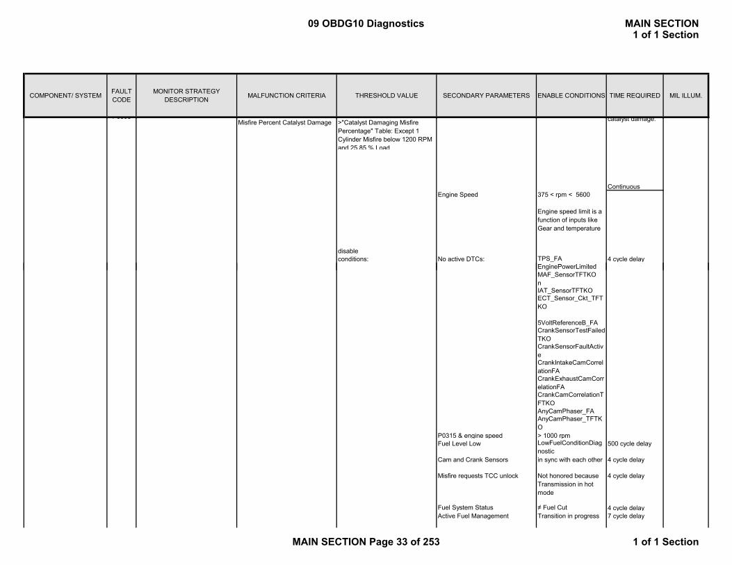
Misfire Percent Catalyst Damage >"Catalyst Damaging Misfire Percentage" Table: Except 1 Cylinder Misfire below 1200 RPM and 25.85 % Load
ContinuousEngine Speed 375 < rpm < 5600
Engine speed limit is a function of inputs like Gear and temperature
disableconditions: No active DTCs: TPS_FA 4 cycle delay
E i P Li it d
catalyst damage. P0308
EnginePowerLimitedMAF_SensorTFTKOnIAT_SensorTFTKOECT_Sensor_Ckt_TFTKO
5VoltReferenceB_FACrankSensorTestFailedTKOCrankSensorFaultActiveCrankIntakeCamCorrelationFACrankExhaustCamCorrelationFACrankCamCorrelationTFTKOAnyCamPhaser_FAAnyCamPhaser_TFTKO
P0315 & engine speed > 1000 rpmFuel Level Low LowFuelConditionDiag
nostic500 cycle delay
Cam and Crank Sensors in sync with each other 4 cycle delay
Misfire requests TCC unlock Not honored because Transmission in hot mode
4 cycle delay
Fuel System Status ≠ Fuel Cut 4 cycle delay Active Fuel Management Transition in progress 7 cycle delay
09 OBDG10 Diagnostics MAIN SECTION1 of 1 Section
MAIN SECTION Page 33 of 253 1 of 1 Section
COMPONENT/ SYSTEM FAULT CODE
MONITOR STRATEGY DESCRIPTION MALFUNCTION CRITERIA THRESHOLD VALUE SECONDARY PARAMETERS ENABLE CONDITIONS TIME REQUIRED MIL ILLUM.
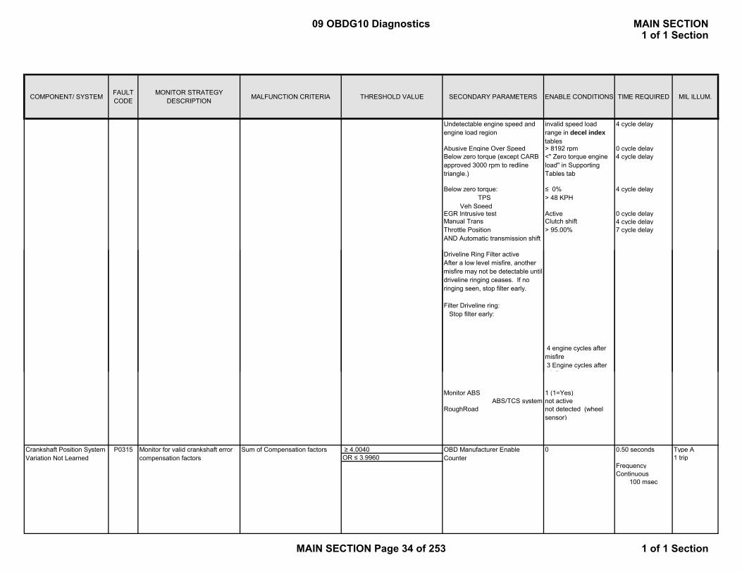
Undetectable engine speed and engine load region
invalid speed load range in decel index tables
4 cycle delay
Abusive Engine Over Speed > 8192 rpm 0 cycle delay Below zero torque (except CARB approved 3000 rpm to redline triangle.)
<" Zero torque engine load" in Supporting Tables tab
4 cycle delay
Below zero torque: TPS Veh Speed
≤ 0%> 48 KPH
4 cycle delay
EGR Intrusive test Active 0 cycle delay Manual Trans Clutch shift 4 cycle delay Throttle Position AND Automatic transmission shift
> 95.00% 7 cycle delay
Driveline Ring Filter active After a low level misfire, another misfire may not be detectable until driveline ringing ceases. If no ringing seen, stop filter early.
Filter Driveline ring: Stop filter early:
4 engine cycles after misfire 3 Engine cycles after
i fi
Monitor ABS 1 (1=Yes)ABS/TCS system not active
RoughRoad not detected (wheel sensor)
≥ 4.0040 0 Type AOR ≤ 3.9960 1 trip
FrequencyContinuous
100 msec
Crankshaft Position System Variation Not Learned
P0315 Monitor for valid crankshaft error compensation factors
OBD Manufacturer Enable Counter
Sum of Compensation factors 0.50 seconds
09 OBDG10 Diagnostics MAIN SECTION1 of 1 Section
MAIN SECTION Page 34 of 253 1 of 1 Section

COMPONENT/ SYSTEM FAULT CODE
MONITOR STRATEGY DESCRIPTION MALFUNCTION CRITERIA THRESHOLD VALUE SECONDARY PARAMETERS ENABLE CONDITIONS TIME REQUIRED MIL ILLUM.
P0324 > 4.50 Volts Engine Speed ≥ 400 RPM Type AEngine Air Flow > 60 mg/cylinder 1 tripNo Active DTC's KS_Ckt_Perf_B1B2_F
Aor
≤ 0.20 Volts Engine Speed ≥ 400 RPM 100 msec rateEngine Air Flow > 60 mg/cylinderNo Active DTC's KS_Ckt_Perf_B1B2_F
A
P0325 = 1
Engine Speed ≥ 400 RPMECT ≥ -40 deg. C 100 msec rateEnginer Run Time ≥ 2 secondsNo Active DTC's KS_Ckt_Perf_B1B2_F
ADisabled
50 Failures out of 63 Samples
Type: B2 trips
This diagnostic checks for an open in the knock sensor circuit
Power Take-Off Disabled
Diagnostic Enabled (1 = Enabled)
Knock Sensor (KS) Module Performance
This diagnostic will detect a failed internal ECM component associated with knock control
Any Cylinder’s Avg Gain Signal 50 Failures out of 63 Samples
All Cylinder’s Actual Signals
> 4.0 Volts or< 1.24 Volts
Gated Low Pass Filter VoltageKnock Sensor (KS) Circuit Bank 1
P0326 = 1
> 0100 msec rate
Engine Speed ≥ 500 RPM
MAP ≥ 10 kPaNo Active DTC's TPS_ThrottleAuthority
DefaultedDisabled
Knock Sensor (KS) Performance Bank 1
This diagnostic checks for an overactive knock sensor caused by excessive knock or noisy engine components
Power Take-Off Disabled
Type: B2 trips
Knock Detection EnabledKnock Detection Enabled is calculated by multiplying the following three factors: FastAttackRate FastAttackCoolGain FastAttackBaroGain(see Supporting Tables)
Knock Fast Retard (spark degrees) >
> (FastRtdMax + 6.0 degrees - 2.0) degrees spark
31 Failures out of 63 Samples
Diagnostic Enabled (1 = Enabled)
See Supporting Tables for FastRtdMax
09 OBDG10 Diagnostics MAIN SECTION1 of 1 Section
MAIN SECTION Page 35 of 253 1 of 1 Section

COMPONENT/ SYSTEM FAULT CODE
MONITOR STRATEGY DESCRIPTION MALFUNCTION CRITERIA THRESHOLD VALUE SECONDARY PARAMETERS ENABLE CONDITIONS TIME REQUIRED MIL ILLUM.
P0327 > 2.86 Volts ECT ≥ -40 deg. CEnginer Run Time ≥ 2 seconds
or Engine Oil Temp < 256 deg. C< 1.48 Volts No Active DTC's EngOilModeledTempV
alid100 msec rate
P0328 < 2.02 Volts ECT ≥ -40 deg. CEnginer Run Time ≥ 2 seconds
or Engine Oil Temp < 256 deg. C> 3.76 Volts No Active DTC's EngOilModeledTempV
alid100 msec rate
P0330 = 1
Engine Speed ≥ 400 RPMECT ≥ -40 deg. C 100 msec rateE i R Ti ≥ 2 d
Type: B2 trips
Type: B2 tripsKnock Sensor (KS) Circuit
Low Bank 1This diagnostic checks for an out of range low knock sensor signal
Knock Sensor (KS) Circuit High Bank 1
This diagnostic checks for an open in the knock sensor circuit
Sensor Input Signal Line
This diagnostic checks for an out of range high knock sensor signal
Knock Sensor (KS) Circuit Bank 2
Sensor Return Signal Line
Diagnostic Enabled (1 = Enabled)
50 Failures out of 63 Samples
50 Failures out of 63 Samples
Sensor Return Signal Line
Type: B2 trips
Sensor Input Signal Line
Gated Low Pass Filter Voltage> 4.0 Volts or< 1.24 Volts
50 Failures out of 63 Samples
Enginer Run Time ≥ 2 secondsNo Active DTC's KS_Ckt_Perf_B1B2_F
ADisabled
P0332 > 2.86 Volts ECT ≥ -40 deg. CEnginer Run Time ≥ 2 seconds
or Engine Oil Temp < 256 deg. C< 1.48 Volts No Active DTC's EngOilModeledTempV
alid100 msec rate
P0333 < 2.02 Volts ECT ≥ -40 deg. CEnginer Run Time ≥ 2 seconds
or Engine Oil Temp < 256 deg. C> 3.76 Volts No Active DTC's EngOilModeledTempV
alid100 msec rate
Starter engagedAND
OR( DTC P0101 = FALSEAND DTC P0102 = FALSEAND DTC P0103 = FALSE
Type: B2 trips
Type A1 trip
Sensor Return Signal Line
50 Failures out of 63 Samples
Engine-Cranking Crankshaft Test:
Time since last crankshaft position sensor pulse received
>= 4.0 seconds
Sensor Input Signal Line
Sensor Return Signal Line
Continuous every 100 msec
Knock Sensor (KS) Circuit Low Bank 2
This diagnostic checks for an out of range low knock sensor signal
Sensor Input Signal Line
Knock Sensor (KS) Circuit High Bank 2
This diagnostic checks for an out of range high knock sensor signal
(cam pulses being received
Power Take-Off Disabled
Crankshaft Position (CKP) Sensor A Circuit
P0335 Determines if a fault exists with the crank position sensor signal
Engine-Cranking Crankshaft Test: Engine-Cranking Crankshaft Test:
50 Failures out of 63 Samples
Type: B2 trips
09 OBDG10 Diagnostics MAIN SECTION1 of 1 Section
MAIN SECTION Page 36 of 253 1 of 1 Section
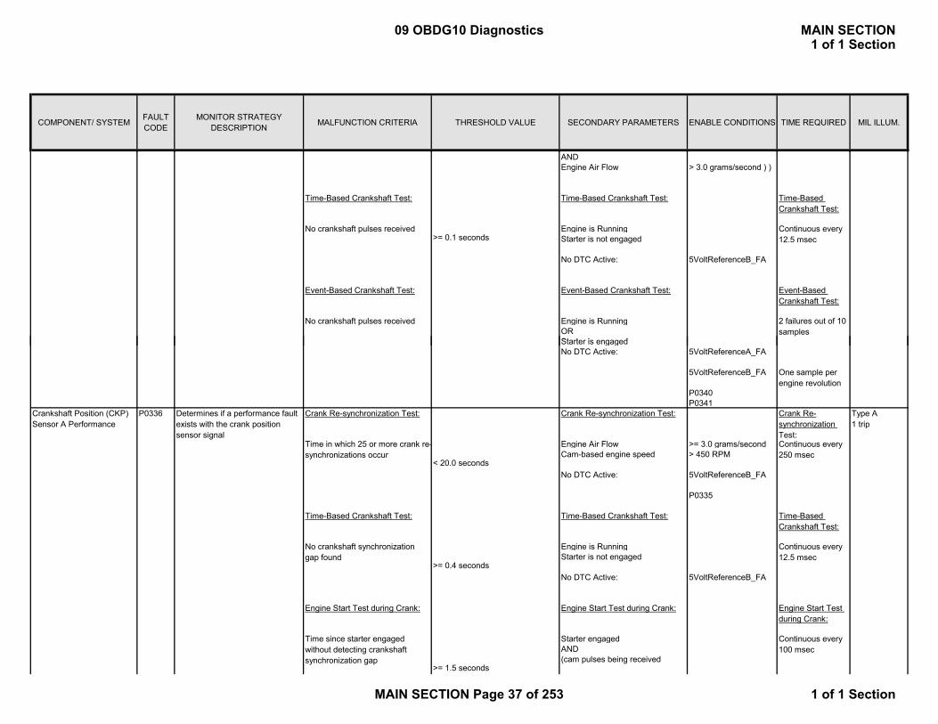
COMPONENT/ SYSTEM FAULT CODE
MONITOR STRATEGY DESCRIPTION MALFUNCTION CRITERIA THRESHOLD VALUE SECONDARY PARAMETERS ENABLE CONDITIONS TIME REQUIRED MIL ILLUM.
ANDEngine Air Flow > 3.0 grams/second ) )
Engine is Running
No DTC Active: 5VoltReferenceB_FA
Engine is RunningORSt t i d
Event-Based Crankshaft Test:
Time-Based Crankshaft Test:
Event-Based Crankshaft Test:
Continuous every 12.5 msecStarter is not engaged
2 failures out of 10 samples
Time-Based Crankshaft Test:
No crankshaft pulses received>= 0.1 seconds
Time-Based Crankshaft Test:
Event-Based Crankshaft Test:
No crankshaft pulses received
Starter is engagedNo DTC Active: 5VoltReferenceA_FA
5VoltReferenceB_FA
P0340P0341
Engine Air Flow >= 3.0 grams/second
No DTC Active: 5VoltReferenceB_FA
P0335
Engine is Running
No DTC Active: 5VoltReferenceB_FA
Starter engagedAND
Crank Re-synchronization Test: Type A1 trip
>= 0.4 seconds
Continuous every 12.5 msecStarter is not engaged
P0336 Determines if a performance fault exists with the crank position sensor signal
Crank Re-synchronization Test:Crankshaft Position (CKP) Sensor A Performance
Time in which 25 or more crank re-synchronizations occur
Time-Based Crankshaft Test:
Engine Start Test during Crank:
Crank Re-synchronization Test:
One sample per engine revolution
Time since starter engaged without detecting crankshaft synchronization gap
< 20.0 seconds
Time-Based Crankshaft Test:
Cam-based engine speed > 450 RPM
Engine Start Test during Crank:
No crankshaft synchronization gap found
>= 1.5 seconds
Continuous every 100 msec
(cam pulses being received
Continuous every 250 msec
Engine Start Test during Crank:
Time-Based Crankshaft Test:
09 OBDG10 Diagnostics MAIN SECTION1 of 1 Section
MAIN SECTION Page 37 of 253 1 of 1 Section
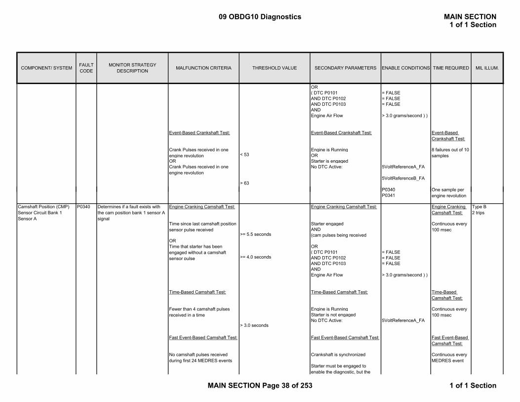
COMPONENT/ SYSTEM FAULT CODE
MONITOR STRATEGY DESCRIPTION MALFUNCTION CRITERIA THRESHOLD VALUE SECONDARY PARAMETERS ENABLE CONDITIONS TIME REQUIRED MIL ILLUM.
OR( DTC P0101 = FALSEAND DTC P0102 = FALSEAND DTC P0103 = FALSEANDEngine Air Flow > 3.0 grams/second ) )
Engine is RunningOR
OR Starter is engagedNo DTC Active: 5VoltReferenceA_FA
5VoltReferenceB_FA
P0340
Crank Pulses received in one engine revolution
Crank Pulses received in one engine revolution
Event-Based Crankshaft Test: Event-Based Crankshaft Test:
< 538 failures out of 10 samples
> 63
Event-Based Crankshaft Test:
O lP0340P0341
Starter engagedAND
OROR( DTC P0101 = FALSEAND DTC P0102 = FALSEAND DTC P0103 = FALSEANDEngine Air Flow > 3.0 grams/second ) )
Engine is RunningStarter is not engagedNo DTC Active: 5VoltReferenceA_FA
Type B2 trips
Determines if a fault exists with the cam position bank 1 sensor A signal
Camshaft Position (CMP) Sensor Circuit Bank 1 Sensor A
P0340
(cam pulses being received>= 5.5 seconds
Engine Cranking Camshaft Test:
>= 4.0 seconds
Time-Based Camshaft Test:
Engine Cranking Camshaft Test:
Time since last camshaft position sensor pulse received
Time that starter has been engaged without a camshaft sensor pulse
Fast Event-Based Camshaft Test:
Crankshaft is synchronizedNo camshaft pulses received during first 24 MEDRES events
Fewer than 4 camshaft pulses received in a time
Fast Event-Based Camshaft Test:
Starter must be engaged to enable the diagnostic, but the
> 3.0 seconds
Time-Based Camshaft Test: Time-Based Camshaft Test:
Engine Cranking Camshaft Test:
Fast Event-Based Camshaft Test:
Continuous every MEDRES event
Continuous every 100 msec
Continuous every 100 msec
One sample per engine revolution
09 OBDG10 Diagnostics MAIN SECTION1 of 1 Section
MAIN SECTION Page 38 of 253 1 of 1 Section
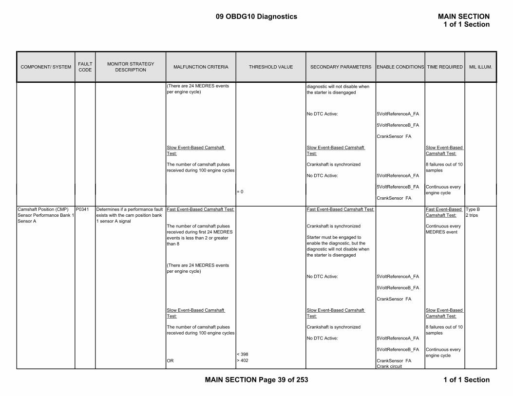
COMPONENT/ SYSTEM FAULT CODE
MONITOR STRATEGY DESCRIPTION MALFUNCTION CRITERIA THRESHOLD VALUE SECONDARY PARAMETERS ENABLE CONDITIONS TIME REQUIRED MIL ILLUM.
No DTC Active: 5VoltReferenceA_FA
5VoltReferenceB_FA
CrankSensor_FA
No DTC Active: 5VoltReferenceA_FA
5V ltR f B FA
diagnostic will not disable when the starter is disengaged
(There are 24 MEDRES events per engine cycle)
Slow Event-Based Camshaft Test:
Slow Event-Based Camshaft Test:
The number of camshaft pulses received during 100 engine cycles
Crankshaft is synchronized
Slow Event-Based Camshaft Test:
C ti
8 failures out of 10 samples
5VoltReferenceB_FA
CrankSensor_FA
No DTC Active: 5VoltReferenceA_FA
5VoltReferenceB_FA
CrankSensor_FA
No DTC Active: 5VoltReferenceA_FA
5VoltReferenceB_FA
OR > 402 CrankSensor_FACrank circuit
Slow Event-Based Camshaft Test:
< 398
The number of camshaft pulses received during first 24 MEDRES events is less than 2 or greater than 8
Continuous every MEDRES event
Starter must be engaged to enable the diagnostic, but the diagnostic will not disable when the starter is disengaged
Fast Event-Based Camshaft Test:
Crankshaft is synchronized
P0341 Determines if a performance fault exists with the cam position bank 1 sensor A signal
Slow Event-Based Camshaft Test:
The number of camshaft pulses received during 100 engine cycles
Type B2 trips
Camshaft Position (CMP) Sensor Performance Bank 1 Sensor A
Fast Event-Based Camshaft Test:
(There are 24 MEDRES events per engine cycle)
Fast Event-Based Camshaft Test:
Slow Event-Based Camshaft Test:
= 0Continuous every engine cycle
Crankshaft is synchronized 8 failures out of 10 samples
Continuous every engine cycle
09 OBDG10 Diagnostics MAIN SECTION1 of 1 Section
MAIN SECTION Page 39 of 253 1 of 1 Section
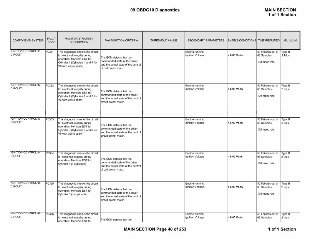
COMPONENT/ SYSTEM FAULT CODE
MONITOR STRATEGY DESCRIPTION MALFUNCTION CRITERIA THRESHOLD VALUE SECONDARY PARAMETERS ENABLE CONDITIONS TIME REQUIRED MIL ILLUM.
P0351 Engine runningIgnition Voltage > 6.00 Volts
100 msec rate
P0352 Engine runningIgnition Voltage > 6.00 Volts
100 msec rate
Type B2 trips
Type B2 Trips
IGNITION CONTROL #1 CIRCUIT
The ECM detects that the commanded state of the driver and the actual state of the control circuit do not match.
This diagnostic checks the circuit for electrical integrity during operation. Monitors EST for Cylinder 1 (Cylinders 1 and 4 for V6 with waste spark)
The ECM detects that the commanded state of the driver and the actual state of the control circuit do not match.
50 Failures out of 63 Samples
50 Failures out of 63 Samples
IGNITION CONTROL #2 CIRCUIT
This diagnostic checks the circuit for electrical integrity during operation. Monitors EST for Cylinder 2 (Cylinders 2 and 5 for V6 with waste spark)
P0353 Engine runningIgnition Voltage > 6.00 Volts
100 msec rate
P0354 Engine runningIgnition Voltage > 6.00 Volts
100 msec rate
P0355 Engine runningIgnition Voltage > 6.00 Volts
100 msec rate
P0356 Engine runningIgnition Voltage > 6.00 Volts
The ECM detects that the commanded state of the driver and the actual state of the control circuit do not match.
50 Failures out of 63 Samples
Type B2 trips
IGNITION CONTROL #3 CIRCUIT
This diagnostic checks the circuit for electrical integrity during operation. Monitors EST for Cylinder 3 (Cylinders 3 and 6 for V6 with waste spark)
IGNITION CONTROL #6 CIRCUIT
This diagnostic checks the circuit for electrical integrity during operation. Monitors EST for The ECM detects that the
d d t t f th d i
50 Failures out of 63 Samples
Type B2 trips
Type B2 trips
IGNITION CONTROL #4 CIRCUIT
This diagnostic checks the circuit for electrical integrity during operation. Monitors EST for Cylinder 4 (if applicable)
The ECM detects that the commanded state of the driver and the actual state of the control circuit do not match.
50 Failures out of 63 Samples
IGNITION CONTROL #5 CIRCUIT
This diagnostic checks the circuit for electrical integrity during operation. Monitors EST for Cylinder 5 (if applicable)
The ECM detects that the commanded state of the driver and the actual state of the control circuit do not match.
50 Failures out of 63 Samples
Type B2 trips
09 OBDG10 Diagnostics MAIN SECTION1 of 1 Section
MAIN SECTION Page 40 of 253 1 of 1 Section
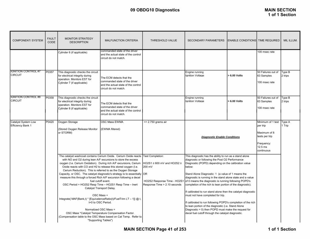
COMPONENT/ SYSTEM FAULT CODE
MONITOR STRATEGY DESCRIPTION MALFUNCTION CRITERIA THRESHOLD VALUE SECONDARY PARAMETERS ENABLE CONDITIONS TIME REQUIRED MIL ILLUM.
100 msec rate
P0357 Engine runningIgnition Voltage > 6.00 Volts
100 msec rate
P0358 Engine runningIgnition Voltage > 6.00 Volts
100 msec rateThe ECM detects that the commanded state of the driver and the actual state of the control
IGNITION CONTROL #8 CIRCUIT
This diagnostic checks the circuit for electrical integrity during operation. Monitors EST for Cylinder 8 (if applicable)
pCylinder 6 (if applicable) commanded state of the driver
and the actual state of the control circuit do not match.
IGNITION CONTROL #7 CIRCUIT
This diagnostic checks the circuit for electrical integrity during operation. Monitors EST for Cylinder 7 (if applicable)
The ECM detects that the commanded state of the driver and the actual state of the control circuit do not match.
50 Failures out of 63 Samples
50 Failures out of 63 Samples
Type B2 trips
Type B2 trips
Catalyst System Low Efficiency Bank 1
Oxygen Storage
(Stored Oxygen Release Monitor or STORM)
OSC Mass EWMA
(EWMA filtered)
<= 2.750 grams air Minimum of 1 test per trip
Maximum of 8 tests per trip
Frequency:12.5 ms continuous
Type A1 Trip
Test Completion:
HO2S1 ≥ 600 mV and HO2S2 ≥ 200 mV
OR
HO2S2 Response Time - HO2S1 Response Time > 2.10 seconds
The catalyst washcoat contains Cerium Oxide. Cerium Oxide reacts with NO and O2 during lean A/F excursions to store the excess
oxygen (I.e. Cerium Oxidation). During rich A/F excursions, Cerium Oxide reacts with CO and H2 to release this stored oxygen (I.e. Cerium Reduction). This is referred to as the Oxygen Storage
Capacity, or OSC. The catalyst diagnostic's strategy is to essentially measure this through a forced Rich A/F excursion following a decel
fuel cutoff event.OSC Period = HO2S2 Resp Time – HO2S1 Resp Time – Inert
Catalyst Transport Delay.
OSC Mass =Integrate{ MAF(Bank,t) * [EquivalenceRatio(t)/FuelTrim LT – 1]} @ t,
t=0 to OSC Period.
Normalized OSC Mass = OSC Mass *Catalyst Temperature Compensation Factor.
(Compensation table to the OSC Mass based on Cat Temp. Refer to "Supporting Tables")
and the actual state of the control circuit do not match.
This diagnostic has the ability to run as a stand alone diagnostic or following the Post O2 Performance Diagnostic (POPD) depending on the calibration value below:
Stand Alone Diagnostic: 1 (a value of 1 means the diagnostic is running in the stand alone state and a value of 0 means the diagnostic is running following POPD's completion of the rich to lean portion of the diagnostic).
If calibrated to run stand alone then the catalyst diagnostic must not have completed for trip.
If calibrated to run following POPD's completion of the rich to lean portion of the diagnostic (i.e. Stand Alone Diagnostic = 0) then POPD must make the request for decel fuel cutoff through the catalyst diagnostic.
P0420
Diagnostic Enable Conditions
09 OBDG10 Diagnostics MAIN SECTION1 of 1 Section
MAIN SECTION Page 41 of 253 1 of 1 Section
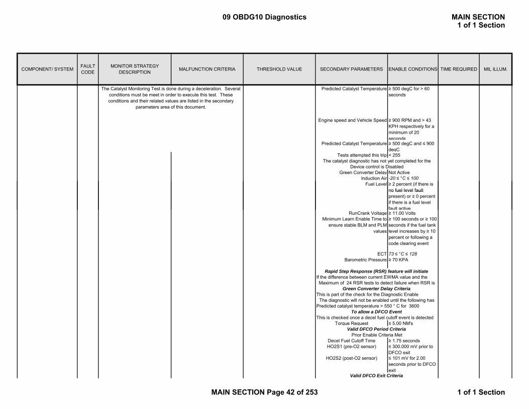
COMPONENT/ SYSTEM FAULT CODE
MONITOR STRATEGY DESCRIPTION MALFUNCTION CRITERIA THRESHOLD VALUE SECONDARY PARAMETERS ENABLE CONDITIONS TIME REQUIRED MIL ILLUM.
Predicted Catalyst Temperature ≥ 500 degC for > 60 seconds
Engine speed and Vehicle Speed ≥ 900 RPM and > 43 KPH respectively for a minimum of 20 seconds
Predicted Catalyst Temperature ≥ 500 degC and ≤ 900 degC
Tests attempted this trip < 255
Green Converter Delay Not ActiveInduction Air -20 ≤ °C ≤ 100
Fuel Level ≥ 2 percent (if there is no fuel level fault
The Catalyst Monitoring Test is done during a deceleration. Several conditions must be meet in order to execute this test. These conditions and their related values are listed in the secondary
parameters area of this document.
Device control is DisabledThe catalyst diagnostic has not yet completed for the
no fuel level fault present) or ≥ 0 percent if there is a fuel level fault active
RunCrank Voltage ≥ 11.00 VoltsMinimum Learn Enable Time to
ensure stable BLM and PLM values
≥ 100 seconds or ≥ 100 seconds if the fuel tank level increases by ≥ 10 percent or following a code clearing event
ECT 73 ≤ °C ≤ 128Barometric Pressure ≥ 70 KPA
Torque Request ≤ 5.00 NM's
Decel Fuel Cutoff Time ≥ 1.75 secondsHO2S1 (pre-O2 sensor) ≤ 300.000 mV prior to
DFCO exitHO2S2 (post-O2 sensor) ≤ 101 mV for 2.00
seconds prior to DFCO exit
Rapid Step Response (RSR) feature will initiate
This is part of the check for the Diagnostic Enable
To allow a DFCO Event
Valid DFCO Period CriteriaPrior Enable Criteria Met
Valid DFCO Exit Criteria
This is checked once a decel fuel cutoff event is detected
Green Converter Delay Criteria
If the difference between current EWMA value and the Maximum of 24 RSR tests to detect failure when RSR is
The diagnostic will not be enabled until the following has Predicted catalyst temperature > 550 ° C for 3600
09 OBDG10 Diagnostics MAIN SECTION1 of 1 Section
MAIN SECTION Page 42 of 253 1 of 1 Section
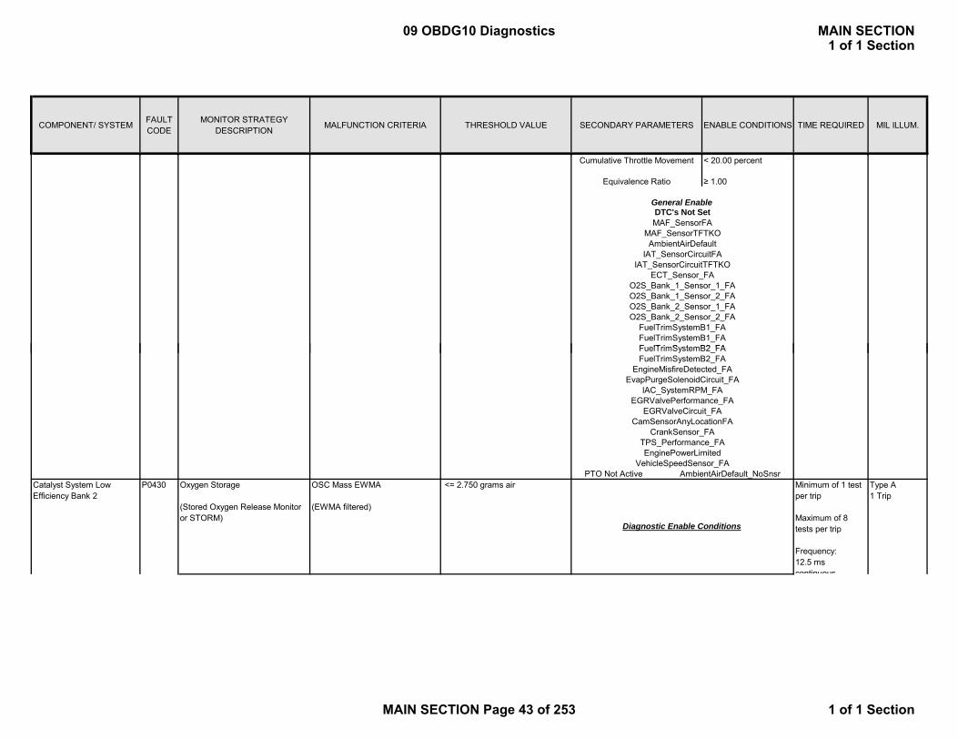
COMPONENT/ SYSTEM FAULT CODE
MONITOR STRATEGY DESCRIPTION MALFUNCTION CRITERIA THRESHOLD VALUE SECONDARY PARAMETERS ENABLE CONDITIONS TIME REQUIRED MIL ILLUM.
Cumulative Throttle Movement < 20.00 percent
Equivalence Ratio ≥ 1.00
General Enable
O2S_Bank_2_Sensor_2_FAFuelTrimSystemB1_FAFuelTrimSystemB1_FAFuelTrimSystemB2 FA
O2S_Bank_1_Sensor_2_FA
IAT_SensorCircuitFAIAT_SensorCircuitTFTKO
O2S_Bank_2_Sensor_1_FA
DTC's Not SetMAF_SensorFA
MAF_SensorTFTKOAmbientAirDefault
ECT_Sensor_FAO2S_Bank_1_Sensor_1_FA
Catalyst System Low Efficiency Bank 2
Oxygen Storage
(Stored Oxygen Release Monitor or STORM)
OSC Mass EWMA
(EWMA filtered)
<= 2.750 grams air Minimum of 1 test per trip
Maximum of 8 tests per trip
Frequency:12.5 ms continuous
Type A1 Trip
P0430
TPS_Performance_FAEnginePowerLimited
CrankSensor_FA
FuelTrimSystemB2_FA
EGRValvePerformance_FAIAC_SystemRPM_FA
FuelTrimSystemB2_FAEngineMisfireDetected_FA
EvapPurgeSolenoidCircuit_FA
PTO Not Active AmbientAirDefault_NoSnsr
Diagnostic Enable Conditions
VehicleSpeedSensor_FA
EGRValveCircuit_FA CamSensorAnyLocationFA
09 OBDG10 Diagnostics MAIN SECTION1 of 1 Section
MAIN SECTION Page 43 of 253 1 of 1 Section
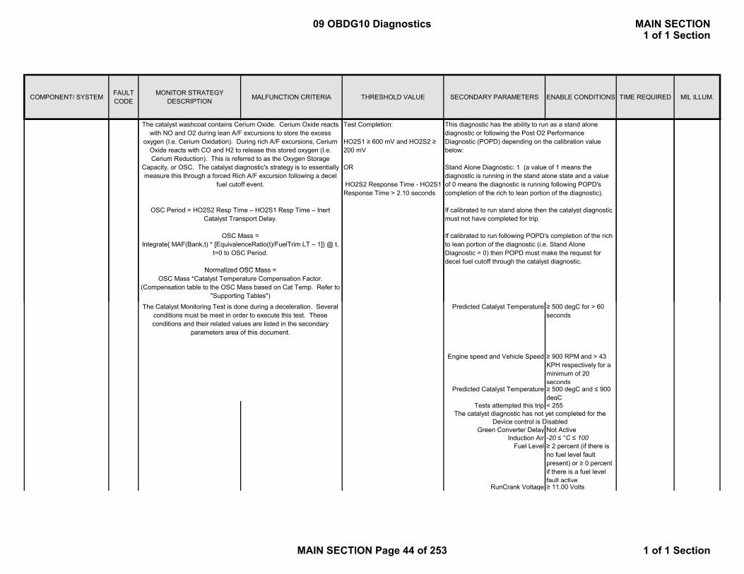
COMPONENT/ SYSTEM FAULT CODE
MONITOR STRATEGY DESCRIPTION MALFUNCTION CRITERIA THRESHOLD VALUE SECONDARY PARAMETERS ENABLE CONDITIONS TIME REQUIRED MIL ILLUM.
Test Completion:
HO2S1 ≥ 600 mV and HO2S2 ≥ 200 mV
OR
HO2S2 Response Time - HO2S1 Response Time > 2.10 seconds
This diagnostic has the ability to run as a stand alone diagnostic or following the Post O2 Performance Diagnostic (POPD) depending on the calibration value below:
Stand Alone Diagnostic: 1 (a value of 1 means the diagnostic is running in the stand alone state and a value of 0 means the diagnostic is running following POPD's completion of the rich to lean portion of the diagnostic).
If calibrated to run stand alone then the catalyst diagnostic must not have completed for trip.
If calibrated to run following POPD's completion of the rich to lean portion of the diagnostic (i.e. Stand Alone Diagnostic = 0) then POPD must make the request for decel fuel cutoff through the catalyst diagnostic.
The catalyst washcoat contains Cerium Oxide. Cerium Oxide reacts with NO and O2 during lean A/F excursions to store the excess
oxygen (I.e. Cerium Oxidation). During rich A/F excursions, Cerium Oxide reacts with CO and H2 to release this stored oxygen (I.e. Cerium Reduction). This is referred to as the Oxygen Storage
Capacity, or OSC. The catalyst diagnostic's strategy is to essentially measure this through a forced Rich A/F excursion following a decel
fuel cutoff event.
OSC Period = HO2S2 Resp Time – HO2S1 Resp Time – Inert Catalyst Transport Delay.
OSC Mass =Integrate{ MAF(Bank,t) * [EquivalenceRatio(t)/FuelTrim LT – 1]} @ t,
t=0 to OSC Period.
Normalized OSC Mass =
Predicted Catalyst Temperature ≥ 500 degC for > 60 seconds
Engine speed and Vehicle Speed ≥ 900 RPM and > 43 KPH respectively for a minimum of 20 seconds
Predicted Catalyst Temperature ≥ 500 degC and ≤ 900 degC
Tests attempted this trip < 255
Green Converter Delay Not ActiveInduction Air -20 ≤ °C ≤ 100
Fuel Level ≥ 2 percent (if there is no fuel level fault present) or ≥ 0 percent if there is a fuel level fault active
RunCrank Voltage ≥ 11.00 Volts
Normalized OSC Mass = OSC Mass *Catalyst Temperature Compensation Factor.
(Compensation table to the OSC Mass based on Cat Temp. Refer to "Supporting Tables")
The Catalyst Monitoring Test is done during a deceleration. Several conditions must be meet in order to execute this test. These conditions and their related values are listed in the secondary
parameters area of this document.
The catalyst diagnostic has not yet completed for the Device control is Disabled
09 OBDG10 Diagnostics MAIN SECTION1 of 1 Section
MAIN SECTION Page 44 of 253 1 of 1 Section
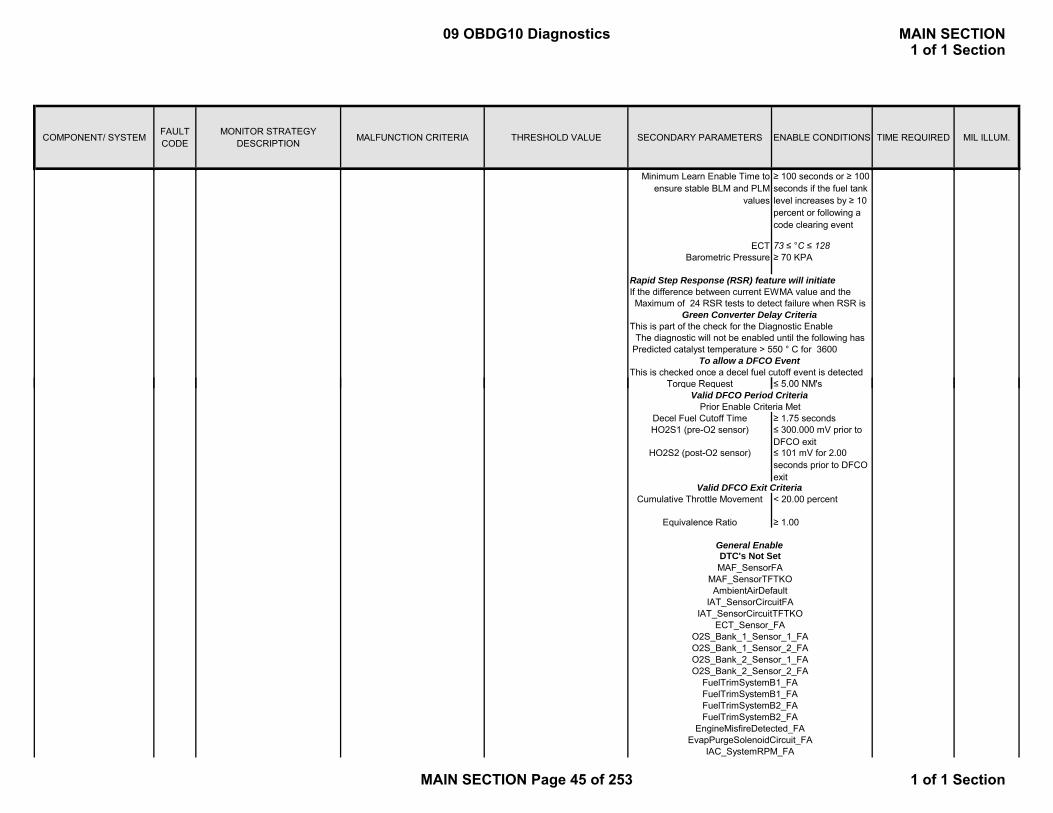
COMPONENT/ SYSTEM FAULT CODE
MONITOR STRATEGY DESCRIPTION MALFUNCTION CRITERIA THRESHOLD VALUE SECONDARY PARAMETERS ENABLE CONDITIONS TIME REQUIRED MIL ILLUM.
Minimum Learn Enable Time to ensure stable BLM and PLM
values
≥ 100 seconds or ≥ 100 seconds if the fuel tank level increases by ≥ 10 percent or following a code clearing event
ECT 73 ≤ °C ≤ 128Barometric Pressure ≥ 70 KPA
T R t ≤ 5 00 NM'
Green Converter Delay Criteria
This is checked once a decel fuel cutoff event is detected To allow a DFCO Event
Maximum of 24 RSR tests to detect failure when RSR is
This is part of the check for the Diagnostic Enable The diagnostic will not be enabled until the following has
Predicted catalyst temperature > 550 ° C for 3600
Rapid Step Response (RSR) feature will initiate If the difference between current EWMA value and the
Torque Request ≤ 5.00 NM's
Decel Fuel Cutoff Time ≥ 1.75 secondsHO2S1 (pre-O2 sensor) ≤ 300.000 mV prior to
DFCO exitHO2S2 (post-O2 sensor) ≤ 101 mV for 2.00
seconds prior to DFCO exit
Cumulative Throttle Movement < 20.00 percent
Equivalence Ratio ≥ 1.00
Valid DFCO Period Criteria
DTC's Not SetMAF_SensorFA
MAF_SensorTFTKO
O2S_Bank_1_Sensor_2_FAO2S_Bank_2_Sensor_1_FAO2S_Bank_2_Sensor_2_FA
FuelTrimSystemB1_FA
FuelTrimSystemB2_FAEngineMisfireDetected_FA
IAT_SensorCircuitTFTKOECT_Sensor_FA
O2S_Bank_1_Sensor_1_FA
AmbientAirDefault
Prior Enable Criteria Met
Valid DFCO Exit Criteria
General Enable
IAT_SensorCircuitFA
FuelTrimSystemB1_FAFuelTrimSystemB2_FA
EvapPurgeSolenoidCircuit_FAIAC_SystemRPM_FA
09 OBDG10 Diagnostics MAIN SECTION1 of 1 Section
MAIN SECTION Page 45 of 253 1 of 1 Section
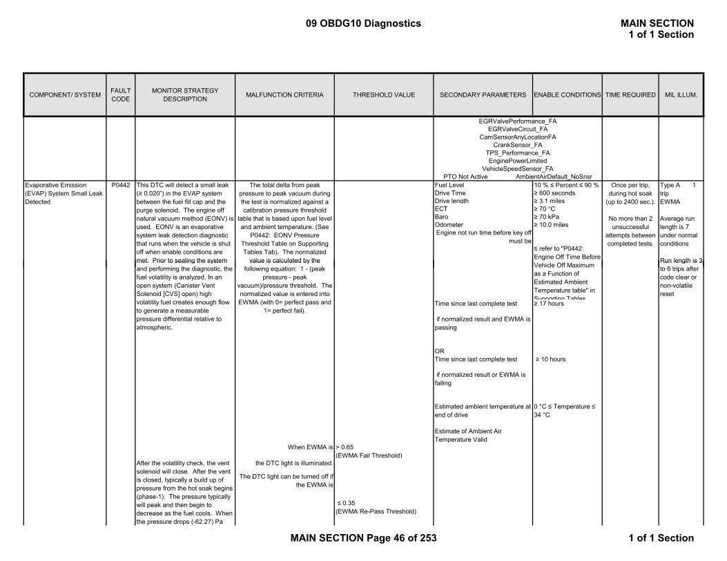
COMPONENT/ SYSTEM FAULT CODE
MONITOR STRATEGY DESCRIPTION MALFUNCTION CRITERIA THRESHOLD VALUE SECONDARY PARAMETERS ENABLE CONDITIONS TIME REQUIRED MIL ILLUM.
Fuel Level 10 % ≤ Percent ≤ 90 %Drive Time ≥ 600 secondsDrive length ≥ 3.1 milesECT ≥ 70 °CBaro ≥ 70 kPaOdometer ≥ 10.0 miles
The total delta from peak pressure to peak vacuum during the test is normalized against a calibration pressure threshold
table that is based upon fuel level and ambient temperature. (See
P0442: EONV Pressure Threshold Table on Supporting Tables Tab). The normalized
value is calculated by the
Type A 1 tripEWMA
Average run length is 7 under normal conditions
Run length is 3
Engine not run time before key off must be
≤ refer to "P0442: Engine Off Time Before V hi l Off M i
Evaporative Emission (EVAP) System Small Leak Detected
P0442 This DTC will detect a small leak (≥ 0.020”) in the EVAP system between the fuel fill cap and the purge solenoid. The engine off natural vacuum method (EONV) is used. EONV is an evaporative system leak detection diagnostic that runs when the vehicle is shut off when enable conditions are met. Prior to sealing the system
EGRValvePerformance_FA
Once per trip, during hot soak
(up to 2400 sec.).
No more than 2 unsuccessful
attempts between completed tests.
TPS_Performance_FAEnginePowerLimited
VehicleSpeedSensor_FAPTO Not Active AmbientAirDefault_NoSnsr
EGRValveCircuit_FA CamSensorAnyLocationFA
CrankSensor_FA
Time since last complete test ≥ 17 hours
if normalized result and EWMA is passing
ORTime since last complete test ≥ 10 hours
if normalized result or EWMA is failing
Estimated ambient temperature at end of drive
0 °C ≤ Temperature ≤ 34 °C
Estimate of Ambient Air Temperature Valid
When EWMA is > 0.65 (EWMA Fail Threshold)
the DTC light is illuminated.
value is calculated by the following equation: 1 - (peak
pressure - peak vacuum)/pressure threshold. The normalized value is entered into EWMA (with 0= perfect pass and
1= perfect fail).
Run length is 3 to 6 trips after code clear or non-volatile reset
Vehicle Off Maximum as a Function of Estimated Ambient Temperature table" in Supporting Tables
met. Prior to sealing the system and performing the diagnostic, the fuel volatility is analyzed. In an open system (Canister Vent Solenoid [CVS] open) high volatility fuel creates enough flow to generate a measurable pressure differential relative to atmospheric.
After the volatility check, the vent solenoid will close. After the vent is closed, typically a build up of pressure from the hot soak begins (phase-1). The pressure typically will peak and then begin to decrease as the fuel cools. When the pressure drops (-62.27) Pa
The DTC light can be turned off if the EWMA is
≤ 0.35(EWMA Re-Pass Threshold)
09 OBDG10 Diagnostics MAIN SECTION1 of 1 Section
MAIN SECTION Page 46 of 253 1 of 1 Section

COMPONENT/ SYSTEM FAULT CODE
MONITOR STRATEGY DESCRIPTION MALFUNCTION CRITERIA THRESHOLD VALUE SECONDARY PARAMETERS ENABLE CONDITIONS TIME REQUIRED MIL ILLUM.
1. Cold Start
Startup delta deg C (ECT-IAT)≤ 8 °C
OR
Previous time since engine off≤ 7200 seconds
OR
3. Less than a short soak and Previous EAT Not Valid
2. Short Soak and Previous EAT Valid
Conditions for Estimate of Ambient Air Temperature to be valid:
and stays below the EWMA fail threshold for 2 additional
consecutive trips.
from peak pressure, the vent is then opened for 60 seconds to normalize the system pressure. The vent is again closed to begin the vacuum portion of the test (phase-2). As the fuel temperature continues to fall, a vacuum will begin forming. The vacuum will continue until it reaches a vacuum peak. When the pressure rises 62.27 Pa from vacuum peak, the test then completes. If the key is turned on while the diagnostic test is in progress, the test will abort.
Previous time since engine off≤ 7200 seconds
AND
Must expire Estimate of Ambient Temperature Valid Conditioning Time. "P0442: Estimate of Ambient Temperature Valid Conditioning Time" in Supporting Tables Tab.
Vehicle Speed ≥ 24.2 mphANDMass Air Flow ≥ 10 g/sec
OR
Previous time since engine off > 7200 secondsANDMust expire maximum value in Estimate of Ambient Temperature Valid Conditioning Time. Please see "P0442: Estimate of Ambient Temperature Valid Conditioning Time" in Supporting Tables Tab.
Vehicle Speed ≥ 24.2 mphANDMass Air Flow ≥ 10 g/sec
Abort Conditions:
> -5
1. High Fuel VolatilityDuring the volatility phase, pressure in the fuel tank is integrated vs. time. If the
integrated pressure is
then test aborts and unsuccessful attempts is incremented.
4. Not a Cold Start and greater than a Short Soak
09 OBDG10 Diagnostics MAIN SECTION1 of 1 Section
MAIN SECTION Page 47 of 253 1 of 1 Section

COMPONENT/ SYSTEM FAULT CODE
MONITOR STRATEGY DESCRIPTION MALFUNCTION CRITERIA THRESHOLD VALUE SECONDARY PARAMETERS ENABLE CONDITIONS TIME REQUIRED MIL ILLUM.
OR
OR
OR
OR
See P0454 Fault Code for information on vacuum refueling algorithm.
2. Vacuum Refueling Detected
4. Vacuum Out of Range and No RefuelingSee P0451 Fault Code for information on vacuum sensor out of range and P0464 Fault Code for information on fuel level refueling.
5. Vacuum Out of Range and Refueling DetectedSee P0451 Fault Code for information on vacuum sensor
t f d P0464 F lt C d f i f ti f l
See P0464 Fault Code for information on fuel level refueling.
3. Fuel Level Refueling Detected
OR
0.50 seconds
OR
No active DTCs: FuelLevelDataFaultMAF_SensorFAECT_Sensor_FAIAT_SensorFAVehicleSpeedSensor_FAIgnitionOffTimeValidAmbientAirDefaultAmbientAirDefaultAmbientAirDefaultP0443P0446P0449P0452P0453P0455P0496
7. Key up during EONV test
out of range and P0464 Fault Code for information on fuel level refueling.
6. Vent Valve Override FailedDevice control using an off-board tool to control the vent solenoid, cannot exceed during the EONV test
09 OBDG10 Diagnostics MAIN SECTION1 of 1 Section
MAIN SECTION Page 48 of 253 1 of 1 Section
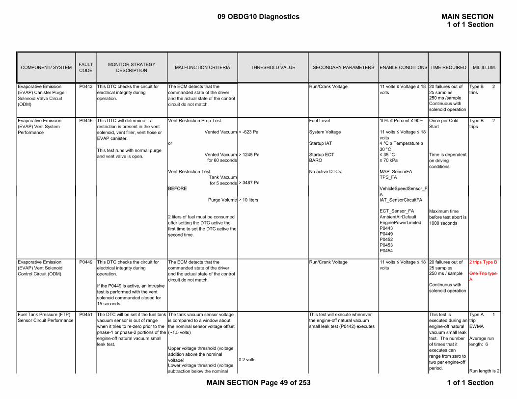
COMPONENT/ SYSTEM FAULT CODE
MONITOR STRATEGY DESCRIPTION MALFUNCTION CRITERIA THRESHOLD VALUE SECONDARY PARAMETERS ENABLE CONDITIONS TIME REQUIRED MIL ILLUM.
Run/Crank Voltage 11 volts ≤ Voltage ≤ 18 volts
20 failures out of 25 samples
Type B 2 trips
250 ms /sampleContinuous with solenoid operation
Vent Restriction Prep Test: Fuel Level 10% ≤ Percent ≤ 90% Type B 2 trips
Vented Vacuum < -623 Pa System Voltage 11 volts ≤ Voltage ≤ 18 volts
or Startup IAT 4 °C ≤ Temperature ≤ 30 °C
Vented Vacuum > 1245 Pa Startup ECT ≤ 35 °Cfor 60 seconds BARO ≥ 70 kPa
Vent Restriction Test: No active DTCs: MAP_SensorFATank Vacuumfor 5 seconds > 3487 Pa
TPS_FA
BEFORE V hi l S dS F
This DTC will determine if a restriction is present in the vent solenoid, vent filler, vent hose or EVAP canister.
This test runs with normal purge and vent valve is open.
Evaporative Emission (EVAP) Vent System Performance
P0446
Evaporative Emission (EVAP) Canister Purge Solenoid Valve Circuit (ODM)
The ECM detects that the commanded state of the driver and the actual state of the control circuit do not match.
P0443 This DTC checks the circuit for electrical integrity during operation.
Once per Cold Start
Time is dependent on driving conditions
BEFORE VehicleSpeedSensor_FA
Purge Volume ≥ 10 liters IAT_SensorCircuitFA
ECT_Sensor_FAAmbientAirDefaultEnginePowerLimitedP0443P0449P0452P0453P0454
Run/Crank Voltage 11 volts ≤ Voltage ≤ 18 volts
20 failures out of 25 samples
2 trips Type B
250 ms / sample One Trip type A
0.2 voltsLower voltage threshold (voltage subtraction below the nominal
P0449
P0451
2 liters of fuel must be consumed after setting the DTC active the first time to set the DTC active the second time.
The ECM detects that the commanded state of the driver and the actual state of the control circuit do not match.
This DTC checks the circuit for electrical integrity during operation.
If the P0449 is active, an intrusive test is performed with the vent solenoid commanded closed for 15 seconds.
Upper voltage threshold (voltage addition above the nominal voltage)
The tank vacuum sensor voltage is compared to a window about the nominal sensor voltage offset (~1.5 volts)
This test is executed during an engine-off natural vacuum small leak test. The number of times that it executes can range from zero to two per engine-off period.
Type A 1 trip EWMA
Average run length: 6
Run length is 2
The DTC will be set if the fuel tank vacuum sensor is out of range when it tries to re-zero prior to the phase-1 or phase-2 portions of the engine-off natural vacuum small leak test.
Evaporative Emission (EVAP) Vent Solenoid Control Circuit (ODM)
Fuel Tank Pressure (FTP) Sensor Circuit Performance
Continuous with solenoid operation
Maximum time before test abort is 1000 seconds
This test will execute whenever the engine-off natural vacuum small leak test (P0442) executes
09 OBDG10 Diagnostics MAIN SECTION1 of 1 Section
MAIN SECTION Page 49 of 253 1 of 1 Section

COMPONENT/ SYSTEM FAULT CODE
MONITOR STRATEGY DESCRIPTION MALFUNCTION CRITERIA THRESHOLD VALUE SECONDARY PARAMETERS ENABLE CONDITIONS TIME REQUIRED MIL ILLUM.
0.2 volts
When EWMA is > 0.73 (EWMA Fail Threshold)
the DTC light is illuminated.
voltage)
The difference between tank vacuum sensor voltage and the nominal offset voltage is then normalized against the appropriate threshold listed above to produce a ratio between 0.0 and 1.0. This normalized re-zero ratio is then filtered with a EWMA (with 0= perfect pass and 1=perfect fail).
The DTC light can be turned off if
trips after code clear or non-volatile reset
The length of the test is determined by the refueling rationality test, which can take up to 600 seconds to complete.
Fuel Tank Pressure (FTP) Sensor Circuit Low Voltage
This DTC will detect a fuel tank pressure sensor signal that is too low out of range.
Fuel tank pressure sensor signal < 0.15 volts (3 % of Vref or ~ 1681 Pa)
Time delay after sensor power up for sensor warm-up
is 0.10 seconds
80 failures out of 100 samples
Type B 2 trips
The normal operating range of the fuel tank pressure sensor is 0.5 volts (~1245 Pa) to 4.5 volts (~ -3736 Pa).
ECM State ≠ crank 100 ms / sample
ContinuousFuel tank pressure sensor signal > 4.85 volts (97% of Vref or ~ -
4172 Pa)Time delay after sensor power up for sensor warm-up
is 0.10 seconds
80 failures out of 100 samples
Type B 2 trips
The normal operating range of the fuel tank pressure sensor is 0.5 volts (~1245 Pa) to 4.5 volts (~ -3736 Pa).
ECM State ≠ crank 100 ms / sample
ContinuousType A 1 trip
If an abrupt change in tank vacuum is detected the engine-off natural vacuum test is aborted due to an apparent refueling event. Subsequent to the abort, a refueling rationality test is executed to confirm that a
Fuel Tank Pressure (FTP) Sensor Circuit Intermittent
P0452
P0453
This DTC will detect intermittent tank vacuum sensor signals that would have caused the engine-off natural vacuum small leak test to abort due to an apparent re-fueling event.
P0454
and stays below the EWMA fail threshold for 2 additional
consecutive trips.
This test is executed during an engine-off natural vacuum small leak test. The test can only execute up to once per engine-
The DTC light can be turned off if the EWMA is
≤ 0.40(EWMA Re-Pass Threshold)
This DTC will detect a fuel tank pressure sensor signal that is too high out of range.
Fuel Tank Pressure (FTP) Sensor Circuit High Voltage
This test will execute whenever the engine-off natural vacuum small leak test (P0442) executes
09 OBDG10 Diagnostics MAIN SECTION1 of 1 Section
MAIN SECTION Page 50 of 253 1 of 1 Section
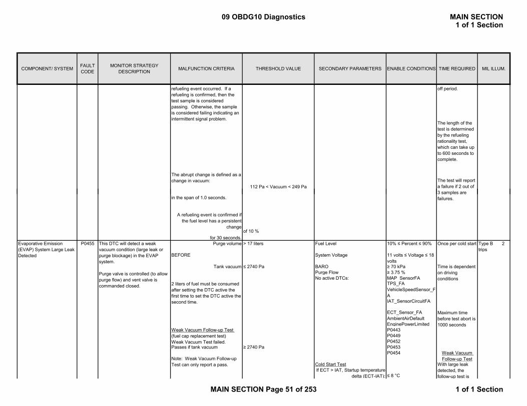
COMPONENT/ SYSTEM FAULT CODE
MONITOR STRATEGY DESCRIPTION MALFUNCTION CRITERIA THRESHOLD VALUE SECONDARY PARAMETERS ENABLE CONDITIONS TIME REQUIRED MIL ILLUM.
refueling event occurred. If a refueling is confirmed, then the test sample is considered passing. Otherwise, the sample is considered failing indicating an intermittent signal problem.
The abrupt change is defined as a change in vacuum:
off period.
112 Pa < Vacuum < 249 Pa
The length of the test is determined by the refueling rationality test, which can take up to 600 seconds to complete.
The test will report a failure if 2 out of
for 30 seconds.Purge volume > 17 liters Fuel Level 10% ≤ Percent ≤ 90% Type B 2
tripsBEFORE System Voltage 11 volts ≤ Voltage ≤ 18
volts Tank vacuum ≤ 2740 Pa BARO ≥ 70 kPa
Purge Flow ≥ 3.75 %No active DTCs: MAP_SensorFA
TPS_FAVehicleSpeedSensor_FAIAT_SensorCircuitFA
ECT_Sensor_FAAmbientAirDefaultEnginePowerLimitedP0443P0449P0452
Passes if tank vacuum ≥ 2740 Pa P0453P0454
Cold Start TestIf ECT > IAT, Startup temperature
delta (ECT-IAT): ≤ 8 °C
A refueling event is confirmed if the fuel level has a persistent
change
in the span of 1.0 seconds.
of 10 %
With large leak detected, the follow-up test is
2 liters of fuel must be consumed after setting the DTC active the first time to set the DTC active the second time.
Weak Vacuum Follow-up Test (fuel cap replacement test)Weak Vacuum Test failed.
Note: Weak Vacuum Follow-up Test can only report a pass.
P0455 This DTC will detect a weak vacuum condition (large leak or purge blockage) in the EVAP system.
Purge valve is controlled (to allow purge flow) and vent valve is commanded closed.
Evaporative Emission (EVAP) System Large Leak Detected
Time is dependent on driving conditions
Maximum time before test abort is 1000 seconds
Weak Vacuum Follow-up Test
Once per cold start
3 samples are failures.
09 OBDG10 Diagnostics MAIN SECTION1 of 1 Section
MAIN SECTION Page 51 of 253 1 of 1 Section

COMPONENT/ SYSTEM FAULT CODE
MONITOR STRATEGY DESCRIPTION MALFUNCTION CRITERIA THRESHOLD VALUE SECONDARY PARAMETERS ENABLE CONDITIONS TIME REQUIRED MIL ILLUM.
Cold Test Timer ≤ 1000 secondsStartup IAT Temperature 4 °C ≤ Temperature ≤
30 °CStartup ECT ≤ 35 °C
Weak Vacuum Follow-up TestThis test can run following a weak vacuum failure or on a hot restart.
Delta Fuel Volume change< 3 liters
Engine Running 250 ms / sample Type B 2 trips
over an accumulated 150 miles. No active DTCs: VehicleSpeedSensor_FA
Continuous
Fuel level Sender % of 5V range< 10 %
Run/Crank Voltage 11 volts ≤ Voltage ≤ 18 volts
180 failures out of 225 samples
Type B 2 trips
100 ms / sampleC ti
plimited to 1300 seconds. Once the MIL is on, the follow-up test runs
This DTC will detect a fuel sender stuck in range in the primary fuel tank.
Fuel Level Sensor 1 Circuit Low Voltage
This DTC will detect a fuel sender stuck out of range low in the primary fuel tank.
P0462
Fuel Level Sensor 1 Performance
P0461
ContinuousFuel level Sender % of 5V range
> 60 %Run/Crank Voltage 11 volts ≤ Voltage ≤ 18
volts 180 failures out of 225 samples
Type B 2 trips
100 ms / sampleContinuous
Type A 1 trip
An intermintant change in fuel level is defined as:The fuel level changes by 10 %and does not remain > 10 %
If a change in fuel level is detected, the engine-off natural vacuum test is aborted due to an apparent refueling event. Subsequent to the abort, a refueling rationality test is executed to confirm that an actual refueling event occurred. If a refueling event is confirmed, then the test sample is considered passing. Otherwise, the sample is considered failing indicating an intermittent signal problem.
The test will report a failure if 2 out of 3 samples are failures.
for 30 seconds during a 600 second refueling rationality test.
P0463
P0464
This DTC will detect a fuel sender stuck out ofrange high in the primary fuel tank.
Fuel Level Sensor 1 Circuit Intermittent
Fuel Level Sensor 1 Circuit High Voltage
This DTC will detect intermittent fuel level sensor signals that would have caused the engine-off natural vacuum small leak test to abort due to an apparent re-fueling event.
The length of the test is determined by the refueling rationality test, which can take up to 600 seconds to complete.
This test is executed during an engine-off natural vacuum small leak test. The test can only execute up to once per engine-off period.
This test will execute whenever the engine-off natural vacuum small leak test (P0442) executes
09 OBDG10 Diagnostics MAIN SECTION1 of 1 Section
MAIN SECTION Page 52 of 253 1 of 1 Section
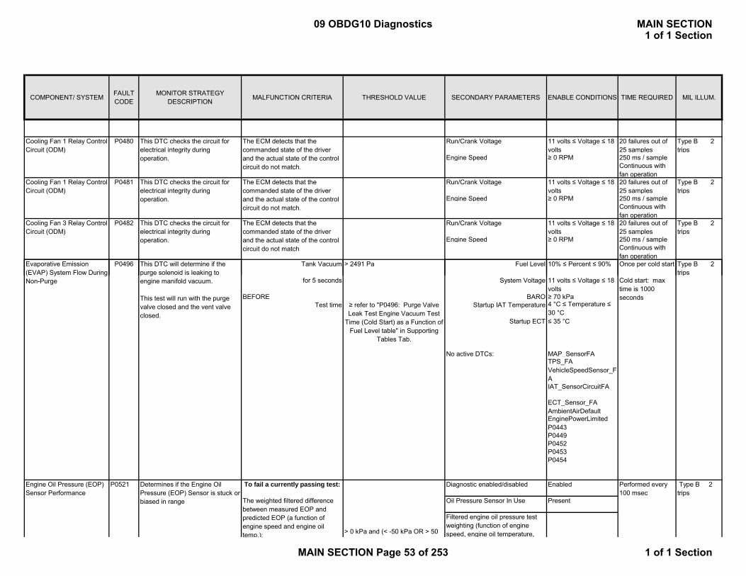
COMPONENT/ SYSTEM FAULT CODE
MONITOR STRATEGY DESCRIPTION MALFUNCTION CRITERIA THRESHOLD VALUE SECONDARY PARAMETERS ENABLE CONDITIONS TIME REQUIRED MIL ILLUM.
Run/Crank Voltage 11 volts ≤ Voltage ≤ 18 volts
20 failures out of 25 samples
Type B 2 trips
Engine Speed ≥ 0 RPM 250 ms / sampleContinuous with fan operation
Run/Crank Voltage 11 volts ≤ Voltage ≤ 18 volts
20 failures out of 25 samples
Type B 2 trips
Engine Speed ≥ 0 RPM 250 ms / sampleContinuous with fan operation
Run/Crank Voltage 11 volts ≤ Voltage ≤ 18 volts
20 failures out of 25 samples
Type B 2 trips
Engine Speed ≥ 0 RPM 250 ms / sampleContinuous with fan operation
Tank Vacuum > 2491 Pa Fuel Level 10% ≤ Percent ≤ 90% Once per cold start Type B 2 t i
The ECM detects that the commanded state of the driver and the actual state of the control circuit do not match.
The ECM detects that the commanded state of the driver and the actual state of the control circuit do not match.
Cooling Fan 1 Relay Control Circuit (ODM)
P0480 This DTC checks the circuit for electrical integrity during operation.
P0481 This DTC checks the circuit for electrical integrity during operation.
Cooling Fan 1 Relay Control Circuit (ODM)
Cooling Fan 3 Relay Control Circuit (ODM)
P0482 This DTC checks the circuit for electrical integrity during operation.
Evaporative Emission (EVAP) S t Fl D i
This DTC will determine if the l id i l ki t
P0496
The ECM detects that the commanded state of the driver and the actual state of the control circuit do not match
tripsfor 5 seconds System Voltage 11 volts ≤ Voltage ≤ 18
volts BEFORE BARO ≥ 70 kPa
Test time Startup IAT Temperature 4 °C ≤ Temperature ≤ 30 °C
Startup ECT ≤ 35 °C
No active DTCs: MAP_SensorFATPS_FAVehicleSpeedSensor_FAIAT_SensorCircuitFA
ECT_Sensor_FAAmbientAirDefaultEnginePowerLimitedP0443P0449P0452P0453P0454
> 0 kPa and (< -50 kPa OR > 50
Performed every 100 msec
Oil Pressure Sensor In Use Present
Filtered engine oil pressure test weighting (function of engine speed, engine oil temperature,
To fail a currently passing test:
The weighted filtered difference between measured EOP and predicted EOP (a function of engine speed and engine oil temp.):
(EVAP) System Flow During Non-Purge
purge solenoid is leaking to engine manifold vacuum.
This test will run with the purge valve closed and the vent valve closed.
Engine Oil Pressure (EOP) Sensor Performance
P0521 Determines if the Engine Oil Pressure (EOP) Sensor is stuck or biased in range
Diagnostic enabled/disabled Enabled
Cold start: max time is 1000 seconds
≥ refer to "P0496: Purge Valve Leak Test Engine Vacuum Test
Time (Cold Start) as a Function of Fuel Level table" in Supporting
Tables Tab.
Type B 2 trips
09 OBDG10 Diagnostics MAIN SECTION1 of 1 Section
MAIN SECTION Page 53 of 253 1 of 1 Section

COMPONENT/ SYSTEM FAULT CODE
MONITOR STRATEGY DESCRIPTION MALFUNCTION CRITERIA THRESHOLD VALUE SECONDARY PARAMETERS ENABLE CONDITIONS TIME REQUIRED MIL ILLUM.
No active DTC's Fault bundles:CrankSensorFAECT_Sensor_FAMAF_SensorFAIAT_SensorFAEOPCircuit_FA
Engine Running = True 50 failures out of
kPa)
(Engine Oil Pressure Sensor
> 0 kPa and (> -47 kPa AND < 47 kPa)
p g ppredicted oil pressure, and engine load stability). Details on Supporting Tables Tab (P0521 Section)
>= .3 ratio
p )
To pass a currently failing test:The weighted filtered difference between measured EOP and predicted EOP (a function of engine speed and engine oil temp.):
Engine Oil Pressure (EOP) P0522 Determines if the Engine Oil Type B 2Engine Running = True
< 5 percent Ignition Voltage <= 18.0 V and >= 11.0 Sensor Present No
Engine Running = True
> 85 percent Ignition Voltage <= 18.0 V and >= 11.0 Sensor Present No
P0601 Output state invalid PCM State = crank or run Type A1 trip
P0602 Output state invalid PCM State = crank or run Type A1 trip
50 failures out of 63 samples
(Engine Oil Pressure Sensor Circuit Voltage) / 5 Volts
(Engine Oil Pressure Sensor Circuit Voltage) / 5
Diagnostic reports a fault if 1 failure occurs on the first pass.
Diagnostic reports a fault if 5 failures occur after the first pass is complete.
Control Module Not Programmed
Engine Oil Pressure (EOP) Sensor Circuit Low Voltage
P0522 Determines if the Engine Oil Pressure (EOP) Sensor circuit voltage is too low
P0523 Determines if the Engine Oil Pressure (EOP) Sensor circuit voltage is too high
This DTC will be stored if the calibration check sum is incorrect
Engine Oil Pressure (EOP) Sensor Circuit High Voltage
Performed every 100 msecDiagnostic enabled/disabled
Control Module Read Only Memory (ROM)
This DTC will be stored if the PCM is a service PCM that has not been programmed.
204 failures out of 255 samples
Enabled
Diagnostic runs continuously in the background
Enabled
PCM is identified through calibration as a
Diagnostic runs at powerup
Performed every 100 msecDiagnostic enabled/disabled
Type B 2 trips
Type B 2 trips
09 OBDG10 Diagnostics MAIN SECTION1 of 1 Section
MAIN SECTION Page 54 of 253 1 of 1 Section

COMPONENT/ SYSTEM FAULT CODE
MONITOR STRATEGY DESCRIPTION MALFUNCTION CRITERIA THRESHOLD VALUE SECONDARY PARAMETERS ENABLE CONDITIONS TIME REQUIRED MIL ILLUM.
P0603Type A1 trip
ECM RAM Failure P0604 1. Primary processor data pattern written doesn’t match the pattern read for a count >
1 count if found on first memory scan. 5counts if found on subsequent scans.
1. Will finish first memory scan within 30 seconds at all engine conditions - diagnostic runs continuously
Type A1 trip
2. Secondary processor battery backed RAM failed checksum twice for original values at power up and the defaulted values
2. Completion at intilization, <500 ms
Non-volatile memory checksum error at controller power-up
Checksum at power-up does not match checksum at power-down
Indicates that the ECM is unable to correctly read data from or write data to RAM
Control Module Long Term Memory Reset
Diagnostic runs at powerup
Diagnostic reports a fault if 1 failure occurs
p
3. Secondary processor copy of calibration area to RAM failed for a count > 2counts
3. Completion at intilization, <500 ms
4. Secondary Processor data pattern written doesn’t match the pattern read consecutive times
4. Will finish within 30 seconds at all engine conditions.
5. Secondary Processor TPS or APPS minimum learned values fail compliment check continuously
5. 0.0625sec continuous
ECM Processor P0606 Type A1 trip
1.Communication of Seed & Key values between processors
Returned values from Seed & Key algorithm different than expected
Run/crank voltage or Powertrain relay voltage > 6.00 and reduced power is false, else the failure will be reported for all conditions
1. 3/17 counts; 50.0ms/count
No errors exist in intercommunication between primary and secondary processors
Indicates that the ECM has detected an internal processor integrity fault
09 OBDG10 Diagnostics MAIN SECTION1 of 1 Section
MAIN SECTION Page 55 of 253 1 of 1 Section
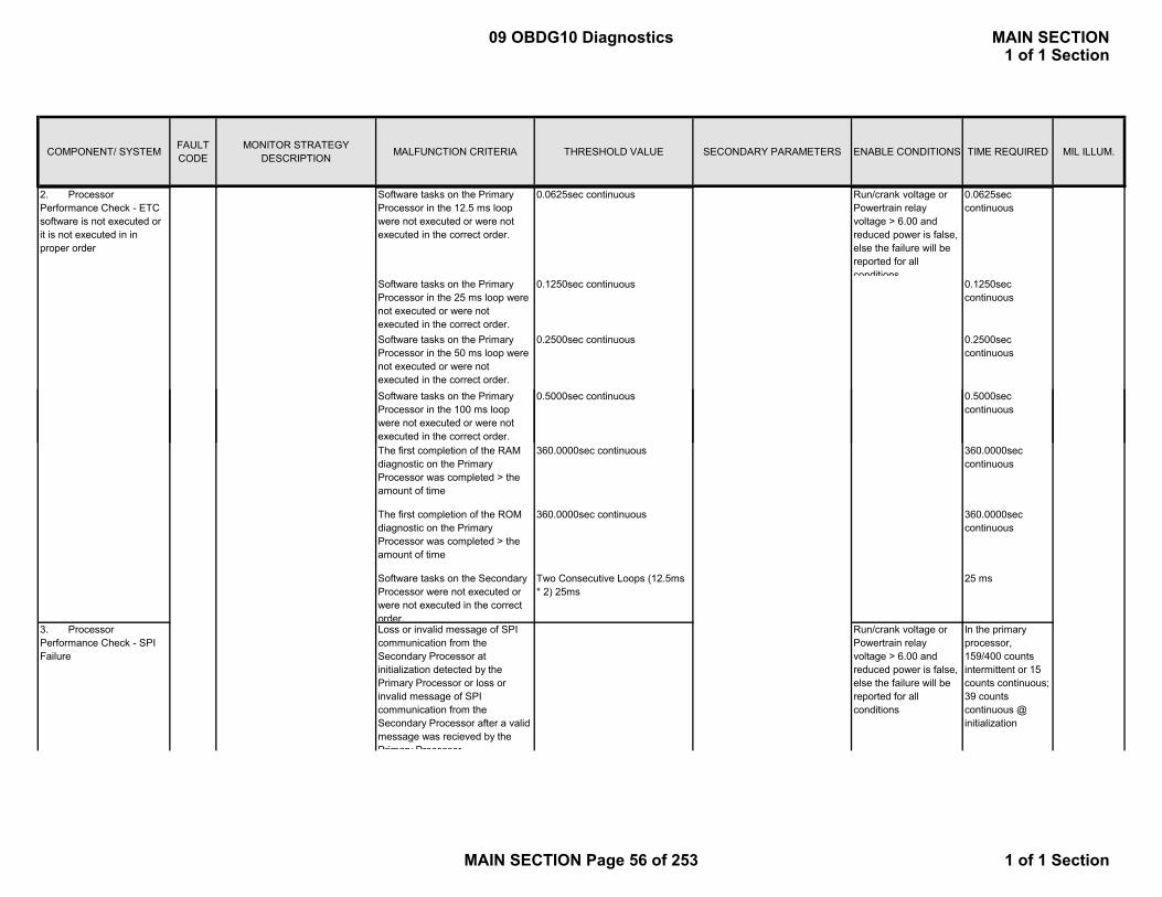
COMPONENT/ SYSTEM FAULT CODE
MONITOR STRATEGY DESCRIPTION MALFUNCTION CRITERIA THRESHOLD VALUE SECONDARY PARAMETERS ENABLE CONDITIONS TIME REQUIRED MIL ILLUM.
2. Processor Performance Check - ETC software is not executed or it is not executed in in proper order
Software tasks on the Primary Processor in the 12.5 ms loop were not executed or were not executed in the correct order.
0.0625sec continuous Run/crank voltage or Powertrain relay voltage > 6.00 and reduced power is false, else the failure will be reported for all conditions
0.0625sec continuous
Software tasks on the Primary Processor in the 25 ms loop were not executed or were not executed in the correct order.
0.1250sec continuous 0.1250sec continuous
Software tasks on the Primary Processor in the 50 ms loop were not executed or were not executed in the correct order.
0.2500sec continuous 0.2500sec continuous
Software tasks on the Primary Processor in the 100 ms loop were not executed or were not
0.5000sec continuous 0.5000sec continuous
were not executed or were not executed in the correct order.The first completion of the RAM diagnostic on the Primary Processor was completed > the amount of time
360.0000sec continuous 360.0000sec continuous
The first completion of the ROM diagnostic on the Primary Processor was completed > the amount of time
360.0000sec continuous 360.0000sec continuous
Software tasks on the Secondary Processor were not executed or were not executed in the correct order.
Two Consecutive Loops (12.5ms * 2) 25ms
25 ms
3. Processor Performance Check - SPI Failure
Loss or invalid message of SPI communication from the Secondary Processor at initialization detected by the Primary Processor or loss or invalid message of SPI communication from the Secondary Processor after a valid message was recieved by the Primary Processor
Run/crank voltage or Powertrain relay voltage > 6.00 and reduced power is false, else the failure will be reported for all conditions
In the primary processor, 159/400 counts intermittent or 15 counts continuous; 39 counts continuous @ initialization
09 OBDG10 Diagnostics MAIN SECTION1 of 1 Section
MAIN SECTION Page 56 of 253 1 of 1 Section

COMPONENT/ SYSTEM FAULT CODE
MONITOR STRATEGY DESCRIPTION MALFUNCTION CRITERIA THRESHOLD VALUE SECONDARY PARAMETERS ENABLE CONDITIONS TIME REQUIRED MIL ILLUM.
Loss or invalid message of SPI communication from the Primary Processor at initialization detected by the Secondary Processor or loss or invalid message of SPI communication from the Primary Processor after a valid message was recieved by the Secondary Processor
In the secondary processor 0.4750sec at initialization, 0.1750sec continuous or 20/200 intermittent.
4. Processor Performance Check - Secondary Processor state of health (Main)
Primary processor check of the secondary processor by verifing the hardware line toggle between the two processors toggles within the threshold values
9.3750sec and 15.6250sec Run/crank voltage or Powertrain relay voltage > 6.00 and reduced power is false, else the failure will be reported for all conditions
9counts continuous at initialization or 9 counts continuous; 12.5 msec /count in the Primary processor
P P i P TPS APPS R / k l 0 10005. Processor Performance Check - Primary Processor Learn Corruption Fault
Primary Processor TPS or APPS minimum learned values fail compliment check
Run/crank voltage or Powertrain relay voltage > 6.00 and reduced power is false, else the failure will be reported for all conditions
0.1000sec continuous
6. Processor Performance Check - Primary Processor Clock Fault
The ocillator failed for the Primary processor where the clock is outside the threshold
27.85 kHz and 37.68 kHz Run/crank voltage or Powertrain relay voltage > 6.00 and reduced power is false, else the failure will be reported for all conditions
100ms continuous
7. Processor Performance Check - Secondary Processor ALU Fault
The secondary check of the ALU failed to compute the expected result
Run/crank voltage or Powertrain relay voltage > 6.00 and reduced power is false, else the failure will be reported for all conditions
12.5ms continuous
8. Processor Performance Check - Secondary Processor Register Configuration Fault
Secondary processor failed configuration check of the registers.
Run/crank voltage or Powertrain relay voltage > 6.00 and reduced power is false, else the failure will be reported for all conditions
12.5ms continuous
09 OBDG10 Diagnostics MAIN SECTION1 of 1 Section
MAIN SECTION Page 57 of 253 1 of 1 Section
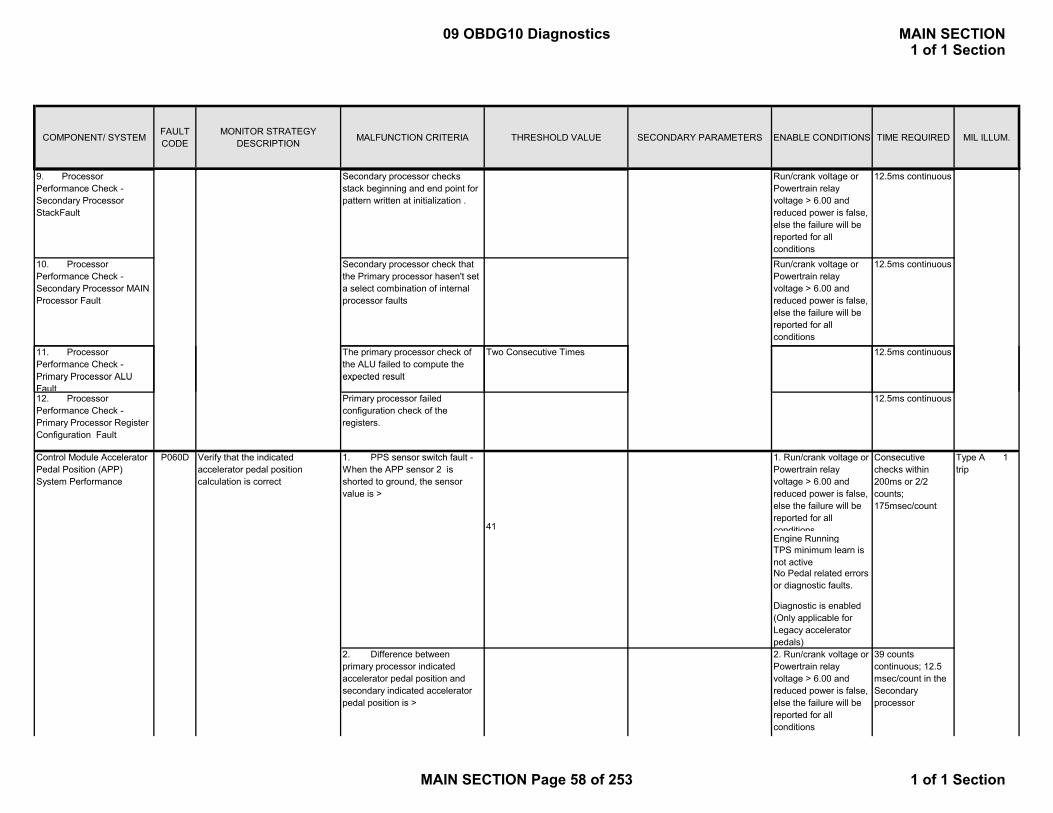
COMPONENT/ SYSTEM FAULT CODE
MONITOR STRATEGY DESCRIPTION MALFUNCTION CRITERIA THRESHOLD VALUE SECONDARY PARAMETERS ENABLE CONDITIONS TIME REQUIRED MIL ILLUM.
9. Processor Performance Check - Secondary Processor StackFault
Secondary processor checks stack beginning and end point for pattern written at initialization .
Run/crank voltage or Powertrain relay voltage > 6.00 and reduced power is false, else the failure will be reported for all conditions
12.5ms continuous
10. Processor Performance Check - Secondary Processor MAIN Processor Fault
Secondary processor check that the Primary processor hasen't set a select combination of internal processor faults
Run/crank voltage or Powertrain relay voltage > 6.00 and reduced power is false, else the failure will be reported for all conditions
12.5ms continuous
11. Processor Performance Check - Primary Processor ALU
The primary processor check of the ALU failed to compute the expected result
Two Consecutive Times 12.5ms continuous
Primary Processor ALU Fault
expected result
12. Processor Performance Check - Primary Processor Register Configuration Fault
Primary processor failed configuration check of the registers.
12.5ms continuous
P060D Verify that the indicated accelerator pedal position calculation is correct
41
1. Run/crank voltage or Powertrain relay voltage > 6.00 and reduced power is false, else the failure will be reported for all conditions
Consecutive checks within 200ms or 2/2 counts; 175msec/count
Type A 1 trip
Engine RunningTPS minimum learn is not activeNo Pedal related errors or diagnostic faults.
Diagnostic is enabled (Only applicable for Legacy accelerator pedals)2. Run/crank voltage or Powertrain relay voltage > 6.00 and reduced power is false, else the failure will be reported for all conditions
1. PPS sensor switch fault - When the APP sensor 2 is shorted to ground, the sensor value is >
Control Module Accelerator Pedal Position (APP) System Performance
39 counts continuous; 12.5 msec/count in the Secondary processor
2. Difference between primary processor indicated accelerator pedal position and secondary indicated accelerator pedal position is >
09 OBDG10 Diagnostics MAIN SECTION1 of 1 Section
MAIN SECTION Page 58 of 253 1 of 1 Section

COMPONENT/ SYSTEM FAULT CODE
MONITOR STRATEGY DESCRIPTION MALFUNCTION CRITERIA THRESHOLD VALUE SECONDARY PARAMETERS ENABLE CONDITIONS TIME REQUIRED MIL ILLUM.
Primary Processor Pedal Sync Error is FALSE
5Engine RunningTPS minimum learn is not active
Diagnostic is enabled (Only applicable for Legacy accelerator pedals)
1 test failure Type A1 trips
P0641 Primary Processor Vref1 < 4 432 Run/crank voltage or Type A19/39 counts or
Diagnostic runs once at powerup
Ignition State = unlock/accesory, run, or crank
Control Module EEPROM Error
P062F Indicates that the NVM Error flag has not been cleared
Detects a continuous or5 Volt Reference #1 Circuit
Last EEPROM write did not complete
P0641 Primary Processor Vref1 < 4.432 Run/crank voltage or Powertrain relay voltage > 6.00 and reduced power is false, else the failure will be reported for all conditions
Type A1 trips
Primary Processor Vref1 > 4.659
Secondary Processor Vref1 < 4.432
Secondary Processor Vref1 > 4.659
Run/Crank Voltage 11 volts ≤ Voltage ≤ 18 volts
20 failures out of 25 samples
Type B 2 trips
Remote Vehicle Start is not active 250 ms / sample NO MIL
ContinuousP0651 Primary Processor Vref2 < 4.432 Run/crank voltage or
Powertrain relay voltage > 6.00 and reduced power is false, else the failure will be reported for all conditions
19/39 counts or 0.1875sec continuous; 12.5 msec/count in main /Secondary processor
Type A 1 trip
or Primary Processor Vref2 > 4.659
Secondary Processor Vref1 < 4.432
Secondary Processor Vref1 > 4.659
19/39 counts or 0.1875sec continuous; 12.5 msec/count in Primary processor
The ECM detects that the commanded state of the driver and the actual state of the control circuit do not match.
19/39 counts or 15 counts continuous; 12.5 msec/count in Secondary processor
19/39 counts or 15 counts continuous; 12.5 msec/count in Secondary processor
5 Volt Reference #2 Circuit
Detects a continuous or intermittent short on th 5 volt reference circuit #1
Detects a continuous or intermittent short on th 5 volt reference circuit #2
This DTC checks the circuit for electrical integrity during operation.
5 Volt Reference #1 Circuit
Malfunction Indicator Lamp (MIL) Control Circuit (ODM)
P0650
09 OBDG10 Diagnostics MAIN SECTION1 of 1 Section
MAIN SECTION Page 59 of 253 1 of 1 Section
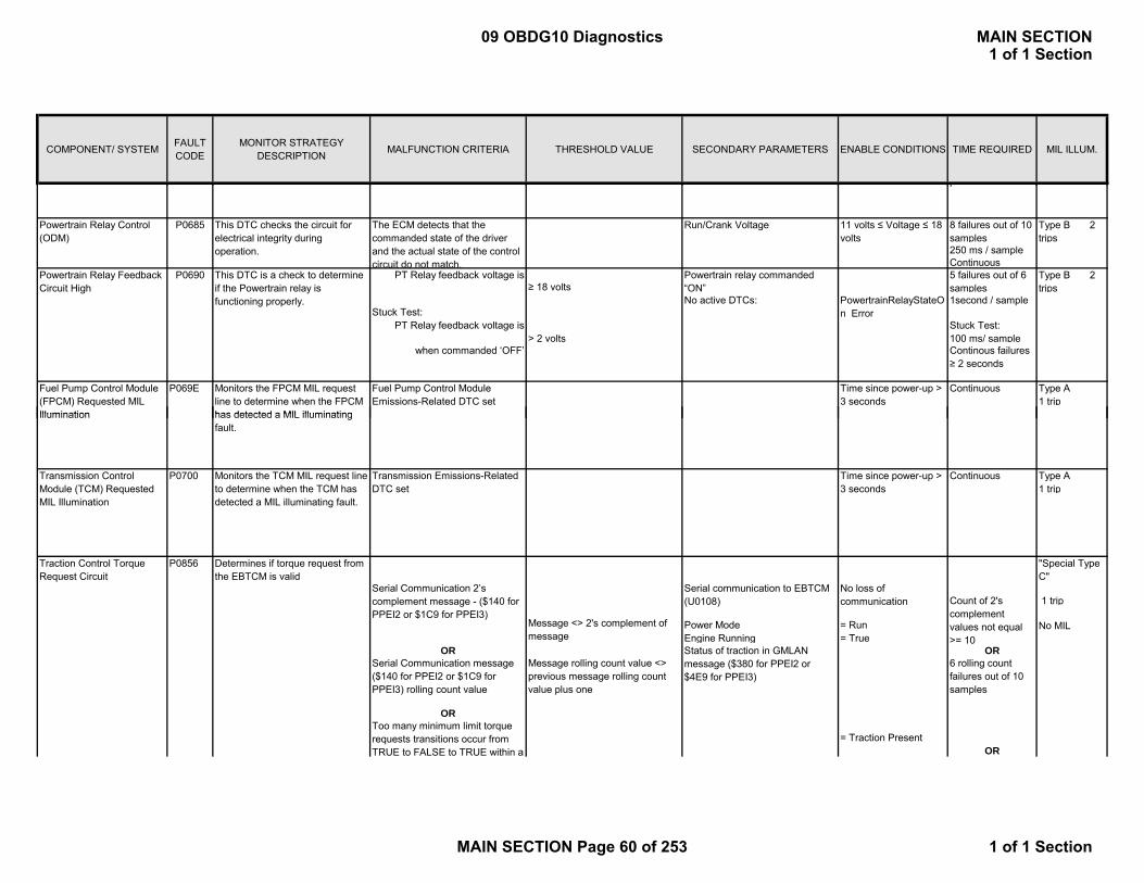
COMPONENT/ SYSTEM FAULT CODE
MONITOR STRATEGY DESCRIPTION MALFUNCTION CRITERIA THRESHOLD VALUE SECONDARY PARAMETERS ENABLE CONDITIONS TIME REQUIRED MIL ILLUM.
Run/Crank Voltage 11 volts ≤ Voltage ≤ 18 volts
8 failures out of 10 samples
Type B 2 trips
250 ms / sampleContinuous
PT Relay feedback voltage is ≥ 18 volts
Powertrain relay commanded “ON”
5 failures out of 6 samples
Type B 2 trips
Stuck Test:No active DTCs: PowertrainRelayStateO
n Error1second / sample
PT Relay feedback voltage is > 2 volts
Stuck Test:100 ms/ sample
when commanded ‘OFF’ Continous failures ≥ 2 seconds
Type A1 trip
Fuel Pump Control Module (FPCM) Requested MIL Illumination
P069E
This DTC is a check to determine if the Powertrain relay is functioning properly.
p
Continuous
Powertrain Relay Feedback Circuit High
P0690
Monitors the FPCM MIL request line to determine when the FPCM has detected a MIL illuminating
Time since power-up > 3 seconds
Powertrain Relay Control(ODM)
P0685 This DTC checks the circuit for electrical integrity during operation.
Fuel Pump Control Module Emissions-Related DTC set
The ECM detects that the commanded state of the driver and the actual state of the control circuit do not match.
Type A1 trip
1 trip
Power Mode = Run No MILEngine Running = True
OR ORSerial Communication message ($140 for PPEI2 or $1C9 for PPEI3) rolling count value
OR
OR
"Special Type C"
P0700 Monitors the TCM MIL request line to determine when the TCM has detected a MIL illuminating fault.
Illumination
Transmission Control Module (TCM) Requested MIL Illumination
P0856
Serial communication to EBTCM (U0108)
Status of traction in GMLAN message ($380 for PPEI2 or $4E9 for PPEI3)
Continuous
has detected a MIL illuminating fault.
Time since power-up > 3 seconds
= Traction Present
No loss of communication
Traction Control Torque Request Circuit
Determines if torque request from the EBTCM is valid
Count of 2's complement values not equal >= 10
6 rolling count failures out of 10 samples
Message rolling count value <> previous message rolling count value plus one
Serial Communication 2’s complement message - ($140 for PPEI2 or $1C9 for PPEI3)
Transmission Emissions-Related DTC set
Message <> 2's complement of message
Too many minimum limit torque requests transitions occur from TRUE to FALSE to TRUE within a
09 OBDG10 Diagnostics MAIN SECTION1 of 1 Section
MAIN SECTION Page 60 of 253 1 of 1 Section

COMPONENT/ SYSTEM FAULT CODE
MONITOR STRATEGY DESCRIPTION MALFUNCTION CRITERIA THRESHOLD VALUE SECONDARY PARAMETERS ENABLE CONDITIONS TIME REQUIRED MIL ILLUM.
3. # of Multi Transition errors >= 3, and Traction Torque Request >= Driver + 2088 Nm
Performed every 25 msec
Cold Start Fail: Delta between powerup PECL temp and coolant temp
> 30° C Engine off time > 36000 seconds Once at powerup (12.5ms frequency)
500msAnd
No Active DTC'sP0112, P0113, P0117,P0118, P0101, P0102P0103 P0A02 P0A03
Determines the Range/Performance of the PECL
P0A01Motor Electronics Coolant Temperature Sensor Circuit Range/Performance
Type B2 trips
time period, with a torque request value greater than or equal to the driver’s axle torque request plus the torque security acceleration threshold
P0103, P0A02, P0A03,P2610
Delta between powerup ECT and IAT
<= 15.75 ° C
Cold Start Pass:
Delta between powerup PECL temp and coolant temp
<= 15.75 ° C
&Delta Between powerup ECT and IAT
<= 15.75 ° C
Motor Electronics Coolant Temperature
> 162° C No Active DTC's IAT_SensorCircuitFA 100 ms 3 seconds
Minimum IAT
< 70° C 30 fail out of 50 samples; 100ms frequency
And Propulsion active time > 10 Seconds
Delta between powerup ECT and IAT
<= 15.75 ° C
Engine off time > 28800 seconds Continuous
Motor Electronics Coolant Temperature
< -60.5° C No Active DTC's P0112, P0113 3 seconds
Minimum IAT
< -20° C 30 fail out of 50 samples; 100ms frequency
Determines the PECL Out of range high
Motor Electronics Coolant Temperature Sensor Circuit Low
P0A02 Type B2 trips
Type B2 trips
Determines the PECL Out of range low
Motor Electronics Coolant Temperature Sensor Circuit High
P0A03
09 OBDG10 Diagnostics MAIN SECTION1 of 1 Section
MAIN SECTION Page 61 of 253 1 of 1 Section

COMPONENT/ SYSTEM FAULT CODE
MONITOR STRATEGY DESCRIPTION MALFUNCTION CRITERIA THRESHOLD VALUE SECONDARY PARAMETERS ENABLE CONDITIONS TIME REQUIRED MIL ILLUM.
And Propulsion active time > 10 Seconds
Delta between powerup ECT and IAT
<= 15.75 ° C
Engine off time > 28800 seconds Continuous
Hybrid Prowtrain Control Module
P0A1D Indicates that the MCPA has detected an HCP Status Failure fault
ECM criteria to look for MCPA message
Run/Crank High for at least 2.5000sec
3/4 counts; 12.5ms/count
Type A 1 trip 2 Trip Type B
All other parameters and enable conditions are controlled by the PLD and MCPA processors in the HCP.
Type A 1 trip
Filtered Throttle Model <= 150 kPa/(g/s) Engine Speed >= 450 RPMEngine Speed <= 8000 RPM
AND Coolant Temp > -7 Deg CCoolant Temp < 125 Deg CIntake Air Temp > -7 Deg CIntake Air Temp < 125 Deg C
OR
AND
Continuous100 msec
Determines if there are multiple air induction problems affecting airflow and/or manifold pressure.
P0AC4
Continuous
Calculation are performed every 12.5 msec
Minimum total weight factor (all factors multiplied together)
Hybrid Prowertrain Control Module Request MIL Illumination
< 0.00
Type B2 trips
Filtered Throttle Model multiplied by TPS Residual Weight Factor based on RPM
Inlet Airflow System Performance (naturally aspirated applications)
P1101
> 15.0 kPa )
> 10 grams/sec
Modeled Air Flow multiplied by MAF
> 15.0 kPa
ABS(Measured MAP – MAP Model 2) Filtered
Monitor Hybrid Control Module (HCP) MIL Request to determine when the HCP has detected a MIL illuminating fault.
Time since power-up > 3 seconds Time Since Code Clear > 2 secondsDiagnostic System not Disabled for ServiceRun Crank Active
ABS(Measured MAP – MAP Model 1) Filtered
HCP Emissions-Related DTC set
( ABS(Measured Flow – Modeled Air Flow) Filtered
09 OBDG10 Diagnostics MAIN SECTION1 of 1 Section
MAIN SECTION Page 62 of 253 1 of 1 Section

COMPONENT/ SYSTEM FAULT CODE
MONITOR STRATEGY DESCRIPTION MALFUNCTION CRITERIA THRESHOLD VALUE SECONDARY PARAMETERS ENABLE CONDITIONS TIME REQUIRED MIL ILLUM.
MAP Model 1 multiplied by MAP1 Residual Weight Factor based on RPM
MAP Model 2 multiplied by MAP2 Residual Weight Factor based on RPM
Residual Weight Factor based on RPM and MAF Residual Weight Factor Based on MAF Estimate
No Active DTCs:MAP_SensorCircuitFAEGRValve_FPEGRValvePerformance_FA
MAF_SensorCircuitFACrankSensorFAECT_sensor_FAECT_Sensor_FPIAT_SensorFAIAT_SensorCircuitFP
CylDeacSystemTFTKO
No Active DTC's TPS_ThrottleAuthorityDefaultedMAP_SensorFAIAT_SensorFAECT_Sensor_FAAmbientAirDefaultMAF_SensorFAEvapPurgeSolenoidCircuit_FAEvapFlowDuringNonPurge_FA
This DTC determines if the O2 sensor is no longer sufficiently switching.
O2S Insufficient Switching Bank 1 Sensor 1
P1133 Type B 2 trips
Frequency:Once per trip
Green Sensor Delay Criteria
Sample time is 40 seconds
See table "IFRD Residual Weighting Factors".
Fault condition present if Half Cycle L/R or R/L Switches are below the threshold.
OR
If Slope Time L/R or R/L Switches are below the threshold.
H/C L/R switches < Threshold, or H/C R/L switches < Threshold, (refer to table named "P1133 - O2S HC L to R Switches Limit Bank 1 Sensor 1" Pass/Fail Threshold table & "P1133 - O2S HC R to L Switches Limit Bank 1 Sensor 1" Pass/Fail Threshold table in Supporting tables tab)
OR
09 OBDG10 Diagnostics MAIN SECTION1 of 1 Section
MAIN SECTION Page 63 of 253 1 of 1 Section

COMPONENT/ SYSTEM FAULT CODE
MONITOR STRATEGY DESCRIPTION MALFUNCTION CRITERIA THRESHOLD VALUE SECONDARY PARAMETERS ENABLE CONDITIONS TIME REQUIRED MIL ILLUM.
EvapVentSolenoidCircuit_FAEvapSmallLeak_FAEvapEmissionSystem_FAFuelTankPressureSnsrCkt_FA
FuelInjectorCircuit_FAAIR System FAEthanolCompositionSensor_FAEngineMisfireDetected_FA
Bank 1 Sensor 1 DTC's not active10.0 volts < system voltage< 18.0 volts
= P0131, P0132 or P0134
System Voltage
The diagnostic will not be enabled until the next ignition cycle after the following has been met: Airflow greater than 22 gps for 120000 grams of accumulated flow non-continuously. (Note that all other enable criteria must be met on the next ignition cycle for the test to run on that ignition cycle)
OR
S/T L/R switches < 1, or S/T R/L switches < 1
Idle Device Control = Not activeFuel Device Control = Not activeAIR Device Control = Not active
O2 Heater on for >= 0 seconds
Engine Coolant > 55 ºCIAT > -40 ºC
Engine run Accum > 160 secondsPurge duty cycle >= 0 % duty cycle
Engine speed 1000 <= RPM <= 3000Fuel < 87 % EthanolBaro > 70 kpa
Air Per Cylinder >= 150 mGrams
Fuel Control State = Closed LoopClosed Loop Active = TRUE
LTM fuel cell = Enabled
Baro = Not Defaulted
Fuel Control Statenot = Power Enrichment
= False
= Valid
Engine airflow
Low Fuel Condition Diag = False
= Not Valid
20 gps <= engine airflow <= 55 gps
Learned Htr resistance
Green O2S Condition
EGR Device Control = Not active
<= 100.0 mgrams
cycle).Note: This feature is only enabled when the vehicle is new and cannot be enabled in service
Transient Fuel Mass
Low Fuel Condition Diag
09 OBDG10 Diagnostics MAIN SECTION1 of 1 Section
MAIN SECTION Page 64 of 253 1 of 1 Section

COMPONENT/ SYSTEM FAULT CODE
MONITOR STRATEGY DESCRIPTION MALFUNCTION CRITERIA THRESHOLD VALUE SECONDARY PARAMETERS ENABLE CONDITIONS TIME REQUIRED MIL ILLUM.
Fuel State DFCO not active
Time > 4.5 seconds
No Active DTC's TPS_ThrottleAuthorityDefaultedMAP_SensorFAIAT_SensorFAECT_Sensor_FAAmbientAirDefaultMAF_SensorFAEvapPurgeSolenoidCircuit_FAEvapFlowDuringNonPurge_FAE V tS l idCi
Green Sensor Delay Criteria
Th di ti ill
This DTC determines if the O2 sensor is no longer sufficiently switching.
Fault condition present if Half Cycle L/R or R/L Switches are below the threshold.
OR
If Slope Time L/R or R/L Switches are below the threshold.
Commanded Proportional Gain >= 0.0 %
All of the above met for
Frequency:Once per trip
Type B 2 trips
Sample time is 40 seconds
O2S Insufficient Switching Bank 2 Sensor 1
P1153 H/C L/R switches < Threshold, or H/C R/L switches < Threshold, (refer to table named "P1153 - O2S HC L to R Switches Limit Bank 2 Sensor 1" Pass/Fail Threshold table & "P1153 - O2S HC R to L Switches Limit Bank 2 Sensor 1" Pass/Fail Threshold table in Supporting tables tab)
OR EvapVentSolenoidCircuit_FAEvapSmallLeak_FAEvapEmissionSystem_FAFuelTankPressureSnsrCkt_FA
FuelInjectorCircuit_FAAIR System FAEthanolCompositionSensor_FAEngineMisfireDetected_FA
Idle Device Control = Not activeFuel Device Control = Not activeAIR Device Control = Not active
O2 Heater on for >= 0 seconds
Engine Coolant > 55 ºCIAT > -40 ºC
Engine run Accum > 160 seconds
= False
The diagnostic will not be enabled until the next ignition cycle after the following has been met: Airflow greater than 22 gps for 120000 grams of accumulated flow non-continuously. (Note that all other enable criteria must be met on the next ignition cycle for the test to run on that ignition cycle).Note: This feature is only enabled when the vehicle is new and cannot be enabled in service
Bank 2 Sensor 1 DTC's not active
System Voltage
Green O2S Condition
Learned Htr resistance
= P0151, P0152 or P0154
= Valid
EGR Device Control
Low Fuel Condition Diag
10.0 volts < system voltage< 18.0 volts
= Not active
= Not Valid
OR
S/T L/R switches < 1, or S/T R/L switches < 1
09 OBDG10 Diagnostics MAIN SECTION1 of 1 Section
MAIN SECTION Page 65 of 253 1 of 1 Section
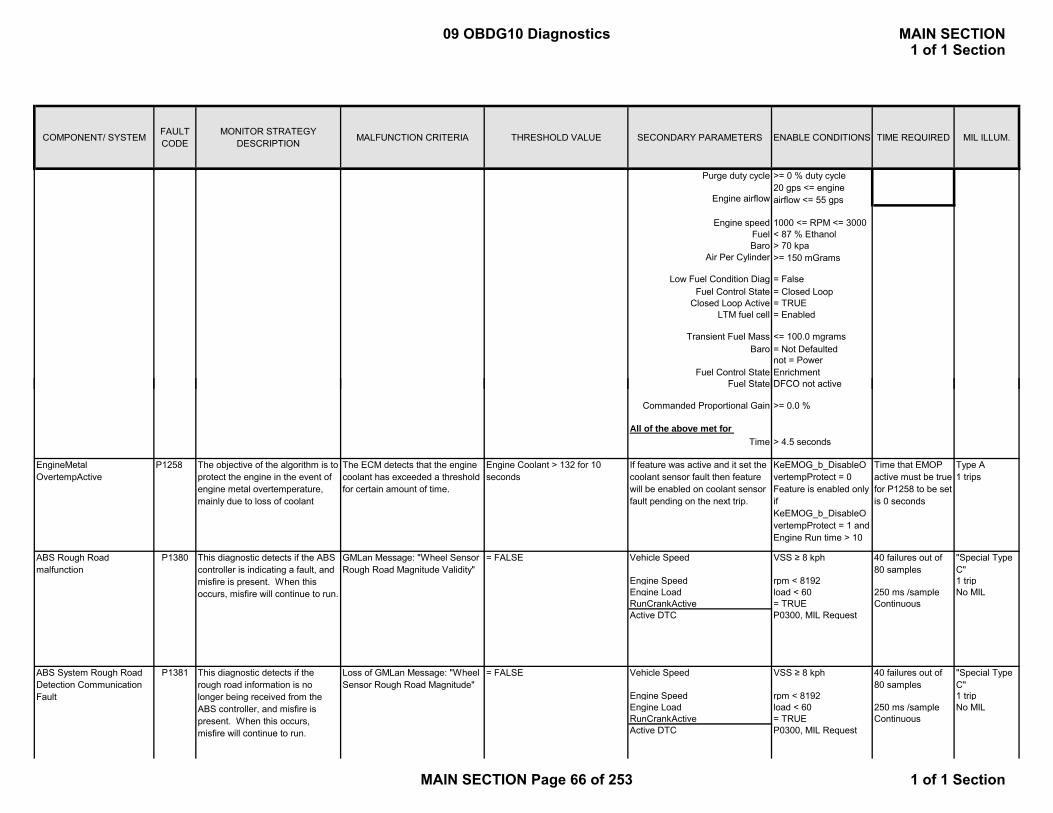
COMPONENT/ SYSTEM FAULT CODE
MONITOR STRATEGY DESCRIPTION MALFUNCTION CRITERIA THRESHOLD VALUE SECONDARY PARAMETERS ENABLE CONDITIONS TIME REQUIRED MIL ILLUM.
Purge duty cycle >= 0 % duty cycle
Engine speed 1000 <= RPM <= 3000Fuel < 87 % EthanolBaro > 70 kpa
Air Per Cylinder >= 150 mGrams
Fuel Control State = Closed LoopClosed Loop Active = TRUE
LTM fuel cell = Enabled
Baro = Not Defaulted
Fuel Control Statenot = Power Enrichment
F l St t DFCO t ti
Transient Fuel Mass <= 100.0 mgrams
Low Fuel Condition Diag = False
20 gps <= engine airflow <= 55 gpsEngine airflow
Fuel State DFCO not active
Time > 4.5 seconds
EngineMetalOvertempActive
P1258 The objective of the algorithm is to protect the engine in the event of engine metal overtemperature, mainly due to loss of coolant
The ECM detects that the engine coolant has exceeded a threshold for certain amount of time.
Engine Coolant > 132 for 10 seconds
If feature was active and it set the coolant sensor fault then feature will be enabled on coolant sensor fault pending on the next trip.
KeEMOG_b_DisableOvertempProtect = 0Feature is enabled only if KeEMOG_b_DisableOvertempProtect = 1 and Engine Run time > 10
Time that EMOP active must be true for P1258 to be set is 0 seconds
Type A1 trips
= FALSE Vehicle Speed VSS ≥ 8 kph "Special Type C"
Engine Speed rpm < 8192 1 tripEngine Load load < 60 250 ms /sample No MILRunCrankActive = TRUE ContinuousActive DTC P0300, MIL Request
= FALSE Vehicle Speed VSS ≥ 8 kph "Special Type C"
Engine Speed rpm < 8192 1 tripEngine Load load < 60 250 ms /sample No MILRunCrankActive = TRUE ContinuousActive DTC P0300, MIL Request
This diagnostic detects if the rough road information is no longer being received from the ABS controller, and misfire is present. When this occurs, misfire will continue to run.
This diagnostic detects if the ABS controller is indicating a fault, and misfire is present. When this occurs, misfire will continue to run.
ABS System Rough Road Detection Communication Fault
P1381
Commanded Proportional Gain
All of the above met for
GMLan Message: "Wheel Sensor Rough Road Magnitude Validity"
>= 0.0 %
ABS Rough Road malfunction
P1380 40 failures out of 80 samples
40 failures out of 80 samples
Loss of GMLan Message: "Wheel Sensor Rough Road Magnitude"
09 OBDG10 Diagnostics MAIN SECTION1 of 1 Section
MAIN SECTION Page 66 of 253 1 of 1 Section
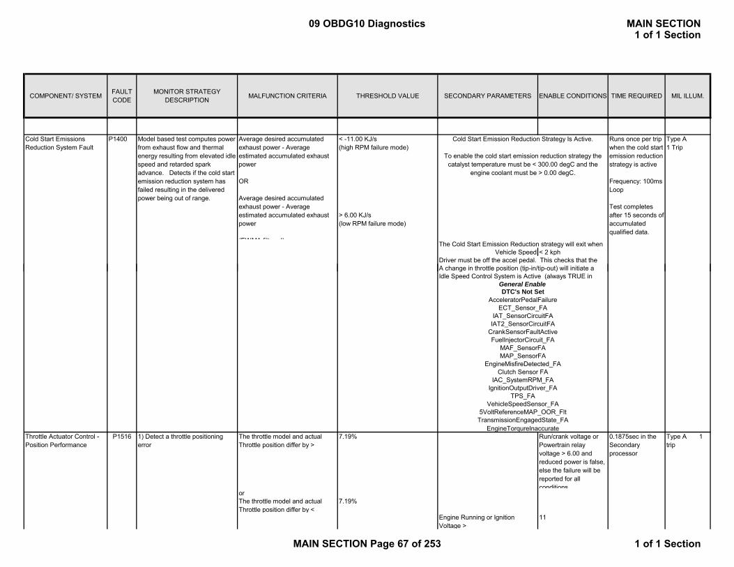
COMPONENT/ SYSTEM FAULT CODE
MONITOR STRATEGY DESCRIPTION MALFUNCTION CRITERIA THRESHOLD VALUE SECONDARY PARAMETERS ENABLE CONDITIONS TIME REQUIRED MIL ILLUM.
Model based test computes power from exhaust flow and thermal energy resulting from elevated idle speed and retarded spark advance. Detects if the cold start emission reduction system has failed resulting in the delivered power being out of range.
Average desired accumulated exhaust power - Average estimated accumulated exhaust power
OR
Average desired accumulated exhaust power - Average estimated accumulated exhaust power
(EWMA filtered)
< -11.00 KJ/s(high RPM failure mode)
> 6.00 KJ/s(low RPM failure mode)
Runs once per trip when the cold start emission reduction strategy is active
Frequency: 100ms Loop
Test completes after 15 seconds of accumulated qualified data.
Type A1 Trip
Vehicle Speed < 2 kph
Cold Start Emission Reduction Strategy Is Active.
To enable the cold start emission reduction strategy the catalyst temperature must be < 300.00 degC and the
engine coolant must be > 0.00 degC.
P1400Cold Start Emissions Reduction System Fault
The Cold Start Emission Reduction strategy will exit when
Driver must be off the accel pedal. This checks that the A h i th ttl iti (ti i /ti t) ill i iti t
P1516 The throttle model and actual Throttle position differ by >
7.19% Run/crank voltage or Powertrain relay voltage > 6.00 and reduced power is false, else the failure will be reported for all conditions
0.1875sec in the Secondary processor
Type A 1 trip
orThe throttle model and actual Throttle position differ by <
7.19%
Engine Running or Ignition Voltage >
11
ECT_Sensor_FA
Idle Speed Control System is Active (always TRUE in
DTC's Not Set
A change in throttle position (tip-in/tip-out) will initiate a
Clutch Sensor FA
IAT_SensorCircuitFAIAT2_SensorCircuitFA
MAF_SensorFAMAP_SensorFA
EngineMisfireDetected_FA
AcceleratorPedalFailure
Throttle Actuator Control - Position Performance
1) Detect a throttle positioning error
IgnitionOutputDriver_FATPS_FA
TransmissionEngagedState_FAEngineTorqureInaccurate
5VoltReferenceMAP_OOR_Flt
FuelInjectorCircuit_FA
VehicleSpeedSensor_FA
CrankSensorFaultActive
General Enable
IAC_SystemRPM_FA
09 OBDG10 Diagnostics MAIN SECTION1 of 1 Section
MAIN SECTION Page 67 of 253 1 of 1 Section

COMPONENT/ SYSTEM FAULT CODE
MONITOR STRATEGY DESCRIPTION MALFUNCTION CRITERIA THRESHOLD VALUE SECONDARY PARAMETERS ENABLE CONDITIONS TIME REQUIRED MIL ILLUM.
and Ignition Voltage > 5.4and Throttle is being Controlled
and Communication Fault (SPI is not set)and TPS minimum learn is not activeIgnition voltage failure is false (P1682)
2) Detect throttle control is driving the throttle in the incorrect direction
Thottle Position > 39.76% Run/crank voltage or Powertrain relay voltage > 6.00 and reduced power is false, else the failure will be reported for all conditions
0.1375sec continuous
(Throttle is being Controlled and
TPS minimum learn is active) or
Reduce Engine Power is Active
3) Degraded Motor Engine Running or Ignition Voltage >
11 0.4875sec continuous on secondary processor
and Ignition Voltage > 5.4and Throttle is being Controlled
and Communication Fault (SPI is not set)and TPS minimum learn is not activeIgnition voltage failure is false (P1682)
OR ORRun Crank Active >= 500 msec
Desired throttle position is stable within 0.25% for 4.0000sec and
the delta between Indicated throttle position and desired
throttle position is greater than 2.00%
Hybrid Control Torque Request Circuit
P15F2
. # of Alive Rolling Errors >= 10 out of 16 samples
No Serial communication loss to HCP (U1817)
Determines if torque request from the HCP is valid
1. Serial Communication 2’s complement not equal for message $0A9
2. Serial Communication rolling count value shall be + 1 from previous $0A9 message
1. # of Protect Errors >= 10out of 16 samples
Secondary High Speed Bus is Present
Message rolling count value <> previous message rolling count value plus one
Message <> 2's complement of message
Type A 1 trip
09 OBDG10 Diagnostics MAIN SECTION1 of 1 Section
MAIN SECTION Page 68 of 253 1 of 1 Section

COMPONENT/ SYSTEM FAULT CODE
MONITOR STRATEGY DESCRIPTION MALFUNCTION CRITERIA THRESHOLD VALUE SECONDARY PARAMETERS ENABLE CONDITIONS TIME REQUIRED MIL ILLUM.
Pass diagnostic if samples >= 16
Ignition Voltage Correlation P1682 |Run/Crank – ETC Run/Crank| > 3.00Volts Powertrain commanded on and 240/480 counts 12.5 msec/count in main processor or 0.175 sec when
ETC Run/Crank is lower than
Run/Crank by the threshold value
continuous;
Detect a continuous or intermittent out of correlation between the Run/Crank Ignition Voltage & the Powertrain Relay Ignition Voltage
Performed every 12.5 msec
Type A 1 trip
Run/crank voltage > Table, f(IAT). See supporting tables
or ETC Run/crank voltage > 5.5and Run/crank voltage > 5.5
Internal Control Module Redundant Memory Performance
P16F3 Detect Processor Calculation faults due to RAM corruptions, ALU failures and ROM failures
Desired engine torque request greater than redundant calculation plus threshold
61.77Nm Ignition in unlock/accessory, run or crank
4/8 counts; 25.0msec/count
Cylinders active greater than commanded
1 cylinder Engine speed greater than 0rpm and less than 3200rpm
6/8 counts; each cylinder firing event/count
Engine min capacity above threshold
61.77Nm Ignition in unlock/accessory, run or crank
3/4 counts; 12.5msec/count
No fast unmanaged retarded spark above the applied spark plus the threshold
Table, f(Erpm). See supporting tables
LoRes if engine rpm < 4500/4700rpm (hysteresis pair)6.25ms if engine rpm >= 4500/4700rpm (hysteresis pair)
6/8 counts; each cylinder firing event/count
Absolute difference of adjustment factor based on temperature and its dual store above threshold
3.99m/s Ignition in unlock/accessory, run or crank
2/4 counts; 100.0msec/count
Type A 1 trip
09 OBDG10 Diagnostics MAIN SECTION1 of 1 Section
MAIN SECTION Page 69 of 253 1 of 1 Section
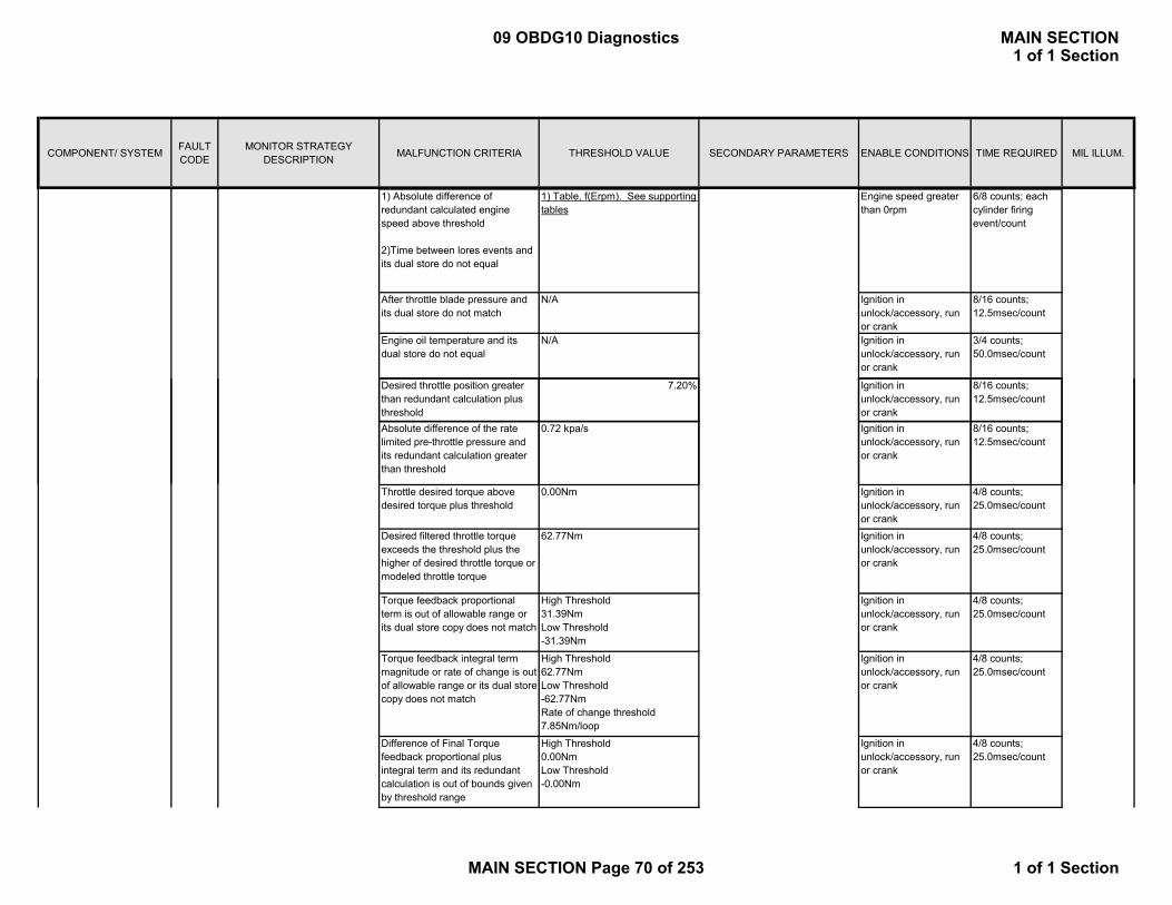
COMPONENT/ SYSTEM FAULT CODE
MONITOR STRATEGY DESCRIPTION MALFUNCTION CRITERIA THRESHOLD VALUE SECONDARY PARAMETERS ENABLE CONDITIONS TIME REQUIRED MIL ILLUM.
1) Absolute difference of redundant calculated engine speed above threshold
2)Time between lores events and its dual store do not equal
1) Table, f(Erpm). See supporting tables
Engine speed greater than 0rpm
6/8 counts; each cylinder firing event/count
After throttle blade pressure and its dual store do not match
N/A Ignition in unlock/accessory, run or crank
8/16 counts; 12.5msec/count
Engine oil temperature and its dual store do not equal
N/A Ignition in unlock/accessory, run or crank
3/4 counts; 50.0msec/count
Desired throttle position greater than redundant calculation plus threshold
7.20% Ignition in unlock/accessory, run or crank
8/16 counts; 12.5msec/count
Ab l t diff f th t 0 72 k / I iti i 8/16 tAbsolute difference of the rate limited pre-throttle pressure and its redundant calculation greater than threshold
0.72 kpa/s Ignition in unlock/accessory, run or crank
8/16 counts; 12.5msec/count
Throttle desired torque above desired torque plus threshold
0.00Nm Ignition in unlock/accessory, run or crank
4/8 counts; 25.0msec/count
Desired filtered throttle torque exceeds the threshold plus the higher of desired throttle torque or modeled throttle torque
62.77Nm Ignition in unlock/accessory, run or crank
4/8 counts; 25.0msec/count
Torque feedback proportional term is out of allowable range or its dual store copy does not match
High Threshold 31.39NmLow Threshold -31.39Nm
Ignition in unlock/accessory, run or crank
4/8 counts; 25.0msec/count
Torque feedback integral term magnitude or rate of change is out of allowable range or its dual store copy does not match
High Threshold 62.77NmLow Threshold -62.77NmRate of change threshold 7.85Nm/loop
Ignition in unlock/accessory, run or crank
4/8 counts; 25.0msec/count
Difference of Final Torque feedback proportional plus integral term and its redundant calculation is out of bounds given by threshold range
High Threshold 0.00NmLow Threshold-0.00Nm
Ignition in unlock/accessory, run or crank
4/8 counts; 25.0msec/count
09 OBDG10 Diagnostics MAIN SECTION1 of 1 Section
MAIN SECTION Page 70 of 253 1 of 1 Section
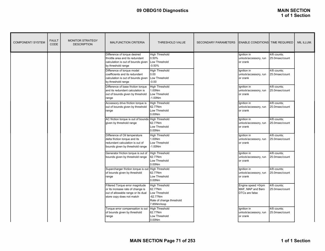
COMPONENT/ SYSTEM FAULT CODE
MONITOR STRATEGY DESCRIPTION MALFUNCTION CRITERIA THRESHOLD VALUE SECONDARY PARAMETERS ENABLE CONDITIONS TIME REQUIRED MIL ILLUM.
Difference of torque desired throttle area and its redundant calculation is out of bounds given by threshold range
High Threshold 0.50%Low Threshold-0.50%
Ignition in unlock/accessory, run or crank
4/8 counts; 25.0msec/count
Difference of torque model coefficients and its redundant calculation is out of bounds given by threshold range
High Threshold 0.00Low Threshold-0.00
Ignition in unlock/accessory, run or crank
4/8 counts; 25.0msec/count
Difference of base friction torque and its redundant calculation is out of bounds given by threshold range
High Threshold 1.00NmLow Threshold-1.00Nm
Ignition in unlock/accessory, run or crank
4/8 counts; 25.0msec/count
Accessory drive friction torque is out of bounds given by threshold range
High Threshold 62.77NmLow Threshold 0.00Nm
Ignition in unlock/accessory, run or crank
4/8 counts; 25.0msec/count
AC friction torque is out of bounds given by threshold range
High Threshold 62.77NmLow Threshold 0.00Nm
Ignition in unlock/accessory, run or crank
4/8 counts; 25.0msec/count
Difference of Oil temperature delta friction torque and its redundant calculation is out of bounds given by threshold range
High Threshold 1.00NmLow Threshold -1.00Nm
Ignition in unlock/accessory, run or crank
4/8 counts; 25.0msec/count
Generator friction torque is out of bounds given by threshold range
High Threshold 62.77NmLow Threshold 0.00Nm
Ignition in unlock/accessory, run or crank
4/8 counts; 25.0msec/count
Supercharger friction torque is out of bounds given by threshold range
High Threshold 62.77NmLow Threshold 0.00Nm
Ignition in unlock/accessory, run or crank
4/8 counts; 25.0msec/count
Filtered Torque error magnitude or its increase rate of change is out of allowable range or its dual store copy does not match
High Threshold 62.77NmLow Threshold -62.77NmRate of change threshold 7.85Nm/loop
Engine speed >0rpmMAF, MAP and Baro DTCs are false
4/8 counts; 25.0msec/count
Torque error compensation is out of bounds given by threshold range
High Threshold 62.77NmLow Threshold 0.00Nm
Ignition in unlock/accessory, run or crank
4/8 counts; 25.0msec/count
09 OBDG10 Diagnostics MAIN SECTION1 of 1 Section
MAIN SECTION Page 71 of 253 1 of 1 Section
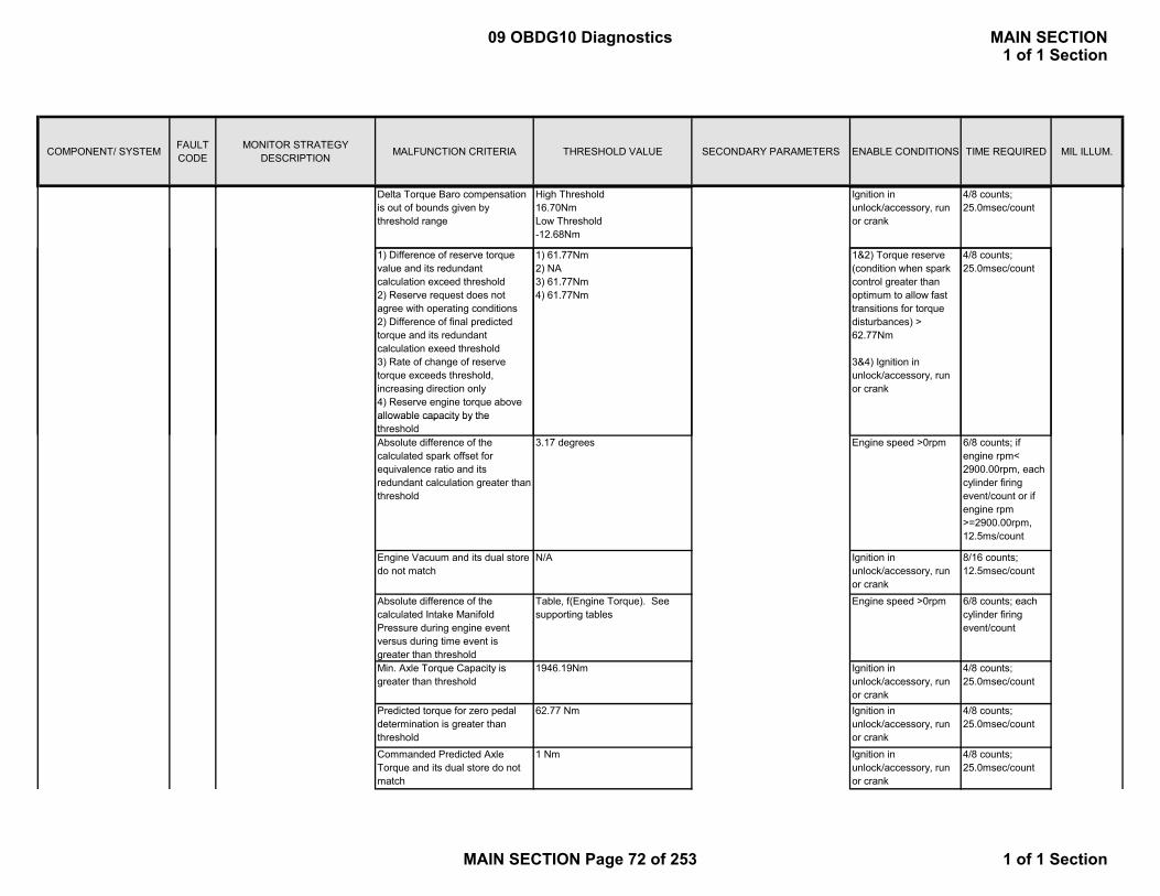
COMPONENT/ SYSTEM FAULT CODE
MONITOR STRATEGY DESCRIPTION MALFUNCTION CRITERIA THRESHOLD VALUE SECONDARY PARAMETERS ENABLE CONDITIONS TIME REQUIRED MIL ILLUM.
Delta Torque Baro compensation is out of bounds given by threshold range
High Threshold 16.70NmLow Threshold -12.68Nm
Ignition in unlock/accessory, run or crank
4/8 counts; 25.0msec/count
1) Difference of reserve torque value and its redundant calculation exceed threshold2) Reserve request does not agree with operating conditions2) Difference of final predicted torque and its redundant calculation exeed threshold3) Rate of change of reserve torque exceeds threshold, increasing direction only4) Reserve engine torque above allowable capacity by the
1) 61.77Nm2) NA3) 61.77Nm4) 61.77Nm
1&2) Torque reserve (condition when spark control greater than optimum to allow fast transitions for torque disturbances) > 62.77Nm
3&4) Ignition in unlock/accessory, run or crank
4/8 counts; 25.0msec/count
allowable capacity by the thresholdAbsolute difference of the calculated spark offset for equivalence ratio and its redundant calculation greater than threshold
3.17 degrees Engine speed >0rpm 6/8 counts; if engine rpm< 2900.00rpm, each cylinder firing event/count or if engine rpm >=2900.00rpm, 12.5ms/count
Engine Vacuum and its dual store do not match
N/A Ignition in unlock/accessory, run or crank
8/16 counts; 12.5msec/count
Absolute difference of the calculated Intake Manifold Pressure during engine event versus during time event is greater than threshold
Table, f(Engine Torque). See supporting tables
Engine speed >0rpm 6/8 counts; each cylinder firing event/count
Min. Axle Torque Capacity is greater than threshold
1946.19Nm Ignition in unlock/accessory, run or crank
4/8 counts; 25.0msec/count
Predicted torque for zero pedal determination is greater than threshold
62.77 Nm Ignition in unlock/accessory, run or crank
4/8 counts; 25.0msec/count
Commanded Predicted Axle Torque and its dual store do not match
1 Nm Ignition in unlock/accessory, run or crank
4/8 counts; 25.0msec/count
09 OBDG10 Diagnostics MAIN SECTION1 of 1 Section
MAIN SECTION Page 72 of 253 1 of 1 Section

COMPONENT/ SYSTEM FAULT CODE
MONITOR STRATEGY DESCRIPTION MALFUNCTION CRITERIA THRESHOLD VALUE SECONDARY PARAMETERS ENABLE CONDITIONS TIME REQUIRED MIL ILLUM.
Steady State Estimated Engine Torque and its dual store are not equal
N/A DoD not changing from Active to Inactive and preload torque not changing and one loop after React commandEngine speed >0rpm
4/8 counts; 25.0msec/count
Difference of Weighting factor for number of cylinders fueled and its redundant calculation is above threshold
0.26 Engine run flag = TRUE > 1.00s
6/8 counts; 25.0msec/count
Difference of minimum spark advance limit and its redundant calculation is out of bounds given by threshold range
3.17 degrees Ignition in unlock/accessory, run or crank
6/8 counts; if engine rpm< 4500rpm, 12.5msec/count or if engine rpm >=4500rpm, > 4500rpm, 50ms/count
Difference of commanded spark advance and adjusted delivered is out of bounds given by threshold range
3.17 degrees Engine speed >0rpm 6/8 counts; if engine rpm< 4500/4700rpm (hysteresis pair), each cylinder firing event/count or if engine rpm >=4500/4700rpm (hysteresis pair), 6.25ms/count
Estimated Engine Torque and its dual store are not match
62.77Nm Engine speed >0rpm 4/8 counts; 25.0msec/count
Estimated Engine Torque without reductions due to torque control and its dual store are not match
62.77Nm Engine speed >0rpm 4/8 counts; 25.0msec/count
Commanded Engine Torque from Hybrid control module and its dual store are not equal
N/A Ignition in unlock/accessory, run or crank
10/16 counts; 12.5msec/count
09 OBDG10 Diagnostics MAIN SECTION1 of 1 Section
MAIN SECTION Page 73 of 253 1 of 1 Section
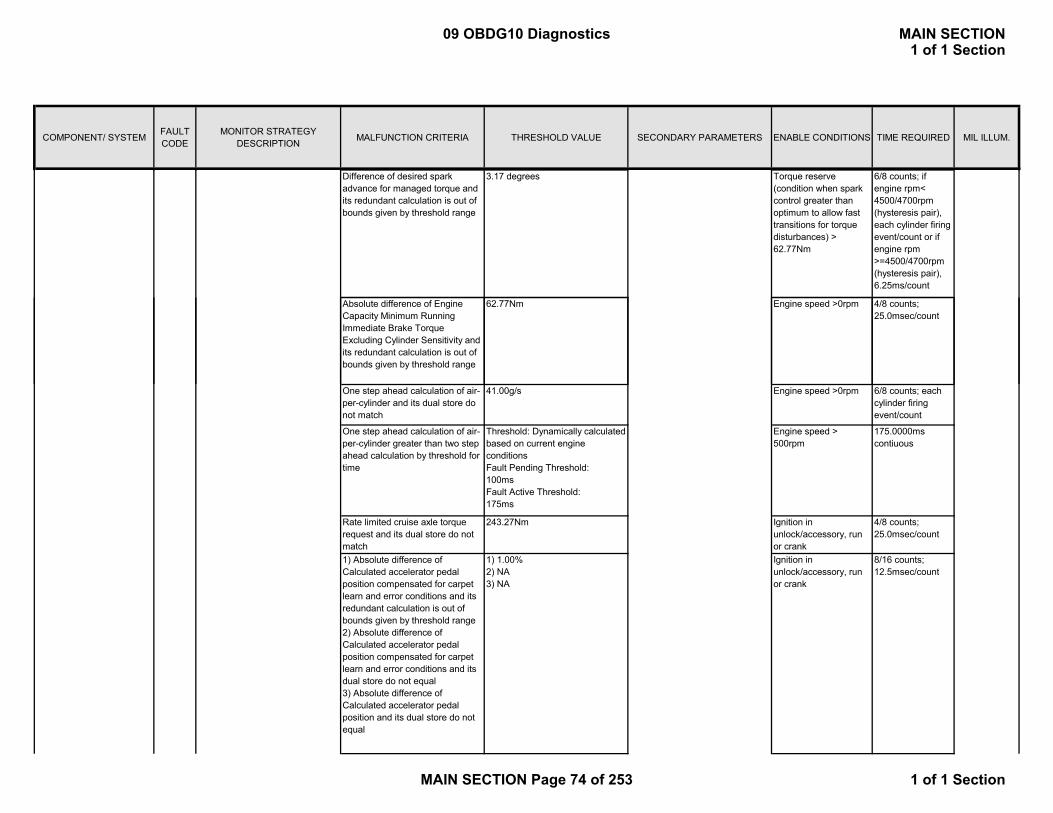
COMPONENT/ SYSTEM FAULT CODE
MONITOR STRATEGY DESCRIPTION MALFUNCTION CRITERIA THRESHOLD VALUE SECONDARY PARAMETERS ENABLE CONDITIONS TIME REQUIRED MIL ILLUM.
Difference of desired spark advance for managed torque and its redundant calculation is out of bounds given by threshold range
3.17 degrees Torque reserve (condition when spark control greater than optimum to allow fast transitions for torque disturbances) > 62.77Nm
6/8 counts; if engine rpm< 4500/4700rpm (hysteresis pair), each cylinder firing event/count or if engine rpm >=4500/4700rpm (hysteresis pair), 6.25ms/count
Absolute difference of Engine Capacity Minimum Running Immediate Brake Torque Excluding Cylinder Sensitivity and its redundant calculation is out of bounds given by threshold range
62.77Nm Engine speed >0rpm 4/8 counts; 25.0msec/count
One step ahead calculation of air-per-cylinder and its dual store do not match
41.00g/s Engine speed >0rpm 6/8 counts; each cylinder firing event/count
One step ahead calculation of air-per-cylinder greater than two step ahead calculation by threshold for time
Threshold: Dynamically calculated based on current engine conditionsFault Pending Threshold: 100msFault Active Threshold: 175ms
Engine speed > 500rpm
175.0000ms contiuous
Rate limited cruise axle torque request and its dual store do not match
243.27Nm Ignition in unlock/accessory, run or crank
4/8 counts; 25.0msec/count
1) Absolute difference of Calculated accelerator pedal position compensated for carpet learn and error conditions and its redundant calculation is out of bounds given by threshold range2) Absolute difference of Calculated accelerator pedal position compensated for carpet learn and error conditions and its dual store do not equal3) Absolute difference of Calculated accelerator pedal position and its dual store do not equal
1) 1.00%2) NA3) NA
Ignition in unlock/accessory, run or crank
8/16 counts; 12.5msec/count
09 OBDG10 Diagnostics MAIN SECTION1 of 1 Section
MAIN SECTION Page 74 of 253 1 of 1 Section
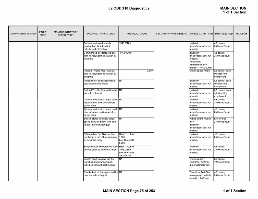
COMPONENT/ SYSTEM FAULT CODE
MONITOR STRATEGY DESCRIPTION MALFUNCTION CRITERIA THRESHOLD VALUE SECONDARY PARAMETERS ENABLE CONDITIONS TIME REQUIRED MIL ILLUM.
Commanded axle torque is greater than its redundant calculation by threshold
1946.00Nm Ignition in unlock/accessory, run or crank
4/8 counts; 25.0msec/count
Commanded axle torque is less than its redundant calculation by threshold
-1460.00Nm Ignition in unlock/accessory, run or crankRedundant commanded axle torque < --1460.00Nm
4/8 counts; 25.0msec/count
Preload Throttle Area is greater than its redundant calculation by threshold
0.10% Engine speed >0rpm 6/8 counts; each cylinder firing event/count
Preload timer and its redundant calculation do not equal
NA Ignition in unlock/accessory, run or crank
6/8 counts; each cylinder firing event/count
Preload Throttle Area and its dual store do not equal
NA Ignition in unlock/accessory run
6/8 counts; each cylinder firingstore do not equal unlock/accessory, run
or crankcylinder firing event/count
Commanded engine torque due to fast actuators and its dual store do not equal
NA Ignition in unlock/accessory, run or crank
4/8 counts; 25.0msec/count
Commanded engine torque due to slow actuators and its dual store do not equal
NA Ignition in unlock/accessory, run or crank
4/8 counts; 25.0msec/count
Signed filtered defaulted output speed calculated from TOS and its dual store do not equal
NA Hybrid control module onlyIgnition in unlock/accessory, run or crank
5/15 counts; 25.0msec/count
Arbitrated Air-Per-Cylinder filter coefficient is out of bounds given by threshold range
High Threshold 1.000Low Threshold 0.200
Ignition in unlock/accessory, run or crank
4/8 counts; 25.0msec/count
Shaped driver axle torque is out of bounds given by threshold range
High Threshold 1946.00NmLow Threshold -2920.00Nm
Ignition in unlock/accessory, run or crank
4/8 counts; 25.0msec/count
Launch spark is active but the launch spark redundant path indicates it should not be active
NA Engine speed < 4500.00 or 4700.00 rpm (hysteresis pair)
6/8 counts; 12.5msec/count
Rate limited vehicle speed and its dual store do not equal
NA Time since first CAN message with vehicle speed >= 0.500sec
4/8 counts; 25.0msec/count
09 OBDG10 Diagnostics MAIN SECTION1 of 1 Section
MAIN SECTION Page 75 of 253 1 of 1 Section

COMPONENT/ SYSTEM FAULT CODE
MONITOR STRATEGY DESCRIPTION MALFUNCTION CRITERIA THRESHOLD VALUE SECONDARY PARAMETERS ENABLE CONDITIONS TIME REQUIRED MIL ILLUM.
transfer case neutral and its dual store do not equal
NA Ignition in unlock/accessory, run or crank
4/8 counts; 25.0msec/count
Throttle progression mode and its dual store do not equal
NA Ignition in unlock/accessory, run or crank
8/16 counts; 12.5msec/count
TOS to wheel speed conversion factor is out of bounds given by threshold range
High Threshold 1.10 T/C Range Hi0.10 T/C Range LoLow Threshold 1.10 T/C Range Hi0.10 T/C Range Lo
Ignition in unlock/accessory, run or crank
4/8 counts; 25.0msec/count
TOS to wheel speed conversion factor and its dual store do not equal
NA Ignition in unlock/accessory, run or crank
5/15 counts; 25.0msec/count
Cylinders active greater than 2 cylinders Engine run flag = 6/8 counts; each y gcommanded
y g gTRUE > 2.00sNumber of cylinder events since engine run > 24No fuel injector faults active
;cylinder firing event/count
Absolute difference of Friction torque and its redundant calculation is out of bounds given by threshold range
62.77Nm Ignition in unlock/accessory, run or crank
4/8 counts; 25.0msec/count
Absolute difference of Accessory torque and its redundant calculation is out of bounds given by threshold range
62.77Nm Ignition in unlock/accessory, run or crank
4/8 counts; 25.0msec/count
Absolute difference of Filtered Air-per-cylinder and its redundant calculation is out of bounds given by threshold range
41.00mg Ignition in unlock/accessory, run or crank
4/8 counts; 25.0msec/count
Absolute difference between the previous Final Advance and the current Final Advance not Adjusted for Equivalence Ratio is out of bounds given by threshold range
3.17degrees 6/8 counts; if engine rpm< 4500/4700rpm (hysteresis pair), each cylinder firing event/count or if engine rpm >=4500/4700rpm (hysteresis pair), 6.25ms/count
09 OBDG10 Diagnostics MAIN SECTION1 of 1 Section
MAIN SECTION Page 76 of 253 1 of 1 Section

COMPONENT/ SYSTEM FAULT CODE
MONITOR STRATEGY DESCRIPTION MALFUNCTION CRITERIA THRESHOLD VALUE SECONDARY PARAMETERS ENABLE CONDITIONS TIME REQUIRED MIL ILLUM.
Equivance Ratio torque compensation exceeds threshold
-62.77Nm Ignition in unlock/accessory, run or crank
4/8 counts; 25.0msec/count
Absolute difference between Equivance Ratio torque compensation and its dual store out of bounds given bt threshold
62.77Nm Ignition in unlock/accessory, run or crank
4/8 counts; 25.0msec/count
Zero pedal axle torque is out of bounds given by threshold range
High Threshold 1946.00NmLow Threshold -1500.00Nm
Ignition in unlock/accessory, run or crank
4/8 counts; 25.0msec/count
Creep Coast Axle Torque is out of bounds given by threshold range
High Threshold 1946.00NmLow Threshold -1500.00Nm
Ignition in unlock/accessory, run or crank
4/8 counts; 25.0msec/count
P2101 Run/crank voltage or Powertrain relay voltage > 6.00 and reduced power is false, else the failure will be reported for all conditions
1. 15/15 counts; 12.5 msec/count in the primary processor
Type A 1 trip
TPS minimum learn is not active andThrottle is being Controlled and
(Engine Running or Ignition Voltage > 11ORIgnition Voltage > 5.5Ignition voltage failure is false (P1682)
39.26% TPS minimum learn is active 2. 11counts; 12.5 msec/count in the primary processor
Thottle Position > 39.06% Reduced Power is True
P2120 Secondary APP1 Voltage < 0.463 Run/crank voltage or Powertrain relay voltage > 6.00 and reduced power is false, else the failure will be reported for all conditions
Type A 1 trip
Difference between measured throttle position and modeled
Detects a continuous or intermittent short or open in APP1 circuit on the secondary processor but sensor is in range on the primary processor
Accelerator Pedal Position (APP) Sensor #1
Control Module Throttle Actuator Position Performance
7.20%
2) Detect throttle control is driving the throttle in the incorrect direction or exceed the reduced power limit
Thottle Position >
1) Detect a throttle positioning error
Difference between measured throttle position and modeled throttle position >
7.20%
19/39counts or 14counts continuous; 12.5 msec/count in the secondary processor
09 OBDG10 Diagnostics MAIN SECTION1 of 1 Section
MAIN SECTION Page 77 of 253 1 of 1 Section
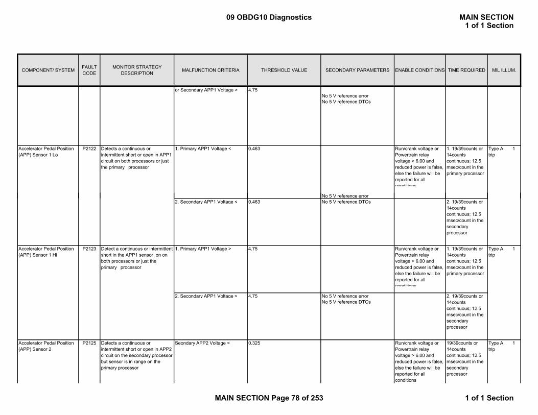
COMPONENT/ SYSTEM FAULT CODE
MONITOR STRATEGY DESCRIPTION MALFUNCTION CRITERIA THRESHOLD VALUE SECONDARY PARAMETERS ENABLE CONDITIONS TIME REQUIRED MIL ILLUM.
or Secondary APP1 Voltage > 4.75No 5 V reference error No 5 V reference DTCs
Accelerator Pedal Position (APP) Sensor 1 Lo
P2122 Detects a continuous or intermittent short or open in APP1 circuit on both processors or just the primary processor
1. Primary APP1 Voltage < 0.463 Run/crank voltage or Powertrain relay voltage > 6.00 and reduced power is false, else the failure will be reported for all conditions
Type A 1 trip
N 5 V f
1. 19/39counts or 14counts continuous; 12.5 msec/count in the primary processor
No 5 V reference error 2. Secondary APP1 Voltage < 0.463 No 5 V reference DTCs
Accelerator Pedal Position (APP) Sensor 1 Hi
P2123 Detect a continuous or intermittent short in the APP1 sensor on on both processors or just the primary processor
1. Primary APP1 Voltage > 4.75 Run/crank voltage or Powertrain relay voltage > 6.00 and reduced power is false, else the failure will be reported for all conditions
Type A 1 trip
2. Secondary APP1 Voltage > 4.75 No 5 V reference error No 5 V reference DTCs
P2125 Seondary APP2 Voltage < 0.325 Run/crank voltage or Powertrain relay voltage > 6.00 and reduced power is false, else the failure will be reported for all conditions
Type A 1 trip
2. 19/39counts or 14counts continuous; 12.5 msec/count in the secondary processor
1. 19/39counts or 14counts continuous; 12.5 msec/count in the primary processor
Accelerator Pedal Position (APP) Sensor 2
Detects a continuous or intermittent short or open in APP2 circuit on the secondary processor but sensor is in range on the primary processor
2. 19/39counts or 14counts continuous; 12.5 msec/count in the secondary processor
19/39counts or 14counts continuous; 12.5 msec/count in the secondary processor
09 OBDG10 Diagnostics MAIN SECTION1 of 1 Section
MAIN SECTION Page 78 of 253 1 of 1 Section
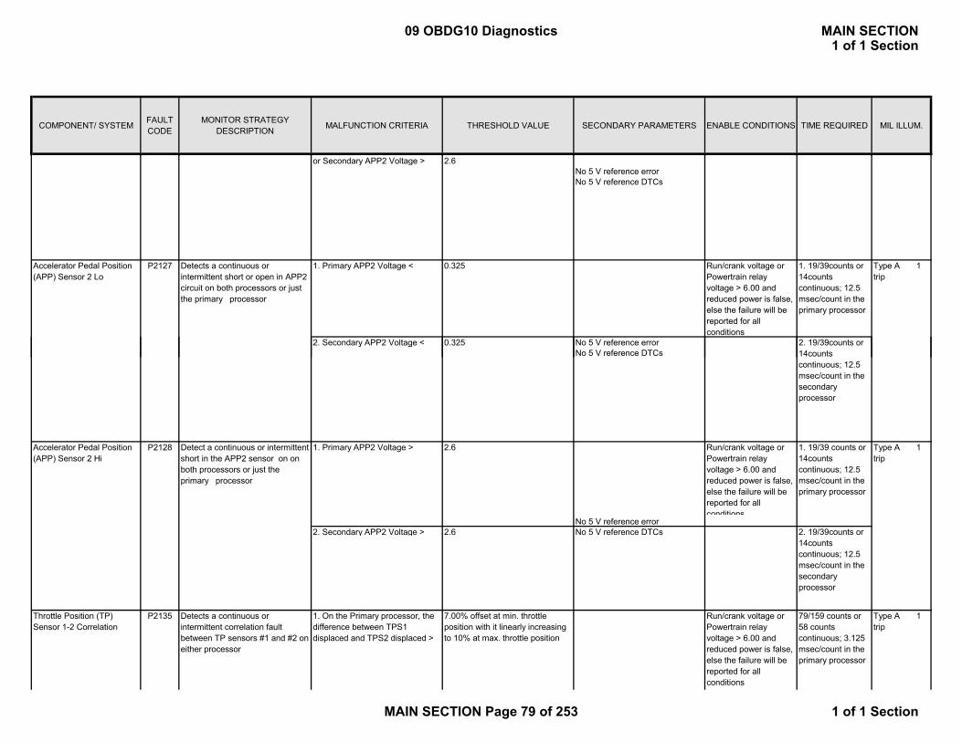
COMPONENT/ SYSTEM FAULT CODE
MONITOR STRATEGY DESCRIPTION MALFUNCTION CRITERIA THRESHOLD VALUE SECONDARY PARAMETERS ENABLE CONDITIONS TIME REQUIRED MIL ILLUM.
or Secondary APP2 Voltage > 2.6No 5 V reference error No 5 V reference DTCs
Accelerator Pedal Position (APP) Sensor 2 Lo
P2127 Detects a continuous or intermittent short or open in APP2 circuit on both processors or just the primary processor
1. Primary APP2 Voltage < 0.325 Run/crank voltage or Powertrain relay voltage > 6.00 and reduced power is false, else the failure will be reported for all conditions
1. 19/39counts or 14counts continuous; 12.5 msec/count in the primary processor
Type A 1 trip
2. Secondary APP2 Voltage < 0.325 No 5 V reference error 2. 19/39counts or y gNo 5 V reference DTCs
Accelerator Pedal Position (APP) Sensor 2 Hi
P2128 Detect a continuous or intermittent short in the APP2 sensor on on both processors or just the primary processor
1. Primary APP2 Voltage > 2.6 Run/crank voltage or Powertrain relay voltage > 6.00 and reduced power is false, else the failure will be reported for all conditions
Type A 1 trip
No 5 V reference error 2. Secondary APP2 Voltage > 2.6 No 5 V reference DTCs
Throttle Position (TP) Sensor 1-2 Correlation
P2135 Run/crank voltage or Powertrain relay voltage > 6.00 and reduced power is false, else the failure will be reported for all conditions
Type A 1 trip
79/159 counts or 58 counts continuous; 3.125 msec/count in the primary processor
Detects a continuous or intermittent correlation fault between TP sensors #1 and #2 on either processor
1. On the Primary processor, the difference between TPS1 displaced and TPS2 displaced >
7.00% offset at min. throttle position with it linearly increasing to 10% at max. throttle position
14counts continuous; 12.5 msec/count in the secondary processor
1. 19/39 counts or 14counts continuous; 12.5 msec/count in the primary processor
2. 19/39counts or 14counts continuous; 12.5 msec/count in the secondary processor
09 OBDG10 Diagnostics MAIN SECTION1 of 1 Section
MAIN SECTION Page 79 of 253 1 of 1 Section
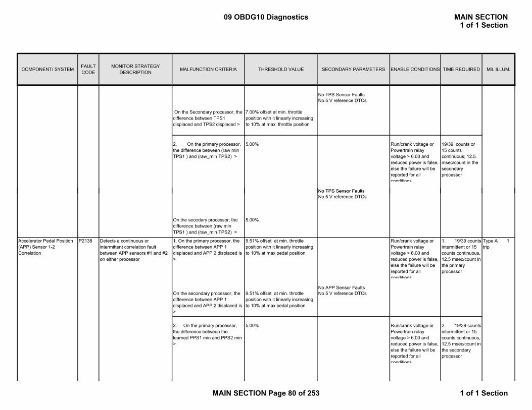
COMPONENT/ SYSTEM FAULT CODE
MONITOR STRATEGY DESCRIPTION MALFUNCTION CRITERIA THRESHOLD VALUE SECONDARY PARAMETERS ENABLE CONDITIONS TIME REQUIRED MIL ILLUM.
No TPS Sensor FaultsNo 5 V reference DTCs
On the Secondary processor, the difference between TPS1 displaced and TPS2 displaced >
7.00% offset at min. throttle position with it linearly increasing to 10% at max. throttle position
Run/crank voltage or Powertrain relay voltage > 6.00 and reduced power is false, else the failure will be reported for all conditions
No TPS Sensor Faults
19/39 counts or 15 counts continuous; 12.5 msec/count in the secondary processor
2. On the primary processor, the difference between (raw min TPS1 ) and (raw_min TPS2) >
5.00%
No TPS Sensor FaultsNo 5 V reference DTCs
On the secodary processor, the difference between (raw min TPS1 ) and (raw_min TPS2) >
5.00%
Detects a continuous or intermittent correlation fault between APP sensors #1 and #2 on either processor
Run/crank voltage or Powertrain relay voltage > 6.00 and reduced power is false, else the failure will be reported for all conditions
Type A 1 trip
No APP Sensor FaultsOn the secondary processor, the difference between APP 1 displaced and APP 2 displaced is >
9.51% offset at min. throttle position with it linearly increasing to 10% at max pedal position
No 5 V reference DTCs
Run/crank voltage or Powertrain relay voltage > 6.00 and reduced power is false, else the failure will be reported for all conditions
1. 19/39 counts intermittent or 15 counts continuous, 12.5 msec/count in the primary processor
2. 19/39 counts intermittent or 15 counts continuous, 12.5 msec/count in the secondary processor
Accelerator Pedal Position (APP) Sensor 1-2 Correlation
P2138 1. On the primary processor, the difference between APP 1 displaced and APP 2 displaced is >
5.00%
9.51% offset at min. throttle position with it linearly increasing to 10% at max pedal position
2. On the primary processor, the difference between the learned PPS1 min and PPS2 min >
09 OBDG10 Diagnostics MAIN SECTION1 of 1 Section
MAIN SECTION Page 80 of 253 1 of 1 Section

COMPONENT/ SYSTEM FAULT CODE
MONITOR STRATEGY DESCRIPTION MALFUNCTION CRITERIA THRESHOLD VALUE SECONDARY PARAMETERS ENABLE CONDITIONS TIME REQUIRED MIL ILLUM.
5.00%
TCSS signal < = 50 rpm Engine Torque >= 60nm <= 8192 nm 5.0 SecondsThrottle Position >= 5 % <= 99%
Input Speed >= 1000 rpm <= 7500 rpm
Continuous
4WDOnly
Not in Reverse Inhibit stateNot garage shifting
Engine Speed > 1000 rpm 4.0 Seconds
Continuous4WDOnly
(Current TCSS signal – Last Valid Output Speed)
Vehicle Speed Sensor B Intermittent/Erratic
Output Speed signal is increasing
Vehicle Speed Sensor B Circuit Low
P2160
>= 475 rpmTransmission Range ≠ Park or Neutral
Transmission Range ≠ Park or Neutral
P2161
TNo signal from Transfer Case Speed Sensor
On the primary processor, the difference between the learned PPS1 min and PPS2 min >
Loss of signal from Transfer Case Speed Sensor
Type:B 2 trips
Type:B 2 trips
OnlyNot in Reverse Inhibit state
Or Not garage shifting
<= 225 rpm
Minimum Throttle Position Not Learned
P2176 TP sensors were not in the minmum learn window after multiple attempts to learn the minimum.
During TPS min learn on the Primary processor, TPS Voltage >
18.70% Run/crank voltage or Powertrain relay voltage > 6.00 and reduced power is false, else the failure will be reported for all conditions
2.0secs continuous
Type A 1 trip
orNo TPS circuit errorsNo TPS circuit faultsIgnition voltage failure is false (P1682)Minimum TPS learn active
andNumber of learn attempts > 10counts
(Current TCSS signal – Last Valid Output Speed)
Output Speed signal is decreasing
18.70%
Neutral
During TPS min learn on the Secondary processor, TPS Voltage >
09 OBDG10 Diagnostics MAIN SECTION1 of 1 Section
MAIN SECTION Page 81 of 253 1 of 1 Section
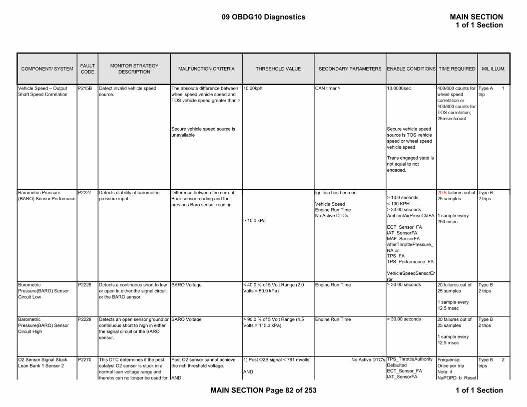
COMPONENT/ SYSTEM FAULT CODE
MONITOR STRATEGY DESCRIPTION MALFUNCTION CRITERIA THRESHOLD VALUE SECONDARY PARAMETERS ENABLE CONDITIONS TIME REQUIRED MIL ILLUM.
Vehicle Speed – Output Shaft Speed Correlation
P215B Detect invalid vehicle speed source.
The absolute difference between wheel speed vehicle speed and TOS vehicle speed greater than >
10.00kph CAN timer > 10.0000sec 400/800 counts for wheel speed correlation or 400/800 counts for TOS correlation; 25msec/count
Type A 1 trip
Secure vehicle speed source is unavailable
Secure vehicle speed source is TOS vehicle speed or wheel speed vehicle speed
Trans engaged state is not equal to not engaged.
B t i P P2227 20 5 f il t fD t t t bilit f b t i T BI iti h bDiff b t th t
Vehicle Speed < 100 KPHEngine Run Time > 30.00 secondsNo Active DTCs: AmbientAirPressCktFA
ECT_Sensor_FAIAT_SensorFAMAF_SensorFA
TPS_FATPS_Performance_FA
VehicleSpeedSensorError
BARO Voltage Engine Run Time > 30.00 seconds
BARO Voltage Engine Run Time > 30.00 seconds
No Active DTC's TPS_ThrottleAuthorityDefaultedECT_Sensor_FAIAT_SensorFA
Barometric Pressure(BARO) Sensor Circuit High
P2229
O2 Sensor Signal Stuck Lean Bank 1 Sensor 2
P2270
Barometric Pressure (BARO) Sensor Performace
P2227
Frequency:Once per tripNote: if NaPOPD b Reset
Type B 2 trips
20 5 failures out of 25 samples
1 sample every 12.5 msec
1 sample every 250 msec
20 failures out of 25 samples
20 failures out of 25 samples
Detects stability of barometric pressure input
Detects an open sensor ground or continuous short to high in either the signal circuit or the BARO sensor.
> 90.0 % of 5 Volt Range (4.5 Volts = 115.3 kPa)
Barometric Pressure(BARO) Sensor Circuit Low
P2228 Detects a continuous short to low or open in either the signal circuit or the BARO sensor.
< 40.0 % of 5 Volt Range (2.0 Volts = 50.9 kPa)
Type B2 trips
1 sample every 12.5 msec
Type B2 trips
Type B2 trips
Ignition has been on
AfterThrottlePressure_NA or
> 10.0 kPa
Difference between the current Baro sensor reading and the previous Baro sensor reading
This DTC determines if the post catalyst O2 sensor is stuck in a normal lean voltage range and thereby can no longer be used for
Post O2 sensor cannot achieve the rich threshold voltage.
AND
1) Post O2S signal < 791 mvolts
AND
> 10.0 seconds
09 OBDG10 Diagnostics MAIN SECTION1 of 1 Section
MAIN SECTION Page 82 of 253 1 of 1 Section
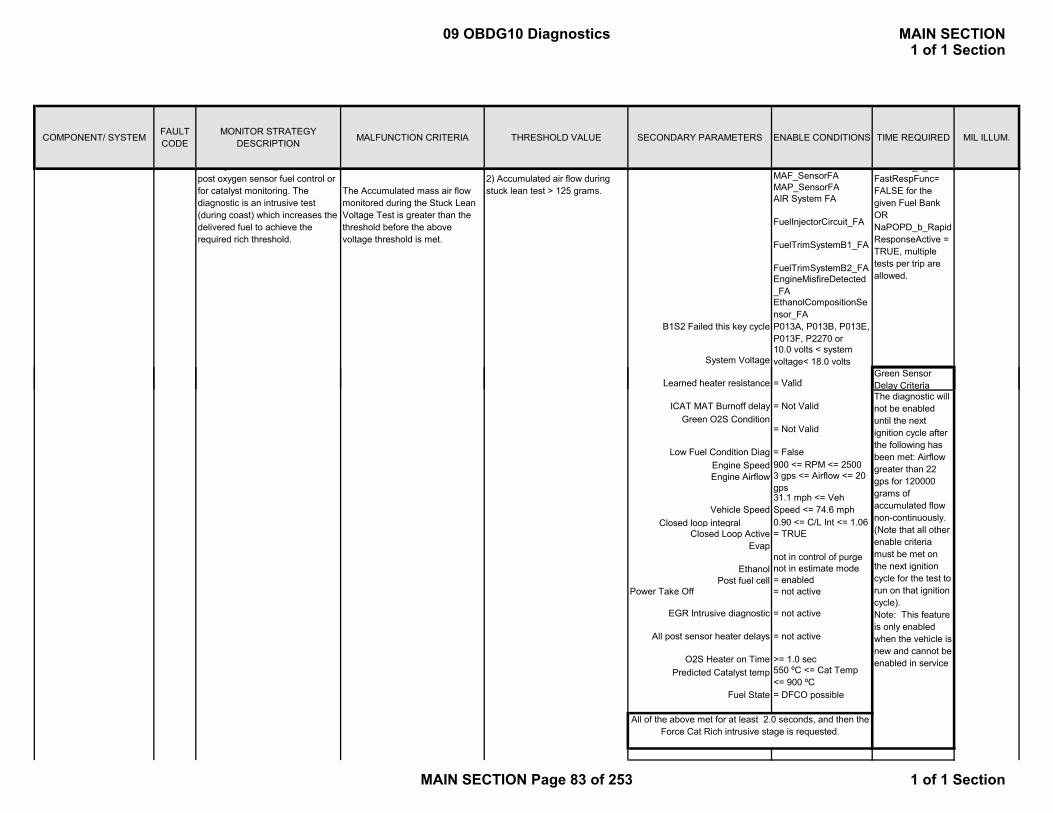
COMPONENT/ SYSTEM FAULT CODE
MONITOR STRATEGY DESCRIPTION MALFUNCTION CRITERIA THRESHOLD VALUE SECONDARY PARAMETERS ENABLE CONDITIONS TIME REQUIRED MIL ILLUM.
MAF_SensorFAMAP_SensorFAAIR System FA
FuelInjectorCircuit_FA
FuelTrimSystemB1_FA
FuelTrimSystemB2_FAEngineMisfireDetected_FAEthanolCompositionSensor_FA
_ _FastRespFunc= FALSE for the given Fuel Bank OR NaPOPD_b_RapidResponseActive = TRUE, multiple tests per trip are allowed.
Green Sensor System Voltage
Learned heater resistance
B1S2 Failed this key cycle
10.0 volts < system voltage< 18.0 volts
= Valid
P013A, P013B, P013E, P013F, P2270 or
y gpost oxygen sensor fuel control or for catalyst monitoring. The diagnostic is an intrusive test (during coast) which increases the delivered fuel to achieve the required rich threshold.
The Accumulated mass air flow monitored during the Stuck Lean Voltage Test is greater than the threshold before the above voltage threshold is met.
2) Accumulated air flow during stuck lean test > 125 grams.
Engine Speed 900 <= RPM <= 2500Engine Airflow 3 gps <= Airflow <= 20
gps
Closed loop integral 0.90 <= C/L Int <= 1.06Closed Loop Active = TRUE
Evap not in control of purge
Ethanol not in estimate modePost fuel cell = enabled
Power Take Off = not active
Fuel State = DFCO possible
EGR Intrusive diagnostic
= not active
Predicted Catalyst temp 550 ºC <= Cat Temp <= 900 ºC
All of the above met for at least 2.0 seconds, and then the Force Cat Rich intrusive stage is requested.
>= 1.0 sec
= not active
The diagnostic will not be enabled until the next ignition cycle after the following has been met: Airflow greater than 22 gps for 120000 grams of accumulated flow non-continuously. (Note that all other enable criteria must be met on the next ignition cycle for the test to run on that ignition cycle).Note: This feature is only enabled when the vehicle is new and cannot be enabled in service
= Not ValidGreen O2S Condition
= Not Valid
Delay Criteria
All post sensor heater delays
ICAT MAT Burnoff delay
Learned heater resistance
= False
31.1 mph <= Veh Speed <= 74.6 mph
= Valid
Vehicle Speed
Low Fuel Condition Diag
O2S Heater on Time
09 OBDG10 Diagnostics MAIN SECTION1 of 1 Section
MAIN SECTION Page 83 of 253 1 of 1 Section

COMPONENT/ SYSTEM FAULT CODE
MONITOR STRATEGY DESCRIPTION MALFUNCTION CRITERIA THRESHOLD VALUE SECONDARY PARAMETERS ENABLE CONDITIONS TIME REQUIRED MIL ILLUM.
No Active DTC's TPS_ThrottleAuthorityDefaultedECT_Sensor_FAIAT_SensorFAMAF_SensorFAMAP_SensorFAAIR System FA
FuelInjectorCircuit_FA
FuelTrimSystemB1_FA
FuelTrimSystemB2_FAEngineMisfireDetected_FAEthanolCompositionSensor_FA
P2271O2 Sensor Signal Stuck Rich Bank 1 Sensor 2
Type B 2 trips
B1S2 Failed this key cycle P013A, P013B, P013E, P013F P2270
Frequency:Once per tripNote: if NaPOPD_b_ResetFastRespFunc= FALSE for the given Fuel Bank OR NaPOPD_b_RapidResponseActive = TRUE, multiple tests per trip are allowed.
This DTC determines if the post catalyst O2 sensor is stuck in a normal rich voltage range and thereby can no longer be used for post oxygen sensor fuel control or for catalyst monitoring. The diagnostic is an intrusive test which requests the DFCO mode to achieve the required lean threshold.
1) Post O2S signal > 100 mvolts
AND
2) Accumulated air flow during stuck rich test > 65 grams.
Post O2 sensor cannot achieve the lean threshold voltage.
AND
The Accumulated mass air flow monitored during the Stuck Rich Voltage Test is greater than the threshold before the above voltage threshold is met.
Engine Speed 900 <= RPM <= 2500
Closed loop integral 0.90 <= C/L Int <= 1.06Closed Loop Active = TRUE
Evap not in control of purge
Ethanol not in estimate modePost fuel cell = enabled
Power Take Off = not active
Fuel State = DFCO possible
Learned heater resistance
DTC's Passed = P2270 (and P2272 (if
>= 1.0 sec
Predicted Catalyst temp550 ºC <= Cat Temp <= 900 ºC
= Valid
= not active
3 gps <= Airflow <= 20 gps
Vehicle Speed
ICAT MAT Burnoff delay = Not ValidGreen O2S Condition
31.1 mph <= Veh Speed <= 74.6 mph
Low Fuel Condition Diag = False
= Not Valid
All post sensor heater delays = not active
Engine Airflow
O2S Heater on Time
EGR Intrusive diagnostic
P013F or P2270
System Voltage10.0 volts < system voltage< 18.0 volts
Green Sensor Delay CriteriaThe diagnostic will not be enabled until the next ignition cycle after the following has been met: Airflow greater than 22 gps for 120000 grams of accumulated flow non-continuously. (Note that all other enable criteria must be met on the next ignition cycle for the test to run on that ignition cycle).Note: This feature is only enabled when the vehicle is new and cannot be enabled in service
09 OBDG10 Diagnostics MAIN SECTION1 of 1 Section
MAIN SECTION Page 84 of 253 1 of 1 Section
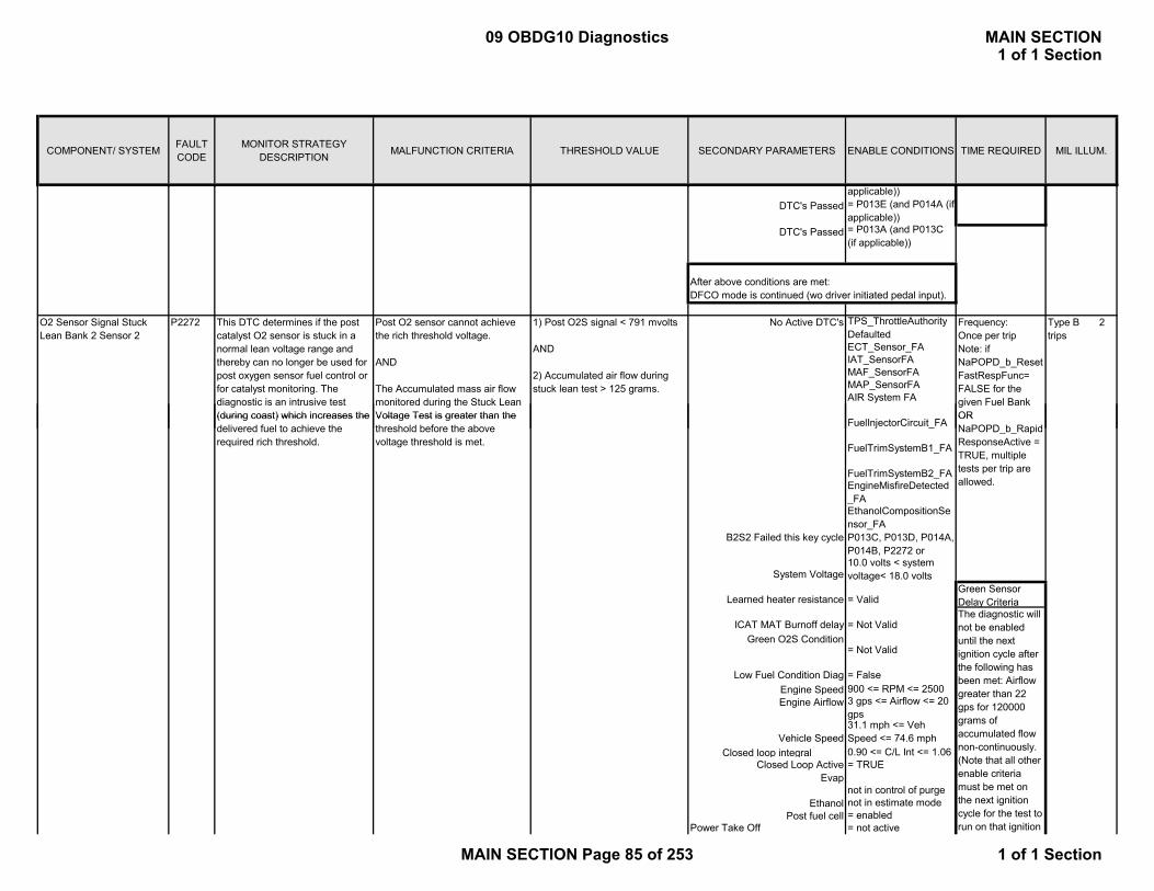
COMPONENT/ SYSTEM FAULT CODE
MONITOR STRATEGY DESCRIPTION MALFUNCTION CRITERIA THRESHOLD VALUE SECONDARY PARAMETERS ENABLE CONDITIONS TIME REQUIRED MIL ILLUM.
No Active DTC's TPS_ThrottleAuthorityDefaultedECT_Sensor_FAIAT_SensorFAMAF_SensorFAMAP_SensorFAAIR System FA
O2 Sensor Signal Stuck Lean Bank 2 Sensor 2
P2272 1) Post O2S signal < 791 mvolts
AND
2) Accumulated air flow during stuck lean test > 125 grams.
DTC's Passed = P013E (and P014A (if applicable))
DTC's Passed = P013A (and P013C (if applicable))
applicable))
After above conditions are met: DFCO mode is continued (wo driver initiated pedal input).
Frequency:Once per tripNote: if NaPOPD_b_ResetFastRespFunc= FALSE for the given Fuel Bank OR
Type B 2 trips
This DTC determines if the post catalyst O2 sensor is stuck in a normal lean voltage range and thereby can no longer be used for post oxygen sensor fuel control or for catalyst monitoring. The diagnostic is an intrusive test (during coast) which increases the
Post O2 sensor cannot achieve the rich threshold voltage.
AND
The Accumulated mass air flow monitored during the Stuck Lean Voltage Test is greater than the
FuelInjectorCircuit_FA
FuelTrimSystemB1_FA
FuelTrimSystemB2_FAEngineMisfireDetected_FAEthanolCompositionSensor_FA
Engine Speed 900 <= RPM <= 2500Engine Airflow 3 gps <= Airflow <= 20
gps
Closed loop integral 0.90 <= C/L Int <= 1.06Closed Loop Active = TRUE
Evap not in control of purge
Ethanol not in estimate modePost fuel cell = enabled
Power Take Off = not active
ICAT MAT Burnoff delay = Not Valid
OR NaPOPD_b_RapidResponseActive = TRUE, multiple tests per trip are allowed.
31.1 mph <= Veh Speed <= 74.6 mph
Green Sensor Delay CriteriaThe diagnostic will not be enabled until the next ignition cycle after the following has been met: Airflow greater than 22 gps for 120000 grams of accumulated flow non-continuously. (Note that all other enable criteria must be met on the next ignition cycle for the test to run on that ignition
B2S2 Failed this key cycle
Vehicle Speed
= Not Valid
= False
= Valid
10.0 volts < system voltage< 18.0 volts
Low Fuel Condition Diag
Green O2S Condition
Learned heater resistance
P013C, P013D, P014A, P014B, P2272 or
System Voltage
(during coast) which increases the delivered fuel to achieve the required rich threshold.
Voltage Test is greater than the threshold before the above voltage threshold is met.
09 OBDG10 Diagnostics MAIN SECTION1 of 1 Section
MAIN SECTION Page 85 of 253 1 of 1 Section

COMPONENT/ SYSTEM FAULT CODE
MONITOR STRATEGY DESCRIPTION MALFUNCTION CRITERIA THRESHOLD VALUE SECONDARY PARAMETERS ENABLE CONDITIONS TIME REQUIRED MIL ILLUM.
Fuel State = DFCO possible
No Active DTC's TPS_ThrottleAuthorityDefaultedECT_Sensor_FAIAT_SensorFA
O2 Sensor Signal Stuck Rich Bank 2 Sensor 2
P2273
All of the above met for at least 2.0 seconds, and then the Force Cat Rich intrusive stage is requested.
cycle).Note: This feature is only enabled when the vehicle is new and cannot be enabled in service
= not active
>= 1.0 sec
Frequency:Once per tripNote: if NaPOPD_b_Reset
Type B 2 trips
All post sensor heater delays
O2S Heater on TimePredicted Catalyst temp
= not activeEGR Intrusive diagnostic
550 ºC <= Cat Temp <= 900 ºC
This DTC determines if the post catalyst O2 sensor is stuck in a normal rich voltage range and thereby can no longer be used for
Post O2 sensor cannot achieve the lean threshold voltage.
AND
1) Post O2S signal > 100 mvolts
AND
MAF_SensorFAMAP_SensorFAAIR System FA
FuelInjectorCircuit_FA
FuelTrimSystemB1_FA
FuelTrimSystemB2_FAEngineMisfireDetected_FAEthanolCompositionSensor_FA
Engine Speed 900 <= RPM <= 2500
Closed loop integral 0.90 <= C/L Int <= 1.06Closed Loop Active = TRUE
B2S2 Failed this key cycle P013C, P013D, P014A, P014B or P2272
System Voltage
Vehicle Speed
Engine Airflow
ICAT MAT Burnoff delayGreen O2S Condition
Low Fuel Condition Diag
The diagnostic will not be enabled until the next ignition cycle after the following has been met: Airflow greater than 22 gps for 120000 grams of accumulated flow non-continuously. (Note that all other
bl it i
31.1 mph <= Veh Speed <= 74.6 mph
Learned heater resistance
NaPOPD_b_ResetFastRespFunc= FALSE for the given Fuel Bank OR NaPOPD_b_RapidResponseActive = TRUE, multiple tests per trip are allowed.
= Not Valid
= False
3 gps <= Airflow <= 20 gps
10.0 volts < system voltage< 18.0 volts
= ValidGreen Sensor Delay Criteria
= Not Valid
thereby can no longer be used for post oxygen sensor fuel control or for catalyst monitoring. The diagnostic is an intrusive test which requests the DFCO mode to achieve the required lean threshold.
AND
The Accumulated mass air flow monitored during the Stuck Rich Voltage Test is greater than the threshold before the above voltage threshold is met.
2) Accumulated air flow during stuck rich test > 65 grams.
09 OBDG10 Diagnostics MAIN SECTION1 of 1 Section
MAIN SECTION Page 86 of 253 1 of 1 Section

COMPONENT/ SYSTEM FAULT CODE
MONITOR STRATEGY DESCRIPTION MALFUNCTION CRITERIA THRESHOLD VALUE SECONDARY PARAMETERS ENABLE CONDITIONS TIME REQUIRED MIL ILLUM.
Evap not in control of purge
Ethanol not in estimate modePost fuel cell = enabled
Power Take Off = not active
Fuel State = DFCO possible
All post sensor heater delays = not active
EGR Intrusive diagnostic
DTC's Passed = P013E (and P014A (if applicable))
>= 1.0 sec
Predicted Catalyst temp550 ºC <= Cat Temp <= 900 ºC
= P2270 (and P2272 (if applicable))
O2S Heater on Time
enable criteria must be met on the next ignition cycle for the test to run on that ignition cycle).Note: This feature is only enabled when the vehicle is new and cannot be enabled in service
= P013A (and P013C
= not active
DTC' P d
DTC's Passed
Initial value test:Initial ignition off timer value < 0 seconds
ECM is powered down Initial value test: Type B 2 trips
OR IAT Temperature -40 °C ≤ Temperature ≤ 125 °C
3 failures
Initial ignition off timer value > 10 seconds
1.375 sec / sample
Clock rate test: Clock rate test:Time between ignition off timer
increments < .8 seconds8 failures out of 10 samples
Time between ignition off timer increments > 1.2 seconds
1second / sample
Time since last ignition off timer increment ≥ 1.375 seconds
test runs once each key-off
Current ignition off time < old ignition off time
Current ignition off timer minus old ignition off timer
≠ 1
ECM/PCM Internal Engine Off Timer Performance
Engine Hood Switch Circuit
= P013A (and P013C (if applicable))
After above conditions are met: DFCO mode is continued (wo driver initiated pedal input).
This DTC determines if the engine off timer does not initialize or count properly.
Clock rate test:Checks the accuracy of the 1 second timer by comparing it with the 12.5 ms timer
P2610
DTC sets on next key cycle if failure detected
DTC's Passed
Type B 2 trips
P254F Circuit Performance Hood Switch 1 State ≠ Hood Switch 2 State
Ignition Voltage > 11 volts and < 18 volts
0.5 seconds
100 msec loop
09 OBDG10 Diagnostics MAIN SECTION1 of 1 Section
MAIN SECTION Page 87 of 253 1 of 1 Section

COMPONENT/ SYSTEM FAULT CODE
MONITOR STRATEGY DESCRIPTION MALFUNCTION CRITERIA THRESHOLD VALUE SECONDARY PARAMETERS ENABLE CONDITIONS TIME REQUIRED MIL ILLUM.
Engine Speed
NOTE: Ratio constrained to 0 – 8 Vehicle Speed ≤ 200 km/hr for ≥ 5.0 sec
12.5 msec loop, continuous
4 Wheel Drive Only NO MIL
Engine Speed
NOTE: Ratio constrained to 0 – 8 Vehicle Speed ≤ 200 km/hr for ≥ 5.0 sec
12.5 msec loop, continuous
4 Wheel Drive Only NO MIL
Four Wheel Drive (4WD) High Range Performance
Four Wheel Drive (4WD) Low Range Performance
Special Type C
Please see "See HIGH Ratio Margin " in Supporting Tables Tab
>= 200 and <= 7500 rpm for 5 seconds
320 Fail counts out of 400 Sample
Please see "See LOW Ratio Margin " in Supporting Tables Tab
Special Type C
Transfer Case Measured Ratio >= (2.790 - Ratio Margin)<= (2.790 + Ratio Margin)
>= 200 and <= 7500 rpm for 5 seconds
320 Fail counts out of 400 Sample
P279A
P279B
Transfer Case Mode in GMLAN frame $2D1 = HIGH rangeANDTransfer Case ≠ HIGH range
Transfer Case Mode in GMLAN frame $2D1 = LOW rangeANDTransfer Case ≠ Low range
Transfer Case Measured Ratio >= (1.000 - Ratio Margin)<= (1.000 + Ratio Margin)
Engine Speed
Vehicle Speed ≤ 200 km/hr for ≥ 5.0 sec
12.5 msec loop, continuous
4 Wheel Drive Only NO MIL
ANDECT > -7 and < 125 Deg CIAT > -7 and < 125 Deg C
Engine RPM > 450 and < 8000 RPM
Engine running > 20.0 seconds
Four Wheel Drive (4WD) u Range Performance
DIAGNOSTIC ENABLE CONDITIONSTotal filtered residual weight
factors
CYLINDER DEACTIVATION ENABLE CONDITIONS(Conditions below must be met for >= 0 seconds before
cylinder deactivation will begin)
>= 200 and <= 7500 rpm for 5 seconds
Deactivation System Performance
P3400 Detects a “failed to deactivate” condition whenDeactivation Mode allowed:
ABS(Measured MAP – MAP Model 2) Filtered
Special Type C
Please see "See NETURAL ratio margin" in Supporting Tables Tab
320 Fail counts out of 400 Sample
Transfer Case Measured Ratio ≠ High Range AND ≠ Low Range
P279C Transfer Case Mode in GMLAN frame $2D1 = NEUTRALANDTransfer Case not in NEUTRAL
MAP Model 2 multiplied by MAP2 Residual Weight Factor based on RPM. See table IFRD Residual
100 cylinder deactivation lag residual failures
out of 200 samples > EngSpeedLwrLimitEnableTable AND <
Type B 2 trips< -10.0 kPa
((Measured MAP – MAP Model 2) filtered) (stored from previous all-Cylinder mode event ) - ((Measured MAP – MAP Model 2) filtered) (current )
> 10.0 kPa
Engine RPM
>= 0 factor
09 OBDG10 Diagnostics MAIN SECTION1 of 1 Section
MAIN SECTION Page 88 of 253 1 of 1 Section

COMPONENT/ SYSTEM FAULT CODE
MONITOR STRATEGY DESCRIPTION MALFUNCTION CRITERIA THRESHOLD VALUE SECONDARY PARAMETERS ENABLE CONDITIONS TIME REQUIRED MIL ILLUM.
Engine coolant >= 36 and <= 132 Deg C
Ignition voltage >= 11.0 and <= 18.0 Volts
Engine oil temp >= 16 and <= 128 Deg C
HalfCylDisabledPRNDL - See details on Supporting Tables Tab
Performed once every 100 msec
Brake booster vacuum>= 0.0 kPa
PRNDL State
EngSpeedUprLimitEnableTable - Details on Supporting Tables Tab (P3400 Section)
Vehicle speed >= 28 KPHFCO not active for >= 3.0 Seconds
Gear ShiftNot currently in progress
Tip In Bump Not active
PRNDL state
Filtered engine vacuum
Supporting Tables Tab (P3400 Section)
Trans GearHalfCylDisabledTransGr - See details on Supporting Tables Tab (P3400 Section)
Percent throttle area< 28 Percent
AC Clutch transition
>= 3.0 Seconds
Not active
Engine oil pressure>= 187 and <= 455 kPa
Not currently in progress
Time since last cylinder deac mode event
Stored Oxygen Retreival Monitor Diagnostic
> AllCylToHalfCylVacuum - See details on Supporting Tables Tab (P3400 Section) for 0 sec.
09 OBDG10 Diagnostics MAIN SECTION1 of 1 Section
MAIN SECTION Page 89 of 253 1 of 1 Section
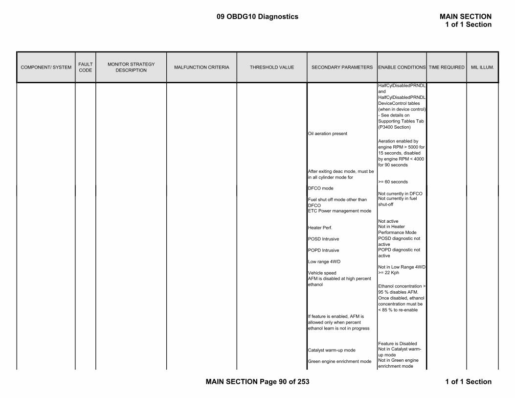
COMPONENT/ SYSTEM FAULT CODE
MONITOR STRATEGY DESCRIPTION MALFUNCTION CRITERIA THRESHOLD VALUE SECONDARY PARAMETERS ENABLE CONDITIONS TIME REQUIRED MIL ILLUM.
DFCO d
Oil aeration present
HalfCylDisabledPRNDL and HalfCylDisabledPRNDLDeviceControl tables (when in device control) - See details on Supporting Tables Tab (P3400 Section)
>= 60 seconds
After exiting deac mode, must be in all cylinder mode for
Aeration enabled by engine RPM > 5000 for 15 seconds, disabled by engine RPM < 4000 for 90 seconds
DFCO modeNot currently in DFCO
POSD Intrusive POSD diagnostic not active
POPD Intrusive POPD diagnostic not active
Low range 4WDNot in Low Range 4WD
Vehicle speed >= 22 Kph
Not currently in fuel shut-off
ETC Power management mode
Not active
Fuel shut off mode other than DFCO
Catalyst warm-up mode Not in Catalyst warm-up mode
AFM is disabled at high percent ethanol Ethanol concentration >
95 % disables AFM. Once disabled, ethanol concentration must be < 85 % to re-enable
If feature is enabled, AFM is allowed only when percent ethanol learn is not in progress
Feature is Disabled
Heater Perf. Not in Heater Performance Mode
Not in Green engine enrichment mode
Green engine enrichment mode
09 OBDG10 Diagnostics MAIN SECTION1 of 1 Section
MAIN SECTION Page 90 of 253 1 of 1 Section

COMPONENT/ SYSTEM FAULT CODE
MONITOR STRATEGY DESCRIPTION MALFUNCTION CRITERIA THRESHOLD VALUE SECONDARY PARAMETERS ENABLE CONDITIONS TIME REQUIRED MIL ILLUM.
Deac mode active >= 600 seconds
Delta vacuum > 5 kPa or < -5 kPa
Engine RPM >
OR
Delta calculated using 1st order vacuum lag filter
0.30 1st order lag filter value
then reactivation will occur if:
2-Mode Hybrid vehicles Hybrid module not requesting AFM disable
IF DEACTIVATED, ANY OF THE CONDITIONS BELOW WILL FORCE CYLINDER REACTIVATION
If deactivation mode is active for>= 480 seconds
Piston protection Active
Engine RPM > EngSpeedDisableLwrLimitTable AND < EngSpeedDisableUprLimitTable - Details on Supporting Tables Tab (P3400 Section)
Engine Power Limited ModeActive
In device control only, when in Park or Neutral, engine RPM
<= 8.0 KphTrans Gear
AllCylDisabledTransGr -
Aeration enabled by engine RPM > 5000 for 15 seconds, disabled by engine RPM < 4000 for 90 seconds
Oil aeration present
Engine Oil Pressure< 172 kPa or > 470 kPa
Engine Oil Temperature< 18 kPa or > 130 kPa
Engine Metal Overtemp Protection
Active
09 OBDG10 Diagnostics MAIN SECTION1 of 1 Section
MAIN SECTION Page 91 of 253 1 of 1 Section

COMPONENT/ SYSTEM FAULT CODE
MONITOR STRATEGY DESCRIPTION MALFUNCTION CRITERIA THRESHOLD VALUE SECONDARY PARAMETERS ENABLE CONDITIONS TIME REQUIRED MIL ILLUM.
Ignition voltage < 11.0 or > 18.0 VoltsEngine Coolant < 40.0 or > 128.0 Deg
CVehicle speed < 22.0 KPH
See details on Supporting Tables Tab (P3400 Section)
PRNDL state
HalfCylDisabledPRNDL and HalfCylDisabledPRNDLDeviceControl tables (when in device control) - See details on Supporting Tables Tab (P3400 Section)
Brake booster vacuum
Pct Throttle Area > 30 Percent
Piston protection ActiveHot Coolant Mode ActiveEngine running = False
Gear Shift In progress
Tip In Bump Active
Cat. Temp Low ActivePOSD Intrusive ActiveFWD In low rangeEngine Misfire Detected
POPD Intrusive Active
Filtered engine vacuum > HalfCylToAllCylVacuum - See details on Supporting Tables Tab (P3400 Section) for 0 sec.
ETC Power management mode
Active
Engine overspeed protection
Heater Performance
AC Clutch transition In progress
Engine Metal Overtemp ProtectActive
Active
Converter overtemp protect
Brake booster vacuum< 0.0 kPa
Active
Active
09 OBDG10 Diagnostics MAIN SECTION1 of 1 Section
MAIN SECTION Page 92 of 253 1 of 1 Section

COMPONENT/ SYSTEM FAULT CODE
MONITOR STRATEGY DESCRIPTION MALFUNCTION CRITERIA THRESHOLD VALUE SECONDARY PARAMETERS ENABLE CONDITIONS TIME REQUIRED MIL ILLUM.
Fault bundles:Map_SensorFAVehicleSpeedSensorErrorECT_Sensor_FAEOP_Sensor_FA
PowertrainRelayFault
BrakeBoosterSensorFACrankSensorFACamSensorFAIAT_SensorFACylnderDeacDriverTFTKOFourWheelDriveLowStateValidEngineTorqueEstInacc
t
No active DTC's
urateTransmissionGearDefaultedEnginePowerLimited
Engine RPM >= 400.0 RPM Type B2 trips
Ignition Voltage <= 18.0 and >= 11.0 Volts
Engine RPM >= 400.0 RPM Type B2 trips
Ignition Voltage <= 18.0 and >= 11.0 Volts
Engine RPM >= 400.0 RPM Type B2 trips
Ignition Voltage <= 18.0 and >= 11.0 Volts
Cylinder 1 Deactivation Solenoid Control Circuit
P3401 Checks the Solenoid Control Circuit electrical integrity for cylinder #1
The ECM detects that commanded state of driver and actual state of the control circuit do not match. (Short to ground, short to voltage, open circuit)
Enabled Performed every 250 msec
Diagnostic enabled/disabled
Cylinder 4 Deactivation Solenoid Control Circuit
P3425 Checks the Solenoid Control Circuit electrical integrity for cylinder #4
The ECM detects that commanded state of driver and actual state of the control circuit do not match. (Short to ground, short to voltage, open circuit)
20 failures out of 25 samples
Diagnostic enabled/disabledEnabled Performed every
250 msec
20 failures out of 25 samples
Diagnostic enabled/disabledEnabled
20 failures out of 25 samples
Performed every 250 msec
Cylinder 6 Deactivation Solenoid Control Circuit
P3441 Checks the Solenoid Control Circuit electrical integrity for cylinder #6
The ECM detects that commanded state of driver and actual state of the control circuit do not match. (Short to ground, short to voltage, open circuit)
09 OBDG10 Diagnostics MAIN SECTION1 of 1 Section
MAIN SECTION Page 93 of 253 1 of 1 Section

COMPONENT/ SYSTEM FAULT CODE
MONITOR STRATEGY DESCRIPTION MALFUNCTION CRITERIA THRESHOLD VALUE SECONDARY PARAMETERS ENABLE CONDITIONS TIME REQUIRED MIL ILLUM.
Engine RPM >= 400.0 RPM Type B2 trips
Ignition Voltage <= 18.0 and >= 11.0 Volts
This DTC monitors for a BUS A off condition Bus off failures
≥ 3 counts Bus off delay time ≥ 0.024999 seconds Diagnostic runs in 12.5 ms loop
Type A1 trip
out of these samples ≥ 5 counts
U0074Bus off failures
≥ 3 counts Type A1 trip
out of these samples ≥ 5 counts
Bus off delay time ≥ 0.1125 seconds Diagnostic runs in 12.5 ms loop
Control Module Communication Bus B Off
Detects that a CAN serial data bus shorted condition has occurred to force the CAN device driver to enter a bus-off state
Control Module Communication Bus A Off
U0073
Cylinder 7 Deactivation Solenoid Control Circuit
P3449 Checks the Solenoid Control Circuit electrical integrity for cylinder #7
The ECM detects that commanded state of driver and actual state of the control circuit do not match. (Short to ground, short to voltage, open circuit)
20 failures out of 25 samples
Diagnostic enabled/disabledEnabled Performed every
250 msec
U0101 Message is not received from controller for this many counts
>375 msec Run/Crank Voltage 11 volts ≤ Voltage ≤ 18 volts
6.25 msec loop Type A 1 trip
out of these samples Power mode is RUNCommunication bus is not OFF
or is typed as a C codeNormal Communication is enabledNormal Transmit capability is TRUEThe diagnostic system is not disabledThe bus has been on for > .025 seconds A message has been selected to
monitor.
Message is not received from controller for this many counts
> 750 msec Run/Crank Voltage 11 volts ≤ Voltage ≤ 18 volts
6.25 msec loop Type B2 trips
Power mode is RUNCommunication bus is not OFF
or is typed as a C codeNormal Communication is enabledNormal Transmit capability is TRUEThe diagnostic system is not disabled
Lost Communication with Transfer Case Control Module
Lost Communication With TCM
(Automatic Transmission)
Detects that CAN serial data communication has been lost with the TCM.
This DTC monitors for a loss of communication with the transfer case control module
U0102
09 OBDG10 Diagnostics MAIN SECTION1 of 1 Section
MAIN SECTION Page 94 of 253 1 of 1 Section

COMPONENT/ SYSTEM FAULT CODE
MONITOR STRATEGY DESCRIPTION MALFUNCTION CRITERIA THRESHOLD VALUE SECONDARY PARAMETERS ENABLE CONDITIONS TIME REQUIRED MIL ILLUM.
The bus has been on for > .025 seconds A message has been selected to
monitor.
This DTC monitors for a loss of communication with the fuel pump control module
Message is not received from controller for this many counts
> 500 msec Run/Crank Voltage 11 volts ≤ Voltage ≤ 18 volts
6.25 msec loop Type B2 trips
Power mode is RUNCommunication bus is not OFF
or is typed as a C codeNormal Communication is enabledNormal Transmit capability is TRUEThe diagnostic system is not disabledTh b h b f 025 d
U0109Lost Communication With Fuel Pump Control Module
The bus has been on for > .025 seconds A message has been selected to
monitor.
Message is not received from controller for this many counts
> 500 msec Run/Crank Voltage 11 volts ≤ Voltage ≤ 18 volts
6.25 msec loop Type B2 trips
Power mode is RUNCommunication bus is not OFF
or is typed as a C codeNormal Communication is enabledNormal Transmit capability is TRUEThe diagnostic system is not disabledThe bus has been on for > .025 seconds A message has been selected to
monitor.
Message is not received from controller for this many counts
> 500 msec Run/Crank Voltage 11 volts ≤ Voltage ≤ 18 volts
6.25 msec loop Type A 1 trip
Power mode is RUNCommunication bus is not OFF
or is typed as a C codeNormal Communication is enabledNormal Transmit capability is TRUE
Lost Communication With Brake System Control Module
Detects that CAN serial data communication has been lost with the Brake system control Module
Lost Communication With Hybrid Powertrain Control Module
U0293 Detects that CAN serial data communication has been lost with the HPCM
U0129
09 OBDG10 Diagnostics MAIN SECTION1 of 1 Section
MAIN SECTION Page 95 of 253 1 of 1 Section
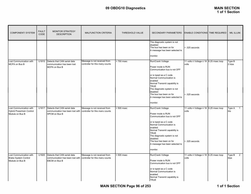
COMPONENT/ SYSTEM FAULT CODE
MONITOR STRATEGY DESCRIPTION MALFUNCTION CRITERIA THRESHOLD VALUE SECONDARY PARAMETERS ENABLE CONDITIONS TIME REQUIRED MIL ILLUM.
The diagnostic system is not disabledThe bus has been on for > .025 seconds A message has been selected to
monitor.
Message is not received from controller for this many counts
> 750 msec Run/Crank Voltage 11 volts ≤ Voltage ≤ 18 volts
6.25 msec loop Type B2 trips
Power mode is RUNCommunication bus is not OFF
or is typed as a C codeNormal Communication is enabledNormal Transmit capability is TRUEThe diagnostic system is not di bl d
Lost Communication with MCPA on Bus B
U1815 Detects that CAN serial data communication has been lost MCPA on Bus B
disabledThe bus has been on for > .025 seconds A message has been selected to
monitor.
Message is not received from controller for this many counts
> 500 msec Run/Crank Voltage 11 volts ≤ Voltage ≤ 18 volts
6.25 msec loop Type A 1 trip
Power mode is RUNCommunication bus is not OFF
or is typed as a C codeNormal Communication is enabledNormal Transmit capability is TRUEThe diagnostic system is not disabledThe bus has been on for > .025 seconds A message has been selected to
monitor.
Message is not received from controller for this many counts
> 500 msec Run/Crank Voltage 11 volts ≤ Voltage ≤ 18 volts
6.25 msec loop Type B 2 trips
Power mode is RUNCommunication bus is not OFF
or is typed as a C codeNormal Communication is enabledNormal Transmit capability is TRUE
Lost Communication with Brake System Control Module on Bus B
U1820 Detects that CAN serial data communication has been lost with EBCM on Bus B
Lost Communication with Hybrid Powertrain Control Module on Bus B
U1817 Detects that CAN serial data communication has been lost with HPCM on Bus B
09 OBDG10 Diagnostics MAIN SECTION1 of 1 Section
MAIN SECTION Page 96 of 253 1 of 1 Section
COMPONENT/ SYSTEM FAULT CODE
MONITOR STRATEGY DESCRIPTION MALFUNCTION CRITERIA THRESHOLD VALUE SECONDARY PARAMETERS ENABLE CONDITIONS TIME REQUIRED MIL ILLUM.
The diagnostic system is not disabledThe bus has been on for > .025 seconds A message has been selected to
monitor.
09 OBDG10 Diagnostics MAIN SECTION1 of 1 Section
MAIN SECTION Page 97 of 253 1 of 1 Section

P0442: EONV Pressure Threshold Table (in Pascals)
X axis is fuel level in %Y axis is temperature in deg C
0.0000 6.2499 12.4998 18.7497 24.9996 31.2495 37.4994 43.7493 49.9992 56.2491 62.4990 68.7490 74.9989 81.2488 87.4987 93.7486 99.9985-10.0000 -498.1810 -498.1810 -498.1810 -498.1810 -498.1810 -498.1810 -498.1810 -498.1810 -498.1810 -498.1810 -498.1810 -498.1810 -498.1810 -498.1810 -498.1810 -498.1810 -498.1810-4.3750 -498.1810 -498.1810 -498.1810 -498.1810 -498.1810 -498.1810 -498.1810 -498.1810 -498.1810 -498.1810 -498.1810 -498.1810 -498.1810 -498.1810 -498.1810 -498.1810 -498.18101.2500 -498.1810 -498.1810 -498.1810 -498.1810 -498.1810 -498.1810 -498.1810 -498.1810 -498.1810 -498.1810 -498.1810 -498.1810 -498.1810 -498.1810 -498.1810 -498.1810 -498.18106.8750 -498.1810 -498.1810 -498.1810 -498.1810 -498.1810 -498.1810 -498.1810 -498.1810 -498.1810 -498.1810 -498.1810 -498.1810 -498.1810 -498.1810 -498.1810 -498.1810 -498.1810
12.5000 -498.1810 -498.1810 -498.1810 -498.1810 -498.1810 -498.1810 -498.1810 -498.1810 -498.1810 -498.1810 -498.1810 -498.1810 -498.1810 -498.1810 -498.1810 -498.1810 -498.181018.1250 -498.1810 -498.1810 -498.1810 -498.1810 -498.1810 -498.1810 -498.1810 -498.1810 -498.1810 -498.1810 -498.1810 -498.1810 -498.1810 -498.1810 -498.1810 -498.1810 -498.181023.7500 -498.1810 -498.1810 -498.1810 -498.1810 -498.1810 -498.1810 -498.1810 -498.1810 -498.1810 -498.1810 -498.1810 -498.1810 -498.1810 -498.1810 -498.1810 -498.1810 -498.181029.3750 -498.1810 -498.1810 -498.1810 -498.1810 -498.1810 -498.1810 -498.1810 -498.1810 -498.1810 -498.1810 -498.1810 -498.1810 -498.1810 -498.1810 -498.1810 -498.1810 -498.181035.0000 -498.1810 -498.1810 -498.1810 -498.1810 -498.1810 -498.1810 -498.1810 -498.1810 -498.1810 -498.1810 -498.1810 -498.1810 -498.1810 -498.1810 -498.1810 -498.1810 -498.181040.6250 -498.1810 -498.1810 -498.1810 -498.1810 -498.1810 -498.1810 -498.1810 -498.1810 -498.1810 -498.1810 -498.1810 -498.1810 -498.1810 -498.1810 -498.1810 -498.1810 -498.181046.2500 -498.1810 -498.1810 -498.1810 -498.1810 -498.1810 -498.1810 -498.1810 -498.1810 -498.1810 -498.1810 -498.1810 -498.1810 -498.1810 -498.1810 -498.1810 -498.1810 -498.181051.8750 -498.1810 -498.1810 -498.1810 -498.1810 -498.1810 -498.1810 -498.1810 -498.1810 -498.1810 -498.1810 -498.1810 -498.1810 -498.1810 -498.1810 -498.1810 -498.1810 -498.181057.5000 -498.1810 -498.1810 -498.1810 -498.1810 -498.1810 -498.1810 -498.1810 -498.1810 -498.1810 -498.1810 -498.1810 -498.1810 -498.1810 -498.1810 -498.1810 -498.1810 -498.181063.1250 -498.1810 -498.1810 -498.1810 -498.1810 -498.1810 -498.1810 -498.1810 -498.1810 -498.1810 -498.1810 -498.1810 -498.1810 -498.1810 -498.1810 -498.1810 -498.1810 -498.181068.7500 -498.1810 -498.1810 -498.1810 -498.1810 -498.1810 -498.1810 -498.1810 -498.1810 -498.1810 -498.1810 -498.1810 -498.1810 -498.1810 -498.1810 -498.1810 -498.1810 -498.181074.3750 -498.1810 -498.1810 -498.1810 -498.1810 -498.1810 -498.1810 -498.1810 -498.1810 -498.1810 -498.1810 -498.1810 -498.1810 -498.1810 -498.1810 -498.1810 -498.1810 -498.181080.0000 -498.1810 -498.1810 -498.1810 -498.1810 -498.1810 -498.1810 -498.1810 -498.1810 -498.1810 -498.1810 -498.1810 -498.1810 -498.1810 -498.1810 -498.1810 -498.1810 -498.1810
P0442: Estimate of Ambient Temperature Valid Conditioning Time
EAT Valid Conditioning Time (in seconds)Axis is Ignition Off Time (in seconds)Axis Curve
0 300600 450
1200 5001800 6002400 6503000 6503600 6504200 6504800 6505400 6506000 6256600 6007200 5757800 5508400 5259000 5009600 480
10200 46010800 44011700 42012600 40013500 38014400 36015300 34016200 32017100 30018000 28019200 26020400 24021600 22022800 20024000 20025200 200
P0496: Purge Valve Leak Test Engine Vacuum Test Time (Cold Start) as a Function of Fuel Lev
Purge Valve Leak Test Engine Vacuum Test Time (in seconds)Axis is Fuel Level in %Axis Curve
0 55.46 53.9
12 52.419 50.925 49.431 47.937 46.444 44.950 43.456 42.062 40.569 39.075 37.581 36.187 34.694 33.1
100 31.6
P0326 Knock Detection Enabled Factors:
FastRtdMax: X - axis = Engine Speed (RPM)
ECM SUPPORTING TABLES
09 OBDG10 Diagnostics MAIN SECTION1 of 1 Section
MAIN SECTION Page 98 of 253 1 of 1 Section
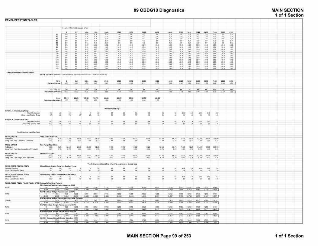
ECM SUPPORTING TABLES
Y - axis = Manifold Pressure (kPa)
0 512 1024 1536 2048 2560 3072 3584 4096 4608 5120 5632 6144 6656 7168 7680 819220 0.0 0.0 0.0 0.0 0.0 0.0 0.0 0.0 0.0 0.0 0.0 0.0 0.0 0.0 0.0 0.0 0.030 0.0 0.0 0.0 0.0 0.0 0.0 0.0 0.0 0.0 0.0 0.0 0.0 0.0 0.0 0.0 0.0 0.040 0.0 0.0 0.0 0.0 0.0 0.0 0.0 0.0 0.0 0.0 0.0 0.0 0.0 0.0 0.0 0.0 0.050 0.0 6.0 6.0 6.0 6.0 6.0 6.0 6.0 6.0 6.0 6.0 6.0 6.0 6.0 6.0 6.0 6.060 0.0 6.0 6.0 6.0 6.0 6.0 6.0 6.0 6.0 6.0 6.0 6.0 6.0 6.0 6.0 6.0 6.070 0.0 6.0 8.0 10.0 10.0 10.0 10.0 10.0 10.0 10.0 10.0 10.0 10.0 10.0 10.0 10.0 10.080 0.0 6.0 8.0 10.0 10.0 10.0 10.0 10.0 10.0 10.0 10.0 10.0 10.0 10.0 10.0 10.0 10.090 0.0 6.0 8.0 10.0 10.0 10.0 10.0 10.0 10.0 10.0 10.0 10.0 10.0 10.0 10.0 10.0 10.0100 0.0 6.0 8.0 10.0 10.0 10.0 10.0 10.0 10.0 10.0 10.0 10.0 10.0 10.0 10.0 10.0 10.0110 0.0 6.0 8.0 10.0 10.0 10.0 10.0 10.0 10.0 10.0 10.0 10.0 10.0 10.0 10.0 10.0 10.0120 0.0 6.0 8.0 10.0 10.0 10.0 10.0 10.0 10.0 10.0 10.0 10.0 10.0 10.0 10.0 10.0 10.0130 0.0 6.0 8.0 10.0 10.0 10.0 10.0 10.0 10.0 10.0 10.0 10.0 10.0 10.0 10.0 10.0 10.0140 0.0 6.0 8.0 10.0 10.0 10.0 10.0 10.0 10.0 10.0 10.0 10.0 10.0 10.0 10.0 10.0 10.0150 0.0 6.0 8.0 10.0 10.0 10.0 10.0 10.0 10.0 10.0 10.0 10.0 10.0 10.0 10.0 10.0 10.0160 0.0 6.0 8.0 10.0 10.0 10.0 10.0 10.0 10.0 10.0 10.0 10.0 10.0 10.0 10.0 10.0 10.0170 0.0 6.0 8.0 10.0 10.0 10.0 10.0 10.0 10.0 10.0 10.0 10.0 10.0 10.0 10.0 10.0 10.0180 0.0 6.0 8.0 10.0 10.0 10.0 10.0 10.0 10.0 10.0 10.0 10.0 10.0 10.0 10.0 10.0 10.0
Knock Detection Enabled Factors:Knock Detection Enabled = FastAttackRate * FastAttackCoolGain * FastAttackBaroGain
RPM: 0 512 1024 1536 2048 2560 3072 3584 4096 4608 5120 5632 6144 6656 7168 7680 8192FastAttackRate: 3.00 3.00 3.00 2.83 2.67 2.50 2.33 2.17 2.00 2.00 2.12 2.63 3.00 3.00 3.00 3.00 3.00
ECT (deg. C): -40 -30 -20 -10 0 10 20 30 40 50 60 70 80 90 100 110 120FastAttackCoolGain: 0.00 0.00 0.00 0.00 0.00 0.00 0.25 0.50 0.75 1.00 1.00 1.00 1.00 1.00 1.10 1.10 1.20
Baro: 55.00 61.25 67.50 73.75 80.00 86.25 92.50 98.75 105.00FastAttackBaroGain: 1.00 1.00 1.00 1.00 1.00 1.00 1.00 1.00 1.00
KtFSTA_T_ClosedLoopTempStart-Up Coolant -40 -28 -16 -4 8 20 32 44 56 68 80 92 104 116 128 140 152
Close Loop Enable Temp 85 80 75 65 45 39 39 39 39 39 39 39 39 39 39 39 39
KtFSTA_t_ClosedLoopTimeStart-Up Coolant -40 -28 -16 -4 8 20 32 44 56 68 80 92 104 116 128 140 152
Close Loop Enable Time 120 90 65 45 25 10 10 10 10 10 10 10 10 10 10 10 10
FASD Section_Ian MacEwen
P0171 & P0174 Long Term Trim Lean% Ethanol 0.00 6.25 12.50 18.75 25.00 31.25 37.50 43.75 50.00 56.25 62.50 68.75 75.00 81.25 87.50 93.75 100.00Long Term Fuel Trim Lean Threshold 1.33 1.33 1.33 1.33 1.33 1.33 1.33 1.33 1.33 1.33 1.33 1.33 1.33 1.33 1.33 1.33 1.33
P0172 & P0175 Non Purge Rich Limit% Ethanol 0.00 6.25 12.50 18.75 25.00 31.25 37.50 43.75 50.00 56.25 62.50 68.75 75.00 81.25 87.50 93.75 100.00Long Term Fuel Non-Purge Rich Threshold 0.70 0.70 0.70 0.70 0.70 0.70 0.70 0.70 0.70 0.70 0.70 0.70 0.70 0.70 0.70 0.70 0.70
P0172 & P0175 Purge Rich Limit% Ethanol 0.00 6.25 12.50 18.75 25.00 31.25 37.50 43.75 50.00 56.25 62.50 68.75 75.00 81.25 87.50 93.75 100.00Long Term Fuel Purge Rich Threshold 0.70 0.70 0.70 0.70 0.70 0.70 0.70 0.70 0.70 0.70 0.70 0.70 0.70 0.70 0.70 0.70 0.70
P0171, P0172, P0174 & P0175 Closed Loop Enable Temp vrs Coolant TempStart-Up Coolant -40 -28 -16 -4 8 20 32 44 56 68 80 92 104 116 128 140 152Close Loop Enable Temp 85 80 75 65 45 39 39 39 39 39 39 39 39 39 39 39 39
P0171, P0172, P0174 & P0175 Closed Loop Enable Time vrs Coolant TempStart-Up Coolant -40 -28 -16 -4 8 20 32 44 56 68 80 92 104 116 128 140 152Close Loop Enable Time 120 90 65 45 25 10 10 10 10 10 10 10 10 10 10 10 10
P0101, P0106, P0121, P012B, P1101: IFRD Residual Weighting FactorsTPS Residual Weight Factor based on RPM
RPM 0 250 750 1250 1750 2250 2750 3250 3750 4250 4750 5250 5750 6250 6750 7250 90001.000 1.000 1.000 1.000 1.000 1.000 1.000 1.000 1.000 1.000 0.993 0.629 0.566 0.519 0.519 0.519 0.519
MAF Residual Weight Factor based on RPMRPM 0 250 750 1250 1750 2250 2750 3250 3750 4250 4750 5250 5750 6250 6750 7250 9000
1.000 1.000 1.000 1.000 1.000 1.000 1.000 1.000 1.000 1.000 0.857 0.857 0.750 0.750 0.667 0.667 0.667MAF Residual Weight Factor Based on MAF Estimate
gm/sec 0.0 40.0 47.0 56.0 67.0 79.0 93.0 111.0 131.0 156.0 184.0 218.0 259.0 307.0 363.0 431.0 510.01.000 1.000 0.909 0.836 0.773 0.719 0.660 0.584 0.501 0.408 0.336 0.294 0.268 0.243 0.219 0.191 0.159
MAP1 Residual Weight Factor based on RPMRPM 0 250 750 1250 1750 2250 2750 3250 3750 4250 4750 5250 5750 6250 6750 7250 9000
0.625 0.625 1.000 1.000 1.000 1.000 1.000 1.000 1.000 0.417 0.417 0.417 0.417 0.417 0.417 0.417 0.417MAP2 Residual Weight Factor based on RPM
RPM 0 250 750 1250 1750 2250 2750 3250 3750 4250 4750 5250 5750 6250 6750 7250 90000.625 0.625 1.000 1.000 1.000 1.000 1.000 1.000 1.000 0.417 0.417 0.417 0.417 0.417 0.417 0.417 0.417
SCIAP1 Residual Weight Factor based on RPMRPM 0 1500 2200 2500 2800 3100 3200 3300 3500 3700 4000 4200 4500 5000 5500 6500 8000
1.000 1.000 1.000 1.000 1.000 1.000 1.000 1.000 1.000 1.000 1.000 1.000 1.000 1.000 1.000 1.000 1.000
Define Close Loop
The following tables define when the engine goes closed loop
09 OBDG10 Diagnostics MAIN SECTION1 of 1 Section
MAIN SECTION Page 99 of 253 1 of 1 Section

ECM SUPPORTING TABLES
SCIAP2 Residual Weight Factor based on RPMRPM 0 1500 2200 2500 2800 3100 3200 3300 3500 3700 4000 4200 4500 5000 5500 6500 8000
1.000 1.000 1.000 1.000 1.000 1.000 1.000 1.000 1.000 1.000 1.000 1.000 1.000 1.000 1.000 1.000 1.000Boost Residual Weight Factor based on % of Boost
% Boost 0.00 0.06 0.13 0.19 0.25 0.31 0.38 0.44 0.50 0.56 0.63 0.69 0.75 0.81 0.88 0.94 1.001.000 1.000 1.000 1.000 1.000 1.000 1.000 1.000 1.000 1.000 1.000 1.000 1.000 1.000 1.000 1.000 1.000
DTC Set TPS Model Failure
MAF Model Failure
MAP 1 Model Failure
MAP 2 Model Failure
SCIAP 1 Model Failure
SCIAP 2 Model Failure
No DTC F F F F F FNo DTC F F F F F TNo DTC F F F F T FP012B F F F F T T
No DTC F F F T F FP1101 F F F T F TP1101 F F F T T FP1101 F F F T T T
No DTC F F T F F FP1101 F F T F F TP1101 F F T F T FP1101 F F T F T TP0106 F F T T F FP1101 F F T T F TP1101 F F T T T FP1101 F F T T T T
No DTC F T F F F FP0101 F T F F F T
No DTC F T F F T FP0101, P012B F T F F T T
P1101 F T F T F FP0101 F T F T F TP1101 F T F T T F
P0101, P012B F T F T T TP1101 F T T F F FP1101 F T T F F TP1101 F T T F T FP1101 F T T F T TP1101 F T T T F FP1101 F T T T F TP1101 F T T T T FP1101 F T T T T TP0121 T F F F F F
No DTC T F F F F TP0121 T F F F T FP1101 T F F F T TP1101 T F F T F FP1101 T F F T F TP1101 T F F T T FP1101 T F F T T TP0121 T F T F F FP1101 T F T F F TP0121 T F T F T FP1101 T F T F T TP1101 T F T T F FP1101 T F T T F TP1101 T F T T T FP1101 T F T T T TP0121 T T F F F FP1101 T T F F F TP0121 T T F F T FP1101 T T F F T TP1101 T T F T F FP1101 T T F T F TP1101 T T F T T FP1101 T T F T T TP0121 T T T F F FP1101 T T T F F TP0121 T T T F T FP1101 T T T F T T
P0108, P012D: MAP/SCIAP Cold Run Time ThresholdX axis is Engine Coolant Temperature in Deg C
Temp -30 -15 0 15 301.5 1.2 0.8 0.5 0.0
P0116: Fail if power up ECT exceeds IAT by these valuesZ axis is the Fast Failure temp difference (° C)X axis is IAT Temperature at Power up (° C)
-40 -28 -16 -4 8 20 32 44 56 68 80 92 104 116 128 140 15265 55 45 35 25 25 25 25 25 25 15 15 15 15 15 15 15
P0128: Maximum Accumulated Airflow for IAT and Start-up ECT conditionsZ axis is the accumulated airflow failure threshold (grams)
Supercharger Intake Flow Rationality Diagnostic Failure Matrix
09 OBDG10 Diagnostics MAIN SECTION1 of 1 Section
MAIN SECTION Page 100 of 253 1 of 1 Section
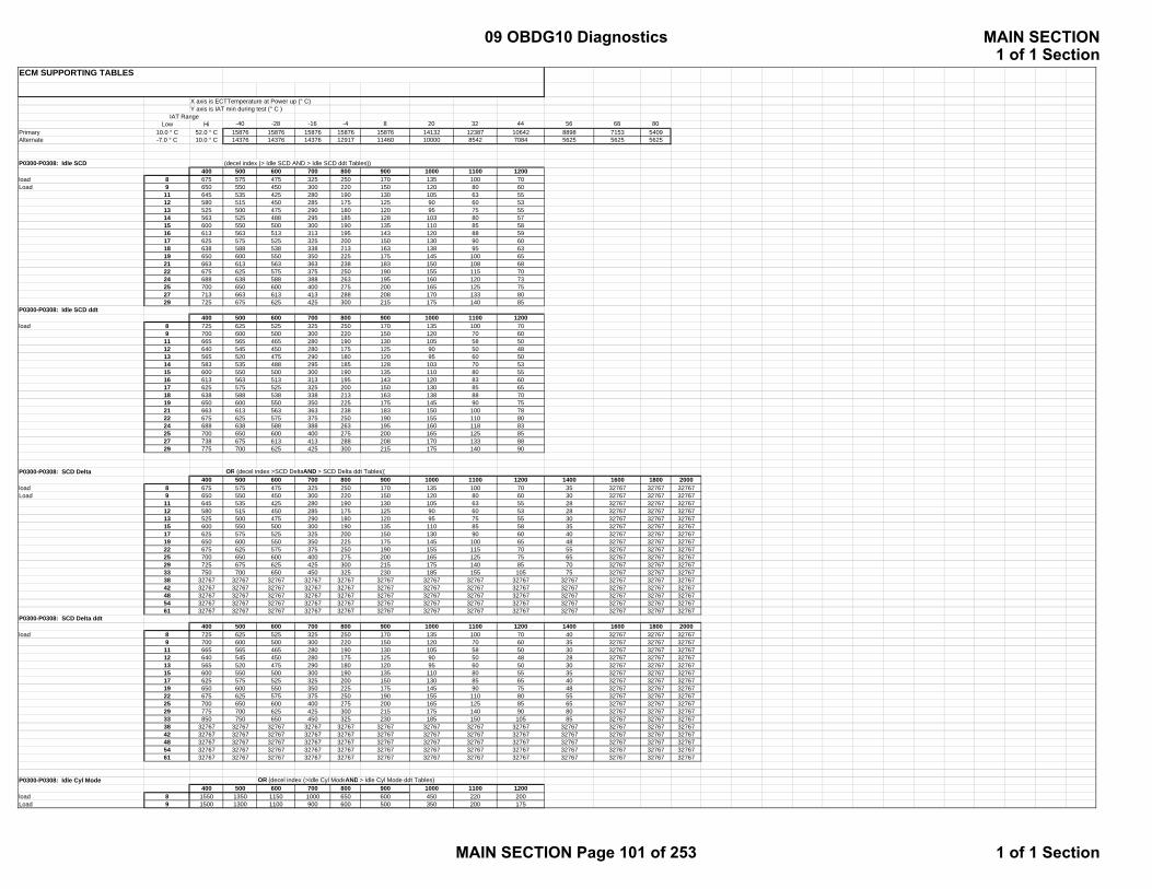
ECM SUPPORTING TABLES
X axis is ECTTemperature at Power up (° C)Y axis is IAT min during test (° C )
Low Hi -40 -28 -16 -4 8 20 32 44 56 68 80Primary 10.0 ° C 52.0 ° C 15876 15876 15876 15876 15876 14132 12387 10642 8898 7153 5409Alternate -7.0 ° C 10.0 ° C 14376 14376 14376 12917 11460 10000 8542 7084 5625 5625 5625
P0300-P0308: Idle SCD (decel index (> Idle SCD AND > Idle SCD ddt Tables))400 500 600 700 800 900 1000 1100 1200
load 8 675 575 475 325 250 170 135 100 70Load 9 650 550 450 300 220 150 120 80 60
11 645 535 425 280 190 130 105 63 5512 580 515 450 285 175 125 90 60 5313 525 500 475 290 180 120 95 75 5514 563 525 488 295 185 128 103 80 5715 600 550 500 300 190 135 110 85 5816 613 563 513 313 195 143 120 88 5917 625 575 525 325 200 150 130 90 6018 638 588 538 338 213 163 138 95 6319 650 600 550 350 225 175 145 100 6521 663 613 563 363 238 183 150 108 6822 675 625 575 375 250 190 155 115 7024 688 638 588 388 263 195 160 120 7325 700 650 600 400 275 200 165 125 7527 713 663 613 413 288 208 170 133 8029 725 675 625 425 300 215 175 140 85
P0300-P0308: Idle SCD ddt400 500 600 700 800 900 1000 1100 1200
load 8 725 625 525 325 250 170 135 100 709 700 600 500 300 220 150 120 70 6011 665 565 465 280 190 130 105 58 5012 640 545 450 280 175 125 90 50 4813 565 520 475 290 180 120 95 60 5014 583 535 488 295 185 128 103 70 5315 600 550 500 300 190 135 110 80 5516 613 563 513 313 195 143 120 83 6017 625 575 525 325 200 150 130 85 6518 638 588 538 338 213 163 138 88 7019 650 600 550 350 225 175 145 90 7521 663 613 563 363 238 183 150 100 7822 675 625 575 375 250 190 155 110 8024 688 638 588 388 263 195 160 118 8325 700 650 600 400 275 200 165 125 8527 738 675 613 413 288 208 170 133 8829 775 700 625 425 300 215 175 140 90
P0300-P0308: SCD Delta OR (decel index >SCD DeltaAND > SCD Delta ddt Tables))400 500 600 700 800 900 1000 1100 1200 1400 1600 1800 2000
load 8 675 575 475 325 250 170 135 100 70 35 32767 32767 32767Load 9 650 550 450 300 220 150 120 80 60 30 32767 32767 32767
11 645 535 425 280 190 130 105 63 55 28 32767 32767 3276712 580 515 450 285 175 125 90 60 53 28 32767 32767 3276713 525 500 475 290 180 120 95 75 55 30 32767 32767 3276715 600 550 500 300 190 135 110 85 58 35 32767 32767 3276717 625 575 525 325 200 150 130 90 60 40 32767 32767 3276719 650 600 550 350 225 175 145 100 65 48 32767 32767 3276722 675 625 575 375 250 190 155 115 70 55 32767 32767 3276725 700 650 600 400 275 200 165 125 75 65 32767 32767 3276729 725 675 625 425 300 215 175 140 85 70 32767 32767 3276733 750 700 650 450 325 230 185 155 105 75 32767 32767 3276738 32767 32767 32767 32767 32767 32767 32767 32767 32767 32767 32767 32767 3276742 32767 32767 32767 32767 32767 32767 32767 32767 32767 32767 32767 32767 3276748 32767 32767 32767 32767 32767 32767 32767 32767 32767 32767 32767 32767 3276754 32767 32767 32767 32767 32767 32767 32767 32767 32767 32767 32767 32767 3276761 32767 32767 32767 32767 32767 32767 32767 32767 32767 32767 32767 32767 32767
P0300-P0308: SCD Delta ddt400 500 600 700 800 900 1000 1100 1200 1400 1600 1800 2000
load 8 725 625 525 325 250 170 135 100 70 40 32767 32767 327679 700 600 500 300 220 150 120 70 60 35 32767 32767 3276711 665 565 465 280 190 130 105 58 50 30 32767 32767 3276712 640 545 450 280 175 125 90 50 48 28 32767 32767 3276713 565 520 475 290 180 120 95 60 50 30 32767 32767 3276715 600 550 500 300 190 135 110 80 55 35 32767 32767 3276717 625 575 525 325 200 150 130 85 65 40 32767 32767 3276719 650 600 550 350 225 175 145 90 75 48 32767 32767 3276722 675 625 575 375 250 190 155 110 80 55 32767 32767 3276725 700 650 600 400 275 200 165 125 85 65 32767 32767 3276729 775 700 625 425 300 215 175 140 90 80 32767 32767 3276733 850 750 650 450 325 230 185 150 105 85 32767 32767 3276738 32767 32767 32767 32767 32767 32767 32767 32767 32767 32767 32767 32767 3276742 32767 32767 32767 32767 32767 32767 32767 32767 32767 32767 32767 32767 3276748 32767 32767 32767 32767 32767 32767 32767 32767 32767 32767 32767 32767 3276754 32767 32767 32767 32767 32767 32767 32767 32767 32767 32767 32767 32767 3276761 32767 32767 32767 32767 32767 32767 32767 32767 32767 32767 32767 32767 32767
P0300-P0308: Idle Cyl Mode OR (decel index (>Idle Cyl ModeAND > Idle Cyl Mode ddt Tables)400 500 600 700 800 900 1000 1100 1200
load 8 1550 1350 1150 1000 650 600 450 220 200Load 9 1500 1300 1100 900 600 500 350 200 175
IAT Range
09 OBDG10 Diagnostics MAIN SECTION1 of 1 Section
MAIN SECTION Page 101 of 253 1 of 1 Section
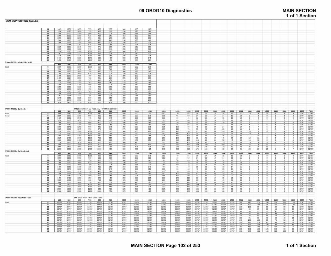
ECM SUPPORTING TABLES
11 1425 1250 1075 775 450 375 300 185 16512 1250 1150 1050 725 425 325 230 175 16013 1300 1200 1100 800 400 275 200 155 14514 1300 1225 1150 825 413 263 213 168 15315 1300 1250 1200 850 425 250 225 180 16016 1300 1263 1225 875 438 263 238 190 16817 1300 1275 1250 900 450 275 250 200 17518 1313 1288 1263 925 463 288 263 208 17819 1325 1300 1275 950 475 300 275 215 18021 1338 1313 1288 975 488 313 288 223 19022 1350 1325 1300 1000 500 325 300 230 20024 1363 1338 1313 1025 525 338 313 240 21325 1375 1350 1325 1050 550 350 325 250 22527 1413 1375 1338 1075 600 400 363 275 24529 1450 1400 1350 1100 650 450 400 300 265
P0300-P0308: Idle Cyl Mode ddt400 500 600 700 800 900 1000 1100 1200
load 8 1600 1350 1100 1000 650 600 580 200 1759 1550 1300 1050 900 600 500 350 180 15511 1500 1250 1000 750 450 375 300 165 14512 1300 1150 1000 625 425 325 230 160 12513 1400 1200 1000 700 400 275 200 135 12014 1400 1225 1050 713 405 263 205 148 13015 1400 1250 1100 725 410 250 210 160 14016 1375 1263 1150 763 418 263 218 170 14517 1350 1275 1200 800 425 275 225 180 15018 1350 1288 1225 775 438 288 238 190 15819 1350 1300 1250 750 450 300 250 200 16521 1350 1313 1275 763 463 313 263 205 17322 1350 1325 1300 775 475 325 275 210 18024 1363 1338 1313 788 488 338 288 218 19025 1375 1350 1325 800 500 350 300 225 20027 1413 1375 1338 825 563 400 325 263 21829 1450 1400 1350 850 625 450 350 300 235
P0300-P0308: Cyl Mode OR (decel index > Cyl Mode AND > Cyl Mode ddt Tables)400 500 600 700 800 900 1000 1100 1200 1400 1600 1800 2000 2200 2400 2600 2800 3000 3500 4000 4500 5000 5500 6000 6500 7000
load 8 1550 1350 1150 1000 650 600 450 220 200 110 70 55 36 21 18 15 13 11 10 9 9 9 9 9 32767 32767Load 9 1500 1300 1100 900 600 500 350 200 175 105 65 50 34 20 17 14 13 10 9 8 8 8 8 8 32767 32767
11 1425 1250 1075 775 450 375 300 185 165 100 60 45 32 22 18 15 11 10 8 8 8 8 8 8 32767 3276712 1250 1150 1050 725 425 325 230 175 160 95 65 40 33 25 18 15 11 10 8 7 7 7 7 7 32767 3276713 1300 1200 1100 800 400 275 200 155 145 100 70 50 35 33 25 18 14 12 7 7 7 6 6 6 32767 3276715 1300 1250 1200 850 425 250 225 180 160 115 85 55 43 35 28 21 16 13 8 7 6 6 6 6 32767 3276717 1300 1275 1250 900 450 275 250 200 175 125 105 70 48 38 30 24 19 14 8 7 6 5 5 5 32767 3276719 1325 1300 1275 950 475 300 275 215 180 155 110 75 55 40 32 26 21 16 9 8 6 5 5 5 32767 3276722 1350 1325 1300 1000 500 325 300 230 200 185 120 90 65 45 38 28 24 18 10 8 6 5 4 4 32767 3276725 1375 1350 1325 1050 550 350 325 250 225 210 140 100 75 55 45 33 26 20 10 9 7 5 4 4 32767 3276729 1450 1400 1350 1100 650 450 400 300 265 225 160 120 85 65 50 35 32 25 11 10 7 5 4 4 32767 3276733 1525 1450 1375 1150 750 550 450 400 325 250 180 130 90 75 60 45 35 28 13 11 8 5 5 4 32767 3276738 1600 1500 1400 1200 800 600 475 450 350 275 200 140 110 90 65 50 45 30 16 12 8 6 5 5 32767 3276742 1750 1600 1450 1250 850 625 500 475 375 300 225 160 120 95 70 55 50 33 19 14 9 6 6 5 32767 3276748 1900 1700 1500 1300 900 650 525 500 400 325 250 180 140 100 75 60 55 40 22 16 10 7 6 6 32767 3276754 2050 1800 1550 1350 950 700 550 525 425 350 275 200 150 105 80 70 60 43 25 18 11 7 7 6 32767 3276761 2200 1900 1600 1400 1000 750 600 550 425 375 300 220 175 110 90 80 65 45 28 20 13 9 8 7 32767 32767
P0300-P0308: Cyl Mode ddt400 500 600 700 800 900 1000 1100 1200 1400 1600 1800 2000 2200 2400 2600 2800 3000 3500 4000 4500 5000 5500 6000 6500 7000
load 8 1600 1350 1100 1000 650 600 580 200 175 115 70 55 36 24 19 15 13 12 0 0 0 0 0 0 32767 327679 1550 1300 1050 900 600 500 350 180 155 110 60 50 34 23 19 14 11 11 0 0 0 0 0 0 32767 3276711 1500 1250 1000 750 450 375 300 165 145 90 50 43 32 22 18 14 10 9 0 0 0 0 0 0 32767 3276712 1300 1150 1000 625 425 325 230 160 125 75 45 35 28 25 19 14 11 10 0 0 0 0 0 0 32767 3276713 1400 1200 1000 700 400 275 200 135 120 80 50 38 30 28 22 16 13 10 0 0 0 0 0 0 32767 3276715 1400 1250 1100 725 410 250 210 160 140 90 65 40 38 30 25 18 14 11 0 0 0 0 0 0 32767 3276717 1350 1275 1200 800 425 275 225 180 150 100 85 60 43 33 28 20 17 11 0 0 0 0 0 0 32767 3276719 1350 1300 1250 750 450 300 250 200 165 130 90 65 50 35 32 22 19 13 0 0 0 0 0 0 32767 3276722 1350 1325 1300 775 475 325 275 210 180 160 100 80 60 40 35 25 20 16 0 0 0 0 0 0 32767 3276725 1375 1350 1325 800 500 350 300 225 200 185 120 90 70 45 45 30 22 20 0 0 0 0 0 0 32767 3276729 1450 1400 1350 850 625 450 350 300 235 200 140 110 80 60 50 35 28 28 0 0 0 0 0 0 32767 3276733 1525 1450 1375 900 750 525 425 400 300 225 160 115 85 65 60 45 35 30 0 0 0 0 0 0 32767 3276738 1600 1500 1400 950 800 550 450 425 325 250 180 125 90 80 65 50 45 35 0 0 0 0 0 0 32767 3276742 1750 1600 1450 1000 850 600 475 450 350 275 200 140 100 85 70 55 50 38 0 0 0 0 0 0 32767 3276748 1900 1700 1500 1050 900 650 500 475 375 300 225 160 125 90 75 60 55 40 0 0 0 0 0 0 32767 3276754 2000 1800 1600 1100 950 700 525 500 400 325 250 180 135 95 80 70 60 43 0 0 0 0 0 0 32767 3276761 2100 1900 1700 1150 1000 750 575 525 425 350 275 200 150 100 90 80 65 45 0 0 0 0 0 0 32767 32767
P0300-P0308: Rev Mode Table OR (decel index > Rev Mode Table)400 500 600 700 800 900 1000 1100 1200 1400 1600 1800 2000 2200 2400 2600 2800 3000 3500 4000 4500 5000 5500 6000 6500 7000
load 8 32767 32767 32767 32767 32767 32767 32767 32767 32767 32767 32767 32767 32767 32767 32767 32767 32767 160 140 115 100 120 120 120 32767 327679 32767 32767 32767 32767 32767 32767 32767 32767 32767 32767 32767 32767 32767 32767 32767 32767 32767 145 120 100 75 100 100 100 32767 3276711 32767 32767 32767 32767 32767 32767 32767 32767 32767 32767 32767 32767 32767 32767 32767 32767 32767 130 100 90 55 80 80 80 32767 3276712 32767 32767 32767 32767 32767 32767 32767 32767 32767 32767 32767 32767 32767 32767 32767 32767 32767 120 90 85 50 50 55 60 32767 3276713 32767 32767 32767 32767 32767 32767 32767 32767 32767 32767 32767 32767 32767 32767 32767 32767 32767 95 80 75 55 42 42 40 32767 3276715 32767 32767 32767 32767 32767 32767 32767 32767 32767 32767 32767 32767 32767 32767 32767 32767 32767 90 85 65 60 40 40 35 32767 3276717 32767 32767 32767 32767 32767 32767 32767 32767 32767 32767 32767 32767 32767 32767 32767 32767 32767 100 88 80 65 50 35 30 32767 3276719 32767 32767 32767 32767 32767 32767 32767 32767 32767 32767 32767 32767 32767 32767 32767 32767 32767 150 95 90 70 60 40 35 32767 3276722 32767 32767 32767 32767 32767 32767 32767 32767 32767 32767 32767 32767 32767 32767 32767 32767 32767 170 105 100 80 70 50 40 32767 3276725 32767 32767 32767 32767 32767 32767 32767 32767 32767 32767 32767 32767 32767 32767 32767 32767 32767 190 115 110 90 80 60 50 32767 3276729 32767 32767 32767 32767 32767 32767 32767 32767 32767 32767 32767 32767 32767 32767 32767 32767 32767 225 125 120 100 90 70 60 32767 3276733 32767 32767 32767 32767 32767 32767 32767 32767 32767 32767 32767 32767 32767 32767 32767 32767 32767 250 140 130 110 100 80 70 32767 3276738 32767 32767 32767 32767 32767 32767 32767 32767 32767 32767 32767 32767 32767 32767 32767 32767 32767 300 170 140 125 110 90 80 32767 3276742 32767 32767 32767 32767 32767 32767 32767 32767 32767 32767 32767 32767 32767 32767 32767 32767 32767 350 200 160 140 120 100 90 32767 32767
09 OBDG10 Diagnostics MAIN SECTION1 of 1 Section
MAIN SECTION Page 102 of 253 1 of 1 Section
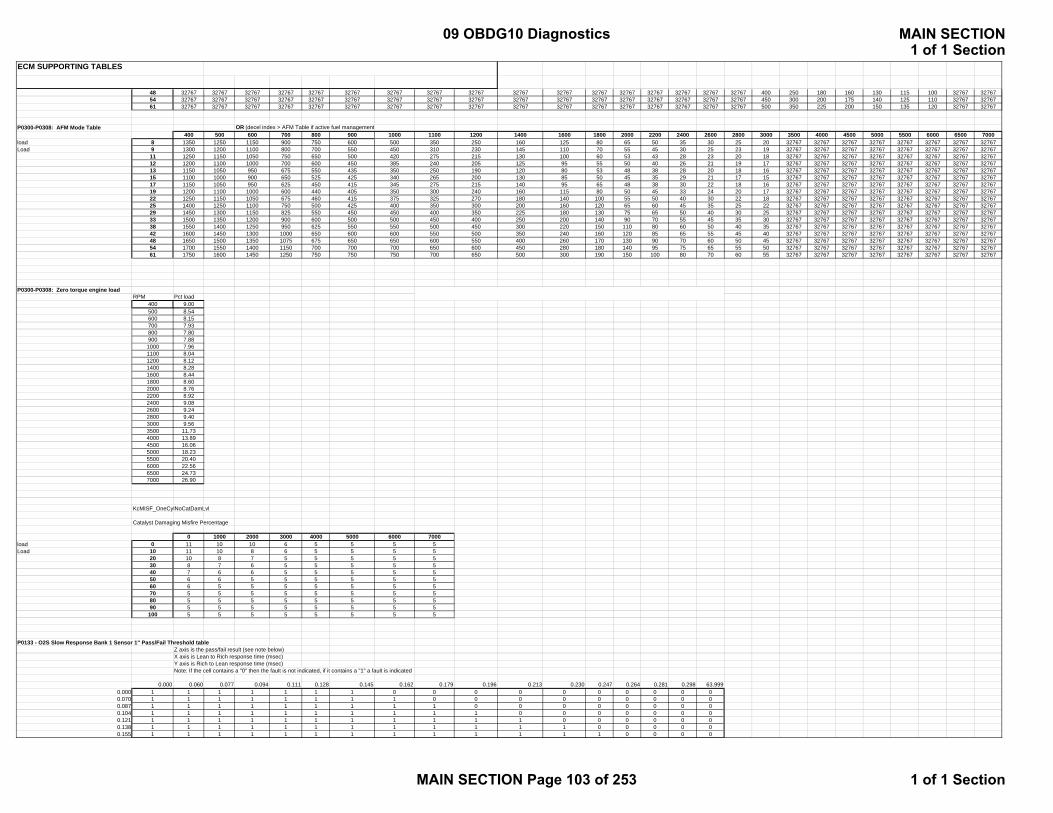
ECM SUPPORTING TABLES
48 32767 32767 32767 32767 32767 32767 32767 32767 32767 32767 32767 32767 32767 32767 32767 32767 32767 400 250 180 160 130 115 100 32767 3276754 32767 32767 32767 32767 32767 32767 32767 32767 32767 32767 32767 32767 32767 32767 32767 32767 32767 450 300 200 175 140 125 110 32767 3276761 32767 32767 32767 32767 32767 32767 32767 32767 32767 32767 32767 32767 32767 32767 32767 32767 32767 500 350 225 200 150 135 120 32767 32767
P0300-P0308: AFM Mode Table OR (decel index > AFM Table if active fuel management400 500 600 700 800 900 1000 1100 1200 1400 1600 1800 2000 2200 2400 2600 2800 3000 3500 4000 4500 5000 5500 6000 6500 7000
load 8 1350 1250 1150 900 750 600 500 350 250 160 125 80 65 50 35 30 25 20 32767 32767 32767 32767 32767 32767 32767 32767Load 9 1300 1200 1100 800 700 550 450 310 230 145 110 70 55 45 30 25 23 19 32767 32767 32767 32767 32767 32767 32767 32767
11 1250 1150 1050 750 650 500 420 275 215 130 100 60 53 43 28 23 20 18 32767 32767 32767 32767 32767 32767 32767 3276712 1200 1100 1000 700 600 450 385 240 205 125 95 55 50 40 26 21 19 17 32767 32767 32767 32767 32767 32767 32767 3276713 1150 1050 950 675 550 435 350 250 190 120 80 53 48 38 28 20 18 16 32767 32767 32767 32767 32767 32767 32767 3276715 1100 1000 900 650 525 425 340 265 200 130 85 50 45 35 29 21 17 15 32767 32767 32767 32767 32767 32767 32767 3276717 1150 1050 950 625 450 415 345 275 215 140 95 65 48 38 30 22 18 16 32767 32767 32767 32767 32767 32767 32767 3276719 1200 1100 1000 600 440 405 350 300 240 160 115 80 50 45 33 24 20 17 32767 32767 32767 32767 32767 32767 32767 3276722 1250 1150 1050 675 460 415 375 325 270 180 140 100 55 50 40 30 22 18 32767 32767 32767 32767 32767 32767 32767 3276725 1400 1250 1100 750 500 425 400 350 300 200 160 120 65 60 45 35 25 22 32767 32767 32767 32767 32767 32767 32767 3276729 1450 1300 1150 825 550 450 450 400 350 225 180 130 75 65 50 40 30 25 32767 32767 32767 32767 32767 32767 32767 3276733 1500 1350 1200 900 600 500 500 450 400 250 200 140 90 70 55 45 35 30 32767 32767 32767 32767 32767 32767 32767 3276738 1550 1400 1250 950 625 550 550 500 450 300 220 150 110 80 60 50 40 35 32767 32767 32767 32767 32767 32767 32767 3276742 1600 1450 1300 1000 650 600 600 550 500 350 240 160 120 85 65 55 45 40 32767 32767 32767 32767 32767 32767 32767 3276748 1650 1500 1350 1075 675 650 650 600 550 400 260 170 130 90 70 60 50 45 32767 32767 32767 32767 32767 32767 32767 3276754 1700 1550 1400 1150 700 700 700 650 600 450 280 180 140 95 75 65 55 50 32767 32767 32767 32767 32767 32767 32767 3276761 1750 1600 1450 1250 750 750 750 700 650 500 300 190 150 100 80 70 60 55 32767 32767 32767 32767 32767 32767 32767 32767
P0300-P0308: Zero torque engine loadRPM Pct load
400 9.00500 8.54600 8.15700 7.93800 7.80900 7.881000 7.961100 8.041200 8.121400 8.281600 8.441800 8.602000 8.762200 8.922400 9.082600 9.242800 9.403000 9.563500 11.734000 13.894500 16.065000 18.235500 20.406000 22.566500 24.737000 26.90
KcMISF_OneCylNoCatDamLvl
Catalyst Damaging Misfire Percentage
0 1000 2000 3000 4000 5000 6000 7000load 0 11 10 10 6 5 5 5 5Load 10 11 10 8 6 5 5 5 5
20 10 8 7 5 5 5 5 530 8 7 6 5 5 5 5 540 7 6 6 5 5 5 5 550 6 6 5 5 5 5 5 560 6 5 5 5 5 5 5 570 5 5 5 5 5 5 5 580 5 5 5 5 5 5 5 590 5 5 5 5 5 5 5 5
100 5 5 5 5 5 5 5 5
P0133 - O2S Slow Response Bank 1 Sensor 1" Pass/Fail Threshold tableZ axis is the pass/fail result (see note below)X axis is Lean to Rich response time (msec)Y axis is Rich to Lean response time (msec)Note: If the cell contains a "0" then the fault is not indicated, if it contains a "1" a fault is indicated
0.000 0.060 0.077 0.094 0.111 0.128 0.145 0.162 0.179 0.196 0.213 0.230 0.247 0.264 0.281 0.298 63.9990.000 1 1 1 1 1 1 1 0 0 0 0 0 0 0 0 0 00.070 1 1 1 1 1 1 1 1 0 0 0 0 0 0 0 0 00.087 1 1 1 1 1 1 1 1 1 0 0 0 0 0 0 0 00.104 1 1 1 1 1 1 1 1 1 1 0 0 0 0 0 0 00.121 1 1 1 1 1 1 1 1 1 1 1 0 0 0 0 0 00.138 1 1 1 1 1 1 1 1 1 1 1 1 0 0 0 0 00.155 1 1 1 1 1 1 1 1 1 1 1 1 1 0 0 0 0
09 OBDG10 Diagnostics MAIN SECTION1 of 1 Section
MAIN SECTION Page 103 of 253 1 of 1 Section

ECM SUPPORTING TABLES
0.172 1 1 1 1 1 1 1 1 1 1 1 1 1 1 0 0 00.189 1 1 1 1 1 1 1 1 1 1 1 1 1 1 1 0 00.206 0 1 1 1 1 1 1 1 1 1 1 1 1 1 1 1 00.223 0 0 1 1 1 1 1 1 1 1 1 1 1 1 1 1 00.240 0 0 0 1 1 1 1 1 1 1 1 1 1 1 1 1 00.257 0 0 0 0 1 1 1 1 1 1 1 1 1 1 1 1 00.274 0 0 0 0 0 1 1 1 1 1 1 1 1 1 1 1 00.291 0 0 0 0 0 0 1 1 1 1 1 1 1 1 1 1 00.308 0 0 0 0 0 0 0 1 1 1 1 1 1 1 1 1 0
63.999 0 0 0 0 0 0 0 0 0 0 0 0 0 0 0 0 0
P0153 - O2S Slow Response Bank 2 Sensor 1" Pass/Fail Threshold tableZ axis is the pass/fail result (see note below)X axis is Lean to Rich response time (msec)Y axis is Rich to Lean response time (msec)Note: If the cell contains a "0" then the fault is not indicated, if it contains a "1" a fault is indicated
0.000 0.060 0.077 0.094 0.111 0.128 0.145 0.162 0.179 0.196 0.213 0.230 0.247 0.264 0.281 0.298 63.9990.000 1 1 1 1 1 1 1 0 0 0 0 0 0 0 0 0 00.070 1 1 1 1 1 1 1 1 0 0 0 0 0 0 0 0 00.087 1 1 1 1 1 1 1 1 1 0 0 0 0 0 0 0 00.104 1 1 1 1 1 1 1 1 1 1 0 0 0 0 0 0 00.121 1 1 1 1 1 1 1 1 1 1 1 0 0 0 0 0 00.138 1 1 1 1 1 1 1 1 1 1 1 1 0 0 0 0 00.155 1 1 1 1 1 1 1 1 1 1 1 1 1 0 0 0 00.172 1 1 1 1 1 1 1 1 1 1 1 1 1 1 0 0 00.189 1 1 1 1 1 1 1 1 1 1 1 1 1 1 1 0 00.206 0 1 1 1 1 1 1 1 1 1 1 1 1 1 1 1 00.223 0 0 1 1 1 1 1 1 1 1 1 1 1 1 1 1 00.240 0 0 0 1 1 1 1 1 1 1 1 1 1 1 1 1 00.257 0 0 0 0 1 1 1 1 1 1 1 1 1 1 1 1 00.274 0 0 0 0 0 1 1 1 1 1 1 1 1 1 1 1 00.291 0 0 0 0 0 0 1 1 1 1 1 1 1 1 1 1 00.308 0 0 0 0 0 0 0 1 1 1 1 1 1 1 1 1 0
63.999 0 0 0 0 0 0 0 0 0 0 0 0 0 0 0 0 0
P1133 - O2S HC L to R Switches Limit Bank 1 Sensor 1" Pass/Fail Threshold tableZ axis is Limit for L/R HC switchesY axis is Average flow during the response test (gps)X axis is estimated Ethanol percentageNote: The cell contains the minumum switches
0.0 10.0 20.0 50.0 80.00.0 20 20 20 20 206.3 20 20 20 20 20
12.5 20 20 20 20 2018.8 20 20 20 20 2025.0 20 20 20 20 2031.3 20 20 20 20 2037.5 20 20 20 20 2043.8 20 20 20 20 2050.0 20 20 20 20 2056.3 20 20 20 20 2062.5 20 20 20 20 2068.8 20 20 20 20 2075.0 20 20 20 20 2081.3 20 20 20 20 2087.5 20 20 20 20 2093.8 20 20 20 20 20
100.0 20 20 20 20 20
P1133 - O2S HC R to L Switches Limit Bank 1 Sensor 1" Pass/Fail Threshold tableZ axis is Limit for R/L HC switchesY axis is Average flow during the response test (gps)X axis is estimated Ethanol percentageNote: The cell contains the minumum switches
0.0 10.0 20.0 50.0 80.00.0 20 20 20 20 206.3 20 20 20 20 20
12.5 20 20 20 20 2018.8 20 20 20 20 2025.0 20 20 20 20 2031.3 20 20 20 20 2037.5 20 20 20 20 2043.8 20 20 20 20 2050.0 20 20 20 20 2056.3 20 20 20 20 2062.5 20 20 20 20 2068.8 20 20 20 20 2075.0 20 20 20 20 2081.3 20 20 20 20 2087.5 20 20 20 20 2093.8 20 20 20 20 20
100.0 20 20 20 20 20
09 OBDG10 Diagnostics MAIN SECTION1 of 1 Section
MAIN SECTION Page 104 of 253 1 of 1 Section
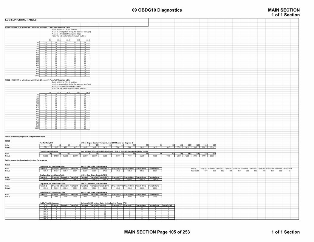
ECM SUPPORTING TABLES
P1153 - O2S HC L to R Switches Limit Bank 2 Sensor 1" Pass/Fail Threshold tableZ axis is Limit for L/R HC switchesY axis is Average flow during the response test (gps)X axis is estimated Ethanol percentageNote: The cell contains the minumum switches
0.0 10.0 20.0 50.0 80.00.0 20 20 20 20 206.3 20 20 20 20 20
12.5 20 20 20 20 2018.8 20 20 20 20 2025.0 20 20 20 20 2031.3 20 20 20 20 2037.5 20 20 20 20 2043.8 20 20 20 20 2050.0 20 20 20 20 2056.3 20 20 20 20 2062.5 20 20 20 20 2068.8 20 20 20 20 2075.0 20 20 20 20 2081.3 20 20 20 20 2087.5 20 20 20 20 2093.8 20 20 20 20 20
100.0 20 20 20 20 20
P1153 - O2S HC R to L Switches Limit Bank 2 Sensor 1" Pass/Fail Threshold tableZ axis is Limit for R/L HC switchesY axis is Average flow during the response test (gps)X axis is estimated Ethanol percentageNote: The cell contains the minumum switches
0.0 10.0 20.0 50.0 80.00.0 20 20 20 20 206.3 20 20 20 20 20
12.5 20 20 20 20 2018.8 20 20 20 20 2025.0 20 20 20 20 2031.3 20 20 20 20 2037.5 20 20 20 20 2043.8 20 20 20 20 2050.0 20 20 20 20 2056.3 20 20 20 20 2062.5 20 20 20 20 2068.8 20 20 20 20 2075.0 20 20 20 20 2081.3 20 20 20 20 2087.5 20 20 20 20 2093.8 20 20 20 20 20
100.0 20 20 20 20 20
Tables supporting Engine Oil Temperature Sensor
P0196FastFailTempDiff AXIS is Engine Coolant Temperature at ECM Power-up, Degrees C
Axis -40 -28 -16 -4 8 20 32 44 56 68 80 92 104 116 128 140 152Curve 75.0 60.0 45.0 30.0 30.0 30.0 30.0 30.0 30.0 30.0 30.0 30.0 30.0 30.0 30.0 30.0 30.0
TotalAccumulatedFlow Axis is Power up Engine Oil temperature, Curve is accumulated engine grams airflowAxis -40 -28 -16 -4 8 20 32 44 56 68 80 92 104 116 128 140 152Curve 15000 14000 13000 12000 11000 10000 9000 8000 7000 6000 5000 4000 5000 4000 3000 3000 3000
Tables supporting Deactivation System Performance
P3400EngSpeedLwrLimitEnableTable AXIS is Gear State, Curve is RPM
Axis TransGr1 TransGr2 TransGr3 TransGr4 TransGr5 TransGr6 TransGrEVT1 TransGrEVT2 TransGrNeut TransGrRvrs TransGrPark float x TransGr1 TransGr2 TransGr3 TransGr4 TransGr5 TransGr6 TransGrEVTransGrEVTransGrNeTransGrRvTransGrParkCurve 925.0 575.0 925.0 925.0 925.0 925.0 575.0 575.0 925.0 925.0 925.0 float 850.0 500 850 850 850 850 500 500 850 850 850 1
EngSpeedUprLimitEnableTable AXIS is Gear State, Curve is RPMAxis TransGr1 TransGr2 TransGr3 TransGr4 TransGr5 TransGr6 TransGrEVT1 TransGrEVT2 TransGrNeut TransGrRvrs TransGrParkCurve 2800.0 2800.0 2800.0 2800.0 2800.0 2800.0 2800.0 2800.0 2800.0 2800.0 2800.0
EngSpeedLwrLimitDisableTable AXIS is Gear State, Curve is RPMAxis TransGr1 TransGr2 TransGr3 TransGr4 TransGr5 TransGr6 TransGrEVT1 TransGrEVT2 TransGrNeut TransGrRvrs TransGrParkCurve 850.0 500.0 850.0 850.0 850.0 850.0 500.0 500.0 850.0 850.0 850.0
EngSpeedUprLimitDisableTable AXIS is Gear State, Curve is RPMAxis TransGr1 TransGr2 TransGr3 TransGr4 TransGr5 TransGr6 TransGrEVT1 TransGrEVT2 TransGrNeut TransGrRvrs TransGrParkCurve 3000 3000 3000 3000 3000 3000 3000 3000 3000 3000 3000
HalfCylToAllCylVacuum Horizontal AXIS is Gear State, Vertical axis is Engine RPMRPM TransGr1 TransGr2 TransGr3 TransGr4 TransGr5 TransGr6 TransGrEVT1 TransGrEVT2 TransGrNeut TransGrRvrs TransGrPark0.0 0 0 0 0 0 30 0 0 0 0 0
100.0 0 0 0 0 0 30 0 0 0 0 0200.0 0 0 0 0 0 30 0 0 0 0 0300.0 0 0 0 0 0 30 0 0 0 0 0400.0 0 0 0 0 0 30 0 0 0 0 0500.0 0 0 0 0 0 30 0 0 0 0 0
09 OBDG10 Diagnostics MAIN SECTION1 of 1 Section
MAIN SECTION Page 105 of 253 1 of 1 Section
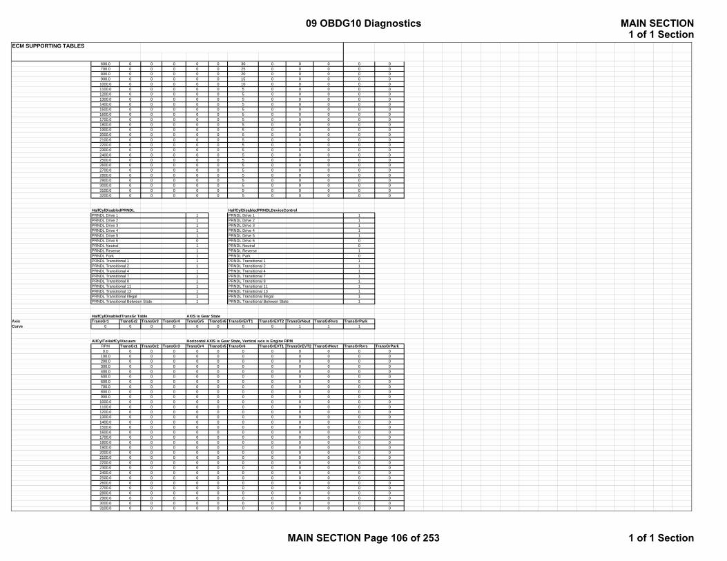
ECM SUPPORTING TABLES
600.0 0 0 0 0 0 30 0 0 0 0 0700.0 0 0 0 0 0 25 0 0 0 0 0800.0 0 0 0 0 0 20 0 0 0 0 0900.0 0 0 0 0 0 15 0 0 0 0 0
1000.0 0 0 0 0 0 10 0 0 0 0 01100.0 0 0 0 0 0 5 0 0 0 0 01200.0 0 0 0 0 0 5 0 0 0 0 01300.0 0 0 0 0 0 5 0 0 0 0 01400.0 0 0 0 0 0 5 0 0 0 0 01500.0 0 0 0 0 0 5 0 0 0 0 01600.0 0 0 0 0 0 5 0 0 0 0 01700.0 0 0 0 0 0 5 0 0 0 0 01800.0 0 0 0 0 0 5 0 0 0 0 01900.0 0 0 0 0 0 5 0 0 0 0 02000.0 0 0 0 0 0 5 0 0 0 0 02100.0 0 0 0 0 0 5 0 0 0 0 02200.0 0 0 0 0 0 5 0 0 0 0 02300.0 0 0 0 0 0 5 0 0 0 0 02400.0 0 0 0 0 0 5 0 0 0 0 02500.0 0 0 0 0 0 5 0 0 0 0 02600.0 0 0 0 0 0 5 0 0 0 0 02700.0 0 0 0 0 0 5 0 0 0 0 02800.0 0 0 0 0 0 5 0 0 0 0 02900.0 0 0 0 0 0 5 0 0 0 0 03000.0 0 0 0 0 0 5 0 0 0 0 03100.0 0 0 0 0 0 5 0 0 0 0 03200.0 0 0 0 0 0 5 0 0 0 0 0
HalfCylDisabledPRNDL HalfCylDisabledPRNDLDeviceControlPRNDL Drive 1 1 PRNDL Drive 1 1PRNDL Drive 2 1 PRNDL Drive 2 1PRNDL Drive 3 1 PRNDL Drive 3 1PRNDL Drive 4 1 PRNDL Drive 4 1PRNDL Drive 5 1 PRNDL Drive 5 1PRNDL Drive 6 0 PRNDL Drive 6 0PRNDL Neutral 1 PRNDL Neutral 0PRNDL Reverse 1 PRNDL Reverse 1PRNDL Park 1 PRNDL Park 0PRNDL Transitional 1 1 PRNDL Transitional 1 1PRNDL Transitional 2 1 PRNDL Transitional 2 1PRNDL Transitional 4 1 PRNDL Transitional 4 1PRNDL Transitional 7 1 PRNDL Transitional 7 1PRNDL Transitional 8 1 PRNDL Transitional 8 1PRNDL Transitional 11 1 PRNDL Transitional 11 1PRNDL Transitional 13 1 PRNDL Transitional 13 1PRNDL Transitional Illegal 1 PRNDL Transitional Illegal 1PRNDL Transitional Between State 1 PRNDL Transitional Between State 1
HalfCylDisabledTransGr Table AXIS is Gear StateAxis TransGr1 TransGr2 TransGr3 TransGr4 TransGr5 TransGr6 TransGrEVT1 TransGrEVT2 TransGrNeut TransGrRvrs TransGrParkCurve 0 0 0 0 0 0 0 0 1 1 1
AllCylToHalfCylVacuum Horizontal AXIS is Gear State, Vertical axis is Engine RPMRPM TransGr1 TransGr2 TransGr3 TransGr4 TransGr5 TransGr6 TransGrEVT1 TransGrEVT2 TransGrNeut TransGrRvrs TransGrPark0.0 0 0 0 0 0 0 0 0 0 0 0
100.0 0 0 0 0 0 0 0 0 0 0 0200.0 0 0 0 0 0 0 0 0 0 0 0300.0 0 0 0 0 0 0 0 0 0 0 0400.0 0 0 0 0 0 0 0 0 0 0 0500.0 0 0 0 0 0 0 0 0 0 0 0600.0 0 0 0 0 0 0 0 0 0 0 0700.0 0 0 0 0 0 0 0 0 0 0 0800.0 0 0 0 0 0 0 0 0 0 0 0900.0 0 0 0 0 0 0 0 0 0 0 0
1000.0 0 0 0 0 0 0 0 0 0 0 01100.0 0 0 0 0 0 0 0 0 0 0 01200.0 0 0 0 0 0 0 0 0 0 0 01300.0 0 0 0 0 0 0 0 0 0 0 01400.0 0 0 0 0 0 0 0 0 0 0 01500.0 0 0 0 0 0 0 0 0 0 0 01600.0 0 0 0 0 0 0 0 0 0 0 01700.0 0 0 0 0 0 0 0 0 0 0 01800.0 0 0 0 0 0 0 0 0 0 0 01900.0 0 0 0 0 0 0 0 0 0 0 02000.0 0 0 0 0 0 0 0 0 0 0 02100.0 0 0 0 0 0 0 0 0 0 0 02200.0 0 0 0 0 0 0 0 0 0 0 02300.0 0 0 0 0 0 0 0 0 0 0 02400.0 0 0 0 0 0 0 0 0 0 0 02500.0 0 0 0 0 0 0 0 0 0 0 02600.0 0 0 0 0 0 0 0 0 0 0 02700.0 0 0 0 0 0 0 0 0 0 0 02800.0 0 0 0 0 0 0 0 0 0 0 02900.0 0 0 0 0 0 0 0 0 0 0 03000.0 0 0 0 0 0 0 0 0 0 0 03100.0 0 0 0 0 0 0 0 0 0 0 0
09 OBDG10 Diagnostics MAIN SECTION1 of 1 Section
MAIN SECTION Page 106 of 253 1 of 1 Section

ECM SUPPORTING TABLES
3200.0 0 0 0 0 0 0 0 0 0 0 0
P0521
EngSpeedWeightFactorTable AXIS is Engine RPM, Curve is Weight FactorAxis 0 500 900 1000 2000 3000 4000 5000 6000Curve 0.0000 0.0000 0.0000 0.4500 0.4500 0.4500 0.4600 0.4400 0.0000
EngOilTempWeightFactorTable AXIS is Engine Oil Temp Deg C, Curve is Weight FactorAxis -40 40 60 80 90 100 120 130 140Curve 0.5780 0.7000 0.7000 0.7000 0.7000 0.7000 0.7000 0.7000 0.0000
EngLoadStabilityWeightFactorTable AXIS is Engine RPM, Curve is Weight FactorAxis 0 5 10 20 30 50 100 200 399Curve 0.9999 0.9999 0.5000 0.3000 0.0000 0.0000 0.0000 0.0000 0.0000
EngOilPredictionWeightFacotrTable AXIS is Engine RPM, Curve is Engine Oil Prediction Weight Factor RatioAxis 0 170 250 275 360 375 400 500 600Curve 0.0000 0.0000 0.1000 1.0000 1.0000 1.0000 1.0000 0.8600 0.0000
EGR SectionKtEGRD_p_StepDelta
X axis is Kpa BARO65 70 75 80 85 90 95 100 105
3.1953 3.1953 3.1953 3.1953 3.1953 3.1953 3.1953 3.1953 3.1953
KtEGRD_p_StepMAP_DIFFX axis is Kpa BARO
65 70 75 80 85 90 95 100 105-0.0391 -0.0391 -0.0391 -0.0391 -0.0391 -0.0391 -0.0391 -0.0391 -0.0391
KtEGRD_Cnt_StepSamplesPerTripX axis is Kpa BARO
65 70 75 80 85 90 95 100 1051.0000 1.0000 1.0000 1.0000 1.0000 1.0000 1.0000 1.0000 1.0000
KtEGRD_Cnt_SamplesAfterStepX axis is Kpa BARO
65 70 75 80 85 90 95 100 10510.0000 10.0000 10.0000 10.0000 10.0000 10.0000 10.0000 10.0000 10.0000
KtEGRD_Cnt_SamplesAfterResetX axis is Kpa BARO
65 70 75 80 85 90 95 100 10510.0000 10.0000 10.0000 10.0000 10.0000 10.0000 10.0000 10.0000 10.0000
Phaser SectionKtPHSD_phi_CamPosErrorLimIc1
X axis is Deg CY axis is RPM
-40.0000 -28.0000 -16.0000 -4.0000 8.0000 20.0000 32.0000 44.0000 56.0000 68.0000 80.0000 92.0000 104.0000 116.0000 128.0000 140.0000 152.0000400 13.0000 13.0000 10.0000 8.0000 8.0000 8.0000 8.0000 8.0000 8.0000 8.0000 8.0000 8.0000 8.0000 8.0000 8.0000 10.0000 10.0000800 13.0000 13.0000 10.0000 8.0000 8.0000 8.0000 8.0000 8.0000 8.0000 8.0000 8.0000 8.0000 8.0000 8.0000 8.0000 10.0000 10.0000
1200 13.0000 13.0000 10.0000 8.0000 8.0000 8.0000 8.0000 8.0000 8.0000 8.0000 8.0000 8.0000 8.0000 8.0000 8.0000 10.0000 10.00001600 13.0000 13.0000 10.0000 8.0000 8.0000 8.0000 8.0000 8.0000 8.0000 8.0000 8.0000 8.0000 8.0000 8.0000 8.0000 10.0000 10.00002000 13.0000 13.0000 10.0000 8.0000 8.0000 8.0000 8.0000 8.0000 8.0000 8.0000 8.0000 8.0000 8.0000 8.0000 8.0000 10.0000 10.00002400 13.0000 13.0000 10.0000 8.0000 8.0000 8.0000 8.0000 8.0000 8.0000 8.0000 8.0000 8.0000 8.0000 8.0000 8.0000 10.0000 10.00002800 13.0000 13.0000 10.0000 8.0000 8.0000 8.0000 8.0000 8.0000 8.0000 8.0000 8.0000 8.0000 8.0000 8.0000 8.0000 10.0000 10.00003200 13.0000 13.0000 10.0000 8.0000 8.0000 8.0000 8.0000 8.0000 8.0000 8.0000 8.0000 8.0000 8.0000 8.0000 8.0000 10.0000 10.00003600 13.0000 13.0000 10.0000 8.0000 8.0000 8.0000 8.0000 8.0000 8.0000 8.0000 8.0000 8.0000 8.0000 8.0000 8.0000 10.0000 10.00004000 13.0000 13.0000 10.0000 8.0000 8.0000 8.0000 8.0000 8.0000 8.0000 8.0000 8.0000 8.0000 8.0000 8.0000 8.0000 10.0000 10.00004400 13.0000 13.0000 10.0000 8.0000 8.0000 8.0000 8.0000 8.0000 8.0000 8.0000 8.0000 8.0000 8.0000 8.0000 8.0000 10.0000 10.00004800 13.0000 13.0000 10.0000 8.0000 8.0000 8.0000 8.0000 8.0000 8.0000 8.0000 8.0000 8.0000 8.0000 8.0000 8.0000 10.0000 10.00005200 13.0000 13.0000 10.0000 8.0000 8.0000 8.0000 8.0000 8.0000 8.0000 8.0000 8.0000 8.0000 8.0000 8.0000 8.0000 10.0000 10.00005600 13.0000 13.0000 10.0000 8.0000 8.0000 8.0000 8.0000 8.0000 8.0000 8.0000 8.0000 8.0000 8.0000 8.0000 8.0000 10.0000 10.00006000 13.0000 13.0000 10.0000 8.0000 8.0000 8.0000 8.0000 8.0000 8.0000 8.0000 8.0000 8.0000 8.0000 8.0000 8.0000 10.0000 10.00006400 13.0000 13.0000 10.0000 8.0000 8.0000 8.0000 8.0000 8.0000 8.0000 8.0000 8.0000 8.0000 8.0000 8.0000 8.0000 10.0000 10.00006800 13.0000 13.0000 10.0000 8.0000 8.0000 8.0000 8.0000 8.0000 8.0000 8.0000 8.0000 8.0000 8.0000 8.0000 8.0000 10.0000 10.0000
KtPHSD_t_StablePositionTimeIc1X axis is Deg CY axis is RPM
-40.0000 -28.0000 -16.0000 -4.0000 8.0000 20.0000 32.0000 44.0000 56.0000 68.0000 80.0000 92.0000 104.0000 116.0000 128.0000 140.0000 152.0000400 100.000 80.000 20.000 8.000 3.350 3.350 3.350 3.350 3.350 3.350 3.350 3.350 3.350 3.350 5.000 7.500 9.000800 100.000 80.000 20.000 8.000 3.350 3.350 3.350 3.350 3.350 3.350 3.350 3.350 3.350 3.350 5.000 7.500 9.000
1200 100.000 80.000 20.000 8.000 3.350 3.350 3.350 3.350 3.350 3.350 3.350 3.350 3.350 3.350 5.000 7.500 9.0001600 100.000 80.000 20.000 8.000 3.350 3.350 3.350 3.350 3.350 3.350 3.350 3.350 3.350 3.350 5.000 7.500 9.0002000 100.000 80.000 20.000 8.000 3.350 3.350 3.350 3.350 3.350 3.350 3.350 3.350 3.350 3.350 5.000 7.500 9.0002400 100.000 80.000 20.000 8.000 3.350 3.350 3.350 3.350 3.350 3.350 3.350 3.350 3.350 3.350 5.000 7.500 9.0002800 100.000 80.000 20.000 8.000 3.350 3.350 3.350 3.350 3.350 3.350 3.350 3.350 3.350 3.350 5.000 7.500 9.0003200 100.000 80.000 20.000 8.000 3.350 3.350 3.350 3.350 3.350 3.350 3.350 3.350 3.350 3.350 5.000 7.500 9.0003600 100.000 80.000 20.000 8.000 3.350 3.350 3.350 3.350 3.350 3.350 3.350 3.350 3.350 3.350 5.000 7.500 9.0004000 100.000 80.000 20.000 8.000 3.350 3.350 3.350 3.350 3.350 3.350 3.350 3.350 3.350 3.350 5.000 7.500 9.0004400 100.000 80.000 20.000 8.000 3.350 3.350 3.350 3.350 3.350 3.350 3.350 3.350 3.350 3.350 5.000 7.500 9.000
09 OBDG10 Diagnostics MAIN SECTION1 of 1 Section
MAIN SECTION Page 107 of 253 1 of 1 Section

ECM SUPPORTING TABLES
4800 100.000 80.000 20.000 8.000 3.350 3.350 3.350 3.350 3.350 3.350 3.350 3.350 3.350 3.350 5.000 7.500 9.0005200 100.000 80.000 20.000 8.000 3.350 3.350 3.350 3.350 3.350 3.350 3.350 3.350 3.350 3.350 5.000 7.500 9.0005600 100.000 80.000 20.000 8.000 3.350 3.350 3.350 3.350 3.350 3.350 3.350 3.350 3.350 3.350 5.000 7.500 9.0006000 100.000 80.000 20.000 8.000 3.350 3.350 3.350 3.350 3.350 3.350 3.350 3.350 3.350 3.350 5.000 7.500 9.0006400 100.000 80.000 20.000 8.000 3.350 3.350 3.350 3.350 3.350 3.350 3.350 3.350 3.350 3.350 5.000 7.500 9.0006800 100.000 80.000 20.000 8.000 3.350 3.350 3.350 3.350 3.350 3.350 3.350 3.350 3.350 3.350 5.000 7.500 9.000
P0068: MAP / MAF / TPS CorreleationX-axis is TPS (%)Data is MAP threshold (kPa)
X-axis 4.9988 9.9991 14.9994 19.9997 25.0000 29.9988 34.9991 39.9994 99.9985Data 29.7422 32.3594 32.5703 22.9531 17.9844 15.0234 100.0000 100.0000 100.0000
X axis is TPS (%)Data is MAF threshold (grams/sec)
X-axis 4.9988 9.9991 14.9994 19.9997 25.0000 29.9988 34.9991 39.9994 99.9985Data 27.7578 34.2500 41.0000 34.8359 36.0781 48.3594 255.0000 255.0000 255.0000
P1682: Ignition Voltage CorreleationX-axis is IAT (DegC)Data is Voltage threshold (V)
X-axis 23.0000 85.0000 95.0000 105.0000 125.0000Data 7.0000 8.6992 9.0000 9.1992 10.0000
P16F3: No fast unmanaged retarded spark above the applied sparkX-axis is ErpmY-axis is Air per Clyinder (mg)Data is spark delta threshold (kPa)
APC/Erpm 500.00 980.74 1461.48 1942.23 2422.97 2903.71 3384.45 3865.20 4345.94 4826.68 5307.42 5788.16 6268.91 6749.65 7230.39 7711.13 8191.8880.00 32.16 37.55 28.53 32.33 34.14 34.20 30.44 28.47 26.09 20.25 20.02 17.03 17.03 17.03 17.03 17.03 17.03
160.00 35.20 38.52 22.81 22.22 21.84 21.78 20.23 19.02 17.44 14.80 14.67 12.97 12.97 12.97 12.97 12.97 12.97240.00 38.86 39.16 19.77 15.89 15.42 15.22 14.64 14.55 13.41 11.94 11.80 10.63 10.63 10.63 10.63 10.63 10.63320.00 29.11 27.61 18.14 14.08 13.30 13.47 13.45 13.28 12.06 10.92 10.59 9.67 9.67 9.67 9.67 9.67 9.67400.00 19.59 17.23 17.38 12.77 12.23 12.83 13.27 12.77 11.31 10.23 9.78 9.05 9.05 9.05 9.05 9.05 9.05480.00 19.20 12.64 13.05 12.86 12.27 12.84 13.13 12.17 10.69 9.69 9.16 8.50 8.50 8.50 8.50 8.50 8.50560.00 33.19 13.23 9.94 9.83 11.56 13.11 12.83 11.50 10.13 9.20 8.53 7.84 7.84 7.84 7.84 7.84 7.84640.00 29.84 11.81 8.61 8.19 9.55 11.53 11.88 10.72 9.64 8.73 7.88 7.11 7.11 7.11 7.11 7.11 7.11720.00 52.58 11.83 8.33 6.78 7.39 7.78 8.73 8.88 8.52 7.59 7.00 6.48 6.48 6.48 6.48 6.48 6.48800.00 57.98 10.75 8.48 5.84 6.34 6.66 7.09 7.11 6.31 5.91 5.67 5.39 5.39 5.39 5.39 5.39 5.39880.00 64.64 9.86 7.80 5.34 5.83 6.02 6.61 6.52 5.78 5.41 5.20 4.89 4.89 4.89 4.89 4.89 4.89960.00 64.64 9.86 7.80 5.34 5.83 6.02 6.61 6.52 5.78 5.41 5.20 4.89 4.89 4.89 4.89 4.89 4.89
1040.00 64.64 9.86 7.80 5.34 5.83 6.02 6.61 6.52 5.78 5.41 5.20 4.89 4.89 4.89 4.89 4.89 4.891120.00 64.64 9.86 7.80 5.34 5.83 6.02 6.61 6.52 5.78 5.41 5.20 4.89 4.89 4.89 4.89 4.89 4.891200.00 64.64 9.86 7.80 5.34 5.83 6.02 6.61 6.52 5.78 5.41 5.20 4.89 4.89 4.89 4.89 4.89 4.891280.00 64.64 9.86 7.80 5.34 5.83 6.02 6.61 6.52 5.78 5.41 5.20 4.89 4.89 4.89 4.89 4.89 4.891360.00 64.64 9.86 7.80 5.34 5.83 6.02 6.61 6.52 5.78 5.41 5.20 4.89 4.89 4.89 4.89 4.89 4.89
P16F3: Absolute difference of redundant calculated engine speedX-axis is engine speed (rpm)Data is engine speed delta (rpm)
X-axis 0.0000 250.0000 500.0000 750.0000 1000.0000Data 1000.0000 750.0000 500.0000 300.0000 300.0000
P16F3: Absolute difference of the calculated Intake Manifold Pressure during engine event versus during time eventX-axis is engine torque (Nm)Data is MAP delta threshold (kPa)
X-axis 0.0000 50.0000 100.0000 150.0000 407.0000 408.0000Data 18.0000 18.0000 18.0000 18.0000 18.0000 255.0000
Transfer Case HIGH Ratio MarginX-axis is Veh Spd km/hrY-axis is Engine Torq N-mData is Ratio Margin
0.0 3.0 5.0 5.1 12.0 15.0 18.0 21.0 24.0-200 8.0 8.0 8.0 0.1 0.1 0.1 0.1 0.1 0.1-150 8.0 8.0 8.0 0.1 0.1 0.1 0.1 0.1 0.1-100 8.0 8.0 8.0 0.1 0.1 0.1 0.1 0.1 0.1-50 8.0 8.0 8.0 0.1 0.1 0.1 0.1 0.1 0.1
0 8.0 8.0 8.0 0.1 0.1 0.1 0.1 0.1 0.150 8.0 8.0 8.0 0.1 0.1 0.1 0.1 0.1 0.1
100 8.0 8.0 8.0 0.1 0.1 0.1 0.1 0.1 0.1150 8.0 8.0 8.0 0.1 0.1 0.1 0.1 0.1 0.1200 8.0 8.0 8.0 0.1 0.1 0.1 0.1 0.1 0.1
Transfer Case LOW Ratio MarginX-axis is Veh Spd km/hrY-axis is Engine Torq N-mData is Ratio Margin
0.0 3.0 5.0 5.1 12.0 15.0 18.0 21.0 24.0
KtSPRK_phi_DeltTorqueScrtyAdv
09 OBDG10 Diagnostics MAIN SECTION1 of 1 Section
MAIN SECTION Page 108 of 253 1 of 1 Section
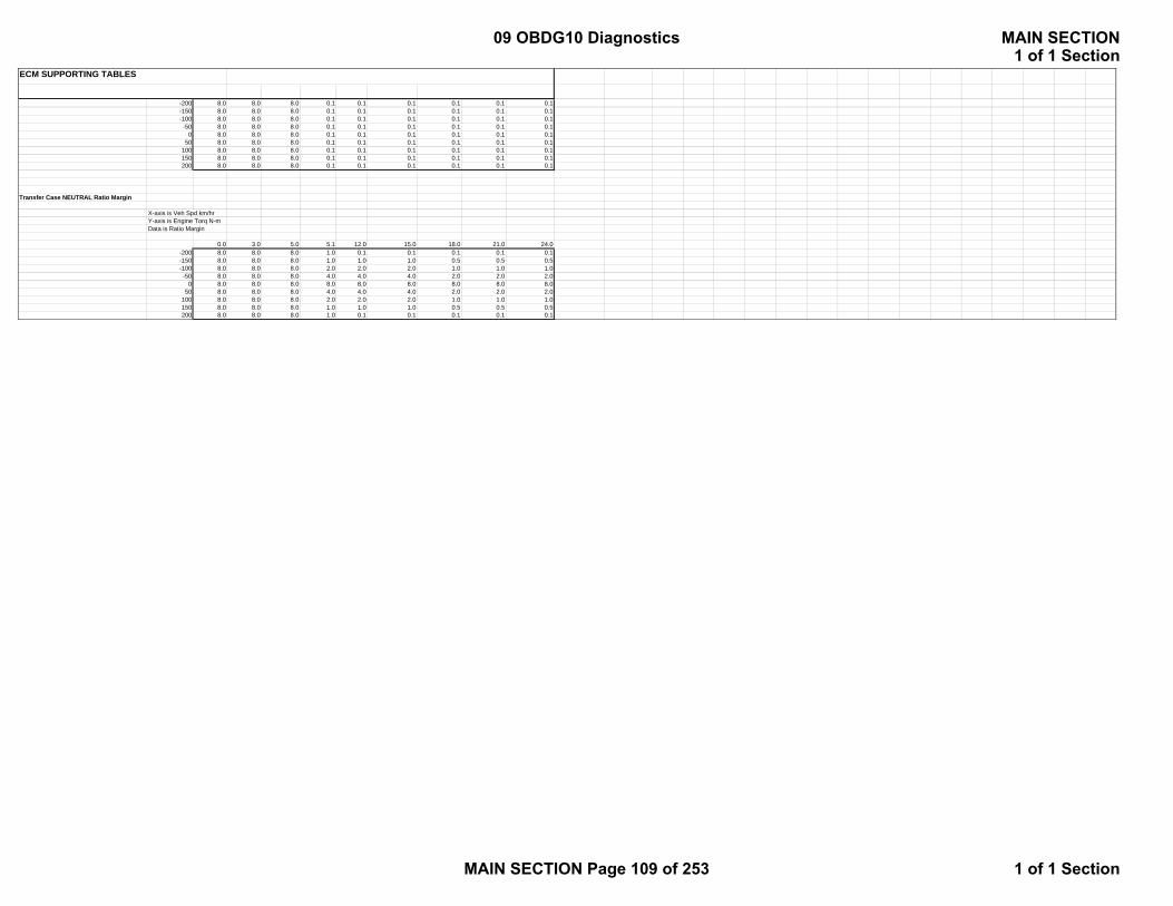
ECM SUPPORTING TABLES
-200 8.0 8.0 8.0 0.1 0.1 0.1 0.1 0.1 0.1-150 8.0 8.0 8.0 0.1 0.1 0.1 0.1 0.1 0.1-100 8.0 8.0 8.0 0.1 0.1 0.1 0.1 0.1 0.1-50 8.0 8.0 8.0 0.1 0.1 0.1 0.1 0.1 0.1
0 8.0 8.0 8.0 0.1 0.1 0.1 0.1 0.1 0.150 8.0 8.0 8.0 0.1 0.1 0.1 0.1 0.1 0.1
100 8.0 8.0 8.0 0.1 0.1 0.1 0.1 0.1 0.1150 8.0 8.0 8.0 0.1 0.1 0.1 0.1 0.1 0.1200 8.0 8.0 8.0 0.1 0.1 0.1 0.1 0.1 0.1
Transfer Case NEUTRAL Ratio Margin
X-axis is Veh Spd km/hrY-axis is Engine Torq N-mData is Ratio Margin
0.0 3.0 5.0 5.1 12.0 15.0 18.0 21.0 24.0-200 8.0 8.0 8.0 1.0 0.1 0.1 0.1 0.1 0.1-150 8.0 8.0 8.0 1.0 1.0 1.0 0.5 0.5 0.5-100 8.0 8.0 8.0 2.0 2.0 2.0 1.0 1.0 1.0-50 8.0 8.0 8.0 4.0 4.0 4.0 2.0 2.0 2.0
0 8.0 8.0 8.0 8.0 8.0 8.0 8.0 8.0 8.050 8.0 8.0 8.0 4.0 4.0 4.0 2.0 2.0 2.0
100 8.0 8.0 8.0 2.0 2.0 2.0 1.0 1.0 1.0150 8.0 8.0 8.0 1.0 1.0 1.0 0.5 0.5 0.5200 8.0 8.0 8.0 1.0 0.1 0.1 0.1 0.1 0.1
09 OBDG10 Diagnostics MAIN SECTION1 of 1 Section
MAIN SECTION Page 109 of 253 1 of 1 Section
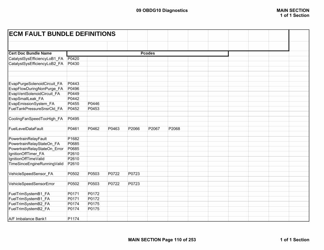
ECM FAULT BUNDLE DEFINITIONS
Cert Doc Bundle NameCatalystSysEfficiencyLoB1_FA P0420CatalystSysEfficiencyLoB2_FA P0430
EvapPurgeSolenoidCircuit_FA P0443EvapFlowDuringNonPurge_FA P0496EvapVentSolenoidCircuit_FA P0449EvapSmallLeak_FA P0442EvapEmissionSystem_FA P0455 P0446FuelTankPressureSnsrCkt_FA P0452 P0453
CoolingFanSpeedTooHigh_FA P0495
FuelLevelDataFault P0461 P0462 P0463 P2066 P2067 P2068
PowertrainRelayFault P1682PowertrainRelayStateOn_FA P0685PowertrainRelayStateOn_Error P0685IgnitionOffTimer_FA P2610IgnitionOffTimeValid P2610TimeSinceEngineRunningValid P2610
VehicleSpeedSensor_FA P0502 P0503 P0722 P0723
VehicleSpeedSensorError P0502 P0503 P0722 P0723
FuelTrimSystemB1_FA P0171 P0172FuelTrimSystemB1_FA P0171 P0172FuelTrimSystemB2_FA P0174 P0175FuelTrimSystemB2_FA P0174 P0175
A/F Imbalance Bank1 P1174
Pcodes
09 OBDG10 Diagnostics MAIN SECTION1 of 1 Section
MAIN SECTION Page 110 of 253 1 of 1 Section
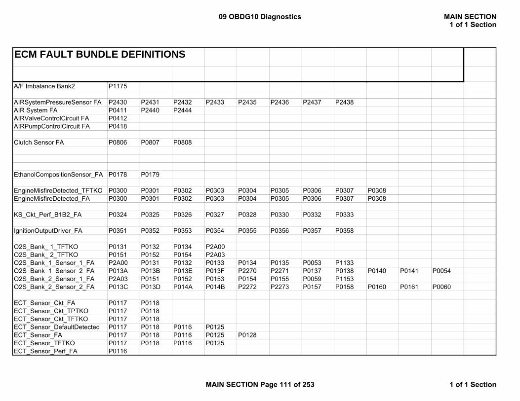
ECM FAULT BUNDLE DEFINITIONS
A/F Imbalance Bank2 P1175
AIRSystemPressureSensor FA P2430 P2431 P2432 P2433 P2435 P2436 P2437 P2438AIR System FA P0411 P2440 P2444AIRValveControlCircuit FA P0412AIRPumpControlCircuit FA P0418
Clutch Sensor FA P0806 P0807 P0808
EthanolCompositionSensor_FA P0178 P0179
EngineMisfireDetected_TFTKO P0300 P0301 P0302 P0303 P0304 P0305 P0306 P0307 P0308EngineMisfireDetected_FA P0300 P0301 P0302 P0303 P0304 P0305 P0306 P0307 P0308
KS_Ckt_Perf_B1B2_FA P0324 P0325 P0326 P0327 P0328 P0330 P0332 P0333
IgnitionOutputDriver_FA P0351 P0352 P0353 P0354 P0355 P0356 P0357 P0358
O2S_Bank_ 1_TFTKO P0131 P0132 P0134 P2A00O2S_Bank_ 2_TFTKO P0151 P0152 P0154 P2A03O2S_Bank_1_Sensor_1_FA P2A00 P0131 P0132 P0133 P0134 P0135 P0053 P1133O2S_Bank_1_Sensor_2_FA P013A P013B P013E P013F P2270 P2271 P0137 P0138 P0140 P0141 P0054O2S_Bank_2_Sensor_1_FA P2A03 P0151 P0152 P0153 P0154 P0155 P0059 P1153O2S_Bank_2_Sensor_2_FA P013C P013D P014A P014B P2272 P2273 P0157 P0158 P0160 P0161 P0060
ECT_Sensor_Ckt_FA P0117 P0118ECT_Sensor_Ckt_TPTKO P0117 P0118ECT_Sensor_Ckt_TFTKO P0117 P0118ECT_Sensor_DefaultDetected P0117 P0118 P0116 P0125ECT_Sensor_FA P0117 P0118 P0116 P0125 P0128ECT_Sensor_TFTKO P0117 P0118 P0116 P0125ECT_Sensor_Perf_FA P0116
09 OBDG10 Diagnostics MAIN SECTION1 of 1 Section
MAIN SECTION Page 111 of 253 1 of 1 Section
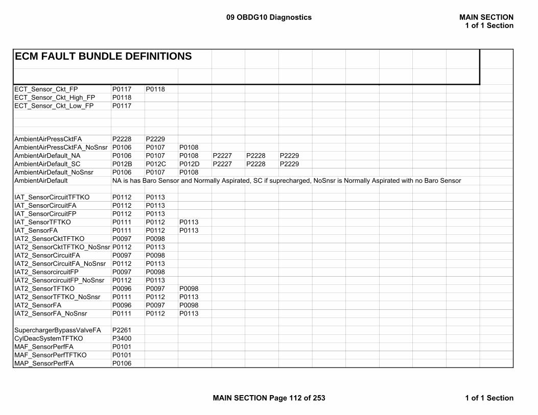
ECM FAULT BUNDLE DEFINITIONS
ECT_Sensor_Ckt_FP P0117 P0118ECT_Sensor_Ckt_High_FP P0118ECT_Sensor_Ckt_Low_FP P0117
AmbientAirPressCktFA P2228 P2229AmbientAirPressCktFA_NoSnsr P0106 P0107 P0108AmbientAirDefault_NA P0106 P0107 P0108 P2227 P2228 P2229AmbientAirDefault_SC P012B P012C P012D P2227 P2228 P2229AmbientAirDefault_NoSnsr P0106 P0107 P0108AmbientAirDefault NA is has Baro Sensor and Normally Aspirated, SC if suprecharged, NoSnsr is Normally Aspirated with no Baro Sensor
IAT_SensorCircuitTFTKO P0112 P0113IAT_SensorCircuitFA P0112 P0113IAT_SensorCircuitFP P0112 P0113IAT_SensorTFTKO P0111 P0112 P0113IAT_SensorFA P0111 P0112 P0113IAT2_SensorCktTFTKO P0097 P0098IAT2_SensorCktTFTKO_NoSnsr P0112 P0113IAT2_SensorCircuitFA P0097 P0098IAT2_SensorCircuitFA_NoSnsr P0112 P0113IAT2_SensorcircuitFP P0097 P0098IAT2_SensorcircuitFP_NoSnsr P0112 P0113IAT2_SensorTFTKO P0096 P0097 P0098IAT2_SensorTFTKO_NoSnsr P0111 P0112 P0113IAT2_SensorFA P0096 P0097 P0098IAT2_SensorFA_NoSnsr P0111 P0112 P0113
SuperchargerBypassValveFA P2261CylDeacSystemTFTKO P3400MAF_SensorPerfFA P0101MAF_SensorPerfTFTKO P0101MAP_SensorPerfFA P0106
09 OBDG10 Diagnostics MAIN SECTION1 of 1 Section
MAIN SECTION Page 112 of 253 1 of 1 Section

ECM FAULT BUNDLE DEFINITIONS
MAP_SensorPerfTFTKO P0106SCIAP_SensorPerfFA P012BSCIAP_SensorPerfTFTKO P012BThrottlePositionSnsrPerfFA P0121ThrottlePositionSnsrPerfTFTKO P0121
MAF_SensorFA P0101 P0102 P0103MAF_SensorTFTKO P0101 P0102 P0103MAF_SensorFP P0102 P0103MAF_SensorCircuitFA P0102 P0103MAF_SensorCircuitTFTKO P0102 P0103
MAP_SensorTFTKO P0106 P0107 P0108MAP_SensorFA P0106 P0107 P0108SCIAP_SensorFA P012B P012C P012DSCIAP_SensorTFTKO P012B P012C P012DSCIAP_SensorCircuitFP P012C P012DAfterThrottlePressureFA_NA P0106 P0107 P0108AfterThrottlePressureFA_SC P012B P012C P012DAfterThrottleVacuumTFTKO_NA P0106 P0107 P0108AfterThrottleVacuumTFTKO_SC P012B P012C P012DSCIAP_SensorCircuitFA P012C P012DAfterThrottlePressTFTKO_NA P0106 P0107 P0108AfterThrottlePressTFTKO_SC P012B P012C P012DMAP_SensorCircuitFA P0107 P0108MAP_EngineVacuumStatus MAP_SensorFA OR P0107, P0108 Pending
CrankCamCorrelationTFTKO P0016 P0017 P0018 P0019CrankSensorFA P0335 P0336CrankSensorTFTKO P0335 P0336CamSensorFA P0016 P0017 P0018 P0019 P0340 P0341 P0345 P0346 P0365 P0366 P0390 P0391CamSensorTFTKO P0016 P0017 P0018 P0019 P0340 P0341 P0345 P0346 P0365 P0366 P0390 P0391CrankIntakeCamCorrelationFA P0016 P0018CrankExhaustCamCorrelationFA P0017 P0019
09 OBDG10 Diagnostics MAIN SECTION1 of 1 Section
MAIN SECTION Page 113 of 253 1 of 1 Section

ECM FAULT BUNDLE DEFINITIONS
IntakeCamSensorTFTKO P0016 P0018 P0340 P0341 P0345 P0346IntakeCamSensorFA P0016 P0018 P0340 P0341 P0345 P0346ExhaustCamSensorTFTKO P0017 P0019 P0365 P0366 P0390 P0391ExhaustCamSensorFA P0017 P0019 P0365 P0366 P0390 P0391IntakeCamSensor_FA P0016 P0018 P0340 P0341 P0345 P0346IntakeCamSensor_TFTKO P0016 P0018 P0340 P0341 P0345 P0346ExhaustCamSensor_FA P0017 P0019 P0365 P0366 P0390 P0391ExhaustCamSensor_TFTKO P0017 P0019 P0365 P0366 P0390 P0391CrankIntakeCamCorrFA P0016 P0018CrankExhaustCamCorrFA P0017 P0019CrankSensorFaultActive P0335 P0336CrankSensor_FA P0335 P0336CrankSensorTestFailedTKO P0335 P0336CrankSensor_TFTKO P0335 P0336CamSensor_FA P0016 P0017 P0018 P0019 P0340 P0341 P0345 P0346 P0365 P0366 P0390 P0391CamSensorAnyLocationFA P0016 P0017 P0018 P0019 P0340 P0341 P0345 P0346 P0365 P0366 P0390 P0391CamSensor_TFTKO P0016 P0017 P0018 P0019 P0340 P0341 P0345 P0346 P0365 P0366 P0390 P0391
AnyCamPhaser_FA P0010 P0011 P0013 P0014 P0020 P0021 P0023 P0024AnyCamPhaser_TFTKO P0010 P0011 P0013 P0014 P0020 P0021 P0023 P0024IntkCamPhaser_FA P0010 P0011 P0020 P0021
EGRValvePerformance_FA P0401 P042EEGRValveCircuit_FA P0403 P0404 P0405 P0406EGRValve_FP P0405 P0406 P042EEGRValveCircuit_TFTKO P0403 P0404 P0405 P0406EGRValvePerformance_TFTKO P0401 P042E
EngineMetalOvertempActive P1258
no codes?
A/C_FailedOn P0645
09 OBDG10 Diagnostics MAIN SECTION1 of 1 Section
MAIN SECTION Page 114 of 253 1 of 1 Section
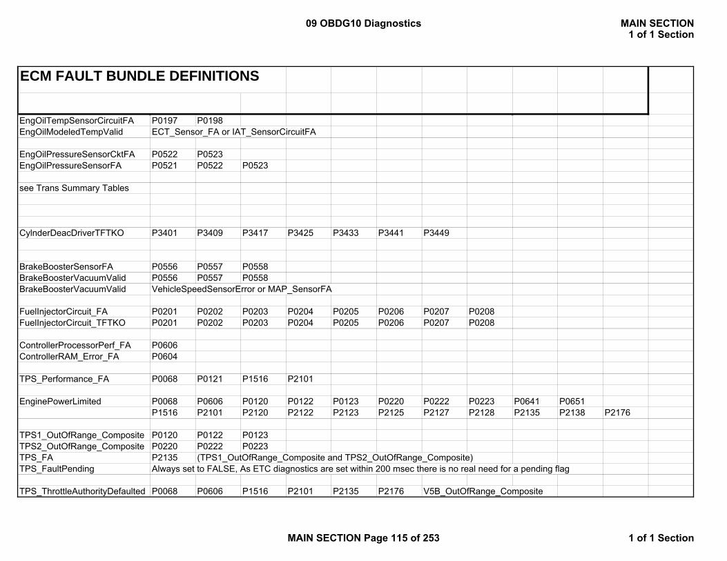
ECM FAULT BUNDLE DEFINITIONS
EngOilTempSensorCircuitFA P0197 P0198EngOilModeledTempValid ECT_Sensor_FA or IAT_SensorCircuitFA
EngOilPressureSensorCktFA P0522 P0523EngOilPressureSensorFA P0521 P0522 P0523
see Trans Summary Tables
CylnderDeacDriverTFTKO P3401 P3409 P3417 P3425 P3433 P3441 P3449
BrakeBoosterSensorFA P0556 P0557 P0558BrakeBoosterVacuumValid P0556 P0557 P0558BrakeBoosterVacuumValid VehicleSpeedSensorError or MAP_SensorFA
FuelInjectorCircuit_FA P0201 P0202 P0203 P0204 P0205 P0206 P0207 P0208FuelInjectorCircuit_TFTKO P0201 P0202 P0203 P0204 P0205 P0206 P0207 P0208
ControllerProcessorPerf_FA P0606ControllerRAM_Error_FA P0604
TPS_Performance_FA P0068 P0121 P1516 P2101
EnginePowerLimited P0068 P0606 P0120 P0122 P0123 P0220 P0222 P0223 P0641 P0651P1516 P2101 P2120 P2122 P2123 P2125 P2127 P2128 P2135 P2138 P2176
TPS1_OutOfRange_Composite P0120 P0122 P0123TPS2_OutOfRange_Composite P0220 P0222 P0223TPS_FA P2135 (TPS1_OutOfRange_Composite and TPS2_OutOfRange_Composite)TPS_FaultPending Always set to FALSE, As ETC diagnostics are set within 200 msec there is no real need for a pending flag
TPS_ThrottleAuthorityDefaulted P0068 P0606 P1516 P2101 P2135 P2176 V5B_OutOfRange_Composite
09 OBDG10 Diagnostics MAIN SECTION1 of 1 Section
MAIN SECTION Page 115 of 253 1 of 1 Section
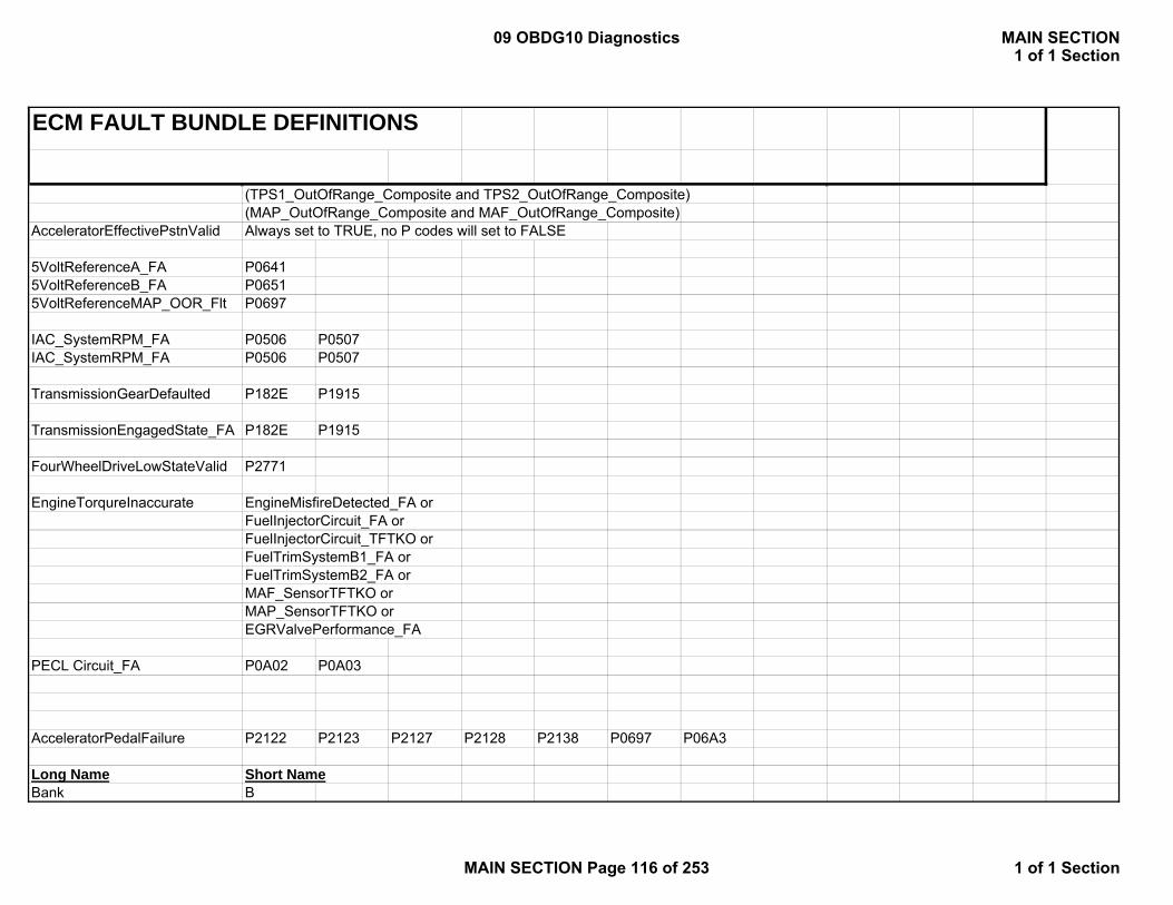
ECM FAULT BUNDLE DEFINITIONS
(TPS1_OutOfRange_Composite and TPS2_OutOfRange_Composite)(MAP_OutOfRange_Composite and MAF_OutOfRange_Composite)
AcceleratorEffectivePstnValid Always set to TRUE, no P codes will set to FALSE
5VoltReferenceA_FA P06415VoltReferenceB_FA P06515VoltReferenceMAP_OOR_Flt P0697
IAC_SystemRPM_FA P0506 P0507IAC_SystemRPM_FA P0506 P0507
TransmissionGearDefaulted P182E P1915
TransmissionEngagedState_FA P182E P1915
FourWheelDriveLowStateValid P2771
EngineTorqureInaccurate EngineMisfireDetected_FA orFuelInjectorCircuit_FA orFuelInjectorCircuit_TFTKO orFuelTrimSystemB1_FA orFuelTrimSystemB2_FA orMAF_SensorTFTKO orMAP_SensorTFTKO orEGRValvePerformance_FA
PECL Circuit_FA P0A02 P0A03
AcceleratorPedalFailure P2122 P2123 P2127 P2128 P2138 P0697 P06A3
Long Name Short NameBank B
09 OBDG10 Diagnostics MAIN SECTION1 of 1 Section
MAIN SECTION Page 116 of 253 1 of 1 Section
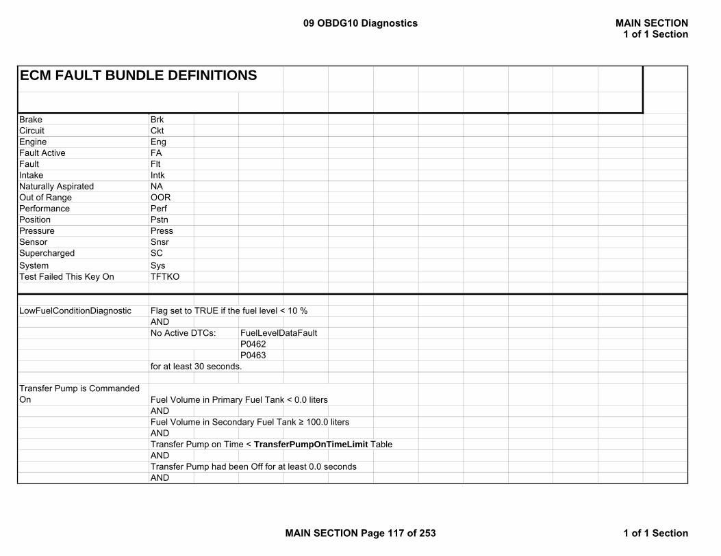
ECM FAULT BUNDLE DEFINITIONS
Brake BrkCircuit CktEngine EngFault Active FAFault FltIntake IntkNaturally Aspirated NAOut of Range OORPerformance PerfPosition PstnPressure PressSensor SnsrSupercharged SCSystem SysTest Failed This Key On TFTKO
LowFuelConditionDiagnosticAND
FuelLevelDataFaultP0462P0463
Transfer Pump is Commanded On Fuel Volume in Primary Fuel Tank < 0.0 liters
ANDFuel Volume in Secondary Fuel Tank ≥ 100.0 litersANDTransfer Pump on Time < TransferPumpOnTimeLimit TableANDTransfer Pump had been Off for at least 0.0 secondsAND
Flag set to TRUE if the fuel level < 10 %
No Active DTCs:
for at least 30 seconds.
09 OBDG10 Diagnostics MAIN SECTION1 of 1 Section
MAIN SECTION Page 117 of 253 1 of 1 Section
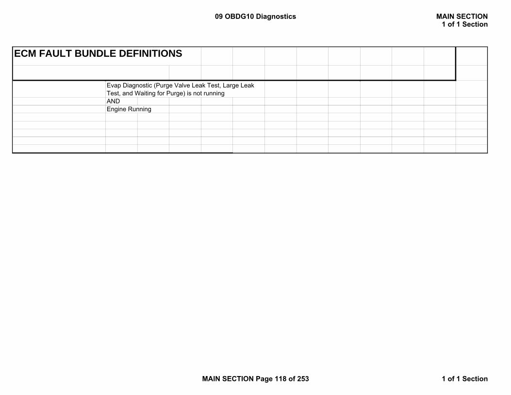
ECM FAULT BUNDLE DEFINITIONS
ANDEngine Running
Evap Diagnostic (Purge Valve Leak Test, Large Leak Test, and Waiting for Purge) is not running
09 OBDG10 Diagnostics MAIN SECTION1 of 1 Section
MAIN SECTION Page 118 of 253 1 of 1 Section
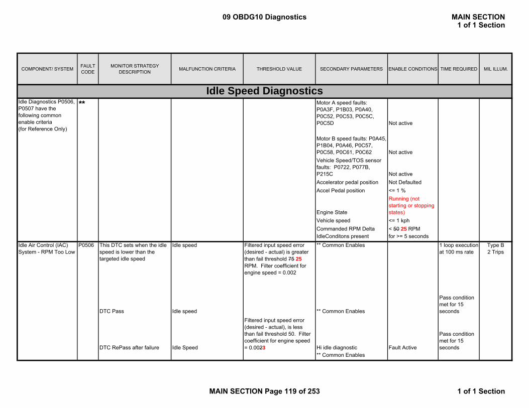
COMPONENT/ SYSTEM FAULT CODE
MONITOR STRATEGY DESCRIPTION MALFUNCTION CRITERIA THRESHOLD VALUE SECONDARY PARAMETERS ENABLE CONDITIONS TIME REQUIRED MIL ILLUM.
Motor A speed faults: P0A3F, P1B03, P0A40, P0C52, P0C53, P0C5C, P0C5D Not active
Motor B speed faults: P0A45, P1B04, P0A46, P0C57, P0C58, P0C61, P0C62 Not activeVehicle Speed/TOS sensor faults: P0722, P077B, P215C Not activeAccelerator pedal position Not DefaultedAccel Pedal position <= 1 %
Engine State
Running (not starting or stopping states)
Vehicle speed <= 1 kphCommanded RPM Delta < 50 25 RPMIdleConditons present for >= 5 seconds
This DTC sets when the idle speed is lower than the targeted idle speed
Idle speed Filtered input speed error (desired - actual) is greater than fail threshold 75 25 RPM. Filter coefficient for engine speed = 0.002
** Common Enables 1 loop execution at 100 ms rate
DTC Pass Idle speed ** Common Enables
Pass condition met for 15 seconds
DTC RePass after failure Idle Speed
Filtered input speed error (desired - actual), is less than fail threshold 50. Filter coefficient for engine speed = 0.0023 Hi idle diagnostic Fault Active
Pass condition met for 15 seconds
** Common Enables
P0506 Type B 2 Trips
**Idle Speed Diagnostics
Idle Diagnostics P0506, P0507 have the following common enable criteria (for Reference Only)
Idle Air Control (IAC) System - RPM Too Low
09 OBDG10 Diagnostics MAIN SECTION1 of 1 Section
MAIN SECTION Page 119 of 253 1 of 1 Section

COMPONENT/ SYSTEM FAULT CODE
MONITOR STRATEGY DESCRIPTION MALFUNCTION CRITERIA THRESHOLD VALUE SECONDARY PARAMETERS ENABLE CONDITIONS TIME REQUIRED MIL ILLUM.
This DTC sets when the idle speed is higher than the targeted idle speed Idle speed
Filtered input speed error (desired - actual) is less than fail threshold -150 182 RPM. Filter coefficient for engine speed = 0.0023 ** Common Enables
1 loop execution at 100 ms rate
DTC Pass Idle speed ** Common Enables
Pass condition met for 15 seconds
DTC RePass after failure Idle Speed
Filtered input speed error (desired - actual), is greater than fail threshold -140. Filter coefficient for engine speed = 0.0023 Low idle diagnostic Fault Active
Pass condition met for 15 seconds
** Common Enables
Sets when the low voltage system voltage is below a threshold Ignition Voltage Ignition Voltage <= 10 Volts Ignition Key Status RUN/CRANK
(5 * 1) seconds in a (6 * 1) second window
Engine Speed >= 0 RPM
DTC Pass Ignition Voltage > 10 Volts(6 -5 ) * 1 seconds
Sets when the low voltage system voltage is above a threshold Ignition Voltage Ignition Voltage >= 18 Volts Ignition Key Status RUN/CRANK
(5 * 1) seconds in a (6 * 1) second window
DTC Pass Ignition Voltage < 18 Volts(6 - 1) * 1 seconds
Power Moding Diagnostics
Type B 2 Trips
Special Type C No Mil
P0562
P0563
P0507Idle Air Control (IAC) System - RPM Too High
System Voltage Low
System Voltage Hi Special Type C No Mil
09 OBDG10 Diagnostics MAIN SECTION1 of 1 Section
MAIN SECTION Page 120 of 253 1 of 1 Section
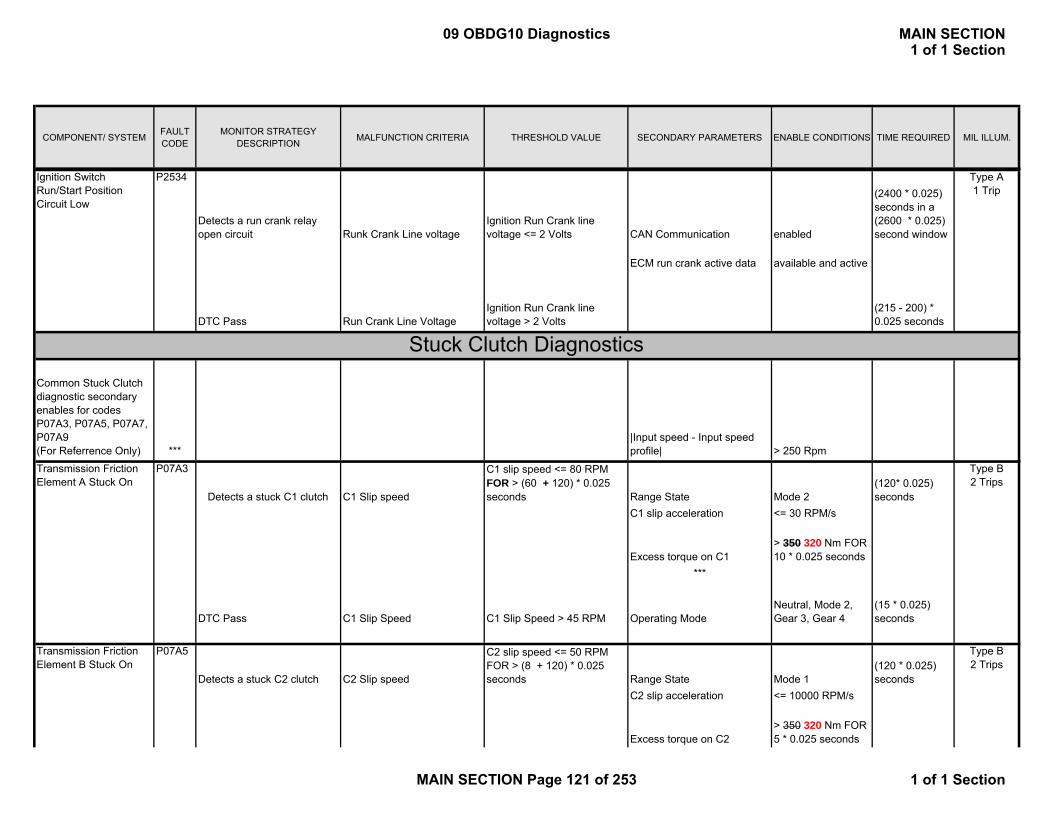
COMPONENT/ SYSTEM FAULT CODE
MONITOR STRATEGY DESCRIPTION MALFUNCTION CRITERIA THRESHOLD VALUE SECONDARY PARAMETERS ENABLE CONDITIONS TIME REQUIRED MIL ILLUM.
Detects a run crank relay open circuit Runk Crank Line voltage
Ignition Run Crank line voltage <= 2 Volts CAN Communication enabled
(2400 * 0.025) seconds in a (2600 * 0.025) second window
ECM run crank active data available and active
DTC Pass Run Crank Line VoltageIgnition Run Crank line voltage > 2 Volts
(215 - 200) * 0.025 seconds
Common Stuck Clutch diagnostic secondary enables for codes P07A3, P07A5, P07A7, P07A9 (For Referrence Only) ***
|Input speed - Input speed profile| > 250 Rpm
Detects a stuck C1 clutch C1 Slip speed
C1 slip speed <= 80 RPM FOR > (60 + 120) * 0.025 seconds Range State Mode 2
(120* 0.025) seconds
C1 slip acceleration <= 30 RPM/s
Excess torque on C1 > 350 320 Nm FOR 10 * 0.025 seconds
***
DTC Pass C1 Slip Speed C1 Slip Speed > 45 RPM Operating ModeNeutral, Mode 2, Gear 3, Gear 4
(15 * 0.025) seconds
Detects a stuck C2 clutch C2 Slip speed
C2 slip speed <= 50 RPM FOR > (8 + 120) * 0.025 seconds Range State Mode 1
(120 * 0.025) seconds
C2 slip acceleration <= 10000 RPM/s
Excess torque on C2> 350 320 Nm FOR 5 * 0.025 seconds
P2534
P07A3
P07A5
Ignition Switch Run/Start Position Circuit Low
Transmission Friction Element A Stuck On
Transmission Friction Element B Stuck On
Stuck Clutch Diagnostics
Type A 1 Trip
Type B 2 Trips
Type B 2 Trips
09 OBDG10 Diagnostics MAIN SECTION1 of 1 Section
MAIN SECTION Page 121 of 253 1 of 1 Section

COMPONENT/ SYSTEM FAULT CODE
MONITOR STRATEGY DESCRIPTION MALFUNCTION CRITERIA THRESHOLD VALUE SECONDARY PARAMETERS ENABLE CONDITIONS TIME REQUIRED MIL ILLUM.
***
DTC Pass C2 Slip Speed C2 Slip Speed > 70 RPM Operating ModeNeutral, Mode 1, Gear 1
(10 * 0.025) seconds
Detects a stuck C3 clutch C3 Slip speed
C3 slip speed <= 80 RPM FOR > (60 + 120) * 0.025 seconds Range State Mode 2
(120 * 0.025) seconds
C3 slip acceleration <= 30 RPM/s
Excess torque on C3> 200140 Nm FOR 10 * 0.025 seconds
***
DTC Pass C3 Slip Speed C3 Slip Speed > 45 RPM Operating Mode
Neutral, Mode 1, Mode 2, Gear 1, Gear 2, Gear 3
(15 * 0.025) seconds
Detects a stuck C4 clutch C4 Slip speed
Fail Case 1: C4 slip speed <= 100 PRM FOR > (4 + 120) * 0.025 seconds Range State Mode 1
(120* 0.025) seconds
C4 slip acceleration <= 10000 RPM/s
Excess torque on C4> 300 700 Nm FOR 5 * 0.025 seconds
***
Fail Case 2: C4 slip speed <= 80 RPM FOR > (60 + 120) * 0.025 seconds Range State Mode 2
(120 * 0.025) seconds
C4 slip acceleration <= 50 RPM/s
Excess torque on C4> 200 180 Nm FOR 10 * 0.025 seconds
***
P07A7
P07A9 Type B 2 Trips
Transmission Friction Element C Stuck On
Transmission Friction Element D Stuck On
Type B 2 Trips
09 OBDG10 Diagnostics MAIN SECTION1 of 1 Section
MAIN SECTION Page 122 of 253 1 of 1 Section

COMPONENT/ SYSTEM FAULT CODE
MONITOR STRATEGY DESCRIPTION MALFUNCTION CRITERIA THRESHOLD VALUE SECONDARY PARAMETERS ENABLE CONDITIONS TIME REQUIRED MIL ILLUM.
DTC Pass C4 Slip Speed C4 Slip Speed > 150 RPM Operating Mode
Neutral, Mode 1, Mode 2, Gear 2, Gear 4
(10 * 0.025) seconds
This DTC sets when the TAOP controller is not communicating with the HCP
Incomplete or no fault message communication with TAOP controller.
A complete fault status message must be received every 1.5 seconds RunCrankActive
= 1 for more than 0.2 seconds 1.5 seconds
This diagnostic monitors the aux pump performance based on aux pump desired and actual speed values Aux pump speed
|Aux pump speed - Commanded Aux pump Speed| > 500 RPM RunCrankActive
= 1 for more than KeTAPD_t_DiagDlyIgnOn seconds
Fail Condition met for (160 * 0.025) seconds in a (165 * 0.025) second window
Desired Speed
>= KeTAPD_n_PmpPerf_MinSpd
DTC Pass Aux pump speed
|Aux pump speed - Commanded Aux pump Speed| <= 500 RPM
Pass met for (165-160) * 0.025 seconds
The DTC Monitors the Calculated Input Speed and Compares this with the Sensed Engine Speed
SPI Sensed Engine Speed and Input Speed
Sensed SPI Engine Speed Above 1500 RPM a difference ≥ 250 RPM else ≥ 1500 RPM
Ignition Voltage ≥ 6.0 V for 2 consecutive samples
160 failure counts out of 320 [email protected] ms loop
P0C2B
Transmission Auxilary Oil Pump Diagnostics
System Speed Rationality
Auxiliary Transmission Fluid Pump Performance
Type B 2 Trips
P0C2F Type A 1 Trip
P2797
Internal Control Module Drive Motor/Generator - Engine Speed Sensor Performance
Transmission Auxiliary Oil Pump (TAOP) Feedback Signal out of Bound
Type B 2 Trips
09 OBDG10 Diagnostics MAIN SECTION1 of 1 Section
MAIN SECTION Page 123 of 253 1 of 1 Section

COMPONENT/ SYSTEM FAULT CODE
MONITOR STRATEGY DESCRIPTION MALFUNCTION CRITERIA THRESHOLD VALUE SECONDARY PARAMETERS ENABLE CONDITIONS TIME REQUIRED MIL ILLUM.
CAN Sensed Engine Speed and Input Speed
Sensed CAN Engine Speed Above 1500 RPM a difference ≥ 250 RPM else ≥ 1500 RPM
Pass Conditions: Sensed SPI Engine Speed Above 500 RPM a difference ≤ 150 RPM else ≤ 1500 RPM
Pass Conditions: Sensed CAN Engine Speed Above 500 RPM a difference ≤ 150 RPM else ≤ 1500 RPM for 500ms
The DTC detects if the Transmission Output Speed Sensor Direction is Incorrect by Comparing with Calculated Direction from Motor Speed Sign
Transmission Output Speed Direction Raw
≠ Motor Direction Transmission Output Speed Not FAULT ACTIVE 1.15 0.3 seconds (46 12 counts at 25ms)
Hybrid Motor Speed based Estimated Output Speed is Valid
Calculated based on M1 or M2 Speed Equation
Transmission Output Speed and Motor Output Speed Difference
≤ 50 RPM Pass Conditions: Same as FAIL for 5 seconds (200 counts at 25ms)
Motor Estimated Transmission Output Speed
≥ 50 RPM
Transmission Output Speed SensorType A 1 Trip
P077BOutput Speed Sensor Circuit Direction Error
09 OBDG10 Diagnostics MAIN SECTION1 of 1 Section
MAIN SECTION Page 124 of 253 1 of 1 Section

COMPONENT/ SYSTEM FAULT CODE
MONITOR STRATEGY DESCRIPTION MALFUNCTION CRITERIA THRESHOLD VALUE SECONDARY PARAMETERS ENABLE CONDITIONS TIME REQUIRED MIL ILLUM.
The DTC Monitors if the IMS R1 Circuit is Shorted to a Low Voltage
Converted Directional IMS Transitional 17 Ignition Voltage ≥ 6.0 V for 2 consecutive samples
2.7 seconds
AND Directional IMS R1 R1 Position Has Not Been Observed High
Converted Directional IMS Transitional 2 Pass Conditions: Has Been Observed High for 3.125 seconds
AND Directional IMS R1 R1 Position NOT High for 5 seconds
The DTC Monitors if the IMS R1 Circuit is Shorted to a High Voltage
Converted Directional IMS Transitional 30 Ignition Voltage ≥ 6.0 V for 2 consecutive samples
2.7 seconds
AND Directional IMS R1 R1 Position Has Not Been Observed Low
Pass Conditions: Has Been Observed Low for 3.125 seconds
The DTC Monitors if the IMS R2 Circuit is Shorted to a Low Voltage
Converted Directional IMS DRIVE Ignition Voltage ≥ 6.0 V for 2 consecutive samples
2.7 seconds
AND Directional IMS R2 R2 Position Has Not Been Observed High
Converted Directional IMS PARK Pass Conditions: Has Been Observed High for 3.125 seconds
AND Directional IMS R2 R2 Position Low for 5 seconds
The DTC Monitors if the IMS R2 Circuit is Shorted to a High Voltage
Converted Directional IMS Transitional 14 OR Transitional 29
Ignition Voltage ≥ 6.0 V for 2 consecutive samples
2.7 seconds
Internal Mode Switch 2
P181E
P181F
Type B 2 Trips
Type B 2 Trips
P181D
Internal Mode Switch 2 R2 Circuit Low Voltage
Internal Mode Switch 2 R2 Circuit High Voltage
Type B 2 Trips
Internal Mode Switch 2 R1 Circuit High Voltage
Internal Mode Switch 2 R1 Circuit Low Voltage
P181C
Type B 2 Trips
09 OBDG10 Diagnostics MAIN SECTION1 of 1 Section
MAIN SECTION Page 125 of 253 1 of 1 Section

COMPONENT/ SYSTEM FAULT CODE
MONITOR STRATEGY DESCRIPTION MALFUNCTION CRITERIA THRESHOLD VALUE SECONDARY PARAMETERS ENABLE CONDITIONS TIME REQUIRED MIL ILLUM.
AND Directional IMS R2 R2 Position Has Not Been Observed Low
Pass Conditions: Has Been Observed Low for 3.125 seconds
The DTC Monitors if the IMS D1 Circuit is Shorted to a Low Voltage
Converted Directional IMS Transitional 8 OR Transitional 20
Ignition Voltage ≥ 6.0 V for 2 consecutive samples
2.7 seconds
AND Directional IMS D1 D1 Position Has Not Been Observed High
Pass Conditions: Has Been Observed High for 3.125 seconds
The DTC Monitors if the IMS D1 Circuit is Shorted to a High Voltage
Converted Directional IMS Transitional 27 Ignition Voltage ≥ 6.0 V for 2 consecutive samples
2.7 seconds Type B 2 Trips
AND Directional IMS D1 D1 Position Has Not Been Observed Low
Pass Conditions: Has Been Observed Low for 3.125 seconds
The DTC Monitors if the IMS D2 Circuit is Shorted to a Low Voltage
Converted Directional IMS Transitional 24 Ignition Voltage ≥ 6.0 V for 2 consecutive samples
2.7 seconds
AND Directional IMS D1 D2 Position Has Not Been Observed High
Pass Conditions: Has Been Observed High for 3.125 seconds
The DTC Monitors if the IMS D2 Circuit is Shorted to a High Voltage
Converted Directional IMS Transitional 11 AND Transitional 23
Ignition Voltage ≥ 6.0 V for 2 consecutive samples
2.7 seconds
P183A Type B 2 Trips
Type B 2 Trips
Type B 2 Trips
P183D
Internal Mode Switch 2 D1 Circuit Low Voltage
Internal Mode Switch 2 D1 Circuit High Voltage
Internal Mode Switch 2 D2 Circuit Low Voltage
Internal Mode Switch 2 D2 Circuit High Voltage
P183B
P183C
09 OBDG10 Diagnostics MAIN SECTION1 of 1 Section
MAIN SECTION Page 126 of 253 1 of 1 Section

COMPONENT/ SYSTEM FAULT CODE
MONITOR STRATEGY DESCRIPTION MALFUNCTION CRITERIA THRESHOLD VALUE SECONDARY PARAMETERS ENABLE CONDITIONS TIME REQUIRED MIL ILLUM.
AND Directional IMS D2 D2 Position Has Not Been Observed Low
Pass Conditions: Has Been Observed Low for 3.125 seconds
The DTC Monitors if the IMS is in an Invalid Range
Converted Directional IMS Illegal (All Circuits Open) Ignition Voltage ≥ 6.0 V for 2 consecutive samples
2.7 seconds
Pass Conditions: Same as Fail for 3.125 seconds
The DTC Monitors if the IMS Direction and Range Correlation is Invalid
Converted Directional IMS Correlation Fault Neutral (With No IMS Faults the Direction IMS and Range IMS Indicate Different Detent Postions)
Ignition Voltage ≥ 6.0 V for 2 consecutive samples
1.25 seconds
Pass Conditions: Same as Fail for 1.7 seconds
The DTC Monitors if the IMS S Circuit is Shorted to a Low Voltage
Converted Directional IMS Transitional 9 Ignition Voltage ≥ 6.0 V for 2 consecutive samples
2.7 seconds
AND Directional IMS S S Position Has Not Been Observed High
Pass Conditions: Has Been Observed High for 3.125 seconds
The DTC Monitors if the IMS S Circuit is Shorted to a High Voltage
Converted Directional IMS Transitional 26 AND DRIVE Ignition Voltage ≥ 6.0 V for 2 consecutive samples
2.7 seconds
P183E
P183F
Type B 2 Trips
Type B 2 Trips
Internal Mode Switch 1-2 Correlation
Internal Mode Switch 2 S Circuit High Voltage
Internal Mode Switch 2-Invalid Range
P184B
Internal Mode Switch 2 S Circuit Low Voltage
P184A
Type B 2 Trips
Type A 1 Trip
09 OBDG10 Diagnostics MAIN SECTION1 of 1 Section
MAIN SECTION Page 127 of 253 1 of 1 Section
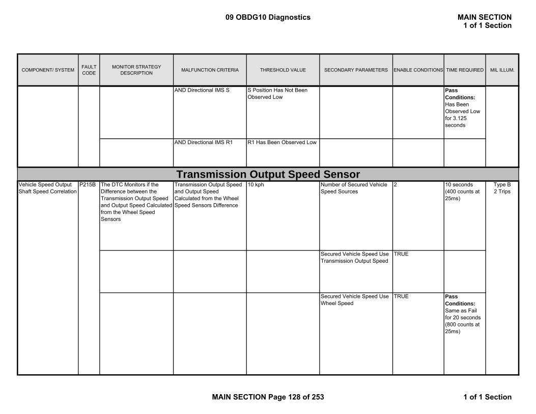
COMPONENT/ SYSTEM FAULT CODE
MONITOR STRATEGY DESCRIPTION MALFUNCTION CRITERIA THRESHOLD VALUE SECONDARY PARAMETERS ENABLE CONDITIONS TIME REQUIRED MIL ILLUM.
AND Directional IMS S S Position Has Not Been Observed Low
Pass Conditions: Has Been Observed Low for 3.125 seconds
AND Directional IMS R1 R1 Has Been Observed Low
The DTC Monitors if the Difference between the Transmission Output Speed and Output Speed Calculated from the Wheel Speed Sensors
Transmission Output Speed and Output Speed Calculated from the Wheel Speed Sensors Difference
10 kph Number of Secured Vehicle Speed Sources
2 10 seconds (400 counts at 25ms)
Secured Vehicle Speed Use Transmission Output Speed
TRUE
Secured Vehicle Speed Use Wheel Speed
TRUE Pass Conditions: Same as Fail for 20 seconds (800 counts at 25ms)
Transmission Output Speed SensorVehicle Speed Output Shaft Speed Correlation
P215B Type B 2 Trips
09 OBDG10 Diagnostics MAIN SECTION1 of 1 Section
MAIN SECTION Page 128 of 253 1 of 1 Section

COMPONENT/ SYSTEM FAULT CODE
MONITOR STRATEGY DESCRIPTION MALFUNCTION CRITERIA THRESHOLD VALUE SECONDARY PARAMETERS ENABLE CONDITIONS TIME REQUIRED MIL ILLUM.
Control Module Read Only Memory (Rom)
P0601 This DTC will be stored if any software or calibration check sum is incorrect
Calculated Checksum does not match stored checksum
Ignition Status Run or Crank
1 failure if it occursduring the first ROMtest of the ignition cycle, otherwise 5 failures
Frequency:Runs continuously in the background
Type A 1 Trip
Control Module Not Programmed
P0602 Indicates that the HCP needs to be programmed
Fails if No Start Calibration is set to true which is only available on a new un-programmed HCP
Ignition Status Run or Crank
Runs once at power up
Type A 1 Trip
Control Module Long Term Memory Reset
P0603 Non-volatile memory checksum error at controller power-up
Checksum at power-up does not match checksum at power-down
Ignition Status Run or Crank
1 failure
Frequency:Once at powerup
Type A 1 Trip
Control Module Random Access Memory (RAM) Failure
P0604 Indicates that HCP is unable to correctly write and read data to and from RAM
Data read does not match data written
Ignition Status Run or Crank
Should finish within 30 seconds at all operating conditions
Type A 1 Trip
Controller Diagnostics
09 OBDG10 Diagnostics MAIN SECTION1 of 1 Section
MAIN SECTION Page 129 of 253 1 of 1 Section

COMPONENT/ SYSTEM FAULT CODE
MONITOR STRATEGY DESCRIPTION MALFUNCTION CRITERIA THRESHOLD VALUE SECONDARY PARAMETERS ENABLE CONDITIONS TIME REQUIRED MIL ILLUM.
Ignition Status Accessory, Run, Crank
≥ 5 volts 1 failure
Frequency:Once at power-up
> 9.5 Volts OR < 18 Volts
Run/Crank Voltage OR Powertrain Relay Voltage
Type A 1 Trip
Type A 1 Trip
Control Module Long Term Memory Performance
P062F Indicates that the NVM Error flag has not been cleared
Last EEPROM write did not complete
Indicates that the HCP has detected an internal processor integrity fault
PCM Processor Performance/Integrity Check
1. Main processor Arithmetic Logic Unit (ALU) fault2. Main configuration register fault3. Software timed loop execution4. Communication (SPI bus) between main and secondary processors
P0606 1. Main (ALU)Failure: 2 times in a row @ 50ms2.Main (config)Failure: 2 times in a row @ 50ms3. N/A4. SPIFailure: MCP 10 fail counts out of 30 sample counts Executes: 6.25ms loop PLD 3 fail counts out of 10 sample counts Executes: 50ms loop
1. ALU not reporting as expected2. Configuration register not reporting as expected3. Software tasks loops > schedule tasks loop4. Loss of SPI communication between main and secondary processors
Ignition voltage
09 OBDG10 Diagnostics MAIN SECTION1 of 1 Section
MAIN SECTION Page 130 of 253 1 of 1 Section
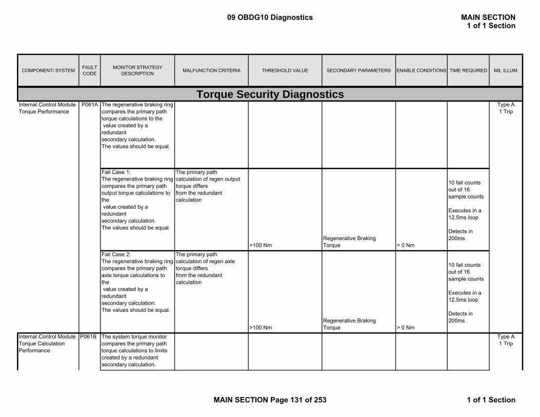
COMPONENT/ SYSTEM FAULT CODE
MONITOR STRATEGY DESCRIPTION MALFUNCTION CRITERIA THRESHOLD VALUE SECONDARY PARAMETERS ENABLE CONDITIONS TIME REQUIRED MIL ILLUM.
The regenerative braking ring compares the primary path torque calculations to the value created by a redundant secondary calculation. The values should be equal.
Fail Case 1:The regenerative braking ring compares the primary path output torque calculations to the value created by a redundant secondary calculation. The values should be equal.
The primary path calculation of regen output torque differs from the redundant calculation
>100 NmRegenerative Braking Torque > 0 Nm
10 fail counts out of 16 sample counts
Executes in a12.5ms loop
Detects in 200ms
Fail Case 2:The regenerative braking ring compares the primary path axle torque calculations to the value created by a redundant secondary calculation. The values should be equal.
The primary path calculation of regen axle torque differs from the redundant calculation
>100 NmRegenerative Braking Torque > 0 Nm
10 fail counts out of 16 sample counts
Executes in a12.5ms loop
Detects in 200ms
The system torque monitor compares the primary path torque calculations to limits created by a redundant secondary calculation.
Torque Security Diagnostics
Internal Control Module Torque Calculation Performance
P061B Type A 1 Trip
Internal Control Module Torque Performance
P061A Type A 1 Trip
09 OBDG10 Diagnostics MAIN SECTION1 of 1 Section
MAIN SECTION Page 131 of 253 1 of 1 Section

COMPONENT/ SYSTEM FAULT CODE
MONITOR STRATEGY DESCRIPTION MALFUNCTION CRITERIA THRESHOLD VALUE SECONDARY PARAMETERS ENABLE CONDITIONS TIME REQUIRED MIL ILLUM.
Fail Case 1:Exceeds upper torque limit
When the redundant calculation of the system torque exceeds the upper limit created by the primary torque calculation (0.2g = 678Nm offset) for greater than 200ms
678Nm (equivalent to .2g)
Runs continuously when a torque source is present
14 fail counts out of 16 sample counts
Executes in a12.5ms loop
Detects in 200ms
508Nm
14 fail counts out of 16 sample counts
(equivalent to .15g)Executes in a12.5ms loop
Detects in 200ms14 fail counts out of 16 sample counts
Executes in a12.5ms loop
Detects in 200ms14 fail counts out of 16 sample counts
Executes in a12.5ms loop
Detects in 200ms
Fail Case 3: Transmission output torque rationality check violated
Axle torque request is converted to transmission output torque. When this converted output torque violates the rationality check comparison by 1 Nm for greater than 200ms a failure is flagged.
Fail Case 2: Exceeds lower torque limit
Fail Case 4: Brake torque request rationality check violated
Runs continuously when a torque source is present
Runs continuously when a torque source is present
Brake torque request is converted to transmission output torque. When this converted output torque violates the rationality check comparison by 1 Nm for greater than 200ms a failure is flagged.
1Nm
When the redundant calculation of the system torque exceeds the lower limit created by the primary torque calculation (0.15g = 508Nm offset) for greater than 200ms
Runs continuously when a torque source is present
1Nm
09 OBDG10 Diagnostics MAIN SECTION1 of 1 Section
MAIN SECTION Page 132 of 253 1 of 1 Section

COMPONENT/ SYSTEM FAULT CODE
MONITOR STRATEGY DESCRIPTION MALFUNCTION CRITERIA THRESHOLD VALUE SECONDARY PARAMETERS ENABLE CONDITIONS TIME REQUIRED MIL ILLUM.
-340Nm
14 fail counts out of 16 sample counts
(equivalent to -0.1g)Executes in a12.5ms loop
Detects in 200ms
340Nm
14 fail counts out of 16 sample counts
(equivalent to 0.1g)Executes in a12.5ms loop
Detects in 200ms14 fail counts out of 16 sample counts
Executes in a12.5ms loop
Detects in 200ms4 fail counts out of 6 sample countsExecutes in a 12.5 ms Loop
Detects in 200ms
The pattern does not match (F, 5, B, D, A, 6, 3, 0)
Run/Crank Voltage OR Powertrain Relay Voltage
> 9.5 Volts OR < 18 Volts
The nibble pattern is incorrect
Torque Management System – Forced Engine Shutdown
P06AF
Fail Case 7: Input Torque correction rationality check violated
When the difference between the primary and the redundantly calculated input torque correction exceeds 1Nm for greater than 200ms a failure is flagged
1Nm
When the PRNDL equals reverse and driver requested torque is negative while the commanded output torque is positive and greater than a 0.1g (340Nm) threshold for greater than 200ms.
Type A 1 Trip
The main processor monitor ring compares the ECM 2nd pattern (nibble pattern) to known good pattern to determine ECM state of health.
Fail Case 6: Output torque positive when driver request is negative
Runs continuously when a torque source is present
Enabled at low speed (7mph or less) or a TOSS sensor fault is active or vehicle speed sensor fault is active
Fail Case 5: Output torque negative when driver request is positive
When the PRNDL equals drive and the driver requested torque is positive while the commanded output torque is negative and below a -0.1g (-340Nm) threshold for greater than 200ms.
Enabled at low speed (7mph or less) or a TOSS sensor fault is active or vehicle speed sensor fault is active
09 OBDG10 Diagnostics MAIN SECTION1 of 1 Section
MAIN SECTION Page 133 of 253 1 of 1 Section
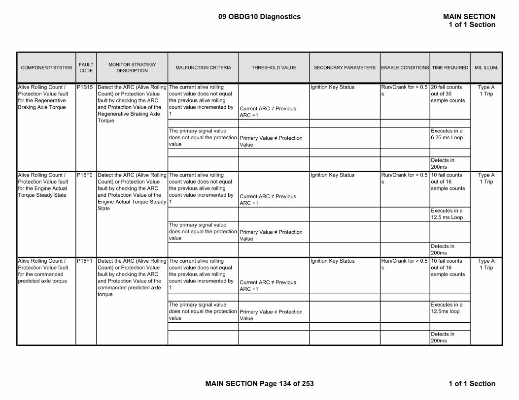
COMPONENT/ SYSTEM FAULT CODE
MONITOR STRATEGY DESCRIPTION MALFUNCTION CRITERIA THRESHOLD VALUE SECONDARY PARAMETERS ENABLE CONDITIONS TIME REQUIRED MIL ILLUM.
The current alive rolling count value does not equal the previous alive rolling count value incremented by 1
Current ARC ≠ Previous ARC +1
Ignition Key Status Run/Crank for > 0.5 s
20 fail counts out of 30 sample counts
The primary signal value does not equal the protection value
Primary Value ≠ Protection Value
Executes in a 6.25 ms Loop
Detects in 200ms
The current alive rolling count value does not equal the previous alive rolling count value incremented by 1
Current ARC ≠ Previous ARC +1
Ignition Key Status Run/Crank for > 0.5 s
10 fail counts out of 16 sample counts
Executes in a 12.5 ms Loop
The primary signal value does not equal the protection value
Primary Value ≠ Protection Value
Detects in 200ms
The current alive rolling count value does not equal the previous alive rolling count value incremented by 1
Current ARC ≠ Previous ARC +1
Ignition Key Status Run/Crank for > 0.5 s
10 fail counts out of 16 sample counts
The primary signal value does not equal the protection value
Primary Value ≠ Protection Value
Executes in a 12.5ms loop
Detects in 200ms
Type A 1 Trip
Alive Rolling Count / Protection Value fault for the commanded predicted axle torque
P15F1 Type A 1 Trip
Detect the ARC (Alive Rolling Count) or Protection Value fault by checking the ARC and Protection Value of the commanded predicted axle torque
Alive Rolling Count / Protection Value fault for the Engine Actual Torque Steady State
P15F0 Detect the ARC (Alive Rolling Count) or Protection Value fault by checking the ARC and Protection Value of the Engine Actual Torque Steady State
Alive Rolling Count / Protection Value fault for the Regenerative Braking Axle Torque
P1B15 Detect the ARC (Alive Rolling Count) or Protection Value fault by checking the ARC and Protection Value of the Regenerative Braking Axle Torque
Type A 1 Trip
09 OBDG10 Diagnostics MAIN SECTION1 of 1 Section
MAIN SECTION Page 134 of 253 1 of 1 Section

COMPONENT/ SYSTEM FAULT CODE
MONITOR STRATEGY DESCRIPTION MALFUNCTION CRITERIA THRESHOLD VALUE SECONDARY PARAMETERS ENABLE CONDITIONS TIME REQUIRED MIL ILLUM.
Detect transmission direction errors by reading the states of the Direction IMS switches as well as determining a transmission direction and comparing it to the transmission direction from the primary controls path.
6 fail counts out of 8 sample counts
Executes in a12.5ms loop
Detects in 200ms6 fail counts out of 8 sample counts
Executes in a12.5ms loop
Detects in 200ms6 fail counts out of 8 sample counts
Executes in a12.5ms loop
Detects in 200ms6 fail counts out of 8 sample counts
> 9.5 Volts OR < 18 Volts
Fail Case 4: Multiple transmission directions with one IMS failure
Read the Direction IMS switches and determine that one switch has failed and
l l t t i i
Run/Crank Voltage OR Powertrain Relay Voltage
> 9.5 Volts OR < 18 Volts
Read the Direction IMS switches and determine that they represent more than one valid transmission direction (P,R,N,D).
Run/Crank Voltage OR Powertrain Relay Voltage
Fail Case 3: No direction match with one IMS failure
Read the Direction IMS switches and determine that one switch has failed and calculate a transmission direction, but it does not match the transmission direction determined by the primary controls path.
Run/Crank Voltage OR Powertrain Relay Voltage
Internal Control Module Transmission Direction Range Switch
P16F2 Type A 1 Trip
Fail Case 1: No direction match with no IMS failures
Read the Direction IMS switches and determine that they represent a valid transmission direction (P,R,N,D) but it does not match the transmission direction determined by the primary controls path.
Run/Crank Voltage OR Powertrain Relay Voltage
> 9.5 Volts OR < 18 Volts
Fail Case 2: Multiple transmission directions with no IMS failures
> 9.5 Volts OR < 18 Volts
09 OBDG10 Diagnostics MAIN SECTION1 of 1 Section
MAIN SECTION Page 135 of 253 1 of 1 Section
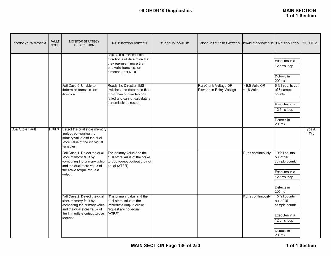
COMPONENT/ SYSTEM FAULT CODE
MONITOR STRATEGY DESCRIPTION MALFUNCTION CRITERIA THRESHOLD VALUE SECONDARY PARAMETERS ENABLE CONDITIONS TIME REQUIRED MIL ILLUM.
Executes in a12.5ms loop
Detects in 200ms6 fail counts out of 8 sample counts
Executes in a12.5ms loop
Detects in 200ms
10 fail counts out of 16 sample counts
Executes in a12.5ms loop
Detects in 200ms10 fail counts out of 16 sample counts
Executes in a12.5ms loop
Detects in 200ms
Type A 1 Trip
Fail Case 1: Detect the dual store memory fault by comparing the primary value and the dual store value of the brake torque request output
The primary value and the dual store value of the brake torque request output are not equal (ATRR)
Runs continuously
Fail Case 2: Detect the dual store memory fault by comparing the primary value and the dual store value of the immediate output torque request
The primary value and the dual store value of the immediate output torque request are not equal (ATRR)
Dual Store Fault P16F3 Detect the dual store memory fault by comparing the primary value and the dual store value of the individual variables
Runs continuously
Fail Case 5: Unable to determine transmission direction
Reads the Direction IMS switches and determine that more than one switch has failed and cannot calculate a transmission direction.
Run/Crank Voltage OR Powertrain Relay Voltage
> 9.5 Volts OR < 18 Volts
calculate a transmission direction and determine that they represent more than one valid transmission direction (P,R,N,D).
09 OBDG10 Diagnostics MAIN SECTION1 of 1 Section
MAIN SECTION Page 136 of 253 1 of 1 Section

COMPONENT/ SYSTEM FAULT CODE
MONITOR STRATEGY DESCRIPTION MALFUNCTION CRITERIA THRESHOLD VALUE SECONDARY PARAMETERS ENABLE CONDITIONS TIME REQUIRED MIL ILLUM.
10 fail counts out of 16 sample counts
Executes in a12.5ms loop
Detects in 200ms10 fail counts out of 16 sample counts
Executes in a12.5ms loop
Detects in 200ms5 fail counts out of 16 sample counts
Executes in a25ms loop
Detects in 200ms5 fail counts out of 8 sample counts
Executes in a25ms loop
Detects in 200ms
Runs continuouslyFail Case 6: Detect the dual store memory fault by comparing the primary value and the dual store value of the selected range equation
The primary value and the dual store value of the selected range equation are not equal (HSER)
Runs continuously
Fail Case 4: Detect the dual store memory fault by comparing the primary value and the dual store value of the Engine Actual Torque Steady State
The primary value and the dual store value of the Engine Actual Torque Steady State are not equal (ETQR)
Fail Case 5: Detect the dual store memory fault by comparing the primary value and the dual store value of the transfer case range (4wd) variables
The primary value and the dual store value of the transfer case range (4wd) are not equal (FWDR)
Fail Case 3: Detect the dual store memory fault by comparing the primary value and the dual store value of the commanded predicted axle torque
The primary value and the dual store value of the commanded predicted axle torque are not equal (AXLR)
Runs continuously
Runs continuously
09 OBDG10 Diagnostics MAIN SECTION1 of 1 Section
MAIN SECTION Page 137 of 253 1 of 1 Section
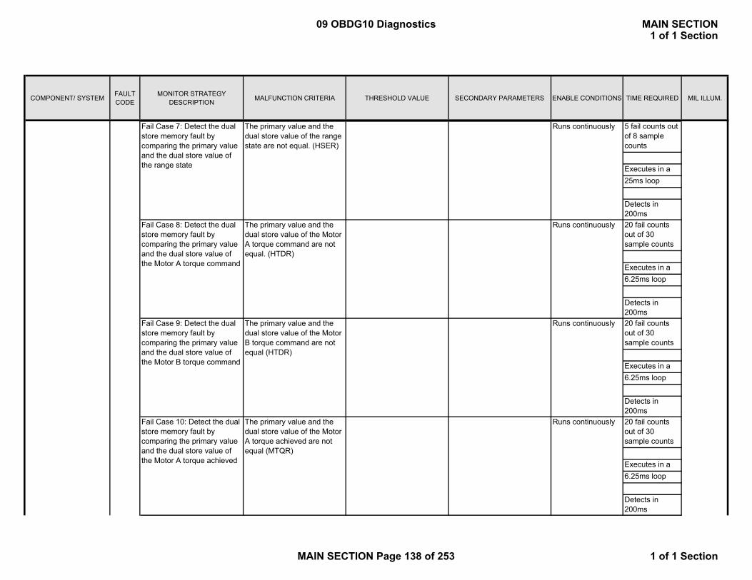
COMPONENT/ SYSTEM FAULT CODE
MONITOR STRATEGY DESCRIPTION MALFUNCTION CRITERIA THRESHOLD VALUE SECONDARY PARAMETERS ENABLE CONDITIONS TIME REQUIRED MIL ILLUM.
5 fail counts out of 8 sample counts
Executes in a25ms loop
Detects in 200ms20 fail counts out of 30 sample counts
Executes in a6.25ms loop
Detects in 200ms20 fail counts out of 30 sample counts
Executes in a6.25ms loop
Detects in 200ms20 fail counts out of 30 sample counts
Executes in a6.25ms loop
Detects in 200ms
Runs continuouslyFail Case 10: Detect the dual store memory fault by comparing the primary value and the dual store value of the Motor A torque achieved
The primary value and the dual store value of the Motor A torque achieved are not equal (MTQR)
Runs continuously
Fail Case 9: Detect the dual store memory fault by comparing the primary value and the dual store value of the Motor B torque command
The primary value and the dual store value of the Motor B torque command are not equal (HTDR)
Runs continuously
Fail Case 8: Detect the dual store memory fault by comparing the primary value and the dual store value of the Motor A torque command
The primary value and the dual store value of the Motor A torque command are not equal. (HTDR)
Fail Case 7: Detect the dual store memory fault by comparing the primary value and the dual store value of the range state
The primary value and the dual store value of the range state are not equal. (HSER)
Runs continuously
09 OBDG10 Diagnostics MAIN SECTION1 of 1 Section
MAIN SECTION Page 138 of 253 1 of 1 Section
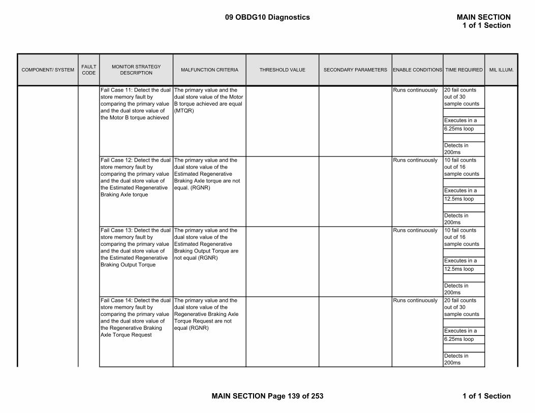
COMPONENT/ SYSTEM FAULT CODE
MONITOR STRATEGY DESCRIPTION MALFUNCTION CRITERIA THRESHOLD VALUE SECONDARY PARAMETERS ENABLE CONDITIONS TIME REQUIRED MIL ILLUM.
20 fail counts out of 30 sample counts
Executes in a6.25ms loop
Detects in 200ms10 fail counts out of 16 sample counts
Executes in a12.5ms loop
Detects in 200ms10 fail counts out of 16 sample counts
Executes in a12.5ms loop
Detects in 200ms20 fail counts out of 30 sample counts
Executes in a6.25ms loop
Detects in 200ms
Runs continuouslyFail Case 14: Detect the dual store memory fault by comparing the primary value and the dual store value of the Regenerative Braking Axle Torque Request
The primary value and the dual store value of the Regenerative Braking Axle Torque Request are not equal (RGNR)
Runs continuously
Fail Case 13: Detect the dual store memory fault by comparing the primary value and the dual store value of the Estimated Regenerative Braking Output Torque
The primary value and the dual store value of the Estimated Regenerative Braking Output Torque are not equal (RGNR)
Runs continuously
Fail Case 12: Detect the dual store memory fault by comparing the primary value and the dual store value of the Estimated Regenerative Braking Axle torque
The primary value and the dual store value of the Estimated Regenerative Braking Axle torque are not equal. (RGNR)
Fail Case 11: Detect the dual store memory fault by comparing the primary value and the dual store value of the Motor B torque achieved
The primary value and the dual store value of the Motor B torque achieved are equal (MTQR)
Runs continuously
09 OBDG10 Diagnostics MAIN SECTION1 of 1 Section
MAIN SECTION Page 139 of 253 1 of 1 Section

COMPONENT/ SYSTEM FAULT CODE
MONITOR STRATEGY DESCRIPTION MALFUNCTION CRITERIA THRESHOLD VALUE SECONDARY PARAMETERS ENABLE CONDITIONS TIME REQUIRED MIL ILLUM.
20 fail counts out of 30 sample counts
Executes in a6.25ms loop
Detects in 200ms10 fail counts out of 16 sample counts
Executes in a12.5ms loop
Detects in 200ms5 fail counts out of 8 sample counts
Executes in a25ms loop
Detects in 200ms5 fail counts out of 8 sample counts
Executes in a25ms loop
Detects in 200ms
Runs continuouslyFail Case 18: Detect the dual store memory fault by comparing the primary value and the dual store value of the Trans Direction State Fault Active
The primary value and the dual store value of the Trans Direction State Fault Active are not equal (TRGR)
Runs continuously
Fail Case 17: Detect the dual store memory fault by comparing the primary value and the dual store value of the Direction IMS Failure Active status
The primary value and the dual store value of the Direction IMS Failure Active status are not equal (TRGR)
Runs continuously
Fail Case 16: Detect the dual store memory fault by comparing the primary value and the dual store value of the Hybrid Commanded Engine Torque
The primary value and the dual store value of the Hybrid Commanded Engine Torque are not equal (TRAR)
Fail Case 15: Detect the dual store memory fault by comparing the primary value and the dual store value of the Trans input speed
The primary value and the dual store value of the Trans input speed are not equal (TISR)
Runs continuously
09 OBDG10 Diagnostics MAIN SECTION1 of 1 Section
MAIN SECTION Page 140 of 253 1 of 1 Section

COMPONENT/ SYSTEM FAULT CODE
MONITOR STRATEGY DESCRIPTION MALFUNCTION CRITERIA THRESHOLD VALUE SECONDARY PARAMETERS ENABLE CONDITIONS TIME REQUIRED MIL ILLUM.
5 fail counts out of 8 sample counts
Executes in a25ms loop
Detects in 200ms5 fail counts out of 8 sample counts
Executes in a25ms loop
Detects in 200ms5 fail counts out of 8 sample counts
Executes in a25ms loop
Detects in 200ms5 fail counts out of 8 sample counts
Executes in a25ms loop
Detects in 200ms
Runs continuouslyFail Case 22: Detect the dual store memory fault by comparing the primary value and the dual store value of the rate limited secure vehicle speed
The primary value and the dual store value of the rate limited secure vehicle speed are not equal (VSPR)
Runs continuously
Fail Case 21: Detect the dual store memory fault by comparing the primary value and the dual store value of the conversion factor for TOS
The primary value and the dual store value of the conversion factor for TOS are not equal (VSPR)
Runs continuously
Fail Case 20: Detect the dual store memory fault by comparing the primary value and the dual store value of the Validated Trans Range State
The primary value and the dual store value of the Validated Trans Range State are not equal (TRGR)
Fail Case 19: Detect the dual store memory fault by comparing the primary value and the dual store value of the Transmission Direction State.
The primary value and the dual store value of the Transmission Direction State are not equal (TRGR)
Runs continuously
09 OBDG10 Diagnostics MAIN SECTION1 of 1 Section
MAIN SECTION Page 141 of 253 1 of 1 Section

COMPONENT/ SYSTEM FAULT CODE
MONITOR STRATEGY DESCRIPTION MALFUNCTION CRITERIA THRESHOLD VALUE SECONDARY PARAMETERS ENABLE CONDITIONS TIME REQUIRED MIL ILLUM.
5 fail counts out of 8 sample counts
Executes in a25ms loop
Detects in 200ms5 fail counts out of 8 sample counts
Executes in a25ms loop
Detects in 200ms20 fail counts out of 30 sample counts
Executes in a6.25ms loop
Detects in 200ms
20 fail counts out of 30 sample counts
Executes in a6.25ms loop
Detects in 200ms
Fail Case 26: Detect the dual store memory fault by comparing the primary value and the dual store value of the Motor B correction torque
The primary value and the dual store value of the Motor B correction torque are not equal (HTDR)
Runs continuously
Runs continuously
Runs continuously
Fail Case 25: Detect the dual store memory fault by comparing the primary value and the dual store value of the Motor A correction torque
The primary value and the dual store value of the Motor A correction torque are not equal (HTDR)
Fail Case 24: Detect the dual store memory fault by comparing the primary value and the dual store value of the Trans Output Acceleration
The primary value and the dual store value of the Trans Output Acceleration are not equal (TOSR)
Fail Case 23: Detect the dual store memory fault by comparing the primary value and the dual store value of the Signed, Filtered, Default Output speed
The primary value and the dual store value of the Signed, Filtered, Default Output speed are not equal (TOSR)
Runs continuously
09 OBDG10 Diagnostics MAIN SECTION1 of 1 Section
MAIN SECTION Page 142 of 253 1 of 1 Section
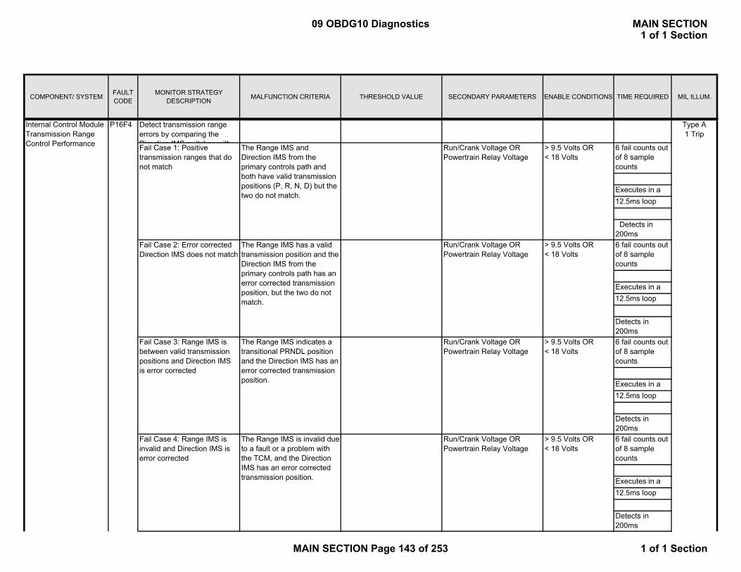
COMPONENT/ SYSTEM FAULT CODE
MONITOR STRATEGY DESCRIPTION MALFUNCTION CRITERIA THRESHOLD VALUE SECONDARY PARAMETERS ENABLE CONDITIONS TIME REQUIRED MIL ILLUM.
6 fail counts out of 8 sample counts
Executes in a12.5ms loop
Detects in 200ms6 fail counts out of 8 sample counts
Executes in a12.5ms loop
Detects in 200ms6 fail counts out of 8 sample counts
Executes in a12.5ms loop
Detects in 200ms6 fail counts out of 8 sample counts
Executes in a12.5ms loop
Detects in 200ms
Internal Control Module Transmission Range Control Performance
P16F4
Fail Case 4: Range IMS is invalid and Direction IMS is error corrected
The Range IMS is invalid due to a fault or a problem with the TCM, and the Direction IMS has an error corrected transmission position.
Run/Crank Voltage OR Powertrain Relay Voltage
> 9.5 Volts OR < 18 Volts
Type A 1 Trip
Fail Case 1: Positive transmission ranges that do not match
The Range IMS and Direction IMS from the primary controls path and both have valid transmission positions (P, R, N, D) but the two do not match.
Run/Crank Voltage OR Powertrain Relay Voltage
> 9.5 Volts OR < 18 Volts
Fail Case 2: Error corrected Direction IMS does not match
The Range IMS has a valid transmission position and the Direction IMS from the primary controls path has an error corrected transmission position, but the two do not match.
Detect transmission range errors by comparing the Direction IMS switches with
> 9.5 Volts OR < 18 Volts
Fail Case 3: Range IMS is between valid transmission positions and Direction IMS is error corrected
The Range IMS indicates a transitional PRNDL position and the Direction IMS has an error corrected transmission position.
Run/Crank Voltage OR Powertrain Relay Voltage
Run/Crank Voltage OR Powertrain Relay Voltage
> 9.5 Volts OR < 18 Volts
09 OBDG10 Diagnostics MAIN SECTION1 of 1 Section
MAIN SECTION Page 143 of 253 1 of 1 Section

COMPONENT/ SYSTEM FAULT CODE
MONITOR STRATEGY DESCRIPTION MALFUNCTION CRITERIA THRESHOLD VALUE SECONDARY PARAMETERS ENABLE CONDITIONS TIME REQUIRED MIL ILLUM.
6 fail counts out of 8 sample counts
Executes in a12.5ms loop
Detects in 200ms6 fail counts out of 8 sample counts
Executes in a12.5ms loop
Detects in 200ms
Does not run during shutdown test (see P16F9)
4 fail counts out of 6 sample counts
Detects in 200ms
The Transmission Range State monitor verifies that there are no mismatches in system equations, the transmission range state being executed is valid, and the transmission range state has not performed an invalid transition
Type A 1 Trip
Internal Control Module Programmable Logic Device
P16F5 The main processor monitor rings tests the capability of the PLD to detect any incorrect keys.
Internal Control Module Commanded Range State
P16F6
> 9.5 Volts OR < 18 Volts
The hardwired signal that is from the PLD indicates receipt of a correct key when the main processor monitor deliberately sends bad keys
Type A 1 Trip
Executes in a 12.5 ms LoopRun/Crank Voltage OR
Powertrain Relay Voltage> 9.5 Volts OR < 18 Volts
The Range IMS is invalid due to a fault or a problem with the TCM, and the Direction IMS is invalid due to a fault or a problem with the HCP
Run/Crank Voltage OR Powertrain Relay Voltage
Run/Crank Voltage OR Powertrain Relay Voltage
> 9.5 Volts OR < 18 Volts
The Range IMS indicates a transitional PRNDL position and the Direction IMS is invalid due to a fault or a problem with the HCP
Fail Case 6: Range IMS and Direction IMS are both invalid
Fail Case 5: Range IMS is between valid transmission positions and Direction IMS is invalid
09 OBDG10 Diagnostics MAIN SECTION1 of 1 Section
MAIN SECTION Page 144 of 253 1 of 1 Section

COMPONENT/ SYSTEM FAULT CODE
MONITOR STRATEGY DESCRIPTION MALFUNCTION CRITERIA THRESHOLD VALUE SECONDARY PARAMETERS ENABLE CONDITIONS TIME REQUIRED MIL ILLUM.
1 failure
Detected within 25ms of failure
1 failure
Detected within 25ms of failure
1 failure
Detected within 25ms of failure
1 failure
Detected within 25ms of failure
1 failure
Detected within 25ms of failure
1 failure
Detected within 25ms of failure
1. Ignition Key Status OFFHigh Voltage Contactor Status OPEN
Type A 1 Trip
The main processor monitor ring is testing the ability of the PLD to detect a seed/key error and take necessary action
The Input Torque Optimization State can not be rationalized against the current Transmission Range State
Internal Control Module Shutdown Performance
P16F9
Fail Case 1: Invalid Transmission Range State
Fail Case 1: Monitor MCPA for shutdown path test passed
Fail Case 6: Input Torque Optimization State mismatches current Transmission Range State
Runs continuously
Fail Case 2: Invalid Transmission Range State Group
Runs continuously
The Range Equation can not be rationalized against the current Transmission Range State.
Executes in a 12.5 ms Loop
Runs continuously
The CAN signal that is from MCPA indicates test status equals failed
A value of 1 at test startup or a value of 0 at the end of test would fail
Runs continuously
Fail Case 5: Torque Determination State mismatches current Transmission Range State
The Torque Determination State can not be rationalized against the current Transmission Range State.
Runs continuously
The current Transmission Range State being used by the system is detected to be an invalid value within the current Transmission Range State Group.
The current Transmission Range State Group being used by the system is an invalid value.
Runs continuously
Fail Case 4: Range Equation mismatches current Transmission Range State
Fail Case 3: Invalid Transmission Range State transition
The current Transmission Range State has changed, and the change in value is not one of the supported transitions from the previous Transmission Range State.
09 OBDG10 Diagnostics MAIN SECTION1 of 1 Section
MAIN SECTION Page 145 of 253 1 of 1 Section

COMPONENT/ SYSTEM FAULT CODE
MONITOR STRATEGY DESCRIPTION MALFUNCTION CRITERIA THRESHOLD VALUE SECONDARY PARAMETERS ENABLE CONDITIONS TIME REQUIRED MIL ILLUM.
AND
P16F9 StatusTest Failed on Previous Key Cycle
Detects in 350ms
1. Ignition Key Status OFFHigh Voltage Contactor Status OPEN
AND
P16F9 StatusTest Failed on Previous Key Cycle
Detects in 350ms
The current alive rolling count value does not equal the previous alive rolling count value incremented by 1
Current ARC ≠ Previous ARC +1
Ignition Key Status Run/Crank for > 0.5 s
5 fail counts out of 8 sample counts
The primary value does not equal the protection value
Primary Value ≠ Protection Value
Detects in 200ms
High voltage bus disccharge time too long
Failed discharge after key off:
> 200 V 2 consecutive failed discharge events (250ms each event)
Discharge time > 500 msFailed discharge count ≥ 2
Battery Pack Diagnostics
2. Ignition Key Status Run/Crank
2. Ignition Key Status Run/Crank
Fail Case 2: Monitor MCPB for shutdown path test passed
Type A 1 Trip
Executes in a 12.5 ms Loop
The SPI signal that is from MCPB indicates test status equals failed
A value of 1 at test startup or a value of 0 at the end of test would fail
Executes in a 12.5 ms Loop
Alive Rolling Count / Protection Value fault for the Transfer case range (4WD Hi-Lo-Neutral)
P279D Detect the ARC (Alive Rolling Count) or Protection Value fault by checking the ARC and Protection Value of the Transfer case range (4WD Hi-Lo-Neutral)
Special Type C No MIL
P0C76Hybrid Battery System Discharge Time Too Long
09 OBDG10 Diagnostics MAIN SECTION1 of 1 Section
MAIN SECTION Page 146 of 253 1 of 1 Section

COMPONENT/ SYSTEM FAULT CODE
MONITOR STRATEGY DESCRIPTION MALFUNCTION CRITERIA THRESHOLD VALUE SECONDARY PARAMETERS ENABLE CONDITIONS TIME REQUIRED MIL ILLUM.
P0A7E High voltage battery overtemperature
Battery temperature > 73°C 5 minutes(3000 fail / 3600 sample; 100ms frequency)
Hybrid Battery Contactor Control Sequence Incorrect
P1A21 Contactor control functionality
Contactors closed this key on&Shutdown in process&Battery contactor state
= TRUE
= FALSE
≠ CLOSED
50 ms Type A 1 Trip
Hybrid System Performance
P0AB9 This diagnostic indicates an autostart or autostop attempt failed.
A problem during the autostart/stop process causes the engine to stall.
12.5 ms Type A 1 Trip
Control Module Communication Bus A Off
U0073 Detects that a CAN serial data bus shorted condition has occurred to force the CAN device driver to enter a bus-off state.
CAN device driver = bus-off state.
Run/Crank Voltage OR Powertrain Relay Voltage
> 9.5 Volts OR < 18 Volts
3 failures out of 5 samples
Detects in 450 msec at loop rate of 12.5
msec
Type A 1 Trip
Control Module Communication Bus B Off
U0074 Detects that a CAN serial data bus shorted condition has occurred to force the CAN device driver to enter a bus-off state.
CAN device driver = bus-off state.
Run/Crank Voltage OR Powertrain Relay Voltage
> 9.5 Volts OR < 18 Volts
3 failures out of 5 samples
Detects in 450 msec at loop rate of 12.5
msec
Type A 1 Trip
Lost Communication With ECM/PCM on Bus A
U0100 Detects that CAN serial data communication has been lost with the ECM on Bus A
Missed ECM MessagesRun/Crank Voltage OR Powertrain Relay Voltage
> 9.5 Volts OR < 18 Volts
Detects within 500 msec at
6.25 msec loop rate
Type A 1 Trip
Lost Communication With ECM/PCM on Bus B
U1818 Detects that CAN serial data communication has been lost with the ECM on Bus B
Missed ECM MessagesRun/Crank Voltage OR Powertrain Relay Voltage
> 9.5 Volts OR < 18 Volts
Detects within 500 msec at
6.25 msec loop rate
Type A 1 Trip
Autostart Diagnostics
Communication Diagnostics
Special Type C No MIL
Hybrid Battery Pack Overtemperature
09 OBDG10 Diagnostics MAIN SECTION1 of 1 Section
MAIN SECTION Page 147 of 253 1 of 1 Section

COMPONENT/ SYSTEM FAULT CODE
MONITOR STRATEGY DESCRIPTION MALFUNCTION CRITERIA THRESHOLD VALUE SECONDARY PARAMETERS ENABLE CONDITIONS TIME REQUIRED MIL ILLUM.
Lost Communication With TCM
U0101 Detects that CAN serial data communication has been lost with the ECM on Bus A
Missed TCM MessagesRun/Crank Voltage OR Powertrain Relay Voltage
> 9.5 Volts OR < 18 Volts
Detects within 500 msec at
6.25 msec loop rate
Type A 1 Trip
Lost Communication With Transfer Case Control Module(supported when applicable)
U0102 Detects that CAN serial data communication has been lost with the TCCM on Bus A
Missed TCCM Messages Ignition switchSystem Voltage
Run10 V to 18 V
Detects within 500 msec at
6.25 msec loop rate
Type B 2 Trips
Lost Communication With Brake System Control Module
U0129 Detects that CAN serial data communication has been lost with the EBCM on Bus A
Missed EBCM Messages Ignition switchSystem Voltage
Run10 V to 18 V
Detects within 500 msec at
6.25 msec loop rate
Type B 2 Trips
Lost Communication With Motor Control Processor on Bus B
U1815 Detects that CAN serial data communication has been lost with the MCPA on Bus B
Missed MCPA Messages Ignition switchSystem Voltage
Run10 V to 18 V
Detects within 500 msec at
6.25 msec loop rate
Type B 2 Trips
Lost Communication With Battery Pack Control Module
U1888 Detects that CAN serial data communication has been lost with the BPCM
Missed BPCM MessagesRun/Crank Voltage OR Powertrain Relay Voltage
> 9.5 Volts OR < 18 Volts
Detects within 500 msec at
6.25 msec loop rate
Type A 1 Trip
09 OBDG10 Diagnostics MAIN SECTION1 of 1 Section
MAIN SECTION Page 148 of 253 1 of 1 Section
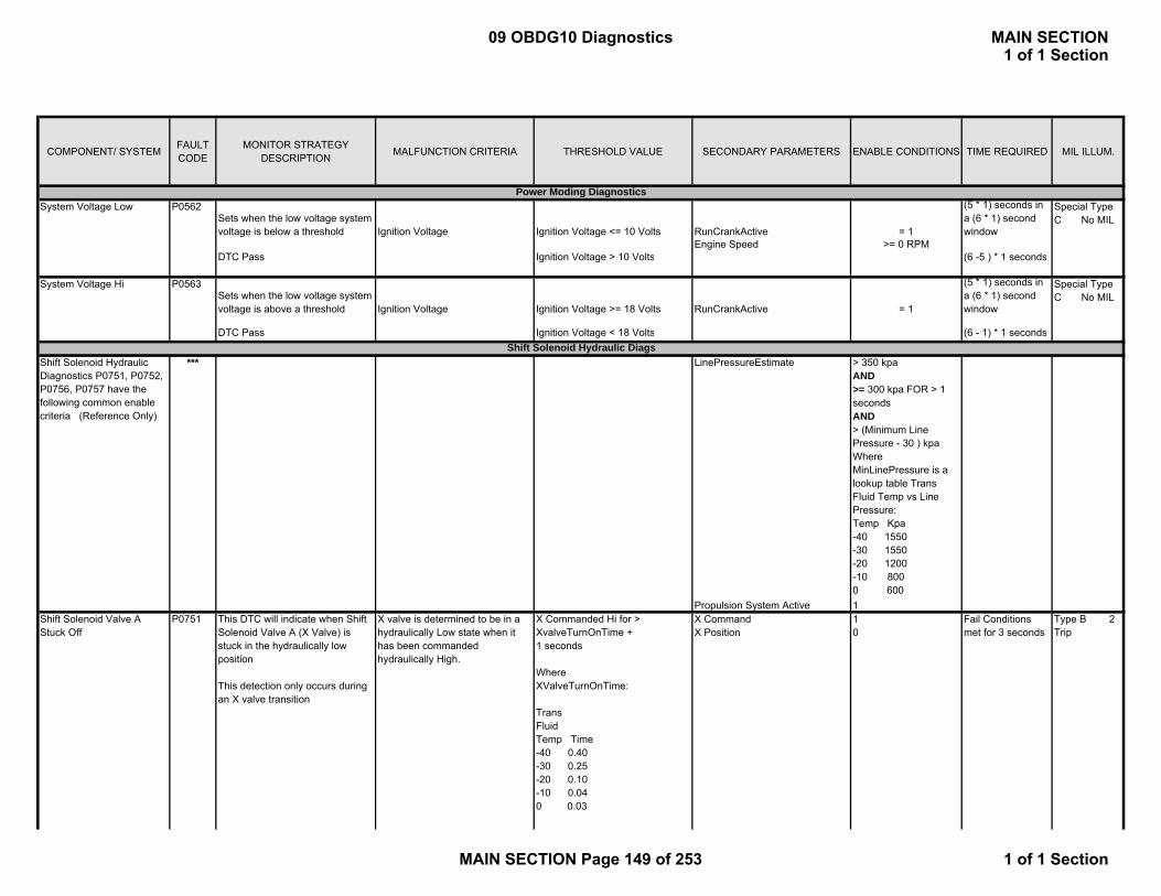
COMPONENT/ SYSTEM FAULT CODE
MONITOR STRATEGY DESCRIPTION MALFUNCTION CRITERIA THRESHOLD VALUE SECONDARY PARAMETERS ENABLE CONDITIONS TIME REQUIRED MIL ILLUM.
Sets when the low voltage system voltage is below a threshold Ignition Voltage Ignition Voltage <= 10 Volts RunCrankActive = 1
(5 * 1) seconds in a (6 * 1) second window
Engine Speed >= 0 RPMDTC Pass Ignition Voltage > 10 Volts (6 -5 ) * 1 seconds
Sets when the low voltage system voltage is above a threshold Ignition Voltage Ignition Voltage >= 18 Volts RunCrankActive = 1
(5 * 1) seconds in a (6 * 1) second window
DTC Pass Ignition Voltage < 18 Volts (6 - 1) * 1 seconds
*** LinePressureEstimate > 350 kpaAND>= 300 kpa FOR > 1 secondsAND> (Minimum Line Pressure - 30 ) kpaWhere MinLinePressure is a lookup table Trans Fluid Temp vs Line Pressure:Temp Kpa-40 1550-30 1550-20 1200-10 8000 600
Propulsion System Active 1This DTC will indicate when Shift Solenoid Valve A (X Valve) is stuck in the hydraulically low position
This detection only occurs during an X valve transition
X valve is determined to be in a hydraulically Low state when it has been commanded hydraulically High.
X Commanded Hi for > XvalveTurnOnTime + 1 seconds
WhereXValveTurnOnTime:
TransFluidTemp Time-40 0.40-30 0.25-20 0.10-10 0.040 0.03140 0 02
X CommandX Position
10
Fail Conditions met for 3 seconds
Special Type C No MIL
Shift Solenoid Hydraulic Diagnostics P0751, P0752, P0756, P0757 have the following common enable criteria (Reference Only)
System Voltage Hi P0563
Power Moding Diagnostics
Shift Solenoid Hydraulic Diags
System Voltage Low P0562 Special Type C No MIL
Shift Solenoid Valve A Stuck Off
P0751 Type B 2 Trip
09 OBDG10 Diagnostics MAIN SECTION1 of 1 Section
MAIN SECTION Page 149 of 253 1 of 1 Section

COMPONENT/ SYSTEM FAULT CODE
MONITOR STRATEGY DESCRIPTION MALFUNCTION CRITERIA THRESHOLD VALUE SECONDARY PARAMETERS ENABLE CONDITIONS TIME REQUIRED MIL ILLUM.
P M di Di iDTC Pass X valve completes Low to High
transition without failureX CommandX Position
11
1 loop execution at 0.0125 seconds
This DTC will indicate when Shift Solenoid Valve A (X Valve) is stuck in the hydraulically hi position
This DTC is linked to both a steady state and transitional test.
X valve is determined to be in a hydraulically high state when it has been commanded to a low state.
Transition Case: X commanded Low for > (XvalveTurnOffTm + 1) seconds
WhereXValveTurnOffTime:
TransFluidTemp Time-40 0.50-30 0.40-20 0.12-10 0.080 0.03140 0.0325
X CommandX Position
01
Fail Conditions met for 3 seconds
DTC Pass (Transitional Pass) X valve completes High to Low transition without failure
X CommandX positionPCS2 and PCS4 Monitors
00No Fault Pending
5 seconds
XY state EVT Lo OR EVT Hi Fail Conditions met for 2 seconds
PCS2 and PCS4 faults Occur Simultaneously -within (VlvXStckHiSteadyStWindow + 0.1 ) seconds
WhereVlvXStckHiSteadyStWindow:
TransFluidTemp Time-50 0.50-32 0.50-24 0.50-5 0.504 0.5040 0.50
P0752Shift Solenoid Valve A Stuck On
Type B 2 Trip
Steady State Case: Simultaneous failures occur on both PCS2 and PCS4 monitors
09 OBDG10 Diagnostics MAIN SECTION1 of 1 Section
MAIN SECTION Page 150 of 253 1 of 1 Section

COMPONENT/ SYSTEM FAULT CODE
MONITOR STRATEGY DESCRIPTION MALFUNCTION CRITERIA THRESHOLD VALUE SECONDARY PARAMETERS ENABLE CONDITIONS TIME REQUIRED MIL ILLUM.
P M di Di iDTC Pass (Steady State Pass) X valve completes High to Low transition without failure
X CommandX positionPCS2 and PCS4 Monitors
00No Fault Pending
5 seconds
PCS4 hydraulic stuck high failure detected upon key up
TRUE Fail conditions met for > 1800 seconds
XY state EVT LoX commanded high this key cycle FALSE
This DTC will indicate when Shift Solenoid Valve B (Y Valve) is stuck in the hydraulically low position
This detection only occurs during an Y valve transition
The Y valve is determined to be in a hydraulically Low state when it has been commanded hydraulically High.
Y Commanded Hi for > (Yvalve_TurnOnTm + 1 seconds
WhereYvalve_TurnOnTm:
TransFluidTemp Time-40 0.90-30 0.60-20 0.28-10 0.2020 0.05140 0.035
Y CommandY Position
10
Fail Conditions met for 4.5 seconds
DTC Pass Y valve completes Low to High transition without failure
Y command Y Position
11 (as indicated by YPSw showing 0 value)
Pass conditions met for 2 seconds
This DTC will indicate when Shift Solenoid Valve B (Y Valve) is stuck in the hydraulically hi position
This detection only occurs during an Y valve transition
The Y valve is determined to be in a hydraulically Hi state when it has been commanded hydraulically Lo
Y Commanded Lo for > (Yvalve_TurnOffTm + 1) seconds
WhereYvalve_TurnOffTm:
TransFluidTemp Time-40 2.17-30 1.35-20 0.54-10 0.2020 0.064140 0.05
Y CommandY Position
01
Fail Conditions met for 4.5 seconds
Type B 2 Trip
Type A 1 Trip
Stuck In Bore Case: X stuck in bore detection is indeterminant for an extended period of time
Shift Solenoid Valve B Stuck On
P0757
Shift Solenoid Valve B Stuck Off
P0756
09 OBDG10 Diagnostics MAIN SECTION1 of 1 Section
MAIN SECTION Page 151 of 253 1 of 1 Section

COMPONENT/ SYSTEM FAULT CODE
MONITOR STRATEGY DESCRIPTION MALFUNCTION CRITERIA THRESHOLD VALUE SECONDARY PARAMETERS ENABLE CONDITIONS TIME REQUIRED MIL ILLUM.
P M di Di iDTC Pass Y valve completes High to Low transition without failure
Y CommandY Position
00 (as indicated by YPSw showing 1 value)
Pass conditions met for 2 seconds
Engine speed (> 550 RPM FOR > 100 * .0125 seconds) OR (<= 50 RPM FOR 110 * 0.0125 seconds)
Xvalve transition X valve s not in a transition, and hasn’t transitioned in the last (0.025 + .25) seconds
X Valve Stuck Hi Detection No fault pendingLinePressureEstimate > 350 kpa
AND>= 300 kpa FOR > 1 secondsAND> (MinLinePressure - 30 ) kpa
Where MinLinePressure is a lookup table TransTemp vs Line Pressure:Temp Kpa-40 1550-30 1550-20 1200-10 8000 600
Propulsion System Active 1
***Pressure Control Solenoid hydraulic diagnostics P0776, P0777, P0796, P0797 P2714, P2715, share these common secondary parameter enable conditions (Reference Only)
Pressure Control Solenoid Hydraulic Diagnostics
09 OBDG10 Diagnostics MAIN SECTION1 of 1 Section
MAIN SECTION Page 152 of 253 1 of 1 Section

COMPONENT/ SYSTEM FAULT CODE
MONITOR STRATEGY DESCRIPTION MALFUNCTION CRITERIA THRESHOLD VALUE SECONDARY PARAMETERS ENABLE CONDITIONS TIME REQUIRED MIL ILLUM.
P M di Di iThis DTC will determine if Pressure Control Solenoid 2 (B) is stuck in the hydraulically low position. This DTC has two fail cases.
The pressure switch associated with pressure control solenoid B (PCS2) is indicating that the PCS is regulating exhuast when the PCS has been commanded full feed.
Fail Case 1: PCS2PS (PSw3) indicates low hydraulic pressure
PCS commanded pressure
*** Common Hydraulic Enables
>= 1800 kpa for >= (PSReDelay + 0.1) seconds
WherePSReDelay:
FluidTemp Time-50 4.50-30 1.80-24 1.2-17 0.804 0.2040 0 1
Failure exisits for (2400 * 0.0125) seconds
DTC Pass Pass when PCS2PS and PCS2Cmnd are in agreement (Full Feed)
PCS2PS (PSw3) indicates hi hydraulic pressure
(2500 - 2400) * 0.0125 seconds
The warning threshold for Fail Case 1 has been met 5 times in a single key cycle
Fail Case 2: Fail case 1 criteria met for atleast (40 * 0.0125) seconds, more than 5 times in a given key cycle
Same as Fail Case 1. N/A
This DTC will determine if Pressure Control Solenoid 2 (B) is stuck in the hydraulically hi position. This DTC has two fail cases.
Tthe pressure switch associated with pressure control solenoid B (PCS2) is indicating that the PCS is in the full feed position when the PCS has been commanded regulating exhaust.
Fail Case 1: PCS2PS (PSw3) indicates hi hydraulic pressure
PCS commanded pressure
*** Common Hydraulic Enables
<= 5 kpa for >= (FFDelay + 0.1) seconds
WhereFFDelay:
Temp Time-50 4.50-30 1.40-18 0.80-4 0.3013 0.1940 0 08
Failure exisits for (2400 * 0.0125) seconds
DTC Pass Pass when PCS2PS and PCS2Cmnd are in agreement (Reg Exhaust)
PCS2PS (PSw3) indicates Low hydraulic pressure
(2500 - 2400) * 0.0125 seconds
The warning threshold for Fail Case 1 has been met 5 times in a single key cycle
Fail Case 2: Fail case 1 criteria met for atleast (16 * 0.0125) seconds, more than 5 times in a given key cycle
Same as Fail Case 1. N/A
Pressure Control (PC) Solenoid B Stuck ON
P0777
Pressure Control (PC) Solenoid B Stuck Off
P0776 Type B 2 Trip
Type B 2 Trip
09 OBDG10 Diagnostics MAIN SECTION1 of 1 Section
MAIN SECTION Page 153 of 253 1 of 1 Section

COMPONENT/ SYSTEM FAULT CODE
MONITOR STRATEGY DESCRIPTION MALFUNCTION CRITERIA THRESHOLD VALUE SECONDARY PARAMETERS ENABLE CONDITIONS TIME REQUIRED MIL ILLUM.
P M di Di iThis DTC will determine if Pressure Control Solenoid 3 (C) is stuck in the hydraulically low position. This DTC has two fail cases.
The pressure switch associated with pressure control solenoid C (PCS3) is indicating that the PCS is regulating exhuast when the PCS has been commanded full feed.
Fail Case 1: PCS3PS (PSw1) indicates low hydraulic pressure
PCS commanded pressure
*** Common Hydraulic Enables
>= 1800 kpa for >= (PSReDelay + 0.1) seconds
WherePSReDelay:
Temp Time-50 4.50-30 1.80-24 1.2-17 0.804 0.2040 0.1
Failure exisits for (2400 * 0.0125) seconds
DTC Pass Pass when PCS3PS and PCS3Cmnd are in agreement (Full Feed)
PCS3PS (PSw1) indicates hi hydraulic pressure
(2500 - 2400) * 0.0125 seconds
The warning threshold for Fail Case 1 has been met 5 times in a single key cycle
Fail Case 2: Fail case 1 criteria met for atleast for atleast (40 * 0.0125) seconds, more than 5 times in a given key cycle
Same as Fail Case 1. N/A
This DTC will determine if Pressure Control Solenoid 3 (C) is stuck in the hydraulically hi position. This DTC has two fail cases.
The pressure switch associated with pressure control solenoid C (PCS3) is indicating that the PCS is in the full feed position when the PCS has been commanded regulating exhaust.
Fail Case 1: PCS3PS (PSw1) indicates hi hydraulic pressure
PCS commanded pressure <=
*** Common Hydraulic Enables
5 kpa for >= (FFDelay + 0.1) seconds
WhereFFDelay:
TransFluidTemp Time-50 4.50-30 1.40-18 0.80-4 0.3013 0.1940 0.08
Failure exisits for (2400 * 0.0125) seconds
DTC Pass Pass when PCS3PS and PCS3Cmnd are in agreement (Reg Exhaust)
PCS3PS (PSw1) indicates Low hydraulic pressure
(2500 - 2400) * 0.0125 seconds
The warning threshold for Fail Case 1 has been met 5 times in a single key cycle
Fail Case 2: Fail case 1 criteria met for atleast (16 * 0.0125) seconds, more than 5 times in a given key cycle
Same as Fail Case 1. N/A
Pressure Control (PC) Solenoid C Stuck Off
P0796
Pressure Control (PC) Solenoid C Stuck ON
P0797
Type B 2 Trip
Type B 2 Trip
09 OBDG10 Diagnostics MAIN SECTION1 of 1 Section
MAIN SECTION Page 154 of 253 1 of 1 Section
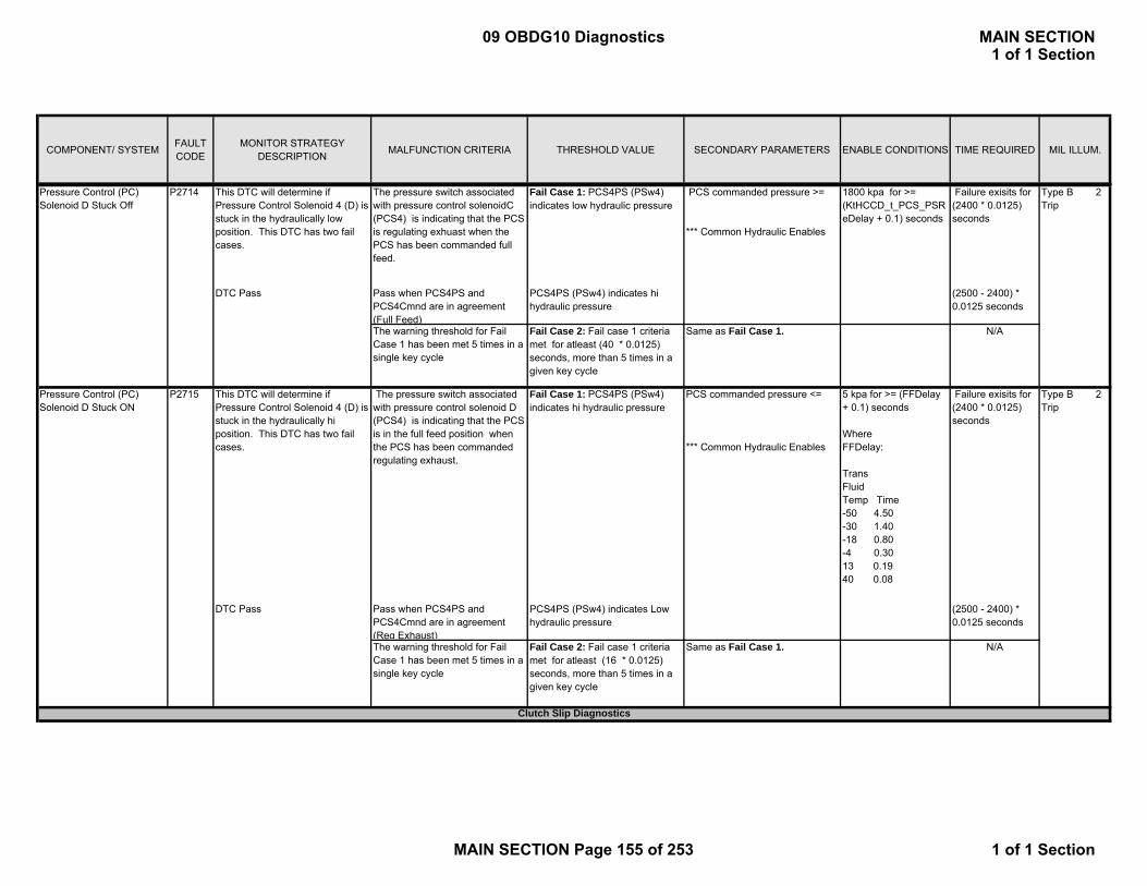
COMPONENT/ SYSTEM FAULT CODE
MONITOR STRATEGY DESCRIPTION MALFUNCTION CRITERIA THRESHOLD VALUE SECONDARY PARAMETERS ENABLE CONDITIONS TIME REQUIRED MIL ILLUM.
P M di Di iThis DTC will determine if Pressure Control Solenoid 4 (D) is stuck in the hydraulically low position. This DTC has two fail cases.
The pressure switch associated with pressure control solenoidC (PCS4) is indicating that the PCS is regulating exhuast when the PCS has been commanded full feed.
Fail Case 1: PCS4PS (PSw4) indicates low hydraulic pressure
PCS commanded pressure >=
*** Common Hydraulic Enables
1800 kpa for >= (KtHCCD_t_PCS_PSReDelay + 0.1) seconds
Failure exisits for (2400 * 0.0125) seconds
DTC Pass Pass when PCS4PS and PCS4Cmnd are in agreement (Full Feed)
PCS4PS (PSw4) indicates hi hydraulic pressure
(2500 - 2400) * 0.0125 seconds
The warning threshold for Fail Case 1 has been met 5 times in a single key cycle
Fail Case 2: Fail case 1 criteria met for atleast (40 * 0.0125) seconds, more than 5 times in a given key cycle
Same as Fail Case 1. N/A
This DTC will determine if Pressure Control Solenoid 4 (D) is stuck in the hydraulically hi position. This DTC has two fail cases.
The pressure switch associated with pressure control solenoid D (PCS4) is indicating that the PCS is in the full feed position when the PCS has been commanded regulating exhaust.
Fail Case 1: PCS4PS (PSw4) indicates hi hydraulic pressure
PCS commanded pressure <=
*** Common Hydraulic Enables
5 kpa for >= (FFDelay + 0.1) seconds
WhereFFDelay:
TransFluidTemp Time-50 4.50-30 1.40-18 0.80-4 0.3013 0.1940 0.08
Failure exisits for (2400 * 0.0125) seconds
DTC Pass Pass when PCS4PS and PCS4Cmnd are in agreement (Reg Exhaust)
PCS4PS (PSw4) indicates Low hydraulic pressure
(2500 - 2400) * 0.0125 seconds
The warning threshold for Fail Case 1 has been met 5 times in a single key cycle
Fail Case 2: Fail case 1 criteria met for atleast (16 * 0.0125) seconds, more than 5 times in a given key cycle
Same as Fail Case 1. N/A
Pressure Control (PC) Solenoid D Stuck ON
P2715
Pressure Control (PC) Solenoid D Stuck Off
P2714
Type B 2 Trip
Clutch Slip Diagnostics
Type B 2 Trip
09 OBDG10 Diagnostics MAIN SECTION1 of 1 Section
MAIN SECTION Page 155 of 253 1 of 1 Section
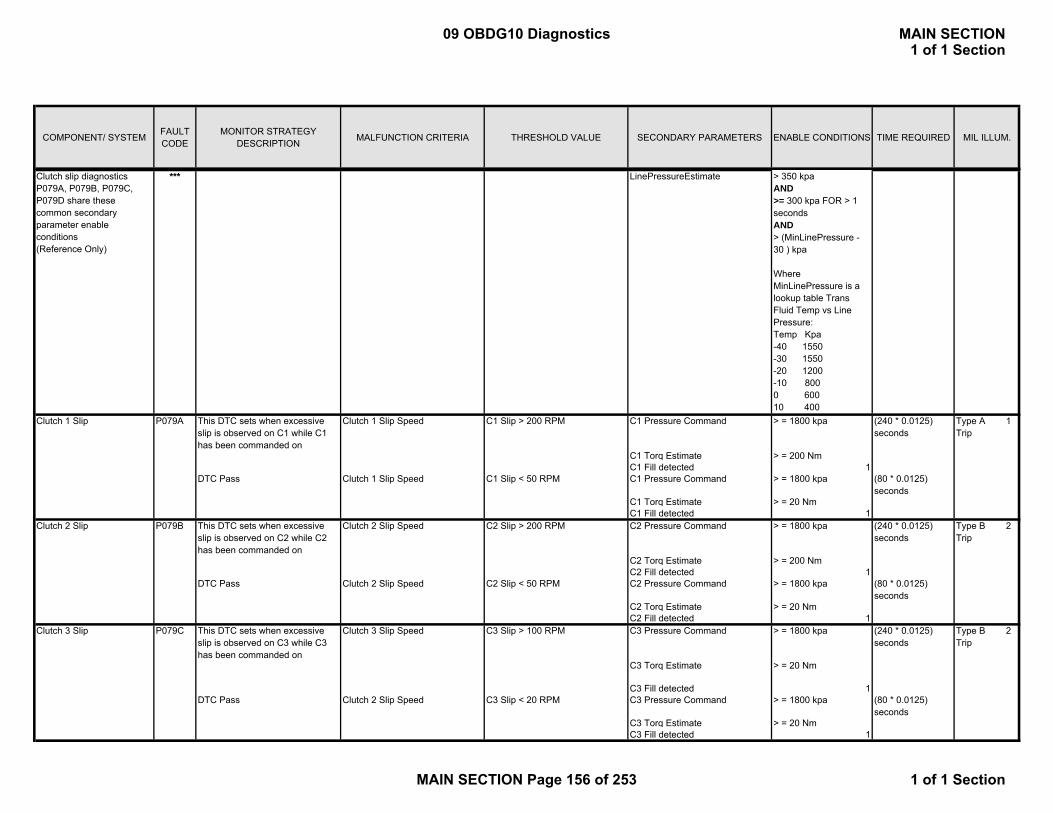
COMPONENT/ SYSTEM FAULT CODE
MONITOR STRATEGY DESCRIPTION MALFUNCTION CRITERIA THRESHOLD VALUE SECONDARY PARAMETERS ENABLE CONDITIONS TIME REQUIRED MIL ILLUM.
P M di Di iClutch slip diagnostics P079A, P079B, P079C, P079D share these common secondary parameter enable conditions (Reference Only)
*** LinePressureEstimate > 350 kpaAND>= 300 kpa FOR > 1 secondsAND> (MinLinePressure - 30 ) kpa
Where MinLinePressure is a lookup table Trans Fluid Temp vs Line Pressure:Temp Kpa-40 1550-30 1550-20 1200-10 8000 60010 400
This DTC sets when excessive slip is observed on C1 while C1 has been commanded on
Clutch 1 Slip Speed C1 Slip > 200 RPM C1 Pressure Command > = 1800 kpa (240 * 0.0125) seconds
C1 Torq Estimate > = 200 NmC1 Fill detected 1
DTC Pass Clutch 1 Slip Speed C1 Slip < 50 RPM C1 Pressure Command > = 1800 kpa (80 * 0.0125) seconds
C1 Torq Estimate > = 20 NmC1 Fill detected 1
This DTC sets when excessive slip is observed on C2 while C2 has been commanded on
Clutch 2 Slip Speed C2 Slip > 200 RPM C2 Pressure Command > = 1800 kpa (240 * 0.0125) seconds
C2 Torq Estimate > = 200 NmC2 Fill detected 1
DTC Pass Clutch 2 Slip Speed C2 Slip < 50 RPM C2 Pressure Command > = 1800 kpa (80 * 0.0125) seconds
C2 Torq Estimate > = 20 NmC2 Fill detected 1
This DTC sets when excessive slip is observed on C3 while C3 has been commanded on
Clutch 3 Slip Speed C3 Pressure Command > = 1800 kpa (240 * 0.0125) seconds
C3 Torq Estimate > = 20 Nm
C3 Fill detected 1DTC Pass Clutch 2 Slip Speed C3 Slip < 20 RPM C3 Pressure Command > = 1800 kpa (80 * 0.0125)
secondsC3 Torq Estimate > = 20 NmC3 Fill detected 1
Clutch 3 Slip P079C
Type A 1 Trip
Type B 2 Trip
Type B 2 Trip
P079A
C3 Slip > 100 RPM
Clutch 2 Slip P079B
Clutch 1 Slip
09 OBDG10 Diagnostics MAIN SECTION1 of 1 Section
MAIN SECTION Page 156 of 253 1 of 1 Section

COMPONENT/ SYSTEM FAULT CODE
MONITOR STRATEGY DESCRIPTION MALFUNCTION CRITERIA THRESHOLD VALUE SECONDARY PARAMETERS ENABLE CONDITIONS TIME REQUIRED MIL ILLUM.
P M di Di iThis DTC sets when excessive slip is observed on C4 while C4 has been commanded on
Clutch 4 Slip Speed C4 Pressure Command > = 1800 kpa (150 * 0.0125) seconds
C4 Torq Estimate > = 20 NmC4 Fill detected 1
DTC Pass Clutch 2 Slip Speed C4 Slip < 20 RPM C4 Pressure Command > = 1800 kpa (80 * 0.0125) seconds
C4 Torq Estimate > = 20 NmC4 Fill detected 1
*** Ignition voltage > = 11 Volts && <= 16 Volts
Engine Speed >= 0 RPM && <= 7500 RPM for >= 5 seconds
Vehicle Speed <= 200 kph for >= 5 seconds
RunCrankActive 1
This DTC sets when an invalid voltage in PCS1 control circuit has been detected
PCS1 electrical status HWIO circutry detects out of range error is present
DTC P0961 Not failed this key on Failure detected for (320 * 0.0125) seconds out of a (400 * 0.0125) second window
*** Common Electrical Enables
DTC Pass HWIO circuitry detects an out of range error is not present
(400 - 320) * 0.0125 seconds
This DTC sets when the PCS1 control circuit has been detected to be shorted to ground
PCS1 electrical status HWIO circuitry detects an electrical low pressure error is present
DTC P0962 Not failed this key on Failure detected for (32 * 0.0125) seconds out of a (40 * 0.0125) second window
*** Common Electrical Enables
DTC Pass HWIO circuitry detects an electrical low pressure error is not present
(40 - 32) * 0.0125 seconds
All Pressure Control Solenoid electrical diagnostics P0961, P0962, P0963, P0965, P0966, P0967, P0969, P0970, P0971, P2719, P2720, P2721, P2728, P2729, P2730, P0973, P0974, P0976, P0977 share these common secondary parameter enable conditions. (Reference Only)
Pressure Control (PC) Solenoid A Control Circuit Low Voltage
P0962
Clutch 4 Slip P079D
Pressure Control Solenoid Electrical Diags
C4 Slip > 100 RPM
Pressure Control (PC) Solenoid A System Performance
P0961
Type B 2 Trip
Type B 2 Trip
Type A 1 Trip
09 OBDG10 Diagnostics MAIN SECTION1 of 1 Section
MAIN SECTION Page 157 of 253 1 of 1 Section

COMPONENT/ SYSTEM FAULT CODE
MONITOR STRATEGY DESCRIPTION MALFUNCTION CRITERIA THRESHOLD VALUE SECONDARY PARAMETERS ENABLE CONDITIONS TIME REQUIRED MIL ILLUM.
P M di Di iThis DTC sets when PCS1 has been detected to be shorted to power or open circuited.
PCS1 electrical status HWIO circuitry detects an electrical hi pressure error is present.
DTC P0963 Not failed this key on Failure detected for (32 * 0.0125) seconds out of a (40 * 0.0125) second window
*** Common Electrical Enables
DTC Pass HWIO circuitry detects an electrical hi pressure error is not present
(40 - 32) * 0.0125 seconds
This DTC sets when an invalid voltage in PCS2 control circuit has been detected
PCS2 electrical status HWIO circutry detects out of range error is present.
DTC P0965 Not failed this key on Failure detected for (320 * 0.0125) seconds out of a (400 * 0.0125) second window
*** Common Electrical Enables
DTC Pass HWIO circuitry detects an out of range error is not present
(400 - 320) * 0.0125 seconds
This DTC sets when the PCS2 control circuit has been detected to be shorted to ground
PCS2 electrical status HWIO circuitry detects an electrical low pressure error is present.
DTC P0966 Not failed this key on Faiilure detected for (32 * 0.0125) seconds out of a (40 * 0.0125) second window
*** Common Electrical Enables
DTC Pass HWIO circuitry detects an electrical low pressure error is not present
(40 - 32) * 0.0125 seconds
This DTC sets when PCS2 has been detected to be shorted to power or open circuited.
PCS2 electrical status HWIO circuitry detects an electrical hi pressure error is present.
DTC P0967 Not failed this key on Failure detected for (32 * 0.0125) seconds out of a (40 * 0.0125) second window
*** Common Electrical Enables
DTC Pass HWIO circuitry detects an electrical hi pressure error is not present
(40 - 32) * 0.0125 seconds
This DTC sets when an invalid voltage in PCS3 control circuit has been detected
PCS3 electrical status HWIO circutry detects out of range error is present.
DTC P0965 Not failed this key on Failure detected for (320 * 0.0125) seconds out of a (400 * 0.0125) second window
Pressure Control (PC) Solenoid B Control Circuit Low Voltage
P0966
Pressure Control (PC) Solenoid B System Performance
P0965
Pressure Control (PC) Solenoid A Control Circuit High Voltage
P0963
Pressure Control (PC) Solenoid C System Performance
P0969
Pressure Control (PC) Solenoid B Control Circuit High Voltage
P0967 Type A 1 Trip
Type B 2 Trip
Type A 1 Trip
Type B 2 Trip
Type A 1 Trip
09 OBDG10 Diagnostics MAIN SECTION1 of 1 Section
MAIN SECTION Page 158 of 253 1 of 1 Section

COMPONENT/ SYSTEM FAULT CODE
MONITOR STRATEGY DESCRIPTION MALFUNCTION CRITERIA THRESHOLD VALUE SECONDARY PARAMETERS ENABLE CONDITIONS TIME REQUIRED MIL ILLUM.
P M di Di i *** Common Electrical Enables
DTC Pass HWIO circuitry detects an out of range error is not present
(400 - 320) * 0.0125 seconds
This DTC sets when the PCS3 control circuit has been detected to be shorted to ground
PCS3 electrical status HWIO circuitry detects an electrical low pressure error is present.
DTC P0966 Not failed this key on Failure detected for (32 * 0.0125) seconds out of a (40 * 0.0125) second window
*** Common Electrical Enables
DTC Pass HWIO circuitry detects an electrical low pressure error is not present
(40 - 32) * 0.0125 seconds
This DTC sets when PCS3 has been detected to be shorted to power or open circuited.
PCS3 electrical status HWIO circuitry detects an electrical hi pressure error is present.
DTC P0967 Not failed this key on Failure detected for (32 * 0.0125) seconds out of a (40 * 0.0125) second window
*** Common Electrical Enables
DTC Pass HWIO circuitry detects an electrical hi pressure error is not present
(40 - 32) * 0.0125 seconds
This DTC sets when an invalid voltage in PCS4 control circuit has been detected
PCS4 electrical status HWIO circutry detects out of range error is present.
DTC P2719 Not failed this key on Failure detected for (320 * 0.0125) seconds out of a (400 * 0.0125) second window
*** Common Electrical Enables
DTC Pass HWIO circuitry detects an out of range error is not present
(400 - 320) * 0.0125 seconds
This DTC sets when the PCS4 control circuit has been detected to be open circuit or shorted to power
PCS4 electrical status HWIO circuitry detects an electrical low pressure error is present.
DTC P2720 Not failed this key on Failure detected for (32 * 0.0125) seconds out of a (40 * 0.0125) second window
*** Common Electrical Enables
DTC Pass HWIO circuitry detects an electrical low pressure error is not present
(40 - 32) * 0.0125 seconds
Pressure Control (PC) Solenoid D System Performance
P2719
Pressure Control (PC) Solenoid C Control Circuit High Voltage
P0971
Pressure Control (PC) Solenoid C Control Circuit Low Voltage
P0970
Pressure Control (PC) Solenoid D Control Circuit Low Voltage
P2720
Type A 1 Trip
Type A 1 Trip
Type B 2 Trip
Type A 1 Trip
09 OBDG10 Diagnostics MAIN SECTION1 of 1 Section
MAIN SECTION Page 159 of 253 1 of 1 Section
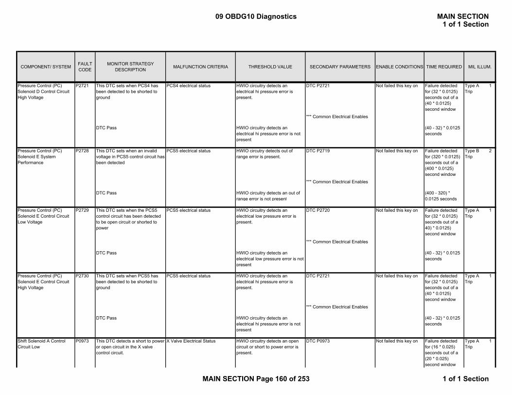
COMPONENT/ SYSTEM FAULT CODE
MONITOR STRATEGY DESCRIPTION MALFUNCTION CRITERIA THRESHOLD VALUE SECONDARY PARAMETERS ENABLE CONDITIONS TIME REQUIRED MIL ILLUM.
P M di Di iThis DTC sets when PCS4 has been detected to be shorted to ground
PCS4 electrical status HWIO circuitry detects an electrical hi pressure error is present.
DTC P2721 Not failed this key on Failure detected for (32 * 0.0125) seconds out of a (40 * 0.0125) second window
*** Common Electrical Enables
DTC Pass HWIO circuitry detects an electrical hi pressure error is not present
(40 - 32) * 0.0125 seconds
This DTC sets when an invalid voltage in PCS5 control circuit has been detected
PCS5 electrical status HWIO circutry detects out of range error is present.
DTC P2719 Not failed this key on Failure detected for (320 * 0.0125) seconds out of a (400 * 0.0125) second window
*** Common Electrical Enables
DTC Pass HWIO circuitry detects an out of range error is not present
(400 - 320) * 0.0125 seconds
This DTC sets when the PCS5 control circuit has been detected to be open circuit or shorted to power
PCS5 electrical status HWIO circuitry detects an electrical low pressure error is present.
DTC P2720 Not failed this key on Failure detected for (32 * 0.0125) seconds out of a 40) * 0.0125) second window
*** Common Electrical Enables
DTC Pass HWIO circuitry detects an electrical low pressure error is not present
(40 - 32) * 0.0125 seconds
This DTC sets when PCS5 has been detected to be shorted to ground
PCS5 electrical status HWIO circuitry detects an electrical hi pressure error is present.
DTC P2721 Not failed this key on Failure detected for (32 * 0.0125) seconds out of a (40 * 0.0125) second window
*** Common Electrical Enables
DTC Pass HWIO circuitry detects an electrical hi pressure error is not present
(40 - 32) * 0.0125 seconds
This DTC detects a short to power or open circuit in the X valve control circuit.
X Valve Electrical Status HWIO circuitry detects an open circuit or short to power error is present.
DTC P0973 Not failed this key on Failure detected for (16 * 0.025) seconds out of a (20 * 0.025) second window
Pressure Control (PC) Solenoid E Control Circuit High Voltage
P2730
Pressure Control (PC) Solenoid E System Performance
P2728
Pressure Control (PC) Solenoid D Control Circuit High Voltage
P2721
Pressure Control (PC) Solenoid E Control Circuit Low Voltage
P2729
Shift Solenoid A Control Circuit Low
P0973
Type A 1 Trip
Type A 1 Trip
Type A 1 Trip
Type B 2 Trip
Type A 1 Trip
09 OBDG10 Diagnostics MAIN SECTION1 of 1 Section
MAIN SECTION Page 160 of 253 1 of 1 Section

COMPONENT/ SYSTEM FAULT CODE
MONITOR STRATEGY DESCRIPTION MALFUNCTION CRITERIA THRESHOLD VALUE SECONDARY PARAMETERS ENABLE CONDITIONS TIME REQUIRED MIL ILLUM.
P M di Di i *** Common Electrical Enables
DTC Pass HWIO circuitry detects an open circuit or short to power error is not present.
(20 - 16) * 0.025 seconds
This DTC detects a short to ground in the X valve control circuit.
X Valve Electrical Status HWIO circuitry detects short to ground error is present.
DTC P0974 Not failed this key on Failure detected for (16 * 0.025) seconds out of a (20 * 0.025) second window
*** Common Electrical Enables
DTC Pass HWIO circuitry detects short to ground error is not present.
(20 - 16) * 0.025 seconds
This DTC detects a short to power or open circuit in the Y valve control circuit.
Y Valve Electrical Status HWIO circuitry detects an electrical low pressure error is present.
DTC P0976 Not failed this key on Failure detected for (16 * 0.025) seconds out of a (20 * 0.025) second window
*** Common Electrical Enables
DTC Pass HWIO circuitry detects an open circuit or short to power error is not present.
(20 - 16) * 0.025 seconds
This DTC detects a short to ground in the Y valve control circuit.
Y Valve Electrical Status HWIO circuitry detects an electrical hi pressure error is present.
DTC P0977 Not failed this key on Failure detected for (16 * 0.025) seconds out of a (20 * 0.025) second window
*** Common Electrical Enables
DTC Pass HWIO circuitry detects short to ground error is not present.
(20 - 16) * 0.025 seconds
Detects a run crank relay open circuit Runk Crank Line voltage
Ignition Run Crank line voltage <= 2 Volts CAN Communication enabled
(2400 * 0.025) seconds in a (2600 * 0.025) second window
ECM run crank active data available and active
DTC Pass Run Crank Line VoltageIgnition Run Crank line voltage > 2 Volts
(215 - 200) * 0.025 seconds
The DTC detects if the transmission fluid temperature is too high.
Transmission Sump Temperature ≥ 135 °C Transmission Temperature -50 °C ≤ TFT ≤ 150 °C for 10 seconds
≥ 300 seconds Type B 2 Trip
Shift Solenoid B Control Circuit High
P0977
Shift Solenoid B Control Circuit Low
P0976
Shift Solenoid A Control Circuit High
P0974
Transmission Fluid Thermostat
Type A 1 Trip
Type A 1 Trip
Transmission Fluid Overtemperature
P0218
Ignition Switch Run/Start Position Circuit Low
P2534
Type A 1 Trip
Type A 1 Trip
09 OBDG10 Diagnostics MAIN SECTION1 of 1 Section
MAIN SECTION Page 161 of 253 1 of 1 Section

COMPONENT/ SYSTEM FAULT CODE
MONITOR STRATEGY DESCRIPTION MALFUNCTION CRITERIA THRESHOLD VALUE SECONDARY PARAMETERS ENABLE CONDITIONS TIME REQUIRED MIL ILLUM.
P M di Di i Ignition Voltage 11 ≤ Ignition Voltage ≤ 18 V
Pass Conditions: Transmission Sump Temperature ≤ 135 °C for 130 seconds
The DTC detects the electronic circuitry is at high operating temperature.
Transmission Substrate Temperature
≥ 142 °C Ignition Voltage 11 ≤ Ignition Voltage ≤ 18 V
≥ 5 seconds
OR Ignition Voltage ≥ 18 V Transmission Substrate Temperature
-50 °C ≤ Transmission Substrate Temperature ≤ 146 °C for 10 seconds
≥ 2 seconds
AND Substrate Temperature ≥ 50 °C Pass Conditions: Transmission Substrate Temperature ≤ 150 °C and Ignition Voltage is ≤ 16 V for 10 seconds
OR Transmission Substrate Temperature ≤ 120 °C and Ignition Voltage is ≥ 16 V for 10 seconds
The DTC detects the following failure modes of the transmission substrate temperature sensor:
Fail Case 1: A sensor that remains at a constant value at a low start up temperature.
Transmission Fluid Temperature Delta
< 2 °C Ignition Voltage 11 ≤ Ignition Voltage ≤ 18 V
≥ 100 seconds continuous
Engine Speed 0 ≤ Engine Speed ≤ 7500 RPM for 5 seconds
Vehicle Speed Vehicle Speed ≤ 200 KPH for 5 seconds
P0711, P0712, P0713 NOT Fault ActiveP0721, P0722, P0723, P077B, P215C
NOT Fault Active OR Failed This Key On
Transmission Substrate Temperature Sensor Circuit Range/Performance
P0667
Transmission Electro-Hydraulic Control Module Internal Temperature Too High
P0634
Type B 2 Trip
Type A 1 Trip
Transmission Substrate (Internal) Temperature Sensor
09 OBDG10 Diagnostics MAIN SECTION1 of 1 Section
MAIN SECTION Page 162 of 253 1 of 1 Section

COMPONENT/ SYSTEM FAULT CODE
MONITOR STRATEGY DESCRIPTION MALFUNCTION CRITERIA THRESHOLD VALUE SECONDARY PARAMETERS ENABLE CONDITIONS TIME REQUIRED MIL ILLUM.
P M di Di i Transmission Substrate Temperature
-50 °C ≤ Transmission Substrate Temperature ≤ 149 °C
Vehicle Speed ≥ 8 KPH for time ≥ 300 seconds cumulative
Transmission Substrate Start Up Temperature
-50 °C ≤ Transmission Substrate Start Up Temperature ≤ 21 °C
Transmission Fluid Temperature ≥ 70 °C
Transmission Fluid Temperature Delta
≥ 55 °C
Motor Power Loss ≥ 0.4 kW for time ≥ 200 seconds cumulative
Fail Case 2: A sensor that remains at a constant value at a high start up temperature.
Transmission Fluid Temperature Delta
< 2.0 °C Ignition Voltage 11 ≤ Ignition Voltage ≤ 18 V
≥ 100 seconds continuous
Engine Speed 0 ≤ Engine Speed ≤ 7500 RPM for 5 seconds
Vehicle Speed Vehicle Speed ≤ 200 KPH for 5 seconds
P0721, P0722, P0723, P077B, P215C
NOT Fault Active OR Failed This Key On
Transmission Substrate Temperature
-50 °C ≤ Transmission Substrate Temperature ≤ 149 °C
Vehicle Speed ≥ 8 KPH for time ≥ 300 seconds cumulative
Transmission Substrate Start Up Temperature
120 °C ≤ Transmission Substrate Start Up Temperature ≤ 150 °C
Transmission Fluid Temperature ≥ 70 °C
Transmission Fluid Temperature Delta
≥ 55 °C
Motor Power Loss ≥ 0.4 kW for time ≥ 200 seconds cumulative
09 OBDG10 Diagnostics MAIN SECTION1 of 1 Section
MAIN SECTION Page 163 of 253 1 of 1 Section
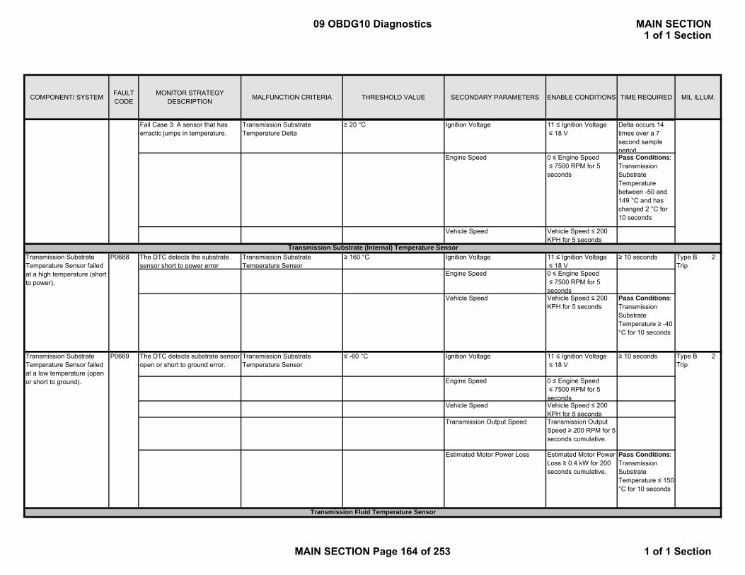
COMPONENT/ SYSTEM FAULT CODE
MONITOR STRATEGY DESCRIPTION MALFUNCTION CRITERIA THRESHOLD VALUE SECONDARY PARAMETERS ENABLE CONDITIONS TIME REQUIRED MIL ILLUM.
P M di Di iFail Case 3: A sensor that has erractic jumps in temperature.
Transmission Substrate Temperature Delta
≥ 20 °C Ignition Voltage 11 ≤ Ignition Voltage ≤ 18 V
Delta occurs 14 times over a 7 second sample period
Engine Speed 0 ≤ Engine Speed ≤ 7500 RPM for 5 seconds
Pass Conditions: Transmission Substrate Temperature between -50 and 149 °C and has changed 2 °C for 10 seconds
Vehicle Speed Vehicle Speed ≤ 200 KPH for 5 seconds
The DTC detects the substrate sensor short to power error.
Transmission Substrate Temperature Sensor
≥ 160 °C Ignition Voltage 11 ≤ Ignition Voltage≤ 18 V
≥ 10 seconds
Engine Speed 0 ≤ Engine Speed ≤ 7500 RPM for 5 seconds
Vehicle Speed Vehicle Speed ≤ 200 KPH for 5 seconds
Pass Conditions: Transmission Substrate Temperature ≥ -40 °C for 10 seconds
The DTC detects substrate sensor open or short to ground error.
Transmission Substrate Temperature Sensor
≤ -60 °C Ignition Voltage 11 ≤ Ignition Voltage ≤ 18 V
≥ 10 seconds
Engine Speed 0 ≤ Engine Speed ≤ 7500 RPM for 5 seconds
Vehicle Speed Vehicle Speed ≤ 200 KPH for 5 seconds
Transmission Output Speed Transmission Output Speed ≥ 200 RPM for 5 seconds cumulative.
Estimated Motor Power Loss Estimated Motor Power Loss ≥ 0.4 kW for 200 seconds cumulative.
Pass Conditions: Transmission Substrate Temperature ≤ 150 °C for 10 seconds
Transmission Substrate Temperature Sensor failed at a low temperature (open or short to ground).
Transmission Substrate (Internal) Temperature Sensor
P0669
Type B 2 Trip
Type B 2 Trip
Transmission Fluid Temperature Sensor
Transmission Substrate Temperature Sensor failed at a high temperature (short to power).
P0668
09 OBDG10 Diagnostics MAIN SECTION1 of 1 Section
MAIN SECTION Page 164 of 253 1 of 1 Section
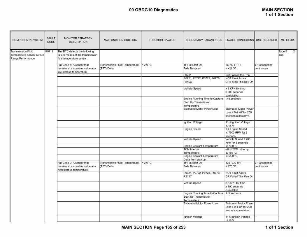
COMPONENT/ SYSTEM FAULT CODE
MONITOR STRATEGY DESCRIPTION MALFUNCTION CRITERIA THRESHOLD VALUE SECONDARY PARAMETERS ENABLE CONDITIONS TIME REQUIRED MIL ILLUM.
P M di Di iThe DTC detects the following failure modes of the transmission fluid temperature sensor:
Fail Case 1: A sensor that remains at a constant value at a low start up temperature.
Transmission Fluid Temperature (TFT) Delta
< 2.0 °C TFT at Start UpFalls Between
-50 °C ≤ TFT ≤ +21 °C
≥ 100 seconds continuous
P0711 Not Passed this TripP0721, P0722, P0723, P077B, P215C
NOT Fault Active OR Failed This Key On
Vehicle Speed ≥ 8 KPH for time ≥ 300 seconds cumulative
Engine Running Time to Capture Start Up Transmission Temperature
≥ 5 seconds
Estimated Motor Power Loss Estimated Motor Power Loss ≥ 0.4 kW for 200 seconds cumulative.
Ignition Voltage 11 ≤ Ignition Voltage≤ 18 V
Engine Speed 0 ≤ Engine Speed ≤ 7500 RPM for 5 seconds
Vehicle Speed Vehicle Speed ≤ 200 KPH for 5 seconds
Engine Coolant Temperature ≥ 70.0 °CTCM Internal Temperature
-49 ≤ TCM int temp≤ 169 °C
Engine Coolant Temperature Delta from start up
≥ 55.0 °C
Fail Case 2: A sensor that remains at a constant value at a high start up temperature.
Transmission Fluid Temperature (TFT) Delta
< 2.0 °C TFT at Start UpFalls Between
129 °C ≤ TFT ≤ 170 °C
≥ 100 seconds continuous
P0721, P0722, P0723, P077B, P215C
NOT Fault Active OR Failed This Key On
Vehicle Speed ≥ 8 KPH for time ≥ 300 seconds cumulative
Engine Running Time to Capture Start Up Transmission Temperature
≥ 5 seconds
Estimated Motor Power Loss Estimated Motor Power Loss ≥ 0.4 kW for 200 seconds cumulative.
Ignition Voltage 11 ≤ Ignition Voltage≤ 18 V
Type B 2 Trip
Transmission Fluid Temperature Sensor Circuit Range/Performance
P0711
09 OBDG10 Diagnostics MAIN SECTION1 of 1 Section
MAIN SECTION Page 165 of 253 1 of 1 Section

COMPONENT/ SYSTEM FAULT CODE
MONITOR STRATEGY DESCRIPTION MALFUNCTION CRITERIA THRESHOLD VALUE SECONDARY PARAMETERS ENABLE CONDITIONS TIME REQUIRED MIL ILLUM.
P M di Di i Engine Speed 0 ≤ Engine Speed ≤ 7500 RPM for 5 seconds
Vehicle Speed Vehicle Speed ≤ 200 KPH for 5 seconds
Engine Coolant Temperature ≥ 70.0 °CTCM Internal Temperature
-50 ≤ TCM int temp≤ 169 °C
Engine Coolant Temperature Delta from start up
≥ 55.0 °C
Fail Case 3: A sensor that has erractic jumps in temperature.
Transmission Fluid Temperature Delta
≥ 20 °C Engine Speed 0 ≤ Engine Speed ≤ 7500 RPM for 5 seconds
Delta occurs 14 times over a 7 second sample period
Vehicle Speed Vehicle Speed ≤ 200 KPH for 5 seconds
Fail Case 4: Transmission fluid temperature remains below 20° C for a calibrated time as a function of startup transmission fluid temperature.
P0721, P0722, P0723, P077B, P215C
NOTFault Active OR Failed This Key On
Fail Case 1, Fail Case 2, Fail Case 3, and Fail Case 4 independently fail.
Transmission Fluid Temperature ≤ 20 °C Engine Running Time to Capture Start Up Transmission Temperature
≥ 5 seconds A calibrated amount of time based on a 2D lookup table.
Engine Coolant Temperature, Ignition Voltage, Engine Speed
VALID Pass Conditions: Transmission Sump Temperature has changed 1.5 °C
TCM Internal Temperature
-50 ≤ TCM int temp≤ 169 °C
AND Fail Case 3 counter = 0
Vehicle Speed 8 ≤ Vehicle Speed ≤ 100 KPH
AND Transmission Operating Temperature has been met (Fail Case 4) for 10 seconds
Engine Speed 500 ≤ Engine Speed ≤ 6500 RPM
The DTC detects transmission fluid sensor short to ground error.
Transmission Substrate Temperature Sensor
≤ -60 °C P0721, P0722, P0723, P077B, P215C
NOT Fault Active OR Failed This Key On
≥ 12.75 seconds
Engine Speed 0 ≤ Engine Speed ≤ 7500 RPM for 5 seconds
Transmission Substrate Temperature Sensor failed at a low temperature (short to ground).
P0712 Type A 1 Trip
09 OBDG10 Diagnostics MAIN SECTION1 of 1 Section
MAIN SECTION Page 166 of 253 1 of 1 Section

COMPONENT/ SYSTEM FAULT CODE
MONITOR STRATEGY DESCRIPTION MALFUNCTION CRITERIA THRESHOLD VALUE SECONDARY PARAMETERS ENABLE CONDITIONS TIME REQUIRED MIL ILLUM.
P M di Di i Vehicle Speed Vehicle Speed ≤ 200 KPH for 5 seconds
Estimated Motor Power Loss Estimated Motor Power Loss ≥ 0.4 kW for 200 seconds cumulative.
Transmission Output Speed Transmission Output Speed ≥ 200 RPM for 5 seconds cumulative.
Pass Conditions: Transmission Sump Temperature ≥ -40 °C for 10 seconds
Ignition Voltage 11 ≤ Ignition Voltage≤ 18 V
The DTC detects substrate sensor open or short to ground error.
Transmission Substrate Temperature Sensor
≥ 160 °C P0721, P0722, P0723, P077B, P215C
NOT Fault Active OR Failed This Key On
≥ 25 seconds
Engine Speed 0 ≤ Engine Speed ≤ 7500 RPM for 5 seconds
Vehicle Speed Vehicle Speed ≤ 200 KPH for 5 seconds
Estimated Motor Power Loss Estimated Motor Power Loss ≥ 0.4 kW for 200 seconds cumulative.
Transmission Output Speed Transmission Output Speed ≥ 200 RPM for 5 seconds cumulative.
Pass Conditions: Transmission Substrate Temperature ≤ 149 °C for 10 seconds
Ignition Voltage 11 ≤ Ignition Voltage≤ 18 V
The DTC detects incorrect TOS direction.
TOS Raw Direction TOS Direction Raw is not Forward or Reverse
TOS Sample Period ≠ 0 ≥ 100 counts or 2.5 secondsPass Conditions: TOS Direction Raw = Forward or Reverse for 3.125 seconds (125 counts at 25ms)
Transmission Output Speed (TOS) Sensor Wrong Direction
Transmission Substrate Temperature Sensor failed at a low temperature (open or short to power).
P0721
P0713
Transmission Output Speed Sensor
Type A 1 Trip
Type A 1 Trip
09 OBDG10 Diagnostics MAIN SECTION1 of 1 Section
MAIN SECTION Page 167 of 253 1 of 1 Section

COMPONENT/ SYSTEM FAULT CODE
MONITOR STRATEGY DESCRIPTION MALFUNCTION CRITERIA THRESHOLD VALUE SECONDARY PARAMETERS ENABLE CONDITIONS TIME REQUIRED MIL ILLUM.
P M di Di iThe DTC detects no TOS sensor activity at low vehicle speed. (It compares expected output speed to an estimated output speed based on MtrA and MtrB divided by two.)
Raw Transmission Output Speed ≤ 50 RPM Motor Estimated Transmission Output Speed
150 ≤ Motor Estimated Transmission Output Speed ≤ 5200 RPM
≥ 1.5 seconds
Axle Torque 110 ≤ Axle Torque ≤ 5000 Nm
Pass Conditions: TOS ≥ 50 RPM for 1.5 seconds
The DTC detects an unrealistically large drop in TOS signal
TOS delta ≥ 1000 RPM Engine Speed 0 ≤ Engine Speed ≤ 7500 RPM for 5 seconds
≥ 6 seconds
Vehicle Speed Vehicle Speed ≤ 200 KPH for 5 seconds
Ignition Voltage 11 ≤ Ignition Voltage ≤ 18 V
Pass Conditions: TOS ≥ 500 RPM and the change in TOS is ≤ 2000 RPM for 2 seconds
The DTC detects if the Transmission Output Speed Sensor Direction is Incorrect by Comparing with Calculated Direction from Motor Speed Sign
Transmission Output Speed Direction Raw
≠ Motor Direction CAN Communication Lost With Transmission
FALSE 1.25 seconds (50 counts at 25ms)
P215C NOT Fault ActiveTOS Hardware Input Output Transmission
Valid
Hybrid Motor Speed based Estimated Output Speed is Valid
Calculated based on M1 or M2 Speed Equation
Transmission Output Speed and Motor Output Speed Difference
≤ 50 RPM Pass Conditions: Same as FAIL for 5 seconds (200 counts at 25ms)
Motor Estimated Transmission Output Speed
≥ 50 RPM
The DTC Correlates the Transmission Output Speed with the ABS Wheel Speed and Motor Speed to Detect any Failures in the Transmission Output Speed Sensor.
Difference between Transmission Output Speed and the Calculated Average of Output Speed from the Motors and Wheel Speed Sensors
≥ 140 RPM Output Speed Calculated from Motor Speeds AND Output Speed Calculated from Wheel Speeds Difference
≤ 150 RPM 200 ms (8 counts at 25ms)
Output Speed Sensor Circuit Direction Error
Type A 1 Trip
Type A 1 Trip
Type B 2 Trip
Type B 2 Trip
P077B
Transmission Output Speed (TOS) Sensor Intermittent
P0723
Transmission Output Speed (TOS) Sensor No Activity
P0722
Output Shaft Speed (OSS) - Wheel Speed Correlation
P215C
09 OBDG10 Diagnostics MAIN SECTION1 of 1 Section
MAIN SECTION Page 168 of 253 1 of 1 Section
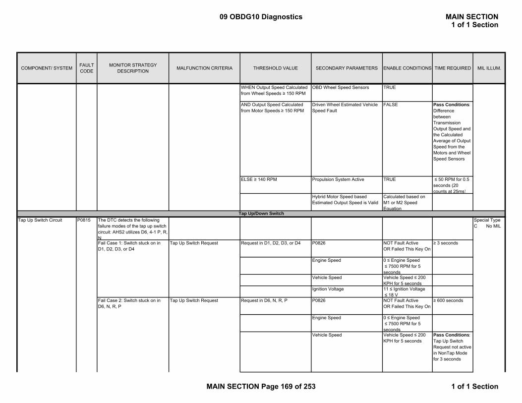
COMPONENT/ SYSTEM FAULT CODE
MONITOR STRATEGY DESCRIPTION MALFUNCTION CRITERIA THRESHOLD VALUE SECONDARY PARAMETERS ENABLE CONDITIONS TIME REQUIRED MIL ILLUM.
P M di Di iWHEN Output Speed Calculated from Wheel Speeds ≥ 150 RPM
OBD Wheel Speed Sensors TRUE
AND Output Speed Calculated from Motor Speeds ≥ 150 RPM
Driven Wheel Estimated Vehicle Speed Fault
FALSE Pass Conditions: Difference between Transmission Output Speed and the Calculated Average of Output Speed from the Motors and Wheel Speed Sensors
ELSE ≥ 140 RPM Propulsion System Active TRUE ≤ 50 RPM for 0.5 seconds (20 counts at 25ms)
Hybrid Motor Speed based Estimated Output Speed is Valid
Calculated based on M1 or M2 Speed Equation
The DTC detects the following failure modes of the tap up switch circuit: AHS2 utilizes D6, 4-1 P, R, NFail Case 1: Switch stuck on in D1, D2, D3, or D4
Tap Up Switch Request Request in D1, D2, D3, or D4 P0826 NOT Fault Active OR Failed This Key On
≥ 3 seconds
Engine Speed 0 ≤ Engine Speed ≤ 7500 RPM for 5 seconds
Vehicle Speed Vehicle Speed ≤ 200 KPH for 5 seconds
Ignition Voltage 11 ≤ Ignition Voltage≤ 18 V
Fail Case 2: Switch stuck on in D6, N, R, P
Tap Up Switch Request Request in D6, N, R, P P0826 NOT Fault Active OR Failed This Key On
≥ 600 seconds
Engine Speed 0 ≤ Engine Speed ≤ 7500 RPM for 5 seconds
Vehicle Speed Vehicle Speed ≤ 200 KPH for 5 seconds
Pass Conditions: Tap Up Switch Request not active in NonTap Mode for 3 seconds
Tap Up/Down SwitchTap Up Switch Circuit P0815 Special Type
C No MIL
09 OBDG10 Diagnostics MAIN SECTION1 of 1 Section
MAIN SECTION Page 169 of 253 1 of 1 Section

COMPONENT/ SYSTEM FAULT CODE
MONITOR STRATEGY DESCRIPTION MALFUNCTION CRITERIA THRESHOLD VALUE SECONDARY PARAMETERS ENABLE CONDITIONS TIME REQUIRED MIL ILLUM.
P M di Di i Ignition Voltage 11 ≤ Ignition Voltage≤ 18 V
The DTC detects the following failure modes of the tap down switch circuit:Fail Case 1: Switch stuck on in D1, D2, D3, or D4
Tap Down Switch Request Request in D1, D2, D3, or D4 P0826 NOT Fault Active OR Failed This Key On
≥ 3 seconds
Engine Speed 0 ≤ Engine Speed ≤ 7500 RPM for 5 seconds
Vehicle Speed Vehicle Speed ≤ 200 KPH for 5 seconds
Ignition Voltage 11 ≤ Ignition Voltage≤ 18 V
Fail Case 2: Switch stuck on in D6, N, R, P
Tap Down Switch Request Request in D6, N, R, P P0826 NOT Fault Active OR Failed This Key On
≥ 600 seconds
Engine Speed 0 ≤ Engine Speed ≤ 7500 RPM for 5 seconds
Vehicle Speed Vehicle Speed ≤ 200 KPH for 5 seconds
Pass Conditions: Tap Down Switch Request not active in NonTap Mode for 3 seconds
Ignition Voltage 11 ≤ Ignition Voltage≤ 18 V
The DTC detects the up/down shift switch circuit is at an illegal voltage.
Tap Up/Down Tap Switch Status = Illegal Switch Active (Sensor ≤ 9.5V OR Sensor ≥17.5V)
Engine Speed 0 ≤ Engine Speed ≤ 7500 RPM for 5 seconds
≥ 8 seconds
Vehicle Speed Vehicle Speed ≤ 200 KPH for 5 seconds
Pass Conditions: Enable Criteria are met for 1 second
Ignition Voltage 11 ≤ Ignition Voltage≤ 18 V
The DTC monitors the total continuous amount of tap up/down switch alive rolling count errors.
= Illegal Switch Active Engine Speed 0 ≤ Engine Speed ≤ 7500 RPM for 5 seconds
≥ 8 seconds
Vehicle Speed Vehicle Speed ≤ 200 KPH for 5 seconds
P0826
Tap Up and Down Shift Switch Signal Circuit Rolling Count
P1761
Tap Up and Down Shift Switch Circuit
Special Type C No MIL
Special Type C No MIL
Special Type C No MIL
Tap Down Switch Circuit P0816
09 OBDG10 Diagnostics MAIN SECTION1 of 1 Section
MAIN SECTION Page 170 of 253 1 of 1 Section
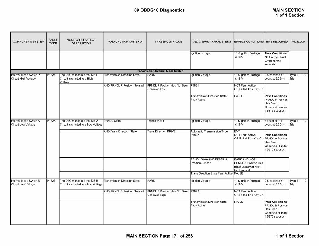
COMPONENT/ SYSTEM FAULT CODE
MONITOR STRATEGY DESCRIPTION MALFUNCTION CRITERIA THRESHOLD VALUE SECONDARY PARAMETERS ENABLE CONDITIONS TIME REQUIRED MIL ILLUM.
P M di Di i Ignition Voltage 11 ≤ Ignition Voltage ≤ 18 V
Pass Conditions: No Rolling Count Errors for 0.1 seconds
The DTC monitors if the IMS P Circuit is shorted to a High Voltage
Transmission Direction State PARK Ignition Voltage 11 ≤ Ignition Voltage ≤ 18 V
2.5 seconds + 1 count at 6.25ms
AND PRNDL P Position Sensed PRNDL P Position Has Not Been Observed Low
P1824 NOT Fault Active OR Failed This Key On
Transmission Direction State Fault Active
FALSE Pass Conditions: PRNDL P Position Has Been Observed Low for 1.5875 seconds
The DTC monitors if the IMS A Circuit is shorted to a Low Voltage
PRNDL State Transitional 1 Ignition Voltage 11 ≤ Ignition Voltage ≤ 18 V
8 seconds + 1 count at 6.25ms
AND Trans Direction State Trans Direction DRIVE Automatic Transmission Type EVTP182A NOT Fault Active
OR Failed This Key OnPass Conditions: PRNDL A Position Has Been Observed High for 1.5875 seconds
PRNDL State AND PRNDL A Position Sensed
PARK AND NOT PRNDL A Position Has Been Observed High for 1 second
Trans Direction State Fault Active FALSE
The DTC monitors if the IMS B Circuit is shorted to a Low Voltage
Transmission Direction State PARK Ignition Voltage 11 ≤ Ignition Voltage ≤ 18 V
2.5 seconds + 1 count at 6.25ms
AND PRNDL B Position Sensed PRNDL B Position Has Not Been Observed High
P182B NOT Fault Active OR Failed This Key On
Transmission Direction State Fault Active
FALSE Pass Conditions: PRNDL B Position Has Been Observed High for 1.5875 seconds
Internal Mode Switch P Circuit High Voltage
P1824
Internal Mode Switch B Circuit Low Voltage
P182B
Internal Mode Switch A Circuit Low Voltage
P182A Type B 2 Trip
Type B 2 Trip
Transmission Internal Mode Switch
Type B 2 Trip
09 OBDG10 Diagnostics MAIN SECTION1 of 1 Section
MAIN SECTION Page 171 of 253 1 of 1 Section
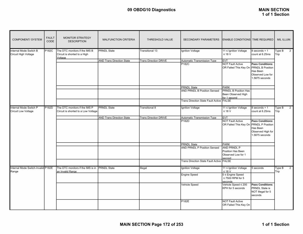
COMPONENT/ SYSTEM FAULT CODE
MONITOR STRATEGY DESCRIPTION MALFUNCTION CRITERIA THRESHOLD VALUE SECONDARY PARAMETERS ENABLE CONDITIONS TIME REQUIRED MIL ILLUM.
P M di Di iThe DTC monitors if the IMS B Circuit is shorted to a High Voltage
PRNDL State Transitional 13 Ignition Voltage 11 ≤ Ignition Voltage ≤ 18 V
8 seconds + 1 count at 6.25ms
AND Trans Direction State Trans Direction DRIVE Automatic Transmission Type EVTP182C NOT Fault Active
OR Failed This Key OnPass Conditions: PRNDL B Position Has Been Observed Low for 1.5875 seconds
PRNDL State PARKAND PRNDL B Position Sensed PRNDL B Position Has
Been Observed High for 1 second
Trans Direction State Fault Active FALSE
The DTC monitors if the IMS P Circuit is shorted to a Low Voltage
PRNDL State Transitional 8 Ignition Voltage 11 ≤ Ignition Voltage ≤ 18 V
8 seconds + 1 count at 6.25ms
AND Trans Direction State Trans Direction DRIVE Automatic Transmission Type EVTP182D NOT Fault Active
OR Failed This Key OnPass Conditions: PRNDL P Position Has Been Observed High for 1.5875 seconds
PRNDL State PARKAND PRNDL P Position Sensed AND PRNDL P
Position Has Been Observed Low for 1 second
Trans Direction State Fault Active FALSE
The DTC monitors if the IMS is in an Invalid Range
PRNDL State Illegal Ignition Voltage 11 ≤ Ignition Voltage≤ 18 V
5 seconds
Engine Speed 0 ≤ Engine Speed ≤ 7500 RPM for 5 seconds
Vehicle Speed Vehicle Speed ≤ 200 KPH for 5 seconds
Pass Conditions: PRNDL State is NOT Illegal for 5 seconds
P182E NOT Fault Active OR Failed This Key On
P182D
Internal Mode Switch B Circuit High Voltage
P182C
Internal Mode Switch P Circuit Low Voltage
Internal Mode Switch-Invalid Range
Type B 2 Trip
P182E Type B 2 Trip
Type B 2 Trip
09 OBDG10 Diagnostics MAIN SECTION1 of 1 Section
MAIN SECTION Page 172 of 253 1 of 1 Section
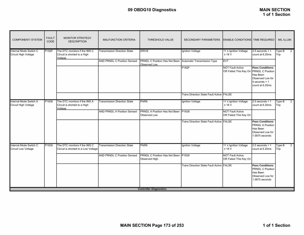
COMPONENT/ SYSTEM FAULT CODE
MONITOR STRATEGY DESCRIPTION MALFUNCTION CRITERIA THRESHOLD VALUE SECONDARY PARAMETERS ENABLE CONDITIONS TIME REQUIRED MIL ILLUM.
P M di Di iThe DTC monitors if the IMS C Circuit is shorted to a High Voltage
Transmission Direction State DRIVE Ignition Voltage 11 ≤ Ignition Voltage ≤ 18 V
2.5 seconds + 1 count at 6.25ms
AND PRNDL C Position Sensed PRNDL C Position Has Not Been Observed Low
Automatic Transmission Type EVT
P182F NOT Fault Active OR Failed This Key On
Pass Conditions: PRNDL C Position Has Been Observed Low for 4 seconds + 1 count at 6.25ms
Trans Direction State Fault Active FALSE
The DTC monitors if the IMS A Circuit is shorted to a High Voltage
Transmission Direction State PARK Ignition Voltage 11 ≤ Ignition Voltage ≤ 18 V
2.5 seconds + 1 count at 6.25ms
AND PRNDL A Position Sensed PRNDL A Position Has Not Been Observed Low
P1838 NOT Fault Active OR Failed This Key On
Trans Direction State Fault Active FALSE Pass Conditions: PRNDL A Position Has Been Observed Low for 1.5875 seconds
The DTC monitors if the IMS C Circuit is shorted to a Low Voltage
Transmission Direction State PARK Ignition Voltage 11 ≤ Ignition Voltage ≤ 18 V
2.5 seconds + 1 count at 6.25ms
AND PRNDL C Position Sensed PRNDL C Position Has Not Been Observed High
P1839 NOT Fault Active OR Failed This Key On
Trans Direction State Fault Active FALSE Pass Conditions: PRNDL C Position Has Been Observed Low for 1.5875 seconds
Controller Diagnostics
Internal Mode Switch C Circuit Low Voltage
P1839
Type B 2 Trip
Internal Mode Switch C Circuit High Voltage
P182F
Type B 2 Trip
Type B 2 Trip
Internal Mode Switch A Circuit High Voltage
P1838
09 OBDG10 Diagnostics MAIN SECTION1 of 1 Section
MAIN SECTION Page 173 of 253 1 of 1 Section
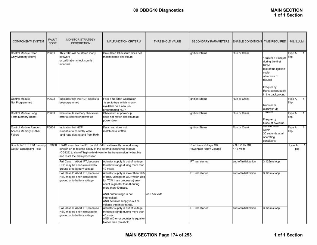
COMPONENT/ SYSTEM FAULT CODE
MONITOR STRATEGY DESCRIPTION MALFUNCTION CRITERIA THRESHOLD VALUE SECONDARY PARAMETERS ENABLE CONDITIONS TIME REQUIRED MIL ILLUM.
P M di Di iControl Module Read Only Memory (Rom)
P0601 This DTC will be stored if any software or calibration check sum is incorrect
Calculated Checksum does not match stored checksum
Ignition Status Run or Crank
1 failure if it occursduring the first ROMtest of the ignition cycle, otherwise 5 failures
Frequency:Runs continuously in the background
Type A 1 Trip
Control Module Not Programmed
P0602 Indicates that the HCP needs to be programmed
Fails if No Start Calibration is set to true which is only available on a new un-programmed HCP
Ignition Status Run or Crank
Runs once at power up
Type A 1 Trip
Control Module Long Term Memory Reset
P0603 Non-volatile memory checksum error at controller power-up
Checksum at power-up does not match checksum at power-down
Ignition Status Run or Crank 1 failure
Frequency:Once at powerup
Type A 1 Trip
Control Module Random Access Memory (RAM) Failure
P0604 Indicates that HCP is unable to correctly write and read data to and from RAM
Data read does not match data written
Ignition Status Run or Crank Should finish within 30 seconds at all operating conditions
Type A 1 Trip
Run/Crank Voltage OR Powertrain Relay Voltage
> 9.5 Volts OR < 18 Volts
Actuator supply is lower than 90% of Batt. voltage or WD(Watch Dog for TCM main processor) error count is greater than 0 during more than 40 msec.
AND output stage is not interlocked
or > 5.5 volts
AND actuator supply is out of voltage threshold range.Actuator supply is out of voltage threshold range during more than 40 msec.AND WD error counter is equal or higher than threshold.
HWIO executes the IPT (Inhibit Path Test) exactly once at every ignition on to test the ability of the external monitoring module (CG122) to shutoff high-side drivers to the transmission hydraulics and reset the main processor.
P0606Bosch T43 TEHCM Security-Output Disable/IPT Test
Type A 1 Trip
end of Initialization
end of Initialization
3.125ms loop
Fail Case 3: Abort IPT, because HSD may be short-circuited to ground or to battery voltage
IPT test started end of Initialization
Fail Case 1: Abort IPT, because HSD may be short-circuited to ground or to battery voltage
Actuator supply is out of voltage threshold range during more than 40 msec.
IPT test started
Fail Case 2: Abort IPT, because HSD may be short-circuited to ground or to battery voltage
3.125ms loop
3.125ms loopIPT test started
09 OBDG10 Diagnostics MAIN SECTION1 of 1 Section
MAIN SECTION Page 174 of 253 1 of 1 Section

COMPONENT/ SYSTEM FAULT CODE
MONITOR STRATEGY DESCRIPTION MALFUNCTION CRITERIA THRESHOLD VALUE SECONDARY PARAMETERS ENABLE CONDITIONS TIME REQUIRED MIL ILLUM.
P M di Di iAND output stage is interlocked - WD error counter: >=5
AND Actuator supply is lower than 90% of Batt. Voltage.
Fail Case 4: WD error counter does not reach its desired level (sdi Ufet = 1)
WD error count is higher than threshold
- WD error count: 0 IPT test started end of Initialization 3.125ms loop
Fail Case 5: WD error counter does not reach its desired level (sdi Ufet = 4)
WD error count is equal or higher than threshold
- WD error count: 4 IPT test started end of Initialization 3.125ms loop
Fail Case 6: WD error counter does not reach its desired level (sdi Ufet = 6)
WD error count is higher than threshold
- WD error count: 0 IPT test completed end of Initialization 3.125ms loop
Actuator supply is lower than 90% of Batt. Voltage or WD error count is higher than threshold during more than 40 msec.
- WD error counter: > 0
AND output stage is not interlocked
AND actuator supply voltage is within range
- actuator supply voltage: >1.5 voltsand <= 5.5 volts
Fail Case 8:DReset line = low level, HSD cannot be switched on
Actuator supply is lower than 90% of Batt. Voltage or WD error count is higher than 0 during more than 40 msec.
(fgtr_DReset = True) AND output stage is interlocked.
Fail Case 9:HSD cannot be switched off at
Actuator supply voltage is out of range or WD error count is lower than threshold during more than 40 msec.
- actuator supply voltage: < 1.5 volts or > 5.5 volts
WD error counter >= 5 AND output stage is interlocked
AND actuator supply voltage is equal or higher than 90% of the Batt. Voltage.
-WD error counter:<5
Fail Case 10: DReset line = high level, HSD cannot be switched off
Actuator supply voltage is out of threshold range during more than 40 msec.
- actuator supply voltage: < 1.5 volts or > 5.5 volts
(fgtr_DReset = False) AND WD error count is equal or higher than thresholdAND output stage is not interlocked
- WD error count:>= 5
Fail Case 11: Run time of IPT function too long
IPT execution time is equal or greater than time threshold.
- time threshold : 300ms IPT test started end of Initialization 3.125ms loop
≥ 5 volts 1 failure
Frequency:
3.125ms loop
3.125ms loop
Type A 1 Trip
Fail Case 7:HSD(High Side Driver) cannot be switched on at WD error counter <= 4
IPT test started end of Initialization 3.125ms loop
IPT test started end of Initialization
IPT test started
IPT test started end of Initialization 3.125ms loop
end of Initialization
Ignition voltageControl Module Long Term Memory Performance
P062F Indicates that the NVM Error flag has not been cleared
Last EEPROM write did not complete
09 OBDG10 Diagnostics MAIN SECTION1 of 1 Section
MAIN SECTION Page 175 of 253 1 of 1 Section

COMPONENT/ SYSTEM FAULT CODE
MONITOR STRATEGY DESCRIPTION MALFUNCTION CRITERIA THRESHOLD VALUE SECONDARY PARAMETERS ENABLE CONDITIONS TIME REQUIRED MIL ILLUM.
P M di Di i Once at power-up
Fail Case 1: AtoD converter test result is failed
0 x Vref is higher than voltage threshold
> approx. 0.01467 Volts 6.25ms
< approx. 2.479 Voltsor > approx. 2.518 Volts< approx. 4.978 Voltsor > approx. 5 Volts
10 fail counts out of 16 sample countsExecutes in a 12.5ms loopDetects in 200ms
Transmission is 4th gear position. - PCS2 Command > 1800kpa
AND Range State is 7 - PCS3 Command > 1800kpaAND X Valve Command has been corrupted to 0
-PCS4 Command < 100kpa
AND Y Valve Command is 1 -time threshold: 200msecAND PCS2 Command is higher than thresholdAND PCS3 Command higher than thresholdAND PCS4 Command lower than threshold during more than time threshold
Detects in 200ms
Transmission is 4th Gear position - PCS2 Command > 1800kpa
AND Range State is 7 - PCS3 Command > 1800kpaAND X Valve Command is 1 - PCS4 Command < 100kpaAND Y Valve Command has been corrupted to 0
-time threshold: 200msec
AND PCS2 Command is higher than thresholdAND PCS3 Command higher than thresholdAND PCS4 Command lower than threshold during more than time threshold
Detects in 200ms
Transmission is 3rd Gear position - PCS2 Command > 1800kpa
AND Range State is 5 - PCS4 Command :< 100kpaAND X Valve Command is 1 -time threshold: 200msecAND Y Valve Command is 0
0.5 x Vref is out of voltage threshold
HWIO executes the A/D converter test. This test checks the Vref voltage at 3 levels.
Detects controller faults such that solenoid commands doesn't match with it's expected associated Range State value.
Fail Case 2: AtoD converter test result is failed
P16F3 Detect the dual store memory fault by comparing the primary value and the dual store value of the Hybrid Range State
Dual store value of the Hybrid Range State is not equal to primary dual store value.
Internal Control Module A/D Processing Performance
P060B
1.0 x Vref is out of voltage threshold.
Type A 1 Trip
in crank or run Type A 1 Trip
Run/Crank Voltage OR Powertrain Relay Voltage
> 9.5 Volts OR < 18 Volts
Torque Security Faults
Fail Case 3: AtoD converter test result is failed
Ignition switch in crank or run
Fail Case 2
6.25ms
6.25ms
Ignition switch in crank or run Executes in a 12.5ms loop
Ignition switch
Executes in a 12.5ms loop
Executes in a 12.5ms loop
Ignition switch in crank or run
Type A 1 Trip
Clutch pressure combination / valve commands do not fit to allowed range state
P16F7Fail Case 1
Dual Store Fault
Fail Case 3
09 OBDG10 Diagnostics MAIN SECTION1 of 1 Section
MAIN SECTION Page 176 of 253 1 of 1 Section
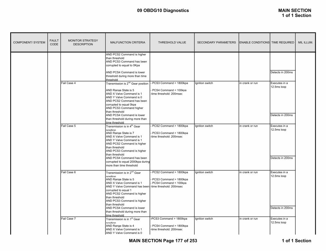
COMPONENT/ SYSTEM FAULT CODE
MONITOR STRATEGY DESCRIPTION MALFUNCTION CRITERIA THRESHOLD VALUE SECONDARY PARAMETERS ENABLE CONDITIONS TIME REQUIRED MIL ILLUM.
P M di Di iAND PCS2 Command is higher than thresholdAND PCS3 Command has been corrupted to equal to 0Kpa
AND PCS4 Command is lower threshold during more than time threshold
Detects in 200ms
Transmission is 2nd Gear position - PCS3 Command > 1800kpa
AND Range State is 5 - PCS4 Command < 100kpaAND X Valve Command is 1 -time threshold: 200msecAND Y Valve Command is 0AND PCS2 Command has been corrupted to equal 0kpaAND PCS3 Command higher than thresholdAND PCS4 Command is lower than threshold during more than time threshold
Detects in 200ms
Transmission is in 4th Gear position
- PCS2 Command > 1800kpa
AND Range State is 7 - PCS3 Command > 1800kpaAND X Valve Command is 1 -time threshold: 200msecAND Y Valve Command is 1AND PCS2 Command is higher than threshold AND PCS3 Command is higher than thresholdAND PCS4 Command has been corrupted to equal 2000kpa during more than time threshold
Detects in 200ms
Transmission is in 2nd Gear position
- PCS2 Command > 1800kpa
AND Range State is 5 - PCS3 Command > 1800kpaAND X Valve Command is 1 - PCS4 Command < 100kpaAND Y Valve Command has been corrupted to equal 1
-time threshold: 200msec
AND PCS2 Command is higher than threshold AND PCS3 Command is higher than thresholdAND PCS4 Command is lower than threshold during more than time threshold
Detects in 200ms
Transmission is in 1st Gear position
-PCS3 Command > 1800kpa
AND Range State is 4 - PCS4 Command > 1800kpaAND X Valve Command is 1 -time threshold: 200msecAND Y Valve Command is 0
Ignition switch in crank or run Executes in a 12.5ms loop
Ignition switch in crank or run Executes in a 12.5ms loop
Ignition switch
Executes in a 12.5ms loop
in crank or run
Fail Case 7 Ignition switch in crank or run
Executes in a 12.5ms loop
Fail Case 6
Fail Case 5
Fail Case 4
09 OBDG10 Diagnostics MAIN SECTION1 of 1 Section
MAIN SECTION Page 177 of 253 1 of 1 Section
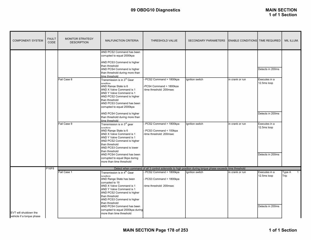
COMPONENT/ SYSTEM FAULT CODE
MONITOR STRATEGY DESCRIPTION MALFUNCTION CRITERIA THRESHOLD VALUE SECONDARY PARAMETERS ENABLE CONDITIONS TIME REQUIRED MIL ILLUM.
P M di Di iAND PCS2 Command has been corrupted to equal 2000kpa
AND PCS3 Command is higher than thresholdAND PCS4 Command is higher than threshold during more than time threshold
Detects in 200ms
Transmission is in 3rd Gear position
- PCS2 Command > 1800kpa
AND Range State is 6 -PCS4 Command > 1800kpaAND X Valve Command is 1 -time threshold: 200msecAND Y Valve Command is 1AND PCS2 Command is higher than thresholdAND PCS3 Command has been corrupted to equal 2000kpa
AND PCS4 Command is higher than threshold during more than time threshold
Detects in 200ms
Transmission is in 3rd gear position
- PCS2 Command > 1800kpa
AND Range State is 6 - PCS3 Command < 100kpaAND X Valve Command is 1 -time threshold: 200msecAND Y Valve Command is 1AND PCS2 Command is higher than thresholdAND PCS3 Command is lower than thresholdAND PCS4 Command has been corrupted to equal 0kpa during more than time threshold
Detects in 200ms
Transmission is in 4th Gear position
- PCS2 Command > 1800kpa
AND Range State has been corrupted to 19
- PCS3 Command > 1800kpa
AND X Valve Command is 1 -time threshold: 200msecAND Y Valve Command is 1AND PCS2 Command is higher than threshold AND PCS3 Command is higher than thresholdAND PCS4 Command has been corrupted to equal 2000kpa during more than time threshold
Detects in 200ms
Detect when command of all 3 control solenoids to high position during torque phase exceeds time threshold
in crank or run
Fail Case 8 Ignition switch in crank or run
Fail Case 9 Ignition switch
Executes in a 12.5ms loop
Executes in a 12.5ms loop
Type A 1 Trip
Executes in a 12.5ms loop
EVT will shutdown the vehicle if a torque phase
P16F8Fail Case 1 Ignition switch in crank or run
09 OBDG10 Diagnostics MAIN SECTION1 of 1 Section
MAIN SECTION Page 178 of 253 1 of 1 Section

COMPONENT/ SYSTEM FAULT CODE
MONITOR STRATEGY DESCRIPTION MALFUNCTION CRITERIA THRESHOLD VALUE SECONDARY PARAMETERS ENABLE CONDITIONS TIME REQUIRED MIL ILLUM.
P M di Di iTransmission is in 2nd Gear position
- PCS2 Command > 1800kpa
AND Range State has been corrupted to 11
- PCS3 Command > 1800kpa
AND X Valve Command is 1 -time threshold: 200msecAND Y Valve Command is 0AND PCS2 Command is higher than thresholdAND PCS3 Command is higher than thresholdAND PCS4 Command has been corrupted to equal 2000kpa during more than time threshold
Detects in 200ms
10 fail counts out of 16 sample countsExecutes in a 12.5ms loopDetects in 200ms
Control Module Communication Bus A Off
U0073 Detects that a CAN serial data bus shorted condition has occurred to force the CAN device driver to enter a bus-off state.
CAN device driver = bus-off state. Run/Crank Voltage OR Powertrain Relay Voltage
> 9.5 Volts OR < 18 Volts
3 failures out of 5 samples
Detects in 450 msec at loop rate
of 12.5 msec
Type A
Lost Communication With ECM/PCM on Bus A
U0100 Detects that CAN serial data communication has been lost with the ECM on Bus A
Missed ECM Messages Run/Crank Voltage OR Powertrain Relay Voltage
> 9.5 Volts OR < 18 Volts
Detects within 500 msec at 6.25 msec
loop rate
Type A
Lost Communication With Hybrid Controller
U0293 Detects that CAN serial data communication has been lost with the HCP
Missed HCP Messages Run/Crank Voltage OR Powertrain Relay Voltage
> 9.5 Volts OR < 18 Volts
Detects within 500 msec at 6.25 msec
loop rate
Type A
P0711: Reference TableStart Up Transmission
Temperature °CTime for Transmission
Temperature to Reach 20 °C
-50 3200-25 2600-10 2000-5 180020 300
Communication
Ignition switch in crank or runfault occurs
Alive Rolling Count / Protection Value fault
P179B Detect the ARC (Alive Rolling Count) or Protection Value fault by checking the ARC and Protection Value of the Hybrid Range State
Current ARC is not equal to previous ARC + 1 and Primary Value is not equal to protection value
Type A 1 Trip
Executes in a 12.5ms loop
Run/Crank Voltage OR Powertrain Relay Voltage
> 9.5 Volts OR < 18 Volts
Fail Case 2
09 OBDG10 Diagnostics MAIN SECTION1 of 1 Section
MAIN SECTION Page 179 of 253 1 of 1 Section

COMPONENT/ SYSTEM FAULT CODE
MONITOR STRATEGY DESCRIPTION MALFUNCTION CRITERIA THRESHOLD VALUE SECONDARY PARAMETERS ENABLE CONDITIONS TIME REQUIRED MIL ILLUM.
Fuel Rail Pressure (FRP) Sensor Performance (Rationality)
P0191 This DTC detects if the fuel pressure sensor is stuck within the normal operating range
Absolute value of change in fuel pressure as sensed during intrusive test.
<= 30 kPa
1. FRP Circuit Low DTC (P0192) not active
Frequency:Continuous; 12.5 ms loop. 60 seconds between intrusive tests that pass
Intrusive test requested if fuel system is clamped for >= 5 seconds or fuel pressure error variance <= 0.6 (calculated over a 2.5sec period); otherwise report pass
Type A1 trip
2. FRP Circuit High DTC (P0193) not active 3. FuelPump Circuit Low DTC (P0231)
not active
Duration of intrusive test is fueling related (5 to 12 seconds).
4. FuelPump Circuit High DTC (P0232)
not active
5. FuelPump Circuit Open DTC (P023F)
not active Intrusive test is run when fuel flow is < 29.7 g/s
6. Reference Voltage DTC (P0641)
not active
7. Reference Voltage DTC (P06A6)
not active
8. Fuel Pump Control Module Driver Over-temperature DTC’s (P064A, P1255)
not active
9. Control Module Internal Performance DTC (P0606)
not active
10. Engine run time >=5 seconds11. Emissions fuel level (PPEI $3FB)
not low
12. Fuel pump control enabled 13. Fuel pump control state normal or FRP
Rationality control 14. Engine fuel flow > 0.047 g/s15. ECM fuel control system failure (PPEI $1ED)
failure has not occurred
Fuel System Control Module (FSCM):
09 OBDG10 Diagnostics MAIN SECTION1 of 1 Section
MAIN SECTION Page 180 of 253 1 of 1 Section

COMPONENT/ SYSTEM FAULT CODE
MONITOR STRATEGY DESCRIPTION MALFUNCTION CRITERIA THRESHOLD VALUE SECONDARY PARAMETERS ENABLE CONDITIONS TIME REQUIRED MIL ILLUM.
F l S C l M d l (FSCM)Fuel Rail Pressure (FRP) Sensor Circuit Low Voltage
P0192 This DTC detects if the fuel pressure sensor circuit is shorted to low
FRP sensor voltage < 0.1 V
Ignition Run or Crank
72 failures out of 80 samples
1 sample/12.5 ms
Type A1 trip
Fuel Rail Pressure (FRP) Sensor Circuit High Voltage
P0193 This DTC detects if the fuel pressure sensor circuit is shorted to high
FRP sensor voltage > 4.9 V
Ignition Run or Crank
72 failures out of 80 samples
1 sample/12.5 ms
Type A1 trip
Fuel Pump Control Circuit Low Voltage
P0231 This DTC detects if the fuel pump control circuit is shorted to low
Fuel Pump Current > 14.48A
Ignition Run or Crank
72 test failures in 80 test samples if Fuel Pump Current <100A
Type A1 trip
OR 3 test failures in 15 test samples if Fuel Pump Current >=100A
HS Comm enabledOR 1 sample/12.5 msFuel Pump Control enabledAND Ignition Run/Crank Voltage 9V < voltage < 18V
Fuel Pump Control Circuit High Voltage
P0232 This DTC detects if the fuel pump control circuit is shorted to high
Voltage measured at fuel pump circuit
> 3.86 V Commanded fuel pump output 0% duty cycle (off) 36 test failures in 40 test samples; 1 sample/12.5ms
Type A1 trip
Fuel pump control enable False Pass/Fail determination made only once per trip
Time that above conditions are met
>=4.0 seconds
Fuel Pump Control Circuit (Open)
P023F This DTC detects if the fuel pump control circuit is open
Fuel Pump Current <=0.5A
�Ignition Run or Crank
72 test failures in 80 test samples; 1 sample/12.5ms
Type A1 trip
AND OR Fuel Pump Duty Cycle >20% HS Comm enabled
OR Fuel Pump Control enabledAND Ignition Run/Crank Voltage 9V < voltage < 18V
09 OBDG10 Diagnostics MAIN SECTION1 of 1 Section
MAIN SECTION Page 181 of 253 1 of 1 Section

COMPONENT/ SYSTEM FAULT CODE
MONITOR STRATEGY DESCRIPTION MALFUNCTION CRITERIA THRESHOLD VALUE SECONDARY PARAMETERS ENABLE CONDITIONS TIME REQUIRED MIL ILLUM.
F l S C l M d l (FSCM)Fuel System Control Module Enable Control Circuit
P025A This DTC detects if there is a fault in the fuel pump control enable circuit
PPEI (PPEI (Powertrain Platform Electrical Interface) Fuel System Request ($1ED)
≠ Fuel Pump Control Module Enable Control Circuit
Ignition Run or Crank
72 failures out of 80 samples
1 sample/12.5 ms
Type A1 trip
AND PPEI Fuel System Request ($1ED)
valid
Control Module Read Only Memory (ROM)
P0601 This DTC will be stored if any software or calibration check sum is incorrect
Calculated Checksum (CRC16) ≠ stored checksum for any of the parts (boot, software, application calibration, system calibration)
Ignition Run or Crank
1 failure if it occurs during the first ROM test of the ignition cycle, otherwise 5 failures
Type A1 trip
OR Frequency:Runs continuously in the background
HS Comm enabledOR Fuel Pump Control enabled
Control Module Not Programmed
P0602 Indicates that the FSCM needs to be programmed
This DTC is set via calibration, when KeMEMD_b_NoStart Cal
TRUE
Ignition Run or Crank
Runs once at power up
Type A1 trip
OR HS Comm enabledOR Fuel Pump Control enabled
Control Module Long Term Memory Reset
P0603 Non-volatile memory checksum error at controller power-up
Checksum at power-up ≠ checksum at power-down
Ignition Run or Crank
1 failure
Frequency:Once at power-up
DTC Type A1 trip
OR HS Comm enabledOR Fuel Pump Control enabled
Control Module Random Access Memory (RAM)
P0604 Indicates that control module is unable to correctly write and read data to and from RAM
Data read ≠ Data written
Ignition Run or Crank
1 failure if it occurs during the first RAM test of the ignition cycle, otherwise 5 failures
Type A1 trip
OR Frequency:
09 OBDG10 Diagnostics MAIN SECTION1 of 1 Section
MAIN SECTION Page 182 of 253 1 of 1 Section

COMPONENT/ SYSTEM FAULT CODE
MONITOR STRATEGY DESCRIPTION MALFUNCTION CRITERIA THRESHOLD VALUE SECONDARY PARAMETERS ENABLE CONDITIONS TIME REQUIRED MIL ILLUM.
F l S C l M d l (FSCM) HS Comm enabled Runs continuously in the background.
OR Fuel Pump Control enabled
Control Module Internal Performance 1. Main Processor Configuration Register Test
P0606
1. For all I/O configuration register faults:
•Register contents Incorrect value. Ignition Run or Crank
Tests 1 and 2 1 failureFrequency:Continuously (12.5ms)
Type A1 trip
OR HS Comm enabledOR Fuel Pump Control enabled
2. Processor clock test
2. For Processor Clock Fault: •EE latch flag in EEPROM. OR
0x5A5A
1. For all I/O configuration register faults: •KeMEMD_b_ProcFltCfgRegEnbl TRUE
Test 33 failures out of 15 samples
1 sample/12.5 ms• RAM latch flag. 0x5A 2. For Processor Clock Fault:
•KeMEMD_b_ProcFltCLKDiagEnbl
TRUE
3. External watchdog test 3. For External Watchdog Fault:• Software control of viper chip.
Control Lost
3. For External Watchdog Fault:•KeFRPD_b_FPExtWDogDiagEnbl
TRUE3. For External Watchdog Fault:•Control Module ROM(P0601)
not active3. For External Watchdog Fault:•Control Module RAM(P0604)
not activeControl Module Long Term Memory (EEPROM) Performance
P062F Indicates that the NVM Error flag has not been cleared
Last EEPROM write Did not complete
Ignition Run or Crank
1 test failureOnce on controller power-up
Type A1 trip
OR HS Comm enabledOR Fuel Pump Control enabled
5 Volt Reference Circuit (Short High/Low)
P0641 Detects a continuous short on the #1 5V sensor reference circuit
Reference voltage AND >= 0.5V . Ignition Run or Crank
15 failures out of 20 samples
1 sample/12.5 ms
Type A1 trip
This DTC indicates the FSCM has detected an internal processor fault or external watchdog fault (PID 2032 can tell what causes the fault.)
09 OBDG10 Diagnostics MAIN SECTION1 of 1 Section
MAIN SECTION Page 183 of 253 1 of 1 Section

COMPONENT/ SYSTEM FAULT CODE
MONITOR STRATEGY DESCRIPTION MALFUNCTION CRITERIA THRESHOLD VALUE SECONDARY PARAMETERS ENABLE CONDITIONS TIME REQUIRED MIL ILLUM.
F l S C l M d l (FSCM) Output OR
inactive
Reference voltage AND >= 5.5VOutput OR activeReference voltage AND <= 4.5VOutput active
5 Volt Reference Circuit (Out of Range)
P06A6 Detects that the #1 5 V sensor reference circuit is out of range
Reference voltage �
> 102.5% nominal (i.e. 5.125V)
Ignition Run or Crank
72 failures out of 80 samples
Type A1 trip
OR 1 sample/12.5 ms< 97.5% nominal (i.e. 4.875V)
Fuel Pump Control Module - Driver Over-temperature 2
P1255 This DTC detects if an internal fuel pump driver overtemperature condition exists under extreme operating conditions (GM’s responsibility )
Module Range of Operation Outside normal range ( FSCM is NOT in normal operating range for module voltage versus PWM duty cycle. Linear range from 100% @ 12.5V to 70% @ 18V.)
Ignition Run or Crank
3 failures out of 15 samples
1 sample/12.5 ms
Type B2 trips
OR AND HS Comm enabled
OR Fuel Pump Control enabled
Viper Temp > 190C
KeFRPD_b_FPOverTempDiagEnbl TRUEIgnition Run/Crank 9V<voltage<18V
Ignition 1 Switch Circuit Low Voltage
P2534 This DTC detects if the Ignition1 Switch circuit is shorted to low or open
Ignition 1 voltage <= 6 V Engine Running 144 failures out of 160 samples
1 sample/12.5 ms
Type A1 trip
Fuel Pump Flow Performance
P2635 This DTC detects degradation in the performance of the electronic return-less fuel system
Filtered fuel rail pressure error <= Low Threshold ( function of desired fuel rail pressure and fuel flow rate. Typical values in the range of -28.4 to -193.5 kPa.) . OR
1. FRP Circuit Low DTC (P0192) not active
Filtered fuel rail pressure error Time Constant = 12.5 seconds
Frequency:Continuous100 ms loop
Type B2 trips
2. FRP Circuit High DTC (P0193) not active . . . .
> High Threshold ( function of desired fuel rail pressure and fuel flow rate. Typical values in the range of 19.5 to 166.5 kPa.)
09 OBDG10 Diagnostics MAIN SECTION1 of 1 Section
MAIN SECTION Page 184 of 253 1 of 1 Section
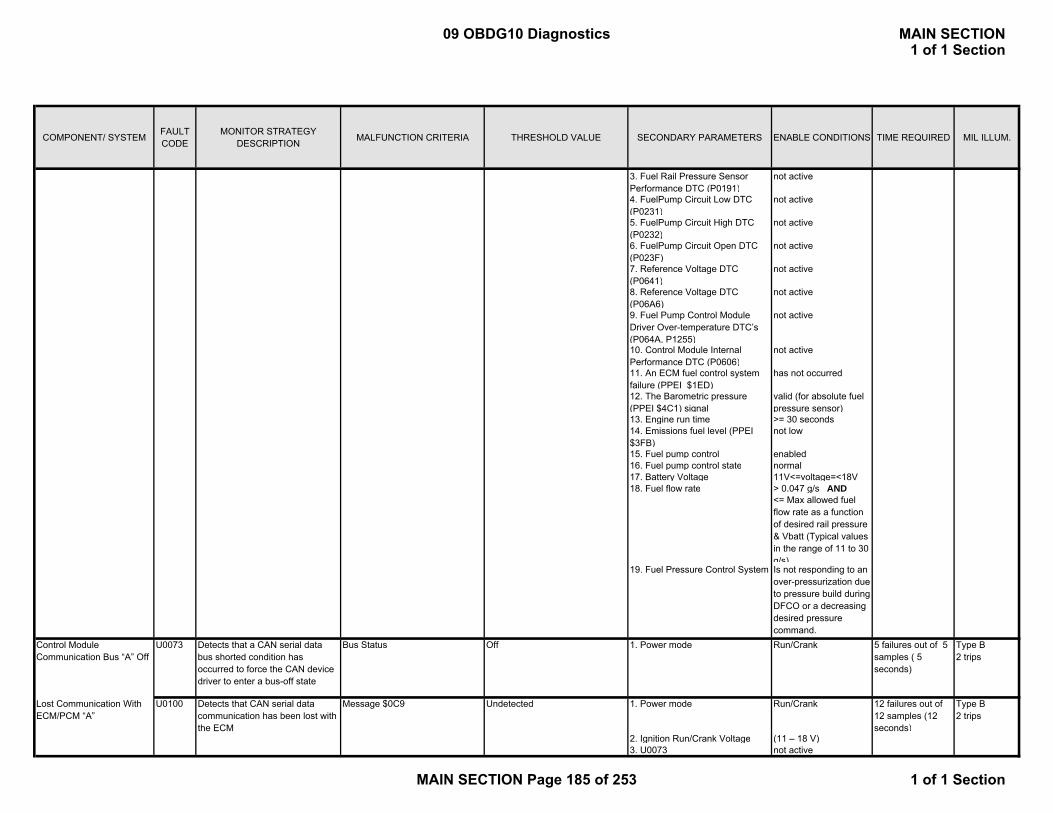
COMPONENT/ SYSTEM FAULT CODE
MONITOR STRATEGY DESCRIPTION MALFUNCTION CRITERIA THRESHOLD VALUE SECONDARY PARAMETERS ENABLE CONDITIONS TIME REQUIRED MIL ILLUM.
F l S C l M d l (FSCM) 3. Fuel Rail Pressure Sensor Performance DTC (P0191)
not active
4. FuelPump Circuit Low DTC (P0231)
not active
5. FuelPump Circuit High DTC (P0232)
not active
6. FuelPump Circuit Open DTC (P023F)
not active
7. Reference Voltage DTC (P0641)
not active
8. Reference Voltage DTC (P06A6)
not active
9. Fuel Pump Control Module Driver Over-temperature DTC’s (P064A, P1255)
not active
10. Control Module Internal Performance DTC (P0606)
not active
11. An ECM fuel control system failure (PPEI $1ED)
has not occurred
12. The Barometric pressure (PPEI $4C1) signal
valid (for absolute fuel pressure sensor)
13. Engine run time >= 30 seconds 14. Emissions fuel level (PPEI $3FB)
not low
15. Fuel pump control enabled 16. Fuel pump control state normal 17. Battery Voltage 11V<=voltage=<18V 18. Fuel flow rate > 0.047 g/s AND
<= Max allowed fuel flow rate as a function of desired rail pressure & Vbatt (Typical values in the range of 11 to 30 g/s)
19. Fuel Pressure Control System Is not responding to an over-pressurization due to pressure build during DFCO or a decreasing desired pressure command.
Control Module Communication Bus “A” Off
U0073 Detects that a CAN serial data bus shorted condition has occurred to force the CAN device driver to enter a bus-off state
Bus Status Off 1. Power mode Run/Crank 5 failures out of 5 samples ( 5 seconds)
Type B2 trips
Lost Communication With ECM/PCM “A”
U0100 Detects that CAN serial data communication has been lost with the ECM
Message $0C9 Undetected 1. Power mode Run/Crank 12 failures out of 12 samples (12 seconds)
Type B2 trips
2. Ignition Run/Crank Voltage (11 – 18 V)3. U0073 not active
09 OBDG10 Diagnostics MAIN SECTION1 of 1 Section
MAIN SECTION Page 185 of 253 1 of 1 Section
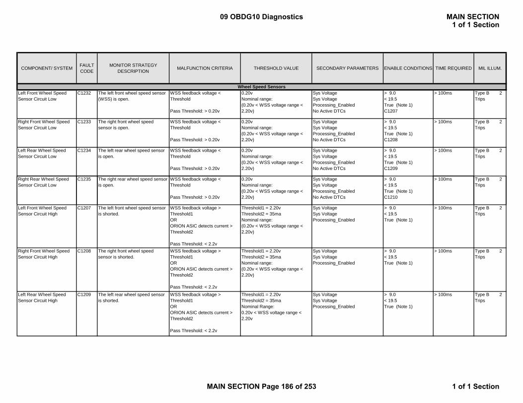
COMPONENT/ SYSTEM FAULT CODE
MONITOR STRATEGY DESCRIPTION MALFUNCTION CRITERIA THRESHOLD VALUE SECONDARY PARAMETERS ENABLE CONDITIONS TIME REQUIRED MIL ILLUM.
Left Front Wheel Speed Sensor Circuit Low
C1232 The left front wheel speed sensor (WSS) is open.
WSS feedback voltage < Threshold
Pass Threshold: > 0.20v
0.20vNominal range:(0.20v < WSS voltage range < 2.20v)
Sys VoltageSys VoltageProcessing_EnabledNo Active DTCs
> 9.0< 19.5True (Note 1)C1207
> 100ms Type B 2 Trips
Right Front Wheel Speed Sensor Circuit Low
C1233 The right front wheel speed sensor is open.
WSS feedback voltage < Threshold
Pass Threshold: > 0.20v
0.20vNominal range:(0.20v < WSS voltage range < 2.20v)
Sys VoltageSys VoltageProcessing_EnabledNo Active DTCs
> 9.0< 19.5True (Note 1)C1208
> 100ms Type B 2 Trips
Left Rear Wheel Speed Sensor Circuit Low
C1234 The left rear wheel speed sensor is open.
WSS feedback voltage < Threshold
Pass Threshold: > 0.20v
0.20vNominal range:(0.20v < WSS voltage range < 2.20v)
Sys VoltageSys VoltageProcessing_EnabledNo Active DTCs
> 9.0< 19.5True (Note 1)C1209
> 100ms Type B 2 Trips
Right Rear Wheel Speed Sensor Circuit Low
C1235 The right rear wheel speed sensor is open.
WSS feedback voltage < Threshold
0.20vNominal range:
Sys VoltageSys Voltage
> 9.0< 19.5
> 100ms Type B 2 Trips
Wheel Speed Sensors
Pass Threshold: > 0.20v(0.20v < WSS voltage range < 2.20v)
Processing_EnabledNo Active DTCs
True (Note 1)C1210
Left Front Wheel Speed Sensor Circuit High
C1207 The left front wheel speed sensor is shorted.
WSS feedback voltage > Threshold1ORORION ASIC detects current > Threshold2
Pass Threshold: < 2.2v
Threshold1 = 2.20vThreshold2 = 35maNominal range:(0.20v < WSS voltage range < 2.20v)
Sys VoltageSys VoltageProcessing_Enabled
> 9.0< 19.5True (Note 1)
> 100ms Type B 2 Trips
Right Front Wheel Speed Sensor Circuit High
C1208 The right front wheel speed sensor is shorted.
WSS feedback voltage > Threshold1ORORION ASIC detects current > Threshold2
Pass Threshold: < 2.2v
Threshold1 = 2.20vThreshold2 = 35maNominal range:(0.20v < WSS voltage range < 2.20v)
Sys VoltageSys VoltageProcessing_Enabled
> 9.0< 19.5True (Note 1)
> 100ms Type B 2 Trips
Left Rear Wheel Speed Sensor Circuit High
C1209 The left rear wheel speed sensor is shorted.
WSS feedback voltage > Threshold1ORORION ASIC detects current > Threshold2
Pass Threshold: < 2.2v
Threshold1 = 2.20vThreshold2 = 35maNominal Range:0.20v < WSS voltage range < 2.20v
Sys VoltageSys VoltageProcessing_Enabled
> 9.0< 19.5True (Note 1)
> 100ms Type B 2 Trips
09 OBDG10 Diagnostics MAIN SECTION1 of 1 Section
MAIN SECTION Page 186 of 253 1 of 1 Section

COMPONENT/ SYSTEM FAULT CODE
MONITOR STRATEGY DESCRIPTION MALFUNCTION CRITERIA THRESHOLD VALUE SECONDARY PARAMETERS ENABLE CONDITIONS TIME REQUIRED MIL ILLUM.
Right Rear Wheel Speed Sensor Circuit High
C1210 The right rear wheel speed sensor is shorted.
WSS feedback voltage > Threshold1ORORION ASIC detects current > Threshold2
Pass Threshold: < 2.2v
Threshold1 = 2.20vThreshold2 = 35maNominal range:(0.20v < WSS voltage range < 2.20v)
Sys VoltageSys VoltageProcessing_Enabled
> 9.0< 19.5True (Note 1)
> 100ms Type B 2 Trips
The left front WSS signal has dropped out. It has stopped producing edges.
Number of detected edges = 0 0 edgesNominal Range:(N/A)
Veh VelSystem VoltageProcessing_EnabledNo Active DTCs
> 12.8kph< 19.5True (Note 1)C1207
20ms Type B 2 Trips
Missing signal. The left front wheel speed sensor is no longer being detected.
For Single Missing, TC Active, and Multiple Missing WSS’s: Missing Threshold = Larger of: (0.2 x Max)m/s or 1.8m/s Max is the maximum filtered velocity from the other 3 wheels
See Malfunction CriteriaNominal Range:(0.6kph < WSS vel range < 240kph)
Accel (on all wheels)
Veh Vel (largest from all 4 wheels)Processing_EnabledNo Active DTCs
< 17.16m/s/s
> 12.8kphTrue (Note 1)C1207
Single: Time > 5sSingle TC Active: Time > 60sMultiple:
Time > 2minutes
Type B 2 Trips
C1221Left Front Wheel Speed Sensor Circuit
velocity from the other 3 wheels
Pass Threshold: WSS signal is detected
No Active DTCs Time > 2minutes/ > 15 ms
The right front WSS signal has dropped out. It has stopped producing edges.
Number of detected edges = 0 0 edgesNominal Range:(N/A)
Veh VelSystem VoltageProcessing_EnabledNo Active DTCs
> 12.8kph< 19.5True (Note 1)C1208
20ms Type B 2 Trips
Missing signal. The right front wheel speed sensor is no longer being detected.
For Single Missing, TC Active, and Multiple Missing WSS’s: Missing Threshold = Larger of: (0.2 x Max)m/s or 1.8m/s Max is the maximum filtered velocity from the other 3 wheels
Pass Threshold: WSS signal is detected
See Malfunction CriteriaNominal Range:(0.6kph < WSS vel range < 240kph)
Accel (on all wheels)
Veh Vel (largest from all 4 wheels)Processing_EnabledNo Active DTCs
< 17.16m/s/s
> 12.8kphTrue (Note 1)C1208
Single: Time > 5sSingle TC Active: Time > 60sMultiple: Time > 2minutes/ > 15 ms
Type B 2 Trips
The left rear WSS signal has dropped out. It has stopped producing edges.
Number of detected edges = 0 0 edgesNominal Range:(N/A)
Veh VelSystem VoltageProcessing_EnabledNo Active DTCs
> 12.8kph< 19.5True (Note 1)C1209
20ms Type B 2 Trips
Right Front Wheel Speed Sensor Circuit
C1222
Left Rear Wheel Speed Sensor Circuit
C1223
09 OBDG10 Diagnostics MAIN SECTION1 of 1 Section
MAIN SECTION Page 187 of 253 1 of 1 Section

COMPONENT/ SYSTEM FAULT CODE
MONITOR STRATEGY DESCRIPTION MALFUNCTION CRITERIA THRESHOLD VALUE SECONDARY PARAMETERS ENABLE CONDITIONS TIME REQUIRED MIL ILLUM.
Missing signal. The left rear wheel speed sensor is no longer being detected.
For Single Missing, TC Active, and Multiple Missing WSS’s: Missing Threshold = Larger of: (0.2 x Max)m/s or 1.8m/s Max is the maximum filtered velocity from the other 3 wheels
Pass Threshold: WSS signal is detected
See Malfunction CriteriaNominal Range:(0.6kph < WSS vel range < 240kph)
Accel (on all wheels)
Veh Vel (largest from all 4 wheels)Processing_EnabledNo Active DTCs
< 17.16m/s/s
> 12.8kphTrue (Note 1)C1209
Single: Time > 5sSingle TC Active: Time > 60sMultiple: Time > 2minutes/ > 15 ms
Type B 2 Trips
The right rear WSS signal has dropped out. It has stopped producing edges.
Number of detected edges = 0 0 edgesNominal Range:(N/A)
Veh VelSystem VoltageProcessing_EnabledNo Active DTCs
> 12.8kph< 19.5True (Note 1)C1210
20ms Type B 2 Trips
Missing signal. The right rear wheel speed sensor is no longer being detected.
For Single Missing, TC Active, and Multiple Missing WSS’s: Missing Threshold = Larger of:
See Malfunction CriteriaNominal Range:(0.6kph < WSS vel range <
Accel (on all wheels)
Veh Vel (largest from all 4
< 17.16m/s/s
> 12.8kph
Single: Time > 5sSingle TC Active:
Type B 2 Trips
Right Rear Wheel Speed Sensor Circuit
C1224
g g g(0.2 x Max)m/s or 1.8m/s Max is the maximum filtered velocity from the other 3 wheels
Pass Threshold: WSS signal is detected
( p g240kph)
( gwheels)Processing_EnabledNo Active DTCs
pTrue (Note 1)C1210
g Time > 60sMultiple: Time > 2minutes/ > 15ms
Left Front Wheel Speed Sensor Circuit Range/Performance
C1225 Erratic signal. The left front WSS is exhibiting erratic behavior with a large acceleration.
WSS Accel > Threshold
Pass Threshold: < 491m/s/s
491m/s/sNominal Range:(N/A)
Veh VelProcessing_EnabledNo Active DTCs
> 12.8kphTrue (Note 1)C1207
280msPass >30s
Type B 2 Trips
Right Front Wheel Speed Sensor Circuit Range/Performance
C1226 Erratic signal. The right front WSS is exhibiting erratic behavior with a large acceleration.
WSS Accel > Threshold
Pass Threshold: < 491m/s/s
491m/s/sNominal Range:(N/A)
Veh VelProcessing_EnabledNo Active DTCs
> 12.8kphTrue (Note 1)C1208
280msPass >30s
Type B 2 Trips
Left Rear Wheel Speed Sensor Circuit Range/Performance
C1227 Erratic signal. The left rear WSS is exhibiting erratic behavior with a large acceleration.
WSS Accel > Threshold
Pass Threshold: < 491m/s/s
491m/s/sNominal Range:(N/A)
Veh VelProcessing_EnabledNo Active DTCs
> 12.8kphTrue (Note 1)C1209
280msPass >30s
Type B 2 Trips
Right Rear Wheel Speed Sensor Circuit Range/Performance
C1228 Erratic signal. The right rear WSS is exhibiting erratic behavior with a large acceleration.
WSS Accel > Threshold
Pass Threshold: < 491m/s/s
491m/s/sNominal Range:(N/A)
Veh VelProcessing_EnabledNo Active DTCs
> 12.8kphTrue (Note 1)C1210
280msPass >30s
Type B 2 Trips
09 OBDG10 Diagnostics MAIN SECTION1 of 1 Section
MAIN SECTION Page 188 of 253 1 of 1 Section
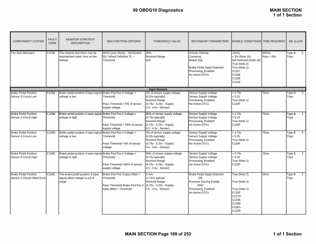
COMPONENT/ SYSTEM FAULT CODE
MONITOR STRATEGY DESCRIPTION MALFUNCTION CRITERIA THRESHOLD VALUE SECONDARY PARAMETERS ENABLE CONDITIONS TIME REQUIRED MIL ILLUM.
Tire Size Mismatch C122E This detects that there may be mismatched sized tires on the vehicle
|WSS (one wheel) – WSS(other 3)| / Wheel Vel(other 3) > Threshold
25%Nominal Range:N/A
Vehicle VelocityCorneringWheel Slip
Brake Pedal Apply DetectedProcessing_EnabledNo Active DTCs
>4m/s< 3% (Note 10)Not Detected (Note 10)True (Note 2)True (Note 1)C1207C1208C1209C1210
500msPass = 60s
Type B 2 Trips
Brake Pedal Position Sensor 3 Circuit Low
C129A Brake pedal position 3 input signal voltage is low.
Brake Ped Pos 3 Voltage < Threshold
Pass Threshold > 5% of sensor supply voltage
5% of sensor supply voltage(0.25v typically)Nominal Range:(4.75v - 5.25v - Supply0.5 - 4.5v - Sensor)
Sensor Supply VoltageSensor Supply VoltageProcessing_EnabledNo Active DTCs
> 4.75v < 5.25True (Note 1)C120F
75ms Type B 2 Trips
Brake Pedal Position C129B Brake pedal position 3 input signal Brake Ped Pos 3 Voltage > 95% of sensor supply voltage Sensor Supply Voltage > 4.75v 75ms Type B 2
Input Sensors
Brake Pedal Position Sensor 3 Circuit High
C129B Brake pedal position 3 input signal voltage is high.
Brake Ped Pos 3 Voltage > Threshold
Pass Threshold > 95% of sensor supply voltage
95% of sensor supply voltage(4.75v typically)Nominal Range:(4.75v - 5.25v - Supply0.5 - 4.5v - Sensor)
Sensor Supply VoltageSensor Supply VoltageProcessing_EnabledNo Active DTCs
> 4.75v < 5.25True (Note 1)C120F
75ms Type B 2 Trips
Brake Pedal Position Sensor 4 Circuit Low
C129D Brake pedal position 4 input signal voltage is low.
Brake Ped Pos 4 Voltage < Threshold
Pass Threshold >5% of sensor voltage
5% of sensor supply voltage(0.25v typically)Nominal Range:(4.75v - 5.25v - Supply4.5 - 0.5v - Sensor)
Sensor Supply VoltageSensor Supply VoltageProcessing_EnabledNo Active DTCs
> 4.75v < 5.25True (Note 1)C120F
75ms Type B 2 Trips
Brake Pedal Position Sensor 4 Circuit High
C129E Brake pedal position 4 input signal voltage is high.
Brake Ped Pos 4 Voltage > Threshold
Pass Threshold <95% of sensor supply voltage
95% of sensor supply voltage(4.75v typically)Nominal Range:(4.75v - 5.25v - Supply4.5 - 0.5v - Sensor)
Sensor Supply VoltageSensor Supply VoltageProcessing_EnabledNo Active DTCs
> 4.75v < 5.25True (Note 1)C120F
75ms Type B 2 Trips
Brake Pedal Position Sensor 3 Circuit Offset Error
C129C The brake pedal position 3 input signal offset voltage is out of range
Brake Ped Pos 3 input offset > Threshold
Pass Threshold Brake Ped Pos 3 input offset < Threshold
5 mm(>1.07v typical)Nominal Range:(4.75v - 5.25v - Supply0.5 - 4.5v - Sensor)
Brake Pedal Apply Detected ORPressure Zeroing Enable ANDProcessing_EnabledNo Active DTCs
True (Note 2)
True (Note 3)
True (Note 1)C120FC127DC129AC129BC12E5C12F8
15ms Type B 2 Trips
09 OBDG10 Diagnostics MAIN SECTION1 of 1 Section
MAIN SECTION Page 189 of 253 1 of 1 Section
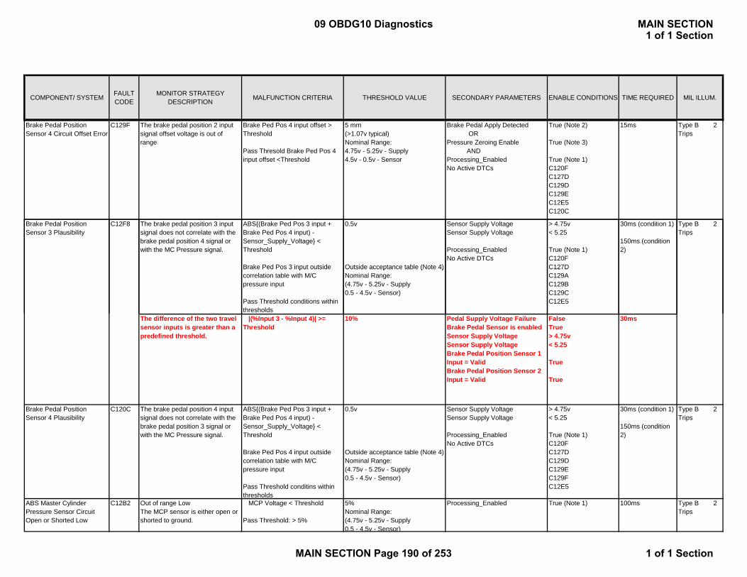
COMPONENT/ SYSTEM FAULT CODE
MONITOR STRATEGY DESCRIPTION MALFUNCTION CRITERIA THRESHOLD VALUE SECONDARY PARAMETERS ENABLE CONDITIONS TIME REQUIRED MIL ILLUM.
Brake Pedal Position Sensor 4 Circuit Offset Error
C129F The brake pedal position 2 input signal offset voltage is out of range
Brake Ped Pos 4 input offset > Threshold
Pass Thresold Brake Ped Pos 4 input offset <Threshold
5 mm(>1.07v typical)Nominal Range:4.75v - 5.25v - Supply4.5v - 0.5v - Sensor
Brake Pedal Apply Detected ORPressure Zeroing Enable ANDProcessing_EnabledNo Active DTCs
True (Note 2)
True (Note 3)
True (Note 1)C120FC127DC129DC129EC12E5C120C
15ms Type B 2 Trips
Brake Pedal Position Sensor 3 Plausibility
C12F8 The brake pedal position 3 input signal does not correlate with the brake pedal position 4 signal or with the MC Pressure signal.
ABS{(Brake Ped Pos 3 input + Brake Ped Pos 4 input) - Sensor_Supply_Voltage} < Threshold
Brake Ped Pos 3 input outside
0.5v
Outside acceptance table (Note 4)
Sensor Supply VoltageSensor Supply Voltage
Processing_EnabledNo Active DTCs
> 4.75v < 5.25
True (Note 1)C120FC127D
30ms (condition 1)
150ms (condition 2)
Type B 2 Trips
Brake Ped Pos 3 input outside correlation table with M/C pressure input
Pass Threshold conditions within thresholds
Outside acceptance table (Note 4)Nominal Range:(4.75v - 5.25v - Supply0.5 - 4.5v - Sensor)
C127DC129AC129BC129CC12E5
The difference of the two travel sensor inputs is greater than a predefined threshold.
|(%Input 3 - %Input 4)| >= Threshold
10% Pedal Supply Voltage FailureBrake Pedal Sensor is enabledSensor Supply VoltageSensor Supply VoltageBrake Pedal Position Sensor 1 Input = ValidBrake Pedal Position Sensor 2 Input = Valid
FalseTrue > 4.75v < 5.25
True
True
30ms
Brake Pedal Position Sensor 4 Plausibility
C120C The brake pedal position 4 input signal does not correlate with the brake pedal position 3 signal or with the MC Pressure signal.
ABS{(Brake Ped Pos 3 input + Brake Ped Pos 4 input) - Sensor_Supply_Voltage} < Threshold
Brake Ped Pos 4 input outside correlation table with M/C pressure input
Pass Threshold conditins within thresholds
0.5v
Outside acceptance table (Note 4)Nominal Range:(4.75v - 5.25v - Supply0.5 - 4.5v - Sensor)
Sensor Supply VoltageSensor Supply Voltage
Processing_EnabledNo Active DTCs
> 4.75v < 5.25
True (Note 1)C120FC127DC129DC129EC129FC12E5
30ms (condition 1)
150ms (condition 2)
Type B 2 Trips
ABS Master Cylinder Pressure Sensor Circuit Open or Shorted Low
C12B2 Out of range LowThe MCP sensor is either open or shorted to ground.
MCP Voltage < Threshold
Pass Threshold: > 5%
5%Nominal Range:(4.75v - 5.25v - Supply0.5 - 4.5v - Sensor)
Processing_Enabled True (Note 1) 100ms Type B 2 Trips
09 OBDG10 Diagnostics MAIN SECTION1 of 1 Section
MAIN SECTION Page 190 of 253 1 of 1 Section

COMPONENT/ SYSTEM FAULT CODE
MONITOR STRATEGY DESCRIPTION MALFUNCTION CRITERIA THRESHOLD VALUE SECONDARY PARAMETERS ENABLE CONDITIONS TIME REQUIRED MIL ILLUM.
ABS Master Cylinder Pressure Sensor Circuit Shorted High
C12B3 The MCP sensor signal is shorted high.
MCP Voltage > Supply Threshold
Pass Threshold: < 95%
95%Nominal Range:(4.75v - 5.25v - Supply0.5 - 4.5v - Sensor)
Processing_Enabled True (Note 1) 100ms Type B 2 Trips
ABS Master Cylinder Pressure Sensor and Brake Pedal Position Sensor Correlation
C12B1 The Master Cylinder Pressure sensor reading does not correlate with the pedal travel sensor readings.
M/C pressure input outside correlation table with Brake Ped Pos x inputs
M/C Pressure has not changed by more than Threshold 1 while pedal travel inputs have changed more than Threshold 2
Outside acceptance table (Note 4)
Threshold 1 = 50.0 kPaThreshold 2 =2.0 mm (rod)
Processing_EnabledM/C Pressure signal stableNo Active DTCs
True (Note 1)True (Note 5)C120CC120FC12B2C12B3C12B4C128BC128EC127DC129AC129BC129CC129D
150ms (condition 1)
100ms (condition 2)
Type B 2 Trips
C129DC129EC129FC12E5C12F8
ABS Master Cylinder Pressure Sensor Performance
C12B4 An MCP erratic condition exist if the ohmic fault status has changed since the last time the ohmic check was performed.
Transitions from Valid to Open/Shorted State
Pass Threshold: Transitions do not occur.
Successive LoopsNominal Range:(4.75v - 5.25v - Supply0.5 - 4.5v - Sensor)
Processing_EnabledNo active DTCs:
True (Note 1)C12B2C12B3
100msPass =150ms
Type B 2 Trips
ABS Master Cylinder Pressure Sensor Offset Error
C128B The MCP sensor’s input signal offset is out of range.
MCP Offset > Threshold 800 kPa(0.7v typically)Nominal Range:(4.75v - 5.25v - Supply0.5 - 4.5v - Sensor)
(Brake SwitchVeh AccelPump Motor) orBrake Pedal Apply Detected ANDProcessing_EnabledNo active DTCs:
False> 0.4m/s2Not Active
True (Note 2)
True (Note 1)C12B2C12B3C128E
20ms Type B 2 Trips
ABS Master Cylinder Pressure Sensor Raw Offset Error
C128E The MCP sensor’s raw offset is out of range.
MCP Raw Offset > Threshold 5000 kPa(1.64v typical)Nominal Range:(4.75v - 5.25v - Supply0.5 - 4.5v - Sensor)
Brake ControlVehicle Acceleration Vehicle VelocityAccelerator Pedal PositionBrake SwitchProcessing_EnabledNo active DTCs:
False (Note 6)> -0.5m/s/s> 2.0m/s< 10%FalseTrue (Note 1)C12B2C12B3C128E
1s Type B 2 Trips
09 OBDG10 Diagnostics MAIN SECTION1 of 1 Section
MAIN SECTION Page 191 of 253 1 of 1 Section

COMPONENT/ SYSTEM FAULT CODE
MONITOR STRATEGY DESCRIPTION MALFUNCTION CRITERIA THRESHOLD VALUE SECONDARY PARAMETERS ENABLE CONDITIONS TIME REQUIRED MIL ILLUM.
Brake Pedal Position Sensor Power Circuit Low
C120F The supply to the pedal position sensor is shorted to ground.
Pedal supply voltage < Threshold
Pass Threshold > 0.5v
0.5v Processing_Enabled True (Note 1) 30ms Type B 2 Trips
Brake Pedal Position Sensor Reference Circuit
C12E5 Determines if the voltage supply to the pedal sensor is out of range.
Pedal supply voltage < Threshold Low
Pedal supply voltage > Threshold High
Pass Threshold4.75 < Volt <5.25
Low = 4.75v
High = 5.25vNominal Range:(N/A)
Processing_Enabled True (Note 1) 30ms Type B 2 Trips
ABS Sensor Reference Output Circuit
C12E4 Determines if the internal 5v voltage supply is out of range.
Internal supply voltage < Threshold Low
Internal supply voltage >
Low = 4.75v
High = 5.25vNominal Range:
Processing_Enabled True (Note 1) 30ms Type B 2 Trips
Internal Pressure Sensors
Internal supply voltage > Threshold High
Pass Threshold4.75 < Volt <5.25
Nominal Range:(N/A)
ABS HPA Pressure Sensor Circuit Open or Shorted Low
C12B6 Out of range low.The HPA pressure sensor is either open or shorted to ground.
HPA Voltage < Threshold
Pass Threshold: > 5%
5%Nominal Range:(4.75v - 5.25v - Supply0.5 - 4.5v - Sensor)
Processing_Enabled True (Note 1) 100ms Type B 2 Trips
ABS HPA Pressure Sensor Circuit Shorted High
C12B7 The HPA pressure sensor signal is shorted high.
HPA Voltage > Supply Threshold
Pass Threshold: < 95%
95%Nominal Range:(4.75v - 5.25v - Supply0.5 - 4.5v - Sensor)
Processing_Enabled True (Note 1) 100ms Type B 2 Trips
ABS HPA Pressure Sensor Erratic
C12B8 An HPA pressure sensor erratic condition exist if the ohmic fault status has changed since the last time the ohmic check was performed
Transitions from Valid to Open/Shorted State
Pass Threshold: Transitions do not occur.
Successive LoopsNominal Range:(4.75v - 5.25v - Supply0.5 - 4.5v - Sensor)
Processing_EnabledNo active DTCs:
True (Note 1)C12B6C12B7
100msPass = 150ms
Type B 2 Trips
ABS Regenerative Axle Pressure Sensor Circuit Open or Shorted Low
C12B9 The regen axle pressure sensor is either open or shorted to ground.
Regen Axle Voltage < Threshold
Pass Threshold: > 5%
5%Nominal Range:(4.75v - 5.25v - Supply0.5 - 4.5v - Sensor)
Processing_Enabled True (Note 1) 100ms Type B 2 Trips
ABS Regenerative Axle Pressure Sensor Circuit Shorted High
C12BA The regen axle pressure sensor signal is shorted high.
Regen Axle Voltage > Supply Threshold
Pass Threshold: < 95%
95%Nominal Range:(4.75v - 5.25v - Supply0.5 - 4.5v - Sensor)
Processing_Enabled True (Note 1) 100ms Type B 2 Trips
09 OBDG10 Diagnostics MAIN SECTION1 of 1 Section
MAIN SECTION Page 192 of 253 1 of 1 Section
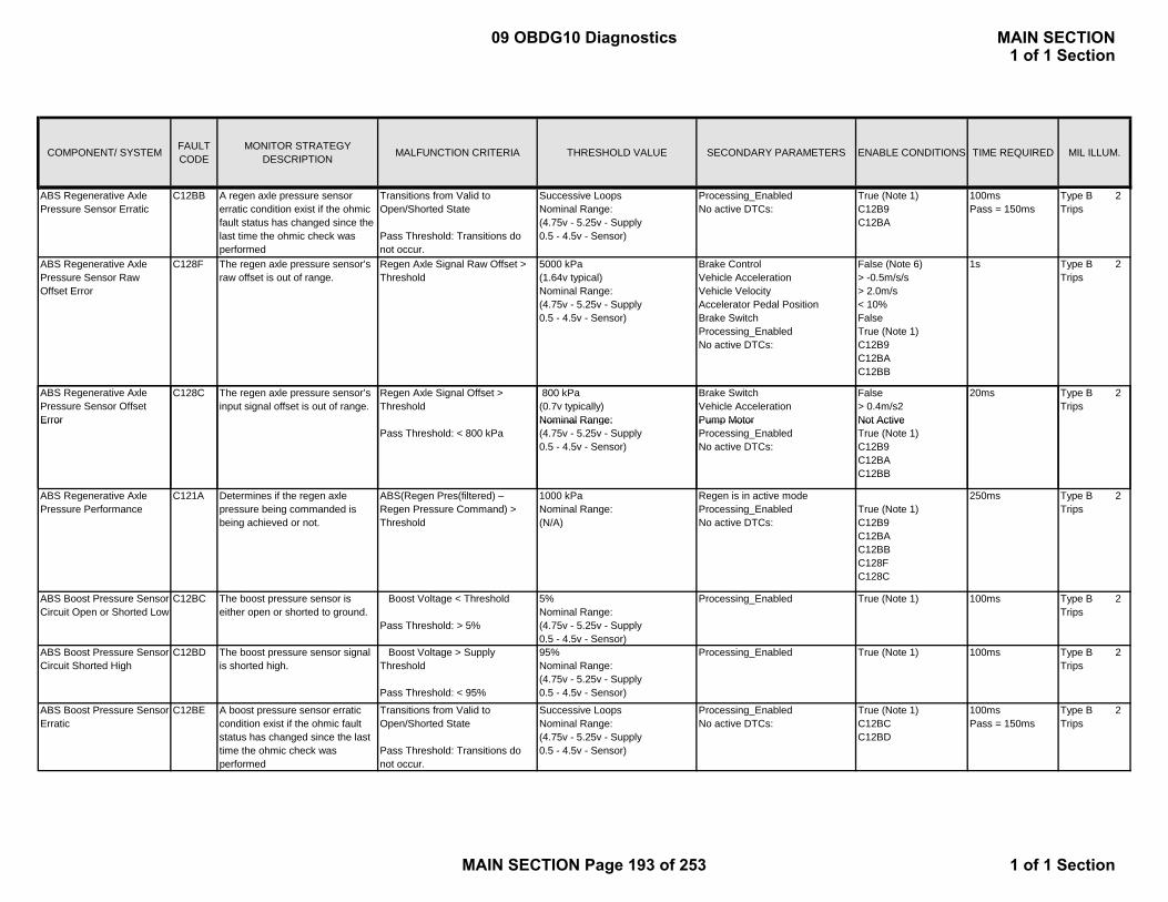
COMPONENT/ SYSTEM FAULT CODE
MONITOR STRATEGY DESCRIPTION MALFUNCTION CRITERIA THRESHOLD VALUE SECONDARY PARAMETERS ENABLE CONDITIONS TIME REQUIRED MIL ILLUM.
ABS Regenerative Axle Pressure Sensor Erratic
C12BB A regen axle pressure sensor erratic condition exist if the ohmic fault status has changed since the last time the ohmic check was performed
Transitions from Valid to Open/Shorted State
Pass Threshold: Transitions do not occur.
Successive LoopsNominal Range:(4.75v - 5.25v - Supply0.5 - 4.5v - Sensor)
Processing_EnabledNo active DTCs:
True (Note 1)C12B9C12BA
100msPass = 150ms
Type B 2 Trips
ABS Regenerative Axle Pressure Sensor Raw Offset Error
C128F The regen axle pressure sensor’s raw offset is out of range.
Regen Axle Signal Raw Offset > Threshold
5000 kPa(1.64v typical)Nominal Range:(4.75v - 5.25v - Supply0.5 - 4.5v - Sensor)
Brake ControlVehicle Acceleration Vehicle VelocityAccelerator Pedal PositionBrake SwitchProcessing_EnabledNo active DTCs:
False (Note 6)> -0.5m/s/s> 2.0m/s< 10%FalseTrue (Note 1)C12B9C12BAC12BB
1s Type B 2 Trips
ABS Regenerative Axle Pressure Sensor Offset Error
C128C The regen axle pressure sensor’s input signal offset is out of range.
Regen Axle Signal Offset > Threshold
800 kPa(0.7v typically)Nominal Range:
Brake SwitchVehicle AccelerationPump Motor
False> 0.4m/s2Not Active
20ms Type B 2 Trips
ErrorPass Threshold: < 800 kPa
Nominal Range:(4.75v - 5.25v - Supply0.5 - 4.5v - Sensor)
Pump MotorProcessing_EnabledNo active DTCs:
Not ActiveTrue (Note 1)C12B9C12BAC12BB
ABS Regenerative Axle Pressure Performance
C121A Determines if the regen axle pressure being commanded is being achieved or not.
ABS(Regen Pres(filtered) – Regen Pressure Command) > Threshold
1000 kPaNominal Range:(N/A)
Regen is in active modeProcessing_EnabledNo active DTCs:
True (Note 1)C12B9C12BAC12BBC128FC128C
250ms Type B 2 Trips
ABS Boost Pressure Sensor Circuit Open or Shorted Low
C12BC The boost pressure sensor is either open or shorted to ground.
Boost Voltage < Threshold
Pass Threshold: > 5%
5%Nominal Range:(4.75v - 5.25v - Supply0.5 - 4.5v - Sensor)
Processing_Enabled True (Note 1) 100ms Type B 2 Trips
ABS Boost Pressure Sensor Circuit Shorted High
C12BD The boost pressure sensor signal is shorted high.
Boost Voltage > Supply Threshold
Pass Threshold: < 95%
95%Nominal Range:(4.75v - 5.25v - Supply0.5 - 4.5v - Sensor)
Processing_Enabled True (Note 1) 100ms Type B 2 Trips
ABS Boost Pressure Sensor Erratic
C12BE A boost pressure sensor erratic condition exist if the ohmic fault status has changed since the last time the ohmic check was performed
Transitions from Valid to Open/Shorted State
Pass Threshold: Transitions do not occur.
Successive LoopsNominal Range:(4.75v - 5.25v - Supply0.5 - 4.5v - Sensor)
Processing_EnabledNo active DTCs:
True (Note 1)C12BCC12BD
100msPass = 150ms
Type B 2 Trips
09 OBDG10 Diagnostics MAIN SECTION1 of 1 Section
MAIN SECTION Page 193 of 253 1 of 1 Section

COMPONENT/ SYSTEM FAULT CODE
MONITOR STRATEGY DESCRIPTION MALFUNCTION CRITERIA THRESHOLD VALUE SECONDARY PARAMETERS ENABLE CONDITIONS TIME REQUIRED MIL ILLUM.
ABS Boost Pressure Sensor Raw Offset Error
C128D The boost pressure sensor’s raw offset is out of range.
Boost Signal Raw Offset > Threshold
5000 kPa(1.64v typical)Nominal Range:(4.75v - 5.25v - Supply0.5 - 4.5v - Sensor)
Brake ControlVehicle Acceleration Vehicle VelocityAccelerator Pedal PositionBrake SwitchProcessing_EnabledNo active DTCs:
False (Note 6)> -0.5m/s/s> 2.0m/s< 10%FalseTrue (Note 1)C12BCC12BDC12BE
1s Type B 2 Trips
ABS Boost Pressure Sensor Offset Error
C128A The boost pressure sensor’s input signal offset is out of range.
Boost Signal Offset > Threshold
Pass Threshold: < 800 kPa
800 kPa(0.7v typically)Nominal Range:(4.75v - 5.25v - Supply0.5 - 4.5v - Sensor)
Brake SwitchVehicle AccelerationPump MotorProcessing_EnabledNo active DTCs:
False> 0.4m/s2Not ActiveTrue (Note 1)C12BCC12BDC12BE
20ms Type B 2 Trips
ABS B P C120A D i if h b B P Diff(BPD) |B Th hld1 3000 kP P i E bl d T (N 1) 00 T B 2ABS Boost Pressure Performance
C120A Determines if the boost pressure being commanded is being achieved or not.
Boost Pres Diff(BPD) = |Boost Pres(filtered, zeroed) – test command|
With VSC or TC or ABS active: BPD > Thrshld1
Without VSC and TC and ABS active: BPD > Thrshld2
Thrshld1 = 3000 kPa
Thrshld2 = 1500 kPaNominal Range:(N/A)
Processing_EnabledNo active DTCs:
True (Note 1)C12B6C12B7C12B8C12BCC12BDC12BEC128AC128DC127DC12E4
500ms Type B 2 Trips
ABS Boost Pressure Sensor and Regenerative Axle Pressure Sensor Correlation
C12F7 The regen axle pressure sensor is checked with the boost pressure sensor by equalizing pressure at the two sensors and comparing their difference to a trimmed threshold. The pressures are equalized by controlling the regen axle valves during the test.
(Regen axle pressure – Boost pressure) > Threshold
Pass Threshold: < 500 kPa
500 kPa All Wheel Speeds = 0Brake Pedal Apply DetectedBoost PressureProcessing_EnabledNo active DTCs:
> 1sTrue (Note 2) > 150 kPaTrue (Note 1)C127DC128AC128CC128DC128FC12B9C12BAC12BBC12BCC12BDC12BEC12E4C12F7
100 ms Type B 2 Trips
09 OBDG10 Diagnostics MAIN SECTION1 of 1 Section
MAIN SECTION Page 194 of 253 1 of 1 Section
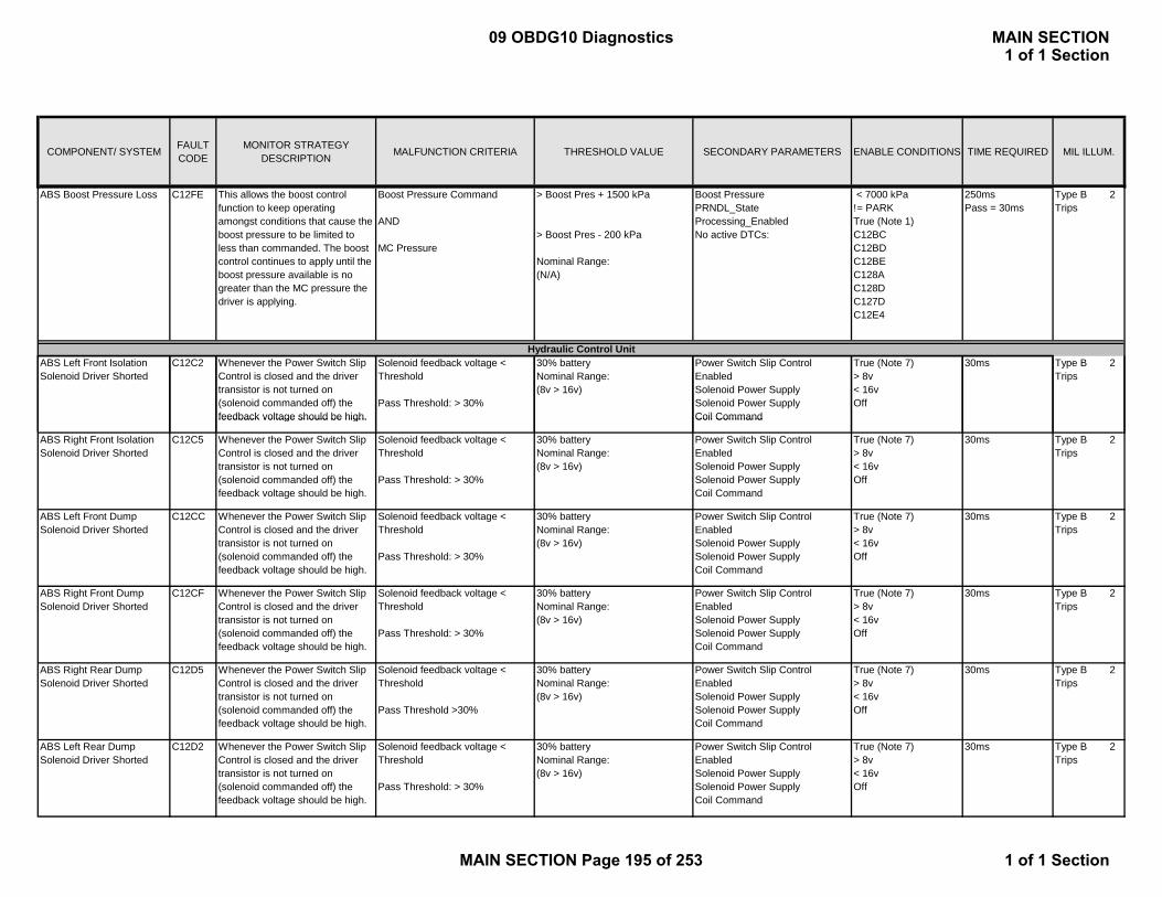
COMPONENT/ SYSTEM FAULT CODE
MONITOR STRATEGY DESCRIPTION MALFUNCTION CRITERIA THRESHOLD VALUE SECONDARY PARAMETERS ENABLE CONDITIONS TIME REQUIRED MIL ILLUM.
ABS Boost Pressure Loss C12FE This allows the boost control function to keep operating amongst conditions that cause the boost pressure to be limited to less than commanded. The boost control continues to apply until the boost pressure available is no greater than the MC pressure the driver is applying.
Boost Pressure Command
AND
MC Pressure
> Boost Pres + 1500 kPa
> Boost Pres - 200 kPa
Nominal Range:(N/A)
Boost PressurePRNDL_StateProcessing_EnabledNo active DTCs:
< 7000 kPa!= PARKTrue (Note 1)C12BCC12BDC12BEC128AC128DC127DC12E4
250msPass = 30ms
Type B 2 Trips
ABS Left Front Isolation Solenoid Driver Shorted
C12C2 Whenever the Power Switch Slip Control is closed and the driver transistor is not turned on (solenoid commanded off) the feedback voltage should be high.
Solenoid feedback voltage < Threshold
Pass Threshold: > 30%
30% batteryNominal Range:(8v > 16v)
Power Switch Slip Control EnabledSolenoid Power SupplySolenoid Power Supply Coil Command
True (Note 7)> 8v < 16vOff
30ms Type B 2 Trips
Hydraulic Control Unit
feedback voltage should be high. Coil Command
ABS Right Front Isolation Solenoid Driver Shorted
C12C5 Whenever the Power Switch Slip Control is closed and the driver transistor is not turned on (solenoid commanded off) the feedback voltage should be high.
Solenoid feedback voltage < Threshold
Pass Threshold: > 30%
30% batteryNominal Range:(8v > 16v)
Power Switch Slip Control EnabledSolenoid Power SupplySolenoid Power Supply Coil Command
True (Note 7)> 8v < 16vOff
30ms Type B 2 Trips
ABS Left Front Dump Solenoid Driver Shorted
C12CC Whenever the Power Switch Slip Control is closed and the driver transistor is not turned on (solenoid commanded off) the feedback voltage should be high.
Solenoid feedback voltage < Threshold
Pass Threshold: > 30%
30% batteryNominal Range:(8v > 16v)
Power Switch Slip Control EnabledSolenoid Power SupplySolenoid Power Supply Coil Command
True (Note 7)> 8v < 16vOff
30ms Type B 2 Trips
ABS Right Front Dump Solenoid Driver Shorted
C12CF Whenever the Power Switch Slip Control is closed and the driver transistor is not turned on (solenoid commanded off) the feedback voltage should be high.
Solenoid feedback voltage < Threshold
Pass Threshold: > 30%
30% batteryNominal Range:(8v > 16v)
Power Switch Slip Control EnabledSolenoid Power SupplySolenoid Power Supply Coil Command
True (Note 7)> 8v < 16vOff
30ms Type B 2 Trips
ABS Right Rear Dump Solenoid Driver Shorted
C12D5 Whenever the Power Switch Slip Control is closed and the driver transistor is not turned on (solenoid commanded off) the feedback voltage should be high.
Solenoid feedback voltage < Threshold
Pass Threshold >30%
30% batteryNominal Range:(8v > 16v)
Power Switch Slip Control EnabledSolenoid Power SupplySolenoid Power Supply Coil Command
True (Note 7)> 8v < 16vOff
30ms Type B 2 Trips
ABS Left Rear Dump Solenoid Driver Shorted
C12D2 Whenever the Power Switch Slip Control is closed and the driver transistor is not turned on (solenoid commanded off) the feedback voltage should be high.
Solenoid feedback voltage < Threshold
Pass Threshold: > 30%
30% batteryNominal Range:(8v > 16v)
Power Switch Slip Control EnabledSolenoid Power SupplySolenoid Power Supply Coil Command
True (Note 7)> 8v < 16vOff
30ms Type B 2 Trips
09 OBDG10 Diagnostics MAIN SECTION1 of 1 Section
MAIN SECTION Page 195 of 253 1 of 1 Section

COMPONENT/ SYSTEM FAULT CODE
MONITOR STRATEGY DESCRIPTION MALFUNCTION CRITERIA THRESHOLD VALUE SECONDARY PARAMETERS ENABLE CONDITIONS TIME REQUIRED MIL ILLUM.
ABS Base Brake Open Solenoid Driver Shorted
C12D8 Whenever the Power Switch Base Brake is closed and the driver transistor is not turned on (solenoid commanded off) the feedback voltage should be high.
Solenoid feedback voltage < Threshold
Pass Threshold >30%
30% batteryNominal Range:(8v > 16v)
Power Switch Base Brake EnabledSolenoid Power SupplySolenoid Power Supply Coil Command
True (Note 8)> 8v < 16vOff
30ms Type B 2 Trips
ABS Base Brake Closed Solenoid Driver Shorted
C12DB Whenever the Power Switch Base Brake is closed and the driver transistor is not turned on (solenoid commanded off) the feedback voltage should be high.
Solenoid feedback voltage < Threshold
Pass Threshold >30%
30% batteryNominal Range:(8v > 16v)
Power Switch Base Brake EnabledSolenoid Power SupplySolenoid Power Supply Coil Command
True (Note 8)> 8v < 16vOff
30ms Type B 2 Trips
ABS Left Rear Dump Solenoid Circuit Shorted
C12D1 Whenever the Power Switch Slip Control is closed and the driver transistor is turned on (solenoid commanded on) the feedback voltage should be low.
Solenoid feedback voltage > Threshold
Pass Threshold: < Threshold
30% of battey (Solenoid in ON/OFF Mode)
85% of batter (Solenoid in PWM Mode)Nominal Range:
Power Switch Slip Control EnabledSolenoid Power SupplySolenoid Power Supply Coil Command
True (Note 7)> 8v < 16vOn
15ms (Solenoid in ON/OFF Mode)20ms (Solenoid in PWM Mode)Pass = 35ms
Type B 2 Trips
Nominal Range:(8v > 16v)
ABS Right Rear Dump Solenoid Circuit Shorted
C12D4 Whenever the Power Switch Slip Control is closed and the driver transistor is turned on (solenoid commanded on) the feedback voltage should be low.
Solenoid feedback voltage > Threshold
Pass Threshold: < Threshold
30% of battey (Solenoid in ON/OFF Mode)
85% of batter (Solenoid in PWM Mode)Nominal Range:(8v > 16v)
Power Switch Slip Control EnabledSolenoid Power SupplySolenoid Power Supply Coil Command
True (Note 7)> 8v < 16vOn
15ms (Solenoid in ON/OFF Mode)20ms (Solenoid in PWM Mode)Pass = 35ms
Type B 2 Trips
ABS Base Brake Open Solenoid Circuit Shorted
C12D7 Whenever the Power Switch Base Brake is closed and the driver transistor is turned on (solenoid commanded on) the feedback voltage should be low.
Solenoid feedback voltage > Threshold
Pass Threshold: < Threshold
30% of battey (Solenoid in ON/OFF Mode)
85% of batter (Solenoid in PWM Mode)Nominal Range:(8v > 16v)
Power Switch Slip Control EnabledSolenoid Power SupplySolenoid Power Supply Coil Command
True (Note 7)> 8v < 16vOn
15ms (Solenoid in ON/OFF Mode)20ms (Solenoid in PWM Mode)Pass = 35ms
Type B 2 Trips
ABS Base Brake Closed Solenoid Circuit Shorted
C12DA Whenever the Power Switch Base Brake is closed and the driver transistor is turned on (solenoid commanded on) the feedback voltage should be low.
Solenoid feedback voltage > Threshold
Pass Threshold: < Threshold
30% of battey (Solenoid in ON/OFF Mode)
85% of batter (Solenoid in PWM Mode)Nominal Range:(8v > 16v)
Power Switch Slip Control EnabledSolenoid Power SupplySolenoid Power Supply Coil Command
True (Note 7)> 8v < 16vOn
15ms (Solenoid in ON/OFF Mode)20ms (Solenoid in PWM Mode)Pass = 35ms
Type B 2 Trips
ABS Left Rear Dump Solenoid Circuit Open
C12D0 Whenever the Power Switch Slip Control is closed and the driver transistor is not turned on (solenoid commanded off) the feedback voltage should be high.
Solenoid feedback voltage < ThresholdSolenoid feedback voltage > Threshold
Pass Threshold: > 80%Pass Threshold: < 30%
80% battery30% batteryNominal Range:(8v > 16v)
Power Switch Slip Control EnabledSolenoid Power SupplySolenoid Power Supply Coil Command
True (Note 7)> 8v < 16vOff
30ms Type B 2 Trips
09 OBDG10 Diagnostics MAIN SECTION1 of 1 Section
MAIN SECTION Page 196 of 253 1 of 1 Section
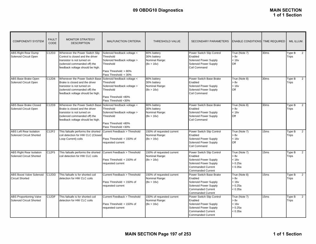
COMPONENT/ SYSTEM FAULT CODE
MONITOR STRATEGY DESCRIPTION MALFUNCTION CRITERIA THRESHOLD VALUE SECONDARY PARAMETERS ENABLE CONDITIONS TIME REQUIRED MIL ILLUM.
ABS Right Rear Dump Solenoid Circuit Open
C12D3 Whenever the Power Switch Slip Control is closed and the driver transistor is not turned on (solenoid commanded off) the feedback voltage should be high.
Solenoid feedback voltage < ThresholdSolenoid feedback voltage > Threshold
Pass Threshold: > 80%Pass Threshold: < 30%
80% battery30% batteryNominal Range:(8v > 16v)
Power Switch Slip Control EnabledSolenoid Power SupplySolenoid Power Supply Coil Command
True (Note 7)> 8v < 16vOff
30ms Type B 2 Trips
ABS Base Brake Open Solenoid Circuit Open
C12D6 Whenever the Power Switch Base Brake is closed and the driver transistor is not turned on (solenoid commanded off) the feedback voltage should be high.
Solenoid feedback voltage < ThresholdSolenoid feedback voltage > Threshold
Pass Threshold >80%Pass Threshold <30%
80% battery30% batteryNominal Range:(8v > 16v)
Power Switch Base Brake EnabledSolenoid Power SupplySolenoid Power Supply Coil Command
True (Note 8)> 8v < 16vOff
30ms Type B 2 Trips
ABS Base Brake Closed Solenoid Circuit Open
C12D9 Whenever the Power Switch Base Brake is closed and the driver transistor is not turned on
Solenoid feedback voltage < ThresholdSolenoid feedback voltage >
80% battery30% batteryNominal Range:
Power Switch Base Brake EnabledSolenoid Power Supply
True (Note 8)> 8v < 16v
30ms Type B 2 Trips
(solenoid commanded off) the feedback voltage should be high.
gThreshold
Pass Threshold >80%Pass Threshold <30%
g(8v > 16v)
pp ySolenoid Power Supply Coil Command
Off
ABS Left Rear Isolation Solenoid Circuit Shorted
C12F2 This failsafe performs the shorted coil detection for HW CLC (Closed Loop Current) coils
Current Feedback > Threshold
Pass Threshold: < 150% of requested current
150% of requested currentNominal Range:(8v > 16v)
Power Switch Slip Control EnabledSolenoid Power SupplySolenoid Power Supply Coil Command
True (Note 7)> 8v < 16vOff
15ms Type B 2 Trips
ABS Right Rear Isolation Solenoid Circuit Shorted
C12F5 This failsafe performs the shorted coil detection for HW CLC coils
Current Feedback > Threshold
Pass Threshold: < 150% of requested current
150% of requested currentNominal Range:(8v > 16v)
Power Switch Slip Control EnabledSolenoid Power SupplySolenoid Power SupplyCommanded CurrentCommanded Current
True (Note 7)> 8v < 16v> 0.25a < 0.35a
15ms Type B 2 Trips
ABS Boost Valve Solenoid Circuit Shorted
C12DD This failsafe is for shorted coil detection for HW CLC coils
Current Feedback > Threshold
Pass Threshold: < 150% of requested current
150% of requested currentNominal Range:(8v > 16v)
Power Switch Base Brake EnabledSolenoid Power SupplySolenoid Power SupplyCommanded CurrentCommanded Current
True (Note 8)> 8v < 16v> 0.25a < 0.35a
15ms Type B 2 Trips
ABS Proportioning Valve Solenoid Circuit Shorted
C12DF This failsafe is for shorted coil detection for HW CLC coils
Current Feedback > Threshold
Pass Threshold: < 150% of requested current
150% of requested currentNominal Range:(8v > 16v)
Power Switch Slip Control EnabledSolenoid Power SupplySolenoid Power SupplyCommanded CurrentCommanded Current
True (Note 7)> 8v < 16v> 0.25a < 0.35a
15ms Type B 2 Trips
09 OBDG10 Diagnostics MAIN SECTION1 of 1 Section
MAIN SECTION Page 197 of 253 1 of 1 Section
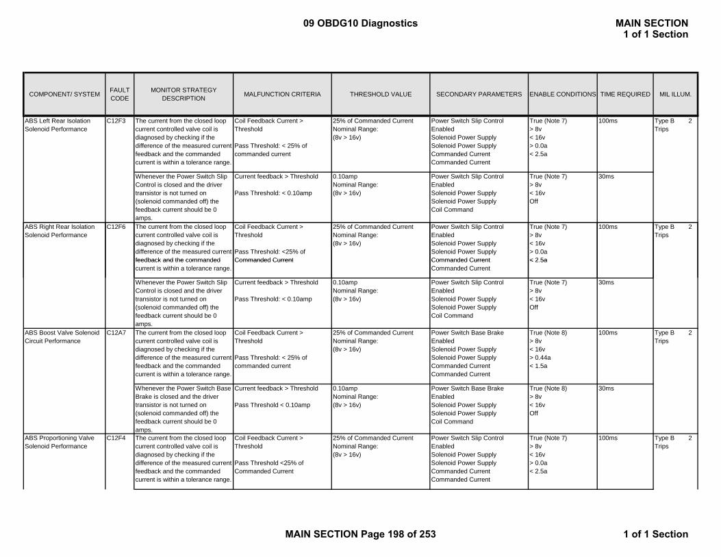
COMPONENT/ SYSTEM FAULT CODE
MONITOR STRATEGY DESCRIPTION MALFUNCTION CRITERIA THRESHOLD VALUE SECONDARY PARAMETERS ENABLE CONDITIONS TIME REQUIRED MIL ILLUM.
The current from the closed loop current controlled valve coil is diagnosed by checking if the difference of the measured current feedback and the commanded current is within a tolerance range.
Coil Feedback Current > Threshold
Pass Threshold: < 25% of commanded current
25% of Commanded CurrentNominal Range:(8v > 16v)
Power Switch Slip Control EnabledSolenoid Power SupplySolenoid Power SupplyCommanded CurrentCommanded Current
True (Note 7)> 8v< 16v> 0.0a < 2.5a
100ms
Whenever the Power Switch Slip Control is closed and the driver transistor is not turned on (solenoid commanded off) the feedback current should be 0 amps.
Current feedback > Threshold
Pass Threshold: < 0.10amp
0.10ampNominal Range:(8v > 16v)
Power Switch Slip Control EnabledSolenoid Power SupplySolenoid Power Supply Coil Command
True (Note 7)> 8v < 16vOff
30ms
The current from the closed loop current controlled valve coil is diagnosed by checking if the difference of the measured current feedback and the commanded
Coil Feedback Current > Threshold
Pass Threshold: <25% of Commanded Current
25% of Commanded CurrentNominal Range:(8v > 16v)
Power Switch Slip Control EnabledSolenoid Power SupplySolenoid Power SupplyCommanded Current
True (Note 7)> 8v< 16v> 0.0a < 2 5a
100ms
Type B 2 Trips
Type B 2 Trips
ABS Right Rear Isolation Solenoid Performance
C12F6
ABS Left Rear Isolation Solenoid Performance
C12F3
feedback and the commanded current is within a tolerance range.
Commanded Current Commanded CurrentCommanded Current
< 2.5a
Whenever the Power Switch Slip Control is closed and the driver transistor is not turned on (solenoid commanded off) the feedback current should be 0 amps.
Current feedback > Threshold
Pass Threshold: < 0.10amp
0.10ampNominal Range:(8v > 16v)
Power Switch Slip Control EnabledSolenoid Power SupplySolenoid Power Supply Coil Command
True (Note 7)> 8v < 16vOff
30ms
The current from the closed loop current controlled valve coil is diagnosed by checking if the difference of the measured current feedback and the commanded current is within a tolerance range.
Coil Feedback Current > Threshold
Pass Threshold: < 25% of commanded current
25% of Commanded CurrentNominal Range:(8v > 16v)
Power Switch Base Brake EnabledSolenoid Power SupplySolenoid Power Supply Commanded CurrentCommanded Current
True (Note 8)> 8v< 16v> 0.44a < 1.5a
100ms
Whenever the Power Switch Base Brake is closed and the driver transistor is not turned on (solenoid commanded off) the feedback current should be 0 amps.
Current feedback > Threshold
Pass Threshold < 0.10amp
0.10ampNominal Range:(8v > 16v)
Power Switch Base Brake EnabledSolenoid Power SupplySolenoid Power Supply Coil Command
True (Note 8)> 8v < 16vOff
30ms
The current from the closed loop current controlled valve coil is diagnosed by checking if the difference of the measured current feedback and the commanded current is within a tolerance range.
Coil Feedback Current > Threshold
Pass Threshold <25% of Commanded Current
25% of Commanded CurrentNominal Range:(8v > 16v)
Power Switch Slip Control EnabledSolenoid Power SupplySolenoid Power SupplyCommanded CurrentCommanded Current
True (Note 7)> 8v< 16v> 0.0a < 2.5a
100ms Type B 2 Trips
Type B 2 Trips
ABS Boost Valve Solenoid Circuit Performance
C12F4ABS Proportioning Valve Solenoid Performance
C12A7
09 OBDG10 Diagnostics MAIN SECTION1 of 1 Section
MAIN SECTION Page 198 of 253 1 of 1 Section

COMPONENT/ SYSTEM FAULT CODE
MONITOR STRATEGY DESCRIPTION MALFUNCTION CRITERIA THRESHOLD VALUE SECONDARY PARAMETERS ENABLE CONDITIONS TIME REQUIRED MIL ILLUM.
Whenever the Power Switch Slip Control is closed and the driver transistor is not turned on (solenoid commanded off) the feedback current should be 0 amps.
Current feedback > Threshold
Pass Threshold <0.10amp
0.10ampNominal Range:(8v > 16v)
Power Switch Slip Control EnabledSolenoid Power SupplySolenoid Power Supply Coil Command
True (Note 7)> 8v < 16vOff
30ms
ABS Pump Motor Run On C12E9 This fault occurs if the Motor is continuously on for greater than 60s for 5 consecutive run times during an ignition cycle.
FSM Run-On Fault counter > Threshold
Pass Threshold < 5
5Nominal Range:(10v > 16v)
Motor_EnabledMotor_ON
True (Note 9)> 60s
15 ms Type B 2 Trips
ABS Pump Motor Locked C12E8 This fault is set when the motor control micro communicates to the system micro that the motor is unable or will not rotate.
FS_Motor_No_Edge_Counter < Threshold
50Nominal Range:(10v > 16v)
Motor_Enabled True (Note 9) 15 ms Type B 2 Trips
ABS Pump Motor Performance
C12E0 This fault checks to see if a condition exists in which the accumulator is not charging
Accumulator Pressure < Threshold
11000 kPaNominal Range:(10v > 16v)
Brake Pedal Apply DetectedMotor_EnabledBoost Pressure < Command +
True (Note 2)True (Note 9)True
100ms Type B 2 Trips
accumulator is not chargingPass Threshold > 12000 kPa
(10v > 16v) Boost_Pressure < Command + 150 kPaNo active DTCs:
True
C12B6C12B7C12B8C127DC12E4
EBCM Device Voltage Low C12E1 System voltage is too low for certain operations.
System voltage < Threshold
Pass Threshold Volt >9v
9vNominal Range:(N/A)
Ignition != Crank 100ms Special Type C NO MIL
EBCM Device Voltage High C12E2 System voltage is too high for certain operations.
System voltage > Threshold
Pass Threshold Volt <16v
16vNominal Range:(N/A)
Ignition != Crank 100ms Type B 2 Trips
ABS Power Switch Circuit Open
C12E6 When the power switch has been commanded on the voltage level is monitored for proper operation.
Voltage Level (switched battery) < Threshold
Pass Threshold > 80% bat volt
80% bat voltageNominal Range:(N/A)
Power Switch Base Brake Enabled
Power Switch Command
True (Note 8)
On
50ms Type B 2 Trips
ABS Power Switch Circuit Shorted
C12E7 The Base Brake Power switch voltage decay is monitored after the power switch is turned off. Voltage too high indicates a shorted switch. Voltage too low indicates a missing filter capacitor.
Power Switch Short Fault: Power switch feedback > Threshold1
Power Switch Short FSM Capacitor Fault: Power switch feedback < Threshold2
Pass Threshold80% < fdbk <50%
Threshold1 = 80% bat volt
Threshold2 = 50% bat voltNominal Range:(N/A)
Power Switch Command
Motor
Off
!= Running
50ms Type B 2 Trips
Controller
09 OBDG10 Diagnostics MAIN SECTION1 of 1 Section
MAIN SECTION Page 199 of 253 1 of 1 Section

COMPONENT/ SYSTEM FAULT CODE
MONITOR STRATEGY DESCRIPTION MALFUNCTION CRITERIA THRESHOLD VALUE SECONDARY PARAMETERS ENABLE CONDITIONS TIME REQUIRED MIL ILLUM.
Traction Control Power Switch Circuit Open
C120D When the power switch has been commanded on the voltage level is monitored for proper operation.
Voltage Level < Threshold
Pass Threshold volt > 80% voltage
80% voltageNominal Range:(N/A)
Power Switch Slip Control Enabled
Power Switch Command
True (Note 7)
On
50ms Type B 2 Trips
Traction Control Power Switch Circuit Shorted
C120E When the power switch has been commanded off the voltage level should be at or near zero volts.
Voltage Level > Threshold
Pass Thresholdvolt < 80% voltage
80% voltageNominal Range:(N/A)
Power Switch Command Off 50ms Type B 2 Trips
EBCM Self Test Failed C127C The Built In Self Test (BIST) is responsible for testing the internal functionality of the core within the main microprocessor
Fail Consecutive Times = Threshold
2Nominal Range:(N/A)
Upon Starting Scheduler in the Application
15ms Type A 1 Trip
EBCM Processor Performance
C127B Normal Operation: The micro sends a watchdog enable command(WEC) via the SPI to the Orion ASIC every
Type A 1 Trip
Controller
SPI to the Orion ASIC every schedule loop. If the ASIC does not receive this message, the external watchdog circuit inhibits the power switches.
Ignition Self-Test: The external watchdog circuit is tested by not sending the WEC via the SPI to the ASIC so that the external watchdog is off and then commanding the power switch to on.
Power Switch Slip Control Voltage Feedback > Threshold
80% bat voltNominal Range:(N/A)
Run during Start-up 30ms
09 OBDG10 Diagnostics MAIN SECTION1 of 1 Section
MAIN SECTION Page 200 of 253 1 of 1 Section
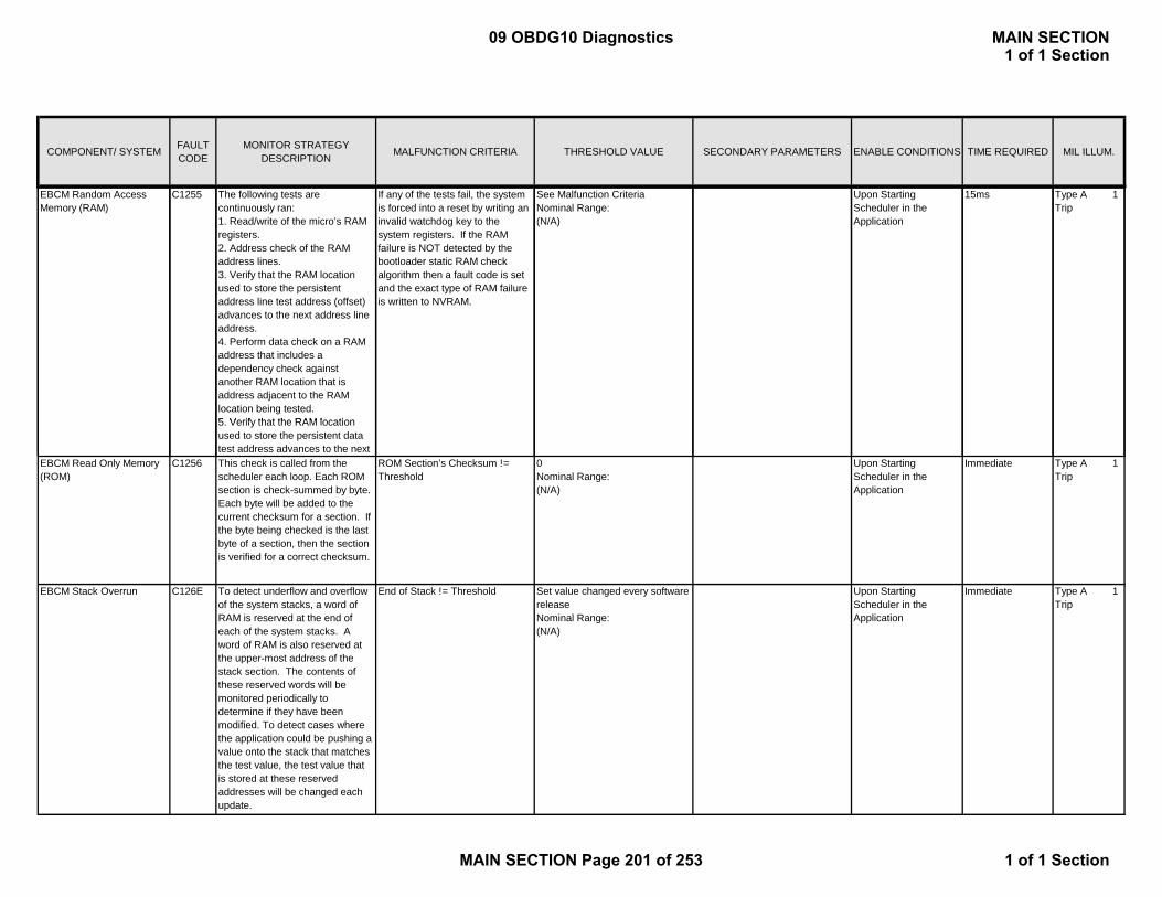
COMPONENT/ SYSTEM FAULT CODE
MONITOR STRATEGY DESCRIPTION MALFUNCTION CRITERIA THRESHOLD VALUE SECONDARY PARAMETERS ENABLE CONDITIONS TIME REQUIRED MIL ILLUM.
EBCM Random Access Memory (RAM)
C1255 The following tests are continuously ran:1. Read/write of the micro’s RAM registers. 2. Address check of the RAM address lines.3. Verify that the RAM location used to store the persistent address line test address (offset) advances to the next address line address.4. Perform data check on a RAM address that includes a dependency check against another RAM location that is address adjacent to the RAM location being tested.5 Verify that the RAM location
If any of the tests fail, the system is forced into a reset by writing an invalid watchdog key to the system registers. If the RAM failure is NOT detected by the bootloader static RAM check algorithm then a fault code is set and the exact type of RAM failure is written to NVRAM.
See Malfunction CriteriaNominal Range:(N/A)
Upon Starting Scheduler in the Application
15ms Type A 1 Trip
5. Verify that the RAM location used to store the persistent data test address advances to the next
EBCM Read Only Memory (ROM)
C1256 This check is called from the scheduler each loop. Each ROM section is check-summed by byte. Each byte will be added to the current checksum for a section. If the byte being checked is the last byte of a section, then the section is verified for a correct checksum.
ROM Section’s Checksum != Threshold
0Nominal Range:(N/A)
Upon Starting Scheduler in the Application
Immediate Type A 1 Trip
EBCM Stack Overrun C126E To detect underflow and overflow of the system stacks, a word of RAM is reserved at the end of each of the system stacks. A word of RAM is also reserved at the upper-most address of the stack section. The contents of these reserved words will be monitored periodically to determine if they have been modified. To detect cases where the application could be pushing a value onto the stack that matches the test value, the test value that is stored at these reserved addresses will be changed each update.
End of Stack != Threshold Set value changed every software releaseNominal Range:(N/A)
Upon Starting Scheduler in the Application
Immediate Type A 1 Trip
09 OBDG10 Diagnostics MAIN SECTION1 of 1 Section
MAIN SECTION Page 201 of 253 1 of 1 Section

COMPONENT/ SYSTEM FAULT CODE
MONITOR STRATEGY DESCRIPTION MALFUNCTION CRITERIA THRESHOLD VALUE SECONDARY PARAMETERS ENABLE CONDITIONS TIME REQUIRED MIL ILLUM.
EBCM Processor Overrun C121D Processor did not perform a proper shutdown. NVRAM blocks written at shutdown do not match expected values upon startup. Processing interrupt occurred.
The contents of the two NVRAM blocks are compared upon start-up with expected values from shutdown process.
Blocks do not compare Upon Starting Scheduler in the Application
15ms Type A 1 Trip
EBCM Unimplemented Interrupt
C121E This fault is set if an interrupt occurs that has no explicit interrupt handler defined.
Interrupt Set = Threshold Not Defined Interrupt HandlerNominal Range:(N/A)
Upon Starting Scheduler in the Application
15ms Type A 1 Trip
EBCM Unexpected Exception
C121F This fault is set if an exception that is not supported in our system has been generated.
Exception Not Supported = Condition
N/ANominal Range:(N/A)
Upon Starting Scheduler in the Application
15ms Type A 1 Trip
EBCM A/D Conversion Timeout
C127D If the Analog to digital converter does not complete its conversion in a set amount of time then this fault is set.
A/D Conversion Counter = Threshold
0 (Counts down from 100)Nominal Range:(N/A)
Upon Starting Scheduler in the Application
100 clock cycles Type A 1 Trip
EBCM Non-Volatile Random Access Memory
C12FF Checksum Error Fault NVRAM status bit sent out by core software reports a failed
NVRAMDiagstat > 0Fault Counts > 0
Upon Starting Scheduler in the
15ms Type B 2 Trips
(NVRAM) / Non-volatile RAM
NVRAM Nominal Range:(N/A)
Application
EBCM Non-Volatile Random Access Memory (NVRAM) / Software Learn ID
C12FF Software ID held in NVRAM does not match ID hard coded in software
BB NVRAM SW BLOCK ID ~=Software ID
SwVerIDStat > 0Nominal Range:(N/A)
Upon Starting Scheduler in the Application
15ms Type B 2 Trips
EBCM High End Timer Performance
C127A Execution of the High End Timer (HET) program is limited to the actual instructions of the HET program. Execution of default instructions indicates program execution error.
Default Instructions = Threshold ExecutedNominal Range:(N/A)
Upon Starting Scheduler in the Application
15ms Type A 1 Trip
EBCM High End Timer Program Overflow
C123B If the HET program does not complete execution time within one HET loop time, the current HET program is aborted and the next program execution is started and a fault code is set.
HET Program Exectution Time > Threshold
HET Loop TimeNominal Range:(N/A)
Upon Starting Scheduler in the Application
15ms Type A 1 Trip
09 OBDG10 Diagnostics MAIN SECTION1 of 1 Section
MAIN SECTION Page 202 of 253 1 of 1 Section
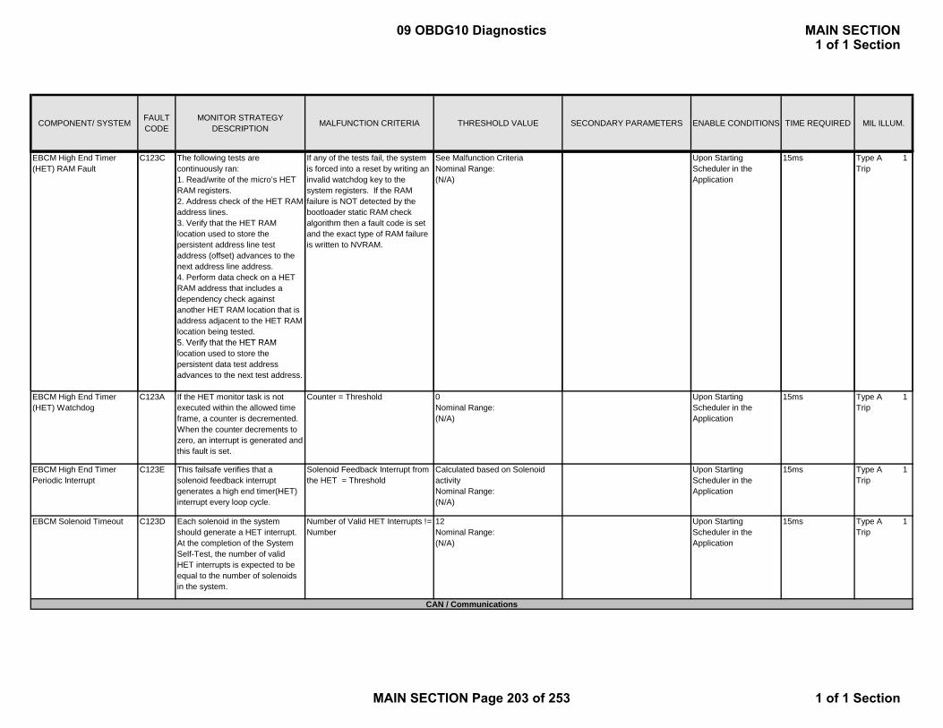
COMPONENT/ SYSTEM FAULT CODE
MONITOR STRATEGY DESCRIPTION MALFUNCTION CRITERIA THRESHOLD VALUE SECONDARY PARAMETERS ENABLE CONDITIONS TIME REQUIRED MIL ILLUM.
EBCM High End Timer (HET) RAM Fault
C123C The following tests are continuously ran:1. Read/write of the micro’s HET RAM registers. 2. Address check of the HET RAM address lines.3. Verify that the HET RAM location used to store the persistent address line test address (offset) advances to the next address line address.4. Perform data check on a HET RAM address that includes a dependency check against another HET RAM location that is address adjacent to the HET RAM location being tested.5 Verify that the HET RAM
If any of the tests fail, the system is forced into a reset by writing an invalid watchdog key to the system registers. If the RAM failure is NOT detected by the bootloader static RAM check algorithm then a fault code is set and the exact type of RAM failure is written to NVRAM.
See Malfunction CriteriaNominal Range:(N/A)
Upon Starting Scheduler in the Application
15ms Type A 1 Trip
5. Verify that the HET RAM location used to store the persistent data test address advances to the next test address.
EBCM High End Timer (HET) Watchdog
C123A If the HET monitor task is not executed within the allowed time frame, a counter is decremented. When the counter decrements to zero, an interrupt is generated and this fault is set.
Counter = Threshold 0Nominal Range:(N/A)
Upon Starting Scheduler in the Application
15ms Type A 1 Trip
EBCM High End Timer Periodic Interrupt
C123E This failsafe verifies that a solenoid feedback interrupt generates a high end timer(HET) interrupt every loop cycle.
Solenoid Feedback Interrupt from the HET = Threshold
Calculated based on Solenoid activityNominal Range:(N/A)
Upon Starting Scheduler in the Application
15ms Type A 1 Trip
EBCM Solenoid Timeout C123D Each solenoid in the system should generate a HET interrupt. At the completion of the System Self-Test, the number of valid HET interrupts is expected to be equal to the number of solenoids in the system.
Number of Valid HET Interrupts != Number
12Nominal Range:(N/A)
Upon Starting Scheduler in the Application
15ms Type A 1 Trip
CAN / Communications
09 OBDG10 Diagnostics MAIN SECTION1 of 1 Section
MAIN SECTION Page 203 of 253 1 of 1 Section
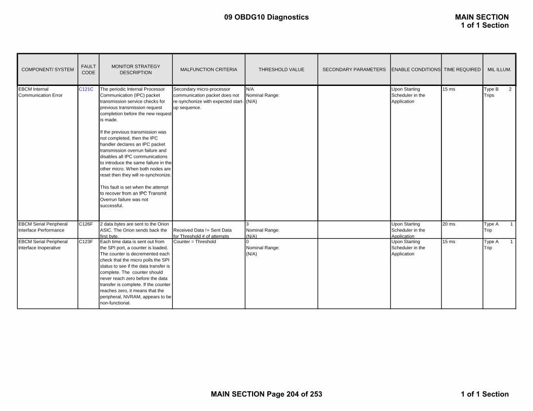
COMPONENT/ SYSTEM FAULT CODE
MONITOR STRATEGY DESCRIPTION MALFUNCTION CRITERIA THRESHOLD VALUE SECONDARY PARAMETERS ENABLE CONDITIONS TIME REQUIRED MIL ILLUM.
EBCM Internal Communication Error
C121C The periodic Internal Processor Communication (IPC) packet transmission service checks for previous transmission request completion before the new request is made.
If the previous transmission was not completed, then the IPC handler declares an IPC packet transmission overrun failure and disables all IPC communications to introduce the same failure in the other micro. When both nodes are reset then they will re-synchronize.
This fault is set when the attempt to recover from an IPC Transmit
Secondary micro-processor communication packet does not re-synchonize with expected start-up sequence.
N/ANominal Range:(N/A)
Upon Starting Scheduler in the Application
15 ms Type B 2 Trips
to recover from an IPC Transmit Overrun failure was not successful.
EBCM Serial Peripheral Interface Performance
C126F 2 data bytes are sent to the Orion ASIC. The Orion sends back the first byte.
Received Data != Sent Data for Threshold # of attempts
3Nominal Range:(N/A)
Upon Starting Scheduler in the Application
20 ms Type A 1 Trip
EBCM Serial Peripheral Interface Inoperative
C123F Each time data is sent out from the SPI port, a counter is loaded. The counter is decremented each check that the micro polls the SPI status to see if the data transfer is complete. The counter should never reach zero before the data transfer is complete. If the counter reaches zero, it means that the peripheral, NVRAM, appears to be non-functional.
Counter = Threshold 0Nominal Range:(N/A)
Upon Starting Scheduler in the Application
15 ms Type A 1 Trip
09 OBDG10 Diagnostics MAIN SECTION1 of 1 Section
MAIN SECTION Page 204 of 253 1 of 1 Section
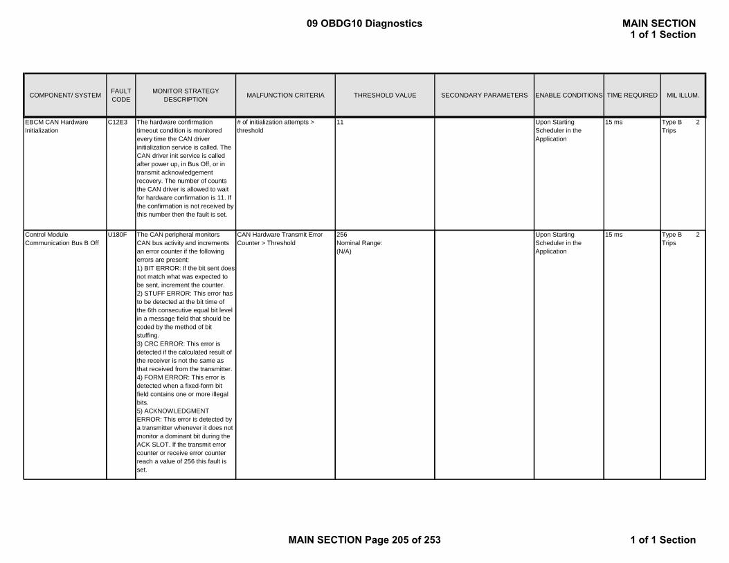
COMPONENT/ SYSTEM FAULT CODE
MONITOR STRATEGY DESCRIPTION MALFUNCTION CRITERIA THRESHOLD VALUE SECONDARY PARAMETERS ENABLE CONDITIONS TIME REQUIRED MIL ILLUM.
EBCM CAN Hardware Initialization
C12E3 The hardware confirmation timeout condition is monitored every time the CAN driver initialization service is called. The CAN driver init service is called after power up, in Bus Off, or in transmit acknowledgement recovery. The number of counts the CAN driver is allowed to wait for hardware confirmation is 11. If the confirmation is not received by this number then the fault is set.
# of initialization attempts > threshold
11 Upon Starting Scheduler in the Application
15 ms Type B 2 Trips
Control Module Communication Bus B Off
U180F The CAN peripheral monitors CAN bus activity and increments an error counter if the following errors are present:
CAN Hardware Transmit Error Counter > Threshold
256Nominal Range:(N/A)
Upon Starting Scheduler in the Application
15 ms Type B 2 Trips
p1) BIT ERROR: If the bit sent does not match what was expected to be sent, increment the counter.2) STUFF ERROR: This error has to be detected at the bit time of the 6th consecutive equal bit level in a message field that should be coded by the method of bit stuffing.3) CRC ERROR: This error is detected if the calculated result of the receiver is not the same as that received from the transmitter.4) FORM ERROR: This error is detected when a fixed-form bit field contains one or more illegal bits. 5) ACKNOWLEDGMENT ERROR: This error is detected by a transmitter whenever it does not monitor a dominant bit during the ACK SLOT. If the transmit error counter or receive error counter reach a value of 256 this fault is set.
09 OBDG10 Diagnostics MAIN SECTION1 of 1 Section
MAIN SECTION Page 205 of 253 1 of 1 Section

COMPONENT/ SYSTEM FAULT CODE
MONITOR STRATEGY DESCRIPTION MALFUNCTION CRITERIA THRESHOLD VALUE SECONDARY PARAMETERS ENABLE CONDITIONS TIME REQUIRED MIL ILLUM.
EBCM Communication Bus "B" RAM Error
C126D The first CAN device does not pass RAM check on the mailbox area. The CAN mailbox RAM check is executed once after power up or reset of the microprocessor.
RAM Read value != RAM Written value
0Nominal Range:(N/A)
Executed once upon startup
15 ms Two Trips Type B
EBCM Communication Bus "B" Performance
C126C The CAN frame does not receive acknowledgement for predefined amount of time. If this fault is enabled in the node supervisor then transmit confirmation is expected within 200 ms.Transmit request sets the timeout timer and successful transmission resets the timeout timer.
CAN Frame acknowledgement not received
Not ReceivedNominal Range: (N/A)
Upon Starting Scheduler in the Application
200ms Type B 2 Trips
Antilock Brake System Control Module Lost
U1843 One or more of the Communication messages (3)
The specified input packet with consistent data was not received
Nominal Range: (N/A) Upon Starting Scheduler in the
2.5 times the expected message
Type B 2 TripsControl Module Lost
Communication With Hybrid Powertrain Control Module on Bus B
Communication messages (3) with the Hybrid Powertrain Control Module are missing.
consistent data was not received by COMMS for a predefined time. Every periodic input packet is monitored for input deadline timeout. The deadline timeout is reset each time new packet data is received. The deadline timeout is either set in DBC file or during the configuration of the COMMS subsystem.
Scheduler in the Application
expected message transmit time
Trips
Antilock Brake System Control Module Lost Communication With Engine Control Module on Bus B
U1842 Communication message with the Engine Control Module is missing.
The specified input packet with consistent data was not received by COMMS for a predefined time. Every periodic input packet is monitored for input deadline timeout. The deadline timeout is reset each time new packet data is received. The deadline timeout is either set in DBC file or during the configuration of the COMMS subsystem.
Upon Starting Scheduler in the Application
2.5 times the expected message transmit time
Type B 2 Trips
09 OBDG10 Diagnostics MAIN SECTION1 of 1 Section
MAIN SECTION Page 206 of 253 1 of 1 Section
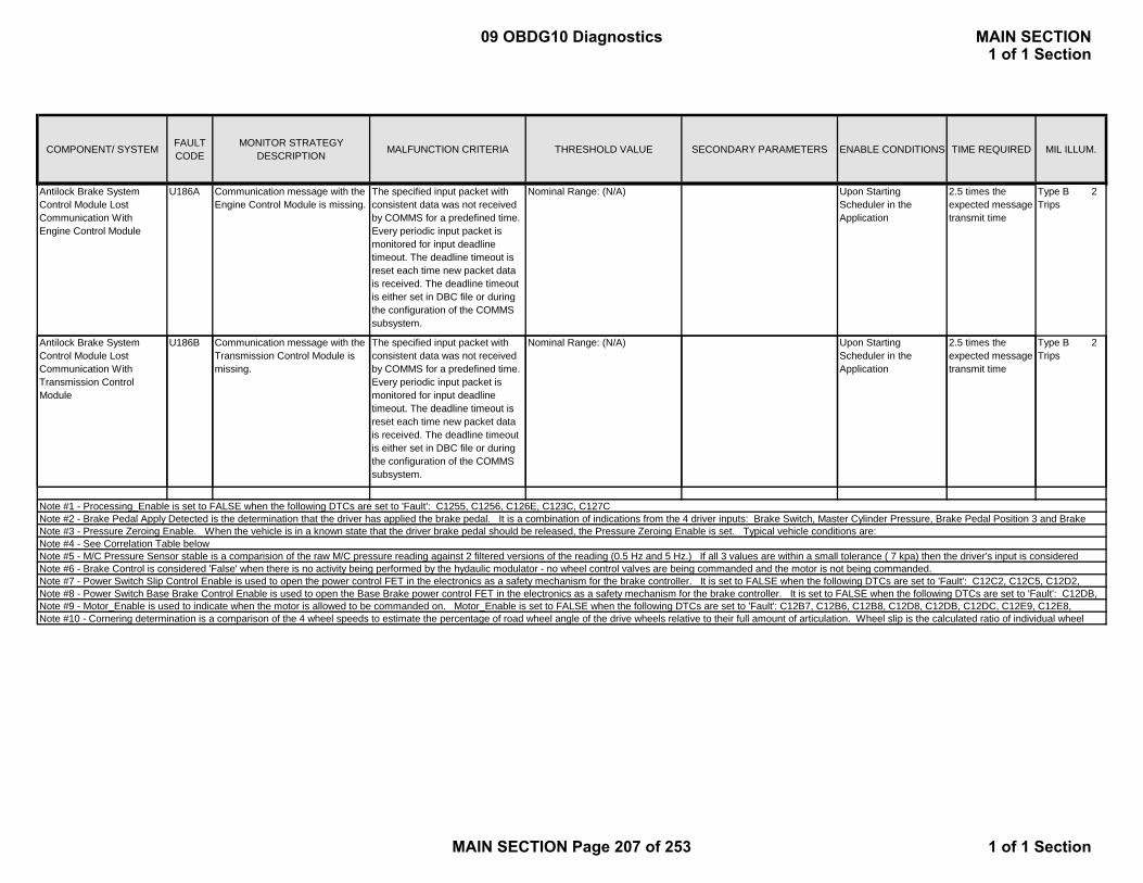
COMPONENT/ SYSTEM FAULT CODE
MONITOR STRATEGY DESCRIPTION MALFUNCTION CRITERIA THRESHOLD VALUE SECONDARY PARAMETERS ENABLE CONDITIONS TIME REQUIRED MIL ILLUM.
Antilock Brake System Control Module Lost Communication With Engine Control Module
U186A Communication message with the Engine Control Module is missing.
The specified input packet with consistent data was not received by COMMS for a predefined time. Every periodic input packet is monitored for input deadline timeout. The deadline timeout is reset each time new packet data is received. The deadline timeout is either set in DBC file or during the configuration of the COMMS subsystem.
Nominal Range: (N/A) Upon Starting Scheduler in the Application
2.5 times the expected message transmit time
Type B 2 Trips
Antilock Brake System Control Module Lost Communication With Transmission Control Module
U186B Communication message with the Transmission Control Module is missing.
The specified input packet with consistent data was not received by COMMS for a predefined time. Every periodic input packet is monitored for input deadline timeout. The deadline timeout is
Nominal Range: (N/A) Upon Starting Scheduler in the Application
2.5 times the expected message transmit time
Type B 2 Trips
timeout. The deadline timeout is reset each time new packet data is received. The deadline timeout is either set in DBC file or during the configuration of the COMMS subsystem.
Note #2 - Brake Pedal Apply Detected is the determination that the driver has applied the brake pedal. It is a combination of indications from the 4 driver inputs: Brake Switch, Master Cylinder Pressure, Brake Pedal Position 3 and Brake Note #1 - Processing_Enable is set to FALSE when the following DTCs are set to 'Fault': C1255, C1256, C126E, C123C, C127C
Note #9 - Motor_Enable is used to indicate when the motor is allowed to be commanded on. Motor_Enable is set to FALSE when the following DTCs are set to 'Fault': C12B7, C12B6, C12B8, C12D8, C12DB, C12DC, C12E9, C12E8, Note #10 - Cornering determination is a comparison of the 4 wheel speeds to estimate the percentage of road wheel angle of the drive wheels relative to their full amount of articulation. Wheel slip is the calculated ratio of individual wheel
Note #5 - M/C Pressure Sensor stable is a comparision of the raw M/C pressure reading against 2 filtered versions of the reading (0.5 Hz and 5 Hz.) If all 3 values are within a small tolerance ( 7 kpa) then the driver's input is considered Note #6 - Brake Control is considered 'False' when there is no activity being performed by the hydaulic modulator - no wheel control valves are being commanded and the motor is not being commanded.Note #7 - Power Switch Slip Control Enable is used to open the power control FET in the electronics as a safety mechanism for the brake controller. It is set to FALSE when the following DTCs are set to 'Fault': C12C2, C12C5, C12D2, Note #8 - Power Switch Base Brake Control Enable is used to open the Base Brake power control FET in the electronics as a safety mechanism for the brake controller. It is set to FALSE when the following DTCs are set to 'Fault': C12DB,
Note #3 - Pressure Zeroing Enable. When the vehicle is in a known state that the driver brake pedal should be released, the Pressure Zeroing Enable is set. Typical vehicle conditions are:Note #4 - See Correlation Table below
09 OBDG10 Diagnostics MAIN SECTION1 of 1 Section
MAIN SECTION Page 207 of 253 1 of 1 Section

3500
4500
Note 4: Correlation Table
In this region –set
-500
500
1500
2500
3500
4500
0 5 10 15 20 25 30
Pres
sure
(kPa
)
Travel(mm at Rod)
Note 4: Correlation Table
Max pressMin press
In this region –set C12B1
In this region – set C12F8
09 OBDG10 Diagnostics MAIN SECTION1 of 1 Section
MAIN SECTION Page 208 of 253 1 of 1 Section

COMPONENT/ SYSTEM FAULT CODE
MONITOR STRATEGY DESCRIPTION MALFUNCTION CRITERIA THRESHOLD VALUE SECONDARY PARAMETERS ENABLE CONDITIONS TIME REQUIRED MIL ILLUM.
HS Comm Enable input = TRUEBPCM Power Mode =RUNHS Comm Enable input = TRUE Type B 2
TripsBPCM Power Mode =RUNHS Comm Enable input = TRUEBPCM Power Mode =RUN
Block 1 < 2 V 12V System Voltage >= 9.0 V<= 18.0 V
1.5 seconds
No active DTCs: P0A1FBPCM Power Mode =RUN (15 fail/20 sample;
100 ms frequency)
Block 1 > 23 V 12V System Voltage >= 9.0 V<= 18.0 V
1.5 seconds
No active DTCs: P0A1F (15 fail/20 sample; 100 ms frequency)
BPCM Power Mode =RUN| Block 1 * 20 - Battery Pack Voltage|
> 70 V 12V System Voltage >= 9.0 V<= 18.0 V
16 seconds
Block 1 Voltage sensor input = VALID (160 fail/170 sample; 100 ms frequency)
No active DTCs: P0A1FP0B3DP0B3EP0ABCP0ABDP0ABB
BPCM Power Mode =RUNTime since contactors closed > 100ms
Block 2 < 2 V 12V System Voltage >= 9.0 V<= 18.0 V
1.5 seconds
AND No active DTCs: P0A1FBlock 3 < 2 V BPCM Power Mode =RUN (15 fail/20 sample;
100 ms frequency)
Block 2 > 23 V 12V System Voltage >= 9.0 V<= 18.0 V
1.5 seconds
No active DTCs: P0A1F (15 fail/20 sample; 100 ms frequency)
BPCM Power Mode =RUN| Block 2 * 20 - Battery Pack Voltage|
> 70 V 12V System Voltage >= 9.0 V<= 18.0 V
16 seconds
3.0 s
> 3.0 s 3.0 s Type B 2 Trips
> 3.0 s
Block 2 Voltage measurement – Out of Range - High
Block 1 Voltage measurement – Out of Range - High
P0B3E
CAN Communication:
Block 1 Voltage Sensor Circuit:
Out of range high
Block 1 Voltage measurement – Rationality
Rationality compares block voltage sensor to pack voltage sensor
P0B41 Rationality compares block voltage sensor to pack voltage
Block 2 Voltage measurement – Out of Range - Low
P0B42 Out of range low Type B 2 Trips
Block 2 Voltage measurement – Rationality
Communication Error
Out of range high
Type B 2 Trips
Type B 2 Trips
Type B 2 Trips
Type B 2 Trips
75ms
CAN Communication Loss – HCP
U1885 Communication Error No message from HCP (Contactor Command)
CAN Communication Loss – ECM
U1886
CAN Communication Loss – CGM
U1862
No message from ECM (Vehicle Speed Average)
Special Type "C"
> 75ms
Block 1 Voltage measurement – Out of Range - Low
P0B3D Out of range low
No message from CGM (Fan Speed Limit)
Communication Error
Type B 2 Trips
P0B43
P0B3C
Block 2 Voltage Sensor Circuit:
09 OBDG10 Diagnostics MAIN SECTION1 of 1 Section
MAIN SECTION Page 209 of 253 1 of 1 Section

COMPONENT/ SYSTEM FAULT CODE
MONITOR STRATEGY DESCRIPTION MALFUNCTION CRITERIA THRESHOLD VALUE SECONDARY PARAMETERS ENABLE CONDITIONS TIME REQUIRED MIL ILLUM.
AND Block 2 Voltage sensor input = VALID (160 fail/170 sample; 100 ms frequency)
| Block 3 * 20 - Battery Pack Voltage|
> 70 V No active DTCs: P0A1F
P0B42P0B43P0ABCP0ABDP0ABB
BPCM Power Mode =RUNTime since contactors closed > 100ms
Block 3 < 2 V 12V System Voltage >= 9.0 V<= 18.0 V
1.5 seconds
AND No active DTCs: P0A1FBlock 4 < 2 V BPCM Power Mode =RUN (15 fail/20 sample;
100 ms frequency)
Block 3 > 23 V 12V System Voltage >= 9.0 V<= 18.0 V
1.5 seconds
No active DTCs: P0A1F (15 fail/20 sample; 100 ms frequency)
BPCM Power Mode =RUN| Block 3 * 20 - Battery Pack Voltage|
> 70 V 12V System Voltage >= 9.0 V<= 18.0 V
16 seconds
AND Block 3 Voltage sensor input = VALID (160 fail/170 sample; 100 ms frequency)
| Block 4 * 20 - Battery Pack Voltage|
> 70 V No active DTCs: P0A1F
P0B47P0B48P0ABCP0ABDP0ABB
BPCM Power Mode =RUNTime since contactors closed > 100ms
Block 4 < 2 V 12V System Voltage >= 9.0 V<= 18.0 V
1.5 seconds
AND No active DTCs: P0A1FBlock 5 < 2 V BPCM Power Mode =RUN (15 fail/20 sample;
100 ms frequency)
Block 4 > 23 V 12V System Voltage >= 9.0 V<= 18.0 V
1.5 seconds
Type B 2 Trips
Type B 2 Trips
Block 3 Voltage measurement – Rationality
Rationality compares block voltage sensor to pack voltage sensor
Block 4 Voltage measurement – Out of Range - Low
Out of range lowBlock 4 Voltage Sensor Circuit:
sensor
Block 3 Voltage measurement – Out of Range - Low
Out of range low
Block 4 Voltage measurement – Out of
Out of range high Type B 2 Trips
Type B 2 Trips
Block 3 Voltage measurement – Out of Range - High
Out of range high
Type B 2 Trips
P0B47
P0B48
P0B46
P0B4C
P0B4D
Block 3 Voltage Sensor Circuit:
09 OBDG10 Diagnostics MAIN SECTION1 of 1 Section
MAIN SECTION Page 210 of 253 1 of 1 Section

COMPONENT/ SYSTEM FAULT CODE
MONITOR STRATEGY DESCRIPTION MALFUNCTION CRITERIA THRESHOLD VALUE SECONDARY PARAMETERS ENABLE CONDITIONS TIME REQUIRED MIL ILLUM.
No active DTCs: P0A1F (15 fail/20 sample; 100 ms frequency)
BPCM Power Mode =RUN| Block 4 * 20 - Battery Pack Voltage|
> 70 V 12V System Voltage >= 9.0 V<= 18.0 V
16 seconds
AND Block 4 Voltage sensor input = VALID (160 fail/170 sample; 100 ms frequency)
| Block 5 * 20 - Battery Pack Voltage|
> 70 V No active DTCs: P0A1F
P0B4CP0B4DP0ABCP0ABDP0ABB
BPCM Power Mode =RUNTime since contactors closed > 100ms
Block 5 < 2 V 12V System Voltage >= 9.0 V<= 18.0 V
1.5 seconds
AND No active DTCs: P0A1FBlock 6 < 2 V BPCM Power Mode =RUN (15 fail/20 sample;
100 ms frequency)
Block 5 > 23 V 12V System Voltage >= 9.0 V<= 18.0 V
1.5 seconds
No active DTCs: P0A1F (15 fail/20 sample; 100 ms frequency)
BPCM Power Mode =RUN| Block 5 * 20 - Battery Pack Voltage|
> 70 V 12V System Voltage >= 9.0 V<= 18.0 V
16 seconds
AND Block 5 Voltage sensor input = VALID (160 fail/170 sample; 100 ms frequency)
| Block 6 * 20 - Battery Pack Voltage|
> 70 V No active DTCs: P0A1F
P0B51P0B52P0ABCP0ABDP0ABB
BPCM Power Mode =RUNTime since contactors closed > 100ms
Block 6 < 2 V 12V System Voltage >= 9.0 V<= 18.0 V
1.5 seconds
AND No active DTCs: P0A1F
Type B 2 Trips
P0B56
Type B 2 Trips
Block 5 Voltage measurement – Out of Range - High
Block 6 Voltage measurement - Out of Range - Low
Out of range lowBlock 6 Voltage Sensor Circuit:
Range - High
Type B 2 Trips
Block 5 Voltage measurement – Out of Range - Low
Out of range low Type B 2 Trips
Block 4 Voltage measurement – Rationality
Rationality compares block voltage sensor to pack voltage sensor
Block 5 Voltage Sensor Circuit:
P0B4B
P0B51
Type B 2 Trips
P0B52
P0B50
Out of range high
Block 5 Voltage measurement – Rationality
Rationality compares block voltage sensor to pack voltage sensor
09 OBDG10 Diagnostics MAIN SECTION1 of 1 Section
MAIN SECTION Page 211 of 253 1 of 1 Section

COMPONENT/ SYSTEM FAULT CODE
MONITOR STRATEGY DESCRIPTION MALFUNCTION CRITERIA THRESHOLD VALUE SECONDARY PARAMETERS ENABLE CONDITIONS TIME REQUIRED MIL ILLUM.
Block 7 < 2 V BPCM Power Mode =RUN (15 fail/20 sample; 100 ms frequency)
Block 6 > 23 V 12V System Voltage >= 9.0 V<= 18.0 V
1.5 seconds
No active DTCs: P0A1F (15 fail/20 sample; 100 ms frequency)
BPCM Power Mode =RUN| Block 6 * 20 - Battery Pack Voltage|
> 70 V 12V System Voltage >= 9.0 V<= 18.0 V
16 seconds
AND Block 1 Voltage sensor input = VALID (160 fail/170 sample; 100 ms frequency)
| Block 7 * 20 - Battery Pack Voltage|
> 70 V No active DTCs: P0A1F
P0B56P0B57P0ABCP0ABDP0ABB
BPCM Power Mode =RUNTime since contactors closed > 100ms
Block 7 < 2 V 12V System Voltage >= 9.0 V<= 18.0 V
1.5 seconds
AND No active DTCs: P0A1FBlock 8 < 2 V BPCM Power Mode =RUN (15 fail/20 sample;
100 ms frequency)
Block 7 > 23 V 12V System Voltage >= 9.0 V<= 18.0 V
1.5 seconds
No active DTCs: P0A1F (15 fail/20 sample; 100 ms frequency)
BPCM Power Mode =RUN| Block 7 * 20 - Battery Pack Voltage|
> 70 V 12V System Voltage >= 9.0 V<= 18.0 V
16 seconds
AND Block 7 Voltage sensor input = VALID (160 fail/170 sample; 100 ms frequency)
| Block 8 * 20 - Battery Pack Voltage|
> 70 V No active DTCs: P0A1F
P0B5BP0B5CP0ABCP0ABDP0ABB
BPCM Power Mode =RUNTime since contactors closed > 100ms
Block 7 Voltage Sensor Circuit:
Type B 2 Trips
Type B 2 Trips
Type B 2 Trips
Type B 2 Trips
Type B 2 Trips
Block 7 Voltage measurement - Out of Range - High
Out of range high
Block 7 Voltage measurement - Rationality
Rationality compares block voltage sensor to pack voltage sensor
P0B5C
P0B5A
Block 6 Voltage measurement - Out of Range - High
Out of range highP0B57
Block 7 Voltage measurement - Out of Range - Low
Out of range low
P0B55
P0B5B
g
Block 6 Voltage measurement - Rationality
Rationality compares block voltage sensor to pack voltage sensor
09 OBDG10 Diagnostics MAIN SECTION1 of 1 Section
MAIN SECTION Page 212 of 253 1 of 1 Section
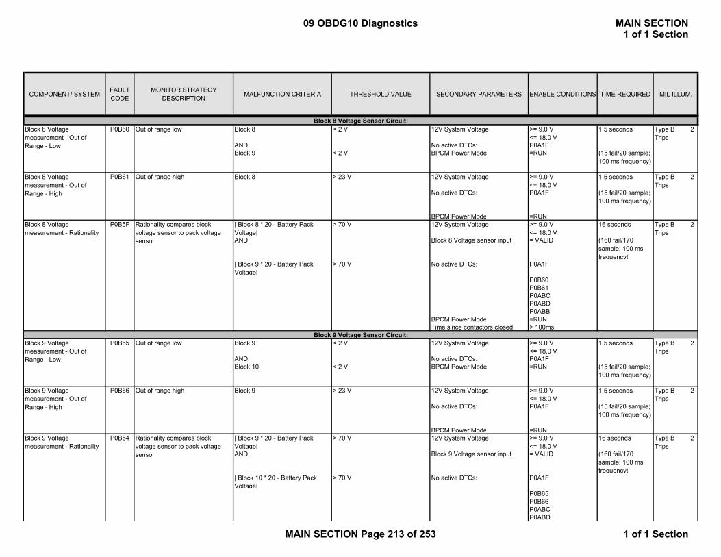
COMPONENT/ SYSTEM FAULT CODE
MONITOR STRATEGY DESCRIPTION MALFUNCTION CRITERIA THRESHOLD VALUE SECONDARY PARAMETERS ENABLE CONDITIONS TIME REQUIRED MIL ILLUM.
Block 8 < 2 V 12V System Voltage >= 9.0 V<= 18.0 V
1.5 seconds
AND No active DTCs: P0A1FBlock 9 < 2 V BPCM Power Mode =RUN (15 fail/20 sample;
100 ms frequency)
Block 8 > 23 V 12V System Voltage >= 9.0 V<= 18.0 V
1.5 seconds
No active DTCs: P0A1F (15 fail/20 sample; 100 ms frequency)
BPCM Power Mode =RUN| Block 8 * 20 - Battery Pack Voltage|
> 70 V 12V System Voltage >= 9.0 V<= 18.0 V
16 seconds
AND Block 8 Voltage sensor input = VALID (160 fail/170 sample; 100 ms frequency)
| Block 9 * 20 - Battery Pack Voltage|
> 70 V No active DTCs: P0A1F
P0B60P0B61P0ABCP0ABDP0ABB
BPCM Power Mode =RUNTime since contactors closed > 100ms
Block 9 < 2 V 12V System Voltage >= 9.0 V<= 18.0 V
1.5 seconds
AND No active DTCs: P0A1FBlock 10 < 2 V BPCM Power Mode =RUN (15 fail/20 sample;
100 ms frequency)
Block 9 > 23 V 12V System Voltage >= 9.0 V<= 18.0 V
1.5 seconds
No active DTCs: P0A1F (15 fail/20 sample; 100 ms frequency)
BPCM Power Mode =RUN| Block 9 * 20 - Battery Pack Voltage|
> 70 V 12V System Voltage >= 9.0 V<= 18.0 V
16 seconds
AND Block 9 Voltage sensor input = VALID (160 fail/170 sample; 100 ms frequency)
| Block 10 * 20 - Battery Pack Voltage|
> 70 V No active DTCs: P0A1F
P0B65P0B66P0ABCP0ABD
Block 8 Voltage measurement - Out of Range - High
P0B60 Type B 2 Trips
Block 8 Voltage measurement - Rationality
Rationality compares block voltage sensor to pack voltage sensor
Out of range low
Type B 2 Trips
Block 9 Voltage Sensor Circuit:
Block 9 Voltage measurement - Out of Range - High
Out of range high Type B 2 Trips
Type B 2 Trips
Block 9 Voltage measurement - Rationality
Rationality compares block voltage sensor to pack voltage sensor
Block 9 Voltage measurement - Out of Range - Low
Out of range low
Block 8 Voltage Sensor Circuit:Block 8 Voltage measurement - Out of Range - Low
Type B 2 Trips
Type B 2 Trips
Out of range highP0B61
P0B5F
P0B65
P0B66
P0B64
09 OBDG10 Diagnostics MAIN SECTION1 of 1 Section
MAIN SECTION Page 213 of 253 1 of 1 Section

COMPONENT/ SYSTEM FAULT CODE
MONITOR STRATEGY DESCRIPTION MALFUNCTION CRITERIA THRESHOLD VALUE SECONDARY PARAMETERS ENABLE CONDITIONS TIME REQUIRED MIL ILLUM.
P0ABBBPCM Power Mode =RUNTime since contactors closed > 100ms
Block 10 < 2 V 12V System Voltage >= 9.0 V<= 18.0 V
1.5 seconds
AND No active DTCs: P0A1FBlock 11 < 2 V BPCM Power Mode =RUN (15 fail/20 sample;
100 ms frequency)
Block 10 > 23 V 12V System Voltage >= 9.0 V<= 18.0 V
1.5 seconds
No active DTCs: P0A1F (15 fail/20 sample; 100 ms frequency)
BPCM Power Mode =RUN| Block 10 * 20 - Battery Pack Voltage|
> 70 V 12V System Voltage >= 9.0 V<= 18.0 V
16 seconds
AND Block 10 Voltage sensor input = VALID (160 fail/170 sample; 100 ms frequency)
| Block 11 * 20 - Battery Pack Voltage|
> 70 V No active DTCs: P0A1F
P0B6AP0B6BP0ABCP0ABDP0ABB
BPCM Power Mode =RUNTime since contactors closed > 100ms
Block 11 < 2 V 12V System Voltage >= 9.0 V<= 18.0 V
1.5 seconds
AND No active DTCs: P0A1FBlock 12 < 2 V BPCM Power Mode =RUN (15 fail/20 sample;
100 ms frequency)
Block 11 > 23 V 12V System Voltage >= 9.0 V<= 18.0 V
1.5 seconds
No active DTCs: P0A1F (15 fail/20 sample; 100 ms frequency)
BPCM Power Mode =RUN| Block 11 * 20 - Battery Pack Voltage|
> 70 V 12V System Voltage >= 9.0 V<= 18.0 V
16 seconds
AND Block 11 Voltage sensor input = VALID (160 fail/170 sample; 100 ms frequency)
| Block 12 * 20 - Battery Pack Voltage|
> 70 V No active DTCs: P0A1F
P0B6F
Block 10 Voltage Sensor Circuit:
Block 11 Voltage Sensor Circuit:
P0B70
P0B6E
Out of range low
P0B69
P0B6F
Block 10 Voltage measurement - Rationality
Rationality compares block voltage sensor to pack voltage sensor
Block 11 Voltage measurement - Out of Range - High
Out of range high
Block 11 Voltage measurement - Rationality
Rationality compares block voltage sensor to pack voltage sensor
Out of range high
Type B 2 Trips
Type B 2 Trips
Type B 2 Trips
Type B 2 Trips
Block 10 Voltage measurement - Out of Range - Low
Out of range low
Block 10 Voltage measurement - Out of Range - High
Block 11 Voltage measurement - Out of Range - Low
Type B 2 Trips
Type B 2 Trips
P0B6A
P0B6B
09 OBDG10 Diagnostics MAIN SECTION1 of 1 Section
MAIN SECTION Page 214 of 253 1 of 1 Section
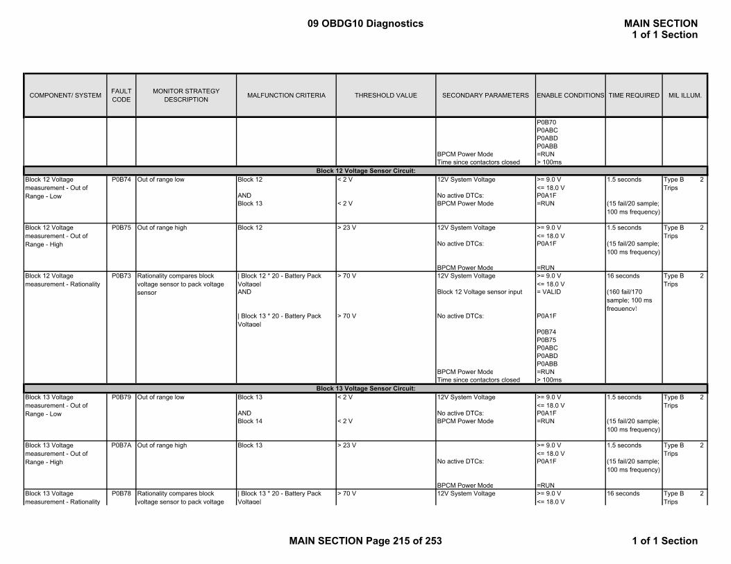
COMPONENT/ SYSTEM FAULT CODE
MONITOR STRATEGY DESCRIPTION MALFUNCTION CRITERIA THRESHOLD VALUE SECONDARY PARAMETERS ENABLE CONDITIONS TIME REQUIRED MIL ILLUM.
P0B70P0ABCP0ABDP0ABB
BPCM Power Mode =RUNTime since contactors closed > 100ms
Block 12 < 2 V 12V System Voltage >= 9.0 V<= 18.0 V
1.5 seconds
AND No active DTCs: P0A1FBlock 13 < 2 V BPCM Power Mode =RUN (15 fail/20 sample;
100 ms frequency)
Block 12 > 23 V 12V System Voltage >= 9.0 V<= 18.0 V
1.5 seconds
No active DTCs: P0A1F (15 fail/20 sample; 100 ms frequency)
BPCM Power Mode =RUN| Block 12 * 20 - Battery Pack Voltage|
> 70 V 12V System Voltage >= 9.0 V<= 18.0 V
16 seconds
AND Block 12 Voltage sensor input = VALID (160 fail/170 sample; 100 ms frequency)
| Block 13 * 20 - Battery Pack Voltage|
> 70 V No active DTCs: P0A1F
P0B74P0B75P0ABCP0ABDP0ABB
BPCM Power Mode =RUNTime since contactors closed > 100ms
Block 13 < 2 V 12V System Voltage >= 9.0 V<= 18.0 V
1.5 seconds
AND No active DTCs: P0A1FBlock 14 < 2 V BPCM Power Mode =RUN (15 fail/20 sample;
100 ms frequency)
Block 13 > 23 V >= 9.0 V<= 18.0 V
1.5 seconds
No active DTCs: P0A1F (15 fail/20 sample; 100 ms frequency)
BPCM Power Mode =RUN| Block 13 * 20 - Battery Pack Voltage|
> 70 V 12V System Voltage >= 9.0 V<= 18.0 V
16 seconds
Rationality compares block voltage sensor to pack voltage sensor
Block 13 Voltage measurement - Out of Range - High
Out of range high
Block 13 Voltage measurement - Rationality
Rationality compares block voltage sensor to pack voltage
P0B7A
P0B78
Block 13 Voltage measurement - Out of Range - Low
Out of range lowP0B79
P0B73
Block 13 Voltage Sensor Circuit:
Block 12 Voltage measurement - Rationality
Block 12 Voltage Sensor Circuit:
Block 12 Voltage measurement - Out of Range - High
Out of range high
P0B74
P0B75
Block 12 Voltage measurement - Out of Range - Low
Out of range low Type B 2 Trips
Type B 2 Trips
Type B 2 Trips
Type B 2 Trips
Type B 2 Trips
Type B 2 Trips
09 OBDG10 Diagnostics MAIN SECTION1 of 1 Section
MAIN SECTION Page 215 of 253 1 of 1 Section
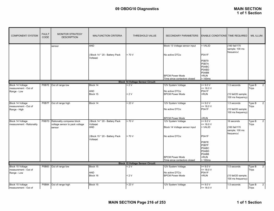
COMPONENT/ SYSTEM FAULT CODE
MONITOR STRATEGY DESCRIPTION MALFUNCTION CRITERIA THRESHOLD VALUE SECONDARY PARAMETERS ENABLE CONDITIONS TIME REQUIRED MIL ILLUM.
AND Block 13 Voltage sensor input = VALID (160 fail/170 sample; 100 ms frequency)
| Block 14 * 20 - Battery Pack Voltage|
> 70 V No active DTCs: P0A1F
P0B79P0B7AP0ABCP0ABDP0ABB
BPCM Power Mode =RUNTime since contactors closed > 100ms
Block 14 < 2 V 12V System Voltage >= 9.0 V<= 18.0 V
1.5 seconds
AND No active DTCs: P0A1FBlock 15 < 2 V BPCM Power Mode =RUN (15 fail/20 sample;
100 ms frequency)
Block 14 > 23 V 12V System Voltage >= 9.0 V<= 18.0 V
1.5 seconds
No active DTCs: P0A1F (15 fail/20 sample; 100 ms frequency)
BPCM Power Mode =RUN| Block 14 * 20 - Battery Pack Voltage|
> 70 V 12V System Voltage >= 9.0 V<= 18.0 V
16 seconds
AND Block 14 Voltage sensor input = VALID (160 fail/170 sample; 100 ms frequency)
| Block 15 * 20 - Battery Pack Voltage|
> 70 V No active DTCs: P0A1F
P0B7EP0B7FP0ABCP0ABDP0ABB
BPCM Power Mode =RUNTime since contactors closed > 100ms
Block 15 < 2 V 12V System Voltage >= 9.0 V<= 18.0 V
1.5 seconds
AND No active DTCs: P0A1FBlock 16 < 2 V BPCM Power Mode =RUN (15 fail/20 sample;
100 ms frequency)
Block 15 > 23 V 12V System Voltage >= 9.0 V<= 18.0 V
1.5 secondsP0B84
Rationality compares block voltage sensor to pack voltage sensor
Block 15 Voltage measurement - Out of Range - Low
Out of range low
P0B7D
P0B83Block 15 Voltage Sensor Circuit:
Block 14 Voltage measurement - Out of Range - Low
Out of range low
Block 14 Voltage measurement - Out of Range - High
Out of range highP0B7F
Block 15 Voltage measurement - Out of
Out of range high
sensor
Block 14 Voltage measurement - Rationality
P0B7EBlock 14 Voltage Sensor Circuit:
Type B 2 Trips
Type B 2 Trips
Type B 2 Trips
Type B 2 Trips
Type B 2 Trips
09 OBDG10 Diagnostics MAIN SECTION1 of 1 Section
MAIN SECTION Page 216 of 253 1 of 1 Section

COMPONENT/ SYSTEM FAULT CODE
MONITOR STRATEGY DESCRIPTION MALFUNCTION CRITERIA THRESHOLD VALUE SECONDARY PARAMETERS ENABLE CONDITIONS TIME REQUIRED MIL ILLUM.
No active DTCs: P0A1F (15 fail/20 sample; 100 ms frequency)
BPCM Power Mode =RUN| Block 15 * 20 - Battery Pack Voltage|
> 70 V 12V System Voltage >= 9.0 V<= 18.0 V
16 seconds
AND Block 15 Voltage sensor input = VALID (160 fail/170 sample; 100 ms frequency)
| Block 16 * 20 - Battery Pack Voltage|
> 70 V No active DTCs: P0A1F
P0B83P0B84P0ABCP0ABDP0ABB
BPCM Power Mode =RUNTime since contactors closed > 100ms
Block 16 < 2 V 12V System Voltage >= 9.0 V<= 18.0 V
1.5 seconds
AND No active DTCs: P0A1FBlock 17 < 2 V BPCM Power Mode =RUN (15 fail/20 sample;
100 ms frequency)
Out of range high Block 16 > 23 V 12V System Voltage >= 9.0 V<= 18.0 V
1.5 seconds
No active DTCs: P0A1F (15 fail/20 sample; 100 ms frequency)
BPCM Power Mode =RUN| Block 16 * 20 - Battery Pack Voltage|
> 70 V 12V System Voltage >= 9.0 V<= 18.0 V
16 seconds
AND Block 16 Voltage sensor input = VALID (160 fail/170 sample; 100 ms frequency)
| Block 17 * 20 - Battery Pack Voltage|
> 70 V No active DTCs: P0A1F
P0B88P0B89P0ABCP0ABDP0ABB
BPCM Power Mode =RUNTime since contactors closed > 100ms
Block 17 < 2 V 12V System Voltage >= 9.0 V<= 18.0 V
1.5 seconds
AND No active DTCs: P0A1F
Rationality compares block voltage sensor to pack voltage sensor
P0B82
Block 16 Voltage measurement - Out of Range - Low
Out of range low
P0B89
P0B87
P0B8DBlock 17 Voltage measurement - Out of Range - Low
Out of range lowBlock 17 Voltage Sensor Circuit:
Rationality compares block voltage sensor to pack voltage sensor
Block 16 Voltage measurement - Out of Range - High
Block 16 Voltage measurement - Rationality
P0B88Block 16 Voltage Sensor Circuit:
Range - High
Block 15 Voltage measurement - Rationality
Type B 2 Trips
Type B 2 Trips
Type B 2 Trips
Type B 2 Trips
Type B 2 Trips
09 OBDG10 Diagnostics MAIN SECTION1 of 1 Section
MAIN SECTION Page 217 of 253 1 of 1 Section

COMPONENT/ SYSTEM FAULT CODE
MONITOR STRATEGY DESCRIPTION MALFUNCTION CRITERIA THRESHOLD VALUE SECONDARY PARAMETERS ENABLE CONDITIONS TIME REQUIRED MIL ILLUM.
Block 18 < 2 V BPCM Power Mode =RUN (15 fail/20 sample; 100 ms frequency)
Block 17 > 23 V 12V System Voltage >= 9.0 V<= 18.0 V
1.5 seconds
No active DTCs: P0A1F (15 fail/20 sample; 100 ms frequency)
BPCM Power Mode =RUN| Block 17 * 20 - Battery Pack Voltage|
> 70 V 12V System Voltage >= 9.0 V<= 18.0 V
16 seconds
AND Block 17 Voltage sensor input = VALID (160 fail/170 sample; 100 ms frequency)
| Block 18 * 20 - Battery Pack Voltage|
> 70 V No active DTCs: P0A1F
P0B8DP0B8EP0ABCP0ABDP0ABB
BPCM Power Mode =RUNTime since contactors closed > 100ms
Block 18 < 2 V 12V System Voltage >= 9.0 V<= 18.0 V
1.5 seconds
AND No active DTCs: P0A1FBlock 19 < 2 V BPCM Power Mode =RUN (15 fail/20 sample;
100 ms frequency)
Block 18 > 23 V 12V System Voltage >= 9.0 V<= 18.0 V
1.5 seconds
No active DTCs: P0A1F (15 fail/20 sample; 100 ms frequency)
BPCM Power Mode =RUN| Block 18 * 20 - Battery Pack Voltage|
> 70 V 12V System Voltage >= 9.0 V<= 18.0 V
16 seconds
AND Block 18 Voltage sensor input = VALID (160 fail/170 sample; 100 ms frequency)
| Block 19 * 20 - Battery Pack Voltage|
> 70 V No active DTCs: P0A1F
P0B92P0B93P0ABCP0ABDP0ABB
BPCM Power Mode =RUNTime since contactors closed > 100ms
P0B93
P0B91 Rationality compares block voltage sensor to pack voltage sensor
Block 18 Voltage measurement - Out of Range - High
Out of range high
Block 18 Voltage measurement - Rationality
Block 18 Voltage measurement - Out of Range - Low
Out of range low
P0B8C
P0B92Block 18 Voltage Sensor Circuit:
Type B 2 Trips
Type B 2 Trips
Block 17 Voltage measurement - Rationality
Rationality compares block voltage sensor to pack voltage sensor
Block 17 Voltage measurement - Out of Range - High
Out of range highP0B8E
g
Type B 2 Trips
Type B 2 Trips
Type B 2 Trips
09 OBDG10 Diagnostics MAIN SECTION1 of 1 Section
MAIN SECTION Page 218 of 253 1 of 1 Section
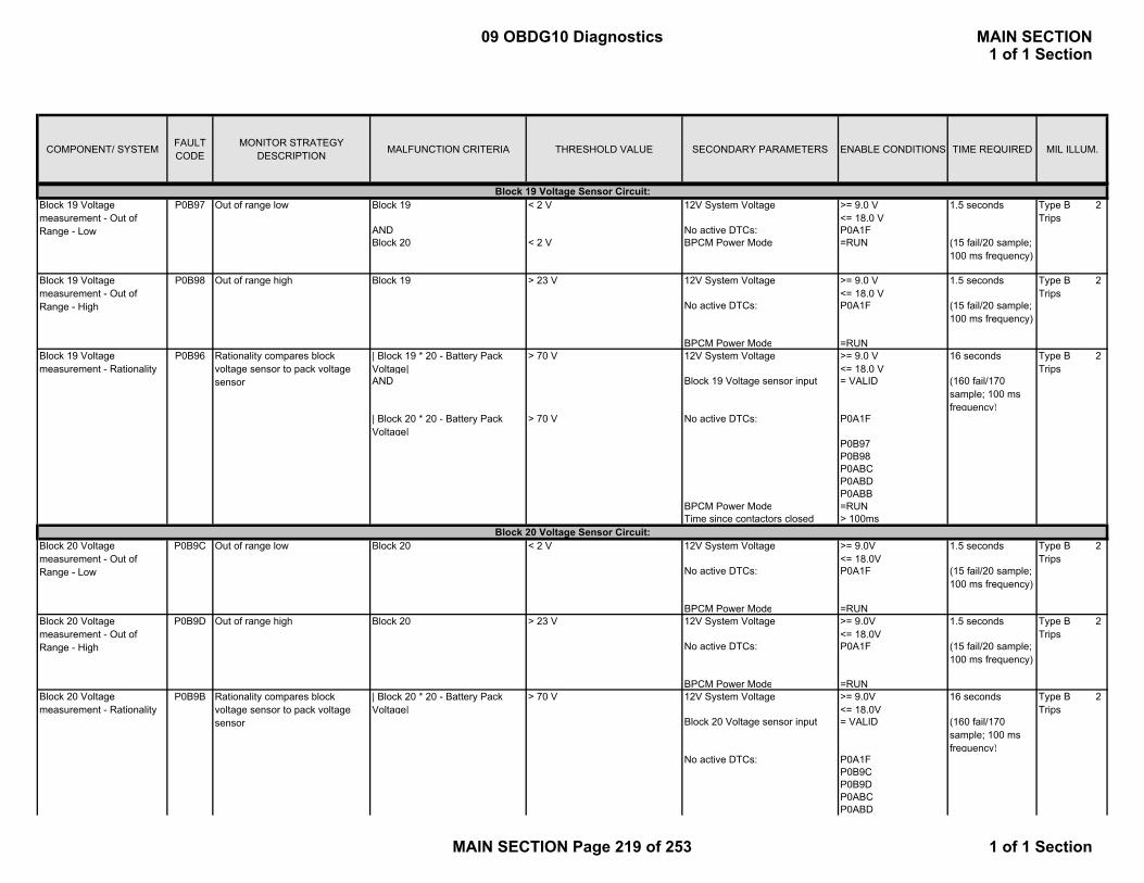
COMPONENT/ SYSTEM FAULT CODE
MONITOR STRATEGY DESCRIPTION MALFUNCTION CRITERIA THRESHOLD VALUE SECONDARY PARAMETERS ENABLE CONDITIONS TIME REQUIRED MIL ILLUM.
Block 19 < 2 V 12V System Voltage >= 9.0 V<= 18.0 V
1.5 seconds
AND No active DTCs: P0A1FBlock 20 < 2 V BPCM Power Mode =RUN (15 fail/20 sample;
100 ms frequency)
Block 19 > 23 V 12V System Voltage >= 9.0 V<= 18.0 V
1.5 seconds
No active DTCs: P0A1F (15 fail/20 sample; 100 ms frequency)
BPCM Power Mode =RUN| Block 19 * 20 - Battery Pack Voltage|
> 70 V 12V System Voltage >= 9.0 V<= 18.0 V
16 seconds
AND Block 19 Voltage sensor input = VALID (160 fail/170 sample; 100 ms frequency)
| Block 20 * 20 - Battery Pack Voltage|
> 70 V No active DTCs: P0A1F
P0B97P0B98P0ABCP0ABDP0ABB
BPCM Power Mode =RUNTime since contactors closed > 100ms
Block 20 < 2 V 12V System Voltage >= 9.0V<= 18.0V
1.5 seconds
No active DTCs: P0A1F (15 fail/20 sample; 100 ms frequency)
BPCM Power Mode =RUNBlock 20 > 23 V 12V System Voltage >= 9.0V
<= 18.0V1.5 seconds
No active DTCs: P0A1F (15 fail/20 sample; 100 ms frequency)
BPCM Power Mode =RUN| Block 20 * 20 - Battery Pack Voltage|
> 70 V 12V System Voltage >= 9.0V<= 18.0V
16 seconds
Block 20 Voltage sensor input = VALID (160 fail/170 sample; 100 ms frequency)
No active DTCs: P0A1FP0B9CP0B9DP0ABCP0ABD
P0B96
P0B9C
P0B9D
P0B9B Rationality compares block voltage sensor to pack voltage sensor
Block 20 Voltage Sensor Circuit:Block 20 Voltage measurement - Out of Range - Low
Out of range low
Block 20 Voltage measurement - Out of Range - High
Block 19 Voltage measurement - Rationality
Rationality compares block voltage sensor to pack voltage sensor
Block 19 Voltage measurement - Out of Range - High
Out of range high
P0B97
P0B98
Block 19 Voltage measurement - Out of Range - Low
Out of range lowBlock 19 Voltage Sensor Circuit:
Type B 2 Trips
Type B 2 Trips
Type B 2 Trips
Out of range high
Block 20 Voltage measurement - Rationality
Type B 2 Trips
Type B 2 Trips
Type B 2 Trips
09 OBDG10 Diagnostics MAIN SECTION1 of 1 Section
MAIN SECTION Page 219 of 253 1 of 1 Section
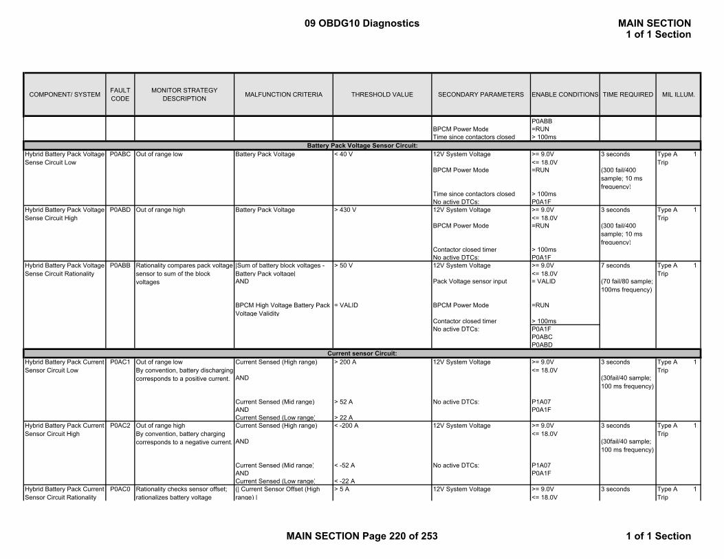
COMPONENT/ SYSTEM FAULT CODE
MONITOR STRATEGY DESCRIPTION MALFUNCTION CRITERIA THRESHOLD VALUE SECONDARY PARAMETERS ENABLE CONDITIONS TIME REQUIRED MIL ILLUM.
P0ABBBPCM Power Mode =RUNTime since contactors closed > 100ms
Battery Pack Voltage < 40 V 12V System Voltage >= 9.0V<= 18.0V
3 seconds
BPCM Power Mode =RUN (300 fail/400 sample; 10 ms frequency)
Time since contactors closed > 100msNo active DTCs: P0A1F
Battery Pack Voltage > 430 V 12V System Voltage >= 9.0V<= 18.0V
3 seconds
BPCM Power Mode =RUN (300 fail/400 sample; 10 ms frequency)
Contactor closed timer > 100msNo active DTCs: P0A1F
|Sum of battery block voltages - Battery Pack voltage|
> 50 V 12V System Voltage >= 9.0V<= 18.0V
7 seconds
AND Pack Voltage sensor input = VALID (70 fail/80 sample; 100ms frequency)
BPCM High Voltage Battery Pack Voltage Validity
= VALID BPCM Power Mode =RUN
Contactor closed timer > 100msNo active DTCs: P0A1F
P0ABCP0ABD
Current Sensed (High range) > 200 A 12V System Voltage >= 9.0V<= 18.0V
3 seconds
AND (30fail/40 sample; 100 ms frequency)
Current Sensed (Mid range) > 52 A No active DTCs: P1A07AND P0A1FCurrent Sensed (Low range) > 22 ACurrent Sensed (High range) < -200 A 12V System Voltage >= 9.0V
<= 18.0V3 seconds
AND (30fail/40 sample; 100 ms frequency)
Current Sensed (Mid range) < -52 A No active DTCs: P1A07AND P0A1FCurrent Sensed (Low range) < -22 A(| Current Sensor Offset (High range) |
> 5 A 12V System Voltage >= 9.0V<= 18.0V
3 seconds
Hybrid Battery Pack Voltage Sense Circuit Rationality
Hybrid Battery Pack Voltage Sense Circuit High
P0ABC
Current sensor Circuit:
Hybrid Battery Pack Current Sensor Circuit Rationality
Rationality checks sensor offset; rationalizes battery voltage
P0AC0
Hybrid Battery Pack Current Sensor Circuit High
Out of range highBy convention, battery charging corresponds to a negative current.
P0AC1
P0AC2
Rationality compares pack voltage sensor to sum of the block voltages
Out of range low
Out of range highP0ABD
P0ABB
Hybrid Battery Pack Voltage Sense Circuit Low
Hybrid Battery Pack Current Sensor Circuit Low
Out of range lowBy convention, battery discharging corresponds to a positive current.
Battery Pack Voltage Sensor Circuit:
Type A 1 Trip
Type A 1 Trip
Type A 1 Trip
Type A 1 Trip
Type A 1 Trip
Type A 1 Trip
09 OBDG10 Diagnostics MAIN SECTION1 of 1 Section
MAIN SECTION Page 220 of 253 1 of 1 Section
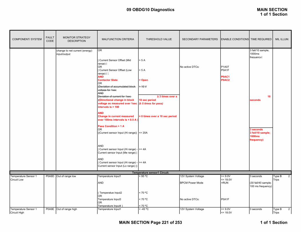
COMPONENT/ SYSTEM FAULT CODE
MONITOR STRATEGY DESCRIPTION MALFUNCTION CRITERIA THRESHOLD VALUE SECONDARY PARAMETERS ENABLE CONDITIONS TIME REQUIRED MIL ILLUM.
OR 3 fail/10 sample; 1000ms frequency)
| Current Sensor Offset (Mid range) |
> 5 A
OR No active DTCs: P1A07| Current Sensor Offset (Low range) | )
> 5 A P0A1F
AND P0AC1Contactor State = Open P0AC2OR(Deviation of accumulated block voltage for 1sec
> 10 V
ANDDeviation of current for 1sec )(Directional change in block voltage as measured over 1sec intervals is > 100
≥ 3 times over a 10 sec period(≥ 5 times for pass)
10 seconds
ANDChange in current measured over 100ms intervals is < 0.5 A )
= 0 times over a 10 sec period
Pass Condition > 1 AOR 3 seconds(|Current sensor Input (Hi range)| <= 20A 3 fail/10 sample;
1000ms frequency)
AND| Current sensor Input (Hi range) - Current sensor Input (Me range) |
>= 4A
AND| Current sensor Input (Hi range) - Current sensor Input (Lo range) |)
>= 4A
Temperature Input1 > 95 ºC 12V System Voltage >= 9.0V<= 18.0V
3 seconds
AND BPCM Power Mode =RUN (30 fail/40 sample; 100 ms frequency)
( Temperatue Input2 < 70 ºCORTemperature Input3 < 70 ºC No active DTCs: P0A1FORTemperature Input4 ) < 70 ºCTemperature Input1 < -45 ºC 12V System Voltage >= 9.0V
<= 18.0V3 seconds
change to net current (energy) input/output
Temperature Sensor 1 Circuit Low
Out of range lowP0A9DTemperature sensor1 Circuit:
Type B 2 Trips
Temperature Sensor 1 Circuit High
Out of range highP0A9E Type B 2 Trips
09 OBDG10 Diagnostics MAIN SECTION1 of 1 Section
MAIN SECTION Page 221 of 253 1 of 1 Section

COMPONENT/ SYSTEM FAULT CODE
MONITOR STRATEGY DESCRIPTION MALFUNCTION CRITERIA THRESHOLD VALUE SECONDARY PARAMETERS ENABLE CONDITIONS TIME REQUIRED MIL ILLUM.
BPCM Power Mode =RUN (30 fail/40 sample; 100 ms frequency)
No active DTCs: P0A1F| Temperature Input1 - Temperature Input2 |
> 15 ºC 12V System Voltage >= 9.0V<= 18.0V
9 seconds
AND BPCM Power Mode =RUN (90 fail/100 sample; 100ms frequency)
|Temperature Input1 - Temperature Input3|
> 15 ºC Temperature Sensor 1 Input = VALID
AND No active DTCs: P0A1F|Temperature Input1 - Temperature Input4|
> 15 ºC P0A9D
P0A9E
Temperature Input2 > 95 ºC 12V System Voltage >= 9.0V<= 18.0V
3 seconds
AND BPCM Power Mode =RUN (30 fail/40 sample; 100 ms frequency)
( Temperatue Input1 < 70 ºCORTemperature Input3 < 70 ºC No active DTCs: P0A1FORTemperature Input4 ) < 70 ºCTemperature Input2 < -45 ºC 12V System Voltage >= 9.0V
<= 18.0V3 seconds
BPCM Power Mode =RUN (30 fail/40 sample; 100 ms frequency)
No active DTCs: P0A1F| Temperature Input2 - Temperature Input1 |
> 15 ºC 12V System Voltage >= 9.0V<= 18.0V
9 seconds
AND BPCM Power Mode =RUN (90 fail/100 sample; 100ms frequency)
| Temperature Input2 - Temperature Input3 |
> 15 ºC Temperature Sensor 2 Input = VALID
AND No active DTCs: P0A1F| Temperature Input2 - Temperature Input4 |
> 15 ºC P0AC7
P0AC8
Temperature Input3 > 95 ºC 12V System Voltage >= 9.0V<= 18.0V
3 seconds
AND BPCM Power Mode =RUN (30 fail/40 sample; 100 ms frequency)
Temperature sensor3 Circuit:
Temperature Sensor 2 Circuit High
Type B 2 Trips
Type B 2 Trips
Type B 2 Trips
Rationality compares temperature with the other 3 sensor values read
Temperature Sensor 3 Circuit Low
Out of range low
P0AC6
P0ACC
Temperature Sensor 2 Circuit Low
Out of range lowP0AC7
Out of range high
Temperature Sensor 2 Circuit Rationality
P0AC8
Type B 2 Trips
Temperature sensor2 Circuit:
Temperature Sensor 1 Circuit Rationality
Rationality compares temperature with the other 3 sensor values read
P0A9C Type B 2 Trips
09 OBDG10 Diagnostics MAIN SECTION1 of 1 Section
MAIN SECTION Page 222 of 253 1 of 1 Section

COMPONENT/ SYSTEM FAULT CODE
MONITOR STRATEGY DESCRIPTION MALFUNCTION CRITERIA THRESHOLD VALUE SECONDARY PARAMETERS ENABLE CONDITIONS TIME REQUIRED MIL ILLUM.
( Temperatue Input1 < 70 ºCORTemperature Input2 < 70 ºC No active DTCs: P0A1FORTemperature Input4 ) < 70 ºCTemperature Input3 < -45 ºC 12V System Voltage >= 9.0V
<= 18.0V3 seconds
BPCM Power Mode =RUN (30 fail/40 sample; 100 ms frequency)
No active DTCs: P0A1F|Temperature Input3 - Temperature Input1|
> 15 ºC 12V System Voltage >= 9.0V<= 18.0V
9 seconds
AND BPCM Power Mode =RUN (90 fail/100 sample; 100ms frequency)
| Temperature Input3 - Temperature Input2 |
> 15 ºC Temperature Sensor 3 Input = VALID
AND No active DTCs: P0A1F|Temperature Input3 - Temperature Input4|
> 15 ºC P0ACC
P0ACD
Temperature Input4 > 95 ºC 12V System Voltage >= 9.0V<= 18.0V
3 seconds
AND BPCM Power Mode =RUN (30 fail/40 sample; 100 ms frequency)
( Temperatue Input1 < 70 ºCORTemperature Input2 < 70 ºC No active DTCs: P0A1FORTemperature Input3 ) < 70 ºCTemperature Input4 < -45 ºC 12V System Voltage >= 9.0V
<= 18.0V3 seconds
BPCM Power Mode =RUN (30 fail/40 sample; 100 ms frequency)
No active DTCs: P0A1F| Temperature Input4 - Temperature Input1 |
> 15 ºC 12V System Voltage >= 9.0V<= 18.0V
9 seconds
AND BPCM Power Mode =RUN (90 fail/100 sample; 100ms frequency)
| Temperature Input4 - Temperature Input2 |
> 15 ºC Temperature Sensor 4 Input = VALID
AND No active DTCs: P0A1F| Temperature Input4 - Temperature Input3 |
> 15 ºC P0AEA
P0AE9
Temperature Sensor 4 Circuit Rationality
P0AEBTemperature Sensor 4 Circuit High
Out of range high
Rationality compares temperature with the other 3 sensor values read
P0AE9 Type B 2 Trips
Temperature Sensor 3 Circuit Rationality
Rationality compares temperature with the other 3 sensor values read
P0ACD
P0ACB
Temperature Sensor 4 Circuit Low
Out of range lowP0AEA
Out of range high Type B 2 Trips
Temperature Sensor 3 Circuit High
Type B 2 Trips
Type B 2 Trips
Type B 2 Trips
Temperature sensor4 Circuit:
09 OBDG10 Diagnostics MAIN SECTION1 of 1 Section
MAIN SECTION Page 223 of 253 1 of 1 Section
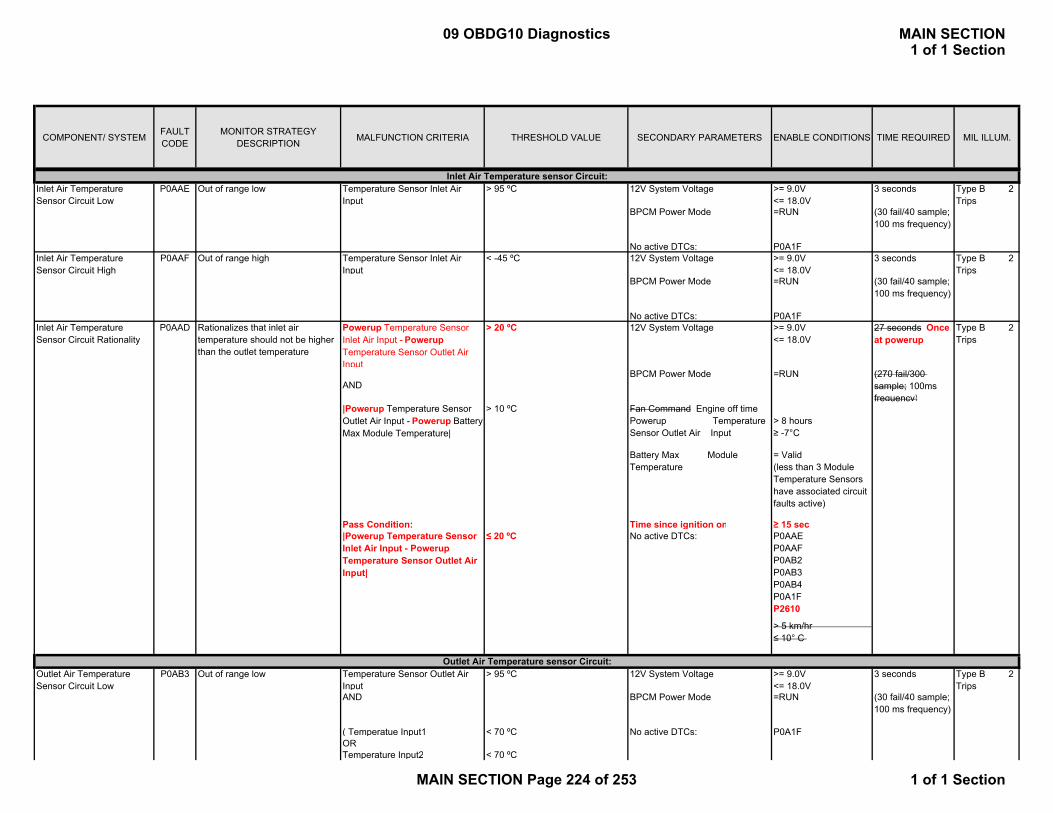
COMPONENT/ SYSTEM FAULT CODE
MONITOR STRATEGY DESCRIPTION MALFUNCTION CRITERIA THRESHOLD VALUE SECONDARY PARAMETERS ENABLE CONDITIONS TIME REQUIRED MIL ILLUM.
Temperature Sensor Inlet Air Input
> 95 ºC 12V System Voltage >= 9.0V<= 18.0V
3 seconds
BPCM Power Mode =RUN (30 fail/40 sample; 100 ms frequency)
No active DTCs: P0A1FTemperature Sensor Inlet Air Input
< -45 ºC 12V System Voltage >= 9.0V<= 18.0V
3 seconds
BPCM Power Mode =RUN (30 fail/40 sample; 100 ms frequency)
No active DTCs: P0A1FPowerup Temperature Sensor Inlet Air Input - Powerup Temperature Sensor Outlet Air Input
> 20 ºC 12V System Voltage >= 9.0V<= 18.0V
27 seconds Once at powerup
ANDBPCM Power Mode =RUN (270 fail/300
sample; 100ms frequency)
|Powerup Temperature Sensor Outlet Air Input - Powerup Battery Max Module Temperature|
> 10 ºC Fan Command Engine off time Powerup Temperature Sensor Outlet Air Input
> 8 hours ≥ -7°C
Battery Max Module Temperature
= Valid (less than 3 Module Temperature Sensors have associated circuit faults active)
Pass Condition: Time since ignition on ≥ 15 sec|Powerup Temperature Sensor Inlet Air Input - Powerup Temperature Sensor Outlet Air Input|
≤ 20 ºC No active DTCs: P0AAEP0AAFP0AB2P0AB3P0AB4P0A1FP2610
> 5 km/hr ≤ 10° C
Temperature Sensor Outlet Air Input
> 95 ºC 12V System Voltage >= 9.0V<= 18.0V
3 seconds
AND BPCM Power Mode =RUN (30 fail/40 sample; 100 ms frequency)
( Temperatue Input1 < 70 ºC No active DTCs: P0A1FORTemperature Input2 < 70 ºC
Inlet Air Temperature Sensor Circuit High
Outlet Air Temperature Sensor Circuit Low
Out of range lowP0AB3
Out of range high
Inlet Air Temperature Sensor Circuit Rationality
Rationalizes that inlet air temperature should not be higher than the outlet temperature
P0AAF
P0AAD
Outlet Air Temperature sensor Circuit:
Inlet Air Temperature Sensor Circuit Low
Out of range lowP0AAEInlet Air Temperature sensor Circuit:
Type B 2 Trips
Type B 2 Trips
Type B 2 Trips
Type B 2 Trips
09 OBDG10 Diagnostics MAIN SECTION1 of 1 Section
MAIN SECTION Page 224 of 253 1 of 1 Section

COMPONENT/ SYSTEM FAULT CODE
MONITOR STRATEGY DESCRIPTION MALFUNCTION CRITERIA THRESHOLD VALUE SECONDARY PARAMETERS ENABLE CONDITIONS TIME REQUIRED MIL ILLUM.
ORTemperature Input3 < 70 ºCORTemperature Input4 ) < 70 ºC
Temperature Sensor Outlet Air Input
< -45 ºC 12V System Voltage >= 9.0V<= 18.0V
3 seconds
BPCM Power Mode =RUN (30 fail/40 sample; 100 ms frequency)
No active DTCs: P0A1FTemperature Sensor Outlet Air Input - BPCM High Voltage Battery Pack Max Module Temperature
> 10 ºC 12V System Voltage >= 9.0V<= 18.0V
9 seconds
Fan Command = ON (90 fail/100 sample; 100ms frequency)
BPCM Power Mode =RUNNo active DTCs: P0A1F, P0A9C, P0A9D
P0A9E, P0AB3, P0AB4
P0AC6, P0AC7, P0AC8P0ACB, P0ACC, P0ACDP0AE9, P0AEA, P0AEB
Fan control signal monitor voltage >= 0.9 V 12V System voltage >= 9.0 V<= 18.0 V
1 sec (10fails / 20samples; 100msec freq.)
BPCM Power Mode =RUNFan command = OFFNo active DTCs: P0A1F
Checks Functionality of fan control
Fan control signal monitor voltage AND
>= 2.3 VOR<= 0.5 V
12V System voltage >= 9.0 V<= 18.0 V
5 sec (50fails / 50samples; 100msec freq.)
Fan commandAND
= ON BPCM Power Mode =RUN
Fan speed]OR
>= 35 % for >=3 seconds No active DTCs: P0A1F
[Fan commandAND
= OFF 9 sec (90fails / 100samples; 100msec freq.)
Fan Unit Failure
Battery Cooling Fan:
P0A81
P0AB4
Fan Relay Welded
Outlet Air Temperature Sensor Circuit High
Out of range high
Outlet Air Temperature Sensor Circuit Rationality
Rationalizes that the outlet air temperature should not be higher than the highest battery pack module temperature
P0AB2
P0BC1
Type B 2 Trips
Type B 2 Trips
Type B 2 Trips
Type B 2 Trips
09 OBDG10 Diagnostics MAIN SECTION1 of 1 Section
MAIN SECTION Page 225 of 253 1 of 1 Section

COMPONENT/ SYSTEM FAULT CODE
MONITOR STRATEGY DESCRIPTION MALFUNCTION CRITERIA THRESHOLD VALUE SECONDARY PARAMETERS ENABLE CONDITIONS TIME REQUIRED MIL ILLUM.
Fan control signal monitor voltage]OR
> 4.0 VAND< 7.0 V
Fan control signal monitor voltageOR
> 7.0 V 3 sec (30fails / 40samples; 100msec freq.)
Fan speed feedback signalOR
> 9.0 V
[Fan commandAND
= OFF 9 sec (90fails / 100samples; 100msec freq.)
Fan speed feedback signal]OR
> 4.0 VAND< 7.0 V
[Fan commandAND
= ON 3 sec (30fails / 40samples; 100msec freq.)
Fan speed feedback signal] < 0.15 V
Maximum Battery Module Temperature
> Temperature as defined in table below:Inlet Temp vs. Max Module Temp
C C-30 45-20 45-10 45-5 45 0 46 5 48 10 49 15 50 20 52 25 54 30 56 35 58 40 61 45 65 50 70 60 80
12V System voltage >= 9.0 V<= 18.0 V
120 sec (1200fails / 1200samples; 100msec freq.)
Battery Cooling System Performance
P0C32 Type B 2 Trips
09 OBDG10 Diagnostics MAIN SECTION1 of 1 Section
MAIN SECTION Page 226 of 253 1 of 1 Section

COMPONENT/ SYSTEM FAULT CODE
MONITOR STRATEGY DESCRIPTION MALFUNCTION CRITERIA THRESHOLD VALUE SECONDARY PARAMETERS ENABLE CONDITIONS TIME REQUIRED MIL ILLUM.
Battery Max Module Temperature
= Valid(less than 3 Module Temperature Sensors have associated circuit faults active)
No active DTCs: P0AAE, P0AAF, P0A1F
Fan command = ON
Out of range Current Sensor Supply Voltage < 4.8 V 12V System Voltage >= 9.0V<= 18.0V
0.8 sec
ORCurrent Sensor Supply Voltage > 5.2 V No active DTCs: P0A1F (8 fail/10 sample;
100 ms frequency)
HVIL Current Output > 5 mA 12V System Voltage >= 9.0V<= 18.0V
10 ms
AND BPCM Power Mode = RUNHVIL Current Output < 18 mA HVIL State = Asserted (1 fail/1 sample; 10
ms frequency)AND No active DTCs: P0A1FHVIL Current Input < 5 mAHVIL Current Output < 5 mA 12V System Voltage >= 9.0V
<= 18.0V10 ms
AND BPCM Power Mode = RUN (1 fail/1 sample; 10 ms frequency)
HVIL Current Input > 35 mA HVIL State = AssertedNo active DTCs: P0A1F
HVIL Current Output < 5 mA 12V System Voltage >= 9.0V<= 18.0V
10 ms
AND BPCM Power Mode = RUN (1 fail/1 sample; 10 ms frequency)
HVIL Current Input < 5 mA HVIL State = AssertedNo active DTCs: P0A1F
([BPCM High Voltage pack Voltage AND
< 60V, 12V System Voltage => 9.0 V=< 18.0 V
1times
Precharge Time] =0msAND BPCM Power Mode = RUN[| BPCM High Voltage pack Voltage - Sum of battery block voltages |
=< 23V No active DTCs: P0A1F
AND Precharge Time] ) =<20msOR OR
Current Sensor Voltage Supply:
High Voltage Interlock Circuit:P1AE3 Out of range low
Current Sensor Voltage Supply
P1A07 Type A 1 Trip
P1AE4
P1AE2
Special Type "C" NO MIL
High Voltage Interlock Circuit High
Out of range high
Special Type "C" NO MIL
High Voltage Interlock Circuit Low
High Voltage Interlock Circuit Open
Open Special Type "C" NO MIL
Pre-Charge Voltage :Pre-Charge too Fast P0C77 HV bus = Open Special Type
"C" NO MIL
09 OBDG10 Diagnostics MAIN SECTION1 of 1 Section
MAIN SECTION Page 227 of 253 1 of 1 Section

COMPONENT/ SYSTEM FAULT CODE
MONITOR STRATEGY DESCRIPTION MALFUNCTION CRITERIA THRESHOLD VALUE SECONDARY PARAMETERS ENABLE CONDITIONS TIME REQUIRED MIL ILLUM.
(BPCM High Voltage Battery Pack Current
=> 25A
AND Precharge Time) > 100ms
Voltage deviation is high Maximum | Block Voltage(n) - Block Voltage (n+1) |
> 1.5 V BPCM Power Mode = RUN 3 seconds
12V System Voltage >= 9.0V<= 18.0V
(3 fail/3 sample; 1 second frequency)
Battery current >0.2AMin. battery temp. >= -7ºCAny voltages associated with these active DTC's are not used in calculation of maximum voltage deviation
P0B3D, P0B3E, P0B3C P0B42, P0B43, P0B41, P0B47, P0B48, P0B46, P0B4C, P0B4D, P0B4B, P0B51, P0B52, P0B50, P0B56, P0B57, P0B55, P0B5B, P0B5C,P0B5A
P0B60, P0B61, P0B5F
P0B65, P0B66, P0B64
P0B6A, P0B6B, P0B69
P0B6F, P0B70, P0B6E
P0B74, P0B75, P0B73
P0B79, P0B7A, P0B78
P0B7E, P0B7F, P0B7D
P0B83, P0B84, P0B82
P0B88, P0B89, P0B87
P0B8D, P0B8E, P0B8CP0B92, P0B93, P0B91
P0B97, P0B98, P0B96
P0B9C, P0B9D, P0B9BP0A1F
High Voltage Battery:
HV bus = Short
Type B 2 Trips
Battery Module – Voltage deviation EOL
P0BBD
09 OBDG10 Diagnostics MAIN SECTION1 of 1 Section
MAIN SECTION Page 228 of 253 1 of 1 Section

COMPONENT/ SYSTEM FAULT CODE
MONITOR STRATEGY DESCRIPTION MALFUNCTION CRITERIA THRESHOLD VALUE SECONDARY PARAMETERS ENABLE CONDITIONS TIME REQUIRED MIL ILLUM.
Sum of battery block voltages > 408 V BPCM Power Mode = RUN 4 seconds
ORAny Block Voltage N
> 20.4 V 12V System Voltage >= 9.0V<= 18.0V
(40 fail/40 sample; 100 ms frequency)
Block voltage rationality = Pass (at least 1block)
Any voltages associated with these active DTC's are not used in determination of voltage too high
P0B3D, P0B3E, P0B3C, P0B42, P0B43, P0B41, P0B47, P0B48, P0B46, P0B4C, P0B4D, P0B4B, P0B51, P0B52, P0B50, P0B56, P0B57, P0B55,
OR 2 seconds (20 fail/20 sample; 100 ms frequency)
P0B5B, P0B5C,P0B5A
P0B60, P0B61, P0B5F
P0B65, P0B66, P0B64
P0B6A, P0B6B, P0B69
P0B6F, P0B70, P0B6E
P0B74, P0B75, P0B73
P0B79, P0B7A, P0B78
P0B7E, P0B7F, P0B7D
P0B83, P0B84, P0B82
P0B88, P0B89, P0B87
P0B8D, P0B8E, P0B8CP0B92, P0B93, P0B91
P0B97, P0B98, P0B96
P0B9C, P0B9D, P0B9BP0A1F
Voltage too low Sum of battery block voltages < 168 V BPCM Power Mode = RUN 4 seconds
ORAny Block Voltage N
< 8.4 V 12V System Voltage >= 9.0V<= 18.0V
(40 fail/40 sample; 100 ms frequency)
Battery Module – Over Voltage
P1A4E Voltage too high Special Type "C" NO MIL
Battery Module – Under Voltage
P1A1F Special Type "C" NO MIL
09 OBDG10 Diagnostics MAIN SECTION1 of 1 Section
MAIN SECTION Page 229 of 253 1 of 1 Section
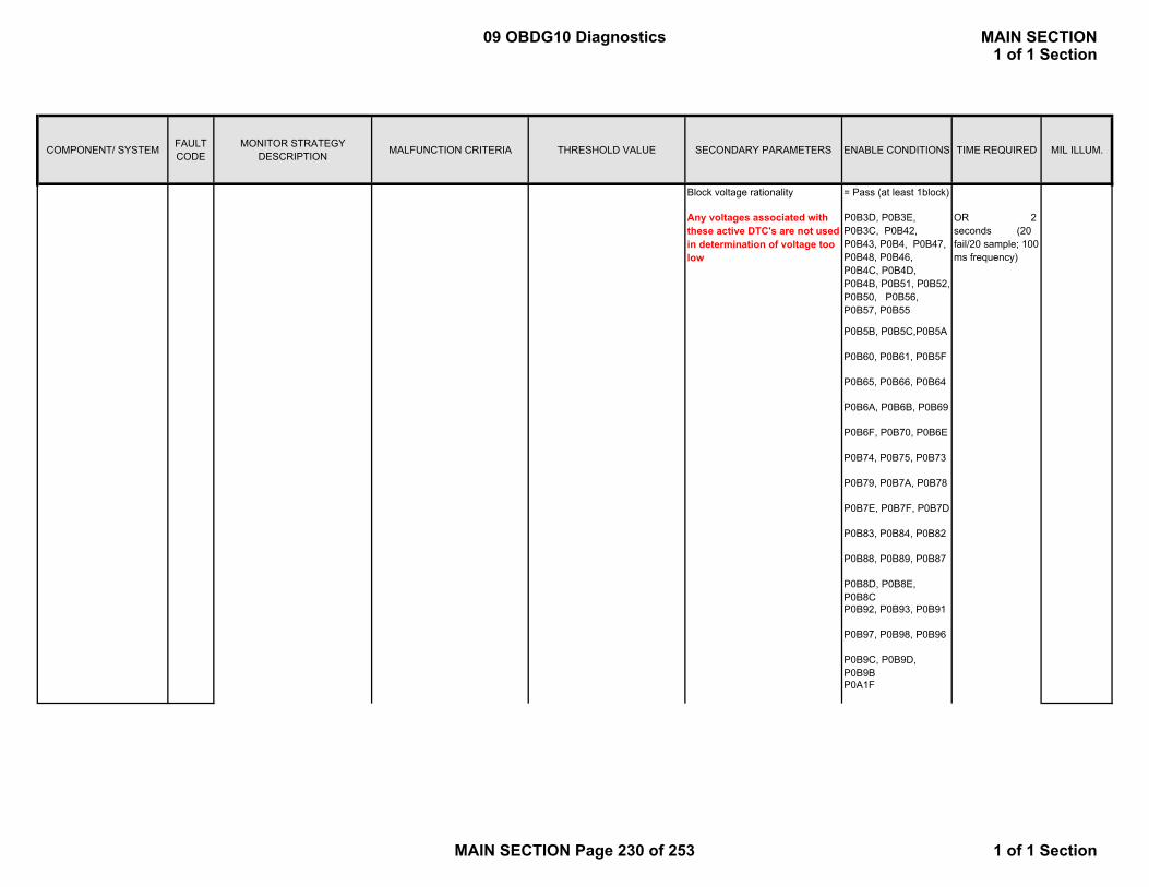
COMPONENT/ SYSTEM FAULT CODE
MONITOR STRATEGY DESCRIPTION MALFUNCTION CRITERIA THRESHOLD VALUE SECONDARY PARAMETERS ENABLE CONDITIONS TIME REQUIRED MIL ILLUM.
Block voltage rationality = Pass (at least 1block)
Any voltages associated with these active DTC's are not used in determination of voltage too low
P0B3D, P0B3E, P0B3C, P0B42, P0B43, P0B4, P0B47, P0B48, P0B46, P0B4C, P0B4D, P0B4B, P0B51, P0B52, P0B50, P0B56, P0B57, P0B55
OR 2 seconds (20 fail/20 sample; 100 ms frequency)
P0B5B, P0B5C,P0B5A
P0B60, P0B61, P0B5F
P0B65, P0B66, P0B64
P0B6A, P0B6B, P0B69
P0B6F, P0B70, P0B6E
P0B74, P0B75, P0B73
P0B79, P0B7A, P0B78
P0B7E, P0B7F, P0B7D
P0B83, P0B84, P0B82
P0B88, P0B89, P0B87
P0B8D, P0B8E, P0B8CP0B92, P0B93, P0B91
P0B97, P0B98, P0B96
P0B9C, P0B9D, P0B9BP0A1F
09 OBDG10 Diagnostics MAIN SECTION1 of 1 Section
MAIN SECTION Page 230 of 253 1 of 1 Section
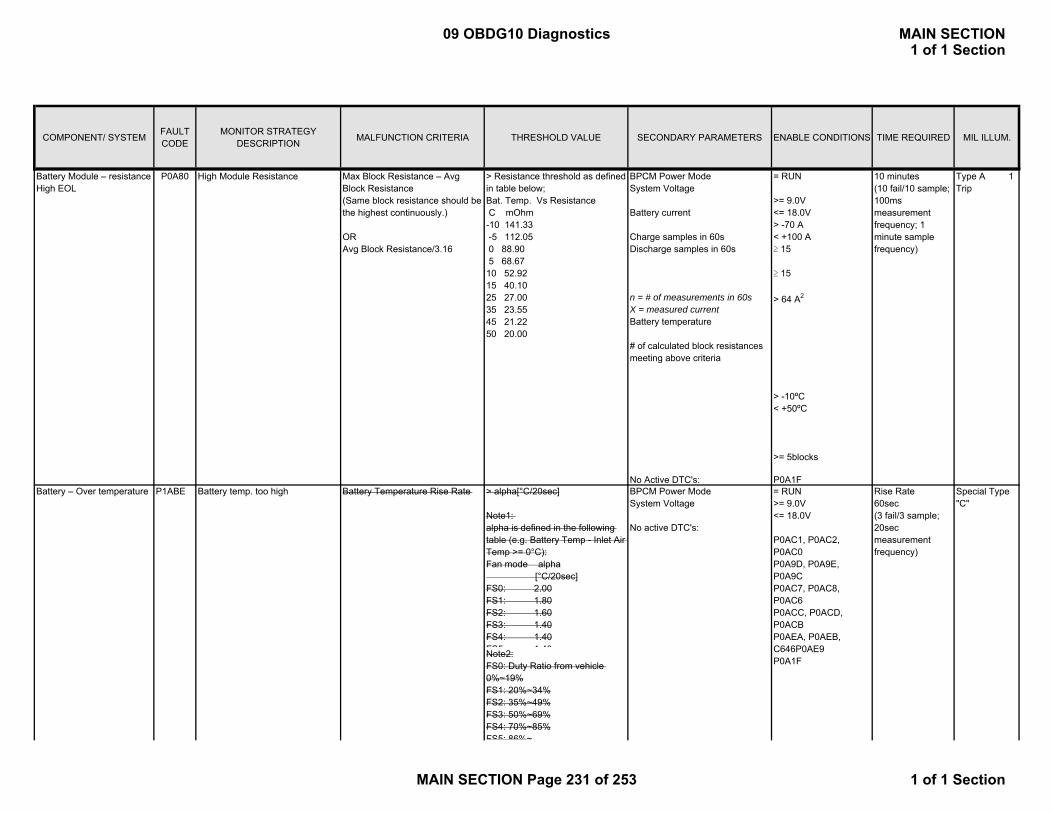
COMPONENT/ SYSTEM FAULT CODE
MONITOR STRATEGY DESCRIPTION MALFUNCTION CRITERIA THRESHOLD VALUE SECONDARY PARAMETERS ENABLE CONDITIONS TIME REQUIRED MIL ILLUM.
Max Block Resistance – Avg Block Resistance (Same block resistance should be the highest continuously.)
ORAvg Block Resistance/3.16
> Resistance threshold as defined in table below;Bat. Temp. Vs Resistance C mOhm-10 141.33 -5 112.05 0 88.90 5 68.6710 52.9215 40.1025 27.0035 23.5545 21.2250 20.00
BPCM Power ModeSystem Voltage
Battery current
Charge samples in 60sDischarge samples in 60s
n = # of measurements in 60sX = measured currentBattery temperature
# of calculated block resistances meeting above criteria
= RUN
>= 9.0V<= 18.0V> -70 A< +100 A≥ 15
≥ 15
> 64 A2
> -10ºC< +50ºC
>= 5blocks
10 minutes(10 fail/10 sample; 100ms measurement frequency; 1 minute sample frequency)
Type A 1 Trip
No Active DTC's: P0A1F> alpha[°C/20sec]
Note1: alpha is defined in the following table (e.g. Battery Temp - Inlet Air Temp >= 0°C):Fan mode alpha [°C/20sec]FS0: 2.00FS1: 1.80FS2: 1.60FS3: 1.40FS4: 1.40FS5 1 40
Special Type "C"
Note2:FS0: Duty Ratio from vehicle 0%~19%FS1: 20%~34%FS2: 35%~49%FS3: 50%~69%FS4: 70%~85%FS5: 86%~
Battery Module – resistance High EOL
High Module Resistance
= RUN>= 9.0V<= 18.0V P0AC1, P0AC2, P0AC0P0A9D, P0A9E, P0A9CP0AC7, P0AC8, P0AC6P0ACC, P0ACD, P0ACBP0AEA, P0AEB, C646P0AE9P0A1F
BPCM Power ModeSystem Voltage
No active DTC's:
Rise Rate60sec(3 fail/3 sample; 20sec measurement frequency)
P0A80
Battery – Over temperature P1ABE Battery temp. too high Battery Temperature Rise Rate
09 OBDG10 Diagnostics MAIN SECTION1 of 1 Section
MAIN SECTION Page 231 of 253 1 of 1 Section

COMPONENT/ SYSTEM FAULT CODE
MONITOR STRATEGY DESCRIPTION MALFUNCTION CRITERIA THRESHOLD VALUE SECONDARY PARAMETERS ENABLE CONDITIONS TIME REQUIRED MIL ILLUM.
If 2 or more Battery temperatures meet the right conditions;
[BPCM High Voltage Battery Pack Max Module Temperature > 65deg.C
Over Temp.5sec(50 fail/50 sample; 100ms measurement frequency)
If 1 Battery temperature meets the right condition:
70 deg C < [BPCM High Voltage Battery Pack Max Module Temperature <= 95 deg CANDTime ≥ 5sec
Extreme Over Temp.5sec(50 fail/50 sample; 100ms measurement frequency)
Controller – RAM Error P1A05 Microcomputer detects RAM Failure
Read value does not match write value.
(Conduct a verify check by writing 4bytes pitch from the first digit accordingly.If the read value does not match write value when the test pattern of 0x55555555 and 0xAAAAAAAA are written.)
BPCM Power Mode = RUN 100ms Type A 1 Trip
Controller – ROM Error P1A06 Microcomputer detects ROM Failure
Calculated CS of ROM and the already written CS in the GMHeader area is not the same.
BPCM Power Mode = RUN 100ms Type A 1 Trip
Error occur at mirror check during EEPROM downloading
(If any of following failures is detected by verifying check sum during EEPROM read at the BPCM start-up.)
BPCM Power Mode = RUN 100ms Type A 1 Trip
a) Calibration areab) Parameter areac) Diag area (status history) d) Diag area (X/Y counter)
Microcomputer detects watchdog timeout.
Watchdog timer interruption occurred and the BPCM is reset.
BPCM Power Mode = RUN 100ms
ORProcessor StackOverflow Usage of micro processor stack > 80% 10 ms
ORProgram Processing Time-out Previously activated DMA
transmission incomplete10 ms
ORProgram Processing Time-out 10msec transaction time > 10ms
(No waiting time available during 10ms process waiting time.)
10 ms
OR
Controller – EEPROM Error P1A01
Micro controller failure P0A1F
Controller Faults
Type A 1 Trip
09 OBDG10 Diagnostics MAIN SECTION1 of 1 Section
MAIN SECTION Page 232 of 253 1 of 1 Section
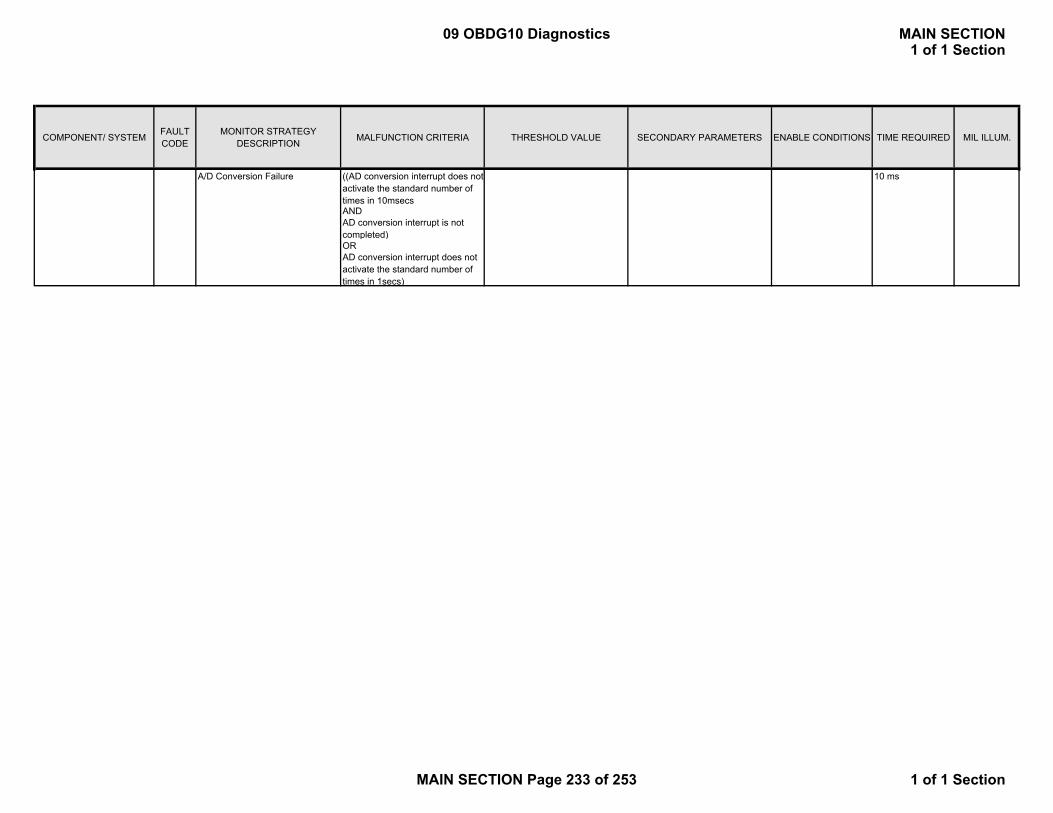
COMPONENT/ SYSTEM FAULT CODE
MONITOR STRATEGY DESCRIPTION MALFUNCTION CRITERIA THRESHOLD VALUE SECONDARY PARAMETERS ENABLE CONDITIONS TIME REQUIRED MIL ILLUM.
A/D Conversion Failure ((AD conversion interrupt does not activate the standard number of times in 10msecs
10 ms
ANDAD conversion interrupt is not completed)ORAD conversion interrupt does not activate the standard number of times in 1secs)
09 OBDG10 Diagnostics MAIN SECTION1 of 1 Section
MAIN SECTION Page 233 of 253 1 of 1 Section
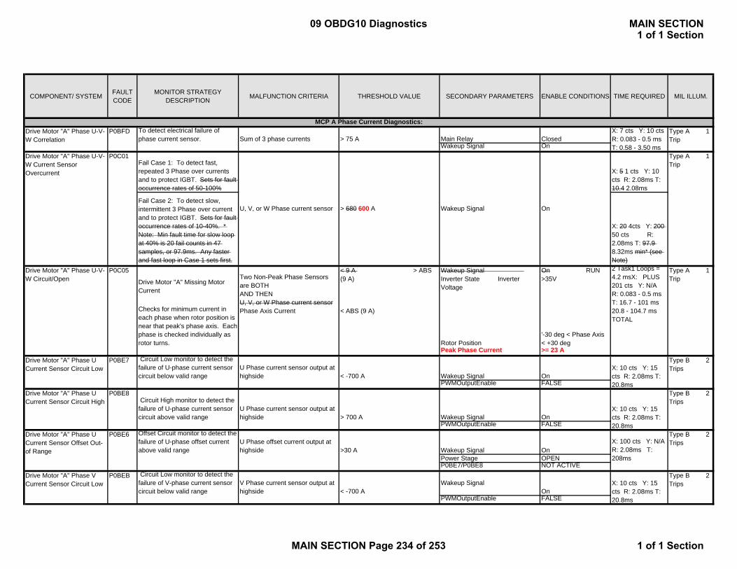
COMPONENT/ SYSTEM FAULT CODE
MONITOR STRATEGY DESCRIPTION MALFUNCTION CRITERIA THRESHOLD VALUE SECONDARY PARAMETERS ENABLE CONDITIONS TIME REQUIRED MIL ILLUM.
To detect electrical failure of phase current sensor. Sum of 3 phase currents > 75 A Main Relay Closed
Wakeup Signal OnDrive Motor "A" Phase U-V-W Current Sensor Overcurrent
P0C01Fail Case 1: To detect fast, repeated 3 Phase over currents and to protect IGBT. Sets for fault occurrence rates of 50-100%
X: 5 1 cts Y: 10 cts R: 2.08ms T: 10.4 2.08ms
Fail Case 2: To detect slow, intermittent 3 Phase over current and to protect IGBT. Sets for fault occurrence rates of 10-40%. * Note: Min fault time for slow loop at 40% is 20 fail counts in 47 samples, or 97.9ms. Any faster and fast loop in Case 1 sets first.
X: 20 4cts Y: 200 50 cts R: 2.08ms T: 97.9 8.32ms min* (see Note)
Drive Motor "A" Phase U-V-W Circuit/Open
P0C05
Drive Motor "A" Missing Motor Current
Two Non-Peak Phase Sensors are BOTH AND THEN U, V, or W Phase current sensor
< 9 A > ABS (9 A)
Wakeup Signal Inverter State Inverter Voltage
On RUN >35V
2 Task1 Loops = 4.2 msX: PLUS 201 cts Y: N/A R: 0.083 - 0.5 ms T: 16.7 - 101 ms
Type A 1 Trip
Checks for minimum current in each phase when rotor position is near that peak's phase axis. Each phase is checked individually as rotor turns.
Phase Axis Current < ABS (9 A)
Rotor Position'-30 deg < Phase Axis < +30 deg
20.8 - 104.7 ms TOTAL
Peak Phase Current >= 23 A Circuit Low monitor to detect the failure of U-phase current sensor circuit below valid range
U Phase current sensor output at highside < -700 A Wakeup Signal On
PWMOutputEnable FALSE
Circuit High monitor to detect the failure of U-phase current sensor circuit above valid range
U Phase current sensor output at highside > 700 A Wakeup Signal On
PWMOutputEnable FALSEOffset Circuit monitor to detect the failure of U-phase offset current above valid range
U Phase offset current output at highside >30 A Wakeup Signal On
Power Stage OPENP0BE7/P0BE8 NOT ACTIVE
Circuit Low monitor to detect the failure of V-phase current sensor circuit below valid range
V Phase current sensor output at highside < -700 A
Wakeup SignalOn
PWMOutputEnable FALSE
MCP A Phase Current Diagnostics:
P0BE8
P0BE6
P0BEBX: 10 cts Y: 15 cts R: 2.08ms T: 20.8ms
Drive Motor "A" Phase U-V-W Correlation
Drive Motor "A" Phase U Current Sensor Circuit Low
Drive Motor "A" Phase U Current Sensor Circuit High
Drive Motor "A" Phase U Current Sensor Offset Out-of Range
Drive Motor "A" Phase V Current Sensor Circuit Low
Type A 1 Trip
Type B 2 Trips
Type B 2 Trips
Type B 2 Trips
Type B 2 Trips
Type A 1 Trip
P0BFD
U, V, or W Phase current sensor
P0BE7
On
X: 7 cts Y: 10 cts R: 0.083 - 0.5 ms T: 0.58 - 3.50 ms
> 680 600 A Wakeup Signal
X: 10 cts Y: 15 cts R: 2.08ms T: 20.8ms
X: 10 cts Y: 15 cts R: 2.08ms T: 20.8ms
X: 100 cts Y: N/A R: 2.08ms T: 208ms
09 OBDG10 Diagnostics MAIN SECTION1 of 1 Section
MAIN SECTION Page 234 of 253 1 of 1 Section

COMPONENT/ SYSTEM FAULT CODE
MONITOR STRATEGY DESCRIPTION MALFUNCTION CRITERIA THRESHOLD VALUE SECONDARY PARAMETERS ENABLE CONDITIONS TIME REQUIRED MIL ILLUM.
MCP A Ph C Di i Circuit High monitor to detect the failure of V-phase current sensor circuit above valid range
V Phase current sensor output current at highside > 700 A Wakeup Signal On
PWMOutputEnable FALSEOffset Circuit monitor to detect the failure of U-phase offset current above valid range
V Phase offset current output at highside >30 A Wakeup Signal On
Power Stage OPENP0BEB/P0BEC NOT ACTIVE
Circuit Low monitor to detect the failure of W-phase current sensor circuit below valid range
W Phase current sensor output at highside < -700 A
Wakeup SignalOn
PWMOutputEnable FALSE
Circuit High monitor to detect the failure of W-phase current sensor circuit above valid range
W Phase current sensor output at highside > 700 A
Wakeup SignalOn
PWMOutputEnable FALSEOffset Circuit monitor to detect the failure of U-phase offset current above valid range
W Phase offset current output at highside >30 A Wakeup Signal On
Power Stage OPENP0BEF/P0BF0 NOT ACTIVE
Drive Motor "A" Inverter Performance
P0A78Detects IGBT Desaturation Faults
Phase A, B, or C High or Low Side Devices OVERDRIVEN (Status Fault Bit) Wakeup Signal On
X: 1 ct Y: N/A R: 2.08ms T: 2.08ms
Type A 1 Trip
Drive Motor "A" Inverter Power Supply Circuit/Open
P0C0B
Detects IGBT Bias Faults Phase A, B, or C Power Supply FAILED (Status Fault Bit)
Inverter State
Run/Crank Voltage OR Powertrain Relay Voltage
Initialization Complete
> 9.5 Volts OR < 18 Volts
X: 1 ct Y: N/A R: 2.08ms T: 2.08ms
Type A 1 Trip
Drive Motor "A" Hybrid Battery System Voltage High
P1AEE To detect over voltage and to protect TPIM Vdc Circuit
HV Sensor Voltage Average of first and third previous HV readings > 475V WakeUp Signal On
X: 5 cts Y: N/A R: 0.083 - 0.5 ms T: 0.42 - 2.50 ms
Type A 1 Trip
Drive Motor "A" Control Module Hybrid Battery Voltage Sense Circuit Low Voltage
P1AE8 Circuit Low monitor to detect the failure of HV output voltage sensor circuit below valid range HV Sensor Voltage <0V Inverter State Initialization Complete
X: 50 70 cts Y: 100 cts R: 2.08ms T: 104 146ms
Type B 2 Trips
Drive Motor "A" Control Module Hybrid Battery Voltage Sense Circuit High Voltage
P1AE9 Circuit High monitor to detect the failure of HV output voltage sensor circuit above valid range HV Sensor Voltage >564 500V Inverter State Initialization Complete
X: 50 cts Y: 100 cts R: 2.08ms T: 104ms
Type B 2 Trips
To check correlation of HV_MCP with HV_Midpack and HV_Battery Voltages.
ABS(MCP HV voltage - HV Battery voltage) >= 34 V Valid HV CAN Msg TRUEOR AND WakeUp Signal ON
P1AEC
P0BEE
P0BF0
P0BEA
P0BEC
X: 10 cts Y: 15 cts R: 2.08ms T: 20.8ms
X: 100 cts Y: N/A R: 2.08ms T: 208ms
X: 10 cts Y: 15 cts R: 2.08ms T: 20.8ms
Drive Motor "A" Phase V Current Sensor Offset Out-of Range
X: 10 cts Y: 15 cts R: 2.08ms T: 20.8ms
X: 100 cts Y: N/A R: 2.08ms T: 208ms
Drive Motor "A" Phase V Current Sensor Circuit High
Type B 2 Trips
Type B 2 Trips
Type B 2 Trips
Type B 2 Trips
Type B 2 Trips
Type A 1 Trip
Drive Motor "A" Control Module Hybrid Battery System Voltage
X: 18 cts Y: 30
P0BEF
MCP A IGBT Diagnostics
MCP A High Voltage (HV) Diagnostics:
Drive Motor "A" Phase W Current Sensor Offset Out-of Range
Drive Motor "A" Phase W Current Sensor Circuit Low
Drive Motor "A" Phase W Current Sensor Circuit High
09 OBDG10 Diagnostics MAIN SECTION1 of 1 Section
MAIN SECTION Page 235 of 253 1 of 1 Section
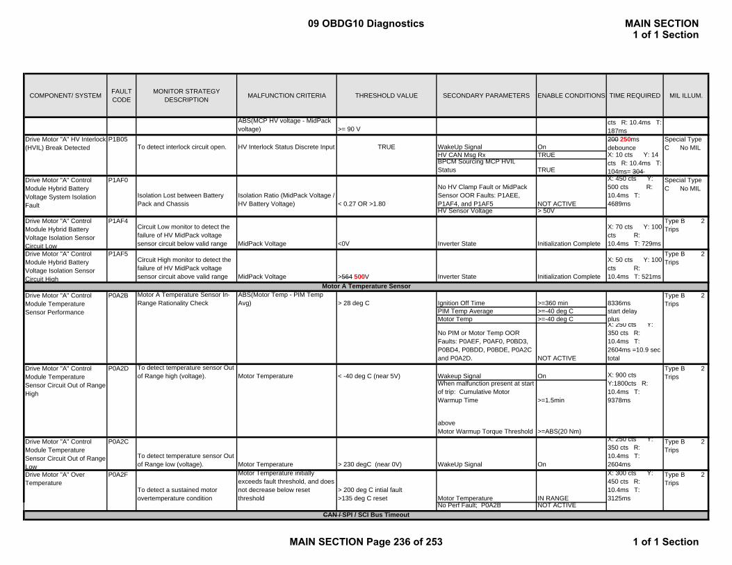
COMPONENT/ SYSTEM FAULT CODE
MONITOR STRATEGY DESCRIPTION MALFUNCTION CRITERIA THRESHOLD VALUE SECONDARY PARAMETERS ENABLE CONDITIONS TIME REQUIRED MIL ILLUM.
MCP A Ph C Di iABS(MCP HV voltage - MidPack voltage) >= 90 V
To detect interlock circuit open. HV Interlock Status Discrete Input TRUE WakeUp Signal On200 250ms debounce
HV CAN Msg Rx TRUEBPCM Sourcing MCP HVILStatus TRUE
Isolation Lost between Battery Pack and Chassis
Isolation Ratio (MidPack Voltage / HV Battery Voltage) < 0.27 OR >1.80
No HV Clamp Fault or MidPack Sensor OOR Faults: P1AEE, P1AF4, and P1AF5 NOT ACTIVE
X: 450 cts Y: 500 cts R: 10.4ms T: 4689ms
HV Sensor Voltage > 50VDrive Motor "A" Control Module Hybrid Battery Voltage Isolation Sensor Circuit Low
P1AF4Circuit Low monitor to detect the failure of HV MidPack voltage sensor circuit below valid range MidPack Voltage <0V Inverter State Initialization Complete
X: 70 cts Y: 100 cts R: 10.4ms T: 729ms
Type B 2 Trips
Drive Motor "A" Control Module Hybrid Battery Voltage Isolation Sensor Circuit High
P1AF5Circuit High monitor to detect the failure of HV MidPack voltage sensor circuit above valid range MidPack Voltage >564 500V Inverter State Initialization Complete
X: 50 cts Y: 100 cts R: 10.4ms T: 521ms
Type B 2 Trips
Motor A Temperature Sensor In-Range Rationality Check
ABS(Motor Temp - PIM Temp Avg) > 28 deg C Ignition Off Time >=360 min 8336ms
PIM Temp Average >=-40 deg C start delayMotor Temp >=-40 deg C plus
No PIM or Motor Temp OOR Faults: P0AEF, P0AF0, P0BD3, P0BD4, P0BDD, P0BDE, P0A2C and P0A2D. NOT ACTIVE
X: 250 cts Y: 350 cts R: 10.4ms T: 2604ms =10.9 sec total
P0A2D To detect temperature sensor Out of Range high (voltage). Motor Temperature < -40 deg C (near 5V) Wakeup Signal On
When malfunction present at start of trip: Cumulative Motor Warmup Time >=1.5min
aboveMotor Warmup Torque Threshold >=ABS(20 Nm)
Drive Motor "A" Control Module Temperature Sensor Circuit Out of Range Low
P0A2C
To detect temperature sensor Out of Range low (voltage). Motor Temperature > 230 degC (near 0V) WakeUp Signal On
X: 250 cts Y: 350 cts R: 10.4ms T: 2604ms
Type B 2 Trips
Drive Motor "A" Over Temperature
P0A2F
To detect a sustained motor overtemperature condition
Motor Temperature initially exceeds fault threshold, and does not decrease below reset threshold
> 200 deg C intial fault>135 deg C reset Motor Temperature IN RANGE
X: 300 cts Y: 450 cts R: 10.4ms T: 3125ms
Type B 2 Trips
No Perf Fault; P0A2B NOT ACTIVE
P1B05
P1AF0
Type B 2 Trips
P0A2B
Drive Motor "A" Control Module Temperature Sensor Circuit Out of Range High
Special Type C No MIL
Special Type C No MIL
CAN / SPI / SCI Bus Timeout
Type B 2 Trips
X: 10 cts Y: 14 cts R: 10.4ms T: 104ms= 304
Drive Motor "A" Control Module Temperature Sensor Performance
Drive Motor "A" HV Interlock (HVIL) Break Detected
Drive Motor "A" Control Module Hybrid Battery Voltage System Isolation Fault
X: 900 cts Y:1800cts R: 10.4ms T: 9378ms
cts R: 10.4ms T: 187ms
Motor A Temperature Sensor
09 OBDG10 Diagnostics MAIN SECTION1 of 1 Section
MAIN SECTION Page 236 of 253 1 of 1 Section

COMPONENT/ SYSTEM FAULT CODE
MONITOR STRATEGY DESCRIPTION MALFUNCTION CRITERIA THRESHOLD VALUE SECONDARY PARAMETERS ENABLE CONDITIONS TIME REQUIRED MIL ILLUM.
MCP A Ph C Di iP1AFCTo detect loss of communication on the SPI bus with the HCP module SPI Receive Timeout flag TRUE
Inverter State
Run/Crank Voltage OR Powertrain Relay Voltage
Run
> 9.5 Volts OR < 18 Volts
X: 97 241cts Y: N/A R:10.42ms T: 1010
# Timeout Counts 7 2510msDrive Motor "A" Control Module Lost Communication With SCI Bus
P1AFDTo detect loss of communication on the SCI bus with Motor "B" Control ModuleSCI Diag Timeout SCI_Rx_Timeout TRUE Wakeup Signal On
X: 200 cts Y: 300 cts R: 10.4ms T: 2083ms
Type B 2 Trips
Sensor Reference Voltage "A" Circuit Low
P0642
Detects Sensor Voltage (5V) below an acceptable threshold. Scaled 5V Supply Voltage < 4.80V
Wakeup Signal
Run/Crank Voltage OR Powertrain Relay Voltage
On
> 9.5 Volts OR < 18 Volts
X: 70 cts Y: 100 cts R: 10.4ms T: 729ms
Type A 1 Trip
Sensor Reference Voltage "A" Circuit High
P0643
Detects Sensor Voltage (5V) above an acceptable threshold. Scaled 5V Supply Voltage > 5.20V Wakeup Signal On
X: 70 cts Y: 100 cts R: 10.4ms T: 729ms
Type A 1 Trip
Sensor Power Supply "A" Circuit Low
P06B1 Detects Sensor Power Supply (15V) below an acceptable threshold. Scaled 15V Supply Voltage < 12.0V Wakeup Signal On
X: 35 cts Y: 150 cts R: 10.4ms T: 365ms
Type B 2 Trips
Sensor Power Supply "A" Circuit High
P06B2Detects Sensor Power Supply (15V) above an acceptable threshold. Scaled 15V Supply Voltage > 18.0V Wakeup Signal On
X: 100 cts Y: 150 cts R: 10.4ms T: 1042ms
Type B 2 Trips
Control Module Power Supply "A" Circuit Low
P1ADE
Detects Control Module Power Supply (12V) below an acceptable threshold. Scaled 12V Supply Voltage < 7.7V Wakeup Signal On
X: 35 cts Y: 50 cts R: 10.4ms T: 365ms
Special Type C
ALU calculation error, Register Overflow, or Watchdog Timer Fault
ALU HWIO Fault OR Stack Address Overrun TRUE For all: Wakeup Signal OnOR EEPROM not completely written at Powerdown (Watchdog timer fault) TRUE
For Watchdog Fault Only: No power-on reset, stack overflow, or low 12V interrupt conditions
X: 1 ct Y: N/A R: 10.4ms T: 10.4ms
Drive Motor "A" Control Module Random Access Memory (RAM)
P1A50
To detect an error in the MCP A RAM write area. RAM check value Outside RAM Address Range Wakeup Signal On
X: 1 ct Y: N/A R: 10.4ms T: 10.4ms
Type A 1 Trip
Drive Motor "A" Control Module Read Only Memory (ROM)
P1A51 To detect an error in the MCP A ROM using a checksum calculation FlashCellError TRUE Wakeup Signal On
X: 1 ct Y: N/A R: 10.4ms T: 10.4ms
Type A 1 Trip
Motor Control Processor Voltage Diagnostics
Type A 1 Trip
Drive Motor "A" Control Module Lost Communication With SPI Bus
Type A 1 Trip
Drive Motor "A" Control Module Internal Performance
MCP A Controller FaultsP0A1B
09 OBDG10 Diagnostics MAIN SECTION1 of 1 Section
MAIN SECTION Page 237 of 253 1 of 1 Section

COMPONENT/ SYSTEM FAULT CODE
MONITOR STRATEGY DESCRIPTION MALFUNCTION CRITERIA THRESHOLD VALUE SECONDARY PARAMETERS ENABLE CONDITIONS TIME REQUIRED MIL ILLUM.
MCP A Ph C Di iDrive Motor "A" Control Module EEPROM Error
P1ADC
Detects mismatch between Flash and EEPROM Power Off Levels EEpromCellStatus TRUE Wakeup Signal On
X: 1 ct Y: N/A R: 10.4ms T: 10.4ms
Type A 1 Trip
Drive Motor "A" Control Module Programmable Logic Device Not Programmed
P1AFADetects if PLD was not successfully programmed during initialization PLDFault TRUE Wakeup Signal On
X: 1 ct Y: N/A R: 10.4ms T: 10.4ms
Type A 1 Trip
Drive Motor "A" Control Module Not Programmed
P1A4FDrive Motor "A" Control Module Programmed with Test Code, or Motor B calibration (via Cal ID)
Calibration contains Test code identifier or Motor B Identifier TRUE Always
X: 1 ct Y: N/A R: 10.4ms T: 10.4ms
Type A 1 Trip
Phase U Temperature Sensor In-Range Rationality Check
ABS(PIM Temp A - PIM Temp Avg) >15 deg C Ignition Off Time >=360 min 8336ms
PIM Temp Average >=-40 deg C start delayMotor Temp >=-40 deg C plus
No PIM or Motor Temp OOR Faults; P0AEF, P0AF0, P0BD3, P0BD4, P0BDD, P0BDE, P0A2C and P0A2D. NOT ACTIVE
X: 250 cts Y: 350 cts R: 10.4ms T: 2604ms =10.9 sec total
To detect inverter Phase U temperature sensor Out of Range high (voltage). PIM Temp A Temperature < -40 deg C (near 5V) Wakeup Signal ON
When malfunction present at start of trip: Cumulative Inverter Warmup Time >=1.5min
aboveInverter Warmup Torque Threshold >=ABS(20 Nm)
Drive Motor Inverter Temperature Sensor A Circuit Low
P0AEFTo detect inverter Phase U temperature sensor Out of Range low (voltage). PIM Temp A Temperature > 125 degC (near 0V) WakeUp Signal On
X: 250 cts Y: 350 cts R: 10.4ms T: 2604ms
Type B 2 Trips
Phase V W Temperature Sensor In-Range Rationality Check
ABS(PIM Temp B - PIM Temp Avg) >15 deg C Ignition Off Time >=360 min 8336ms
PIM Temp Average >=-40 deg C start delayMotor Temp >=-40 deg C plus
No PIM or Motor Temp OOR Faults; P0AEF, P0AF0, P0BD3, P0BD4, P0BDD, P0BDE, P0A2C and P0A2D. NOT ACTIVE
X: 250 cts Y: 350 cts R: 10.4ms T: 2604ms =10.9 sec total
To detect inverter Phase V W temperature sensor Out of Range high (voltage). PIM Temp B Temperature < -40 deg C (near 5V) Wakeup Signal ON
P0BD4
Drive Motor Inverter Temperature Sensor A Circuit High
P0AF0
Type B 2 Trips
Drive Motor Inverter Temperature Sensor A Circuit Range/Performance
Drive Motor Inverter Temperature Sensor C Circuit Range/Performance
Drive Motor Inverter Temperature Sensor C Circuit High
P0BD2
MCP A Not Programmed
Motor A Inverter Temperature SensorsP0AEE
X: 250 cts Y: 350 cts R: 10.4ms T: 2604ms
Type B 2 Trips
Type B 2 Trips
Type B 2 Trips
09 OBDG10 Diagnostics MAIN SECTION1 of 1 Section
MAIN SECTION Page 238 of 253 1 of 1 Section
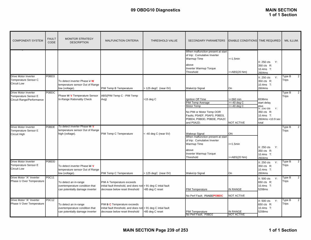
COMPONENT/ SYSTEM FAULT CODE
MONITOR STRATEGY DESCRIPTION MALFUNCTION CRITERIA THRESHOLD VALUE SECONDARY PARAMETERS ENABLE CONDITIONS TIME REQUIRED MIL ILLUM.
MCP A Ph C Di i When malfunction present at start of trip: Cumulative Inverter Warmup Time >=1.5min
aboveInverter Warmup Torque Threshold >=ABS(20 Nm)
Drive Motor Inverter Temperature Sensor C Circuit Low
P0BD3
To detect inverter Phase V W temperature sensor Out of Range low (voltage). PIM Temp B Temperature > 125 degC (near 0V) WakeUp Signal On
X: 250 cts Y: 350 cts R: 10.4ms T: 2604ms
Type B 2 Trips
Phase W V Temperature Sensor In-Range Rationality Check
ABS(PIM Temp C - PIM Temp Avg) >15 deg C Ignition Off Time >=360 min 8336ms
PIM Temp Average >=-40 deg C start delayMotor Temp >=-40 deg C plus
No PIM or Motor Temp OOR Faults; P0AEF, P0AF0, P0BD3, P0BD4, P0BDD, P0BDE, P0A2C and P0A2D. NOT ACTIVE
X: 250 cts Y: 350 cts R: 10.4ms T: 2604ms =10.9 sec total
To detect inverter Phase W V temperature sensor Out of Range high (voltage). PIM Temp C Temperature < -40 deg C (near 5V) Wakeup Signal ON
When malfunction present at start of trip: Cumulative Inverter Warmup Time >=1.5min
aboveInverter Warmup Torque Threshold >=ABS(20 Nm)
Drive Motor Inverter Temperature Sensor E Circuit Low
P0BDDTo detect inverter Phase W V temperature sensor Out of Range low (voltage). PIM Temp C Temperature > 125 degC (near 0V) WakeUp Signal On
X: 250 cts Y: 350 cts R: 10.4ms T: 2604ms
Type B 2 Trips
Drive Motor "A" Inverter Phase U Over Temperature
P0C11
To detect an in-range overtemperature condition that can potentially damage inverter
PIM A Temperature exceeds initial fault threshold, and does not decrease below reset threshold
> 91 deg C intial fault>85 deg C reset PIM Temperature IN RANGE
X: 500 cts Y: 650 cts R: 10.4ms T: 5208ms
No Perf Fault; P0AEEPOBDC NOT ACTIVEDrive Motor "A" Inverter Phase V Over Temperature
P0C12To detect an in-range overtemperature condition that can potentially damage inverter
PIM B C Temperature exceeds initial fault threshold, and does not decrease below reset threshold
> 91 deg C intial fault>85 deg C reset PIM Temperature IN RANGE
X: 500 cts Y: 650 cts R: 10.4ms T: 5208ms
No Perf Fault; P0BD2 NOT ACTIVE
P0BDC
Type B 2 Trips
Drive Motor Inverter Temperature Sensor E Circuit High
Type B 2 Trips
Type B 2 Trips
P0BDE
g
Type B 2 Trips
Drive Motor Inverter Temperature Sensor E Circuit Range/Performance
X: 250 cts Y: 350 cts R: 10.4ms T: 2604ms
X: 250 cts Y: 350 cts R: 10.4ms T: 2604ms
09 OBDG10 Diagnostics MAIN SECTION1 of 1 Section
MAIN SECTION Page 239 of 253 1 of 1 Section

COMPONENT/ SYSTEM FAULT CODE
MONITOR STRATEGY DESCRIPTION MALFUNCTION CRITERIA THRESHOLD VALUE SECONDARY PARAMETERS ENABLE CONDITIONS TIME REQUIRED MIL ILLUM.
MCP A Ph C Di iDrive Motor "A" Inverter Phase W Over Temperature
P0C13To detect an in-range overtemperature condition that can potentially damage inverter
PIM C B Temperature exceeds initial fault threshold, and does not decrease below reset threshold
> 91 deg C intial fault>85 deg C reset PIM Temperature IN RANGE
X: 500 cts Y: 650 cts R: 10.4ms T: 5208ms
No Perf Fault; P0BDC NOT ACTIVE
Drive Motor "A" Position Sensor Circuit
P0A3F
To detect Loss of Signal or converter error ( line open, short) in the Motor Resolver circuit Sin or Cos Signal <2.3V
Resolver Initialization Delay
Run/Crank Voltage OR Powertrain Relay Voltage
500ms
> 9.5 Volts OR < 18 Volts
X: 140 cts Y: 165 cts R: 0.083 - 0.5 ms T: 11.62 - 70.0 ms
Type A 1 Trip
Drive Motor "A" Position Sensor Circuit Range/Performance
P0A40To detect a Degradation of Signal fault in the angle data read by the Motor Resolver circuit. Sin or Cos Signal >4.0V Resolver Initialization Delay 500ms
X: 140 cts Y: 165 cts R: 0.083 - 0.5 ms T: 11.62 - 70.0 ms
Type A 1 Trip
Drive Motor "A" Position Sensor Circuit Loss of Tracking
P1B03
To detect a Loss of Tracking fault in the Motor Resolver circuit. Internal Tracking Error > 5 deg Resolver Initialization Delay 500ms
X: 140 cts Y: 165 cts R: 0.083 - 0.5 ms T: 11.62 - 70.0 ms
Type A 1 Trip
Drive Motor "A" Position Sensor Circuit Overspeed
P1B0D To detect when Motor A has exceeded operational maximum speed
ABS(Motor speed) initially AND then ABS(Motor Speed)
>11500 rpm>10000 rpm Wakeup Signal On
X: 10 cts Y: 15 cts R: 10.4ms T: 104ms
Type A 1 Trip
To detect an unvalidated Resolver Offset Learn Value and No Stored Previously Valid Value
Offset Learn DIDN'T complete because: ABS(Motor RPM Speed) >50 rpm Key Off TRUEOR:Filtered DC Voltage < 192 V Wakeup Signal ON
AND OR ALL Phase Curr Max-Min Delta <15 A ABS(Motor RPM Speed) < 20 rpmFor Time Period > 5ms 20% of 0.3s Valid Stored Offset FALSEOR:Offset Learn Completes ANDABS(Offset Correction Angle) > 25 deg
Drive Motor "A" Position Sensor Circuit "A" Low
P0C52To detect Resolver Circuit S1/3 Out of Range Low
Resolver S13 Circuit Reference Voltage < 0.5 v Wakeup Signal On
X: 50 cts Y: 80 cts R: 10.4ms T: 521ms
Type A 1 Trip
Drive Motor "A" Position Sensor Circuit "A" High
P0C53To detect Resolver Circuit S1/3 Out of Range High
Resolver S13 Circuit Reference Voltage > 3.0 v Wakeup Signal On
X: 20 cts Y: 30 cts R: 10.4ms T: 208ms
Type A 1 Trip
Drive Motor "A" Position Sensor Circuit "B" Low
P0C5CTo detect Resolver Circuit S2/4 Out of Range Low
Resolver S24 Circuit Reference Voltage < 0.5 v Wakeup Signal On
X: 50 cts Y: 80 cts R: 10.4ms T: 521ms
Type A 1 Trip
P0C17
Motor A Resolver Sensors - Discrete
Drive Motor "A" Position Sensor Not Learned
Type B 2 Trips
Motor A Resolver Sensors - Circuit
Type B 2 Trips
X: 1 ct Y: N/A R: 10.4ms T: 10.4ms
09 OBDG10 Diagnostics MAIN SECTION1 of 1 Section
MAIN SECTION Page 240 of 253 1 of 1 Section

COMPONENT/ SYSTEM FAULT CODE
MONITOR STRATEGY DESCRIPTION MALFUNCTION CRITERIA THRESHOLD VALUE SECONDARY PARAMETERS ENABLE CONDITIONS TIME REQUIRED MIL ILLUM.
MCP A Ph C Di iDrive Motor "A" Position Sensor Circuit "B" High
P0C5DTo detect Resolver Circuit S2/4 Out of Range High
Resolver S24 Circuit Reference Voltage > 3.0 v Wakeup Signal On
X: 20 cts Y: 30 cts R: 10.4ms T: 208ms
Type A 1 Trip
Drive Motor "A" Control Module Crankshaft Position Sensor Circuit
P1AC6
Detects Lack of Response from 58X Crank Sensor Crank Synchronization NO ACTIVITY Wakeup Signal On
X: 200 cts Y: 300 cts R: 10.4ms T: 2083ms
Type B 2 Trips
Detects Invalid 58X Crank Sensor Signal CPC Signal NOT VALID Engine Movment Detected > 5rpm
OR Edges Seen > 0
Current threshold: 75 A 48 fail counts out of 60 sample countsExecutes in a 2.08ms loop
Threshold time: 100ms Detects in 100msFail Case 2: Static Variable test Verify the calculated check sum
(CRC) is not equal to previous saved check sum (CRC)
Ignition switch in crank or run 2.08 ms loop
Fail Case 3: Monitor torque command by checking the SPI communication status
SPI rolling count fails to update more than threshold time
Threshold time: 90msec Ignition switch in crank or run 45 fail counts out of 50 sample countsDetects in 90ms2.08 ms loop
Current threshold: 10 A to 80 A (function of motor speed.);
Time threshold: 200 msTorque threshold:
86.18 Nm
Time threshold:
200 ms
Torque threshold:
86.18 Nm
Time threshold:
200 ms
Torque threshold:
Drive Motor "A" Control Module Crankshaft Position Sensor Performance
P1AC7 Type B 2 Trips
MCP power stage
Type A 1 Trip
in crank or run
MCP power stage Active
Ignition switch
Fail Case 1: Test of three phase current correlation
The sum of three phase currents is higher than current threshold during more than threshold time
DC current fails to show correct sign and magnitude more than current threshold during more than threshold time
Type A 1 Trip
Ignition switch in crank or run
MCP power stage Active 96 fail counts out of 120 sample countsDetects in 200ms2.08 ms loop
96 fail counts out of 120 sample countsDetects in 200ms2.08 ms loop
96 fail counts out f 120 l
Drive Motor A Torque Delivered Performance
The absolute error between calculated motor torque achieved and motor torque command is higher than torque threshold during more than threshold time
Fail Case 6: Check the Task1 reported motor torque achieved vs. torque command
The absolute error between Task1 reported motor torque achieved and motor torque command is higher than torque threshold during more than threshold time
Fail Case 7: Check the secured l l t d th h h t
The absolute error between d l l t d th h
Fail Case 5: Check the secured motor torque achieved error with respect to torque command
Motor 3-phase short
Torque Security Faults
X: 700 cts Y: 800 cts R: 10.4ms T: 7294ms
P0C19
P0C19
Drive Motor A Torque Delivered Performance
Fail Case 4: Check the DC current flow direction with respect to torque command/motor speed
96 fail counts out of 120 sample countsDetects in 200ms2.08 ms loop
Motor A Crank Pulse Faults
09 OBDG10 Diagnostics MAIN SECTION1 of 1 Section
MAIN SECTION Page 241 of 253 1 of 1 Section
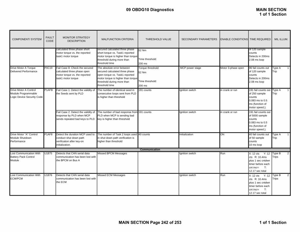
COMPONENT/ SYSTEM FAULT CODE
MONITOR STRATEGY DESCRIPTION MALFUNCTION CRITERIA THRESHOLD VALUE SECONDARY PARAMETERS ENABLE CONDITIONS TIME REQUIRED MIL ILLUM.
MCP A Ph C Di i52 Nm
Time threshold:
200 ms
Torque threshold:
52 Nm
Time threshold:
200 ms
Fail Case 1: Detect the validity of the Seeds sent by PLD
The number of identical seed in consecutive loops sent from PLD is higher than threshold
191 counts Ignition switch in crank or run 191 fail counts out of 250 sample counts0.083 ms to 0.5 ms (function of motor speed.);
Fail Case 2: Detect the validity of response by PLD when MCP sends repeated bad keys to PLD
The number of bad response from PLD when MCP is sending bad key is higher than threshold
191 counts Ignition switch in crank or run 191 fail counts out of 5000 sample counts0.083 ms to 0.5 ms (function of motor speed.);
Drive Motor "A" Control Module Shutdown Performance
P1AF8 Detect the duration MCP used to conduct shut down path verification after key-on initialization.
The number of Task 2 loops used in shut down path verification is higher than threshold
40 counts Initialization ON 40 fail counts out of 50 sample counts10 ms loop
Type A 1 Trip
Lost Communication With Battery Pack Control Module
U1875 Detects that CAN serial data communication has been lost with the BPCM on Bus A
Missed BPCM Messages Ignition switch Run X: 12 cts Y: 12 cts R: 10.4ms plus 1 sec cntdwn timer before each cnt incr= T: 12.17 sec total
Type B 2 Trips
Lost Communication With ECM/PCM
U1876 Detects that CAN serial data communication has been lost with the ECM
Missed ECM Messages Ignition switch Run X: 12 cts Y: 12 cts R: 10.4ms plus 1 sec cntdwn timer before each cnt incr= T: 12.17 sec total
Type B 2 Trips
Type A 1 Trip
96 fail counts out of 120 sample countsDetects in 200ms2.08 ms loop
MCP power stage Motor 3-phase open Type A 1 Trip
Drive Motor A Control Module Programmable Logic Device Security Code
P1AFB
Drive Motor A Torque Delivered Performance
P0C19 Fail Case 8: Check the secured calculated three phase open motor torque vs. the reported task1 motor torque
The absolute error between secured calculated three phase open torque vs. Task1 reported motor torque is higher than torque threshold during more than threshold time
of 120 sample countsDetects in 200ms2.08 ms loop
calculated three phase short motor torque vs. the reported task1 motor torque
secured calculated three phase short torque vs. Task1 reported motor torque is higher than torque threshold during more than threshold time
Communication
09 OBDG10 Diagnostics MAIN SECTION1 of 1 Section
MAIN SECTION Page 242 of 253 1 of 1 Section

APPENDIXInverter Temperature Sensor Mapping Grid SAEDrive Motor A Phase U PIM_A PIM_0 A
Phase V PIM_B C PIM_2 C EPhase W PIM_C B PIM_1 E C
Drive Motor B Phase U PIM_A B PIM_1 B DPhase V PIM_B C PIM_2 D FPhase W PIM_C A PIM_0 F B
ALU=
Arithmetic Logic Unit
BPCM=
Batt Pack Ctrl Module
HWIO=
Hardware Input/Output
IGBT=
Insulated Gate Bipolar Transistors (Phase Current Controllers)
OOR=Out of Range
09 OBDG10 Diagnostics MAIN SECTION1 of 1 Section
MAIN SECTION Page 243 of 253 1 of 1 Section

COMPONENT/ SYSTEM FAULT CODE
MONITOR STRATEGY DESCRIPTION MALFUNCTION CRITERIA THRESHOLD VALUE SECONDARY PARAMETERS ENABLE CONDITIONS TIME REQUIRED MIL ILLUM.
To detect electrical failure of phase current sensor. Sum of 3 phase currents > 75 A Main Relay Closed
Wakeup Signal OnDrive Motor "B" Phase U-V-W Current Sensor Overcurrent
P0C04Fail Case 1: To detect fast, repeated 3 Phase over currents and to protect IGBT. Sets for fault occurrence rates of 50-100%
X: 5 1 cts Y: 10 cts R: 2.08ms T: 10.42.08ms
Fail Case 2: To detect slow, intermittent 3 Phase over current and to protect IGBT. Sets for fault occurrence rates of 10-40%. * Note: Min fault time for slow loop at 40% is 20 fail counts in 47 samples, or 97.9ms. Any faster and fast loop in Case 1 sets first.
X: 20 4cts Y: 200 50cts R: 2.08ms T: 97.9 8.32ms min* (see Note)
Drive Motor "B" Phase U-V-W Circuit/Open
P0C08 Drive Motor "B" Missing Motor Current
U, V, or W Phase current sensor Two Non-Peak Phase Sensors are BOTH AND THEN
> ABS (9 A)
Wakeup Signal Inverter State Inverter Voltage
On RUN > 35 V
2 Task1 Loops = 4.2 ms PLUS
Type A 1 Trip
Checks for minimum current in each phase when rotor position is near that peak's phase axis. Each phase is checked individually as rotor turns.
Phase Axis Current < ABS (9 A)
Rotor Position -30 deg < Phase Axis < +30 deg
X: 201 cts Y: N/A R: 0.083 - 0.5 ms T: 16.7 - 101 ms
Peak Phase Current >= 23 A20.8 - 104.7 ms TOTAL
Circuit Low monitor to detect the failure of U-phase current sensor circuit below valid range
U Phase current sensor output at highside < -700 A Wakeup Signal On
PWMOutputEnable FALSE
Circuit High monitor to detect the failure of U-phase current sensor circuit above valid range
U Phase current sensor output at highside > 700 A Wakeup Signal On
PWMOutputEnable FALSEOffset Circuit monitor to detect the failure of U-phase offset current above valid range
U Phase offset current output at highside >30 A Wakeup Signal On
Power Stage OPENP0BF3/P0BF4 NOT ACTIVE
Circuit Low monitor to detect the failure of V-phase current sensor circuit below valid range
V Phase current sensor output at highside < -700 A Wakeup Signal On
PWMOutputEnable FALSE
Drive Motor "B" Phase U Current Sensor Offset Out-of Range
P0BF2 Type B 2 TripsX: 100 cts
Y: N/A R: 2.08ms T: 208ms
Drive Motor "B" Phase U-V-W Correlation
P0BFE Type A 1 Trip
X: 7 cts Y: 10 cts R: 0.083 - 0.5 ms
Drive Motor "B" Phase U Current Sensor Circuit High
P0BF4 Type B 2 Trips
Wakeup Signal On
P0BF3
U, V, or W Phase current sensor > 680 600A
Drive Motor "B" Phase U Current Sensor Circuit Low
Type B 2 Trips
Drive Motor "B" Phase V Current Sensor Circuit Low
P0BF7 Type B 2 Trips
MCP B Phase Current Diagnostics:
X: 10 cts Y: 15 cts R: 2.08ms T: 20.8ms
X: 10 cts Y: 15 cts R: 2.08ms T: 20.8ms
X: 10 cts Y: 15 cts R: 2.08ms T: 20.8ms
Type A 1 Trip
09 OBDG10 Diagnostics MAIN SECTION1 of 1 Section
MAIN SECTION Page 244 of 253 1 of 1 Section

COMPONENT/ SYSTEM FAULT CODE
MONITOR STRATEGY DESCRIPTION MALFUNCTION CRITERIA THRESHOLD VALUE SECONDARY PARAMETERS ENABLE CONDITIONS TIME REQUIRED MIL ILLUM.
Circuit High monitor to detect the failure of V-phase current sensor circuit above valid range
V Phase current sensor output current at highside > 700 A Wakeup Signal On
PWMOutputEnable FALSEOffset Circuit monitor to detect the failure of U-phase offset current above valid range
U Phase offset current output at highside >30 A Wakeup Signal On
Power Stage OPENP0BF7/P0BF8 NOT ACTIVE
Circuit Low monitor to detect the failure of W-phase current sensor circuit below valid range
W Phase current sensor output at highside < -700 A Wakeup Signal On
PWMOutputEnable FALSE
Circuit High monitor to detect the failure of W-phase current sensor circuit above valid range
W Phase current sensor output at highside > 700 A Wakeup Signal On
PWMOutputEnable FALSEOffset Circuit monitor to detect the failure of U-phase offset current above valid range
U Phase offset current output at highside >30 A Wakeup Signal On
Power Stage OPEN P0BFB/P0BFC NOT ACTIVE
Drive Motor "B" Inverter Performance
P0A79
Detects IGBT Desaturation FaultsPhase A, B, or C High or Low Side Devices OVERDRIVEN (Status Fault Bit) Wakeup Signal On
X: 1 ct Y: N/A R: 2.08ms T: 2.08ms
Type A 1 Trip
Drive Motor "B" Inverter Power Supply Circuit/Open
P0C0E
Detects IGBT Bias Faults Phase A, B , or C Power Supply FAILED (Status Fault Bit)
Inverter State
Run/Crank Voltage OR Powertrain Relay Voltage
Initialization Complete
> 9.5 Volts OR < 18 Volts
X: 1 ct Y: N/A R: 2.08ms T: 2.08ms
Type A 1 Trip
Drive Motor "B" Hybrid Battery System Voltage High
P1AEF
To detect over voltage and to protect TPIM Vdc Circuit HV Sensor Voltage > 475V WakeUp Signal On
X: 5 cts Y: N/A R: 0.083 - 0.5 ms T: 0.42 - 2.50 ms
Type A 1 Trip
Drive Motor "B" Control Module Hybrid Battery Voltage Sense Circuit Low Voltage
P1AEA
Circuit Low monitor to detect the failure of HV output voltage sensor circuit below valid range HV Sensor Voltage <0V Inverter State Initialization Complete
X: 50 70cts Y: 100 cts R: 2.08ms T: 104 146 ms
Type B 2 Trips
Drive Motor "B" Control Module Hybrid Battery Voltage Sense Circuit High Voltage
P1AEB
Circuit High monitor to detect the failure of HV output voltage sensor circuit above valid range HV Sensor Voltage >564 500V Inverter State Initialization Complete
X: 50 cts Y: 100 cts R: 2.08ms T: 104ms
Type B 2 Trips
X: 10 cts Y: 15 cts R: 2.08ms T: 20.8ms
X: 100 cts Y: N/A R: 2.08ms T: 208ms
Drive Motor "B" Phase V Current Sensor Circuit High
P0BF8 Type B 2 TripsX: 10 cts
Y: 15 cts R: 2.08ms T: 20.8ms
X: 10 cts Y: 15 cts R: 2.08ms T: 20.8ms
Drive Motor "B" Phase V Current Sensor Offset Out-of Range
P0BF6 Type B 2 Trips
Drive Motor "B" Phase W Current Sensor Circuit High
P0BFC Type B 2 Trips
Drive Motor "B" Phase W Current Sensor Circuit Low
P0BFB Type B 2 Trips
Drive Motor "B" Phase W Current Sensor Offset Out-of Range
P0BFA Type B 2 TripsX: 100 cts
Y: N/A R: 2.08ms T: 208ms
MCP B IGBT Diagnostics
MCP B High Voltage (HV) Diagnostics:
09 OBDG10 Diagnostics MAIN SECTION1 of 1 Section
MAIN SECTION Page 245 of 253 1 of 1 Section

COMPONENT/ SYSTEM FAULT CODE
MONITOR STRATEGY DESCRIPTION MALFUNCTION CRITERIA THRESHOLD VALUE SECONDARY PARAMETERS ENABLE CONDITIONS TIME REQUIRED MIL ILLUM.
To check correlation of HV_MCP with HV_Midpack and HV_Battery Voltages.
ABS(MCP HV voltage - HV Battery voltage) >= 34 V WakeUp signal ONOR ANDABS(MCP HV voltage - MidPack voltage) >= 90 V
To detect interlock circuit open. HV Interlock Status Discrete Input TRUE WakeUp Signal On 250ms +HV CAN Msg Rx TRUEBPCM Sourcing MCP HVILStatus TRUE
Isolation Lost between Battery Pack and Chassis
Isolation Ratio (MidPack Voltage / HV Battery Voltage) < 0.27 OR >1.80
No HV Clamp Fault or MidPack Sensor OOR Faults; P1AEF, P1AF6, and P1AF7 NOT ACTIVE
X: 450 cts Y: 500 cts R: 10.4ms T: 4689ms
HV Sensor Voltage > 50VDrive Motor "B" Control Module Hybrid Battery Voltage Isolation Sensor Circuit Low
P1AF6
Circuit Low monitor to detect the failure of HV MidPack voltage sensor circuit below valid range MidPack Voltage <0V Inverter State Initialization Complete
X: 70 cts Y: 100 cts R: 10.4ms T: 729ms
Type B 2 Trips
Drive Motor "B" Control Module Hybrid Battery Voltage Isolation Sensor Circuit High
P1AF7
Circuit High monitor to detect the failure of HV MidPack voltage sensor circuit above valid range MidPack Voltage >564 500V Inverter State Initialization Complete
X: 50 cts Y: 100 cts R: 10.4ms T: 521ms
Type B 2 Trips
Motor B Temperature Sensor In-Range Rationality Check
ABS(Motor Temp - PIM Temp Avg) > 28deg C Ignition Off Time >=360 min 8336ms
PIM Temp Average >=-40 deg C start delayMotor Temp >=-40 deg C plus
No PIM or Motor Temp OOR Faults; P0AF4, P0AF5, P0BD8, P0BD9, P0BE2, P0BE3, P0A32 and P0A33. NOT ACTIVE
X: 250 cts Y: 350 cts R: 10.4ms T: 2604ms =10.9 sec total
To detect temperature sensor Out of Range high (voltage). Motor Temperature < -40 deg C (near 5V) Wakeup Signal On
When malfunction present at start of trip: Cumulative Motor Warmup Time >=1.5min
aboveMotor Warmup Torque Threshold >=ABS(20 Nm)
Drive Motor "B" Control Module Temperature Sensor Circuit Out of Range Low
P0A32
To detect temperature sensor Out of Range low (voltage). Motor Temperature > 230 degC (near 0V) WakeUp Signal On
X: 250 cts Y: 350 cts R: 10.4ms T: 2604ms
Type B 2 Trips
X: 18 cts Y: 30 cts R: 10.4ms T: 187ms
90 P1AED Type A 1 Trip
Type B 2 Trips
P0A31Drive Motor "B" Control Module Temperature Sensor Performance
X: 900 cts Y:1800cts R: 10.4ms T: 9378ms
P1B06 Special Type C No Mil
X: 10 cts Y: 14 cts R: 10.4ms
Drive Motor "B" Control Module Temperature Sensor Circuit Out of Range High
P0A33 Type B 2 Trips
P1AF2
Motor B Temperature Sensor
Drive Motor "B" Control Module Hybrid Battery Voltage System Isolation Fault
Special Type C No Mil
Drive Motor "B" HV Interlock (HVIL) Break Detected
09 OBDG10 Diagnostics MAIN SECTION1 of 1 Section
MAIN SECTION Page 246 of 253 1 of 1 Section
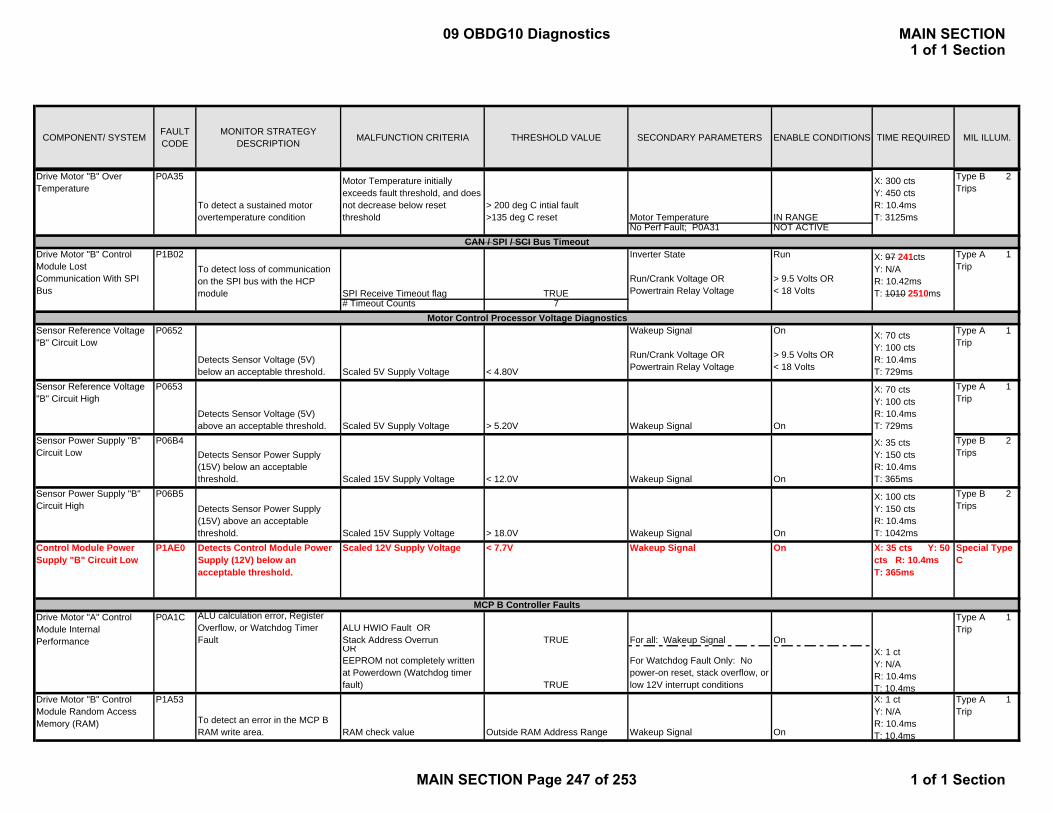
COMPONENT/ SYSTEM FAULT CODE
MONITOR STRATEGY DESCRIPTION MALFUNCTION CRITERIA THRESHOLD VALUE SECONDARY PARAMETERS ENABLE CONDITIONS TIME REQUIRED MIL ILLUM.
Drive Motor "B" Over Temperature
P0A35
To detect a sustained motor overtemperature condition
Motor Temperature initially exceeds fault threshold, and does not decrease below reset threshold
> 200 deg C intial fault>135 deg C reset Motor Temperature IN RANGE
X: 300 cts Y: 450 cts R: 10.4ms T: 3125ms
No Perf Fault; P0A31 NOT ACTIVE
To detect loss of communication on the SPI bus with the HCP module SPI Receive Timeout flag TRUE
Inverter State
Run/Crank Voltage OR Powertrain Relay Voltage
Run
> 9.5 Volts OR < 18 Volts
X: 97 241cts Y: N/A R: 10.42ms T: 1010 2510ms
# Timeout Counts 7
Sensor Reference Voltage "B" Circuit Low
P0652
Detects Sensor Voltage (5V) below an acceptable threshold. Scaled 5V Supply Voltage < 4.80V
Wakeup Signal
Run/Crank Voltage OR Powertrain Relay Voltage
On
> 9.5 Volts OR < 18 Volts
X: 70 cts Y: 100 cts R: 10.4ms T: 729ms
Type A 1 Trip
Sensor Reference Voltage "B" Circuit High
P0653
Detects Sensor Voltage (5V) above an acceptable threshold. Scaled 5V Supply Voltage > 5.20V Wakeup Signal On
X: 70 cts Y: 100 cts R: 10.4ms T: 729ms
Type A 1 Trip
Sensor Power Supply "B" Circuit Low
P06B4Detects Sensor Power Supply (15V) below an acceptable threshold. Scaled 15V Supply Voltage < 12.0V Wakeup Signal On
X: 35 cts Y: 150 cts R: 10.4ms T: 365ms
Type B 2 Trips
Sensor Power Supply "B" Circuit High
P06B5Detects Sensor Power Supply (15V) above an acceptable threshold. Scaled 15V Supply Voltage > 18.0V Wakeup Signal On
X: 100 cts Y: 150 cts R: 10.4ms T: 1042ms
Type B 2 Trips
Control Module Power Supply "B" Circuit Low
P1AE0 Detects Control Module Power Supply (12V) below an acceptable threshold.
Scaled 12V Supply Voltage < 7.7V Wakeup Signal On X: 35 cts Y: 50 cts R: 10.4ms T: 365ms
Special Type C
ALU calculation error, Register Overflow, or Watchdog Timer Fault
ALU HWIO Fault OR Stack Address Overrun TRUE For all: Wakeup Signal OnOR EEPROM not completely written at Powerdown (Watchdog timer fault) TRUE
For Watchdog Fault Only: No power-on reset, stack overflow, or low 12V interrupt conditions
X: 1 ct Y: N/A R: 10.4ms T: 10.4ms
Drive Motor "B" Control Module Random Access Memory (RAM)
P1A53
To detect an error in the MCP B RAM write area. RAM check value Outside RAM Address Range Wakeup Signal On
X: 1 ct Y: N/A R: 10.4ms T: 10.4ms
Type A 1 Trip
Type A 1 Trip
Drive Motor "B" Control Module Lost Communication With SPI Bus
P1B02
Type A 1 Trip
P0A1CDrive Motor "A" Control Module Internal Performance
Type B 2 Trips
CAN / SPI / SCI Bus Timeout
Motor Control Processor Voltage Diagnostics
MCP B Controller Faults
09 OBDG10 Diagnostics MAIN SECTION1 of 1 Section
MAIN SECTION Page 247 of 253 1 of 1 Section

COMPONENT/ SYSTEM FAULT CODE
MONITOR STRATEGY DESCRIPTION MALFUNCTION CRITERIA THRESHOLD VALUE SECONDARY PARAMETERS ENABLE CONDITIONS TIME REQUIRED MIL ILLUM.
Drive Motor "B" Control Module Read Only Memory (ROM)
P1A54To detect an error in the MCP B ROM using a checksum calculation FlashCellError TRUE Wakeup Signal On
X: 1 ct Y: N/A R: 10.4ms T: 10.4ms
Type A 1 Trip
Drive Motor "B" Control Module EEPROM Error
P1ADD
Detects mismatch between Flash and EEPROM Power Off Levels EEpromCellStatus TRUE Wakeup Signal On
X: 1 ct Y: N/A R: 10.4ms T: 10.4ms
Type A 1 Trip
Drive Motor "B" Control Module Not Programmed
P1A52Drive Motor "B" Control Module Programmed with Test Code, or Motor A calibration (via Cal ID)
Calibration contains Test code identifier or Motor A Identifier TRUE Always
X: 1 ct Y: N/A R: 10.4ms T: 10.4ms
Type A 1 Trip
Phase U W Temperature Sensor In-Range Rationality Check
ABS(PIM Temp A - PIM Temp Avg) >15 deg C Ignition Off Time >=360 min 8336ms
PIM Temp Average >=-40 deg C start delayMotor Temp >=-40 deg C plus
No PIM or Motor Temp OOR Faults; P0AF4, P0AF5, P0BD8, P0BD9, P0BE2, P0BE3, P0A32 and P0A33. NOT ACTIVE
X: 250 cts Y: 350 cts R: 10.4ms T: 2604ms =10.9 sec total
To detect inverter Phase U W temperature sensor Out of Range high (voltage). PIM Temp A Temperature < -40 deg C (near 5V) Wakeup Signal ON
When malfunction present at start of trip: Cumulative Inverter Warmup Time >=1.5min
X: 250 cts Y: 350 cts R: 10.4ms T: 2604ms =10.9 sec total
aboveInverter Warmup Torque Threshold >=ABS(20 Nm)
Drive Motor Inverter Temperature Sensor B Circuit Low
P0AF4
To detect inverter Phase U W temperature sensor Out of Range low (voltage). PIM Temp A Temperature > 125 degC (near 0V) WakeUp Signal On
X: 250 cts Y: 350 cts R: 10.4ms T: 2604ms =10.9 sec total
Type B 2 Trips
Phase V U Temperature Sensor In-Range Rationality Check
ABS(PIM Temp B - PIM Temp Avg) >15 deg C Ignition Off Time >=360 min 8336ms
PIM Temp Average >=-40 deg C start delayMotor Temp >=-40 deg C plus
Drive Motor Inverter Temperature Sensor B Circuit Range/Performance
P0AF3 Type B 2 Trips
Type B 2 Trips
P0AF5Drive Motor Inverter Temperature Sensor B Circuit High
Type B 2 Trips
Motor B Inverter Temperature Sensors
Drive Motor Inverter Temperature Sensor D Circuit Range/Performance
P0BD7
MCP B Not Programmed
09 OBDG10 Diagnostics MAIN SECTION1 of 1 Section
MAIN SECTION Page 248 of 253 1 of 1 Section

COMPONENT/ SYSTEM FAULT CODE
MONITOR STRATEGY DESCRIPTION MALFUNCTION CRITERIA THRESHOLD VALUE SECONDARY PARAMETERS ENABLE CONDITIONS TIME REQUIRED MIL ILLUM.
No PIM or Motor Temp OOR Faults; P0AF4, P0AF5. P0BD8, P0BD9, P0BE2, P0BD3, P0A32 or P0A33. NOT ACTIVE
X: 250 cts Y: 350 cts R: 10.4ms T: 2604ms =10.9 sec total
To detect inverter Phase V U temperature sensor Out of Range high (voltage). PIM Temp B Temperature < -40 deg C (near 5V) Wakeup Signal ON
When malfunction present at start of trip: Cumulative Inverter Warmup Time >=1.5min
aboveInverter Warmup Torque Threshold >=ABS(20 Nm)
Drive Motor Inverter Temperature Sensor D Circuit Low
P0BD8
To detect inverter Phase V U temperature sensor Out of Range low (voltage). PIM Temp B Temperature > 125 degC (near 0V) WakeUp Signal On
X: 250 cts Y: 350 cts R: 10.4ms T: 2604ms =10.9 sec total
Type B 2 Trips
Phase W V Temperature Sensor In-Range Rationality Check
ABS(PIM Temp C - PIM Temp Avg) >15 deg C Ignition Off Time >=360 min 8336ms
PIM Temp Average >=-40 deg C start delayMotor Temp >=-40 deg C plus
No PIM or Motor Temp OOR Faults; P0AF4, P0AF5, P0BD8, P0BD9, P0BE2, P0BE3, P0A32 and P0A33. NOT ACTIVE
X: 250 cts Y: 350 cts R: 10.4ms T: 2604ms =10.9 sec total
To detect inverter Phase W V temperature sensor Out of Range high (voltage). PIM Temp C Temperature < -40 deg C (near 5V) Wakeup Signal ON
When malfunction present at start of trip: Cumulative Inverter Warmup Time >=1.5min
aboveInverter Warmup Torque Threshold >=ABS(20 Nm)
Drive Motor Inverter Temperature Sensor F Circuit Low
P0BE2
To detect inverter Phase W V temperature sensor Out of Range low (voltage). PIM Temp C Temperature > 125 degC (near 0V) WakeUp Signal On
X: 250 cts Y: 350 cts R: 10.4ms T: 2604ms =10.9 sec total
Type B 2 Trips
Drive Motor "B" Inverter Phase U Over Temperature
P0C14To detect an in-range overtemperature condition that can potentially damage inverter
PIM A B Temperature exceeds initial fault threshold, and does not decrease below reset threshold
> 91 deg C intial fault>85 deg C reset PIM Temperature IN RANGE
X: 500 cts Y: 650 cts R: 10.4ms T: 5208ms
Type B 2 Trips
No Perf Fault; P0BD7 NOT ACTIVE
X: 250 cts Y: 350 cts R: 10.4ms T: 2604ms =10.9 sec total
Type B 2 Trips
X: 250 cts Y: 350 cts R: 10.4ms T: 2604ms =10.9 sec total
Drive Motor Inverter Temperature Sensor D Circuit High
P0BE1Drive Motor Inverter Temperature Sensor F Circuit Range/Performance
P0BD9
Drive Motor Inverter Temperature Sensor F Circuit High
P0BE3 Type B 2 Trips
Type B 2 Trips
09 OBDG10 Diagnostics MAIN SECTION1 of 1 Section
MAIN SECTION Page 249 of 253 1 of 1 Section
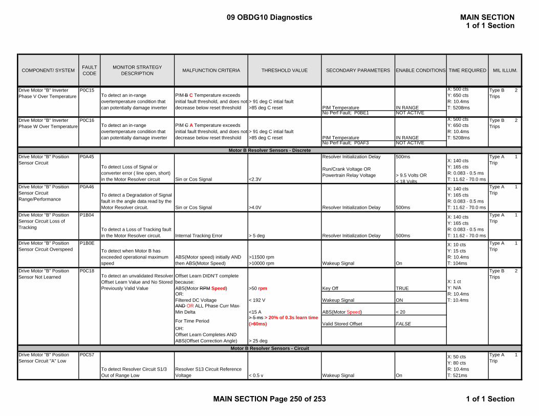
COMPONENT/ SYSTEM FAULT CODE
MONITOR STRATEGY DESCRIPTION MALFUNCTION CRITERIA THRESHOLD VALUE SECONDARY PARAMETERS ENABLE CONDITIONS TIME REQUIRED MIL ILLUM.
Drive Motor "B" Inverter Phase V Over Temperature
P0C15To detect an in-range overtemperature condition that can potentially damage inverter
PIM B C Temperature exceeds initial fault threshold, and does not decrease below reset threshold
> 91 deg C intial fault>85 deg C reset PIM Temperature IN RANGE
X: 500 cts Y: 650 cts R: 10.4ms T: 5208ms
Type B 2 Trips
No Perf Fault; P0BE1 NOT ACTIVEDrive Motor "B" Inverter Phase W Over Temperature
P0C16To detect an in-range overtemperature condition that can potentially damage inverter
PIM C A Temperature exceeds initial fault threshold, and does not decrease below reset threshold
> 91 deg C intial fault>85 deg C reset PIM Temperature IN RANGE
X: 500 cts Y: 650 cts R: 10.4ms T: 5208ms
Type B 2 Trips
No Perf Fault; P0AF3 NOT ACTIVE
Drive Motor "B" Position Sensor Circuit
P0A45
To detect Loss of Signal or converter error ( line open, short) in the Motor Resolver circuit Sin or Cos Signal <2.3V
Resolver Initialization Delay
Run/Crank Voltage OR Powertrain Relay Voltage
500ms
> 9.5 Volts OR < 18 Volts
X: 140 cts Y: 165 cts R: 0.083 - 0.5 ms T: 11.62 - 70.0 ms
Type A 1 Trip
Drive Motor "B" Position Sensor Circuit Range/Performance
P0A46
To detect a Degradation of Signal fault in the angle data read by the Motor Resolver circuit. Sin or Cos Signal >4.0V Resolver Initialization Delay 500ms
X: 140 cts Y: 165 cts R: 0.083 - 0.5 ms T: 11.62 - 70.0 ms
Type A 1 Trip
Drive Motor "B" Position Sensor Circuit Loss of Tracking
P1B04
To detect a Loss of Tracking fault in the Motor Resolver circuit. Internal Tracking Error > 5 deg Resolver Initialization Delay 500ms
X: 140 cts Y: 165 cts R: 0.083 - 0.5 ms T: 11.62 - 70.0 ms
Type A 1 Trip
Drive Motor "B" Position Sensor Circuit Overspeed
P1B0ETo detect when Motor B has exceeded operational maximum speed
ABS(Motor speed) initially AND then ABS(Motor Speed)
>11500 rpm>10000 rpm Wakeup Signal On
X: 10 cts Y: 15 cts R: 10.4ms T: 104ms
Type A 1 Trip
To detect an unvalidated Resolver Offset Learn Value and No Stored Previously Valid Value
Offset Learn DIDN'T complete because: ABS(Motor RPM Speed) >50 rpm Key Off TRUEOR:Filtered DC Voltage < 192 V Wakeup Signal ONAND OR ALL Phase Curr Max-Min Delta <15 A ABS(Motor Speed) < 20
For Time Period> 5 ms > 20% of 0.3s learn time (>60ms) Valid Stored Offset FALSE
OR:Offset Learn Completes ANDABS(Offset Correction Angle) > 25 deg
Drive Motor "B" Position Sensor Circuit "A" Low
P0C57
To detect Resolver Circuit S1/3 Out of Range Low
Resolver S13 Circuit Reference Voltage < 0.5 v Wakeup Signal On
X: 50 cts Y: 80 cts R: 10.4ms T: 521ms
Type A 1 Trip
Drive Motor "B" Position Sensor Not Learned
Type B 2 Trips
X: 1 ct Y: N/A R: 10.4ms T: 10.4ms
P0C18
Motor B Resolver Sensors - Discrete
Motor B Resolver Sensors - Circuit
09 OBDG10 Diagnostics MAIN SECTION1 of 1 Section
MAIN SECTION Page 250 of 253 1 of 1 Section
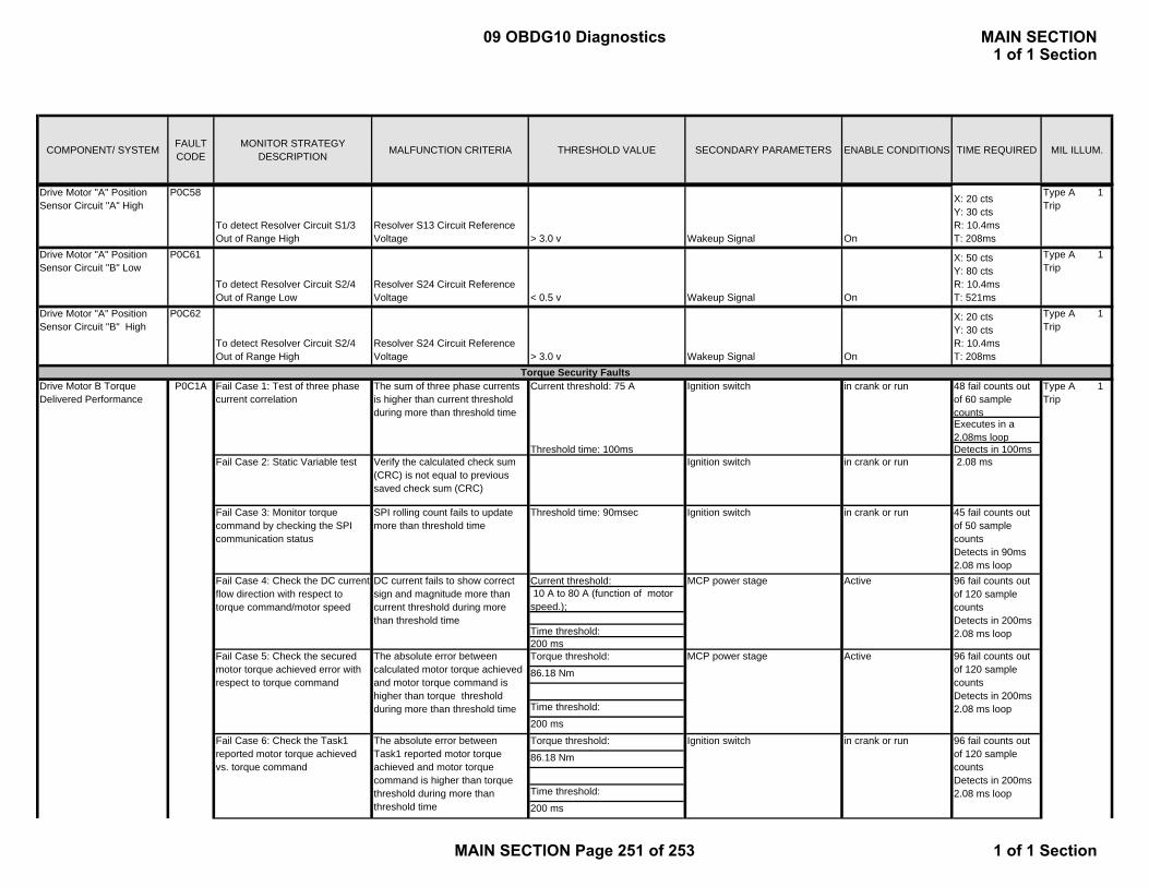
COMPONENT/ SYSTEM FAULT CODE
MONITOR STRATEGY DESCRIPTION MALFUNCTION CRITERIA THRESHOLD VALUE SECONDARY PARAMETERS ENABLE CONDITIONS TIME REQUIRED MIL ILLUM.
Drive Motor "A" Position Sensor Circuit "A" High
P0C58
To detect Resolver Circuit S1/3 Out of Range High
Resolver S13 Circuit Reference Voltage > 3.0 v Wakeup Signal On
X: 20 cts Y: 30 cts R: 10.4ms T: 208ms
Type A 1 Trip
Drive Motor "A" Position Sensor Circuit "B" Low
P0C61
To detect Resolver Circuit S2/4 Out of Range Low
Resolver S24 Circuit Reference Voltage < 0.5 v Wakeup Signal On
X: 50 cts Y: 80 cts R: 10.4ms T: 521ms
Type A 1 Trip
Drive Motor "A" Position Sensor Circuit "B" High
P0C62
To detect Resolver Circuit S2/4 Out of Range High
Resolver S24 Circuit Reference Voltage > 3.0 v Wakeup Signal On
X: 20 cts Y: 30 cts R: 10.4ms T: 208ms
Type A 1 Trip
Current threshold: 75 A 48 fail counts out of 60 sample countsExecutes in a 2.08ms loop
Threshold time: 100ms Detects in 100msFail Case 2: Static Variable test Verify the calculated check sum
(CRC) is not equal to previous saved check sum (CRC)
Ignition switch in crank or run 2.08 ms
Fail Case 3: Monitor torque command by checking the SPI communication status
SPI rolling count fails to update more than threshold time
Threshold time: 90msec Ignition switch in crank or run 45 fail counts out of 50 sample countsDetects in 90ms2.08 ms loop
Current threshold: 10 A to 80 A (function of motor speed.);
Time threshold: 200 msTorque threshold:
86.18 Nm
Time threshold:
200 ms
Torque threshold:
86.18 Nm
Time threshold:
200 ms
Ignition switch in crank or run 96 fail counts out of 120 sample countsDetects in 200ms2.08 ms loop
Type A 1 Trip
96 fail counts out of 120 sample countsDetects in 200ms2.08 ms loop
Fail Case 6: Check the Task1 reported motor torque achieved vs. torque command
The absolute error between Task1 reported motor torque achieved and motor torque command is higher than torque threshold during more than threshold time
in crank or runFail Case 1: Test of three phase current correlation
The sum of three phase currents is higher than current threshold during more than threshold time
MCP power stage Active
Drive Motor B Torque Delivered Performance
P0C1A
Active
Torque Security Faults
Fail Case 5: Check the secured motor torque achieved error with respect to torque command
The absolute error between calculated motor torque achieved and motor torque command is higher than torque threshold during more than threshold time
96 fail counts out of 120 sample countsDetects in 200ms2.08 ms loop
MCP power stage
Ignition switch
Fail Case 4: Check the DC current flow direction with respect to torque command/motor speed
DC current fails to show correct sign and magnitude more than current threshold during more than threshold time
09 OBDG10 Diagnostics MAIN SECTION1 of 1 Section
MAIN SECTION Page 251 of 253 1 of 1 Section
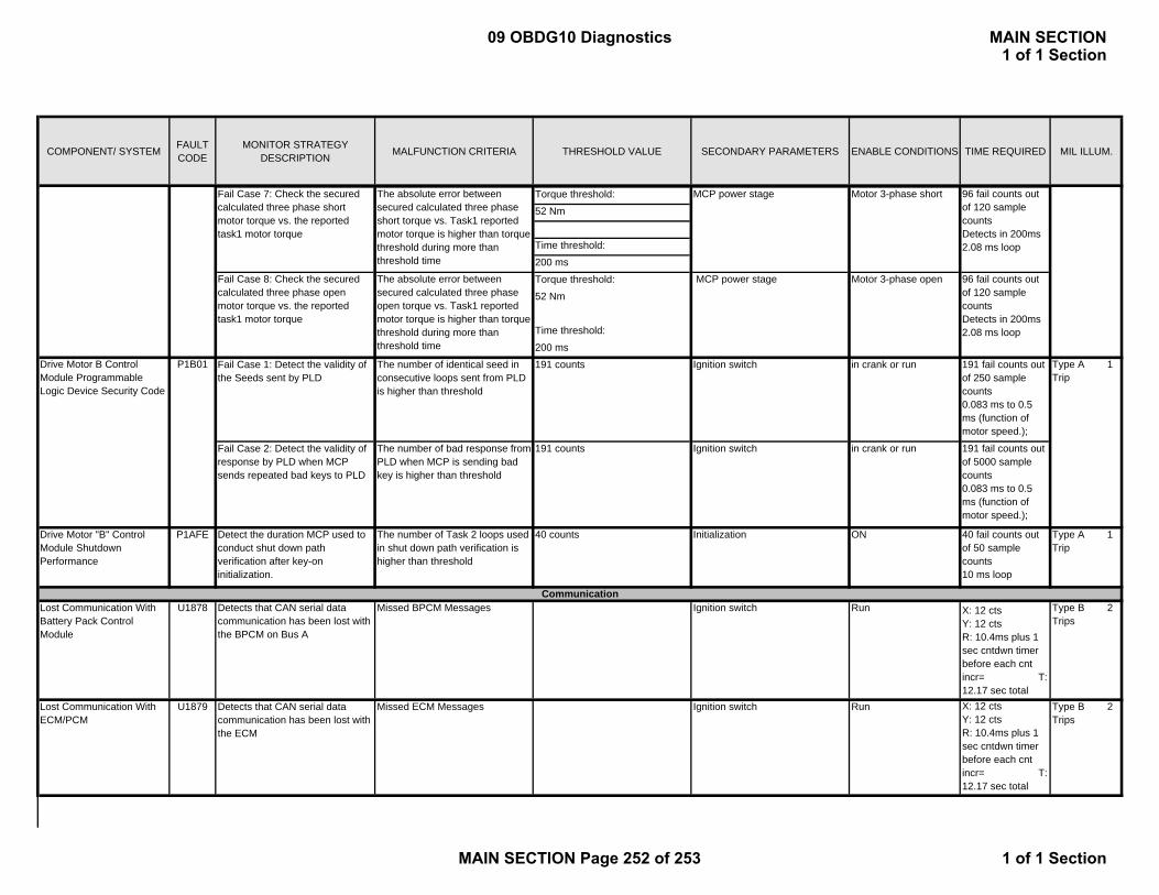
COMPONENT/ SYSTEM FAULT CODE
MONITOR STRATEGY DESCRIPTION MALFUNCTION CRITERIA THRESHOLD VALUE SECONDARY PARAMETERS ENABLE CONDITIONS TIME REQUIRED MIL ILLUM.
Torque threshold:
52 Nm
Time threshold:
200 ms
Torque threshold:
52 Nm
Time threshold:
200 ms
Fail Case 1: Detect the validity of the Seeds sent by PLD
The number of identical seed in consecutive loops sent from PLD is higher than threshold
191 counts Ignition switch in crank or run 191 fail counts out of 250 sample counts0.083 ms to 0.5 ms (function of motor speed.);
Fail Case 2: Detect the validity of response by PLD when MCP sends repeated bad keys to PLD
The number of bad response from PLD when MCP is sending bad key is higher than threshold
191 counts Ignition switch in crank or run 191 fail counts out of 5000 sample counts0.083 ms to 0.5 ms (function of motor speed.);
Drive Motor "B" Control Module Shutdown Performance
P1AFE Detect the duration MCP used to conduct shut down path verification after key-on initialization.
The number of Task 2 loops used in shut down path verification is higher than threshold
40 counts Initialization ON 40 fail counts out of 50 sample counts10 ms loop
Type A 1 Trip
Lost Communication With Battery Pack Control Module
U1878 Detects that CAN serial data communication has been lost with the BPCM on Bus A
Missed BPCM Messages Ignition switch Run X: 12 cts Y: 12 cts R: 10.4ms plus 1 sec cntdwn timer before each cnt incr= T: 12.17 sec total
Type B 2 Trips
Lost Communication With ECM/PCM
U1879 Detects that CAN serial data communication has been lost with the ECM
Missed ECM Messages Ignition switch Run X: 12 cts Y: 12 cts R: 10.4ms plus 1 sec cntdwn timer before each cnt incr= T: 12.17 sec total
Type B 2 Trips
Type A 1 Trip
MCP power stage Motor 3-phase short
MCP power stage Motor 3-phase open
Fail Case 7: Check the secured calculated three phase short motor torque vs. the reported task1 motor torque
The absolute error between secured calculated three phase short torque vs. Task1 reported motor torque is higher than torque threshold during more than threshold time
96 fail counts out of 120 sample countsDetects in 200ms2.08 ms loop
96 fail counts out of 120 sample countsDetects in 200ms2.08 ms loop
Fail Case 8: Check the secured calculated three phase open motor torque vs. the reported task1 motor torque
The absolute error between secured calculated three phase open torque vs. Task1 reported motor torque is higher than torque threshold during more than threshold time
Drive Motor B Control Module Programmable Logic Device Security Code
P1B01
Communication
09 OBDG10 Diagnostics MAIN SECTION1 of 1 Section
MAIN SECTION Page 252 of 253 1 of 1 Section
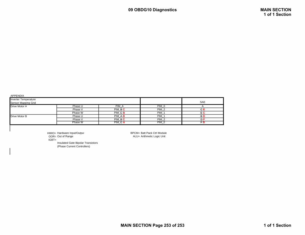
APPENDIXInverter Temperature Sensor Mapping Grid SAEDrive Motor A Phase U PIM_A PIM_0 A
Phase V PIM_B C PIM_2 C EPhase W PIM_C B PIM_1 E C
Drive Motor B Phase U PIM_A B PIM_1 B DPhase V PIM_B C PIM_2 D F Phase W PIM_C A PIM_0 F B
HWIO= Hardware Input/Output BPCM= Batt Pack Ctrl ModuleOOR= Out of Range ALU= Arithmetic Logic UnitIGBT=
Insulated Gate Bipolar Transistors (Phase Current Controllers)
09 OBDG10 Diagnostics MAIN SECTION1 of 1 Section
MAIN SECTION Page 253 of 253 1 of 1 Section