MAHARASHTRA STATE BOARD OF TECHNICAL...
28
MAHARASHTRA STATE BOARD OF TECHNICAL EDUCATION (Autonomous) (ISO/IEC - 27001 - 2005 Certified) WINTER– 15 EXAMINATION Subject Code: 17667 Model Answer Page 1 of 28 ________________________________________________________________________________________________________ Important Instructions to examiners: 1) The answers should be examined by key words and not as word-to-word as given in the Model answer scheme. 2) The model answer and the answer written by candidate may vary but the examiner may try To assess the understanding level of the candidate. 3) The language errors such as grammatical, spelling errors should not be given more Importance (Not applicable for subject English and Communication Skills. 4) While assessing figures, examiner may give credit for principal components indicated in the Figure. The figures drawn by candidate and model answer may vary. The examiner may give credit for any Equivalent figure drawn. 5) Credits may be given step wise for numerical problems. In some cases, the assumed constant Values may vary and there may be some difference in the candidate’s answers and model answer. 6) In case of some questions credit may be given by judgment on part of examiner of relevant answer based on candidate’s understanding. 7) For programming language papers, credit may be given to any other program based on equivalent concept. ___________________________________________________________________________________________ Q1. a) Attempt any THREE of the following: 12M i. State four advantages of electric motor as prime mover. Ans: 01M each Advantages of electric motor as prime mover: (Any 4) Electric drive is more flexible. It is more economical. It is cleaner as there is no fuel, fumes. It occupies less space as compared to other forms of drives and is, therefore, very compact source of drive. Its operating characteristics can easily be modified. It can be remote controlled. It requires less maintenance. It is reliable source of drive. ii. List different factors considered for selection of electric drives Ans: 01M each
Transcript of MAHARASHTRA STATE BOARD OF TECHNICAL...

MAHARASHTRA STATE BOARD OF TECHNICAL EDUCATION (Autonomous)
(ISO/IEC - 27001 - 2005 Certified)
WINTER– 15 EXAMINATION
Subject Code: 17667 Model Answer Page 1 of 28
________________________________________________________________________________________________________
Important Instructions to examiners:
1) The answers should be examined by key words and not as word-to-word as given in the
Model answer scheme.
2) The model answer and the answer written by candidate may vary but the examiner may try
To assess the understanding level of the candidate.
3) The language errors such as grammatical, spelling errors should not be given more
Importance (Not applicable for subject English and Communication Skills.
4) While assessing figures, examiner may give credit for principal components indicated in the
Figure. The figures drawn by candidate and model answer may vary. The examiner may give credit for any
Equivalent figure drawn.
5) Credits may be given step wise for numerical problems. In some cases, the assumed constant
Values may vary and there may be some difference in the candidate’s answers and model answer.
6) In case of some questions credit may be given by judgment on part of examiner of relevant answer based on
candidate’s understanding.
7) For programming language papers, credit may be given to any other program based on equivalent concept.
___________________________________________________________________________________________
Q1.
a) Attempt any THREE of the following: 12M
i. State four advantages of electric motor as prime mover.
Ans: 01M each
Advantages of electric motor as prime mover: (Any 4)
Electric drive is more flexible.
It is more economical.
It is cleaner as there is no fuel, fumes.
It occupies less space as compared to other forms of drives and is, therefore, very compact source of
drive.
Its operating characteristics can easily be modified.
It can be remote controlled.
It requires less maintenance.
It is reliable source of drive.
ii. List different factors considered for selection of electric drives
Ans: 01M each

MAHARASHTRA STATE BOARD OF TECHNICAL EDUCATION (Autonomous)
(ISO/IEC - 27001 - 2005 Certified)
WINTER– 15 EXAMINATION
Subject Code: 17667 Model Answer Page 2 of 28
________________________________________________________________________________________________________
Factors:- (Any 4)
1 Nature of electric supply:
Whether A.C. or pure D.C. Or rectified A.C supply is to be utilized for motor.
2. Nature of the drive:
Whether motor is to be drive individual machines or a group of machines.
3. Nature of load:
Whether the load requires light or heavy starting torque. Whether load torque increases
with speed or remains constant. Whether load has heavy inertia which may require long starting time.
4. Electrical characteristics of motors:
i. Starting characteristic.
ii. Running characteristic
iii. Speed control.
iv. Braking characteristics.
5. Size and rating of motor:
i. Whether motor is to run continuously, intermittently, or on a variable load cycle.
ii. Whether over load capacity and pull out torque are sufficient.
6. Mechanical considerations:
i. Type of enclosures.
ii. Type of bearings.
iii. Transmission of drive.
iv. Noise level.
7. Cost:
i. Capital cost.
ii. Running cost.
iii. Draw block diagram of microcomputer based speed control of synchronous motor.
Ans:
Diagram:- 4M

MAHARASHTRA STATE BOARD OF TECHNICAL EDUCATION (Autonomous)
(ISO/IEC - 27001 - 2005 Certified)
WINTER– 15 EXAMINATION
Subject Code: 17667 Model Answer Page 3 of 28
________________________________________________________________________________________________________
iv) Draw the circuit diagram of single phase full controlled bridge converter along with waveforms
Ans:
Diagram:- 02M
Wave form 02M

MAHARASHTRA STATE BOARD OF TECHNICAL EDUCATION (Autonomous)
(ISO/IEC - 27001 - 2005 Certified)
WINTER– 15 EXAMINATION
Subject Code: 17667 Model Answer Page 4 of 28
________________________________________________________________________________________________________
b) Attempt any ONE of the following: 6M
i) Describe four quadrant operation of a drive with the help of speed-torque characteristics.
Ans:
Diagram: 03M
Explanation: 03M
First quadrant operation-Forward motoring: Power is positive ie power flow is from source to load Motor
rotates in clock wise direction. P
Second quadrant operation-Forward Braking: Power is negative ie power flow is from load to source. Motor
rotates in anti-clock wise direction.
Third quadrant operation-Reverse motoring:. Power is positive ie. power flow is from source to load. Motor
rotates in clock wise direction.
Fourth quadrant operation- Reverse braking. Power is negative ie power flow is from load to source. Motor
rotates in anti- clock wise direction.

MAHARASHTRA STATE BOARD OF TECHNICAL EDUCATION (Autonomous)
(ISO/IEC - 27001 - 2005 Certified)
WINTER– 15 EXAMINATION
Subject Code: 17667 Model Answer Page 5 of 28
________________________________________________________________________________________________________
ii) With the help of neat diagram explain the operation of three phase semi-converter.
Ans:
Diagram 03M
Explanation: 03M
Three phase semi converter drive consist of 3 SCR’s and 3 diodes. Load is inductive. Three phase semi
converters are used in industrial applications up to 120 KW where a single quadrant operation is required. The
power factor of 3 phase semi converter drive is better than 3 phase half wave converter drive.
If S1 is fired at 30 º + α, S1 and D3 conduct, line voltage Vac appears across the load. For the
voltage Vba, S2 and D1 conduct and for the voltage Vcb, S3 and D2 conduct.
For firing angle > 90 º, waveform is discontinuous.
Average dc output voltage is 3√3Vm(1+ Cos α)/ (2π)
Q2. Attempt any FOUR of the following: 16M
a) State four breaking methods of an electric drive
Ans:-
Four braking methods of an electric drive (Any four ) 01M each
Plugging/Counter current braking
Dynamic braking
Regenerative braking
Mechanical braking

MAHARASHTRA STATE BOARD OF TECHNICAL EDUCATION (Autonomous)
(ISO/IEC - 27001 - 2005 Certified)
WINTER– 15 EXAMINATION
Subject Code: 17667 Model Answer Page 6 of 28
________________________________________________________________________________________________________
b) List different requirement of motors used for machine-tool applications
Ans:-
The requirements of motors used for machine tools are: (Any four requirements) 01M each
The motor must be reliable & low cost, requiring less maintenance.
They must be capable of speed control.
The acceleration & the motor should be sufficiently fast to avoid motor heating during starting.
Some machine tools require very high speed of operation.
Numerically controlled machine tools are being preferred to conventional machine tools.
The requirements of the drive motor are fast response, wide range of speed control, low
vibrations, better thermal capacity, low maintenance etc.
Due to the simple, economical & robust construction, reliability & less maintenance, squirrel
cage and converter fed induction motors are suitable for driving machine tools.
c) Describe working of two quadrant chopper drive with the help of circuit diagram and waveform
Ans:-
Type C chopper drive
Explanation: 02M
Type C chopper is a two quadrant chopper drive. It is suitable for forward motoring and forward
braking. The first quadrant is forward motoring and second quadrant is forward braking. It operates in First and
second quadrant.
Circuit diagram: 01M

MAHARASHTRA STATE BOARD OF TECHNICAL EDUCATION (Autonomous)
(ISO/IEC - 27001 - 2005 Certified)
WINTER– 15 EXAMINATION
Subject Code: 17667 Model Answer Page 7 of 28
________________________________________________________________________________________________________
Waveforms: 01M
OR
Type D chopper drive
Explanation: 02M
Type D chopper is a two quadrant chopper drive. It is suitable for forward motoring and regenerative
braking. The first quadrant is forward motoring and second quadrant is forward braking. It operates in First and
fourth quadrant.
Circuit diagram: 01M
Waveforms: 01M

MAHARASHTRA STATE BOARD OF TECHNICAL EDUCATION (Autonomous)
(ISO/IEC - 27001 - 2005 Certified)
WINTER– 15 EXAMINATION
Subject Code: 17667 Model Answer Page 8 of 28
________________________________________________________________________________________________________
d) List any four advantage of converter fed induction motor.
Ans:-
01M each
Advantages of converter fed induction motor:- (Any 4 )
1. Smooth acceleration at constant current and torque can be obtained.
2. Smooth start-up can be achieved.
3. High moment of inertia can be accelerated.
4. Switching surges can be avoided.
5. Speed control method is easy.
e) Draw labeled block diagram of PWM controlled method of induction motor. List any two advantages
Ans:-
Diagram – 03 M
Advantages: (Any two ) ½ each
Torque pulsations are avoided.
Losses are reduced.
Lower order harmonics are completely eliminated.
Input power factor is high.
Filters need not be used.

MAHARASHTRA STATE BOARD OF TECHNICAL EDUCATION (Autonomous)
(ISO/IEC - 27001 - 2005 Certified)
WINTER– 15 EXAMINATION
Subject Code: 17667 Model Answer Page 9 of 28
________________________________________________________________________________________________________
f) What is the need of multi-phase chopper? Explain its working with circuit diagram.
Ans:
Need of multi-phase chopper: 01M
The generated harmonics in the supply can be reduced.
The size of the filter is reduced.
The load current requirement can be increased.
Working: 01M
It is a two chopper configuration. Chopper 1 and chopper 2 Class A choppers connected in
load. There are two operating modes:
In phase mode: In this mode both the choppers are turned ON and turned OFF simultaneously.
Phase shift mode: In this mode both the choppers are turned ON at different instants of time.
Circuit diagram: 01M
Waveforms: 01M
i) In-phase mode:
ii) Phase- shift mode:

MAHARASHTRA STATE BOARD OF TECHNICAL EDUCATION (Autonomous)
(ISO/IEC - 27001 - 2005 Certified)
WINTER– 15 EXAMINATION
Subject Code: 17667 Model Answer Page 10 of 28
________________________________________________________________________________________________________
Q3 Attempt any FOUR of the following: 16M
a) Identify suitable type of chopper drive for reversible regenerative braking of DC drive. Justify with neat
sketches.
Ans:
Diagram 02M

MAHARASHTRA STATE BOARD OF TECHNICAL EDUCATION (Autonomous)
(ISO/IEC - 27001 - 2005 Certified)
WINTER– 15 EXAMINATION
Subject Code: 17667 Model Answer Page 11 of 28
________________________________________________________________________________________________________
Fig. quadrant diagram for four quadrant chopper drive
Explanation: 02M
Type E-chopper :-
It is more suitable for reversible regenerative braking of DC drive because,
We can control drive in all 4 quadrant & smoothly we can enter in to reversible regenerative braking mode
of drive.
Direction of rotation of the motor is possible.
Regenerative braking in either direction is possible.
Fast dynamic response.
Closed loop control of motor is possible.
b) With the help of circuit diagram and waveform, explain the working of dc chopper using power MOSFET.
Ans:
Diagram: 01M

MAHARASHTRA STATE BOARD OF TECHNICAL EDUCATION (Autonomous)
(ISO/IEC - 27001 - 2005 Certified)
WINTER– 15 EXAMINATION
Subject Code: 17667 Model Answer Page 12 of 28
________________________________________________________________________________________________________
Fig. circuit diagram of DC chopper using power MOSFET
Waveform 01M
Fig. Voltage and current waveforms.
Explanation: 02M
The semi-conductor device used is power MOSFET. Load is inductive and free-wheeling diode is used.
The gate control circuit provides rectangular voltage waveform.
The duty cycle of the chopper can be controlled by varying this waveform. When the gate voltage is high,
MOSFET is ON and acts like closed Switch.
Load voltage is positive and load current rises exponentially and inductor stores energy. When the gate
Voltage is zero, MOSFET is OFF and acts like open switch.
Load voltage is zero and load current decays exponentially and stored energy in the inductor is dissipated.
c) Draw power circuit for 3 phase dual converter with neat labeled diagram . Give its application.
Ans:
Daigram: 02M

MAHARASHTRA STATE BOARD OF TECHNICAL EDUCATION (Autonomous)
(ISO/IEC - 27001 - 2005 Certified)
WINTER– 15 EXAMINATION
Subject Code: 17667 Model Answer Page 13 of 28
________________________________________________________________________________________________________
Power circuit for 3 phase dual converter
Application(Any two) 02M
Note: give marks for relevant applications
Industrial Equipment’s.
Speed control of DC motor.
Used in high power applications.
d) Compare Dc shunt and dc series motor with reference to its construction , characteristics and application.
Ans: (Construction 1 ½ M, Characteristics 1 ½ M , Application.1M)
Parameters DC Shunt Motor DC Series Motor
Construction
In DC shunt Motor filed winding is connected
in parallel with the armature of the motor.
In DC series Motor filed winding is
connected in series with the armature of the
motor.

MAHARASHTRA STATE BOARD OF TECHNICAL EDUCATION (Autonomous)
(ISO/IEC - 27001 - 2005 Certified)
WINTER– 15 EXAMINATION
Subject Code: 17667 Model Answer Page 14 of 28
________________________________________________________________________________________________________
Characteristics
T α Ia
Ø α Ia
Application Due to constant speed motor it is used for belt
drive application, industrial and automotive
applications.
Used in small electrical application, mobile
electric equipment’s and used in hoist.
e) Compare AC drives and DC drives based on:
i) Working
ii) Type of motor
iii) Power circuit used
iv) Applications
Ans: 1M each
Parameter AC Drive DC Drive
1. Working
AC drive works on frequency.
DC drive works on voltage.
2. Type of motor
AC Motor. DC Motor.
3. Power circuit used
Cyclo converter or inverter AC to DC Converter or chopper.
4. Applications Used in machine tool & traction
application.
Used in traction, paper mill,
Textile mill.

MAHARASHTRA STATE BOARD OF TECHNICAL EDUCATION (Autonomous)
(ISO/IEC - 27001 - 2005 Certified)
WINTER– 15 EXAMINATION
Subject Code: 17667 Model Answer Page 15 of 28
________________________________________________________________________________________________________
Q4
a) Attempt any THREE of the following: 12M
i) State importance of phase failure protection in 3phase drives.
Ans:-
Importance of phase failure protection in 3phase drives (Any 4) 1M each
The reasons for phase failure are:
Blown fuse in some part of power distribution system
Mechanical failure within the switching equipment
Three phase induction motors running on 1phase draw all the current from the remaining two lines.
Because of these reasons the motor will draw more current. This will cause heating of the motor and will
damage the motor.
Hence phase failure protection is required. Relays are used for protection.
ii) Describe the effect of increasing rotor resistance in an induction motor with the help of speed torque
Characteristics
Ans:-
Characteristics: 2M
Explanation: 2M
In a slip-ring induction motor, an external 3phase star connected rheostat is connected to the rotor
of the motor. The speed of the motor can be varied by varying the resistance. As the rotor resistance increases,
the speed decreases but the maximum torque remains the same.
iii) Describe the role of microprocessor for speed control of DC motor with neat block diagram.
Ans:-
Block diagram: 2M

MAHARASHTRA STATE BOARD OF TECHNICAL EDUCATION (Autonomous)
(ISO/IEC - 27001 - 2005 Certified)
WINTER– 15 EXAMINATION
Subject Code: 17667 Model Answer Page 16 of 28
________________________________________________________________________________________________________
Role of micro-processor for speed control of drives: (Any four) 2M
Generating and providing firing pulses to the convertors.
Generating of necessary waveforms to feed the motors.
Processing the measured signal, such as voltage , current and speed.
Storing and processing the information of controlled quantities.
Identification and adaptation of variable parameters.
Adaptive control and optimization
General sequencing control
Monitoring and warning
Diagnostics and tests
iv) List any four function performed by microprocessor in speed control of industrial drives
Ans:-
Functions of microprocessor in speed control of industrial drives:(any four points) 1M each
Generating and providing firing pulses to the convertors.
Generating of necessary waveforms to feed the motors.
Processing the measured signal, such as voltage , current and speed.
Storing and processing the information of controlled quantities.
Identification and adaptation of variable parameters.
Adaptive control and optimization

MAHARASHTRA STATE BOARD OF TECHNICAL EDUCATION (Autonomous)
(ISO/IEC - 27001 - 2005 Certified)
WINTER– 15 EXAMINATION
Subject Code: 17667 Model Answer Page 17 of 28
________________________________________________________________________________________________________
General sequencing control
Monitoring and warning
Diagnostics and tests
Q.4
b) Attempt any one of the following: 6M
i) Draw block diagram of basic elements of a drive. Explain each block in detail.
Ans:-
Diagram: 3M
Explanation: 3M
Energy source: it can be an AC source or a DC source. It depends on the type of power modulator
used.
Power Modulator: It modulates the power flow from source to the motor. It limits the source current
during starting and braking. Examples are rectifier, chopper inverter etc.
Motor: It converts electrical energy to mechanical energy. Types are servo motor, synchronous motor,
etc.
Sensing unit: It senses the load parameter like speed or position and produces a signal proportional to
the sensed parameter. The output goes to the control unit.
Control unit: It compares input command signal and feedback signal and produces a command signal
which drives the power modulator to reduce the error.
ii) Which type of drive/motor is used in steel- rolling mill at each stage? State specifications of drive at each
stage
Ans:-
MAHARASHTRA STATE BOARD OF TECHNICAL EDUCATION (Autonomous)
(ISO/IEC - 27001 - 2005 Certified)
WINTER– 15 EXAMINATION
Subject Code: 17667 Model Answer Page 18 of 28
________________________________________________________________________________________________________
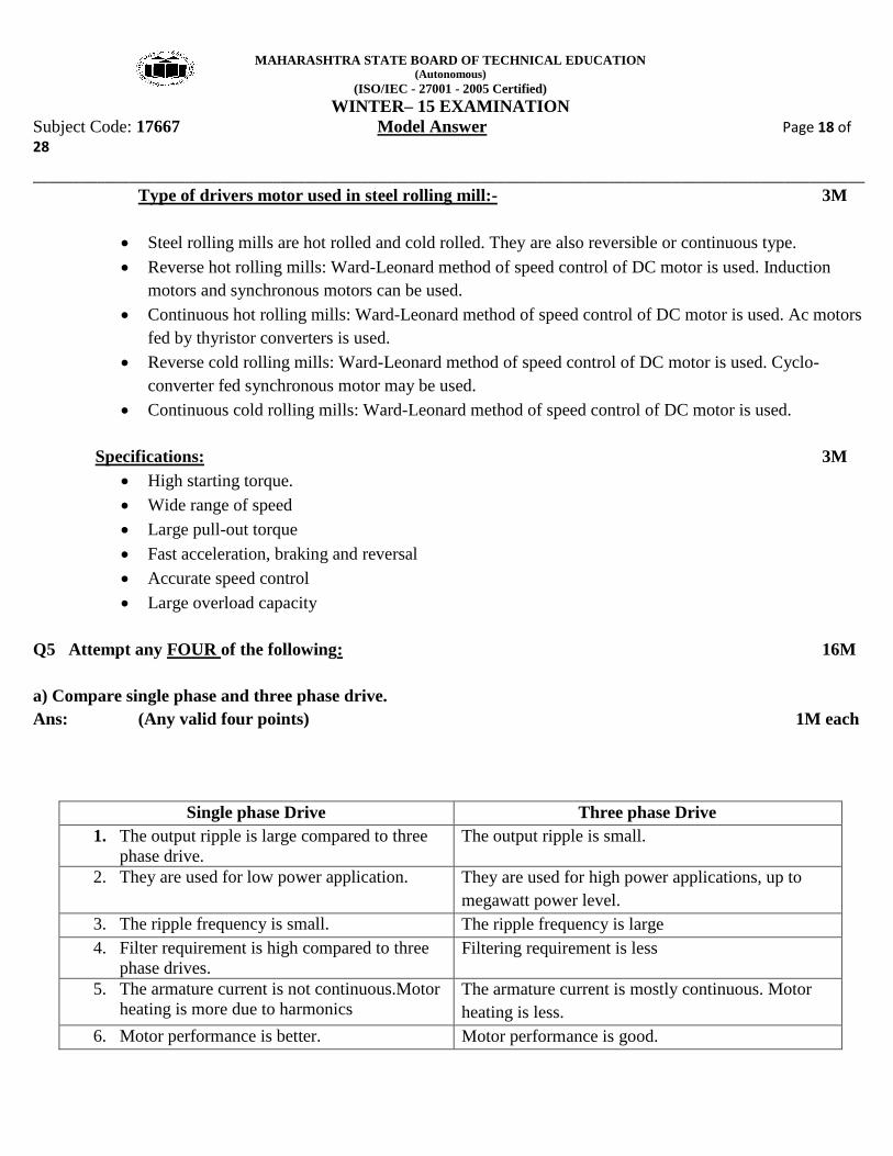
Type of drivers motor used in steel rolling mill:- 3M
Steel rolling mills are hot rolled and cold rolled. They are also reversible or continuous type.
Reverse hot rolling mills: Ward-Leonard method of speed control of DC motor is used. Induction
motors and synchronous motors can be used.
Continuous hot rolling mills: Ward-Leonard method of speed control of DC motor is used. Ac motors
fed by thyristor converters is used.
Reverse cold rolling mills: Ward-Leonard method of speed control of DC motor is used. Cyclo-
converter fed synchronous motor may be used.
Continuous cold rolling mills: Ward-Leonard method of speed control of DC motor is used.
Specifications: 3M
High starting torque.
Wide range of speed
Large pull-out torque
Fast acceleration, braking and reversal
Accurate speed control
Large overload capacity
Q5 Attempt any FOUR of the following: 16M
a) Compare single phase and three phase drive.
Ans: (Any valid four points) 1M each
Single phase Drive Three phase Drive
1. The output ripple is large compared to three
phase drive.
The output ripple is small.
2. They are used for low power application. They are used for high power applications, up to
megawatt power level.
3. The ripple frequency is small. The ripple frequency is large
4. Filter requirement is high compared to three
phase drives.
Filtering requirement is less
5. The armature current is not continuous.Motor
heating is more due to harmonics
The armature current is mostly continuous. Motor
heating is less.
6. Motor performance is better. Motor performance is good.

MAHARASHTRA STATE BOARD OF TECHNICAL EDUCATION (Autonomous)
(ISO/IEC - 27001 - 2005 Certified)
WINTER– 15 EXAMINATION
Subject Code: 17667 Model Answer Page 19 of 28
________________________________________________________________________________________________________
b) A four pole three phase induction motor operates from a 240V supply at 50Hz. Calculate:
(i) Speed of rotating magnetic flux.
(ii) Speed of rotor if slip id 0.04.
(iii) Speed of rotor if slip is 0.03.
(iv) Frequency of rotor at standstill.
Ans:-
Given data,
Motor = 4 pole, 3 phase Induction motor
Supply voltage =240 voltage
Frequency=50Hz
i) Speed of rotating magnetic flux(NS) 01M
NS =
=
NS = 1500rpm
ii) Speed of rotor(N) 01M
N = NS(1-S)
Where S = 0.04
N = 1500(1-0.04)
N = 1440rpm
iii) Speed of rotor(N) 01M
N = NS(1-S)
Where S = 0.03
N = 1500(1-0.03)
= 1455rpm
iv) Frequency of rotor at standstill (fr) 01M
fr = S*f
Where S=1
fr = 1*50
fr = 50 Hz

MAHARASHTRA STATE BOARD OF TECHNICAL EDUCATION (Autonomous)
(ISO/IEC - 27001 - 2005 Certified)
WINTER– 15 EXAMINATION
Subject Code: 17667 Model Answer Page 20 of 28
________________________________________________________________________________________________________
c) Describe the working of voltage/frequency control using square-wave inverter.
Ans:-
Diagram 02M
Explanation: 02M
The output voltage of square wave inverter a variable DC voltage is required on the input side of the
inverter. This is obtained from a 3 phase converter, filter combination on the input side of the inverter. The
output frequency of the Inverter can be changed by changing the rate at which the devices connected in the
inverter are switched ON & OFF. The VCO frequency will vary in proportional with DC controlled voltage
to vary the inverter output frequency.
The output waveform of the Inverter is a 6 step square waveform. A low percentage of harmonics will
reduce the meter heating. Both the output frequency & voltage of the inverter should be variable in order to
vary them simultaneously to keep the ratio constant . a common voltage control (Vc) is used to vary both
F1 and to vary both F1 and α. The firing angle of three phase converter is changed in proportional with output
voltage of the flux control circuit.
The control voltage (Vc) is obtained from a ramp function generator .
The Ramp Frequency generator provides the start required at the starting of Induction motor.
Disadvantages of Square wave inverter:
NOTE: DISADVANTAGES NOT COMPULSORY
The output voltage waveform contains lower order harmonics, which effects the motor heating specially.
The input power factor of the converters is dependent on the firing angle α which is very poor at high value
of α i.e. at low motor speed.

MAHARASHTRA STATE BOARD OF TECHNICAL EDUCATION (Autonomous)
(ISO/IEC - 27001 - 2005 Certified)
WINTER– 15 EXAMINATION
Subject Code: 17667 Model Answer Page 21 of 28
________________________________________________________________________________________________________
d) List different requirements of motor used for paper-mill application.
Ans:-
The paper mill machine should satisfy the following requirements. (Any four) 01 M each
The speed of the paper machine must be constant in video of economy while forming the sheets of paper.
A speed control range of 10:1 is required so that it is suitable for performing several jobs.
The arrangement should be capable of taking up sag.
Even with correct speeds in the last 2 sections, uneven drying or the paper may cause variations in tension,
which must be taken care of by suitable tension control.
The motor must be capable of including in order that the wire be cleaned up.
Every section must be able to run at crawling speeds.
The starting and acceleration of the sections must be smooth as well as quick.
e) Draw the circuit diagram and waveforms for single phase semi-converter with symmetrical and
asymmetrical configuration.
Ans:-
Diagram 02M
Waveform 02M
MAHARASHTRA STATE BOARD OF TECHNICAL EDUCATION (Autonomous)
(ISO/IEC - 27001 - 2005 Certified)
WINTER– 15 EXAMINATION
Subject Code: 17667 Model Answer Page 22 of 28
________________________________________________________________________________________________________
Fig. circuit diagram & waveforms
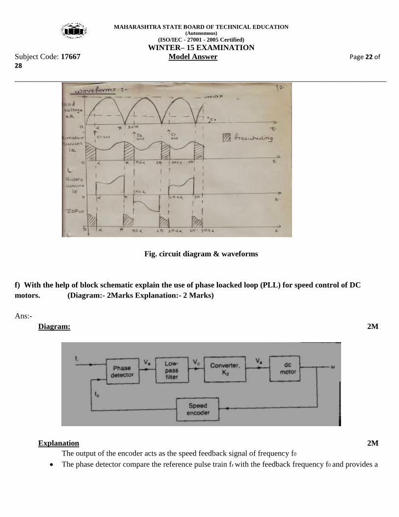
f) With the help of block schematic explain the use of phase loacked loop (PLL) for speed control of DC
motors. (Diagram:- 2Marks Explanation:- 2 Marks)
Ans:-
Diagram: 2M
Explanation 2M
The output of the encoder acts as the speed feedback signal of frequency f0
The phase detector compare the reference pulse train fr with the feedback frequency f0 and provides a

MAHARASHTRA STATE BOARD OF TECHNICAL EDUCATION (Autonomous)
(ISO/IEC - 27001 - 2005 Certified)
WINTER– 15 EXAMINATION
Subject Code: 17667 Model Answer Page 23 of 28
________________________________________________________________________________________________________
pulse width modulated output voltage Ve which is proportional to the difference in phases and
references and feedback pulse trains.
The phase detector is available in integrated circuits.
A low pass loop filter converts the pulse train Ve to a continuous dc level Vc which varies the output of
the power convertor and in turn the motor speed.
The response of the phase detector is very fast.
Q6. Attempt any four of the following: 16M
a) List four ratings and four specifications of stepper motor.
Ans:
Ratings of stepper motor are:- (ANY FOUR) 04M
Step angle –full step or half step-1.8 deg/0,9deg
Micro stepping -bipolar unipolar
Holding torque- 2000gm-cm
NEMA frame size size 17
Shaft diameter- 0.197 inches
Power – 5 watts
Voltage and current – 12V and 400mA
Phase windings-4/2
Ambient temperature-10 -55 deg centigrade
Insulation resistance-greater than 100Mega Ohm at 500V D.C
b) Which type of drive motor is suitable for robotic arm? Explain its working with the diagram.
Ans:
NOTE: ANY OTHER RELEVANT BLOCK DIAGRAM USING STEPPER MOTOR CAN
BE CONSIDERED
Diagram 02M

MAHARASHTRA STATE BOARD OF TECHNICAL EDUCATION (Autonomous)
(ISO/IEC - 27001 - 2005 Certified)
WINTER– 15 EXAMINATION
Subject Code: 17667 Model Answer Page 24 of 28
________________________________________________________________________________________________________
Explanation:- 02M
DC servo motor is suitable for Robotic Arm.
1. Servo motor is nothing but a simple electrical motor with the help of servomechanism.
2. There are some applications of motor where rotation of the motor is required for just a certain angle not
continuously for long period of time.
3. A servo motor is mainly consist of a DC motor, gear system, a position sensor (potentiometer) and control
element.
4. Motor is connected to gear box assembly to provide feedback to position sender.
5. Output of motor is given to servomotor arm through servo spline.
6. Potentiometer changes position according to current position of motor.
7. So change in resistance provide change in voltage.
8. And then it is compared with voltage from feedback potentiometer.
9. Then error signal is amplified & given to motor and then much angle rotation of robotic arm/leg takes place.
10. Position or rotation of robotic arm /leg is depends on PWM control signal.
c) List the different speed control methods of induction motor. Explain any one in detail.
Ans:
Note: Any one method can be explained.

MAHARASHTRA STATE BOARD OF TECHNICAL EDUCATION (Autonomous)
(ISO/IEC - 27001 - 2005 Certified)
WINTER– 15 EXAMINATION
Subject Code: 17667 Model Answer Page 25 of 28
________________________________________________________________________________________________________
The Speed of Induction Motor is changed from Both Stator and Rotor Side 1M
The speed control of three phase induction motor from stator side are further classified as :
1. V / f control or frequency control.
2. Changing the number of stator poles.
3. Controlling supply voltage.
4. Adding rheostat in the stator circuit.
The speed controls of three phase induction motor from rotor side are further classified as:
1. Adding external resistance on rotor side.
2. Rotor voltage control
Rotor resistance control using chopper
Diagram:- 2M
Fig: chopper controlled induction motor
Explanation: 01M
i) Speed control by means of slip variation can be achieved by using a variable resistance in the rotor circuit. The
maximum value of torque does not depend upon the value of rotor resistance.
ii) Rotor resistance influences the slip at which maximum torque occurs. External resistances can be added very
conveniently to the phases of the slip ring induction motor.
iii) With the development of thyristors which has lead to the chopper control resistance in the rotor circuit.
iv) The resistance across output terminal of a chopper can be varied from 0 to R by changing the time ratio(Duty
cycle) of the chopper. The slip power of the rotor is rectified through a diode bridge rectifier and fed to the chopper
control resistance.
v) The smoothing induction is used in the circuit to maintain the current at constant value.

MAHARASHTRA STATE BOARD OF TECHNICAL EDUCATION (Autonomous)
(ISO/IEC - 27001 - 2005 Certified)
WINTER– 15 EXAMINATION
Subject Code: 17667 Model Answer Page 26 of 28
________________________________________________________________________________________________________
vi) The rating of the chopper decides the maximum rotor current of the motor.
vii) It is suitable for load such as elevators, lifts but the speed control range is limited by the resistance.
OR
Stator Voltage Control Method
Explanation :
Two SCRs are connected anti parallel.
During the positive half cycle SCR1 is triggered.
The direction of the current in the stator winding is from the top to bottom.
In the negative half cycle SCR1 is turned off and SCR2 is triggered.
The direction of the flow of current in the stator winding is reversed biased.
By varying the firing angles of SCR1 and 2, the magnitude of a.c. voltage across
the stator winding of the motor can be controlled.
This in turn will vary the motor speed.
OR
Slip energy recovery system method:-
Diode D1, D2, D3, D4, D5 and D6 acts as a rectifier.
L, C1 and C2 form a pie network filter.
SCRs 1, 2,3,4,5 and 6 act as an inverter.

MAHARASHTRA STATE BOARD OF TECHNICAL EDUCATION (Autonomous)
(ISO/IEC - 27001 - 2005 Certified)
WINTER– 15 EXAMINATION
Subject Code: 17667 Model Answer Page 27 of 28
________________________________________________________________________________________________________
The firing angle of the inverter can vary the amount of power extracted from rotor
circuit and thus the rotor speed is varied.
The power output of inverter circuit is fed back to the a.c. supply mains and t his
forms a regenerative control.
The system is made closed loop by comparing actual speed and torque and the
desired speed and torque of motor with the help of tacho-generator
OR
Chopper control of induction motor drive employing motor resistance control technique
Diode D1,D2,D3,D4,D5 and D6 acts as a rectifier.
L,C1 and C2 form a pie network filter.
The chopper is controlled at high frequency and thus connecting and disconnecting the
external Resistance are in the rotor circuit at regular intervals.
Hence the Motor speed can be controlled.
The system is made closed loop by comparing actual speed and torque and the
desired speed and torque of motor with the help of tacho generator.
d) Write different stages and drives required for sugar mills.
Ans:
Different stages 02M

MAHARASHTRA STATE BOARD OF TECHNICAL EDUCATION (Autonomous)
(ISO/IEC - 27001 - 2005 Certified)
WINTER– 15 EXAMINATION
Subject Code: 17667 Model Answer Page 28 of 28
________________________________________________________________________________________________________
1.Separation: In sugar mill the sugar crystals are separated from the syrup by mean of a centrifuge. The
separation is accomplished by the centrifugal set up.
2. Charging:-The centrifuge is started to a speed of around 200rpm at which the charging of syrup takes place.
during charging the motor is disconnected from the supply.
3. Plugging:-the centrifuge is spun at speed of 500 & 1000 rpm. -the speed is then reduced in steps to about50
rpm, at which plugging takes place. -A typical load cycle of a centrifuge is Shown below
Drives used for sugar mills 02M
1. The motor used to drive the centrifuge is a variable speed motor like slip ring induction motor.
Regenerative braking is employed. Stator voltage control can be used.
2. A synchronous motor or converter fed induction motor can also be used for speed control purposes.
e) Draw block diagram of closed loop control of synchronous motor.
Ans:
Diagram :- 04M