Maguire WSB 12 Software Manual · Web viewUnlike any previous liquid color pump, the MS4 PeriStep...
31
MAGUIRE PRODUCTS INC. MS4 4-Roller Pump MS4 4-Roller Pump INSTRUCTION MANUAL
Transcript of Maguire WSB 12 Software Manual · Web viewUnlike any previous liquid color pump, the MS4 PeriStep...

MAGUIRE PRODUCTS INC.MS4 4-Roller Pump
MS4 4-Roller Pump
INSTRUCTION MANUAL
Copyright Maguire Products, Inc. 2015

M S 4 4 - R o l l e r P u m p M A G U I R E P R O D U C T S , I N C .
Maguire Products Inc.
Model MS4 PeriStep™ 4-Roller Pump
Table of Contents
Pump Features _________________________________________________________4Principle of Pump Operation______________________________________________4Principle of Controller Operation __________________________________________5Pump Tubing___________________________________________________________5Description of Controls __________________________________________________6Startup Procedure ______________________________________________________7Run Modes___________________________________________________________10 Tube Selection Guide __________________________________________________14Changing Colors ______________________________________________________18Disassembly and Cleaning ______________________________________________18Wiring Diagram _______________________________________________________20Output Specifications __________________________________________________21Warranty _____________________________________________________________22Technical Support and Contact Information _______________________________23
Rev: May 1, 20152

M S 4 4 - R o l l e r P u m p M A G U I R E P R O D U C T S , I N C .
Copyright 2014 Maguire Products Inc.
The information contained within this manual including any translations thereof, is the property of Maguire Products Inc. and may not be reproduced, or transmitted in any form or by any means without the express written consent of Maguire Products Inc.
To every person concerned with use and maintenance of the Maguire MS4 4-Roller Pump it is recommended to read thoroughly these operating instructions. Maguire Products Inc. accepts no responsibility or liability for damage or malfunction of the equipment arising from non-observance of these operating instructions.
To avoid errors and to ensure trouble-free operation, it is essential that these operating instructions are read and understood by all personnel who are to use the equipment.
Should you have problems or difficulties with the equipment, please contact Maguire Products Inc. or your local Maguire distributor.
These operating instructions only apply to the equipment described within this manual.
Manufacturer’s Contact Information
Maguire Products Inc.11 Crozerville RoadAston, PA. 19014
Phone: 610.459.4300Fax: 610.459.2700
Website: http://www.maguire.com
Email: [email protected]
Rev: May 1, 2015 3

M S 4 4 - R o l l e r P u m p M A G U I R E P R O D U C T S , I N C .
Maguire MS4 4-Roller Pump Features Positive Displacement Pump – No Seals or Check Valves Stepper Motor With No Gear Box for Precision Control Highly Efficient Planetary Roller Drive System Easy Load, Split-head Design Interlocked Drive Motor for Safety 3 Tubing Sizes for Wide Dosing Range 5 Year Warranty
Maximum Throughput capacity of liquid color:
By Volume:Up to 3.01 gal/hr (11.4 l/hr)
*By Weight: 32.2 lbs (14.6 kg) per Hour
*Result taken with liquid density of 10 lbs/gal (1.19 kg/l)
Principles of Pump Operation
The MAGUIRE PeriStep™ pumps are designed for years of rugged industrial service with little or no maintenance. Only the inexpensive pumping tube needs to be replaced from time to time to keep these units performing like new.
Metering is accomplished by the compression and release of a flexible pumping tube. These peristaltic pumps are true positive displacement pumps. Unlike other positive displacement pumps such as piston, gear, diaphragm, and rotary screw pumps, a peristaltic pump has no seals, check valves or clearances to allow even the slightest internal leakage. Liquid is retained within a flexible tube at all times and never comes into contact with any surfaces of the pumping mechanism. There are no check valves used at all.
Where tubing passes through the pump head, rollers alternately close off a portion of the tube and squeeze the liquid inside the tube forward by rolling over the tube in the forward direction. As the tube behind the roller springs back to its original round shape, the expanding inside cavity creates a vacuum that draws liquid into the tube. At least one roller is always in the position of closing off the tube completely, thereby assuring that no liquid can "leak" backwards.
Pumping is so complete that this type of pump can pump air as effectively as liquid and can develop a near full vacuum of 30 inches of mercury. These pumps are self-priming and will pass any entrapped air bubbles in the liquid through the pump without loss of prime.
A highly accurate stepper motor drives the pump’s rollers. As the rollers move over the tube, they cause the liquid inside to be squeezed forward in small uniform increments. The accuracy of these pumps for metering small amounts of viscous liquids is unmatched.
Rev: May 1, 20154

M S 4 4 - R o l l e r P u m p M A G U I R E P R O D U C T S , I N C .
Principle of Controller Operation
Depending of the your specific application, the MS4 signal cord can be attached to a contact closure signal for continuous and cycle application, or a variable 0-10 V DC signal for extrusion following applications.
Unlike any previous liquid color pump, the MS4 PeriStep™ liquid color pump has an input parameter for the liquid color density (lbs/gal or kg/l). Because of this, no weight calibration is required. Simply enter in the liquid color density that you are using, and the tubing factor associated with the tube set you are using. With the correct data entered, the MS4 will always provide accurate, consistent throughput.
When used in cycle mode, the speed of the stepper motor is automatically controlled by the internal microprocessor to allow color metering to occur uniformly over the entire screw return cycle. The operator need not concern himself with motor speed adjustment. Changing cycle times or fluctuations in plant voltage are automatically detected and compensated for and, therefore, will have no effect on metering accuracy.
Two innovations are key to the MS4 PeriStep™ liquid color pump. Instead of a standard motor, the drive system is a stepper motor whose shaft rotates in discrete, minute increments that make possible precision and repeatability of movement. This motor drives a central "sun" roller, whose motion transfers to the "planetary" rollers that provide the compression / relaxation cycle of a peristaltic pump. Maguire has reduced the number of planetary rollers to four from the conventional six. The sun roller drives the planetary rollers by means of friction contact, providing a 5 to 1 speed reduction without a gear box.
Pump Tubing The MS4 PeriStep™ liquid color pump utilizes the same 3 tube sets that our traditional
MPA series pumps utilize. The tube sets are: green, red, and clear. They vary in size according to their color. Larger tube will offer higher throughput capabilities, whereas smaller tubing will offer higher accuracy and resolution. A choice should be made according to the users specific application. Please see the “throughput capacity” section of the manual for more information on this.
Tube Sets Part numbers:at07 – Pump tube with Fittings, 1/8” Green
at08 – Pump tube with Fittings, 3/16” Red
at09 – Pump tube with Fittings, 1/4” Clear
Rev: May 1, 2015 5

M S 4 4 - R o l l e r P u m p M A G U I R E P R O D U C T S , I N C .
Description of Controls
1. ON/OFF SWITCHThe power switch is simply the internal connection between the pump’s power cord and the pumps power supply. This switch has an internal indicator light that will glow when it is switched on and 120/230 VAC is present.
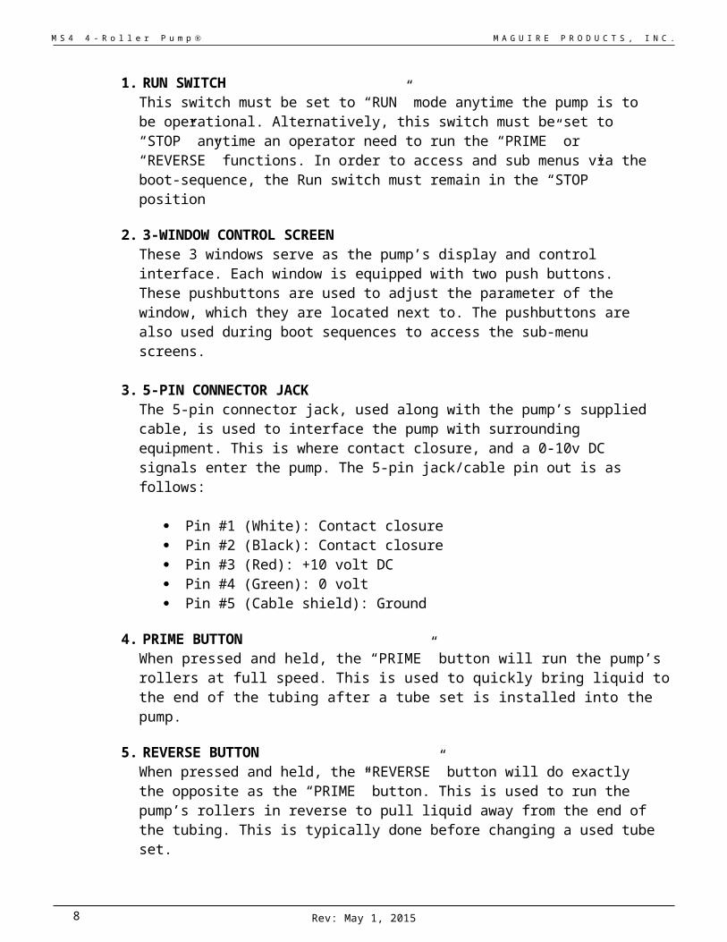
1. RUN SWITCHThis switch must be set to “RUN” mode anytime the pump is to be operational. Alternatively, this switch must be set to “STOP” anytime an operator need to run the “PRIME” or “REVERSE” functions. In order to access and sub menus via the boot-sequence, the Run switch must remain in the “STOP” position
2. 3-WINDOW CONTROL SCREENThese 3 windows serve as the pump’s display and control interface. Each window is equipped with two push buttons. These pushbuttons are used to adjust the parameter of the window, which they are located next to. The pushbuttons are also used during boot sequences to access the sub-menu screens.
3. 5-PIN CONNECTOR JACK The 5-pin connector jack, used along with the pump’s supplied cable, is used to interface the pump with surrounding equipment. This is where contact closure, and a 0-10v DC signals enter the pump. The 5-pin jack/cable pin out is as follows:
Pin #1 (White): Contact closure Pin #2 (Black): Contact closure Pin #3 (Red): +10 volt DC Pin #4 (Green): 0 volt Pin #5 (Cable shield): Ground
4. PRIME BUTTONWhen pressed and held, the “PRIME” button will run the pump’s rollers at full speed. This is used to quickly bring liquid to the end of the tubing after a tube set is installed into the pump.
5. REVERSE BUTTONWhen pressed and held, the “REVERSE” button will do exactly the opposite as the “PRIME” button. This is used to run the pump’s rollers in reverse to pull liquid away from the end of the tubing. This is typically done before changing a used tube set.
Rev: May 1, 20156

M S 4 4 - R o l l e r P u m p M A G U I R E P R O D U C T S , I N C .
MS4 4-Roller Pump Startup Procedure 1. Place color drum next to process machine.
2. Install pickup lance into liquid container for suction pickup of liquid, or attach tubing assembly in accordance with color manufacturer's recommendations.
3. There should be provision for attaching the poly-tubing to the process machine so as to allow color to be metered in directly over the feed section of the screw, or into a premixer if one is installed. Assuming provisions have been made, attach or install the poly-tubing to the process machine as required. (The best color mixing without color contamination of the feed throat of your machine is obtained when the color delivery tube is positioned approximately 1/2-inch over the screw at the forward edge of the feed throat toward the side of the screw that is turning downward.)
NOTE: Adaptor Plates are available from MAGUIRE PRODUCTS that mount between the hopper and feed throat. This will allow easy insertion and removal of the color delivery tube into the feed throat of the process machine.
4. Connect the power and signal cord as follows:
Plug the pump’s power cord into a standard 110 or 230 volt continuous power source. Plug the shielded 4-conductor "SIGNAL" cord into the 5-pin jack located on the same side of the pump. The white and black wires of this cable must be attached to a contact closure ONLY. This contact closure is used as a run signal to the pump in continuous and extrusion following mode, and a timing signal for cycle mode (see “wiring diagram” section of the manual). Additionally, the red (+) and green (-) wires should be connected to a 0-10 VDC extrusion speed signal if the pump is to be used in extrusion following mode. 5. Open the pump head by turning the hand screw counter-clockwise. Complete removal of the hand screw is not necessary. Lay the pump tube into the slot above the rollers in the pump head. The brass tube-inlet fitting should be against the right side of the pump head that faces forward.
The tube, properly installed, will be in contact with only the uppermost two rollers. The inlet end of the tube will be resting against the side of the pump head that faces forward. The tube will pass through the pump body in a nearly straight line and reappear out the other side of the pump head. Be sure that the tubing is pushed into the pump head far enough so that is not pinched by the outer portion of the pump head when it is to be closed. Close the pump head by turning the hand screw clockwise until the top portion of the pump head meets the bottom portion firmly. This should be lightly tightened. Over tightening the hand screw is unnecessary.
6. The pump can now be turned on via the power switch. At this point, the user should set the mode, let down ratio, fluid density, tubing factor, units of measurement, and throughput via the main menu and sub menus. Here are detailed instructions on how to perform all of these functions.
Rev: May 1, 2015 7
M S 4 4 - R o l l e r P u m p M A G U I R E P R O D U C T S , I N C .
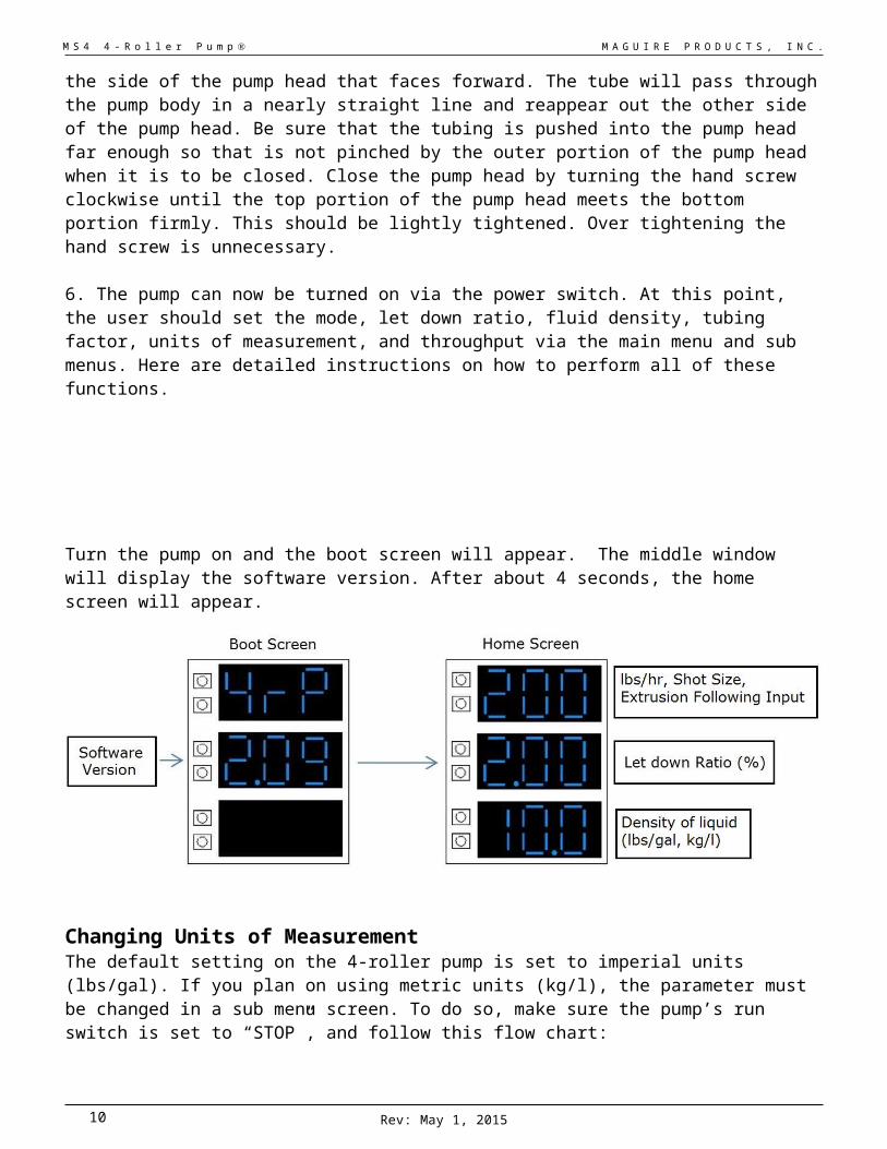
Turn the pump on and the boot screen will appear. The middle window will display the software version. After about 4 seconds, the home screen will appear.
Changing Units of MeasurementThe default setting on the 4-roller pump is set to imperial units (lbs/gal). If you plan on using metric units (kg/l), the parameter must be changed in a sub menu screen. To do so, make sure the pump’s run switch is set to “STOP”, and follow this flow chart:
To save these parameters and return to the home screen, toggle the run switch on then off before turning off power.
Rev: May 1, 20158

M S 4 4 - R o l l e r P u m p M A G U I R E P R O D U C T S , I N C .
Description of the Home Screen
In Continuous mode the top window will display the lbs/hr or kg/l. In Cycle mode it will display the shot size, and in Extrusion Following it will display the maximum extruder output.
For Continuous and Cycle modes, this parameter can be adjusted at the home screen using the two buttons next to the display.
For Extrusion Following mode, the top window is only an output display (in order to adjust XMO, a sub menu must be accessed).
In all modes the middle window will display the Let Down Ratio, or LDR. This can be adjusted from the home screen using the two buttons next to the display.
The bottom window will display the density in lbs/gal or kg/l of your liquid color. This parameter needs to be set by the user. It can be adjusted from the home screen using the two buttons next to the display.
Adjusting Display Brightness
You may want to adjust the display brightness to accommodate your specific working environments. To do this, make sure the pump’s run switch is set to “STOP”, and simply follow this flow chart:
To save these parameters and return to the home screen, toggle the run switch on then off before turning off power.
Rev: May 1, 2015 9
M S 4 4 - R o l l e r P u m p M A G U I R E P R O D U C T S , I N C .
Run modes for the MS4
The 4-Roller Pump is capable of running in three different modes: Continuous, Cycle, and Extrusion Following.
Continuous Mode
In Continuous mode, the MS4 will run the pump continuously at a rate set by the user.
The throughput of the pump can be calculated by:
PHR (lbs per hour) X LDR (let down ratio)
Example:
● PHR is set to 100 lbs/hr
● LDR set to 2%
The MS4 will pump: (100 lbs/hr)*(2% LDR) = 2 lbs/hr of color.
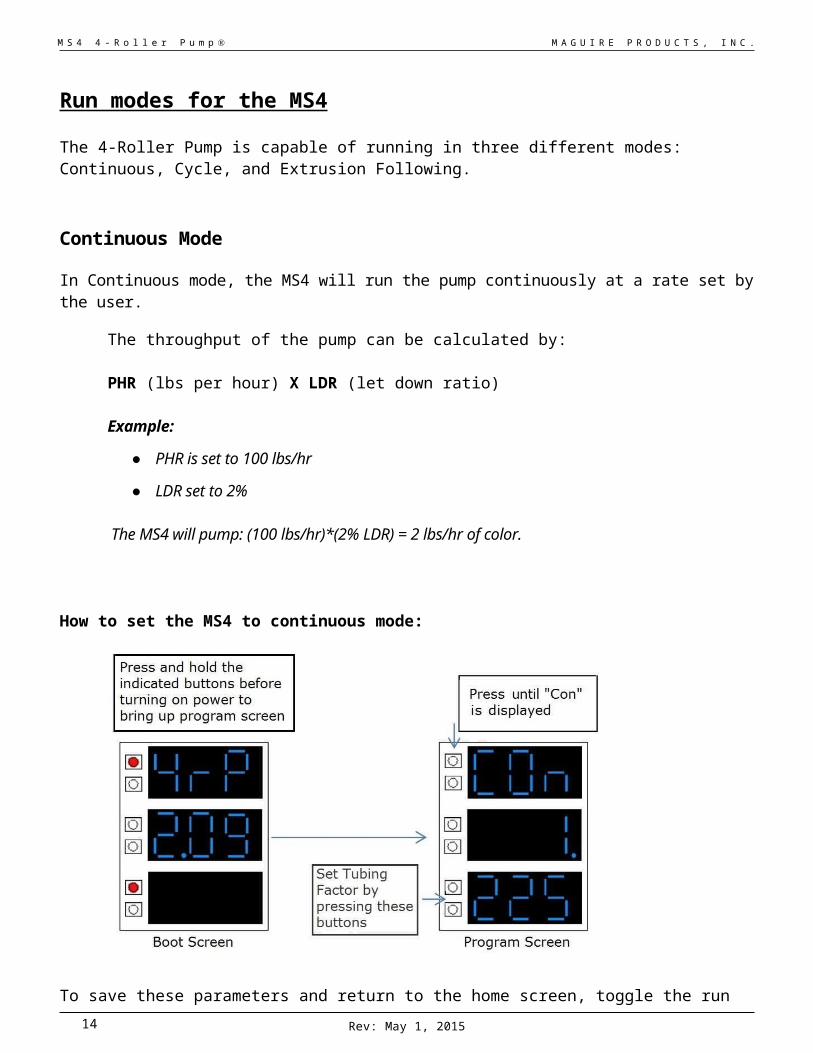
How to set the MS4 to continuous mode:
To save these parameters and return to the home screen, toggle the run switch on then off before turning off power.
Rev: May 1, 201510

M S 4 4 - R o l l e r P u m p M A G U I R E P R O D U C T S , I N C .
Injection Molding (Cycle Mode)
In Cycle mode, the MS4 will observe the time duration of contact closure between pin 1 and 2 (white and black leads of connected cable), and automatically adjust the pump rate in order to meet the shot size within that time interval of the screw return time.
Example: ● Shot size set to 100 grams ● LDR set to 2%● Contact closure time is 30 seconds.
The MS4 will pump: (100 grams)*(2% LDR) = 2.0 grams of color during that 30-second time interval.
How to set the MS4 to Cycle mode:
To save these parameters and return to the home screen, toggle the run switch on then off before turning off power.
Rev: May 1, 2015 11

M S 4 4 - R o l l e r P u m p M A G U I R E P R O D U C T S , I N C .
Extrusion Following Mode
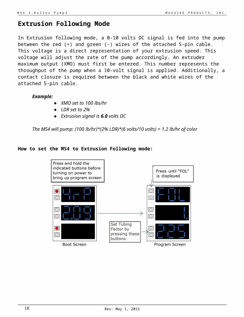
In Extrusion following mode, a 0-10 volts DC signal is fed into the pump between the red (+) and green (-) wires of the attached 5-pin cable. This voltage is a direct representation of your extrusion speed. This voltage will adjust the rate of the pump accordingly. An extruder maximum output (XMO) must first be entered. This number represents the throughput of the pump when a 10-volt signal is applied. Additionally, a contact closure is required between the black and white wires of the attached 5-pin cable.
Example:● XMO set to 100 lbs/hr● LDR set to 2%● Extrusion signal is 6.0 volts DC
The MS4 will pump: (100 lb/hr)*(2% LDR)*(6 volts/10 volts) = 1.2 lb/hr of color
How to set the MS4 to Extrusion Following mode:
Rev: May 1, 201512

M S 4 4 - R o l l e r P u m p M A G U I R E P R O D U C T S , I N C .
Setting XMO Value
XMO must be entered within a sub menu screen, not the home screen. To do so, make sure the pump’s run switch is set to “STOP”, and follow this flow chart:
To save these parameters and return to the home screen, toggle the run switch on then off before turning off power.
X-FactorRev: May 1, 2015 13
M S 4 4 - R o l l e r P u m p M A G U I R E P R O D U C T S , I N C .
Three different “X-factors” can be set within the parameters of the pump. Adjusting the X-factor changes the placement of the decimal point in the top window of the home screen. This will allow the user to enter a large range of throughput settings. The factory default is set to “1.”.
The 3 settings are as follows:
“0.1” This allows the user to enter in a value within this format: XX.XFor example, in continuous mode this setting would cover values from 0 to 99.9 lbs/hr with increments of .1 lb/hr
“1.” This allows the user to enter in a value within this format: XXX. For example, in continuous mode this setting would cover values from 0 to 999 lbs/hr with increments of 1 lb/hr
“10” This allows the user to enter in a value within this format: XXX*10For example, in continuous mode this setting would cover values from 0 to 9990 lbs/hr with increments of 10 lb/hr. If a user had “300” entered into the lbs/hr, the pump would actually be operating at: 300*10 = 3000 lbs/hr.
To set the X-factor, follow this flow chart:
To save these parameters and return to the home screen, toggle the run switch on then off before turning off power.
Tube Selection Guide Rev: May 1, 201514

M S 4 4 - R o l l e r P u m p M A G U I R E P R O D U C T S , I N C .
Tubing Factor
The MS4 can be supplied with 3 different diameter peristaltic tubes. Tubing size should be chosen according to the desired throughput. A larger I.D. tube will produce a greater throughput than a smaller I.D. tube given a fixed pump speed. Alternatively, a smaller tube will offer higher accuracy.
In order for the pump to produce accurate throughput, a tubing factor must be entered in order to compensate for the difference in tube size. The tubing factor can be set and adjusted by following the simple menu direction below.
If your throughput is greater than calculated, increase the tubing factor. If throughput is less than it should be, decrease the tubing factor. We have found the following tubing factors an accurate place to start:
Tube Tubing Factor1/8" I.D. (Green): 2103/16" I.D. (Red): 4651/4" I.D. (Clear): 735
Throughput of tubing will begin to diminish after prolonged use, due to tube deformation. This can be compensated by slightly adjusting the tubing factor over time, or simply replacing the tube set
altogether. This is typical of any peristaltic pump.
How to set tubing factor within MS4:
To save these parameters and return to the home screen, toggle the run switch on then off before turning off power.
Rev: May 1, 2015 15

M S 4 4 - R o l l e r P u m p M A G U I R E P R O D U C T S , I N C .
Choosing the Correct Tube Size
The MS4 has the capability of running its rollers up to 60 RPM with extreme accuracy. With an example fluid of 10 lbs/gal, the maximum throughput for each tube is as follows:
Maximum Throughput @ 10 lbs/gal (1.19 kg/l):
Tube lbs/hr Kg/hr1/8" I.D. (Green): 9.51 4.313/16" I.D. (Red): 20.4 9.251/4" I.D. (Clear): 32.2 14.6
Depending on the throughput of your specific application, use this guide to choose a tube size for optimal performance and accuracy. Just remember to enter in the corresponding tubing factor after you have made a choice.
Rev: May 1, 201516

M S 4 4 - R o l l e r P u m p M A G U I R E P R O D U C T S , I N C .
Enabling & Disabling Auto Stop
In order to run in Continuous or Extrusion Following modes, the MS4 will require a contact closure between the black and white wires of the attached 5-pin cable. In the rare event where a contact closure is unavailable, the need for one can be bypassed. Disabling the “auto stop” feature does this.
To enable or disable auto-stop, make sure the pump’s run switch is set to “STOP”, and follow this flow chart:
To save these parameters and return to the home screen, toggle the run switch on then off before turning off power.
Rev: May 1, 2015 17
M S 4 4 - R o l l e r P u m p M A G U I R E P R O D U C T S , I N C .
Changing Colors
1. Run the pump in REVERSE to empty the tube of color.
2. Remove pump tube from pump head.
3. Remove poly-tubing from process machine and coil entire tube onto top of drum. Do not disconnect any other fittings. Tape up the open end of the poly-tubing to prevent dripping of color.
4. Bring in next color drum and repeat Steps 5 & 6 of "Start Up Procedure".
Pickup Assembly
An inexpensive pickup assembly is fitted to the drum of color to be used. If one pump is going to run more than one color, each color drum should be equipped with its own pickup assembly.
Each pickup assembly consists of several components. All are connected together and should never be disassembled except in the case of a tube blockage caused by contaminants in the liquid color. The lance and threaded adaptor are installed directly into the lid of the drum. The other end of the tubing assembly is connected to the feed throat of the process machine.A common source of problems comes from contaminants, such as plastic pellets entering the liquid. When opening a new drum or replacing an empty one, be certain that no openings are left uncovered where contaminants could accidentally enter the liquid.Tubing assemblies for 30 and 55-gallon drums are fitted with a High Capacity Filter that reduces the possibility of plastic pellets clogging the pump tube. It is easily cleaned by back flushing with water.
If a pickup assembly is available for every color, operators should never need to come in contact with the liquid color except when replacing an empty drum. The REVERSE button allows the operator to momentarily run the pump in reverse to drain liquid from the tube assembly back into the liquid container. Since there is no cleanup required for a color change and no color is discarded or lost, a considerable amount of coloring is saved over a period of time.
Disassembly and Cleaning
CLEANING THE PICK-UP ASSEMBLYIf a pickup tube assembly must be used for a different color or if, for some other reason, it becomes necessary to clean the coloring from the inside of a pickup assembly, the following steps will make this potentially messy job easier.
Rev: May 1, 201518

M S 4 4 - R o l l e r P u m p M A G U I R E P R O D U C T S , I N C .
1. Disconnect tubing from the process machine.
2. With the pump tube still installed in the pump head, run the pump in reverse until no more color flows from the tubing assembly.
3. Once this is done and you are assured of a continuous air passage through the tubing, the tubing assembly should be removed from the pump head and color container and placed in a large utility sink. Place one end of the tubing assembly into the spigot opening and turn on the hot water SLOWLY. Once you can see water flowing from the other end of the tubing assembly, leave the water running for about 10 minutes. This should be sufficient time to clean all remaining traces of liquid color from the tube. BE PATIENT. HOT WATER AND TIME WILL DO THE JOB FOR YOU.
4. A copper pickup lance can be cleaned in the same manner.
Cleaning the Four (4) ROLLER PUMP HEAD1. Open the pump head by turning the hand screw counter clockwise until the top portion of
the pump head is open as far as it will go. Complete removal of the hand screw is not necessary.
2. Using a 3/32” Allen wrench, Remove the (3) 8-32 bolts holding the clear cover plate attached to the bottom half of the pump head.
3. Using preferably a large slotted screwdriver, remove the large bolt located in the center of the roller set. This step may require the roller cage to be held in place to prevent rotation while removing the bolt. In some cases, it may be beneficial to gently wedge an additional slotted screwdriver in between a roller and the center rubber hub to prevent unwanted rotation.
4. To remove the roller set from the center hub, gently pull outward on the top and bottom of the metal plate of the roller set.
5. The center hub then has 4 pieces that should be removed from it in this order.
a. The first is a metal ring that measures 5/8” in diameter.b. The second is a piece of rubber 13/32” in length.c. The third is another 5/8” metal ring identical to the firstd. The forth piece is a larger metal ring about ¾” in diameter
6. Once disassembled, clean all parts if necessary with soap and water. Inspect for worn or damaged parts.
7. Reassemble and re-install in reverse order.
NOTE: DO NOT LUBRICATE ANY PUMP HEAD PARTS. The pump works best when totally DRY with NO lubrication. Since the center drive roller relies on friction to drive the 6 tube compression rollers, any lubrication such as Liquid Color contamination will interfere with proper operation.
Rev: May 1, 2015 19
M S 4 4 - R o l l e r P u m p M A G U I R E P R O D U C T S , I N C .
Wiring Diagram
Rev: May 1, 201520

M S 4 4 - R o l l e r P u m p M A G U I R E P R O D U C T S , I N C .
Output Specifications
Rev: May 1, 2015 21

M S 4 4 - R o l l e r P u m p M A G U I R E P R O D U C T S , I N C .
By Volume By Weight
Maximum Volumetric Displacement For Example Fluid of 10 lbs/hr (1.19 kg/l)
Gallons per Hour Liters per Hour Pounds per Hour Kilograms per HourGreen (1/8" I.D.) 0.90 3.4 9.51 4.31Red (3/16" I.D.) 1.90 7.2 20.4 9.25Clear (1/4" I.D.) 3.01 11.4 32.2 14.61
WARRANTY - Exclusive 5-Year
MAGUIRE PRODUCTS offers one of the MOST COMPREHENSIVE WARRANTIES in the plastics equipment industry. We warrant each Pump manufactured by us to be free from defects in material and workmanship under normal use and service; our obligation under this warranty being limited to making good at our factory any Feeder which shall within FIVE (5) YEARS after delivery to the original purchaser be returned intact to us, transportation charges PREPAID, and which our examination shall disclose to our satisfaction to have been thus defective; this warranty beingexpressly in lieu of all other warranties expressed or implied and of all other obligations or liabilities on our part, and MAGUIRE PRODUCTS neither assumes nor authorizes any other persons to assume for it any other liability in connection with the sale of its products.
This warranty shall not apply to any Feeder which shall have been repaired or altered outside MAGUIRE PRODUCTS factory, unless such repair or alteration was, in our judgment, not responsible for the failure; nor which has been subject to misuse, negligence or accident,incorrect wiring by others, or installation or use not in accord with instructions furnished by Maguire Products.
Our liability under this warranty will extend only to Feeders that are returned to our factory in Aston, Pennsylvania PREPAID.
It should be noted, however, that we strive to satisfy our customers in whatever manner is deemed most expedient to overcome any problems they may have in connection with our equipment.
Rev: May 1, 201522

M S 4 4 - R o l l e r P u m p M A G U I R E P R O D U C T S , I N C .
Technical Support and Contact Information
Maguire Products Inc.11 Crozerville RoadAston, PA 19014Tel: 610.459.4300Fax: 610.459.2700Email: [email protected]: www.maguire.com Maguire EuropeTame ParkTamworthStaffordshireB775DYUKTel: + 44 1827 265 850Fax: + 44 1827 265 855Email: [email protected] Maguire Products Asia PTE LTDMain Office15 Changi North Street 1#01-15, I-LoftsSingapore 498765Tel: 65 6848-7117Fax: 65 6542-8577E-mail: [email protected]
Rev: May 1, 2015 23