Magnets in orthodontics.1
110
Dr, SHAFEEQ RAHMAN. CIDS
-
Upload
shafeeq-rahman -
Category
Health & Medicine
-
view
141 -
download
2
Transcript of Magnets in orthodontics.1

Dr, SHAFEEQ RAHMAN.
CIDS

magnets in orthodontics

CONTENTS
1.Introduction
2.Properties of magnet
3.Types of magnetic material
4.Biologic concepts of magnetic material
5.Magnetic force system
6.Magnet used in orthodontics
7.Magnetic appliancesb)Magnetic activator device
c)Magnetic twin blockd)The propellant unilateral magnetic
appliance (PUMA) e)Rare earth magnets and impactionsf) Functional orthopedic magnetic
appliancesg)Magnets and fractured toothh)Magnetic retaineri)Magnets for closing spaces
8.Conclusion

INTRODUCTION
• We live in an environment of magnetic fields both natural and artificial.
• We are exposed to magnetic fields at home, in automobiles, by wearing wrist watches and walking under high" power lines.
• The authorities on bio magnetic fields concluded no adverse bio effects were to be expected from magnetic fields on human environment.
• These proven reports had given entry to magnets in the field of medicine and dentistry several decades ago.

What is Magnet ?
• The word magnet in Greek meant "stone from Magnesia",
• A magnet in general is defined as a substance that attracts iron and other similar substance.
• A magnet contains two poles :
North pole (N)
South pole (S)

• When two poles of two magnets are brought near each other either they attract each other or repel each other depending on polarities of magnets.
• As the law of magnets states "like poles repel each other and unlike poles attract each other."
• That means two N-pole and two S-poles repel each other and a 'N' pole and a 'S' pole attract each other.
• Magnets form part of a great variety of electronic and electrical appliances and instruments

History

• In dentistry magnets were used first as implants for denture retention by Behran and Egan in 1953.
• The use of magnets for orthodontic tooth movement was first described by Blechman and Smiley who bonded earth magnets made of II Aluminium - nickel -Cobalt to the teeth of adolescent cats to produce tooth movement.
• Other rare earth magnets, Samarium. - Cobalt, introduced by Becker in 1970
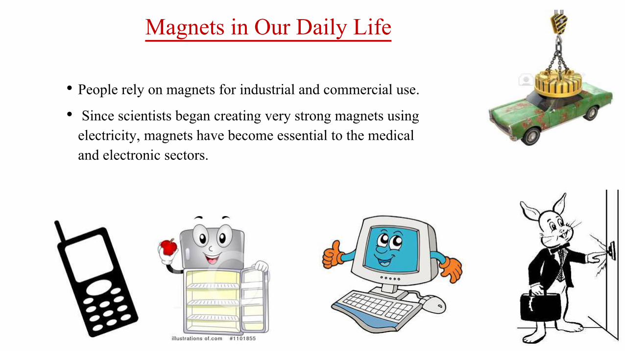
Magnets in Our Daily Life
• People rely on magnets for industrial and commercial use.
• Since scientists began creating very strong magnets using electricity, magnets have become essential to the medical and electronic sectors.

Magnets in Health and Medicine
• Magnets are found in some commonly used medical equipment such as X-rays and MRI machines.
• MRIs use powerful magnetic fields to charge protons in the body.
• The machine monitors the body with a specific radio frequency.
• Some medical practitioners also prescribe magnetic therapy for treatment of a variety of ailments, including arthritis and poor blood flow. In this therapy, patients wear magnets on wrist bracelets, necklaces and in shoe insoles.

Classification of Magnets
1.Natural Magnets
2. Artificial magnets:
Bar magnet
Magnetic needle
Horse shoe magnet
Magnetic compass or Tracing compass
3.The basis of magnetic properties:
Paramagnetic Substances
Ferromagnetic Substances
Diamagnetic Substances
4.Other Classification
Temporary Magnet
Permanent Magnet

Classification of Magnets..1. Natural Magnets:-
Pieces of magnetite are known as natural magnets. About the 12th century people began using these natural magnets, which they called lodestones on leading stones as the first magnetic compasses.
2. Artificial magnets:-
A piece of iron or steel to which attractive and directive properties of lodestone magnetite are imparted, is called artificial magnet.

KINDS OF ARTIFICIAL MAGNETS
• Bar magnet:
• It is a rectangular steel bar, at the ends of which are marked letter N and S.
• The N stands for geographic north and S stands for geographic south.
• Magnetic needle:
• It is a very thin magnetized steel needle mounted on a sharp pivot.
• When suspended freely its ends point in geographic north-south direction.
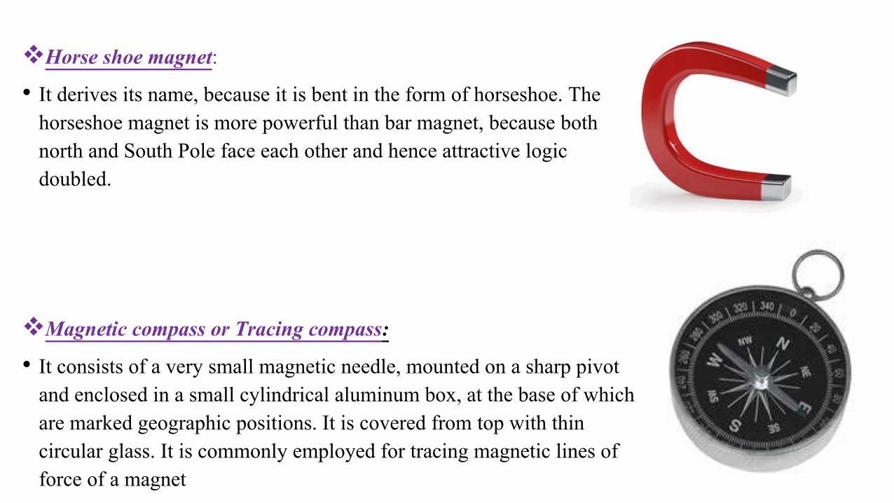
Horse shoe magnet:
• It derives its name, because it is bent in the form of horseshoe. The horseshoe magnet is more powerful than bar magnet, because both north and South Pole face each other and hence attractive logic doubled.
Magnetic compass or Tracing compass:
• It consists of a very small magnetic needle, mounted on a sharp pivot and enclosed in a small cylindrical aluminum box, at the base of which are marked geographic positions. It is covered from top with thin circular glass. It is commonly employed for tracing magnetic lines of force of a magnet

CLASSIFICATION OF SUBSTANCES ON THE BASIS OF MAGNETICPROPERTIES
1. Ferromagnetic Substances: 2. Paramagnetic Substances 3.Diamagnetic Substances
Strongly affected by a magnet can be easily magnetized to form strong
magnetised into three classes.Eg:-Iron, steel, nickel, cobalt and their
alloys
very feebly attracted by a strong magnet.
Eg:-Platinum, manganese. aluminium, zinc, certain kinds of
plastics, wood etc.
feebly repelled by either of the poles of a strong magnet.
Copper, gold, bismuth, antimony, water etc

Other Classifications
• The are made from soft iron• They behave like magnet only as long as there is
inducing magnet.• They can be magnetized to a very high degree
Temporary Magnet
Permanent Magnet
• They are made from steel. • They act as magnet, even on the removal of inducing
magnet. • They cannot be magnetized to a very high degree.
• They have a very poor magnetic retention.


MAGNETISATION
• magnetization or magnetic polarization is the vector field that expresses the density of permanent or induced magnetic dipole moments in a magnetic material.
• Magnetization also describes how a material responds to an applied magnetic field as well as the way the material changes the magnetic field, and can be used to calculate the forces that result from those interactions.
• Physicists and engineers usually define magnetization as the quantity of magnetic moment per unit volume.
• It is represented by a pseudovector M.

METHODS OF MAGNETISATION
Electrical Method Double Touch MethodSingle Touch Method
Direct current flows through a solenoid, a
magnetic field is created.
The more times you rub the permanent magnet over
your ferromagnetic object, the more powerful your temporary magnet will
become
two permanent magnets are taken to magnetize the ferromagnetic material,
operating in opposite directions.

METHODS OF DEMAGNETIZATION
Electrical Method By Heating By Rough Handling
Due to the increased vibrations of the magnetic
particles in the magnet and thus causes them to lose their alignment. and
thus demagnetised.
By hammering magnetic particles in the magnet to lose alignment thus
its magnetism.
Place the magnet in a solenoid connected to and alternating current source and remove the magnet
slowly will demagnetise the piece magnet.

MAGNETIC FIELD
• The space surrounding a magnet within which the magnet has its influence is called magnetic field.
• When there is an electric current flowing there is always a magnetic field.
A static field is formed in the case of direct current, and time varying field is produced by alternating current sourcesSTATIC
TIME VARYING
A time varying magnetic field, which has periodic variations in intensity, induces eddy currents within the body.
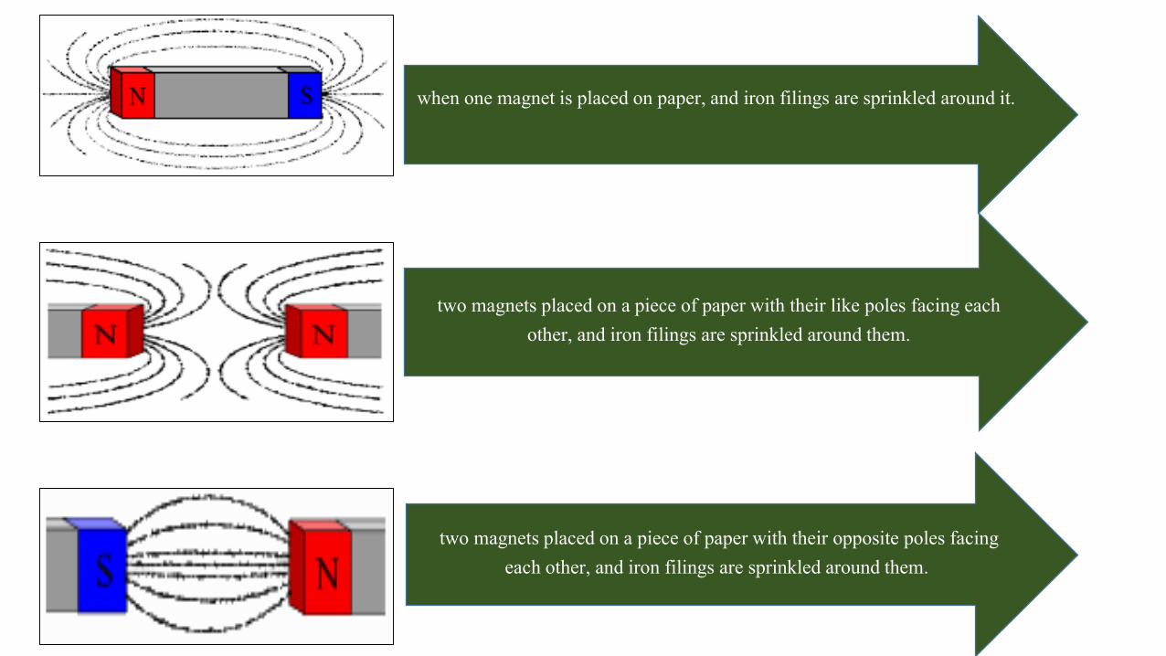
when one magnet is placed on paper, and iron filings are sprinkled around it.
two magnets placed on a piece of paper with their like poles facing each other, and iron filings are sprinkled around them.
two magnets placed on a piece of paper with their opposite poles facing each other, and iron filings are sprinkled around them.

MAGNETIC LINES OF FORCE
the metal sphere is outside the magnet's magnetic field lines. metal sphere on a magnet's field lines near one of its poles.
• The lines that we have mapped out around the magnet, called the magnetic lines of force,

PROPERTIES OF MAGNETS
• All magnets have magnetic fields around them.
• The field emerges from one pole of the magnet conventionally known as the North Pole and returns to the other or South Pole.
• A magnetic field induces changes in the medium surrounding the magnet, such as air. This is called the flux density of the magnet
• The flux produced by the magnets causes them to attract or repel other magnets, and attract other materials containing iron.
• The force produced by any two magnets is inversely proportional to the square of the distance between them.
f α 1/d2
• Thus, the force between two magnets falls dramatically with distance.

COULOMB’S LAW
• All magnets obey this law which states that the force between two magnetic poles is proportional to their magnitudes and inversely proportional to the square of the distance between them.

CURIE POINT Pierre Curie(1859-1906)• Rare earth magnets tend to loss their magnetism at room
temperature.
• Pierre Currie observed that magnets tend to lose their properties if subjected to a specific temperature which causes their domain to return to random distribution.
• This point of temperature is called Currie Point.
• In Orthodontics, this has been overcome by using magnets which are combined with other elements so that they can be incorporated in appliances and also be heat sterilized.

HIGH FORCE TO VOLUME RATIO
• Introduction of new magnetic alloys allowed the use of permanent magnets in dentistry.
• These rare earth magnets, which belong to Lanthinide series, are 20 times stronger than , Aluminium- Nickel - cobalt.
• Thus for the same force magnitude a 20 time smaller magnetic unit can be applied with rare earth magnets because the oral cavity dictates the size of the appliance, the increase in F/V ratio (also known as Miniaturizing Effect)makes the use of magnets in dentistry a beneficial modality.

• Conventional appliances such as coils, springs, elastics etc, react according to Hookes Law, where, force (F) is proportional to a constant such as the elastic modulus(E), time and the distance (d).
• The rare magnets give maximal force at short distance in comparison to elastics, which attain maximum force on more distance for example on mouth opening.

No interruption of magnetic force lines by intermediate media
• Another unique feature of magnetic forces is that any media interposed between two magnets cannot bar the passage of magnetic force lines.
• Intraoral magnets are attracted to each other even if soft or hard tissues arc interposed in the gap between the two magnets
• e.g:- impacted canine.

No friction in attractive force configuration
• Attracting magnets arc useful in controlling the three spatial dimensions.
• This feature is called centripetal orientation.
• When an attractive force configuration is used, friction forces like arch wire in the slot arc excluded. (Darendeliler).
• But in the use of repulsive forces, Muller Prongs guiding elements, arc used for centripetal orientation.
• But these may induce friction in the appliance and may call for increase in force threshold to compensate for the loss from friction. (e.g:- AVC appliance)

NO ENERGY LOSS
• Elastics are the best examples of force systems that deteriorate over a short time.
• The viscoelastic properties of elastics are prone to relaxation.
• In contrast rare earth magnets can maintain energy, if protected against Corrosion, thermal (Curie temperature) and other biologic protuberances.

TYPES OF MAGNETIC MATERIALS
In various dental applications the following materials have been used
Platinum - Cobalt (Pt-Co)
Aluminum -Nickel -Cobalt (AI-Ni-Co)
Ferrite
Chromium- Cobalt -Iron
Samarium Cobalt (Sm Co)
Neodymium-Iron-Boron( Nd2Fe 14B)

• The first three above mentioned magnets were expensive and bulky and were used with their limitations till rare earth cobalt magnets were developed in 1970.
• Finally Samarium Cobalt rare earth magnets were found to be suitable for orthodontic use .
• Iron-Boron was introduced which are 70% more powerful than a same size Sm – Co magnets but are susceptible to corrosion and very brittle.

Samarium-cobalt (SmCo) magnets
• Developed in the 1960s and 1970s.
• Relatively high Curie temperatures, (500-750 degrees ).
• Superior magnetic properties when compared to other rare earth magnets except Neodymium-Iron-Boron magnets.
• It is a powdered, metallurgically processed inter-metallic alloy of cobalt and rare earth metals.
• Even with a flat shape there is hardly any demagnetization making it ideal and small for orthodontic use.

• The force necessary in orthodontics can be obtained from a small sized of the magnet (measurable in millimeters)
• Magnetic properties are invariable in course of time i.e., high - resistance to demagnetization with time.
• Corrosion resistance is high comparatively since they are parylene coated to prevent leaking of toxic substances.
• They can also be encased in stainless steel jackets.
• Hence they are difficult to process but can be filed slightly with dental tools.

NEODYMIUM-IRON-BORON MAGNETS
• A neodymium magnet the most widely used type of rare-earth magnet.
• Neodymium magnets are the strongest type of permanent magnet commercially available
• NEODYMIUM-IRON-BORON MAGNETS produce extremely high magnetic flux densities relative to their size.
• They are accepted as the magnet of choice in orthodontics.

TYPES OF NEODYMIUM-IRON-BORON MAGNETS
most suitable material since it is cheaper & has sufficient resistance to corrosion
Neo 1i
withstand demagnetization at higher temperatures. But poor resistance to corrosion
Neo 3i
Neo 5inewest & most sophisticated. Superior energy production &
resistance to demagnetization

ADVANTAGES
• High energy product value as compared to samarium cobalt magnets
• Better bio compatibility
• High energy product implies stronger forces of attraction

DISADVANTAGES
• Very susceptible to corrosion
• Risk of destroyed magnetic properties and forces
• To avoid liberation of cytotoxic product into the oral cavity it is necessary to coat these magnets with parylene and then embed them into the acrylic blocks

Biological safety of magnets
In vitro Testing to evaluate toxic and carcinogenic effectLevel 1
Testing on animals Level 2
Clinical trialsLevel 3
To evaluate biological safety 3 levels of testing are conducted

Aim of testing biological safety??
EVALUATE THE EFFECT OF STATIC MAGNETIC FIELDS
EVALUATE THE TOXIC EFFECT OF MATERIAL USED AND THEIR CORROSION PRODUCTS

ADVANTAGES OF MAGNETS
• It eliminates patient cooperation, as it is totally operator controlled.
• It produces less pain & discomfort.
• Continuous force is exerted.
• Treatment time is reduced.
• Magnetic tooth movement is biologically more acceptable with reduced periodontal disturbance, root resorption and caries.
• No friction.
• Appliance adjustments are minimal; therefore it takes less chair time.
• Better force, working range control is achieved by maintaining the distance between magnets.
• Better directional force control

• Magnets suffer significantly from tarnish and corrosion.
• Tarnish and corrosion products are cytotoxic.
• Concerns have been expressed on the bioeffects of static magnetic fields.
• Bulk of magnets is still a concern in space limiting applications.
• Cost is also an unfavorable factor.
• Bitterness.
DISADVANTAGES OF MAGNETS

LOCAL EFFECTS WHOLE BODY EXPOSURE
(SYSTEMIC EFFECTS)
EFFECTS OF MAGNETS

Whole body exposure(Systemic Effects)
• Peter neurath(1974): observed no toxic effects by exposing animals to magnetic field strength of coercive force of 108 oersted/cm2.
• WHO reports(1993): suggests that static magnetic fields up to 2T shows no significant health effects However short term exposure to static fields greater than 5T may produce detrimental health effects.
• Cerny(1979) : SmCo magnets have no effects on blood cells
• Blechman(1985) : No increase in urinary Cobalt levels measured at 6 months interval

• Kawata(1987) : No significant changes in Ascorbic acid,and Citric acid concentrations in blood( but after application of force by conventional orthodontic treatment there is decrease in blood and adrenal gland concentration of Ascorbic acid and it is related to stress
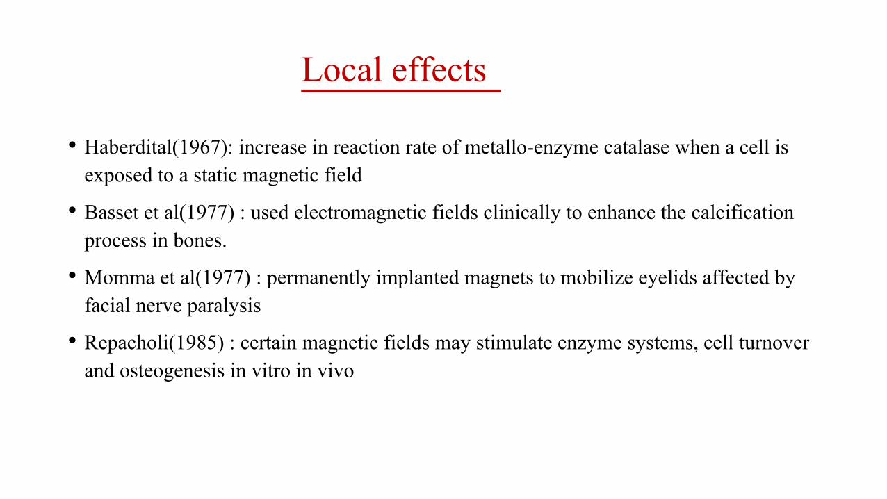
Local effects
• Haberdital(1967): increase in reaction rate of metallo-enzyme catalase when a cell is exposed to a static magnetic field
• Basset et al(1977) : used electromagnetic fields clinically to enhance the calcification process in bones.
• Momma et al(1977) : permanently implanted magnets to mobilize eyelids affected by facial nerve paralysis
• Repacholi(1985) : certain magnetic fields may stimulate enzyme systems, cell turnover and osteogenesis in vitro in vivo

MAGNETIC FORCE SYSTEMS IN
ORTHODONTICS

• This invention involves the orthodontic movement of live teeth in the mouth by using the forces of magnets.
• A magnet is attached to the teeth by conventional methods such as adhesive bonding or dental appliances.
• The magnets are placed on the teeth in such a manner to employ the attraction and repulsion characteristics of a magnetic field

• The magnets may be attached anywhere on a tooth, but preferably in an inconspicuous position.
• The magnets themselves may have tapered edges to insure the teeth move to the proper position.
• In the movement of a single tooth normally a magnet will be attached to the single tooth with the other magnet which creates the repulsion or attraction force being attached to several teeth in combination.

• Relocating impacted teeth (Vardimon et al 1991)
• Expansion of arch (Alexander, in 1987)
• Distalization / mesialisation of teeth (Anthony Gianelly & others, 1988)
• Class II correction with functional appliance (Ali Darendeliler, 1993)
• Intrusion of posterior teeth in open bite cases (Delligner,1986)
• Closure of diastema (Muller, 1984)
• Uprighting and derotation of teeth
• Extrusion of fractured teeth (Bondemark and Kurol, 1997)
Magnetic force delivery systems are now popularly used for;

RARE EARTH MAGNETS AND IMPACTION
• The cause of impaction, in particular of the palatally impacted maxillary canine, is related to aberration in the eruption process, and not due to arch length deficiency.
• Thus a shorter root of the upper lateral incisor frequently can cause palatal impaction of the upper canine because of a lack of guidance.
• This calls for the application of a therapeutic procedure by which the normal eruption mechanism can be simulated.
Vardimon AD1, Graber TM, Drescher D, Bourauel C

• Conventional traction methods have been found to be associated with gingiva inflammation, bone recession, reduced attached gingiva, periodontal pockets, exposed cementoenamel junction, and root resorption of the impacted and adjacent teeth.
• Magnetic traction can avoid these side effects.
• The use of two attracting magnets in the treatment of uneruptedteeth was described by Sadler, Meghji and Murray ( BJO 1989).
• One magnet was bonded to the impacted tooth, while a second stationary magnet was incorporated in a removable acrylic appliance.
• The location of the stationary magnet decided the direction of force.
• Activation was done by repositioning the magnet on the plate occlusally.
Vardimon AD1, Graber TM, Drescher D, Bourauel C

• Vardimon et al (AJO-DO 1991) introduced a magnetic attraction system, with a magnetic bracket bonded to an impacted tooth and an intraoral magnet linked to a Hawley type retainer.
• Vertical and horizontal magnetic brackets were designed, with the magnetic axis magnetized parallel and perpendicular to the base of the bracket, respectively.
• The vertical type is used for impacted incisors and canines, and the horizontal magnetic bracket is applied for impacted premolars and molars.
Vardimon AD1, Graber TM, Drescher D, Bourauel C

• In deep impaction, the Nd2Fe14B magnetic bracket was cold-sterilized before surgery, and the surgical flap was then sutured over the bonded magnetic bracket.
• Attraction was initiated 1 to 2 weeks after healing. Thus tooth emergence into the oral cavity replicated normal eruption conditioning.
• The system operated at an attractive force level of 0.2 to 0.5 N.
• No side effects were observed in a restricted number of treated cases, and treatment time was reduced.
Vardimon AD1, Graber TM, Drescher D, Bourauel C

Advantages
• Better rapport with the patient.
• No manipulation of wires, springs or elastics.
• Since a palatal force is possible, health of the labial cortical plate and zone of attached gingiva are optimized in buccally erupting canines.
• Can be used in molar and premolar impactions.
• Less adjustments required, less pain to the patient.
• 3 D control over the erupting tooth.
• The stationary magnet on the plate can be placed eccentrically with respect to the intra-oral bracket, to produce normal eruption and less need for uprighting the tooth later.
• As the magnet is completely sealed off from the oral cavity, there is no chance of inflammation or infection. Also, normal alveolar bone levels and epithelial attachment are maintained.
Vardimon AD1, Graber TM, Drescher D, Bourauel C

Expansion of arch (Alexander, in 1987)
• Vardimon et al was the first to investigate the use of magnets to provide the force for maxillary expansion.
• The study compared the effects of magnetic versus mechanical expansion with different force thresholds and points of force application.
• The authors demonstrated orthopaedic changes with magnetic palatal expansion.
• The palatally pinned magnetic appliance induced bodily tooth movement, the greatest increase in intermolar distance and a superior repositioning of the maxillopalatine region

• Darendeliler et al examined the effect of magnetic forces for maxillary expansion in human patients of different ages.
• Two types of magnetic expansion device (MED) were used, bonded in two patients and banded in four other patients.
• Two repelling samarium-cobalt magnets were used to generate forces between 250 and 500 grams.
magnetic expansion device (MED)

MOLAR DISTALISATION
• Several authors have reported on the use of magnets to move molars distally.
• In 1988 Gianelly et al described a new intra-arch method, where by distalisation of maxillary first molars was achieved with repelling magnets in combination with a modified Nance appliance cemented on the premolars.
• The molars were distalised at a rate of 0.75-1mm per month, without significant anchorage loss.
• Molar movement was reported to be faster by at least 1mm/month in the absence of second molars and resulted in less anchorage loss.

EXTRUSION OF FRACTURED TOOTH
• Bondemark (1997)-
Magnet Design
• The magnetic system consisted of either one or two cylindrical parylene- or stainless steel-coated, neodymium-iron-boron magnets placed in the coronal part of the remaining root.
• Attractive magnets have been used for orthodontic extrusion.

• The magnets were fixed in the root with a thin layer of composite.
• The use of magnets to extrude a traumatised incisor and enhance root eruption was reported by McCord and Harvie.
• The case report detailed the use of SmCo magnets to extrude the root of an incisor with a subgingival fracture.
• One magnet was fixed to the root and one embedded in a removable partial denture.
• Bondemark et al.reported a similar protocol with NdFeB magnets for the extrusion of crown-root fractured teeth.

OPEN BITE
• The first clinical application in this field, the Active Vertical Corrector, was introduced by Dellinger in 1986.
• Bearing posterior repelling magnets, this appliance was considered as an 'energized' bite block removable or fixed, with the aim of achieving intrusion of the posterior teeth by generating 700 grams of force per magnetic unit.
• The author reported that the four cases treated with this appliance showed little tendency towards re-eruption of the molars, but some labial or lingual tipping of the maxillary incisors was observed.
• The appliance was recommended for both adults and children, although a more rapid correction was observed in growing children.

MAGNETS FOR CLOSING DIASTEMAS
• This was reported by Muller (1984) who bonded rectangular magnets (SmCo) delivering 117.5 gms of force of attraction on each maxillary central incisor to close a midline diastema.
• She also mentioned the possibility of bonding the magnets palatally for better esthetics. Absence of friction and no reactivations were needed, which were advantageous

MAGNETIC APPLIANCES
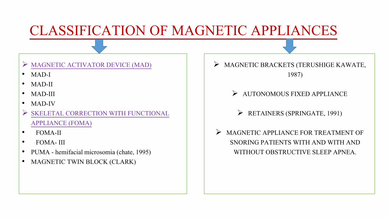
CLASSIFICATION OF MAGNETIC APPLIANCES
MAGNETIC ACTIVATOR DEVICE (MAD)• MAD-I• MAD-II• MAD-III• MAD-IV SKELETAL CORRECTION WITH FUNCTIONAL
APPLIANCE (FOMA)• FOMA-II• FOMA- III• PUMA - hemifacial microsomia (chate, 1995)• MAGNETIC TWIN BLOCK (CLARK)
MAGNETIC BRACKETS (TERUSHIGE KAWATE, 1987)
AUTONOMOUS FIXED APPLIANCE
RETAINERS (SPRINGATE, 1991)
MAGNETIC APPLIANCE FOR TREATMENT OF SNORING PATIENTS WITH AND WITH AND
WITHOUT OBSTRUCTIVE SLEEP APNEA.

MAGNETIC ACTIVATOR DEVICE (MAD)
• This magnetically active functional appliance was developed by darendelelier (1993).
• It can be used for the correction of
• MANDIBULAR DEVIATIONS - (MAD I)
• CLASS II MALOCCLUSION - (MAD II)
• CLASS III CORRECTIONS - (MAD III)
• SKELETAL OPEN BITE CASES - (MAD IV)
• He uses Samarium Cobalt magnets in attractive and repelling mode to achieve orthodontic and orthopedic correction.

MAD II Appliance
• The components of the removable MAD II appliance are:
• An upper and lower Hawley framework carrying a rectangular magnet,on each side in the molar- premolar region.
• A midline magnet, at each incisal edge.
• Two vestibular bows.
• An acrylic occlusal bite plane.
• Adams clasps in the upper premolar areas and modified "C" clasps in the lower molar and bicuspid areas.

• Mechanical retention of the appliances against the magnetic forces is obtained posteriorly by clasps that hook over either molar bands or buttons bonded on the buccal surface of the molars.
• In the anterior area, a small amount of composite is placed on the labial surface of the incisors occlusally to the labial bow, so that the bow rests tightly on its composite support.

• A 30° inclination of the occlusal surface (4 ´ 6 mm) of the magnet to the basal surface (5.2 ´ 4 mm) produces an oblique force vector to correct a Class II malocclusion.
• The 4 mm buccolingual thickness of the magnet is only 1 mm larger than a standard edgewise bracket, and so gives a size and shape compatible with the vestibular shape

• Total magnetic force is 600 to 700 gm
• In Class II cases with normal vertical proportions, the magnets are placed distal to the upper canine and distal to the lower first premolar

• Class II deep bite with magnets in attraction.
• Force direction indicated by arrows.

• Class II open bite situation :- Arrows show dental effects produced by magnets in repulsion and in attraction, probable maxillary and mandibular rotations

MAD III
• A MAD III appliance was constructed from a bonded upper plate and a removable lower plate, each carrying two buccal magnets .
• Two repelling samarium cobalt magnets, each coated with vacuum-molded plastic, were also embedded in the acrylic of the upper plate to form an MED.

TREATMENT OBJECTIVE:
maxillary expansion stimulation of forward
maxillary growth
backward growth modification of mandible
to obtain a dental and skeletal class I
relationship
correction of the crossbitewith a bonded MED while
controlling the dental class III malocclusion
with a mad III appliance.

• Pins and tubes were placed to guide the separation of the palate.
• Only one of the repelling magnets could slide on the pins for activation of the MED.
• Self-polymerizing acrylic was added every three weeks to re-establish contact between the magnets.
• The midpalatal magnets produced 500g of force, which declined to 250g during the three weeks between activations.

• The upper and lower magnets of the MAD III added a total transverse force of as much as 300g (depending on the interocclusal space), for a total expansion force of as much as 800g.
• The lower buccal magnets were placed more anteriorly and buccally than the upper buccal magnets so their attractive force would not interfere with the repulsive force of the midpalatal magnets.
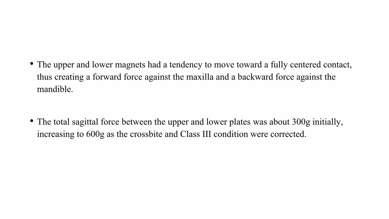
• The upper and lower magnets had a tendency to move toward a fully centered contact, thus creating a forward force against the maxilla and a backward force against the mandible.
• The total sagittal force between the upper and lower plates was about 300g initially, increasing to 600g as the crossbite and Class III condition were corrected.

MAD IV
• The Magnetic Activator Device IV (MAD IV) uses anterior attracting magnets as well as posterior repelling magnets.
• The anterior magnets guide the mandible into a centered-midline position, add an anterior closing effect, and enhance the anterior rotation of the mandible.
• The MAD IV consists of removable upper and lower plates, each of which contains three cylindrical neodymium (Nd2Fe17B) magnets coated with stainless steel .
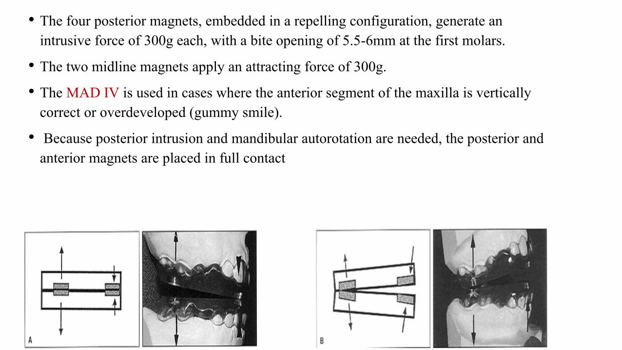
• The four posterior magnets, embedded in a repelling configuration, generate an intrusive force of 300g each, with a bite opening of 5.5-6mm at the first molars.
• The two midline magnets apply an attracting force of 300g.
• The MAD IV is used in cases where the anterior segment of the maxilla is vertically correct or overdeveloped (gummy smile).
• Because posterior intrusion and mandibular autorotation are needed, the posterior and anterior magnets are placed in full contact

• The MAD IV- is used when an additional extrusive effect is needed in the maxillary anterior region. The anterior magnets are positioned with a vertical opening of 2-3mm, while the posterior magnets are placed in full contact
• The MAD IV- is used when only anterior extrusion is needed. The posterior magnets are omitted, and the anterior magnets are placed with an opening of 1-2mm, depending on the severity of the anterior open bite

Functional orthopedic magnetic appliance (FOMA) II
• Vardimon, (1989) introduced a new functional appliance to correct Class lldentoskeletal malocclusions.
• The functional orthopedic magnetic appliance (FOMA) ll uses upper and lower attracting magnetic means (Nd2Fe14B) to constrain the lower jaw in an advanced sagittal posture.

Appliance design
• The lower magnetic housing was incorporated into the lower plate on the dental model. Both upper and lower plates were then bonded to the dental arches.

• The upper magnet was subsequently intraorally attached to the upper plate while the lower jaw was maintained in 3-4 mm advancement and with the two magnets fully superimposed with no air gap.
• Although statistically not feasible because of the small sample, the mandibular elongation (Pg'-Co) increased by 22% in the FOMA II and by 28% in the combined FOMA II + FA over the conventional FA.

Functional orthopedic magnetic appliance (FOMA) III
• Vardimon, 1990 developed an intraoral intermaxillary appliance for the treatment of Class lll malocclusions that exhibit midface sagittal deficiency with or without mandibular excess.
• FOMA III consisted of upper and lower magnetic plates in an attractive force configuration bonded to each respective arch

• The arch wire was embedded in a molded resin sheet overlying the incisor and molar crowns, and formation was completed in a vacuum-forming machine.

• The upper magnetic housing was attached to a retraction screw .
• The lower magnetic housing was permanently attached to the plate in maximal proximity to the lingual surface of the central incisors.
• Reactivation was accomplished by periodic (3 to 4 weeks) posterior repositioning of the upper magnet.

• Major advantages of a FOMA III in comparison with Class III elastics are maximum force at minimum distance (closed mouth) and a sagittal movement (shearing force) at the end of the attractive pathway for spatially displaced magnets to terminate at a maximal overlap of unlike poles (maximal magnetic interface).
• Inclining of the magnetic interface at 15° to the occlusal plane a horizontal force vector of about 100 gm and a vertical force vector four times greater were produced.

FIXED MAGNETIC APPLIANCE
• A fixed magnetic appliance was introduced by Varun Kalra and Charles' Burstone(1989).
• The appliance consists of an upper and a lower acrylic splints with Samarium Cobalt magnets in stainless steel casting embedded in them in the repelling mod

Hypotheses of study
• There were two hypothesis for this study.
1) if all erupted teeth in the upper and lower arches could be intruded with an appliance, the mandible would auto-rotate upward and forward into the interocclusal space created.
2) if this appliance could displace the condyle downward and forward, away from the posterior part of the glenoid fossa, stimulation of condylar growth might occur.
• Both these effects, an increase in length of the mandible and an upward and forward autorotation of the mandible, would be beneficial in treating class II malocclusions associated with increased lower facial height and a retrusive mandible.

Appliance design
• Working bite was taken with the mandible in centric relation.
• Opened 7 to 8mm in the permanent first molar region.
• Upper and lower acrylic splints that were bonded on the occlusal halves of the permanent first molars, deciduous molars or premolars, and canines.
• Samarium cobalt magnets measuring were placed in a stainless steel case 0.007- inch thick and embedded into the upper and lower acrylic splints in a repelling mode.

• In addition 0.028 inch wire was embedded in the acrylic
• This wire rested on the lingual surfaces of the four permanent incisors and was individually bonded to them; thereby intrusive forces were transmitted to the entire arch.
• A fixed appliance was designed that hinged the mandible open and exerted an intrusive force on the teeth.

TREATMENT OBJECTIVES
An increase in length of the mandible
Intrusion of teeth
Upward and forward autorotation of the mandible
Reduction of A-B to occlusal plane
Improvement in the angle of facial convexity
Creation of temporary buccal crossbite caused by the shearing force of repelling magnets.

AUTONOMOUS FIXED APPLIANCE
• A class II bimaxillary protrusion case, were treated with magnets, was reported by Darendeliler and Joho (1992).
• He used upper and lower magnets of Sm-Co bonded to the individual teeth at appropriate level forming the autonomous fixed appliance.
• The individual magnets delivering a force of 20-30 gms, closed all the diastemaspresent.
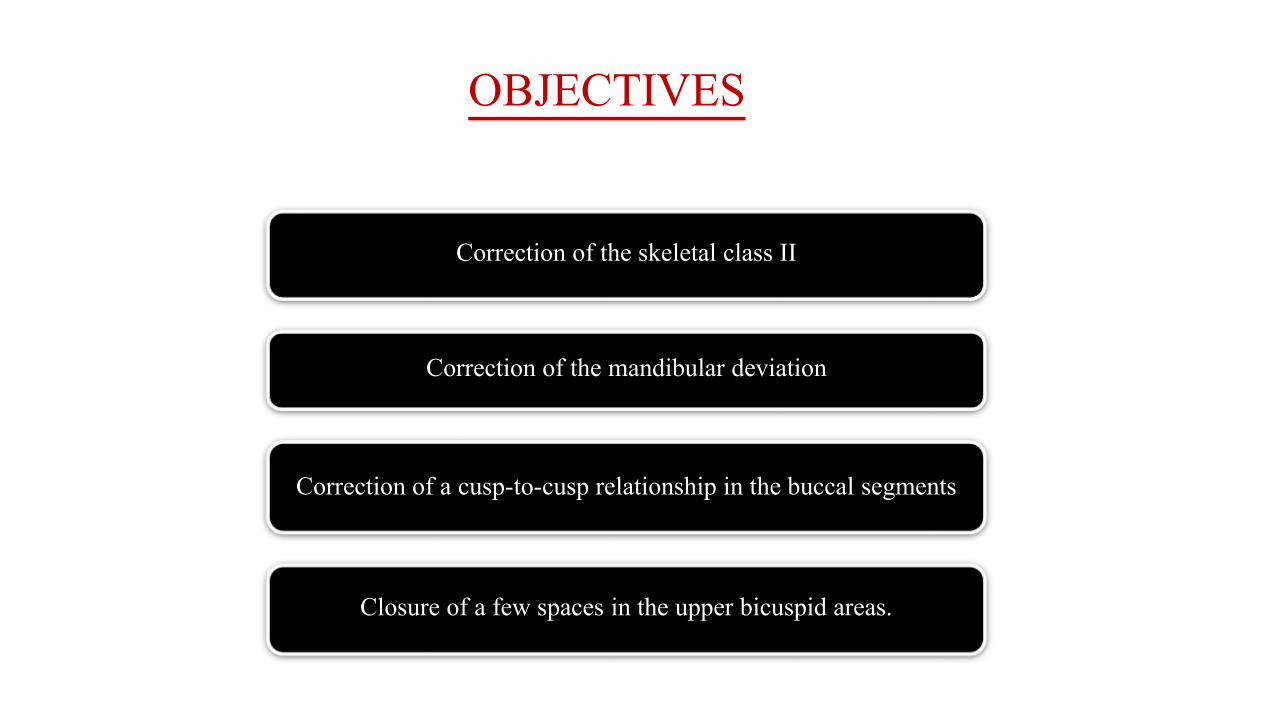
OBJECTIVES
Correction of the skeletal class II
Correction of the mandibular deviation
Correction of a cusp-to-cusp relationship in the buccal segments
Closure of a few spaces in the upper bicuspid areas.

MAGNETIC TWIN BLOCK
• Clark used SmCo & NdFeB in his Twin block. The magnets were embedded in the inclined surface of the Twin blocks.
• In attractive mode they ensured the Twin blocks are always in contact even at night.
• When used in repelling mode it reduces the need for reactivation by inducing additional forward posture of mandible.

The propellant unilateral magnetic appliance (PUMA):
• Chate (EJO,1995) introduced a new technique for hemifacial microsomia.
• Used for stimulating the autogenous costochondral graft.
• Consists of SmCo magnets embedded in upper & lower acrylic bite blocks in repelling mode.
• The long axis of the magnets are perpendicular to blocks interface. Encouraging results were reported.

Appliance design
• This involved unilateral blocks of acrylic, in separate upper and lower removable appliances, with 5 X 5 mm cylindrical gold-plated Samarium Cobalt magnets.
• The upper component had a screw to mechanically advance the block O.25mm sequentially and once fully opened this entailed the fabrication of a new appliance.
• upper block was advanced, the lower was propelled antero-medially, as the mandible pivoted around the normal temporomandibular joint.
• Treatment with the PUMA also resulted in improvement of the lower dental midline, as well as the production of an ipsilateral open bite.
• This was probably due to the unilateral magnetic blocks interrupting the vertical dentoalveolar development and simulating the growth of the graft.

A magnetic appliance for treatment of snoring patientswith and without obstructive sleep apnea• Bernhold, Bondemark (1998): Socially handicapping
snoring with and without obstructive sleep apnea (OSAS) is common and has attracted significant attention in the past 20yrs.
• During sleep, when the masticatory muscles are physiologically relaxed, there is an obvious risk that the mandibular complex moves backward and closes the air flow in the upper airway space.
• In such situations, a magnetic appliance may be more effective than the conventional passive functional appliance, because the magnet forces prevent the closing by providing direct and continuous mandibular advancement.

Appliance Design• Two intraoral removable occlusal splints with full tooth coverage, one in the maxilla
and one in the mandible, were fabricated from transparent acrylic.
• Full tooth coverage is necessary to prevent unwanted orthodontic tooth movements.
• The total height of the two splints together was between 14 and 18 mm, and the plane between the splints was inclined sagittally 10° to 15° to produce an oblique force vector for favoring forward advancement of the mandible.
• In each splint, four parylene coated (poly-para-xylene 250 mm) NIB magnets were embedded.

• The treatment had no aberrant effects of the TMJ status.
• During the use of the magnetic appliance, the mandible rotated downward and backward and the backward rotation mostly camouflaged the sagittal forward movement of the mandible.
• There was no significant influence on the hyoid bone position, but the hypopharyngealairway space increased, the tongue base was lowered and the contact between the tongue and soft palate was reduced significantly.

MAGNETIC BRACKETS
• Kawata et al, in brief, introduced magnetic brackets, in 1987.
• The magnet was coated with Nickel and chromium to prevent corrosion.
• They were designed to deliver 250 gm of force and to form an ideal arch in both maxilla and mandible on completion of treatment.

• The advent of Sm-co magnet which could be fabricated to minimal size yet delivers sufficient force for tooth movement was then responsible for design of a magnetic bracket because of high energy product, resistance to outer demagnetizing fields and suited to a flat circuit.
• Improved Sm-co magnet can deliver a force of 250 gm compared to 50 gm of older magnet. At the same time, the volume of material decreased.
• This force magnitude is sufficient to move canines and other teeth.

Advantages
• Works effectively
• Less discomfort
• Less stress for patient
• Shorter treatment time when compared to traditional appliance.
• Decreased incidence of periodontal problem, root resorption and caries.
• The magnetic force produces a piezo-electric current, which will remodel alveolar bone.

Disadvantages
• Increased cost over traditional brackets
• Magnetic force is not sufficient to move teeth, which are more than 3 mm apart.

MAGNETIC RETAINER
• Springate (1991) used micro-magnets made of Neodymium-Iron-Boron- as a fixed retained palatally in a patient with persistent midline spacing.
• No hindrance in maintaining oral hygiene was an added advantage to this successful treatment.
RECYCLING
• Bondemark & Kurol conducted extensive studies of rare earth magnets used in orthodontics.
• They concluded that recycling does not affect the biocompatibility & the force stability of magnets even though the recycling process involved autoclaving.
• They also recommend that new partially encased SmCo magnets be stored in water for 24 hrs before use to reduce the release of cytotoxic components.
• However Darendililer felt that magnets should not be recycled for ethical reasons & also because they demagnetize during recycling process.

Conclusion
• Even though the magnets in various modalities give a promissory result , research studies are required to evaluate long term stability especially in open bite & class III cases.
• We always desire safe, simple and rapid techniques to achieve therapeutic objectives. Rare earth magnets provide an innovative thought but still further investigation is required to probe in to the biological effects of magnets

REFERENCES• 1. Aronson, S. Sten-Lindskog: A morphometric study of bone surface and skin reaction after stimulation with
magnetic field Am. J. Orthod 44,1991
• 2. Behran, S.l. Egan, G.: Implantation of magnets in the jaw to aid denture retention. J .Prosth Dent. 10:807-84, 1953
• 3. Blechman, A.M.: Magnetic force system in orthodontics. Clinical result of a pilot study. AmJ.Ortho.87:201,1985.
• 4. Blechman, A.M, Smiley, H.: Magnetic force in orthodontics Am.J.Orthod. 74:435,1978
• 5. Cerny, R.: The biological effect of implanted magnetic fields part-I. Mammalion blood cells. Aust. Orthod. 6:64-70, 1979
• 6. Cerny, R.: The biological effect of implanted magnetic fields part-II. Mammalion tissue. Aust. Orthod. J.6:114-7,1980.
• 7. Dellinger, E.L.: A clinical assessment of active vertical 'corrector: A non surgical alternative for skeletal open bite treatment. Am. J. Orthod,. 89:428,1986.
• 8. Gianelly, A.A., Vaitas., A.S. Thomas, Distalization of molars with repelling magnets J.Clin. Orthod. 22;1:40, 1988
• 9. Kawata, T., Hirota, K., Sumitanim K. et al: A new Orthodontic force system of magnetic Brackets. Am. J. Orthod. 92:241, 1987.
• 10. Kalra, V., Nanda, R., Burstone, C.J.: effect of a fixed magnetic appliance on the dentofacial complex. Am.J. Orthod. 095:467,1989.


![BASICS OF ORTHODONTICS · 2019-09-11 · 1. An Introduction to Orthodontics Fourth Edition / Laura Mitchell; 2013 2. Contemporary orthodontics / William R. Proffit [et al.] third](https://static.fdocuments.in/doc/165x107/5f0bf1f17e708231d432fea3/basics-of-orthodontics-2019-09-11-1-an-introduction-to-orthodontics-fourth-edition.jpg)