Magneto Static Analysis of a Brushless DC Motor
8
Magnetostatic Analysis of a Brushless DC Motor Using a Two-Dimensional Partial Differential Equation Solver A. KOSTARIDIS, C. SORAS, V. MAKIOS Laboratory of Electromagnetics, Department of Electrical and Computer Engineering, University of Patras, Greece Received 8 January 2000; accepted 2 January 2001 ABSTRACT: A finite element, magnetostatic analysis, of a brushless direct current motor con tainin g non -linear materi als and per manent mag nets is presented. The analys is is perfo rmed with PDEas e TM ,a low cos t, two-di men sio nal partial dif fer ent ial equ ati on sol ver . The descriptor file is remarkably short and easy to understand, enabling students to focus on the application and not on the finite element method. ß2001 John Wiley & Sons, Inc. Comput Appl Eng Educ 9: 93–100, 2001 Keywords: brush less motor mode ling; finite eleme nt metho d; permanent magnets; non- linear materials INTRODUCTION Electrical engineering students are taught the funda- mental equations of electromagnetic field theory early in their academic curriculum, but these equations can be solved only for th ose pr ob lems which have analyt ical solut ion. Nowa days, with the widesp read availability of personal compu ters, it is possible to solve field equations for the rest of the problems via a numerical method. Field simulations help engineering students to understand the interrelation among field quantities, sources and materials in a problem, and to vastly improve their visualization. Among the various numerical methods for solving field equations, the finite element method (FEM) has been known for several decades and applied to almost any kind of problem at both low and high frequencies. In order to exploit its powerful capabilities, students can either write their own code or modify an existing one or use a software package. The first two options are not practical for undergraduate students because they requir e knowledge beyond thei r le vel and considerable amount of time. On the other hand most software packages seem like black boxes since there is no access to the underl yi ng fie ld equations. The pedagogical gap between the source code and soft- ware package options can be smoothed with the aid of PDEase, a scalar finite element based solver of partial differential equations [1]. Any student who is familiar with the differential form of classic field theory can write a short problem descriptor file, specifying the mathematical model and the proper bound ary conditions. The descri ptor file is te xt ba se d wi th a fo rmat very cl ose to us ua l Correspond ence to V . Makios (v.makios@ee. upatras.gr). ß 2001 John Wiley & Sons, Inc. 93
-
Upload
kareem-abdul -
Category
Documents
-
view
224 -
download
0
Transcript of Magneto Static Analysis of a Brushless DC Motor

8/8/2019 Magneto Static Analysis of a Brushless DC Motor
http://slidepdf.com/reader/full/magneto-static-analysis-of-a-brushless-dc-motor 1/8
Magnetostatic Analysis of a
Brushless DC Motor Using aTwo-Dimensional PartialDifferential Equation Solver A. KOSTARIDIS, C. SORAS, V. MAKIOS
Laboratory of Electromagnetics, Department of Electrical and Computer Engineering, University of Patras, Greece
Received 8 January 2000; accepted 2 January 2001
ABSTRACT: A nite element, magnetostatic analysis, of a brushless direct current motorcontaining non-linear materials and permanent magnets is presented. The analysis isperformed with PDEase TM , a low cost, two-dimensional partial differential equation solver. Thedescriptor le is remarkably short and easy to understand, enabling students to focus on theapplication and not on the nite element method. ß 2001 John Wiley & Sons, Inc. Comput Appl EngEduc 9: 93–100, 2001
Keywords: brushless motor modeling; nite element method; permanent magnets; non-
linear materials
INTRODUCTION
Electrical engineering students are taught the funda-mental equations of electromagnetic eld theory earlyin their academic curriculum, but these equations canbe solved only for those problems which haveanalytical solution. Nowadays, with the widespreadavailability of personal computers, it is possible tosolve eld equations for the rest of the problems via a
numerical method. Field simulations help engineeringstudents to understand the interrelation among eldquantities, sources and materials in a problem, and tovastly improve their visualization.
Among the various numerical methods for solvingeld equations, the nite element method (FEM) has
been known for several decades and applied to almostany kind of problem at both low and high frequencies.In order to exploit its powerful capabilities, studentscan either write their own code or modify an existingone or use a software package. The rst two optionsare not practical for undergraduate students becausethey require knowledge beyond their level andconsiderable amount of time. On the other hand mostsoftware packages seem like black boxes since there is
no access to the underlying eld equations. Thepedagogical gap between the source code and soft-ware package options can be smoothed with the aid of PDEase, a scalar nite element based solver of partialdifferential equations [1].
Any student who is familiar with the differentialform of classic eld theory can write a short problemdescriptor le, specifying the mathematical model andthe proper boundary conditions. The descriptor leis text based with a format very close to usual
Correspondence to V. Makios ([email protected]).ß 2001 John Wiley & Sons, Inc.
93

8/8/2019 Magneto Static Analysis of a Brushless DC Motor
http://slidepdf.com/reader/full/magneto-static-analysis-of-a-brushless-dc-motor 2/8
mathematical notation. In addition, this format allowsa problem to be parameterized in terms of variables,enabling thus quick trade-off studies by varying asingle parameter. The descriptor le is solved auto-matically and the results appear in the form of plots asrequested. PDEase has the capability of automatic
mesh generation and mesh renement which helps theuser to focus on the application and not on the niteelement method.
This paper demonstrates the use of PDEase in theanalysis of a brushless DC motor. This is a magneticeld problem with non-linear materials and permanentmagnets. The difcult task of entering the compli-cated geometry of this sample problem is greatlysimplied through the use of a geometric modeler.The descriptor le for this problem is remarkablyshort and easy to understand from a student with noprior magnetic simulation or motor experience.
MAGNETOSTATIC FORMULATION
For static or slowly varying in time (quasi-static)magnetic elds, the eld intensity (H
~) and ux density
(B~
) must obey:
r  H~
¼ J~
ð1Þ
r Á B~
¼ 0 ð2Þ
subject to a constitutive relationship between B~
and H~
for each material. For non-magnetic and soft magneticmaterials this relationship is:
B~
¼ mH~
ð3Þ
while forhard magnetic materials (permanent magnets):
B~
¼ mðH~
þ H~ cÞ ð4Þ
where H~ c is the coercive eld intensity of the
permanent magnet [2]. For isotropic materials themagnetic permeability m is:
m¼
m0 Á
mr ð
5Þ
where mr is its relative permeability and m0 ¼ 4%Â10
À7H/m. If a material is non-linear m is a function of
B otherwise it is a constant.In this paper the elds that satisfy the above
equations will be calculated via the magnetic vectorpotential A
~, dened by the equation:
B~
¼ r  A~
ð6Þ
which always satises (2). For every point of acomputational domain except those inside permanentmagnets, the combination of (1), (3), and (6) implies:
r Â1m
r  A~
¼ J~
ð7Þ
whereas for points inside permanent magnets the cor-responding equation resulting from (1), (4), and (6) is:
r Â1m
r  A~
À H~
c ¼ J~
ð8Þ
Equation (8) is valid for every point in a com-putational domain and for all materials since itincorporates (7) for space regions outside permanentmagnets by simply setting there H
~ c ¼ 0. Thus, theadvantage of using the vector potential formulation isthat equations (1)–(4) which form the mathematicalmodel of theproblem have been combined into a singleequation. In the general three-dimensional case, J
~and
A~
are vectors with three components each. In the two-dimensional case, however, four of these componentsare zero, leaving only the components in the ‘‘outof the page’’ direction, i.e., J
~¼ J(x,y)a
~z and
A~
¼ A(x,y)a~ z . If A is found, B
~and H
~can then be
deduced from (6) and (3) or (4) respectively.
TORQUE CALCULATION USING THEMAXWELL STRESS METHOD
The most important parameter to calculate is often themagnetically produced torque for a given rotor posi-tion and current excitation. For the torque calculationdifferent methods exist. The most frequently usedmethods are those where the torque is calculateddirectly from the magnetic eld solution in the motor.Such methods are the virtual work method, the mag-netizing current method, and the Maxwell stressmethod (MSM). The accuracy of these methodsdepends to a great extend on the accuracy of themagnetic eld calculation. In our case study we willuse the MSM due to its simplicity.
In the MSM the torque is calculated on the basis
of the magnetic eld distribution on a closed surfacein the air gap around the rotor [3,4]. The differentialtorque produced is:
dT ¼12
½ðr~
 H~
Þðn~
ÁB~
Þ þ ðr~
 B~
Þðn~
ÁH~
Þ
À ðr~
 n~ÞðH
~ÁB
~Þ ð9Þ
The torque of the motor is obtained by creating asurface totally enclosing the rotor and integrating the
94 KOSTARIDIS, SORAS, AND MAKIOS
8/8/2019 Magneto Static Analysis of a Brushless DC Motor
http://slidepdf.com/reader/full/magneto-static-analysis-of-a-brushless-dc-motor 3/8
differential torque over that surface. Thus:
T ¼12þ ððr
~Â H
~Þðn
~ÁB
~Þ þ ðr
~Â B
~Þðn
~ÁH
~Þ
À ðr~
 n~ÞðH
~ÁB
~ÞÞdS ð10Þ
In the above equations r~
is the position vector of thepoint of integration and n
~denotes the unit vector
normal to the surface. The torque is considered relativeto the origin of the coordinate system located at thecenter of the stator.
BRUSHLESS DC MOTORS
A brushless DC motor consists of a rotor withpermanent magnets and a stator with windings. Rotormotion is accomplished by generating a revolving
magnetic eld in the stator windings, which interactswith the permanent magnet elds. In fact, the magnets‘‘chase’’ the rotating magnetic eld and the energizedwinding of the stator switches just as the rotor alignswith the stator. The revolving eld is created bysequentially energizing the winding phase pairs. Thewinding phase pairs are energized with current ow ina set sequence to produce the desired direction of rotation. At any instant, two of the three phases areenergized while the third phase is off. This means thatthese motors do not operate directly off a DC voltagesource. The actual excitation is either squarewave orsinewave current waveforms [5].
The most obvious advantage of the brushlessconguration is that brush maintenance is no longerrequired and many problems associated with brushesdo not exist. For example, brushes tend to produceradiofrequency interference and the sparking asso-ciated with them is a source of ignition in inammableenvironments. In addition, brushless motors arepotentially cleaner, faster, less noisy, and more reliablethan induction motors. The rotor losses are very lowand the stator is easily cooled because of the ne slotstructure and the proximity of the outside air. Theirmain disadvantages are: (i) the need for shaft positionsensing; and (ii) increased complexity in the elec-tronic controller.
DEFINITION OF THE SAMPLE PROBLEM
Geometrical Characteristics
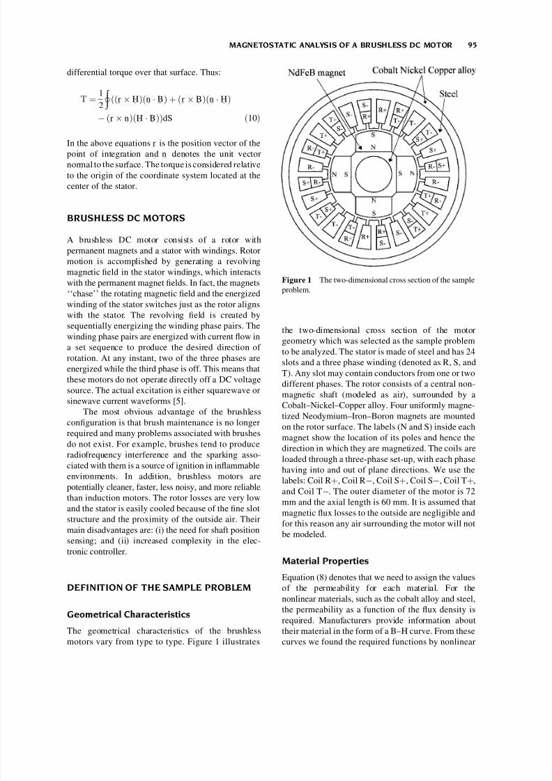
The geometrical characteristics of the brushlessmotors vary from type to type. Figure 1 illustrates
the two-dimensional cross section of the motorgeometry which was selected as the sample problemto be analyzed. The stator is made of steel and has 24slots and a three phase winding (denoted as R, S, andT). Any slot may contain conductors from one or twodifferent phases. The rotor consists of a central non-magnetic shaft (modeled as air), surrounded by aCobalt–Nickel–Copper alloy. Four uniformly magne-tized Neodymium–Iron–Boron magnets are mountedon the rotor surface. The labels (N and S) inside eachmagnet show the location of its poles and hence thedirection in which they are magnetized. The coils areloaded through a three-phase set-up, with each phasehaving into and out of plane directions. We use thelabels: Coil R þ , Coil R À, Coil S þ , Coil S À, Coil T þ ,and Coil T À. The outer diameter of the motor is 72mm and the axial length is 60 mm. It is assumed thatmagnetic ux losses to the outside are negligible andfor this reason any air surrounding the motor will notbe modeled.
Material Properties
Equation (8) denotes that we need to assign the valuesof the permeability for each material. For thenonlinear materials, such as the cobalt alloy and steel,the permeability as a function of the ux density isrequired. Manufacturers provide information abouttheir material in the form of a B–H curve. From thesecurves we found the required functions by nonlinear
Figure 1 The two-dimensional cross section of the sampleproblem.
MAGNETOSTATIC ANALYSIS OF A BRUSHLESS DC MOTOR 95
8/8/2019 Magneto Static Analysis of a Brushless DC Motor
http://slidepdf.com/reader/full/magneto-static-analysis-of-a-brushless-dc-motor 4/8
curve tting. For the Cobalt–Nickel–Copper alloy wewill use the equation:
mðBÞ ¼ 8265 ÁeÀðBÀ0:63Þ13
0:02À ÁÁ 1 Àe
ÀB0:19ð Þ
2:4 !þ 295
ð11 Þ
while for the steel the corresponding equation takesthe form:
mðBÞ ¼5000
1 À 0:05 ÁB 2 þ 200 ð12Þ
In the case of permanent magnets, manufacturersprovide information in the form of a demagnetizationcurve, which lies in the second quadrant of the B–Hplane. This curve indicates the remanent ux densityB r (for H
~¼ 0), the coercive eld intensity H
~c (for
B~
¼ 0), and the manner in which B~
and H~
varybetween these two points. Rare-earth materials, suchas Neodymium–Iron–Boron (NdFeB) magnets, exhi-bit an almost linear demagnetization curve and as aresult the linear model used in (4) is sufcient forproperly modeling them. From a manufacturer of NdFeB magnets datasheet we read B r ¼ 1:16 T,Hc ¼ 883310 A/m which according to:
B~
r ¼ mH~
c ð13Þ
implies a relative permeability equal to 1.045.
PDEase IMPLEMENTATION
The Problem Descriptor File
In PDEase any problem to be solved is specied bymeans of a descriptor, which is simply a programwritten in the command language of the package. Atrst this seems rather cumbersome, but the advantageis that we can program our geometry using variablesand then make changes very rapidly. A problem
descriptor le is divided into sections. Each onedescribes a different type of information needed tospecify the problem and is composed of statements.
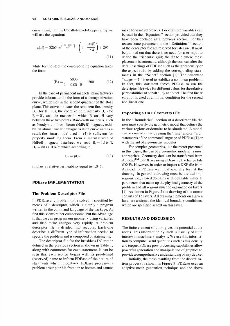
The descriptor le for the brushless DC motordened in the previous section is shown in Table 1,along with comments for each statement. It can beseen that each section begins with its pre-dened(reserved) name to inform PDEase of the nature of statements which it contains. PDEase processes aproblem descriptor le from top to bottom and cannot
make forward references. For example variables canbe used in the ‘‘Equations’’ section provided that theyhave been declared in a previous section. For thisreason some parameters in the ‘‘Denitions’’ sectionof the descriptor le are reserved for later use. It mustbe pointed out that there is no need for user-input to
dene the triangular grid; the nite element meshplacement is automatic, although the user can alter thedefault settings of PDEase such as the grid density orthe aspect ratio by adding the corresponding state-ments in the ‘‘Select’’ section [1]. The statement‘‘stages ¼ 2’’ is used to stabilize a nonlinear problem.In fact, this statement forces PDEase to run thedescriptor le twice for different values for the relativepermeabilities of cobalt alloy and steel. The rst linearsolution is used as an initial condition for the secondnon-linear one.
Importing a DXF Geometry FileIn the ‘‘Boundaries’’ section of a descriptor le theuser must specify the geometric model that denes thevarious regions or domains to be simulated. A modelcan be created either by using the ‘‘line’’ and/or ‘‘arc’’statements of the command language of PDEase [1] orwith the aid of a geometric modeler.
For complex geometries, like the motor presentedin this paper, the use of a geometric modeler is mostappropriate. Geometry data can be transferred fromAutocad
TMto PDEase using a Drawing Exchange File
(DXF). However, in order to import a DXF le fromAutocad to PDEase we must specially format thedrawing. In general a drawing must be divided intoregions, i.e., closed domains with denable materialparameters that make up the physical geometry of theproblem and all regions must be organized on layers[1]. As shown in Figure 2 the drawing of the motorconsists of 15 layers. All drawing elements on a givenlayer are assigned the identical boundary conditions,which are specied as text on this layer.
RESULTS AND DISCUSSION
The nite element solution gives the potential at thenodes. This information by itself is usually of littleinterest in machinery analysis. We use this informa-tion to compute useful quantities such as ux densityand torque. PDEase post-processing capabilities allowpowerful generation and manipulation of graphics toprovide a comprehensive understanding of any device.
Initially, the mesh resulting from the discretiza-tion process is shown in Figure 3. PDEase uses anadaptive mesh generation technique and the above
96 KOSTARIDIS, SORAS, AND MAKIOS
8/8/2019 Magneto Static Analysis of a Brushless DC Motor
http://slidepdf.com/reader/full/magneto-static-analysis-of-a-brushless-dc-motor 5/8
plot is the last and ner grid so that the eld solutionmeets the accuracy requirements specied for thisproblem in the select section of the descriptor le.This nal grid contains 10,369 nodes and 5,106 trian-gular elements. The meshing algorithm also detectsthe ‘‘feature’’ named ‘‘circle’’ and uses it to rene themesh by adding extra nodes along the periphery of the
circle. This allows us to compute the elds in the airgap and the torque more accurately.
Figures 4 and 5 show a contour and surface plotrespectively of the magnetic vector potential A overthe whole model. From these gures it can be seenthat the zero Dirichlet boundary condition that weimposed at the outer surface of the motor is identically
Table 1 Problem Descriptor File
Code Syntax Comment
Title Brushless DC Motor The Name of the ProblemSelect
stages ¼ 2errlim
¼1e-5
ngrid ¼ 50; aspect ¼ 1.5
We request two runs for the non-linear problemRequested relative accuracyParameters to control the mesh density
VariablesA Declare A to be the system variable.
Definitions {S.I. Units}mu0 ¼ 4*pi*1.0e-7mur1 ¼ 1; mur2 ¼ 1.045J1 ¼ 0J2 ¼ 1500000J3 ¼ À1500000murJC ¼ 883310
Hcx ¼ 0; Hcy ¼ 0Hc ¼ vector(Hcx,Hcy)H ¼ curl(A)* (1/(mur*mu0)) ÀHcBxc ¼ dy(A); Byc ¼ Àdx(A)B ¼ vector(Bxc,Byc)Babs ¼ sqrt(Bxc**2 þ Byc**2)muralloy ¼ if stage ¼ 1 then 8265else 8265*exp[ À(Babs À0.63)**13/0.02]*[1À(exp( ÀBabs/0.19)/2.4)] þ 295mursteel ¼ if stage ¼ 1 then 5000else 5000/(1 À0.05*(Babs)**2) þ 200Rho ¼ vector(x,y)dTorque ¼ 1/2*((cross(Rho,H)*(normal(B))) þ(cross(Rho,B))*(normal(H)))
Permeability of free spaceRelative permeability of air and magnets respectivelyCurrent density in coils T þ and T ÀCurrent density in coils R þ and S ÀCurrent density in coils R À and S þRelative permeability parameter reservedCurrent density parameter reservedCoercive eld intensity of NdFeB magnets
Coercive eld intensity componentsCoercive eld intensity vectorMagnetic eld intensity vectorMagnetic ux density componentsMagnetic ux density vectorMagnitude of magnetic ux densityRelative permeability of Cobalt Alloy as a function of ux
density (equation 11)
Relative permeability of steel as a function of ux density(equation 12)
The position vector of the (x,y) pointDifferential torque to be integrated along the air gap
(equation 9)
Equationscurl(H) ÀJ ¼ 0 The magnetostatic equation to be solved Boundaries
dxf_import(Motor ¼ ‘‘motor.dxf’’)feature 16start ‘‘circle’’ ( À0.01745,0) arc(center ¼ 0,0)angle ¼ À360
Importation of the geometry le
Draws a circle around the air gap
Plotscontour(A)surface(A)vector(Bxc,Byc)elevation(normal(B),tangential(B)) on ‘‘circle’’elevation(dTorque) on ‘‘circle’’
Contour plot of the magnetic vector potential ASurface plot of AVector plot of the ux density BBn and Bt along the air gap peripheryThe area under this plot equals the torque per unit of axial
length of the motor
End Declare the end of the descriptor le.
MAGNETOSTATIC ANALYSIS OF A BRUSHLESS DC MOTOR 97

8/8/2019 Magneto Static Analysis of a Brushless DC Motor
http://slidepdf.com/reader/full/magneto-static-analysis-of-a-brushless-dc-motor 6/8
satised. We can also observe the symmetry of thesolution which reects the symmetry of the geometry.The magnetic ux density strength and direction canbe visualized through the use of a vector plot as shownin Figure 6. The vectors show the direction of the uxow and their size show the magnitude. This gureindicates large ux density concentration in the air
gap between the stator and the rotor. It is well knownthat the air gap ux distribution is essential becausethe energy conversion is processed through the airgap. For this reason the normal and tangentialcomponents of the ux density along the air gapperiphery are illustrated in Figure 7.
Finally, Figure 8 shows the differential torquealong the air gap periphery. The area under this plotequals the torque per unit of axial length. To get theactual torque of the motor, this value has to be
Figure 2 The imported geometry in DXF format.
Figure 3 Discretization of the problem geometry. Figure 4 Contour lines of the magnetic potential A (Wb/m).
98 KOSTARIDIS, SORAS, AND MAKIOS

8/8/2019 Magneto Static Analysis of a Brushless DC Motor
http://slidepdf.com/reader/full/magneto-static-analysis-of-a-brushless-dc-motor 7/8
multiplied by its axial length. For the 60-mm longmotor we have:
Torque ¼ 2:959 Nm =m  60 mm
¼ 177 :54 Â 10À3 Nm ð14Þ
To calculate the torque for different angular positionsof the rotor we only have to rotate the rotor assembly(in the dxf le) and then re-execute the descriptor le.It is also possible to radially displace the rotorassembly with respect to the center of the stator, inorder to study the effect of miscentering on the torque.
In this case the third term in equation (9) must also beincluded in the corresponding statement of thedescriptor le since r
~Â n
~is no more zero.
A nal remark concerns the fundamental questionwhether to perform a two- or three-dimensionalanalysis. Though a two-dimensional analysis mayseem less accurate than a three-dimensional one, itactually may yield more accurate results when non-linear materials are present and the end effects are notimportant. Moreover, the time required for a two-dimensional simulation is often about 10% that of thethree-dimensional one and thus the best approach is toperform the analysis and optimization in two-dimen-sional and then check the results in three-dimensional[6]. This validation could be done in FlexPDE
TM[7], a
three-dimensional partial differential equation solver,which uses virtually the same syntax as PDEase.
CONCLUSIONS
In this paper the application of the nite elementmethod for the two dimensional magnetostatic analysisof a brushless DC motor was presented. The analysiswas performed in the PDEase
TMenviroment, a low
Figure 5 Surface plot of the magnetic potential A.
Figure 6 Vector plot of the ux density B.
Figure 7 The normal and tangential components of theux density along the air gap periphery.
Figure 8 The differential torque along the air gap.
MAGNETOSTATIC ANALYSIS OF A BRUSHLESS DC MOTOR 99
8/8/2019 Magneto Static Analysis of a Brushless DC Motor
http://slidepdf.com/reader/full/magneto-static-analysis-of-a-brushless-dc-motor 8/8
cost partial differential equation solver with automaticmesh generation and renement capabilities. Thedescriptor le for this problem is remarkably short andeasy to understand due to its very close to usualmathematical notation syntax. This kind of softwarecan be very benecial to engineering students in order
to strengthen their understanding of eld’s theorydifferential form, boundary conditions, and the role of material properties. Additionally, it can raise student’sinterest and appreciation on abstract mathematicalformulations because they can easily see theirapplication and solution for real world problems. Inthis way they can acquire the solid background neededto use specialized packages.
REFERENCES
[1] PDEase TM , Reference manual, tutorial, Handbook of demonstrations, Macsyma Inc, 1996.
[2] N. Ida and J.P.A Bastos. Electromagnetics and calcula-tion of elds, 2nd ed., Springer, New York, 1997, p.389.
[3] A. F. L. Noqueira, ‘‘Limitations of the ConventionalMethods of Force and Torque Prediction,’’ Journal of ACES, 12(1)(1997), p. 74–79.
[4] M. Trlep, A. Hamler, and B. Hribernik. ‘‘VariousApproaches to Torque Calculations by FEM and BEM,’’Journal of ACES, 12(2)(1997), p. 127–130.
[5] T. J. E. Miller, Brushless permanent-magnet and reluc-tance motor drives. Clarendon Press, Oxford, 1989,p. 55–58.
[6] J. Sabonnadiere and A. Konrad, ‘‘Computing EMFields,’’ IEEE Spectrum, 29(11)(1992), p. 52–56.
[7] FlexPDE TM , PDE Solutions Inc.
BIOGRAPHIES
Vassilios Makios was born in Kavala,Greece. He received his electrical engineer-ing degree (Dipl. Ing.) from the TechnicalUniversity in Munich, Germany, in 1962and the Ph.D (Dr. Ing.) from the MaxPlanck Institute for Plasmaphysics and theTechnical University in Munich in 1966.From 1962 to 1967 he was ResearchAssociate in the Max Planck Institute for
Plasmaphisics in Munich, where he was associated with microwaveinteraction studies on plasmas. He served as Assistant Professor1967–1970, Associate Professor 1970–1979, and Full Professor1973–1977 in the Department of Electronics, Carleton University inOttawa, Canada, where he was involvedwith teaching and research inmicrowave and optical communications, radar technology, remotesensing, and CO 2 laser development. From 1977, he is an HonoraryResearch Professorof Carleton University. From 1976, he is Professorof Engineering and Director of the Electromagnetics Laboratory inthe Electrical Engineering Department of the University of Patras inGreece, where he is involved in teaching and research in microwaveand optical communications, data communications networks,LAN’s, MAN’s, B-ISDN, and ATM technology with emphasis onefcient hardware implementations and rapid prototyping. Hislaboratory is actively participating in EU ACTS & ESPRIT R&Dprojects, e.g., LION, DISTIMA, PANORAMA, COBUCO etc. In1986–1987, he spent his sabbatical year at the R&D laboratories of Siemens in Munich. He is also involved in research in photovoltaticsystems. He has published over 130 papers and numerous patents in
the above elds. He has participated in the organizing committees of numerous IEEE and European Conferences and was the TechnicalProgram Chairman of the 5th Photovoltaic European CommunityConference in Athens, 1983 and Co-Chairman of the EURINFO,1988 Conference of the European Community. He is the recipient of the silver medal (1984) and the golden medal (1999) of the GermanElectrical Engineering Society (VDE). He is a senior member of theIEEE, member of the Canadian Association of Physicists, theGermanPhysical Society, and the VDE, Professional Engineer of the Province
of Ontario and the Greek Technical Chamber. He is currently Deanof Engineering from 1997 to-date and served also as Dean of Engineering in the period 1980–1982. For the past 12 years, he hasserved as the Vice President of the Research Committee of theUniversity.
Constantinos Soras was born in Patras,Greece. He received both his electricalengineering diploma and Ph.D from theUniversity of Patras, Greece in 1981 and1989, respectively. From 1982 to 1989, hewas Research Associate in the Electrical
and Computer Engineering Department of the University of Patras, was involved withphotovoltatic systems performance model-
ing. Since 1991, he has served as Lecturer in the Laboratory of Electromagnetics of the same department. He is teaching the basicelectromagnetic courses and at the senior undergraduate/graduatelevel computational electromagnetics. His current research interestsfocus on computational electromagnetics, printed antennas, indoorradiowave propagation, and photovoltaic systems. He is member of the Technical Chamber of Greece, the International Solar EnergySociety, and the Applied Computational Electromagnetics Society.
Antonios Kostaridis was born in Athens,Greece on 4 September 1976. He receivedhis electrical engineering diploma from
the University of Patras, Greece, in 1999.Currently he is a post-graduate student atthe Laboratoty of Electromagnetics,Department of Electrical and ComputerEngineering of the University of Patras.His research interests include numerical
solutions to electromagnetic radiation and scattering problems,printed antennas, and electromagnetic compatibility. He is amember of the Technical Chamber of Greece.
100 KOSTARIDIS, SORAS, AND MAKIOS