Basic Study for Development of Magneto-rheological Elastomer
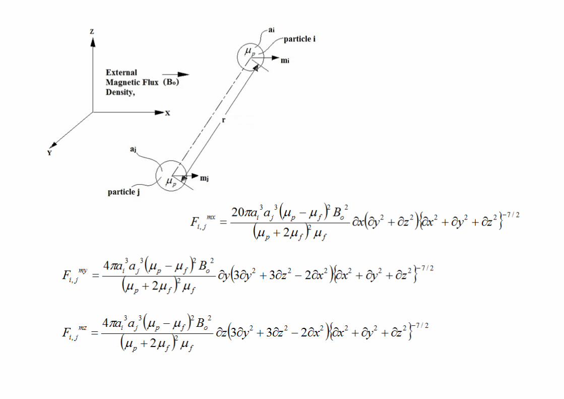
Magneto-Rheological (MR) Fluids
Harish HiraniAssociate ProfessorDepartment of Mechanical EngineeringIndian Institute of Technology DELHI
Lubrication & Bearings http://web.iitd.ac.in/~hirani/
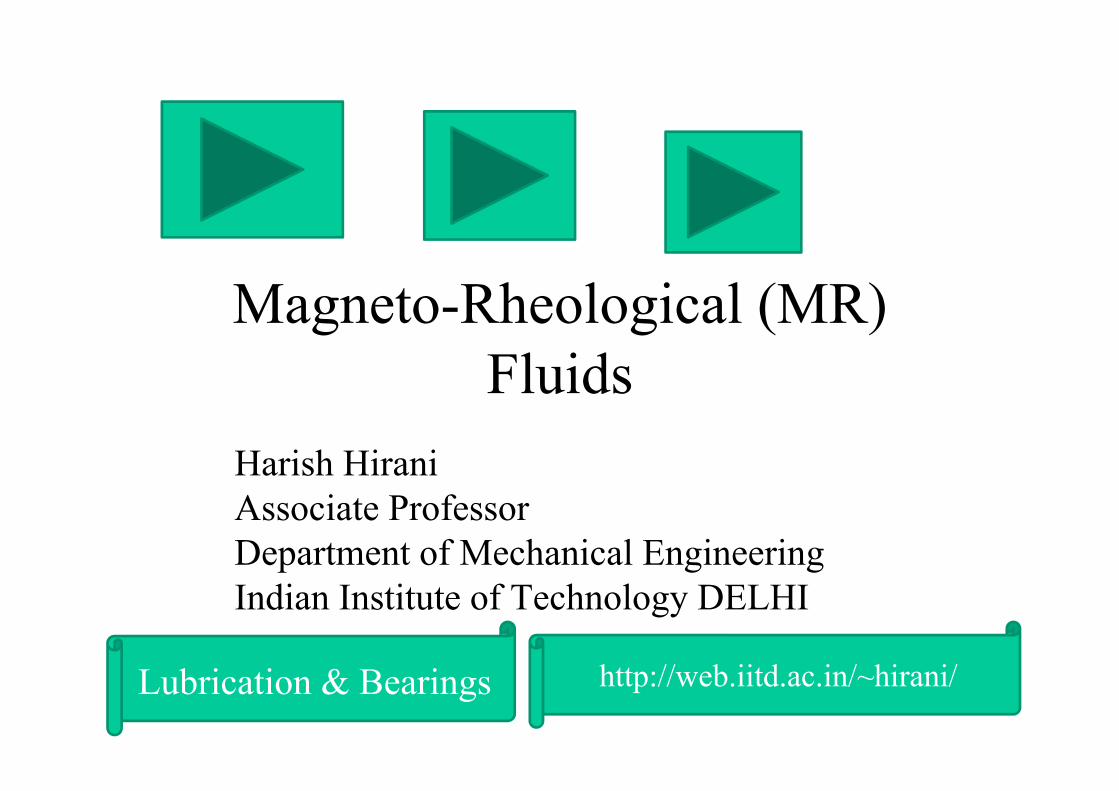
MagnetoRheological Fluids
Dr. H. HiraniMechanical Engnieering, IIT Delhi
Used in Japan's National Museum of Emerging Science & China's Dong Ting Lake Bridge to counteract vibrations caused by earthquakes and gusts of wind
RHEOS (Greek word) = to FLOW (English word)
RheoLOGY= Science of material flow under external load conditions
MAGNETOrheological FLUID= Fluid, whose apparent viscosity increases, with application of MAGNETIC field.
Liquids that harden or change shape when they feel a magnetic field
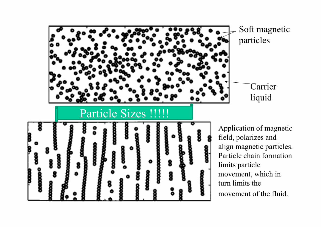
Carrier liquid
Soft magnetic particles
Application of magnetic field, polarizes and align magnetic particles. Particle chain formation limits particle movement, which in turn limits the movement of the fluid.
Particle Sizes !!!!!
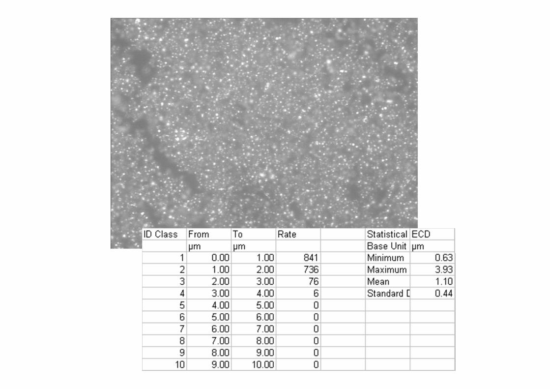
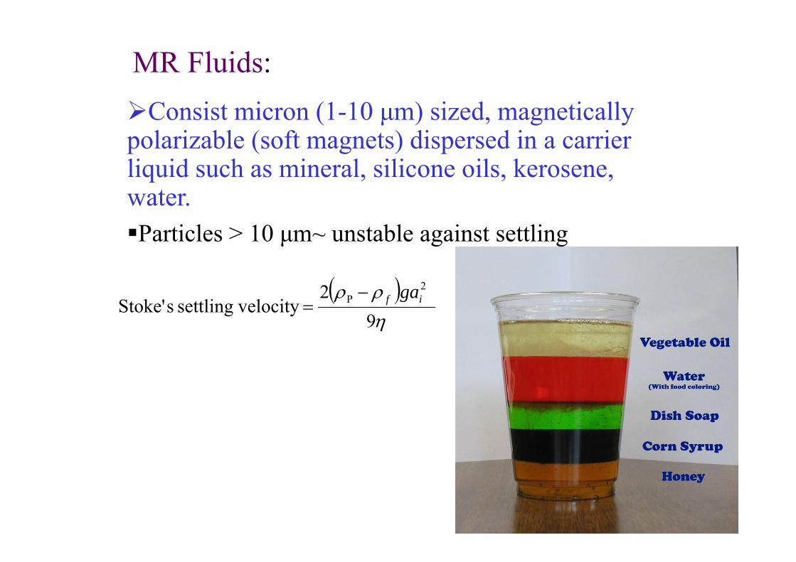
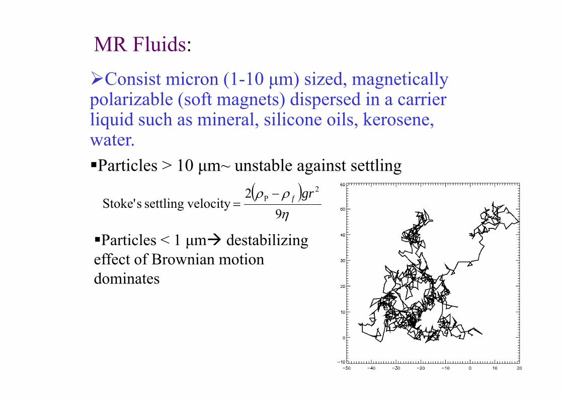
Consist micron (1-10 μm) sized, magnetically polarizable (soft magnets) dispersed in a carrier liquid such as mineral, silicone oils, kerosene, water.Particles > 10 μm~ unstable against settling
MR Fluids:
( )ηρρ
92
velocitysettling sStoke'2
P if ga−=
Consist micron (1-10 μm) sized, magnetically polarizable (soft magnets) dispersed in a carrier liquid such as mineral, silicone oils, kerosene, water.Particles > 10 μm~ unstable against settling
MR Fluids:
( )ηρρ
92
velocitysettling sStoke'2
P grf−=
Particles < 1 μm destabilizing effect of Brownian motion dominates
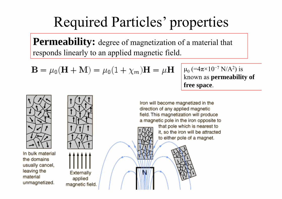
Required Particles’ propertiesPermeability: degree of magnetization of a material that responds linearly to an applied magnetic field.
μ0 (=4π×10−7 N/A2) is known as permeability of free space.
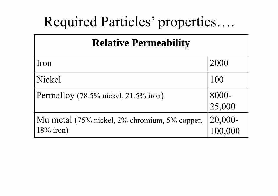
Required Particles’ properties….Relative Permeability
Iron 2000
Nickel 100
Permalloy (78.5% nickel, 21.5% iron) 8000-25,000
Mu metal (75% nickel, 2% chromium, 5% copper, 18% iron)
20,000-100,000

Required Particles’ properties….
Coercivities of soft and hard magnetsMaterial Coercivity
Permalloy, Ni81Fe19 0.5-1
Co 20
Ni 150
Alnico, a common refrigerator magnet 1500-2000
NdFeB 10,000
SmCo5 40,000
The applied field where the data (called a magnetization curve) crosses zero is the coercivity.Saturation Limit: The limit of applied field at which all the magnetic domains align with the field, and the magnetic-curve flattens out.
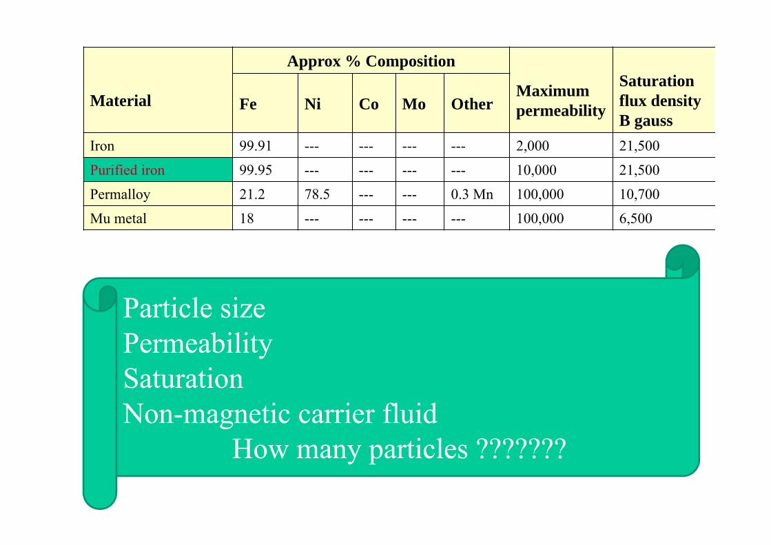
Material
Approx % Composition
Maximum permeability
Saturation flux density B gauss
Fe Ni Co Mo Other
Iron 99.91 --- --- --- --- 2,000 21,500
Purified iron 99.95 --- --- --- --- 10,000 21,500
Permalloy 21.2 78.5 --- --- 0.3 Mn 100,000 10,700
Mu metal 18 --- --- --- --- 100,000 6,500
Particle sizePermeabilitySaturationNon-magnetic carrier fluid
How many particles ???????
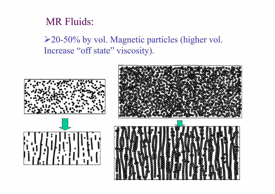
MR Fluids:
20-50% by vol. Magnetic particles (higher vol. Increase “off state” viscosity).

0
20
40
60
80
100
120
140
0 20 40 60 80 100 120 140
Yie
ld S
tress
(kPa
) at
100
(1/s
)
Magnetic Field, H (kA/m)
MRF36L
MRF36S
MRF36M1
MRF36M2
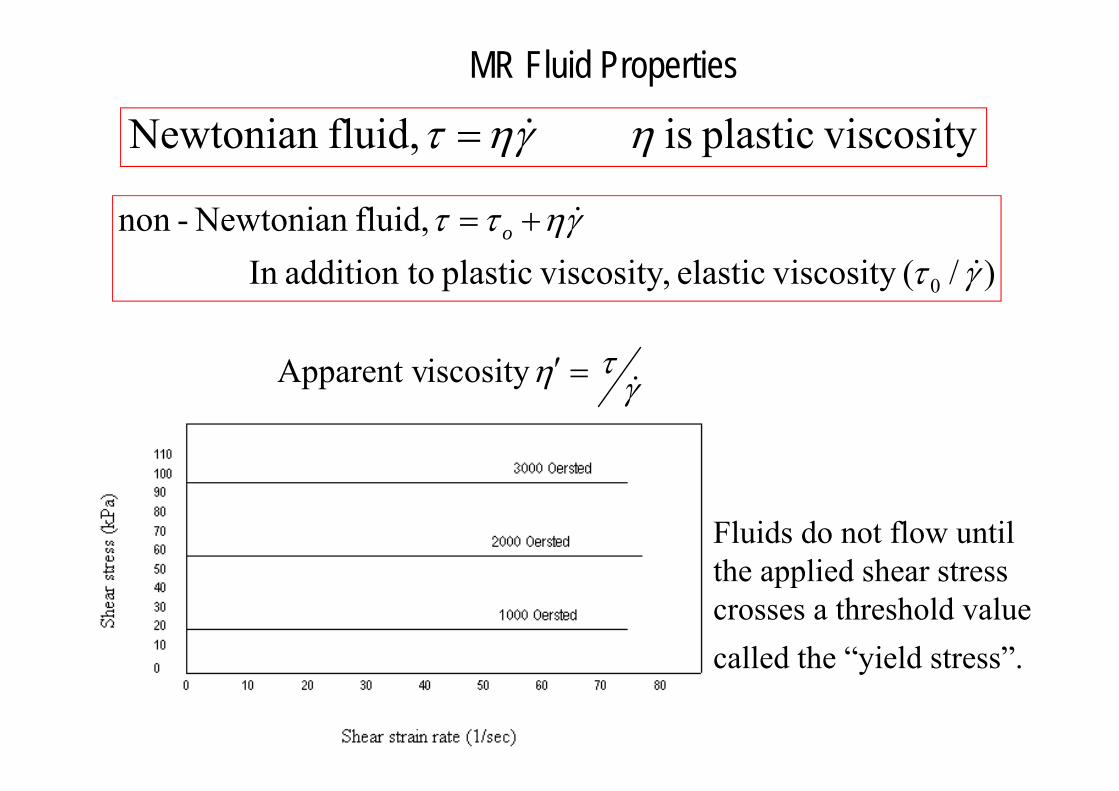
MR Fluid Properties
)/( viscosityelastic , viscosityplastic oaddition tIn fluid,Newtonian -non
0 γτγηττ
&
&+= o
viscosityplastic is fluid,Newtonian ηγητ &=
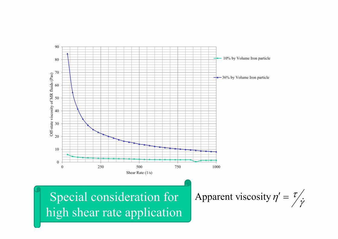
Fluids do not flow until the applied shear stress crosses a threshold value called the “yield stress”.
γτη &=′iscosity Apparent v
0
10
20
30
40
50
60
70
80
90
0 250 500 750 1000
Off
-sta
te v
isco
sity
of M
R fl
uids
(Pas
)
Shear Rate (1/s)
10% by Volume Iron particle
36% by Volume Iron particle
γτη &=′iscosity Apparent vSpecial consideration for
high shear rate application
MR-FLUID…………..Make device smart by changing system’s properties( stiffness, damping, viscosity, shear modulus) in a desirable manner. Sy ~ 0-100 kpa
Useful in active control of vibration & motion, i.e. engine mount, shock absorbers, seat dampers, variable resistance equipment, etc.
Motion damping is perhaps the most practical use for MR technology today

Property MR fluids ER fluidsMax. yield stress τ0 50-100 kpa 2-5 kpa
Maximum field ~250 kA/m ~4 kV/mm
Apparent plastic viscosity η 0.1-10 pa-s 0.1-10 pa-s
Operable temp. range -40-150 oC +10-90 oC
Stability Unaffected by most impurities
Cannot tolerate impurities
Density 3-4 g/cm3 1-2 g/cm3
Maximum energy density 0.1 Joules/cm3 0.001 Joules/cm3
Power supply (typical) 2-50 V, 1-2 A 2000-5000 V, 1-10 mA
MR Fluids:20-50 times stronger than ER fluids, lower
sensitivity to impurities.
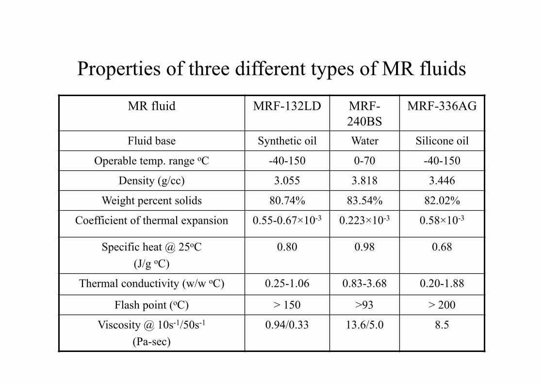
MR fluid MRF-132LD MRF-240BS
MRF-336AG
Fluid base Synthetic oil Water Silicone oil
Operable temp. range oC -40-150 0-70 -40-150
Density (g/cc) 3.055 3.818 3.446
Weight percent solids 80.74% 83.54% 82.02%
Coefficient of thermal expansion 0.55-0.67×10⁻³ 0.223×10⁻³ 0.58×10⁻³
Specific heat @ 25oC(J/g oC)
0.80 0.98 0.68
Thermal conductivity (w/w oC) 0.25-1.06 0.83-3.68 0.20-1.88
Flash point (oC) > 150 >93 > 200
Viscosity @ 10s-1/50s-1
(Pa-sec)0.94/0.33 13.6/5.0 8.5
Properties of three different types of MR fluids
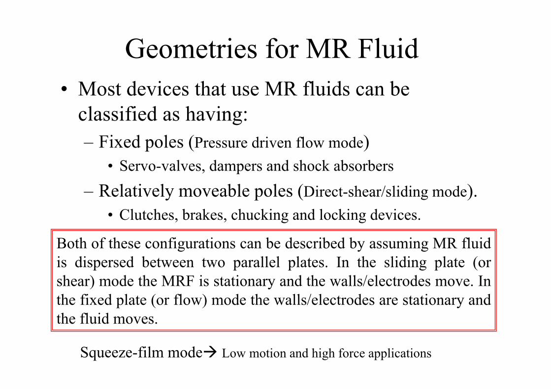
Geometries for MR Fluid• Most devices that use MR fluids can be
classified as having:– Fixed poles (Pressure driven flow mode)
• Servo-valves, dampers and shock absorbers
– Relatively moveable poles (Direct-shear/sliding mode). • Clutches, brakes, chucking and locking devices.
Both of these configurations can be described by assuming MR fluidis dispersed between two parallel plates. In the sliding plate (orshear) mode the MRF is stationary and the walls/electrodes move. Inthe fixed plate (or flow) mode the walls/electrodes are stationary andthe fluid moves.
Squeeze-film mode Low motion and high force applications
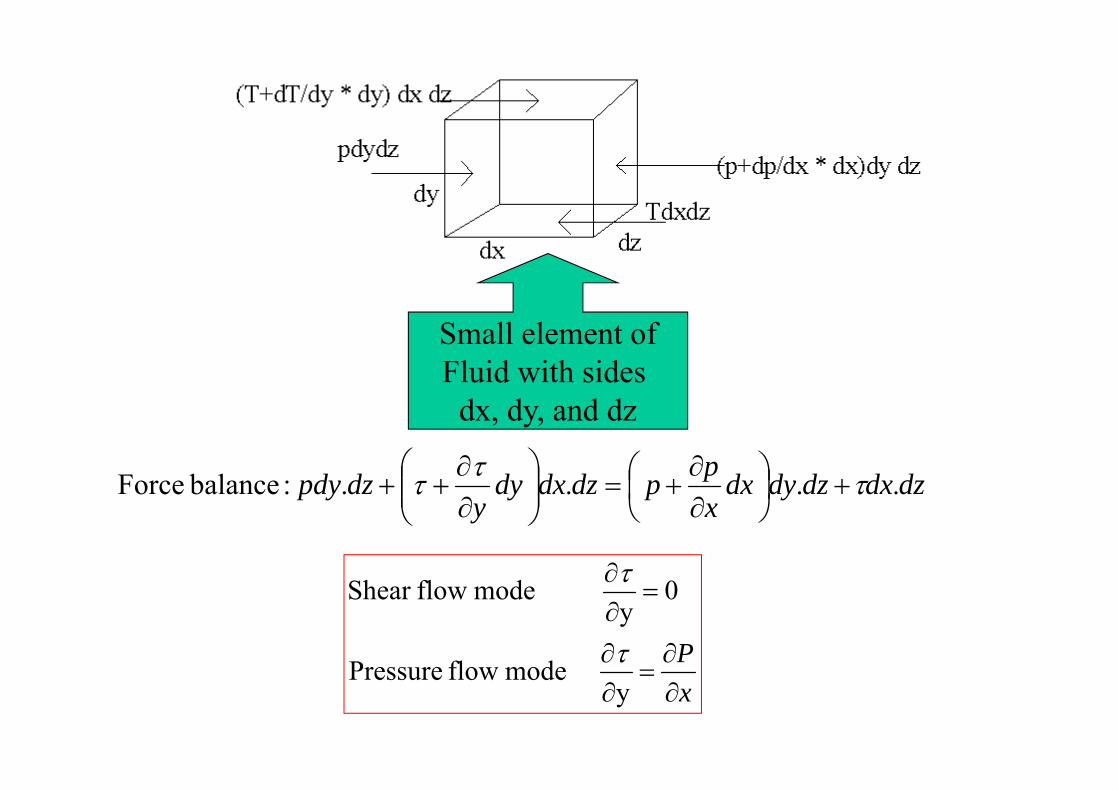
dzdxdzdydxxppdzdxdy
ydzpdy .... :balance Force τττ +⎟
⎠⎞
⎜⎝⎛
∂∂
+=⎟⎟⎠
⎞⎜⎜⎝
⎛∂∂
++
Small element ofFluid with sides
dx, dy, and dz
xP∂∂
=∂∂
=∂∂
y mode flow Pressure
0y
mode flowShear
τ
τ
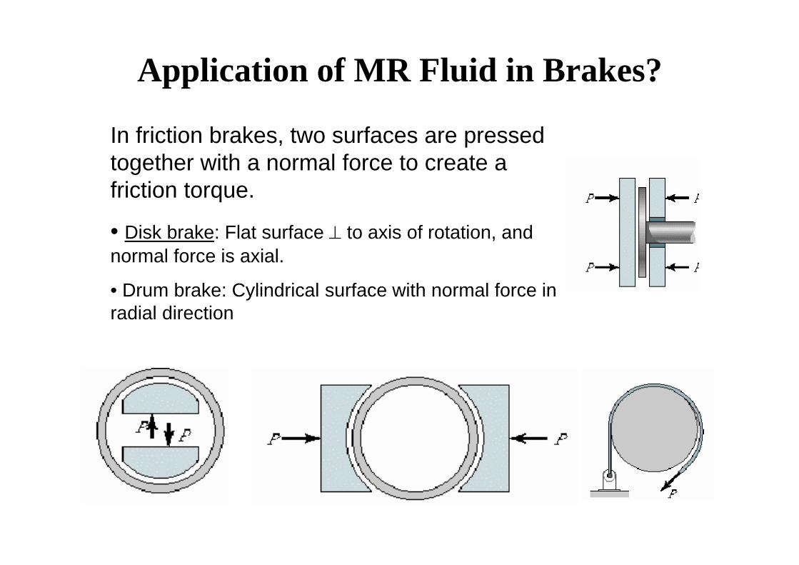
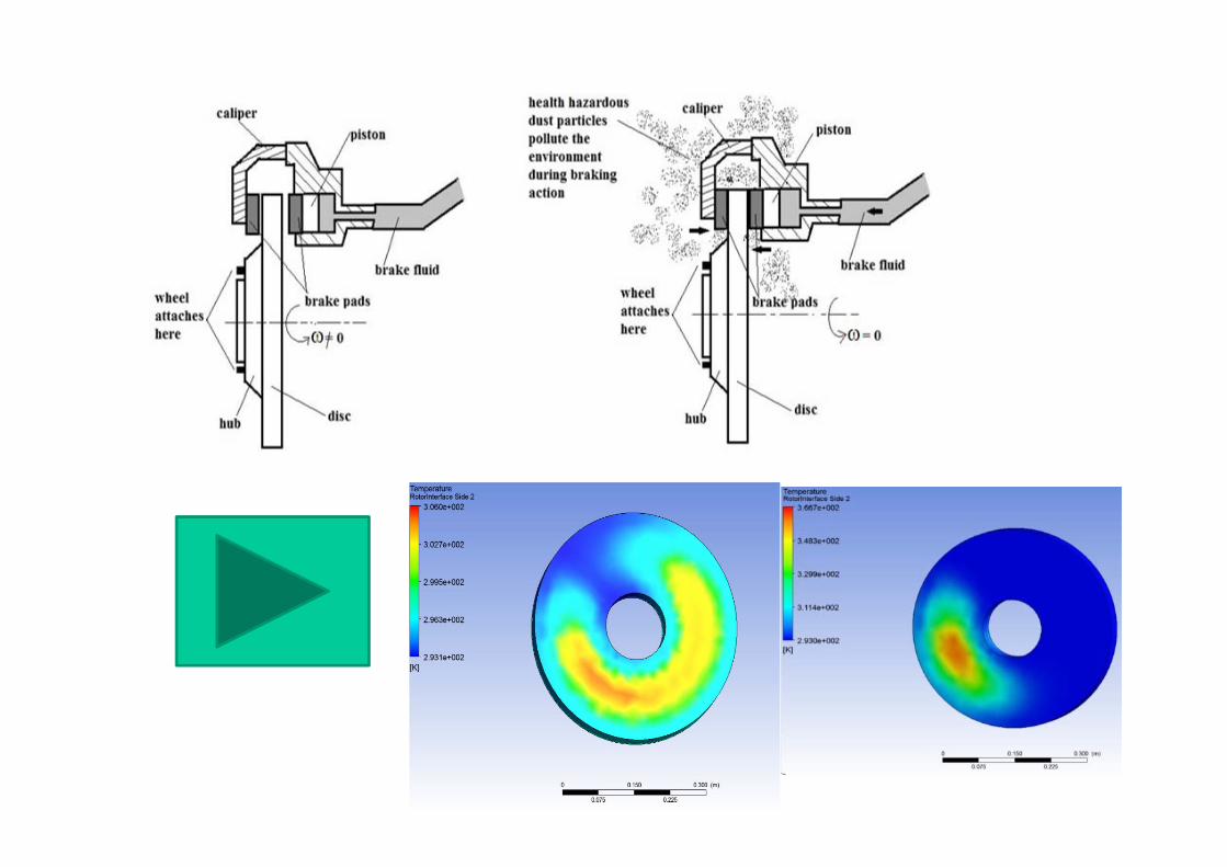
In friction brakes, two surfaces are pressed together with a normal force to create a friction torque.
• Disk brake: Flat surface ⊥ to axis of rotation, and normal force is axial.
• Drum brake: Cylindrical surface with normal force in radial direction
Application of MR Fluid in Brakes?
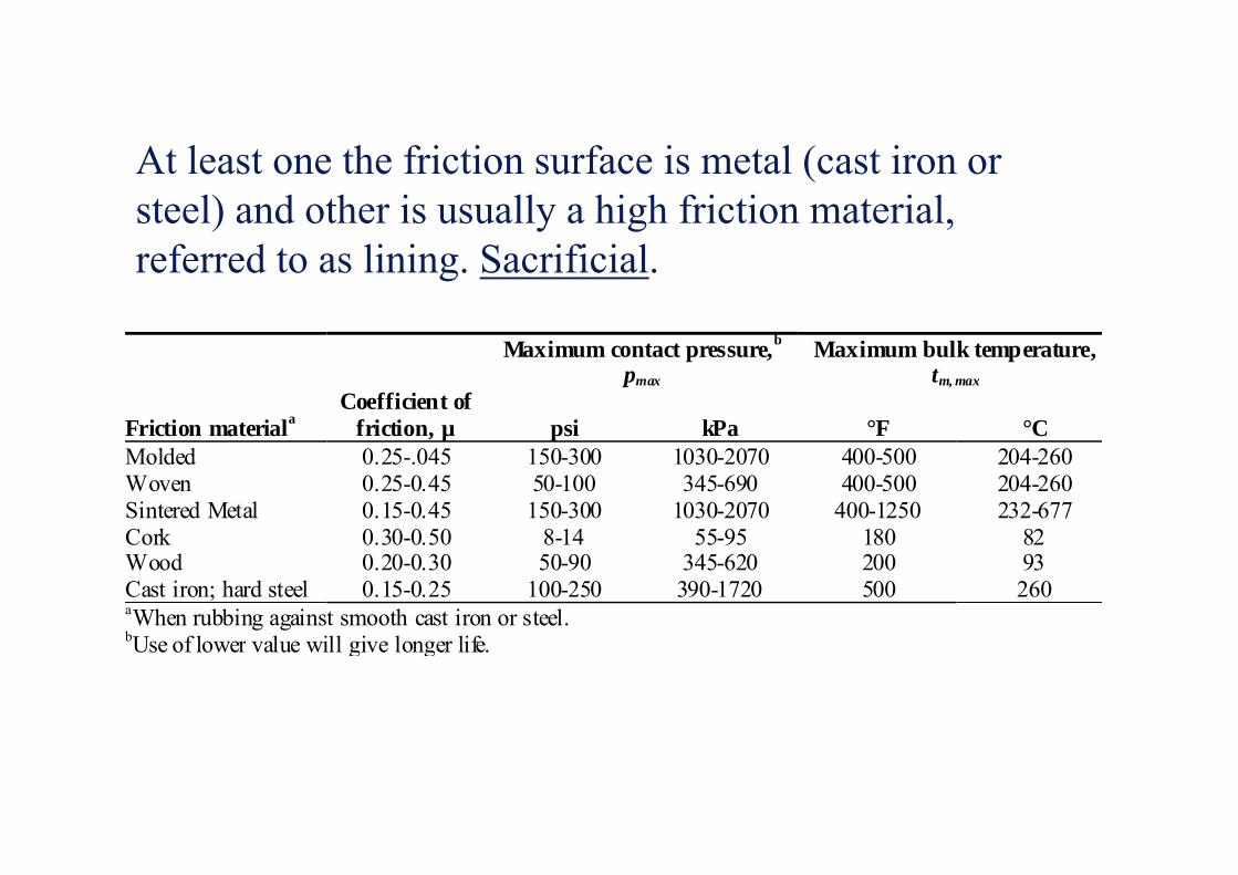
Maximum contact pressure,b
pmax
Maximum bulk temperature,tm, max
Friction materialaCoefficient of
friction, µ psi kPa °F °CMoldedWovenSintered MetalCorkWoodCast iron; hard steel
0.25-.0450.25-0.450.15-0.450.30-0.500.20-0.300.15-0.25
150-30050-100150-300
8-1450-90
100-250
1030-2070345-690
1030-207055-95
345-620390-1720
400-500400-500
400-1250180200500
204-260204-260232-677
8293260
aWhen rubbing against smooth cast iron or steel.bUse of lower value will give longer life.
At least one the friction surface is metal (cast iron or steel) and other is usually a high friction material, referred to as lining. Sacrificial.
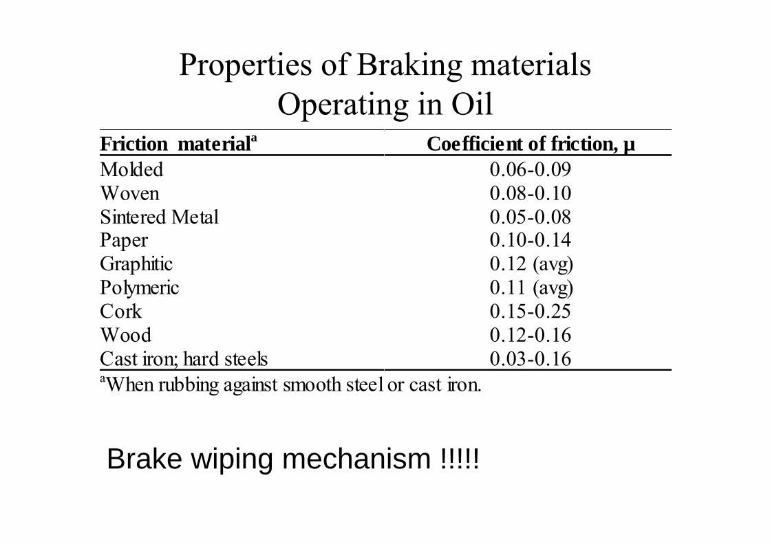
Properties of Braking materials Operating in Oil
Friction materiala Coefficient of friction, µMoldedWovenSintered MetalPaperGraphiticPolymericCorkWoodCast iron; hard steels
0.06-0.090.08-0.100.05-0.080.10-0.140.12 (avg)0.11 (avg)0.15-0.250.12-0.160.03-0.16
aWhen rubbing against smooth steel or cast iron.
Brake wiping mechanism !!!!!
3/14/2014 27
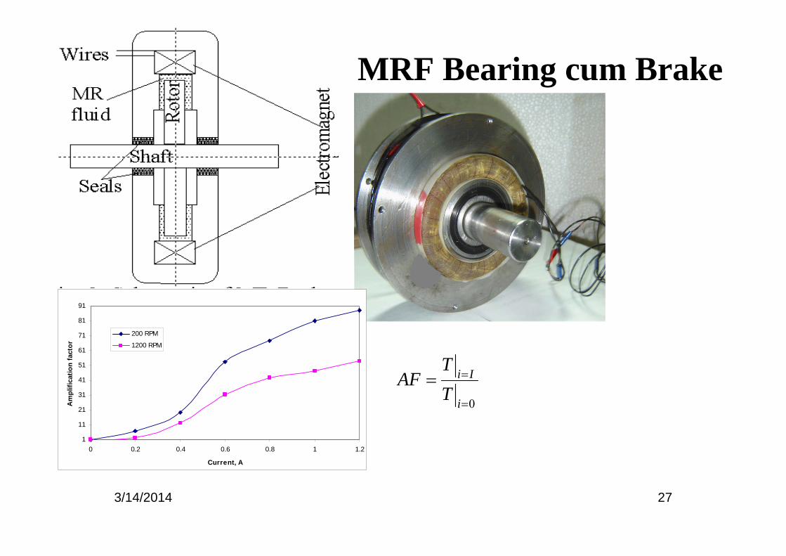
MRF Bearing cum Brake
1
11
21
31
41
51
61
71
81
91
0 0.2 0.4 0.6 0.8 1 1.2
Current, A
Am
plifi
catio
n fa
ctor
200 RPM
1200 RPM
0=
==i
Ii
TT
AF
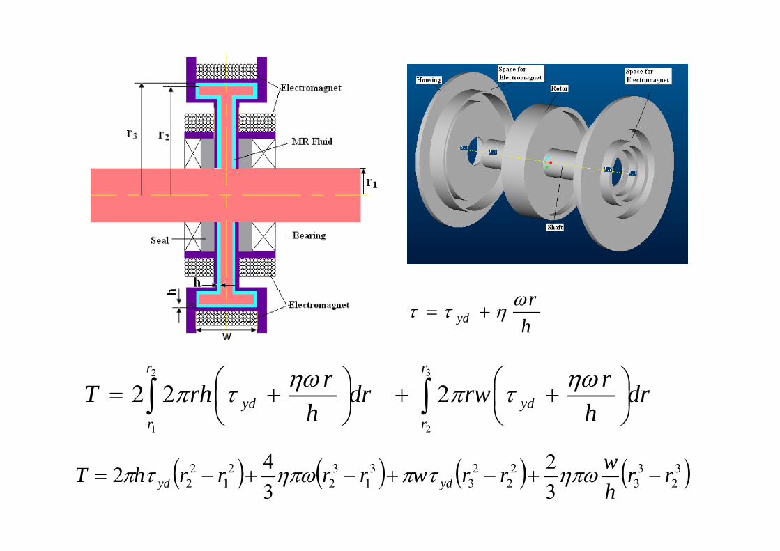
hr
ydωηττ +=
drh
rrwdrh
rrhTr
ryd
r
ryd ∫∫ ⎟
⎠⎞
⎜⎝⎛ ++⎟
⎠⎞
⎜⎝⎛ +=
3
2
2
1
222 ηωτπηωτπ
( ) ( ) ( ) ( )32
33
22
23
31
32
21
22 3
2342 rr
hwrrwrrrrhT ydyd −+−+−+−= ηπωτπηπωτπ
3/14/2014 29
MR BrakeTitle: Magnetorheological brake operating under shear, squeezing and valve mode.
Inventor: H. Hirani and C. Sarkar
Application number: 2530/Del/2013

Application of MR Fluid in Dampers?
• The practical necessities often require attenuation of the vibrations.– Passive Damper– Active Damper– Semi-active Damper
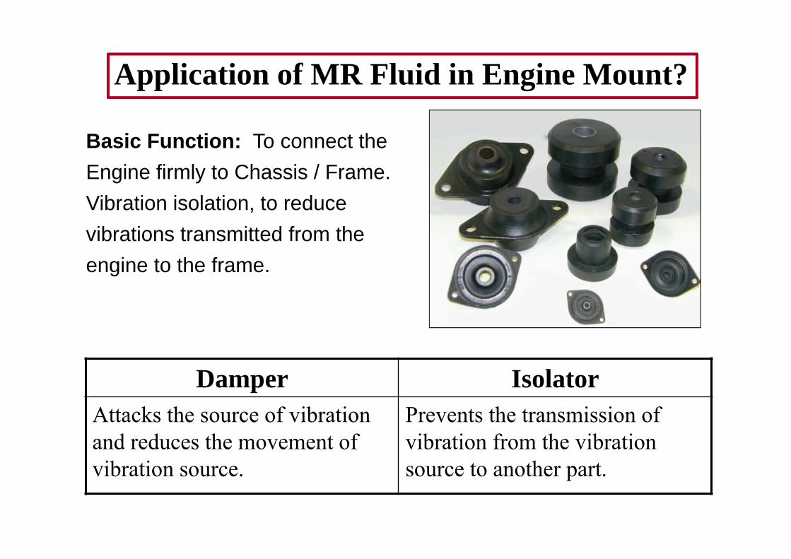
Application of MR Fluid in Engine Mount?
Basic Function: To connect the Engine firmly to Chassis / Frame. Vibration isolation, to reduce vibrations transmitted from the engine to the frame.
Damper IsolatorAttacks the source of vibration and reduces the movement of vibration source.
Prevents the transmission of vibration from the vibration source to another part.

Mount Advantages Disadvantages
Passive Easy to design, availability, shows better performance at tuned frequency
Can’t change response as per change in input frequency.
Active:Electromechanical actuators, piezoelectric elements along with closed loop feed back system.
Ability to adapt to varying operating conditionsOptimizing the mount effectiveness under all conditions.
Costs.Failure of any component brings system to stand still condition.
Semi-active: combination of the active and passive isolator
Even though the actuation or feed back system fails it functions as a passive mount serving the purpose.
Cost higher than the passive type of mount.
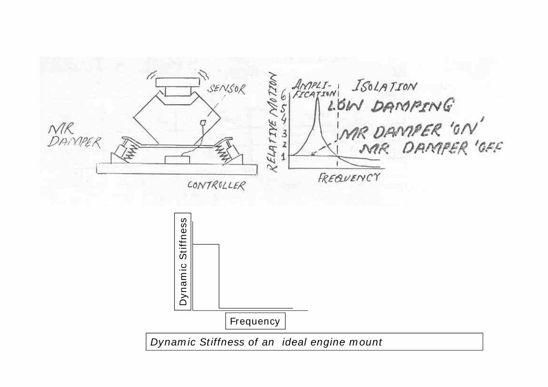
Frequency
Dyn
amic
Stif
fnes
s
Dynamic Stiffness of an ideal engine mount
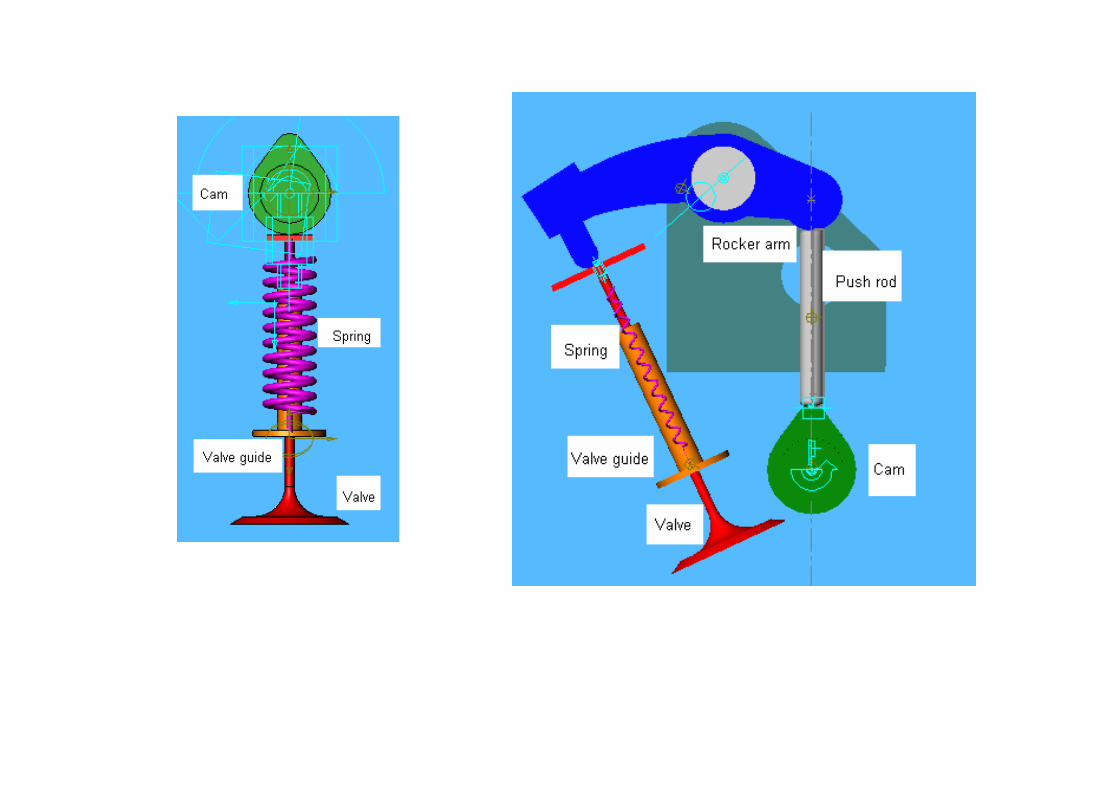
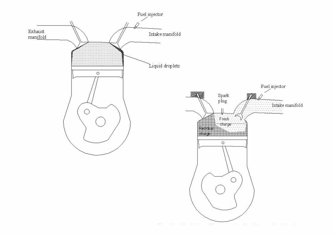
Application of MR Fluid in Engine Valves• Ex: In most of engines, the valve timings and lift are
optimized for one set of operating conditions. – engine operates in various load and speed
conditions. Consequently, to optimize the engine performance in any condition and any circumstance, a need exists for a device that permits variable valve actuation.
– Variable lift/timing (VVA) to exploit benefits:• Fuel economy• Elimination of throttling • Reduction in emission.
Reference: SAE 1999-01-0329, SAE 2003-01-0029, SAE 2003-01-0036, SAE 2003-01-0052, SAE 2004-01-1386, ..
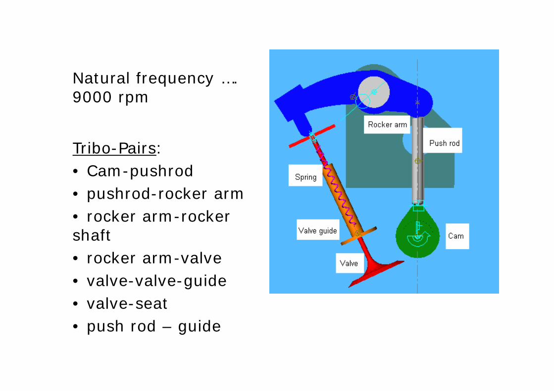
Natural frequency …. 9000 rpm
Tribo-Pairs: • Cam-pushrod• pushrod-rocker arm• rocker arm-rocker shaft• rocker arm-valve • valve-valve-guide • valve-seat• push rod – guide
3/14/2014 Total slides = 27 38
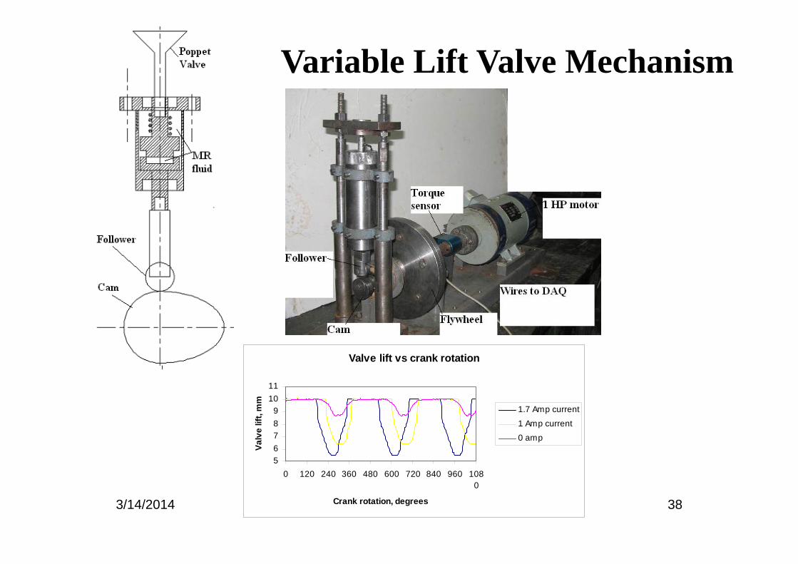
Variable Lift Valve Mechanism
Valve lift vs crank rotation
56789
1011
0 120 240 360 480 600 720 840 960 1080
Crank rotation, degrees
Valv
e lif
t, m
m
1.7 Amp current
1 Amp current
0 amp
3/14/2014 39
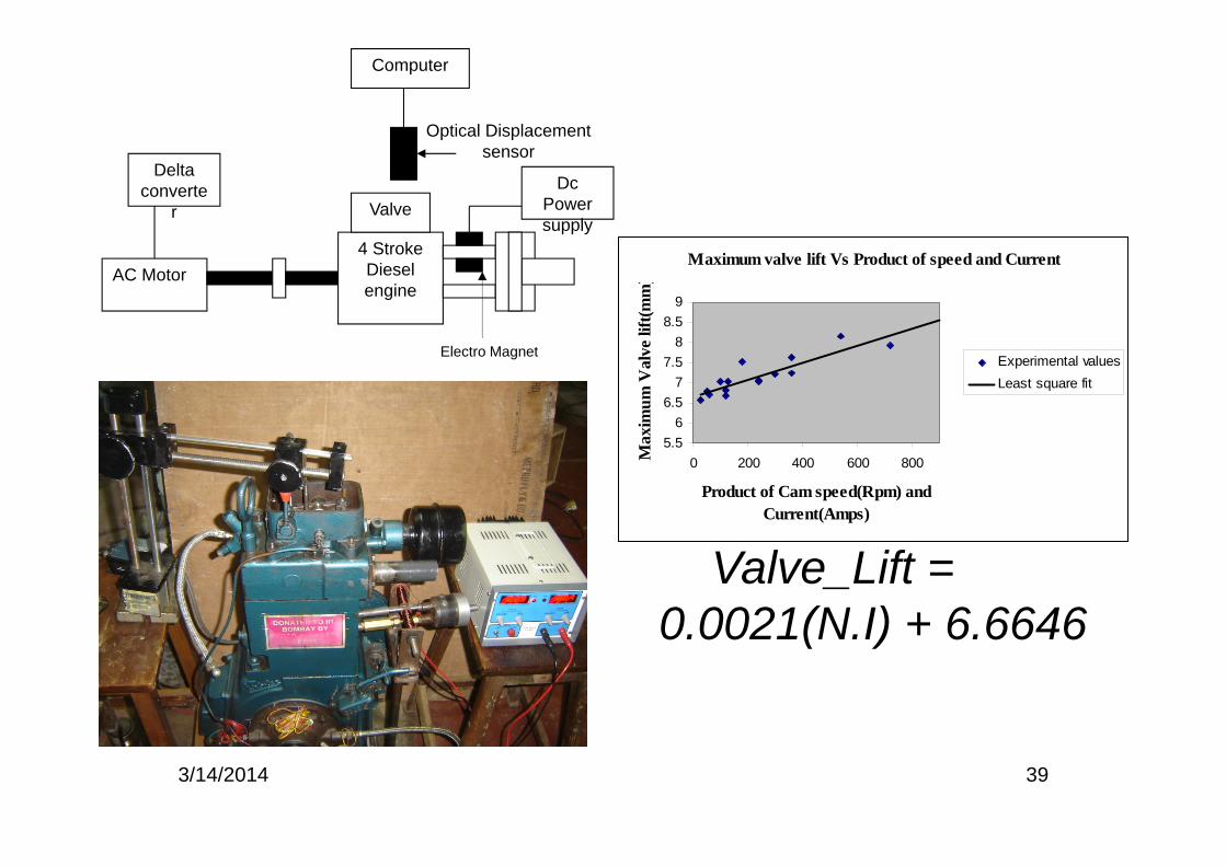
Delta converte
r
AC Motor4 Stroke Diesel engine
ValveDc
Power supply
Electro Magnet
Optical Displacement sensor
Computer
Maximum valve lift Vs Product of speed and Current
5.56
6.57
7.58
8.59
0 200 400 600 800
Product of Cam speed(Rpm) and Current(Amps)
Max
imum
Val
ve li
ft(m
m)
Experimental valuesLeast square fit
Valve_Lift = 0.0021(N.I) + 6.6646
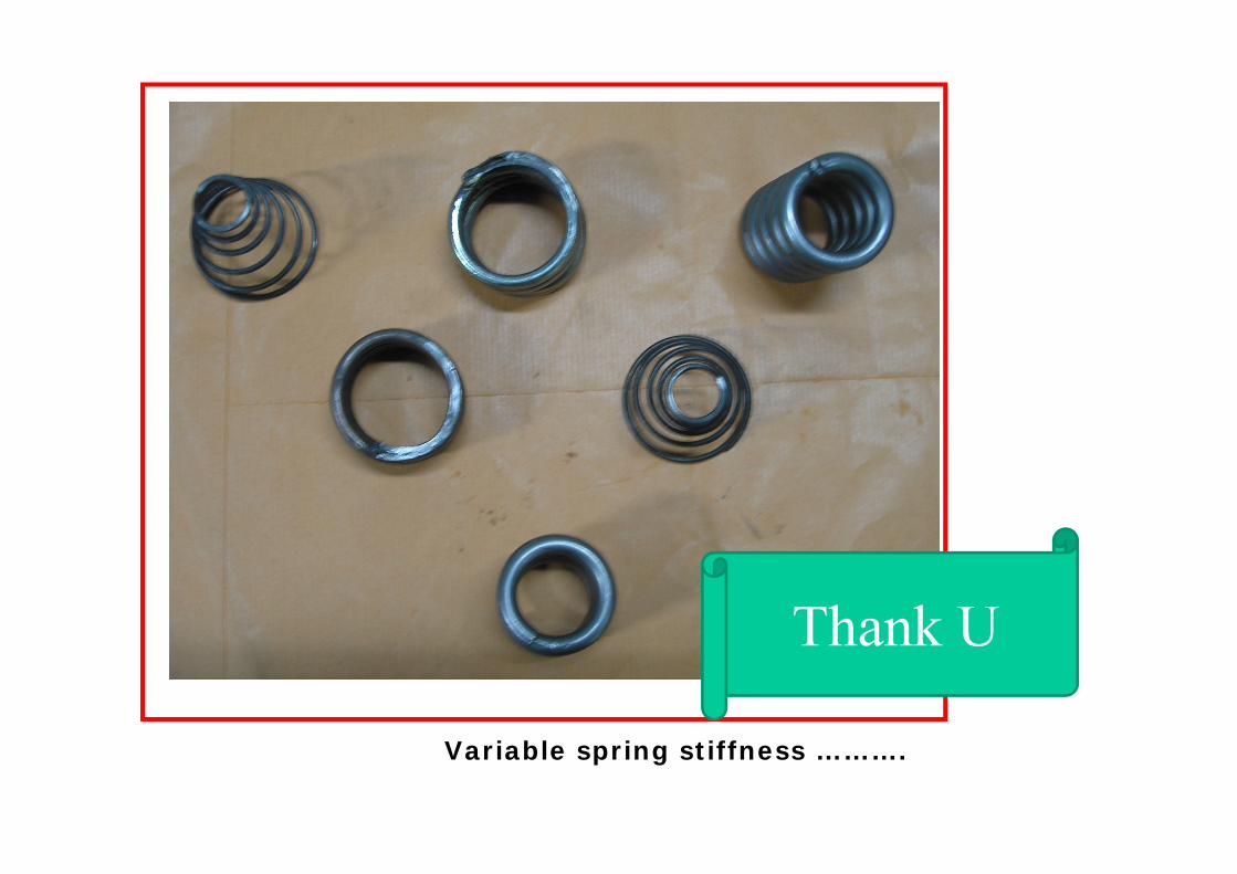
Variable spring stiffness ……….
Thank U