Magneto-induced rheological properties of ...
14
Magneto-induced rheological properties of magnetorheological gel under quasi-static shear with large deformation Runsong Mao, Huixing Wang, Guang Zhang, Xudan Ye and Jiong Wang * Magnetorheological gel (MRG) is a kind of magneto-sensitive smart material mainly composed of soft magnetic particles and polyurethane, which can decrease or even avoid the severe sedimentation problem appearing in MR fluids. In this work, the rheological properties of MRG under quasi-statically monotonic and cyclic loading with large deformation were investigated, respectively. The results could provide effective guidance for the design of MR devices that are often subjected to quasi-static loading. Firstly, MRG was fabricated by mixing carbonyl iron particles (CIPs) with the polyurethane matrix. Then, variations of normal force with time and magnetic field for MRG were tested and discussed. Moreover, the influences of CIPs content, shear rate, shear strain amplitude and magnetic field on the energy dissipation density of MRG were analyzed. The results showed the magneto-induced damping performance of MRG is highly relevant to the CIPs content and magnetic field, i.e. the magneto-induced enhancement of energy dissipation density of MRG with 60% CIPs content could reach up to 104 900% when the external magnetic strength increases to 391 kA m 1 . Furthermore, the related mechanisms, from the perspective of microstructure, were proposed to qualitatively explain the various mechanical phenomena occurring in shear stress and normal force. 1. Introduction Magnetorheological (MR) materials are a novel type of intelli- gent material whose rheological properties can be controlled rapidly and reversibly by adjusting the external magnetic eld. 1,2 To date, liquid-like MR uid 3,4 (MRF) and solid-like MR elas- tomer 5,6 (MRE) are the two most famous MR materials and have been widely investigated in devices such as dampers and isolators, etc. However, there are few reports on the commer- cialization of MR applications based on MRF or MRE. The reason for this is that, for MR uids, the so magnetic particles dispersed in the liquid matrix (mineral oil or water, etc.) are easy to settle due to the huge density difference between them. 7,8 This defect will give rise to some severe problems such as reduction of the stability and lifetime of the devices. On the other hand, the solid matrix based MRE could thoroughly avoid the sedimentation problem. However, MRE has comparatively low MR effect 9,10 because the movement of particles is restricted by the rigid matrix (natural or synthetic rubber, etc.). Different from MRF and MRE, MR gel possesses excellent sedimentation stability and a relatively high MR effect due to the existence of the polymer matrix, which has attracted many researchers' attention in recent years. 11–13 Moreover, MRG also has many other prominent features, 14–16 such as electric property, acoustic property, which are not possessed by MRF and MRE. Overall, the occurrence of MRG may realize the commercialization of MR materials in the practical devices, such as MR dampers, 17–19 magnetic-controlled sensor and actuators. 20 The rheological properties, e.g. viscosity, yield stress, are important factors in the design of the MR devices. Until now, researchers conducted a series of experiments on the rheolog- ical properties of MRG. Xu et al. 21 investigated the time- dependent stress relaxation behavior of MRG under different magnetic elds. It found that the instantaneous and stable modulus of MRG with ordered chain-like microstructures are larger than those of MRG with unordered microstructures in the absence of a magnetic eld. 21 Zhang et al. 22 carried out the static and dynamic shear tests to study the rheological properties of polyurethane-based MRG. The static experiments indicated that, compared with other factors, the magnetic eld has a stronger inuence on the rheological properties. Also, the tendency with magnetic strength can be divided into initial increment, the linear increment and the saturate tendency. The dynamic oscillation tests show the maximum loss modulus of the MRG with 80% CIPs content could reach 0.626 MPa and the corresponding strain amplitude was 0.526%. As known, the exterior loading applied to MR materials are basically catego- rized into three kinds: static loading, dynamic loading and quasi-static loading. 23–25 However, the current experiments on the rheological properties of MRG are almost conducted under the static and dynamic shear. To the best of our knowledge, the School of Mechanical Engineering, Nanjing University of Science and Technology, Nanjing 210094, China. E-mail: [email protected] Cite this: RSC Adv. , 2020, 10, 31691 Received 4th July 2020 Accepted 20th August 2020 DOI: 10.1039/d0ra05843b rsc.li/rsc-advances This journal is © The Royal Society of Chemistry 2020 RSC Adv. , 2020, 10, 31691–31704 | 31691 RSC Advances PAPER Open Access Article. Published on 27 August 2020. Downloaded on 2/14/2022 2:41:47 PM. This article is licensed under a Creative Commons Attribution-NonCommercial 3.0 Unported Licence. View Article Online View Journal | View Issue
Transcript of Magneto-induced rheological properties of ...
RSC Advances
PAPER
Ope
n A
cces
s A
rtic
le. P
ublis
hed
on 2
7 A
ugus
t 202
0. D
ownl
oade
d on
2/1
4/20
22 2
:41:
47 P
M.
Thi
s ar
ticle
is li
cens
ed u
nder
a C
reat
ive
Com
mon
s A
ttrib
utio
n-N
onC
omm
erci
al 3
.0 U
npor
ted
Lic
ence
.
View Article OnlineView Journal | View Issue
Magneto-induce
School of Mechanical Engineering, Nanjin
Nanjing 210094, China. E-mail: wjiongz@n
Cite this: RSC Adv., 2020, 10, 31691
Received 4th July 2020Accepted 20th August 2020
DOI: 10.1039/d0ra05843b
rsc.li/rsc-advances
This journal is © The Royal Society o
d rheological properties ofmagnetorheological gel under quasi-static shearwith large deformation
Runsong Mao, Huixing Wang, Guang Zhang, Xudan Ye and Jiong Wang*
Magnetorheological gel (MRG) is a kind of magneto-sensitive smart material mainly composed of soft
magnetic particles and polyurethane, which can decrease or even avoid the severe sedimentation
problem appearing in MR fluids. In this work, the rheological properties of MRG under quasi-statically
monotonic and cyclic loading with large deformation were investigated, respectively. The results could
provide effective guidance for the design of MR devices that are often subjected to quasi-static loading.
Firstly, MRG was fabricated by mixing carbonyl iron particles (CIPs) with the polyurethane matrix. Then,
variations of normal force with time and magnetic field for MRG were tested and discussed. Moreover,
the influences of CIPs content, shear rate, shear strain amplitude and magnetic field on the energy
dissipation density of MRG were analyzed. The results showed the magneto-induced damping
performance of MRG is highly relevant to the CIPs content and magnetic field, i.e. the magneto-induced
enhancement of energy dissipation density of MRG with 60% CIPs content could reach up to 104 900%
when the external magnetic strength increases to 391 kA m�1. Furthermore, the related mechanisms,
from the perspective of microstructure, were proposed to qualitatively explain the various mechanical
phenomena occurring in shear stress and normal force.
1. Introduction
Magnetorheological (MR) materials are a novel type of intelli-gent material whose rheological properties can be controlledrapidly and reversibly by adjusting the external magnetic eld.1,2
To date, liquid-like MR uid3,4 (MRF) and solid-like MR elas-tomer5,6 (MRE) are the two most famous MR materials and havebeen widely investigated in devices such as dampers andisolators, etc. However, there are few reports on the commer-cialization of MR applications based on MRF or MRE. Thereason for this is that, for MR uids, the somagnetic particlesdispersed in the liquidmatrix (mineral oil or water, etc.) are easyto settle due to the huge density difference between them.7,8
This defect will give rise to some severe problems such asreduction of the stability and lifetime of the devices. On theother hand, the solid matrix based MRE could thoroughly avoidthe sedimentation problem. However, MRE has comparativelylow MR effect9,10 because the movement of particles is restrictedby the rigid matrix (natural or synthetic rubber, etc.). Differentfrom MRF and MRE, MR gel possesses excellent sedimentationstability and a relatively high MR effect due to the existence ofthe polymer matrix, which has attracted many researchers'attention in recent years.11–13 Moreover, MRG also has manyother prominent features,14–16 such as electric property, acoustic
g University of Science and Technology,
just.edu.cn
f Chemistry 2020
property, which are not possessed by MRF and MRE. Overall,the occurrence of MRG may realize the commercialization ofMR materials in the practical devices, such as MR dampers,17–19
magnetic-controlled sensor and actuators.20
The rheological properties, e.g. viscosity, yield stress, areimportant factors in the design of the MR devices. Until now,researchers conducted a series of experiments on the rheolog-ical properties of MRG. Xu et al.21 investigated the time-dependent stress relaxation behavior of MRG under differentmagnetic elds. It found that the instantaneous and stablemodulus of MRG with ordered chain-like microstructures arelarger than those of MRGwith unorderedmicrostructures in theabsence of a magnetic eld.21 Zhang et al.22 carried out the staticand dynamic shear tests to study the rheological properties ofpolyurethane-based MRG. The static experiments indicatedthat, compared with other factors, the magnetic eld hasa stronger inuence on the rheological properties. Also, thetendency with magnetic strength can be divided into initialincrement, the linear increment and the saturate tendency. Thedynamic oscillation tests show the maximum loss modulus ofthe MRG with 80% CIPs content could reach 0.626 MPa and thecorresponding strain amplitude was 0.526%. As known, theexterior loading applied to MR materials are basically catego-rized into three kinds: static loading, dynamic loading andquasi-static loading.23–25 However, the current experiments onthe rheological properties of MRG are almost conducted underthe static and dynamic shear. To the best of our knowledge, the
RSC Adv., 2020, 10, 31691–31704 | 31691

Table 1 Raw material used to prepare the magnetorheological gel (MRG)
Raw materials Usage Producer
Toluene diisocyanate (TDI) Main reactant Tokyo Chemical Industry Co., Ltd, JapanPolypropylene glycol (PPG-2000) Main reactant Sigma-Aldrich (Shanghai) Trading Co., Ltd, ChinaDipropylene glycol (SOL) Chain extender Sigma-Aldrich (Shanghai) Trading Co., Ltd, ChinaStannous octoate Catalyst Sinopharm Chemical Reagent Co., Ltd, ChinaCarbonyl iron powder (CIP) Magnetic particle BASF, Germany
RSC Advances Paper
Ope
n A
cces
s A
rtic
le. P
ublis
hed
on 2
7 A
ugus
t 202
0. D
ownl
oade
d on
2/1
4/20
22 2
:41:
47 P
M.
Thi
s ar
ticle
is li
cens
ed u
nder
a C
reat
ive
Com
mon
s A
ttrib
utio
n-N
onC
omm
erci
al 3
.0 U
npor
ted
Lic
ence
.View Article Online
investigation on the rheological properties of MRG under quasi-static shear has never been reported. For PU-based MR gels, inthe absence of a magnetic eld, the movement of so segmentsin the polymer matrix is the primary contribution to the rheo-logical performance compared with that of the magnetic parti-cles. However, in the presence of a magnetic eld, the magneto-induced rheological properties under quasi-static shear arehighly relevant to the coupling effects between the particlechains and the polymeric matrix. Particle chains were contin-uously recovered while being destroyed by shearing under thecontinuous application of a magnetic eld and quasi-staticshear with a small shear rate. Simultaneously, the polymermatrix is also continually recovering due to the thixotropicproperties of the matrix. At this time, the continuously recov-ered particle chains and polymer matrix are further coupledwith each other, resulting in a more complex microstructure.These phenomena inevitably lead to different rheologicalproperties.26,27 Therefore, it is urgent to investigate themagneto-mechanical performance of MRG under quasi-static shear withand without magnetic eld.
The purpose of this study is to investigate the magneto-induced rheological properties of MRG with different CIPscontent under quasi-statically loading and large shear defor-mation. Firstly, MRG with 40%, 60%, and 70% CIPs content
Fig. 1 Process of the preparation of the MRG.
31692 | RSC Adv., 2020, 10, 31691–31704
were prepared, respectively. Then, the magnetic eld-dependent deformation of MRG was tested and the corre-sponding magneto-induced normal force of sample is analyzed.Finally, the magneto-induced rheological properties anddamping performance of MRG under monotonic and cyclicshearing code with different shear rates, CIPs content, strainamplitudes and magnetic elds are discussed.
2. Experimental2.1 Raw materials
Table 1 presents the details of the raw materials used for thepreparation of MRG. Toluene diisocyanate (TDI; 2,4- z 80%,2,6- z 20%, Tokyo Chemical Industry Co., Ltd, Japan) andpolypropylene glycol (PPG-2000, Mn ¼ 2000, Sigma-Aldrich(Shanghai) Trading Co., Ltd, China) were selected as the twomain reactants to fabricate the PU matrix. Dipropylene glycol(SOL, Sigma-Aldrich (Shanghai) Trading Co., Ltd, China) wasselected as the chain extender. Stannous octoate (SinopharmChemical Reagent Co., Ltd, China) was selected as a catalyst.Carbonyl iron powder (CIPs, type CN, BASF, Germany with anaverage particle size of about 6 mm) was selected as the somagnetic particles.
This journal is © The Royal Society of Chemistry 2020

Fig. 2 Photograph of MRG: the sample (a); the microstructure (b).
Table 2 Compositions of the PU-based magnetorheological gel(MRG)
Samples CIP (wt%) PU (wt%)
MRG-40 40 60MRG-60 60 40MRG-70 70 30
Paper RSC Advances
Ope
n A
cces
s A
rtic
le. P
ublis
hed
on 2
7 A
ugus
t 202
0. D
ownl
oade
d on
2/1
4/20
22 2
:41:
47 P
M.
Thi
s ar
ticle
is li
cens
ed u
nder
a C
reat
ive
Com
mon
s A
ttrib
utio
n-N
onC
omm
erci
al 3
.0 U
npor
ted
Lic
ence
.View Article Online
The weight ratio of TDI to PPG was decided by the followingformula:
nNCO
nOH
¼ mTDI=174:15 g mol�1
mPPG=2000 g mol�1
where, the nNCO represents the mol of –NCO group, nOH repre-sents the mol of –OH group,mTDI andmPPG represent the weight
of TDI and PPG, respectively. In this study,nNCOnOH
was selected as
3 : 1 according to the paper of Wei28 and Zhang.29 Meanwhile,the weight of SOL was decided by the following formula:
mSOL ¼ 134:17 g mol�1
��
mTDI
174:15 g mol�1 � 1:1� mPPG
2000 g mol�1
�
where, the mSOL represents the weight of SOL.
Fig. 3 Schematic diagram of MCR 302 rheometer used for the test.
This journal is © The Royal Society of Chemistry 2020
2.2 Fabrication of MRG
There are three steps in the fabrication of the PU matrix (asshown in Fig. 1). Firstly, PPG was evaporated at 100 �C in the lodrier for about one hour. Then, TDI and PPG were agitated ina 250 mL three-necked round bottom ask with a mechanicalstirrer and the reaction was kept at 80 �C. Two hours later, SOLwas added into the ask and the temperature of the reactionwas simultaneously dropped to 60 �C. Finally, moderate stan-nous octoate was added into the ask at the same temperature.The stirrer agitated at high speed during the whole reaction.
Aer the fabrication of the PU matrix, the CIPs was addedinto it immediately before the matrix chilled down. Moreover,stirring vigorously for a long enough time to make sure the ironparticles and matrix mixed adequately. Then, the geometry ofthe self-developed MRG is presented in Fig. 2. The microstruc-ture of MRG is observed with a digital microscope (type VHX-100, Keyence) and the shining white points shown in Fig. 2(b)represents magnetic particles. In this paper, three kinds of MRGwith different CIPs weight percentages were synthesized and thesamples were named as MRG-40, MRG-60, MRG-70 individually(Table 2).
2.3 Experimental and test
A commercial rheometer (Type MCR 302, Anton Paar Co., Graz,Austria) equipped with the magnetorheological module (Type
RSC Adv., 2020, 10, 31691–31704 | 31693

Fig. 4 Schematic diagram of quasi-static shear mode: monotonic shear mode (a) and cyclic shear mode (b).
Fig. 5 The large deformation of MRGwith and without magnetic field.MRG presents a semi-solid state under 0 kA m�1 magnetic field (a).After applying a uniform 740 kA m�1 magnetic field, MRG performsneedle-like macroscopic behavior (b). After removing the externalmagnetic field, MRG returns to its original state gradually (c).
RSC Advances Paper
Ope
n A
cces
s A
rtic
le. P
ublis
hed
on 2
7 A
ugus
t 202
0. D
ownl
oade
d on
2/1
4/20
22 2
:41:
47 P
M.
Thi
s ar
ticle
is li
cens
ed u
nder
a C
reat
ive
Com
mon
s A
ttrib
utio
n-N
onC
omm
erci
al 3
.0 U
npor
ted
Lic
ence
.View Article Online
MRD180, Anton Paar Co., Austria) was used to conduct a seriesof experiments to study the rheological properties of MRGunder monotonic and cyclic loading. The schematic diagram ofMCR 302 is shown in Fig. 3. During the process of the experi-ment, MRG was laid between the magnetic generator androtating head. The bottom plate of the rotating head hasa diameter of 20 mm and the gap distance between the twoplates was set as 1 mm. A magnetic cover is employed tointensify the magnetic eld and make it identical in thedistance where MRG is placed. The shear stress and normalforce of MRG were rstly measured with the strain-controlledmode and then the data was recorded and processed with
Fig. 6 The normal force of Fn of MRG in the condition where themagnetic field changes linearly from 0 kA m�1 to 740 kA m�1 (i.e. from0 A to 4 A).
31694 | RSC Adv., 2020, 10, 31691–31704
a data acquisition board (DAQ) and computer. The directionalong the direction of magnetic eld (i.e. vertical to bottomplate) is dened as the normal direction.
As shown in Fig. 4, the quasi-static shear test is conductedunder two different mode,30 i.e. monotonic shear mode andcyclic shear mode. The test fundamental of monotonic shearmode is presented in Fig. 4(a). The shear strain grows linearlyfrom 0% to 100% in four different times (i.e. 200 s, 50 s, 25 s and12 s). Thus, the corresponding shear rates are 0.005 s�1, 0.02s�1, 0.04 s�1 and 0.083 s�1, respectively. Fig. 4(b) presents thetest fundamental of cyclic shear mode. The shear strain thatapplied on MRG varies in a triangular wave, and the shear timeand corresponding shear rates are the same as those undermonotonic shear mode. Furthermore, all the experiments werecarried out at a temperature of 25 �C.
3. Results and discussion3.1 Magneto-induced normal force of MRG under largedeformation
To investigate the quasi-static properties of MRG under largedeformation, MRG-70 was chosen as an experimental sampleand placed directly between the two plates of rheometer, asshown in Fig. 5(a). Then, a uniform 740 kA m�1 magneticstrength was applied to the sample and lasted 60 seconds. Anobvious change can be found from Fig. 5(a) to Fig. 5(b). Flower-like structures are observed in Fig. 5(b), and feel rigid when wetouched them. The ower-like structures started to ‘fade’, andfelt soer than the former state when the magnetic eld returnsto 0. This phenomenon authenticates the fact that the unor-dered particle microstructures in the absence of a magneticeld will change into powerful chain-like or column-likemicrostructures in the presence of a magnetic eld. Moreover,when the external magnetic eld is removed, the needle-likeshape (Fig. 5(c)) retained for a while and did not return to theoriginal state (Fig. 5(a)) immediately, which has not been re-ported in MR uid and elastomer.
Fig. 6 displayed the variations of normal force Fn withmagnetic eld for MRG with different CIPs content. Themagnetic strength increases linearly from 0 kA m�1 to 740 kAm�1 during the experiments. The normal force increases rapidlyrst and then slowly with the magnetic strength. Besides, MRG
This journal is © The Royal Society of Chemistry 2020
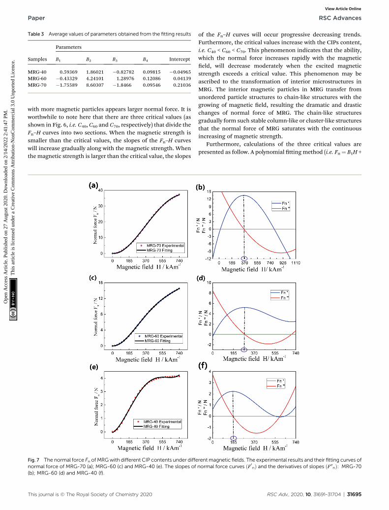
Table 3 Average values of parameters obtained from the fitting results
Samples
Parameters
B1 B2 B3 B4 Intercept
MRG-40 0.59369 1.86021 �0.82782 0.09815 �0.04965MRG-60 �0.43329 4.24101 1.28976 0.12086 0.04139MRG-70 �1.75589 8.60307 �1.8466 0.09546 0.21036
Paper RSC Advances
Ope
n A
cces
s A
rtic
le. P
ublis
hed
on 2
7 A
ugus
t 202
0. D
ownl
oade
d on
2/1
4/20
22 2
:41:
47 P
M.
Thi
s ar
ticle
is li
cens
ed u
nder
a C
reat
ive
Com
mon
s A
ttrib
utio
n-N
onC
omm
erci
al 3
.0 U
npor
ted
Lic
ence
.View Article Online
with more magnetic particles appears larger normal force. It isworthwhile to note here that there are three critical values (asshown in Fig. 6, i.e. C40, C60 and C70, respectively) that divide theFn–H curves into two sections. When the magnetic strength issmaller than the critical values, the slopes of the Fn–H curveswill increase gradually along with the magnetic strength. Whenthemagnetic strength is larger than the critical value, the slopes
Fig. 7 The normal force Fn of MRGwith different CIP contents under diffenormal force of MRG-70 (a); MRG-60 (c) and MRG-40 (e). The slopes of(b); MRG-60 (d) and MRG-40 (f).
This journal is © The Royal Society of Chemistry 2020
of the Fn–H curves will occur progressive decreasing trends.Furthermore, the critical values increase with the CIPs content,i.e. C40 < C60 < C70. This phenomenon indicates that the ability,which the normal force increases rapidly with the magneticeld, will decrease moderately when the excited magneticstrength exceeds a critical value. This phenomenon may beascribed to the transformation of interior microstructures inMRG. The interior magnetic particles in MRG transfer fromunordered particle structures to chain-like structures with thegrowing of magnetic eld, resulting the dramatic and drasticchanges of normal force of MRG. The chain-like structuresgradually form such stable column-like or cluster-like structuresthat the normal force of MRG saturates with the continuousincreasing of magnetic strength.
Furthermore, calculations of the three critical values arepresented as follow. A polynomial tting method (i.e. Fn¼ B1H +
rentmagnetic fields. The experimental results and their fitting curves ofnormal force curves ðF 0
nÞ and the derivatives of slopes ðF 00nÞ: MRG-70
RSC Adv., 2020, 10, 31691–31704 | 31695
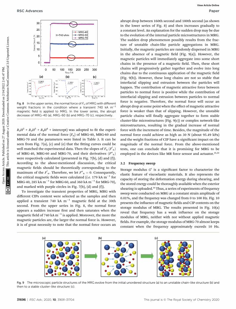
Fig. 8 In the upper series, the normal force of Fn of MRGwith differentweight fractions in the condition where a transient 740 kA m�1
magnetic field is applied to MRG. In the lower series, the abruptdecrease of MRG-40 (a), MRG-60 (b) and MRG-70 (c), respectively.
RSC Advances Paper
Ope
n A
cces
s A
rtic
le. P
ublis
hed
on 2
7 A
ugus
t 202
0. D
ownl
oade
d on
2/1
4/20
22 2
:41:
47 P
M.
Thi
s ar
ticle
is li
cens
ed u
nder
a C
reat
ive
Com
mon
s A
ttrib
utio
n-N
onC
omm
erci
al 3
.0 U
npor
ted
Lic
ence
.View Article Online
B2H2 + B3H
3 + B4H4 + intercept) was adopted to t the experi-
mental data of the normal force (Fn) of MRG-40, MRG-60 andMRG-70 and the parameters were listed in Table 3. It can beseen from Fig. 7(a), (c) and (e) that the tting curves could bewell matched the experimental data. Then the slopes of Fn ðF 0
nÞof MRG-40, MRG-60 and MRG-70, and their derivatives ðF 00
nÞwere respectively calculated (presented in Fig. 7(b), (d) and (f)).According to the above-mentioned discussion, the criticalmagnetic elds should be theoretically corresponding to themaximum of the F 0
n: Therefore, we let F 00n ¼ 0: Consequently,
the critical magnetic elds were calculated (i.e. 179 kA m�1 forMRG-40, 285 kA m�1 for MRG-60, and 360 kA m�1 for MRG-70),and marked with purple circles in Fig. 7(b), (d) and (f)).
To investigate the transient properties of MRG, MRG withdifferent CIPs content were selected as the samples and thenapplied a transient 740 kA m�1 magnetic eld at the 30thsecond. From the upper series in Fig. 8, the normal forceappears a sudden increase rst and then saturates when themagnetic eld of 740 kA m�1 is applied. Moreover, the more themagnetic particles are, the larger the normal force is. However,it is of great necessity to note that the normal force occurs an
Fig. 9 The microscopic particle structures of the MRG evolve from the inthen to a stable cluster-like structure (c).
31696 | RSC Adv., 2020, 10, 31691–31704
abrupt drop between 160th second and 180th second (as shownin the lower series of Fig. 8) and then increases gradually toa constant level. An explanation for the sudden dropmay be dueto the evolution of the internal particle microstructures inMRG.The sudden drop phenomenon possibly results from the frac-ture of unstable chain-like particle aggregations in MRG.Initially, the magnetic particles are randomly dispersed in MRGin the absence of a magnetic eld (Fig. 9(a)). However, themagnetic particles will immediately aggregate into some shortchains in the presence of a magnetic eld. Then, these shortchains will progressively gather together and evolve into longchains due to the continuous application of the magnetic eld(Fig. 9(b)). However, these long chains are not so stable thatinterfacial slipping and extrusion between the particles willhappen. The contribution of magnetic attractive force betweenparticles to normal force is positive while the contribution ofinterfacial slipping and extrusion between particles to normalforce is negative. Therefore, the normal force will occur anabrupt drop at some point when the effect of magnetic attractiveforce is weaker than that of slipping. However, the unstableparticle chains will nally aggregate together to form stablecluster-like microstructures (Fig. 9(c)) or complex network-likemicrostructures, resulting in the gradual increase of normalforce with the increment of time. Besides, the magnitude of thenormal force could achieve as high as 30 N (about 95.49 kPa)and the weight fractions of CIP have a signicant impact on themagnitude of the normal force. From the above-mentionedtests, one can conclude that it is promising for MRG to beemployed in the devices like MR force sensor and actuator.31,32
3.2 Frequency sweep
Storage modulus G0 is a signicant factor to characterize theelastic feature of viscoelastic materials. It also represents thecapacity of storing the deformation energy during shearing, andthe stored energy could be thoroughly available when the exteriorshearing is uploaded.33 Thus, a series of experiments of frequencysweep were conducted on MRG at a constant strain amplitude of0.01%, and the frequency was changed from 0 to 100 Hz. Fig. 10presents the inuence ofmagnetic elds and CIP contents on thestorage modulus of MRG. The results presented in Fig. 10(a)reveal that frequency has a weak inuence on the storagemodulus of MRG, neither with nor without applied magneticelds. For example, the storagemodulus ofMRG-70 almost keepsconstant when the frequency approximately exceeds 10 Hz.
itial unordered structure (a) to an unstable chain-like structure (b) and
This journal is © The Royal Society of Chemistry 2020

Fig. 10 The storage modulus–frequency curves of MRG-70 under five different magnetic fields (a); the storage modulus–frequency curves ofMRG with different CIP fractions under constant magnetic fields (b).
Paper RSC Advances
Ope
n A
cces
s A
rtic
le. P
ublis
hed
on 2
7 A
ugus
t 202
0. D
ownl
oade
d on
2/1
4/20
22 2
:41:
47 P
M.
Thi
s ar
ticle
is li
cens
ed u
nder
a C
reat
ive
Com
mon
s A
ttrib
utio
n-N
onC
omm
erci
al 3
.0 U
npor
ted
Lic
ence
.View Article Online
Moreover, it could be seen from Fig. 10(a) that the inuence ofmagnetic elds on the storage modulus of MRG showsa decreasing trend with increasing of magnetic elds, resultingfrom the gradually saturated magnetic particles in MRG.34
Therefore, the gaps between the steady-state value of storagemodulus decrease progressively with the increasing of magneticelds.35 On the other hand, taking MRG-40 for example, storagemodulus appears a rising trend with the enlargement offrequency at rst and then gets a plateau gradually. Fig. 10(b) alsodemonstrates that the CIP contents of MRG have a strong effecton the storage modulus, i.e. MRG with more magnetic particlesusually achieves a larger storage modulus.
Fig. 11 The shear stress–strain curves of MRG-60 under different shear r
This journal is © The Royal Society of Chemistry 2020
3.3 Quasi-static properties of MRG under monotonic shearmode
To understand the shear rate-dependent properties of MRG,MRG-60 was selected as a test sample. The variations of shearstress with shear strain for MRG-60 under four different shearrates and constant magnetic elds are displayed in Fig. 11. Inthe absence of a magnetic eld, the shear stress appears anabrupt increment rstly and then gets a gradual plateau withthe increasing of shear strain when the shear rates are set as0.005 s�1 and 0.02 s�1. However, the shear stress gets up toa maximum value rstly and then decreases to a steady-statevalue which is slightly smaller than the maximum value whenthe shear rates are set as 0.04 s and 0.083 s�1. These phenomena
ates with 0 kA m�1 (a); 96 kA m�1 (b); 194 kA m�1 (c) and 391 kA m�1 (d).
RSC Adv., 2020, 10, 31691–31704 | 31697

RSC Advances Paper
Ope
n A
cces
s A
rtic
le. P
ublis
hed
on 2
7 A
ugus
t 202
0. D
ownl
oade
d on
2/1
4/20
22 2
:41:
47 P
M.
Thi
s ar
ticle
is li
cens
ed u
nder
a C
reat
ive
Com
mon
s A
ttrib
utio
n-N
onC
omm
erci
al 3
.0 U
npor
ted
Lic
ence
.View Article Online
indicate that there is a threshold between the 0.02 s�1 and 0.04s�1. However, these phenomena will disappear in the presenceof a magnetic eld, i.e. the shear stress evenly trends stable aera sudden increment, which is different from the MR grease36
and MR plastomer.37 Another notable characteristic is that theinuence of shear rate on the shear stress will be negligiblegradually with the increasing of the external magnetic eld.There is almost no discrepancy between the shear stress underdifferent shear rates (Fig. 11(d)) at the 391 kA m�1 magneticstrength and it is not the phenomena of wall slip aer conr-mations. This may be ascribed to the formation of the similarcolumn-like or cluster-like microstructures and the highdamping performance originated from the microstructures inMRG when the magnetic eld is strong enough.
3.4 Magneto-induced damping performance of MRG undercyclic shear mode
In this section, the inuence of CIPs content, shear rate andshear strain amplitude on the damping performance of MRGunder different magnetic elds will be discussed. As mentionedbefore, MRG is promising to be used in vibration controldevices such as MR damper. MRG can dissipate the energy andattenuate the damage when it is exposed to the vibration causedby external motivation. Therefore, it is necessary to study theenergy dissipation density under quasi-statically and cyclicallyshearing conditions. As known, the area surrounded by theshear stress–strain curve represents the energy dissipationdensity of MRG. The larger the area is, the larger the energy
Fig. 12 The shear stress–strain curves of MRG with different CIP contentkA m�1 (c) and 391 kA m�1 (d).
31698 | RSC Adv., 2020, 10, 31691–31704
dissipation density is, and the better the damping performanceof MRG is.38 The area of shear stress–strain curve could bequantitatively calculated using the following integral formula:
Ed ¼Þsdg (1)
where, Ed represents the area enclosed by the shear stress–strain curve (i.e. the dissipated energy density). s and g repre-sent shear stress and shear strain, respectively.
3.4.1 Magneto-induced damping performance of MRGwith different CIP contents. Fig. 12 presents the inuence ofCIPs content on the shear stress–strain curves of MRG underfour constant magnetic elds. The shear rate and shear strainare kept as 0.04 s�1 and 100%, respectively. From Fig. 12, theshear stress–strain curves of MRG with different CIP contentspresent parallelogram-like shapes without a magnetic eld,polygon-like shapes in magnetic elds of 96 and 194 kA m�1,and ellipse-like shapes in a magnetic eld of 391 kA m�1,respectively. This phenomenon indicates that the externalmagnetic eld, compared with the CIP content, has a strongereffect on the shape of the shear stress–strain curves.
Taking MRG-70 for example, the changing regularity of theeld-dependent shapes of shear stress–strain curves under fourconstant magnetic elds is shown in Fig. 13. The shear stress–strain curve displays a closed parallelogram-like shape in theabsence of a magnetic eld while it displays a gapped polygon-like shape and a gapped ellipse-like shape in the presence ofa magnetic eld (marked by the blue dotted lines in Fig. 13).Moreover, the shear stress appears a sudden decrease (or
s under constant shear rate of 0.04 s�1. 0 kA m�1 (a); 96 kA m�1 (b); 194
This journal is © The Royal Society of Chemistry 2020
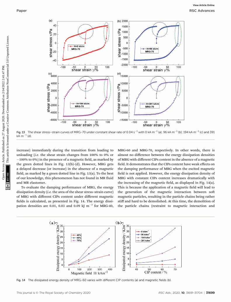
Fig. 13 The shear stress–strain curves of MRG-70 under constant shear rate of 0.04 s�1 with 0 kA m�1 (a); 96 kA m�1 (b); 194 kA m�1 (c) and 391kA m�1 (d).
Paper RSC Advances
Ope
n A
cces
s A
rtic
le. P
ublis
hed
on 2
7 A
ugus
t 202
0. D
ownl
oade
d on
2/1
4/20
22 2
:41:
47 P
M.
Thi
s ar
ticle
is li
cens
ed u
nder
a C
reat
ive
Com
mon
s A
ttrib
utio
n-N
onC
omm
erci
al 3
.0 U
npor
ted
Lic
ence
.View Article Online
increase) immediately during the transition from loading tounloading (i.e. the shear strain changes from 100% to 0% or�100% to 0%) in the presence of a magnetic eld, as marked bythe green dotted lines in Fig. 13(b)–(d). However, MRG getsa delayed decrease (or increase) in the absence of a magneticeld, as marked by a green dotted line in Fig. 13(a). To the bestof our knowledge, this phenomenon has not found in MR uidand MR elastomer.
To evaluate the damping performance of MRG, the energydissipation density (i.e. the area of the shear stress–strain curve)of MRG with different CIPs content under different magneticelds is calculated, as presented in Fig. 14. The energy dissi-pation densities are 0.01, 0.03 and 0.09 kJ m�3 for MRG-40,
Fig. 14 The dissipated energy density of MRG-60 varies with different C
This journal is © The Royal Society of Chemistry 2020
MRG-60 and MRG-70, respectively. In other words, there isalmost no difference between the energy dissipation densitiesof MRG with different CIPs content in the absence of a magneticeld. It demonstrates that the CIPs content have weak effects onthe damping performance of MRG when the excited magneticeld is not applied. However, the energy dissipation density ofMRG with constant CIPs content increases dramatically withthe increasing of the magnetic eld, as displayed in Fig. 14(a).This is because the application of a magnetic eld will lead tothe generation of the magnetic interaction between somagnetic particles, resulting in the particle chains being ratherstiff and hard to be demolished. At this time, the demolition ofthe particle chains (restraint to magnetic interaction and
IP contents (a) and magnetic fields (b).
RSC Adv., 2020, 10, 31691–31704 | 31699

Fig. 15 The shear stress–strain curves of MRG-60 under different shear rates. 0 kA m�1 (a); 96 kA m�1 (b); 194 kA m�1 (c) and 391 kA m�1 (d).
RSC Advances Paper
Ope
n A
cces
s A
rtic
le. P
ublis
hed
on 2
7 A
ugus
t 202
0. D
ownl
oade
d on
2/1
4/20
22 2
:41:
47 P
M.
Thi
s ar
ticle
is li
cens
ed u
nder
a C
reat
ive
Com
mon
s A
ttrib
utio
n-N
onC
omm
erci
al 3
.0 U
npor
ted
Lic
ence
.View Article Online
interface slipping between particles) is the main mechanism ofenergy dissipation behavior. Therefore, more energy is neededto destroy the particle chains in the presence of amagnetic eld.The magnetic interaction between particles increases with themagnetic eld, which demonstrates that the energy dissipationdensity is highly dependent on the excited magnetic eld.Fig. 14(b) also implies that MRG with larger CIPs contentusually possesses larger energy dissipation density and bettermagneto-induced damping performance when the excitedmagnetic eld is constant. Apparently, the larger the CIPscontent of MRG is, the more particle chains will form undera constant magnetic eld. Therefore, it will consume moreenergy to break the particle chains. More energy is dissipated byMRG with higher CIPs content. Moreover, the dissipated energydensity of MRG-70 reaches as high as 32.95 kJ m�3 under themagnetic eld of 391 kA m�1.
Table 4 The energy dissipation density of MRG-60 under different shea
Energy dissipation density/kJ m�3
Shear rate/s�1
0.005 0.02 0
Magnetic eld/kA m�1 0 0.022 0.026 096 2.47 2.65 3194 9.45 9.86 1391 23.10 23.40 2
Magneto-induced enhancementEd 391 kA m�1 � Ed 0 kA m�1
Ed 0 kA m�1� 100%
104 900% 89 900% 7
31700 | RSC Adv., 2020, 10, 31691–31704
3.4.2 Magneto-induced damping performance of MRGwith different shear rates. Fig. 15 presents the variation of shearstress with shears strain for MRG-60 under different shear ratesand constant magnetic elds. The shape-changing regularity ofshear stress–strain curve of MRG-60 under different shear ratesand magnetic elds is similar to that of MRG discussed inSection 3.4.1. It will not be discussed here for simplicity. Theenergy dissipation densities are 0.022, 0.026, 0.03 and 0.04 kJm�3 for shear rates of 0.005, 0.02, 0.04 and 0.083 s�1 respec-tively when the magnetic eld is not applied. This indicates theshear rate has a certain inuence on the damping performanceof MRG in the absence of a magnetic eld. However, theinuence decreases gradually with the increasing of themagnetic eld, as shown in Fig. 15(b)–(d). It also can be seenfrom Fig. 15(d) that the shear stress–strain curves for differentshear rates nearly coincide in the magnetic eld of 391 kA m�1.
r rates and different magnetic fields
Shear rate-induced enhancementEd 0:083 s�1 � Ed 0:005 s�1
Ed 0:005 s�1� 100%.04 0.083
.03 0.04 82%
.15 3.28 33%0.06 10.62 12%3.51 23.48 2%8 267% 58 600%
This journal is © The Royal Society of Chemistry 2020

Paper RSC Advances
Ope
n A
cces
s A
rtic
le. P
ublis
hed
on 2
7 A
ugus
t 202
0. D
ownl
oade
d on
2/1
4/20
22 2
:41:
47 P
M.
Thi
s ar
ticle
is li
cens
ed u
nder
a C
reat
ive
Com
mon
s A
ttrib
utio
n-N
onC
omm
erci
al 3
.0 U
npor
ted
Lic
ence
.View Article Online
This transition also implies that the external magnetic eld ismuch more inuential than the shear rate on the dampingperformance of MRG. Table 4 shows the energy dissipationdensity of MRG-60 under different magnetic elds and shearrates. As shown in Table 4, the magneto-induced enhancingeffect on damping performance is 104 900% under the shearrate of 0.005 s�1, which is nearly twice than that under the shearrate of 0.083 s�1. A time-dependent explanation could be usedto interpret this phenomenon. When the shear rate (i.e. 0.005s�1) is relatively small, the magnetic eld is given long enoughtime (i.e. 200 s) to drive the transformation of microstructuresfrom unordered state to steady state. However, under a rela-tively larger shear rate of 0.083 s�1, the transformation of themicrostructures is mainly driven by the shear-induced defor-mation instead of the magnetic eld. It is because the magneticeld can only drive the transformation of microstructure partlydue to relatively less time (i.e. 12 s). As discussed in 3.4.1, themagnetic eld is the primary inuencing factor in the evolutionof interior microstructures. Thus, the microstructures do notevolve completely due to the limitation of time when the shearrate is relatively larger. Consequently, the magneto-inducedenhancing effect on damping performance decreases with theincrease of shear rate.
3.4.3 Magneto-induced damping performance of MRGwith different shear strain amplitude. The inuence of shearstrain amplitude on shear–strain curves under four differentconstant magnetic elds can be intuitively seen in Fig. 16. Theexperiments are conducted under different shear strain
Fig. 16 The shear stress–strain curves of MRG-60 under different shearm�1 (d).
This journal is © The Royal Society of Chemistry 2020
amplitudes of 20%, 40%, 60%, 80% and 100%, respectively anda constant shear rate of 0.04 s�1. The changing regularity of theeld-dependent shapes of shear stress–strain curves underdifferent shear strain amplitudes and constant magnetic eldsis the same as that discussed in Section 3.4.1 and 3.4.2 and willnot be repeated here. When the shear strain amplitude is rela-tively small (e.g. 20%), the maximum shear stress is smallerthan that under the shear strain amplitude of 100%. Thisphenomenon is especially obvious in the absence of a magneticeld. However, when the shear strain is larger than 40%, thereis almost no discrepancy between the maximum shear stressesin the presence of a magnetic eld. These phenomena manifestthat the external magnetic eld has weak effects on themaximum shear stress of MRG under different shear strainamplitudes when the magnetic strength is constant. Neverthe-less, it has strong effects on the energy dissipation density ofMRG under the different strain amplitudes, which can beintuitively observed from Fig. 16. Therefore, Fig. 17 is presentedto better understand the magneto-induced enhancing effectand shear strain-induced enhancing effect on the energy dissi-pation density of MRG. As shown in Fig. 17(a), the magneticstrength of 96 kA m�1 is a critical value for the entire testedshear strain amplitude (i.e. 20%, 40%, 60%, 80% and 100%). Inother words, when the magnetic strength is larger than 96 kAm�1, the slope of the curve is much steeper than that under themagnetic strength being smaller than 96 kA m�1. Thisdemonstrates the magneto-induced enhancing effect on theenergy dissipation density performs a qualitative leap when the
strain amplitude. 0 kA m�1 (a); 96 kA m�1 (b); 194 kA m�1 (c) and 391 kA
RSC Adv., 2020, 10, 31691–31704 | 31701
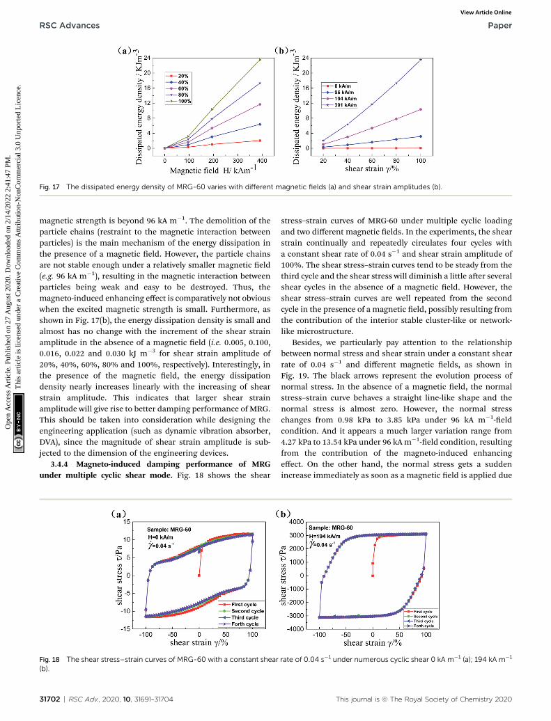
Fig. 17 The dissipated energy density of MRG-60 varies with different magnetic fields (a) and shear strain amplitudes (b).
RSC Advances Paper
Ope
n A
cces
s A
rtic
le. P
ublis
hed
on 2
7 A
ugus
t 202
0. D
ownl
oade
d on
2/1
4/20
22 2
:41:
47 P
M.
Thi
s ar
ticle
is li
cens
ed u
nder
a C
reat
ive
Com
mon
s A
ttrib
utio
n-N
onC
omm
erci
al 3
.0 U
npor
ted
Lic
ence
.View Article Online
magnetic strength is beyond 96 kA m�1. The demolition of theparticle chains (restraint to the magnetic interaction betweenparticles) is the main mechanism of the energy dissipation inthe presence of a magnetic eld. However, the particle chainsare not stable enough under a relatively smaller magnetic eld(e.g. 96 kA m�1), resulting in the magnetic interaction betweenparticles being weak and easy to be destroyed. Thus, themagneto-induced enhancing effect is comparatively not obviouswhen the excited magnetic strength is small. Furthermore, asshown in Fig. 17(b), the energy dissipation density is small andalmost has no change with the increment of the shear strainamplitude in the absence of a magnetic eld (i.e. 0.005, 0.100,0.016, 0.022 and 0.030 kJ m�3 for shear strain amplitude of20%, 40%, 60%, 80% and 100%, respectively). Interestingly, inthe presence of the magnetic eld, the energy dissipationdensity nearly increases linearly with the increasing of shearstrain amplitude. This indicates that larger shear strainamplitude will give rise to better damping performance of MRG.This should be taken into consideration while designing theengineering application (such as dynamic vibration absorber,DVA), since the magnitude of shear strain amplitude is sub-jected to the dimension of the engineering devices.
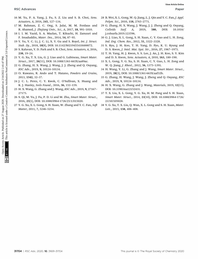
3.4.4 Magneto-induced damping performance of MRGunder multiple cyclic shear mode. Fig. 18 shows the shear
Fig. 18 The shear stress–strain curves of MRG-60 with a constant shear(b).
31702 | RSC Adv., 2020, 10, 31691–31704
stress–strain curves of MRG-60 under multiple cyclic loadingand two different magnetic elds. In the experiments, the shearstrain continually and repeatedly circulates four cycles witha constant shear rate of 0.04 s�1 and shear strain amplitude of100%. The shear stress–strain curves tend to be steady from thethird cycle and the shear stress will diminish a little aer severalshear cycles in the absence of a magnetic eld. However, theshear stress–strain curves are well repeated from the secondcycle in the presence of a magnetic eld, possibly resulting fromthe contribution of the interior stable cluster-like or network-like microstructure.
Besides, we particularly pay attention to the relationshipbetween normal stress and shear strain under a constant shearrate of 0.04 s�1 and different magnetic elds, as shown inFig. 19. The black arrows represent the evolution process ofnormal stress. In the absence of a magnetic eld, the normalstress–strain curve behaves a straight line-like shape and thenormal stress is almost zero. However, the normal stresschanges from 0.98 kPa to 3.85 kPa under 96 kA m�1-eldcondition. And it appears a much larger variation range from4.27 kPa to 13.54 kPa under 96 kA m�1-eld condition, resultingfrom the contribution of the magneto-induced enhancingeffect. On the other hand, the normal stress gets a suddenincrease immediately as soon as a magnetic eld is applied due
rate of 0.04 s�1 under numerous cyclic shear 0 kA m�1 (a); 194 kA m�1
This journal is © The Royal Society of Chemistry 2020

Fig. 19 The normal stress–strain curves of MRG-60 with a constantshear rate of 0.04 s�1 under numerous cyclic shear and differentmagnetic fields. The black arrows represent the evolution of normalstress of MRG-60 along with shear strain.
Paper RSC Advances
Ope
n A
cces
s A
rtic
le. P
ublis
hed
on 2
7 A
ugus
t 202
0. D
ownl
oade
d on
2/1
4/20
22 2
:41:
47 P
M.
Thi
s ar
ticle
is li
cens
ed u
nder
a C
reat
ive
Com
mon
s A
ttrib
utio
n-N
onC
omm
erci
al 3
.0 U
npor
ted
Lic
ence
.View Article Online
to the contribution of magneto-induced cluster-like structures.This proves that the randomly dispersed particles in MRG willchange into ordered particle chain microstructure withinmilliseconds. Then, normal stress begins to decrease andplateaus to a minimum value (0.98 and 4.27 kPa in the magneticeld of 96 kA m�1 and 194 kA m�1, respectively). The rebuildingand fracture of the internal particle chain microstructures carryout simultaneously and their contributions to the normal stressare contrary. When the inuence of the fracture (such as thegradually enlarged gap between particles and the incline of theparticle chain, etc.) is larger than that of the rebuilding, thenormal stress will fall. On the contrary, normal stress will moveup when the inuence of rebuilding is larger than that of frac-ture. Then, the internal particle chain microstructure starts torebuild and contribute to the increasing of normal stress againwhen the shear strain inversely approaches 0% aer it reaches100%. However, the reconstructive internal microstructure willbe destroyed again due to the gradual change of the shearingdeformation, resulting in the emergence of peaks of normalstress (i.e. 3.85 and 13.54 kPa under a magnetic eld of 96 and194 kA m�1, respectively).
4. Conclusion
In this paper, two kinds of experiments, (i.e., magneto-inducedlarge deformation shear and magneto-induced dampingperformance under quasi-statically and cyclically condition,respectively), were conducted to investigate the rheologicalproperties of MRG. The excited magnetic eld has a strongeffect on the shear stress and normal force by transforming theinterior microstructure in MRG, which indirectly results in themagneto-induced large deformation and enhancing dampingperformance. The magneto-induced normal force increaseswith the increment of the magnetic eld, and the speed of theincrement rstly increases rapidly and then slows down grad-ually. The normal force of MRG-70 could be adjusted in a largerange from 0 to 30 N (95.4 kPa) in the magnetic strength of 740kA m�1. In the quasi-static monotonic shear test, the inuenceof shear rate on magneto-induced shear stress is nearly negli-gible when the magnetic eld is strong enough. From the
This journal is © The Royal Society of Chemistry 2020
discussion on the energy dissipation density of MRG under thecyclic shear mode, the shape-changing regularity of shearstress–strain curve is mainly inuenced by the externalmagnetic eld. Magneto-induced damping performance ofMRG is highly relevant to the external actuating conditions (i.e.CIP content, shear rate, shear strain amplitude and magneticeld). The magneto-induced enhanced damping performanceof MRG-60 could attain 104 900% in the magnetic strength of391 kA m�1 while it will signicantly reduce with the increasingof shear rate. Besides, one can conclude that the larger the shearstrain amplitude, the larger the energy dissipation density, thebetter the damping performance of MRG. This work will provideeffective guideline for the design of MR devices used for vibra-tion controlling (such as dynamic vibration absorber), which isour main work of the next stage.
Conflicts of interest
There is no conict to declare.
Acknowledgements
The work of this paper has been supported by a NationalNatural Foundation of China (No. 51675280).
Reference
1 T. Shiga, A. Okada and T. Kurauchi, J. Appl. Polym. Sci., 1995,58, 787–792.
2 G. Zhang, Y. C. Li, H. X. Wang and J. Wang, Front. Mater.,2019, 6(56), DOI: 10.3389/fmats.2019.00056.
3 N. Dogdu, I. Uslan, S. Yuksel and Z. Parlak, J. Mech. Sci.Technol., 2019, 33, 3885–3893.
4 Y. Rabbani, M. Ashtiani and S. H. Hashemabadi, SoMatter,2015, 11, 4453–4460.
5 J. K. Wu, X. L. Gong, Y. C. Fan and H. S. Xia, Smart Mater.Struct., 2010, 19(10), DOI: 10.1088/0964-1726/19/10/105007.
6 G. J. Liao, Y. G. Xu, F. J. Wang, F. Y. Wei and Q. Wan, Mater.Lett., 2016, 174, 79–81.
7 M. Ashtiani, S. H. Hashemabadi and A. Ghaffari, J. Magn.Magn. Mater., 2015, 374, 716–730.
8 S. H. Kwon, H. S. Jung, H. J. Choi, Z. Strecker and J. Roupec,Colloids Surf. A, 2018, 555, 685–690.
9 M. Bunoiu and J. Bica, J. Ind. Eng. Chem., 2016, 37, 312–318.10 Y. C. Li, J. C. Li, W. H. Li and B. Samali, Smart Mater. Struct.,
2013, 22(3), DOI: 10.1088/0964-1726/22/3/035005.11 R. Ahamed, S. B. Choi and M. M. Ferdaus, J. Intel. Mat. Syst.
Str., 2018, 29, 2051–2095.12 L. R. Wang, M. Yu, J. Fu and S. Qi, Smart Mater. Struct., 2018,
27(10), DOI: 10.1088/1361-665X/aadf3e.13 P. Dhar, A. Katiyar, A. Pattamatta and S. K. Das, Colloids Surf.
A, 2017, 530, 218–226.14 C. L. Sun, H. M. Pang, S. H. Xuan and X. L. Gong,Mater. Lett.,
2019, 256, DOI: 10.1016/j.matlet.2019.126611.15 M. Yu, H. P. Luo, J. Fu and P. A. Yang, J. Intel. Mat. Syst. Str.,
2018, 29, 24–31.
RSC Adv., 2020, 10, 31691–31704 | 31703
RSC Advances Paper
Ope
n A
cces
s A
rtic
le. P
ublis
hed
on 2
7 A
ugus
t 202
0. D
ownl
oade
d on
2/1
4/20
22 2
:41:
47 P
M.
Thi
s ar
ticle
is li
cens
ed u
nder
a C
reat
ive
Com
mon
s A
ttrib
utio
n-N
onC
omm
erci
al 3
.0 U
npor
ted
Lic
ence
.View Article Online
16 M. Yu, P. A. Yang, J. Fu, S. Z. Liu and S. B. Choi, Sens.Actuators, A, 2016, 245, 127–134.
17 M. Rahman, Z. C. Ong, S. Julai, M. M. Ferdaus andR. Ahamed, J. Zhejiang Univ., Sci., A, 2017, 18, 991–1010.
18 I. I. M. Yazid, S. A. Mazlan, T. Kikuchi, H. Zamzuri andF. Imaduddin, Mater. Des., 2014, 54, 87–95.
19 Y. Yu, Y. C. Li, J. C. Li, X. Y. Gu and S. Royel, Int. J. Struct.Stab. Dy., 2018, 18(8), DOI: 10.1142/S0219455418400072.
20 S. Kaluvan, Y. D. Park and S. B. Choi, Sens. Actuators, A, 2016,238, 19–24.
21 Y. G. Xu, T. X. Liu, G. J. Liao and G. Lubineau, Smart Mater.Struct., 2017, 26(11), DOI: 10.1088/1361-665X/aa89ac.
22 G. Zhang, H. X. Wang, J. Wang, J. J. Zheng and Q. Ouyang,RSC Adv., 2019, 9, 10124–10134.
23 O. Kuwano, R. Ando and T. Hatano, Powders and Grains,2013, 1542, 32–37.
24 J. C. L. Perez, C. Y. Kwok, C. O'Sullivan, X. Huang andK. J. Hanley, Soils Found., 2016, 56, 152–159.
25 H. X. Wang, G. Zhang and J. Wang, RSC Adv., 2019, 9, 27167–27175.
26 S. Qi, M. Yu, J. Fu, P. D. Li and M. Zhu, Smart Mater. Struct.,2016, 25(1), DOI: 10.1088/0964-1726/25/1/015020.
27 Y. G. Xu, X. L. Gong, S. H. Xuan, W. Zhang and Y. C. Fan, SoMatter, 2011, 7, 5246–5254.
31704 | RSC Adv., 2020, 10, 31691–31704
28 B. Wei, X. L. Gong, W. Q. Jiang, L. J. Qin and Y. C. Fan, J. Appl.Polym. Sci., 2010, 118, 2765–2771.
29 G. Zhang, H. X. Wang, J. Wang, J. J. Zheng and Q. Ouyang,Colloids Surf. A, 2019, 580, DOI: 10.1016/j.colsurfa.2019.123596.
30 G. J. Liao, X. L. Gong, S. H. Xuan, C. Y. Guo and L. H. Zong,Ind. Eng. Chem. Res., 2012, 51, 3322–3328.
31 S. Ryu, J. H. Koo, T. H. Yang, D. Pyo, K. U. Kyung andD. S. Kwon, J. Intel. Mat. Syst. Str., 2016, 27, 1967–1975.
32 T. H. Yang, H. J. Kwon, S. S. Lee, J. An, J. H. Koo, S. Y. Kimand D. S. Kwon, Sens. Actuators, A, 2010, 163, 180–190.
33 X. L. Gong, Y. G. Xu, S. H. Xuan, C. Y. Guo, L. H. Zong andW. Q. Jiang, J. Rheol., 2012, 56, 1375–1391.
34 H. Wang, Y. Li, G. Zhang and J. Wang, Smart Mater. Struct.,2019, 28(3), DOI: 10.1088/1361-665X/aaf32b.
35 G. Zhang, H. Wang, J. Wang, J. Zheng and Q. Ouyang, RSCAdv., 2019, 9, 10124–10134.
36 H. X. Wang, G. Zhang and J. Wang, Materials, 2019, 12(15),DOI: 10.3390/ma12152431.
37 T. X. Liu, X. L. Gong, Y. G. Xu, H. M. Pang and S. H. Xuan,Smart Mater. Struct., 2014, 23(10), DOI: 10.1088/0964-1726/23/10/105028.
38 Y. G. Xu, T. X. Liu, Q. Wan, X. L. Gong and S. H. Xuan,Mater.Lett., 2015, 158, 406–408.
This journal is © The Royal Society of Chemistry 2020