Magnetism Britannica Online Encyclopedia
11
magnetism magnetism, phenomenon associated with the motion of electric charges. This motion can take many forms. It can be an electric current in a conductor or charged particles moving through space , or it can be the motion of an electron in atomic orbit. Magnetism is also associated with elementary particles, such as the electron, that have a property called spin. Basic to magnetism are magnetic fields and their effects on matter, as, for instance, the deflection of moving charges and torques on other magnetic objects. Evidence for the presence of a magnetic field is the magnetic force on charges moving in that field; the force is at right angles to both the field and the velocity of the charge. This force deflects the particles without changing their speed. The deflection can be observed in t he electron beam of a television tube when a permanent magnet is brought near the tube. A more familiar example is the torque on a compass needle that acts to align the needle with the magnetic field of the Earth. The needle is a thin piece of iron that has been magnetized—i.e., a small bar magnet. One end of the magnet is called a north pole and the other end a south pole. The force between a north and a south pole is attractive, whereas the force between like poles is repulsive. The magnetic field is sometimes referred to as magnetic induction or magnetic flux density; it is always symbolized by B. Magnetic fields are measured in units of tesla (T). (Another unit of measure commonly used for B is the ga uss, though it is no longer co nsidered a standard u nit. One gau ss equals 10 tesla.) A fundamental property of a magnetic field is that its flux through any closed surface vanishes. (A closed surface is one that completely surrounds a volume.) This is expressed mathematica lly by div B = 0 and can be understood physically in terms of the field lines representing B. These lines always close on themselves, so that if they enter a certain volume at some point, they must also leave that volume. In this respect, a magnetic field is quite different from an electric field. Electric field lines can begin and end on a charge, but no equivalent magnetic charge has been found in spite of many searches for so-called magnetic monopoles. The most common source of magnetic fields is the electric current loop. It may be an electric current in a circular conductor or the motion of an orbiting electron in an atom. Associated with both these types of current loops is a magnetic dipole moment, the value of which is iA, the product of the current and the area of the loop. In addition, electrons, protons, and neutrons in atoms have a magnetic dipole moment associated with their intrinsic spin; such magnetic dipole moments represent another important source of magnetic fields. A particle with a magnetic dipole moment is often referred to as a magnetic dipole. (A magnetic dipole may be thought of as a tiny bar magnet. It has the same magnetic field as such a magnet and behaves the same way in external magnetic fields.) When placed in an external magnetic field, a magnetic dipole can be subjected to a torque that tends to align it with the field; if the external field is not uniform, the dipole also can be subjected to a force. All matter exhibits magnetic properties to some degree. When placed in an inhomogeneou s field, matter is either attracted or repelled in the direction of the gradient of the field. This property is described by the magnetic susceptibility of the matter and depends on the degree of magnetization of the matter in the field. Magnetization depends on the size of the dipole moments of the atoms in a substance and the degree to which the dipole moments are aligned with respect to each other. Certain materials, such as iron, exhibit very strong magnetic properties because of the alignment of the magnetic moments of their atoms within certain small regions called domains. Under normal conditions, the various domains have fields that cancel, but they can be aligned with each other to produce extremely large magnetic fields. Various alloys, like NdFeB (an alloy of neodymium, iron, and boron), keep their domains aligned and are used to make permanent magnets. The strong magnetic field produced by a typical three-millimetre-thick magnet of this material is comparable to an electromagnet made of a copper loop carrying a current of several thousand amperes. In compariso n, the current in a typical light bulb is 0.5 ampere. Since aligning the domains of a material produces a magnet, disorganizing the orderly alignment destroys the magnetic properties of the material. Thermal agitation that results from heating a magnet to a high temperature destroys its magnetic properties. Magnetic fields vary widely in strength. Some representative values are given in the Table. Fundamentals −4 Table of Contents • Introduction • Fun dament al s • Magnet ic fiel d of s teady curren ts • Magnetic for ces Lorentz force Repulsion or attraction between two magnetic dipoles Magnetization effects in matter • Magnet ic pr operti es of matter Induced and permanent atomic magnetic dipoles Diamagnetism Paramagnetism Ferromagnetism Role of exchange interaction Remanence Antiferromagnetism Ferrimagnetism
-
Upload
srinivasosss -
Category
Documents
-
view
7 -
download
0
description
Magnetism
Transcript of Magnetism Britannica Online Encyclopedia
7/17/2019 Magnetism Britannica Online Encyclopedia
http://slidepdf.com/reader/full/magnetism-britannica-online-encyclopedia 1/11
magnetismmagnetism, phenomenon associated with the motion of electric charges.
This motion can take many forms. It can be an electric current in a
conductor or charged particles moving through space, or it can be the
motion of an electron in atomic orbit. Magnetism is also associated with
elementary particles, such as the electron, that have a property called spin.
Basic to magnetism are magnetic fields and their effects on matter, as, for
instance, the deflection of moving charges and torques on other magnetic
objects. Evidence for the presence of a magnetic field is the magnetic force
on charges moving in that field; the force is at right angles to both the field
and the velocity of the charge. This force deflects the particles without
changing their speed. The deflection can be observed in the electron beam
of a television tube when a permanent magnet is brought near the tube. A
more familiar example is the torque on a compass needle that acts to align
the needle with the magnetic field of the Earth. The needle is a thin piece of iron that has been magnetized—i.e., a small bar
magnet. One end of the magnet is called a north pole and the other end a south pole. The force between a north and a south
pole is attractive, whereas the force between like poles is repulsive. The magnetic field is sometimes referred to as magneticinduction or magnetic flux density; it is always symbolized by B. Magnetic fields are measured in units of tesla (T). (Another unit
of measure commonly used for B is the gauss, though it is no longer considered a standard unit. One gauss equals 10 tesla.)
A fundamental property of a magnetic field is that its flux through any closed surface vanishes. (A closed surface is one that
completely surrounds a volume.) This is expressed mathematically by div B = 0 and can be understood physically in terms of the
field lines representing B. These lines always close on themselves, so that if they enter a certain volume at some point, they must
also leave that volume. In this respect, a magnetic field is quite different from an electric field. Electric field lines can begin and
end on a charge, but no equivalent magnetic charge has been found in spite of many searches for so-called magnetic
monopoles.
The most common source of magnetic fields is the electric current loop. It may be an electric current in a circular conductor or
the motion of an orbiting electron in an atom. Associated with both these types of current loops is a magnetic dipole moment,
the value of which is iA, the product of the current and the area of the loop. In addition, electrons, protons, and neutrons in
atoms have a magnetic dipole moment associated with their intrinsic spin; such magnetic dipole moments represent anotherimportant source of magnetic fields. A particle with a magnetic dipole moment is often referred to as a magnetic dipole. (A
magnetic dipole may be thought of as a tiny bar magnet. It has the same magnetic field as such a magnet and behaves the same
way in external magnetic fields.) When placed in an external magnetic field, a magnetic dipole can be subjected to a torque that
tends to align it with the field; if the external field is not uniform, the dipole also can be subjected to a force.
All matter exhibits magnetic properties to some degree. When placed in an inhomogeneous field, matter is either attracted or
repelled in the direction of the gradient of the field. This property is described by the magnetic susceptibility of the matter and
depends on the degree of magnetization of the matter in the field. Magnetization depends on the size of the dipole moments of
the atoms in a substance and the degree to which the dipole moments are aligned with respect to each other. Certain materials,
such as iron, exhibit very strong magnetic properties because of the alignment of the magnetic moments of their atoms within
certain small regions called domains. Under normal conditions, the various domains have fields that cancel, but they can be
aligned with each other to produce extremely large magnetic fields. Various alloys, like NdFeB (an alloy of neodymium, iron, and
boron), keep their domains aligned and are used to make permanent magnets. The strong magnetic field produced by a typical
three-millimetre-thick magnet of this material is comparable to an electromagnet made of a copper loop carrying a current ofseveral thousand amperes. In comparison, the current in a typical light bulb is 0.5 ampere. Since aligning the domains of a
material produces a magnet, disorganizing the orderly alignment destroys the magnetic properties of the material. Thermal
agitation that results from heating a magnet to a high temperature destroys its magnetic properties.
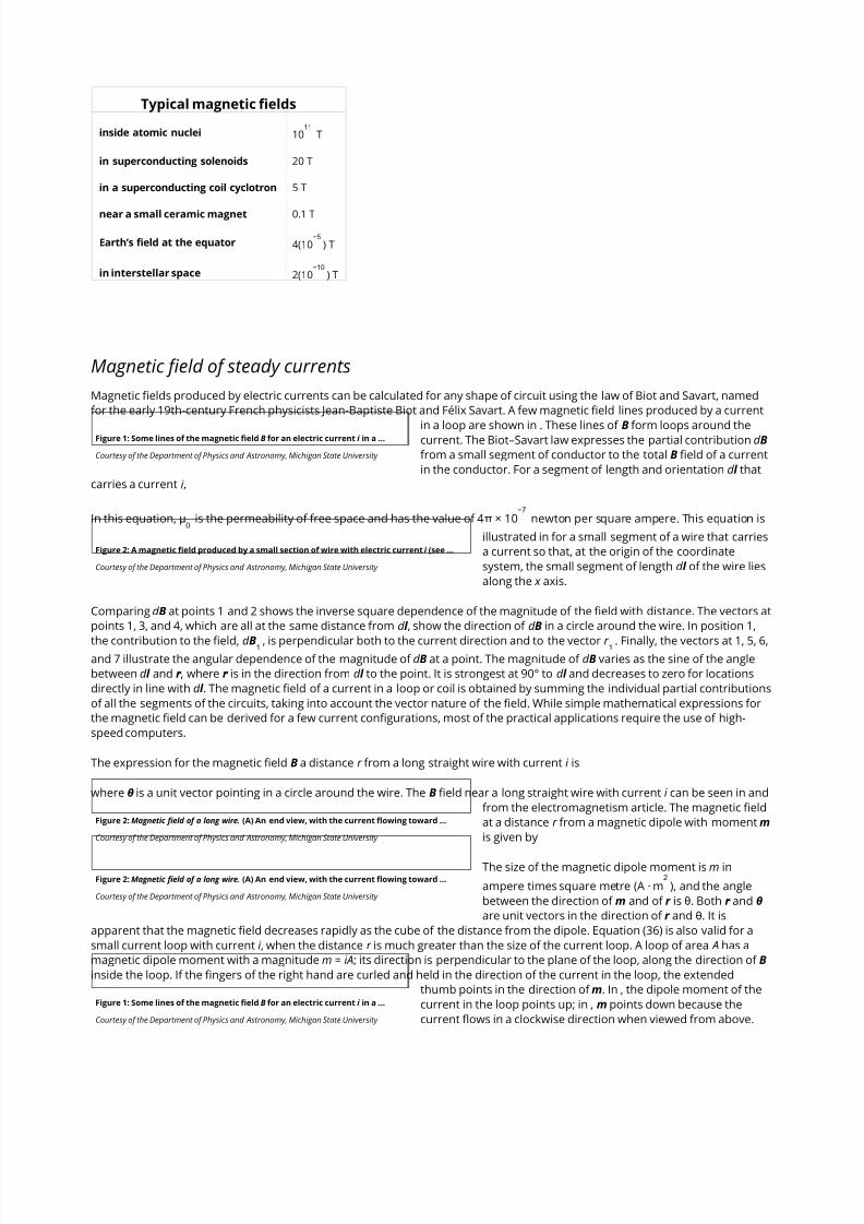
Magnetic fields vary widely in strength. Some representative values are given in the Table.
Fundamentals
−4
Table of Contents
• Introduction
• Fundamentals
• Magnetic field of steady currents
• Magnetic forces
Lorentz force
Repulsion or attraction between two magnetic
dipoles
Magnetization effects in matter
• Magnetic properties of matter
Induced and permanent atomic magnetic dipoles
Diamagnetism
Paramagnetism
Ferromagnetism
Role of exchange interaction
Remanence
Antiferromagnetism
Ferrimagnetism
7/17/2019 Magnetism Britannica Online Encyclopedia
http://slidepdf.com/reader/full/magnetism-britannica-online-encyclopedia 2/11
Figure 1: Some lines of the magnetic field B for an electric current i in a …
Courtesy of the Department of Physics and Astronomy, Michigan State University
Figure 2: A magnetic field produced by a small section of wire with electric current i (see …
Courtesy of the Department of Physics and Astronomy, Michigan State University
Figure 2: Magnetic field of a long wire. (A) An end view, with the current flowing toward …
Courtesy of the Department of Physics and Astronomy, Michigan State University
Figure 2: Magnetic field of a long wire. (A) An end view, with the current flowing toward …
Courtesy of the Department of Physics and Astronomy, Michigan State University
Figure 1: Some lines of the magnetic field B for an electric current i in a …
Courtesy of the Department of Physics and Astronomy, Michigan State University
Typical magnetic fields
inside atomic nuclei 10 T
in superconducting solenoids 20 T
in a superconducting coil cyclotron 5 T
near a small ceramic magnet 0.1 T
Earth’s field at the equator 4(10 ) T
in interstellar space 2(10 ) T
Magnetic fields produced by electric currents can be calculated for any shape of circuit using the law of Biot and Savart, named
for the early 19th-century French physicists Jean-Baptiste Biot and Félix Savart. A few magnetic field lines produced by a current
in a loop are shown in . These lines of B form loops around thecurrent. The Biot–Savart law expresses the partial contribution d B
from a small segment of conductor to the total B field of a current
in the conductor. For a segment of length and orientation d l that
carries a current i ,
In this equation, μ is the permeability of free space and has the value of 4π × 10 newton per square ampere. This equation is
illustrated in for a small segment of a wire that carries
a current so that, at the origin of the coordinate
system, the small segment of length d l of the wire lies
along the x axis.
Comparing d B at points 1 and 2 shows the inverse square dependence of the magnitude of the field with distance. The vectors at
points 1, 3, and 4, which are all at the same distance from d l , show the direction of d B in a circle around the wire. In position 1,
the contribution to the field, d B , is perpendicular both to the current direction and to the vector r . Finally, the vectors at 1, 5, 6,and 7 illustrate the angular dependence of the magnitude of d B at a point. The magnitude of d B varies as the sine of the angle
between d l and r ̂, where r ̂ is in the direction from d l to the point. It is strongest at 90° to d l and decreases to zero for locations
directly in line with d l . The magnetic field of a current in a loop or coil is obtained by summing the individual partial contributions
of all the segments of the circuits, taking into account the vector nature of the field. While simple mathematical expressions for
the magnetic field can be derived for a few current configurations, most of the practical applications require the use of high-
speed computers.
The expression for the magnetic field B a distance r from a long straight wire with current i is
where θ is a unit vector pointing in a circle around the wire. The B field near a long straight wire with current i can be seen in and
from the electromagnetism article. The magnetic field
at a distance r from a magnetic dipole with moment m
is given by
The size of the magnetic dipole moment is m in
ampere times square metre (A · m ), and the angle
between the direction of m and of r is θ. Both r ̂ and θ
are unit vectors in the direction of r and θ. It is
apparent that the magnetic field decreases rapidly as the cube of the distance from the dipole. Equation (36) is also valid for a
small current loop with current i , when the distance r is much greater than the size of the current loop. A loop of area A has a
magnetic dipole moment with a magnitude m = iA; its direction is perpendicular to the plane of the loop, along the direction of B
inside the loop. If the fingers of the right hand are curled and held in the direction of the current in the loop, the extended
thumb points in the direction of m. In , the dipole moment of the
current in the loop points up; in , m points down because the
current flows in a clockwise direction when viewed from above.
11
−5
−10
Magnetic field of steady currents
0
−7
1 1
2

7/17/2019 Magnetism Britannica Online Encyclopedia
http://slidepdf.com/reader/full/magnetism-britannica-online-encyclopedia 3/11
Figure 3: Some of the lines of B from the small current loop in thecentre. The …
Courtesy of the Department of Physics and Astronomy, Michigan StateUniversity
Figure 3: Magnetic force on moving charges. The magnetic force F is …
Courtesy of the Department of Physics and Astronomy, Michigan State University
Figure 3: Magnetic force on moving charges. The magnetic force F is …
Courtesy of the Department of Physics and Astronomy, Michigan State University
The magnetic field of the current loop in at points far from the loop has
the same shape as the electric field of an electric dipole; the latter
consists of two equal charges of opposite sign separated by a small
distance. Magnetic dipoles, like electric dipoles, occur in a variety of
situations. Electrons in atoms have a magnetic dipole moment that
corresponds to the current of their orbital motion around the nucleus. In
addition, the electrons have a magnetic dipole moment associated with their spin. The Earth’s magnetic field is thought to be the
result of currents related to the planet’s rotation. The magnetic field far from a small bar magnet is well represented by the field
of a magnetic dipole. In most of these cases, moving charge produces a magnetic field B. Inside a long solenoid with current i
and away from its ends, the magnetic field is uniform and directed along the axis of the solenoid. A solenoid of this kind can bemade by wrapping some conducting wire tightly around a long hollow cylinder. The value of the field is
where n is the number of turns per unit length of the solenoid.
A magnetic field B imparts a force on moving charged particles. The entire electromagnetic force on a charged particle with
charge q and velocity v is called the Lorentz force (after the Dutch physicist Hendrik A. Lorentz) and is given by
The first term is contributed by the electric field. The second term is the magnetic force and has a direction perpendicular to
both the velocity v and the magnetic field B. The magnetic force is proportional to q and to the magnitude of v × B. In terms of
the angle ϕ between v and B, the magnitude of the force equals qvB sin ϕ. An interesting result of the Lorentz force is the motion
of a charged particle in a uniform magnetic field. If v is perpendicular to B (i.e., with the angle ϕ between v and B of 90°), the
particle will follow a circular trajectory with a radius of r = mv /qB. If the angle ϕ is less than 90°, the particle orbit will be a helix
with an axis parallel to the field lines. If ϕ is zero, there will be no magnetic force on the particle, which will continue to move
undeflected along the field lines. Charged particle accelerators like cyclotrons make use of the fact that particles move in a
circular orbit when v and B are at right angles. For each revolution, a carefully timed electric field gives the particles additional
kinetic energy, which makes them travel in increasingly larger orbits. When the particles have acquired the desired energy, they
are extracted and used in a number of different ways, from fundamental studies of the properties of matter to the medical
treatment of cancer.
The magnetic force on a moving charge reveals the sign of the charge carriers in a conductor. A current flowing from right to leftin a conductor can be the result of positive charge carriers moving from right to left or negative charges moving from left to
right, or some combination of each. When a conductor is placed in a B field perpendicular to the current, the magnetic force on
both types of charge carriers is in the same direction. This force, which can be seen in from the electromagnetism article, gives
rise to a small potential difference between the sides
of the conductor. Known as the Hall effect, this
phenomenon (discovered by the American physicist
Edwin H. Hall) results when an electric field is aligned
with the direction of the magnetic force. As is evident in from the electromagnetism article, the sign of the potential differs
according to the sign of the charge carrier because, in
one case, positive charges are pushed toward the
reader and, in the other, negative charges are pushed
in that direction. The Hall effect shows that electrons
dominate the conduction of electricity in copper. In zinc, however, conduction is dominated by the motion of positive charge
carriers. Electrons in zinc that are excited from the valence band leave holes, which are vacancies (i.e., unfilled levels) that behave
like positive charge carriers. The motion of these holes accounts for most of the conduction of electricity in zinc.
If a wire with a current i is placed in an external magnetic field B, how will the force on the wire depend on the orientation of the
wire? Since a current represents a movement of charges in the wire, the Lorentz force given in equation (38) acts on the moving
charges. Because these charges are bound to the conductor, the magnetic forces on the moving charges are transferred to the
wire. The force on a small length d l of the wire depends on the orientation of the wire with respect to the field. The magnitude of
the force is given by id lB sin ϕ, where ϕ is the angle between B and d l . There is no force when ϕ = 0 or 180°, both of which
correspond to a current along a direction parallel to the field. The force is at a maximum when the current and field are
perpendicular to each other. The force is obtained from equation (38) and is given by
Again, the cross product denotes a direction perpendicular to both d l and B. The direction of d F is given by the right-hand rule
illustrated in . As shown, the fingers are in the
Magnetic forces
Lorentz force

7/17/2019 Magnetism Britannica Online Encyclopedia
http://slidepdf.com/reader/full/magnetism-britannica-online-encyclopedia 4/11
Figure 4: Right-hand rules for the magnetic force on an electric current (see text).
Courtesy of the Department of Physics and Astronomy, Michigan State University
Figure 5: Magnetic force between current loops. In each case shown, the arrow indicates the …
Courtesy of the Department of Physics and Astronomy, Michigan State University
Figure 5: Magnetic force between current loops. In each case shown, the arrow indicates the …
Courtesy of the Department of Physics and Astronomy, Michigan State University
Figure 5: Magnetic force between current loops. In each case shown, the arrow indicates the …
Courtesy of the Department of Physics and Astronomy, Michigan State University
Figure 5: Magnetic force between current loops. In each case shown, the arrow indicates the …
Courtesy of the Department of Physics and Astronomy, Michigan State University
Figure 5: Magnetic force between current loops. In each case shown, the arrow indicates the …
Courtesy of the Department of Physics and Astronomy, Michigan State University
Figure 6: Force between small permanent bar magnets.
Courtesy of the Department of Physics and Astronomy, MichiganState University
Figure 6: Force between small permanent bar magnets.
Courtesy of the Department of Physics and Astronomy, MichiganState University
Figure 5: Magnetic force between current loops. In each case shown, the arrow indicates the …
Courtesy of the Department of Physics and Astronomy, Michigan State University
Figure 6: Force between small permanent bar magnets.
Courtesy of the Department of Physics and Astronomy, MichiganState University
direction of B; the current (or in the case of a positive
moving point charge, the velocity) is in the direction of
the thumb, and the force is perpendicular to the palm.
The force between two wires, each of which carries a current, can be understood from the interaction of one of the currents with
the magnetic field produced by the other current. For example, the force between two parallel wires carrying currents in thesame direction is attractive. It is repulsive if the currents are in opposite directions. Two circular current loops, located one above
the other and with their planes parallel, will attract if the currents are in the same directions and will repel if the currents are in
opposite directions. The situation is shown on the left side of . When the loops are side by side as on the right side of , the
situation is reversed. For two currents flowing in the
same direction, whether clockwise or
counterclockwise, the force is repulsive, while for
opposite directions, it is attractive. The nature of the
force for the loops depicted in can be obtained by
considering the direction of the currents in the parts
of the loops that are closest to each other: same
current direction, attraction; opposite current
direction, repulsion. This seemingly complicated force
between current loops can be understood more
simply by treating the fields as though they originated
from magnetic dipoles. As discussed above, the B field
of a small current loop is well represented by the field of a magnetic dipole at distances that are large compared to the size of
the loop. In another way of looking at the interaction of current loops, the loops of and are replaced in and by small permanent
magnets, with the direction of the magnets from south
to north corresponding to the direction of the
magnetic moment of the loop m. Outside the
magnets, the magnetic field lines point away from the
north pole and toward the south pole.
It is easy to understand the nature of the forces in and
with the rule that two north poles repulse each other
and two south poles repulse each other, while unlike poles attract. As was
noted earlier, Coulomb established an inverse square law of force for magnetic
poles and electric charges; according to his law, unlike poles attract and like
poles repel, just as unlike charges attract and like charges repel. Today,Coulomb’s law refers only to charges, but historically it provided the
foundation for a magnetic potential analogous to the electric potential.
The alignment of a magnetic compass needle with the direction of an external
magnetic field is a good example of the torque to which a magnetic dipole is
subjected. The torque has a magnitude τ = mB sin ϑ.
Here, ϑ is the angle between m and B. The torque τ
tends to align m with B. It has its maximum value
when ϑ is 90°, and it is zero when the dipole is in line
with the external field. Rotating a magnetic dipole
from a position where ϑ = 0 to a position where ϑ = 180° requires work. Thus,
the potential energy of the dipole depends on its orientation with respect to
the field and is given in units of joules by
Equation (40) represents the basis for an important medical application—namely, magnetic resonance imaging (MRI), also known
as nuclear magnetic resonance imaging. MRI involves measuring the concentration of certain atoms, most commonly those of
hydrogen, in body tissue and processing this measurement data to produce high-resolution images of organs and other
anatomical structures. When hydrogen atoms are placed in a magnetic field, their nuclei (protons) tend to have their magnetic
moments preferentially aligned in the direction of the field. The magnetic potential energy of the nuclei is calculated according to
equation (40) as −mB. Inverting the direction of the dipole moment requires an energy of 2mB, since the potential energy in the
new orientation is +mB. A high-frequency oscillator provides energy in the form of electromagnetic radiation of frequency ν, with
each quantum of radiation having an energy hν, where h is Planck’s constant. The electromagnetic radiation from the oscillator
consists of high-frequency radio waves, which are beamed into the patient’s body while it is subjected to a strong magnetic field.
When the resonance condition hν = 2mB is satisfied, the hydrogen nuclei in the body tissue absorb the energy and reverse their
orientation. The resonance condition is met in only a small region of the body at any given time, and measurement of the energy
absorption reveals the concentration of hydrogen atoms in that region alone. The magnetic field in an MRI scanner is usually
Repulsion or attraction between two magnetic dipoles

7/17/2019 Magnetism Britannica Online Encyclopedia
http://slidepdf.com/reader/full/magnetism-britannica-online-encyclopedia 5/11
Figure 7: A small sample of copper in an inhomogeneous magnetic field (seetext).
Courtesy of the Department of Physics and Astronomy, Michigan State University
Figure 7: A small sample of copper in an inhomogeneous magnetic field (seetext).
Courtesy of the Department of Physics and Astronomy, Michigan State University
Figure 8: An electromagnet made of a toroidal winding around an ironring that has a small gap (see …
Courtesy of the Department of Physics and Astronomy, Michigan State University
Figure 8: An electromagnet made of a toroidal winding around an ironring that has a small gap (see …
Courtesy of the Department of Physics and Astronomy, Michigan State University
provided by a large solenoid with B of one to three teslas. A number of “gradient coils” insures that the resonance condition is
satisfied solely in the limited region inside the solenoid at any particular time; the coils are used to move this small target region,
thereby making it possible to scan the patient’s body throughout. The frequency of the radiation ν is determined by the value of
B and is typically 40 to 130 megahertz. The MRI technique does not harm the patient because the energy of the quanta of the
electromagnetic radiation is much smaller than the thermal energy of a molecule in the human body.
The direction of the magnetic moment m of a compass needle is from the end marked S for south to the one marked N for
north. The lowest energy occurs for ϑ = 0, when m and B are aligned. In a typical situation, the compass needle comes to rest
after a few oscillations and points along the B field in the direction called north. It must be concluded from this that the Earth’s
North Pole is really a magnetic south pole, with the field lines pointing toward that pole, while its South Pole is a magnetic northpole. Put another way, the dipole moment of the Earth currently points north to south. Short-term changes in the Earth’s
magnetic field are ascribed to electric currents in the ionosphere. There are also longer-term fluctuations in the locations of the
poles. The angle between the compass needle and geographic north is called the magnetic declination (see Earth: The magnetic
field of the Earth).
The repulsion or attraction between two magnetic dipoles can be viewed as the interaction of one dipole with the magnetic field
produced by the other dipole. The magnetic field is not constant, but varies with the distance from the dipole. When a magnetic
dipole with moment m is in a B field that varies with position, it is subjected to a force proportional to that variation—i.e., to the
gradient of B. The direction of the force is understood best by considering the potential energy of a dipole in an external B field,
as given by equation (40). The force on the dipole is in the direction in which that energy decreases most rapidly. For example, if
the magnetic dipole m is aligned with B, then the energy is −mB, and the force is in the direction of increasing B. If m is directed
opposite to B, then the potential energy given by equation (40) is +mB, and in this case the force is in the direction of decreasing
B. Both types of forces are observed when various samples of matter are placed in a nonuniform magnetic field. Such a field
from an electromagnet is sketched in .
Regardless of the direction of the magnetic field in , a sample of
copper is magnetically attracted toward the low field region to
the right in the drawing. This behaviour is termed
diamagnetism. A sample of aluminum, however, is attracted
toward the high field region in an effect called paramagnetism.
A magnetic dipole moment is induced when matter is subjected to an external field. For copper, the induced dipole moment is
opposite to the direction of the external field; for aluminum, it is aligned with that field. The magnetizationM of a small volume
of matter is the sum (a vector sum) of the magnetic dipole moments in the small volume divided by that volume. M is measured
in units of amperes per metre. The degree of induced magnetization is given by the magnetic susceptibility of the material χ ,
which is commonly defined by the equation
The field H is called the magnetic intensity and, like M, is measured in units of amperes per metre. (It is sometimes also called the
magnetic field, but the symbol H is unambiguous.) The definition of H is
Magnetization effects in matter are discussed in some detail below. The permeability μ is often used for ferromagnetic materials
such as iron that have a large magnetic susceptibility dependent on the field and the previous magnetic state of the sample;
permeability is defined by the equation B = μH. From equations (41) and (42), it follows that μ = μ (1 + χ ).
The effect of ferromagnetic materials in increasing the magnetic field produced by current loops is quite large. illustrates a
toroidal winding of conducting wire around a ring of iron that has a
small gap. The magnetic field inside a toroidal winding similar to the
one illustrated in but without the iron ring is given by B = μ Ni /2πr ,
where r is the distance from the axis of the toroid, N is the number of
turns, and i is the current in the wire. The value of B for r = 0.1 metre,
N = 100, and i = 10 amperes is only 0.002 tesla—about 50 times the
magnetic field at the Earth’s surface. If the same toroid is wound
around an iron ring with no gap, the magnetic field inside the iron is
larger by a factor equal to μ/μ , where μ is the magnetic permeability
of the iron. For low-carbon iron in these conditions, μ = 8,000μ . The magnetic field in the iron is then 1.6 tesla. In a typical
Magnetization effects in matter
m
0 m
0
0
0

7/17/2019 Magnetism Britannica Online Encyclopedia
http://slidepdf.com/reader/full/magnetism-britannica-online-encyclopedia 6/11
Figure 8: An electromagnet made of a toroidal winding around an ironring that has a small gap (see …
Courtesy of the Department of Physics and Astronomy, Michigan State University
Figure 9: Magnetic field B of two current loops with currents inopposite directions …
Courtesy of the Department of Physics and Astronomy, Michigan StateUniversity
Figure 9: Magnetic field B of two current loops with currents inopposite directions …
Courtesy of the Department of Physics and Astronomy, Michigan StateUniversity
Figure 10: Magnetic field B of two current loops with currents in thesame direction …
Courtesy of the Department of Physics and Astronomy, Michigan StateUniversity
electromagnet, iron is used to increase the field in a small region, such as the narrow gap in the iron ring illustrated in . If the gap
is one centimetre wide, the field in that gap is about 0.12 tesla, a 60-
fold increase relative to the 0.002-tesla field in the toroid when no
iron is used. This factor is typically given by the ratio of the
circumference of the toroid to the gap in the ferromagnetic material.
The maximum value of B as the gap becomes very small is of course
the 1.6 tesla obtained above when there is no gap.
The energy density in a magnetic field is given in the absence of matter by / B /μ ; it is measured in units of joules per cubic
metre. The total magnetic energy can be obtained by integrating the energy density over all space. The direction of the magnetic
force can be deduced in many situations by studying distribution of the magnetic field lines; motion is favoured in the direction
that tends to decrease the volume of space where the magnetic field is strong. This can be understood because the magnitude
of B is squared in the energy density. shows some lines of the B field for
two circular current loops with currents in opposite directions.
Because is a two-dimensional representation of a three-dimensional
field, the spacing between the lines reflects the strength of the field only
qualitatively. The high values of B between the two loops of the figure
show that there is a large energy density in that region and separating
the loops would reduce the energy. As discussed above, this is one more
way of looking at the source of repulsion between these two loops.
shows the B field for two loops with currents in the same direction. The
force between the loops is attractive, and the distance separating them is
equal to the loop radius. The result is that the B field in the central regionbetween the two loops is homogeneous to a remarkably high degree.
Such a configuration is called a Helmholtz coil. By carefully orienting and
adjusting the current in a large Helmholtz coil, it is often possible to
cancel an external magnetic field (such as the magnetic field of the Earth)
in a region of space where experiments require the absence of all external magnetic fields.
Frank Neville H. Robinson
Eustace E. Suckling
Edwin Kashy
All matter exhibits magnetic properties when placed in an external magnetic field. Even substances like copper and aluminum
that are not normally thought of as having magnetic properties are affected by the presence of a magnetic field such as that
produced by either pole of a bar magnet. Depending on whether there is an attraction or repulsion by the pole of a magnet,
matter is classified as being either paramagnetic or diamagnetic, respectively. A few materials, notably iron, show a very large
attraction toward the pole of a permanent bar magnet; materials of this kind are called ferromagnetic.
In 1845 Faraday became the first to classify substances as either diamagnetic or paramagnetic. He based this classification on his
observation of the force exerted on substances in an inhomogeneous magnetic field. At moderate field strengths, the
magnetization M of a substance is linearly proportional to the strength of the applied field H. The magnetization is specified by
the magnetic susceptibility χ (previously labeled χ ), defined by the relation M = χH. A sample of volume V placed in a field H
directed in the x -direction and increasing in that direction at a rate d H/dx will experience a force in the x -direction of F = χμ VH
(d H/dx ). If the magnetic susceptibility χ is positive, the force is in the direction of increasing field strength, whereas if χ is negative,it is in the direction of decreasing field strength. Measurement of the force F in a known field H with a known gradient d H/dx is
the basis of a number of accurate methods of determining χ.
Substances for which the magnetic susceptibility is negative (e.g., copper and silver) are classified as diamagnetic. The
susceptibility is small, on the order of −10 for solids and liquids and −10 for gases. A characteristic feature of diamagnetism
is that the magnetic moment per unit mass in a given field is virtually constant for a given substance over a very wide range of
temperatures. It changes little between solid, liquid, and gas; the variation in the susceptibility between solid or liquid and gas is
almost entirely due to the change in the number of molecules per unit volume. This indicates that the magnetic moment induced
in each molecule by a given field is primarily a property characteristic of the molecule.
1
2
2
0
Magnetic properties of matter
m
0
−5 −8

7/17/2019 Magnetism Britannica Online Encyclopedia
http://slidepdf.com/reader/full/magnetism-britannica-online-encyclopedia 7/11
Figure 11: The susceptibility of a kilogram mole of the elements. Broken lines connect thealkali …
Figure 12: Arrangement of the atomic dipoles in different types ofmagnetic materials.
Courtesy of Scientific American, December 1988
Substances for which the magnetic susceptibility is positive are classed as paramagnetic. In a few cases (including most metals),
the susceptibility is independent of temperature, but in most compounds it is strongly temperature dependent, increasing as the
temperature is lowered. Measurements by the French physicist Pierre Curie in 1895 showed that for many substances the
susceptibility is inversely proportional to the absolute temperature T ; that is, χ = C /T . This approximate relationship is known as
Curie’s law and the constant C as the Curie constant. A more accurate equation is obtained in many cases by modifying the
above equation to χ = C /(T − θ), where θ is a constant. This equation is called the Curie–Weiss law (after Curie and Pierre-Ernest
Weiss, another French physicist). From the form of this last equation, it is clear that at the temperature T = θ, the value of the
susceptibility becomes infinite. Below this temperature, the material exhibits spontaneous magnetization—i.e., it becomes
ferromagnetic. Its magnetic properties are then very different from those in the paramagnetic or high-temperature phase. In
particular, although its magnetic moment can be changed by the application of a magnetic field, the value of the momentattained in a given f ield is not always the same; it depends on the previous magnetic, thermal, and mechanical treatment of the
sample.
Whether a substance is paramagnetic or diamagnetic is determined primarily by the presence or absence of free magnetic
dipole moments (i.e., those free to rotate) in its constituent atoms. When there are no free moments, the magnetization is
produced by currents of the electrons in their atomic orbits. The substance is then diamagnetic, with a negative susceptibility
independent of both field strength and temperature.
In matter with free magnetic dipole moments, the orientation of the moments is normally random and, as a result, the
substance has no net magnetization. When a magnetic field is applied, the dipoles are no longer completely randomly oriented;
more dipoles point with the field than against the field. When this results in a net positive magnetization in the direction of the
field, the substance has a positive susceptibility and is classified as paramagnetic.
The forces opposing alignment of the dipoles with the external magnetic field are thermal in origin and thus weaker at low
temperatures. The excess number of dipoles pointing with the field is determined by (mB/kT ), where mB represents the magnetic
energy and kT the thermal energy. When the magnetic energy is small compared to the thermal energy, the excess number of
dipoles pointing with the field is proportional to the field and inversely proportional to the absolute temperature, corresponding
to Curie’s law. When the value of (mB/kT ) is large enough to align nearly all the dipoles with the field, the magnetization
approaches a saturation value.
There is a third category of matter in which intrinsic moments are not normally present but appear under the influence of an
external magnetic field. The intrinsic moments of conduction electrons in metals behave this way. One finds a small positive
susceptibility independent of temperature comparable with the diamagnetic contribution, so that the overall susceptibility of a
metal may be positive or negative. The molar susceptibility of elements is shown in .
In addition to the forces exerted on atomic dipoles by
an external magnetic field, mutual forces exist
between the dipoles. Such forces vary widely for
different substances. Below a certain transition temperature depending on the substance, they produce an ordered
arrangement of the orientations of the atomic dipoles even in the absence of an external field. The mutual forces tend to align
neighbouring dipoles either parallel or antiparallel to one another. Parallel alignment of atomic dipoles throughout large
volumes of the substance results in ferromagnetism, with a permanent magnetization on a macroscopic scale. On the other
hand, if equal numbers of atomic dipoles are aligned in opposite directions and the dipoles are of the same size, there is no
permanent macroscopic magnetization, and this is known as antiferromagnetism. If the atomic dipoles are of different
magnitudes and those pointing in one direction are all different in size from those pointing in the opposite direction, there exists
permanent magnetization on a macroscopic scale in an effect known as ferrimagnetism. A simple schematic representation of
these different possibilities is shown in .
In all cases, the material behaves as a paramagnet above thecharacteristic transition temperature; it acquires a macroscopic
magnetic moment only when an external field is applied.
When an electron moving in an atomic orbit is in a magnetic field B, the force exerted on the electron produces a small change in
the orbital motion; the electron orbit precesses about the direction of B. As a result, each electron acquires an additional angular
momentum that contributes to the magnetization of the sample. The susceptibility χ is given by
Induced and permanent atomic magnetic dipoles
Diamagnetism
7/17/2019 Magnetism Britannica Online Encyclopedia
http://slidepdf.com/reader/full/magnetism-britannica-online-encyclopedia 8/11
Figure 13: The approach to saturation in the magnetization of a paramagneticsubstance following …
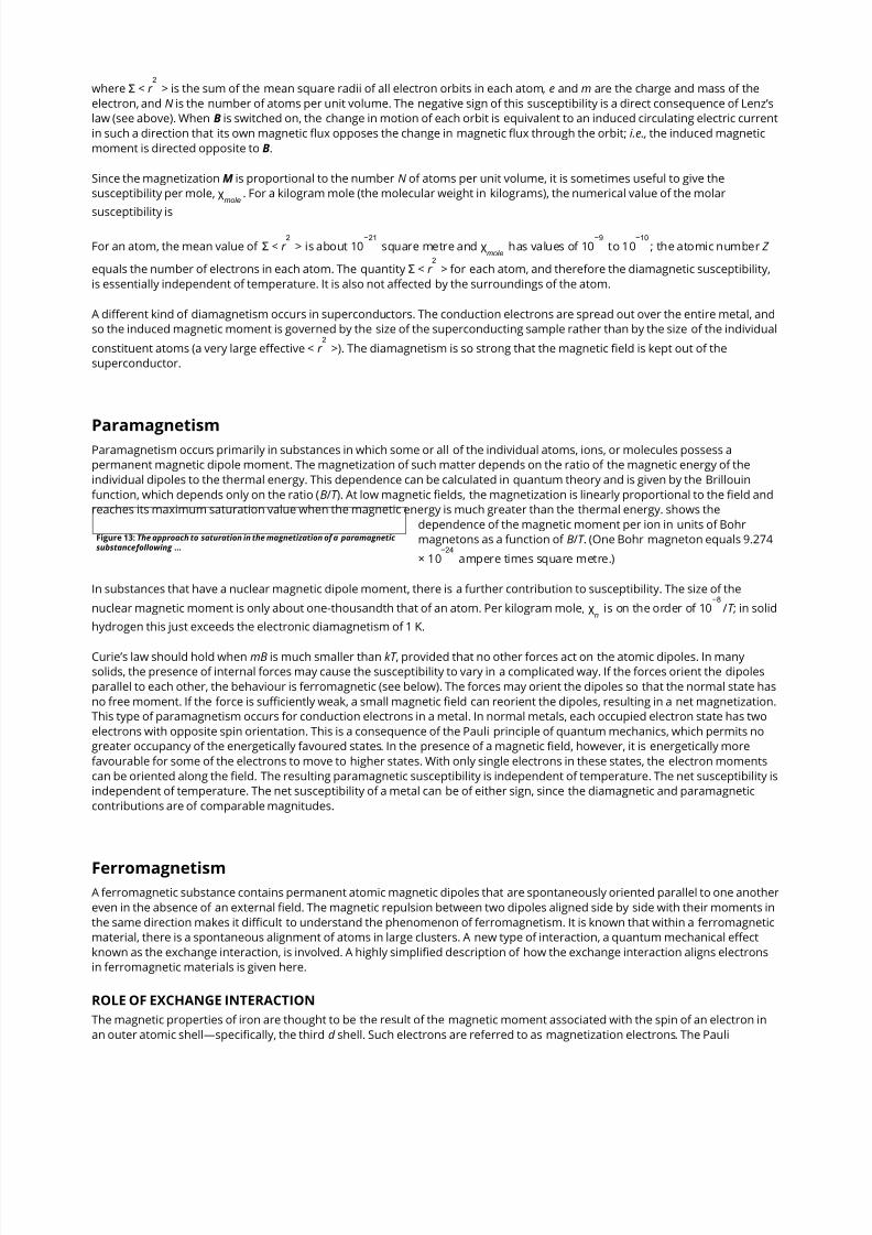
where Σ < r > is the sum of the mean square radii of all electron orbits in each atom, e and m are the charge and mass of the
electron, and N is the number of atoms per unit volume. The negative sign of this susceptibility is a direct consequence of Lenz’s
law (see above). When B is switched on, the change in motion of each orbit is equivalent to an induced circulating electric current
in such a direction that its own magnetic flux opposes the change in magnetic flux through the orbit; i.e., the induced magnetic
moment is directed opposite to B.
Since the magnetization M is proportional to the number N of atoms per unit volume, it is sometimes useful to give the
susceptibility per mole, χ . For a kilogram mole (the molecular weight in kilograms), the numerical value of the molar
susceptibility is
For an atom, the mean value of Σ < r > is about 10 square metre and χ has values of 10 to 10 ; the atomic number Z
equals the number of electrons in each atom. The quantity Σ < r > for each atom, and therefore the diamagnetic susceptibility,
is essentially independent of temperature. It is also not affected by the surroundings of the atom.
A different kind of diamagnetism occurs in superconductors. The conduction electrons are spread out over the entire metal, and
so the induced magnetic moment is governed by the size of the superconducting sample rather than by the size of the individual
constituent atoms (a very large effective < r >). The diamagnetism is so strong that the magnetic field is kept out of the
superconductor.
Paramagnetism occurs primarily in substances in which some or all of the individual atoms, ions, or molecules possess a
permanent magnetic dipole moment. The magnetization of such matter depends on the ratio of the magnetic energy of the
individual dipoles to the thermal energy. This dependence can be calculated in quantum theory and is given by the Brillouin
function, which depends only on the ratio (B/T ). At low magnetic fields, the magnetization is linearly proportional to the field and
reaches its maximum saturation value when the magnetic energy is much greater than the thermal energy. shows the
dependence of the magnetic moment per ion in units of Bohr
magnetons as a function of B/T . (One Bohr magneton equals 9.274
× 10 ampere times square metre.)
In substances that have a nuclear magnetic dipole moment, there is a further contribution to susceptibility. The size of the
nuclear magnetic moment is only about one-thousandth that of an atom. Per kilogram mole, χ is on the order of 10 /T ; in solid
hydrogen this just exceeds the electronic diamagnetism of 1 K.
Curie’s law should hold when mB is much smaller than kT , provided that no other forces act on the atomic dipoles. In many
solids, the presence of internal forces may cause the susceptibility to vary in a complicated way. If the forces orient the dipoles
parallel to each other, the behaviour is ferromagnetic (see below). The forces may orient the dipoles so that the normal state has
no free moment. If the force is sufficiently weak, a small magnetic field can reorient the dipoles, resulting in a net magnetization.
This type of paramagnetism occurs for conduction electrons in a metal. In normal metals, each occupied electron state has two
electrons with opposite spin orientation. This is a consequence of the Pauli principle of quantum mechanics, which permits no
greater occupancy of the energetically favoured states. In the presence of a magnetic field, however, it is energetically more
favourable for some of the electrons to move to higher states. With only single electrons in these states, the electron moments
can be oriented along the field. The resulting paramagnetic susceptibility is independent of temperature. The net susceptibility is
independent of temperature. The net susceptibility of a metal can be of either sign, since the diamagnetic and paramagnetic
contributions are of comparable magnitudes.
A ferromagnetic substance contains permanent atomic magnetic dipoles that are spontaneously oriented parallel to one another
even in the absence of an external field. The magnetic repulsion between two dipoles aligned side by side with their moments in
the same direction makes it difficult to understand the phenomenon of ferromagnetism. It is known that within a ferromagnetic
material, there is a spontaneous alignment of atoms in large clusters. A new type of interaction, a quantum mechanical effect
known as the exchange interaction, is involved. A highly simplified description of how the exchange interaction aligns electrons
in ferromagnetic materials is given here.
ROLE OF EXCHANGE INTERACTION
The magnetic properties of iron are thought to be the result of the magnetic moment associated with the spin of an electron in
an outer atomic shell—specifically, the third d shell. Such electrons are referred to as magnetization electrons. The Pauli
2
mole
2 −21
mole
−9 −10
2
2
Paramagnetism
−24
n
−8
Ferromagnetism
7/17/2019 Magnetism Britannica Online Encyclopedia
http://slidepdf.com/reader/full/magnetism-britannica-online-encyclopedia 9/11
Figure 14: Plot of 1/ χ . (A) Curie’s law. (B) Curie–Weiss law for aferromagnet …
Figure 15: The reduced magnetization M/M as a function of reduced
…
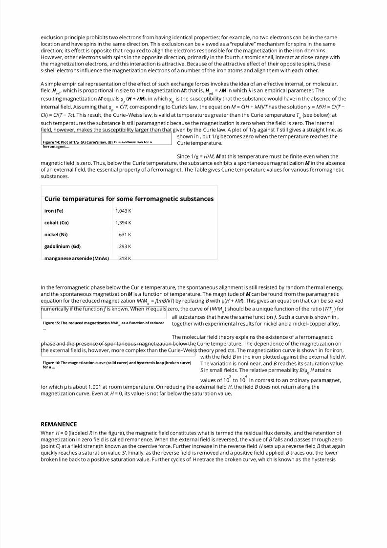
Figure 16: The magnetization curve (solid curve) and hysteresis loop (broken curve)for a …
exclusion principle prohibits two electrons from having identical properties; for example, no two electrons can be in the same
location and have spins in the same direction. This exclusion can be viewed as a “repulsive” mechanism for spins in the same
direction; its effect is opposite that required to align the electrons responsible for the magnetization in the iron domains.
However, other electrons with spins in the opposite direction, primarily in the fourth s atomic shell, interact at close range with
the magnetization electrons, and this interaction is attractive. Because of the attractive effect of their opposite spins, these
s-shell electrons influence the magnetization electrons of a number of the iron atoms and align them with each other.
A simple empirical representation of the effect of such exchange forces invokes the idea of an effective internal, or molecular,
field H , which is proportional in size to the magnetization M; that is, H = λM in which λ is an empirical parameter. The
resulting magnetization M equals χ (H + λM), in which χ is the susceptibility that the substance would have in the absence of the
internal field. Assuming that χ = C /T , corresponding to Curie’s law, the equation M = C (H + λM)/T has the solution χ = M/H = C /(T −
C λ) = C /(T − Tc ). This result, the Curie–Weiss law, is valid at temperatures greater than the Curie temperature T (see below); at
such temperatures the substance is still paramagnetic because the magnetization is zero when the field is zero. The internal
field, however, makes the susceptibility larger than that given by the Curie law. A plot of 1/χ against T still gives a straight line, as
shown in , but 1/χ becomes zero when the temperature reaches the
Curie temperature.
Since 1/χ = H/M, M at this temperature must be finite even when the
magnetic field is zero. Thus, below the Curie temperature, the substance exhibits a spontaneous magnetization M in the absence
of an external field, the essential property of a ferromagnet. The Table gives Curie temperature values for various ferromagnetic
substances.
Curie temperatures for some ferromagnetic substances
iron (Fe) 1,043 K
cobalt (Co) 1,394 K
nickel (Ni) 631 K
gadolinium (Gd) 293 K
manganese arsenide (MnAs) 318 K
In the ferromagnetic phase below the Curie temperature, the spontaneous alignment is still resisted by random thermal energy,and the spontaneous magnetization M is a function of temperature. The magnitude of M can be found from the paramagnetic
equation for the reduced magnetization M/M = f (mB/kT ) by replacing B with μ(H + λM). This gives an equation that can be solved
numerically if the function f is known. When H equals zero, the curve of (M/M ) should be a unique function of the ratio (T /T ) for
all substances that have the same function f . Such a curve is shown in ,
together with experimental results for nickel and a nickel–copper alloy.
The molecular field theory explains the existence of a ferromagnetic
phase and the presence of spontaneous magnetization below the Curie temperature. The dependence of the magnetization on
the external field is, however, more complex than the Curie–Weiss theory predicts. The magnetization curve is shown in for iron,
with the field B in the iron plotted against the external field H.
The variation is nonlinear, and B reaches its saturation value
S in small fields. The relative permeability B/μ H attains
values of 10 to 10 in contrast to an ordinary paramagnet,
for which μ is about 1.001 at room temperature. On reducing the external field H, the field B does not return along the
magnetization curve. Even at H = 0, its value is not far below the saturation value.
REMANENCE
When H = 0 (labeled R in the figure), the magnetic field constitutes what is termed the residual flux density, and the retention of
magnetization in zero field is called remanence. When the external field is reversed, the value of B falls and passes through zero
(point C ) at a f ield strength known as the coercive force. Further increase in the reverse field H sets up a reverse field B that again
quickly reaches a saturation value S ′ . Finally, as the reverse field is removed and a positive field applied, B traces out the lower
broken line back to a positive saturation value. Further cycles of H retrace the broken curve, which is known as the hysteresis
int int
p p
p
c
s
s c
s
03 4

7/17/2019 Magnetism Britannica Online Encyclopedia
http://slidepdf.com/reader/full/magnetism-britannica-online-encyclopedia 10/11
curve, because the change in B always lags behind the change in H. The hysteresis curve is not unique unless saturation is
attained in each direction; interruption and reversal of the cycle at an intermediate field strength results in a hysteresis curve of
smaller size.
To explain ferromagnetic phenomena, Weiss suggested that a ferromagnetic substance contains many small regions (called
domains), in each of which the substance is magnetized locally to saturations in some direction. In the unmagnetized state, such
directions are distributed at random or in such a way that the net magnetization of the whole sample is zero. Application of an
external field changes the direction of magnetization of part or all of the domains, setting up a net magnetization parallel to the
field. In a paramagnetic substance, atomic dipoles are oriented on a microscopic scale. In contrast, the magnetization of a
ferromagnetic substance involves the reorientation of the magnetization of the domains on a macroscopic scale; large changesoccur in the net magnetization even when very small fields are applied. Such macroscopic changes are not immediately reversed
when the size of the field is reduced or when its direction is changed. This accounts for the presence of hysteresis and for the
finite remanent magnetization.
The technological applications of ferromagnetic substances are extensive, and the size and shape of the hysteresis curve are of
great importance. A good permanent magnet must have a large spontaneous magnetization in zero field (i.e., a high retentivity)
and a high coercive force to prevent its being easily demagnetized by an external field. Both of these imply a “fat,” almost
rectangular hysteresis loop, typical of a hard magnetic material. On the other hand, ferromagnetic substances subjected to
alternating fields, as in a transformer, must have a “thin” hysteresis loop because of an energy loss per cycle that is determined
by the area enclosed by the hysteresis loop. Such substances are easily magnetized and demagnetized and are known as soft
magnetic materials.
In substances known asantiferromagnets, the mutual forces between pairs of adjacent atomic dipoles are caused by exchange
interactions, but the forces between adjacent atomic dipoles have signs opposite those in ferromagnets. As a result, adjacent
dipoles tend to line up antiparallel to each other instead of parallel. At high temperatures the material is paramagnetic, but
below a certain characteristic temperature the dipoles are aligned in an ordered and antiparallel manner. The transition
temperature T is known as the Néel temperature, after the French physicist Louis-Eugène-Félix Néel, who proposed this
explanation of the magnetic behaviour of such materials in 1936. Values of the Néel temperature for some typical
antiferromagnetic substances are given in the Table.
Néel temperature of antiferromagnetic substances
chromium 311 K
manganese fluoride 67 K
nickel fluoride 73 K
manganese oxide 116 K
ferrous oxide 198 K
The ordered antiferromagnetic state is naturally more complicated than the ordered ferromagnetic state, since there must be at
least two sets of dipoles pointing in opposite directions. With an equal number of dipoles of the same size on each set, there is
no net spontaneous magnetization on a macroscopic scale. For this reason, antiferromagnetic substances have few commercial
applications. In most insulating chemical compounds, the exchange forces between the magnetic ions are of an
antiferromagnetic nature.
Lodestone, or magnetite (Fe O ), belongs to a class of substances known as ferrites. Ferrites and some other classes of magnetic
substances discovered more recently possess many of the properties of ferromagnetic materials, including spontaneous
magnetization and remanence. Unlike the ferromagnetic metals, they have low electric conductivity, however. In alternating
Antiferromagnetism
n
Ferrimagnetism
3 4

7/17/2019 Magnetism Britannica Online Encyclopedia
http://slidepdf.com/reader/full/magnetism-britannica-online-encyclopedia 11/11
magnetic fields, this greatly reduces the energy loss resulting from eddy currents. Since these losses rise with the frequency of
the alternating field, such substances are of much importance in the electronics industry.
A notable property of ferrites and associated materials is that the bulk spontaneous magnetization, even at complete magnetic
saturation, does not correspond to the value expected if all the atomic dipoles are aligned parallel to each other. The explanation
was put forward in 1948 by Néel, who suggested that the exchange forces responsible for the spontaneous magnetization were
basically antiferromagnetic in nature and that in the ordered state they contained two (or more) sublattices spontaneously
magnetized in opposite directions. In contrast to the simple antiferromagnetic substances considered above, however, the sizes
of the magnetization on the two sublattices are unequal, giving a resultant net magnetization parallel to that of the sublattice
with the larger moment. For this phenomenon Néel coined the name ferrimagnetism, and substances that exhibit it are calledferrimagnetic materials.
Brebis Bleaney
Edwin Kashy
Sharon Bertsch McGrayne
"magnetism". Encyclopædia Britannica. Encyclopædia Britannica Online.
Encyclopædia Britannica Inc., 2015. Web. 04 Sep. 2015
<http://www.britannica.com/science/magnetism>.