MAGNETIC SENSORS SMC-SMP SERIES AND MAGNETS · PDF file86 magnetic sensors smc-smp series and...
2
86 MAGNETIC SENSORS SMC-SMP SERIES AND MAGNETS SMOOTH AND THREADED CYLINDRICAL MODELS PLASTIC AND METALLIC RECTANGULAR MODELS HIGH TEMPERATURE MODELS UPON REQUEST Dimensions mm TECHNICAL CHARACTERISTICS SMC06 NO Max switching voltage Max switching current Max switching power Max switching frequency* Contact actuation time Repeatability Temperature limits Degree of protection Housing Cable 2 metres length V A W/VA Hz ms mm °C IP mm 2 40 Ø 6 MODEL CHANGEOVER MODEL 220 0.5 10 230 2x0.14 NO NO/NC SMC06 S SMC08 NO SMC08 S SMC10 NO SMC10 S SMC12 NO SMC12 S WORKING PRINCIPLE Magnetic proximity switches are made of reed contacts whose thin plates, trap- ped in a glass bulb together with inerted gas, are easily influenced by magnetic fields that create magnetic induction, opposite polarization. Magnetic attraction force makes thin plates flex and touch each other causing an electrical contact. The plate’s surface has been treated with a special material particularly suitable for low current or high inductive circuits. Magnetic sensors compared to tradi- tional mechanical switches have the following advantage: - Contacts are well protected against dust, oxidization and corrosion thanks to the hermetic glass bulb and inerted gas; contacts are activated by means of a magnetic field rather than mechanical parts. - Special surface treatment of contacts assures in normal electrical conditions many of working cycles. - Maintenance free, reduce encumbrance. The reed magnetic switches offer many electrical and mechanical characteristics together with various output functions. - When in normally open (N.O.) mode the open reed contact closes as magnet approaches. They are supplied with two wires. - When in the normally closed position (N.C.) the Redd contact, in rest position, opens as magnet gets closer. These models are created by using exchanging reed contacts in which N.O. output has been excluded. They are supplied with two wires. - When in the exchangeable (S) mode both N.O. an N.C. functions are made available by means of a single galss bulb. Placing the magnet close to or far from the reed switch activates the two diffe- rent positions. They are supplied with three wires, one is in common, one is N.O. and one is N.C. TYPICAL REED CONTACT PROTECTIONS The lifespan of a magnetic sensor, at low values of tension and current, depends on the mechanical characteristics of the contact. Whilst at high tension and current values it’s the characteristics of the load that influences the life- span instead. In these cases it is suggestable to appliy some form of external protection at the sensors output. D C WORKING EXAMPLE D: max working distance in relation to type of magnet used C: differential stroke related to magnet removal D + C: distance during removal in which contact opens REED SENSOR MAGNET SENSOR MAGNET = C R = D R C C R MOV 150 1 20 250 3x0.14 220 0.5 10 230 2x0.25 150 1 20 250 3x0.14 220 0.5 10 230 2x0.25 150 1 20 250 3x0.25 220 0.5 10 230 2x0.25 150 1 20 250 3x0.25 2 2 2 2 ± 0.3 - 25 ÷ + 100 67 Nickelled brass M 8 x 1 40 CH 13 M 10x1 40 CH 13 M 12x1 CH 17 40 TYPICAL REED CONTACT PROTECTIONS * According to power and dimensions of the magnet together with distance between sensor and magnet. Z-TRAUQ INC. TEL. : (877) 798-7287 www.z-trauq.com [email protected]
Transcript of MAGNETIC SENSORS SMC-SMP SERIES AND MAGNETS · PDF file86 magnetic sensors smc-smp series and...
86
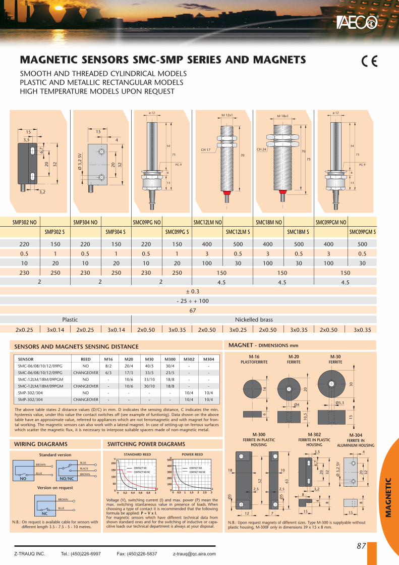
MAGNETIC SENSORS SMC-SMP SERIES AND MAGNETSSMOOTH AND THREADED CYLINDRICAL MODELSPLASTIC AND METALLIC RECTANGULAR MODELSHIGH TEMPERATURE MODELS UPON REQUEST
Dimensions mm
TECHNICAL CHARACTERISTICS
SMC06 NO
Max switching voltage
Max switching current
Max switching power
Max switching frequency*
Contact actuation time
Repeatability
Temperature limits
Degree of protection
Housing
Cable 2 metres length
V
A
W/VA
Hz
ms
mm
°C
IP
mm 2
40
Ø 6
MODEL
CHANGEOVER MODEL
220
0.5
10
230
2x0.14
NO
NO/NC SMC06 S
SMC08 NO
SMC08 S
SMC10 NO
SMC10 S
SMC12 NO
SMC12 S
WORKING PRINCIPLE
Magnetic proximity switches are made of reed contacts whose thin plates, trap-ped in a glass bulb together with inerted gas, are easily in�uenced by magnetic�elds that create magnetic induction, opposite polarization. Magnetic attractionforce makes thin plates �ex and touch each other causing an electrical contact.The plate’s surface has been treated with a special material particularly suitablefor low current or high inductive circuits. Magnetic sensors compared to tradi-tional mechanical switches have the following advantage:- Contacts are well protected against dust, oxidization and corrosion thanks tothe hermetic glass bulb and inerted gas; contacts are activated by means of amagnetic �eld rather than mechanical parts.- Special surface treatment of contacts assures in normal electrical conditionsmany of working cycles.- Maintenance free, reduce encumbrance.The reed magnetic switches o�er many electrical and mechanical characteristicstogether with various output functions.- When in normally open (N.O.) mode the open reed contact closes as magnetapproaches. They are supplied with two wires.- When in the normally closed position (N.C.) the Redd contact, in rest position,opens as magnet gets closer. These models are created by using exchangingreed contacts in which N.O. output has been excluded. They are supplied withtwo wires.
- When in the exchangeable (S) mode both N.O.an N.C. functions are made available by means ofa single galss bulb. Placing the magnet close to orfar from the reed switch activates the two di�e-rent positions. They are supplied with three wires,one is in common, one is N.O. and one is N.C.
TYPICAL REED CONTACT PROTECTIONS
The lifespan of a magnetic sensor, at low values of
tension and current, depends on the mechanical
characteristics of the contact.
Whilst at high tension and current values it’s the
characteristics of the load that in�uences the life-
span instead. In these cases it is suggestable to
appliy some form of external protection at the
sensors output.
DC
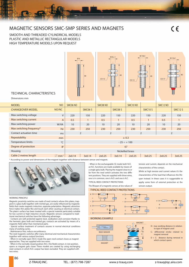
WORKING EXAMPLE
D: max working distance in relationto type of magnet used
C: di�erential stroke related tomagnet removal
D + C: distance during removal inwhich contact opens
REED SENSOR
MAGNET
SENSOR
MAGNET
=C R
= D
RC
C R
MOV
150
1
20
250
3x0.14
220
0.5
10
230
2x0.25
150
1
20
250
3x0.14
220
0.5
10
230
2x0.25
150
1
20
250
3x0.25
220
0.5
10
230
2x0.25
150
1
20
250
3x0.25
2222
± 0.3
- 25 ÷ + 100
67
Nickelled brass
M 8 x 1
40
CH 13
M 10x1
40
CH 13
M 12x1
CH 17
40
TYPICAL REED CONTACT PROTECTIONS
* According to power and dimensions of the magnet together with distance between sensor and magnet.
Z-TRAUQ INC. TEL. : (877) 798-7287 www.z-trauq.com [email protected]
87
®
MA
GN
ETIC
NC
NO NO/NC
SENSORS AND MAGNETS SENSING DISTANCE
166
83220
4
15
Ø 3
,2 S
V
3220
3,5
15
6,7
8
10,5
20
Ø4
1530
Ø5,3
712
Ø5
Ø5
52 63
2,5 2,5
18 10
3,2
4
8
MAGNET - DIMENSIONS mm
The above table states 2 distance values (D/C) in mm. D indicates the sensing distance, C indicates the min.hysteresis value, under this value the contact switches off (see example of funtionig). Data shown on the abovetable have an approximate value, referred to appliances which are not ferromagnetic and with magnet for fron-tal working. The magnetic sensors can also work with a lateral magnet. In case of setting-up on ferrous surfaceswhich scatter the magnetic flux, it is necessary to interpose suitable spacers made of non-magnetic metal.
WIRING DIAGRAMS
Standard version
Version on request
BROWN
BLUE
BLUE
BLACK
BROWN
BROWN
BLUE
V
200
150
100
50
00 0,2 0,4 0,6 0,8 1
V500
400
300
200
100
00 0,5 1 1,5 2 2,5 3
I I
SWITCHING POWER DIAGRAMS
Voltage (V), switching current (I) and max. power (P) mean themax. switching istantaneous value in presence of loads. Whenchoosing a type of contact it is recommended that the followingformula be applied: P = V x I.For magnetic sensors which have different technical data fromshown standard ones and for the switching of inductive or capa-citive loads our technical department is always at your disposal.
CONTACT NOCONTACT NO/NC
CONTACT NOCONTACT NO/NC
STANDARD REED POWER REED
M-16PLASTOFERRITE
M-20FERRITE
M-30FERRITE
M-300FERRITE IN PLASTIC
HOUSING
M-302FERRITE IN PLASTIC
HOUSING
N.B.: Upon request magnets of different sizes. Type M-300 is supplyable withoutplastic housing, M-300F only in dimensions 39 x 15 x 8 mm.
M-304FERRITE IN
ALUMINIUM HOUSING
SMP302 NO
220
0.5
10
230
2x0.25
2
3220
3,5
6,7
3,2
15
SMP302 S
150
1
20
250
3x0.14
SMP304 NO
SMP304 S
SMC09PG NO
SMC09PG S
SMC12LM NO
SMC12LM S
SMC18M NO
SMC18M S
SMC09PGM NO
SMC09PGM S
220
0.5
10
230
2x0.25
2
150
1
20
250
3x0.14
220
0.5
10
230
2x0.50
2
150
1
20
250
3x0.35
400
3
100
2x0.50
150
4.5
500
0.5
30
3x0.25
400
3
100
2x0.50
150
4.5
500
0.5
30
3x0.35
400
3
100
2x0.50
150
4.5
500
0.5
30
3x0.35
3220
4
15
Ø 3
,2 S
V
± 0.3
- 25 ÷ + 100
67
Plastic Nickelled brass
54
ø 12
73
PG 9
6
13
M 12x1
70
CH 17 70
M 18x1
75
CH 2454
ø 12
73
PG 9
6
13
SENSOR
SMC-06/08/10/12/09PG
SMC-06/08/10/12/09PG
SMC-12LM/18M/09PGM
SMC-12LM/18M/09PGM
SMP-302/304
SMP-302/304
REED
NO
CHANGEOVER
NO
CHANGEOVER
NO
CHANGEOVER
M16
8/2
6/3
-
-
-
-
M20
20/4
17/3
10/6
10/6
-
-
M30
40/5
33/5
33/10
30/10
-
-
M300
30/4
23/5
18/8
18/8
-
-
M302
-
-
-
-
10/4
10/4
M304
-
-
-
-
10/4
10/4
N.B.: On request is available cable for sensors withdifferent length 3.5 - 7.5 - 5 - 10 metres.
MAGNETIC SENSORS SMC-SMP SERIES AND MAGNETSSMOOTH AND THREADED CYLINDRICAL MODELSPLASTIC AND METALLIC RECTANGULAR MODELSHIGH TEMPERATURE MODELS UPON REQUEST
Z-TRAUQ INC. Tel.: (450)226-6997 Fax: (450)226-5837 [email protected]