Magnetic Sensors for Biomedical Applications - InTechcdn.intechopen.com/pdfs/30947.pdf · Magnetic...
28
7 Magnetic Sensors for Biomedical Applications Guillermo Rivero, Marta Multigner and Jorge Spottorno Instituto de Magnetismo Aplicado (Universidad Complutense de Madrid) Spain 1. Introduction The aim of this chapter is to give an overview of the applications of magnetic and magnetoelastic sensors and actuators in Biomedicine. Over the last century, life expectancy on our planet has experienced a remarkable increase. That is if we exclude those regions ravaged by war and those others in which the population lives, or more probably survives, under conditions that we would not tolerate. In Europe this increase has been spectacular. Average life expectancy has reached 80 years old among the male population and even more for the female population and the tendency is upward. However, this has caused important health problems, as our bodies are not usually prepared to function for such a long time without repairs and/or replacements. As a result, so-called substitution surgery is now taking up an increasing percentage of the operations performed in hospitals; such as bone prostheses for hips, knees and teeth, implants for eyes and ears and artificial sphincters and penises. Besides this, it is necessary to make periodic analyses in order to test that the levels of glucose, and cholesterol, etc. are correct. So, the application of magnetism in Biomedicine covers a wide field of devices, from sensors to determine the concentration of several elements in the blood to prostheses, both active and passive, for replacing organs or articulations. Apart from all the above, some experimental treatments also use magnetic sensors or actuators. For example, magnetic nanoparticles are used for hyperthermia treatments against tumour cells or for drug delivery. In addition, much more sophisticated and expensive treatments, like magneto encephalography techniques, use magnetic elements. In this chapter we are going to describe a small number of devices, some of which are now being researched. They are divided in two categories: magnetic sensors and magnetic actuators, according to the following scheme: Magnetic Sensors In situ measurement of the mass evolution of cell culture Test of blood coagulation Sensor system for early detection of heart valve bio prostheses failure Magnetic Actuators Magnetic endoluminal artificial urinary sphincter www.intechopen.com
Transcript of Magnetic Sensors for Biomedical Applications - InTechcdn.intechopen.com/pdfs/30947.pdf · Magnetic...

7
Magnetic Sensors for Biomedical Applications
Guillermo Rivero, Marta Multigner and Jorge Spottorno Instituto de Magnetismo Aplicado (Universidad Complutense de Madrid)
Spain
1. Introduction
The aim of this chapter is to give an overview of the applications of magnetic and magnetoelastic sensors and actuators in Biomedicine.
Over the last century, life expectancy on our planet has experienced a remarkable increase. That is if we exclude those regions ravaged by war and those others in which the population lives, or more probably survives, under conditions that we would not tolerate. In Europe this increase has been spectacular. Average life expectancy has reached 80 years old among the male population and even more for the female population and the tendency is upward. However, this has caused important health problems, as our bodies are not usually prepared to function for such a long time without repairs and/or replacements.
As a result, so-called substitution surgery is now taking up an increasing percentage of the operations performed in hospitals; such as bone prostheses for hips, knees and teeth, implants for eyes and ears and artificial sphincters and penises. Besides this, it is necessary to make periodic analyses in order to test that the levels of glucose, and cholesterol, etc. are correct. So, the application of magnetism in Biomedicine covers a wide field of devices, from sensors to determine the concentration of several elements in the blood to prostheses, both active and passive, for replacing organs or articulations.
Apart from all the above, some experimental treatments also use magnetic sensors or actuators. For example, magnetic nanoparticles are used for hyperthermia treatments against tumour cells or for drug delivery. In addition, much more sophisticated and expensive treatments, like magneto encephalography techniques, use magnetic elements.
In this chapter we are going to describe a small number of devices, some of which are now being researched. They are divided in two categories: magnetic sensors and magnetic actuators, according to the following scheme:
Magnetic Sensors In situ measurement of the mass evolution of cell culture Test of blood coagulation Sensor system for early detection of heart valve bio prostheses failure
Magnetic Actuators Magnetic endoluminal artificial urinary sphincter
www.intechopen.com

Magnetic Sensors – Principles and Applications
126
Hyperthermia HeLa cell treatment with silica-coated manganese oxide nanoparticles
In the development of these magnetic devices, as well as others not described here, there are some aspects that are common to the magnetic devices used in other very different fields as, for example, railway sensors, automotive sensors or aerospace vehicles. These may apply the basic magnetic properties or the signal acquisition and control process. Nevertheless, there are some aspects, as for instance, biocompatibility, corrosion resistance, size limitation and patient comfort, in the case of a human implant, that are specific to this application. We will try to describe them through our work in this area.
2. Magnetic sensors
Magnetic sensors are based, with very few exceptions, on the same working principle: the change of magnetic moment that takes place in a magnetic material, (normally ferromagnetic), when submitted to a magnetic field, a change of temperature or, in the case of magnetoelastic materials, to a mechanical stress, generated by the medium, in which they are immersed. The measurement of this variation makes it possible to study the changes that occur in the surroundings of the sensor.
In the case of the biomedical applications, the medium may be a fluid like, for instance, blood, the cerebrospinal fluid or a culture medium or it may be organic tissue. In any case there will be an interaction between both elements, the magnetic material and the organic medium, which is undesirable. On the one hand, the organic media may be harmed since the most widely used magnetic materials, (transition metals and their alloys), are not biocompatible, except for iron which is very biocompatible; (human organs and tissues have a great affinity for iron). On the other hand, the above mentioned organic fluids have Cl-, Ca=, Na+, K+ ions and several free organic radicals which are, in general, corrosive for magnetic materials. The solution to this problem consists in coating the magnetic material with a thin layer (100 to 200 nm) of another biocompatible material, like gold, platinum, titanium oxide, silica or alumina. The most widely used coating methods are evaporation, sputtering, electrolysis and ionic implantation. The non metallic parts of the sensor also have to be made of biocompatible polymers or ceramics such as Teflon, medical silicones, and silica.
Another aspect that has to be taken into account regarding these sensors is the transmission and monitoring of the signal. Wireless transmission, which is one option in other application fields, is a compulsory one in biosensors. This is for obvious reasons in the case of internal implants, while in the case of the external ones wireless transmission is convenient so as not to restrict the patient’s movement. Magnetic sensors and actuators offer a great advantage from the start: the magnetic field is itself a wireless transmission. The advances that have taken place in the past decades in the field of cellular phones, combined with magnetic sensors and biosensors, open the door to the final development of “telediagnosis”.
The sensors that are presented in this section are based on the magnetoelastic properties of several magnetostrictive ferromagnetic alloys (Chikazumi, 1964). As is well known, a magnetostrictive material is characterized by a change of its macroscopic dimensions when its magnetization changes, getting longer or shorter (positive or negative magnetostriction respectively) along the direction of the magnetization. In other words, the energy of the
www.intechopen.com

Magnetic Sensors for Biomedical Applications
127
magnetizing field is used not only in the magnetization process but also in elastically deforming the material. The opposite phenomenon also takes place. When the material is deformed due to an external stress, not all the mechanical work is used in deforming the material, a part of the stress is used in magnetizing the material. In the free energy of the solid, a third term has to be added to the terms of elastic and magnetic energy that is called the magnetoelastic energy term. It takes into account the energy transfer between the elastic system and the magnetic one:
F Fel () Fmg(m) Fmgel (m,)
(1)
As a consequence, in these materials the magnetic susceptibility changes with the deformation (and consequently with stress) of the material and, inversely, the elastic constant of the material changes with its magnetization (and thus the applied magnetic field). The magnetic coupling term, being the one that takes into account the energy exchange between both systems, shows a resonance phenomenon: it has a maximum for a particular frequency that depends on the magnetic and elastic properties of the material.
The materials that are most widely used are the amorphous magnetostrictive alloys, in which the absence of magnetocristalline anisotropy makes it easy to control the resonance frequency, acting on the magnetic anisotropy of the material by means of appropriate thermal treatments. The amorphous magnetic materials with positive magnetostriction constant, made by the Taylor technique (Marín & Hernando, 2004), are well known due to their availability for use in wireless sensors based on magnetoelastic resonance (Vázquez & Hernando, 1996). Some recent works show the possibility of using these materials as magnetoelastic biosensors(Shem et al., 2009; Xie et al., 2009). Other works show a detailed study of the magnetoelastic coupling phenomenon in ribbons (Hernando 1983). Recently, there has been published a development, for monitoring in situ the mass of a cell culture, based on the magnetoelastic resonance of ribbon shaped metallic glasses (Rivero et al., 2008). On the other hand, magnetic amorphous microwires coated with Pyrex have attracted much interest due to their particular properties and their simple manufacturing process based on the Taylor technique. The use of these materials can reduce the dimensions of the set-up and the Pyrex cover makes them appropriate for many applications in the medical field.
2.1 In situ measurement of the mass evolution of cell culture
Cell cultures constitute one of the most frequently used assays in biology and also one of the diagnostic methods most used in Medicine. The growing of several microorganism strains, like cells, bacteria and virus etc., under conditions in which atmosphere, temperature, humidity and nutrients are controlled have been studied.
On the other hand, the research on the treatment of tumours by hyperthermia, in the last decade, has been focused on the different behaviour of normal and tumour cells over temperature. Generally, normal cells show better temperature resistance than the tumour ones. Consequently, it is very important to determine the optimum temperature for hyperthermia treatments.
The monitoring of the progress of a cell culture is conventionally done by direct observation of the evolution that takes place on a culture plate, (the support on which the cells are
www.intechopen.com

Magnetic Sensors – Principles and Applications
128
placed), using a microscope. It is essential to have perfect control over the microenvironment in which the culture is developing to ensure that any change in the behaviour and multiplication of the cells is only ascribable to the cell behaviour in a given situation and not to poor culture conditions. For this reason, the cultures are carried out inside incubation chambers where it is possible to control factors such as humidity, pH and temperature. Among all these factors, probably the most important one is strict control of the temperature since it is a critical factor in the majority of the experiments performed with cells, particularly in mammalian ones. However when the evolution of the cells is observed using a microscope, it is necessary to extract the cells from the chamber, submitting them with what may result in undetermined damages due to changes in temperature, aside from the mechanical damages that take place in each measurement.
So a system that makes it possible to continuously quantify the mass evolution of a cellular culture “in situ”, that is, without extraction from the incubation chamber would be very useful and to our knowledge, it does not exist. This sensor would enable the cellular growth to be studied accurately under different temperatures, without the periodical mechanical damage and the cooling-heating processes produced by the extraction and movement of the culture from the chamber to the microscope where the counting of the cells is performed.
One solution is a system sensor based on the magneto-elastic resonance of ferromagnetic amorphous ribbons. Other systems based on the same principle have been developed before for detecting other biological agents (Lakshmanan et al., 2007; Wan et al., 2007)
The system consists of the following elements (Fig.1):
A culture plate that has been designed with two separate baths, each one containing an amorphous magnetoelastic ribbon with an iron based composition of area 40 x 4 mm2 and 15 microns in thickness, coated with 250 nm of TiO2 immersed in a culture medium. Only one bath is seeded with cells. So we have a continuous reference independent of temperature.
An arrangement of two coils and a permanent magnet under the plate to apply the bias and the alternating field.
A scanner impedance meter (Fig. 2), connected to the coils, which measures the coils impedance around the resonance frequency of the ribbons.
A software program developed to extract the ribbons resonance frequency from the impedance measurements.
The working of the device is as follows. Inside the culture plate designed for the device two ribbons of an amorphous magnetostrictive material with the same dimensions are placed in the compartments designed for them immersed in the culture environment. One of the ribbons acts as a reference, in order to evaluate the changes on the magnetoelastic resonance frequency due to possible changes of temperature or other factors that are not directly related to the evolution of the cell culture. So, it is immersed in one of the baths containing the culture environment but without cells. A seed of the cells, whose evolution and growth is being studied, is placed in the bath containing the other ribbon. By means of the coils system (excitation-pick up system) an electromagnetic field of frequency is applied over the whole set-up and the variations in the magnetic flux density, created by the sensor system, are collected. The designed electronic system makes it possible to change the
www.intechopen.com
Magnetic Sensors for Biomedical Applications
129
frequency of the applied electromagnetic field as well as receiving the answer of the sensor in function of the frequency.
Fig. 1. Experimental set-up to measure the mass evolution of cell culture.
To perform the measurement an electronic system is used. Its flowchart is shown in figure 2. By means of a DDS (1) (Direct Digital Synthesizer) device the values of two sinusoidal signals in quadrature, sin(t) and cos(t) are obtained. By means of (2) a fixed voltage difference is generated that is used by the D/A (Analogical/Digital) (3) and A/D (8) converters. The sinusoidal signal sin(t) generated by (1) is transformed into an analogical signal by the D/A converter. This signal is amplified by means of a power amplifier (4). The amplified signal feeds the excitation/pick up system (5) that is made up by two opposite series connected coils, which generate an alternating magnetic field that energizes the magnetostrictive ribbons (6) and that also enables answer from the magnetoelastic sensor to be picked up.
The variations in the induced voltage created in the pick up system are converted into electric current variations by the voltage/current converter (7). By means of the analogical/digital converter we can obtained the digital measurement of the electric current that flows through the exciting coils. The digital signal processor (9) permits us to extract the in phase and in quadrature components of the current measured by (8) and by (10) we obtain, for each frequency, the magnitude of the impedance of the coil system, which makes it possible to measure the resonance frequency of the coils / magnetoelastic sensor setup.
www.intechopen.com

Magnetic Sensors – Principles and Applications
130
1) Direct Digital Synthesizer; 2) Voltage reference; 3) D/A Converter; 4) Power amplifier; 5) Exciting/Pick up coils; 6) Magnetoelastic sensor; 7) Voltage/Current Converter; 8) A/D converter; 9) Digital signal processor; 10) Acquisition
Fig. 2. Flowchart of the scanning impedance meter:
When the frequency of the electromagnetic field matches the frequency of the magnetoelastic resonance of any of the ribbons, the transformation of magnetic energy into an elastic one reaches a maximum. This resonance is detected by the coil system, showing a characteristic peak in the measurement of the coil impedance. The change of the magnetic resonance frequency when the mass of a magnetostrictive material changes by m is given by (Grimes et al, 1999):
2
m
m (2)
Where is the initial resonance frequency, m is is the initial mass, m is the change of mass and is the resonance frequency variation. Thus, the resonance frequency of a magnetoelastic ribbon decreases when the mass on the ribbon increases. Before the cells are seeded, both ribbons have the same resonance frequency and only one resonance peak is detected. When the culture cells on the seeded ribbon grow, two different peaks appear, corresponding to both ribbons, as shown in figure 3. The frequency interval between the peaks determines the amount of culture mass.
Preliminary experiments have been made with a human cervical cancer cell line (HeLa) in Dulbecco’s modified Eagle medium, supplemented with 10% fetal bovine serum (FBS) and 1% (v/v) antibiotic solution. Changes in the mass culture of less than 1% have been detected.
www.intechopen.com

Magnetic Sensors for Biomedical Applications
131
Fig. 3. Evolution of the resonance of ribbons arrangement. In the initial state A, both ribbons have the same resonance frequency. The left peak increases and decreases its frequency with the amount of mass on the corresponding ribbon.
2.2 Test of blood coagulation
The Time of Prothrombine (TP), and the values that derive from it, like the International Normalized Ratio (INR), are used for determining the tendency of the blood to coagulate in the presence of possible biological disorders like hepatic failure or K vitamin deficiency. It is also used to control patients that take anticoagulation drugs like warfarina or acenocumarol to prevent coronary thrombosis processes in cardiac pathologies: atrial fibrillation, and auricular fibrillation, etc. In addition, due to the increase in life expectancy, an ever growing percentage of the population needs to replace one or more cardiac valves with a mechanical prosthesis and, in some cases, more than once. All these people must be submitted to a life-long treatment using anticoagulants. This entails a permanent risk for them. So it is not rare that the problem of controlling the appropriate level of the anticoagulation agent in the treatment of several pathologies may affect about 1 – 2 % of people in the European Community. The Food and Drugs Administration (FDA) of USA estimates that about two million people begin a treatment with warfarin every year. These patients need to be controlled periodically due to the side effects of the treatment. These controls must be done
www.intechopen.com

Magnetic Sensors – Principles and Applications
132
in hospital. Nowadays, there are some portable devices (Neel et al., 1998; Askew et al., 2010) that enable the control to be done more conveniently, but the results are not very reliable. The main causes of error are usually the influence of temperature and the amount of blood involved in the test. Other methods based on the measurement of blood viscosity (Drobrovol’skii et al., 1999) need a large amount of blood.
A sensor, based on a magnetoelastic material, can be used to determine the TP and the INR in patients under anticoagulation treatment, without the need for specialized staff or installations. The method is based on the variation in the magnetic permeability of a magnetoelastic microwire induced by the change on the blood viscosity when it coagulates. When the blood coagulates, the viscosity force applied to the immersed wire dissipates, as heat, a portion of the magnetic energy supplied by the magnetic field. Therefore the apparent magnetic permeability of the microwire decreases due to the magnetoelastic coupling. The experimental set-up compares this permeability with that of a reference wire immersed in an inalterable fluid. The absolute value of the measured signal tends to a maximum when the blood coagulates. The time to raise this maximum enables the TP and the INR to be calculated.
The sensor consists of two identical microwires, with an iron base, that are placed into two capillaries with tenths of mm. inner diameter and around 5 cm in length. These capillaries are surrounded by one coil each, which are fed by two power amplifiers driven by a signal generator. The capillaries are filled with blood and with a fluid of reference, respectively. The difference between both signals increases when the blood coagulation process begins and its absolute value tends to a maximum when the blood is fully clotted. The scheme of the experimental set-up used to measure the blood coagulation is illustrated in figure 4.
Fig. 4. Scheme of the experimental setup used to measure the blood coagulation.
The sensor system consists of the following components (see figure):
www.intechopen.com

Magnetic Sensors for Biomedical Applications
133
A signal generator that provides a sinusoidal voltage signal in a range of 10 – 50 KHz. (1)
Two power amplifiers, driven by the signal of the generator, which feed two equal coils with the microwire arrangements. The gain of amplifiers can be adjusted to obtain zero signal before the test. (2)
Coil with reference arrangement (capillary + microwire + fluid of reference) (3) Coil with measurement arrangement (capillary + microwire + blood) (4) Two precision rectifiers (5) Two non-inductive resistors (6) A differential amplifier that gives the difference between the rectified voltages in the
non-inductive resistors. (7) A temperature controlled chamber in which the sensor system is introduced to perform
the test at constant temperature of 25 ºC. A temperature sensor (8) that measures the temperature in the temperature controlled
chamber. The signal of the temperature sensor is sent to a temperature controller device (9) that keeps the chamber temperature at 25 ºC.
Tests with blood samples that coagulate at different rates are illustrated in figure 5.
Fig. 5. Study of the influence in the coagulation of blood with different amounts of coagulant agent. The amount of blood is 200 l, and was mixed with 5l of coagulant (curve A), 1l of coagulant (curve B), and without coagulant (curve C).
It can be observed that blood, in the presence of the greatest quantity of coagulant agent, coagulates in a time 10 times faster than the blood without the coagulant agent. The output potential, VOUT,
of the differential amplifier shown in figure 4 is the difference between VREF
(Voltage difference in the circuit of the reference coils) and VBLOOD (Voltage difference in the
www.intechopen.com

Magnetic Sensors – Principles and Applications
134
circuit we are measuring the blood in). Both are RL circuits and the inductance L and resistance RL:
L 0
N 2
lSC W SW RL 2N SCCu SCu
(3)
Being W the relative permeability of the microwire, μ0 the permeability of free space, N the number of turns, l the length of the coil, Cu the copper conductivity and SC and SW the sections of the coil and the microwire, respectively.
Since in this setup, when R0 and RL << w L then:
VS V0 eit V V0
R0Le
i t 2
(4)
Once they are rectified, the voltage differences are:
VREF V0
R0 2
LREF
and VBLOOD V0
R0 2
LBLOOD (5)
Where LREF and LBLOOD are the inductances of the reference and measurement coils, respectively. Thus the output of the differential amplifier (see figure 1):
VOUT VREF VBLOOD V0
R0 2
1
LREF
1
LBLOOD
(6)
This output is taken to zero at the initial moment, adjusting the gain of the feeding amplifiers. From this moment, the permeability, W, of the microwire immersed in blood begins to decrease because of the effect of the viscosity force the blood exerts on it while it clots. This makes LBLOOD decrease as well.
The output of the differential amplifier depends on time as follows:
VOUT (t) V0
R0 2
1
LBLOOD (0) 1
LBLOOD (t)
V0 R0 2
LBLOOD (0)1 SC SW W (0)
SC SW W (t)
(7)
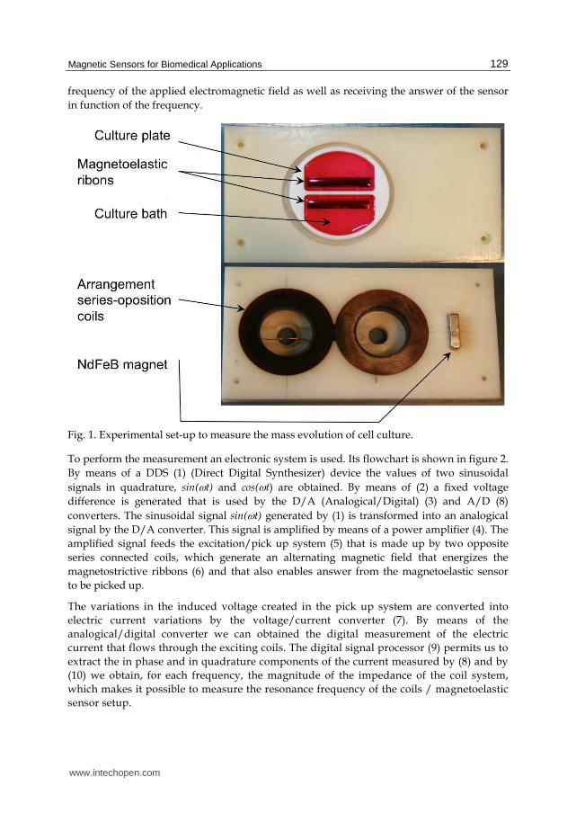
Figure 6 shows the curve obtained from human blood without coagulant agent and the theoretical VOUT(t) curve, following the equation (7). In this expression the best adjustment to experimental results is obtained assuming a relative permeability change of the microwire during the coagulation process as:
2
, ,0 , 2( ) exp
W W W W
tt (8)
Being W,0 and W, the measured values of the initial permeability and the permeability when the blood is completely coagulated, respectively, and a time constant that depends on the coagulation properties of the blood sample. The value of for the best adjustment to the experimental values enables the TP and INR to be determined.
www.intechopen.com
Magnetic Sensors for Biomedical Applications
135
0 20 40 60 80-0,014
-0,012
-0,010
-0,008
-0,006
-0,004
-0,002
0,000
0,002
Time (min)
Vout
Experimental
Vout
TheoreticalV
OU
T(V
)
Fig. 6. The points with a green circle represent the experimental data of the coagulation of blood without coagulant. The line in red represents the proposed approximation adjusted to the experiment.
2.3 Sensor system for early detection of heart valve bioprostheses failure
Heart valves are widely used in cardiac diseases. For example in 2002 in Spain 9269 heart valves were implanted as against 310 heart transplants. There are two kinds of heart valves, mechanical and biological ones. Biological heart valves, currently made with calf pericardium, have a similar shape to that of the original ones and better hemodynamic conditions than the mechanical ones. Moreover they have the advantage that the patient does not need lifelong treatment with anticoagulants, as happens with the mechanical valves. On the other hand, biological cardiac valves, or bioprostheses, have the inconvenience of their limited durability (about 10 years on average). What is more troublesome is the fact that they have an important dispersion that may be estimated in plus/minus 3 years (Kouchoukos et al, 2003).
These bioprostheses fail for several reasons, similar to those of the original ones and there are many factors that may contribute to their deterioration. The most important are biochemical degradation and mechanical damage of the tissue. Mechanical fatigue is the result of the great number of opening and closing cycles (approximately 30 million per year), which the valve is submitted to. Their effects are cumulative, and are expressed by lineal ruptures and/or perforations.
This means that it is difficult to determine the best moment for replacing the valve. The problem of the user getting it done too late must be balanced against the economic costs to the Social Security system, if is carried out unnecessarily early. So, a sensor is needed that
www.intechopen.com

Magnetic Sensors – Principles and Applications
136
can continuously monitor the working of the valve and give physicians objective data in order for them to make the substitution of the valve at the right time. This sensor has to be non-invasive and biocompatible. If small samples of soft magnetic material are inserted in the valve their movement can be detected when the valve is submitted to an alternating field of a frequency ranging from a few tens of Hz to tens of MHz, depending on the magnetic material used and its morphology (fig 7).
The material inside the body cannot interfere with the normal working of the valve. Each element’s mass should not be higher than a few micrograms and its section must be of 10-8 m2 or lower. Different soft magnetic materials meet these requirements as for example amorphous ribbons and wires made by melt spinning or amorphous microwires made by rapid quenching.
Fig. 7. Detection of motion of bioprostheses cusps with microwires inserted.
The best results are obtained by using an amorphous Co-based microwire as a magnetic element. This microwire has a diameter of 20 m and is coated in the manufacturing process itself by a glass layer. The total diameter of the coated microwire is 45 m. It presents remarkable advantages over other materials (Marin P. & Hernando A. 2004):
It can be integrated in the cusps without the usage of biological glues. Due to its minimum size it neither diminishes the cusps flexibility, nor does it change
their mass in an appreciable way. It is coated, during the process of manufacture, by a biocompatible glass, so facilitating
its integration. Despite its reduced size the magnetic signal obtained is comparable to that obtained
with the other models. Its high-shape anisotropy (10mm×45m) together with its high-magnetic susceptibility
makes it possibly to greatly reduce the energy expense needed for the sensor working.
www.intechopen.com
Magnetic Sensors for Biomedical Applications
137
The sensor works as follows. An excitation field is generated by an external coil. This field magnetizes the soft materials attached to the cusps and this magnetization triggers to a signal, the carrier signal, having the same frequency as that of the excitation one (2 kHz). The working of the valve causes a movement of the magnetic elements together with the cusps, producing a change in their position with respect to the exciting and detection coils (fig 7). This change in the relative position causes a modulation in the carrier signal (2 kHz) that clearly has the frequency of the opening and closing of the valve (cardiac rhythm, 60–80 cycles/min).
The dysfunctions produced in the movement of the cusps during the opening and closing of the valve, due to degradation, hardening or rupture processes, provoke a change in the modulated signal, which is monitored against the signal obtained in the standard working conditions. The comparison between both signals may allow the medical services to establish precisely the moment when the valve must be replaced (Rivero at al., 2007). All this may be done by wireless, without any need to implant, in the patient, any electrical or electronic device for detection or transmission, or to establish any type of material joint with the valve to the patient.
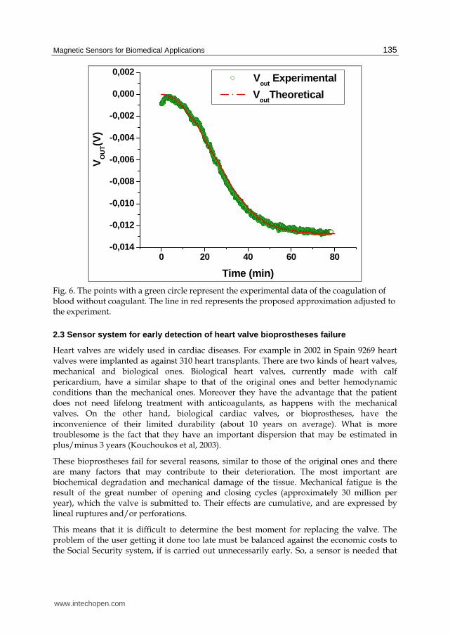
This sensor has been tested in a hydrodynamic setup. Figure 8 shows the signal that is received in the pickup coils. Three different series of images corresponding to the opening process of the valve with different damage levels can be seen. The electrical signal obtained by the sensor system is superimposed on the corresponding image. The first row (a) corresponds to the opening process of the undamaged valve. The second row (b) corresponds to the valve with a slightly glued commissure, and the third row (c) corresponds to the same valve but with the three commissures slightly glued. In the last case it can be seen that there is a dramatic change in the electrical signal, as well as in the movement of the cusps.
Fig. 8. Opening process of the valve with different damage levels.
3. Magnetic actuators
The working of most conventional electromagnetic actuators is based on the force exerted by a magnetic field on a moving element, made of a ferromagnetic element, that eventually can
www.intechopen.com

Magnetic Sensors – Principles and Applications
138
become a permanent magnet. The magnetic field that acts on the material can be created by a coil, with the appropriate feeding (with alternate or direct current) or by a permanent magnet. This force is used to change the moving element.
Other kind of magnetic actuators are based on the change in dimensions or the deformation that takes place in a magnetostrictive magnetic material (see section 2) when there exists a variation of the magnetic field that is acting on it. As in the previous case this field can be originated by a coil or a permanent magnet when it changes its position or its orientation. This kind of actuators, based on the effect commentated in section 2 of this chapter, present great advantages for their application on biomedicine since their magnetic field is not shielded by human body tissues due to their low conductivity. In other words the actuator field can be established by devices placed outside the human body although the actuator element is an internal implant. The limits imposed by the size and biocompatibility requirements are the same as the ones described in section 2 for the magnetic sensors.
There are other kinds of recent applications of magnetic actuators related to temperature. A general property of magnetic materials, except the ferrites, is an electrical conductivity in the range of metal and metal alloys, ranging between 104 and 107 S/m. This means that if the actuator field is an alternating one with a frequency , eddy currents will be induced in the element that will dissipate a Joule power proportional to the conductivity value, the square of the magnetic field amplitude and the square of the frequency.
2 2
0 JouleW B (9)
Moreover, any ferromagnetic material will dissipate, through heat, the power needed for the magnetization process, which will be proportional to the frequency.
Hyst
hystloop
W HdB (10)
If the frequency is high, (between 10 KHz and 103 KHz), the power dissipated through both causes may mean a significant local increase in the medium temperature. This behavior has been used by numerous researchers in the past decade in order to try to find a treatment against tumors (hyperthermia) which would be not too aggressive for the patient. In order to avoid the danger of creating an embolism in narrow capillaries, nanoparticles with diameters ranging from five to a few hundreds of nanometers are used. To avoid the particles aggregating because of the attraction of their magnetic moment, superparamagnetic materials or ferromagnetic materials functionalized with polar radicals that cause electrostatic repulsion are used. Another application of these particles, (in their hollow mode), is to use them as a vehicle for transporting medicines to the place in the organism where they have to act. Once they are there they are heated with a high frequency magnetic field that provokes their fragmentation and frees the medicine inside the nanoparticle.
These magnetic actuators have given rise to a new kind of materials, using traditional materials as a starting point but reducing them to smaller and smaller sizes. One only has to consider that in a gold cube with a 1 micron side just one part in a million of their atoms are arranged on the surface while in a cube of 2 nm 60 % of them are on the surface. So it is not strange that their physical properties become very different from that of bulk gold when
www.intechopen.com

Magnetic Sensors for Biomedical Applications
139
reaching the limit where gold nanoparticles of diameter 1.5 nm demonstrate a spontaneous magnetic moment (Crespo et al., 2004).
3.1 Magnetic endoluminal artificial urinary sphincter
Urinary incontinence is not considered an illness but a symptom and is only treated when it becomes a social problem. Urinary incontinence is defined by the complaint of any involuntary leakage of urine (Abrams et al., 2002) or unintentional loss of urine that occurs with such frequency and in such quantities as to cause physical and/or emotional distress in the person experiencing it. Moreover, the number of people suffering from this is estimated to be around a million people among the adult population in western countries (Irwin et al., 2006).
Depending on the origin and the severity of the affection, it is treated with absorbent pads, pharmacological or surgical methods. For more than 30 years physicians have implanted inflatable artificial sphincters that simulate the sphincter function and permit the voluntary control of the micturition (American Medical System). However this device requires highly invasive surgery since it is necessary to implant a cuff around the urethra, in addition to a balloon, that regulates the cuff pressure and a bulb that controls the inflation and deflation of the cuff.
The objective of developing a magnetic artificial urinary sphincter is to look for a minimally invasive device that permits voluntary micturition control, making use of the potential of the magnetic field to exert a force without physical contact.
The preliminary specifications for the device are the following:
Voluntary opening by the patient Automatic closing Automatic opening when the safety pressure is reached External magnetic drive, without other devices Urethral implantation without surgery Immunity to RF fields
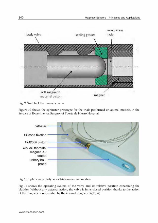
The device consists of a magnetic valve placed in the urethra. The urine is evacuated by bringing a permanent magnet near the body of the patient. The magnetic valve consists on (Figure 9) a hollow cylindrical body valve with a toroidal magnet fixed at one of their ends and a soft magnetic material piston that is attracted by the magnet, closing the evacuation hole. As a sealing gasket a medical grade silicone O-ring is used.
If a more powerful external magnet is brought near the valve, the magnetization of the piston (made of a soft magnetic material) is reversed and a repulsion force between the internal magnet and the piston appears, causing the evacuation hole to open. When the external magnet is moved away, the interaction between the internal magnet and the piston turns attractive again and the valve closes automatically. Furthermore, the system is provided with a safety system preventing overpressure in the bladder. By adjusting the distance between the piston and the internal magnet, a pressure level can be fixed in such a way that if the pressure inside the bladder reaches that value, then the valve opens automatically.
www.intechopen.com
Magnetic Sensors – Principles and Applications
140
Fig. 9. Sketch of the magnetic valve.
Figure 10 shows the sphincter prototype for the trials performed on animal models, in the Service of Experimental Surgery of Puerta de Hierro Hospital.
Fig. 10. Sphincter prototype for trials on animal models.
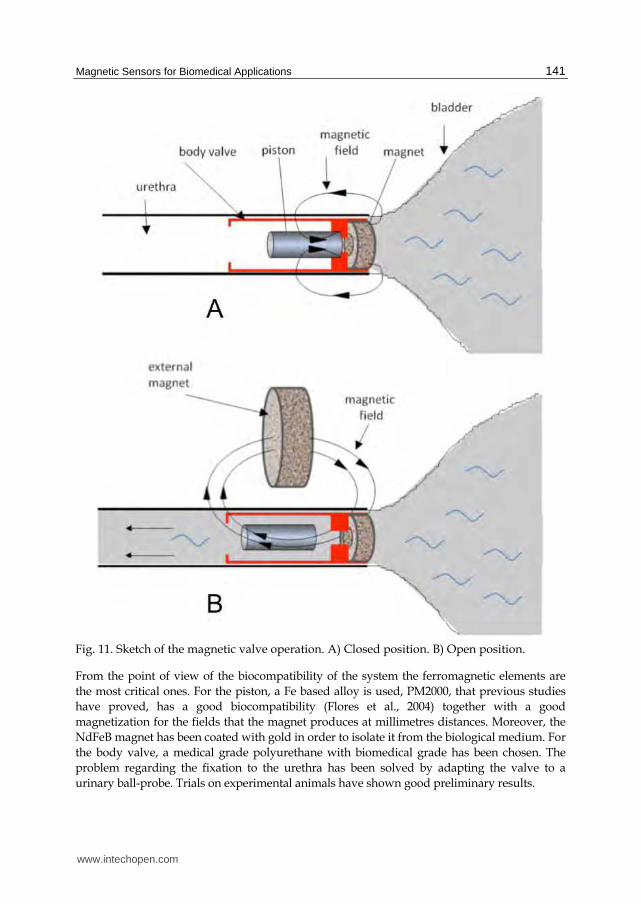
Fig 11 shows the operating system of the valve and its relative position concerning the bladder. Without any external action, the valve is in its closed position thanks to the action of the magnetic force exerted by the internal magnet (Fig11, A).
www.intechopen.com
Magnetic Sensors for Biomedical Applications
141
Fig. 11. Sketch of the magnetic valve operation. A) Closed position. B) Open position.
From the point of view of the biocompatibility of the system the ferromagnetic elements are the most critical ones. For the piston, a Fe based alloy is used, PM2000, that previous studies have proved, has a good biocompatibility (Flores et al., 2004) together with a good magnetization for the fields that the magnet produces at millimetres distances. Moreover, the NdFeB magnet has been coated with gold in order to isolate it from the biological medium. For the body valve, a medical grade polyurethane with biomedical grade has been chosen. The problem regarding the fixation to the urethra has been solved by adapting the valve to a urinary ball-probe. Trials on experimental animals have shown good preliminary results.
www.intechopen.com

Magnetic Sensors – Principles and Applications
142
3.2 Hyperthermia HeLa cell treatment with silica-coated manganese oxide nanoparticles
The treatment of tumours by hyperthermia is based on the killing of tumour cells by heating them. Temperatures over around 42ºC kill tumour cells. Moreover, the behaviour of normal and tumour cells is different with temperature; generally, normal cells show better resistance to temperature than the tumour ones (Hahn et al., 1974). If it is possible to heat the tumour area at temperatures that would kill tumour cells but not the normal cells, we would be able to treat tumours selectively with less damage to the body than other therapies such as chemotherapy.
As mentioned above, in the past years nanoparticles have attracted much attention for medical applications due to their small size that enables them to be inserted inside the body and transported round it. In particular, magnetic nanoparticles have been used as a heating source for magnetic hyperthermia. Under the influence of an alternating high-frequency magnetic field, they generate heat through hysteresis losses, induced eddy currents and Neel and/or Brown relaxation processes (Jordan et al., 1993). Thus, different kinds of magnetic nanoparticles have been tested as a heating source. The new materials must satisfy stringent conditions: they must be biocompatible, be stable in aqueous solution, possess high thermal efficiency as heating elements and be highly accumulating inside tumour cells, so that when applying the alternating magnetic field (AMF) the increase in temperature can induce cellular death (Kong et al., 2001). Superparamagnetic iron oxide is the most common material tested up to now due to its high biocompatibility, low synthesis cost, enhanced specific loss power and easy functionalization (Hergt et al., 1998). However, in spite of these advantages, it is not possible to control the local heating temperature, because it is not possible to measure the exact temperature or distribution of temperature in a tissue under magnetic particle hyperthermia (MPH) treatment. Therefore, the temperature reached in a tissue under MPH treatment will depend on a large number of particle parameters, such as size and concentration in the tissue of the nanoparticles, the conditions of the external applied field, and the length of the treatment (Gazeau et al., 2008).
To avoid the obstacle of temperature control, new materials of tunable Curie temperature (Tc) are being intensively investigated to achieve temperature autostabilization at the hyperthermia conditions (Pradhan et al., 2007). Magnetic particles with tuneable Tc will prevent the temperature of the whole tumour or the hottest spot around the particle raising its temperature over the Curie Temperature, so, avoiding the use of any local temperature control system.
When a ferromagnetic nanoparticle reaches its Curie Temperature it becomes paramagnetic, and its magnetic moment drastically decreases. Thus, the eddy currents and the relaxation processes decrease as well and the hysteresis losses disappear. This means that the nanoparticles will stop heating the medium and the temperature will go back below the Curie Temperature becoming ferromagnetic again and so recovering the heating process. Therefore, it becomes a self regulating system and the culture temperature will always be around the Curie Temperature.
Bearing in mind all these facts, manganese perovskites meet the requirements for magnetic hyperthermia treatments.
www.intechopen.com

Magnetic Sensors for Biomedical Applications
143
The manganese oxides perovskite La1-x(SrCa)xMnO3 have a Curie temperature that, depending on the cation ratio, can range from 300 K to 350 K (so 42-44 ºC is within the range) and they have large magnetization values of about 30 – 35 emu/g.
The preparation of the particles is as follows. First the particles are created by the ceramic method from compounds of La2O3, CaCO3, SrCO3, and MnO2. These particles obtained by the ball milling method form agglomerates due to the dipolar magnetic interaction and the lack of surfactants. The agglomerates also have a large size distribution, with sizes greater than 1 m. Since the magnetic interaction decreases with temperature, the particles are dispersed in ethanol and heated over the Tc in order to disaggregate them and to select the smaller ones, thus obtaining an average size of 100 nm. These NPs are not biocompatible so they have to be coated with silica following the Stöber method (Stöber et al., 1968).
The magnetic properties are not significantly affected by the size selection. Since the size is around 100 nm, the selected NPs still behave quite like the as-prepared ceramic. However, the magnetic properties are affected by the coating: the total magnetization is reduced by the presence of diamagnetic silica and the Curie Temperature decreases when the nanoparticles are coated. For example, for the composition La0.56(CaSr)0.22MnO3, at low temperature the magnetization at 1 kOe decreases from 31 to 21 emu/g (about 32%) while the Tc decreases from 68 ºC to 44 ºC for the uncoated and the coated nanoparticles respectively.
Another problem that must be faced is if it is necessary to increase the temperature up to 42 – 44 ºC in the whole tumour (so needing magnetic nanoparticles with very high magnetic moment or a very high concentration of nanoparticles) (Lacroix et al., 2009) in order to induce tumour damage or if it is enough to raise the temperature locally in the cells to induce apoptotic tumour death. The study of intracellular hyperthermia can shed light on this question.
Biological tests with perovskites were performed in order to prove their validity as a heating source for tumour hyperthermia. They were put inside a culture of HeLa cells. HeLa cells are a family of tumour cells widely used by biologists. HeLa cells were incubated with a concentration of 0.5 mg/ml of perovskites for 3 h. After incubation, cells were washed 3 times with PBS and then exposed for 30 min to a 100 KHz alternating magnetic field of 15 mT.
The cells incubated with the perovskites but without being submitted to an alternating magnetic field do not show any change, thus, demonstrating that the coating of the nanoparticles makes them biocompatible as expected. For the cells submitted to an alternating field the cell morphology was not affected immediately after the incubation and exposition to AMF. However, the perovskite + AMF treatment provoked deep morphological alterations, 24 h after the combined treatment, which corresponds to different stages of cell death by an apoptotic process. It is known that apoptosis is a regulated process which requires the active participation of specific molecules and is a characteristic mechanism of cell death for temperature around 42 ºC. The temperature increase of the culture during the application of the AMF (controlled by an infrared thermometer) was lower than 0.5 K for the PER incubated HeLa cells. This means that the small size of the perovskites cannot heat the cell culture. However, perovskites can induce local hot spots that damage irreversibly the structure and functionality of the cell proteins triggering the cell apoptosis (Fig 12).
www.intechopen.com

Magnetic Sensors – Principles and Applications
144
Fig. 12. Nanoparticles (black spots) inside the cell after apopthosis (White holes) (Villanueva, 2010)
These results show that perovskite nanoparticles have a high potential for cancer cell hyperthermia, working as smart mediators for self controlled heating of tumours, where the heating source is switched off when the local temperature of the tumour reaches the desired value.
4. Biocompatibility
In the previous paragraphs it has been shown that the different materials that are used as sensors should meet different requirements from the point of view of their magnetic properties: the optimal response of the device could be achieved with the softest, the hardest or the most magnetostrictive material. It depends on the application. It should be remarked that to assure a long-term working life-time of the device, it is necessary to look for a material with specific mechanical properties (González-Carrasco, 2009), as for example high fatigue resistance for the cardiac valve sensor. In the particular case of the implantable devices, it is evident that there is a decisive requirement that is more important than all those physical properties. This is, that the device cannot harm the patient, so the system must be biocompatible. The definition of the term Biocompatibility says: “Biocompatibility refers to the ability of a material to perform with an appropriate host response in a specific situation” (Williams, 1987).
Bearing in mind, that the human organism can be considered, in a very schematic way, as an assemblage of different tissues and fluids with different properties (biological, physical and chemical) as well as being a very aggressive medium against exogenous elements, it is easy to infer that the problem of the biocompatibility of the materials is very complex and should be studied for each specific application (Williams, 2008). In general, biocompatibility studies usually begin with in vitro tests (i.e. cell viability, preferably with cells of the host tissue/organ, and an endless quantity of trials concerned with the promotion or inhibition of biological process) followed by in vivo trials on experimental animals (Ratner et al., 2004).
Biomaterials, understood as materials that are biocompatible, can be classified in accordance with different parameters, for example their nature (metal, ceramic, polymer...), their application (bone, vascular, eye...) or their size. For reviewing the state of the
www.intechopen.com

Magnetic Sensors for Biomedical Applications
145
biocompatibility of magnetic materials, this last option is more appropriate. Two large groups of materials can be distinguished: those used as bulk materials and the micro/nanoparticles.
On the one hand, among the widely established bulk biomaterials (titanium alloys, cobalt-chromium alloys, noble metals, Nitinol, austenitic stainless steel, alumina, calcium phosphates, carbon and polymers like UHMW polyethylene, PMMA or silicones) there are none with ferromagnetic properties. Regarding the metallic materials (excepting the noble metals, which are not ferromagnetic) only those that develop a well attached surface oxide layer usually present a good response to corrosion. In fact, if Chromium is added above 12% weight to Fe or Co the alloys become stainless. The stainless steels used for medical applications (316L and 304L) also incorporate Ni, among other elements, in their composition, which improves their corrosion resistance and stabilizes the face centred cubic structure. This latter fact explains their paramagnetic character.
In general, it could be said that most the ferromagnetic materials are not biocompatible or their biocompatibility is not known. Very few papers on the biocompatibility of magnetic materials can be found. Even fewer can be found on cells. Most of them are corrosion studies done with liquids that simulate the pH of different biological mediums. Magnets have attracted interest in medicine (Riley at al., 2002). In particular, rare earth magnets have been investigated in the field of dentistry to push or pull teeth or as prostheses retention systems (Noar et al., 1999). They show bad corrosion resistance and have been used embedded in different polymeric materials or with Ti coating.
Studies on Fe-Co alloys and magnetostrictive NiMnGa and Terfenol_D show poor cell viability, excepting the last one that presents high corrosion (Pouponneau et al. 2006). However the system Co-Pt and Fe-Pt show better corrosion response (Yiu et al. 2004)). At research level, the Fe based alloy PM2000 shows good corrosion behaviour and cell viability together with a significant saturation magnetization, especially when coated with alumina by thermal oxidation (Flores et al., 2004).
The surface is where the first contact between the material and the biological entity takes place. This is why surface biomaterials are being researched in depth, while surface modification is one of the most widely used strategies for improving biomaterial properties.
In the case where a magnetic feature can only be achieved with a material that is not biocompatible the simplest solution is to encapsulate it or to coat it with a biocompatible material. Anyway, as coatings also present their own problems (adherence, thickness,...), it would be very interesting to investigate and to develop biomaterials with good magnetic properties.
On the other hand, there already exist some nanoparticles commercially used as contrast agents in imaging diagnostic techniques or drug targeting and magnetic separation applications, like the Iron Oxide or the Gd, because of their magnetic properties. However, an enormous effort is being made to develop biocompatible magnetic nanoparticles for their application in biomedicine due to the attractive possibilities that they offer (Pankhurst, 2003) as hyperthermia agents for coadyuvant cancer treatment, drug delivery systems, as well as for the previously mentioned reasons.
www.intechopen.com

Magnetic Sensors – Principles and Applications
146
The problem of the toxicity of nanoparticles goes further than in vitro trials with cells, (it can be really complex) (Lewinsky, 2008). In fact this kind of material has other problems when used for long term devices. For example, once their behaviour with cells has been tested, it is essential to understand their survival in the body. Do the macrophages detect them too soon or on the contrary, do the nanoparticles tend to accumulate in some important organ such as the liver or brain? (Hoet et al., 2004). Nanoparticles are frequently coated with different organic or inorganic materials (as dextran (Lacava, 2001) or silica (Villanueva, 2010)). Sometimes this is done to make them biocompatible, sometimes to obtain an appropriate dispersion and sometimes to functionalize them.
5. Further research
Magnetic sensors can be applied in several fields of Biology and Medicine. Practically all the devices mentioned in this chapter are still in the optimization phase or in clinical trials. So, the related research is still ongoing.
The hyperthermia treatment studies for malignant tumors merit, because of their enormous interest, to be discussed separately. This is research with a marked interdisciplinary character, since it presents challenges that specifically concern doctors, biologist, chemists, material´s engineers and, of course, physicists. Although nowadays, nanoparticles have been achieved that seem to work very well, there remain problems that are far from being solved.
To determine if the origin of the damage produced to the tumor cells comes from the temperature increase or from the movement of the particles inside the cells themselves.
To concentrate the particles in the nearby tumor area and avoiding most of them being eliminated by the reticulum-endothelial along the path to the tumor.
To control the temperature treatment inside a medium that the circulatory system keeps constantly at 37oC.
To eliminate the particles from the patient´s body after the treatment and avoiding their concentration in organs, such as the kidneys, liver, spleen, etc.
To concentrate the high frequency magnetic field in the tumor area, in order to avoid heating the particles that have been absorbed by other organs or tissues.
Last but not least, to manufacture cheap nanoparticles so that if the treatment works, everybody can have access to it.
Another area of research we are interested in is the application of magnetic sensors and actuators in remote monitoring of multiple sclerosis patients. Multiple sclerosis (MS) is a chronic, degenerative disease that affects young people and which , according to the last survival studies, not only shortens life approximately by 10 years but also produces important limitations and deficiencies affecting the wellbeing of the patient, over the course of its development.
During its progress, MS patients present a very varied symptomatology. So, in the first stages of the disease it is usually asymthomatic and without objective neurological deficiencies. It is only during the 5 first years that objective neurological manifestations begin to appear. As a general rule, after between 10 to 15 years of development, the deficiencies are very evident and begin to have clear repercussions on the physical and cognitive activities of the patients. Between the 15th and 20th years of development, the
www.intechopen.com

Magnetic Sensors for Biomedical Applications
147
limitations increase by up to 33%, which means severe restrictions on mobility. In these advanced stages of the disease, the symptoms limit the patient’s mobility very severely and drastically affect the quality of life and autonomy of these patients.
The goal of this research would be to exploit the possibilities offered by telemedicine and remote control for improving the assistance, monitoring and quality of life in MS patients, in the advanced stages and with very limited mobility.
It would be focused on three aspects:
Symptoms monitoring: Spasticity Dysphagia Pain Autonomic alteration: cardiac rhythm, blood-pressure variations, gastrointestinal
mobility alterations and sphincters control (anal and urethral) Position Sleep quality
Development of complications derived from the physical condition Decubitus ulcers Urine infection Respiratory infection (aspiration) Position alteration (orthopaedic malformation)
Clinical evolution monitoring ( search of image subrogated markers obtained by periodical and quantifiable Magnetic Resonance studies) Walk monitoring Upper limbs monitoring Mental function monitoring Autonomic state monitoring
These neurological requirements scenarios could be analyzed at a distance by using the appropriate sensors (with calls and alerts), so that the neurologist would be able to treat the patient without the patient needing to be in presence of the physician and so avoiding complications that would decrease the quality of life.
6. Conclusion
It is not possible in the space available to offer an exhaustive overview of the applications of magnetic sensors in the field of medicine. We have limited ourselves to presenting just some particular works, that we have recently developed, some that are currently being developed and some that are still in the future.
It seems obvious that the development of magnetic sensors and actuators is generally linked to the development of magnetic materials. Furthermore, it could be said that the development of our technological civilization is linked to the development of magnetic materials. If this assertion sounds too exaggerated, please imagine the consequences of the disappearance of the silicon steel sheet and with it all the electric motors and transformers. Or just think about the permanent magnets inside all mobile phones, or the magnetic
www.intechopen.com

Magnetic Sensors – Principles and Applications
148
information storage medium. Or, going back in time, at what stage of development would we be without the great discoveries made possible by the compass.
This is even more evident in the case of the biomedical applications. The increasingly strict requirements for sensors and actuators in the field of safety, as well as for biocompatibility, corrosion, miniaturization, low consumption, etc. are impossible to meet without new magnetic materials. Just think that the fight against the most feared disease of our time could depend on something so simple (but not easy) as the suitable magnetic material.
7. Acknowledgment
The authors wish to acknowledge the grants provided by Ministerio de Educación of Spain, Comunidad de Madrid, Ministerio de Sanidad of Spain, Laboratorios Indas S. A., Fundación Mutua Madrileña and Molecular Nanoscience Consolider-Ingenio CSD2007-0010-(2) for the realization of the works presented in this chapter.
Also they want acknowledge the collaboration of the electronic enterprise Advanced Processing Machines S. L.
8. References
Abrams P, Cardozo L, Fall M, Griffiths D, Rosier P, Ulmsten U, van Kerrebroeck P, Victor A & Wein A. (2002). The standardization of terminology in lower urinary tract function: report from the standardization sub-committee of the International Continence Society. Neurology and Urodinamics. Vol. 21, pp. 167-178.
Askew F, Broughall JM, Griffiths J, Hyland M & Lorimer K. Electrochemical sensor. Patent ES2345938. Spain (06.10.2010).
Cai, QY, Jain, M K, Grimes CA. (2001). A wireless, remote query ammonia sensor. Sensors and Actuators B 77, pp. 614–619.
Committee for the National Institute for the Environment, 2005. Congressional Research Service, http://www.cnie.org/nle/AgGlossary/letter-s.html.
Crespo P, Litrán R, Rojas T C, Multigner M, de la Fuente J M, Sánchez-López J C, García M A, Hernando A, Penadés S and Fernández A (2004), Permanent magnetism, magnetic anisotropy and hysteresis of thiol-capped gold nanoparticles. Physical Review Letters. Vol 93, pp. 087204-1-087204-4.
Drobrovol´skii NA, Kostriso PR, Labinskaya TA, Makarov VV, Parfenov AS & Peshkov AV. (1999) . A blood coagulation Analyzer. Biomedical Engineering. Vol. 33, pp. 44-47.
Flores MS, Caipetti G. González-Carrasco JL, Montealegre MA, Multigner M, Pagani S & Rivero G. (2004). Evaluation of magnetic behaviour and in vitro biocompatibility of ferritic PM2000 alloy. Journal of Materials Science: Material in medicine. Vol. 15, pp. 559-565
Gazeau F, Levy M & Wilhelm C.(2008). Optimizing magnetic nanoparticle design for nanothermotherapy. Nanomedicine. Vol. 3, pp.831-844.
González-Carrasco JL, (2009). Metals as bone repair material. Cap. VI, In: Bone repair biomaterials, Ed: JA Planell, SM Best, D. Lacroix andA. Merolli. CRC Press and Woodhead Publishing Limited, ISBN: 978-1-84569-385-5.
Grimes A, Ong KG, Loiselle K, Stoyanov PG, Kouzoudis D, Lin Y, Tong C &Tefikn F. (1999). Magnetoelastic sensor for remote query environmental monitoring. Smart Material an Structures. Vol. 8, pp.639-646.
www.intechopen.com
Magnetic Sensors for Biomedical Applications
149
Hahn GM. (1974). Metabolic aspects of role of hyperthermia in mammalian cell inactivation and their possible relevance to cancer treatment. Cancer research. Vol. 34, pp. 3117-3123.
Hergt R, Andra W, d'Ambly CG, Hilger I, Kaiser WA, Richter U & Schmidt HG.(1998). Physical limits of hyperthermia using magnetite fine particles. IEEE Transations on Magnetism. Vol. 34, pp 3745-3754.
Hernando A, García-Escorial A, Ascasibar E &Vázquez M. (1983). Changes in the remanent magnetisation, magnetoelastic coupling and Young's modulus during structural relaxation of an amorphous ribbon. Journal of Physics D: Applied Physics. Vol. 16, pp.1999-2010.
Hoet P.H.M., Brüske-Hohlfeld I. & Salata O.V. (2004). Nanoparticles-known and unknown health risks. Journal of nanobiotechnology, Vol. 2, 12.
Irwin D.E., Milsom I., Hunskaar S., Reilly K.,Kopp Z.,Herschom S., Coyne K.,Kelleher C., Hampel C., Artibani W.& Abrams P. (2006). Population-Based Survey of Urinary Incontinence, Overactive Bladder, and Other Lower Urinary Tract Symptoms in Five Countries: Results of the EPIC Study. European Urology.Vol. 50; pp. 1306-1315.
Jordan A, Scholz R, Wust P, Fähling H & Felix R. (1999). Magnetic fluid hyperthermia (MFH): Cancer treatment with AC magnetic field induced excitation of biocompatible superparamagnetic nanoparticles. Journal of Magnetism and Magnetic Materials. Vol. 201, pp. 413-419.
Kong G, Braun RD, Dewhirst MW.2001. Characterization of the effect of hyperthermia on nanoparticle extravasation from tumour vasculature. Cancer Research. Vol. 61, pp. 3027-3032.
Kouchoukos NT, Blackstone EH., Doty DB, Hanley FL &Karp RB (2003). Kirklin/Barratt-Boyes Cardiac Surgery, 3rd ed., Churchil Livingstone, ISBN: 978-0-443-07526-1,Philadelphia, 2003, pp. 554–656.
Lacava LM, Lacava ZGM, Da Silva MF, Silva O, Chaves SB,Azevedo RB, Pelegrini F, Gansau C, Buske N, Sabolovic D & Morais PC. (2001). Magnetic resonance of a dextran-coated magnetic fluid intravenously administered in mice. Biophysics Journal. Vol. 80, pp.2483–2486.
Lacroix LM, Malaki RB, Carrey J, Lachaize S, Respaud M, Goya GF & Chaudret B. (2009). Magnetic hyperthermia in single-domain monodisperse FeCo nanoparticles: Evidences for Stoner-Wohlfarth behaviour and large losses. Journal of Applied Physics. Vol. 105, pp. 023911 1-4.
Lakshmanan R, Guntupalli R, Hu J, Petrnko VA, Barbaree JM,& Chin BA.(2007). Detection of Salmonella typhimurium in fat free milk using a phage immobilized magnetoelastic sensor. Sensors and Actuators B. Vol. 126, pp.544-550.
Lewinski N, Colvin V. & Drezek R. (2008). Cytotoxixity of nanoparticles. Small. Vol. 4, pp.26-49.
Marín P & Hernando A. (2004). K.H.J. Buschow, R.W. Cahn, M.C. Flemings, B. Ilschner, E.J. Kramer, S. Mahajan, P. Veyssière (Eds.), Magnetic Microwires: Manufacture, Properties and Applications.In:. Encyclopedia of Materials: Science and Technology, Elsevier. ISBN:0-08-043152-6.Oxford.
Neel GT, Parker JR, Collins RL, Storvick DE, Thomeczek CL, Murphy WJ, Lennert GR, Young MJ & Kennedy DL.(1998). Fluid dose, flow and coagulation sensor for medical instrument. Patent US5789664. United States (04.08.1998)
Noar JH & Evans RD. (1999). Rare earth magnets in Orthodontics: an overview. British Journal of Orthodontics, Vol. 26 , pp. 29-37.
www.intechopen.com

Magnetic Sensors – Principles and Applications
150
Pankhurst QA, Connolly J, Jones SK & Dobson J.(2003). Applications of magnetic nanoparticles in biomedicine. Journal of Physics D: Applied Physiscs. Vol. 36, pp. R167-R181.
Pouponneau P., Yahaia L.H., Merhi Y., Epure L.M. & Martel S.(2006). Biocompatibility of candidate materials for the realization of medical devices. Proceedings of the 28th IEEE EMBS Annual International Conference, ISBN: 1-4244-0033-3/06, New York City, Aug-Sept,2006.
Pradhan P, Giri J, Samanta G, Sarma HD, Mishra KP, Bellare J, Banerjee R, Bahadur D.(2007). Comparative evaluation of heating ability and biocompatibility of different ferrite-based magnetic fluids fro hyperthermia application. Journal of biomedical materials research Part B: Applied Biomaterials.Vol. 81B, pp-12-22.
Ratner BD, A S Hoffman, Schoen FJ & Lemons J. (2004) Biomaterials Science. An Introduction to Materials in Medicine (2nd edition). Academic Press. ISBN: 978-0125824637. San Diego.
Riley MA, Walmsley AD, Speight JD & Harris IR. (2002). Magnets in Medicine. Materials Science and Technology . Vol. 18, pp.1-11.
Rivero G , Crespo P, Spottorno J, de la Presa P, Multigner M, Valdés J, Villanueva Mª A, Cañete M & Morales MP. “Sensor system for continuously monitoring the cellular growth “in situ” based in magnetoelastic sensor”, Patent P200801973 Spain (01.07.2008).
Rivero G, García-Páez JM, Álvarez L, Multigner M, Valdés J, Carabias I, Spottorno J & Hernando A. (2007) Magnetic sensor for early detection of heart valve bioprostheses failue. Sensors Letters. Vol 5, pp.263-266.
Rivero G, García-Páez JM, Álvarez L, Multigner M, Valdés J, Carabias I, Spottorno J & Hernando A. (2008). Sensor and Actuators A: Physical. Vol. 142, pp. 511-519.
Vázquez M. & Hernando A., (1996). A soft magnetic wire for sensor applications. Journal of Physics D: Applied Physics Vol. 29, pp. 939-949.
Villanueva A, de la Presa P, Alonso J M, Rueda T, Martínez A, Crespo P, Morales M P, Gonzalez-Fernandez M A, Valdés J, Rivero G. (2010) Journal of Physical Chemistry C. Vol. 114, pp. 1976-1981.
Shen W, Lakshmanan R S, Mathison LC, Petrenko VA & Chin BA. (2009). Phage coated magnetoelastic micro-biosensors for real-time detection of Bacillus anthracis spores. Sensors and Actuators B: Chemical Vol. 137, pp. 501-506.
Wan J, Shu H, Huang S, Fiebor B, Chen IH, Petrenko VA. ( 2007). Phage-based magnetoelastic wireless biosensors for detecting Bacillus anthracis spores. IEEE Sensors Journal. Vol. 7, pp. 470-477.
Williams DF. (1987). Definitions in biomaterials. Elsevier. ISBN: 9780444428585. Amsterdam. Williams DF. (2008). On the mechanisms of biocompatibility. Biomaterials. Vol. 29, pp. 2941-
2953. Xie F, Yang H, Li S, Shen W, Johnson ML, Wikle HC, Kim DJ, Chin BA. (2009). Amorphous
magnetoelastic sensors for the detection of biological agents. Intermetalics. Vol. 17, pp. 270-273.
Yiu EYL, Fang DTS, Chu FCS &Chow TW. (2004) Corrosion resistance of iron-platinum magnets. Journal of dentistry . Vol. 32, pp. 423-429.
www.intechopen.com

Magnetic Sensors - Principles and ApplicationsEdited by Dr Kevin Kuang
ISBN 978-953-51-0232-8Hard cover, 160 pagesPublisher InTechPublished online 09, March, 2012Published in print edition March, 2012
InTech EuropeUniversity Campus STeP Ri Slavka Krautzeka 83/A 51000 Rijeka, Croatia Phone: +385 (51) 770 447 Fax: +385 (51) 686 166www.intechopen.com
InTech ChinaUnit 405, Office Block, Hotel Equatorial Shanghai No.65, Yan An Road (West), Shanghai, 200040, China
Phone: +86-21-62489820 Fax: +86-21-62489821
This book provides an introductory overview of the research done in recent years in the area of magneticsensors. The topics presented in this book range from fundamental theories and properties of magnets andtheir sensing applications in areas such as biomedicine, microelectromechanical systems, nano-satellites andpedestrian tracking. Written for the readers who wished to obtain a basic understanding of the research areaas well as to explore other potential areas of applications for magnetic sensors, this book presents excitingdevelopments in the field in a highly readable manner.
How to referenceIn order to correctly reference this scholarly work, feel free to copy and paste the following:
Guillermo Rivero, Marta Multigner and Jorge Spottorno (2012). Magnetic Sensors for Biomedical Applications,Magnetic Sensors - Principles and Applications, Dr Kevin Kuang (Ed.), ISBN: 978-953-51-0232-8, InTech,Available from: http://www.intechopen.com/books/magnetic-sensors-principles-and-applications/magnetic-sensors-for-biomedical-applications

© 2012 The Author(s). Licensee IntechOpen. This is an open access articledistributed under the terms of the Creative Commons Attribution 3.0License, which permits unrestricted use, distribution, and reproduction inany medium, provided the original work is properly cited.