Magnetic Particle Inspection - FUSE · Magnetic Particle Inspection ... Appliances for testing....
22
AE 26139/ 2 1 17 February, 2000 FUSE Demonstrator Document No. 26139 Magnetic Particle Inspection “6000 Amps Controlled using Microelectronics” Abstract Johnson & Allen Ltd, located in Sheffield and established in 1938, has expertise in Non-destructive Testing (NDT) techniques. The company designs and manufactures standard and bespoke Magnetic Particle Inspection Equipment for the Aerospace, Petrochemical, Automotive, Offshore and other Industries. Electronic work was subcontracted. Direct employees total 25, non have microelectronic experience. Annual sales turnover is 1.5MEur. The Industrial Sector is 3320: Instruments and Appliances for testing. Magnetic Crack Detection requires the control of large currents, typically up to 6000Amps AC RMS. This is achieved by controlling the primary windings of purpose built transformers using two Thyristors for larger units above 1500Amps or a Triac for smaller units below 1500Amps. The two circuit boards used in the existing equipment were designed by the sub-contractor and have been used for approximately 10 years. They operate similar to an AC Motor Controller. A low voltage is applied in bursts to the Thyristor or Triac to make it ‘fire’. The current is then controlled by chopping the waveform. The project was to replace the existing product with an integrated electronic testing machine that had an improved performance, functionality, flexibility and accuracy. The new product, which uses microelectronics, is individually programmed to give a choice of either automatic or semi-automatic testing of a broad spectrum of components A magnetic field in the test component is set up by a known and accurate current waveform to identify imperfections. The precise regulation of magnetising forces is achieved with a feedback loop that monitors the current. Monitoring of the current uses back to back Hall Effect Probes to enable highly accurate calibration and ensure test integrity and repeatability. A non-volatile memory is used to enable relevant test parameters for individual components to be retrievable and eliminate manual set up. The project started August 1997, took 13 months and cost 45KEuros. The payback on this investment is 12 months and return on investment is conservatively estimated to be 10-fold over the life of the product. 325 words. Keywords and Signature Keywords: Non-Destruction Testing (NDT), Magnetic Particle Inspection, Microcontrollers, Microprocessor, PIC, Hall Effect, Magnetic Field, PCB, Power Electronics, Current Control Signature: 2-0162551323-2-3320-1-33-UK Guided by Technology Transfer Node Bolton Institute Deane Road, BOLTON, BL3 5AB Contact: Richard Fairbank Tel: +(44) (0) 1204 903669 Fax: +(44) (0) 1204 370916
Transcript of Magnetic Particle Inspection - FUSE · Magnetic Particle Inspection ... Appliances for testing....
AE 26139/ 2 1 17 February, 2000
FUSE Demonstrator Document No. 26139
Magnetic Particle Inspection
“6000 Amps Controlled using Microelectronics”
Abstract Johnson & Allen Ltd, located in Sheffield and established in 1938, has expertise in Non-destructiveTesting (NDT) techniques. The company designs and manufactures standard and bespoke MagneticParticle Inspection Equipment for the Aerospace, Petrochemical, Automotive, Offshore and otherIndustries. Electronic work was subcontracted. Direct employees total 25, non have microelectronicexperience. Annual sales turnover is 1.5MEur. The Industrial Sector is 3320: Instruments andAppliances for testing.
Magnetic Crack Detection requires the control of large currents, typically up to 6000Amps AC RMS.This is achieved by controlling the primary windings of purpose built transformers using twoThyristors for larger units above 1500Amps or a Triac for smaller units below 1500Amps. The twocircuit boards used in the existing equipment were designed by the sub-contractor and have been usedfor approximately 10 years. They operate similar to an AC Motor Controller. A low voltage is appliedin bursts to the Thyristor or Triac to make it ‘fire’. The current is then controlled by chopping thewaveform.
The project was to replace the existing product with an integrated electronic testing machine that hadan improved performance, functionality, flexibility and accuracy.
The new product, which uses microelectronics, is individually programmed to give a choice of eitherautomatic or semi-automatic testing of a broad spectrum of components A magnetic field in the testcomponent is set up by a known and accurate current waveform to identify imperfections. The preciseregulation of magnetising forces is achieved with a feedback loop that monitors the current.Monitoring of the current uses back to back Hall Effect Probes to enable highly accurate calibrationand ensure test integrity and repeatability. A non-volatile memory is used to enable relevant testparameters for individual components to be retrievable and eliminate manual set up.
The project started August 1997, took 13 months and cost 45KEuros. The payback on this investmentis 12 months and return on investment is conservatively estimated to be 10-fold over the life of theproduct. 325 words.
Keywords and Signature
Keywords: Non-Destruction Testing (NDT), Magnetic Particle Inspection, Microcontrollers,Microprocessor, PIC, Hall Effect, Magnetic Field, PCB, Power Electronics, Current Control
Signature: 2-0162551323-2-3320-1-33-UK
Guided by Technology Transfer Node
Bolton InstituteDeane Road,BOLTON, BL3 5ABContact: Richard Fairbank Tel: +(44) (0) 1204 903669 Fax: +(44) (0) 1204 370916
AE 26139/ 2 2 17 February, 2000
1 COMPANY NAME and ADDRESSJohnson and Allen Ltd.Neocol Works,Smithfield,Sheffield, S3 7ARUnited KingdomContact: Jonathan Johnson Tel./Fax +44 0114 273 8066 E-mail [email protected]
2 COMPANY SIZEThe number of direct employees is 25 and the number of regular associates is 4. A total of fourpersonnel including the Managing Director, Jonathan Johnson, were involved in the project. None hadany microelectronic experience.
The Managing Director and the Design Manager were involved in the running and overseeing of theproject together with 2 technicians. All have learned directly the benefits available throughmicroelectronics. The company has ISO9000 certification. An indication of the company size can beappreciated by recording that the turnover for 1998 was of the order of 1800KEuros.
3 COMPANY BUSINESS DESCRIPTIONJohnson & Allen was established in 1938 and have expertise in Non-destructive Testing (NDT)techniques. The company designs and manufactures standard and bespoke Magnetic ParticleInspection Equipment for the Aerospace, Petrochemical, Automotive, Offshore and other Industries.
Dye penetrants and inspection consumables, magnets, magnetisers, demagnetisers, powders and arange of accessories are designed, manufactured and supplied to the industry. They also provide on-site consultancy in NDT testing. The current machines are manufactured and built in-house. The newproduct will also be built in-house. The electronics will be out-sourced but assembled and tested in-house.
4 COMPANY MARKETS and COMPETITIVE POSITIONMarkets Non Destructive Testing is employed throughout many industries for the testing of criticalcomponents. It is for this reason the market base is exceptionally broad. Top end high-tech industriesrepresented by aerospace companies require multiple high integrity test procedures each documentedand recorded. Other low-tech mass production components for the automobile market also requireprocedures for the non destructive testing of typically 6mm component sizes. Large railway diskbrakes are also fault tested.
Johnson and Allen has continually increased it’s market share in the U.K. over the last 10 successiveyears with testing apparatus being designed and manufactured in house. During the latter years wehave come to realize a market demand for a more technologically advanced MPI System to expandsales in the Aerospace and Automotive Industries.
The introduction of Microelectronic skills is seen as the way forward to achieve the followingobjectives: -
1) To consolidate an existing foothold in the U.K. Aerospace and AutomotiveIndustries and expand this market not only in this country but abroad.
2) To achieve a more flexible design capability (particularly as 80% of all systemsare bespoke), thus expanding into previously untapped markets.
3) Once established in these markets our professional skills will hold us there by themanufacture, service and maintenance of these new systems. As the designcompany we will have both the capability and access, thus improving our after salesturnover and excluding other competitors.
Estimates of just the Aerospace market alone suggest sales improvements to a value of 400K ECUcould be made over a 2 year period. The improved company profile and design capability would be a
AE 26139/ 2 3 17 February, 2000
significant feature in enabling us to be included in many tenders which we have previously had todecline due to lack of quick and flexible in house microelectronic and PCB design.
Analysis of Competing Products and Technologies
The company is unique in offering the full range of services from Design, Manufacturing to servicingand supplying all consumables and accessories.
The main competitors are:
n Magnaflux (USA) with about 40% UK sales.n Vitasonics UK (Baugh and Weedon Ltd) with about 20% UK salesn Tiede with about 10% UK salesn Brent Pyrene who supply chemicals and sub-contract the manufacture of MPI units.
The other smaller competitors with less than 10% of the market are:
n Teledicktor (part of Kraut Kramer - Germany) which focus on ultrasonic testingn Forsters (Germany) - who offer full systems based on eddy current measurement.
The only advanced technology is used by Magnaflux (USA) who use microelectronics to monitor thecontact resistance during the passage of the current i.e. the “Dial An Amp” facility.These initial investigations strongly suggested that a microelectronic solution would be the mostappropriate technology on which to base our new product design.
Current Position
The company’s turnover is 1.575 MEur with net profits of 420 KEur. The turnover comprises:
n 50% machinesn 50% accessories, consumables and maintenance support
The cost of machines range from 7 KEur to 21 KEur. A large machine would cost about 50KEur.
The company is estimated to have 30% of the overall UK market and is a market leader in EuropeBUT it is facing increasing competition from Magnaflux of the USA with its microprocessor basedmachine.
Existing costs are:
n 20% Materialsn 80% Labour - due to the custom machine design, etc. Overall margins are 25%
The potential for a microprocessor based machine is to:
n maintain existing selling prices,n improve functionality to the customer,n reduce labour costs,n improve lead time,n improve volume of sales - both of machines and accessories,n improve margins to 30%.
AE 26139/ 2 4 17 February, 2000
Economic Assessment of New Technology
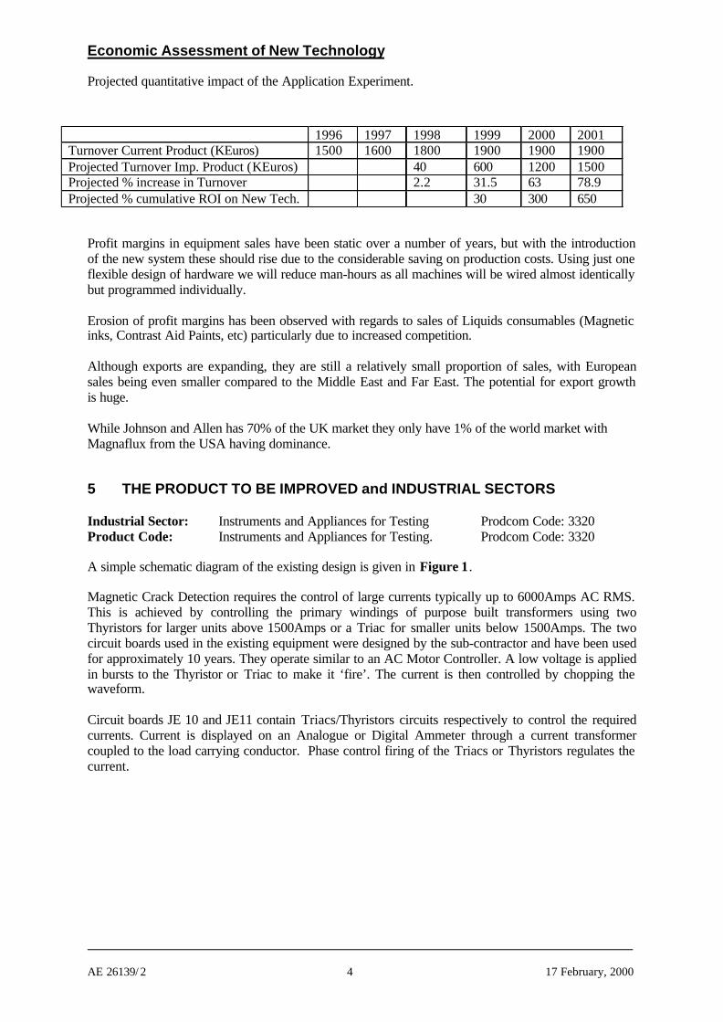
Projected quantitative impact of the Application Experiment.
Profit margins in equipment sales have been static over a number of years, but with the introductionof the new system these should rise due to the considerable saving on production costs. Using just oneflexible design of hardware we will reduce man-hours as all machines will be wired almost identicallybut programmed individually.
Erosion of profit margins has been observed with regards to sales of Liquids consumables (Magneticinks, Contrast Aid Paints, etc) particularly due to increased competition.
Although exports are expanding, they are still a relatively small proportion of sales, with Europeansales being even smaller compared to the Middle East and Far East. The potential for export growthis huge.
While Johnson and Allen has 70% of the UK market they only have 1% of the world market withMagnaflux from the USA having dominance.
5 THE PRODUCT TO BE IMPROVED and INDUSTRIAL SECTORS
Industrial Sector: Instruments and Appliances for Testing Prodcom Code: 3320Product Code: Instruments and Appliances for Testing. Prodcom Code: 3320
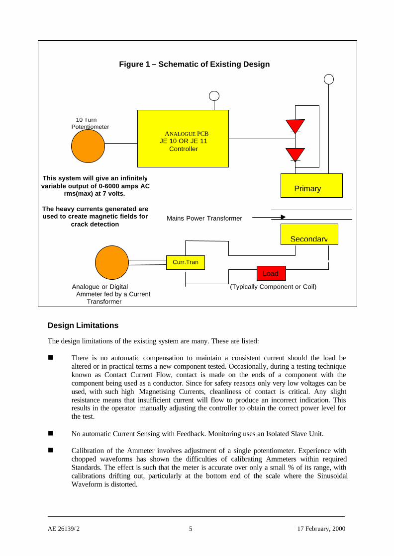
A simple schematic diagram of the existing design is given in Figure 1.
Magnetic Crack Detection requires the control of large currents typically up to 6000Amps AC RMS.This is achieved by controlling the primary windings of purpose built transformers using twoThyristors for larger units above 1500Amps or a Triac for smaller units below 1500Amps. The twocircuit boards used in the existing equipment were designed by the sub-contractor and have been usedfor approximately 10 years. They operate similar to an AC Motor Controller. A low voltage is appliedin bursts to the Thyristor or Triac to make it ‘fire’. The current is then controlled by chopping thewaveform.
Circuit boards JE 10 and JE11 contain Triacs/Thyristors circuits respectively to control the requiredcurrents. Current is displayed on an Analogue or Digital Ammeter through a current transformercoupled to the load carrying conductor. Phase control firing of the Triacs or Thyristors regulates thecurrent.
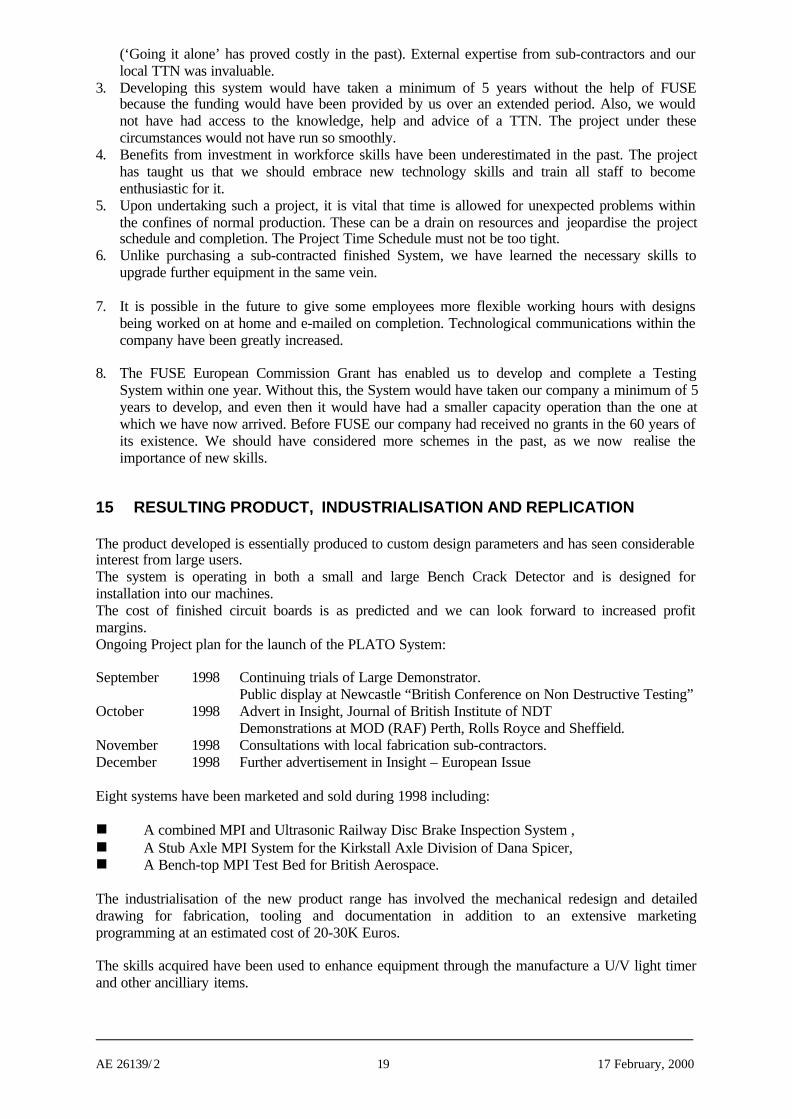
1996 1997 1998 1999 2000 2001Turnover Current Product (KEuros) 1500 1600 1800 1900 1900 1900Projected Turnover Imp. Product (KEuros) 40 600 1200 1500Projected % increase in Turnover 2.2 31.5 63 78.9Projected % cumulative ROI on New Tech. 30 300 650
AE 26139/ 2 5 17 February, 2000
Figure 1 – Schematic of Existing Design
10 TurnPotentiometer
Mains Power Transformer
Analogue or Digital (Typically Component or Coil) Ammeter fed by a Current
Transformer
Design Limitations
The design limitations of the existing system are many. These are listed:
n There is no automatic compensation to maintain a consistent current should the load bealtered or in practical terms a new component tested. Occasionally, during a testing techniqueknown as Contact Current Flow, contact is made on the ends of a component with thecomponent being used as a conductor. Since for safety reasons only very low voltages can beused, with such high Magnetising Currents, cleanliness of contact is critical. Any slightresistance means that insufficient current will flow to produce an incorrect indication. Thisresults in the operator manually adjusting the controller to obtain the correct power level forthe test.
n No automatic Current Sensing with Feedback. Monitoring uses an Isolated Slave Unit.
n Calibration of the Ammeter involves adjustment of a single potentiometer. Experience withchopped waveforms has shown the difficulties of calibrating Ammeters within requiredStandards. The effect is such that the meter is accurate over only a small % of its range, withcalibrations drifting out, particularly at the bottom end of the scale where the SinusoidalWaveform is distorted.
ANALOGUE PCBJE 10 OR JE 11
Controller
Secondary
Primary
Load
Curr.Tran
This system will give an infinitelyvariable output of 0-6000 amps AC
rms(max) at 7 volts.
The heavy currents generated areused to create magnetic fields for
crack detection
AE 26139/ 2 6 17 February, 2000
n Demagnetisation sequences, e.g. Decaying AC Rundown or Reversing Polarity Magnet Flow,are set during manufacture and hard wired. Experimentation to achieve the most satisfactoryresults is only possible with the removal and replacement of individual Resistors andCapacitors. This means that often the fine tuning of demagnetising systems is an unscientificlengthy process accomplished by trial and error.
n For Automated Systems the old type Controllers have to be hard wired to standard PLC’s or anumber of domino type timing systems. These dual systems have been costly to manufactureand are inflexible.
n Measurement of Magnetic Field Strengths around the component, to determine test integrityand also remnance after Demagnetisation, mean the acquisition of at least one, or two,calibrated Magnetometers or Tesla Meters.
n New American Aerospace Standards now specify Timed Magnetising Shots, this requiresadditions to the existing equipment for sales to the American market.
n The existing product has no provision to memorise and recall details of a test sequence.Operators are expected to keep records of Current Values and Modes e.g. Coil, Threader Baror Contact Current Flow and manually re-enter these values for each and every test.
n Test Techniques are frequently written with magnetising values stated in RMS Average orPeak. Conversion at present involves calculation by the operator.
n There are no Current Sensing or Magnetic Field Sensing devices to inform the operator of anunsatisfactory Magnetisation or Demagnetisation. Similarly, there are no Internal SystemMonitors warning of faults, e.g. Magnetising Coil short circuits and ‘no-contact’ situations inautomatic machines. In practice, this has meant critical components evading their designatedtests and their release into production with possible catastrophic effect.
6 DESCRIPTION OF THE TECHNICAL PRODUCT IMPROVEMENTS
The new product now uses a microcontroller to provide:
n accurate calibrated currents in the range 75-6000 amps,n preset AC, DC, 1/2 wave and ramped currents,n operator control and programming of auto sequences,n optional automatic recording of parameters and test results.
Current sensing using Hall Effect Probes, precision rms converter and an A-D converter is used toautomatically set and calibrate the current. Twenty-one calibrated scales each with 10 - 4 digit entries,give a total of 210 points in memory to an accuracy of 1%.
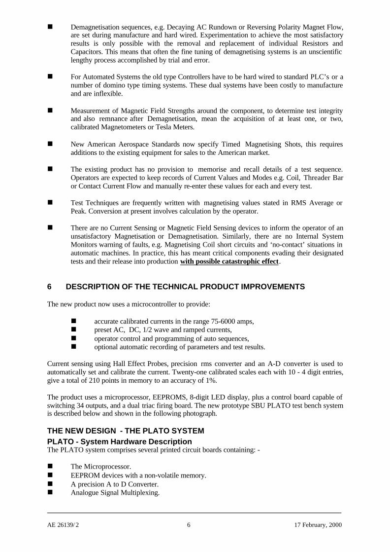
The product uses a microprocessor, EEPROMS, 8-digit LED display, plus a control board capable ofswitching 34 outputs, and a dual triac firing board. The new prototype SBU PLATO test bench systemis described below and shown in the following photograph.
THE NEW DESIGN - THE PLATO SYSTEMPLATO - System Hardware DescriptionThe PLATO system comprises several printed circuit boards containing: -
n The Microprocessor.n EEPROM devices with a non-volatile memory.n A precision A to D Converter.n Analogue Signal Multiplexing.
AE 26139/ 2 7 17 February, 2000
n Precision RMS Converter.n An 8 Digit 25mm ultra bright LED Display.n A Controller Board using a capable of switching 34 Outputs.n Both the Controller Board and LED displays are operated via 2 Wire Protocols.n 34 Outputs are used either as LED Indicators denoting System Modes, or, Opto Triac Relays
(Zero Crossing Type) switching up to 600VAC (100ma) powering Slave Relays for Auto-functions.
n Dual Triac or Quad Thryistor burst fire, firing board.
PLATO - an Integrated Answer
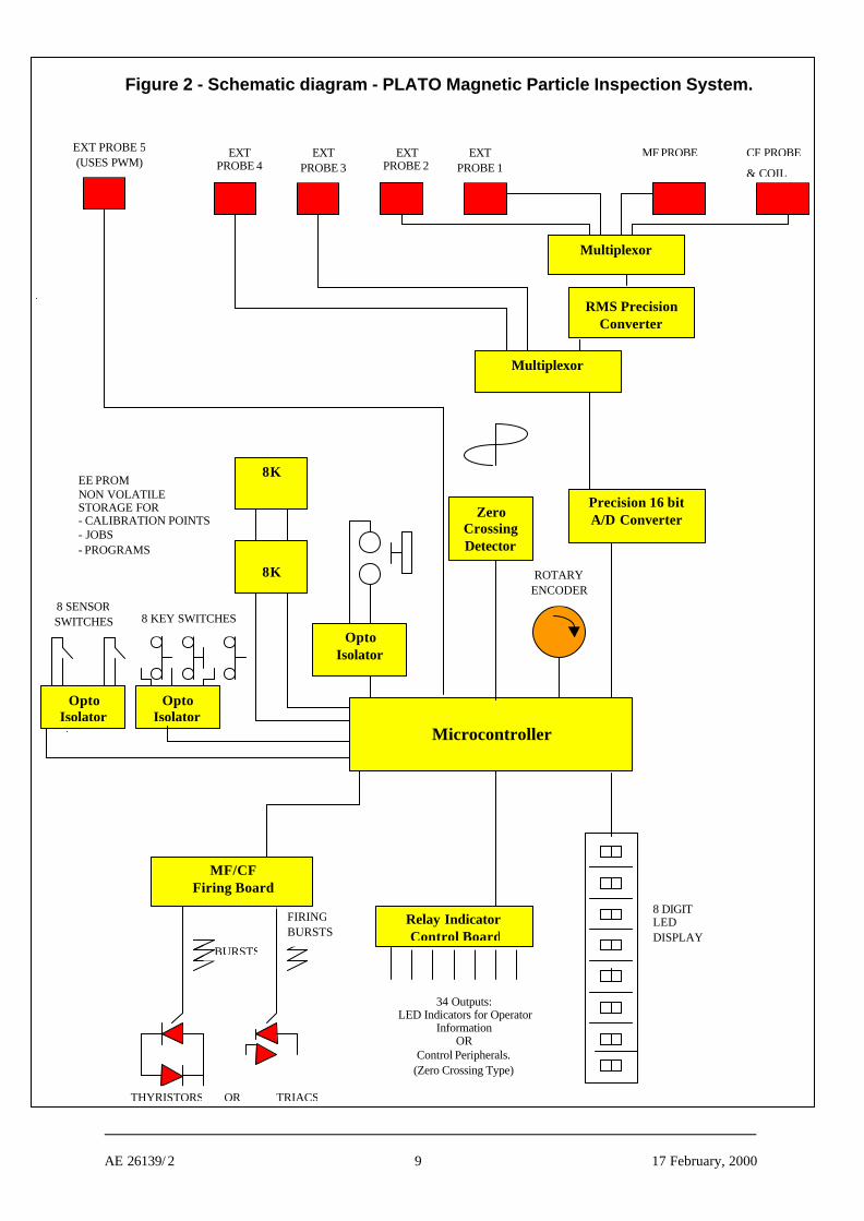
Figure 2 is a schematic diagram of the PLATO MPI System.
The Master Board contains the Microprocessor. A Non-volatile EEPROM stores 21 calibrated scaleseach with 10 - 4 digit entries, making a total of 210 points to be memorised in the calibration section.
Current Sensing uses Hall Effect Probes which feed, in the case of AC Fields, first through a precisionrms converter and then to the A to D. The OPTO isolated sequence start switch zero’s the selectedprobes every time a test is performed to eliminate temperature drift and spurious magnetic fields.
Previously needing 2 PCB’s to fire Thyristors or Triacs, a new Magnet Flow/Current Flow FiringBoard was designed to fire either. Firing of the Triacs and Thyristors is done in bursts giving a morepositive response with less likelihood of misfire due to the inductive loading. A Zero CrossingDetector was used to synchronize all firing and to enable accurate timing, which is to one millionth ofa second.
A new PCB Relay and Indicator Control Board was designed to give 34 Outputs. These Outputs maybe connected in different combinations to operate either LED Indicators or OPTO Triac Relays.
8 OPTO Isolated Key Switches used by the operator are input to the controller board and 8 OPTOIsolated Sensor Switches used for positional confirmation in automatic machines.
An 8 Digit ultra bright large LED Display was used for its robust qualities and wide viewing angle.
A Rotary Encoder was used to set the required current value, and to Recall and Save Job Memories.This Encoder in conjunction with the 8 Key Switches is also used to program Automatic Operationsby altering Control Perameters and Program ‘Token’ Values and steps.
In the early stages of development we became aware that there was a danger of the system becominginflexible. It was decided that the following parameters should remain flexible and capable of beingprogrammed into individual test units:
n Current Ramp Up and Ramp Down Speeds,n Rotary Encoder Response Characteristics,n Time Delays before Operator Warning Prompts displayed, andn The characteristic response of the Current Sensing and Feed Back Monitoring Loop.
Each parameter was assigned a symbol for the operator to ‘Dial Up’ and alter using the Encoder. Inthis way the whole behaviour of the machine can be moulded to accomplish a precise function.
For Automatic Operations a similar system of step ‘Tokens’ was created to enable operatorprogramming.
The Small Bench Unit 1000 prototype was built, (see Photo 1) with 40 program functions to create thefirst flexible system. The 40 ‘Tokens’ range from Time Delays, Current Values, % reductions of lastknown values and the switching of Relays, etc. All Values are stored in Non-volatile Memory.
AE 26139/ 2 8 17 February, 2000
Trials lasted about 3 months. During this period more program ‘Tokens’ were added as additionalfunctions were found to be desirable, expanding the flexibility of the end-use.
Emulation of the microprocessor was in real-time controlling mains power. Initially currents werecontrolled up to 200Amps rms slowly increasing up to 1500Amps rms as the project developed.
Photo 1
Small Bench UnitPLATO System
Prototype Test Bench
AE 26139/ 2 9 17 February, 2000
Figure 2 - Schematic diagram - PLATO Magnetic Particle Inspection System.
Multiplexor
Multiplexor
Precision 16 bitA/D Converter
8K
8K
Microcontroller
MF PROBE CF PROBE
& COIL
EXTPROBE 1
EXTPROBE 2
EXTPROBE 3
EXTPROBE 4
EXT PROBE 5(USES PWM)
PRECISION RMS/AVE CONVERTOR
ROTARYENCODER
OPTOISOLATOR
EE PROMNON VOLATILESTORAGE FOR- CALIBRATION POINTS- JOBS- PROGRAMS
8 KEY SWITCHES8 SENSORSWITCHES
8 DIGITLEDDISPLAY
RELAY INDICATORCONTROL BOARD
34 Outputs:LED Indicators for Operator
InformationOR
Control Peripherals.(Zero Crossing Type)
BURSTS
FIRINGBURSTS
TRIACSORTHYRISTORS
RMS PrecisionConverter
OptoIsolator
Relay IndicatorControl Board
OptoIsolator
OptoIsolator
ZeroCrossingDetector
MF/CFFiring Board
AE 26139/ 2 10 17 February, 2000
7 CHOICES AND RATIONALE FOR SELECTED TECHNOLOGIES
FABRICATION AND DESIGN METHODOLOGY
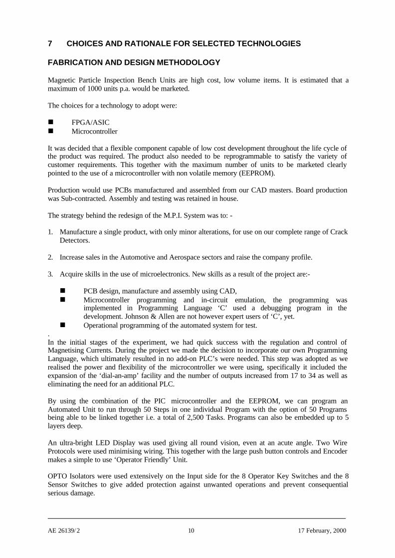
Magnetic Particle Inspection Bench Units are high cost, low volume items. It is estimated that amaximum of 1000 units p.a. would be marketed.
The choices for a technology to adopt were:
n FPGA/ASICn Microcontroller
It was decided that a flexible component capable of low cost development throughout the life cycle ofthe product was required. The product also needed to be reprogrammable to satisfy the variety ofcustomer requirements. This together with the maximum number of units to be marketed clearlypointed to the use of a microcontroller with non volatile memory (EEPROM).
Production would use PCBs manufactured and assembled from our CAD masters. Board productionwas Sub-contracted. Assembly and testing was retained in house.
The strategy behind the redesign of the M.P.I. System was to: -
1. Manufacture a single product, with only minor alterations, for use on our complete range of CrackDetectors.
2. Increase sales in the Automotive and Aerospace sectors and raise the company profile.
3. Acquire skills in the use of microelectronics. New skills as a result of the project are:-
n PCB design, manufacture and assembly using CAD,n Microcontroller programming and in-circuit emulation, the programming was
implemented in Programming Language ‘C’ used a debugging program in thedevelopment. Johnson & Allen are not however expert users of ‘C’, yet.
n Operational programming of the automated system for test..In the initial stages of the experiment, we had quick success with the regulation and control ofMagnetising Currents. During the project we made the decision to incorporate our own ProgrammingLanguage, which ultimately resulted in no add-on PLC’s were needed. This step was adopted as werealised the power and flexibility of the microcontroller we were using, specifically it included theexpansion of the ‘dial-an-amp’ facility and the number of outputs increased from 17 to 34 as well aseliminating the need for an additional PLC.
By using the combination of the PIC microcontroller and the EEPROM, we can program anAutomated Unit to run through 50 Steps in one individual Program with the option of 50 Programsbeing able to be linked together i.e. a total of 2,500 Tasks. Programs can also be embedded up to 5layers deep.
An ultra-bright LED Display was used giving all round vision, even at an acute angle. Two WireProtocols were used minimising wiring. This together with the large push button controls and Encodermakes a simple to use ‘Operator Friendly’ Unit.
OPTO Isolators were used extensively on the Input side for the 8 Operator Key Switches and the 8Sensor Switches to give added protection against unwanted operations and prevent consequentialserious damage.
AE 26139/ 2 11 17 February, 2000
Some of the operator benefits are listed below: -
1. Test sequences are automatic – the operator is not required to memorise test sequences, ormanually set and adjust testing modes.
2. Introduction of new test components require a simple reprogram to an existing test. Previously anew machine would be required.
3. The product has improved safety due to self monitoring.4. Improved Test Integrity – components cannot evade designated test values.5. Unique innovative highly accurate 10 Point Programmable Calibrations.
CHOICE OF DESIGN TOOLS
Following consultation and advice from the subcontractor the following design tools were purchased:-
n ‘MP Lab’ Integrated Development System for the PIC range of microprocessors.n ICE PIC-1 Emulator and daughter board used to emulate the PIC range of processors.
This was based on a PC and cost 3000 Euros .n ICE PIC-2 Emulator and daughter board with buffer to trace events emulated in real time.n EASY PC and ‘EDWIN’ for PCB Design and Routing, Claris Draw for drafting hardware.n Electronic Workbench EDA version for Analogue Analysis.
We were heavily reliant on the advice given by our sub-contractor in determining which design toolswere necessary. All the above systems were extensively used and our initial alarm in the capital outlayfor these was tempered by the fact that it very quickly became obvious that the system could not havebeen designed so effectively, efficiently or comprehensively without them.
It is now recognised that not only were these software packages essential for the experiment, but alsothat they constitute a huge potential for future equipment design.
CHOICE OF DESIGN ROUTE
The new skills needed for the new product offered the following options:-
1. Employ an Electronics Engineer with design capability. Cost Approx. 30K Eur p.a.2. Employ a Sub-contractor to design, test and manufacture the system . Cost Approx. 50K Eur3. Employ a Sub-contractor to train existing staff in the use of design tools in microelectronics and
programming. Cost Approx. 25K Eur
Option 1 was regarded as high risk. With only one person working on the project progress may beslow. Expertise would be confined to the new employee and existing employees would have noopportunity to upgrade their skills.
Option 2 was also rejected, we would rely totally on the sub-contractor. After development the supplyand maintenance of the systems would be out of our control, our name would only be as good as ourSub-contractors.
Option 3 was chosen as the most sustainable way of long term benefit to the Company. Although thisappeared the most cost effective option, at least an equivalent amount of money would be spent in thetime it would take existing employees to take up the skills necessary.
8 EXPERTISE AND EXPERIENCE
Established in 1938 Johnson and Allen have designed both standard and bespoke Magnetic ParticleInspection Equipment. Although highly experienced in NDT techniques and systems (includingcomponent handling), electronic design has previously been sub-contracted giving staff little
AE 26139/ 2 12 17 February, 2000
appreciation of the techniques involved and an inability to advance skills in this field. Staff havepreviously assembled the machines using timers and pneumatic logic
Four staff were involved in the project.
The Managing Director (with 20 years experience in NDT) and the Design/Technical Manager (with25+ years experience designing MPI units). Two other technician staff were involved in the PCBdesign and microcontroller programming and had no previous experience in these fields. One hadlimited electronics experience the other had wired MPI Bench Units for 20 years.
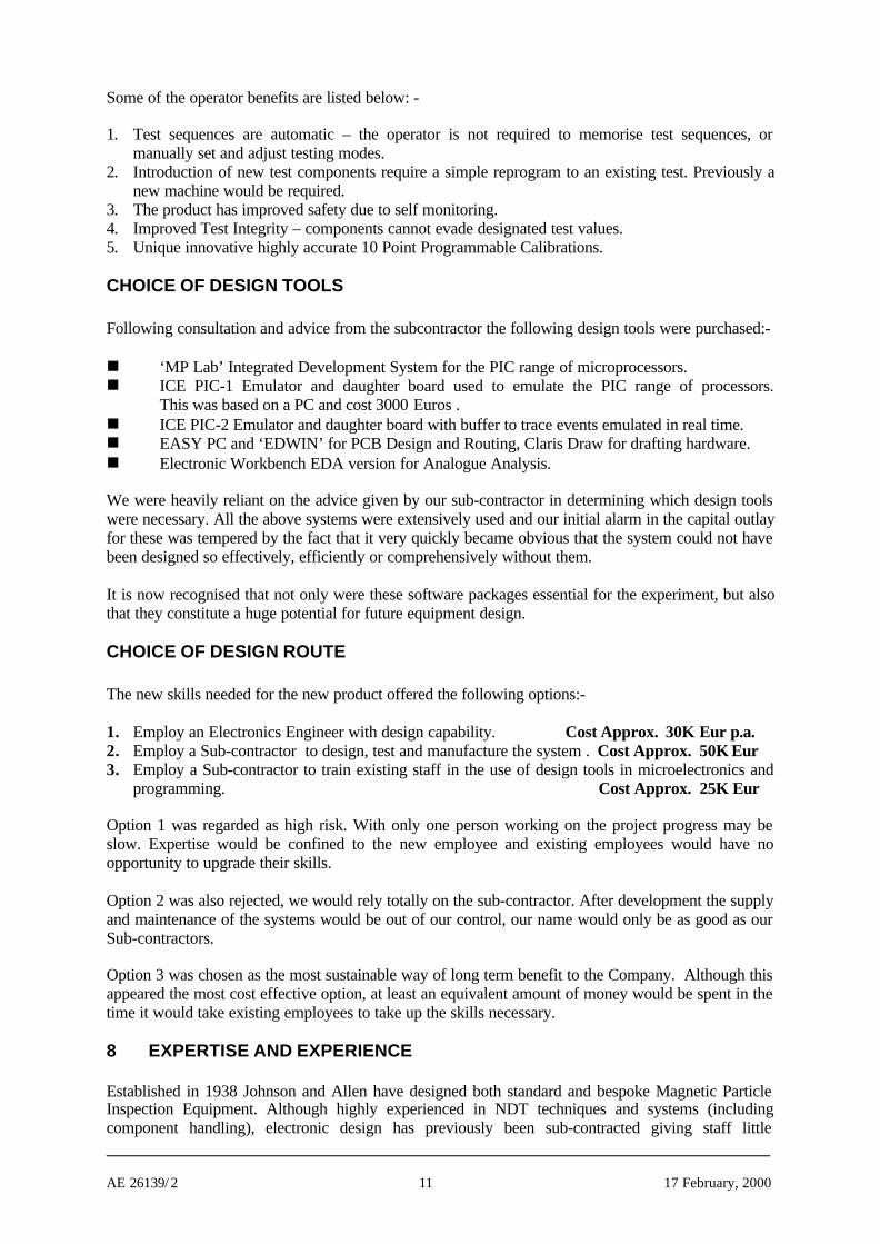
9 WORK PLAN AND RATIONALEBelow are details of the Workplan. It can be seen there is little deviation between the planned andactual days accounted for although mention must be made that many hours of homework, practisingand perfecting CAD are not recorded.
We found that the Workplan in conjunction with our Schedule of Deliverables an invaluable aid inensuring that the Project did not slip behind time. Ongoing production commitments were also able to
Planned Days Actual DaysJohnson & AllenJohnson& Allen
Subcontr. Johnson & Allen
Subcontr.CostsKEuros
4.1.1 ManagementPlan, Manage 4 4 5Report, 8 0 7Dissemination, 7 0 4Total 19 4 16 1.5
4.1.2 SpecificationFunctional 5 0 7System 7 0 12Technical 3 0 10Total 15 0 29
4.1.3 TrainingManagement 2 1 2Specific Training 0 0 0CAD training for PCBs 6 3 6Design 3 3 3PCB Design Tools 3 3 3Total 14 10 14 4.3
4.1.4 DesignFunctional Top Down 2 2 3
Software & Hardware Design 3 15 2Prototype Production 2 3 2Software Design & Simulation 0 15 2
Total 7 35 9 17.0
4.1.5 EvaluationPrototype Production 0 0 0
Test Rig 10 0 9Functional Test 10 2 13Prototype Test 5 3 7Full Test to Design Spec 44 5 42Total 69 10 71 2.5
Planned ActualFirst User Effort 121 123
Subcontractor Effort/Costs (days/KEuros) 64 25.3
AE 26139/ 2 13 17 February, 2000
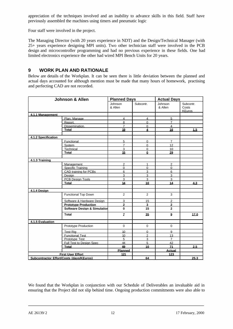
Graph depicting - Spread of Manpower and Monthly Progress of Project
-505
1015202530354045
Aug Oct
Dec
Feb
Apr
il
June
Work Task completion- No. of days early oflateNo. of EmployeeWorkdays assigned tocomplete tasksNo. of Sub-contractorWorkdays assigned tocomplete tasks
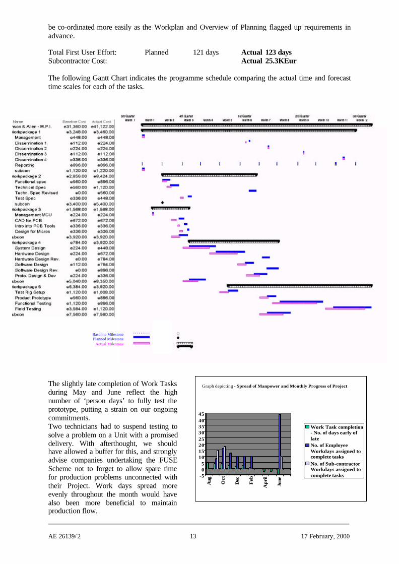
be co-ordinated more easily as the Workplan and Overview of Planning flagged up requirements inadvance.
Total First User Effort: Planned 121 days Actual 123 daysSubcontractor Cost: Actual 25.3KEur
The following Gantt Chart indicates the programme schedule comparing the actual time and forecasttime scales for each of the tasks.
The slightly late completion of Work Tasksduring May and June reflect the highnumber of ‘person days’ to fully test theprototype, putting a strain on our ongoingcommitments.Two technicians had to suspend testing tosolve a problem on a Unit with a promiseddelivery. With afterthought, we shouldhave allowed a buffer for this, and stronglyadvise companies undertaking the FUSEScheme not to forget to allow spare timefor production problems unconnected withtheir Project. Work days spread moreevenly throughout the month would havealso been more beneficial to maintainproduction flow.
Baseline MilestonePlanned Milestone
Actual Milestone

AE 26139/ 2 14 17 February, 2000
ACTUAL PROJECT COSTSThe predicted costs in (KEur) of the experiment were broken down as follows: -
Labour Cost 12.32Travel and Subsistence 2.965Durable Equipment 5.576Consumables 2Services 3.2Sub-contract Services 19.04TOTAL 45.101
Cost Statements were filed monthly, as well as Monitoring Technical Reports detailing progress.
The above labour costs are also shown as baseline costs on the previous Gantt Chart.
The observed overspend was due to added features introduced to the Technical Specification andimplemented at the Companies expense.The following charts indicate: -
A) Predicted & Actual Cumulative expenditure. B) Over/Under expenditure
NOTE: -
Although at first hand the Over Expenditure may seem excessive, it should be noted that a consciousdecision was made during the project to design our own Program Language Commands. There was aprojected overspend of 3000 Euros even had we not added to the perceived Testing System. Thisrepresents a deviation of approximately 8%, half of which can be attributed to deviation of ExchangeRates, with the other half an acceptable figure for an R & D Project.
The total planned over expenditure born by the Company represents an investment in a more powerfultest system with a greater flexibility to achieve automation of the most complex Magnetic CrackDetector perceived. Failure to incorporate the new facilities, would mean a far greater capital outlay ata later date, this made us press forward to complete an advanced finished package.
Graph BA comparison of Actual Over/Under Expenditure (Eur)
with compensated Over/Under Expenditure to removeadditional costs generated by increasing the Systems
processing power
-5000
0
5000
10000
15000
20000
Aug Oct
Dec
Feb
Apr
il
June
Actual CumulativeOver/Under Spend
CompensatedAcumulativeOver/Under Spend
Graph APredicted and Actual Cumulative
Expenditure (Eur)
-10000
0
10000
20000
3000040000
50000
60000
70000
Aug
Oct
Dec
Feb
Apr
il
June
Actual CumulativeExpenditureProjected CumulativeExpendatureOver/Under Spend
AE 26139/ 2 15 17 February, 2000
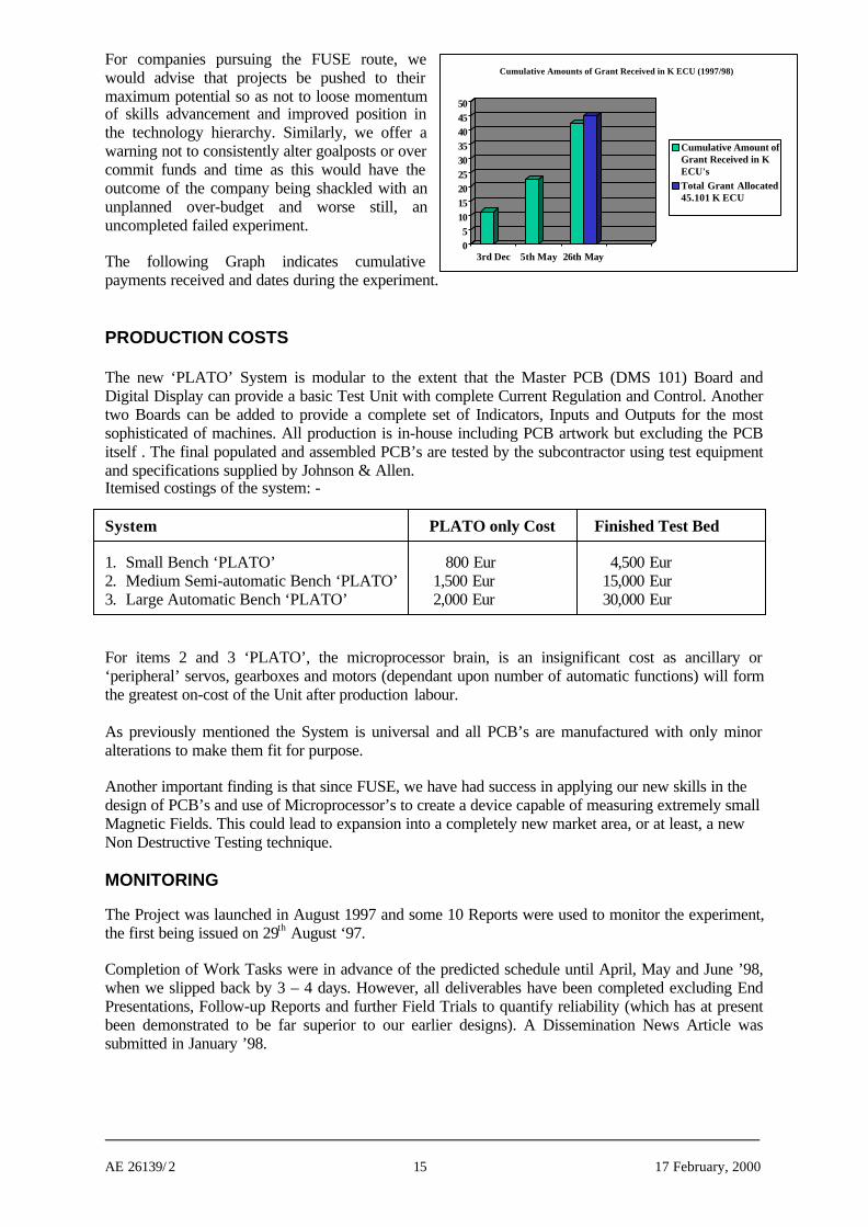
Cumulative Amounts of Grant Received in K ECU (1997/98)
05
101520253035404550
3rd Dec 5th May 26th May
Cumulative Amount ofGrant Received in KECU's Total Grant Allocated45.101 K ECU
For companies pursuing the FUSE route, wewould advise that projects be pushed to theirmaximum potential so as not to loose momentumof skills advancement and improved position inthe technology hierarchy. Similarly, we offer awarning not to consistently alter goalposts or overcommit funds and time as this would have theoutcome of the company being shackled with anunplanned over-budget and worse still, anuncompleted failed experiment.
The following Graph indicates cumulativepayments received and dates during the experiment.
PRODUCTION COSTS
The new ‘PLATO’ System is modular to the extent that the Master PCB (DMS 101) Board andDigital Display can provide a basic Test Unit with complete Current Regulation and Control. Anothertwo Boards can be added to provide a complete set of Indicators, Inputs and Outputs for the mostsophisticated of machines. All production is in-house including PCB artwork but excluding the PCBitself . The final populated and assembled PCB’s are tested by the subcontractor using test equipmentand specifications supplied by Johnson & Allen.Itemised costings of the system: -
System PLATO only Cost Finished Test Bed
1. Small Bench ‘PLATO’ 800 Eur 4,500 Eur2. Medium Semi-automatic Bench ‘PLATO’ 1,500 Eur 15,000 Eur3. Large Automatic Bench ‘PLATO’ 2,000 Eur 30,000 Eur
For items 2 and 3 ‘PLATO’, the microprocessor brain, is an insignificant cost as ancillary or‘peripheral’ servos, gearboxes and motors (dependant upon number of automatic functions) will formthe greatest on-cost of the Unit after production labour.
As previously mentioned the System is universal and all PCB’s are manufactured with only minoralterations to make them fit for purpose.
Another important finding is that since FUSE, we have had success in applying our new skills in thedesign of PCB’s and use of Microprocessor’s to create a device capable of measuring extremely smallMagnetic Fields. This could lead to expansion into a completely new market area, or at least, a newNon Destructive Testing technique.
MONITORING
The Project was launched in August 1997 and some 10 Reports were used to monitor the experiment,the first being issued on 29th August ‘97.
Completion of Work Tasks were in advance of the predicted schedule until April, May and June ’98,when we slipped back by 3 – 4 days. However, all deliverables have been completed excluding EndPresentations, Follow-up Reports and further Field Trials to quantify reliability (which has at presentbeen demonstrated to be far superior to our earlier designs). A Dissemination News Article wassubmitted in January ’98.
AE 26139/ 2 16 17 February, 2000
Specification
The System Specification, as detailed in Section 2 of this document, was completed a littlelate because of the additional expansion of the ‘PLATO’ System which occurred later in theProject. The end result was, however, the creation of a considerably higher Specification thanoriginally sought. The specification was the responsibility of the first user but considerableassistance in detail given by the subcontractor.
Training
All training undertaken was completed on time, this being the area that followed theWorkplan to the greatest accuracy.
All training was given by S & S Systems with the total training period amounting to 14 days.Sub-contract training was completed early in November ’97, but learning continuedthroughout the spring of 1998 as the Project matured.
CAD experience involved the use of ‘Easy PC’ and ‘EDWIN’ Systems together with MPLAB and the software previously described in the Design Tools section.
Design
The design of the System occurred in two phases. The first phase during Sept. – Dec. ’97 andthe second phase, (with the design modification), in Feb. and March ’98. The experimentobjective had been achieved with the initial design and this was expanded upon in the secondphase when a new potential was realised. Although much of the design theory was sub-contract generated, the plotting of PCB’s, Hardware and the Microchip Design Tools were allused by our company to provide the finished System.
All the detailed electronic circuit design was undertaken by the subcontractor, S & S Systemswith day to day discussions with the first user.
Evaluation
A small working Prototype was constructed with ongoing test starting from Nov. ’97. Thiswas run through an Emulator enabling us to trial many different Programs, assess theirsuccess and slowly build the System Software piece by piece.Finally a Large Bench Crack Detector was trialed using the System perfected on thePrototype. The prototype electronic circuitsJohnson & Allen was responsible for the complete evaluation of the prototype, a little helpfrom the subcontractor was necessary when dealing with the programming for specificcustomer requirements.
10 SUBCONTRACTOR INFORMATIONS & S Systems Ltd.Bretton Court,Manor Road, Wales VillageSheffield S26 5PSe-mail [email protected]
S & S Systems Ltd. is a privately owned company specialising in electronic design, manufacture andservicing.Mr Stephen Alsop (the Managing Director) controlled the subcontracted aspects of the project andwas involved in 90% of all CAD training, including Microprocessor Programming. The unique‘PLATO’ System, its complexity, its flexibility, and its innovative operation, is as much atestament to his dedication to the project as it is to our own.
AE 26139/ 2 17 17 February, 2000
S & S Systems role in Johnson & Allen’s Application Experiment was as follows:
1. Training - Software Design, CAD, PCB, Microchips- Programming- Hardware Interaction and Integration with Software.
2. Assessment, Evaluation & Planning - Choosing the Hardware, Software and application route
3. Technical Consultation - Liaising with staff on problems encountered and solutions +Interceded when our own designs were flawed saving bothtime and effort.
4. Design - The electronic system and circuit design.
The fact that the Project has been successfully completed, that we have a finished saleable item andthat we have the staff to implement it, is proof that S & S Systems were unquestionably the rightcompany for us to use for this job
11 BARRIERS PERCEIVEDA number of obstacles were perceived at the start of the experiment with decisions being taken duringthe exercise to minimize or remove their effect upon the Company. Two barriers which were presentduring the implementation of the experiment are detailed below.
Technical RisksThese were very hard to quantify, but taking into consideration that the finished System was to beplaced into the Aerospace market, any inadequacies or poor design could well backfire on thecompany in a dramatic and damaging way. This would have the complete reverse effect to that whichwas desired.
Another danger was that the experiment would fail in the design stage, and much time, energy andcapital would be poured into this new technology giving little return and a poor unsaleable Systemupon completion of the project. This would constitute a bad experience with a loss of confidence inthe new skills learnt making them harder to apply in the future.
Being accepted into the Fuse Scheme gave us the assurance that we would be advised and supportedby both the Sub-contractor and our local TTN (The Bolton Institute). Gaining the grant has meant thedifference between appreciating new technology skills (but remaining their slave), to actuallymastering them as a production tool.
Employee motivation and enthusiasm was beyond all our expectations. With the direct involvement ofthe staff and with the trust placed with them, the team spirit definitely played an important role inseeming to minimise the technical risks. Fuse had given us all the confidence and skilled technicalexpertise to realise our expectations.
Commercial Risks
The considered commercial risks were as follows: -
n Loss of productivity whilst employees were being trained. This was solved partly by the Sub-contractor being flexible to the needs of the company and by re-arranging training days togive the best use of staff.
n To ensure that the technology adopted was appropriate and the technical risk thereforeminimised.
AE 26139/ 2 18 17 February, 2000
n The System must be innovative enough to be immediately accepted and desired by thecustomer and that the sales predictions should be accurate.
It must be stated that R & D and training within the company had been cautious and limited in thepast. Without the solidarity of the FUSE Program it would seem unlikely that we would have arrivedat this level of sophistication without a 5-year development period.
The possible economic advantage of being the leader in our particular field far outweighed thecommercial risks. The PLATO System is only just being advertised, but we have the conviction that itwill sell itself after being placed in ‘flagship’ companies.
12 STEPS TAKEN TO OVERCOME BARRIERS
Support for the project came from two main sources:
n Management of a project utilising new technology was seen as a major obstacle. The TTNhelped with a comprehensive plan of work, advice and monitoring progress. This was usefulin leading us through a project and technology new to us.
n Several aspects of technology totally outside our experience were daunting. A subcontractorwho had a clearly defined task and showed enthusiasm to implement and complete wasinvaluable. In addition to contributing with technical advice throughout the project thesubcontractor was very communicative.
13 KNOWLEDGE AND EXPERIENCE ACQUIRED
Technical DesignJohnson & Allen Ltd. are now able to design their own PCB’s, programme Microchips and constructwholly integrated devices. Our new knowledge will help us prepare and modify technicalspecifications.Research and DevelopmentThe planning and overseeing of this large development project has given us an excellent grounding inproject work. Any future research project we undertake will be modelled on this.Advanced AutomationOur new knowledge means that we are now capable of producing the most sophisticated AutomatedMagnetic Particle Testing Systems available worldwide.Market ProgressionThe sophistication of our Systems will mean a progression of Units being supplied to the Aerospace,Automotive and Petrochemical Industries. This is directly attributable to our gain in knowledgewealth.Lower Production CostsOur new knowledge will give us lower production costs coupled with easier fault finding. OurHardware package will be almost identical in all Crack Detectors, with the exception of itsProgramming, which can easily be downloaded.Cost Effective ExportsAs we are more able to support equipment exported, by sending for example replacement Plug inCircuit Boards, there will be less time and money wasted in technicians travelling abroad. Export cannow be increased without an increase in after-sales service staff.
14 LESSONS LEARNED
1. A good understanding of the technology is necessary before fixing the specifications of thetargeted product.
2. Research and Development becomes more economic when entered into with a DocumentedProject Plan and when aided and supported by organisations experienced in the fields chosen.
AE 26139/ 2 19 17 February, 2000
(‘Going it alone’ has proved costly in the past). External expertise from sub-contractors and ourlocal TTN was invaluable.
3. Developing this system would have taken a minimum of 5 years without the help of FUSEbecause the funding would have been provided by us over an extended period. Also, we wouldnot have had access to the knowledge, help and advice of a TTN. The project under thesecircumstances would not have run so smoothly.
4. Benefits from investment in workforce skills have been underestimated in the past. The projecthas taught us that we should embrace new technology skills and train all staff to becomeenthusiastic for it.
5. Upon undertaking such a project, it is vital that time is allowed for unexpected problems withinthe confines of normal production. These can be a drain on resources and jeopardise the projectschedule and completion. The Project Time Schedule must not be too tight.
6. Unlike purchasing a sub-contracted finished System, we have learned the necessary skills toupgrade further equipment in the same vein.
7. It is possible in the future to give some employees more flexible working hours with designsbeing worked on at home and e-mailed on completion. Technological communications within thecompany have been greatly increased.
8. The FUSE European Commission Grant has enabled us to develop and complete a TestingSystem within one year. Without this, the System would have taken our company a minimum of 5years to develop, and even then it would have had a smaller capacity operation than the one atwhich we have now arrived. Before FUSE our company had received no grants in the 60 years ofits existence. We should have considered more schemes in the past, as we now realise theimportance of new skills.
15 RESULTING PRODUCT, INDUSTRIALISATION AND REPLICATION
The product developed is essentially produced to custom design parameters and has seen considerableinterest from large users.The system is operating in both a small and large Bench Crack Detector and is designed forinstallation into our machines.The cost of finished circuit boards is as predicted and we can look forward to increased profitmargins.Ongoing Project plan for the launch of the PLATO System:
September 1998 Continuing trials of Large Demonstrator.Public display at Newcastle “British Conference on Non Destructive Testing”
October 1998 Advert in Insight, Journal of British Institute of NDTDemonstrations at MOD (RAF) Perth, Rolls Royce and Sheffield.
November 1998 Consultations with local fabrication sub-contractors.December 1998 Further advertisement in Insight – European Issue
Eight systems have been marketed and sold during 1998 including:
n A combined MPI and Ultrasonic Railway Disc Brake Inspection System ,n A Stub Axle MPI System for the Kirkstall Axle Division of Dana Spicer,n A Bench-top MPI Test Bed for British Aerospace.
The industrialisation of the new product range has involved the mechanical redesign and detaileddrawing for fabrication, tooling and documentation in addition to an extensive marketingprogramming at an estimated cost of 20-30K Euros.
The skills acquired have been used to enhance equipment through the manufacture a U/V light timerand other ancilliary items.

AE 26139/ 2 20 17 February, 2000
At the present moment in time, we have designed no other microprocessor PCB’s as we are only justarriving at the end of our Application Experiment.This Project generated four different PCB’s, one being the Microprocessor Board.
We have plans to examine the feasibility of designing:
n A Controller to operate Automatic Dye Penetrant Inspection Lines.(Dye Penetrant Testing being the second largest aspect of our business).
n We also intend to investigate the development of a sensitive Gauss Probe and possible newmarket areas.
These products could both be improved once we have capitalised on the ‘PLATO’ System.
16 ECONOMIC IMPACT AND IMPROVEMENT IN COMPETITIVE POSITION
The table below projects the expected increase in turnover in the Aerospace sector. This is aconservative estimate based on figures covering the previous 5 years, 1992 – 1997.
Year 1 (1998) 30K Eur Expected ordersYear 2 (1999) 120K Eur Expected ordersYear 3 (2000) 250K Eur Expected orders based on realistic predictions.
Note: Since the above figures are for the Aerospace Industry only, when other markets are taken intoconsideration it would be prudent to assume that the total expected increase in turnover would be inexcess of twice the above projected figures.It is believed that 50% of the monies generated by the new system will be as a direct result of amarket shift from our competitors, the remaining 50% being generated from completely new contacts.The new contacts being customers who find that only our system has the required capabilities for theirpurpose.
Our competitive position will also be improved, as the same system will be used in our completerange of MPI Bench Units. This results in all units being wired identically but programmedindividually, and will represent a considerable cost saving in man-hours. The ‘on’ cost of this newsystem to the customer will be insignificant taking the equipment as a whole. Whilst giving thecustomer a greater range of Test Options and Automation, it will also give them the advantage ofsuperior calibration, accuracy and repeatability of test.
Price Example: Present System - Large Aerospace MPI Bench Unit - typical cost 30K EurNew System - Large Aerospace MPI Bench Unit,
Programmable, Automated and with Memory - 32K Eur
Therefore for less than 10% ‘on’ cost the customer is investing in the most flexible, integrated andadvanced system available at the present time.
The following table indicates the overall turnover predicted. The payback period for the investment of45Keuros is estimated as 12 months and the conservative prediction of a 10-fold return on investmentover the life of the product if the figures prove to be accurate.
1996 1997 1998 1999 2000 2001Turnover Current Product 1500 1600 1800 1900 1900 1900Projected Turnover Improved Product 40 600 1200 1500
AE 26139/ 2 21 17 February, 2000
Projected % increase in Turnover 2.2 31.5 63 78.9Projected % cumulative ROI on NewTechnology
30 300 650
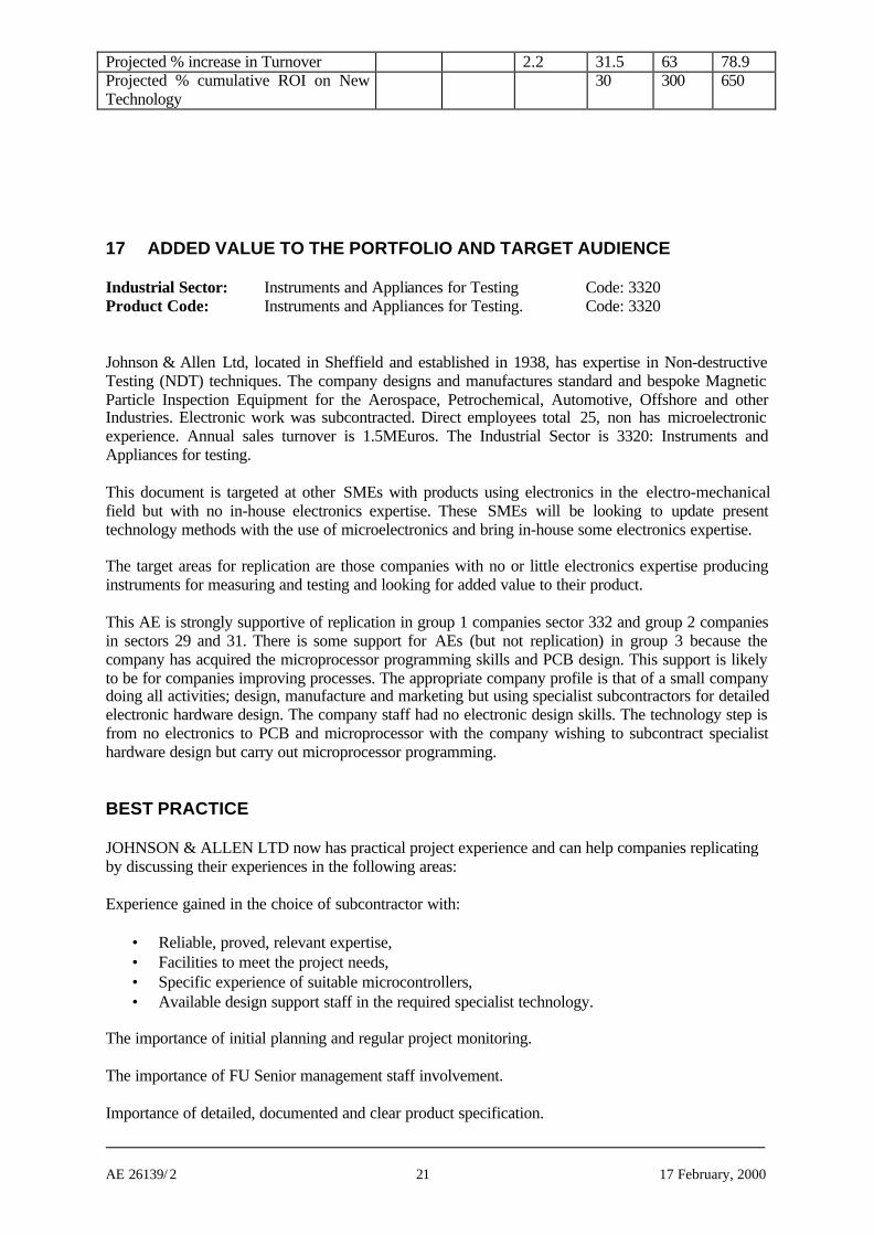
17 ADDED VALUE TO THE PORTFOLIO AND TARGET AUDIENCE
Industrial Sector: Instruments and Appliances for Testing Code: 3320Product Code: Instruments and Appliances for Testing. Code: 3320
Johnson & Allen Ltd, located in Sheffield and established in 1938, has expertise in Non-destructiveTesting (NDT) techniques. The company designs and manufactures standard and bespoke MagneticParticle Inspection Equipment for the Aerospace, Petrochemical, Automotive, Offshore and otherIndustries. Electronic work was subcontracted. Direct employees total 25, non has microelectronicexperience. Annual sales turnover is 1.5MEuros. The Industrial Sector is 3320: Instruments andAppliances for testing.
This document is targeted at other SMEs with products using electronics in the electro-mechanicalfield but with no in-house electronics expertise. These SMEs will be looking to update presenttechnology methods with the use of microelectronics and bring in-house some electronics expertise.
The target areas for replication are those companies with no or little electronics expertise producinginstruments for measuring and testing and looking for added value to their product.
This AE is strongly supportive of replication in group 1 companies sector 332 and group 2 companiesin sectors 29 and 31. There is some support for AEs (but not replication) in group 3 because thecompany has acquired the microprocessor programming skills and PCB design. This support is likelyto be for companies improving processes. The appropriate company profile is that of a small companydoing all activities; design, manufacture and marketing but using specialist subcontractors for detailedelectronic hardware design. The company staff had no electronic design skills. The technology step isfrom no electronics to PCB and microprocessor with the company wishing to subcontract specialisthardware design but carry out microprocessor programming.
BEST PRACTICE
JOHNSON & ALLEN LTD now has practical project experience and can help companies replicatingby discussing their experiences in the following areas:
Experience gained in the choice of subcontractor with:
• Reliable, proved, relevant expertise,• Facilities to meet the project needs,• Specific experience of suitable microcontrollers,• Available design support staff in the required specialist technology.
The importance of initial planning and regular project monitoring.
The importance of FU Senior management staff involvement.
Importance of detailed, documented and clear product specification.
AE 26139/ 2 22 17 February, 2000
DOCUMENTS AVAILABLE
A dissemination article was published in Jan. 1998 for the European FUSE Newsletter.High level publicity has been made available to provide marketing through:
n An article in ‘Insight’ the Journal of the British Institute of Non Destructive Testing, inOctober 1998.
n The American Society for NDT (ASNT) Conference, Chicago, 1998.n Quality Control Division, Rolls-Royce.n Marketing the new product will be through the new demonstration centre we have opened
specifically for this purpose. The equipment will also be demonstrated using the new largeorders now received with prestigious customers.
n There are plans to highlight ‘FUSE’ in the Chamber of Commerce using their monthlynewsletter.
The promotional literature supplied to prospective customers emphasizes solidarity of effort betweenthe European Commission, the local TTN, the Sub-contractor and the Company, in an informativeway. The aim is to create a dialogue about the FUSE Scheme as much as to promote our new System.