
Magnetic Liquid Level Indicators - Powerflo
32
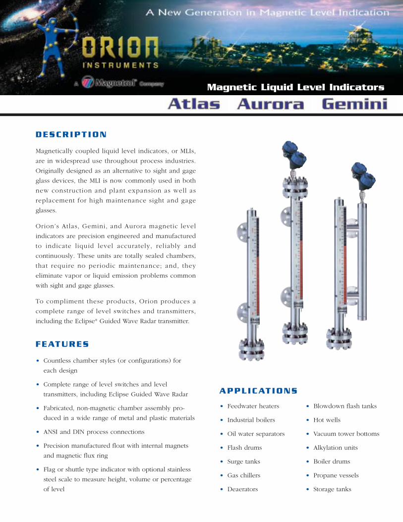
Magnetic Liquid Level Indicators DESCRIPTION Magnetically coupled liquid level indicators, or MLIs, are in widespread use throughout process industries. Originally designed as an alternative to sight and gage glass devices, the MLI is now commonly used in both new construction and plant expansion as well as replacement for high maintenance sight and gage glasses. Orion’s Atlas, Gemini, and Aurora magnetic level indicators are precision engineered and manufactured to indicate liquid level accurately, reliably and continuously. These units are totally sealed chambers, that require no periodic maintenance; and, they eliminate vapor or liquid emission problems common with sight and gage glasses. To compliment these products, Orion produces a complete range of level switches and transmitters, including the Eclipse ® Guided Wave Radar transmitter. FEATURES • Countless chamber styles (or configurations) for each design • Complete range of level switches and level transmitters, including Eclipse Guided Wave Radar • Fabricated, non-magnetic chamber assembly pro- duced in a wide range of metal and plastic materials • ANSI and DIN process connections • Precision manufactured float with internal magnets and magnetic flux ring • Flag or shuttle type indicator with optional stainless steel scale to measure height, volume or percentage of level APPLICATIONS • Feedwater heaters • Industrial boilers • Oil water separators • Flash drums • Surge tanks • Gas chillers • Deaerators • Blowdown flash tanks • Hot wells • Vacuum tower bottoms • Alkylation units • Boiler drums • Propane vessels • Storage tanks
Transcript of Magnetic Liquid Level Indicators - Powerflo
Magnetic Liquid Level Indicators
DESCRIPT ION
Magnetically coupled liquid level indicators, or MLIs,
are in widespread use throughout process industries.
Originally designed as an alternative to sight and gage
glass devices, the MLI is now commonly used in both
new construction and plant expansion as well as
replacement for high maintenance sight and gage
glasses.
Orion’s Atlas, Gemini, and Aurora magnetic level
indicators are precision engineered and manufactured
to indicate liquid level accurately, reliably and
continuously. These units are totally sealed chambers,
that require no periodic maintenance; and, they
eliminate vapor or liquid emission problems common
with sight and gage glasses.
To compliment these products, Orion produces a
complete range of level switches and transmitters,
including the Eclipse® Guided Wave Radar transmitter.
FEATURES
• Countless chamber styles (or configurations) for
each design
• Complete range of level switches and level
transmitters, including Eclipse Guided Wave Radar
• Fabricated, non-magnetic chamber assembly pro-
duced in a wide range of metal and plastic materials
• ANSI and DIN process connections
• Precision manufactured float with internal magnets
and magnetic flux ring
• Flag or shuttle type indicator with optional stainless
steel scale to measure height, volume or percentage
of level
APPLICATIONS
• Feedwater heaters
• Industrial boilers
• Oil water separators
• Flash drums
• Surge tanks
• Gas chillers
• Deaerators
• Blowdown flash tanks
• Hot wells
• Vacuum tower bottoms
• Alkylation units
• Boiler drums
• Propane vessels
• Storage tanks
2
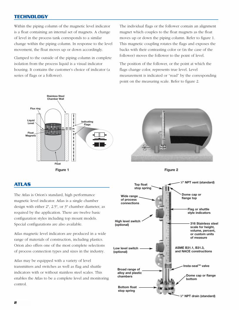
ATLAS
The Atlas is Orion’s standard, high performance
magnetic level indicator. Atlas is a single chamber
design with either 2", 2.5", or 3" chamber diameter, as
required by the application. There are twelve basic
configuration styles including top mount models.
Special configurations are also available.
Atlas magnetic level indicators are produced in a wide
range of materials of construction, including plastics.
Orion also offers one of the most complete selections
of process connection types and sizes in the industry.
Atlas may be equipped with a variety of level
transmitters and switches as well as flag and shuttle
indicators with or without stainless steel scales. This
enables the Atlas to be a complete level and monitoring
control.
TECHNOLOGY
Within the piping column of the magnetic level indicator
is a float containing an internal set of magnets. A change
of level in the process tank corresponds to a similar
change within the piping column. In response to the level
movement, the float moves up or down accordingly.
Clamped to the outside of the piping column in complete
isolation from the process liquid is a visual indicator
housing. It contains the customer’s choice of indicator (a
series of flags or a follower).
The individual flags or the follower contain an alignment
magnet which couples to the float magnets as the float
moves up or down the piping column. Refer to figure 1.
This magnetic coupling rotates the flags and exposes the
backs with their contrasting color or (in the case of the
follower) moves the follower to the point of level.
The position of the follower, or the point at which the
flags change color, represents true level. Level
measurement is indicated or “read” by the corresponding
point on the measuring scale. Refer to figure 2.
Wide rangeof processconnections
Dome cap orflange top
Flag or shuttlestyle indicators
Dome cap or flangebottom
High level switch(optional) 316 Stainless steel
scale for height,volume, percent,or custom unitsof measure
ASME B31.1, B31.3,and NACE constructions
Broad range ofalloy and plasticchambers
Bottom floatstop spring
Low level switch(optional)
Top floatstop spring
1⁄2" NPT drain (standard)
1⁄2" NPT vent (standard)
Insta-seal™ valve
Stainless SteelChamber Wall
FloatMagnets
LiquidLevel
Float
Flux ring
IndicatingFlags
Figure 1 Figure 2
3
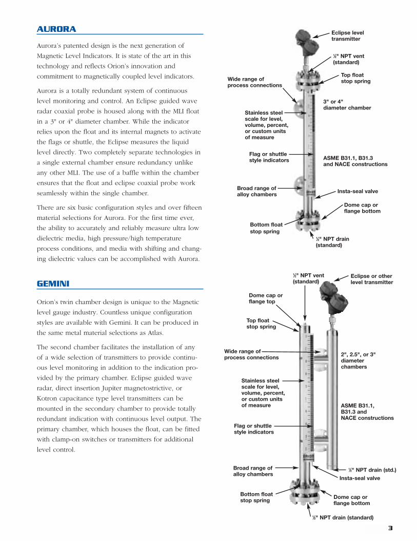
GEMINI
Orion’s twin chamber design is unique to the Magnetic
level gauge industry. Countless unique configuration
styles are available with Gemini. It can be produced in
the same metal material selections as Atlas.
The second chamber facilitates the installation of any
of a wide selection of transmitters to provide continu-
ous level monitoring in addition to the indication pro-
vided by the primary chamber. Eclipse guided wave
radar, direct insertion Jupiter magnetostrictive, or
Kotron capacitance type level transmitters can be
mounted in the secondary chamber to provide totally
redundant indication with continuous level output. The
primary chamber, which houses the float, can be fitted
with clamp-on switches or transmitters for additional
level control.
Wide range ofprocess connections
Dome cap orflange top
Flag or shuttlestyle indicators
Dome cap orflange bottom
Stainless steelscale for level,volume, percent,or custom unitsof measure ASME B31.1,
B31.3 andNACE constructions
Broad range ofalloy chambers
Bottom floatstop spring
Eclipse or otherlevel transmitter
2", 2.5", or 3"diameterchambers
AURORA
Aurora’s patented design is the next generation of
Magnetic Level Indicators. It is state of the art in this
technology and reflects Orion’s innovation and
commitment to magnetically coupled level indicators.
Aurora is a totally redundant system of continuous
level monitoring and control. An Eclipse guided wave
radar coaxial probe is housed along with the MLI float
in a 3" or 4" diameter chamber. While the indicator
relies upon the float and its internal magnets to activate
the flags or shuttle, the Eclipse measures the liquid
level directly. Two completely separate technologies in
a single external chamber ensure redundancy unlike
any other MLI. The use of a baffle within the chamber
ensures that the float and eclipse coaxial probe work
seamlessly within the single chamber.
There are six basic configuration styles and over fifteen
material selections for Aurora. For the first time ever,
the ability to accurately and reliably measure ultra low
dielectric media, high pressure/high temperature
process conditions, and media with shifting and chang-
ing dielectric values can be accomplished with Aurora.
Wide range ofprocess connections
Flag or shuttlestyle indicators
Dome cap orflange bottom
Stainless steelscale for level,volume, percent,or custom unitsof measure
ASME B31.1, B31.3and NACE constructions
Broad range ofalloy chambers
Bottom floatstop spring
Eclipse leveltransmitter
3" or 4"diameter chamber
Top floatstop spring
1⁄2" NPT vent(standard)
Top floatstop spring
1⁄2" NPT vent(standard)
1⁄2" NPT drain(standard)
Insta-seal valve
Insta-seal valve
1⁄2" NPT drain (std.)
1⁄2" NPT drain (standard)
4
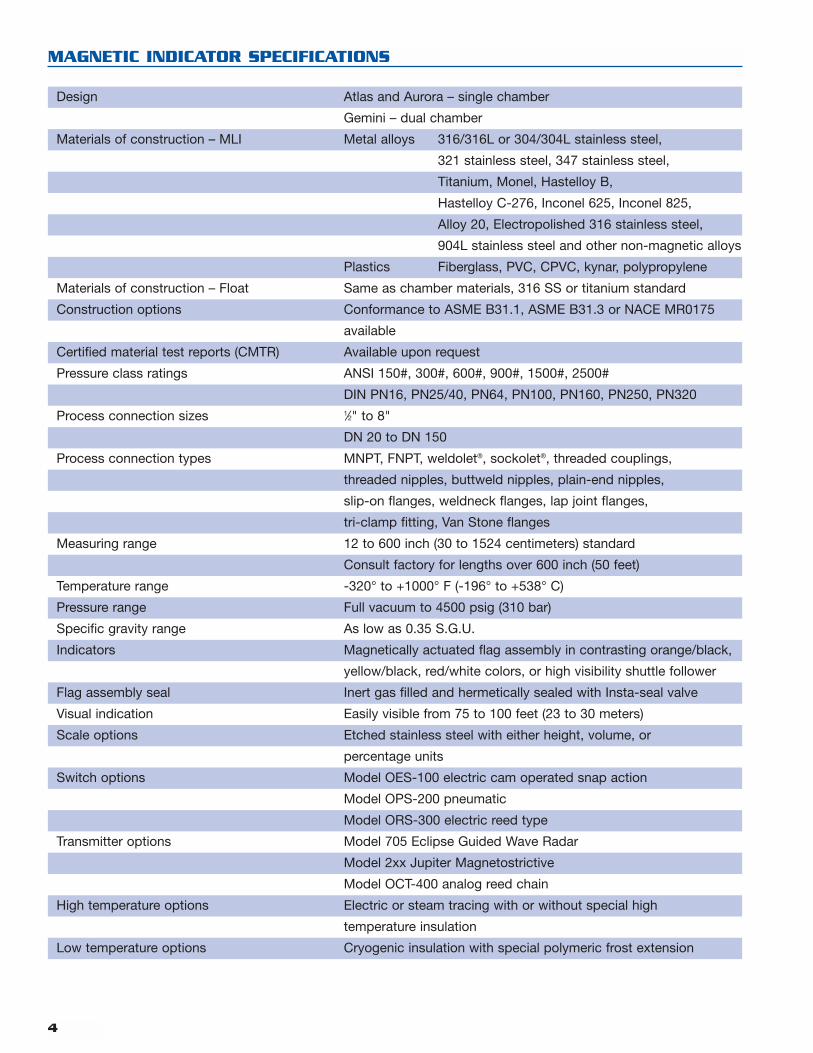
MAGNETIC INDICATOR SPECIFICATIONS
Design Atlas and Aurora – single chamber
Gemini – dual chamber
Materials of construction – MLI Metal alloys 316/316L or 304/304L stainless steel,
321 stainless steel, 347 stainless steel,
Titanium, Monel, Hastelloy B,
Hastelloy C-276, Inconel 625, Inconel 825,
Alloy 20, Electropolished 316 stainless steel,
904L stainless steel and other non-magnetic alloys
Plastics Fiberglass, PVC, CPVC, kynar, polypropylene
Materials of construction – Float Same as chamber materials, 316 SS or titanium standard
Construction options Conformance to ASME B31.1, ASME B31.3 or NACE MR0175
available
Certified material test reports (CMTR) Available upon request
Pressure class ratings ANSI 150#, 300#, 600#, 900#, 1500#, 2500#
DIN PN16, PN25/40, PN64, PN100, PN160, PN250, PN320
Process connection sizes 1⁄2" to 8"
DN 20 to DN 150
Process connection types MNPT, FNPT, weldolet®, sockolet®, threaded couplings,
threaded nipples, buttweld nipples, plain-end nipples,
slip-on flanges, weldneck flanges, lap joint flanges,
tri-clamp fitting, Van Stone flanges
Measuring range 12 to 600 inch (30 to 1524 centimeters) standard
Consult factory for lengths over 600 inch (50 feet)
Temperature range -320° to +1000° F (-196° to +538° C)
Pressure range Full vacuum to 4500 psig (310 bar)
Specific gravity range As low as 0.35 S.G.U.
Indicators Magnetically actuated flag assembly in contrasting orange/black,
yellow/black, red/white colors, or high visibility shuttle follower
Flag assembly seal Inert gas filled and hermetically sealed with Insta-seal valve
Visual indication Easily visible from 75 to 100 feet (23 to 30 meters)
Scale options Etched stainless steel with either height, volume, or
percentage units
Switch options Model OES-100 electric cam operated snap action
Model OPS-200 pneumatic
Model ORS-300 electric reed type
Transmitter options Model 705 Eclipse Guided Wave Radar
Model 2xx Jupiter Magnetostrictive
Model OCT-400 analog reed chain
High temperature options Electric or steam tracing with or without special high
temperature insulation
Low temperature options Cryogenic insulation with special polymeric frost extension
5
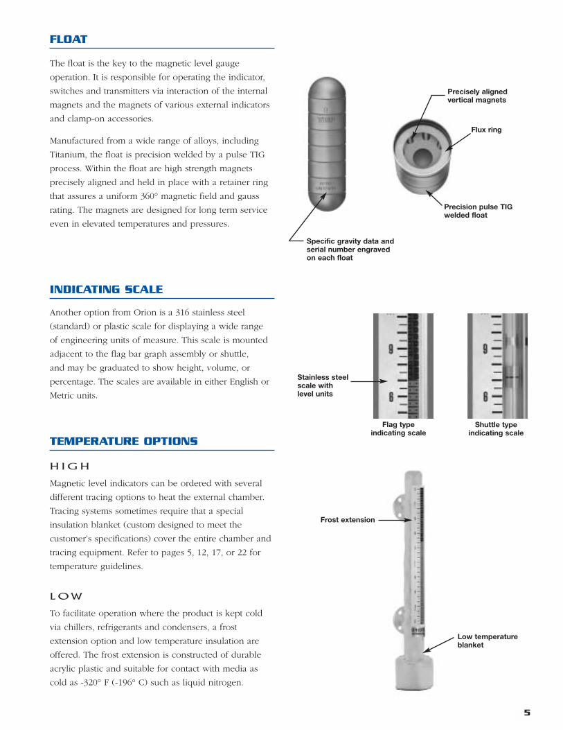
TEMPERATURE OPTIONS
H I G H
Magnetic level indicators can be ordered with several
different tracing options to heat the external chamber.
Tracing systems sometimes require that a special
insulation blanket (custom designed to meet the
customer’s specifications) cover the entire chamber and
tracing equipment. Refer to pages 5, 12, 17, or 22 for
temperature guidelines.
L O W
To facilitate operation where the product is kept cold
via chillers, refrigerants and condensers, a frost
extension option and low temperature insulation are
offered. The frost extension is constructed of durable
acrylic plastic and suitable for contact with media as
cold as -320° F (-196° C) such as liquid nitrogen.
INDICATING SCALE
Another option from Orion is a 316 stainless steel
(standard) or plastic scale for displaying a wide range
of engineering units of measure. This scale is mounted
adjacent to the flag bar graph assembly or shuttle,
and may be graduated to show height, volume, or
percentage. The scales are available in either English or
Metric units.
FLOAT
The float is the key to the magnetic level gauge
operation. It is responsible for operating the indicator,
switches and transmitters via interaction of the internal
magnets and the magnets of various external indicators
and clamp-on accessories.
Manufactured from a wide range of alloys, including
Titanium, the float is precision welded by a pulse TIG
process. Within the float are high strength magnets
precisely aligned and held in place with a retainer ring
that assures a uniform 360° magnetic field and gauss
rating. The magnets are designed for long term service
even in elevated temperatures and pressures.
Precisely alignedvertical magnets
Flux ring
Precision pulse TIGwelded float
Specific gravity data andserial number engravedon each float
Stainless steelscale withlevel units
Flag typeindicating scale
Frost extension
Low temperatureblanket
Shuttle typeindicating scale
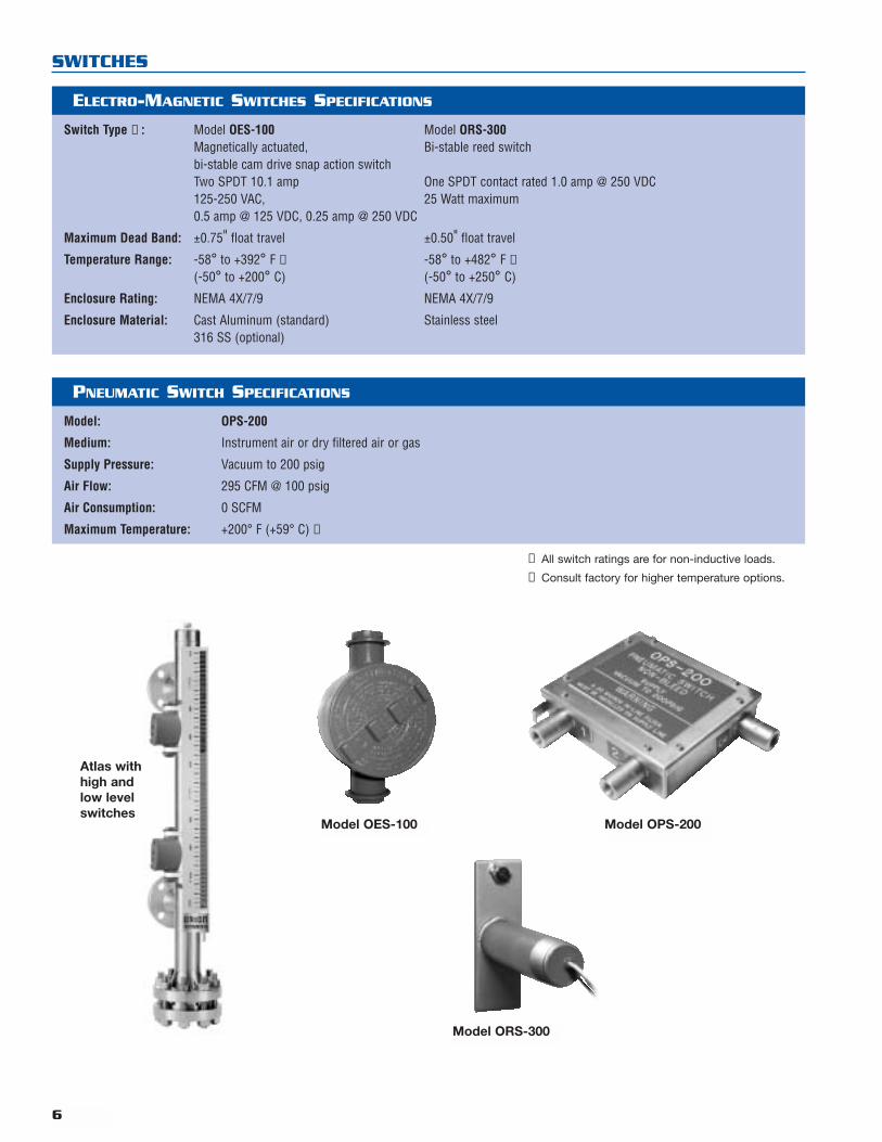
Atlas withhigh andlow levelswitches
6
Model OES-100 Model OPS-200
Model ORS-300
SWITCHES
ELECTRO-MAGNETIC SWITCHES SPECIFICATIONS
Switch Type ➀ : Model OES-100 Model ORS-300Magnetically actuated, Bi-stable reed switchbi-stable cam drive snap action switchTwo SPDT 10.1 amp One SPDT contact rated 1.0 amp @ 250 VDC125-250 VAC, 25 Watt maximum0.5 amp @ 125 VDC, 0.25 amp @ 250 VDC
Maximum Dead Band: ±0.75" float travel ±0.50" float travel
Temperature Range: -58° to +392° F ➁ -58° to +482° F ➁(-50° to +200° C) (-50° to +250° C)
Enclosure Rating: NEMA 4X/7/9 NEMA 4X/7/9
Enclosure Material: Cast Aluminum (standard) Stainless steel316 SS (optional)
PNEUMATIC SWITCH SPECIFICATIONS
Model: OPS-200
Medium: Instrument air or dry filtered air or gas
Supply Pressure: Vacuum to 200 psig
Air Flow: 295 CFM @ 100 psig
Air Consumption: 0 SCFM
Maximum Temperature: +200° F (+59° C) ➁
➀ All switch ratings are for non-inductive loads.
➁ Consult factory for higher temperature options.
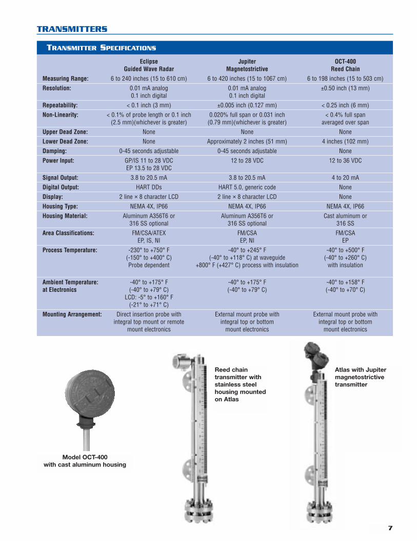
TRANSMITTERS
7
TRANSMITTER SPECIFICATIONS
Eclipse Jupiter OCT-400Guided Wave Radar Magnetostrictive Reed Chain
Measuring Range: 6 to 240 inches (15 to 610 cm) 6 to 420 inches (15 to 1067 cm) 6 to 198 inches (15 to 503 cm)
Resolution: 0.01 mA analog 0.01 mA analog ±0.50 inch (13 mm)0.1 inch digital 0.1 inch digital
Repeatability: < 0.1 inch (3 mm) ±0.005 inch (0.127 mm) < 0.25 inch (6 mm)
Non-Linearity: < 0.1% of probe length or 0.1 inch 0.020% full span or 0.031 inch < 0.4% full span(2.5 mm)(whichever is greater) (0.79 mm)(whichever is greater) averaged over span
Upper Dead Zone: None None None
Lower Dead Zone: None Approximately 2 inches (51 mm) 4 inches (102 mm)
Damping: 0-45 seconds adjustable 0-45 seconds adjustable None
Power Input: GP/IS 11 to 28 VDC 12 to 28 VDC 12 to 36 VDCEP 13.5 to 28 VDC
Signal Output: 3.8 to 20.5 mA 3.8 to 20.5 mA 4 to 20 mA
Digital Output: HART DDs HART 5.0, generic code None
Display: 2 line × 8 character LCD 2 line × 8 character LCD None
Housing Type: NEMA 4X, IP66 NEMA 4X, IP66 NEMA 4X, IP66
Housing Material: Aluminum A356T6 or Aluminum A356T6 or Cast aluminum or316 SS optional 316 SS optional 316 SS
Area Classifications: FM/CSA/ATEX FM/CSA FM/CSAEP, IS, NI EP, NI EP
Process Temperature: -230° to +750° F -40° to +245° F -40° to +500° F(-150° to +400° C) (-40° to +118° C) at waveguide (-40° to +260° C)Probe dependent +800° F (+427° C) process with insulation with insulation
Ambient Temperature: -40° to +175° F -40° to +175° F -40° to +158° Fat Electronics (-40° to +79° C) (-40° to +79° C) (-40° to +70° C)
LCD: -5° to +160° F (-21° to +71° C)
Mounting Arrangement: Direct insertion probe with External mount probe with External mount probe withintegral top mount or remote integral top or bottom integral top or bottom
mount electronics mount electronics mount electronics
Model OCT-400with cast aluminum housing
Reed chaintransmitter withstainless steelhousing mountedon Atlas
Atlas with Jupitermagnetostrictivetransmitter
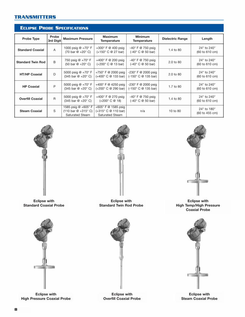
TRANSMITTERS
ECLIPSE PROBE SPECIFICATIONS
Probe TypeProbe
3rd DigitMaximum Pressure
MaximumTemperature
MinimumTemperature
Dielectric Range Length
Standard Coaxial A1000 psig @ +70° F(70 bar @ +20° C)
+300° F @ 400 psig(+150° C @ 27 bar)
-40° F @ 750 psig(-40° C @ 50 bar)
1.4 to 8024" to 240"
(60 to 610 cm)
Standard Twin Rod B750 psig @ +70° F(50 bar @ +20° C)
+400° F @ 200 psig(+200° C @ 13 bar)
-40° F @ 750 psig(-40° C @ 50 bar)
2.0 to 8024" to 240"
(60 to 610 cm)
HT/HP Coaxial D5000 psig @ +70° F(345 bar @ +20° C)
+750° F @ 2000 psig(+400° C @ 133 bar)
-230° F @ 2000 psig(-150° C @ 135 bar)
2.0 to 8024" to 240"
(60 to 610 cm)
HP Coaxial P5000 psig @ +70° F(345 bar @ +20° C)
+400° F @ 4250 psig(+200° C @ 290 bar)
-230° F @ 2000 psig(-150° C @ 135 bar)
1.7 to 8024" to 240"
(60 to 610 cm)
Overfill Coaxial R5000 psig @ +70° F(345 bar @ +20° C)
+400° F @ 270 psig(+200° C @ 18)
-40° F @ 750 psig(-40° C @ 50 bar)
1.4 to 8024" to 240"
(60 to 610 cm)
Steam Coaxial S1585 psig @ +605° F(110 bar @ +315° C)
Saturated Steam
+605° F @ 1585 psig(+315° C @ 110 bar)
Saturated Steamn/a 10 to 80
24" to 180"(60 to 455 cm)
8
Eclipse withStandard Coaxial Probe
Eclipse withStandard Twin Rod Probe
Eclipse withHigh Temp/High Pressure
Coaxial Probe
Eclipse withHigh Pressure Coaxial Probe
Eclipse withOverfill Coaxial Probe
Eclipse withSteam Coaxial Probe
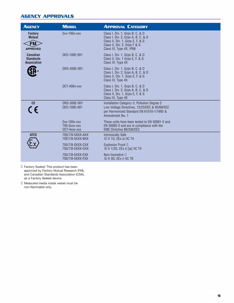
AGENCY APPROVALS
Factory 2xx-100x-xxx Class I, Div. 1, Grps B, C, & DMutual Class I, Div. 2, Grps A, B, C, & D
Class II, Div. 1, Grps E, F, & GClass II, Div. 2, Grps F & GClass III, Type 4X, IP66
Canadian OES-100E-001 Class I, Div. 1, Grps B, C, & DStandards Class II, Div. 1 Grps E, F, & G
Association Class III, Type 4X
ORS-300E-001 Class I, Div. 1, Grps B, C, & DClass I, Div. 2, Grps A, B, C, & DClass II, Div. 1, Grps E, F, & GClass III, Type 4X
OCT-400x-xxx Class I, Div. 1, Grps B, C, & DClass I, Div. 2, Grps A, B, C, & DClass II, Div. 1, Grps E, F, & GClass III, Type 4X
CE ORS-300E-001 Installation Category II, Pollution Degree 2OES-100E-001 Low Voltage Directives, 73/23/EEC & 93/68/EEC
per Harmonized Standard EN 61010-1/1993 &Amendment No. 1
2xx-100x-xxx These units have been tested to EN 50081-2 and705-5xxx-xxx EN 50082-2 and are in compliance with theOCT-4xxx-xxx EMC Directive 89/336/EEC
ATEX 705/7/8-5XXX-AXX Intrinsically Safe705/7/8-5XXX-BXX II 1G, EEx ia IIC T4
705/7/8-5XXX-CXX Explosion Proof ➀705/7/8-5XXX-DXX II 1/2G, EEx d [ia] IIC T4
705/7/8-5XXX-EXX Non-Incendive ➁705/7/8-5XXX-FXX II 3G, EEx n IIC T6
AGENCY MODEL APPROVAL CATEGORY
➀ Factory Sealed: This product has beenapproved by Factory Mutual Research (FM),and Canadian Standards Association (CSA),as a Factory Sealed device.
➁ Measured media inside vessel must benon-flammable only.
9
10
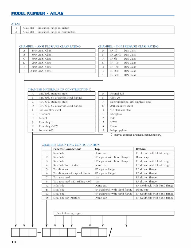
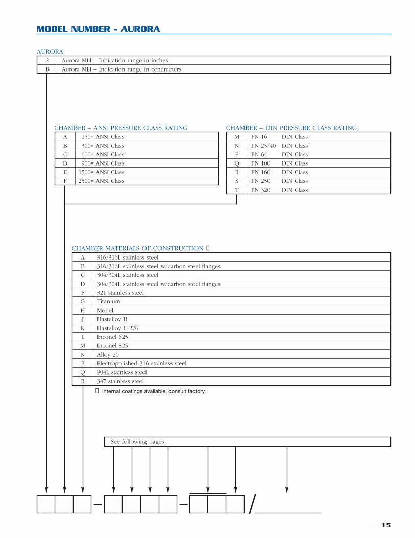
MODEL NUMBER - ATLAS
1 Atlas MLI – Indication range in inches
A Atlas MLI – Indication range in centimeters
ATLAS
See following pages
A 150# ANSI Class
B 300# ANSI Class
C 600# ANSI Class
D 900# ANSI Class
E 1500# ANSI Class
F 2500# ANSI Class
CHAMBER – ANSI PRESSURE CLASS RATINGM PN 16 DIN Class
N PN 25/40 DIN Class
P PN 64 DIN Class
Q PN 100 DIN Class
R PN 160 DIN Class
S PN 250 DIN Class
T PN 320 DIN Class
CHAMBER – DIN PRESSURE CLASS RATING
A 316/316L stainless steel
B 316/316L SS w/carbon steel flanges
C 304/304L stainless steel
D 304/304L SS w/carbon steel flanges
F 321 stainless steel
G Titanium
H Monel
J Hastelloy B
K Hastelloy C-276
L Inconel 625
CHAMBER MATERIALS OF CONSTRUCTION ➀M Inconel 825
N Alloy 20
P Electropolished 316 stainless steel
Q 904L stainless steel
R 347 stainless steel
1 Fiberglass
2 PVC
3 CPVC
4 Kynar
5 Polypropylene
Process Connections Top Bottom
1 Side/side Dome cap RF slip-on with blind flange
2 Side/side RF slip-on with blind flange Dome cap
3 Side/side RF slip-on with blind flange RF slip-on with blind flange
4 Side/side for interface Dome cap RF slip-on with blind flange
5 Top/bottom RF slip-on flange RF slip-on flange
6 Top/bottom with spool pieces RF slip-on flange RF slip-on flange
7 Top mounted n/a RF slip-on flange
8 Top mounted with stilling well n/a RF slip-on flange
A Side/side Dome cap RF weldneck with blind flange
B Side/side RF weldneck with blind flange Dome cap
C Side/side RF weldneck with blind flange RF weldneck with blind flange
D Side/side for interface Dome cap RF weldneck with blind flange
CHAMBER MOUNTING CONFIGURATION
➀ Internal coatings available, consult factory.
11
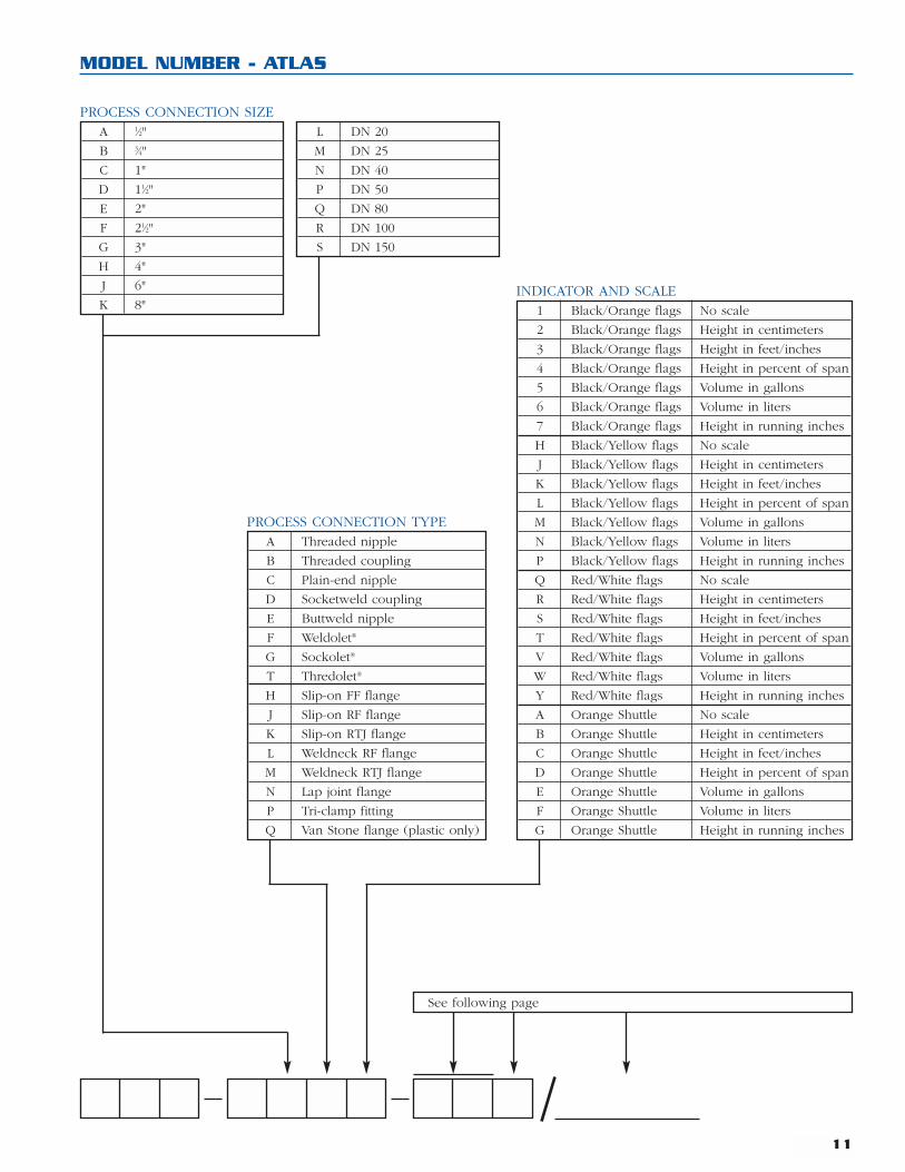
MODEL NUMBER - ATLAS
See following page
A 1⁄2"
B 3⁄4"
C 1"
D 11⁄2"
E 2"
F 21⁄2"
G 3"
H 4"
J 6"
K 8"
PROCESS CONNECTION SIZEL DN 20
M DN 25
N DN 40
P DN 50
Q DN 80
R DN 100
S DN 150
A Threaded nipple
B Threaded coupling
C Plain-end nipple
D Socketweld coupling
E Buttweld nipple
F Weldolet®
G Sockolet®
T Thredolet®
H Slip-on FF flange
J Slip-on RF flange
K Slip-on RTJ flange
L Weldneck RF flange
M Weldneck RTJ flange
N Lap joint flange
P Tri-clamp fitting
Q Van Stone flange (plastic only)
1 Black/Orange flags No scale
2 Black/Orange flags Height in centimeters
3 Black/Orange flags Height in feet/inches
4 Black/Orange flags Height in percent of span
5 Black/Orange flags Volume in gallons
6 Black/Orange flags Volume in liters
7 Black/Orange flags Height in running inches
H Black/Yellow flags No scale
J Black/Yellow flags Height in centimeters
K Black/Yellow flags Height in feet/inches
L Black/Yellow flags Height in percent of span
M Black/Yellow flags Volume in gallons
N Black/Yellow flags Volume in liters
P Black/Yellow flags Height in running inches
Q Red/White flags No scale
R Red/White flags Height in centimeters
S Red/White flags Height in feet/inches
T Red/White flags Height in percent of span
V Red/White flags Volume in gallons
W Red/White flags Volume in liters
Y Red/White flags Height in running inches
A Orange Shuttle No scale
B Orange Shuttle Height in centimeters
C Orange Shuttle Height in feet/inches
D Orange Shuttle Height in percent of span
E Orange Shuttle Volume in gallons
F Orange Shuttle Volume in liters
G Orange Shuttle Height in running inches
INDICATOR AND SCALE
PROCESS CONNECTION TYPE
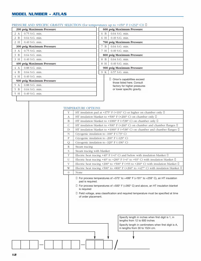
200 psig Maximum Pressure
2 A 0.75 S.G. min.
2 B 0.64 S.G. min.
2 H 0.49 S.G. min.
300 psig Maximum Pressure
3 A 0.75 S.G. min.
3 B 0.64 S.G. min.
3 H 0.49 S.G. min.
400 psig Maximum Pressure
4 A 0.88 S.G. min.
4 B 0.64 S.G. min.
4 H 0.49 S.G. min.
500 psig Maximum Pressure
5 A 0.88 S.G. min.
5 B 0.64 S.G. min.
5 H 0.49 S.G. min.
600 psig Maximum Pressure
6 B 0.64 S.G. min.
6 H 0.49 S.G. min.
700 psig Maximum Pressure
7 B 0.64 S.G. min.
7 H 0.49 S.G. min.
800 psig Maximum Pressure
8 B 0.64 S.G. min.
8 H 0.49 S.G. min.
900 psig Maximum Pressure
9 K 0.57 S.G. min.
Y HT insulation pad at +375° F (+191° C) or higher on chamber only ➁
A HT insulation blanket to +500° F (+260° C) on chamber only ➂
B HT insulation blanket to +1000° F (+538° C) on chamber only ➂
C HT insulation blanket to +500° F (+260° C) on chamber and chamber flanges ➂
D HT insulation blanket to +1000° F (+538° C) on chamber and chamber flanges ➂
N Cryogenic insulation to -100° F (-73° C)
P Cryogenic insulation to -200° F (-129° C)
Q Cryogenic insulation to -320° F (-196° C)
R Steam tracing
S Steam tracing with blanket
T Electric heat tracing +40° F (+4° C) and below with insulation blanket ➃
U Electric heat tracing +40° to +200° F (+4° to +93° C) with insulation blanket ➃
V Electric heat tracing +200° to +500° F (+93 to +260° C) with insulation blanket ➃
W Electric heat tracing +500° to +800° F (+260° to +427° C) with insulation blanket ➃
0 None
TEMPERATURE OPTIONS
12
MODEL NUMBER - ATLAS
➁ For process temperatures of +375° to +499° F (+191° to +259° C), an HT insulationpad is required.
➂ For process temperatures of +500° F (+260° C) and above, an HT insulation blanketis required
➃ Field voltage, area classification and required temperature must be specified at timeof order placement.
Specify length in inches when first digit is 1, inlengths from 12 to 600 inches
Specify length in centimeters when first digit is A,in lengths from 30 to 1524 cm.
➀ Orion’s capabilities exceedthose listed here. Consultfactory for higher pressuresor lower specific gravity.
PRESSURE AND SPECIFIC GRAVITY SELECTION (for temperatures up to +450° F (+232° C)) ➀
13
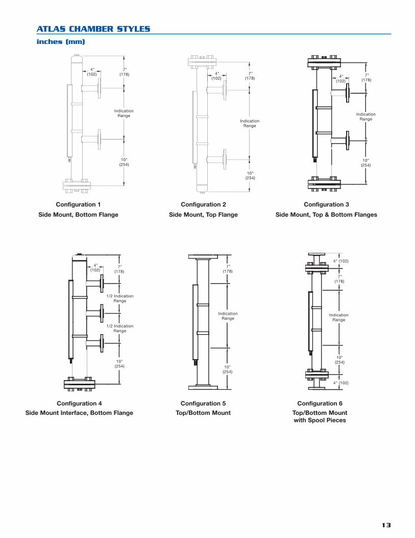
ATLAS CHAMBER STYLES
inches (mm)
IndicationRange
7"(178)
4"(102)
10"(254)
7"(178)
4"(102)
10"(254)
IndicationRange
IndicationRange
7"(178)
4"(102)
10"(254)
Configuration 1
Side Mount, Bottom Flange
Configuration 2
Side Mount, Top Flange
Configuration 3
Side Mount, Top & Bottom Flanges
Configuration 4
Side Mount Interface, Bottom Flange
Configuration 5
Top/Bottom Mount
Configuration 6
Top/Bottom Mountwith Spool Pieces
1/2 IndicationRange
1/2 IndicationRange
7"(178)
4"(102)
10"(254)
IndicationRange
7"(178)
10"(254)
IndicationRange
7"(178)
4" (102)
4" (102)
10"(254)
14
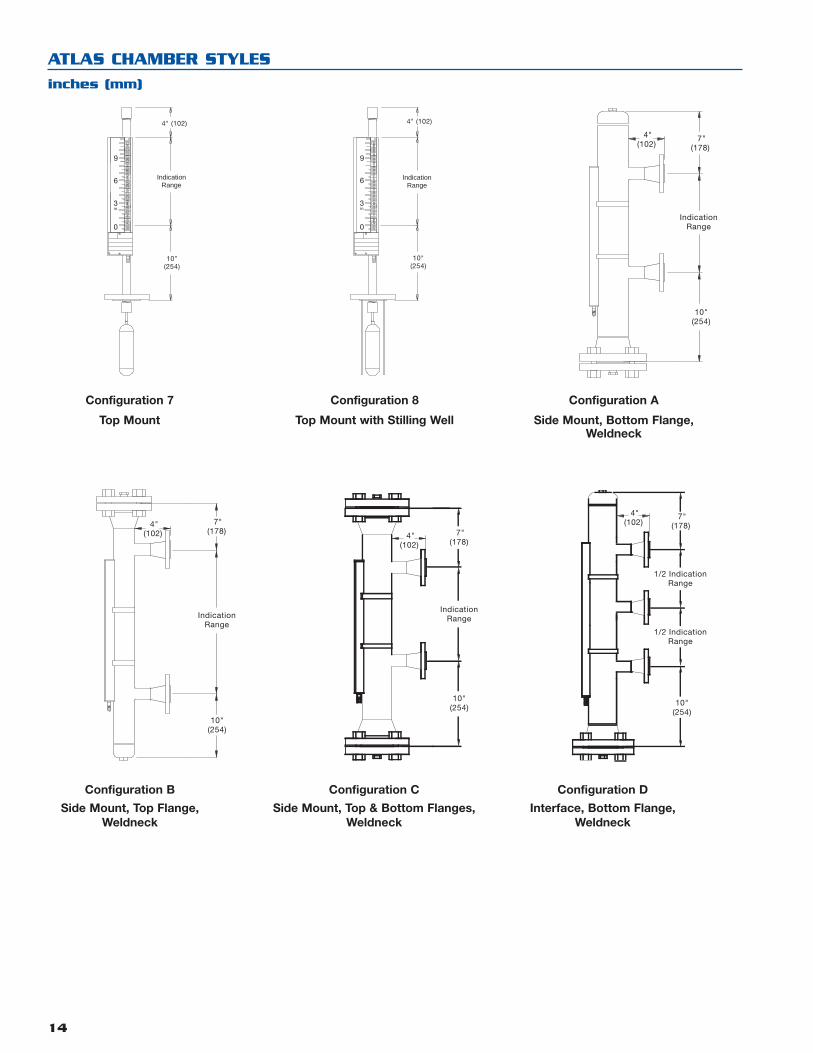
ATLAS CHAMBER STYLES
inches (mm)
IndicationRange
7"(178)
4"(102)
10"(254)
9
3
6
in.
0
IndicationRange
4" (102)
10"(254)
9
3
6
in.
0
IndicationRange
4" (102)
10"(254)
Configuration 7
Top Mount
Configuration 8
Top Mount with Stilling Well
Configuration A
Side Mount, Bottom Flange,Weldneck
Configuration B
Side Mount, Top Flange,Weldneck
Configuration C
Side Mount, Top & Bottom Flanges,Weldneck
Configuration D
Interface, Bottom Flange,Weldneck
IndicationRange
7"(178)
4"(102)
10"(254)
IndicationRange
7"(178)
4"(102)
10"(254)
1/2 IndicationRange
1/2 IndicationRange
7"(178)
4"(102)
10"(254)
15
MODEL NUMBER - AURORA
2 Aurora MLI – Indication range in inches
B Aurora MLI – Indication range in centimeters
AURORA
A 150# ANSI Class
B 300# ANSI Class
C 600# ANSI Class
D 900# ANSI Class
E 1500# ANSI Class
F 2500# ANSI Class
CHAMBER – ANSI PRESSURE CLASS RATINGM PN 16 DIN Class
N PN 25/40 DIN Class
P PN 64 DIN Class
Q PN 100 DIN Class
R PN 160 DIN Class
S PN 250 DIN Class
T PN 320 DIN Class
CHAMBER – DIN PRESSURE CLASS RATING
A 316/316L stainless steel
B 316/316L stainless steel w/carbon steel flanges
C 304/304L stainless steel
D 304/304L stainless steel w/carbon steel flanges
F 321 stainless steel
G Titanium
H Monel
J Hastelloy B
K Hastelloy C-276
L Inconel 625
M Inconel 825
N Alloy 20
P Electropolished 316 stainless steel
Q 904L stainless steel
R 347 stainless steel
CHAMBER MATERIALS OF CONSTRUCTION ➀
See following pages
➀ Internal coatings available, consult factory.
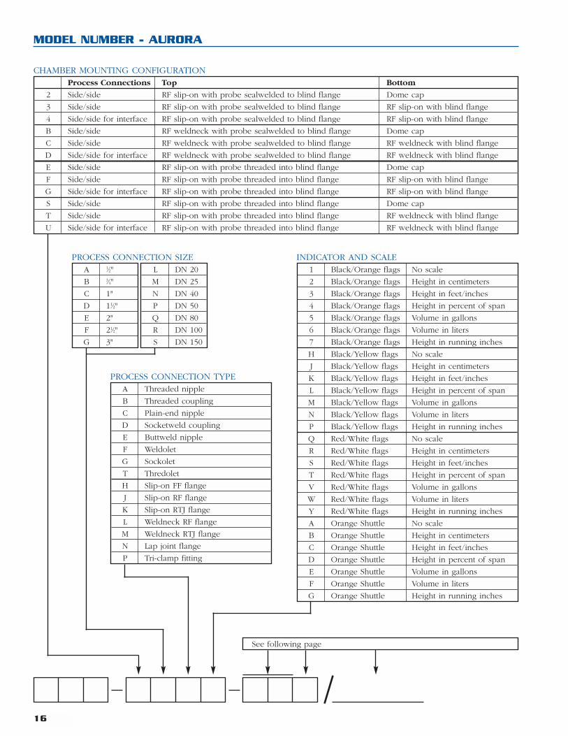
Process Connections Top Bottom
2 Side/side RF slip-on with probe sealwelded to blind flange Dome cap
3 Side/side RF slip-on with probe sealwelded to blind flange RF slip-on with blind flange
4 Side/side for interface RF slip-on with probe sealwelded to blind flange RF slip-on with blind flange
B Side/side RF weldneck with probe sealwelded to blind flange Dome cap
C Side/side RF weldneck with probe sealwelded to blind flange RF weldneck with blind flange
D Side/side for interface RF weldneck with probe sealwelded to blind flange RF weldneck with blind flange
E Side/side RF slip-on with probe threaded into blind flange Dome cap
F Side/side RF slip-on with probe threaded into blind flange RF slip-on with blind flange
G Side/side for interface RF slip-on with probe threaded into blind flange RF slip-on with blind flange
S Side/side RF slip-on with probe threaded into blind flange Dome cap
T Side/side RF slip-on with probe threaded into blind flange RF weldneck with blind flange
U Side/side for interface RF slip-on with probe threaded into blind flange RF weldneck with blind flange
CHAMBER MOUNTING CONFIGURATION
A 1⁄2"
B 3⁄4"
C 1"
D 11⁄2"
E 2"
F 21⁄2"
G 3"
L DN 20
M DN 25
N DN 40
P DN 50
Q DN 80
R DN 100
S DN 150
A Threaded nipple
B Threaded coupling
C Plain-end nipple
D Socketweld coupling
E Buttweld nipple
F Weldolet
G Sockolet
T Thredolet
H Slip-on FF flange
J Slip-on RF flange
K Slip-on RTJ flange
L Weldneck RF flange
M Weldneck RTJ flange
N Lap joint flange
P Tri-clamp fitting
PROCESS CONNECTION TYPE
16
MODEL NUMBER - AURORA
See following page
1 Black/Orange flags No scale
2 Black/Orange flags Height in centimeters
3 Black/Orange flags Height in feet/inches
4 Black/Orange flags Height in percent of span
5 Black/Orange flags Volume in gallons
6 Black/Orange flags Volume in liters
7 Black/Orange flags Height in running inches
H Black/Yellow flags No scale
J Black/Yellow flags Height in centimeters
K Black/Yellow flags Height in feet/inches
L Black/Yellow flags Height in percent of span
M Black/Yellow flags Volume in gallons
N Black/Yellow flags Volume in liters
P Black/Yellow flags Height in running inches
Q Red/White flags No scale
R Red/White flags Height in centimeters
S Red/White flags Height in feet/inches
T Red/White flags Height in percent of span
V Red/White flags Volume in gallons
W Red/White flags Volume in liters
Y Red/White flags Height in running inches
A Orange Shuttle No scale
B Orange Shuttle Height in centimeters
C Orange Shuttle Height in feet/inches
D Orange Shuttle Height in percent of span
E Orange Shuttle Volume in gallons
F Orange Shuttle Volume in liters
G Orange Shuttle Height in running inches
INDICATOR AND SCALEPROCESS CONNECTION SIZE

17
200 psig Maximum Pressure
2 A 0.75 S.G. min.
2 B 0.64 S.G. min.
2 H 0.49 S.G. min.
300 psig Maximum Pressure
3 A 0.75 S.G. min.
3 B 0.64 S.G. min.
3 H 0.49 S.G. min.
400 psig Maximum Pressure
4 A 0.88 S.G. min.
4 B 0.64 S.G. min.
4 H 0.49 S.G. min.
450 psig Maximum Pressure
5 A 0.88 S.G. min.
5 B 0.64 S.G. min.
5 H 0.49 S.G. min.
500 psig Maximum Pressure
5 A 0.88 S.G. min.
5 B 0.64 S.G. min.
5 K 0.49 S.G. min.
550 psig Maximum Pressure
6 B 0.64 S.G. min.
600 psig Maximum Pressure
6 K 0.49 S.G. min.
700 psig Maximum Pressure
7 K 0.49 S.G. min.
775 psig Maximum Pressure
8 K 0.49 S.G. min.
MODEL NUMBER - AURORA
Specify length in inches when first digit is 1, inlengths from 12 to 600 inches
Specify length in centimeters when first digit is A,in lengths from 30 to 1524 cm.
➀ Orion’s capabilities exceedthose listed here. Consultfactory for higher pressuresor lower specific gravity.
Y HT insulation pad at +375° F (+191° C) or higher on chamber only ➁
A HT insulation blanket to +500° F (+260° C) on chamber only ➂
B HT insulation blanket to +1000° F (+538° C) on chamber only ➂
C HT insulation blanket to +500° F (+260° C) on chamber and flanges ➂
D HT insulation blanket to +1000° F (+538° C) on chamber and flanges ➂
N Cryogenic insulation to -100° F (-73° C)
P Cryogenic insulation to -200° F (-129° C)
Q Cryogenic insulation to -320° F (-196° C)
R Steam tracing
S Steam tracing with blanket
T Electric heat tracing +40° F (+4° C) and below with insulation blanket ➃
U Electric heat tracing +40° to +200° F (+4° to +93° C) with insulation blanket ➃
V Electric heat tracing +200° to +500° F (+93 to +260° C) with insulation blanket ➃
W Electric heat tracing +500° to +800° F (+260° to +427° C) with insulation blanket ➃
0 None
TEMPERATURE OPTIONS
➁ For process temperatures of +375° to +499° F (+191° to +259° C), an HT insulationpad is required.
➂ For process temperatures of +500° F (+260° C) and above, an HT insulation blanketis required
➃ Field voltage, area classification and required temperature must be specified at timeof order placement.
PRESSURE AND SPECIFIC GRAVITY SELECTION (for temperatures up to +450° F (+232° C)) ➀
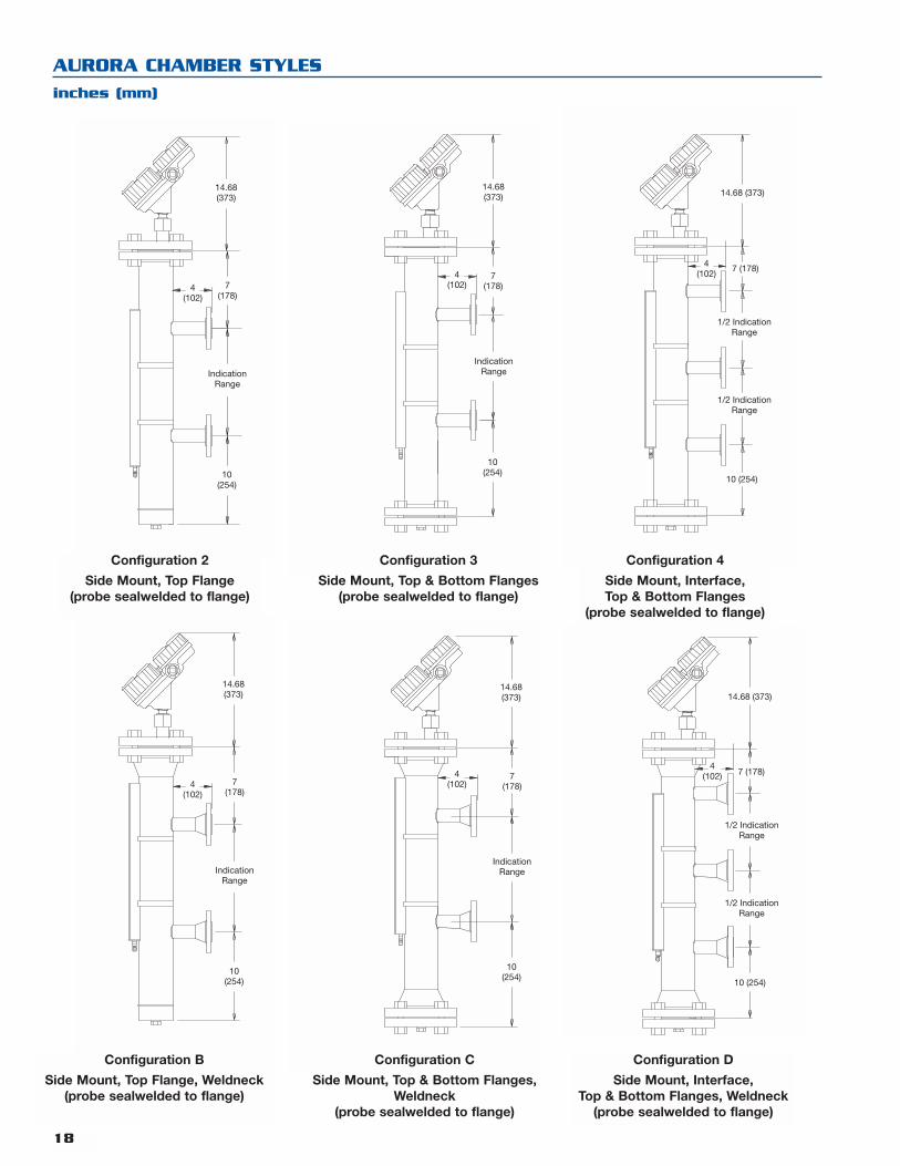
18
AURORA CHAMBER STYLES
inches (mm)
IndicationRange
14.68(373)
7(178)
10(254)
4(102)
Configuration 2
Side Mount, Top Flange(probe sealwelded to flange)
14.68 (373)
10 (254)
7 (178)4(102)
1/2 IndicationRange
1/2 IndicationRange
Configuration 4
Side Mount, Interface,Top & Bottom Flanges
(probe sealwelded to flange)
14.68(373)
7(178)
10(254)
4(102)
IndicationRange
Configuration 3
Side Mount, Top & Bottom Flanges(probe sealwelded to flange)
IndicationRange
14.68(373)
7(178)
10(254)
4(102)
Configuration B
Side Mount, Top Flange, Weldneck(probe sealwelded to flange)
14.68 (373)
4(102)
10 (254)
7 (178)
1/2 IndicationRange
1/2 IndicationRange
Configuration D
Side Mount, Interface,Top & Bottom Flanges, Weldneck
(probe sealwelded to flange)
IndicationRange
14.68(373)
7(178)
10(254)
4(102)
Configuration C
Side Mount, Top & Bottom Flanges,Weldneck
(probe sealwelded to flange)
19
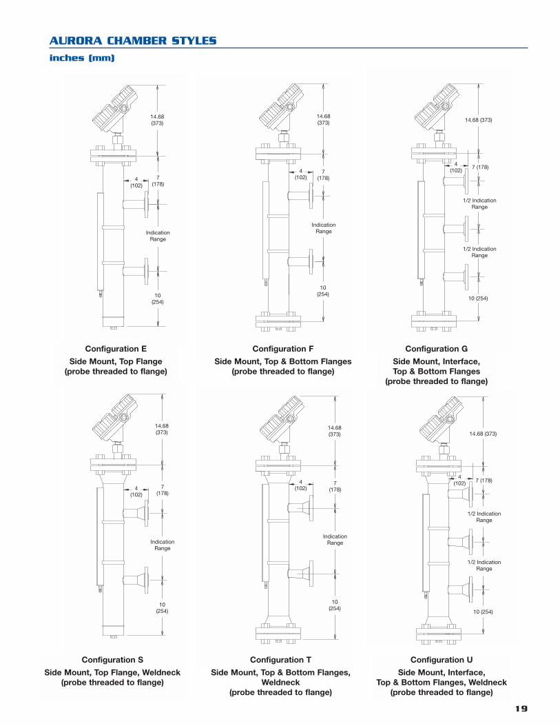
AURORA CHAMBER STYLES
inches (mm)
IndicationRange
14.68(373)
7(178)
10(254)
4(102)
Configuration E
Side Mount, Top Flange(probe threaded to flange)
14.68 (373)
10 (254)
7 (178)4(102)
1/2 IndicationRange
1/2 IndicationRange
Configuration G
Side Mount, Interface,Top & Bottom Flanges
(probe threaded to flange)
14.68(373)
7(178)
10(254)
4(102)
IndicationRange
Configuration F
Side Mount, Top & Bottom Flanges(probe threaded to flange)
IndicationRange
14.68(373)
7(178)
10(254)
4(102)
Configuration S
Side Mount, Top Flange, Weldneck(probe threaded to flange)
14.68 (373)
4(102)
10 (254)
7 (178)
1/2 IndicationRange
1/2 IndicationRange
Configuration U
Side Mount, Interface,Top & Bottom Flanges, Weldneck
(probe threaded to flange)
IndicationRange
14.68(373)
7(178)
10(254)
4(102)
Configuration T
Side Mount, Top & Bottom Flanges,Weldneck
(probe threaded to flange)

20
MODEL NUMBER - GEMINI
3 Gemini MLI – Indication range in inches
C Gemini MLI – Indication range in centimeters
GEMINI
A 150# ANSI Class
B 300# ANSI Class
C 600# ANSI Class
D 900# ANSI Class
E 1500# ANSI Class
F 2500# ANSI Class
CHAMBER – ANSI PRESSURE CLASS RATING ➀M PN 16 DIN Class
N PN 25/40 DIN Class
P PN 64 DIN Class
Q PN 100 DIN Class
R PN 160 DIN Class
S PN 250 DIN Class
T PN 320 DIN Class
CHAMBER – DIN PRESSURE CLASS RATING
Process Connections Top Bottom Secondary Chamber
1 Side/side Dome cap RF slip-on with blind flange Dome cap Dome cap
2 Side/side RF slip-on with blind flange Dome cap Dome cap Dome cap
3 Side/side RF slip-on with blind flange RF slip-on with blind flange Dome cap Dome cap
4 Side/side for interface Dome cap RF slip-on with blind flange Dome cap Dome cap
5 Top/bottom RF slip-on flange RF slip-on flange Dome cap Dome cap
6 Top/bottom w/spool pcs. RF slip-on flange RF slip-on flange Dome cap Dome cap
A Side/side Dome cap RF weldneck with blind flange Dome cap Dome cap
B Side/side RF weldneck with blind flange Dome cap Dome cap Dome cap
C Side/side RF weldneck with blind flange RF weldneck with blind flange Dome cap Dome cap
D Side/side for interface Dome cap RF weldneck with blind flange Dome cap Dome cap
J Side/side Dome cap RF slip-on with blind flange RF slip-on flange Dome cap
K Side/side RF slip-on with blind flange Dome cap RF slip-on flange Dome cap
L Side/side RF slip-on with blind flange RF slip-on with blind flange RF slip-on flange Dome cap
M Top/bottom RF slip-on flange RF slip-on flange RF slip-on flange Dome cap
N Top/bottom w/spool pcs. RF slip-on flange RF slip-on flange RF slip-on flange Dome cap
P Side/side Dome cap RF weldneck with blind flange RF weldneck flange Dome cap
Q Side/side RF weldneck with blind flange Dome cap RF weldneck flange Dome cap
R Side/side RF weldneck with blind flange RF weldneck with blind flange RF weldneck flange Dome cap
CHAMBER MOUNTING CONFIGURATION
A 316/316L stainless steel
B 316/316L SS w/carbon steel flanges
C 304/304L stainless steel
D 304/304L SS w/carbon steel flanges
F 321 stainless steel
G Titanium
H Monel
J Hastelloy B
CHAMBER MATERIALS OF CONSTRUCTION ➀K Hastelloy C-276
L Inconel 625
M Inconel 825
N Alloy 20
P Electropolished 316 stainless steel
Q 904L stainless steel
R 347 stainless steel
See following pages
➀ Internal coatings available, consult factory.
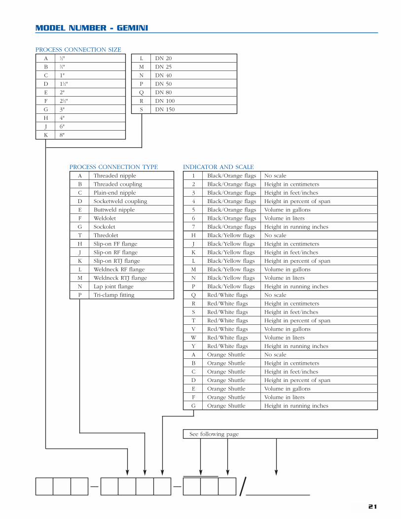
21
MODEL NUMBER - GEMINI
A 1⁄2"
B 3⁄4"
C 1"
D 11⁄2"
E 2"
F 21⁄2"
G 3"
H 4"
J 6"
K 8"
PROCESS CONNECTION SIZEL DN 20
M DN 25
N DN 40
P DN 50
Q DN 80
R DN 100
S DN 150
A Threaded nipple
B Threaded coupling
C Plain-end nipple
D Socketweld coupling
E Buttweld nipple
F Weldolet
G Sockolet
T Thredolet
H Slip-on FF flange
J Slip-on RF flange
K Slip-on RTJ flange
L Weldneck RF flange
M Weldneck RTJ flange
N Lap joint flange
P Tri-clamp fitting
PROCESS CONNECTION TYPE1 Black/Orange flags No scale
2 Black/Orange flags Height in centimeters
3 Black/Orange flags Height in feet/inches
4 Black/Orange flags Height in percent of span
5 Black/Orange flags Volume in gallons
6 Black/Orange flags Volume in liters
7 Black/Orange flags Height in running inches
H Black/Yellow flags No scale
J Black/Yellow flags Height in centimeters
K Black/Yellow flags Height in feet/inches
L Black/Yellow flags Height in percent of span
M Black/Yellow flags Volume in gallons
N Black/Yellow flags Volume in liters
P Black/Yellow flags Height in running inches
Q Red/White flags No scale
R Red/White flags Height in centimeters
S Red/White flags Height in feet/inches
T Red/White flags Height in percent of span
V Red/White flags Volume in gallons
W Red/White flags Volume in liters
Y Red/White flags Height in running inches
A Orange Shuttle No scale
B Orange Shuttle Height in centimeters
C Orange Shuttle Height in feet/inches
D Orange Shuttle Height in percent of span
E Orange Shuttle Volume in gallons
F Orange Shuttle Volume in liters
G Orange Shuttle Height in running inches
INDICATOR AND SCALE
See following page
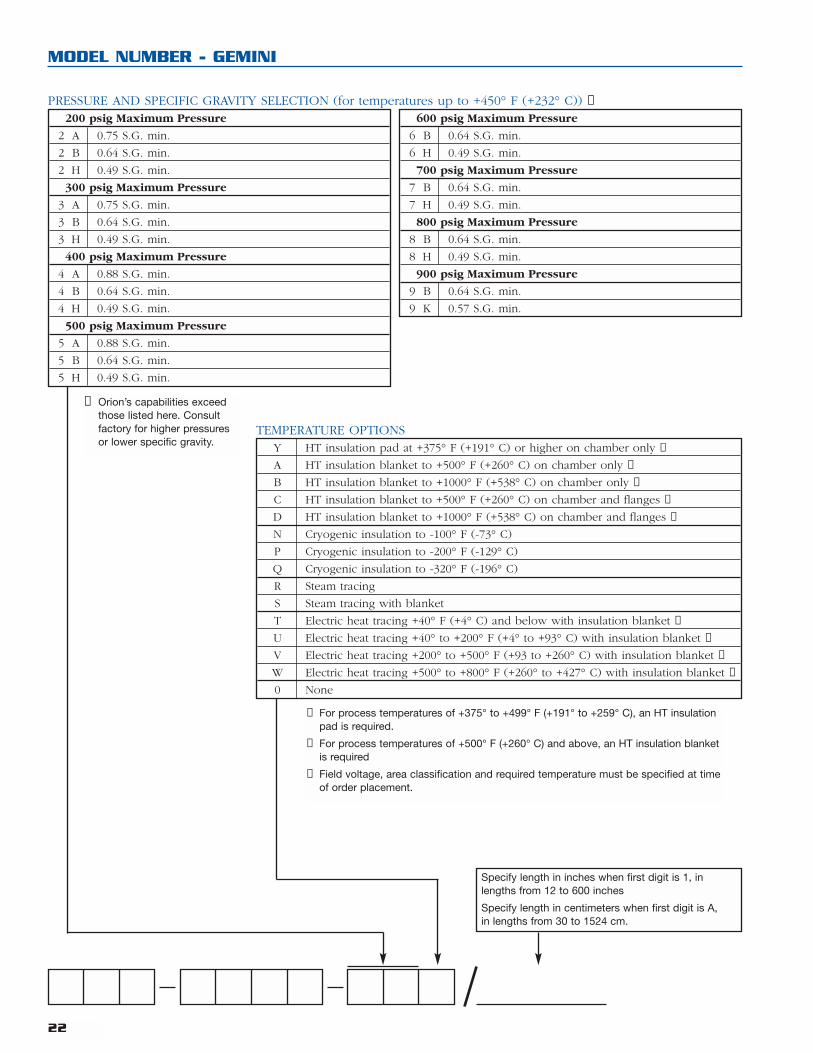
22
MODEL NUMBER - GEMINI
600 psig Maximum Pressure
6 B 0.64 S.G. min.
6 H 0.49 S.G. min.
700 psig Maximum Pressure
7 B 0.64 S.G. min.
7 H 0.49 S.G. min.
800 psig Maximum Pressure
8 B 0.64 S.G. min.
8 H 0.49 S.G. min.
900 psig Maximum Pressure
9 B 0.64 S.G. min.
9 K 0.57 S.G. min.
➀ Orion’s capabilities exceedthose listed here. Consultfactory for higher pressuresor lower specific gravity.
Specify length in inches when first digit is 1, inlengths from 12 to 600 inches
Specify length in centimeters when first digit is A,in lengths from 30 to 1524 cm.
Y HT insulation pad at +375° F (+191° C) or higher on chamber only ➁
A HT insulation blanket to +500° F (+260° C) on chamber only ➂
B HT insulation blanket to +1000° F (+538° C) on chamber only ➂
C HT insulation blanket to +500° F (+260° C) on chamber and flanges ➂
D HT insulation blanket to +1000° F (+538° C) on chamber and flanges ➂
N Cryogenic insulation to -100° F (-73° C)
P Cryogenic insulation to -200° F (-129° C)
Q Cryogenic insulation to -320° F (-196° C)
R Steam tracing
S Steam tracing with blanket
T Electric heat tracing +40° F (+4° C) and below with insulation blanket ➃
U Electric heat tracing +40° to +200° F (+4° to +93° C) with insulation blanket ➃
V Electric heat tracing +200° to +500° F (+93 to +260° C) with insulation blanket ➃
W Electric heat tracing +500° to +800° F (+260° to +427° C) with insulation blanket ➃
0 None
TEMPERATURE OPTIONS
➁ For process temperatures of +375° to +499° F (+191° to +259° C), an HT insulationpad is required.
➂ For process temperatures of +500° F (+260° C) and above, an HT insulation blanketis required
➃ Field voltage, area classification and required temperature must be specified at timeof order placement.
200 psig Maximum Pressure
2 A 0.75 S.G. min.
2 B 0.64 S.G. min.
2 H 0.49 S.G. min.
300 psig Maximum Pressure
3 A 0.75 S.G. min.
3 B 0.64 S.G. min.
3 H 0.49 S.G. min.
400 psig Maximum Pressure
4 A 0.88 S.G. min.
4 B 0.64 S.G. min.
4 H 0.49 S.G. min.
500 psig Maximum Pressure
5 A 0.88 S.G. min.
5 B 0.64 S.G. min.
5 H 0.49 S.G. min.
PRESSURE AND SPECIFIC GRAVITY SELECTION (for temperatures up to +450° F (+232° C)) ➀
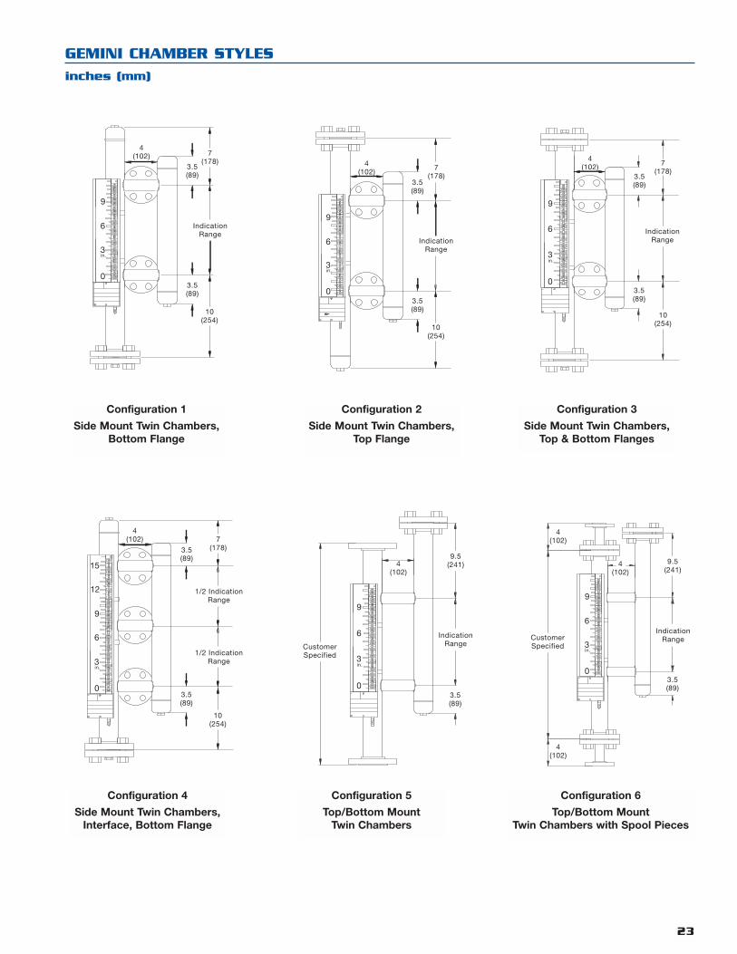
23
GEMINI CHAMBER STYLES
inches (mm)
1/2 IndicationRange
1/2 IndicationRange
10(254)
7(178)3.5
(89)
3.5(89)
4(102)
9
3
6
in.
0
15
12
CustomerSpecified
9
3
6
in.
0
4(102)
3.5(89)
9.5(241)
IndicationRange
Configuration 4
Side Mount Twin Chambers,Interface, Bottom Flange
Configuration 5
Top/Bottom MountTwin Chambers
9.5(241)
3.5(89)
9
3
6
in.
0
CustomerSpecified
4(102)
4(102)
4(102)
IndicationRange
Configuration 6
Top/Bottom MountTwin Chambers with Spool Pieces
10(254)
IndicationRange
7(178)
3.5(89)
3.5(89)
9
3
6
in.
0
4(102)
9
3
6
in.
0
IndicationRange
10(254)
7(178)
3.5(89)
3.5(89)
4(102)
Configuration 1
Side Mount Twin Chambers,Bottom Flange
Configuration 2
Side Mount Twin Chambers,Top Flange
9
3
6
in.
0
IndicationRange
10(254)
7(178)
3.5(89)
3.5(89)
4(102)
Configuration 3
Side Mount Twin Chambers,Top & Bottom Flanges
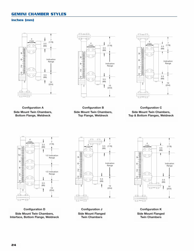
24
GEMINI CHAMBER STYLES
inches (mm)
10(254)
7(178)3.5
(89)
3.5(89)
4(102)
1/2 IndicationRange
1/2 IndicationRange
9
3
6
in.
0
15
129
3
6
in.
0
10(254)
7(178)3.5
(89)
3.5(89)
4(102)
IndicationRange
Configuration D
Side Mount Twin Chambers,Interface, Bottom Flange, Weldneck
Configuration J
Side Mount FlangedTwin Chambers
9
3
6
in.
0
10(254)
7(178)
3.5(89)
3.5(89)
4(102)
IndicationRange
Configuration K
Side Mount FlangedTwin Chambers
IndicationRange
9
3
6
in.
0
10(254)
7(178)
3.5(89)
3.5(89)
4(102)
9
3
6
in.
0
10(254)
7(178)
3.5(89)
3.5(89)
4(102)
IndicationRange
Configuration A
Side Mount Twin Chambers,Bottom Flange, Weldneck
Configuration B
Side Mount Twin Chambers,Top Flange, Weldneck
9
3
6
in.
0
10(254)
7(178)
3.5(89)
3.5(89)
4(102)
IndicationRange
Configuration C
Side Mount Twin Chambers,Top & Bottom Flanges, Weldneck
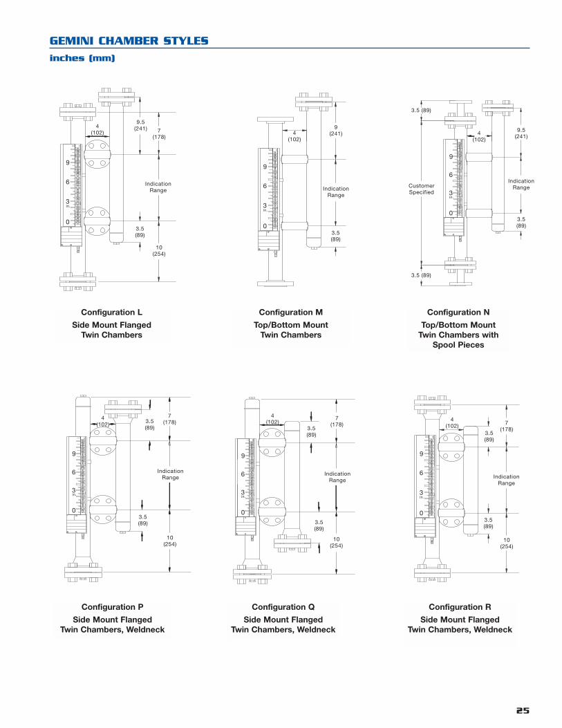
25
GEMINI CHAMBER STYLES
inches (mm)
9
3
6
in.
0
10(254)
7(178)3.5
(89)
3.5(89)
4(102)
IndicationRange
9
3
6
in.
0
10(254)
7(178)
3.5(89)
3.5(89)
4(102)
IndicationRange
Configuration P
Side Mount FlangedTwin Chambers, Weldneck
Configuration Q
Side Mount FlangedTwin Chambers, Weldneck
9
3
6
in.
0
IndicationRange
10(254)
7(178)
3.5(89)
3.5(89)
4(102)
Configuration R
Side Mount FlangedTwin Chambers, Weldneck
IndicationRange
9.5(241)
9
3
6
in.
0
10(254)
7(178)
3.5(89)
4(102)
9
3
6
in.
0
9(241)
IndicationRange
3.5(89)
4(102)
Configuration L
Side Mount FlangedTwin Chambers
Configuration M
Top/Bottom MountTwin Chambers
CustomerSpecified
9.5(241)
IndicationRange
9
3
6
in.
03.5(89)
3.5 (89)
3.5 (89)
4(102)
Configuration N
Top/Bottom MountTwin Chambers with
Spool Pieces

MODEL NUMBER - ACCESSORIES
AURORA ECLIPSE TRANSMITTER
0 4-20 mA
1 4-20 mA with HART
OUTPUT
1 English
2 Spanish
3 French
4 German
MENU LANGUAGE
0 None
A Digital display and keypad
DISPLAY AND KEYPAD
1 Integral, GP, IS & NI, FM/CSA
2 Remote, GP, IS & NI, FM/CSA
3 Integral, EP & NI, FM/CSA
4 Remote, EP & NI, FM/CSA
A Integral, GP & IS, ATEX Exia
B Remote, GP & IS, ATEX Exia
C Integral, EP, ATEX Exd
D Remote, EP, ATEX Exd
E Integral, NI, ATEX Exn
F Remote, NI, ATEX Exn
TRANSMITTER MOUNTING AND APPROVALS
1 Cast aluminum
2 316 stainless steel
HOUSING MATERIAL
0 3⁄4" NPT
1 M20
2 PG 13.5
3 PG 16
CONDUIT ENTRY
7 0 5 5
26
Eclipse withstandard coaxial probe
* Probe length specified should be indicationrange of MLI plus 13 inches (33 cm)
ProbeInsertionLength
MountingFlange
45°
4.12(105)
Elect.Conn.Qty. 2
3.27(83)
4.00(102)
10.08(256)
2.33(59)
1/2" NPTPlugged Vent
(standard)
*
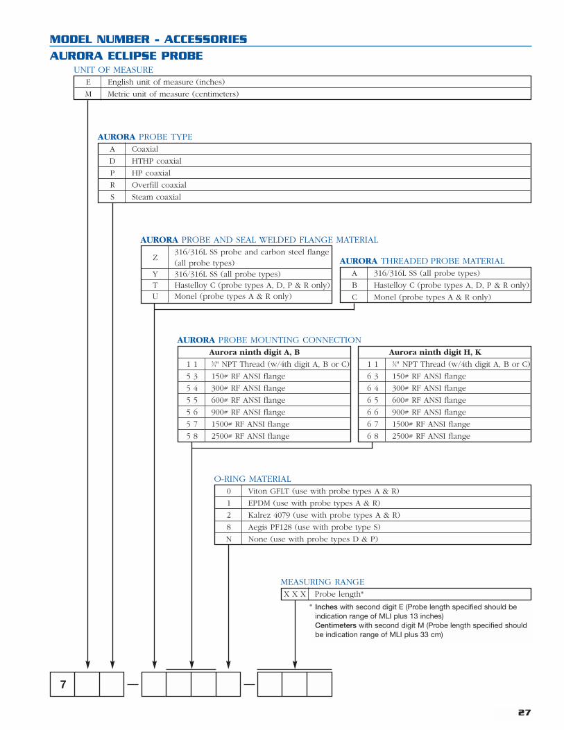
MODEL NUMBER - ACCESSORIES
AURORA ECLIPSE PROBE
E English unit of measure (inches)
M Metric unit of measure (centimeters)
UNIT OF MEASURE
A Coaxial
D HTHP coaxial
P HP coaxial
R Overfill coaxial
S Steam coaxial
AURORA PROBE TYPE
Z316/316L SS probe and carbon steel flange(all probe types)
Y 316/316L SS (all probe types)T Hastelloy C (probe types A, D, P & R only)U Monel (probe types A & R only)
AURORA PROBE AND SEAL WELDED FLANGE MATERIAL
Aurora ninth digit A, B
1 1 3⁄4" NPT Thread (w/4th digit A, B or C)
5 3 150# RF ANSI flange
5 4 300# RF ANSI flange
5 5 600# RF ANSI flange
5 6 900# RF ANSI flange
5 7 1500# RF ANSI flange
5 8 2500# RF ANSI flange
Aurora ninth digit H, K
1 1 3⁄4" NPT Thread (w/4th digit A, B or C)
6 3 150# RF ANSI flange
6 4 300# RF ANSI flange
6 5 600# RF ANSI flange
6 6 900# RF ANSI flange
6 7 1500# RF ANSI flange
6 8 2500# RF ANSI flange
0 Viton GFLT (use with probe types A & R)
1 EPDM (use with probe types A & R)
2 Kalrez 4079 (use with probe types A & R)
8 Aegis PF128 (use with probe type S)
N None (use with probe types D & P)
O-RING MATERIAL
27
7
X X X Probe length*
MEASURING RANGE
* Inches with second digit E (Probe length specified should beindication range of MLI plus 13 inches)Centimeters with second digit M (Probe length specified shouldbe indication range of MLI plus 33 cm)
AURORA PROBE MOUNTING CONNECTION
A 316/316L SS (all probe types)
B Hastelloy C (probe types A, D, P & R only)
C Monel (probe types A & R only)
AURORA THREADED PROBE MATERIAL

MODEL NUMBER - ACCESSORIES
GEMINI ECLIPSE TRANSMITTER
0 4-20 mA
1 4-20 mA with HART
OUTPUT
1 English
2 Spanish
3 French
4 German
MENU LANGUAGE
0 None
A Digital display and keypad
DISPLAY AND KEYPAD
1 Integral, GP, IS & NI, FM/CSA
2 Remote, GP, IS & NI, FM/CSA
3 Integral, EP & NI, FM/CSA
4 Remote, EP & NI, FM/CSA
A Integral, GP & IS, ATEX Exia
B Remote, GP & IS, ATEX Exia
C Integral, EP, ATEX Exd
D Remote, EP, ATEX Exd
E Integral, NI, ATEX Exn
F Remote, NI, ATEX Exn
TRANSMITTER MOUNTING AND APPROVALS
1 Cast aluminum
2 316 stainless steel
HOUSING MATERIAL
0 3⁄4" NPT
1 M20
2 PG 13.5
3 PG 16
CONDUIT ENTRY
7 0 5 5
28
Eclipse withstandard coaxial probe
ProbeInsertionLength
MountingFlange
45°
4.12(105)
Elect.Conn.Qty. 2
3.27(83)
4.00(102)
10.08(256)
2.33(59)
* Probe length specified should be indicationrange of MLI plus 13 inches (33 cm)
*
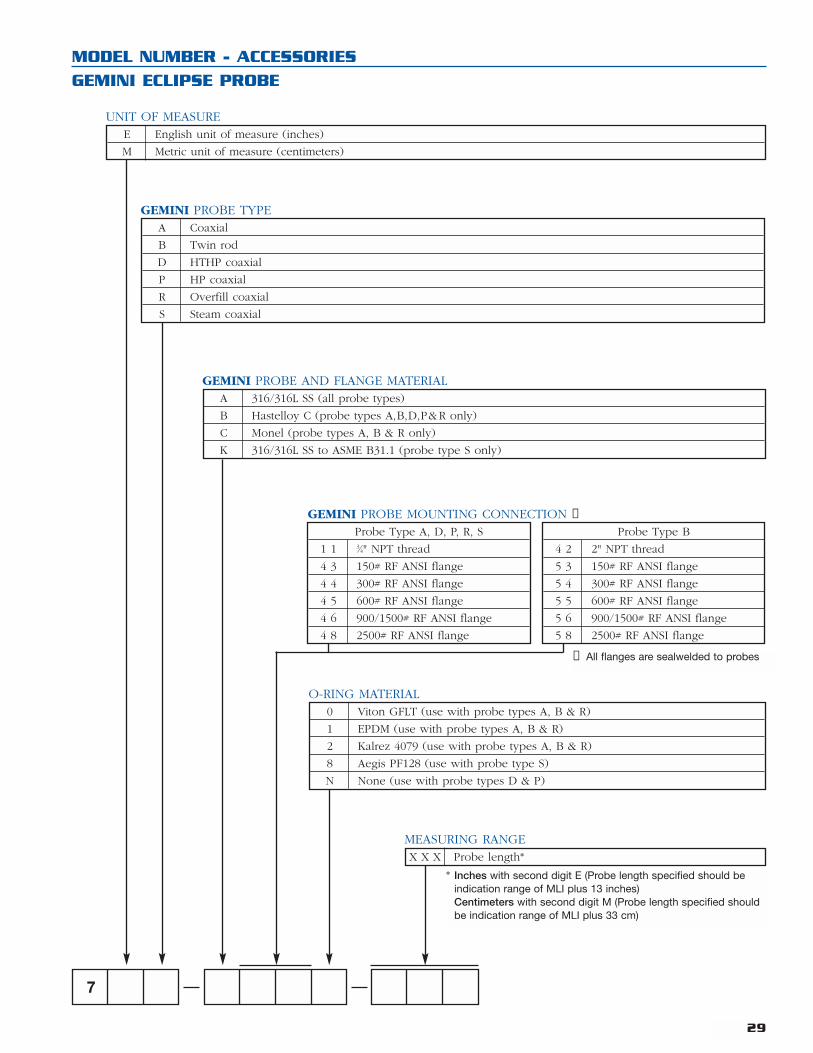
MODEL NUMBER - ACCESSORIES
GEMINI ECLIPSE PROBE
E English unit of measure (inches)
M Metric unit of measure (centimeters)
UNIT OF MEASURE
A Coaxial
B Twin rod
D HTHP coaxial
P HP coaxial
R Overfill coaxial
S Steam coaxial
GEMINI PROBE TYPE
A 316/316L SS (all probe types)
B Hastelloy C (probe types A,B,D,P&R only)
C Monel (probe types A, B & R only)
K 316/316L SS to ASME B31.1 (probe type S only)
GEMINI PROBE AND FLANGE MATERIAL
0 Viton GFLT (use with probe types A, B & R)
1 EPDM (use with probe types A, B & R)
2 Kalrez 4079 (use with probe types A, B & R)
8 Aegis PF128 (use with probe type S)
N None (use with probe types D & P)
O-RING MATERIAL
29
7
X X X Probe length*
MEASURING RANGE
* Inches with second digit E (Probe length specified should beindication range of MLI plus 13 inches)Centimeters with second digit M (Probe length specified shouldbe indication range of MLI plus 33 cm)
Probe Type A, D, P, R, S
1 1 3⁄4" NPT thread
4 3 150# RF ANSI flange
4 4 300# RF ANSI flange
4 5 600# RF ANSI flange
4 6 900/1500# RF ANSI flange
4 8 2500# RF ANSI flange
Probe Type B
4 2 2" NPT thread
5 3 150# RF ANSI flange
5 4 300# RF ANSI flange
5 5 600# RF ANSI flange
5 6 900/1500# RF ANSI flange
5 8 2500# RF ANSI flange
GEMINI PROBE MOUNTING CONNECTION ➀
➀ All flanges are sealwelded to probes
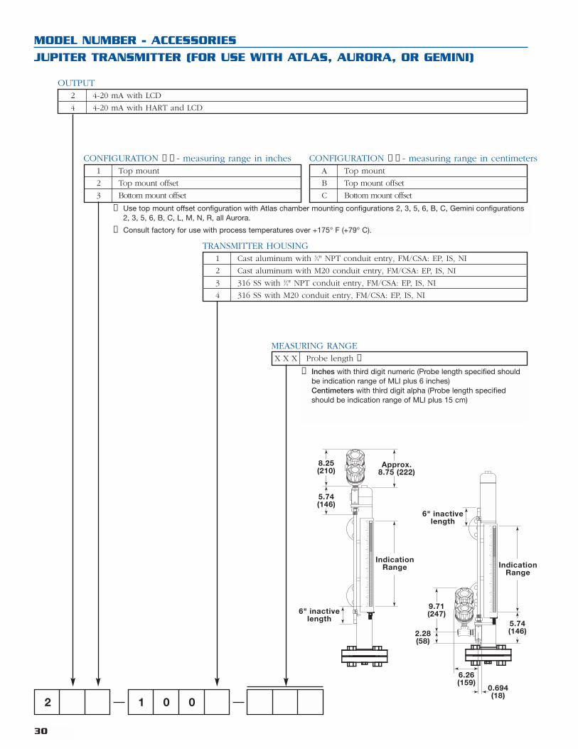
2 4-20 mA with LCD
4 4-20 mA with HART and LCD
OUTPUT
1 Top mount
2 Top mount offset
3 Bottom mount offset
CONFIGURATION ➀➁ - measuring range in inchesA Top mount
B Top mount offset
C Bottom mount offset
CONFIGURATION ➀➁ - measuring range in centimeters
1 Cast aluminum with 3⁄4" NPT conduit entry, FM/CSA: EP, IS, NI
2 Cast aluminum with M20 conduit entry, FM/CSA: EP, IS, NI
3 316 SS with 3⁄4" NPT conduit entry, FM/CSA: EP, IS, NI
4 316 SS with M20 conduit entry, FM/CSA: EP, IS, NI
TRANSMITTER HOUSING
X X X Probe length ➂
MEASURING RANGE
MODEL NUMBER - ACCESSORIES
JUPITER TRANSMITTER (FOR USE WITH ATLAS, AURORA, OR GEMINI)
2 1 0 0
30
➀ Use top mount offset configuration with Atlas chamber mounting configurations 2, 3, 5, 6, B, C, Gemini configurations2, 3, 5, 6, B, C, L, M, N, R, all Aurora.
➁ Consult factory for use with process temperatures over +175° F (+79° C).
➂ Inches with third digit numeric (Probe length specified shouldbe indication range of MLI plus 6 inches)Centimeters with third digit alpha (Probe length specifiedshould be indication range of MLI plus 15 cm)
8.25(210)
5.74(146)
6" inactivelength
IndicationRange
Approx.8.75 (222)
6" inactivelength
6.26(159)
0.694(18)
5.74(146)
IndicationRange
9.71(247)
2.28(58)

MODEL NUMBER - ACCESSORIES
REED CHAIN (FOR USE WITH ATLAS, AURORA, OR GEMINI
1 Aluminum
0 Stainless steel
ENCLOSURE
0 Standard enclosure
2 Standard enclosure with cast aluminum junction box (ORS-3 only)
3 Standard enclosure with stainless steel junction box (ORS-3 only)
ENCLOSURE
0 E 0 0 1
31
MODEL NUMBER
SWITCH (FOR USE WITH ATLAS, AURORA, OR GEMINI)
O E S - 1 Electric 10 amp DPDT snap switch in cast aluminum clamp-mounted housing, NEMA 4X/7/9
O P S - 2 Pneumatic non-bleed 200 psig maximum switch in stainless steel clamp-mounted housing, NEMA 4X
O R S - 3 Electric bi-stable 1 amp SPDT reed switch in stainless steel clamp-mounted housing, NEMA 4X/7/9
SWITCH FOR ATLAS
4.0 (102) Ref.Inactive Length
XXX = SpanActive Length
3.8 (97)REF.
3.5 (90)REF.
4.5 (115)REF.
0.4 (10) REF.Label Bracket
3/4" NPTConduit Conn.
3.0 (76)REF.
3.0 (76)
1/2" MNPT
7.41(188)REF.
7.35(187)
1/4" FNPT
3.0 (76)REF.
5.5 (139)REF.
8.38 (212)REF.
3/4" FNPTconduit connections
OES-100Electro-Magnetic Switch
ORS-300Electro-Magnetic Switch
OPS-200Pneumatic Switch
0 Top mount
1 Bottom mount
MOUNTING CONNECTION
E English unit of measure (inches)
M Metric unit of measure (centimeters)
UNIT OF MEASURE
X X X Indication range ➀
INDICATION RANGE
O C T 4
➀ Actual probe length will be indicationrange plus 8 inches

6646 Complex Drive, Baton Rouge, LA. 70809
Telephone: 225-906-2343
Toll Free: 866-55-Orion (866-556-7466)
Fax: 225-906-2344
E-mail: [email protected]
orioninstruments.com
Copyright © 2003, Orion Instruments, LLP. All rights reserved
Printed in the U.S.A. Bulletin: ORI-138.1 Effective: October 2003