Magnetic Levitation System for the Dissemination of a Non ...
24
Magnetic Levitation System for the Dissemination of a Non-Artifact Based kilogram Zeina Jabbour, Patrick Abbott, Ruimin Liu, Vincent Lee Manufacturing Engineering Laboratory Edwin Williams Electronics and Electrical Engineering Laboratory National Institute of Standards and Technology, Gaithersburg, MD, USA Abstract We describe a new approach to directly link air and vacuum mass measurements. This approach uses magnetic levitation along with vacuum and balance technology to realize vacuum mass measurements. It provides direct traceability to the International Prototype kilogram through the U.S. national prototypes without the intermediary use of vacuum artifacts. This approach will provide a direct link between the national standard of mass currently defined in air and the vacuum-based realizations founded on fundamental constants. We describe the proof-of-concept experiment, basic operation principles and challenges, initial modeling calculations, preliminary results, and the expectations of the next generation system * . Introduction The unit of mass, the kilogram, is the last remaining fundamental SI unit defined by an artifact. There are three main shortcomings to this artifact definition: First, there is a constant danger that the artifact will be damaged or destroyed through mishandling or a catastrophic event at the Bureau International des Poids et Mesures (BIPM) in Sevres, France. Second, since there is only one defining artifact for the entire world, comparisons involving the International Prototype kilogram (IPK) must be done at the BIPM, clearly an inconvenience for distant laboratories. Third and most importantly, the kilogram suffers from long-term instability, which has been attributed to surface effects 1 . Numerous efforts worldwide are aimed at redefining the kilogram with an * Certain commercial equipment, instruments, or materials are identified in this document. Such identification does not imply recommendation or endorsement by the National Institute of Standards and Technology, nor does it imply that the products identified are necessarily the best available for the purpose.
Transcript of Magnetic Levitation System for the Dissemination of a Non ...
Magnetic Levitation System for the Dissemination of a Non-Artifact Based kilogram
Zeina Jabbour, Patrick Abbott, Ruimin Liu, Vincent Lee Manufacturing Engineering Laboratory
Edwin Williams
Electronics and Electrical Engineering Laboratory
National Institute of Standards and Technology, Gaithersburg, MD, USA
Abstract We describe a new approach to directly link air and vacuum mass measurements. This approach uses magnetic levitation along with vacuum and balance technology to realize vacuum mass measurements. It provides direct traceability to the International Prototype kilogram through the U.S. national prototypes without the intermediary use of vacuum artifacts. This approach will provide a direct link between the national standard of mass currently defined in air and the vacuum-based realizations founded on fundamental constants. We describe the proof-of-concept experiment, basic operation principles and challenges, initial modeling calculations, preliminary results, and the expectations of the next generation system*. Introduction
The unit of mass, the kilogram, is the last remaining fundamental SI unit
defined by an artifact. There are three main shortcomings to this artifact
definition: First, there is a constant danger that the artifact will be damaged or
destroyed through mishandling or a catastrophic event at the Bureau
International des Poids et Mesures (BIPM) in Sevres, France. Second, since
there is only one defining artifact for the entire world, comparisons involving the
International Prototype kilogram (IPK) must be done at the BIPM, clearly an
inconvenience for distant laboratories. Third and most importantly, the kilogram
suffers from long-term instability, which has been attributed to surface effects1.
Numerous efforts worldwide are aimed at redefining the kilogram with an
* Certain commercial equipment, instruments, or materials are identified in this document. Such identification does not imply recommendation or endorsement by the National Institute of Standards and Technology, nor does it imply that the products identified are necessarily the best available for the purpose.
invariant of nature.2 These efforts are centered on three main experiments: the
watt balance or electronic realization of the kilogram3, the Avogadro or silicon
approach4, and the atom-based kilogram or ion accumulation5. However, all of
the above approaches suffer from many limitations including the conflicting
needs of performing the experiment in vacuum and the reality of the current
definition of mass in air at atmospheric pressure.
For an alternative definition of the kilogram to rival the current artifact
definition, a relative uncertainty of 2×10⁻⁸ or better6 is required. This level of
precision can only be achieved, in the watt balance for example, if major sources
of uncertainty, such as those associated with index of refraction of air and air
buoyancy correction, are either eliminated or minimized. For this reason, the
watt balance is currently running under vacuum conditions, which is incompatible
with the current realization of the mass unit (and all associated methods of
dissemination of the unit) in air at ambient atmospheric pressure. Transfer of the
unit to vacuum requires an unbroken traceability chain to the International
Prototype kilogram, as well as characterization of the stability of the artifacts and
their surfaces during transfers from air to vacuum and vice versa. This
requirement remains a major challenge for further advances in redefining the unit
of mass. Therefore, there is a critical need for redefining how artifact mass
metrology is maintained and disseminated; furthermore, it requires the ability to
measure artifacts in vacuum, and directly tie the vacuum measurements to both
the IPK and the alternative definition with a measurement uncertainty as good as
or better than the uncertainty of the alternative definition of the kilogram.

Many of the world’s metrology labs make an indirect link between air and vacuum
mass measurements by measuring mass in vacuum and then characterizing the
absorption layers of contaminants7during vacuum to air exchanges and vice-
versa. We describe a system based on a specially designed high precision mass
balance for the simultaneous comparison of a mass in air to a mass in vacuum.
This system relies on a magnetic levitation technique (described below) to couple
a mass pan in air, through a non-magnetic interface, to a separate vacuum
chamber containing the second mass pan and the high precision mass balance.
This system will enable the direct linkage of the NIST watt realization in vacuum
to the current SI definition of the kilogram in air.
Motivation and Proof of Concept Apparatus
Around 1950, the experiments of Clark8 and Beams9 suggested that magnetic
suspension could be used as a sensitive analytical balance under conditions
where standard balances are difficult to use, such as for weighing materials
inside vacuum chambers, in liquid, vapors, or gases. Since that time, many
useful instruments involving magnetic levitation have been developed, including
commercial balances,10 densitometers,11 and the spinning rotor gauge for
measuring gas pressure12. For a mass balance application, the method of
magnetic levitation used is very critical to the overall performance of the balance,
as well as to the construction of the system. If the position of the levitated mass
is not stable about a point of equilibrium, the precision of the mass comparison
will be limited by the fluctuation of the balance’s reading. In addition, the
presence of any stray magnetic field gradients due to the presence of
ferromagnetic materials near the balance will influence its reading13. Therefore,
the magnetic field configuration used for levitating the mass in air must be
properly shielded from the balance, and all materials used in the construction of
the system must be non-magnetic.
As a result of Earnshaw’s theorem,14 stable levitation of a ferromagnetic object
cannot be achieved through the exclusive use of permanent magnets. Instead, it
is necessary to regulate the magnetic field using an active feedback control
system, e.g., a solenoid whose magnetic field can be varied. The role of the
variable magnet (solenoid) is to quickly adjust the overall magnetic field in
response to a change in the levitated object’s position. Positional feedback can
be provided in many ways using a variety of different sensor technologies. Servo
control of the magnetic field is used to realize stable levitation using the
positional feedback signal as an input.
For the proof-of-concept apparatus, the magnetic levitation system must
generate enough force to levitate a 1 kg mass standard and its pan suspension
assembly. There are competing interests to be addressed when choosing a
levitation scheme. First, the gap distance between the magnet poles needs to be
large enough to accommodate the thickness of the interface between the
vacuum and air chambers. Second, the change in force per unit vertical distance

between the poles should be as small as possible in order to improve stability
and reduce the resolution requirements on the positioning feedback system.
Finally, the configuration must produce stable levitation that is not easily made
unstable by a torque or force in any direction. Therefore, a restoring force is
needed for any deviation in position that is perpendicular to the levitating
magnetic field.
In order to evaluate the magnetic fields produced by a given levitation design, we
used commercially available finite element analysis-based (FEA) simulation
software to solve Maxwell’s equations. The software is very versatile, allowing
the use of both static and dynamic fields as well as magnetic and non-magnetic
materials. Construction materials are chosen from a built-in library and
configured into an array that can be solved both two and three dimensionally.
From the FEA solution of the array, one can create flux plots and determine the
forces acting on the levitated body. The force on a magnetized object placed in a
magnetic field may be calculated from the following vector equation:
)HM(Frrrr
⋅∇= (1)
Here, F is the force, M is the magnetic moment of the object, and H is the
magnetic field. Equation 1 states that the force goes as the gradient of the
magnetic field; in other words, a non-uniform magnetic field is necessary for a
force to be exerted on the object. Fortunately, the same FEA-based software
used to simulate the magnetic field of the levitation models can also calculate the
force on the object to be levitated. The following sections describe the simulation
of three different levitation designs under consideration for use in the proof of
concept apparatus.
Attractive Magnetic Levitation Model
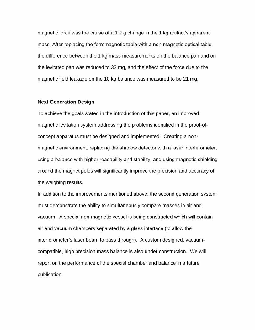
Figure 1A shows an attractive magnetic levitation system. The force for levitation
is produced by two permanent magnets whose magnetic moments are oriented
in a parallel direction so that the magnetic pole faces attract each other, as
depicted in the block diagram of Figure 1B. The upper magnetic pole is fixed
while the magnetic pole in the lower chamber (attached to the mass to be
levitated—not shown) is free to move vertically. Permanent magnets are colored
orange and the pole faces are colored blue. The upper magnet has a solenoid
attached to it for active control of the levitating force as discussed above. Figure
1C shows that the distribution of flux lines between the poles is very dense,
indicating a strong attractive force.
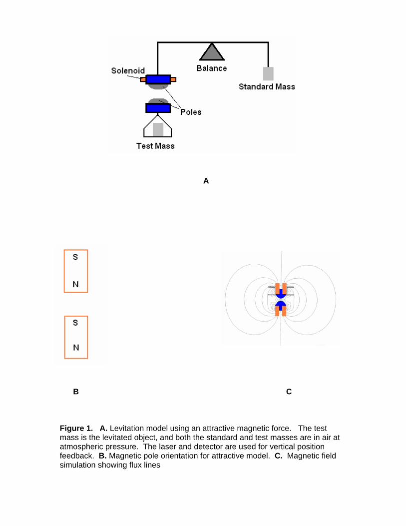
Figure 2A presents a graph of the force on the object to be levitated as a function
of its distance from the upper magnet (referred to as “the gap”) using the
attractive configuration. Permanent magnets are specified by their ability to
resist demagnetization, called the coercivity, which is expressed in units of A/m.
In the attractive model, the force on the levitated object will depend on the
coercivity of the permanent magnet materials used, and the three plots in Figure
2A correspond to different coercivity permanent magnet materials. Referring to

Figure 2A and Table 1, a 2.4 kg mass pan can be levitated at a gap distance of
19.7 mm if the strongest coercivity magnetic material is used in the construction
of the levitation system. Placing a 1 kg mass on the pan to raise the total
levitated mass to 3.4 kg changes the gap distance to 14.6 mm. While this gap
will allow a thick glass vacuum window to be used, the positional sensitivity is
also the largest for any of the three types of magnets, -0.43 mg/nm. The other
two types of magnets yield a smaller positional sensitivity, but the gap size is also
reduced, especially for the weakest of the three magnet materials (-813 242
A/m).
Figure 2B shows the sensitivity of the vertical and horizontal forces to a small
change in horizontal position for two different initial vertical positions. Note that
while the vertical force Fz remains nearly the same, the horizontal force changes
in a nearly linear fashion. Furthermore, the horizontal force is negative, meaning
that it is in opposition to the direction of movement, similar to the restoring force
of a stretched spring. This is a very desirable characteristic of the attractive
model, as it eliminates the need for active horizontal control.
Attractive/Repulsive Magnetic Levitation Model
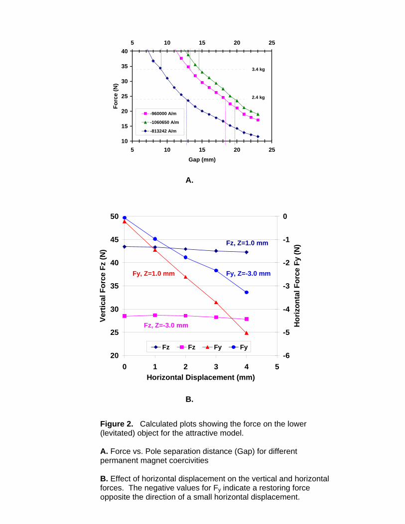
Figure 3A shows a different type of model, one that uses both attractive and
repulsive magnetic forces. In this model the end of the connecting rod to the air
chamber mass pan has a ring-shaped permanent magnet with the polarity as
shown. This ring magnet is situated in the magnetic field produced by two other

ring magnets, one above and one below the connecting rod ring magnet. From
the relative polarities of the three magnets involved, it is easily seen that the
lower ring magnet repels the connecting rod magnet while the upper ring magnet
attracts it. The orientation of magnets and a simulation of the magnetic field for
this configuration are shown in Figures 3B and 3C respectively; a Force vs.
Vertical Position plot is shown in Figure 4A. Figure 4B shows that the horizontal
force increases for a small horizontal deviation in position; this means that a
change in horizontal position will induce a force that will tend to knock the
levitated object out of equilibrium. Table 2 summarizes the information
presented in Figure 4.
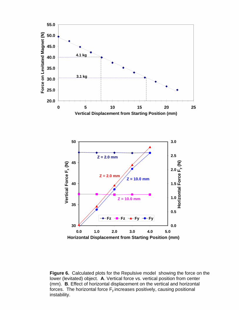
Repulsive Magnetic Force Levitation Model
Figure 5A shows a model that uses a purely repulsive magnetic force to achieve
levitation. It is evident from the magnet polarities shown that the lower ring
magnet must balance the weight of the connecting rod, suspension pan, and
mass under test through a purely repulsive magnetic force. A variable field
solenoid is attached to the fixed magnet in order to maintain stable levitation.
Plots of vertical and horizontal force as a function of position are presented in
Figures 6A and 6B. Figure 6B shows that the horizontal force increases for a
small horizontal deviation in position, leading to instability. Generally speaking,
stable magnetic levitation using a repulsive force configuration is difficult to
achieve. Active control of the horizontal and rotational degrees of freedom is
needed, which makes the system much more difficult to implement. However,
the purely repulsive configuration has the advantage of being less sensitive
regarding force as a function of vertical position than the attractive force model,
which relaxes the requirements on the vertical positional feedback system.
Proof-of-Concept Apparatus Design and Performance
The characteristics of each of the three levitation models are summarized in
Table 3. Based on the inherent horizontal stability and the relative simplicity of
construction, we decided to build a proof-of-concept levitation system using an
attractive magnetic force model. Although simulations indicated that the
sensitivity of the vertical force vs. gap distance may be a factor of 10 larger than
for the models using a repulsive force, we used this design because of its relative
simplicity and the presence of a horizontal restoring force.
A schematic drawing of an attractive magnetic levitation design is shown in
Figure 7. For simplicity, the proof-of-concept apparatus was constructed with
both masses in air at atmospheric pressure. In Figure 7, the vertical position
signal is provided by a “shadow sensor” photodiode that detects a laser beam
that just skims the top of the magnetic pole that is attached to the levitated
assembly. The solenoid field is servo controlled about a position corresponding
to a certain output level of the photodiode detector. Any change in the detected
light level will cause the solenoid field to be appropriately increased or decreased
to maintain stable levitation. Servo control is implemented with a simple PID
(Proportional, Integral, and Derivative position loop) controller computer board.
The mass of the levitation parts including the pan suspension is 0.60 kg. Figure
8 is a plot of Magnetic Force vs. Pole Separation calculated from the FEA
simulation software using the construction parameters of the system. This plot
shows that the stable separation position between the fixed and levitated parts
(mass pan without 1 kg mass) is 22 mm. When a 1 kg mass is placed on the pan,
the total mass of the levitation parts is 1.60 kg and it can be balanced at a
separation distance of 8.5 mm. Note that at this position, the attracting force
gradient is 0.14 mg/nm.
A 10-kg balance was used in the Proof-of-Concept apparatus. The
manufacturer’s specified readability and repeatability of this balance are both 1
mg, but the precision of actual measurements will depend on environmental and
experimental conditions. When measuring a 1 kg mass under magnetic
suspension, the measured standard deviation was 11 mg, a factor of 10 higher
than the balance’s specification. Much of this noise may come from inadequate
temperature control, turbulent airflow from the laboratory, and instability of the
position of levitation. The accuracy of mass measurements is also influenced by
experimental conditions. For instance, a parasitic magnetic force was found
between the levitation device and the test table; this was not unexpected, as the
table has significant permanent magnetism. This extra force adds to the force
provided by the magnetic poles, so that when the test mass was placed on and
off the levitated mass pan, the distance between the table and the levitated parts
changed by 12 mm instead of the expected 13.5 mm (see Figure 8). This effect
causes the balance reading to be inaccurate, and we found that the extra
magnetic force was the cause of a 1.2 g change in the 1 kg artifact’s apparent
mass. After replacing the ferromagnetic table with a non-magnetic optical table,
the difference between the 1 kg mass measurements on the balance pan and on
the levitated pan was reduced to 33 mg, and the effect of the force due to the
magnetic field leakage on the 10 kg balance was measured to be 21 mg.
Next Generation Design
To achieve the goals stated in the introduction of this paper, an improved
magnetic levitation system addressing the problems identified in the proof-of-
concept apparatus must be designed and implemented. Creating a non-
magnetic environment, replacing the shadow detector with a laser interferometer,
using a balance with higher readability and stability, and using magnetic shielding
around the magnet poles will significantly improve the precision and accuracy of
the weighing results.
In addition to the improvements mentioned above, the second generation system
must demonstrate the ability to simultaneously compare masses in air and
vacuum. A special non-magnetic vessel is being constructed which will contain
air and vacuum chambers separated by a glass interface (to allow the
interferometer’s laser beam to pass through). A custom designed, vacuum-
compatible, high precision mass balance is also under construction. We will
report on the performance of the special chamber and balance in a future
publication.

A B C Figure 1. A. Levitation model using an attractive magnetic force. The test mass is the levitated object, and both the standard and test masses are in air at atmospheric pressure. The laser and detector are used for vertical position feedback. B. Magnetic pole orientation for attractive model. C. Magnetic field simulation showing flux lines
10
15
20
25
30
35
40
5 10 15 20 25Gap (mm)
Forc
e (N
)
5 10 15 20 25
-960000 A/m
-1060650 A/m
-813242 A/m
2.4 kg mass
3.4 kg
A.
20
25
30
35
40
45
50
0 1 2 3 4 5Horizontal Displacement (mm)
Vert
ical
For
ce F
z (N
)
-6
-5
-4
-3
-2
-1
0
Hor
izon
tal F
orce
Fy
(N)
Fz Fz Fy Fy
Fy, Z=1.0 mm Fy, Z=-3.0 mm
Fz, Z=1.0 mm
Fz, Z=-3.0 mm
B.
Figure 2. Calculated plots showing the force on the lower (levitated) object for the attractive model. A. Force vs. Pole separation distance (Gap) for different permanent magnet coercivities B. Effect of horizontal displacement on the vertical and horizontal forces. The negative values for Fy indicate a restoring force opposite the direction of a small horizontal displacement.

Magnet
material 1
Magnet
material 2
Magnet
material 3
Coercivity -813 242 A/m -960 000 A/m -1 060 650/A/m
2.4 kg 12.8 mm 18.3 mm 19.7 mm
3.4 kg 9.2 mm 13.3 mm 14.6 mm
Difference -3.6 mm -5.0 mm -5.1 mm
Sensitivity -0.27 mg/nm -0.39 mg/nm -0.43 mg/nm
Table 1. Levitation distances and position sensitivities for two levitated objects whose difference is 1 kg. The force vs. position plots in Figure 2 were used
A.
B. C.
Figure 3. A. Levitation model using a combination of attractive and repulsive magnetic forces. The test mass is attached to the levitated object. B. Magnetic pole orientation for combination model. C. Magnetic field simulation showing flux lines
B

30
35
40
45
50
-20 -15 -10 -5 0 5 10 15 20
Vertical Position from Center (mm)
Forc
e on
Lev
itate
d O
bjec
t (N
)
30
35
40
45
50
55 55
4.8 kg
3.8 kg
A
30.0
32.0
34.0
36.0
38.0
40.0
42.0
44.0
46.0
0 0.5 1 1.5 2 2.5 3 3.5Horizontal Displacement (mm)
Fz (N
)
-0.50
0.00
0.50
1.00
1.50
2.00
2.50
3.00
3.50
Fx (N
)
Fz Fz Fx Fx
Z = 16.6 mm
Z = 2.6 mm
Z = 2.6 mm
Z = 16.6 mm
B Figure 4. Calculated plots for the Combination Attractive/Repulsive model
showing the force on the lower (levitated) object. A. Vertical force vs. vertical position from center (mm). B. Effect of horizontal displacement on the vertical and horizontal forces. The horizontal force increases positively, causing positional instability.

Magnet material coercivity -960 000 A/m
3.8 kg 16.5 mm
4.8 kg 3.0 mm
Difference 13.5 mm
Sensitivity -0.09 mg/nm
Table 2. Levitation distance and position sensitivity for two levitated objects whose difference is 1 kg. The Force vs. Position plot in Figure 4A was used

A B
Figure 5 A. Levitation model based on repulsive magnetic force. B. Magnetic field simulation showing flux lines. The green material is magnetic shielding, which “short circuits” flux lines.
20.0
25.0
30.0
35.0
40.0
45.0
50.0
55.0
0 5 10 15 20 25Vertical Displacement from Starting Position (mm)
Forc
e on
Lev
itate
d M
agne
t (N
)
4.1 kg
3.1 kg
30
35
40
45
50
0.0 1.0 2.0 3.0 4.0 5.0Horizontal Displacement from Starting Position (mm)
Ver
tical
For
ce F
z (N
)
0.0
0.5
1.0
1.5
2.0
2.5
3.0
Hor
izon
tal F
orce
Fy (
N)
Fz Fz Fy Fy
Z = 10.0 mm
Z = 2.0 mm
Z = 2.0 mm
Z = 10.0 mm
Figure 6. Calculated plots for the Repulsive model showing the force on the lower (levitated) object. A. Vertical force vs. vertical position from center (mm). B. Effect of horizontal displacement on the vertical and horizontal forces. The horizontal force Fy increases positively, causing positional instability.
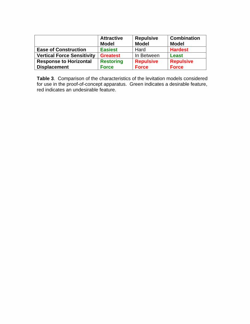
Attractive
Model Repulsive Model
Combination Model
Ease of Construction Easiest Hard Hardest Vertical Force Sensitivity Greatest In Between Least Response to Horizontal Displacement
Restoring Force
Repulsive Force
Repulsive Force
Table 3. Comparison of the characteristics of the levitation models considered for use in the proof-of-concept apparatus. Green indicates a desirable feature, red indicates an undesirable feature.
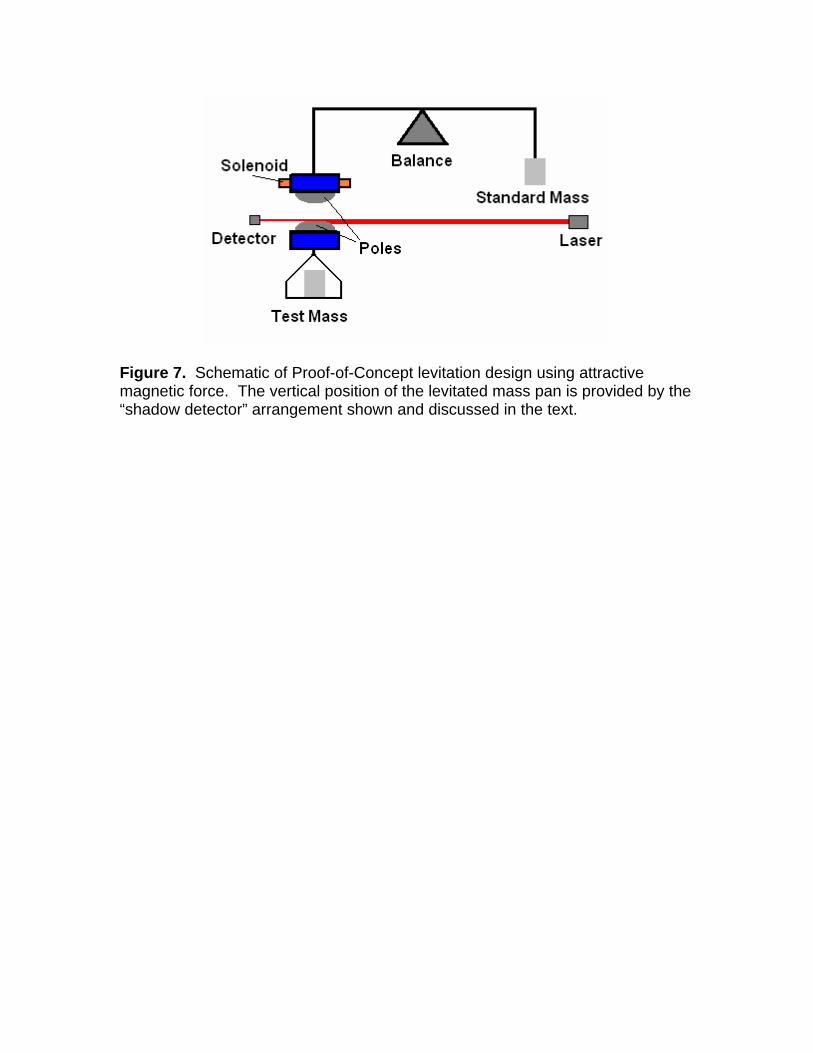
Figure 7. Schematic of Proof-of-Concept levitation design using attractive magnetic force. The vertical position of the levitated mass pan is provided by the “shadow detector” arrangement shown and discussed in the text.

0
5
10
15
20
25
4 6 8 10 12 14 16 18 20 22 24 26
Gap Distance (mm)
Figure 8. Magnetic Force generated by the attractive model used in the proof of concept apparatus. The black line is a least-squares fit to the data. The empty mass pan will levitate at around 22 mm (intersection of pink and green lines with graph) and the 1 kg mass on the pan will levitate at 8mm (intersection of blue and green lines with graph).
Forc
e on
vi
td
Pt
)s
(Nar
0.6 kg (pan empty)
1.6 kg (1 kg mass on pan)
ate
Le
References
1 Davidson, S., Metrologia 40, 324-338 (2003). 2 Metrologia 40, 6, (2003) Special Issue on Mass 3 Eichenberger, A., Jeckelmann, B., and Richard, P., Metrologia 40, 356–365 (2003) 4 Becker, P., Metrologia 40, 366–375 (2003). 5 Gläser, M., Metrologia 40, 376–386 (2003). 6 CIPM Recommendation (2007). 7Seah, M.P. et. al., Metrologia 31, 93-108 (1994). 8 John W. Clark, The Review of Scientific Instruments, 18, 12, (1947). 9 J.W. Beams, Phys. Rev. 78, 471 - 472 (1950). 10 For example, the Mag-Lev Balance by Abbess Instruments and Systems, Inc., Ashland, MA USA website: http://www.abbess.com/physcis/maglev.html 11 Dale V. Ulrich, D.W. Kupke, and J.W. Beams, Proceedings of the National Academy of Science, 52, 349-355 (1964). 12 J.K. Fremerey, J. Vac. Sci. Technol. A3, 1715 (1985). 13 R. Davis and M. Gläser, Metrologia 40, 339-355 (2003). 14 S. Earnshaw, Trans. Cambridge Phil. Soc., 7, 97-112 (1839).