24.1. 24.2 24.3 Magnetic PolesMagnetic Field 24.4 Magnetic Field Torque.
Superconducting Magnet Division
Ramesh Gupta, BNLKEK-BNL on Combined Function Magnets, June 12, 2003 Slide No. 1
Magnetic Field Control
Ramesh GuptaSuperconducting Magnet Division Brookhaven National Laboratory
Superconducting Magnet Division
Ramesh Gupta, BNLKEK-BNL on Combined Function Magnets, June 12, 2003 Slide No. 2
Similarities Between RHIC and KEK Magnets
• The iron is very close to the coil in both RHIC dipole and quadrupole magnets and in KEK combined function magnets.
• Earlier one would have expected a large value of saturation-induced harmonics in such cases. However, we have employed a number of techniques to make saturation-induced harmonics very small.
• We would share our experience with you.
Superconducting Magnet Division
Ramesh Gupta, BNLKEK-BNL on Combined Function Magnets, June 12, 2003 Slide No. 3
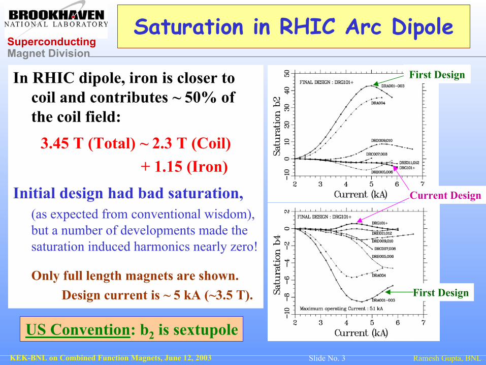
Saturation in RHIC Arc Dipole
In RHIC dipole, iron is closer to coil and contributes ~ 50% of the coil field:
3.45 T (Total) ~ 2.3 T (Coil) + 1.15 (Iron)
Initial design had bad saturation,(as expected from conventional wisdom), but a number of developments made the saturation induced harmonics nearly zero!
Only full length magnets are shown.Design current is ~ 5 kA (~3.5 T).
Current Design
First Design
First Design
US Convention: b2 is sextupole
Superconducting Magnet Division
Ramesh Gupta, BNLKEK-BNL on Combined Function Magnets, June 12, 2003 Slide No. 4
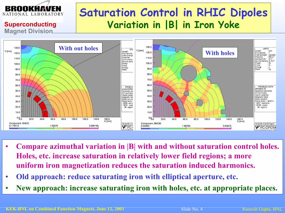
Saturation Control in RHIC DipolesVariation in |B| in Iron Yoke
• Compare azimuthal variation in |B| with and without saturation control holes. Holes, etc. increase saturation in relatively lower field regions; a more uniform iron magnetization reduces the saturation induced harmonics.
• Old approach: reduce saturating iron with elliptical aperture, etc.• New approach: increase saturating iron with holes, etc. at appropriate places.
With out holesWith holes

Superconducting Magnet Division
Ramesh Gupta, BNLKEK-BNL on Combined Function Magnets, June 12, 2003 Slide No. 5
Saturation Control in RHIC DipolesVariation in (µ-1)/(µ+1) in Iron Yoke
• It is better to examine (µ-1)/(µ+1) instead of |B|. As it appears in various formula, e.g.
It also provides a better scale to compare the magnetization (see pictures).• Compare the azimuthal variation in (µ-1)/(µ+1) with and without saturation control
holes, particularly near the yoke inner surface. A more uniform iron magnetization reduces the saturation induced harmonics.
With out holesWith holes
Superconducting Magnet Division
Ramesh Gupta, BNLKEK-BNL on Combined Function Magnets, June 12, 2003 Slide No. 6
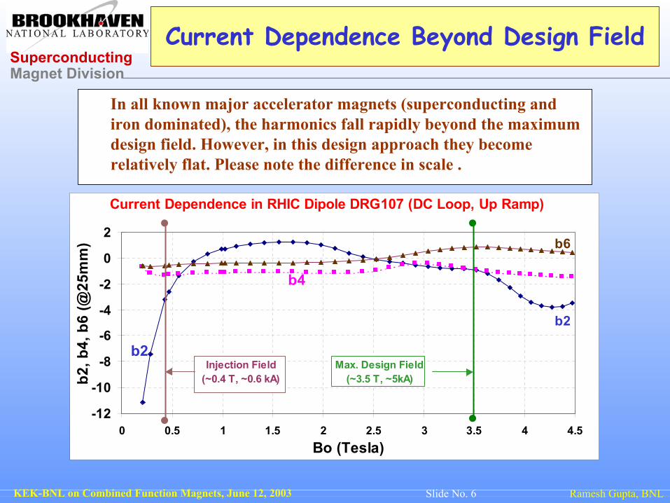
Current Dependence Beyond Design Field
In all known major accelerator magnets (superconducting and iron dominated), the harmonics fall rapidly beyond the maximum design field. However, in this design approach they become relatively flat. Please note the difference in scale .
-12
-10
-8
-6
-4
-2
0
2
0 0.5 1 1.5 2 2.5 3 3.5 4 4.5Bo (Tesla)
b2, b
4, b
6 (@
25m
m)
b2
b4
b6
b2
Current Dependence in RHIC Dipole DRG107 (DC Loop, Up Ramp)
Max. Design Field(~3.5 T, ~5kA)
Injection Field(~0.4 T, ~0.6 kA)
Superconducting Magnet Division
Ramesh Gupta, BNLKEK-BNL on Combined Function Magnets, June 12, 2003 Slide No. 7
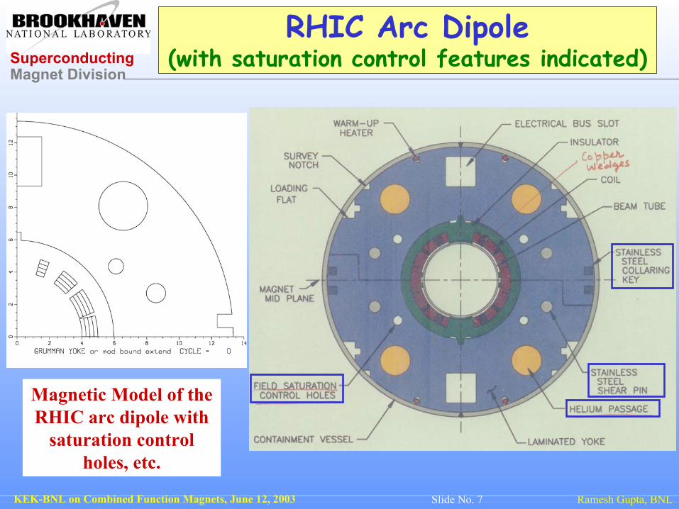
RHIC Arc Dipole(with saturation control features indicated)
Magnetic Model of the RHIC arc dipole with
saturation control holes, etc.

Superconducting Magnet Division
Ramesh Gupta, BNLKEK-BNL on Combined Function Magnets, June 12, 2003 Slide No. 8
Influence of Saturation Control Hole
A RHIC 80 mm dipole was rebuilt after punching saturation control holes in the lamination.
A significant reduction in the saturation-induced (current dependence of) field harmonics can be seen.
This feature was adopted in the RHIC production magnets.
Superconducting Magnet Division
Ramesh Gupta, BNLKEK-BNL on Combined Function Magnets, June 12, 2003 Slide No. 9
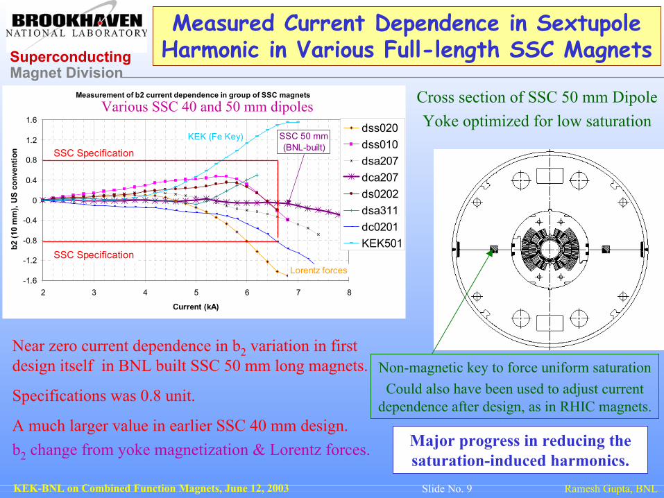
Measured Current Dependence in SextupoleHarmonic in Various Full-length SSC Magnets
Near zero current dependence in b2 variation in first design itself in BNL built SSC 50 mm long magnets.
Specifications was 0.8 unit.
A much larger value in earlier SSC 40 mm design.b2 change from yoke magnetization & Lorentz forces. Major progress in reducing the
saturation-induced harmonics.
Cross section of SSC 50 mm DipoleYoke optimized for low saturation
Measurement of b2 current dependence in group of SSC magnets
-1.6
-1.2
-0.8
-0.4
0
0.4
0.8
1.2
1.6
2 3 4 5 6 7 8
Current (kA)
b2 (1
0 m
m),
US
conv
entio
n
dss020dss010dsa207dca207ds0202dsa311dc0201KEK501
SSC 50 mm (BNL-built)SSC Specification
SSC Specification
KEK (Fe Key)
Lorentz forces
Various SSC 40 and 50 mm dipoles
Non-magnetic key to force uniform saturationCould also have been used to adjust current
dependence after design, as in RHIC magnets.
Superconducting Magnet Division
Ramesh Gupta, BNLKEK-BNL on Combined Function Magnets, June 12, 2003 Slide No. 10
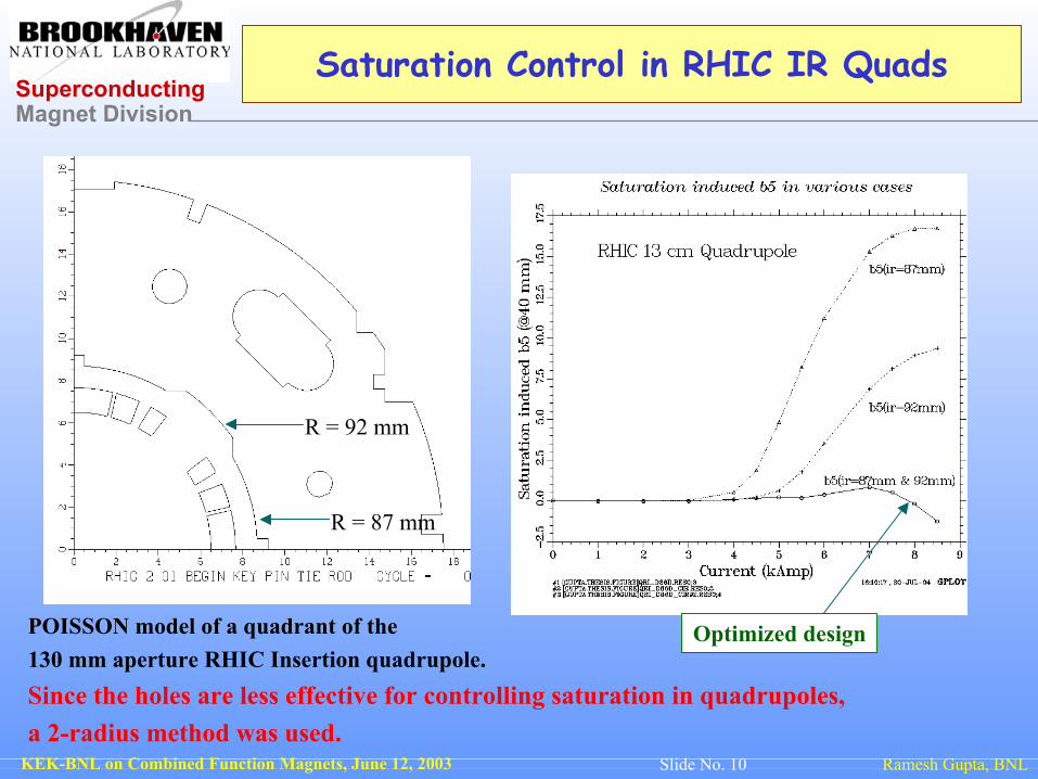
Saturation Control in RHIC IR Quads
POISSON model of a quadrant of the 130 mm aperture RHIC Insertion quadrupole.Since the holes are less effective for controlling saturation in quadrupoles, a 2-radius method was used.
R = 92 mm
R = 87 mm
Optimized design

Superconducting Magnet Division
Ramesh Gupta, BNLKEK-BNL on Combined Function Magnets, June 12, 2003 Slide No. 11
Octupole in Quadrupoles When Quad Assembled Like Dipoles

Superconducting Magnet Division
Ramesh Gupta, BNLKEK-BNL on Combined Function Magnets, June 12, 2003 Slide No. 12
A Simple Method For Removing Octupole From Quad

Superconducting Magnet Division
Ramesh Gupta, BNLKEK-BNL on Combined Function Magnets, June 12, 2003 Slide No. 13
Saturation Control in SSC 2-in-1 Dipole
The case when the current in the same in the two apertures
The case when the ratio of the current in the two aperture is 2:1
The hole in between the two apertures minimizes the normal
quadrupole harmonics at high fields.
Superconducting Magnet Division
Ramesh Gupta, BNLKEK-BNL on Combined Function Magnets, June 12, 2003 Slide No. 14
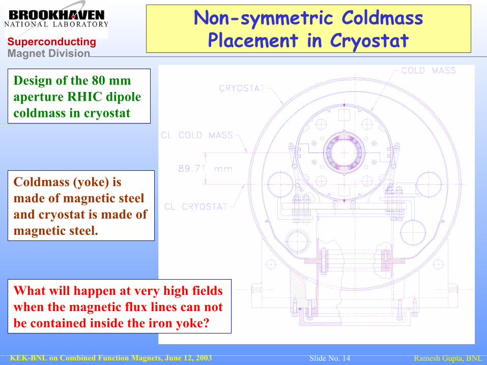
Non-symmetric Coldmass Placement in Cryostat
Design of the 80 mm aperture RHIC dipole coldmass in cryostat
Coldmass (yoke) is made of magnetic steel and cryostat is made of magnetic steel.
What will happen at very high fields when the magnetic flux lines can not be contained inside the iron yoke?
Superconducting Magnet Division
Ramesh Gupta, BNLKEK-BNL on Combined Function Magnets, June 12, 2003 Slide No. 15
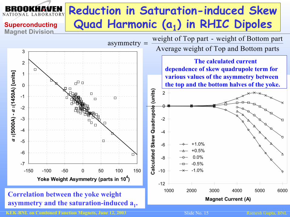
Reduction in Saturation-induced Skew Quad Harmonic (a1) in RHIC Dipoles
-7
-6
-5
-4
-3
-2
-1
0
1
2
3
-150 -100 -50 0 50 100 150
Yoke Weight Asymmetry (parts in 104)
a1(
5000
A) -
a1(
1450
A) [
units
]
Correlation between the yoke weight asymmetry and the saturation-induced a1.
-12
-10
-8
-6
-4
-2
0
2
4
1000 2000 3000 4000 5000 6000
Magnet Current (A)
Cal
cula
ted
Skew
Qua
drup
ole
(uni
ts)
+1.0% +0.5% 0.0% -0.5% -1.0%
The calculated current dependence of skew quadrupole term for various values of the asymmetry between the top and the bottom halves of the yoke.
asymmetry weight of Top part - weight of Bottom partAverage weight of Top and Bottom parts
=

Superconducting Magnet Division
Ramesh Gupta, BNLKEK-BNL on Combined Function Magnets, June 12, 2003 Slide No. 16
A Flexible Design from the Beginning
Design Philosophy:• Start out a design from the beginning itself, that allows significant adjustability for field harmonics and mechanical parameters (cable thickness, wedges, etc.).
• A flexible design is generally economical, efficient and produces magnets with better performance. I think it’s a prudent approach.
Geometric: Start with a larger than required shim and midplane cap. Then adjust it, as required without changing the cross-section of the cured coil. One can also adjust the layers of wedge/cable insulation, if needed. These three parameters can adjust, first two allowed harmonics and pre-stress or cable insulation. This approach was used extensively in various RHIC magnets.
Saturation: Start out with holes and fill them with iron rods. Or, punch holes in laminations later.
midplane
pole
Insulation
In KEK, C.F. dipole, one may consider adjusting for quad and sextupole component.
Superconducting Magnet Division
Ramesh Gupta, BNLKEK-BNL on Combined Function Magnets, June 12, 2003 Slide No. 17
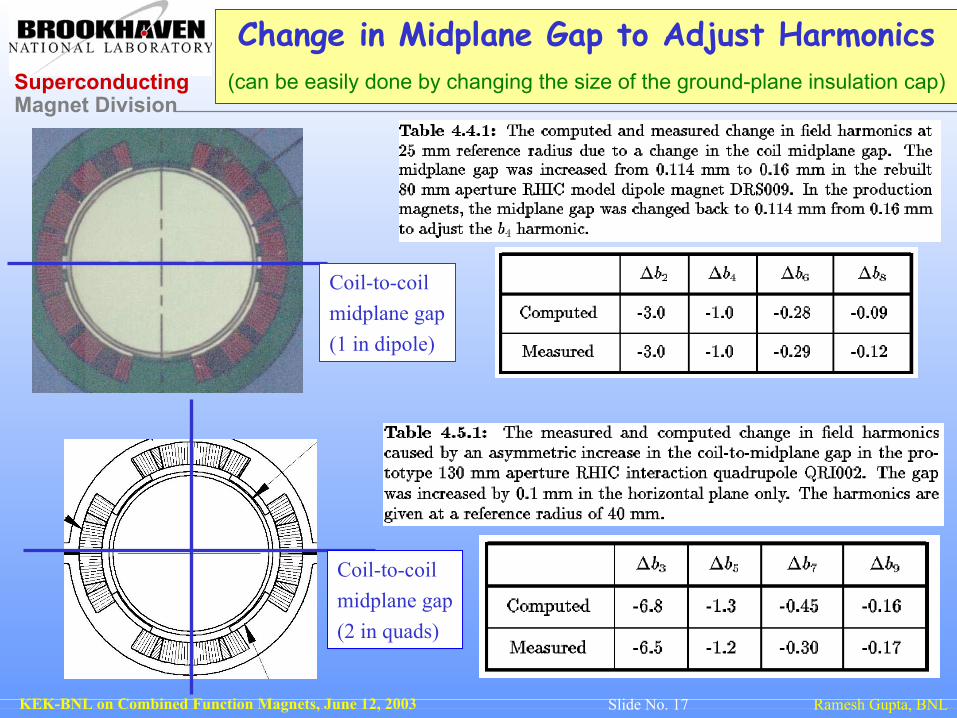
Change in Midplane Gap to Adjust Harmonics(can be easily done by changing the size of the ground-plane insulation cap)
Coil-to-coil midplane gap(1 in dipole)
Coil-to-coil midplane gap(2 in quads)

Superconducting Magnet Division
Ramesh Gupta, BNLKEK-BNL on Combined Function Magnets, June 12, 2003 Slide No. 18
RHIC 100 mm Aperture Insertion Dipole:The first magnet gets the body harmonics right
-5.E-04-4.E-04-3.E-04-2.E-04-1.E-040.E+001.E-042.E-043.E-044.E-045.E-04
-80 -60 -40 -20 0 20 40 60 80Percentage of Coil Radius
dBy/
Bo
Field Error Profile on the midplane at an Intermediate Field
Geometric Field Errors on the X-axis of DRZ101 Body
First magnet and first attempt in RHIC 100 mm aperture insertion dipole A number of things were done in the test assembly to get pre-stress & harmonics right
Harmonics at 2 kA (mostly geometric).Measured in 0.23 m long straigth section.
Reference radius = 31 mmb1 -0.39 a2 -1.06b2 -0.39 a3 -0.19b3 -0.07 a4 0.21b4 0.78 a5 0.05b5 -0.05 a6 -0.20b6 0.13 a7 0.02b7 -0.03 a8 -0.16b8 0.14 a9 -0.01b9 0.02 a10 0.01b10 -0.04 a11 -0.06b11 0.03 a12 -0.01b12 0.16 a13 0.06b13 -0.03 a14 0.03b14 -0.10 a15 0.02
All harmonics are within or close to one sigma of RHIC arc dipoles.
Note: Field errors are within 10-4 at 60% of coil radius and ~4*10-4 at 80% radius.Later magnets had adjustments for integral field and saturation control. The coil cross-section never changed.

Superconducting Magnet Division
Ramesh Gupta, BNLKEK-BNL on Combined Function Magnets, June 12, 2003 Slide No. 19
BASIC KEK Model on POISSON for Carrying Out Design Studies
It’s easier to put/vary the holes, etc. in POISSON, as mesh does not require topology to be fixed.

Superconducting Magnet Division
Ramesh Gupta, BNLKEK-BNL on Combined Function Magnets, June 12, 2003 Slide No. 20
Computed Fields by POISSON
The vertical Field Component at 1 kA
The Field Gradient
Results of preliminary work.
We are having a productive discussion for evaluating different ideas.

Superconducting Magnet Division
Ramesh Gupta, BNLKEK-BNL on Combined Function Magnets, June 12, 2003 Slide No. 21
Some Possibilities in Fine-tuning of KEK Magnetic Design Optimization
Coil Geometry• Flexible design: Increase midplane gap to allow adjustments on both side
Iron Geometry• Need left-right asymmetry for difference in saturation• Theoretical - off centered placement of coil
• mechanical design and assembly implications• Holes in the yoke

Superconducting Magnet Division
Ramesh Gupta, BNLKEK-BNL on Combined Function Magnets, June 12, 2003 Slide No. 22
SUMMARY
•Presented our experience with RHIC and SSC magnet program and its possible relevance to KEK magnet program.
•Had good discussion for trying different ideas for simplifying and adjusting various parameters.
•I find it to be an interesting magnet program, perhaps the first superconducting combined function dipole.