MAGNETIC ELLIPTICAL TRAINER · In standby mode, turn UP and DOWN button to select workout program...
15
MAGNETIC ELLIPTICAL TRAINER EX30 E7000P PLUS
Transcript of MAGNETIC ELLIPTICAL TRAINER · In standby mode, turn UP and DOWN button to select workout program...
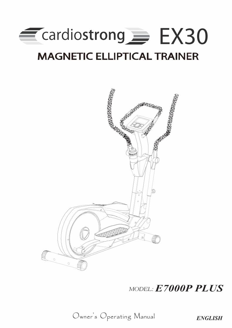
MAGNETIC ELLIPTICAL TRAINER
EX30
E7000P PLUS

- 1 -
Main frame
Monitor
TOOLS
Front stabilizer
Rear stabilizer
Centralsupport tube Front
handlebar
Sidehandlebar
Waterbottle
Handlebar joint cover Pedal tube joint cover Pedal(H1)
(H2)
(H3)
(H4)
(H5)
(H6)
(J1) Knob (J2) Screw M5x8L (J3) Screw M4x12L (J4) Washer M6
(J5) Spring washer M6 (J6) Knob (J10) Iron bracket

- 2 -
ASSEMBLY FOR REAR STABILIZER
Then, secure it with washer(C5), spring washer(C6) and nut(C7).
After you complete Figure 1 & 2,if the machine dose not sit level,you can use the adjustable end caps(C2) to compensate for uneven floors.
Then, secure it with washer(D8), spring washer(D9) and nut(D10).
ASSEMBLY FOR FRONT STABILIZER
First, remove the bolts(C4), washer(C5) and nuts(C6) from the rear stabilizer(C).Use two bolts(C4) through the rear stabilizer(C) to attach to the bracket at the back of the main frame(A).
First, remove the bolts(D7), washer(D8) and nuts(D9) from the front stabilizer(D).Use two bolts(D7) through the front stabilizer(D) to attach to the bracket at the back of the main frame(A).

- 3 -
First, remove the bolts(B21), spring washers(B14) and washer(B13) from the central support tube(B).
ASSEMBLY FOR CENTRAL SUPPORT TUBE
Step1. Connect the cable(B5) & (A15).Step2. Assemble the central support tube(B)onto the main frame(A) with bolts(B21), spring washer(B14) and washer(B13).
Attention:when pushing the tubes together make sure not to pinch the cables.
ASSEMBLY FOR MONITORStep1. Connect the sensor wire(B5 & B6) with monitor wires and put the monitor on the fixing plate.Step2. You can place the water bottle in the plastic water bottle holder.

- 4 -
Step1. Pull up right or left connect tube(A43) and adjust the suitable position which 4 holesare available when loosing the pop-pin the middle tube(B) and lower tube(A43) will be fixed securely.Step2. First, remove the bolts(G4), fromthe side handlebar(G).
ASSEMBLY FOR SIDE HANDLEBAR
contrastivedrawing for the (G4) assemblyposition.
for the (J1) assemblyposition.
Step3. Then, slide the side handlebar(G) overcentral support tube(B).Secure with bolts(G4).
** During handlebar assembly you haveto use the holes as pictured in close-upview.
Repeat step1 and 2 on left connect tube(A43).
- 5 -
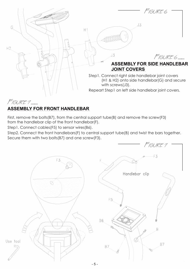
ASSEMBLY FOR FRONT HANDLEBAR
Step1. Connect right side handlebar joint covers (H1 & H2) onto side handlebar(G) and secure with screws(J3).
ASSEMBLY FOR SIDE HANDLEBAR JOINT COVERS
Repeart Step1 on left side handlebar joint covers.
First, remove the bolts(B7), from the central support tube(B) and remove the screw(F3)from the handlebar clip of the front handlebar(F).Step1. Connect cables(F5) to sensor wires(B6).Step2. Connect the front handlebars(F) to central support tube(B) and twist the bars together.Secure them with two bolts(B7) and one screw(F3).

- 6 -
798
J10
SIDE PEDAL JOINT COVERSConnect right side pedal tube joint covers(H3 & H4) onto pedal joints and secure with screws(J2).Repeat again on left side pedal tube joint covers.
ASSEMBLY FOR PEDALAssemble the iron bracket(J10) on the pedal tube and secure it by screw(J7), spring(J9) and washer(J8).Repeat again on left iron bracket(J10).Assemble the right pedal(H6) with washer(J4), spring washer(J5) and star knobs(J6).There are 3 positions for moving track.Repeat again on left pedal(H5).

- 7 -
HOW TO MOVE THE MACHINEThe front stabilizer has built-in transport wheels.
To move the machine, stand at the front and lift it up until the weight of the machine is transferred to the transport wheels.You can now easily move the machine to a new location.
(E3)Adaptor
Position Machine on consideration for convenience, using the adaptor(N), there is one adaptor hole located at the rear of the machine.
HOW TO USE THE ADAPTOR
- 8 -

- 9 -
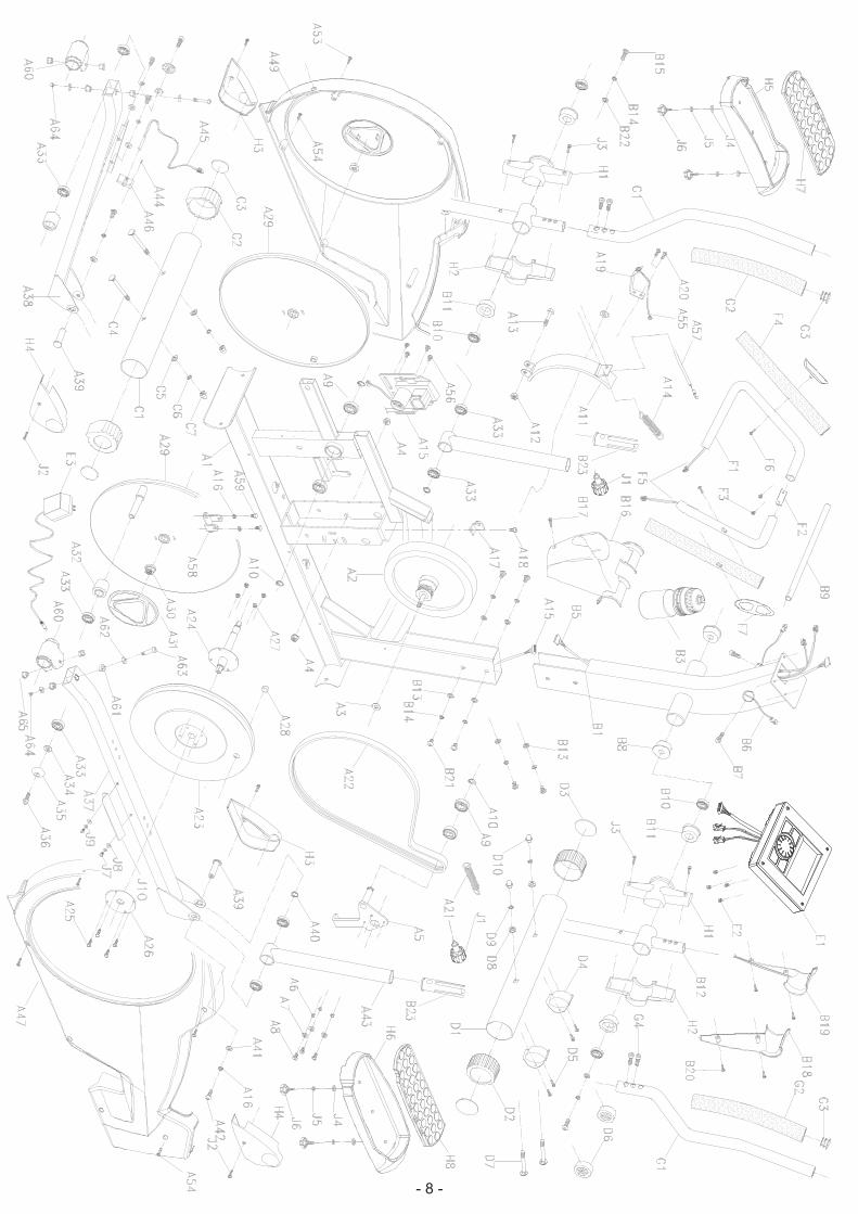
P/N DESCRIPTION P/N DESCRIPTION Q'TYQ'TYA1 MAIN FRAME 1 B1 CENTRAL SUPPOR TUBE 1A2 MAGNETIC FLYWHEEL 1 B3 WATER BOTTLE 1A3 FLAT WASHER 2 B5 SENSOR WIRE 1A4 NUT 2 B6 HAND PULSE SENSOR WIRE 2A5 TENSION PULLEY 1 B7 BOLT 2A6 PIPE 3 B8 BUSHING 2A7 FLAT WASHER 3 B9 SHAFT 1A8 SCREW 3 B10 BEARING 4A9 BEARING 4 B11 BUSHING 4A10 E CLIP 3 B12 CONNECT TUBE 2A11 MAGNETIC HOUSING 1 B13 FLAT WASHER 6A12 NUT 1 B14 SPRING WASHER 8A13 SCREW 1 B15 SCREW 2A14 SPRING 1 B16 BOTTLE HOUSING 1A15 MOTOR 1 B17 SCREW 1A16 SPRING WASHER 2 B18-B19 DECORTATION BOTTLE HOUSING 2A17 SPRING FIXING HOUSING 1 B20 SCREW 4A18 SCREW 1 B21 SCREW 6A19 FIXING HOUSING 1 B22 FLAT WASHER 2A20 SCREW 2A21 SPRING 1 C1 REAR STABILIZER 1A22 BELT 1 C2 END CAP 2A23 BELT PULLEY 1 C3 END CAP COVER 2A24 PULLEY AXLE 1 C4-D7 BOLT 4A25 SCREW 4 C5-D8 FLAT WASHER 4A26 PLANE 1 C6-D9 SPRING WASHER 4A27 NUT 4 C7-D10 NUT 4A28 MAGNET 1 D1 FRONTSTABILIZER 1A29 TURNING PALTE 2 D2 END CAP 2A30 NUT 2 D3 END CAP COVER 2A31 DECORTATION COVER 2 D4 TRANSMIT WHEEL HOUSING 2A32 PIPE 2 D5 SCREW 4A33 BEARING 4 D6 TRANSPORTATION WHEEL 2A34 FLAT WASHER 2 E1 MONITOR 1A35 SCREW COVER 2A36 SCREW 2
E3 ADAPTOR 1
A37 PEDAL TUBE(RIGHT) 1F1 FRONT HANDLE BAR(L&R)
A38 PEDLA TUBE(LEFT) 2F2 HANDLEBAR CLIP 1
A39 SCREW 2F3 SCREW 2
2
A40 FLAT WASHER 2F4 FOAM GRIP 2
A41 FLAT WASHER 2F5 SENSOR 2
A42 SCREW 2F6 SCREW 2
A43 CONNECT PIPE 2 G1 SIDE HANDLE BAR(L+R) 2A44 SCREW 1 G2 FOAM GRIP 2A45 SENSOR WIRE 1 G3 END CAP 2A46 FIXING HOUSING 1 G4 SCREW 4A47 RIGHT COVER 1 H1-H2 DECORTATION COVER 4
H3-H4 PEDAL JOINT COVER 4A49 LEFT COVER 1H5-H6 PEDAL(L+R) 1A53 SCREW 3
A54 TAPPING SCREW 6A55 POWER CORD SENSOR 1A56 SCREW 4A57 TENSION CABLE 1A58 CLIP 1A59 SCREW 2A60 CLIP 2A61 BUSHING 4A62 WASHER
BOLT4
A63 2A64 NUT 2
PARTS LIST
2BONK1J4WERCS2J4WERCS3J4REHSAWTALF4J4REHSAWGNIRPS5J4BONK6J
J7 SCREW 4J8J9 SPRING WASHER
WASHER 44
J10 IRON BRACKET 2
1D(L+R)APNOIHSUC8H-7H
F7 HANDLE PLUS 2
B23 PLASTIC INSERT 2
A65 BUSHING 4

1. LCD display (with all segments):
2. BUTTON functions:
To select training mode and adjust function value up.To start or stop exercise. To select training mode and adjust function value down.
In stop mode, the mode is to confirm all exercise data setting, and enter into program.
TOTAL RESET To power on the computer again.
In stop mode, press the button back to main menu.
3. DISPLAY function list:egnaryalpsiDmetI
TIME 0:00 ~ 99:59
SPEED 0.0~99.9 KMH0.0~99.9 MLH
RPM 0~999DISTANCE 0.0~99.9 KM (ML)CALORIES 0~999 CALPULSE P-30~230 BPMWATTS 0~999
MODE
RESET
START/STOP
RECOVERY
ENCODER UPENCODER DOWN
RESET
START / STOP
RECOVERY
TOTAL RESET
To start or stop training
To test heart rate recovery status
- 10 -

Figure 1 Figure 2
Figure 3 Figure 4
5. Select workout program P1~P12:In standby mode, turn UP and DOWN button to select workout program from P1 P2 to P12.User may also press START button to start workout in P1 mode (Manual).3-1 After select preferred program, user may press MODE to enter.
In P1 (manual mode), user shall preset TIME, DISTANCE, CALORIES and PULSE value andpress START. STOP to start workout. Resistance level may adjust during workout by turing UPand DOWN.
4. Operation Procedure:4-1 Power on: Install power supply and computer will have long beep sound and display all
segments for 2 seconds, then show wheel diameter. (as figure 1)Console will ask user to set up clock first and then enter into standby mode.
User may turn UP and DOWN button to select exercise program from P1 to P12, and pressMODE to confirm. (as figure 2 to 3)
4-2 Power off: With no signal input for over 4 minutes, LCD will off and resistance level shall returnto level 1. Console will display CLOCK and TEMP. as figure 4.
Figure 5
- 11 -

A3-2 In P2 to P11 program mode, gridyard will show corresponding profile, press MODE toENTER.User shall preset TIME and press START to start workout.Resistance level can be adjusted during workout by turning UP and DOWN.
Figure 6 Figure 7
MANUAL SELECT P1
PRESSTOTAL RESET
CLOCKWISE ORANTI-CLOCKWISE
MANUAL mode
PRESSMODE
P1
START / STOP
CLOCKWISE ORANTI-CLOCKWISE
FUNCTION SELECT
TIME
PRESSMODE
TOTAL RESET
CLOCKWISE ORANTI-CLOCKWISE
FUNCTION SELECT
DISTA
NC
E
CLOCKWISE ORANTI-CLOCKWISE
FUNCTION SELECT
PULS
E
PRESSMODE
CLOCKWISE ORANTI-CLOCKWISE
FUNCTION SELECT
CALORIES
PRESSMODE
PRESSMODE
PROGRAM SELECT P2 to P10
CLOCKWISE ORANTI-CLOCKWISE
PROGRAM mode
PRESSMODE
P2
P5
P4
P3
P6P7
P8
P9
P10
PRESSMODE
START / STOP
PRESSTOTAL RESET
TOTAL RESET
P11
CLOCKWISE ORANTI-CLOCKWISE
FUNCTION SELECT
TIME
- 12 -

PROGRAM Profile for P2 to P11:
A3-3 In P12 mode (HR control), AGE information is required to be entered.User may press UP and DOWN button to set up AGE (default is 25), and press MODE to enter.After AGE is setted, user need to select HR level from 55%, 75%, 90% or target pulse. (as figure 8and 9)
Figure 8
H.R.C SELECT P12
CLOCKWISE ORANTI-CLOCKWISE
CLOCKWISE ORANTI-CLOCKWISE
H.R.C mode
PRESSMODE
P12
AGE SET
AGE +
AGE-
PRESSMODE
TRAINING MODE SELECT
CLOCKWISE ORANTI-CLOCKWISE
. RC
%55
%57
%09
PRESSMODE
START / STOP
PRESSTOTAL RESET
TOTAL RESET
CLOCKWISE ORANTI-CLOCKWISE
FUNCTION SELECT
TIME
TRAINING MODE SELECT
CLOCKWISE ORANTI-CLOCKWISE
GAT
CLOCKWISE ORANTI-CLOCKWISE
FUNCTION SELECT
PULS
E
Figure 9
- 13 -

4. RECOVERYAfter exercising for a period of time, keep holding on handgrips and press “RECOVERY”button. All function display will stop except “TIME” starts counting down from 00:60 to 00:00.Screen will display your heart rate recovery status with the F1,F2….to F6. F1 is the best, F6F6 is the worst. User may keep exercising to improve the heart rate recovery status.(Press the RECOVERY button again to return the main display.)
NOTE:1. This computer require #2 batteries X 4pcs or 9V, 500mA or 9V, 1000mA adaptor for power supply. If console display follow battery symbol, please do plug in adaptor or change batterie
2. When user stop pedaling for 4 minutes, computer will enter into power save mode, all setting andexercise data will stored until user start exercise again.
3. When computer act abnormal, please plug out the adaptor and plug in again.
- 14 -