Magnetic effect-of-current
45
Magnetic Effect of Current 1 1 genius PHYSICS Oersted found that a magnetic field is established around a current carrying conductor. Magnetic field exists as long as there is current in the wire. The direction of magnetic field was found to be changed when direction of current was reversed. Note : A moving charge produces magnetic as well as electric field, unlike a stationary charge which only produces electric field. Biot Savart's Law. Biot-Savart’s law is used to determine the magnetic field at any point due to a current carrying conductors. This law is although for infinitesimally small conductors yet it can be used for long conductors. In order to understand the Biot-Savart’s law, we need to understand the term current-element. Current element It is the product of current and length of infinitesimal segment of current carrying wire. The current element is taken as a vector quantity. Its direction is same as the direction of current. Current element AB = dl i In the figure shown below, there is a segment of current carrying wire and P is a point where magnetic field is to be calculated. l d i is a current element and r is the distance of the point ‘P’ with respect to the current element l d i . According to Biot-Savart Law, magnetic field at point ‘P’ due to the current element l d i is given by the expression, 2 r dlsin θ i k dB also 2 0 sin . 4 r dl i dB B In C.G.S. : k = 1 2 sin r idl dB Gauss In S.I. : 4 0 k 2 0 sin 4 r idl dB Tesla where 0 = Absolute permeability of air or vacuum metre Amp Wb 7 10 4 . It's other units are metre Henry or 2 Amp N or Ampere metre Tesla dl i P r A B dl i Magnetic lines of forces i
-
Upload
jai-kumar-kaushil -
Category
Self Improvement
-
view
167 -
download
2
Transcript of Magnetic effect-of-current
Magnetic Effect of Current 1 1genius PHYSICS
Oersted found that a magnetic field is established around a current
carrying conductor.
Magnetic field exists as long as there is current in the wire.
The direction of magnetic field was found to be changed when direction of
current was reversed.
Note : A moving charge produces magnetic as well as electric field,
unlike a stationary charge which only produces electric field.
Biot Savart's Law.
Biot-Savart’s law is used to determine the magnetic field at any point due to a current carrying
conductors.
This law is although for infinitesimally small conductors yet it can be used for long conductors. In order to
understand the Biot-Savart’s law, we need to understand the term current-element.
Current element
It is the product of current and length of infinitesimal segment of current carrying wire.
The current element is taken as a vector quantity. Its direction is same as the direction of current.
Current element AB = dli
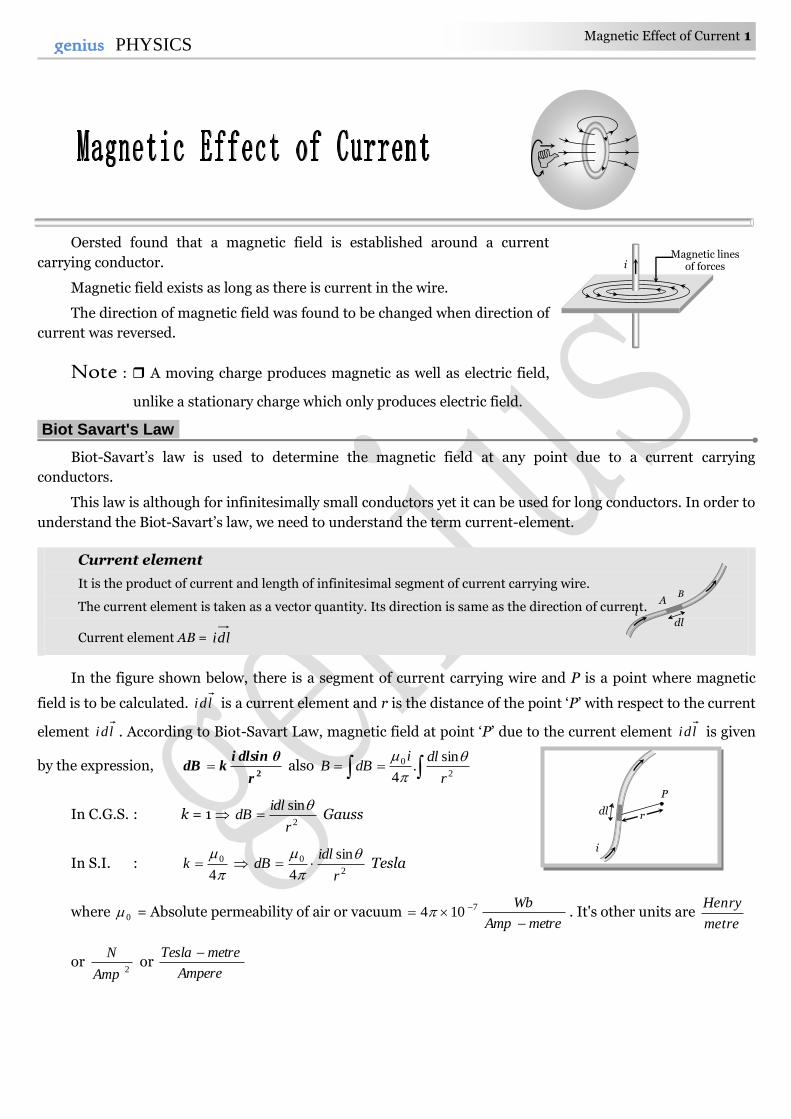
In the figure shown below, there is a segment of current carrying wire and P is a point where magnetic
field is to be calculated. ldi is a current element and r is the distance of the point ‘P’ with respect to the current
element ldi . According to Biot-Savart Law, magnetic field at point ‘P’ due to the current element ldi is given
by the expression, 2
r
dlsin θikdB also
2
0 sin.
4 r
dlidBB
In C.G.S. : k = 1 2
sin
r
idldB
Gauss
In S.I. :
4
0k 2
0 sin
4 r
idldB
Tesla
where 0 = Absolute permeability of air or vacuum metreAmp
Wb
7104 . It's other units are
metre
Henry
or 2Amp
N or
Ampere
metreTesla
dl
i
P
r
A B
dl i
Magnetic lines of forces i
2 Magnetic Effect of Current genius PHYSICS
(1) Different forms of Biot-Savarts law
Vector form Biot-Savarts law in terms of
current density
Biot-savarts law in terms of
charge and it's velocity
Vectorially,
3
0
2
0 )(
4
)ˆ(
4 r
rldi
r
rldiBd
Direction of Bd
is perpendicular to
both ld
and r . This is given by
right hand screw rule.
In terms of current density
dVr
rJBd
3
0
4
where dV
idl
Adl
idl
A
ij = current
density at any point of the element,
dV = volume of element
In terms of charge and it’s velocity,
3
0 )(
4 r
rvqBd
vqdt
ldqld
dt
qlid
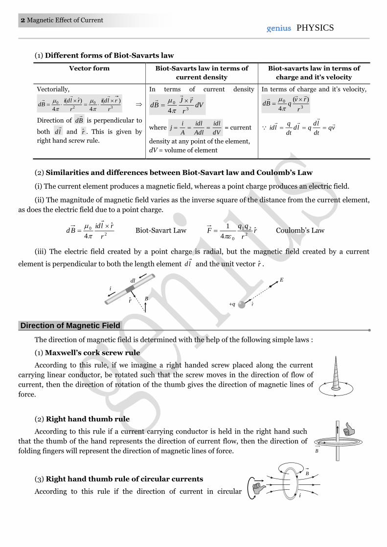
(2) Similarities and differences between Biot-Savart law and Coulomb’s Law
(i) The current element produces a magnetic field, whereas a point charge produces an electric field.
(ii) The magnitude of magnetic field varies as the inverse square of the distance from the current element,
as does the electric field due to a point charge.
2
0ˆ
4 r
rlidBd
Biot-Savart Law r
r
qqF ˆ
4
12
21
0 Coulomb’s Law
(iii) The electric field created by a point charge is radial, but the magnetic field created by a current
element is perpendicular to both the length element ld and the unit vector r .
Direction of Magnetic Field.
The direction of magnetic field is determined with the help of the following simple laws :
(1) Maxwell’s cork screw rule
According to this rule, if we imagine a right handed screw placed along the current
carrying linear conductor, be rotated such that the screw moves in the direction of flow of
current, then the direction of rotation of the thumb gives the direction of magnetic lines of
force.
(2) Right hand thumb rule
According to this rule if a current carrying conductor is held in the right hand such
that the thumb of the hand represents the direction of current flow, then the direction of
folding fingers will represent the direction of magnetic lines of force.
(3) Right hand thumb rule of circular currents
According to this rule if the direction of current in circular
B
i
B
dl
i
r B r +q
E
Magnetic Effect of Current 3 3genius PHYSICS
conducting coil is in the direction of folding fingers of right hand, then the direction of magnetic field will be in
the direction of stretched thumb.
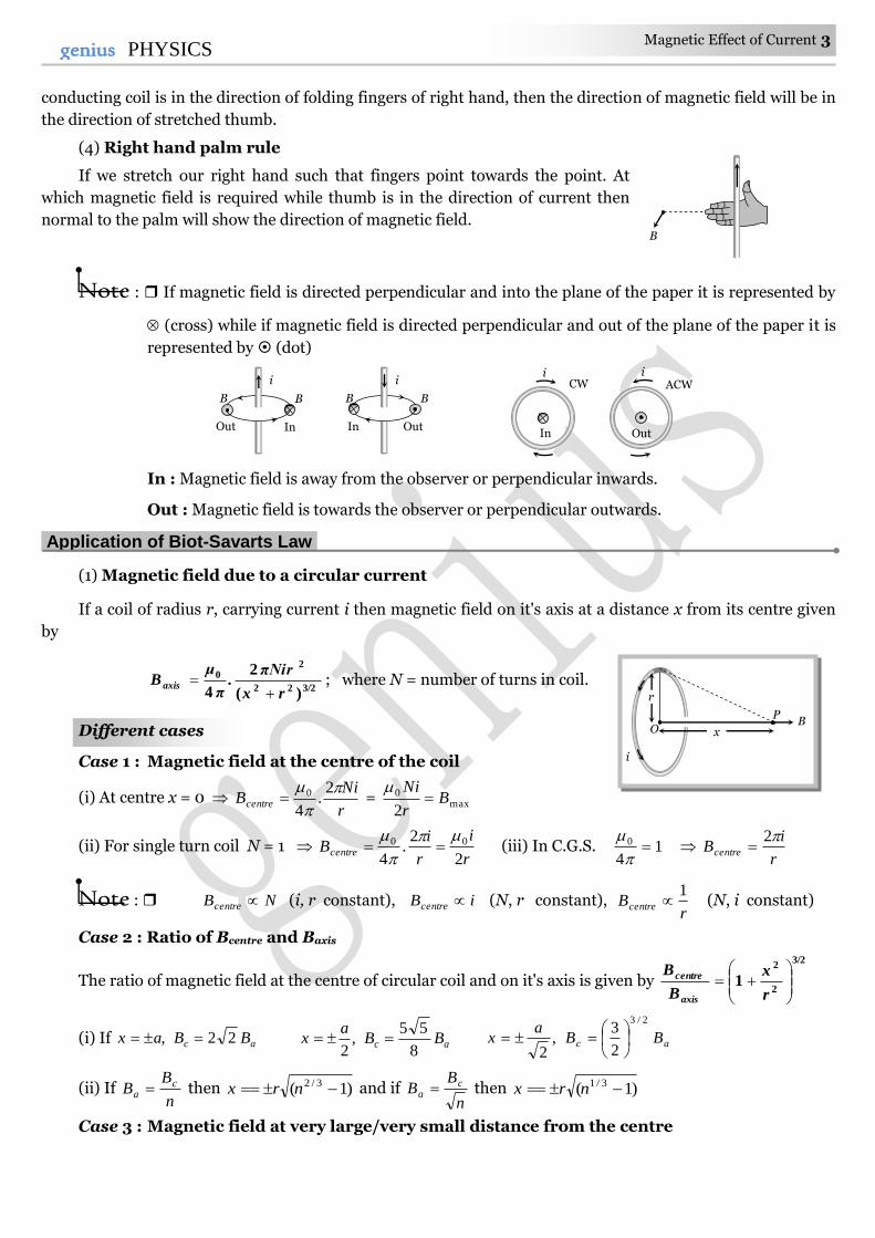
(4) Right hand palm rule
If we stretch our right hand such that fingers point towards the point. At
which magnetic field is required while thumb is in the direction of current then
normal to the palm will show the direction of magnetic field.
Note : If magnetic field is directed perpendicular and into the plane of the paper it is represented by
(cross) while if magnetic field is directed perpendicular and out of the plane of the paper it is
represented by (dot)
In : Magnetic field is away from the observer or perpendicular inwards.
Out : Magnetic field is towards the observer or perpendicular outwards.
Application of Biot-Savarts Law.
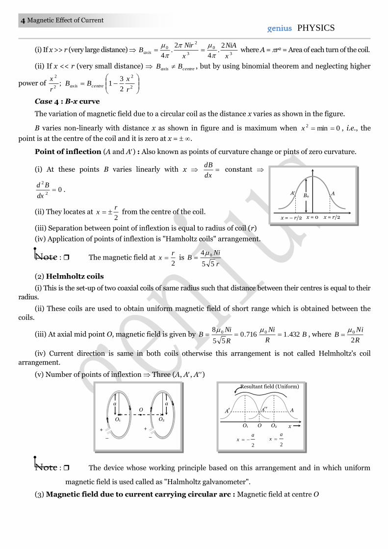
(1) Magnetic field due to a circular current
If a coil of radius r, carrying current i then magnetic field on it's axis at a distance x from its centre given
by
3/222
20
)(
2
4 rx
πNir.
μB axis
π; where N = number of turns in coil.
Different cases
Case 1 : Magnetic field at the centre of the coil
(i) At centre x = 0 r
NiBcentre
2.
4
0 = max0
2B
r
Ni
(ii) For single turn coil N = 1 r
i
r
iBcentre
2
2.
4
00
(iii) In C.G.S. 1
4
0
r
iBcentre
2
Note : NBcentre (i, r constant), iBcentre (N, r constant), r
Bcentre
1 (N, i constant)
Case 2 : Ratio of Bcentre and Baxis
The ratio of magnetic field at the centre of circular coil and on it's axis is given by
3/2
2
2
1
r
x
B
B
axis
centre
(i) If ac BBax 22, ac BBa
x8
55,
2 ac BB
ax
2/3
2
3,
2
(ii) If n
BB c
a then )1( 3/2 nrx and if n
BB c
a then )1( 3/1 nrx
Case 3 : Magnetic field at very large/very small distance from the centre
i
B B
Out In
i
B B
Out In
i CW
In
i ACW
Out
B P
x
r
i
O
B
4 Magnetic Effect of Current genius PHYSICS
(i) If x >> r (very large distance) 3
0
3
20 2
.4
2.
4 x
NiA
x
NirBaxis
where A = r2 = Area of each turn of the coil.
(ii) If x << r (very small distance) centreaxis BB , but by using binomial theorem and neglecting higher
power of ;2
2
r
x
2
2
2
31
r
xBB centreaxis
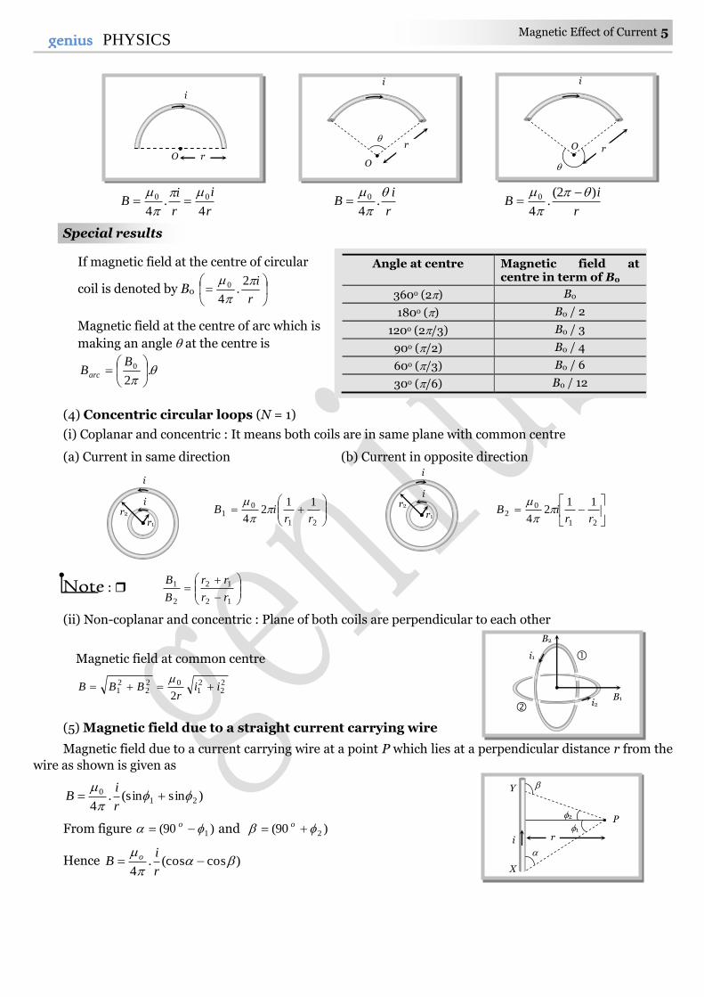
Case 4 : B-x curve
The variation of magnetic field due to a circular coil as the distance x varies as shown in the figure.
B varies non-linearly with distance x as shown in figure and is maximum when 0min2 x , i.e., the
point is at the centre of the coil and it is zero at x = .
Point of inflection (A and A) : Also known as points of curvature change or pints of zero curvature.
(i) At these points B varies linearly with x dx
dB constant
02
2
dx
Bd.
(ii) They locates at 2
rx from the centre of the coil.
(iii) Separation between point of inflextion is equal to radius of coil (r)
(iv) Application of points of inflextion is "Hamholtz coils" arrangement.
Note : The magnetic field at 2
rx is
r
NiB
55
4 0
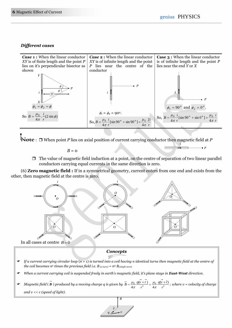
(2) Helmholtz coils
(i) This is the set-up of two coaxial coils of same radius such that distance between their centres is equal to their
radius.
(ii) These coils are used to obtain uniform magnetic field of short range which is obtained between the
coils.
(iii) At axial mid point O, magnetic field is given by BR
Ni
R
NiB 432.1716.0
55
8 00
, where R
NiB
2
0
(iv) Current direction is same in both coils otherwise this arrangement is not called Helmholtz's coil
arrangement.
(v) Number of points of inflextion Three (A, A, A)
Note : The device whose working principle based on this arrangement and in which uniform
magnetic field is used called as "Halmholtz galvanometer".
(3) Magnetic field due to current carrying circular arc : Magnetic field at centre O
A A B0
x = – r/2 x = 0 x = r/2
a
O2
O
+
–
a
O1
+
–
O x O2 O1
2
ax
2
ax
Resultant field (Uniform)
A A A
Magnetic Effect of Current 5 5genius PHYSICS
r
i
r
iB
4.
4
00
r
iB
.
4
0 r
iB
)2(.
4
0
Special results
Angle at centre Magnetic field at centre in term of B0
360o (2) B0
180o () B0 / 2
120o (2/3) B0 / 3
90o (/2) B0 / 4
60o (/3) B0 / 6
30o (/6) B0 / 12
(4) Concentric circular loops (N = 1)
(i) Coplanar and concentric : It means both coils are in same plane with common centre
(a) Current in same direction (b) Current in opposite direction
21
01
112
4 rriB
21
02
112
4 rriB
Note :
12
12
2
1
rr
rr
B
B
(ii) Non-coplanar and concentric : Plane of both coils are perpendicular to each other
Magnetic field at common centre
22
21
022
21
2ii
rBBB
(5) Magnetic field due to a straight current carrying wire
Magnetic field due to a current carrying wire at a point P which lies at a perpendicular distance r from the
wire as shown is given as
)sin(sin.4
210
r
iB
From figure )90( 1 o and )90( 2 o
Hence )cos(cos.4
r
iB o
O r
i
O
i
r
i
r
O
i
i
r1 r2
i
i
r1 r2
i2
i1
B2
B1
If magnetic field at the centre of circular
coil is denoted by B0
r
i
2.
4
0
Magnetic field at the centre of arc which is
making an angle at the centre is
.2
0
BBarc
P 2
1
i r
Y
X
6 Magnetic Effect of Current genius PHYSICS
Different cases
Case 1 : When the linear conductor XY is of finite length and the point P lies on it's perpendicular bisector as shown
21
So )sin2(.4
0
r
iB
Case 2 : When the linear conductor XY is of infinite length and the point P lies near the centre of the conductor
1 = 2 = 90o.
So,r
i
r
iB oo 2
4]90sin90[sin
4
00
Case 3 : When the linear conductor is of infinite length and the point P lies near the end Y or X
o901 and o02 .
So, r
i
r
iB oo
4]0sin90[sin
4
00
Note : When point P lies on axial position of current carrying conductor then magnetic field at P
B = 0
The value of magnetic field induction at a point, on the centre of separation of two linear parallel
conductors carrying equal currents in the same direction is zero.
(6) Zero magnetic field : If in a symmetrical geometry, current enters from one end and exists from the
other, then magnetic field at the centre is zero.
In all cases at centre 0B
Concepts
If a current carrying circular loop (n = 1) is turned into a coil having n identical turns then magnetic field at the centre of
the coil becomes n2 times the previous field i.e. B (n turn) = n2 B(single turn)
When a current carrying coil is suspended freely in earth's magnetic field, it's plane stays in East-West direction.
Magnetic field ( B ) produced by a moving charge q is given by 2
0
3
0 )ˆ(
4
)(
4 r
rvq
r
rvqB
; where v = velocity of charge
and v << c (speed of light).
i
O
i
O O
O O
P i
q v r
B
O
P
i r
Y
X
P
i
P
i
Magnetic Effect of Current 7 7genius PHYSICS
If an electron is revolving in a circular path of radius r with speed v then magnetic field produced at the centre of circular
path 2
0 .4 r
evB
.
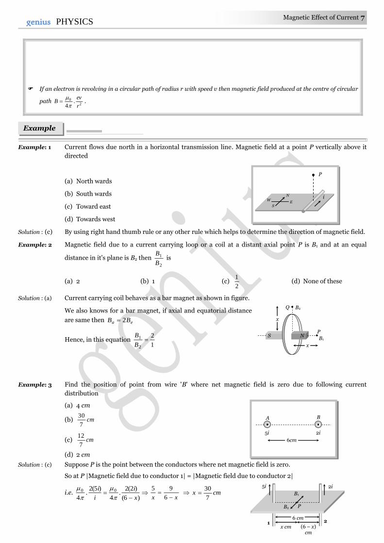
Example: 1 Current flows due north in a horizontal transmission line. Magnetic field at a point P vertically above it
directed
(a) North wards
(b) South wards
(c) Toward east
(d) Towards west
Solution : (c) By using right hand thumb rule or any other rule which helps to determine the direction of magnetic field.
Example: 2 Magnetic field due to a current carrying loop or a coil at a distant axial point P is B1 and at an equal
distance in it's plane is B2 then 2
1
B
B is
(a) 2 (b) 1 (c) 2
1 (d) None of these
Solution : (a) Current carrying coil behaves as a bar magnet as shown in figure.
We also knows for a bar magnet, if axial and equatorial distance
are same then ea BB 2
Hence, in this equation 1
2
2
1 B
B
Example: 3 Find the position of point from wire 'B' where net magnetic field is zero due to following current
distribution
(a) 4 cm
(b) cm7
30
(c) cm7
12
(d) 2 cm
Solution : (c) Suppose P is the point between the conductors where net magnetic field is zero.
So at P |Magnetic field due to conductor 1| = |Magnetic field due to conductor 2|
i.e. )6(
)2(2.
4
)5(2.
4
00
x
i
i
i
xx
6
95 cmx
7
30
Examples
x
Q B2
P
B1
x
S N
5i
1 2
P B2
B1
2i
6 cm
x cm (6 – x) cm
N
E W
S
P
i
A B
5i 2i
6cm
8 Magnetic Effect of Current genius PHYSICS
Hence position from B cm7
12
7
306
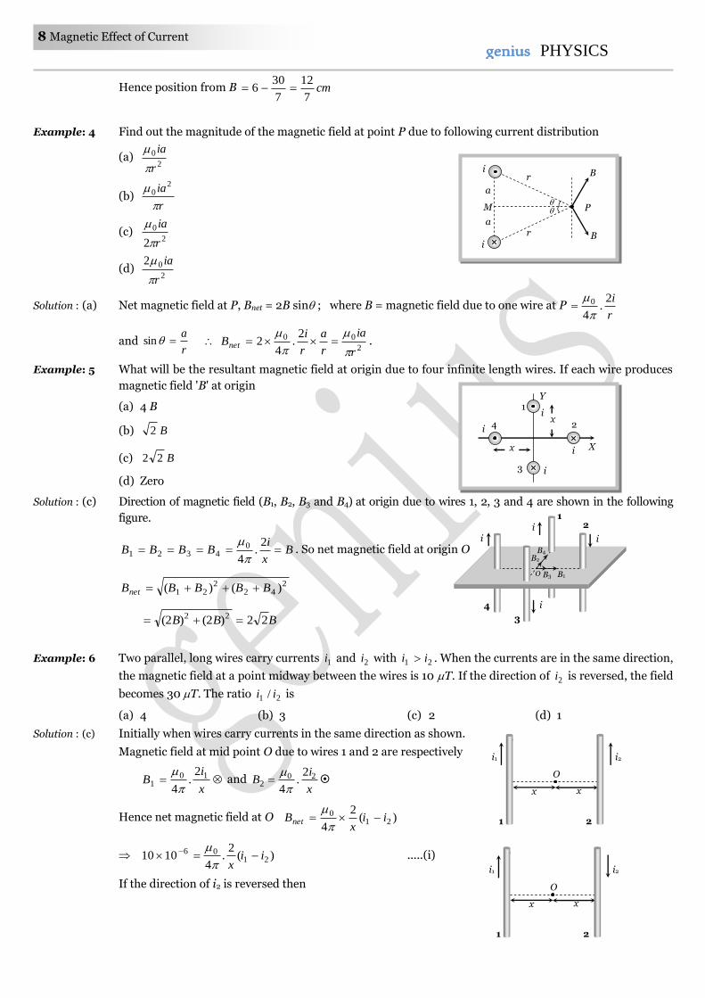
Example: 4 Find out the magnitude of the magnetic field at point P due to following current distribution
(a) 2
0
r
ia
(b) r
ia
20
(c) 2
0
2 r
ia
(d) 2
02
r
ia
Solution : (a) Net magnetic field at P, Bnet = 2B sin ; where B = magnetic field due to one wire at P r
i2.
4
0
and r
asin
2
00 2.
42
r
ia
r
a
r
iBnet
.
Example: 5 What will be the resultant magnetic field at origin due to four infinite length wires. If each wire produces
magnetic field 'B' at origin
(a) 4 B
(b) B2
(c) B22
(d) Zero
Solution : (c) Direction of magnetic field (B1, B2, B3 and B4) at origin due to wires 1, 2, 3 and 4 are shown in the following
figure.
Bx
iBBBB
2.
4
04321
. So net magnetic field at origin O
242
221 )()( BBBBBnet
BBB 22)2()2( 22
Example: 6 Two parallel, long wires carry currents 1i and 2i with 21 ii . When the currents are in the same direction,
the magnetic field at a point midway between the wires is 10 T. If the direction of 2i is reversed, the field
becomes 30 T. The ratio 21 / ii is
(a) 4 (b) 3 (c) 2 (d) 1
Solution : (c) Initially when wires carry currents in the same direction as shown.
Magnetic field at mid point O due to wires 1 and 2 are respectively
x
iB 10
1
2.
4
and
x
iB 20
2
2.
4
Hence net magnetic field at O )(2
421
0 iix
Bnet
)(2
.4
1010 2106 ii
x
.....(i)
If the direction of i2 is reversed then
4
3
i
i i
i
O
1 2
B4
B1 B3
B2
O
x x
i1 i2
1 2
O
x x
i1 i2
1 2
a
a
M
i
i B
B
r
r
P
x
1 Y
X
4
3
2
i
i
i
i x
Magnetic Effect of Current 9 9genius PHYSICS
x
iB 10
1
2.
4
and
x
iB 20
2
2.
4
So )(2
.4
210 ii
xBnet
)(
2.
41030 21
06 iix
......(ii)
Dividing equation (ii) by (i) 1
3
21
21
ii
ii
1
2
2
1 i
i
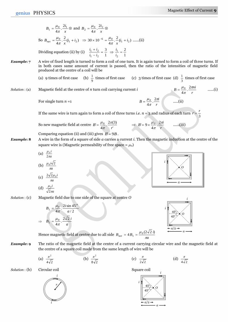
Example: 7 A wire of fixed length is turned to form a coil of one turn. It is again turned to form a coil of three turns. If in both cases same amount of current is passed, then the ratio of the intensities of magnetic field produced at the centre of a coil will be [MP PMT 2002]
(a) 9 times of first case (b) 9
1 times of first case (c) 3 times of first case (d)
3
1 times of first case
Solution : (a) Magnetic field at the centre of n turn coil carrying current i r
niB
2.
4
0 ......(i)
For single turn n =1 r
iB
2.
4
0 .....(ii)
If the same wire is turn again to form a coil of three turns i.e. n = 3 and radius of each turn 3
'r
r
So new magnetic field at centre '
)3(2.
4' 0
rB
r
iB
2.
49' 0 ......(iii)
Comparing equation (ii) and (iii) gives BB 9' .
Example: 8 A wire in the form of a square of side a carries a current i. Then the magnetic induction at the centre of the
square wire is (Magnetic permeability of free space = 0) [EAMCET 2001]
(a) a
i
2
0
(b) a
i
20
(c) a
i
022
(d) a
i
2
0
Solution : (c) Magnetic field due to one side of the square at centre O
2/
45sin2.
4
01
a
iB
o
a
iB
22.
4
01
Hence magnetic field at centre due to all side a
iBBnet
)22(4 0
1
Example: 9 The ratio of the magnetic field at the centre of a current carrying circular wire and the magnetic field at
the centre of a square coil made from the same length of wire will be
(a) 24
2 (b)
28
2 (c)
22
(d)
24
Solution : (b) Circular coil Square coil
i
i
r
45o
45o O
i
a/2 a
i
45o
45o O
i
a/2 a
i
O
i
a
10 Magnetic Effect of Current genius PHYSICS
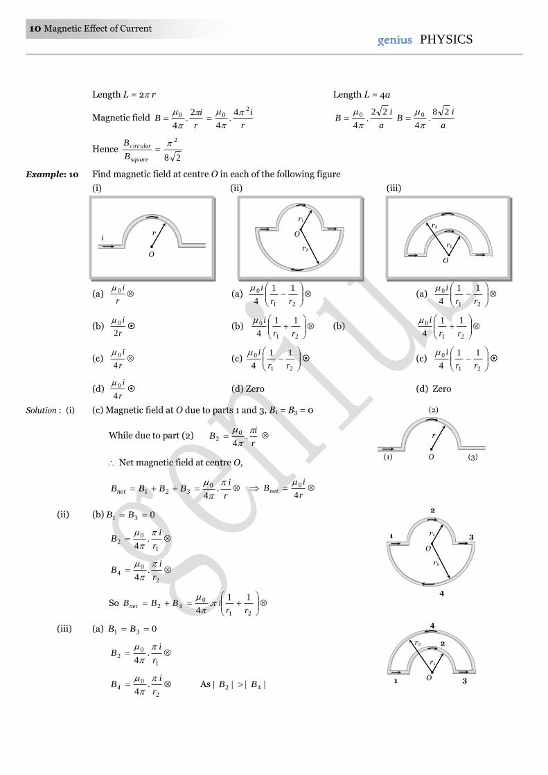
Length L = 2 r Length L = 4a
Magnetic field r
iB
2.
4
0r
i20 4
.4
a
iB
22.
4
0
a
iB
28.
4
0
Hence 28
2
square
circular
B
B
Example: 10 Find magnetic field at centre O in each of the following figure
(i) (ii) (iii)
(a) r
i0 (a)
21
0 11
4 rr
i (a)
21
0 11
4 rr
i
(b) r
i
2
0 (b)
21
0 11
4 rr
i (b)
21
0 11
4 rr
i
(c) r
i
4
0 (c)
21
0 11
4 rr
i (c)
21
0 11
4 rr
i
(d) r
i
4
0 (d) Zero (d) Zero
Solution : (i) (c) Magnetic field at O due to parts 1 and 3, B1 = B3 = 0
While due to part (2) r
iB
.
4
02
Net magnetic field at centre O,
r
iBBBBnet
.
4
0321
r
iBnet
4
0
(ii) (b) 031 BB
1
02 .
4 r
iB
2
04 .
4 r
iB
So
21
042
11.
4 rriBBBnet
(iii) (a) 031 BB
1
02 .
4 r
iB
2
04 .
4 r
iB
As |||| 42 BB
r i
O
r
O (1)
(2)
(3)
r1
O
r2
1
2
3 r1
O
r2
4
r1
O
r2
r1
O
r2 2
1 3
4
Magnetic Effect of Current 11 11genius PHYSICS
So
21
042
11
4 rr
iBBBB netnet
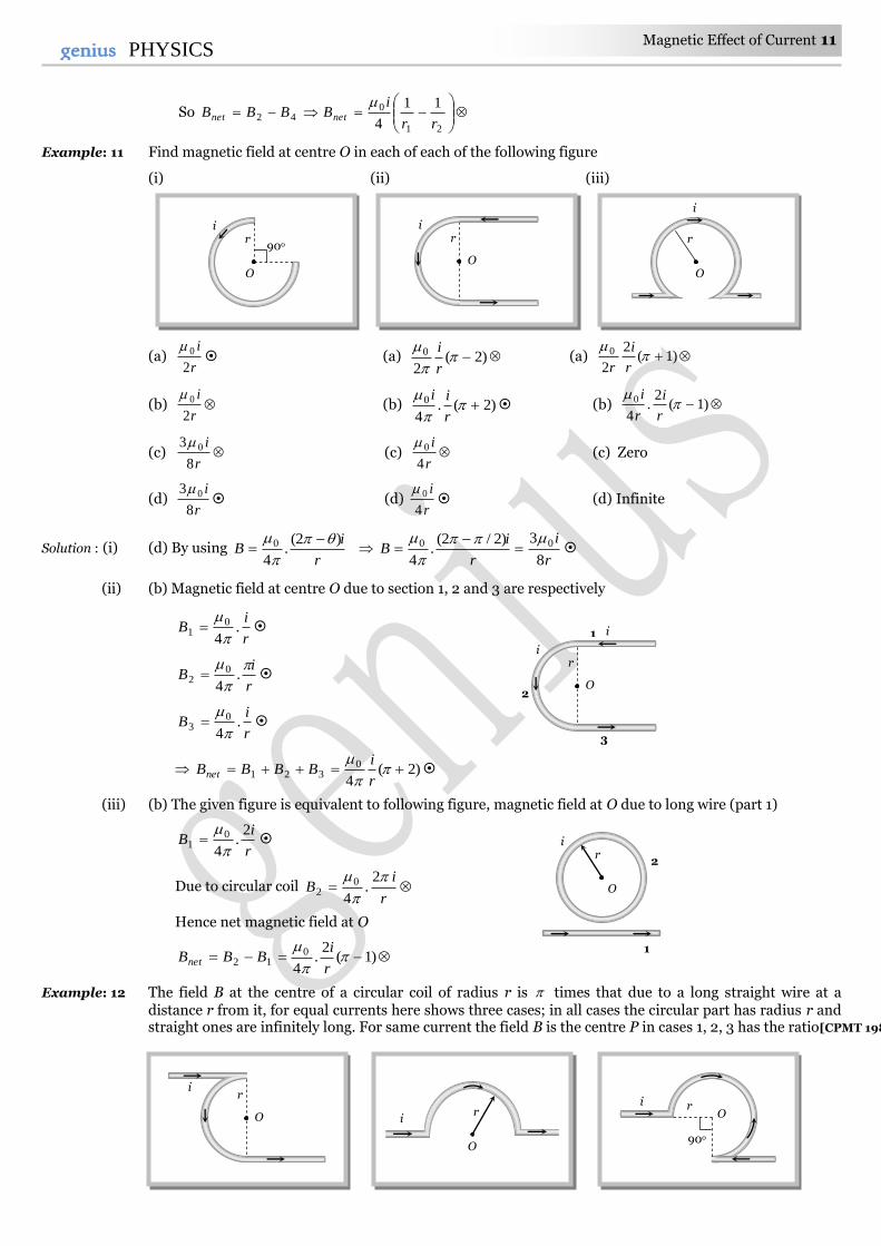
Example: 11 Find magnetic field at centre O in each of each of the following figure
(i) (ii) (iii)
(a) r
i
2
0 (a) )2(
2
0
r
i (a) )1(
2
2
0
r
i
r
(b) r
i
2
0 (b) )2(.
4
0
r
ii (b) )1(
2.
4
0
r
i
r
i
(c) r
i
8
3 0 (c) r
i
4
0 (c) Zero
(d) r
i
8
3 0 (d)
r
i
4
0 (d) Infinite
Solution : (i) (d) By using r
iB
)2(.
4
0
r
i
r
iB
8
3)2/2(.
4
00
(ii) (b) Magnetic field at centre O due to section 1, 2 and 3 are respectively
r
iB .
4
01
r
iB
.
4
02
r
iB .
4
03
)2(4
0321
r
iBBBBnet
(iii) (b) The given figure is equivalent to following figure, magnetic field at O due to long wire (part 1)
r
iB
2.
4
01
Due to circular coil r
iB
2.
4
02
Hence net magnetic field at O
)1(2
.4
012
r
iBBBnet
Example: 12 The field B at the centre of a circular coil of radius r is times that due to a long straight wire at a distance r from it, for equal currents here shows three cases; in all cases the circular part has radius r and straight ones are infinitely long. For same current the field B is the centre P in cases 1, 2, 3 has the ratio[CPMT 1989]
r
O
i
90o r
i
O
r
O
i
1 i
r i
O 2
3
r i
O r
O
i O
90o
r i
r
O
i
1
2
12 Magnetic Effect of Current genius PHYSICS
(1) (2) (3)
(a)
2
1
4
3:
2:
2
(b)
2
1
4
3:1
2:1
2
(c) 4
3:
2:
2
(d)
2
1
4
3:
2
1
2:1
2
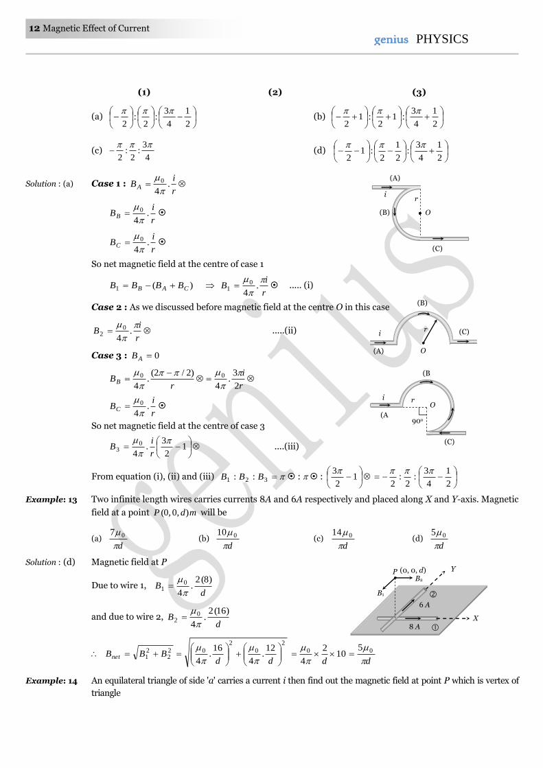
Solution : (a) Case 1 : r
iBA .
4
0
r
iBB .
4
0
r
iBC .
4
0
So net magnetic field at the centre of case 1
)(1 CAB BBBB r
iB
.
4
01 ..... (i)
Case 2 : As we discussed before magnetic field at the centre O in this case
r
iB
.
4
02 .....(ii)
Case 3 : 0AB
r
BB
)2/2(.
4
0
r
i
2
3.
4
0
r
iBC .
4
0
So net magnetic field at the centre of case 3
1
2
3.
4
03
r
iB ....(iii)
From equation (i), (ii) and (iii) 321 :: BBB : :
1
2
3
2
1
4
3:
2:
2
Example: 13 Two infinite length wires carries currents 8A and 6A respectively and placed along X and Y-axis. Magnetic
field at a point mdP ),0,0( will be
(a) d
07 (b)
d
010 (c)
d
014 (d)
d
05
Solution : (d) Magnetic field at P
Due to wire 1, d
B)8(2
.4
01
and due to wire 2, d
B)16(2
.4
02
2
0
2
022
21
12.
4
16.
4
ddBBBnet
dd
00 510
2
4
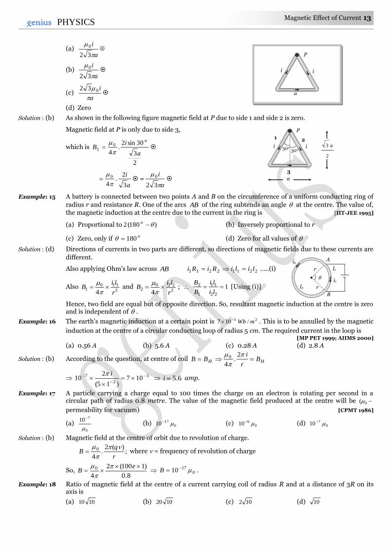
Example: 14 An equilateral triangle of side 'a' carries a current i then find out the magnetic field at point P which is vertex of
triangle
O
90o
r
(B)
i
(C)
(A)
(A)
r i
O (B)
(C)
r
O
i (C)
(B)
(A)
P
B1
B2
Y
X
(0, 0, d)
6 A
8 A
Magnetic Effect of Current 13 13genius PHYSICS
(a) a
i
32
0
(b) a
i
32
0
(c) a
i
032
(d) Zero
Solution : (b) As shown in the following figure magnetic field at P due to side 1 and side 2 is zero.
Magnetic field at P is only due to side 3,
which is
2
3
30sin2.
4
01
a
iB
o
a
i
3
2.
4
0
=
a
i
32
0
Example: 15 A battery is connected between two points A and B on the circumference of a uniform conducting ring of
radius r and resistance R. One of the arcs AB of the ring subtends an angle at the centre. The value of, the magnetic induction at the centre due to the current in the ring is [IIT-JEE 1995]
(a) Proportional to )180(2 o (b) Inversely proportional to r
(c) Zero, only if o180 (d) Zero for all values of
Solution : (d) Directions of currents in two parts are different, so directions of magnetic fields due to these currents are
different.
Also applying Ohm's law across AB 22112211 liliRiRi …..(i)
Also 2110
14 r
liB
and
2220
24 r
liB
; 1
22
11
1
2 li
li
B
B [Using (i)]
Hence, two field are equal but of opposite direction. So, resultant magnetic induction at the centre is zero and is independent of .
Example: 16 The earth’s magnetic induction at a certain point is 25 /107 mWb . This is to be annulled by the magnetic
induction at the centre of a circular conducting loop of radius 5 cm. The required current in the loop is [MP PET 1999; AIIMS 2000]
(a) 0.56 A (b) 5.6 A (c) 0.28 A (d) 2.8 A
Solution : (b) According to the question, at centre of coil HH Br
iBB
2.
4
0
5
2
7 107)15(
210
i
6.5i amp.
Example: 17 A particle carrying a charge equal to 100 times the charge on an electron is rotating per second in a circular path of radius 0.8 metre. The value of the magnetic field produced at the centre will be 0(
permeability for vacuum) [CPMT 1986]
(a) 0
710
(b) 01710 (c) 0
610 (d) 0710
Solution : (b) Magnetic field at the centre of orbit due to revolution of charge.
;)(2
.4
0
r
qB
where = frequency of revolution of charge
So, 8.0
)1100(2
4
0
eB
0
1710 B .
Example: 18 Ratio of magnetic field at the centre of a current carrying coil of radius R and at a distance of 3R on its axis is
(a) 1010 (b) 1020 (c) 102 (d) 10
r
r
i2 A
l2
B
l1
i1
P
i i
3
30o 30o
1 2
a
2
3 a
P
i
a
i
14 Magnetic Effect of Current genius PHYSICS
Solution : (a) By using ;1
2/3
2
2
r
x
B
B
axis
centre where x = 3R and r = R 1010)10( 2/3 axis
centre
B
B.
Example: 19 A circular current carrying coil has a radius R. The distance from the centre of the coil on the axis where
the magnetic induction will be th8
1 to its value at the centre of the coil, is [MP PMT 1997]
(a) 3
R (b) 3R (c) R32 (d) R
3
2
Solution : (b) By using
2/3
2
2
1
r
x
B
B
axis
centre , given r = R and centreaxis BB8
1
2/3
2
2
18
R
x
32/1
2
22 1)2(
R
x
2/1
2
2
12
R
x
2
2
14R
x Rx 3
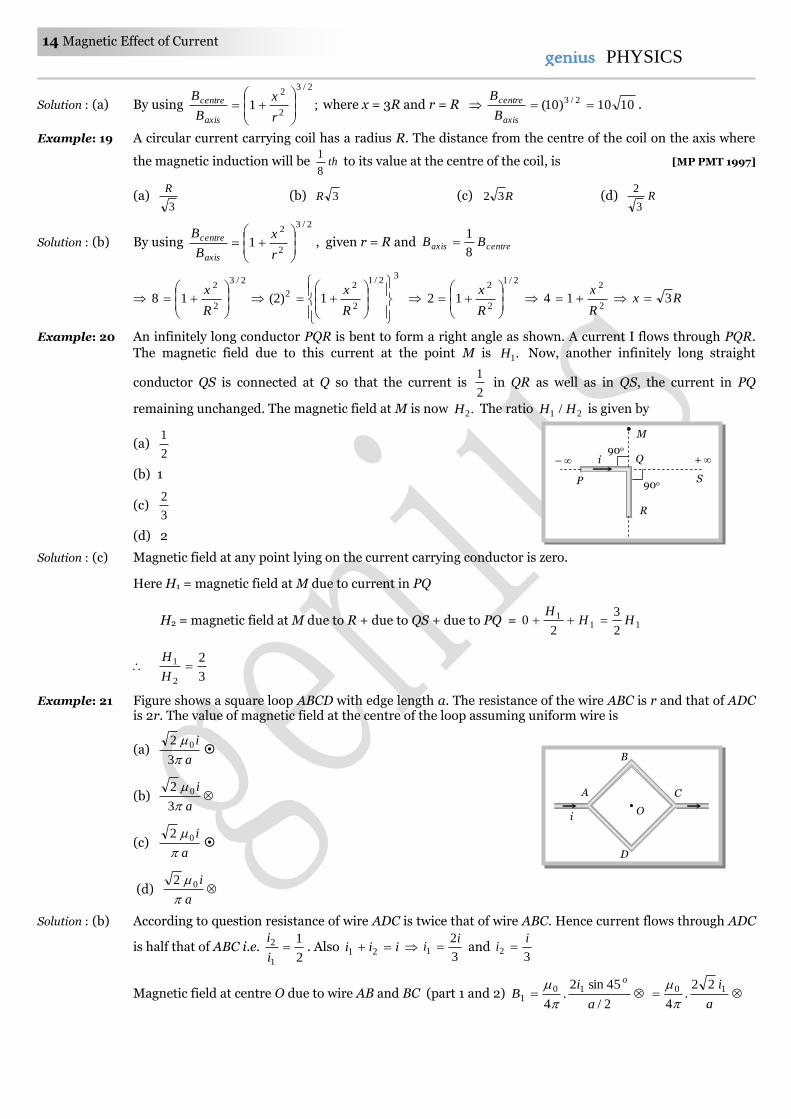
Example: 20 An infinitely long conductor PQR is bent to form a right angle as shown. A current I flows through PQR.
The magnetic field due to this current at the point M is .1H Now, another infinitely long straight
conductor QS is connected at Q so that the current is 2
1 in QR as well as in QS, the current in PQ
remaining unchanged. The magnetic field at M is now .2H The ratio 21 / HH is given by [IIT-JEE (Screening) 1999]
(a) 2
1
(b) 1
(c) 3
2
(d) 2
Solution : (c) Magnetic field at any point lying on the current carrying conductor is zero.
Here H1 = magnetic field at M due to current in PQ
H2 = magnetic field at M due to R + due to QS + due to PQ = 111
2
3
20 HH
H
3
2
2
1 H
H
Example: 21 Figure shows a square loop ABCD with edge length a. The resistance of the wire ABC is r and that of ADC is 2r. The value of magnetic field at the centre of the loop assuming uniform wire is
(a) a
i
3
2 0
(b) a
i
3
2 0
(c) a
i
02
(d) a
i
02
Solution : (b) According to question resistance of wire ADC is twice that of wire ABC. Hence current flows through ADC
is half that of ABC i.e. 2
1
1
2 i
i. Also iii 21
3
21
ii and
32
ii
Magnetic field at centre O due to wire AB and BC (part 1 and 2) 2/
45sin2.
4
101
a
iB
o
a
i10 22.
4
i
D
B
C A
O
M
P
i +
S
R
–
90o
90o Q
Magnetic Effect of Current 15 15genius PHYSICS
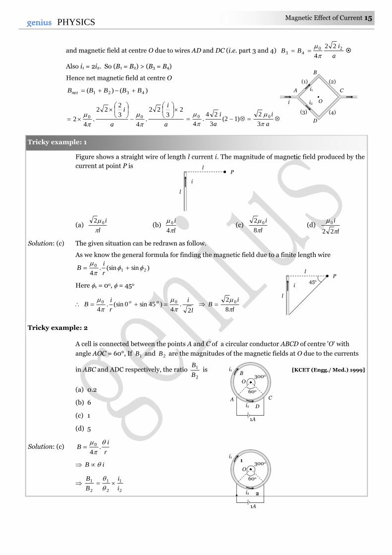
and magnetic field at centre O due to wires AD and DC (i.e. part 3 and 4) a
iBB 20
43
22
4
Also i1 = 2i2. So (B1 = B2) > (B3 = B4)
Hence net magnetic field at centre O
)()( 4321 BBBBBnet
a
i
a
i 23
22
.4
3
222
.4
2 00
a
i
a
i
3
2)12(
3
24.
4
00
Figure shows a straight wire of length l current i. The magnitude of magnetic field produced by the
current at point P is
(a) l
i
02 (b)
l
i
4
0 (c) l
i
8
2 0 (d) l
i
22
0
Solution: (c) The given situation can be redrawn as follow.
As we know the general formula for finding the magnetic field due to a finite length wire
)sin(sin.4
210
r
iB
Here 1 = 0o, = 45o
l
i
r
iB oo
2.
4)45sin0(sin.
4
00
l
iB
8
2 0
A cell is connected between the points A and C of a circular conductor ABCD of centre 'O' with
angle AOC = 60°, If 1B and 2B are the magnitudes of the magnetic fields at O due to the currents
in ABC and ADC respectively, the ratio 2
1
B
B is [KCET (Engg./ Med.) 1999]
(a) 0.2
(b) 6
(c) 1
(d) 5
Solution: (c) r
iB
.
4
0
iB
2
1
2
1
2
1
i
i
B
B
Tricky example: 2
Tricky example: 1
l
i
l
P 45o
l
i
l
P
i
D
B
C A
(1) (2)
(3) (4)
i1
i2 O
1A
i2
300o 1
2
60o
i1
O
1A
i2
300o B
C A
D
60o
i1
O
16 Magnetic Effect of Current genius PHYSICS
Also 1
2
1
2
2
1
l
l
i
i Hence
1
1
2
1 B
B
Amperes Law.
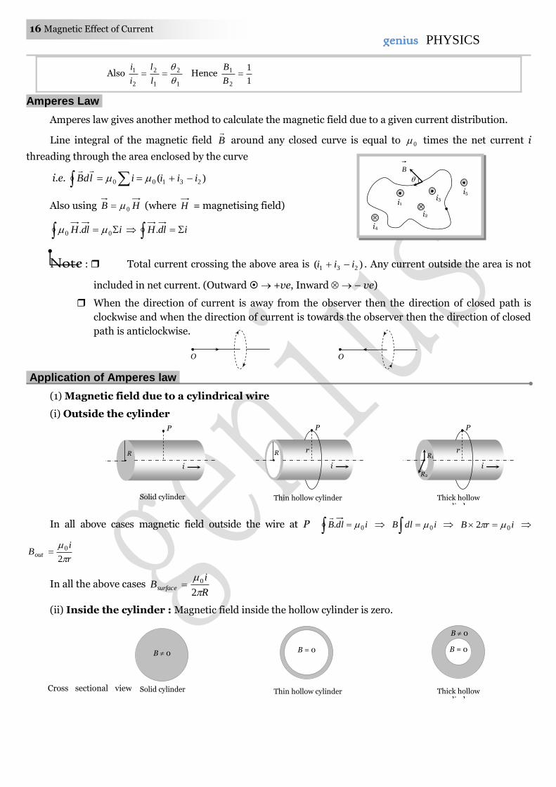
Amperes law gives another method to calculate the magnetic field due to a given current distribution.
Line integral of the magnetic field B
around any closed curve is equal to 0 times the net current i
threading through the area enclosed by the curve
i.e. )( 23100 iiiildB
Also using HB 0 (where H = magnetising field)
idlH 00 . idlH .
Note : Total current crossing the above area is )( 231 iii . Any current outside the area is not
included in net current. (Outward +ve, Inward – ve)
When the direction of current is away from the observer then the direction of closed path is
clockwise and when the direction of current is towards the observer then the direction of closed
path is anticlockwise.
Application of Amperes law.
(1) Magnetic field due to a cylindrical wire
(i) Outside the cylinder
In all above cases magnetic field outside the wire at P idlB 0.
idlB 0 irB 02
r
iBout
2
0
In all the above cases R
iBsurface
2
0
(ii) Inside the cylinder : Magnetic field inside the hollow cylinder is zero.
O O
R
i
P
Solid cylinder
R
i
P
r
Thin hollow cylinder
R1
i
P
r
R2
Thick hollow cylinder
B 0
Solid cylinder
B = 0
Thin hollow cylinder
B = 0
B 0
Thick hollow cylinder
Cross sectional view
i1
i2
i3
i5
i4
B
Magnetic Effect of Current 17 17genius PHYSICS
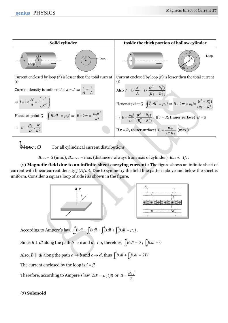
Solid cylinder Inside the thick portion of hollow cylinder
Current enclosed by loop (i) is lesser then the total current (i)
Current density is uniform i.e. J = J '
'
A
i
A
i
2
2''
R
ri
A
Aii
Hence at point Q '. 0ildB 2
202R
irrB
2
0 .2 R
irB
Current enclosed by loop (i) is lesser then the total current (i)
Also )(
)(''
21
22
21
2
RR
Rri
A
Aii
Hence at point Q '. 0 ildB )(
)(2
21
22
21
2
0RR
RrirB
)(
)(.
2 21
22
21
20
RR
Rr
r
iB
. If r = R1 (inner surface) B = 0
If r = R2 (outer surface) 2
0
2 R
iB
(max.)
Note : For all cylindrical current distributions
Baxis = 0 (min.), Bsurface = max (distance r always from axis of cylinder), Bout 1/r.
(2) Magnetic field due to an infinite sheet carrying current : The figure shows an infinite sheet of
current with linear current density j (A/m). Due to symmetry the field line pattern above and below the sheet is
uniform. Consider a square loop of side l as shown in the figure.
According to Ampere’s law, idlBdlBdlBdlBa
d
d
c
c
b
b
a0.... .
Since B dl along the path b c and d a, therefore, 0. c
bdlB ; 0.
a
ddlB
Also, B || dl along the path a b and c d, thus BldlBdlBa
d
b
a2..
The current enclosed by the loop is i = jl
Therefore, according to Ampere’s law )(2 0 jlBl or 2
0 jB
(3) Solenoid
r Loop
i
R r
Loop
i
P
a b
l
c d
B
l
Q
R1
R2
Loop
18 Magnetic Effect of Current genius PHYSICS
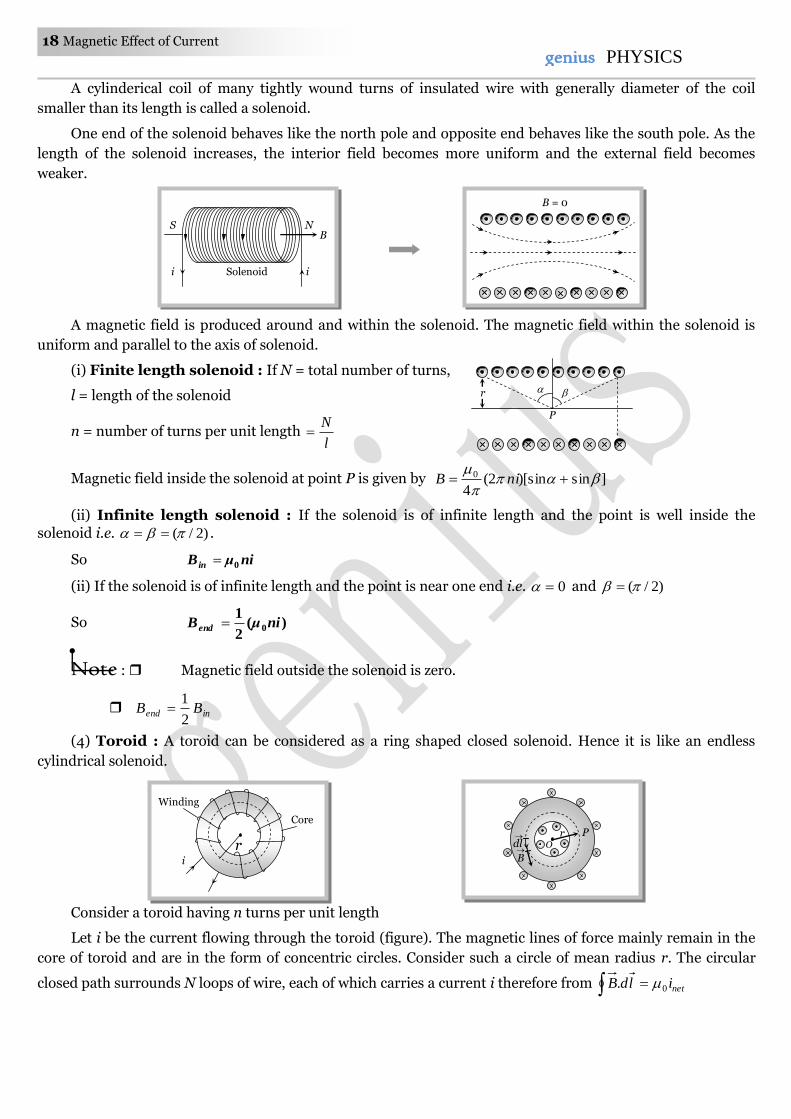
A cylinderical coil of many tightly wound turns of insulated wire with generally diameter of the coil
smaller than its length is called a solenoid.
One end of the solenoid behaves like the north pole and opposite end behaves like the south pole. As the
length of the solenoid increases, the interior field becomes more uniform and the external field becomes
weaker.
A magnetic field is produced around and within the solenoid. The magnetic field within the solenoid is
uniform and parallel to the axis of solenoid.
(i) Finite length solenoid : If N = total number of turns,
l = length of the solenoid
n = number of turns per unit length l
N
Magnetic field inside the solenoid at point P is given by ]sin)[sin2(4
0
niB
(ii) Infinite length solenoid : If the solenoid is of infinite length and the point is well inside the
solenoid i.e. )2/( .
So niμB in 0
(ii) If the solenoid is of infinite length and the point is near one end i.e. 0 and )2/(
So )(2
10niμBend
Note : Magnetic field outside the solenoid is zero.
inend BB2
1
(4) Toroid : A toroid can be considered as a ring shaped closed solenoid. Hence it is like an endless
cylindrical solenoid.
Consider a toroid having n turns per unit length
Let i be the current flowing through the toroid (figure). The magnetic lines of force mainly remain in the
core of toroid and are in the form of concentric circles. Consider such a circle of mean radius r. The circular
closed path surrounds N loops of wire, each of which carries a current i therefore from netildB 0.
B
N S
i i Solenoid
B = 0
P
r
r
Core
Winding
i
O
r
B
dl
P
Magnetic Effect of Current 19 19genius PHYSICS
NirB 0)2( nir
NiB o
2
0 where r
Nn
2
For any point inside the empty space surrounded by toroid and outside the toroid, magnetic field B is zero
because the net current enclosed in these spaces is zero.
Concepts
The line integral of magnetising field )(H for any closed path called magnetomotive force (MMF). It's S.I. unit is amp.
Ratio of dimension of e.m.f. to MMF is equal to the dimension of resistance.
Biot-Savart law is valid for asymmetrical current distributions while Ampere's law is valid for symmetrical current
distributions.
Biot-Savart law is based only on the principle of magnetism while Ampere's laws is based on the principle of
electromagnetism.
Example: 22 A long solenoid has 200 turns per cm and carries a current of 2.5 A. The magnetic field at its centre is
[0 = 4 10–7 Wb/m2] [MP PET 2000]
(a) 3.14 10–2 Wb/m2 (b) 6.28 10–2 Wb/m2 (c) 9.42 10–2 Wb/m2 (d) 12.56 10–2 Wb/m2
Solution : (b) 22
2
70 /1028.65.2
10
200104 mWbniB
.
Example: 23 A long solenoid is formed by winding 20 turns/cm. The current necessary to produce a magnetic field of
20 mili tesla inside the solenoid will be approximately
amperemetreTesla /-10
4
70
[MP PMT 1994]
(a) 8.0 A (b) 4.0 A (c) 2.0 A (d) 1.0 A
Solution : (a) niB 0 ; where cm
turnn
10
20 =
m
turn2000 . So, 51020 i 20004 .8Ai
Example: 24 Two solenoids having lengths L and 2L and the number of loops N and 4N, both have the same current,
then the ratio of the magnetic field will be [CPMT 1994]
(a) 2:1 (b) 1:2 (c) 4:1 (d) 1:4
Solution : (a) iL
NB 0
L
NB .
2
12
41
2
2
1
2
1 L
l
N
N
L
L
N
N
B
B
Example: 25 The average radius of a toroid made on a ring of non-magnetic material is 0.1 m and it has 500 turns. If it
carries 0.5 ampere current, then the magnetic field produced along its circular axis inside the toroid will
be
(a) 21025 Tesla (b) 2105 Tesla (c) 41025 Tesla (d) 4105 Tesla
Solution : (d) niB 0 ; where R
Nn
2 5.0
1.02
500104 7
B .105 4 T
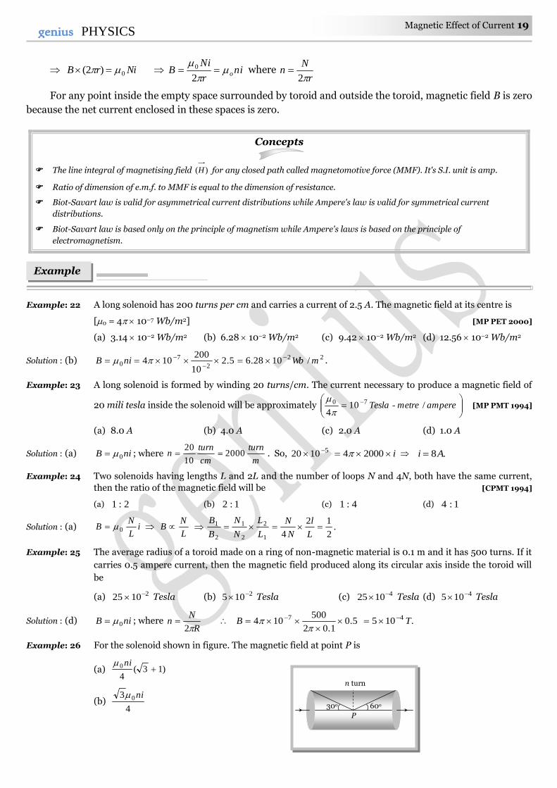
Example: 26 For the solenoid shown in figure. The magnetic field at point P is
(a) )13(4
0 ni
(b) 4
3 0ni
Examples
n turn
30o 60o
P
20 Magnetic Effect of Current genius PHYSICS
(c) )13(2
0 ni
(d) )13(4
0 ni
Solution : (a) )sin(sin2.4
0
niB . From figure = (90o – 30o) = 60o and = (90o – 60o) = 30o
)13(4
)30sin60(sin2
00 nini
B oo .
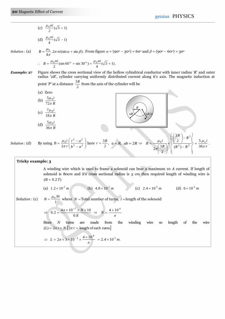
Example: 27 Figure shows the cress sectional view of the hollow cylindrical conductor with inner radius 'R' and outer radius '2R', cylinder carrying uniformly distributed current along it's axis. The magnetic induction at
point 'P' at a distance 2
3Rfrom the axis of the cylinder will be
(a) Zero
(b) R
i
72
5 0
(c) R
i
18
7 0
(d) R
i
36
5 0
Solution : (d) By using
22
220
2 ab
ar
r
iB
here ,
2
3Rr ,Ra Rab 2
22
2
0
)(
2
3
2
32
RR
RR
R
iB
r
io
36
.5 .
A winding wire which is used to frame a solenoid can bear a maximum 10 A current. If length of
solenoid is 80cm and it's cross sectional radius is 3 cm then required length of winding wire is
)2.0( TB
(a) m2102.1 (b) m2108.4 (c) m3104.2 (d) m3106
Solution : (c) l
NiB 0 where N Total number of turns, l length of the solenoid
8.0
101042.0
7
N
4104 N
Since N turns are made from the winding wire so length of the wire
NrL 2)( turnseachoflength2 r
4
2 1041032
L .104.2 3 m
2R
R
3R/2
Tricky example: 3
Magnetic Effect of Current 21 21genius PHYSICS
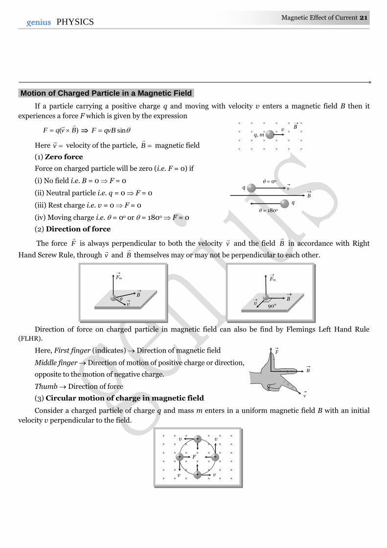
Motion of Charged Particle in a Magnetic Field.
If a particle carrying a positive charge q and moving with velocity v enters a magnetic field B then it
experiences a force F which is given by the expression
)( BvqF
sinqvBF
Here v
velocity of the particle, B
magnetic field
(1) Zero force
Force on charged particle will be zero (i.e. F = 0) if
(i) No field i.e. B = 0 F = 0
(ii) Neutral particle i.e. q = 0 F = 0
(iii) Rest charge i.e. v = 0 F = 0
(iv) Moving charge i.e. = 0o or = 180o F = 0
(2) Direction of force
The force F
is always perpendicular to both the velocity v
and the field B
in accordance with Right
Hand Screw Rule, through v
and B
themselves may or may not be perpendicular to each other.
Direction of force on charged particle in magnetic field can also be find by Flemings Left Hand Rule
(FLHR).
Here, First finger (indicates) Direction of magnetic field
Middle finger Direction of motion of positive charge or direction,
opposite to the motion of negative charge.
Thumb Direction of force
(3) Circular motion of charge in magnetic field
Consider a charged particle of charge q and mass m enters in a uniform magnetic field B with an initial
velocity v perpendicular to the field.
F
B
v
v q = 0o
= 180o
q
B
× × × × × ×
× × × × × × ×
× × × × × × ×
× × × × × × ×
× × × × × × ×
× × × × × × ×
v v
v v
F
+
+ +
+
q, m v B
v
B
Fm
90° v
B
Fm
22 Magnetic Effect of Current genius PHYSICS
= 90o, hence from F = qvB sin particle will experience a maximum magnetic force Fmax = qvB which
act's in a direction perpendicular to the motion of charged particle. (By Flemings left hand rule).
(i) Radius of the path : In this case path of charged particle is circular and magnetic force provides the
necessary centripetal force i.e. r
mvqvB
2
radius of path qB
mvr
If p = momentum of charged particle and K = kinetic energy of charged particle (gained by charged
particle after accelerating through potential difference V) then mqVmKmvp 22
So q
mV
BqB
2mK
qB
p
qB
mvr
21
Kpvr i.e. with increase in speed or kinetic energy, the radius of the orbit increases.
Note : Less radius (r) means more curvature (c) i.e. r
c1
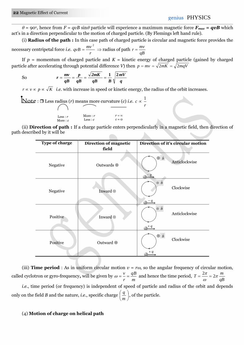
(ii) Direction of path : If a charge particle enters perpendicularly in a magnetic field, then direction of path described by it will be
Type of charge Direction of magnetic
field
Direction of it’s circular motion
Negative Outwards
Anticlockwise
Negative Inward
Clockwise
Positive Inward
Anticlockwise
Positive Outward
Clockwise
(iii) Time period : As in uniform circular motion v = r, so the angular frequency of circular motion,
called cyclotron or gyro-frequency, will be given by m
qB
r
v and hence the time period,
qB
mT
2
2
i.e., time period (or frequency) is independent of speed of particle and radius of the orbit and depends
only on the field B and the nature, i.e., specific charge
m
q, of the particle.
(4) Motion of charge on helical path
Less : r More : c
More : r Less : c
r = c = 0
B
– q
B
– q
B
+ q
B
+ q
Magnetic Effect of Current 23 23genius PHYSICS
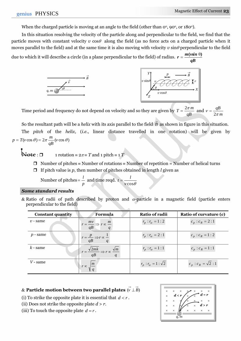
When the charged particle is moving at an angle to the field (other than 0o, 90o, or 180o).
In this situation resolving the velocity of the particle along and perpendicular to the field, we find that the
particle moves with constant velocity v cos along the field (as no force acts on a charged particle when it
moves parallel to the field) and at the same time it is also moving with velocity v sin perpendicular to the field
due to which it will describe a circle (in a plane perpendicular to the field) of radius. qB
vsinmr
)( θ
Time period and frequency do not depend on velocity and so they are given by qB
mT
2 and
m
qB
2
So the resultant path will be a helix with its axis parallel to the field B
as shown in figure in this situation.
The pitch of the helix, (i.e., linear distance travelled in one rotation) will be given by
)cos(2)cos( vqB
mvTp
Note : 1 rotation 2 T and 1 pitch 1 T
Number of pitches Number of rotations Number of repetition = Number of helical turns
If pitch value is p, then number of pitches obtained in length l given as
Number of pitchesp
l and time reqd.
cosv
lt
Some standard results
Ratio of radii of path described by proton and -particle in a magnetic field (particle enters perpendicular to the field)
Constant quantity Formula Ratio of radii Ratio of curvature (c)
v - same
qB
mvr
q
mr
2:1: rrp 1:2: Rp cc
p - same
qr
qB
pr
1
1:2: rrp 2:1: Rp cc
k - same
q
mr
qB
mkr
2
1:1: rrp 1:1: Rp cc
V - same
q
mr
2:1: rrp 1:2: Rp cc
Particle motion between two parallel plates )( Bv
(i) To strike the opposite plate it is essential that rd .
(ii) Does not strike the opposite plate d > r.
(iii) To touch the opposite plate rd .
d < r d = r
d > r
q, m
q, m
v
B
v
p
r
B Y
X
Z
v sin
v cos
24 Magnetic Effect of Current genius PHYSICS
(iv) To just not strike the opposite plate rd .
(v) To just strike the opposite plate rd .
(5) Lorentz force
When the moving charged particle is subjected simultaneously to both electric field E
and magnetic field
B
, the moving charged particle will experience electric force EqFe
and magnetic force )( BvqFm
; so the
net force on it will be )]([ BvEqF . Which is the famous ‘Lorentz-force equation’.
Depending on the directions of Ev,
and B
following situations are possible
(i) When Ev
, and B
all the three are collinear : In this situation as the particle is moving parallel or
antiparallel to the field, the magnetic force on it will be zero and only electric force will act and so m
Eq
m
Fa
The particle will pass through the field following a straight line path (parallel field) with change in its
speed. So in this situation speed, velocity, momentum kinetic energy all will change without change in direction
of motion as shown
(ii) When E is parallel to B and both these fields are perpendicular to v then : eF is
perpendicular to mF and they cannot cancel each other. The path of charged particle is curved in both these
fields.
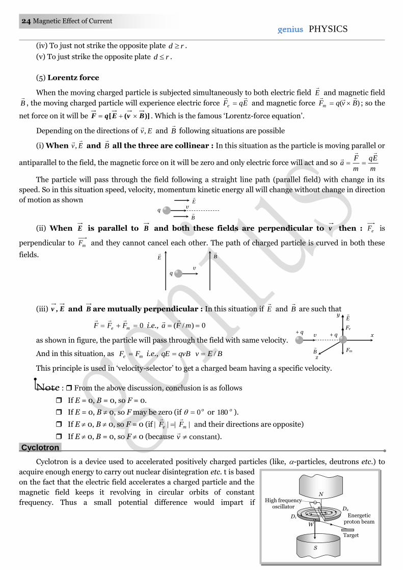
(iii) E,v and B are mutually perpendicular : In this situation if E
and B
are such that
0 me FFF
i.e., 0)/( mFa
as shown in figure, the particle will pass through the field with same velocity.
And in this situation, as me FF i.e., qvBqE BEv /
This principle is used in ‘velocity-selector’ to get a charged beam having a specific velocity.
Note : From the above discussion, conclusion is as follows
If E = 0, B = 0, so F = 0.
If E = 0, B 0, so F may be zero (if o0 or o180 ).
If E 0, B 0, so F = 0 (if |||| me FF
and their directions are opposite)
If E 0, B = 0, so F 0 (because constantv
).
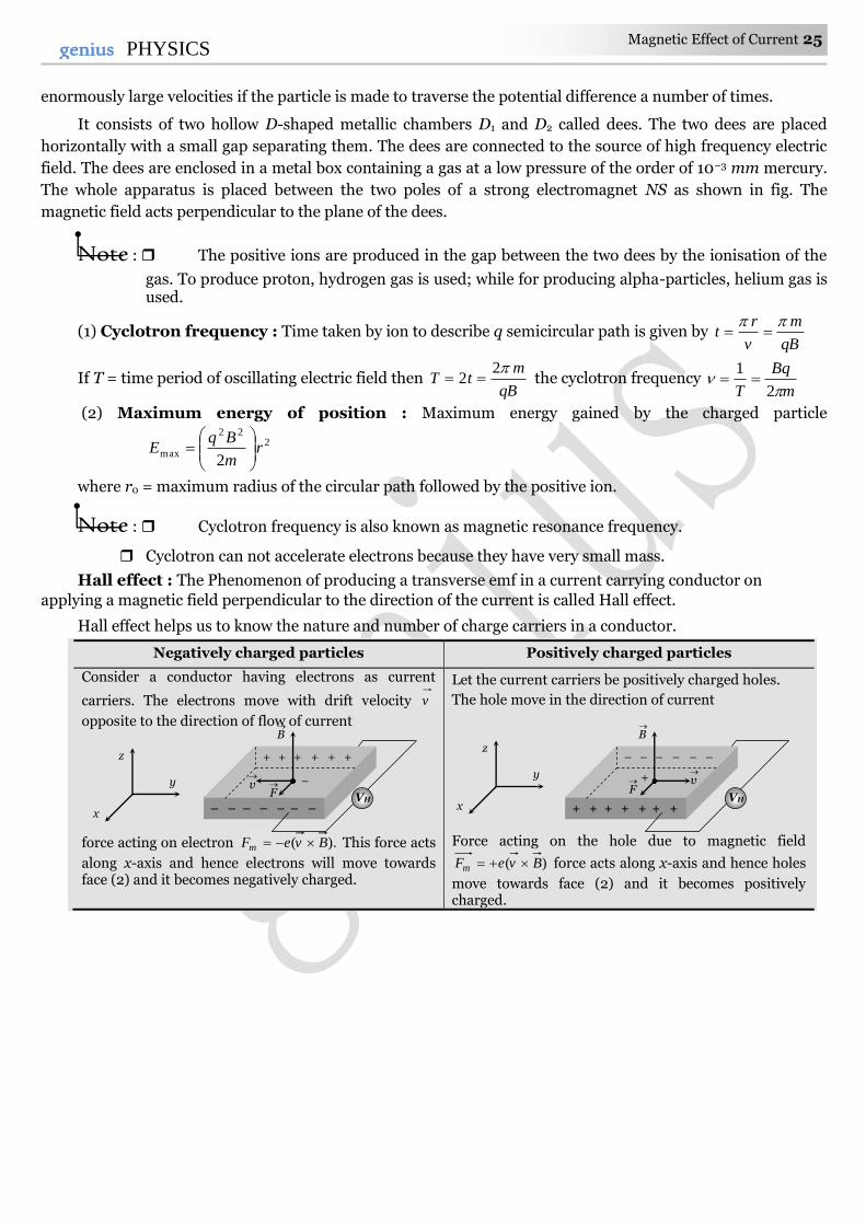
Cyclotron.
Cyclotron is a device used to accelerated positively charged particles (like, -particles, deutrons etc.) to
acquire enough energy to carry out nuclear disintegration etc. t is based
on the fact that the electric field accelerates a charged particle and the
magnetic field keeps it revolving in circular orbits of constant
frequency. Thus a small potential difference would impart if
Target
High frequency oscillator
Energetic proton beam
W
N
D1
S
D2
E
B
v q
q
E
B
v
v
z
x
Fe
+ q
Fm
+ q
y E
B
Magnetic Effect of Current 25 25genius PHYSICS
enormously large velocities if the particle is made to traverse the potential difference a number of times.
It consists of two hollow D-shaped metallic chambers D1 and D2 called dees. The two dees are placed
horizontally with a small gap separating them. The dees are connected to the source of high frequency electric
field. The dees are enclosed in a metal box containing a gas at a low pressure of the order of 10–3 mm mercury.
The whole apparatus is placed between the two poles of a strong electromagnet NS as shown in fig. The
magnetic field acts perpendicular to the plane of the dees.
Note : The positive ions are produced in the gap between the two dees by the ionisation of the
gas. To produce proton, hydrogen gas is used; while for producing alpha-particles, helium gas is used.
(1) Cyclotron frequency : Time taken by ion to describe q semicircular path is given by qB
m
v
rt
If T = time period of oscillating electric field then qB
mtT
22 the cyclotron frequency
m
Bq
T
2
1
(2) Maximum energy of position : Maximum energy gained by the charged particle
222
max2
rm
BqE
where r0 = maximum radius of the circular path followed by the positive ion.
Note : Cyclotron frequency is also known as magnetic resonance frequency.
Cyclotron can not accelerate electrons because they have very small mass.
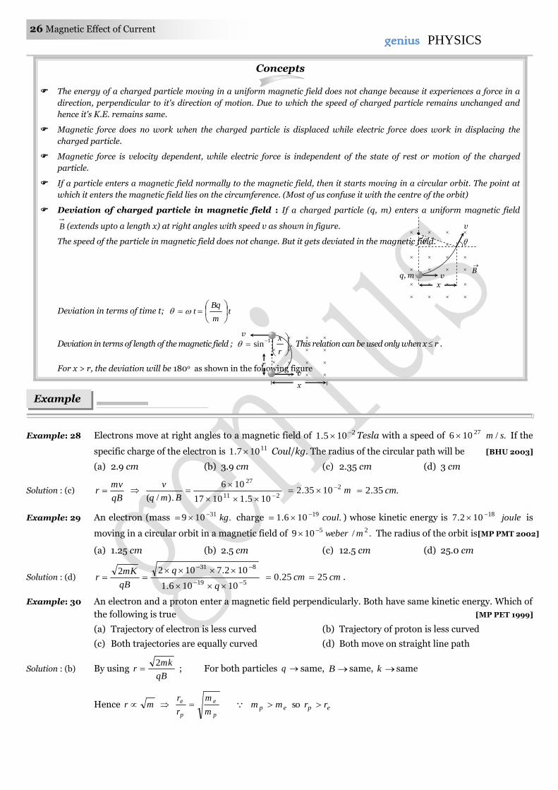
Hall effect : The Phenomenon of producing a transverse emf in a current carrying conductor on
applying a magnetic field perpendicular to the direction of the current is called Hall effect.
Hall effect helps us to know the nature and number of charge carriers in a conductor.
Negatively charged particles Positively charged particles
Consider a conductor having electrons as current
carriers. The electrons move with drift velocity v
opposite to the direction of flow of current
force acting on electron ).( BveFm This force acts
along x-axis and hence electrons will move towards face (2) and it becomes negatively charged.
Let the current carriers be positively charged holes.
The hole move in the direction of current
Force acting on the hole due to magnetic field
)( BveFm force acts along x-axis and hence holes
move towards face (2) and it becomes positively charged.
+ + + + + +
–
– – – – – – –
v
F
B
VH
x
y
z – – – – – –
+
+ + + + + + +
v
F
B
VH x
y
z
26 Magnetic Effect of Current genius PHYSICS
Concepts
The energy of a charged particle moving in a uniform magnetic field does not change because it experiences a force in a
direction, perpendicular to it's direction of motion. Due to which the speed of charged particle remains unchanged and
hence it's K.E. remains same.
Magnetic force does no work when the charged particle is displaced while electric force does work in displacing the
charged particle.
Magnetic force is velocity dependent, while electric force is independent of the state of rest or motion of the charged
particle.
If a particle enters a magnetic field normally to the magnetic field, then it starts moving in a circular orbit. The point at
which it enters the magnetic field lies on the circumference. (Most of us confuse it with the centre of the orbit)
Deviation of charged particle in magnetic field : If a charged particle (q, m) enters a uniform magnetic field
B (extends upto a length x) at right angles with speed v as shown in figure.
The speed of the particle in magnetic field does not change. But it gets deviated in the magnetic field.
Deviation in terms of time t; tm
Bqt
Deviation in terms of length of the magnetic field ;
r
x1sin . This relation can be used only when x r .
For x > r, the deviation will be 180o as shown in the following figure
Example: 28 Electrons move at right angles to a magnetic field of 2105.1 Tesla with a speed of ./106 27 sm If the
specific charge of the electron is 11107.1 Coul/kg. The radius of the circular path will be [BHU 2003]
(a) 2.9 cm (b) 3.9 cm (c) 2.35 cm (d) 3 cm
Solution : (c) qB
mvr
211
27
105.11017
106
.)/(
Bmq
v m21035.2 .35.2 cm
Example: 29 An electron (mass .109 31 kg charge .106.1 19 coul ) whose kinetic energy is joule18102.7 is
moving in a circular orbit in a magnetic field of ./109 25 mweber The radius of the orbit is[MP PMT 2002]
(a) 1.25 cm (b) 2.5 cm (c) 12.5 cm (d) 25.0 cm
Solution : (d) 519
831
10106.1
102.71022
q
q
qB
mKr cm25.0 cm25 .
Example: 30 An electron and a proton enter a magnetic field perpendicularly. Both have same kinetic energy. Which of
the following is true [MP PET 1999]
(a) Trajectory of electron is less curved (b) Trajectory of proton is less curved
(c) Both trajectories are equally curved (d) Both move on straight line path
Solution : (b) By using qB
mkr
2 ; For both particles q same, B same, k same
Hence mr p
e
p
e
m
m
r
r epep rrmm so
Examples
B
q, m
v
v
x
v
v
r
x
Magnetic Effect of Current 27 27genius PHYSICS
Since radius of the path of proton is more, hence it's trajectory is less curved.
Example: 31 A proton and an particles enters in a uniform magnetic field with same velocity, then ratio of the radii
of path describe by them
(a) 2:1 (b) 1:1 (c) 1:2 (d) None of these
Solution : (b) By using qB
mvr ; v same, B same
2
mr
p
pp
q
q
m
m
r
r
2
12
4
p
p
p
p
q
q
m
m
Example: 32 A proton of mass m and charge e is moving in a circular orbit of a magnetic field with energy 1MeV.
What should be the energy of -particle (mass = 4 m and charge = +2e), so that it can revolve in the path
of same radius [BHU 1997]
(a) 1 MeV (b) 4 MeV (c) 2 MeV (d) 0.5 MeV
Solution : (a) By using qB
mKr
2 ; r same, B same
m
qK
2
Hence
m
m
q
q
K
K p
pp
2
14
22
p
p
p
p
m
m
q
q
.1meVKK p
Example: 33 A proton and an particle enter a uniform magnetic field perpendicularly with the same speed. If
proton takes sec25 to make 5 revolutions, then the periodic time for the particle would be [MP PET 1993]
(a) sec50 (b) sec25 (c) sec10 (d) sec5
Solution : (c) Time period of proton sec55
25pT
By using qB
mT
2
q
q
m
m
T
T p
pp
p
p
p
p
q
q
m
m
2
4 .sec102 pTT
Example: 34 A particle with 10–11 coulomb of charge and 10–7 kg mass is moving with a velocity of 108 m/s along the y-
axis. A uniform static magnetic field B = 0.5 Tesla is acting along the x-direction. The force on the particle
is
[MP PMT 1997]
(a) 5 10–11 N along i (b) 5 103 N along k (c) 5 10–11 N along j (d) 5 10–4 N along k
Solution : (d) By using )( BvqF ; where jv ˆ10 and iB ˆ5.0
)ˆˆ(105)ˆ5.0ˆ10(10 4811 ijijF )ˆ(105 4 k i.e., 4105 N along .k
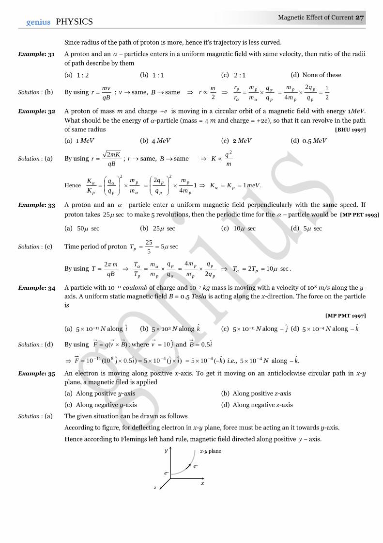
Example: 35 An electron is moving along positive x-axis. To get it moving on an anticlockwise circular path in x-y
plane, a magnetic filed is applied [MP PMT 1999]
(a) Along positive y-axis (b) Along positive z-axis
(c) Along negative y-axis (d) Along negative z-axis
Solution : (a) The given situation can be drawn as follows
According to figure, for deflecting electron in x-y plane, force must be acting an it towards y-axis.
Hence according to Flemings left hand rule, magnetic field directed along positive y axis.
y
x z
e–
e–
x-y plane
28 Magnetic Effect of Current genius PHYSICS
Example: 36 A particle of charge 181016 coulomb moving with velocity 10 m/s along the x-axis enters a region
where a magnetic field of induction B is along the y-axis, and an electric field of magnitude 104 V/m is
along the negative z-axis. If the charged particle continuous moving along the x-axis, the magnitude of B
is [AIEEE 2003]
(a) 23 /10 mWb (b) 23 /10 mWb (c) 25 /10 mWb (d) 216 /10 mWb
Solution : (b) Particles is moving undeflected in the presence of both electric field as well as magnetic field so it's speed
B
Ev
v
EB ./10
10
10 234
mWb
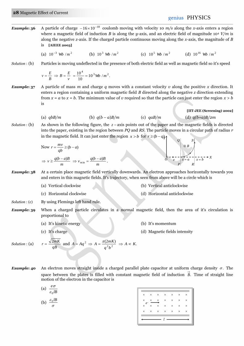
Example: 37 A particle of mass m and charge q moves with a constant velocity v along the positive x direction. It
enters a region containing a uniform magnetic field B directed along the negative z direction extending
from x = a to x = b. The minimum value of v required so that the particle can just enter the region x > b
is
[IIT-JEE (Screening) 2002]
(a) qbB/m (b) q(b – a)B/m (c) qaB/m (d) q(b+a)B/2m
Solution : (b) As shown in the following figure, the z axis points out of the paper and the magnetic fields is directed
into the paper, existing in the region between PQ and RS. The particle moves in a circular path of radius r
in the magnetic field. It can just enter the region bx for )( qbr
Now )( abqb
mvr
m
Babqv
)(
m
Babqv
)(min
.
Example: 38 At a certain place magnetic field vertically downwards. An electron approaches horizontally towards you
and enters in this magnetic fields. It's trajectory, when seen from above will be a circle which is
(a) Vertical clockwise (b) Vertical anticlockwise
(c) Horizontal clockwise (d) Horizontal anticlockwise
Solution : (c) By using Flemings left hand rule.
Example: 39 When a charged particle circulates in a normal magnetic field, then the area of it's circulation is
proportional to
(a) It's kinetic energy (b) It's momentum
(c) It's charge (d) Magnetic fields intensity
Solution : (a) qB
mKr
2 and 2AqA
22
)2(
bq
mKA
.KA
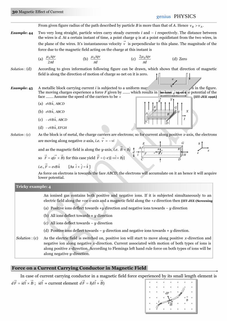
Example: 40 An electron moves straight inside a charged parallel plate capacitor at uniform charge density . The
space between the plates is filled with constant magnetic field of induction .B Time of straight line motion of the electron in the capacitor is
(a) lB
e
0
(b)
lB0
Q Y
S
O v x = a x = b
R
X
B
P
l
e–
Magnetic Effect of Current 29 29genius PHYSICS
(c) B
e
0
(d)
e
B0
Solution : (b) The net force acting on the electron is zero because it moves with constant velocity, due to it's motion on
straight line.
0 menet FFF |||| me FF evBEe BB
Eve
0
o
E
The time of motion inside the capacitor
lB
v
lt 0 .
Example: 41 A proton of mass 271067.1 kg and charge 19106.1 C is projected with a speed of sm /102 6 at an
angle of 600 to the X-axis. If a uniform magnetic field of 0.104 Tesla is applied along Y-axis, the path of
proton is [IIT-JEE 1995]
(a) A circle of radius = 0.2 m and time period 710 s
(b) A circle of radius = 0.1 m and time period 7102 s
(c) A helix of radius = 0.1 m and time period 7102 s
(d) A helix of radius = 0.2 m and time period 7104 s
Solution : (b) By using qB
mvr
sin mr 1.0
104.0106.1
30sin1021567.119
627
and it's time period qB
mT
2
104.0106.1
101.9219
31
.sec102 7
Example: 42 A charge particle, having charge q accelerated through a potential difference V enter a perpendicular
magnetic field in which it experiences a force F. If V is increased to 5V, the particle will experience a force
(a) F (b) 5F (c) 5
F (d) F5
Solution : (d) qVmv 2
2
1
m
qVv
2 . Also qvBF
m
qVqBF
2 hence VF which gives .5' FF
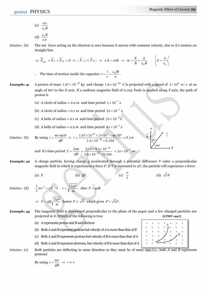
Example: 43 The magnetic field is downward perpendicular to the plane of the paper and a few charged particles are
projected in it. Which of the following is true [CPMT 1997]
(a) A represents proton and B and electron
(b) Both A and B represent protons but velocity of A is more than that of B
(c) Both A and B represents protons but velocity of B is more than that of A
(d) Both A and B represent electrons, but velocity of B is more than that of A
Solution : (c) Both particles are deflecting in same direction so they must be of same sign.(i.e., both A and B represents
protons)
By using qB
mvr vr
X
Y
v
B
30o
60o
A
B
30 Magnetic Effect of Current genius PHYSICS
From given figure radius of the path described by particle B is more than that of A. Hence .AB vv
Example: 44 Two very long straight, particle wires carry steady currents i and – i respectively. The distance between
the wires is d. At a certain instant of time, a point charge q is at a point equidistant from the two wires, in
the plane of the wires. It's instantaneous velocity v is perpendicular to this plane. The magnitude of the
force due to the magnetic field acting on the charge at this instant is [IIT-JEE 1998]
(a) d
iqv
2
0 (b) d
iqv
0 (c) d
iqv
02 (d) Zero
Solution : (d) According to gives information following figure can be drawn, which shows that direction of magnetic
field is along the direction of motion of charge so net on it is zero.
Example: 45 A metallic block carrying current i is subjected to a uniform magnetic induction B as shown in the figure. The moving charges experience a force F given by ……. which results in the lowering of the potential of the face ……. Assume the speed of the carriers to be v [IIT-JEE 1996]
(a) ABCDkeVB ,ˆ
(b) ABCDkeVB ,ˆ
(c) ABCDkeVB ,ˆ
(d) EFGHkeVB ,ˆ
Solution : (c) As the block is of metal, the charge carriers are electrons; so for current along positive x-axis, the electrons
are moving along negative x-axis, i.e. viv
and as the magnetic field is along the y-axis, i.e. jBB ˆ
so )( BvqF for this case yield ]ˆˆ)[( jBiveF
i.e., kevBF ˆ [As kji ˆˆˆ ]
As force on electrons is towards the face ABCD, the electrons will accumulate on it an hence it will acquire lower potential.
An ionised gas contains both positive and negative ions. If it is subjected simultaneously to an
electric field along the +ve x-axis and a magnetic field along the +z direction then [IIT-JEE (Screening) 2000]
(a) Positive ions deflect towards +y direction and negative ions towards – y direction
(b) All ions deflect towards + y direction
(c) All ions deflect towards – y direction
(d) Positive ions deflect towards – y direction and negative ions towards + y direction.
Solution : (c) As the electric field is switched on, positive ion will start to move along positive x-direction and
negative ion along negative x-direction. Current associated with motion of both types of ions is
along positive x-direction. According to Flemings left hand rule force on both types of ions will be
along negative y-direction.
Force on a Current Carrying Conductor in Magnetic Field.
In case of current carrying conductor in a magnetic field force experienced by its small length element is
BlidFd ; lid = current element )( BldlFd
× × × × × ×
× × × × × × ×
× × × × × ×
× × × × × × ×
× × × × × × ×
× × × × × × ×
dl i
dF
B
v
d
d/2 d/2
q
Tricky example: 4
E G
A
D
v
B
F
e–
C
F i d
B
H
y
x z
B Y
G
X
I
B A
E
H F
D C
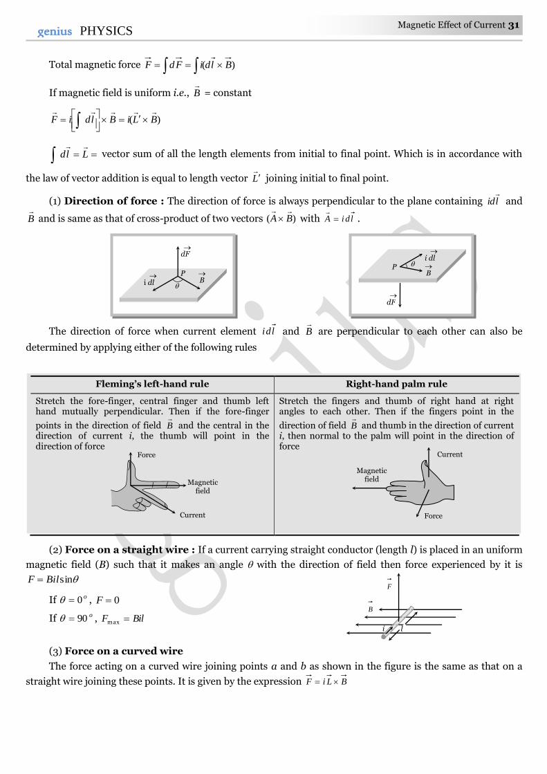
Magnetic Effect of Current 31 31genius PHYSICS
Total magnetic force )( BldiFdF
If magnetic field is uniform i.e., B
= constant
)( BLiBldiF
Lld
vector sum of all the length elements from initial to final point. Which is in accordance with
the law of vector addition is equal to length vector L joining initial to final point.
(1) Direction of force : The direction of force is always perpendicular to the plane containing lid
and
B
and is same as that of cross-product of two vectors )( BA
with ldiA
.
The direction of force when current element ldi and B
are perpendicular to each other can also be
determined by applying either of the following rules
Fleming’s left-hand rule Right-hand palm rule
Stretch the fore-finger, central finger and thumb left hand mutually perpendicular. Then if the fore-finger
points in the direction of field B
and the central in the direction of current i, the thumb will point in the direction of force
Stretch the fingers and thumb of right hand at right angles to each other. Then if the fingers point in the
direction of field B
and thumb in the direction of current i, then normal to the palm will point in the direction of force
(2) Force on a straight wire : If a current carrying straight conductor (length l) is placed in an uniform
magnetic field (B) such that it makes an angle with the direction of field then force experienced by it is
sinBilF
If o0 , 0F
If o90 , BilF max
(3) Force on a curved wire
The force acting on a curved wire joining points a and b as shown in the figure is the same as that on a
straight wire joining these points. It is given by the expression BLiF
B
dF
i dl P
B
dF
i dl
P
Force
Magnetic field
Current
i l
B
F
Current
Force
Magnetic field
32 Magnetic Effect of Current genius PHYSICS
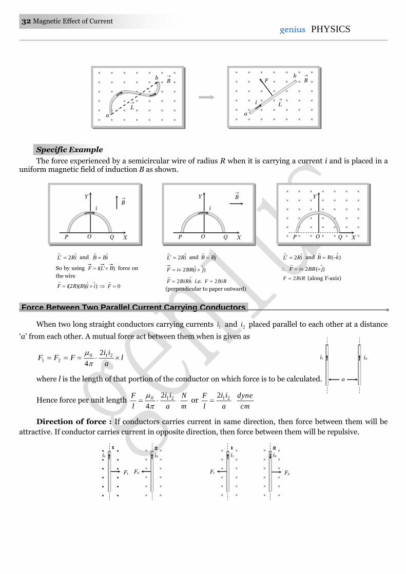
Specific Example
The force experienced by a semicircular wire of radius R when it is carrying a current i and is placed in a uniform magnetic field of induction B as shown.
Force Between Two Parallel Current Carrying Conductors.
When two long straight conductors carrying currents 1i and 2i placed parallel to each other at a distance
‘a’ from each other. A mutual force act between them when is given as
la
iiFFF 210
21
2
4
where l is the length of that portion of the conductor on which force is to be calculated.
Hence force per unit length a
ii
l
F 210 2
4
m
N or
a
ii
l
F 212
cm
dyne
Direction of force : If conductors carries current in same direction, then force between them will be
attractive. If conductor carries current in opposite direction, then force between them will be repulsive.
i2 i1
a
Y
O P Q X
B
i
× × × × × × ×
× × × × × × ×
× × × × × × ×
× × × × × × ×
× × × × × × ×
× × × × × × ×
Y
O P Q X
iRL ˆ2
and jBB ˆ
)ˆ(2 jiBRiF
kBiRF ˆ2
i.e. BiRF 2
(perpendicular to paper outward)
iRL ˆ2
and )ˆ( kBB
)ˆ(2 jBRiF
BiRF 2 (along Y-axis)
iRL ˆ2
and iBB ˆ
So by using )'( BLiF force on
the wire
)ˆˆ)()(2( iiBRiF
0F
Y
O P Q X
B
i
× ×
× ×
× ×
× ×
× ×
× ×
i2 i1
2 1
F2 F1
× ×
× ×
× ×
× ×
× ×
× ×
i2
2
F2
× ×
× ×
× ×
× ×
× ×
× ×
i1
1
F1
× × × × × × ×
× × × × × × ×
× × × × × × ×
× × × × × × ×
× × × × × × ×
× × × × × × ×
L
B
a
b × × × × × × ×
× × × × × × ×
× × × × × × ×
× × × × × × ×
× × × × × × ×
× × × × × × ×
B
L
i
F
a
b
Magnetic Effect of Current 33 33genius PHYSICS
Note : If a = 1m and in free space mNl
F/102 7 then Ampii 121 in each identical wire.
By this concept S.I. unit of Ampere is defined. This is known as Ampere’s law.
Force Between Two Moving Charges.
If two charges q1 and q2 are moving with velocities v1 and v2 respectively and at any instant the distance
between them is r, then
Magnetic force between them is 2
21210 .4 r
vvqqFm
..... (i)
and Electric force between them is 2
21
0
.4
1
r
qqFe
..... (ii)
From equation (i) and (ii) 200 v
F
F
e
m but 200
1
c ; where c is the velocity light in vacuum. So
2
c
v
F
F
e
m
If v << c then Fm << Fe
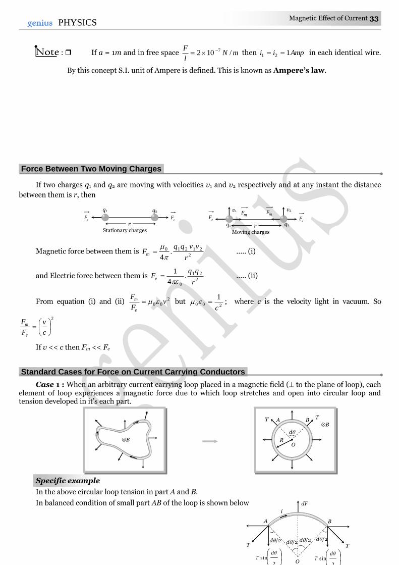
Standard Cases for Force on Current Carrying Conductors.
Case 1 : When an arbitrary current carrying loop placed in a magnetic field ( to the plane of loop), each element of loop experiences a magnetic force due to which loop stretches and open into circular loop and tension developed in it’s each part.
Specific example
In the above circular loop tension in part A and B.
In balanced condition of small part AB of the loop is shown below
B
B
O R
d
A T T B
T
A B
dF
d/2
2sin
dθT
2sin
dθT
d/2 d/2 d/2 T
i
O
r
q1 q2
eF
eF
Stationary charges r q1 q2
eF e
F
Moving charges
v1 v2 mF mF
34 Magnetic Effect of Current genius PHYSICS
dliBdFd
T 2
sin2
BiRdd
T 2
sin2
If d is small so, 22
sin dd
BiRdd
T 2
.2
BiRT , if LR 2 so 2
BiLT
Note : If no magnetic field is present, the loop will still open into a circle as in it’s adjacent parts
current will be in opposite direction and opposite currents repel each other.
Case 2 : Equilibrium of a current carrying conductor : When a finite length current carrying wire
is kept parallel to another infinite length current carrying wire, it can suspend freely in air as shown below
In both the situations for equilibrium of XY it's downward weight = upward magnetic force i.e.
.lh
ii.
π
μmg 210 2
4
Note : In the first case if wire XY is slightly displaced from its equilibrium position, it executes
SHM and it’s time period is given by g
hT 2 .
If direction of current in movable wire is reversed then it’s instantaneous acceleration produced is
2g .
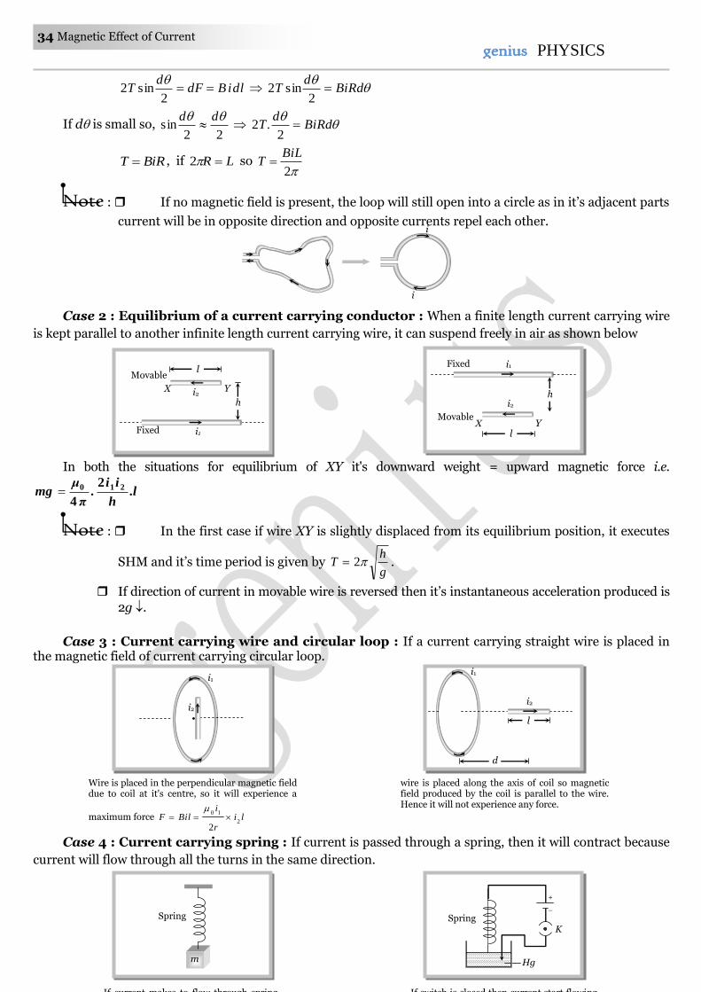
Case 3 : Current carrying wire and circular loop : If a current carrying straight wire is placed in the magnetic field of current carrying circular loop.
Case 4 : Current carrying spring : If current is passed through a spring, then it will contract because
current will flow through all the turns in the same direction.
i
i
Spring
m
If current makes to flow through spring,
Spring
Hg
– +
K
If switch is closed then current start flowing,
i1
i2
Wire is placed in the perpendicular magnetic field due to coil at it's centre, so it will experience a
maximum force lir
iBilF
2
10
2
wire is placed along the axis of coil so magnetic field produced by the coil is parallel to the wire. Hence it will not experience any force.
i2
i1
d
l
Fixed
h
Y X
i1
i2
l Movable
Fixed
Y X
i2
i1
l
Movable
h
Magnetic Effect of Current 35 35genius PHYSICS
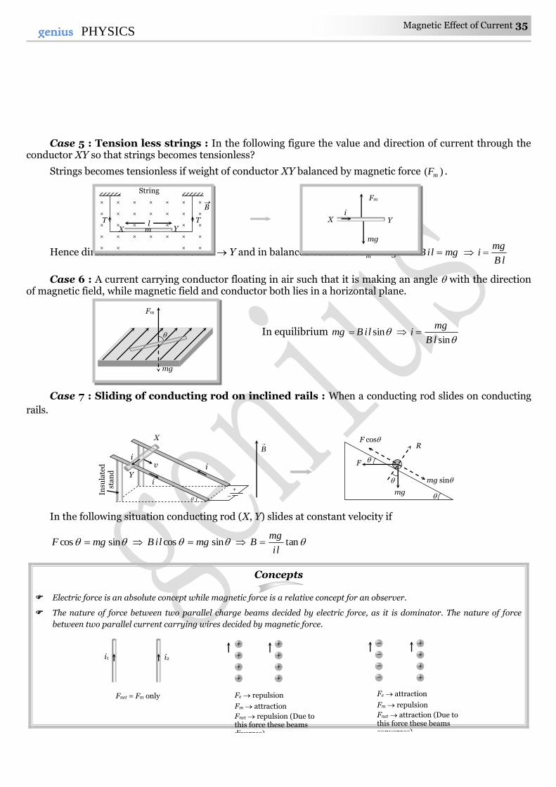
Case 5 : Tension less strings : In the following figure the value and direction of current through the conductor XY so that strings becomes tensionless?
Strings becomes tensionless if weight of conductor XY balanced by magnetic force )( mF .
Hence direction of current is from X Y and in balanced condition mgFm mgliB lB
mgi
Case 6 : A current carrying conductor floating in air such that it is making an angle with the direction of magnetic field, while magnetic field and conductor both lies in a horizontal plane.
In equilibrium sinliBmg sinlB
mgi
Case 7 : Sliding of conducting rod on inclined rails : When a conducting rod slides on conducting
rails.
In the following situation conducting rod (X, Y) slides at constant velocity if
sincos mgF sincos mgliB tanli
mgB
Concepts
Electric force is an absolute concept while magnetic force is a relative concept for an observer.
The nature of force between two parallel charge beams decided by electric force, as it is dominator. The nature of force
between two parallel current carrying wires decided by magnetic force.
mg
Fm
× × × × × × ×
× × × × × × ×
× × × × × × ×
× × × × × × ×
× × × ×
T T
B
X Y
String
l m
i X Y
mg
Fm
R
mg
mg sin
F cos
F
B
X
v
Y
Insu
late
d
sta
nd
i
i
i +
–
+
+
+
+
+
+
+
+
Fe repulsion
Fm attraction
Fnet repulsion (Due to this force these beams diverges)
–
–
–
–
+
+
+
+
Fe attraction
Fm repulsion
Fnet attraction (Due to this force these beams converges)
i2 i1
Fnet = Fm only
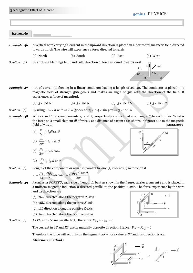
36 Magnetic Effect of Current genius PHYSICS
Example: 46 A vertical wire carrying a current in the upward direction is placed in a horizontal magnetic field directed
towards north. The wire will experience a force directed towards
(a) North (b) South (c) East (d) West
Solution : (d) By applying Flemings left hand rule, direction of force is found towards west.
Example: 47 3 A of current is flowing in a linear conductor having a length of 40 cm. The conductor is placed in a
magnetic field of strength 500 gauss and makes an angle of 30o with the direction of the field. It
experiences a force of magnitude [MP PET 1993]
(a) 3 104 N (b) 3 102 N (c) 3 10– 2 N (d) 3 10–4 N
Solution : (c) By using sinBilF F = (500 10–4) 0.4 sin 30o 3 10–2 N.
Example: 48 Wires 1 and 2 carrying currents 1t and 2t respectively are inclined at an angle to each other. What is
the force on a small element dl of wire 2 at a distance of r from 1 (as shown in figure) due to the magnetic field of wire 1 [AIEEE 2002]
(a)
tan,
221
0 dliir
(b)
sin,
221
0 dliir
(c)
cos,
221
0 dliir
(d)
sin,
421
0 dliir
Solution : (c) Length of the component dl which is parallel to wire (1) is dl cos , so force on it
r
dliidl
r
iiF
2
cos)cos(
2
4
210210 .
Example: 49 A conductor PQRSTU, each side of length L, bent as shown in the figure, carries a current i and is placed in
a uniform magnetic induction B directed parallel to the positive Y-axis. The force experience by the wire
and its direction are
(a) 2iBL directed along the negative Z-axis
(b) 5iBL directed along the positive Z-axis
(c) iBL direction along the positive Z-axis
(d) 2iBL directed along the positive Z-axis
Solution : (c) As PQ and UT are parallel to Q, therefore 0 UTPQ FF
The current in TS and RQ are in mutually opposite direction. Hence, 0 RQTS FF
Therefore the force will act only on the segment SR whose value is Bil and it’s direction is +z.
Alternate method :
Examples
BH i
N W
E S
F
ZR
Q P
Y
UT
B
i
S
X
B
ZR
Q P
Y
UT
i
S
X
P
U
F
i
B
i1 i2
dl
r
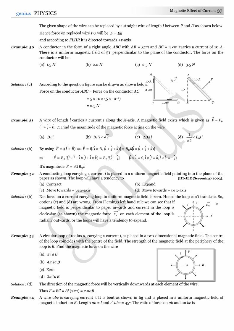
Magnetic Effect of Current 37 37genius PHYSICS
The given shape of the wire can be replaced by a straight wire of length l between P and U as shown below
Hence force on replaced wire PU will be BilF
and according to FLHR it is directed towards +z-axis
Example: 50 A conductor in the form of a right angle ABC with AB = 3cm and BC = 4 cm carries a current of 10 A.
There is a uniform magnetic field of 5T perpendicular to the plane of the conductor. The force on the
conductor will be [MP PMT 1997]
(a) 1.5 N (b) 2.0 N (c) 2.5 N (d) 3.5 N
Solution : (c) According to the question figure can be drawn as shown below.
Force on the conductor ABC = Force on the conductor AC
= 5 10 (5 10–2)
= 2.5 N
Example: 51 A wire of length l carries a current i along the X-axis. A magnetic field exists which is given as 0BB
( )ˆˆˆ kji T. Find the magnitude of the magnetic force acting on the wire
(a) ilB0 (b) 20 liB (c) liB02 (d) liB02
1
Solution : (b) By using )( BliF )]ˆˆ([)]ˆˆ(ˆ[ 00 kjiiilBkjiBiliF
]ˆˆˆˆˆ[0 kijiiiilBF ]ˆˆ[0 jkilB }ˆˆˆ,ˆˆˆ,0ˆ{ jkikjiii
It's magnitude ilBF 02
Example: 52 A conducting loop carrying a current i is placed in a uniform magnetic field pointing into the plane of the paper as shown. The loop will have a tendency to [IIT-JEE (Screening) 2003]]
(a) Contract (b) Expand
(c) Move towards + ve x-axis (d) Move towards – ve x-axis
Solution : (b) Net force on a current carrying loop in uniform magnetic field is zero. Hence the loop can't translate. So,
options (c) and (d) are wrong. From Flemings left hand rule we can see that if
magnetic field is perpendicular to paper inwards and current in the loop is
clockwise (as shown) the magnetic force mF on each element of the loop is
radially outwards, or the loops will have a tendency to expand.
Example: 53 A circular loop of radius a, carrying a current i, is placed in a two-dimensional magnetic field. The centre
of the loop coincides with the centre of the field. The strength of the magnetic field at the periphery of the
loop is B. Find the magnetic force on the wire
(a) Bai
(b) Bai4
(c) Zero
(d) Bai2
Solution : (d) The direction of the magnetic force will be vertically downwards at each element of the wire.
Thus F = Bil = Bi (2a) = 2iaB.
Example: 54 A wire abc is carrying current i. It is bent as shown in fig and is placed in a uniform magnetic field of
magnetic induction B. Length ab = l and abc = 45o. The ratio of force on ab and on bc is
i Y
B a
i Y
X
Fm
A
B C
3 cm
4 cm
10 A B
A
C
10 A F
B
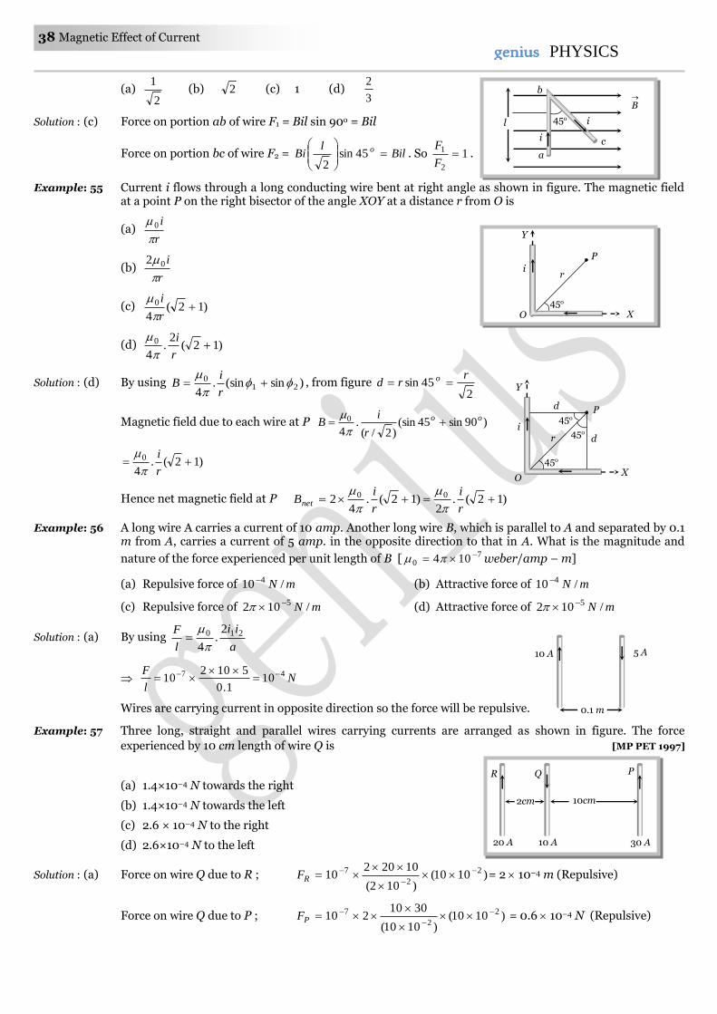
38 Magnetic Effect of Current genius PHYSICS
(a) 2
1 (b) 2 (c) 1 (d)
3
2
Solution : (c) Force on portion ab of wire F1 = Bil sin 90o = Bil
Force on portion bc of wire F2 = Bill
Bi o
45sin
2. So 1
2
1 F
F.
Example: 55 Current i flows through a long conducting wire bent at right angle as shown in figure. The magnetic field at a point P on the right bisector of the angle XOY at a distance r from O is
(a) r
i
0
(b) r
i
02
(c) )12(4
0 r
i
(d) )12(2
.4
0 r
i
Solution : (d) By using )sin(sin.4
210
r
iB , from figure
245sin
rrd o
Magnetic field due to each wire at P )90sin45(sin)2/(
.4
0 oo
r
iB
)12(.4
0 r
i
Hence net magnetic field at P )12(.2
)12(.4
2 00 r
i
r
iBnet
Example: 56 A long wire A carries a current of 10 amp. Another long wire B, which is parallel to A and separated by 0.1 m from A, carries a current of 5 amp. in the opposite direction to that in A. What is the magnitude and
nature of the force experienced per unit length of B [ 70 104 weber/amp – m] [MP PET 2000]
(a) Repulsive force of mN /10 4 (b) Attractive force of mN /10 4
(c) Repulsive force of mN /102 5 (d) Attractive force of mN /102 5
Solution : (a) By using a
ii
l
F 210 2.
4
Nl
F 47 101.0
510210
Wires are carrying current in opposite direction so the force will be repulsive.
Example: 57 Three long, straight and parallel wires carrying currents are arranged as shown in figure. The force
experienced by 10 cm length of wire Q is [MP PET 1997]
(a) 1.4×10⁻⁴ N towards the right
(b) 1.4×10⁻⁴ N towards the left
(c) 2.6 × 10⁻⁴ N to the right
(d) 2.6×10⁻⁴ N to the left
Solution : (a) Force on wire Q due to R ; )1010()102(
1020210 2
2
7
RF = 2 10–4 m (Repulsive)
Force on wire Q due to P ; )1010()1010(
3010210 2
2
7
PF = 0.6 10–4 N (Repulsive)
10 A 5 A
0.1 m
10cm 2cm
R Q
10 A 20 A 30 A
P
45o
P
X
Y
r i
O
d
i
45o
d
P 45o
45o
X
Y
r
O
l
B
45o
a
c i
i
b
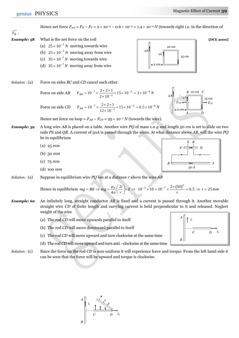
Magnetic Effect of Current 39 39genius PHYSICS
Hence net force Fnet = FR – FP = 2 10–4 – 0.6 10–4 = 1.4 10–4 N (towards right i.e. in the direction of
RF .
Example: 58 What is the net force on the coil [DCE 2000]
(a) N71025 moving towards wire
(b) N71025 moving away from wire
(c) N71035 moving towards wire
(d) N71035 moving away from wire
Solution : (a) Force on sides BC and CD cancel each other.
Force on side AB NFAB62
2
7 1031015102
12210
Force on side CD NFAB62
2
7 105.010151012
12210
Hence net force on loop = FAB – FCD = 25 10–7 N (towards the wire).
Example: 59 A long wire AB is placed on a table. Another wire PQ of mass 1.0 g and length 50 cm is set to slide on two
rails PS and QR. A current of 50A is passed through the wires. At what distance above AB, will the wire PQ
be in equilibrium
(a) 25 mm
(b) 50 mm
(c) 75 mm
(d) 100 mm
Solution : (a) Suppose in equilibrium wire PQ lies at a distance r above the wire AB
Hence in equilibrium Bilmg ilr
img
2
4
0
5.0
)50(2101010
273
r mmr 25
Example: 60 An infinitely long, straight conductor AB is fixed and a current is passed through it. Another movable
straight wire CD of finite length and carrying current is held perpendicular to it and released. Neglect
weight of the wire
(a) The rod CD will move upwards parallel to itself
(b) The rod CD will move downward parallel to itself
(c) The rod CD will move upward and turn clockwise at the same time
(d) The rod CD will move upward and turn anti –clockwise at the same time
Solution : (c) Since the force on the rod CD is non-uniform it will experience force and torque. From the left hand side it
can be seen that the force will be upward and torque is clockwise.
2A
2 cm
10 cm
15 cm
B C
A D
FCD FAB
1A
2A
2 cm
10 cm
15 cm 1A
A
50 A B
P Q
S R
A
B
i1
C D i2
A
B
i1
C D i2
40 Magnetic Effect of Current genius PHYSICS
A current carrying wire LN is bent in the from shown below. If wire carries a current of 10 A and it is placed in a magnetic field a 5T which acts perpendicular to the paper outwards then it will experience a force
(a) Zero
(b) 5 N
(c) 30 N
(d) 20 N
Solution : (b) The given wire can be replaced by a straight wire as shown below
Hence force experienced by the wire F = Bil = 5 10 0.1 = 5 N
A wire, carrying a current i, is kept in YX plane along the curve .2
sin
xAy
A magnetic
field B exists in the Z-direction find the magnitude of the magnetic force on the portion of the wire
between 0x and x
(a) Bi (b) Zero (c) 2
Bi (d) Bi2/3
Solution : (a) The given curve is a sine curve as shown below.
The given portion of the curved wire may be treated as a straight wire AB of length which
experiences a magnetic force BiFm
Current Loop As a Magnetic Dipole.
A current carrying circular coil behaves as a bar magnet whose magnetic moment is M = NiA; Where N =
Number of turns in the coil, i = Current through the coil and A = Area of the coil
Magnetic moment of a current carrying coil is a vector and it's direction is given by right hand thumb rule
Z
Y
X
i
B A
x = 0 x =
Tricky example: 6
M Magnetic
moment
Current
Tricky example: 5
4 cm
10A
L
N
4 cm
6 cm
10A
L
N
4 cm
10A
L
N
4 cm
6 cm
6 cm L
N
10 cm
S N
Magnetic Effect of Current 41 41genius PHYSICS
Specific examples
A given length constant current carrying straight wire moulded into different shaped loops. as shown
Linear Square Equilateral Circle
l = 4a l = 3a l = 2r
A = a2 2
4
3aA A = r2
16
22 il
iaM 36
3
4
32
2 ilaiM
4)(
22 il
riM max.
Note : For a given perimeter circular shape have maximum area. Hence maximum magnetic
moment.
For a any loop or coil B and M are always parallel.
Behaviour of Current loop In a Magnetic Field.
(1) Torque
Consider a rectangular current carrying coil PQRS having N turns and area A, placed in a uniform field B,
in such a way that the normal )ˆ(n to the coil makes an angle with the direction of B. the coil experiences a
torque given by = NBiA sin . Vectorially BM
(i) is zero when = 0, i.e., when the plane of the coil is perpendicular to the field.
(ii) is maximum when o90 , i.e., the plane of the coil is parallel to the field.
NBiAmax
The above expression is valid for coils of all shapes.
(2) Workdone
If coil is rotated through an angle from it's equilibrium position then required work. ).cos1( MBW
It is maximum when = 180o Wmax = 2 MB
(3) Potential energy
Is given by U = – MB cos BMU .
Note : Direction of M is found by using Right hand thumb rule according to which curl the
fingers of right hand in the direction of circulation of conventional current, then the thumb gives
the direction of M .
MB , MB ,
PQ = RS =i QR = SP = b
B
S
Q
P
R
n ^
a
i
i
l
i i
42 Magnetic Effect of Current genius PHYSICS
Instruments such as electric motor, moving coil galvanometer and tangent galvanometers etc. are
based on the fact that a current-carrying coil in a uniform magnetic field experiences a torque (or
couple).
Moving coil galvanometer.
In a moving coil galvanometer the coil is suspended between the pole pieces of a strong horse-shoe
magnet. The pole pieces are made cylinderical and a soft iron cylinderical core is placed within the coil without
touching it. This makes the field radial. In such a field the plane of the coil always remains parallel to the field.
Therefore o90 and the deflecting torque always has the maximum value.
NBiAdef ......(i)
coil deflects, a restoring torque is set up in the suspension fibre. If is the angle of twist, the restoring torque is
Crest .....(ii) where C is the torsional constant of the fibre.
When the coil is in equilibrium.
NBiA = C NBA
Ci Ki ,
Where NBA
CK is the galvanometer constant. This linear relationship between i and makes the
moving coil galvanometer useful for current measurement and detection.
Current sensitivity : The current sensitivity of a galvanometer is defined as the deflection produced in
the galvanometer per unit current flowing through it.
C
NBA
iS i
Thus in order to increase the sensitivity of a moving coil galvanometer, N, B and A should be increased
and C should be decreased.
Quartz fibres can also be used for suspension of the coil because they have large tensile strength and very
low value of k.
Voltage sensitivity (SV) : Voltage sensitivity of a galvanometer is defined as the deflection produced in the galvanometer per unit applied to it.
RC
NBA
R
S
iRVS i
V
Concepts
The field in a moving coil galvanometer radial in nature in order to have a linear relation between the current and the deflection.
A rectangular current loop is in an arbitrary orientation in an external magnetic field. No work required to rotate the loop
Spring
1
0
2 3
4 5 1 2
3 4
5
N S Moving coil
Magnet (fixed)
Moving coil Galvanometer
F=nBil F
F
Core N S
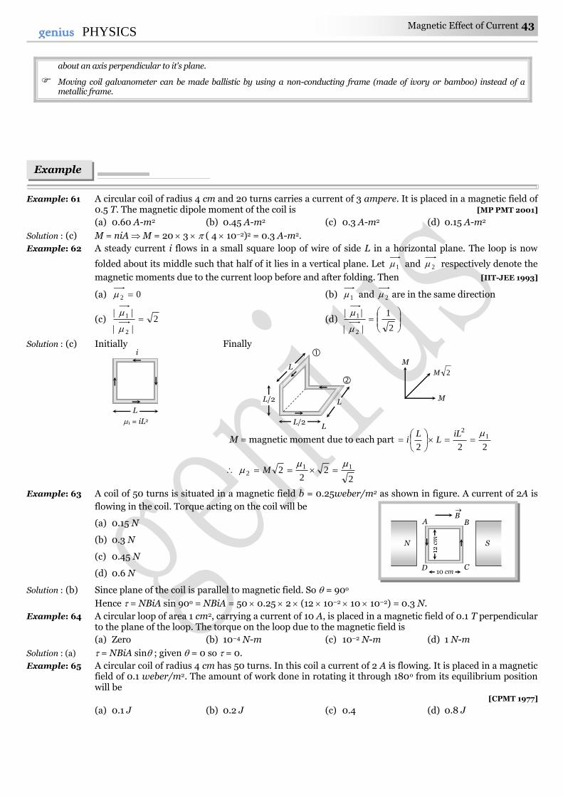
Magnetic Effect of Current 43 43genius PHYSICS
about an axis perpendicular to it's plane.
Moving coil galvanometer can be made ballistic by using a non-conducting frame (made of ivory or bamboo) instead of a metallic frame.
Example: 61 A circular coil of radius 4 cm and 20 turns carries a current of 3 ampere. It is placed in a magnetic field of 0.5 T. The magnetic dipole moment of the coil is [MP PMT 2001]
(a) 0.60 A-m2 (b) 0.45 A-m2 (c) 0.3 A-m2 (d) 0.15 A-m2
Solution : (c) M = niA M = 20 3 ( 4 10–2)2 = 0.3 A-m2.
Example: 62 A steady current i flows in a small square loop of wire of side L in a horizontal plane. The loop is now
folded about its middle such that half of it lies in a vertical plane. Let 1 and 2 respectively denote the
magnetic moments due to the current loop before and after folding. Then [IIT-JEE 1993]
(a) 02 (b) 1 and 2 are in the same direction
(c) 2||
||
2
1
(d)
2
1
||
||
2
1
Solution : (c) Initially Finally
M = magnetic moment due to each part 222
12
iLL
Li
2
22
2 112
M
Example: 63 A coil of 50 turns is situated in a magnetic field b = 0.25weber/m2 as shown in figure. A current of 2A is
flowing in the coil. Torque acting on the coil will be
(a) 0.15 N
(b) 0.3 N
(c) 0.45 N
(d) 0.6 N
Solution : (b) Since plane of the coil is parallel to magnetic field. So = 90o
Hence = NBiA sin 90o = NBiA = 50 0.25 2 (12 10–2 10 10–2) = 0.3 N.
Example: 64 A circular loop of area 1 cm2, carrying a current of 10 A, is placed in a magnetic field of 0.1 T perpendicular to the plane of the loop. The torque on the loop due to the magnetic field is
(a) Zero (b) 10–4 N-m (c) 10–2 N-m (d) 1 N-m
Solution : (a) = NBiA sin ; given = 0 so = 0.
Example: 65 A circular coil of radius 4 cm has 50 turns. In this coil a current of 2 A is flowing. It is placed in a magnetic field of 0.1 weber/m2. The amount of work done in rotating it through 180o from its equilibrium position will be
[CPMT 1977]
(a) 0.1 J (b) 0.2 J (c) 0.4 (d) 0.8 J
N S
B
A B
D C
12 c
m
10 cm
Examples
L
i
1 = iL2
L L/2
L/2
L
L
M
2M
M
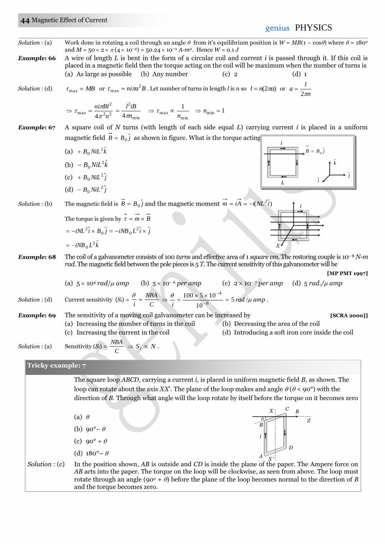
44 Magnetic Effect of Current genius PHYSICS
Solution : (a) Work done in rotating a coil through an angle from it's equilibrium position is W = MB(1 – cos) where = 180o
and M = 50 2 (4 10–2) = 50.24 10–2 A-m2. Hence W = 0.1 J
Example: 66 A wire of length L is bent in the form of a circular coil and current i is passed through it. If this coil is placed in a magnetic field then the torque acting on the coil will be maximum when the number of turns is
(a) As large as possible (b) Any number (c) 2 (d) 1
Solution : (d) MBmax or Bani 2max . Let number of turns in length l is n so )2( anl or
n
la
2
22
2
max4 n
Blni
min
2
4 n
iBl
minmax
1
n 1min n
Example: 67 A square coil of N turns (with length of each side equal L) carrying current i is placed in a uniform
magnetic field jBB ˆ0 as shown in figure. What is the torque acting on the coil
(a) kNiLB ˆ20
(b) kNiLB ˆ20
(c) jNiLB ˆ20
(d) jNiLB ˆ20
Solution : (b) The magnetic field is jBB ˆ0 and the magnetic moment )ˆ( 2 iNLiAim
The torque is given by Bm
jBiiNL ˆˆ0
2 jiLiNB ˆˆ20
kLiNB ˆ20
Example: 68 The coil of a galvanometer consists of 100 turns and effective area of 1 square cm. The restoring couple is 10– 8 N-m rad. The magnetic field between the pole pieces is 5 T. The current sensitivity of this galvanometer will be
[MP PMT 1997]
(a) 5 104 rad/ amp (b) 5 10– 6 per amp (c) 2 10– 7 per amp (d) 5 rad./ amp
Solution : (d) Current sensitivity (Si) = C
NBA
i
amprad
i
/5
10
1051008
4
.
Example: 69 The sensitivity of a moving coil galvanometer can be increased by [SCRA 2000]]
(a) Increasing the number of turns in the coil (b) Decreasing the area of the coil
(c) Increasing the current in the coil (d) Introducing a soft iron core inside the coil
Solution : (a) Sensitivity (Si) = C
NBA NS i .
The square loop ABCD, carrying a current i, is placed in uniform magnetic field B, as shown. The
loop can rotate about the axis XX'. The plane of the loop makes and angle ( < 90°) with the
direction of B. Through what angle will the loop rotate by itself before the torque on it becomes zero
(a)
(b) 90°–
(c) 90° +
(d) 180°–
Solution : (c) In the position shown, AB is outside and CD is inside the plane of the paper. The Ampere force on AB acts into the paper. The torque on the loop will be clockwise, as seen from above. The loop must
rotate through an angle (90o + ) before the plane of the loop becomes normal to the direction of B and the torque becomes zero.
Tricky example: 7
X C
D
A X
i
B
Z
B
j
k
i
jBB ˆ0
L
i
X
i

Magnetic Effect of Current 45 45genius PHYSICS