Magnetic Drive refers to the coupling between the wet … · 1.03.2011 · "Magnetic Drive" refers...
19
"Magnetic Drive" refers to the coupling between the wet end of the pump and the motor. In "direct drive" pumps, the impeller of the pump is attached to the shaft of the motor, and this design depends on the shaft seal to contain the chemical. In a magnetic drive pump, the wet end and motor are two separate contained parts, connected by only a motor bracket. At the end of the motor shaft, a drive magnet is attached, and as the drive magnet rotates around the rear housing, the impeller, which is fixed upon another magnet, spins in synchronization. It is the attraction of the drive magnet and the impeller magnet that allows the full torque of the motor to be passed onto the pump. As the shaft of the motor does not extend into the interior of the pump, there is no need for a shaft seal, and without a shaft seal, the danger of leakage commonly associated with a shaft seal is eliminated. Furthermore, the maintenance cost is reduced because no time or money is spent on maintaining the shaft seal. For a pump that eliminates the problems and costs associated with mechanical seals, the Magnetic Drive Pump has no equal. http://www.klausunion.com/mag-drive-pumps/features/mag-drive- cutaway.php#Internal_Flush_Flow Section B -- Pump Application Data B-4B Magnetic Drive Pumps INTRODUCTION Environmental concerns and recurring mechanical seal problems have created a need for sealless pumps in the chemical and petrochemical industries. In some cases, more stringent regulations by the EPA, OSHA and local agencies are mandating the use of sealless pumps. One type of sealless pump is the magnetic drive pump which uses a permanent magnetic coupling to transmit torque to the impeller without the need for a mechanical seal for packing. PRINCIPLES OF OPERATION Magnetic drive pumps use a standard electric motor to drive a set of permanent magnets that are mounted on a carrier or drive assembly located outside of the containment shell. The drive magnet assembly is mounted on a second shaft which is driven by a standard motor. The external rotating magnetic field drives the inner rotor. The coaxial synchronous torque coupling consists of two rings of permanent magnets as shown in Fig. 1. A magnetic force field is established between the north and south pole magnets in the drive and driven assemblies. This provides the no slip or synchronous capability of the torque coupling. The magnetic
Transcript of Magnetic Drive refers to the coupling between the wet … · 1.03.2011 · "Magnetic Drive" refers...

"Magnetic Drive" refers to the coupling between the wet end of the pump and the motor. In "direct drive" pumps, the impeller of the pump is attached to the shaft of the motor, and this design depends on the shaft seal to contain the chemical. In a magnetic drive pump, the wet end and motor are two separate contained parts, connected by only a motor bracket. At the end of the motor shaft, a drive magnet is attached, and as the drive magnet rotates around the rear housing, the impeller, which is fixed upon another magnet, spins in synchronization. It is the attraction of the drive magnet and the impeller magnet that allows the full torque of the motor to be passed onto the pump. As the shaft of the motor does not extend into the interior of the pump, there is no need for a shaft seal, and without a shaft seal, the danger of leakage commonly associated with a shaft seal is eliminated. Furthermore, the maintenance cost is reduced because no time or money is spent on maintaining the shaft seal. For a pump that eliminates the problems and costs associated with mechanical seals, the Magnetic Drive Pump has no equal. http://www.klausunion.com/mag-drive-pumps/features/mag-drive-cutaway.php#Internal_Flush_Flow
Section B -- Pump Application Data B-4B Magnetic Drive Pumps
INTRODUCTION Environmental concerns and recurring mechanical seal problems have created a need for sealless pumps in the chemical and petrochemical industries. In some cases, more stringent regulations by the EPA, OSHA and local agencies are mandating the use of sealless pumps. One type of sealless pump is the magnetic drive pump which uses a permanent magnetic coupling to transmit torque to the impeller without the need for a mechanical seal for packing.
PRINCIPLES OF OPERATION Magnetic drive pumps use a standard electric motor to drive a set of permanent magnets that are mounted on a carrier or drive assembly located outside of the containment shell. The drive magnet assembly is mounted on a second shaft which is driven by a standard motor. The external rotating magnetic field drives the inner rotor.
The coaxial synchronous torque coupling consists of two rings of permanent magnets as shown in Fig. 1. A magnetic force field is established between the north and south pole magnets in the drive and driven assemblies. This provides the no slip or synchronous capability of the torque coupling. The magnetic

field is shown as dashed lines and shaded areas in Fig. 3.

Two Types of Magnetic Drive Pump A. Rotating Driven Shaft This type of design typically uses metal components and is best suited for heavy duty applications. The metallic construction offers the best strength, temperature and pressure capability required for heavy duty applications. Corrosion resistant high alloy materials such as 316SS, Hastelloy, and Alloy 20 are offered. The rotating shaft does, however, increase the number of parts required and thus increases the complexity and cost of the pump. This type of design typically uses a pressurized recirculation circuit, which helps prevent vaporization of liquid required for process lubricated bearings. (Refer to Model 3296, Section CHEM-3A).
B. Stationary Shaft This type of design typically uses non-metallic components such as ceramics and plastics. It is best suited for light to medium duty applications. The stationary shaft design significantly reduces the number of parts required, simplifying maintenance and reducing cost. Corrosion resistant materials such as silicon carbide ceramics and fluoropolymer plastics (Teflon, Tefzel, etc.) provide excellent range of application. The use of plastics materials does, however, limit the temperature range of these designs to 200oF to 250o F. (Refer to Model 3298, Section CHEM-3C).
Containment Shell Designs The containment shell is the pressure containing barrier which is fitted between the drive and the driven magnet assembly. It must contain full working pressure of the pump, since it isolates the pumped liquid from the atmosphere. One-piece formed shells offer the best reliability, eliminating welds used for two-piece shells. Since the torque coupling magnetic force field must pass through the shell, it must be made of a non-magnetic material. Non-magnetic metals such as Hastelloy and 316SS are typical choices for the containment shell. The motion of the magnets past an electrically conductive containment shell produces eddy currents, which

generate heat and must be removed by a process fluid recirculation circuit. The eddy currents also create a horsepower loss, which reduces the efficiency of the pump. Metals with low electrical conductivity have lower eddy current losses, providing superior pump efficiency. Hastelloy has a relatively low electrical conductivity and good corrosion resistance, thus is an excellent choice for metal containment shells. Electrically non-conductive materials such as plastic and ceramics are also good choices for containment shells, since the eddy current losses are totally eliminated. This results in pump efficiencies equal to conventionally sealed pumps. Plastic containment shells are generally limited to lower pressures and temperatures due to the limited strength of plastics.
Sleeve and Thrust Bearings Magnetic drive pumps utilize process lubricated bearings to support the inner drive rotor. These bearings are subject to the corrosive nature of the liquids being pumped, thus need to be made from corrosion resistant materials. Two commonly used materials are hard carbon and silicon carbide (SIC). Pure sintered SIC is superior to reaction bonded SIC, since reaction bonded SIC has free silicon left in the matrix, resulting in lower chemical resistance and lower strength.
Hard carbon against silicon carbide offers excellent service life for many chemical applications and also offers the advantage of short term operation in marginal lubrication conditions.
Silicon carbide against silicon carbide offers excellent service life for nearly all chemical applications. Its hardness, high thermal conductivity, and strength make it an excellent bearing material. Silicon carbide must be handled carefully to prevent chipping. Silicon carbide against silicon carbide has very limited capability in marginal lubrication conditions.
Recirculation Circuit All magnetic drive pumps circulate some of the process fluid to lubricate and cool the bearings supporting the inner rotor.
Magnetic drive pumps with metal containment shells, also require a circulation of some process fluid through the containment shell to remove heat generated by eddy currents. For pumps with metal containment shells, the fluid recirculation path must be carefully engineered to prevent vaporization of the process liquid necessary to lubricate the bearings. A pressurized circuit as shown in Fig. 4 offers excellent reliability for pumps with metal containment shells.
Magnetic drive pumps with electrically non-conductive containment shells, such as plastic or ceramic have no heat generated by eddy currents. Since no heat is required to be removed from the containment shell, a much simpler recirculation circuit can be used.

For liquids near vaporization, a calculation must be made to ensure the process fluid does not vaporize at the bearings. This calculation includes the effects of process fluid specific heat, vapor pressure, drive losses, recirculation flow, etc. This calculation procedure can be found in the GOULDS PUMPS HANDBOOK FOR MAGNETIC DRIVE PUMPS. An external cooling system can be added to the recirculation circuit to prevent vaporization.
Fail Safe Devices DESCRIPTION Condition monitoring of the pump is a "key objective" and provides the user with an assurance of safety and reliability.
System and pump malfunctions can result from the following:
• No-flow condition through the pump • Dry running as a result of plugged liquid circulation paths in the pump bearing
and magnets assembly section • Cavitation due to insufficient NPSHA • Uncoupling of the magnetic drive due to overload • Temperature and pressure transients in the system • "Flashing" in the pump liquid circulation paths due to pressure and temperature
transients. These malfunctions can contribute to: • Overheating of the drive and driven magnet assemblies • Overload of drive motor and drive magnetic assembly • Extreme pump bearing load conditions • Damage to pump due to extremes in temperatures and pressures due to transients
that exceed normal design.
Various fail safe devices are available with the pump to control malfunctions and provide safety and reliability including: • thermocouple / controller • low amp relay • liquid leak detector • power monitor
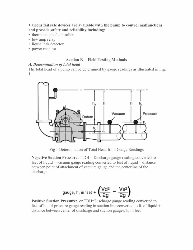
Section B -- Field Testing Methods A. Determination of total head The total head of a pump can be determined by gauge readings as illustrated in Fig. 1.
Fig 1 Determination of Total Head from Guage Readings
Negative Suction Pressure: TDH = Discharge gauge reading converted to feet of liquid + vacuum gauge reading converted to feet of liquid + distance between point of attachment of vacuum gauge and the centerline of the discharge
Positive Suction Pressure: or TDH=Discharge gauge reading converted to feet of liquid-pressure gauge reading in suction line converted to ft. of liquid + distance between center of discharge and suction gauges, h, in feet

In using gauges when the pressure is positive or above atmos-pheric pressure, any air in the gauge line should be vented off by loosening the gauge until liquid appears. This assures that the entire gauge line is filled with liquid and thus the gauge will read the pressure at the elevation of the centerline of the gauge. However, the gauge line will be empty of liquid when measuring vacuum and the gauge will read the vacuum at the elevation of the point of attachment of the gauge line to the pipe line. These assumptions are reflected in the above definitions.
The final term in the above definitions accounts for a difference in size between the suction and discharge lines. The discharge line is normally smaller than the suction line and thus the dis-charge velocity is higher. A higher velocity results in a lower pressure since the sum of the pressure head and velocity head in any flowing liquid remains constant. Thus, when the suction and discharge line sizes at the gauge attachment points are different, the resulting difference in velocity head must be in-cluded in the total head calculation.
Manometers can also be used to measure pressure. The liquid used in a manometer is normally water or mercury, but any liquid of known specific gravity can be used. Manometers are extremely accurate for determining low pressures or vacuums and no calibration is needed. They are also easily fabricated in the field to suit any particular application. Figs. 2 & 3 illustrate typical manometer set ups.
Fig. 2 Manometer Indicating Vacuum

Fig. 3 Manometer Indicating Pressure
B. Measurement of capacity a.) Magnetic Flow Meter A calibrated magnetic flow meter is an accurate means of measuring flow in a pumping system. However, due to the ex-pense involved, magnetic flow meters are only practical in small factory test loops and in certain process pumping systems where flow is critical. b.) Volumetric measurement Pump capacity can be determined by weighing the liquid pumped or measuring its volume in a calibrated vessel. This is often practical when pumping into an accurately measured reservoir or tank, or when it is possible to use small containers which can be accurately weighed. These methods, however, are normally suited only to relatively small capacity systems. c.) Venturi meter A venturi meter consists of a converging section, a short con-stricting throat section and then a diverging section. The object is to accelerate the fluid and temporarily lower its static pressure. The flow is then a function of the pressure differential between the full diameter line and the throat. Fig. 4 shows the general shape and flow equation. The meter coefficient is determined by actual calibration by the manufacturer and when properly installed the Venturi meter is accurate to within plus or minus 1%.

Fig. 4 Venturi Meter
d.) Nozzle A nozzle is simply the converging portion of a venturi tube with the liquid exiting to the atmosphere. Therefore, the same formula can be used with the differential head equal to the gauge read-ing ahead of the nozzle. Fig. 5 lists theoretical nozzle discharge flows.


e.) Orifice An orifice is a thin plate containing an opening of specific shape and dimensions. The plate is installed in a pipe and the flow is a function of the pressure upstream of the orifice. There are numerous types of orifices available and their descriptions and applications are covered in the Hydraulic Institute Standards and the ASME Fluid Meters Report. Orifices are not recommended for permanent installations due to the inherent high head loss across the plate.
Fig. 6 Weirs
f.) Weir A weir is particularly well suited to measuring flows in open conduits and can be adapted to extremely large capacity systems. For best accuracy, a weir should be calibrated in place. However, when this is impractical, there are formulas which can be used for the various weir configurations. The most common types are the rectangular contracted weir and the 90 V-notch weir. These are shown in Fig. 6 with the applicable flow formulas.
g.) Pitot tube A pilot tube measures fluid velocity. A small tube placed in the flow stream gives two pressure readings: one receiving the full impact of the flowing stream reads static head + velocity head, and the other reads the static head only (Fig. 7). The difference between the two readings is the velocity head. The velocity and the flow are then determined from the following well known formulas.
Capacity = Area x Average Velocity Since the velocity varies across the pipe, it is necessary to obtain a velocity profile to determine the average velocity.

This involves some error, but when properly applied a calibrated pilot tube is within plus or minus 2% accuracy.
Fig. 7 Pitot Tube
Section B -- Vibration Analysis Vibration analysis equipment enables you to tell when "normal" vibration becomes "problem" vibration or exceeds acceptable levels. It may also allow you to determine the source and cause of the vibration, thus becoming an effective preventive maintenance and troubleshooting aid. A vibration analyser measures the amplitude, frequency and phase of vibration. Also when vibration occurs at several frequencies, it separates one frequency from another so that each individual vibra-tion characteristic can be measured. The vibration pickup senses the velocity of the vibration and converts it into an electrical signal. The analyzer receives this signal, converting it to the corresponding amplitude and frequency. The amplitude is measured in terms of peak-to-peak displacement in mils (1 mil = .001") and is indicated on the amplitude meter. Some instruments are equipped with a frequency meter which gives a direct readout of the predominant frequency of the vibration. Other instruments have tunable filters which allow scanning the frequency scale and reading amplitude at any particular frequency, all others being filtered out. A strob light is used to determine the phase of vibration. It can be made to flash at the frequency of the vibration present or at any arbitrary frequency set on an internal oscillator. A reference mark on a rotating part viewed under the strob light flashing at the vibration frequency may appear as a single frozen (or rotat-ing) mark, or as several frozen (or rotating) marks. The number of marks viewed is useful in determining

the source of the vibration. The location of the mark or marks is used in balancing rotating parts. The first step in vibration analysis is to determine the severity of the vibration, then, if the vibration is serious, a complete set of vibration readings should be taken before attempting to analyze the cause. Fig. 1 is the typical guide for end suction stock pumps as published by the Hydraulic Institute. The amplitudes shown are the overall RMS obtained without filtering to specific frequencies. Amplitudes at specific frequencies, such as vane pass frequency with multi-vane impellers, should be less than 75% of the unfiltered amplitudes allowed in Fig. 1 at the operating RPM. For other pumps, refer to Hydraulic Institute standards or pump manufacturer.
Fig. 1 Acceptable Field Vibration Limits for Horizontal Pumps - Clear Liquid
(Rigid Structures) Severity of vibration is a function of amplitude and pump speed; however, it should be noted that a change in severity over a period of time is usually a

warning of impending failure. This change is often more important than vibration in the "slightly rough" or "rough" ranges which does not change with time.
Complete pump vibration analysis requires taking vibration readings at each bearing in three planes (horizontal, vertical and axial). Readings at the pump suction and discharge flanges may also be useful in some cases.
After all data has been tabulated, it can be analyzed to determine the most likely cause or causes of vibration and the identifying characteristics of each. By analyzing the tabulated vibration data one or several causes may be found. Each must be checked, starting with the most likely cause or easiest to check. For example, assume the axial vibration is 50% or more of the radial vibration and the predominant frequency is the same as the RPM of the pump. The chart indicates probable misalignment or bent shaft. Coupling misalignment is probably the most common single cause of pump vibration and is one of the easiest to check. If after checking, the alignment proves to be good, then inspect for flange loading. Finally, check for a bent shaft. Cavitation in a pump can cause serious vibration. Vibration at random frequencies can also be caused by hydraulic disturbances in poorly designed suction or discharge systems. The use of vibration equipment in preventative maintenance involves keeping a vibration history on individual pieces of equipment in a plant. A form similar to that shown in Fig 3 can be used to record the vibration data on a periodic routine basis. Abrupt changes are a sign of impending failure. A gradual increase in vibration can also be detected and corrective measures can be taken before it reaches a dangerous level.

Fig. 3 Vibration Identification Chart

Fig. 4 Vibration Data Sheet
Section B -- Pump Application Data 1. DATUM OR GRADE - The elevation of the surface from which the pump is supported.
2. STATIC LIQUID LEVEL - The vertical distance from grade to the liquid level when no liquid is being drawn from the well or source.
3. DRAWDOWN - The distance between the static liquid level and the liquid level when pumping at required capacity.
4. PUMPING LIQUID LEVEL - The vertical distance from grade to liquid level when pumping at rated cap-acity. Pumping liquid level equals static water level plus drawdown.
5. SETTING - The distance from grade to the top of the pump bowl assembly.
6. TPL (TOTAL PUMP LENGTH) - The distance from grade to lowest point of pump.
7. RATED PUMP HEAD - Lift below discharge plus head above discharge

plus friction losses in discharge line. This is the head for which the customer is responsible and does not include any losses within the pump.
8. COLUMN AND DISCHARGE HEAD FRICTION LOSS - Head loss in the pump due to friction in the column assembly and discharge head. Friction loss is measured in feet and is dependent upon column size, shaft size, setting, and discharge head size. Values given in appropriate charts in Data Section.
9. BOWL HEAD - Total head which the pump bowl assembly will deliver at the rated capacity. This is curve performance.
10. BOWL EFFICIENCY- The efficiency of the bowl unit only. This value is read directly from the performance curve.

11. BOWL HORSEPOWER- The horsepower - required by the bowls only to deliver a specified capacity against bowl head.
12. TOTAL PUMP HEAD - Rated pump head plus column and discharge head loss. Note: This is new or final bowl head.
13. SHAFT FRICTION LOSS - The horsepower required to turn the lineshaft in the bearings. These values are given in appropriate table in Data Section.
14. PUMP BRAKE HORSEPOWER - Sum of 'bowl horsepower plus shaft loss (and the driver thrust bearing loss under certain conditions).
15. TOTAL PUMP EFFICIENCY (WATER TO WATER) -The efficiency of the complete pump less.the driver, with all pump losses taken into account.
16. OVERALL EFFICIENCY (WIRE TO WATER)-The efficiency of the pump and motor complete. Overall efficiency = total pump efficiency X motor efficiency.
17. SUBMERGENCE-Distance from liquid level to suction bell.
Section B -- Vertical Turbine Pumps Turbine Nomenclature Vertical Turbine Pumps Calculating Axial Thrust Under normal circumstances Vertical Turbine Pumps have a thrust load acting parallel to the pump shaft. This load is due to unbalanced pressure, dead weight and liquid direction change. Optimum selection of the motor bearing and correct determination of required bowl lateral for deep setting pumps require accurate knowledge of both the magnitude and direction (usually down) of the resultant of these forces. In addition, but with a less significant role, thrust influences shaft H.P. rating and shaft critical speeds.

IMPELLER THRUST Impeller Thrust in the downward direction is due to the unbalanced discharge pressure across the eye area of the impeller. See diagram A.
Counteracting this load is an upward force primarily due to the change in direction of the liquid passing through the impeller. The resultant of these two forces constitutes impeller thrust. Calculating this thrust using a thrust constant (K) will often produce only an approximate thrust value because a single constant cannot express the upthrust component which varies with capacity.
To accurately determine impeller thrust, thrust-capacity curves based on actual tests are required. Such curves now exist for the "A" Line. To determine thrust, the thrust factor "K" is read from the thrust-capacity curve at the required capacity and given RPM. "K" is then multiplied by the Total Pump Head (Final Lab Head) times Specific Gravity of the pumped liquid. If impeller thrust is excessively high, the impeller can usually be hydraulically balanced. This reduces the value of "K". Balancing is achieved by reducing the discharge pressure above the impeller eye by use of balancing holes and rings. See diagram B.
NOTE: Although hydraulic balancing reduces impeller thrust, it also decreases efficiency by 1 to 5 points by providing an additional path for liquid recirculation.