“Magnetic damping”: Quantitative experiments with MBL sensors · “Magnetic damping”:...
9
GIREP-ICPE-MPTL Conference 2010, Reims “Magnetic damping”: Quantitative experiments with MBL sensors Pasquale Onorato and Anna De Ambrosis [email protected] Department of Physics ”A. Volta”, University of Pavia, via Bassi 6, I-27100 Pavia, Italy Abstract We propose a sequence of experiments with the goal of exploring electromagnetic induction phenomena and “magnetic friction” forces. The experiments have been tested with high school students in the context of a program of cooperation between our Physics Department and the Regional School District. The experiments involve permanent magnets and conductors (a coil of wire or an aluminium plate) in relative motion. Motion and current-voltage online sensors allow real time measurements of position, velocity and induced voltage and provide graphs of these quantities vs time. The role played by the intensity of the induced current in determining the damping of oscillations due to the “magnetic braking” is stressed. To this aim the coil is connected to an external circuit with a variable resistance and students can observe how the damping of the oscillations increases when the circuit resistance decreases and can relate the variation of the mechanical energy of the system to the production of thermal energy in the circuit. 1. Introduction Electromagnetic induction is a significant subject in college and undergraduate physics courses and it is extremely difficult for most students [1]. Unlike mechanics, where many situations involve familiar macroscopic objects, more abstract concepts such as field and flux [2] are often discouraging for students. Moreover several studies have emphasized students’ conceptual troubles in understanding the role of magnetic field flux and its time variation [3- 6] in experimental configurations. Both demonstrations [7] and experiments [8-10] about electromagnetic induction have been designed to help students overcome their learning problems while some recent studies analyzed both from a theoretical and experimental point of view the magnetic braking[11-14]. In this paper we propose an experimental approach to the study of magnetic induction which starts from the observation of the magnetic braking force acting on a moving conductor (a coil of wire or an aluminium plate) as it passes between the poles of a permanent magnet. The behaviour of this complex system is modelled by means of a sequence of experiments aimed at: o studying from a quantitative point of view the characteristics of the force acting on a metallic sheet entering and exiting from a region where a magnetic field is present; o analyzing the role of ohmic resistance in establishing the strength of magnetic braking on a conductor moving in a magnetic field. For this purpose a simple experimental set up is used where the ohmic resistance of the conductor can be easily varied. An interpretation of the experimental results is given from the energy point of view by comparing the transfer of mechanical energy in thermal energy through electrical resistive dissipation with the work done by a viscous like friction force. This approach allows students to understand how the magnetic braking depends on the value of the resistance in the circuit and to correlate the theoretical model to the experimental results.
Transcript of “Magnetic damping”: Quantitative experiments with MBL sensors · “Magnetic damping”:...
GIREP-ICPE-MPTL Conference 2010, Reims
“Magnetic damping”: Quantitative experiments with MBL
sensors
Pasquale Onorato and Anna De Ambrosis
Department of Physics ”A. Volta”, University of Pavia, via Bassi 6, I-27100 Pavia, Italy
Abstract
We propose a sequence of experiments with the goal of exploring electromagnetic induction
phenomena and “magnetic friction” forces. The experiments have been tested with high
school students in the context of a program of cooperation between our Physics Department
and the Regional School District.
The experiments involve permanent magnets and conductors (a coil of wire or an aluminium
plate) in relative motion. Motion and current-voltage online sensors allow real time
measurements of position, velocity and induced voltage and provide graphs of these quantities
vs time.
The role played by the intensity of the induced current in determining the damping of
oscillations due to the “magnetic braking” is stressed. To this aim the coil is connected to an
external circuit with a variable resistance and students can observe how the damping of the
oscillations increases when the circuit resistance decreases and can relate the variation of the
mechanical energy of the system to the production of thermal energy in the circuit.
1. Introduction
Electromagnetic induction is a significant subject in college and undergraduate physics
courses and it is extremely difficult for most students [1]. Unlike mechanics, where many
situations involve familiar macroscopic objects, more abstract concepts such as field and flux
[2] are often discouraging for students. Moreover several studies have emphasized students’
conceptual troubles in understanding the role of magnetic field flux and its time variation [3-
6] in experimental configurations.
Both demonstrations [7] and experiments [8-10] about electromagnetic induction have been
designed to help students overcome their learning problems while some recent studies
analyzed both from a theoretical and experimental point of view the magnetic braking[11-14].
In this paper we propose an experimental approach to the study of magnetic induction which
starts from the observation of the magnetic braking force acting on a moving conductor (a coil
of wire or an aluminium plate) as it passes between the poles of a permanent magnet. The
behaviour of this complex system is modelled by means of a sequence of experiments aimed
at:
o studying from a quantitative point of view the characteristics of the force acting on a
metallic sheet entering and exiting from a region where a magnetic field is present;
o analyzing the role of ohmic resistance in establishing the strength of magnetic braking
on a conductor moving in a magnetic field. For this purpose a simple experimental set
up is used where the ohmic resistance of the conductor can be easily varied.
An interpretation of the experimental results is given from the energy point of view by
comparing the transfer of mechanical energy in thermal energy through electrical resistive
dissipation with the work done by a viscous like friction force. This approach allows students
to understand how the magnetic braking depends on the value of the resistance in the circuit
and to correlate the theoretical model to the experimental results.

GIREP-ICPE-MPTL Conference 2010, Reims
2
The experiments were carried out by employing on-line sensors (Microcomputer Based
Laboratory) to acquire data and to create graphs in real time. The activities are designed to
create an environment where students gain experience of electromagnetic phenomena.
Students can recognize how the variation of the flux of B field is the quantity always involved
in these phenomena and for this reason it is the quantity used to describe and to interpret
them.
2. The “magnetic friction force”
When a non-ferromagnetic metallic plate passes between the poles of a magnet, eddy currents
are induced in the conductor as the plate enters and exits from the field (Figure 1, left). The
action of the magnetic field on the induced currents produces a braking force. The problem
posed to the students is: what kind of forces act on the conductor?
To explore this phenomenon students are invited to use an equipment which allows to
quantify the force acting on the metallic sheet and to study its properties: the aluminium plate,
mass m, is now pulled through the magnetic field by a falling mass M as in a kind of Atwood
machine (Figure1, right).
Figure 1 - Experimental apparatus to measure the strength of the “magnetic friction force”
(Right) A metallic sheet of mass m, is connected by a string over a pulley to a falling mass M
and is pulled through a magnetic field. (Middle) A motion sensor on the floor gives the
position as a function of time of the sheet moving through the magnetic field. (Right) The
different phases during the motion: an accelerated motion when the sheet is completely inside
(I) or completely outside (III) the magnetic field region, and a motion governed by the
competitive effects of the tension force and the magnetic braking force when the sheet is
partially outside (II).
Thanks to the measurements made with a motion sensor [15], graphs of position versus time
are obtained (Figure 2). Three different phases (Figure 1.Right) can be recognized in the
movement of the metallic sheet: an accelerated motion when the conductor is completely
inside the magnet, a uniform motion with a drift velocity vd when the plate is partially inside,
an accelerated motion when the sheet is completely outside. Thus students observe the

GIREP-ICPE-MPTL Conference 2010, Reims
3
presence of a “braking force” only when the sheet is exiting from the magnetic field. When
the motion of the sheet is uniform this force has the same value as the tension force,
mgmM
mMmaF TT
+
−==
.
By changing M it is possible to study the relation between FT and the drift velocity vd reached
by the sheet and measured by the motion sensor. Experimental data, reported in Figure 2
Right, show the linear dependence of vd on FT. We can argue that a linear relation exists also
between the magnetic friction force and the drift velocity, so we can characterize the magnetic
damping as due to a viscous friction force, that can be expressed as:
vmvbFFrictionViscous
rrrβ−=−= (1)
Figure 2 - (Left) Position versus time plot obtained with a motion sensor. The presence of a
“friction force” which causes a uniform motion is observable when the sheet is exiting from
the magnetic field.(Right) Experimental values of the drift velocity of the conductor obtained
for increasing values of the driving force FT. Data are fitted by a linear relation according the
rule vd=FT/(βm)
3. The role of the ohmic resistance
To explore the energy transfer connected with the action of the magnetic braking force a
different experimental apparatus is proposed. A metallic plate oscillates in the magnetic field
produced by two permanent magnets. Students observe the strong damping of this eddy
current pendulum, also known as Waltenhofen’s Pendulum, and are requested to explain why
does the mechanical energy decrease.
The role played by the intensity of the induced current in determining the damping of the
pendulum is studied by substituting the aluminium plate with a coil oscillating in the magnetic
field and connected to an external circuit whose resistance can be varied (see Figure 3,
Middle). Motion and current/voltage sensors allow measure the amplitudes of the oscillations,
the velocity of the coil pendulum, the electromotive force and the current induced in the coil.
Graphs of position vs time are obtained in real time (Figure 3, Right).
GIREP-ICPE-MPTL Conference 2010, Reims
4
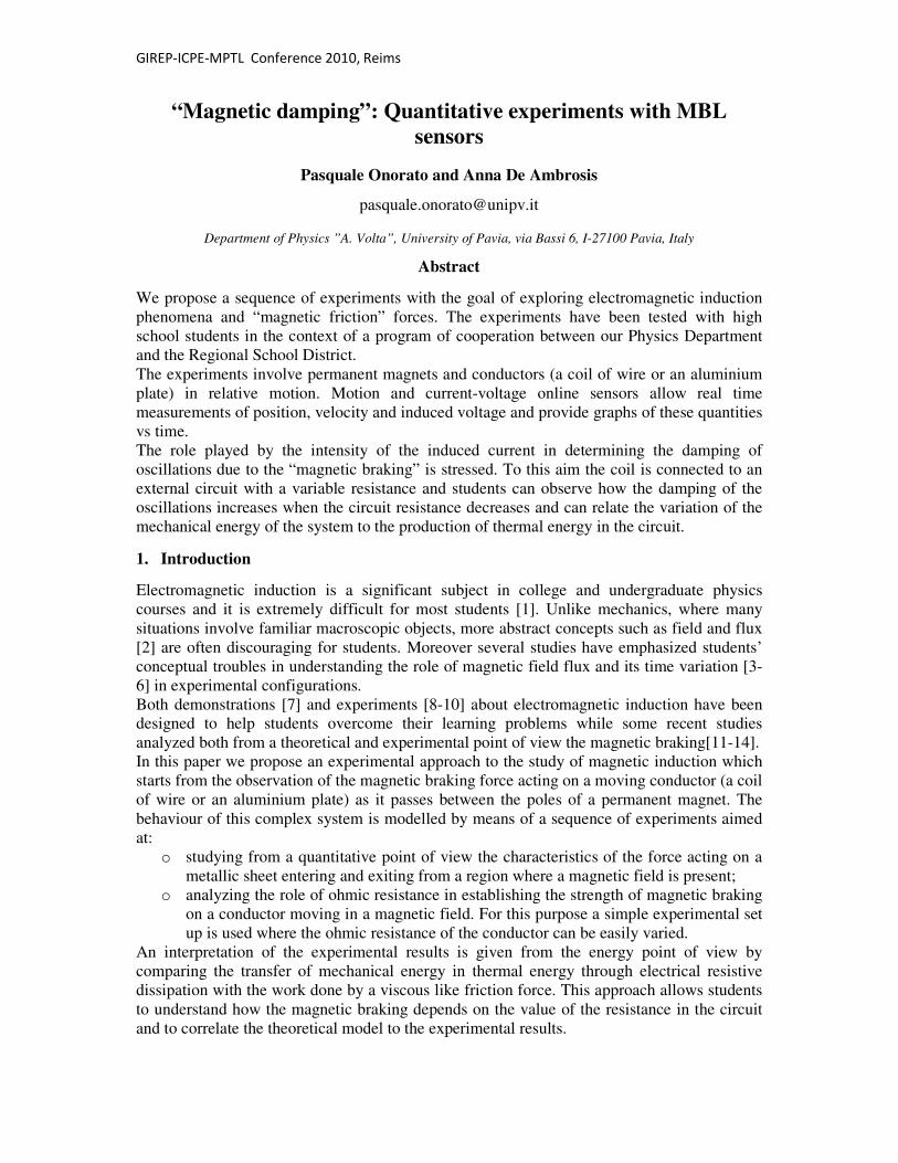
Figure 3 - Experimental set up(Left) and its schematic representation(Middle). (Right)
Graphs of position versus time for different values of the shunt resistance.
The role played by the resistance of the circuit (and then by the intensity of the induced
current) in determining the damping of the oscillations of the coil pendulum, due to the
magnetic friction force, is stressed. Students observe how the damping of the oscillations
increases when the circuit resistance decreases. This is for most of the students an unexpected
result.
If the students have already studied the motion of a harmonic oscillator damped by viscous
friction forces it is possible to extend the analysis and find a relation between the viscous
friction coefficient β and the shunt resistance R.
According to the theory, the angular position versus time of a pendulum, damped by a viscous
friction force, is described by the equation )cos(]2
exp[)( 0 tt
t ωβϑϑ −= where
4
22
0
γωω −= and 0ω is the frequency of the un-damped oscillator. It follows that, in the
hypotheses of small oscillation amplitude and friction force proportional to the velocity, the
relation between the amplitude and the number n, of the accomplished oscillations is
]exp[0 nn λϑϑ −= where T2
βπ
ω
βλ == .
By using the graphs reported in Figure 3 students can find, for each value of the resistance,
the amplitude of the oscillations at different time values and plot nϑ versus n, (Figure 4, Left).
The data are fitted by exponential curves and the damping factor λ is obtained for the three
value of the resistance, R=1 Ω, R=2 Ω, R=∞ (open circuit).

GIREP-ICPE-MPTL Conference 2010, Reims
5
Figure 4 - The amplitudes of the oscillations of the magnet are reported as function of the
number n of the accomplished oscillations for different values of the resistance R of the
circuit (Left). Experimental values of the viscous friction coefficient are reported for
different values of the resistance R. The data fit with the relation in eq.(2) (Right).
The plot in Fig. 4.Right shows how the experimental values fit with a relation
R
0κββ += ∞ , (2)
where 0κ is a constant while β∞ includes the contribution to the damping of air resistance,
sliding friction at the pivot etc. In this way students verify that the damping of the oscillations
and the coefficient β increase when the circuit resistance decreases.
4. The energy point of view
The energy point of view can be used not only to give a qualitative interpretation of the
experimental results (the loss of the mechanical energy of the conductor can be explained
with the increase of the internal energy of the circuit, where a resistive thermal conversion
takes place), but also to derive a quantitative explanation. In particular, the theoretical relation
between the resistance R and the magnetic friction coefficient β can be obtained and
compared with the experimental results. At this aim we consider a simple system constituted
by a wire loop which enters with velocity v into a region where a uniform magnetic field is
present (Figure 5).
GIREP-ICPE-MPTL Conference 2010, Reims
6
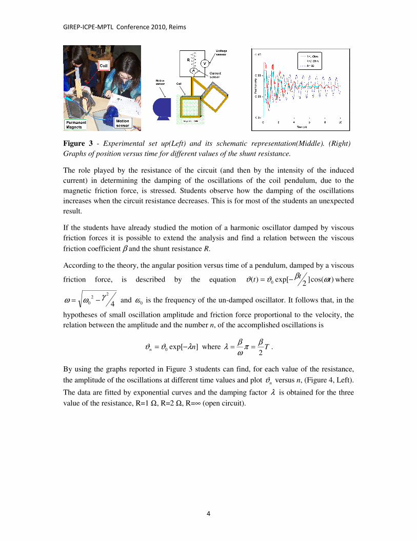
Figure 5 - Schematic plot of a wire loop which enters in a uniform magnetic field with
staring speed v. When the coil moves fully outside or fully inside the region where the
magnetic field is present no current flows in the wire. When the coil is just partially inside
the region with magnetic field, the magnetic flux changes and the induced emf produces a
current flowing in the wire.
The wire has a mechanical energy proportional to v2. When the magnetic flux through the
surface bounded by the wire loop changes an electromotive force (emf) is produced along the
closed path of the wire. Since the emf is proportional to the rate of change of the magnetic
flux, according to the laws of the electromagnetic induction,
,),(
BLvdt
dyBL
dt
tBdemf =−=
Φ−=
(3)
where L is the length of the wire side perpendicular to v. In the closed circuit with resistance
R a current flows and an increase of the internal energy of the wire loop takes place at rate
Remf
J RIP22 == , corresponding to the power dissipated by the circuit. As a consequence the
mechanical energy is reduced at the same rate:
222222 1)(1
vR
LB
dt
dyBL
Rdt
Bd
RR
emfPJ =
=
Φ== . (4)
This corresponds to the work performed during a second by a force vMFmf
rrβ−= with
MR
LB22
=β (5).
In this way the phenomenological law expressed by equation (1) is obtained, together with the
theoretical dependence of the viscous friction coefficient on the resistance. The experimental

GIREP-ICPE-MPTL Conference 2010, Reims
7
results reported in Figure 4 and eq.(2), agree with the theoretical prediction given by equation
(5).
5. Using the experiments with students
The experiments have been tested with high school students and with student teachers in a
postgraduate course for physics teacher education. The students carried out the experimental
activities in groups of four and the activity sequence was developed according to the phases
reported in Fig.6. Asking questions and stimulating a discussion before and after each
experiment encouraged the students to think critically and to maintain a high level of interest.
Figure 6 - The students carried out the experimental activities in groups of four and
completed the experimental work in a session of three-four hours. One or two assistants
(generally master students) worked as facilitators. The organization of the activities:
students spent a large portion of their laboratory time observing, interpreting and discussing
the experimental results with their peers.
Data collected during students’ activity show a progression of students’ ideas during the
development of the sequence
• The design of the experiment on the Atwood machine gave the students the possibility
of easily distinguishing the three phases of the motion and perceiving when the
magnetic force was active.
• Students recognized that the magnetic force has the same dependence on the velocity
as a viscous friction force.
• The evidence of braking forces in the experiments revealed to be a strong motivation
for students to investigate carefully and in a quantitative way the effects of
electromagnetic induction.
By discussing students’ interpretations during and after the activity sequence we found that:
• The majority of the students evoked generically Lenz’s law by referring only to the
magnetic field (without considering the induced currents). This way of using Lenz’s
law might cause a misleading interpretation of the magnetic force. Students who think
that field lines are real lines which can interact with each other often consider the force

GIREP-ICPE-MPTL Conference 2010, Reims
8
as produced by the interaction between two magnetic fields, the induced one and the
one generated by the permanent magnets.[16]
• Some students identified the induced emf with the braking force, by interpreting the
electromotive force as a real force.
• Other students (a minority) tried to give a description of the braking magnetic force
only by using Lorentz’ force. They attributed to the Lorentz’ force the character of
damping force, thus arriving to the paradoxical consequence of attributing to this force
the possibility of doing work, neglecting the role of the electrical resistance.[17,18]
• Based on the well known relation W = I2R, many students were initially convinced
that the damping of the oscillations would increase with the resistance. They
spontaneously did not recognize that the variation of the resistance produced a
variation of the current and that this variation strongly affected the resistive
dissipation. Discussion after the experiment allowed the majority of the students to
reflect on this point and on the meaning of the relation W = I2R.
We interviewed many of the students who participated in the laboratory activities asking them
an evaluation of their experience. They especially emphasized as positive the opportunity of
setting up by themselves the experimental apparatuses, doing the measurements and
proposing alternative experiments. Students appreciated that the study of the magnetic force
was based on the investigation of physical phenomena rather than on the manipulation of
abstract formulas in a textbook.
Some of them also remarked “These physical phenomena are quite impressive in fact we were
always surprised about what really happened”
Some students observed how a good experimental analysis requires many concepts usually
learned in different moments of the scholar instruction. One student wrote “the experiment is
quite simple to be realized, because we used very common materials (magnets, coils, metallic
sheets,…) but it is very hard to be understood. It was the most complex experience of our
physics course”. One other noted “The explanation of the physical phenomena was quite
difficult and we discussed several different proposals to explain what happened”.
References
[1] DarrenWong, Paul Lee and See Kit Foong A datalogger demonstration of electromagnetic induction with a
falling, oscillating and swinging magnet PHYSICS EDUCATION 45, 394 2010
[2] Chabay R and Sherwood B 2006 Restructuring the introductory electricity and magnetism course Am. J.
Phys. 74 329–35
[3] Galili I and Kaplan D (1997) Changing approach to teaching electromagnetism in a conceptually oriented
introductory physics course Am. J. Phys. 65 (7), 657-667.
[4] Albe V, Venturini P and Lascours J (2001) Electromagnetic Concepts in Mathematical Representation of
Physics, Journal of Science Education and Technology, 10 (2)
[5] Bagno E and Eylon B S (1997) "From Problem Solving to a knowledge structure: An example from the
domain of electromagnetism," Am. J. Phys. 65 (8) 726-736.
[6]Thong W M and Gunstone R (2008) Some student beliefs about electromagnetic induction. Research in
Science Education,Res. Sci. Educ. 38, 31-44.
[7] Nicklin R C (1986) ‘‘Faraday’s Law—Qualitative Experiments,’’ Am. J. Phys. 54, 422–428.
[8] Kingman R, Rowland S C, and Popescu S, (2002) An experimental observation of Faraday’s law of
induction Am. J. Phys. 70 595-598.

GIREP-ICPE-MPTL Conference 2010, Reims
9
[9] MacLatchy C. S., Backman P., and Bogan L., (1993) ‘‘A quantitative magnetic breaking experiment,’’ Am.
J. Phys. 61, 1096–1101.
[10] Carpena P., (1997) ‘‘Velocity measurements through magnetic induction,’’ Am. J. Phys. 65, 135–140.
[11] L. H. Cadwell, “Magnetic damping: Analysis of an eddy current brake using an airtrack,” Am. J. Phys. 64,
917-923 (1996).
[12] X. Xie, Z. Wang, P. Gu, Z. Jian, X. Chen, and Z. Xie,, “Investigation of magnetic damping on an air track,”
Am. J. Phys. 74, 974-978 (2006).
[13]A. Vidaurre, J. Riera, J. A Monsoriu and M. H Gimenez, “Testing theoretical models of magnetic damping
using an air track,” Eur. J. Phys. 29, 335–343 (2008).
[14]A. Bonanno, G. Bozzo, M. Camarca and P. Sapia, “Foucault dissipation in a rolling cylinder: a webcam
quantitative study, ” Eur. J. Phys. 32, 419-429 (2011).
[15] www.pasco.com
[16] J. Guisasola, J. M. Almudí, and K.Zuza, “The design and evaluation of an instructional sequence on
Ampere’s law,” Am. J. Phys. 78, 1207-1217 (2010).
[17] E. P. Mosca, “Magnetic forces doing work?,” Am. J. Phys. 42, 295-297 (1974).
[18]J. A. Redinz, “Forces and work on a wire in a magnetic field,” Am. J. Phys. 79, 774-776 (2011).


![Modeling and experiments on eddy current damping · PDF fileConcepts of eddy current damping. Fig. 2. Eddy current shock absorber by Kwag et al. [19]. cept of making an eddy current](https://static.fdocuments.in/doc/165x107/5a72ad247f8b9ab6538daf79/modeling-and-experiments-on-eddy-current-damping-pdf-fileconcepts-of-eddy-current.jpg)