
Magnetic Contactors and Thermal Overload Relays SK Series · Thermal Overload Relay Size (mm) Type...
68
MOTOR CONTROL Magnetic Contactors and Thermal Overload Relays SK Series 62C1-E-0022b
Transcript of Magnetic Contactors and Thermal Overload Relays SK Series · Thermal Overload Relay Size (mm) Type...

MOTOR CONTROL
Magnetic Contactors and Thermal Overload Relays
SK Series
62C1-E-0022b

2
SK Series Lineup
Motor ratings
AC-3,AC400V
SK06: 2.2 kW SK18: 7.5 kW SK32: 15 kWSK09: 4 kW SK22: 11 kWSK12: 5.5 kW
Magnetic
Contactor
Size (mm)
TypeSK06
SK09
SK12
SK18
SK22
SK32
Thermal
Overload Relay
Size (mm)
Type TK12 TK25 TK26
Magnetic Contactor and Thermal Overload Relay
SK SeriesSupporting the market for motor drive circuits such as inverters and servos
With the recent increased popularity of inverters and servo amplifiers, more companies are using
magnetic contactors as primary side switches for drive control devices as well as using them as direct
input motor drives (AC-3 category).
The SK Series was created to fill the need for magnetic contactors with optimized performance and
specifications required for this kind of application.
81
81 (AC coil)94 (DC coil)
45
48
49
45
81
81 (AC coil) 94 (DC coil)
53
45 53 53
3
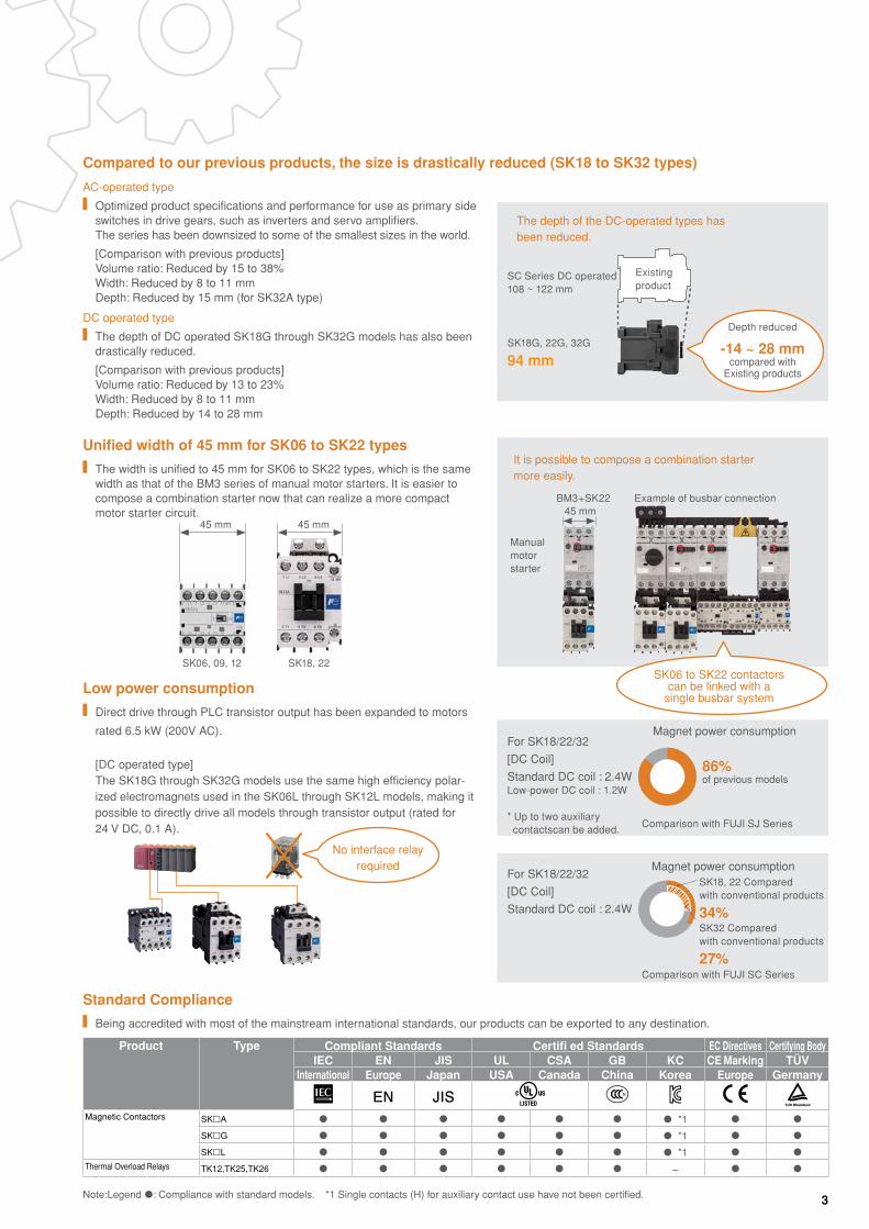
No interface relay required
Low power consumption
Direct drive through PLC transistor output has been expanded to motors
rated 6.5 kW (200V AC).
Standard Compliance
Being accredited with most of the mainstream international standards, our products can be exported to any destination.
For SK18/22/32
[DC Coil]
Standard DC coil : 2.4W
SK18, 22 Compared with conventional products
34%SK32 Compared with conventional products
27%
Magnet power consumption
For SK18/22/32
[DC Coil]
Standard DC coil : 2.4WLow-power DC coil : 1.2W * Up to two auxiliary contactscan be added.
Comparison with FUJI SJ Series
Comparison with FUJI SC Series
86% of previous models
Magnet power consumption
Product Type Compliant Standards Certifi ed Standards EC Directives Certifying BodyIEC EN JIS UL CSA GB KC CE Marking TÜV
International Europe Japan USA Canada China Korea Europe Germany
EN JISMagnetic Contactors SKA *1
SKG *1
SKL *1
Thermal Overload Relays TK12,TK25,TK26 −
Note:Legend : Compliance with standard models. *1 Single contacts (H) for auxiliary contact use have not been certified.
[DC operated type] The SK18G through SK32G models use the same high efficiency polar-ized electromagnets used in the SK06L through SK12L models, making it possible to directly drive all models through transistor output (rated for 24 V DC, 0.1 A).
Unified width of 45 mm for SK06 to SK22 types
The width is unified to 45 mm for SK06 to SK22 types, which is the same width as that of the BM3 series of manual motor starters. It is easier to compose a combination starter now that can realize a more compact motor starter circuit.
AC-operated type
Optimized product specifications and performance for use as primary side switches in drive gears, such as inverters and servo amplifiers. The series has been downsized to some of the smallest sizes in the world.
[Comparison with previous products] Volume ratio: Reduced by 15 to 38% Width: Reduced by 8 to 11 mm Depth: Reduced by 15 mm (for SK32A type)
DC operated type
The depth of DC operated SK18G through SK32G models has also been drastically reduced.
[Comparison with previous products] Volume ratio: Reduced by 13 to 23% Width: Reduced by 8 to 11 mm Depth: Reduced by 14 to 28 mm
45 mm
SK06, 09, 12
45 mm
SK18, 22
Existingproduct
SC Series DC operated108 ~ 122 mm
SK18G, 22G, 32G
94 mm
The depth of the DC-operated types has been reduced.
Depth reduced
-14 ~ 28 mm compared with
Existing products
It is possible to compose a combination starter more easily.
Manualmotorstarter
Example of busbar connectionBM3+SK22
SK06 to SK22 contactors can be linked with a
single busbar system
45 mm
Compared to our previous products, the size is drastically reduced (SK18 to SK32 types)
4
Catalog DisclaimerThe information contained in this catalog does not constitute an express or implied warranty of quality, any warranty of merchantability of fitness for a particular purpose is hereby disclaimed.
Since the user's product information, specific use application, and conditions of use are all outside of Fuji Electric FA Components & Systems'control, it shall be the responsibility of the user to determine the suitability of any of the products mentioned for the user's application.
One Year Limited WarrantyThe products identified in this catalog shall be sold pursuant to the terms and conditions identified in the"Conditions of Sale" issued by Fuji Electric FA with each order confirmation.
Except to the extent otherwise provided for in the Conditions of Sale issued by Fuji Electric FA, Fuji Electric FA warrants that the Fuji Electric FA products identified in this catalog shall be free from significant defects in materials and workmanship provided the product has not been: 1) repaired or altered by others than Fuji Electric FA; 2) subjected to negligence, accident, misuse, or damage by circumstances beyond Fuji Electric FA's control; 3) improperly operated, maintained or stored; or 4) used in other than normal use or service. This warranty shall apply only to defects appearing within one (1) year from the date of shipment by Fuji Electric FA, and in such case, only if such defects are reported to Fuji Electric FA within thirty (30) days of discovery by purchaser. Such notice should be submitted in writing to Fuji Electric FA at 5-7, Nihonbashi Odemma-cho, Chuo-ku, Tokyo, Japan. The sole and exclusive remedy with respected to the above warranty whether such claim is based on warranty, contract, negligence, strict liability or any other theory, is limited to the repair or replacement of such product or, at Fuji Electric FA's option reimbursement by Fuji Electric FA of the purchase price paid to Fuji Electric FA for the particular product. Fuji Electric FA does not make any other representations or warranties, whether oral or in writing, expressed or implied, including but not limited to any warranty regarding merchantability or fitness for a particular purpose. Except as provided in the Conditions of Sale, no agent or representative of Fuji Electric FA is authorized to modify the terms of this warranty in writing or orally. In no event shall Fuji Electric FA be liable for special, indirect or consequential damages, including but not limited to, loss of use of the product, other equipment, plant and power system which is installed with the product, loss of profits or revenues, cost of capital, or claims against the purchaser or user of the product by its customers resulting from the use of information, recommendations and descriptions contained herein. The purchaser agrees to pass on to its customers and users, in writing at the time inquiries and orders are received by buyer, Fuji Electric FA's warranty as set forth above.
Safety Considerations• Operate (keep) in the environment specified in the operating instructions and manual. High temperature, high humidity,
condensation, dust, corrosive gases, oil, organic solvents, excessive vibration or shock might cause electric shock, fire, erratic operation or failure.
• For safe operation, before using the product read the instruction manual or user manual that comes with the product carefully or consult the Fuji sales representative from which you purchased the product.
• Products introduced in this catalog have not been designed or manufactured for such applications in a system or equipment that will affect human bodies or lives.
• Customers, who want to use the products introduced in this catalog for special systems or devices such as for atomic-energy control, aerospace use, medical use, passenger vehicle, and traffic control, are requested to consult with Fuji Electric FA.
• Customers are requested to prepare safety measures when they apply the products introduced in this catalog to such systems or facilities that will affect human lives or cause severe damage to property if the products become faulty.
• For safe operation, wiring should be conducted only by qualified engineers who have sufficient technical knowledge about electrical work or wiring.
• Follow the regulations of industrial wastes when the product is to be discarded.• For further questions, please contact your Fuji sales representative or Fuji Electric FA.

5
Magnetic-ContactorsSK Series
Page
Standard Models ......................................................................................................................................................................... 6Production Models ...................................................................................................................................................................... 8Type Number Nomenclature (Magnetic Contactors, Thermal Overload Relays and Auxiliary Relays) ....................................... 9Ratings Main Circuit Ratings ............................................................................................................................................................ 11 Auxiliary Circuit Ratings....................................................................................................................................................... 12 Operating Coil Voltages ....................................................................................................................................................... 13 Operating Coil Characteristics ............................................................................................................................................. 14 Performances ...................................................................................................................................................................... 15 AC-3 Breaking Current and Electrical Durability .................................................................................................................. 15 AC-1 Breaking Current and Electrical Durability .................................................................................................................. 16Protective Coordination Coordination with Short-circuit Protection Devices (SCPD) (Based on IEC and JIS Standards) ........................................ 17 UL approved Short-circuit Current Ratings (SCCR) ............................................................................................................ 21 Application to IE3 (Premium Efficiency) Motors .................................................................................................................. 27Normal Operating Conditions and Mounting ............................................................................................................................. 28Wiring ........................................................................................................................................................................................ 30Handling .................................................................................................................................................................................... 32Magnetic Contactors Features .............................................................................................................................................................................. 34 Ordering Information ........................................................................................................................................................... 34 Ratings and Types ............................................................................................................................................................... 34 Dimensions and Connection Diagrams ............................................................................................................................... 36Reversing Magnetic Contactors Features .............................................................................................................................................................................. 38 Ordering Information ........................................................................................................................................................... 38 Ratings and Types ............................................................................................................................................................... 38 Dimensions and Connection Diagrams ............................................................................................................................... 40 Main contact 4-pole magnetic contactor .............................................................................................................................. 42 Magnetic contactor with tab terminal ................................................................................................................................... 43 PC board mounting magnetic contactor .............................................................................................................................. 44Thermal Overload Relays Features .............................................................................................................................................................................. 45 Ordering Information ........................................................................................................................................................... 45 Ratings and Types ............................................................................................................................................................... 45 Ampere Setting Range Specification Codes ....................................................................................................................... 45 Auxiliary Circuit Ratings....................................................................................................................................................... 46 Operating Characteristics (Specifications) .......................................................................................................................... 46 Operating Characteristics Curves (Average Values) ........................................................................................................... 47 Dimensions and Connection Diagrams ............................................................................................................................... 48Optional Unit Type Numbers and Product Codes...................................................................................................................................... 49 Auxiliary Contact Blocks ...................................................................................................................................................... 50 Mechanical Interlock Unit and Power Connection Kit for Reversing .................................................................................... 54 Main Circuit Surge Suppression Unit and Separate Installation Unit .................................................................................. 55 Coil Surge Suppression Units and Operation Indicator Lamps ........................................................................................... 57 Thermal Overload Relay Reset Releases ........................................................................................................................... 59 Separate Mounting Unit for Thermal Overload Relay .......................................................................................................... 60 Link Module and Power Connection Kit for Reversing (Insert) ............................................................................................ 62Auxiliary Relays ......................................................................................................................................................................... 64

66
Magnetic-Contactors
Information subject to change without notice
Standard ModelsSeries SK Series
Frame 06 09 12
Magnetic Contactor appearance
(KKD14-157)
Thermal Overload Relay appearance
(KKD14-166)
Type Magnetic Contactors
AC-operated types SK06A SK09A SK12ADC-operated types (2.4W)
SK06G SK09G SK12G
DC-operated types (1.2W)
SK06L SK09L SK12L
Thermal Overload Relay TK12
Rated insulation voltage (IEC) 690V 690V 690V
Rated impulse withstand voltage (IEC) 6kV 6kV 6kV
Rated frequency 50-60Hz 50-60Hz 50-60Hz
Main circuit ratings
3-phase squirrel-cage motor capacity[kW] AC-3
IEC60947-4-1
200-240V
1.5kW 2.2kW 3kW
380-440V
2.2kW 4kW 5.5kW
500-550V
3kW 4kW 5.5kW
600-690V
3kW 4kW 4kW
Rated current Ie[A] AC-3
200-240V
6A 9A 12A
380-440V
6A 9A 12A
500-550V
5A 7A 9A
600-690V
3.5A 5A 5A
Conventional free air thermal current (Rated continuous current) Ith [A]
20A 20A 20A
Performances Operating cycles per hour [times/hour] 1800 1800 1800
Durability Mechanical 10 million 10 million 10 million
Electrical (AC-3) 1 million 1 million 1 million
Dimensions W×H×D [mm] 45×48×49 45×48×49 45×48×49
Options Auxiliary Contact Blocks
Front mounting (2-pole) ◎Front mounting (4-pole) *1 ◎
Mechanical Interlock Unit ◎Coil Surge Suppression Unit ◎Main Circuit Surge Suppression Unit ◎
Standards
Note: *1 These products cannot be combined with the SK□L.
Standard Models

77
SK SeriesMagnetic-Contactors
Information subject to change without notice
Standard ModelsSeries SK Series
Frame 18 22 32
Magnetic Contactor appearance
(KKD14-083) (KKD14-179)
Thermal Overload Relay appearance
(KKD14-095) (KKD14-113)
Type Magnetic Contactors
AC-operated types SK18A SK22A SK32ADC-operated types (2.4W)
SK18G SK22G SK32G
DC-operated types (1.2W)
− − −
Thermal Overload Relay TK25 TK26
Rated insulation voltage (IEC) 690V 690V 690V
Rated impulse withstand voltage (IEC) 6kV 6kV 6kV
Rated frequency 50-60Hz 50-60Hz 50-60Hz
Main circuit ratings
3-phase squirrel-cage motor capacity[kW] AC-3
IEC60947-4-1
200-240V
4.5kW 5.5kW 7.5kW
380-440V
7.5kW 11kW 15kW
500-550V
7.5kW 11kW 15kW
600-690V
7.5kW 7.5kW 11kW
Rated current Ie[A] AC-3
200-240V
18A 22A 32A
380-440V
18A 22A 32A
500-550V
13A 17A 24A
600-690V
9A 9A 15A
Conventional free air thermal current (Rated continuous current) Ith [A]
32A 32A 40A
Performances Operating cycles per hour [times/hour] 1800 1800 1200
Durability Mechanical 5 million 5 million 5 million
Electrical (AC-3) 1 million 1 million 1 million
Dimensions W×H×D [mm] AC-operated 45×81×81 45×81×81 53×81×81
DC-operated 45×81×94 45×81×94 53×81×94
Options Auxiliary Contact Blocks
Front mounting (2-pole) ◎Front mounting (4-pole) −Side-mounting ◎
Mechanical Interlock Unit ◎Coil Surge Suppression Unit ◎Main Circuit Surge Suppression Unit ◎
Standards
New New
New New

88
Magnetic-Contactors
Information subject to change without notice
Thermal Overload RelaysThermal Overload Relay appearance
(KKD14-166) (KKD14-095) (KKD14-113)
Type TK12 TK25 TK26
Protection Overload and phase-loss protection
Ampere setting rangeThe heating element code is given in brackets.
0.1-0.15A [P10]0.13-0.2A [P13]0.18-0.27A [P18]0.24-0.36A [P24]0.34-0.52A [P34]
0.48-0.72A [P48]0.64-0.96A [P64]0.8-1.2A [P80]0.95-1.45A [P95]1.1-1.65A [1P1]
1.4-2.1A [1P4]1.7-2.6A [1P7]2.2-3.4A [2P2]2.8-4.2A [2P8]4-6A [004]
5-7.5A [005]6-9A [006]7-10.5A [007]9-13A [009]12-18A [012]*1
16-22A [016]*120-26A [020]*226-32A [026]*2
Note: *1 For TK25, TK26 only. *2 For TK26 only.
Production Models
Standard Models and Production Models
Magnetic Contactors and Magnetic Starters
Product Type *1 Frame size
06 09 12 18 2 2 3 2
Magnetic Contactors AC-operated types SK□ A ◯ ◯ ◯ ◯ ◯ ◯DC-operated types (standard) SK□ G ◯ ◯ ◯ ◯ ◯ ◯DC-operated types (low power consumption) SK□ L ◯ ◯ ◯ − − −
Reversing Contactors AC-operated types SK□ AR ◯ ◯ ◯ ◯ ◯ ◯DC-operated types (standard) SK□ GR ◯ ◯ ◯ ◯ ◯ ◯DC-operated types (low power consumption) SK□ LR ◯ ◯ ◯ − − −
Note: *1 In the □ mark, is replaced with the frame size.

99
Magnetic-Contactors
Information subject to change without notice
SK 12 A H R - 2 01 W
Basic type numberMini-Contactor
Frame size
06, 09, 12, 18, 22 or 32
Operating methodA : AC-operated type
G : DC-operated type (2.4W)
L : DC-operated type (1.2W) SK06, 09, 12
Reversing conductorW : Wire
M : Molded SK06, 09, 12(Only for Combination Starter)
Note: Specify this for a reversing model.
Auxiliary contact arrangement10 : 1NO
01 : 1NC
Coil voltageAC operation E 24V AC
F 48V AC1 100V ACH 110V ACK 120V AC2 200V ACM 220V ACP 240V ACS 380V AC4 400V ACT 440V AC5 500V AC
DC operation 2.4W(G)
B 12V DCE 24V DCF 48V DCG 60V DC1 100V DCH 110V DCK 120V DC2 200V DCY 210V DCM 220V DC
1.2W(L)
B 12V DCE 24V DCF 48V DC
Auxiliary contactBlank : Bifurcated contact
H : Single button contact
Non-reversing or reversingBlank : Non-reversing
R : Reversing
Note: Products cannot be manufactured for all possible type numbers.
Type Number Nomenclature
Type Number Nomenclature (Type Number = Product Code)
Magnetic Contactors
TK 12 W A - 009
Basic type number
TK : 2E Thermal Overload Relay (with phase-loss detection)
Mounting
W : On-contactor mounting(* TK12 only)
Reset method
Blank : Manual reset (standard)
A : Automatic reset
Frame size
12, 25, 26
Ampere setting rangeP10 : 0.1-0.15AP13 : 0.13-0.2AP18 : 0.18-0.27AP24 : 0.24-0.36AP34 : 0.34-0.52AP48 : 0.48-0.72AP64 : 0.64-0.96AP80 : 0.8-1.2AP95 : 0.95-1.45A1P1 : 1.1-1.65A1P4 : 1.4-2.1A1P7 : 1.7-2.6A2P2 : 2.2-3.4A2P8 : 2.8-4.2A004 : 4-6A005 : 5-7.5A006 : 6-9A007 : 7-10.5A009 : 9-13A012 : 12-18A
016 : 16-22A020 : 20-26A 026 : 26-32A
Thermal Overload Relays
Type Number Nomenclature
1010
Magnetic-Contactors
Information subject to change without notice
Type Number Nomenclature
Type Number Nomenclature
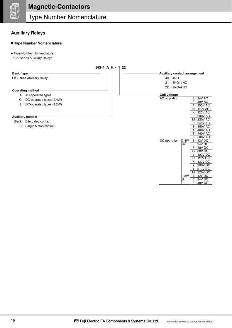
SK-Series Auxiliary Relays
SKH4 A H - 1 22
Basic typeSK-Series Auxiliary Relay
Operating methodA : AC-operated types
G : DC-operated types (2.4W)
L : DC-operated types (1.2W)
Auxiliary contact arrangement40 : 4NO
31 : 3NO+1NC
22 : 2NO+2NC
Auxiliary contactBlank : Bifurcated contact
H : Single button contact
Coil voltageAC operation E 24V AC
F 48V AC1 100V ACH 110V ACK 120V AC2 200V ACM 220V ACP 240V ACS 380V AC4 400V ACT 440V AC5 500V AC
DC operation 2.4W(G)
B 12V DCE 24V DCF 48V DCG 60V DC1 100V DCH 110V DCK 120V DC2 200V DCY 210V DCM 220V DC
1.2W(L)
B 12V DCE 24V DCF 48V DC
Auxiliary Relays
Type Number Nomenclature
1111
Magnetic-Contactors
Information subject to change without notice
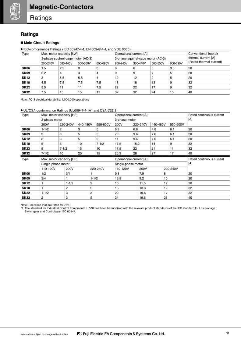
IEC-conformance Ratings (IEC 60947-4-1, EN 60947-4-1, and VDE 0660)Type Max. motor capacity [kW] Operational current [A] Conventional free air
thermal current [A](Rated thermal current)
3-phase squirrel-cage motor (AC-3) 3-phase squirrel-cage motor (AC-3)
200-240V 380-440V 500-550V 600-690V 200-240V 380-440V 500-550V 600-690V
SK06 1.5 2.2 3 3 6 6 5 3.5 20
SK09 2.2 4 4 4 9 9 7 5 20
SK12 3 5.5 5.5 4 12 12 9 5 20
SK18 4.5 7.5 7.5 7.5 18 18 13 9 32
SK22 5.5 11 11 7.5 22 22 17 9 32
SK32 7.5 15 15 11 32 32 24 15 40
Note: AC-3 electrical durability: 1,000,000 operations
UL/CSA-conformance Ratings (UL60947-4-1A*1 and CSA C22.2)Type Max. motor capacity [HP] Operational current [A] Rated continuous current
[A]3-phase motor 3-phase motor
200V 220-240V 440-480V 550-600V 200V 220-240V 440-480V 550-600V
SK06 1-1/2 2 3 5 6.9 6.8 4.8 6.1 20
SK09 2 3 5 5 7.8 9.6 7.6 6.1 20
SK12 3 3 5 5 11 9.6 7.6 6.1 20
SK18 5 5 10 7-1/2 17.5 15.2 14 9 32
SK22 5 7-1/2 15 10 17.5 22 21 11 32
SK32 7-1/2 10 20 15 25.3 28 27 17 40
Type Max. motor capacity [HP] Operational current [A] Rated continuous current[A]Single-phase motor Single-phase motor
110-120V 200V 220-240V 110-120V 200V 220-240V
SK06 1/2 3/4 1 9.8 7.9 8 20
SK09 3/4 1 1-1/2 13.8 9.2 10 20
SK12 1 1-1/2 2 16 11.5 12 20
SK18 1 2 2 16 13.8 12 32
SK22 1-1/2 3 3 20 19.6 17 32
SK32 2 3 5 24 19.6 28 40
Note: Use wires that are rated for 75°C.*1 The standard for Industrial Control Equipment UL 508 has been harmonized with the relevant product standards of the IEC standard for Low-Voltage
Switchgear and Controlgear IEC 60947.
Main Circuit Ratings
Ratings
Ratings

1212
Magnetic-Contactors
Information subject to change without notice
IEC-conformance Ratings (Standard Models: Bifurcated Contact)Type Conventional free air
thermal current [A](Rated thermal current)
Making and breaking current (AC)
Rated operational current [A] Minimum voltage and current
AC rated operational voltage [V]
AC-15 (Ind. load)
AC-12 (Res. load)
DC rated operational voltage [V]
DC-13 (Ind. load)
DC-12 (Res. load)
SK06SK09SK12SKH4
10 30 100-120 3 6 24 2 3 5V DC, 3mA
30 200-240 3 6 48 1 2
10 380-440 1 6 110 0.3 1.5
5 500-600 0.5 3 220 0.2 0.5
SK18SK22SK32
10 60 100-120 6 10 24 3 5 5V DC, 3mA
30 200-240 3 8 48 1.5 3
15 380-440 1.5 5 110 0.55 2.5
12 500-600 12 5 220 0.27 1
Note:Thefailurelevelis10-7foranormalenvironmentwithoutdust,dirt,orcorrosivegas. Theratingsofadditionalauxiliarycontactsarethesameasthosegivenabove.
IEC-conformance Ratings (Single Button Contact)Type Conventional free air
thermal current [A](Rated thermal current)
Making and breaking current (AC)
Rated operational current [A] Minimum voltage and current
AC rated operational voltage [V]
AC-15 (Ind. load)
AC-12 (Res. load)
DC rated operational voltage [V]
DC-13 (Ind. load)
DC-12 (Res. load)
SK06□HSK09□HSK12□HSKH4□H
10 60 100-120 6 10 24 4 8 24V DC, 10mA
60 200-240 6 10 48 1 3.5
60 380-440 6 10 110 0.5 2.5
30 500-600 3 5 220 0.25 0.8
SK18□HSK22□HSK32□H
10 60 100-120 6 10 24 5 10 24V DC, 10mA
60 200-240 6 10 48 1.5 5
40 380-440 4 10 110 0.7 4
40 500-600 4 10 220 0.27 1
Note:Thefailurelevelis10-7foranormalenvironmentwithoutdust,dirt,orcorrosivegas. Theratingsofadditionalauxiliarycontactsarethesameasthosegivenabove.
UL/CSA-conformance Ratings (Bifurcated Contact or Single Button Contact)Type Rated
continuous current [A]
Rated operational current [A] Rating code
AC DC
Rated operational voltage [V]
Making Breaking Rated operational voltage [V]
Making Breaking AC DC
SK06SK09SK12SK18SK22SK32SKH4
10 120 60 6 125 0.55 0.55 A600 Q300
240 30 3
480 15 1.5 250 0.27 0.27
600 12 1.2
Auxiliary Circuit Ratings
Ratings

1313
SK SeriesMagnetic-Contactors
Information subject to change without notice
AC-operated TypesType Order voltage Code Coil voltage and frequency
SK06ASK09ASK12ASK18ASK22ASK32A
24V AC E 24V 50Hz / 24-26V 60Hz
48V AC F 48V 50Hz / 48-52V 60Hz
100V AC 1 100V 50Hz / 100-110V 60Hz
110V AC H 100-110V 50Hz / 110-120V 60Hz
120V AC K 110-120V 50Hz / 120-130V 60Hz
200V AC 2 200V 50Hz / 200-220V 60Hz
220V AC M 200-220V 50Hz / 220-240V 60Hz
240V AC P 220-240V 50Hz / 240-260V 60Hz
380V AC S 346-380V 50Hz / 380-420V 60Hz
400V AC 4 380-400V 50Hz / 400-440V 60Hz
440V AC T 415-440V 50Hz / 440-480V 60Hz
500V AC 5 480-500V 50Hz / 500-550V 60Hz
DC-operated Types (2.4W)Type Order voltage Code Coil voltage
SK06GSK09GSK12GSK18GSK22GSK32G
12V DC B 12V DC
24V DC E 24V DC
48V DC F 48V DC
60V DC G 60V DC
100V DC 1 100V DC
110V DC H 110V DC
120V DC K 120V DC
200V DC 2 200V DC
210V DC Y 210V DC
220V DC M 220V DC
DC-operated Types (1.2W)Type Order voltage Code Coil voltage
SK06LSK09LSK12L
12V DC B 12V DC
24V DC E 24V DC
48V DC F 48V DC
Operating Coil Voltages

1414
Magnetic-Contactors
Information subject to change without notice
AC-operated TypesType Power consumption [VA] Watt loss [W] Pick-up voltage [V] Drop-out voltage
[V]Operating times [ms]
Inrush Sealed Coil ON → Contact ON
Coil OFF → Contact OFF200V
50Hz220V 60Hz
200V 50Hz
220V 60Hz
200V 50Hz
220V 60Hz
50Hz 60Hz 50Hz 60Hz
SK06ASK09ASK12A
22 25 4.5 4.5 1.2 1.3 122-135 128-138 80-89 83-96 17-26 8-11
SK18ASK22A
90 95 9 9 2.7 2.8 118-136 130-146 75-106 88-120 9-20 5-16
SK32A 90 95 9 9 2.7 2.8 118-136 130-146 75-106 88-120 9-20 5-16
Note 1. The characteristics are for the following coil ratings: 200V, 50Hz/200 to 220V, 60Hz.Note 2. The electromagnet capacity is the same even when the rated coil voltage is not 200V AC.Note 3. The operating times are for 200V AC, 50Hz.Note 4. The pick-up voltage and drop-out voltage for a 100V (100V AC, 50 Hz/100 to 110V, 60Hz) coil are approximately half of the values that are given in the above table.Note 5. The values in the above table are examples for a cold status at 20°C.
DC-operated Types (2.4W)Type Power consumption [W] Time constant
[ms]Pick-up voltage [V] Drop-out voltage
[V]Operating times [ms]
Inrush Sealed Sealed Coil ON → Contact ON
Coil OFF → Contact OFF24V 24V
SK06GSK09GSK12G
2.4 2.4 20 10-11 4-6 22-24 5-6
SK18GSK22G
2.4 2.4 33 15-16 3.5-5 65-72 18-23
SK32G 2.4 2.4 33 15-16 3.5-5 65-72 18-23
Note 1. The characteristics are for the following coil rating: 24V DC.Note 2. The electromagnet capacity is the same even when the rated coil voltage is not 24V DC.Note 3. The values in the above table are examples for a cold status at 20°C.Note 4. This operating time is based on a reference value and it is not a guaranteed operating time.
DC-operated Types (1.2W)Type Power consumption [W] Time constant
[ms]Pick-up voltage [V] Drop-out voltage
[V]Operating times [ms]
SK06LSK09LSK12L
Inrush Sealed Sealed Coil ON → Contact ON
Coil OFF → Contact OFF24V 24V
1.2 1.2 20 13-14 4-5 30-33 8-9
Note 1. The characteristics are for the following coil rating: 24V DC.Note 2. The electromagnet capacity is the same even when the rated coil voltage is not 24V DC.Note 3. The values in the above table are examples for a cold status at 20°C.Note 4. This operating time is based on a reference value and it is not a guaranteed operating time.
Operating Coil Characteristics
Ratings
1515
SK SeriesMagnetic-Contactors
Information subject to change without notice
SK06 to SK32
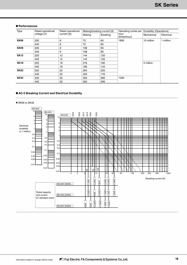
Type Rated operational voltage [V]
Rated operational current [A]
Making/breaking current [A] Operating cycles per hour [times/hour]
Durability (Operations)
Making Breaking Mechanical Electrical
SK06 220 6 72 60 1800 10 million 1 million
440 6 72 60
SK09 220 9 108 90
440 9 108 90
SK12 220 12 144 120
440 12 144 120
SK18 220 18 216 180 5 million
440 18 180 144
SK22 220 22 264 220
440 22 220 176
SK32 220 32 320 260 1200
440 32 320 256
Performances
AC-3 Breaking Current and Electrical Durability
200-240V 50/60Hz
380-440V 50/60Hz
500-550V 50/60Hz
0.01
0.1
0.02
0.03
0.05
1
0.2
0.3
0.5
10
2
3
5
2 3 20 30 50 100 200 300 500 1000
0.01
0.1
0.02
0.03
0.05
1
0.2
0.3
0.5
10
2
3
5
0.01
0.1
0.02
0.03
0.05
1
0.2
0.3
0.5
10
2
3
5
2.2k
W
9A
3kW
4.5k
W
5.5k
W
12A
1.5k
W
4kW
5.5k
W
7.5k
W
11kW
7.5k
W
15kW
2.2k
W
4kW
5.5k
W
9kW
15kW
7.5k
W
3kW
6A
105
200-240V SK
06
SK
09
SK
12
SK
18
SK
22
SK
32
500-550V
380-440V
Electrical durability (x 1 million)
Breaking current [A]
Rated capacity and current for standard motor
1616
Magnetic-Contactors
Information subject to change without notice
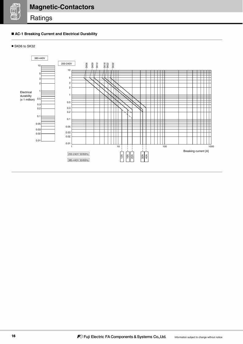
SK06 to SK32
AC-1 Breaking Current and Electrical Durability
1 10 100 1000
200-240V
0.1
380-440V
20 32AA
40A200-240V 50/60Hz
380-440V 50/60Hz
16A
12A
Breaking current [A]
Electrical durability (x 1 million)
0.01
0.1
0.02
0.03
0.05
1
0.2
0.3
0.5
10
2
3
5
0.01
0.1
0.02
0.03
0.05
1
0.2
0.3
0.5
10
2
3
5
SK
06
SK
09
SK
12
SK
18S
K22
SK
32
Ratings

1717
Magnetic-Contactors
Information subject to change without notice
Prospective Short-circuit Current “r” (240V and 440V)
Magnetic Contactor
Thermal Overload Relay Coordination typeType 1 Type 2
Type Type Ampere setting range [A]
Short-circuit current “r” [kA]
Molded Case Circuit Breaker /Earth Leakage Circuit Breaker
Short-circuit current “r” [kA]
Fuse(IEC 60269-1 gG and gM)rating (A)
FUJI Low-voltage Current-limiting Fuse
Type Rating [A] Type Rating [A]
SK06 TK12 0.34-0.52 1 BW32SAGEW32SAGBW32SBGEW32SBG
3 1 2 BLA003 30.48-0.72 1 3 1 4 BLA005 50.64-0.96 1 5 1 4 BLA005 50.8-1.2 1 5 1 4 BLA005 50.95-1.45 1 10 1 16 BLA020 201.1-1.65 1 10 1 16 BLA020 201.4-2.1 1 20 1 16 BLA020 201.7-2.6 1 20 1 16 BLA020 202.2-3.4 1 20 1 16 BLA020 202.8-4.2 1 20 1 16 BLA020 204-6 1 20 1 16 BLA020 20
SK09 TK12 0.34-0.52 1 BW32SAGEW32SAGBW32SBGEW32SBG
3 1 2 BLA003 30.48-0.72 1 3 1 4 BLA005 50.64-0.96 1 5 1 4 BLA005 50.8-1.2 1 5 1 4 BLA005 50.95-1.45 1 10 1 16 BLA020 201.1-1.65 1 10 1 16 BLA020 201.4-2.1 1 20 1 16 BLA020 201.7-2.6 1 20 1 16 BLA020 202.2-3.4 1 20 1 16 BLA020 202.8-4.2 1 20 1 16 BLA020 204-6 1 20 1 16 BLA020 205-7.5 1 20 1 16 BLA020 206-9 1 20 1 16 BLA020 20
SK12 TK12 0.34-0.52 1 BW32SAGEW32SAGBW32SBGEW32SBG
3 1 2 BLA003 30.48-0.72 1 3 1 4 BLA005 50.64-0.96 1 5 1 4 BLA005 50.8-1.2 1 5 1 4 BLA005 50.95-1.45 1 10 1 16 BLA020 201.1-1.65 1 10 1 16 BLA020 201.4-2.1 1 20 1 16 BLA020 201.7-2.6 1 20 1 16 BLA020 202.2-3.4 1 20 1 16 BLA020 202.8-4.2 1 20 1 16 BLA020 204-6 1 20 1 16 BLA020 205-7.5 1 20 1 16 BLA020 206-9 1 20 1 16 BLA020 207-10.5 1 20 1 16 BLA020 209-13 1 30 1 16 BLA020 20
SK06 – 1 BW32SAGEW32SAGBW32SBGEW32SBG
30 1 16 BLA020 20SK09 – 1 1 16 BLA020 20SK12 – 1 1 16 BLA020 20
Coordination with Short-circuit Protection Devices (SCPD) (Based on IEC Standards)
Protective Coordination

1818
Magnetic-Contactors
Information subject to change without notice
Prospective Short-circuit Current “r” (240V and 440V)
Magnetic Contactor
Thermal Overload Relay Coordination typeType 1 Type 2
Type Type Ampere setting range [A]
Short-circuit current “r” [kA]
Molded Case Circuit Breaker /Earth Leakage Circuit Breaker
Short-circuit current “r” [kA]
Fuse(IEC 60269-1 gG and gM)rating (A)
FUJI Low-voltage Current-limiting Fuse
Type Rating [A] Type Rating [A]
SK18 TK25 0.34-0.52 3 BW50SAGEW50SAGBW50SBGEW50SBG
3 3 2 BLA003 30.48-0.72 3 3 3 4 BLA005 50.64-0.96 3 5 3 4 BLA005 50.8-1.2 3 5 3 16 BLA020 200.95-1.45 3 10 3 20 BLA030 301.1-1.65 3 10 3 20 BLA030 301.4-2.1 3 20 3 20 BLA030 301.7-2.6 3 20 3 20 BLA030 302.2-3.4 3 20 3 20 BLA030 302.8-4.2 3 20 3 20 BLA030 304-6 3 20 3 20 BLA030 305-7.5 3 20 3 20 BLA030 306-9 3 20 3 20 BLA030 307-10.5 3 20 3 25 BLA040 409-13 3 30 3 25 BLA040 4012-18 3 30 3 40 BLA060 60
SK22 TK25 0.34-0.52 3 BW50SAGEW50SAGBW50SBGEW50SBG
3 3 2 BLA003 30.48-0.72 3 3 3 4 BLA005 50.64-0.96 3 5 3 4 BLA005 50.8-1.2 3 5 3 16 BLA020 200.95-1.45 3 10 3 20 BLA030 301.1-1.65 3 10 3 20 BLA030 301.4-2.1 3 20 3 20 BLA030 301.7-2.6 3 20 3 20 BLA030 302.2-3.4 3 20 3 20 BLA030 302.8-4.2 3 20 3 20 BLA030 304-6 3 20 3 20 BLA030 305-7.5 3 20 3 20 BLA030 306-9 3 20 3 20 BLA030 307-10.5 3 20 3 25 BLA040 409-13 3 30 3 25 BLA040 4012-18 3 30 3 40 BLA060 6016-22 3 50 3 50 BLA075 75
SK32 TK26 0.34-0.52 3 BW50SAGEW50SAGBW50SBGEW50SBG
3 3 2 BLA003 30.48-0.72 3 3 3 4 BLA005 50.64-0.96 3 5 3 4 BLA005 50.8-1.2 3 5 3 16 BLA020 200.95-1.45 3 10 3 20 BLA030 301.1-1.65 3 10 3 20 BLA030 301.4-2.1 3 20 3 20 BLA030 301.7-2.6 3 20 3 20 BLA030 302.2-3.4 3 20 3 20 BLA030 302.8-4.2 3 20 3 20 BLA030 304-6 3 20 3 20 BLA030 305-7.5 3 20 3 20 BLA030 306-9 3 20 3 20 BLA030 307-10.5 3 20 3 25 BLA040 409-13 3 30 3 25 BLA040 4012-18 3 30 3 40 BLA060 6016-22 3 50 3 50 BLA075 7520-26 3 50 3 50 BLA075 7526-32 3 BW63SAG
EW63SAGBW63SBGEW63SBG
63 3 50 BLA075 75
SK18 – – 3 BW50SAGEW50SAGBW50SBGEW50SBG
50 3 50 BLA075 75SK22 – – 3 3 50 BLA075 75
SK32 – – 3 BW63SAGEW63SAGBW63SBGEW63SBG
63 3 50 BLA075 75
Protective Coordination

1919
SK SeriesMagnetic-Contactors
Information subject to change without notice
Rated conditional short-circuit current Iq (240V)
Magnetic Contactor
Thermal Overload Relay Coordination typeType 1 Type 2
Type Type Ampere setting range [A]
Short-circuit current “Iq” [kA]
Molded Case Circuit Breaker /Earth Leakage Circuit Breaker
Short-circuit current “Iq” [kA]
Fuse(IEC 60269-1 gG and gM)rating (A)
FUJI Low-voltage Current-limiting Fuse
Type Rating [A] Type Rating [A]
SK06 TK12 0.34-0.52 25 BW50RAGEW50RAG
3 50 2 BLA003 30.48-0.72 25 3 50 4 BLA005 50.64-0.96 25 5 50 4 BLA005 50.8-1.2 25 5 50 4 BLA005 50.95-1.45 25 10 50 16 BLA020 201.1-1.65 25 10 50 16 BLA020 201.4-2.1 25 10 50 20 BLA030 301.7-2.6 25 10 50 20 BLA030 302.2-3.4 25 10 50 20 BLA030 302.8-4.2 25 10 50 20 BLA030 304-6 25 10 50 20 BLA030 30
SK09 TK12 0.34-0.52 25 BW50RAGEW50RAG
3 50 2 BLA003 30.48-0.72 25 3 50 4 BLA005 50.64-0.96 25 5 50 4 BLA005 50.8-1.2 25 5 50 4 BLA005 50.95-1.45 25 10 50 16 BLA020 201.1-1.65 25 10 50 16 BLA020 201.4-2.1 25 10 50 20 BLA030 301.7-2.6 25 10 50 20 BLA030 302.2-3.4 25 10 50 20 BLA030 302.8-4.2 25 10 50 20 BLA030 304-6 25 10 50 20 BLA030 305-7.5 25 30 50 20 BLA030 306-9 25 30 50 20 BLA030 30
SK12 TK12 0.34-0.52 25 BW50RAGEW50RAG
3 50 2 BLA003 30.48-0.72 25 3 50 4 BLA005 50.64-0.96 25 5 50 4 BLA005 50.8-1.2 25 5 50 4 BLA005 50.95-1.45 25 10 50 16 BLA020 201.1-1.65 25 10 50 16 BLA020 201.4-2.1 25 10 50 20 BLA030 301.7-2.6 25 10 50 20 BLA030 302.2-3.4 25 10 50 20 BLA030 302.8-4.2 25 10 50 20 BLA030 304-6 25 10 50 20 BLA030 305-7.5 25 30 50 20 BLA030 306-9 25 30 50 20 BLA030 307-10.5 25 30 50 20 BLA030 309-13 25 30 50 20 BLA030 30
SK06 – – 25 BW50RAGEW50RAG
30 50 20 BLA030 30SK09 – – 25 50 20 BLA030 30SK12 – – 25 50 20 BLA030 30

2020
Magnetic-Contactors
Information subject to change without notice
Rated conditional short-circuit current Iq (240V)
Magnetic Contactor
Thermal Overload Relay Coordination typeType 1 Type 2
Type Type Ampere setting range [A]
Short-circuit current “Iq” [kA]
Molded Case Circuit Breaker /Earth Leakage Circuit Breaker
Short-circuit current “Iq” [kA]
Fuse(IEC 60269-1 gG and gM)rating (A)
FUJI Low-voltage Current-limiting Fuse
Type Rating [A] Type Rating [A]
SK18 TK25 0.34-0.52 10 BW50RAGEW50RAG
3 50 2 BLA003 30.48-0.72 10 3 50 4 BLA005 50.64-0.96 10 5 50 4 BLA005 50.8-1.2 10 5 50 4 BLA005 50.95-1.45 10 10 50 16 BLA020 201.1-1.65 10 10 50 16 BLA020 201.4-2.1 10 10 50 20 BLA030 301.7-2.6 10 10 50 20 BLA030 302.2-3.4 10 10 50 20 BLA030 302.8-4.2 10 10 50 20 BLA030 304-6 10 10 50 20 BLA030 305-7.5 10 30 50 20 BLA030 306-9 10 30 50 20 BLA030 307-10.5 10 30 50 20 BLA030 309-13 10 30 50 25 BLA040 4012-18 10 30 50 25 BLA040 40
SK22 TK25 0.34-0.52 10 3 50 2 BLA003 30.48-0.72 10 3 50 4 BLA005 50.64-0.96 10 5 50 4 BLA005 50.8-1.2 10 5 50 4 BLA005 50.95-1.45 10 10 50 16 BLA020 201.1-1.65 10 10 50 16 BLA020 201.4-2.1 10 10 50 20 BLA030 301.7-2.6 10 10 50 20 BLA030 302.2-3.4 10 10 50 20 BLA030 302.8-4.2 10 10 50 20 BLA030 304-6 10 10 50 20 BLA030 305-7.5 10 30 50 20 BLA030 306-9 10 30 50 20 BLA030 307-10.5 10 30 50 20 BLA030 309-13 10 30 50 25 BLA040 4012-18 10 30 50 25 BLA040 4016-22 10 50 50 25 BLA040 40
SK32 TK26 0.34-0.52 10 3 50 2 BLA003 30.48-0.72 10 3 50 4 BLA005 50.64-0.96 10 5 50 4 BLA005 50.8-1.2 10 5 50 4 BLA005 50.95-1.45 10 10 50 16 BLA020 201.1-1.65 10 10 50 16 BLA020 201.4-2.1 10 10 50 20 BLA030 301.7-2.6 10 10 50 20 BLA030 302.2-3.4 10 10 50 20 BLA030 302.8-4.2 10 10 50 20 BLA030 304-6 10 10 50 20 BLA030 305-7.5 10 30 50 20 BLA030 306-9 10 30 50 20 BLA030 307-10.5 10 30 50 20 BLA030 309-13 10 30 50 25 BLA040 4012-18 10 30 50 25 BLA040 4016-22 10 50 50 40 BLA060 6020-26 10 50 50 50 BLA060 6026-32 10 BW63RAG
EW63RAG63 50 50 BLA060 60
SK18 − − 10 BW50RAGEW50RAG
50 50 25 BLA040 40SK22 − − 10 50 25 BLA040 40SK32 − − 10 BW63RAG
EW63RAG63 50 50 BLA075 75
Protective Coordination

2121
SK SeriesMagnetic-Contactors
Information subject to change without notice
Combination of Breaker and Fuse (UL60947-4-1 Type C)Magnetic Starter Short-circuit Current Ratings (SCCR)Magnetic Contactor
Thermal Overload Relay
240V AC 240V AC 600V AC
Type Type Ampere setting range [A]
SCCR[kA]
Circuit breaker SCCR[kA]
Circuit breaker SCCR[kA]
Circuit breaker
Current-limiting fuse
Max. rated current [A]
UL489-certified Molded Case Circuit Breaker /Earth Leakage Circuit Breaker
Max. rated current [A]
UL489-certified Molded Case Circuit Breaker /Earth Leakage Circuit Breaker
Max. rated current [A]
Max. rated current [A]
SK06 TK12 0.1-0.15 18 15 BW50RBGUEW50RBGU
25 15 BW125JAGUBW125RAGUEW125JAGUEW125RAGU
5 − 300.13-0.2 18 15 25 15 5 − 300.18-0.27 18 15 25 15 5 − 300.24-0.36 18 15 25 15 5 − 300.3-0.45 18 15 25 15 5 − 300.34-0.52 18 15 25 15 5 − 300.48-0.72 18 15 25 15 5 − 300.64-0.96 18 15 25 15 5 − 300.8-1.2 18 15 25 15 5 − 300.95-1.45 18 20 25 15 5 − 301.1-1.65 18 20 25 15 5 − 301.4-2.1 18 20 25 20 5 − 301.7-2.6 18 20 25 20 5 − 302.2-3.4 18 20 25 20 5 − 302.8-4.2 18 20 25 20 5 − 304-6 18 20 25 20 5 − 30
SK09 TK12 0.1-0.15 18 15 BW50RBGUEW50RBGU
25 15 BW125JAGUBW125RAGUEW125JAGUEW125RAGU
5 − 300.13-0.2 18 15 25 15 5 − 300.18-0.27 18 15 25 15 5 − 300.24-0.36 18 15 25 15 5 − 300.3-0.45 18 15 25 15 5 − 300.34-0.52 18 15 25 15 5 − 300.48-0.72 18 15 25 15 5 − 300.64-0.96 18 15 25 15 5 − 300.8-1.2 18 15 25 15 5 − 300.95-1.45 18 20 25 15 5 − 301.1-1.65 18 20 25 15 5 − 301.4-2.1 18 20 25 20 5 − 301.7-2.6 18 20 25 20 5 − 302.2-3.4 18 20 25 20 5 − 302.8-4.2 18 20 25 20 5 − 304-6 18 20 25 20 5 − 305-7.5 18 20 25 20 5 − 306-9 18 20 25 20 5 − 30
SK12 TK12 0.1-0.15 18 15 BW50RBGUEW50RBGU
25 15 BW125JAGUBW125RAGUEW125JAGUEW125RAGU
5 − 300.13-0.2 18 15 25 15 5 − 300.18-0.27 18 15 25 15 5 − 300.24-0.36 18 15 25 15 5 − 300.3-0.45 18 15 25 15 5 − 300.34-0.52 18 15 25 15 5 − 300.48-0.72 18 15 25 15 5 − 300.64-0.96 18 15 25 15 5 − 300.8-1.2 18 15 25 15 5 − 300.95-1.45 18 20 25 15 5 − 301.1-1.65 18 20 25 15 5 − 301.4-2.1 18 20 25 20 5 − 301.7-2.6 18 20 25 20 5 − 302.2-3.4 18 20 25 20 5 − 302.8-4.2 18 20 25 20 5 − 304-6 18 20 25 20 5 − 305-7.5 18 20 25 20 5 − 306-9 18 20 25 20 5 − 307-10.5 18 20 25 20 5 − 309-13 18 30 25 30 5 − 30
SK06 − − 18 30 BW50RBGUEW50RBGU
25 30 BW125JAGUBW125RAGUEW125JAGUEW125RAGU
5 − 30SK09 − − 18 30 25 30 5 − 30SK12 − − 18 30 25 30 5 − 30
UL approved Short-circuit Current Ratings (SCCR)

2222
Magnetic-Contactors
Information subject to change without notice
Combination of Breaker and Fuse (UL60947-4-1 Type C) (Continued)Magnetic Starter Short-circuit Current Ratings (SCCR)Magnetic Contactor
Thermal Overload Relay
240V AC 480V AC 600V AC
Type Type Ampere setting range [A]
SCCR[kA]
Circuit breaker SCCR[kA]
Circuit breaker SCCR[kA]
Circuit breaker
Current-limiting fuse
Max. rated current [A]
UL489-certified Molded Case Circuit Breaker /Earth Leakage Circuit Breaker
Max. rated current [A]
UL489-certified Molded Case Circuit Breaker /Earth Leakage Circuit Breaker
Max. rated current [A]
Max. rated current [A]
SK18 TK25 0.1-0.15 35 15 BW125JAGUEW125JAGU
35 15 BW125RAGUEW125RAGU
5 − 300.13-0.2 35 15 35 15 5 − 300.18-0.27 35 15 35 15 5 − 300.24-0.36 35 15 35 15 5 − 300.34-0.52 35 15 35 15 5 − 300.48-0.72 35 15 35 15 5 − 300.64-0.96 35 15 35 15 5 − 300.8-1.2 35 15 35 15 5 − 300.95-1.45 35 15 35 15 5 − 301.1-1.65 35 15 35 15 5 − 301.4-2.1 35 20 35 20 5 − 301.7-2.6 35 20 35 20 5 − 302.2-3.4 35 20 35 20 5 − 302.8-4.2 35 20 35 20 5 − 304-6 35 20 35 20 5 − 305-7.5 35 20 35 20 5 − 306-9 35 20 35 20 5 − 307-10.5 35 20 35 20 5 − 309-13 35 30 35 30 5 − 3012-18 35 30 35 30 5 − 50
25 40 10 40SK22 TK25 0.1-0.15 35 15 BW125JAGU
EW125JAGU35 15 BW125RAGU
EW125RAGU5 − 30
0.13-0.2 35 15 35 15 5 − 300.18-0.27 35 15 35 15 5 − 300.24-0.36 35 15 35 15 5 − 300.34-0.52 35 15 35 15 5 − 300.48-0.72 35 15 35 15 5 − 300.64-0.96 35 15 35 15 5 − 300.8-1.2 35 15 35 15 5 − 300.95-1.45 35 15 35 15 5 − 301.1-1.65 35 15 35 15 5 − 301.4-2.1 35 20 35 20 5 − 301.7-2.6 35 20 35 20 5 − 302.2-3.4 35 20 35 20 5 − 302.8-4.2 35 20 35 20 5 − 304-6 35 20 35 20 5 − 305-7.5 35 20 35 20 5 − 306-9 35 20 35 20 5 − 307-10.5 35 20 35 20 5 − 309-13 35 30 35 30 5 − 3012-18 35 30 35 30 5 − 50
25 40 10 40 BW125JAGUEW125JAGU
16-22 35 30 35 30 BW125RAGUEW125RAGU
5 − 50
25 50 10 50 BW125JAGUEW125JAGU
Protective Coordination

2323
SK SeriesMagnetic-Contactors
Information subject to change without notice
Combination of Breaker and Fuse (UL60947-4-1 Type C) (Continued)Magnetic Starter Short-circuit Current Ratings (SCCR)Magnetic Contactor
Thermal Overload Relay
240V AC 480V AC 600V AC
Type Type Ampere setting range [A]
SCCR[kA]
Circuit breaker SCCR[kA]
Circuit breaker SCCR[kA]
Circuit breaker
Current-limiting fuse
Max. rated current [A]
UL489-certified Molded Case Circuit Breaker /Earth Leakage Circuit Breaker
Max. rated current [A]
UL489-certified Molded Case Circuit Breaker /Earth Leakage Circuit Breaker
Max. rated current [A]
Max. rated current [A]
SK32 TK26 0.1-0.15 35 15 BW125JAGUEW125JAGU
35 15 BW125RAGUEW125RAGU
5 − 300.13-0.2 35 15 35 15 5 − 300.18-0.27 35 15 35 15 5 − 300.24-0.36 35 15 35 15 5 − 300.34-0.52 35 15 35 15 5 − 300.48-0.72 35 15 35 15 5 − 300.64-0.96 35 15 35 15 5 − 300.8-1.2 35 15 35 15 5 − 300.95-1.45 35 15 35 15 5 − 301.1-1.65 35 15 35 15 5 − 301.4-2.1 35 20 35 20 5 − 301.7-2.6 35 20 35 20 5 − 302.2-3.4 35 20 35 20 5 − 302.8-4.2 35 20 35 20 5 − 304-6 35 20 35 20 5 − 305-7.5 35 20 35 20 5 − 306-9 35 20 35 20 5 − 307-10.5 35 20 35 20 5 − 309-13 35 30 35 30 5 − 3012-18 35 30 35 30 5 − 50
25 40 10 4016-22 35 30 35 30 5 − 50
25 50 10 5020-26 35 30 35 30 5 − 50
25 50 10 50 BW125JAGUEW125JAGU
26-32 35 30 35 30 BW125RAGUEW125RAGU
5 − 50
25 50 10 60 BW125JAGUEW125JAGU
SK18 − − 35 30 BW125JAGUEW125JAGU
35 30 BW125RAGUEW125RAGU
5 50 50
25 50 10 50 BW125JAGUEW125JAGU
SK22 − − 35 30 35 30 BW125RAGUEW125RAGU
5 50 50
25 50 10 50 BW125JAGUEW125JAGU
SK32 − − 35 30 BW125JAGUEW125JAGU
35 30 BW125RAGUEW125RAGU
5 70 70
− 25 60 10 60 BW125JAGUEW125JAGU
2424
Magnetic-Contactors
Information subject to change without notice
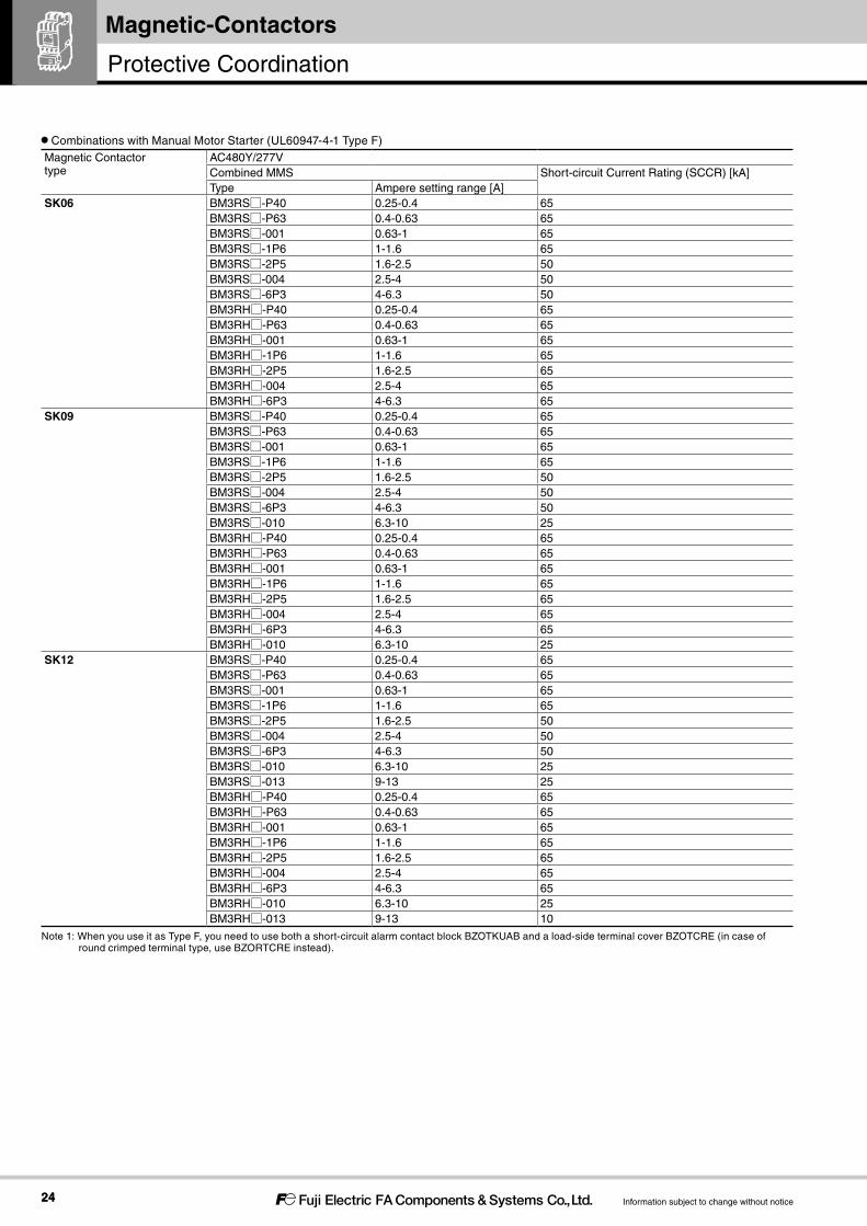
Combinations with Manual Motor Starter (UL60947-4-1 Type F)
Magnetic Contactortype
AC480Y/277VCombined MMS Short-circuit Current Rating (SCCR) [kA]Type Ampere setting range [A]
SK06 BM3RS□-P40 0.25-0.4 65BM3RS□-P63 0.4-0.63 65BM3RS□-001 0.63-1 65BM3RS□-1P6 1-1.6 65BM3RS□-2P5 1.6-2.5 50BM3RS□-004 2.5-4 50BM3RS□-6P3 4-6.3 50BM3RH□-P40 0.25-0.4 65BM3RH□-P63 0.4-0.63 65BM3RH□-001 0.63-1 65BM3RH□-1P6 1-1.6 65BM3RH□-2P5 1.6-2.5 65BM3RH□-004 2.5-4 65BM3RH□-6P3 4-6.3 65
SK09 BM3RS□-P40 0.25-0.4 65BM3RS□-P63 0.4-0.63 65BM3RS□-001 0.63-1 65BM3RS□-1P6 1-1.6 65BM3RS□-2P5 1.6-2.5 50BM3RS□-004 2.5-4 50BM3RS□-6P3 4-6.3 50BM3RS□-010 6.3-10 25BM3RH□-P40 0.25-0.4 65BM3RH□-P63 0.4-0.63 65BM3RH□-001 0.63-1 65BM3RH□-1P6 1-1.6 65BM3RH□-2P5 1.6-2.5 65BM3RH□-004 2.5-4 65BM3RH□-6P3 4-6.3 65BM3RH□-010 6.3-10 25
SK12 BM3RS□-P40 0.25-0.4 65BM3RS□-P63 0.4-0.63 65BM3RS□-001 0.63-1 65BM3RS□-1P6 1-1.6 65BM3RS□-2P5 1.6-2.5 50BM3RS□-004 2.5-4 50BM3RS□-6P3 4-6.3 50BM3RS□-010 6.3-10 25BM3RS□-013 9-13 25BM3RH□-P40 0.25-0.4 65BM3RH□-P63 0.4-0.63 65BM3RH□-001 0.63-1 65BM3RH□-1P6 1-1.6 65BM3RH□-2P5 1.6-2.5 65BM3RH□-004 2.5-4 65BM3RH□-6P3 4-6.3 65BM3RH□-010 6.3-10 25BM3RH□-013 9-13 10
Note 1: When you use it as Type F, you need to use both a short-circuit alarm contact block BZOTKUAB and a load-side terminal cover BZOTCRE (in case of round crimped terminal type, use BZORTCRE instead).
Protective Coordination

2525
SK SeriesMagnetic-Contactors
Information subject to change without notice
Magnetic Contactortype
AC480Y/277VCombined MMS Short-circuit Current Rating (SCCR) [kA]Type Ampere setting range [A]
SK18 BM3RS□-P40 0.25-0.4 65BM3RS□-P63 0.4-0.63 65BM3RS□-001 0.63-1 65BM3RS□-1P6 1-1.6 65BM3RS□-2P5 1.6-2.5 65BM3RS□-004 2.5-4 65BM3RS□-6P3 4-6.3 65BM3RS□-010 6.3-10 25BM3RS□-013 9-13 25BM3RS□-016 11-16 25BM3RS□-020 14-20 25BM3RH□-P40 0.25-0.4 65BM3RH□-P63 0.4-0.63 65BM3RH□-001 0.63-1 65BM3RH□-1P6 1-1.6 65BM3RH□-2P5 1.6-2.5 65BM3RH□-004 2.5-4 65BM3RH□-6P3 4-6.3 65BM3RH□-010 6.3-10 65BM3RH□-013 9-13 65BM3RH□-016 11-16 65BM3RH□-020 14-20 65
SK22 BM3RS□-P40 0.25-0.4 65BM3RS□-P63 0.4-0.63 65BM3RS□-001 0.63-1 65BM3RS□-1P6 1-1.6 65BM3RS□-2P5 1.6-2.5 65BM3RS□-004 2.5-4 65BM3RS□-6P3 4-6.3 65BM3RS□-010 6.3-10 25BM3RS□-013 9-13 25BM3RS□-016 11-16 25BM3RS□-020 14-20 25BM3RS□-025 19-25 25BM3RH□-P40 0.25-0.4 65BM3RH□-P63 0.4-0.63 65BM3RH□-001 0.63-1 65BM3RH□-1P6 1-1.6 65BM3RH□-2P5 1.6-2.5 65BM3RH□-004 2.5-4 65BM3RH□-6P3 4-6.3 65BM3RH□-010 6.3-10 65BM3RH□-013 9-13 65BM3RH□-016 11-16 65BM3RH□-020 14-20 65BM3RH□-025 19-25 50

2626
Magnetic-Contactors
Information subject to change without notice
Protective Coordination
Magnetic Contactortype
AC480Y/277VCombined MMS Short-circuit Current Rating (SCCR) [kA]Type Ampere setting range [A]
SK32 BM3RS□-P40 0.25-0.4 65BM3RS□-P63 0.4-0.63 65BM3RS□-001 0.63-1 65BM3RS□-1P6 1-1.6 65BM3RS□-2P5 1.6-2.5 65BM3RS□-004 2.5-4 65BM3RS□-6P3 4-6.3 65BM3RS□-010 6.3-10 25BM3RS□-013 9-13 25BM3RS□-016 11-16 25BM3RS□-020 14-20 25BM3RS□-025 19-25 25BM3RS□-032 24-32 25BM3RH□-P40 0.25-0.4 65BM3RH□-P63 0.4-0.63 65BM3RH□-001 0.63-1 65BM3RH□-1P6 1-1.6 65BM3RH□-2P5 1.6-2.5 65BM3RH□-004 2.5-4 65BM3RH□-6P3 4-6.3 65BM3RH□-010 6.3-10 65BM3RH□-013 9-13 65BM3RH□-016 11-16 65BM3RH□-020 14-20 65BM3RH□-025 19-25 50BM3RH□-032 24-32 50

2727
SK SeriesMagnetic-Contactors
Information subject to change without notice
b
CurrentT
ime
Motor current
MCCB/ELCB operating curve
Starting current increase
Thermal overload relay operating characteristics
Electric motor thermal characteristics
Applications for IE3 (premium efficiency) motors
IE3 (premium efficiency) motors have a 15 to 30% larger starting current
compared with conventional motors.
(There are cases they may require a longer starting time.)
Selecting magnetic contactors
If the starting current is increased, the make/break durability of
magnetic contactors is affected.
The life expectancy of magnetic contactors used in motors (AC-3 rating)
is based on a starting current that is six times the rated current. If a
starting current becomes larger than this (especially if it exceeds ten
times the rated value), the make/break durability could be significantly
reduced, or contact welding could occur. For this reason, be sure to
confirm the motor's starting current and the rating of the magnetic
contactor.
[What to do for a large starting current]
Choose a product while making sure that the starting current does not
exceed 10 times that of the rating (AC-3) of the magnetic contactor.
There are cases where the motor's rated current could increase. In
this case, choose a product while making sure it is within the range of
the magnetic contactor's AC-3 rating.
Selecting thermal relays
A larger starting current could cause it to enter the operating range of
the thermal overload relay, resulting in unnecessary operation (area
b in the diagram).
Therefore, be sure to confirm this matter for IE3 motor applications.
[What to do for a large starting current]
Measure 1: Raise the pick-up current value for the dial reading of the
thermal overload relay to around within 5%.
Measure 2: Use a time delay thermal overload relay (class 20 or
class 30).
Note 1: For Measures 1 and 2, confirm compatibility with the thermal characteristics of the electric motor.
Note 2: If the motor's rated current also increases, configure the thermal overload relay setting in accordance with the motor's rated current.
2828
Magnetic-Contactors
Information subject to change without notice
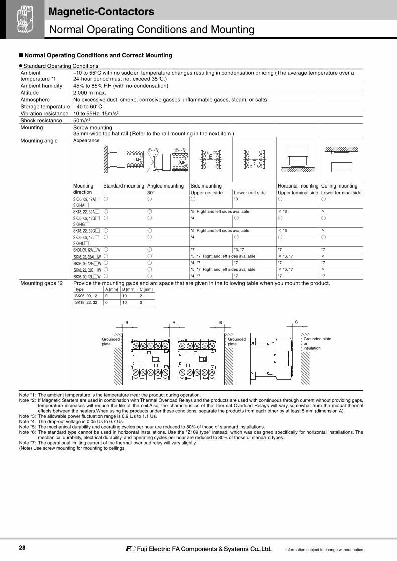
Standard Operating ConditionsAmbient temperature *1
−10 to 55°C with no sudden temperature changes resulting in condensation or icing (The average temperature over a 24-hour period must not exceed 35°C.)
Ambient humidity 45% to 85% RH (with no condensation)Altitude 2,000 m max.Atmosphere No excessive dust, smoke, corrosive gasses, inflammable gases, steam, or saltsStorage temperature −40 to 60°CVibration resistance 10 to 55Hz, 15m/s2
Shock resistance 50m/s2
Mounting Screw mounting35mm-wide top hat rail (Refer to the rail mounting in the next item.)
Mounting angle Appearance
A2
A1
A2
A1
30° 30°30° 30°
A2A1
A2 A1
Mounting direction
Standard mounting Angled mounting Side mounting Horizontal mounting Ceiling mounting− 30° Upper coil side Lower coil side Upper terminal side Lower terminal side
SK06, 09, 12A□SKH4A□
○ ○ ○ *3 ○ ○
SK18, 22, 32A□ ○ ○ *5 Right and left sides available × *6 ×
SK06, 09, 12G□SKH4G□
○ ○ *4 ○ ○ ○
SK18, 22, 32G□ ○ ○ *5 Right and left sides available × *6 ×
SK06, 09, 12L□SKH4L□
○ ○ *4 ○ ○ ○
SK06, 09, 12A□W ○ ○ *7 *3, *7 *7 *7
SK18, 22, 32A□W ○ ○ *5, *7 Right and left sides available × *6, *7 ×
SK06, 09, 12G□W ○ ○ *4, *7 *7 *7 *7
SK18, 22, 32G□W ○ ○ *5, *7 Right and left sides available × *6, *7 ×
SK06, 09, 12L□W ○ ○ *4, *7 *7 *7 *7
Mounting gaps *2 Provide the mounting gaps and arc space that are given in the following table when you mount the product.Type A [mm] B [mm] C [mm]
SK06, 09, 12 0 10 2
SK18, 22, 32 0 10 0
CBAB
Groundedplate
Groundedplate
Grounded plateorinsulation
Note *1: The ambient temperature is the temperature near the product during operation.Note *2: If Magnetic Starters are used in combination with Thermal Overload Relays and the products are used with continuous through current without providing gaps,
temperature increases will reduce the life of the coil.Also, the characteristics of the Thermal Overload Relays will vary somewhat from the mutual thermal effects between the heaters.When using the products under these conditions, separate the products from each other by at least 5 mm (dimension A).
Note *3: The allowable power fluctuation range is 0.9 Us to 1.1 Us.Note *4: The drop-out voltage is 0.05 Us to 0.7 Us.Note *5: The mechanical durability and operating cycles per hour are reduced to 80% of those of standard installations.Note *6: The standard type cannot be used in horizontal installations. Use the "Z109 type" instead, which was designed specifically for horizontal installations. The
mechanical durability, electrical durability, and operating cycles per hour are reduced to 80% of those of standard types.Note *7: The operational limiting current of the thermal overload relay will vary slightly.(Note) Use screw mounting for mounting to ceilings.
Normal Operating Conditions and Correct Mounting
Normal Operating Conditions and Mounting
2929
SK SeriesMagnetic-Contactors
Information subject to change without notice
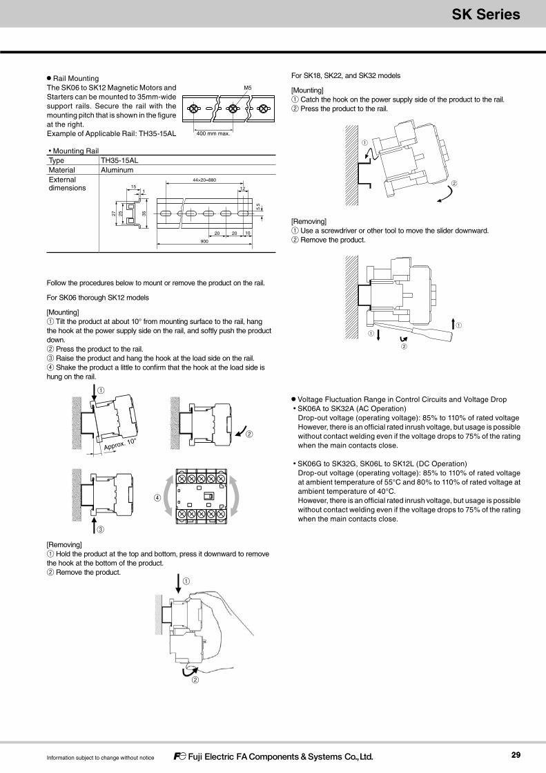
Mounting RailType TH35-15ALMaterial AluminumExternal dimensions
27
900
35
151
1020
44×20=880
12
5.5
20
25
Rail MountingThe SK06 to SK12 Magnetic Motors and Starters can be mounted to 35mm-wide support rails. Secure the rail with the mounting pitch that is shown in the figure at the right.Example of Applicable Rail: TH35-15AL
Follow the procedures below to mount or remove the product on the rail.
For SK06 thorough SK12 models
[Mounting] ① Tilt the product at about 10° from mounting surface to the rail, hang the hook at the power supply side on the rail, and softly push the product down. ② Press the product to the rail. ③ Raise the product and hang the hook at the load side on the rail. ④ Shake the product a little to confirm that the hook at the load side is hung on the rail.
For SK18, SK22, and SK32 models
[Mounting] ① Catch the hook on the power supply side of the product to the rail.② Press the product to the rail.
[Removing] ① Use a screwdriver or other tool to move the slider downward.② Remove the product.
[Removing] ① Hold the product at the top and bottom, press it downward to remove the hook at the bottom of the product. ② Remove the product.
Voltage Fluctuation Range in Control Circuits and Voltage Drop SK06A to SK32A (AC Operation)
Drop-out voltage (operating voltage): 85% to 110% of rated voltageHowever, there is an official rated inrush voltage, but usage is possible without contact welding even if the voltage drops to 75% of the rating when the main contacts close.
SK06G to SK32G, SK06L to SK12L (DC Operation)Drop-out voltage (operating voltage): 85% to 110% of rated voltage at ambient temperature of 55°C and 80% to 110% of rated voltage at ambient temperature of 40°C.However, there is an official rated inrush voltage, but usage is possible without contact welding even if the voltage drops to 75% of the rating when the main contacts close.
M5
400 mm max.
①
②
①
②
①①
②
Approx. 10°
③
④
②
①

3030
Magnetic-Contactors
Information subject to change without notice
Wiring and Terminal ProcessingMake all connections correctly according to the connection diagram. For the SK06 to SK32, you can use solid wires, stranded wires, or crimped terminals for the main terminals, auxiliary terminals, and coil terminals.
Tightening TorqueIf the Magnetic Contactor or Switch is not mounted completely, the shock when the Contactor or Switches is turned ON may cause the contacts to jump or may reduce the durability. Also, if wires are not tightened sufficiently, they may become hot or loose, resulting in a fire, short-circuit, electric shock or some other potentially dangerous situation. Be sure to tighten the wires to the torque that is specified in the following table.
Terminals, Wire Sizes, and Tightening Torque1) Terminals can be wired with solid wires, stranded wires, or crimped terminals can be used to connect the terminals. To use round crimped
terminals, remove the terminal cover before you connect them to the terminals.2) The connectable wire sizes and tightening torque are given in the following table.
Main terminals Control and auxiliary terminalsSK06 to SK12 types SK18 to SK32 types
TK12 type TK25, TK26 types
Direct connection Solid wire [mm] 1 wire x (Ø1.2 to 2)
2 wires x (Ø1.2 to 1.6)
2 wires x (Ø1.6 to 2)
1 wire x (Ø1.2 to 2.6)
2 wires x (Ø1.2 to 1.6)
2 wires x (Ø1.6 to 2)
1 wire x (Ø1.2 to 2)
2 wires x (Ø1.2 to 1.6)
2 wires x (Ø1.6 to 2)
[AWG] 1 wire x (16 to 12)
2 wires x (16 to 14)
2 wires x (14 to 12)
1 wire x (16 to 10)
2 wires x (16 to 14)
2 wires x (14 to 12)
1 wire x (16 to 12)
2 wires x (16 to 14)
2 wires x (14 to 12)
Stranded wires [mm2] 1 wire x (0.75 to 2.5)
2 wires x (0.75 to 1.5)
2 wires x (1.5 to 2.5)
1 wire x (0.75 to 5.5)
2 wires x (0.75 to 1)
2 wires x (1 to 1.5)
2 wires x (1.5 to 2.5)
2 wires x (2.5 to 4)
1 wire x (0.75 to 2.5)
2 wires x (0.75 to 1.5)
2 wires x (1.5 to 2.5)
[AWG] 1 wire x (18 to 14)
2 wires x (18 to 16)
2 wires x (16 to 14)
1 wire x (18 to 10)
2 wires x (16 to 14)
2 wires x (14 to 12)
1 wire x (18 to 14)
2 wires x (18 to 16)
2 wires x (16 to 14)
Sheath stripping length[mm]
9 to 10 10 to 11 9 to 10
Flexible stranded wires with sleeves [mm2] 1 wire x (0.75 to 2.5)
2 wires x (0.75 to 1.5)
2 wires x (1.5 to 2.5)
1 wire x (0.75 to 2.5)
2 wires x (0.75 to 1)
2 wires x (1 to 1.5)
2 wires x (1.5 to 2.5)
1 wire x (0.75 to 2.5)
2 wires x (0.75 to 1.5)
2 wires x (1.5 to 2.5)
[AWG] 1 wire x (18 to 14)
2 wires x (18 to 16)
2 wires x (16 to 14)
1 wire x (18 to 12)
2 wires x (16 to 14)
2 wires x (14 to 12)
1 wire x (18 to 14)
2 wires x (18 to 16)
2 wires x (16 to 14)
Sleeve length[mm]
10 12 10
Terminal connection Stranded wires or flexible stranded wires [mm2] 0.75 to 4 0.75 to 10 0.75 to 2.5
[AWG] 18 to 10 18 to 8 18 to 14
Largest crimped terminal[mm]
7.7 9.7 7.7
Terminal screw size M3.5 M4 M3.5
Tightening tool Phillips H2 screwdriver
Flat-blade screwdriver, I-1x5.5xL, Type B
Flat-blade screwdriver, 1×5.5×L, type B [N・m] 0.8 to 1.0 1.2 to 1.5 0.8 to 1.0
Note 1. Flexible stranded wires without sleeves cannot be used. Attach sleeves before connecting the wires. ・0.75 to 4mm2 (AWG 18 to 12) stranded wire: 7 strands or less ・Flexible stranded wire: More strands that given above.Note 2. Use DIN 46228-compliant sleeves. ・For 1.5 to 2.5mm2 (AWG 16 to 14) wires, use sleeves without insulating sheaths. ・You will not be able to insert the sleeves for some crimping tools. Use a Phoenix Contact CRIMPFOX 6 crimping tool or the equivalent. Observe manufacture instructions on the wire sheath stripping lengths.Note 3. For compliance with UL or CSA standards, you must use AWG 14 or 12 wires. Also, you must use solid wires, or use stranded or flexible stranded wires
with crimped terminals or sleeves.Note 4. Two crimped terminals can be connected.Note 5. Do not connect anything to terminals that are not wired.Note 6. After you bend or otherwise arrange the connected wires after wiring, make sure that the tightening torque is still correct.Note 7. If 18 A or higher will continuously flow through a Magnetic Contactor in an environment that exceeds 40°C, wiring with 4mm2 or AWG 12 wires.
Wiring
Wiring

3131
SK SeriesMagnetic-Contactors
Information subject to change without notice
Table 1 : Varistor voltage of DC operated typeCoil voltage code Coil voltage [V] Varistor voltage [V]
B 12 39
E 24
F 48 100
G 60 240
1 100
H 110
K 120
2 200 470
Y 210
M 220
Table 2 : Connection between operating coil terminal of DC operated type and a peripheral unit
Output type of equipment
Connection method
Equipment example
Cautions
No protection diode
Various DC output models
The dielectric strength of output transistor should be at least the coil surge voltage plus output supply voltage.
With protection diode
NPN output photoelectric sensor, proximity switch, etc.
–
NPN output photoelectric sensor, proximity switch, etc.
MC
A1
A2
MC
A1
A2
Zener diode
MC
A1
A2
Zener diode
MC
A1
A2
Programmable controller, etc.
Prolongs the returning time for the protection diode.
Protection diode
Connection with peripheral units(1) AC operated type (SK□A)
A surge suppression device is not embedded in the AC operated type operating coils. Use an optional coil-surge suppression unit, if needed.For information about the choice of coil-surge suppression units, see the catalog.
(2) DC operated type (SK□G, SK□L)A surge suppression device (varistor) is embedded in DC operated type operating coils. Therefore, there is no need to connect a surge suppression circuit externally to a normal sequential circuit. (Table 1)Connect the operating coil terminal to various pieces of DC output equipment according to Table 2.Be careful that an operating coil terminal has A1 (plus) or A2 (minus) polarity.
Applications for special environments
Tropical wetland and cold region processingIf magnetic contactors and switches are exported or used in tropical wetlands or cold regions as single units or integrated within boards or the like, even standard products can be used under the following conditions. Special specification products should be used in more severe usage conditions.Ambient conditions Standard product Products for tropical wetlands
and cold regions
Temperature In operation -10 to +55°C -25 to +55°C *
In transportIn storage
-40 to +65°C -45 to +65°C
Relative humidity 85% or less 95% or less
(Note 1) Conditions assume that there’s no dew condensation nor freezing due to drastic temterature change.
(Note 2) Temperature and humidity refer to the panel inside temperature.* Thermal overload relays: Up to -10°C.
Handling
Handling magnetic contactors[Important points for inspections]The contacts and operating coils of SK Series magnetic contactors cannot be replaced.Only the terminal cover, terminal screws, and flexible conductors (electric wires) can be disassembled or removed.
3232
Magnetic-Contactors
Information subject to change without notice
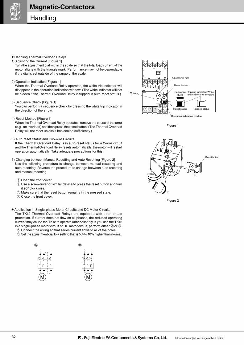
Handling Thermal Overload Relays1) Adjusting the Current [Figure 1]
Turn the adjustment dial within the scale so that the total load current of the motor aligns with the triangle mark. Performance may not be dependable if the dial is set outside of the range of the scale.
2) Operation Indication [Figure 1]When the Thermal Overload Relay operates, the white trip indicator will disappear in the operation indication window. (The white indicator will not be hidden if the Thermal Overload Relay is tripped in auto-reset status.)
3) Sequence Check [Figure 1]You can perform a sequence check by pressing the white trip indicator in the direction of the arrow.
4) Reset Method [Figure 1]When the Thermal Overload Relay operates, remove the cause of the error (e.g., an overload) and then press the reset button. (The Thermal Overload Relay will not reset unless it has cooled sufficiently.)
5) Auto-reset Status and Two-wire CircuitsIf the Thermal Overload Relay is in auto-reset status for a 2-wire circuit and the Thermal Overload Relay resets automatically, the motor will restart operation automatically. Take adequate precautions for this.
6) Changing between Manual Resetting and Auto Resetting [Figure 2] Use the following procedure to change between manual resetting and auto resetting. Reverse the procedure to change between auto resetting and manual resetting.
① Open the front cover. ② Use a screwdriver or similar device to press the reset button and turn
it 90° clockwise. ③ Make sure that the reset button remains in the pressed state. ④ Close the front cover.
Application in Single-phase Motor Circuits and DC Motor CircuitsThe TK12 Thermal Overload Relays are equipped with open-phase protection. If current does not flow on all phases, the reduced operating current may cause the TK12 to operate unnecessarily. If you use the TK12 in a single-phase motor circuit or DC motor circuit, perform either ○A or ○B . ○A Connect the wiring so that series current flows to all of the poles. ○B Set the adjustment dial to a setting that is 5% to 10% higher than normal.
Figure 1
mark
Adjustment dial
Reset button
Operation indication window
Reset status Tripped status
Sequencecheck
Tripping indicator: White(Shown in black for this description.)
A B
M M
Reset button
①
②
③
④
Figure 2
Handling

3333
SK SeriesMagnetic-Contactors
Information subject to change without notice
Example: Calculation Method for Dial Adjustment at an Ambient Temperature of 55°C
Dial current at 20°C
Compensation coefficient at ambient temperature of 55°C
Dial current at ambient temperature of 55°C=
Ambient Temperature Compensation CharacteristicsChanges in the ambient environment will affect the operation of the Thermal Overload Relay. The operational current will be higher at lower temperatures and lower at higher temperatures, i.e., compensation of operating characteristics will not be complete. Adjust the current according to the application environment.The compensation coefficient for adjusting the current depends on the ambient temperature, as shown in Figure 3. If the ambient temperature in the application changes greatly, e.g., by 20°C, use the following example as a guide to calculate the adjusted current value after compensation.
Mounting the Thermal Overload Relay to and Removing It from the Magnetic Contactor
I. Mounting [Figure 4]1) Loosen terminals 2, 4, and 6 on the Magnetic Contactor.2) Insert the posts on the Thermal Overload Relay into the holes
on the Magnetic Contactor in the direction shown by the arrows.3) Insert the main circuit section of the Thermal Overload Relay on
the right sides of the terminal screws.4) Tighten the terminal screws on the Magnetic Contactor to the
specified torque.II. Removing [Figure 4]
1) Loosen the terminals screws on the Magnetic Contactor.2) Move the Thermal Overload Relay left and right and pull it free
from the Magnetic Contactor.
Figure 4
Figure 5
②③
Figure 3
Ambient temperature [°C]
Adjusted current at the maximum scale value
Adjusted current at the minimum scale value
Compensationcoefficient
1.2
0.8
1.1
1.0
0.9
-10 0 10 20 30 40 50 60
Refresh recommendation
The main contacts, mechanical components, and other parts in Fuji magnetic contactors and switches have a wear life expectancy based on the number of times they are switched. Coil electric wires and electronic components in electronic units have a life expectancy based on degradation over time according to the environment and conditions they are used in.We recommend refreshing Fuji magnetic contactors and switches when they reach the specified number of times switched as noted in the user’s manual or catalog, or roughly 10 years from the manufacture date under standard usage conditions as noted in the “Survey Concerning Recommended Refresh Periods for Low Voltage Devices” report published by The Japan Electrical Manufacturers’ Association (JEMA).

Magnetic-Contactors
3434
Magnetic-Contactors
Information subject to change without notice
SK12L
Magnetic Contactors
Features International safety standards for standard models (IEC, GB, JIS, UL, and CSA).
Models available with AC or DC operating coils (DC: 2.4W and 1.2W models only).
Many optional units. - Auxiliary Contact Blocks (2-pole or 4-pole) - Coil Surge Suppression Units - Interlock Units
Easier Thermal Overload Relay wiring. The terminal arrangement separates main circuit wires and auxiliary
circuit wires for easier wiring.
①Series②Frame size③Operating coil specification
④Auxiliary contact specification⑤Coil voltage specification ⑥Auxiliary contact arrangement
Ordering Information (Types)
SK 06 A H - E 10① ② ③ ④ ⑤ ⑥
Magnetic Contactors
Ratings and Types
Magnetic Contactors SK06, 09, 12
Framesize②
Max. motor capacity [kW] Rated operational current [A] Conventional free air thermalcurrent [A] (Rated thermal current)
Operating coilspecification③
Auxiliary contactspecification④
Auxiliary contactarrangement⑥
Type
3-phase squirrel-cage motor(AC-3)
3-phase squirrel-cage motor(AC-3)
Resistive load(AC-1)
200-240V
380-440V
500-550V
200-240V
380-440V
500-550V
200-240V
380-440V
6A[06]
1.5 2.2 3 6 6 5 12 12 20 AC-operated[A]
Bifurcated [blank] 1NO [10]1NC [01]
SK06A-□▲Single [H] SK06AH-□▲
DC-operated (2.4W) [G]
Bifurcated [blank] SK06G-□▲Single [H] SK06GH-□▲
DC-operated (1.2W)[L]
Bifurcated [blank] SK06L-□▲Single [H] SK06LH-□▲
9A[09]
2.2 4 4 9 9 7 16 16 AC-operated [A]
Bifurcated [blank] SK09A-□▲Single [H] SK09AH-□▲
DC-operated (2.4W)[G]
Bifurcated [blank] SK09G-□▲Single [H] SK09GH-□▲
DC-operated (1.2W)[L]
Bifurcated [blank] SK09L-□▲Single [H] SK09LH-□▲
12A[12]
3 5.5 5.5 12 12 9 20 20 AC-operated[A]
Bifurcated [blank] SK12A-□▲Single [H] SK12AH-□▲
DC-operated (2.4W)[G]
Bifurcated [blank] SK12G-□▲Single [H] SK12GH-□▲
DC-operated (1.2W)[L]
Bifurcated [blank] SK12L-□▲Single [H] SK12LH-□▲
Note 1. “□” in the type column is replaced with the coil voltage code.Note 2. “▲” in the type column is replaced with the auxiliary contact arrangemant code.Note 3. Numbers and letters in brackets [ ] are used in the product code.
Magnetic Contactors

3535
SK SeriesMagnetic-Contactors
Information subject to change without notice
Magnetic Contactors SK18, 22, 32
Framesize②
Max. motor capacity [kW] Rated operational current [A] Conventional free air thermalcurrent [A] (Rated thermal current)
Operating coilspecification③
Auxiliary contactspecification④
Auxiliary contactarrangement⑥
Type
3-phase squirrel-cage motor(AC-3)
3-phase squirrel-cage motor(AC-3)
Resistive load(AC-1)
200-240V
380-440V
500-550V
200-240V
380-440V
500-550V
200-240V
380-440V
18A[18]
4.5 7.5 7.5 18 32 32 32 32 32 AC-operated[A]
Bifurcated [blank] 1NO [10]1NC [01]
SK18A-□▲Single [H] SK18AH-□▲
DC-operated (2.4W) [G]
Bifurcated [blank] SK18G-□▲Single [H] SK18GH-□▲
22A[22]
5.5 11 11 22 32 32 32 32 32 AC-operated [A]
Bifurcated [blank] SK22A-□▲Single [H] SK22AH-□▲
DC-operated (2.4W)[G]
Bifurcated [blank] SK22G-□▲Single [H] SK2GH-□▲
32A[32]
7.5 15 15 32 40 40 40 40 40 AC-operated[A]
Bifurcated [blank] SK32A-□▲Single [H] SK32AH-□▲
DC-operated (2.4W)[G]
Bifurcated [blank] SK32G-□▲Single [H] SK32GH-□▲
Note 1. “□” in the type column is replaced with the coil voltage code.Note 2. “▲” in the type column is replaced with the auxiliary contact arrangemant code.Note 3. Numbers and letters in brackets [ ] are used in the product code.
Coil voltage ⑤AC-operated Order Voltage 24 48 100 110 120 200 220 240 380 400 440 500
Product code E F 1 H K 2 M P S 4 T 5DC-operated(2.4W) Order Voltage 12 24 48 60 100 110 120 200 210 220
Product code B E F G 1 H K 2 Y MDC-operated(1.2W) Order Voltage 12 24 48
Product code B E F

3636
Magnetic-Contactors
Information subject to change without notice
Dimensions, mm
Magnetic Contactors SK06, SK09, SK12
SK18A, SK22A
SK18G, SK22G
(34)*1
(17)*2
6
61 (rail height 15)
36
49
Mounting hole2-M4
40
Coil terminalM3.5
Aux. terminalM3.5
Main terminalM3.5
7.7
48 31
45
8.7
*: For DC-operated
*
*
Mass: 0.14kg (For AC-operated)0.17kg (For DC-operated)
Use the two mounting holes on a diagonal
Aux. contact Contact arrangement
1NO
1NC
Pannel drilling
Note: *1 With SZ1KA auxiliary contact blocks. *2 With SZ1FA auxiliary contact blocks.
-A214 T36T24T12
+A1NO13L35L231 L1
35
*
*
*
*
*
*
A1 (+)
A2 (-)
14
13 5/L3 3/L2 1/L1
2/T1 4/T2 6/T3 A2 (-)
A1 (+)
1/L1
2/T1 6/T3 4/T2
3/L2 5/L3 21
22
7.7
9.7
11.4
6.5
45
57.5
57.5
81
432320
49
8.5
61
2881
92
35
34
18.5(
to 2
0.5)
(48
to)
52
2-M4Mounting hole
6014
.5
M3.5Coil terminal
Main terminalM4
M3.5Aux. terminal
*1
(rail height 15)
*1
*2
*2
Use the two mounting holes on a diagonal
① 35 x 60
② 34 x (48 to ) 52: Convertible with SC-4-0,SC-4-1
①
②
Pannel drilling
Note:
*1 With font mounting auxiliary contact block*2 With side mounting auxiliary contact block
22
21 5/L3 3/L2
4/T2 6/T3
1/L1
A1 A2
1NC
1NO
Contact arrangementAux. contact
6/T3 4/T2 2/T1
2/T1
1/L1 3/L2 5/L3 13
14
A1 A2
A2A1
1L1
2T1
3L2
4T2
5L3
6T3
13
14
Mass: 0.34kg
81
432320
49
7.7
9.7
11.4
6.5
45
57.5
57.52894
74
8.5
104
Aux. terminalM3.5
M4Main terminal
Coil terminalM3.5
(rail height 15)
*1
*1
*2
*2
14.5
60
Mounting hole2-M4
(48
to) 5
218
.5 (
to 2
0.5) 34
35
Pannel drilling
14
13
6T3
5L3
4T2
3L2
2T1
1L1
A1 A2
①
②
Use the two mounting holes on a diagonal
① 35 x 60
② 34 x (48 to ) 52: Convertible with SC-4-0/G,SC-4-1/G
22
21 5/L3 3/L2
4/T2 6/T3
1/L1
(+)A1
(-)A2
(+)A1
(-)A2
1NC
1NO
Contact arrangementAux. contact
6/T3 4/T2 2/T1
2/T1
1/L1 3/L2 5/L3 13
14
Mass: 0.43kgNote:
*1 With font mounting auxiliary contact block
*2 With side mounting auxiliary contact block
Magnetic Contactors
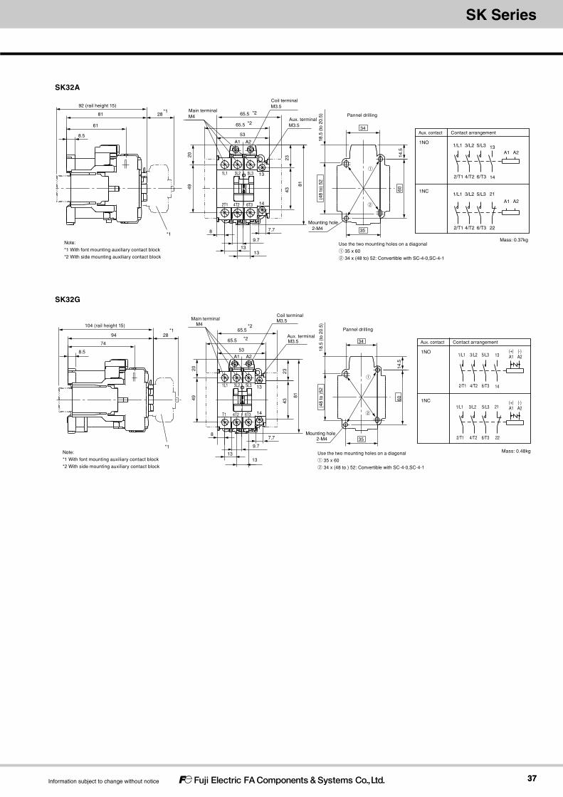
3737
SK SeriesMagnetic-Contactors
Information subject to change without notice
SK32A
22
21 5/L3 3/L2
4/T2 6/T3
1/L1
A1 A2
1NC
1NO
Contact arrangementAux. contact
6/T3 4/T2 2/T1
2/T1
1/L1 3/L2 5/L3 13
14
A1 A2
A1 A2
1L1 3L2 5L3 13
2T1 4T2 6T3 14
53
2049
8
13
43
81
13
9.7
7.7
61
92 (rail height 15)
81
8.5
28
34
35
60
(48
to)
5218
.5 (
to 2
0.5)
14.5
23
*1
*1 *2
*2
65.5
65.5Aux. terminalM3.5
Coil terminalM3.5
Main terminalM4
Mounting hole2-M4
Pannel drilling
Mass: 0.37kgUse the two mounting holes on a diagonal
① 35 x 60
② 34 x (48 to) 52: Convertible with SC-4-0,SC-4-1
①
②
Note:
*1 With font mounting auxiliary contact block
*2 With side mounting auxiliary contact block
SK32G
146T3T1 4T2
1L1 3L2 5L3 13
A2A1
34
Mounting hole2-M4
M4Main terminal
*2
*265.5
65.5Aux. terminalM3.5
M3.5Coil terminal
*1
*1
53
2049
8
13
2343
81
13
9.7
7.7
28
35
60
(48
to )
5218
.5 (
to 2
0.5)
14.5
74
104 (rail height 15)
94
8.5
Pannel drilling
22
21 5/L3 3/L2
4/T2 6/T3
1/L11NC
1NO
Contact arrangementAux. contact
6/T3 4/T2 2/T1
2/T1
1/L1 3/L2 5/L3 13
14
Mass: 0.48kgUse the two mounting holes on a diagonal
① 35 x 60
② 34 x (48 to ) 52: Convertible with SC-4-0,SC-4-1
①
②
(+)A1
(-)A2
(+)A1
(-)A2
Note:
*1 With font mounting auxiliary contact block
*2 With side mounting auxiliary contact block

Magnetic-Contactors
3838
Magnetic-Contactors
Information subject to change without notice
Reversing Magnetic Contactors
SK12AR
Features Ideal for forward/reverse motor operation and plugging. Mechanical interlock provided as a standard feature.
①Series②Frame size③Operating coil specification ④Auxiliary contact specification
⑤Reversing⑥Coil voltage specification⑦Auxiliary contact arrangement⑧Reversing connection
Ordering Information (Types)
SK 06 A H R - E 10 W① ② ③ ④ ⑤ ⑥ ⑦ ⑧
Reversing Magnetic Contactors
Ratings and Types
Reversing Magnetic Contactors SK06, SK09, SK12
Framesize②
Max. motor capacity [kW]
Rated operational current[A]
Conventionalfree air thermal current[A] (Rated thermal current)
Operatingcoilspecification③
Auxiliarycontactspecification④
Auxiliarycontactarrangement⑦
Type
3-phase squirrel-cage motor(AC-3)
3-phase squirrel-cage motor(AC-3)
Resistive load(AC-1)
200-240V
380-440V
500-550V
200-240V
380-440V
500-550V
200-240V
380-440V
6A[06]
1.5 2.2 3 6 6 5 12 12 20 AC-operated [A] Bifurcated [blank] 1NO x 2 [10]1NC x 2 [01]
SK06AR-□▲WSingle [H] SK06AHR-□▲W
DC-operated (2.4W)[G]
Bifurcated [blank] SK06GR-□▲WSingle [H] SK06GHR-□▲W
DC-operated (1.2W)[L]
Bifurcated [blank] SK06LR-□▲WSingle [H] SK06LHR-□▲W
9A[09]
2.2 4 4 9 9 7 16 16 AC-operated[A]
Bifurcated [blank] SK09AR-□▲WSingle [H] SK09AHR-□▲W
DC-operated (2.4W)[G]
Bifurcated [blank] SK09GR-□▲WSingle [H] SK09GHR-□▲W
DC-operated (1.2W)[L]
Bifurcated [blank] SK09LR-□▲WSingle [H] SK09LHR-□▲W
12A[12]
3 5.5 5.5 12 12 9 20 20 AC-operated[A]
Bifurcated [blank] SK12AR-□▲WSingle [H] SK12AHR-□▲W
DC-operated (2.4W)[G]
Bifurcated [blank] SK12GR-□▲WSingle [H] SK12GHR-□▲W
DC-operated (1.2W)[L]
Bifurcated [blank] SK12LR-□▲WSingle [H] SK12LHR-□▲W
Note 1. “□” in the type column is replaced with the coil voltage code.Note 2. “▲” in the type column is replaced with the auxiliary contact arrangemant code.Note 3. Numbers and letters in brackets [ ] are used in the product code.Note 4. An electrical interlock is not implemented on Magnetic Contactors with an auxiliary contact arrangement of 1NOx2. When using these Magnetic Contactors, always implement an electrical interlock in the external control circuits to prevent short-circuit faults when power is turned ON.Note 5. An electrical interlock is implemented in the auxiliary circuit configurations of the Magnetic Contactor. If you need to use an auxiliary contact, add an option Auxiliary Contact Blocks.
Reversing Magnetic Contactors

3939
SK SeriesMagnetic-Contactors
Information subject to change without notice
Reversing Magnetic Contactors SK18, SK22, SK,32
Framesize②
Max. motor capacity [kW]
Rated operational current[A]
Conventionalfree air thermal current[A] (Rated thermal current)
Operatingcoilspecification③
Auxiliarycontactspecification④
Auxiliarycontactarrangement⑦
Type
3-phase squirrel-cage motor(AC-3)
3-phase squirrel-cage motor(AC-3)
Resistive load(AC-1)
200-240V
380-440V
500-550V
200-240V
380-440V
500-550V
200-240V
380-440V
18A[18]
4.5 7.5 7.5 18 18 13 32 32 32 AC-operated [A] Bifurcated [blank] 1NO x 2 [10]1NC x 2 [01]
SK18AR-□▲WSingle [H] SK18AHR-□▲W
DC-operated (2.4W)[G]
Bifurcated [blank] SK18GR-□▲WSingle [H] SK18GHR-□▲W
22A[22]
5.5 11 11 22 22 17 32 32 32 AC-operated[A]
Bifurcated [blank] SK22AR-□▲WSingle [H] SK22AHR-□▲W
DC-operated (2.4W)[G]
Bifurcated [blank] SK22GR-□▲WSingle [H] SK22GHR-□▲W
32A[32]
7.5 15 15 32 32 24 40 40 40 AC-operated[A]
Bifurcated [blank] SK32AR-□▲WSingle [H] SK32AHR-□▲W
DC-operated (2.4W)[G]
Bifurcated [blank] SK32GR-□▲WSingle [H] SK32GHR-□▲W
Note 1. “□” in the type column is replaced with the coil voltage code.Note 2. “▲” in the type column is replaced with the auxiliary contact arrangemant code.Note 3. Numbers and letters in brackets [ ] are used in the product code.Note 4. An electrical interlock is not implemented on Magnetic Contactors with an auxiliary contact arrangement of 1NOx2. When using these Magnetic Contactors, always implement an electrical interlock in the external control circuits to prevent short-circuit faults when power is turned ON.Note 5. An electrical interlock is implemented in the auxiliary circuit configurations of the Magnetic Contactor. If you need to use an auxiliary contact, add an option Auxiliary Contact Blocks.
Coil voltage ⑥AC-operated Order Voltage 24 48 100 110 120 200 220 240 380 400 440 500
Product code E F 1 H K 2 M P S 4 T 5DC-operated(2.4W) Order Voltage 12 24 48 60 100 110 120 200 210 220
Product code B E F G 1 H K 2 Y MDC-operated(1.2W) Order Voltage 12 24 48
Product code B E F

4040
Magnetic-Contactors
Information subject to change without notice
Dimensions, mm
Magnetic Contactors SK06□R, SK09□R, SK12□R
SK18AR, SK22AR
14
13
2T1 4T2 6T3 A2
A15L33L21L1
A2146T34T22T1
A1135L33L21L1
1NO x 2
Implement an electricalinterlock separately
1NC x 2
Coil terminalM3.5
Aux. terminalM3.5
Main terminalsM3.5
90.545.5
Ap
prox
. 5A
ppr
ox. 5
48
10.77.78.7
31
*1
(34)*15668 (rail height: 15)
6
36
Mounting Hole Dimensions
40
80.5 Mounting holes4-M4
2/T1
4/T2
6/T3
5/L3
3/L2
1/L1
2/T1 4/T2
6/T3 14
13 5/L3
3/L2 1/L1 13
14
(+)A1
A2(-)
*2
*2
(+)*2A1
*2
*2
A2(-)*2
22
21 1/L1 3/L2
5/L3
21
226/T3
4/T2
2/T1
1/L1 3/L2
5/L3
6/T3
4/T2
2/T1 A2(-)*2
*2
*2
A2(-)
(+)A1
(+)*2A1
Wiring diagram
*1 With Auxiliary Contact Blocks
*2 For DC-operated types.
[NOTE]
Mass: 0.32kg (AC-operated type)
0.38kg (DC-operated type)
Main terminalsM4
Coil terminalM3.5
Aux. terminalM3.5
103
8123
App
rox.
5A
ppro
x. 5
43
7.7
11.411.4
6.5
9.7
4920
Mounting holes4-M4
18.6
(48
to)
52
58
34 3424
58
*1
92 (rail height: 15)
81 28 *1
61
8.5
Mounting Hole Dimensions
1NO x 2
1NC x 2
Wiring diagramA2A1
1L1
2T1
3L2
4T2
5L3
6T3
21
22
1L1
2T1
3L2
4T2
5L3
6T3
21
22
A1 A2
*1 With Auxiliary Contact Block.
Mass: 0.73kg
21 21
14
13A113
14
A2 A1 A2
22 22
A1 A2 A1 A2
1/L1 3/L2 5/L3
2/T1 4/T2 6/T3 2/T1 4/T2 6/T3
5/L3 3/L2 1/L1
1/L1 3/L2 5/L3
2/T1 4/T2 6/T3 2/T1 4/T2 6/T3
5/L3 3/L2 1/L1
Implement an electricalinterlock separately
SK18GR, SK22GR
Mounting holes4-M4
18.6
(48
to)
52
58
34 3424
28 *194
74
8.5
104 (rail height: 15)
*1
Mounting Hole Dimensions
1NC x 2
1NO x 2
*1 With Auxiliary Contact Block.
Wiring diagram
Mass: 0.9kg
Main terminalsM4
Coil terminalM3.5
Aux. terminalM3.5
103
8123
App
rox.
10
App
rox.
543
7.7
11.411.4
6.5
9.7
4920
58
A2A1
1L1
2T1
3L2
4T2
5L3
6T3
21
22
1L1
2T1
3L2
4T2
5L3
6T3
21
22
A1 A2
1/L1
2/T1
A2A1A2
2/T1 4/T2 6/T3
5/L3 3/L2 1/L1
4/T2 6/T314
13 5/L3 3/L2A1 13
14
A2A1A2A1
2222
2121
(+) (-) (+) (-)
(+) (-) (+) (-) 1/L1 3/L2 5/L3
6/T34/T22/T1
1/L1 3/L2 5/L3
6/T34/T22/T1
Implement an electricalinterlock separately
Reversing Magnetic Contactors
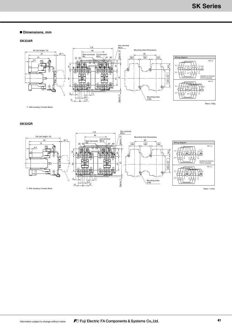
4141
SK SeriesMagnetic-Contactors
Information subject to change without notice
Dimensions, mm
SK32AR
Mounting holes4-M4
*1
Mounting Hole Dimensions119
66
App
rox.
581
2343
9.7
7.7
13 13
8
4920
Coil terminalM3.5
Aux. terminalM3.5
Main terminalsM4
App
rox.
10
66
343234
(48
to)
5218
.5
28 *1
92 (rail height: 15)
81
61
8.5
22
21
22
21
6T3
5L3
6T3
5L3
4T2
3L2
4T2
3L2
2T1
1L1
2T1
1L1
A1 A2 A1 A2
*1 With Auxiliary Contact Block.
A1 A2
A2
A1 A2
1NC x 2
1NO x 2
14
13 1/L1 3/L2
5/L3
13
146/T3
4/T2
2/T1
1/L1
3/L2
5/L3
6/T3
4/T2
2/T1
A1 A2
A2
A1 A2
22
21 1/L1 3/L2
5/L3
21
226/T3
4/T2
2/T1
1/L1
3/L2
5/L3
6/T3
4/T2
2/T1
Wiring diagram
Mass: 0.8kg
Implement an electricalinterlock separately
SK32GR
Mounting holes4-M4
*1
Mounting Hole Dimensions
App
rox.
10
Main terminalsM4
Aux. terminalM3.5
Coil terminalM3.5
2049
8
1313
7.7
9.7
4323
81A
ppro
x. 5
66
119
104 (rail height: 15)
28 *194
74
8.5
66
343234
(48
to)
5218
.5
A2A1A2A1
1L1
2T1
1L1
2T1
3L2
4T2
3L2
4T2
5L3
6T3
5L3
6T3
21
22
21
22
*1 With Auxiliary Contact Block.
(+)A1
(-)A2
(+)A1
(-)A2
1NC x 2
1NO x 2
14
13 1/L1 3/L2
5/L3
13
146/T3
4/T2
2/T1
1/L1
3/L2
5/L3
6/T3
4/T2
2/T1
Wiring diagram
Mass: 1.01kg
(+)A1
(-)A2
(+)A1
(-)A2
22
21 1/L1 3/L2
5/L3
21
226/T3
4/T2
2/T1
1/L1
3/L2
5/L3
6/T3
4/T2
2/T1
Implement an electricalinterlock separately

4242
Magnetic-Contactors
Information subject to change without notice
SK12FL
SK12EL
SK12FLType
(Contact arrangement)
SK12EL
(4A)
SK12FL
(2A2B)
1/L1 3/L2 5/L3 7/L4
2/T1 4/T2 6/T3 8/T4
A2(ー)
A1(+)
1 R1 R3 3
2 R2 R4 4 A2(ー)
A1(+)
Contact arrangement
diagram
(34) *1
(17) *26
TerminalM3.5
61 (rail height: 15)
3649
7.7
45
8.7
48 31
Coil terminalM3.5
Mounting holes2×M4
35
*1 When an auxiliary contact block (SZ1KA20, 11, 02) (front mounting)
was installed
*2 When an auxiliary contact block (SZ1FA11) (front mounting) was installed
Mounting Hole Dimensions
40
●Mounting screw : 2-M4
Install using two mounting holes in opposite corners.
ーA2
+A1
T48
L47
2 T1 4 T2 6 T3
L35L23L11
Main contact 4-pole magnetic contactor
Features Perfect for applications where four wires are required for the main circuit
4NO product and 2NO2NC product main contacts are available The operation coil is a low consumption unit with a power consumption of 1.2 W.
①Basic types②Coil voltage specification
Ordering Information (Types)
SK12EL - E① ②
Main contact 4-pole magnetic contactor Coil voltage specification code
Ratings and Types
Performance
Dimensions, mm
Coil voltage ② Code Coil specification
12V DC24V DC
BE
A1(+)
A2(-)
(Note 1) The allowable power fluctuation range is 85 to 110% of the rated voltage.(Note 2) Be careful, as operating coil terminals have polarity.
Main contact (NO) Main contact (NC) Conventional free air thermal current [A] (Rated thermal current)
Main contact arrangement
Type
Max. motor capacity [kW] Rated operational current [A] Rated operational current [A]
3-phase squirrel-cage motor (AC-3)
3-phase squirrel-cage motor (AC-3)
Resistive load (AC-1)
Resistive load (AC-1)
200-240V
380-440V
500-550V
200-240V
380-440V
500-550V
200-240V
380-440V
200-240V
380-440V
500-550V
3 5.5 5.5 12 12 9 20 20 – – – 20 4NO SK12EL-□– – – – – – 10 10 5 2NO2NC SK12FL-□
(Note 1) This product is not equipped with auxiliary contacts. If necessary, combine it with a 2-pole auxiliary contact block product.(Note 2) It cannot be combined with a 4-pole auxiliary contact block product.
Type Rated operational voltage[V]
Rated operational current[A]
Making/breaking current [A] Operating cycles per hour [times hour]
Durability (Operations) Performance indicationMaking Breaking Mechanical Electrical
SK12EL-□SK12FL-□
220 12 144 120 1800 1000 100 AC-3·0·0-0
440 12 144 120
Mass:0.14kg(ACoperated) 0.17kg(DCoperated)
Main contact 4-pole magnetic contactor
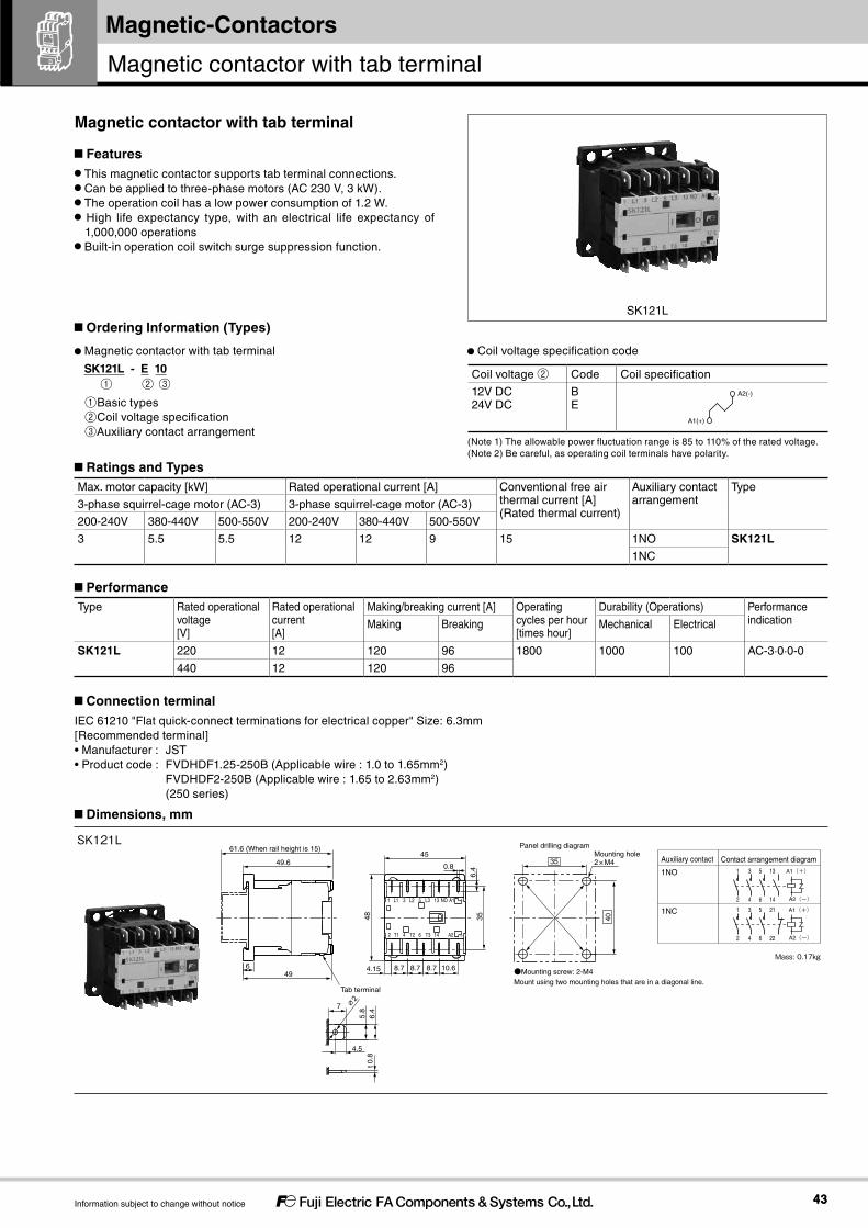
4343
Magnetic-Contactors
Information subject to change without notice
SK121L
SK121L
Mass:0.17kg
Auxiliary contact
1NO
1NC
1 3 5 13
2 4 6 14
A2(ー)
A1(+)
1 3 5 21
2 4 6 22 A2(ー)
A1(+)
Contact arrangement diagram49.645
0.8
649
4.15 8.7 8.7 8.7 10.6
48
6.4
35
6.4
5.8
∅2
4.5
t 0.
8
Tab terminal
7
2 T1 4 T2 6 T3 14 A2 ー
+A1NO13L35L23L11
2×M4 35
Panel drilling diagram
40
●Mounting screw: 2-M4Mount using two mounting holes that are in a diagonal line.
Mounting hole 61.6 (When rail height is 15)
Magnetic contactor with tab terminal
Features This magnetic contactor supports tab terminal connections. Can be applied to three-phase motors (AC 230 V, 3 kW). The operation coil has a low power consumption of 1.2 W. High life expectancy type, with an electrical life expectancy of 1,000,000 operations
Built-in operation coil switch surge suppression function.
Connection terminalIEC 61210 "Flat quick-connect terminations for electrical copper" Size: 6.3mm[Recommended terminal]• Manufacturer : JST• Product code : FVDHDF1.25-250B (Applicable wire : 1.0 to 1.65mm2) FVDHDF2-250B (Applicable wire : 1.65 to 2.63mm2) (250 series)
①Basic types②Coil voltage specification③Auxiliary contact arrangement
Ordering Information (Types)
SK121L - E 10① ② ③
Magnetic contactor with tab terminal Coil voltage specification code
Coil voltage ② Code Coil specification
12V DC24V DC
BE
A1(+)
A2(-)
(Note 1) The allowable power fluctuation range is 85 to 110% of the rated voltage.(Note 2) Be careful, as operating coil terminals have polarity.
Ratings and Types
Performance
Max. motor capacity [kW] Rated operational current [A] Conventional free air thermal current [A] (Rated thermal current)
Auxiliary contact arrangement
Type
3-phase squirrel-cage motor (AC-3) 3-phase squirrel-cage motor (AC-3)
200-240V 380-440V 500-550V 200-240V 380-440V 500-550V
3 5.5 5.5 12 12 9 15 1NO SK121L1NC
Type Rated operational voltage[V]
Rated operational current[A]
Making/breaking current [A] Operating cycles per hour [times hour]
Durability (Operations) Performance indicationMaking Breaking Mechanical Electrical
SK121L 220 12 120 96 1800 1000 100 AC-3·0·0-0
440 12 120 96
Dimensions, mm
Magnetic contactor with tab terminal
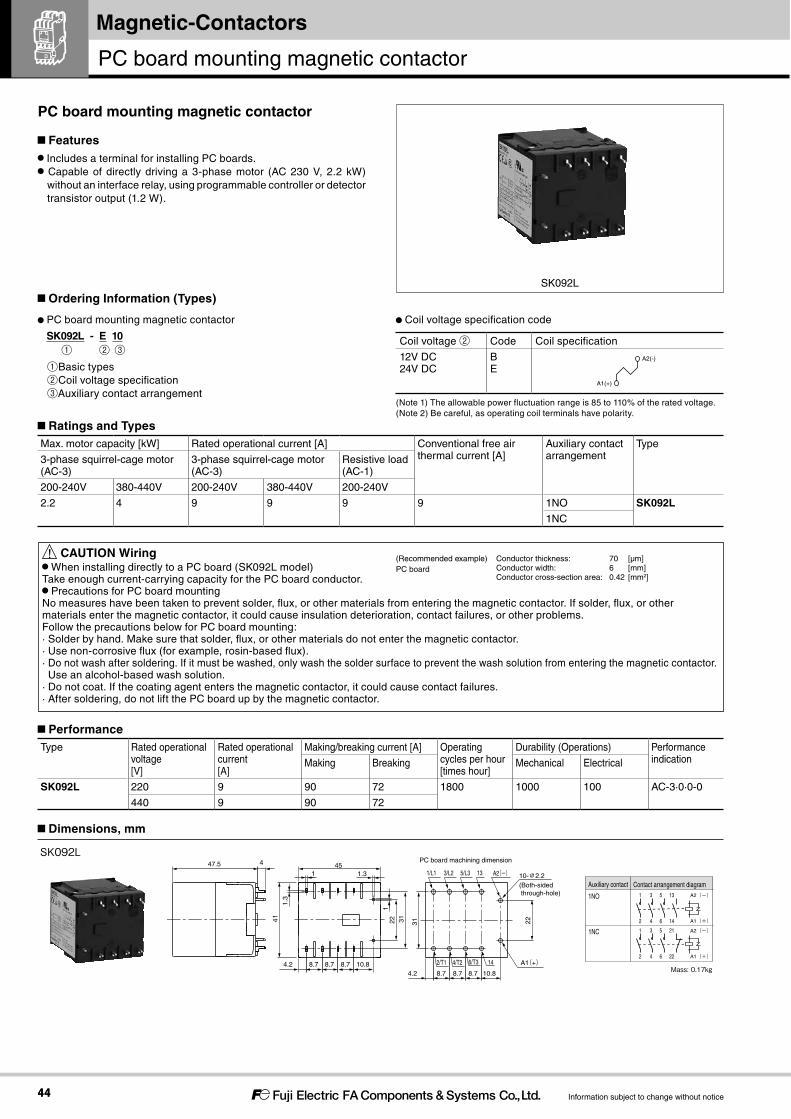
4444
Magnetic-Contactors
Information subject to change without notice
SK092L
Mass:0.17kg
SK092L
4.2 8.7 8.7 8.7 10.8
2231
47.5 4
41
45
22 31
4.2 8.7 8.7 8.7 10.8
1.3
1
1
1.3 135/L33/L21/L1
146/T32/T1 4/T2 A1(+)
PC board machining dimension
A2(ー) 10-∅2.2(Both-sided through-hole)
Auxiliary contact
1NO
1NC
1 3 5 13
2 4 6 14
A2(ー)
1 3 5 21
2 4 6 22
A1(+)
A2(ー)
A1(+)
Contact arrangement diagram
PC board mounting magnetic contactor
Features Includes a terminal for installing PC boards. Capable of directly driving a 3-phase motor (AC 230 V, 2.2 kW) without an interface relay, using programmable controller or detector transistor output (1.2 W).
! CAUTION Wiring When installing directly to a PC board (SK092L model)
Take enough current-carrying capacity for the PC board conductor. Precautions for PC board mounting
No measures have been taken to prevent solder, flux, or other materials from entering the magnetic contactor. If solder, flux, or other materials enter the magnetic contactor, it could cause insulation deterioration, contact failures, or other problems.Follow the precautions below for PC board mounting:· Solder by hand. Make sure that solder, flux, or other materials do not enter the magnetic contactor.· Use non-corrosive flux (for example, rosin-based flux).· Do not wash after soldering. If it must be washed, only wash the solder surface to prevent the wash solution from entering the magnetic contactor. Use an alcohol-based wash solution.· Do not coat. If the coating agent enters the magnetic contactor, it could cause contact failures.· After soldering, do not lift the PC board up by the magnetic contactor.
①Basic types②Coil voltage specification③Auxiliary contact arrangement
Ordering Information (Types)
SK092L - E 10① ② ③
PC board mounting magnetic contactor Coil voltage specification code
Coil voltage ② Code Coil specification
12V DC24V DC
BE
A1(+)
A2(-)
(Note 1) The allowable power fluctuation range is 85 to 110% of the rated voltage.(Note 2) Be careful, as operating coil terminals have polarity.
Ratings and TypesMax. motor capacity [kW] Rated operational current [A] Conventional free air
thermal current [A]Auxiliary contact arrangement
Type
3-phase squirrel-cage motor (AC-3)
3-phase squirrel-cage motor (AC-3)
Resistive load (AC-1)
200-240V 380-440V 200-240V 380-440V 200-240V
2.2 4 9 9 9 9 1NO SK092L1NC
Dimensions, mm
PerformanceType Rated operational
voltage[V]
Rated operational current[A]
Making/breaking current [A] Operating cycles per hour [times hour]
Durability (Operations) Performance indicationMaking Breaking Mechanical Electrical
SK092L 220 9 90 72 1800 1000 100 AC-3·0·0-0
440 9 90 72
(Recommended example)PC board
Conductor thickness: 70 [μm]Conductor width: 6 [mm]Conductor cross-section area: 0.42 [mm2]
PC board mounting magnetic contactor

4545
Magnetic-Contactors
Information subject to change without notice
TK12
Thermal Overload Relay
Features International safety standards for standard models (IEC, GB, JIS, UL, and CSA).
A terminal cover and dial cover are provided as standard features. Highly reliable 1NO1NC isolated auxiliary contacts to enable using NC and NO contacts at different potentials.
Easily switch between manual and automatic reset. Parallel arrangement of main terminals and auxiliary terminals for easier wiring.
①Type②Frame size③Mounting * TK12 only④Reset method ⑤Ampere setting range * * Refer to Heat Element Rating Specification Codes.
Ordering Information (Types)
TK 12 W A - 009① ② ③ ④ ⑤
Thermal Overload Relay
Ratings and Types
TypeTK12W□-■■■TK25□-■■■TK26□-■■■Note. “□” in the type column is replaced with the reset method code. “■■■” is replaced by the specified code for the current setting range.
Ampere Setting Range Specification Codes
Type Ampere setting range (A) Ordering code Applicable magnetic contactors
TK12 TK25 TK26 0.1 - 0.15 P10
SK06SK09
SK12SK18
SK22 SK32
0.13 - 0.2 P13 0.18 - 0.27 P18 0.24 - 0.36 P24 0.34 - 0.52 P34 0.48 - 0.72 P48 0.64 - 0.96 P64 0.8 - 1.2 P80 0.95 - 1.45 P95 1.1 - 1.65 1P1 1.4 - 2.1 1P4 1.7 - 2.6 1P7 2.2 - 3.4 2P2 2.8 - 4.2 2P8 4 - 6 004 5 - 7.5 005
−
6 - 9 006 7 - 10.5 007
−
9 - 13 009− 12 - 18 012
− 16 - 22 016
−− 20 - 26 020− 26 - 32 026
TK25
Thermal Overload Relay

4646
Magnetic-Contactors
Information subject to change without notice
3-pole CircuitsStandard Operating limit Overload (hot start) Locked rotor (cold start) Ambient
temperatureNon-tripping Tripping
IEC 60947-4-1 105% le(for less than 2h)
120% le(for less than 2h)
Tripping class 10A: 150% le for less than 2min
Tripping class 10A: 720% le for 2 to 10 s max.
20℃
2-pole CircuitsStandard Phase-loss protection Non-tripping Operation (hot start) Ambient temperature
IEC 60947-4-1 Provided. 2-pole: 100% le1-pole: 90% le
2-pole: 115% le (for less than 2h)1-pole:0% le
20℃
Ratings for IEC Standard Compliance
Type Conventional free air thermal current [A] (Rated continuous current)
Rated operational current [A] Minimumvoltage and currentRated operational voltage [V] AC-15 (Ind. load) DC-13 (Ind. load)
NC contacts NO contacts NC contacts NO contacts
TK12 5 24 3 (0.5) 3 (0.5) 1.1(0.3) 1.1 (0.3) DC5V, 3mA
100-120 2.5 (0.5) 2.5 (0.5) 0.28 0.28
200-240 2 (0.5) 1.5 (0.5) 0.14 0.14
380-440 1 (0.5) 0.75 (0.5) −
500-600 0.6 (0.5) 0.6 (0.5) −
TK25TK26
5 24 3 (0.5) 3 (0.5) 1.1(0.3) 1.1 (0.3) DC5V, 3mA
100-120 2.5 (0.5) 2.5 (0.5) 0.28 0.28
200-240 2 (0.5) 2 (0.5) 0.14 0.14
380-440 1 (0.5) 1 (0.5) −
500-600 0.6 (0.5) 0.6 (0.5) −
Numbers in brackets ( ) are for automatic reset.
Ratings for UL and CSA Standard Compliance
Type Rated continuous current [A]
Rated operational current [A] Rating code
AC DC
Rated operational voltage [V] Making Breaking Rated operational voltage [V] Making Breaking AC DC
TK12TK25TK26
5 120 30 3 125 0.22 0.22 B600 R300
240 15 1.5
480 7.5 0.75 250 0.11 0.11
600 6 0.6
Auxiliary Circuit Ratings
Operating Characteristics (Specifications)
Thermal Overload Relay

4747
SK SeriesMagnetic-Contactors
Information subject to change without notice
Tripping Class 10A
TK12, TK25, TK26 series, Ambient temperature: 20°C
Operating Characteristics Curves (Average Values)
3-pole operating characteristic, hot characteristic
2-pole operating characteristic, cold characteristic
3-pole operating characteristic, cold characteristic
80
[Sec
onds
][M
inut
es]
Ope
rate
tim
e
Multiple of current setting x Ie[A]1597 108654321
20
30405060
1086543
2
20
30405060
1086543
2
10.80.60.50.40.3

4848
Magnetic-Contactors
Information subject to change without notice
9597
9698 6/T3 4/T2
Dimension A - Manually reset state: 5mm - Automatically reset state: 2mm
Mass : 0.1kg
2/T1
Wiring diagram
Main terminalsM3.5
Reset button
SK06, 09, 12
Trip indicator(sequence check)
Aux. terminalsM3.5 (NC)
Aux. terminalsM3.5 (NO)
39.
516
12.2
49.
5
4.9
40
A37
50
(97.
5)
7.78.7
4540.5
Dimensions, mm
Thermal Overload Relay TK12
TK25
TK26
81.5
68.5
D
Dimensions (mm)
68.5
55.5
C
SK18GSK22G
SK18ASK22A
Applicable contactorType B
81
94
Aux. terminalsM3.5 (NC)
Trip indicator(sequence check)
Reset button
Mass: 0.11kg
9.7
9798
9695
6T34T22T1
A
B
6.4
40
50.5
11.2
48
15.5
14
130
53
C
D
Dimension A - Manually reset state: 5mm - Automatically reset state: 2mm
Aux. terminalsM3.5 (NO)
Main terminalsM4
B
A
C
D9.811.2
48
53
130
14
40
50.5
15.3
6T34T22T1
9798
9695
8168.5
D
6855.5
C
SK32G
SK32AB8194
Applicable contactorType
Aux. terminalsM3.5 (NC)
Trip indicator(sequence check)
Reset button
Mass: 0.11kg
Dimension A - Manually reset state: 5mm - Automatically reset state: 2mm
Aux. terminalsM3.5 (NO)
Main terminalsM4Dimensions (mm)
9597
9698 6/T3 4/T2 2/T1
Wiring diagram
9597
9698 6/T3 4/T2 2/T1
Wiring diagram
Thermal Overload Relay
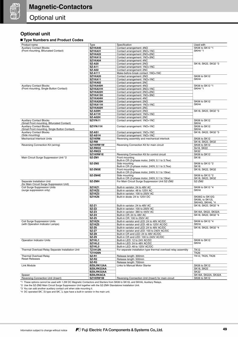
4949
Magnetic-Contactors
Information subject to change without notice
Type Numbers and Product CodesProduct name Type Specification Used withAuxiliary Contact Blocks (Front mounting, Bifurcated Contact)
SZ1KA40 Contact arrangement: 4NO SK06 to SK12 *1 SKH4 *1SZ1KA31 Contact arrangement: 3NO+1NC
SZ1KA22 Contact arrangement: 2NO+2NCSZ1KA13 Contact arrangement: 1NO+3NCSZ1KA04 Contact arrangement: 4NCSZ-A20 Contact arrangement: 2NO SK18, SK22, SK32 *3SZ-A11 Contact arrangement: 1NO+1NCSZ-A02 Contact arrangement: 2NCSZ-A111 Make-before-break contact: 1NO+1NCSZ1KA20 Contact arrangement: 2NO SK06 to SK12
SKH4SZ1KA11 Contact arrangement: 1NO+1NCSZ1KA02 Contact arrangement: 2NC
Auxiliary Contact Blocks (Front mounting, Single Button Contact)
SZ1KA40H Contact arrangement: 4NO SK06 to SK12 *1 SKH4 *1SZ1KA31H Contact arrangement: 3NO+1NC
SZ1KA22H Contact arrangement: 2NO+2NCSZ1KA13H Contact arrangement: 1NO+3NCSZ1KA04H Contact arrangement: 4NCSZ1KA20H Contact arrangement: 2NO SK06 to SK12
SKH4SZ1KA11H Contact arrangement: 1NO+1NC SZ1KA02H Contact arrangement: 2NCSZ-A20H Contact arrangement: 2NO SK18, SK22, SK32 *3SZ-A11H Contact arrangement: 1NO+1NCSZ-A02H Contact arrangement: 2NC
Auxiliary Contact Blocks (Small Front mounting, Bifurcated Contact)
SZ1FA11 Contact arrangement: 1NO+1NC SK06 to SK12 SKH4
Auxiliary Contact Blocks (Small Front mounting, Single Button Contact)
SZ1FA11H Contact arrangement: 1NO+1NC SK06 to SK12 SKH4
Auxiliary Contact Blocks (Side mounting)
SZ-AS1 Contact arrangement: 1NO+1NC SK18, SK22, SK32 *3SZ-AS1H Contact arrangement: 1NO+1NC
Mechanical Interlock Units SZ1KRM Reversing assembly and mechanical interlock SK06 to SK12SZ-RM SK18, SK22, SK32
Reversing Connection Kit (wiring) SZ1KRW1W Reversing Connection Kit for main circuit SK06 to SK12SZ-RW22 Sk18, SK22SZ-RW23 SK32SZ1KRW1E Reversing Connection Kit for control circuit SK06 to SK12
Main Circuit Surge Suppression Unit *2 SZ-ZM1 Front mounting Built-in CR (3-phase motor, 240V, 0.1 to 3.7kw)
SK18
SZ-ZM2 Side mounting Built-in CR (3-phase motor, 240V, 0.1 to 3.7kw)
SK06 to SK12 *2 SK18
SZ-ZM3E Front mounting Built-in CR (3-phase motor, 240V, 0.1 to 15kw)
SK18, SK22, SK32
SZ-ZM4E Side mounting Built-in CR (3-phase motor, 240V, 0.1 to 15kw)
SK06 to SK12 *2 SK18, SK22, SK32
Separate Installation Unit (for Main Circuit Surge Suppression Unit)
SZ-ZMH For Main Circuit Surge Suppression Unit SZ-ZM2 SZ-ZM2
Coil Surge Suppression Units (surge suppression only)
SZ1KZ1 Built-in varistor: 24 to 48V AC SK06 to SK12 *4 SKH4SZ1KZ2 Built-in varistor: 48 to 125V AC
SZ1KZ3 Built-in varistor: 100 to 250V ACSZ1KZ6 Built-in diode: 24 to 125V DC SK06G to SK12G
SK06L to SK12L SKH4G, SKH4L *4
SZ-Z1 Built-in varistor: 24 to 48V AC SK18, SK22, SK32 *4SZ-Z2 Built-in varistor: 100 to 250V ACSZ-Z3 Built-in varistor: 380 to 440V AC SK18A, SK22, SK32ASZ-Z4 Built-in CR: 24 to 48V AC SK18, SK22, SK32 *4SZ-Z5 Built-in CR: 100 to 250V AC
Coil Surge Suppression Units (with Operation Indicator Lamps)
SZ1KZ4 Built-in varistor and LED: 24 to 48V AC/DC SK06 to SK12 *4 SKH4SZ1KZ5 Built-in varistor and LED: 48 to 125V AC/DC
SZ-Z6 Built-in varistor and LED: 24 to 48V AC/DC SK18, SK22, SK32 *4SZ-Z7 Built-in varistor and LED: 100 to 240V AC/DC SZ-Z8 Built-in CR and LED: 24 to 48V AC/DC SZ-Z9 Built-in CR and LED: 100 to 240V AC/DC
Operation Indicator Units SZ1KL1 Built-in LED: 12 to 24V AC/DC SK06 to SK12 SKH4SZ1KL2 Built-in LED: 24 to 48V AC/DC
SZ1KL3 Built-in LED: 48 to 125V AC/DCThermal Overload Relay Separate Installation Unit TZ1H12N For separate installation type thermal overload relay assembly TK12
TZ1H26N TK26Thermal Overload Relay Reset Releases
SZ-R1 Release length: 300mm TK12, TK25, TK26SZ-R2 Release length: 500mmSZ-R3 Release length: 700mm
Link Module BZ0LRK12AA Links to Manual Motor Starter SK06 to SK12BZ0LRK22AA SK18, SK22BZ0LRK32AA SK32
Spaser BZ0LRKACA SK18A, SK22A, SK32AReversing Connection Unit (Insert) SZ1KRW1M Reversing Connection Unit (Insert) for main circuit SK06 to SK12
*1 These options cannot be used with 1.2W DC Magnetic Contactors and Starters from SK06 to SK12L and SKH4L Auxiliary Relays.*2 Use the SZ-ZM2 Main Circuit Surge Suppression Unit together with the SZ-ZMH Standalone Installation Unit.*3 You can add another auxiliary contact unit when side mounting it.*4 DC operated SK□G type and SK□L type have a built-in varistor in the main unit.
Optional unit
Optional unit

5050
Magnetic-Contactors
Information subject to change without notice
Product name Number of contacts Contact arrangement Mounting Used with Type
Auxiliary Contact Blockswith Bifurcated Contacts
4 4NO Front mounting SK06 to SK12 *1SKH4 *1
SZ1KA403NO+1NC SZ1KA312NO+2NC SZ1KA221NO+3NC SZ1KA134NC SZ1KA04
2 2NO Front mounting SK06 to SK12SKH4
SZ1KA201NO+1NC SZ1KA112NC SZ1KA02
2 2NO Front mounting SK18, 22, 32 SZ-A201NO1NC SZ-A112NC SZ-A02
Auxiliary Contact Blockswith Single Contacts
4 4NO Front mounting SK06 to SK12 *1SKH4 *1
SZ1KA40H3NO+1NC SZ1KA31H2NO+2NC SZ1KA22H1NO+3NC SZ1KA13H4NC SZ1KA04H
2 2NO Front mounting SK06 to SK12SKH4
SZ1KA20H1NO+1NC SZ1KA11H2NC SZ1KA02H
2 2NO Front mounting SK18, 22, 32 SZ-A20H1NO1NC SZ-A11H2NC SZ-A02H
Small Auxiliary Contact Blockwith Bifurcated Contacts
2 1NO+1NC Front mounting SK06 to SK12SKH4
SZ1FA11
Small Auxiliary Contact Block with Single Contacts
2 1NO+1NC Front mounting SK06 to SK12SKH4
SZ1FA11H
Make-before-break Auxiliary Contact (Bifurcated Contact)
2 1NO1NC Front mounting SK18, 22, 32 SZ-A111
Auxiliary Contact Block(Bifurcated Contact)
2 1NO1NC Side Mounting SK18, 22, 32 SZ-AS1
Auxiliary Contact Block(Single Contact)
2 1NO1NC Side Mounting SK18, 22, 32 SZ-AS1H
*1These options cannot be used with 1.2W DC Magnetic Contactors and Starters from SK06 to SK12L and 1.2W SKH4L Auxiliary Relays.
SZ1KA22 SZ1KA11 SZ1FA11
Auxiliary Contact Blocks
Features Easily add on auxiliary contacts. You can add auxiliary contacts without increasing the footprint to contribute to control panel downsizing.
Many different contact variations in two external sizes. Models with double contacts are available for high reliability to achieve a minimum operating voltage and current of 5V DC, 3mA.
Ordering Information (Types)
Ordering Information (Types)
SZ1KA22①Type
Auxiliary Contact Blocks
Auxiliary Contact Blocks

5151
SK SeriesMagnetic-Contactors
Information subject to change without notice
Type Conventional free air thermal current(Rated continuous current)[A]
Making andbreaking current(AC)[A]
Rated operational current [A] Minimumvoltage and current
AC DC
Ratedoperationalvoltage [V]
Ind. load(AC-15)
Res. load(AC-12)
Ratedoperationalvoltage [V]
Ind. load(DC-13)
Res. load(DC-12)
SZ1KA□SZ1FA□(Bifurcated contacts)
10 30 AC100 - 120 3 6 24 DC 2 3 5V DC,3mA30 AC200 - 240 3 6 48 DC 1 2
10 AC380 - 440 1 6 110 DC 0.3 1.5
5 AC500 - 600 0.5 3 220 DC 0.2 0.5
SZ1KA□HSZ1FA□H(Single contacts)
10 60 AC100 - 120 6 10 24 DC 4 8 24V DC,10mA60 AC200 - 240 6 10 48 DC 1 3.5
60 AC380 - 440 6 10 110 DC 0.5 2.5
30 AC500 - 600 3 5 220 DC 0.25 0.8
SZ-A□SZ-AS1(Bifurcated contacts)
10 60 AC100 - 120 6 10 24 DC 3 5 5V DC,3mA30 AC200 - 240 3 8 48 DC 1.5 3
15 AC380 - 440 1.5 5 110 DC 0.55 2.5
12 AC500 - 600 1.2 5 220 DC 0.27 1
SZ-A□HSZ-AS1H(Single contacts)
10 60 AC100 - 120 6 10 24 DC 5 10 24V DC,10mAAC200 - 240 10 48 DC 1.5 5
40 AC380 - 440 4 10 110 DC 0.7 4
AC500 - 600 10 220 DC 0.27 1
Ratings
Dimensions, mm
4-pole
Mass: 17g
M3.5
26
14 30
38.55.38.8
173
7.7Small,2-pole
Mass: 29g
M3.5
3 34
20.3
2912
38.5
8.76
7.72-pole
SZ1KA40 SZ1KA31 SZ1KA22 SZ1KA13 SZ1KA04 SZ1KA40H SZ1KA31H SZ1KA22H SZ1KA13H SZ1KA04H
SZ1KA20 SZ1KA11 SZ1KA02 SZ1KA20H SZ1KA11H SZ1KA02H
SZ1FA11 SZ1FA11H
Type
SZ1KA20
SZ1KA20H
SZ1KA11
SZ1KA11H
SZ1KA02
SZ1KA02H
Contact arrangement
2NO
1NO+1NC
2NC
53 61
54 62
53 63
54 64
53 61
54 62
51 61
52 62
Type
SZ1FA11
SZ1FA11H
Contact arrangement
1NO+1NC
Type
SZ1KA40
SZ1KA40H
SZ1KA31
SZ1KA31H
SZ1KA22
SZ1KA22H
SZ1KA13
SZ1KA13H
SZ1KA04
SZ1KA04H
Contact arrangement
4NO
3NO+1NC
2NO+2NC
1NO+3NC
4NC
53 63 73 83
54 64 74 84
53 61 73 83
54 62 74 84
53 61 71 83
54 62 72 84
53 61 71 81
54 62 72 82
51 61 71 81
52 62 72 82
Type
SZ1KA20
SZ1KA20H
SZ1KA11
SZ1KA11H
SZ1KA02
SZ1KA02H
Contact arrangement
2NO
1NO+1NC
2NC
53 61
54 62
53 63
54 64
53 61
54 62
51 61
52 62
Type
SZ1FA11
SZ1FA11H
Contact arrangement
1NO+1NC
Type
SZ1KA40
SZ1KA40H
SZ1KA31
SZ1KA31H
SZ1KA22
SZ1KA22H
SZ1KA13
SZ1KA13H
SZ1KA04
SZ1KA04H
Contact arrangement
4NO
3NO+1NC
2NO+2NC
1NO+3NC
4NC
53 63 73 83
54 64 74 84
53 61 73 83
54 62 74 84
53 61 71 83
54 62 72 84
53 61 71 81
54 62 72 82
51 61 71 81
52 62 72 82
M3.5
6 8.7
38.5
12 29
20.3
343
7.7
Mass: 34g

5252
Magnetic-Contactors
Information subject to change without notice
• Front mounting
• SZ-A20
• SZ-A11
• SZ-A02
• SZ-A111
Dimension table
Magnetic contactor coordination type
Type
SK18A,22A
SK18G,22G
SK32A
SK32G
No. of auxiliary contacts (main unit)
1
1
1
1
Dimension [mm]
A
45
45
53
53
Mass [kg]
0.36
0.44
0.39
0.5
B
81
81
81
81
C
109
122
109
122
• Side mounting
• SZ-AS1
• SZ-AS1H
Dimension table
Magnetic contactor coordination type
Type
SK18A,22A
SK18G,22G
SK32A
SK32G
No. of auxiliary contacts (main unit)
1
1
1
1
Dimension [mm]
A
57.5
57.5
65.5
65.5
B
81
81
81
81
C
81
94
81
94
Mass [kg]
0.37
0.45
0.4
0.51
D
45
45
53
53
Type
SZ-A20
SZ-A20H
SZ-A11
SZ-A11H
SZ-A02
SZ-A02H
SZ-A111
Mass [g]
20
20
20
20
Contact arrangement
2NO
1NO1NC
2NC
1NO1NC
Type
SZ-AS1
SZ-AS1H
For left surface mounting
SZ-AS1
SZ-AS1H
For right surface mounting
Mass [g]
28
28
Contact arrangement
1NO1NC
1NO1NC
Mounting surface for magnetic contactors and auxiliary relays
255 3
11
2 poles
24
10
M3.5
28 49
3
C A
B
2 poles
45
SZ-AS1
12 7.5
284359.5
M3.5
SZ-AS1
AA
D12.5
B
C
71 83
72 84
53 61
54 62
53 63
54 64
57 65
58 66
53 61
54 62
51 61
52 62
7.7
7.7
(Note) Auxiliary contact block (4-pole) mounting cannot be performed. Only 2-pole mounting can be performed. It also cannot be used together with a side mounting auxiliary contact block.
(Note) One can be mounted on one side. Mounting on both sides cannot be performed, and it cannot be used together with a side mounting auxiliary contact block.
Dimensions, mm
Auxiliary Contact Blocks

5353
SK SeriesMagnetic-Contactors
Information subject to change without notice
Mounting and removing
[SK06/09/12 models]
Front mounting type (SZ1KA□ and SZ1FA□)Mounting(1) Insert the hook from ① into the mounting groove on the main unit,
then move it in direction ②.(When the hook has caught, a click sound will be heard.)
(2) After mounting, confirm that the auxiliary contact block is fixed firmly in place.
Removing(1) Press hook ③ on the unit with your finger, then move it in the
opposite direction it was mounted in.
[SK18/22/32 models]
Front mounting type (SZ-A□)Mounting(1) Attach the block unit to the main unit in the direction of ①, and
move it in the direction of ② until the hook of the block unit is caught in the mounting groove of the main unit.
(2) After mounting, press the moving section of the block unit to ensure that the block unit moves smoothly.
Removing(1) Pull up the hook and move it in the direction of ③.
Side mounting type (SZ-AS1) Mounting
(1) While pressing the contact support in the direction of ①, insert the moving section (boss) of the block unit into the moving section (dent) of the main unit, and move it in the direction of ②until the hook of the block unit is caught in the mounting groove of the main unit.
(2) After mounting, press the moving section of the main unit to ensure that the block unit moves smoothly.
RemovingFollow the procedure below to remove the unit from the product. (1) Insert a tool such as a flathead screwdriver into gap ①, then
press the tool in direction ② to release the hook.
SZ1KA□ SZ1FA□
①
①
②②
③ ③
Mounting groove of main unit
Hook
①
②③
HookMounting groove
Moving section (dent) of main unit Contact supportMoving section (boss)
of block unit.
①
②
①
②
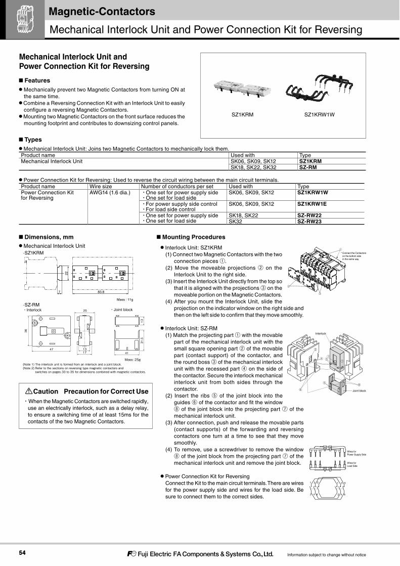
5454
Magnetic-Contactors
Information subject to change without notice
Mechanical Interlock Unit ·SZ1KRM
·SZ-RM
Interlock Unit: SZ1KRM(1) Connect two Magnetic Contactors with the two
connection pieces ①.(2) Move the moveable projections ② on the
Interlock Unit to the right side.(3) Insert the Interlock Unit directly from the top so
that it is aligned with the projections ③ on the moveable portion on the Magnetic Contactors.
(4) After you mount the Interlock Unit, slide the projection on the indicator window on the right side and then on the left side to confirm that they move smoothly.
Interlock Unit: SZ-RM(1) Match the projecting part ① with the movable
part of the mechanical interlock unit with the small square opening part ② of the movable part (contact support) of the contactor, and the round boss ③ of the mechanical interlock unit with the recessed part ④ on the side of the contactor. Secure the interlock mechanical interlock unit from both sides through the contactor.
(2) Insert the ribs ⑤ of the joint block into the guides ⑥ of the contactor and fit the window ⑧ of the joint block into the projecting part ⑦ of the mechanical interlock unit.
(3) After connection, push and release the movable parts (contact supports) of the forwarding and reversing contactors one turn at a time to see that they move smoothly.
(4) To remove, use a screwdriver to remove the window ⑧ of the joint block from the projecting part ⑦ of the mechanical interlock unit and remove the joint block.
Power Connection Kit for ReversingConnect the Kit to the main circuit terminals. There are wires for the power supply side and wires for the load side. Be sure to connect them to the correct sides.
Mechanical Interlock Unit: Joins two Magnetic Contactors to mechanically lock them.Product name Used with TypeMechanical Interlock Unit SK06, SK09, SK12 SZ1KRM
SK18, SK22, SK32 SZ-RM
Power Connection Kit for Reversing: Used to reverse the circuit wiring between the main circuit terminals.Product name Wire size Number of conductors per set Used with TypePower Connection Kit for Reversing
AWG14 (1.6 dia.) ・One set for power supply side・One set for load side
SK06, SK09, SK12 SZ1KRW1W
・For power supply side control・For load side control
SK06, SK09, SK12 SZ1KRW1E
・One set for power supply side・One set for load side
SK18, SK22 SZ-RW22SK32 SZ-RW23
①* Connect the Contactors on the bottom side in the same way.
②
③
Wires for Load Side
Wires for Power Supply Side
1 3 5
2 4 6
1 3 5
2 4 6
Features Mechanically prevent two Magnetic Contactors from turning ON at the same time.
Combine a Reversing Connection Kit with an Interlock Unit to easily configure a reversing Magnetic Contactors.
Mounting two Magnetic Contactors on the front surface reduces the mounting footprint and contributes to downsizing control panels.
Types
Dimensions, mm Mounting Procedures
Mechanical Interlock Unit and Power Connection Kit for Reversing
83.8
Mass : 11g
22
7
SZ1KRM SZ1KRW1W
・Interlock ・Joint block
(Note 1) The interlock unit is formed from an interlock and a joint block.(Note 2) Refer to the sections on reversing type magnetic contactors and switches on pages 33 to 35 for dimensions combined with magnetic contactors.
Mass: 25g
25
17 13 47
36
41
31.5
13
Joint block
Interlock
⑦
①
②
③④
⑤
⑥⑧
Mechanical Interlock Unit and Power Connection Kit for Reversing
Caution Precaution for Correct Use・When the Magnetic Contactors are switched rapidly,
use an electrically interlock, such as a delay relay, to ensure a switching time of at least 15ms for the contacts of the two Magnetic Contactors.
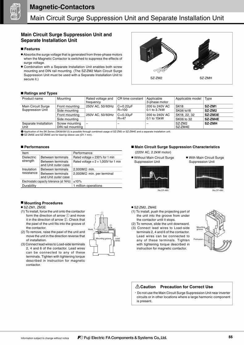
5555
Magnetic-Contactors
Information subject to change without notice
Product name Mounting Rated voltage and frequency
CR time constant Applicable 3-phase motor
Applicable model Type
Main Circuit Surge Suppression Unit
Front mounting 250V AC, 50/60Hz C=0.22μFR=100Ω
200 to 240V AC0.1 to 3.7kW
SK18 SZ-ZM1Side mounting SK06 to18 SZ-ZM2Front mounting 250V AC, 50/60Hz C=0.33μF
R=47Ω200 to 240V AC0.1 to 15kW
SK18, 22, 32 SZ-ZM3ESide mounting SK06 to 32 SZ-ZM4E
Separate Installation Unit
Screw mountingDIN rail mounting
– – – SZ-ZM2SZ-ZM4E
SZ-ZMH
❶ Application of the SK Series (SK06/09/12) is possible through combined usage of SZ-ZM2 or SZ-ZM4E and a separate installation unit.❷ SZ-ZM3E and SZ-ZM4E are for lead tip sleeve use (Ø1.1 mm).
Item PerformanceDielectric strength
Between terminals Rated voltage × 230% for 1 minBetween terminals and Unit outer case
Rated voltage × 2 + 1,000V for 1 min
Insulation resistance
Between terminals 2,000MΩ min.Between terminals and Unit outer case
2,000MΩ min. per terminal
Electrostatic capacity tolerance (at 1kHz) ±10%Durability 1 million operations
(220V AC, 2.2kW motor)
Caution Precaution for Correct Use・Do not use the Main Circuit Surge Suppression Unit near inverter
circuits or in other locations where a large harmonic component is present.
Features Absorbs the surge voltage that is generated from three-phase motors when the Magnetic Contactor is switched to suppress the effects of surge voltage.
Combination with a Separate Installation Unit enables both screw mounting and DIN rail mounting. (The SZ-ZM2 Main Circuit Surge Suppression Unit must be used with a Separate Installation Unit to secure it.)
Mounting Procedures SZ-ZM1, ZM3E
(1) To install, force the unit onto the contactor form the direction of arrow ① and move it in the direction of arrow ②. Check that the pawl of the unit fits into the groove of the contactor.
(2) To remove, raise the pawl of the unit and move the unit in the direction reverse that of installation.
(3) Connect lead wires to Load-side terminals 2, 4 and 6 of the contactor. Lead wires can be connected to any of these terminals. Tighten with tightening torque described in instruction for magnetic contactor.
SZ-ZM2, ZM4E(1) To install, push the projecting part of
the unit into the groove from under the contactor until it stops.
(2) To remove, slide the unit downward.(3) Connect lead wires to Load-side
terminals 2, 4 and 6 of the contactor. Lead wires can be connected to any of these terminals. Tighten with tightening torque described in instruction for magnetic contactor.
Ratings and Types
Performances Main Circuit Surge Suppression Characteristics
Without Main Circuit Surge Suppression Unit
With Main Circuit Surge Suppression Unit
Main Circuit Surge Suppression Unit and Separate Installation Unit
(No.CP-485) (No.CP-486)
SZ-ZM2 SZ-ZMH
Mounting groove
Hook
Lead wires
①
②
Protrusion
Mounting groove
Main Circuit Surge Suppression Unit and Separate Installation Unit

5656
Magnetic-Contactors
Information subject to change without notice
Dimension table
Type Dimension (mm)A B C
SK18A + SZ-ZM1 45 81 121SK18G + SZ-ZM1 45 81 134SK22A + SZ-ZM3E 45 81 121SK22G + SZ-ZM3E 45 81 134SK32A + SZ-ZM3E 53 81 121SK32G + SZ-ZM3E 53 81 134
Dimension table
Type Dimension (mm)A B C D
SK18A + SZ-ZM2 67 81 81 44.5SK18G + SZ-ZM2 67 81 94 44.5SK22A + SZ-ZM4E 67 81 81 44.5SK22G + SZ-ZM4E 67 81 94 44.5SK32A + SZ-ZM4E 75 81 81 44.5SK32G + SZ-ZM4E 75 81 94 44.5
Front mounting (SZ-ZM1, ZM3E)
Side mounting (SZ-ZM2, ZM4)
Separate installation unit (SZ-ZMH)
Mounting screw2×M4
85
47.4
75
28
12.4
46
57 (rail height: 15)
Wiring Diagram
Dimensions, mm
・Connection with magnetic starter
5
31
6
42
Magnetic contactor
Thermal overload relay
M
Motor
W
VU
Main circuit surge suppression unit
Mass: 60g45 43
27 344.
5
CA
B
Min. 5
Mass: 60g
22 60
39 37
Side-mounting face of magnetic contactor
CA
B
D
22
39
②Mounting groove
①Protrusion
MountingLine up protrusion ① on the side of the main circuit surge suppression unit with the mounting groove on the inner wall of the separate mounting unit, then press hard in the direction of the arrow until a click is heard.
(Note) SZ-ZM3E model is for lead tip sleeve use (Ø1.1 mm).
(Note 1) SZ-ZM4E model is for lead tip sleeve use (Ø1.1 mm). (Note 2) Side mounting-type main circuit surge suppression units can be mounted to either the left or right side of the magnetic contactor.
Main Circuit Surge Suppression Unit and Separate Installation Unit

5757
Magnetic-Contactors
Information subject to change without notice
Product name Surge suppression element
Specification Operation indicator lamp
Applicable model Control circuit voltage Type AC-operated type
DC-operated type
AC DC
Coil Surge Suppression Units
Varistor Varistor voltage: 100V - SK06ASK09ASK12A
- 24-48V Not required. ❶ SZ1KZ1Varistor voltage: 240V 48-125V SZ1KZ2Varistor voltage: 470V 100-250V SZ1KZ3Varistor voltage: 100V LED (red) 24-48V Not required. ❶ SZ1KZ4Varistor voltage: 240V 48-125V SZ1KZ5
Diode - - - SK06G, LSK09G, LSK12G, L
- 12-125V SZ1K26Operation Indicator Units
- - LED (red) SK06ASK09ASK12A
12-24V 12-24V SZ1KL124-48V 24-48V SZ1KL248-125V 48-125V SZ1KL3
Coil Surge Suppression Units
Varistor Varistor voltage: 100V - SK18ASK22ASK32A
- 24-48V Not required ❶ SZ-Z1Varistor voltage: 470V - 100-250V SZ-Z2Varistor voltage: 910V - 380-440V - ❷ SZ-Z3
CR 0.22μF, 22Ω - SK18GSK22GSK32G
24-48V 24-48V SZ-Z40.1μF, 220Ω - 100-250V 100-250V SZ-Z5
Varistor Varistor voltage: 100V LED (red) - 24-48V Not required ❶ SZ-Z6Varistor voltage: 470V LED (red) 100-250V SZ-Z7
CR 0.22μF, 22Ω LED (red) SK18GSK22GSK32G
24-48V 24-48V SZ-Z80.1μF, 220Ω LED (red) 100-250V 100-250V SZ-Z9
Note: ❶ A varistor is built into the SK□G and SK□L for DC operation.Note: ❷ This type of unit is used for AC-operated contactors only.
Features
The Main Circuit Surge Absorber Unit absorbs the surge voltage that is generated when the coil in a Magnetic Contactor turns OFF. This suppresses malfunctioning of electronic circuits.
The Operation Indicator Unit indicates with an LED when voltage is applied to the coil terminals.
Ratings and Types
Product Application Characteristics (200V AC coil)
Without Surge Suppression Unit
A sharp surge voltage is generated from the coil due to coil inductance as a result of the rapid change in voltage when the coil turns OFF. This becomes noise to surrounding electronic devices, and can cause malfunctions and circuit destruction.
SK12A
(0.1ms/div, 1kV/div)
Models with varistors built in
When the surge voltage reaches a certain level, current flows to the varistor that is connected in parallel with the coil. This serves to control the peak surge voltage.Varistors can be applied to either AC or DC.The suppressed surge voltage is approximately the varistor voltage.
SK12A + SZ1KZ3
(2ms/div, 200V/div)
Coil Surge Suppression Characteristics
Coil Surge Suppression Units and Operation Indicator Lamps
SZ1KZ3 SZ1KZ4
Coil Surge Suppression Units and Operation Indicator Lamps

5858
Magnetic-Contactors
Information subject to change without notice
Mounting methods
Dimensions, mm
SZ1KZ1 to 6, SZ1KL1 to 3(1) Insert the Unit into the mounting holes in the Magnetic Contactor.
The Unit must be oriented properly top to bottom. Do not mount the Unit backwards.
· Mounting to Non-reversing Magnetic Contactors
· Mounting to Reversing Magnetic Contactors
SZ-Z1 to Z9, SZ-Z31 to Z37, SZ-Z41 to Z45(1) Insert the terminals on the unit into coil terminals A1 and A2, then
press the protrusion for fixing the unit in place into the groove on the magnetic contactor main unit to mount it.Tighten the unit terminals along with the operating circuit electric wires.
+(DC)
-(DC)
+(DC)
-(DC)Protrusion Press the protrusion on the unit
into the groove on the main unit.
Surge suppression unit Coil terminal
SZ1KZ1 to SZ1KZ3 SZ1KZ623
6.5
Internal Connection Diagram
Mass : 3g3515
Internal Connection Diagram
Mass : 4g46.5
26.5
LED (red)
23
6.5
Internal Connection Diagram
Mass : 2g
LED (red)
3818
23
6.5
SZ1KZ1 to SZ1KZ3, SZ1KZ6 (Coil Surge Suppression Units)
SZ-Z1, Z2, Z3 (Varistor built-in type) SZ-Z4, Z5 (CR built-in type)
SZ-Z6, Z7 types (varistor built-in type, with LED indicator) SZ-Z8, Z9 types (CR built-in type, with LED indicator)
SZ1KZ4 and SZ1KZ5 (Coil Surge Suppression Units with Operation Indicator Lamps)
SZ1KL1 to SZ1KL3 (Operation Indicator Units)
2638
Internal Connection Diagram
Varistor built-in type
CR built-in type
Mass: 14g
CR
15
142.5
27
Internal Connection Diagram
Varistor built-in type
CR built-in type
Mass: 16g
LEDLED
R
R2
R1C
38 35
+ -
(Note 1) For DC operated units, pay careful attention to the polarity.
142.
51527
Coil Surge Suppression Units and Operation Indicator Lamps
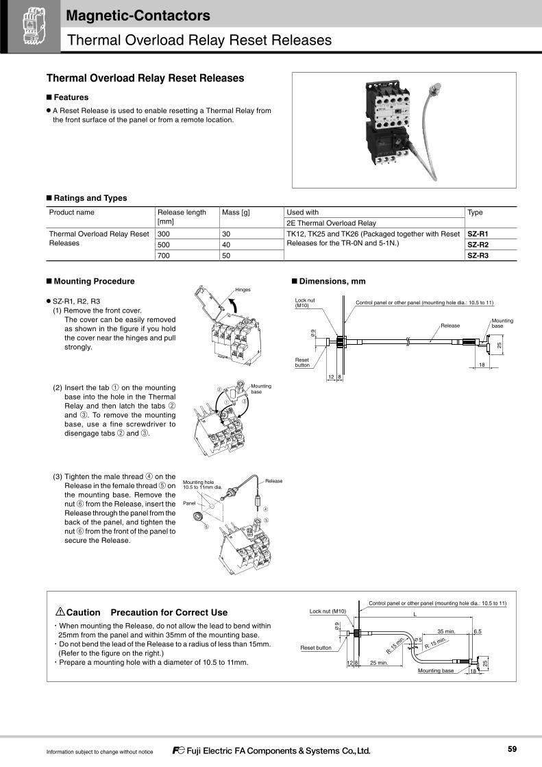
5959
Magnetic-Contactors
Information subject to change without notice
Caution Precaution for Correct Use・When mounting the Release, do not allow the lead to bend within
25mm from the panel and within 35mm of the mounting base.・Do not bend the lead of the Release to a radius of less than 15mm.
(Refer to the figure on the right.)・Prepare a mounting hole with a diameter of 10.5 to 11mm.
Product name Release length [mm]
Mass [g] Used with Type
2E Thermal Overload Relay
Thermal Overload Relay Reset Releases
300 30 TK12, TK25 and TK26 (Packaged together with Reset Releases for the TR-0N and 5-1N.)
SZ-R1500 40 SZ-R2700 50 SZ-R3
25
18
Control panel or other panel (mounting hole dia.: 10.5 to 11)
Mounting base
Lock nut (M10)
Reset button
L
35 min.
25 min.
R: 15 min.∅5
R: 15 m
in.6.5∅
9
812
18
25
12 8
∅9
Reset button
Lock nut (M10) Control panel or other panel (mounting hole dia.: 10.5 to 11)
ReleaseMounting base
Features
A Reset Release is used to enable resetting a Thermal Relay from the front surface of the panel or from a remote location.
Ratings and Types
Mounting Procedure Dimensions, mm
SZ-R1, R2, R3(1) Remove the front cover.
The cover can be easily removed as shown in the figure if you hold the cover near the hinges and pull strongly.
(2) Insert the tab ① on the mounting base into the hole in the Thermal Relay and then latch the tabs ② and ③. To remove the mounting base, use a fine screwdriver to disengage tabs ② and ③.
(3) Tighten the male thread ④ on the Release in the female thread ⑤ on the mounting base. Remove the nut ⑥ from the Release, insert the Release through the panel from the back of the panel, and tighten the nut ⑥ from the front of the panel to secure the Release.
Thermal Overload Relay Reset Releases
Hinges
Mountingbase②
① ③
⑤⑥
④
Release
Panel
Mounting hole 10.5 to 11mm dia.
Thermal Overload Relay Reset Releases

6060
Magnetic-Contactors
Information subject to change without notice
Separate Mounting Unit for Thermal Overload Relay
Features By combining this unit with a thermal overload relay for a magnetic starter, it can be used as a thermal overload relay for separate mounting.
Screw mounting and rail mounting using an IEC top hat type of rail (35 mm width) are available.
Ordering Information (Types) Separate Mounting Unit for Thermal Overload Relay
Mounting Procedure(1) Fully loosen the terminal screws of the separate mounting unit.(2) Insert the connecting wires of the thermal overload relay, along the insertion guide of the separate mounting unit (Figure 1).(3) Press the thermal overload relay in the direction of the arrow, and confirm that the lower section of the thermal overload relay is securely
engaged with the hooks (2 locations) of the separate mounting unit (Figure 2).
Separate Mounting Unit for Thermal Overload Relay
TZ1H26N
TZ1H26N
① Type
Note: An order can also be made with the product type code.
Product name Applicable thermal overload relay
Type
Separate Mounting Unit for Thermal Overload Relay
TK12 TZ1H12NTK26 TZ1H26N
Types
Connecting wire of thermal overload relay
Insertion guide
Figure 1
Hooks (2 locations)
Hook
Figure 2
Click

6161
SK SeriesMagnetic-Contactors
Information subject to change without notice
Dimensions
Mass: 30g
Mass: 40g
・Dimension for mounting: 35 x 60
・Mounting screw: 2-M4
・Dimension for mounting: 35 x 60
・Mounting screw: 2-M4
TZ1H12N
35mm
TZ1H26N
35mm 84.5 (for rail height: 7.5)92 (for rail height: 15)
7.5
57
35
81.5
66
M4Main terminals
51
17.213
9.7
9.7
76
2-M4Mounting hole
11
1035
60
5L33L21L1
45
7.535
9
5
60
35
45
65 (for rail height: 7.5)72.5 (for rail height: 15)
62
46.5
9
22
7.7
74
8.8
Main terminalsM3.5
2-M4Mounting hole
Mounting Hole Dimensions
Mounting Hole Dimensions
5L33L21L1

6262
Magnetic-Contactors
Information subject to change without notice
Link Module/Spacer : Electrically and mechanically connects a Manual Motor Starter and Magnetic Contactor.Link Module (for SK06, SK09, SK12)
Photo No. KKD11-101
Applicable MMS Applicable Magnetic Contactors Type
BM3RSBBM3RHB
SK06, SK09, and SK12 BZ0LRK12AA
Link Module (for SK18, SK22)
NEW
Photo No. KKD15-219
BM3RSBBM3RHBBM3RSRBM3RHR
SK18A, SK18GSK22A, SK22G
BZ0LRK22AA
Link Module (for SK32 type)
NEW
Photo No. KKD15-221
SK32A, SK32G BZ0LRK32AA
Spacer (for SK18A, SK22A, SK32A)
NEW
Photo No. KKD15-223
- SK18ASK22ASK32A
BZ0LRKACA
Power Connection Kit for Reversing (Insert): Used to reverse the circuit wiring between the main circuit terminals.
Photo No. KKD11-113
Wire size Number of conductors per set Applicable MMS Applicable types Type
1.6 dia. ・One set for power supply side・One set for load side
BM3RSBBM3RHB
SK06, SK09, and SK12 SZ1KRW1M
Features
Connect a Manual Motor Starter and a Magnetic Contactor directly through a Link Module.
A Reversing Connection Kit (Insert) for Combination Starters has joined the lineup.
Types
Link Module and Power Connection Kit for Reversing (Insert)
BZ0LRK12AA SZ1KRW1M
Link Module and Power Connection Kit for Reversing (Insert)
Combination Starter Configuration Table
Applicable MMS Applicable magnetic contactor Link module SpacerOperating coil
BM3RSB
BM3RHB
SK06A, SK06G, SK06L
SK09A, SK09G, SK09L
SK12A, SK12G, SK12L
AC
DC
BZ0LRK12AA −
BM3RSRBM3RHR SK18A AC *1 BZ0LRK22AA BZ0LRKACA
SK22ASK18G DC −SK22GSK32A AC *1 BZ0LRK32AA BZ0LRKACASK32G DC
*1 For an AC coil product (AC-operated type), a spacer is necessary besides a link module.Note: When combining with SK18, SK22 or SK32 types, you can use only an MMS with the changed slider. When ordering an MMS with the changed slider, please order this item with "NEW" appended to the product type code.

6363
SK SeriesMagnetic-Contactors
Information subject to change without notice
14.6
52.2
46.2
8.5
11.3
37.9
8.78.7
∅1.614.514.531
2-∅6.4
58.6
35
63.3
44.4
Mass : 25g
Dimensions, mm
Link Module BZ0LRK12AA
Link Module BZ0LRK32AA
Link Module BZ0LRK22AA
Spacer BZ0LRKACA
62.9
45.5
28.1
8484
62.9
Mass : 17g Mass : 13g
45.5
28.1
The dotted line indicates wiring for an electrical interlock when the integrated auxiliary
contact is 1NC x 2. When the integrated auxiliary contact is 1NO x 2 or when wiring is
not necessary, only the main circuit should be used by separating this section.
Power Connection Kit for Reversing (Insert) SZKRW1H
[Insert for Power Supply Side] [Insert for Load Side]
30.93
79.2
73.7
54.
2
45.
4
10.4
10.9
17.45.3
Ø214.3
45
14.3
Mass: 35g
47
10.4
30.6
3
54.2 45
.4
2
80.2
74
10.9
3.1
1313
Ø2.614.314.3
Mass: 41g
45
6935
35
60
2-Ø5.2
17.3
12.3
Mass: 20g

6464
Magnetic-Contactors
Information subject to change without notice
SKH4 A H - E 22① ② ③ ④ ⑤
Operating coil specification②
Contact specification③
Coil voltage specification④
Contact arrengement⑤
Type
AC-operated types[A]
Bifurcated contact[blank]
24V [E] 120V [K] 380V [S] 4NO SKH4A-□40
48V [F] 200V [2] 400V [4] 3NO+1NC SKH4A-□31
100V [1] 220V [M] 440V [T] 2NO+2NC SKH4A-□22
Single button contact[H]
110V [H] 240V [P] 500V [5] 4NO SKH4AH-□40
3NO+1NC SKH4AH-□31
2NO+2NC SKH4AH-□22
DC-operated types (2.4W)[G]
Bifurcated contact[blank]
12V [B] 100V [1] 210V [Y] 4NO SKH4G-□40
24V [E] 110V [H] 220V [M] 3NO+1NC SKH4G-□31
48V [F] 120V [K] 2NO+2NC SKH4G-□22
Single button contact[H]
60V [G] 200V [2] 4NO SKH4GH-□40
3NO+1NC SKH4GH-□31
2NO+2NC SKH4GH-□22
DC-operated types (1.2W)[L]
Bifurcated contact[blank]
12V [B] 4NO SKH4L-□40
24V [E] 3NO+1NC SKH4L-□31
48V [F] 2NO+2NC SKH4L-□22
Single button contact[H]
4NO SKH4LH-□40
3NO+1NC SKH4LH-□31
2NO+2NC SKH4LH-□22
Note. “□” in the type column is replaced with the coil voltage code.
①Series ②Operating coil ③Contact specification ④Coil voltage specification ⑤Contact arrengement
Features International safety standards for standard models (IEC, GB, JIS, UL, and CSA).
Models available with AC, DC, or low-power DC operating coils. Bifurcated contact for more reliable contact for micro-loads of 3mA at 5V DC.
Models with high-capacity contacts (single button contact) are also available.
Configure a wide range of contacts in combination with Auxiliary Contact Blocks.
RatingsRefer to Auxiliary Contact Ratings on page 11.
Ordering Information (Types)
Types
Auxiliary Relays
SKH4A
Auxiliary Relays

6565
SK SeriesMagnetic-Contactors
Information subject to change without notice
Durability (Based on IEC 60947-5-1)Type Number of
contactsOperating cycles per hour [times/hour]
Mechanical durability
Electrical durability
AC-15 AC-12 DC-13 DC-12
220V 440V 220V 440V 220V 220V
SKH4 4 1800 10 million 500,000 500,000 250,000 250,000 250,000 500,000
SK-Series Auxiliary Relays and Auxiliary Contacts Blocks can be combined as shown in the following table. Other combinations are not possible.
Auxiliary ContactBlock
Auxiliary Relay type
Type SZ1KA40SZ1KA40H
SZ1KA31SZ1KA31H
SZ1KA22SZ1KA22H
SZ1KA13SZ1KA13H
SZ1KA04SZ1KA04H
SZ1KA20SZ1KA20H
SZ1KA11SZ1KA11H
SZ1KA02SZ1KA02H
SZ1FA11SZ1FA11H
Auxiliary contact arrangement
4NO 3NO+1NC 2NO+2NC 1NO+3NC 4NC 2NO 1NO+1NC 2NC 1NO+1NC
Combined auxiliary contact arrangement
SKH4A SKH4AHSKH4G SKH4GH
4NO 8NO 7NO+1NC 6NC+2NC 5NO+3NC 4NO+4NC 6NO 5NO+1NC 4NO+2NC 5NO+1NC
3NO+1NC 7NO+1NC 6NO+2NC 5NO+3NC 4NO+4NC 3NO+5NC 5NO+1NC 4NO+2NC 3NO+3NC 4NO+2NC
2NO+2NC 6NO+2NC 5NO+3NC 4NO+4NC 3NO+5NC 2NO+6NC 4NO+2NC 3NO+3NC 2NO+4NC 3NO+3NC
SKH4L SKH4LH 4NO − − − − − 6NO 5NO+1NC 4NO+2NC 5NO+1NC
3NO+1NC − − − − − 5NO+1NC 4NO+2NC 3NO+3NC 4NO+2NC
2NO+2NC − − − − − 4NO+4NC 3NO+3NC 2NO+4NC 3NO+3NC
Auxiliary Contact BlockAuxiliary Relay type
No Auxiliary Contact Block SZ1KA□ SZ1FA11 SZ1KA□H SZ1FA11H
4-pole 2-pole 4-pole 2-pole
SKH4A SKH4AH ◯ × × × × × ×
SKH4G SKH4GH ◯ × × ◯ ◯ ◯ ◯SKH4L SKH4LH ◯ − ◯ ◯ − ◯ ◯
◯ : Complies. × : Does not comply.
SKH4
(34) *1
(17)*22-M4 mounting holes6
40
35
Coil terminal M3.5
Terminal M3.5
61 (rail height: 15)
36
49
7.7
48 31
45
8.7
34
33
A2 (-)
A1 (+)
※
13 21 31 43
322214 44
※2NO+2NC
4414 22
432113
※For DC-operated types.Mass : 0.14kg (SKH4A) 0.17kg (SKH4G and SKH4L)
[NOTE]*1: With SZ1KA□ Auxiliary Contact Blocks.*2: With SZ1FA□ Auxiliary Contact Blocks.
※
※
※
※
※
※
A1 (+)
A2 (-)
Mounting screws: 2-M4 screwsMount the Auxiliary Relay with two mounting holes in diagonally opposed corners.
44
43332313
14 24 34
Auxiliary contacts
Contact arrangement
4NO
3NO+1NC
A2 (-)
A1 (+)
Mounting Hole Dimensions
-A244322214
+A1NO43NC31NC2113 NO
Performances
Combinations with Auxiliary Contact Blocks
Linked Contact Compliance (Compliance with Requirements of IEC60947-5-1 Annex L)
Dimensions, mm

6666
Magnetic-Contactors
Information subject to change without notice
MEMO

Magnetic-Contactors
Information in this catalog is subject to change without notice.
5-7, Nihonbashi Odemma-cho, Chuo-ku, Tokyo, 103-0011, Japan
URL http://www.fujielectric.co.jp/fcs/eng
Safety Considerations• Operate (keep) in the environment specified in the operating instructions and manual. High temperature, high humidity, condensation, dust,
corrosive gases, oil, organic solvents, excessive vibration or shock might cause electric shock, fire, erratic operation or failure.• For safe operation, before using the product read the instruction manual or user manual that comes with the product carefully or consult the
Fuji sales representative from which you purchased the product.• Products introduced in this catalog have not been designed or manufactured for such applications in a system or equipment that will affect
human bodies or lives.• Customers, who want to use the products introduced in this catalog for special systems or devices such as for atomic-energy control,
aerospace use, medical use, passenger vehicle, and traffic control, are requested to consult with Fuji Electric FA.• Customers are requested to prepare safety measures when they apply the products introduced in this catalog to such systems or facilities
that will affect human lives or cause severe damage to property if the products become faulty.• For safe operation, wiring should be conducted only by qualified engineers who have sufficient technical knowledge about electrical work or
wiring.• Follow the regulations of industrial wastes when the product is to be discarded.• For further questions, please contact your Fuji sales representative or Fuji Electric FA.
2017-2 PDF FOLS 62C1-E-0022b