… magnesium alloys are environmentally friendly, … · Web view2005/06/19 · Magnesium alloys...
42
BRAZING OF MAGNESIUM ALLOYS AND MAGNESIUM MATRIX COMPOSITES FOR AUTOMOTIVE AND AEROSPACE APPLICATIONS Alexander E. Shapiro INTRODUCTION Methods, filler metals, and fluxes suitable for brazing of cast and extruded magnesium-based alloys were well developed in 1960-s and 1970-s. Since that time, the furnace, torch, and dip brazing processes are successfully employed without considerable changes. New interest to brazing magnesium has been recently aroused due to the expansion of use of magnesium alloys in 1990-s, and especially, due to an appearance of high-strength magnesium matrix composites as lightweight advanced structural materials for automotive and aerospace. Magnesium alloys are considered as possible replacements for aluminum, plastics, and steels, primarily because of their higher ductility, greater toughness, and better castability. Production of magnesium was almost tripled last decade, and the world production capacity reached 515 thousand tons per year in 2002, including 250 thousand t/year in the Western World, 150 thousand t/year in China, and 65 thousand t/year in countries of former Soviet Union (Ref. 1). Both big volume of magnesium production and applications of new high-performance magnesium alloys that came up in the world market cause a scientific and technical challenge to the brazing engineering community. This paper (a) summarizes the experience in joining of cast, extruded, and rolled magnesium alloys, (b) evaluates the potential of conventional brazing technologies for improving mechanical properties and corrosion resistance of joints, and (c) discusses new developments to be done to response industrial demand in joining of new advanced cast or rolled magnesium alloys and magnesium matrix composites reinforced with carbon or ceramic fibers and particles. CHARACTERIZATION AND BRAZEABILITY OF BASE METALS 1
Transcript of … magnesium alloys are environmentally friendly, … · Web view2005/06/19 · Magnesium alloys...

BRAZING OF MAGNESIUM ALLOYS AND MAGNESIUM MATRIX COMPOSITES FOR AUTOMOTIVE
AND AEROSPACE APPLICATIONS
Alexander E. Shapiro
INTRODUCTION
Methods, filler metals, and fluxes suitable for brazing of cast and extruded magnesium-based alloys
were well developed in 1960-s and 1970-s. Since that time, the furnace, torch, and dip brazing processes
are successfully employed without considerable changes. New interest to brazing magnesium has been
recently aroused due to the expansion of use of magnesium alloys in 1990-s, and especially, due to an
appearance of high-strength magnesium matrix composites as lightweight advanced structural materials
for automotive and aerospace. Magnesium alloys are considered as possible replacements for aluminum,
plastics, and steels, primarily because of their higher ductility, greater toughness, and better castability.
Production of magnesium was almost tripled last decade, and the world production capacity reached 515
thousand tons per year in 2002, including 250 thousand t/year in the Western World, 150 thousand t/year
in China, and 65 thousand t/year in countries of former Soviet Union (Ref. 1). Both big volume of
magnesium production and applications of new high-performance magnesium alloys that came up in the
world market cause a scientific and technical challenge to the brazing engineering community.
This paper (a) summarizes the experience in joining of cast, extruded, and rolled magnesium alloys,
(b) evaluates the potential of conventional brazing technologies for improving mechanical properties and
corrosion resistance of joints, and (c) discusses new developments to be done to response industrial
demand in joining of new advanced cast or rolled magnesium alloys and magnesium matrix composites
reinforced with carbon or ceramic fibers and particles.
CHARACTERIZATION AND BRAZEABILITY OF BASE METALS
Magnesium is the lightest and one of the cheapest structural metal. Magnesium alloys are
environmentally friendly, lighter than aluminum (only 2/3 of aluminum and 1/3 of titanium specific
weights), better in heat dissipation and heat transfer due to high thermal conductivity of 51 W/mK, and
exhibit excellent ability in shielding electromagnetic interrupt. Low density ~1.75 g/cm3 in the combination
with relatively high tensile strength 33-42 ksi (228-290 MPa), heat resistance up to 840 oF (450oC), and
oxidation resistance up to 930oF (500oC) make magnesium alloys attractive for application in various
structures in automotive, and especially, aerospace industry, as well as in textile and printing machines
where lightweight magnesium parts are used to minimize inertial forces when they operate at high speed
(Ref. 2). Moreover, the use of magnesium can minimize the negative impact on the environment because
_______________________
Alexander E. Shapiro is with Titanium Brazing, Inc., Columbus, OH
1

magnesium alloys are recyclable. However, the surface of magnesium alloys should be protected
because they corrode easily when exposed to atmosphere.
A significant growth in the production and applications of structural magnesium alloys has been seen
past two decades. The demand is driven primarily by automotive and aerospace industries to reduce
weight and fuel consumption (Ref. 3). Conventional magnesium alloys are strength-competitive not only
with aluminum alloys but also with steels and titanium alloys. For example, a specific tensile strength (a
ratio of the strength to density) of hardened cast magnesium alloy HK31A is the same as this of standard
titanium alloy Ti-6Al-4V, hardened aluminum alloy AA7075, or steel AISI 4340. The specific strength of
extruded magnesium alloy AZ31B is higher than this of aluminum alloys AA6061 and AA3003, or carbon
steel AISI 1015 (Ref. 4).
Compositions, physical properties, and typical mechanical properties of brazeable magnesium alloys
are presented in Table 1 and 2. Because of their low solidus temperatures, some magnesium alloys
cannot be brazed with commercial brazing filler metals BMg-1 and BMg-2a and require the application of
other filler metals of the Mg-Al-Zn system having lower brazing temperature range.
Table 2
Typical mechanical properties of brazeable magnesium alloys at room temperature
ASTM Alloy Designation
Yield strength Tensile strengthElongati
on, %
Young’s Modulus
MPa ksi MPa ksi GPa 103 ksiM1A 138 20 234 34 9.0 45.0 6.5
AZ31B 170 25 260 38 15.0 45.0 6.5
AZ61A 205 30 305 44 16.0 45.0 6.5
AZ63A 130 19 275 40 6.0-12.0 45.0 6.5
AZ91C 145 21 225 33 6.0 42.7 6.2
AS41A 140 20 215 31 6.0 - 9.0 45.0 6.5
AM100 110 16 230 33 2.0 45.0 6.5
ZE10A 179 26 255 37 12.0 45.0 6.5
ZK21A 228 33 290 42 10.0 45.0 6.5
ZK51A 131 19 205 30 3.5 43.2 6.3
ZK60A 285 41 350 51 11.0 45.0 6.5
QE22A 195 28 260 38 3.0 - 4.5 46.0 6.7
QH21A 186 27 241 35 2.0 46.0 6.7
HK31A 112 16 225 33 9.5 46.0 6.7
ZC71 342 47 360 52 3.0 – 5.0 43.5 6.4
2

The temperatures involved in brazing reduce the properties of work-hardened (tempered)
magnesium sheet alloys to the annealed temper level. For example, the extruded and tempered alloy
AZ31B looses about 35% of elongation, 22% of yield strength, and 8% of tensile strength after brazing at
595oC (1102oF) for 1-2 min (Ref. 5, 6). A significant loss of mechanical properties is the main motivation
to develop and implement low-melting brazing filler metals.
Torch brazing reduces properties of base metals only locally, in those areas heated for brazing;
furnace and dip brazing reduce properties of the entire structure. The properties of cast alloys or of
annealed sheet alloys are not greatly affected by the heat of brazing.
Magnesium alloys with reduced aluminum content AM60, AM50, and AM20 are suitable for
applications requiring improved fracture toughness and ability to absorb energy without failure. However,
the reduced amounts of aluminum result in slight decrease in strength of AM alloys (Ref. 7). Alloys AS41,
AS21, and AE42 can be employed for applications involving with long term exposure at temperatures
over 250oF (120oC) and requiring creep resistance.
Mechanical properties (especially plasticity) of magnesium alloys depend on the fabrication
parameters and the testing temperature. For example, a considerable change in mechanical properties of
the alloy AZ31 fabricated by casting, extrusion, and rolling was indicated (Ref. 8). The strength weakening
is accompanied with a remarcable increase in ductility: the elongation is increased from 21.5% to 66.5%
as the test temperature is changed from RT to 482oF (250oC).
Brazing of magnesium is not simple process due to the highest chemical activity among all structural
metals. Complex oxide film containing magnesium oxide and magnesium hydroxide is formed on the
surface of base metal at heating in air. This chemically-stable film is not reduced neither in conventional
active gaseous atmospheres nor in vacuum up to 10 -5 mm-Hg (10-5 Torr). Additionally, magnesium
hydroxide is decomposed to hydrogen and water during the heating at 572-752oF (300-400oC), that
further hinders the brazing process (Ref. 9).
Density of magnesium filler metals is less than density of salt systems used as brazing fluxes that
often results in appearance of slag inclusions in the joints. Also, magnesium has high negative value of
the electrode potential (-2.38 V) that hinders deposition of reliable electrolytic or chemical coatings that
could improve wetting by molten brazing filler metals or protect against the flux corrosion. Risk factors and
methods of preventing defects in magnesium brazing are presented in Table 3.
Magnesium matrix composites (MMC) reinforced with ceramics and graphite fibers or particles
present a new class of ultra-lightweight structural materials joined by brazing. These base metals are
ideal for aerospace applications owing to their high strength and stiffness, good thermal and electrical
conductivity, and resistance to space environment. Continuously reinforced, thin-walled metal matrix
parts are particularly used in spacecrafts as stiff, dimensionally-stable structural members. Thinner parts
permit more efficient design resulting in reduced weight and increased payload. Also, continuous fiber
reinforcement allows design of zero thermal expansion structures to obtain dimensional stability over wide
temperature range and accurate pointing angles for reflectors and antennae (Ref. 10).
3
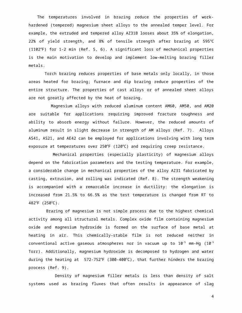
Table 3
Technical problems in magnesium brazing
Problems Possible negative effect Technical solution
Chemical activity of base metal.Fast growth of oxide film [MgO + Mg(OH)2]
Difficult wetting by brazing filler metal
Halide brazing fluxes.Vacuum brazing at <10-5 Torr.Brazing in dry argon.
Low solidus of base metals.Brazing temperature is close to solidus.
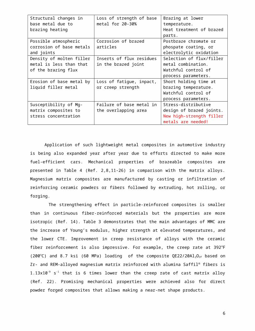
Changes in structure and shape of brazed parts
Short holding time at brazing temperature.Low-temperature filler metals are needed!
Structural changes in base metal due to brazing heating
Loss of strength of base metal for 20-30%
Brazing at lower temperature.Heat treatment of brazed parts.
Possible atmospheric corrosion of base metals and joints
Corrosion of brazed articles Postbraze chromate or phospate coating, or electrolytic oxidation
Density of molten filler metal is less than that of the brazing flux
Inserts of flux residues in the brazed joint
Selection of flux/filler metal combination.Watchful control of process parameters.
Erosion of base metal by liquid filler metal
Loss of fatigue, inpact, or creep strength
Short holding time at brazing temperature.Watchful control of process parameters.
Susceptibility of Mg-matrix composites to stress concentration
Failure of base metal in the overlapping area
Stress-distributive design of brazed joints.New high-strength filler metals are needed!
Application of such lightweight metal composites in automotive industry is being also expanded year
after year due to efforts directed to make more fuel-efficient cars. Mechanical properties of brazeable
composites are presented in Table 4 (Ref. 2,8,11-26) in comparison with the matrix alloys. Magnesium
matrix composites are manufactured by casting or infiltration of reinforcing ceramic powders or fibers
followed by extruding, hot rolling, or forging.
The strengthening effect in particle-reinforced composites is smaller than in continuous fiber-
reinforced materials but the properties are more isotropic (Ref. 14). Table 3 demonstrates that the main
advantages of MMC are the increase of Young’s modulus, higher strength at elevated temperatures, and
the lower CTE. Improvement in creep resistance of alloys with the ceramic fiber reinforcement is also
impressive. For example, the creep rate at 392oF (200oC) and 8.7 ksi (60 MPa) loading of the composite
QE22/20Al2O3f based on Zr- and REM-alloyed magnesium matrix reinforced with alumina Saffil fibers is
1.13x10⁻⁹ s-1 that is 6 times lower than the creep rate of cast matrix alloy (Ref. 22). Promising mechanical
properties were achieved also for direct powder forged composites that allows making a near-net shape
products.
4

Table 4Mechanical Properties of Magnesium Matrix Alloys and Their Composites Reinforced with SiC,
SiO2, TiC or Al18B4O33 particles, and SiC, Al2O3 or graphite fibers
Matrix alloysand composites
(vol.%)
Yield strength Tensile strengthElongation,
%
Young’s ModulusMPa ksi MPa ksi GPa 103 ksi
AZ91C – matrix 145 21 225 33 7.2 42.7 6.2AZ91C/15SiCp * 178 26 218 32 1.1 57.0 9.2AZ91C/10TiCp * - 214 31 4.0 52.0 7.5AZ91C/30Al2O3 f * 230 33 280 40 1.8 64.0 9.3AZ91/30Graphite f * - 350 51 - 70.0 10.1Mg1Al/60Graphite f - 1470 213 - 155.0 22.4ZK51A – matrix 131 19 221 32 7.3 43.2 6.3ZK51A/15SiCp * 162 23 210 30 1.8 52.4 7.6ZC71 – matrix 340 49 360 52 5.0 -ZC71/12SiCp ** 397 57 453 66 1.0 -AM100 – matrix 110 16 230 33 2.0 45.0 6.5AM100/20Al2O3 f * - 220 32 1.5 75.0 10.9AS41 – matrix 125 18 193 28 9.0 50.0 7.3AS41/30Al2O3 f * 240 35 270 39 1.0 78.0 11.3AZ31B - matrix 170 25 260 38 15 -AZ31B/4SiO2 p** 229 33 314 45 4.4 -AZ31B/8SiO2 p** 260 38 330 48 6.0 -AZ31B/10SiC f **** 314 46 368 53 1.6 69.0 10.0AZ31B/20SiC f **** 417 60 447 65 0.9 100.0 14.5QE22 – matrix 180 26 250 36 4.5 46.0 6.7QE22/30Al2O3 f * 250 36 300 43 1.6 74.0 10.7QE22/25SiCp** 245 36 325 47 4.0 73.0 10.6Mg/10Mg2Sip *** - 175 25 - 55.0 8.0Mg/10Mg2Nip *** 117 17 202 29 3.6 -AZ91/10Al18B4O33* 266 38 480 70 1.0 78.0 11.3MB15/30Al18B4O33* 230 33 303 44 0.5 76.0 11.0Mg14Li1Al/30steelf * - 758 110 - 66.0 9.5Mg14Li1Al/30B p** 244 35 - - 101.0 14.6
* Casting; ** Forging; *** Undirectional solidification; **** ExtrusionFootnotes: p – particles, f - fibers
5
Some magnesium matrix composites exhibit impressive increase in mechanical performance in
contrast with non-reinforced matrix alloys. For example, the composite consisting of Mg-14Li-1Al matrix
and 30 vol.% of steel fibers has tensile strength 600-700 MPa (87-123 ksi) at room temperature and 450-
480 MPa (65-69 ksi) at 200oC (392oF), while the matrix alloy exhibits only 144 MPa (21 ksi)at room
temperature, and 14 MPa (2 ksi) at 200oC (Ref. 26).
The advanced Mg-based materials have great potential to improve mechanical performance in the
near future. New non-traditional reinforcing systems allow to reach strength characteristics of magnesium
matrix composites comparable with some steels or titanium alloys. For instance, the squeeze-casting
composite of the matrix AZ91D alloy reinforced with 10 vol.% of Al18B4O33 particles exhibits a tensile
strength 480 MPa (70 ksi) (Ref. 20). Even the low-alloyed magnesium matrix MB15 reinforced with 30 vol.
% of Al18B4O33 whiskers demonstrates a yield strength of 230 MPa (33 ksi) at very good rigidity
characterized with Young’s modulus 11 Mpsi (76 GPa) and elongation 0.5% (Ref. 21). An increase of
volume fraction of the reinforcing component can result in drastic change of mechanical properties. The
Switzerland company EMPA reported recently about the super-strength composite MgAl1/T300
containing 60 vol.% of graphite fibers (Ref. 25). This material exhibited tensile strength of 213 ksi (1470
MPa) and Young’s modulus 22.4 Mpsi (155 GPa).
Magnesium matrix composites are also prospective as high-damping materials used to reduce
mechanical vibrations. For example, undirectional solidification of Mg-2Si alloy yields Mg/Mg2Si composite
structure with a mechanical strength as high as the industrial cast alloy AZ63 but with a damping capacity
100 times higher (Ref. 19). A similar Mg-10Ni alloy with Mg/Mg2Ni structure provides a damping capacity
40 times higher than that of AZ63 cast. Moreover, Mg-2Si alloy reinforced with long carbon fibers has a
Young’s modulus of ~200 GPa with a damping capacity of 0.01 for strain amplitude of 10-5.
Due to low solidus limitation of the matrix, only low-temperature filler metals such as P380Mg and
P430Mg can be used for joining casting composites based on ZK51A and QE22A matrix alloys, or forged
composites based on ZK60A and ZC71 matrix alloys. Joining of other casting or forged composites can
be performed by placing filler metal GA432 or P380Mg between brazed parts and heating to 734-752 oF
(390-400oC) with thorough control of temperature. Joining of wrought magnesium composites based on
Mg-Zn matrixes is preferably carried out by soldering with Zn-Al solders.
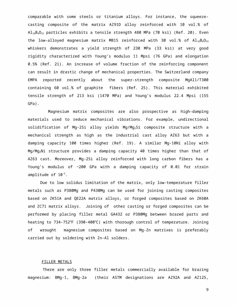
FILLER METALS
There are only three filler metals commercially available for brazing magnesium: BMg-1, BMg-2a
(their ASTM designations are AZ92A and AZ125, respectively) and MC3 alloy. The nominal compositions
and physical properties of these alloys are shown in Table 5. The standard filler metal MC3, used in
Japan, has the composition close to BMg-1. All three alloys are suitable for torch, furnace, or dip brazing
processes.
If torch or dip brazing are to be done at lower temperature, other filler metals showed in Table 6 (Ref.
5,9,27) can be used with appropriate testing of mechanical and corrosion properties of brazed joints.
Alloying elements such as Al, Zn, Mn, Be, Si, Zr, Ca, Ag, Th, Y, and Rare-earth metals (REM) have
effect on properties of magnesium-based filler metal somewhat similar to their effect on properties of die-
cast magnesium alloys.
6

Aluminum increases room temperature strength and hardness, and improves fluidity. However,
excessive aluminum amounts cause a decrease in ductility due to formation of brittle intermetallic phases.
Also, aluminum widens solidus-liquidus range. Zinc generally improves fluidity and strength of
magnesium alloys through solid-solution strengthening; but high levels of >2 wt.% of Zn can cause hot
cracking (Ref. 28). Zinc is also useful to prevent corrosion caused by Fe or Ni impurities in magnesium
alloys. Magnesium filler metals containing zinc in combination with zirconium or rare-earths can be
precipitation-hardened to increase the strength. However, zinc may not deteriorate hot cracking
resistance in combination with aluminum and manganese. For example, the cast alloy AZ88 (Mg-8Al-8Zn-
0.2Mn) exhibits sufficient resistant to hot cracking, yet retaining exceptional fluidity (Ref. 29). Small
additions of manganese do not affect mechanical properties, but they do produce beneficial effect in the
control of corrosion, especially in saltwater. The filler metals are alloyed with 0.1-0.5 wt.% of Mn to
improve corrosion resistance. In presence of aluminum, the solubility of Mn in solid solutions of
magnesium alloys is less than 0.3 wt.%. Cadmium is the only one metal which crystal lattice is fully
compatiblewith magnesium, but the most important fact is that cadmium forms solid solutions with
magnesium at any concentrations.
Beryllium is added in amounts of <0.002 wt.% to suppress excessive oxidation of molten metal and
to reduce risk of ignition during the torch brazing. Silicon improves fluidity of magnesium alloys in molten
state. Also, silicon is present in some alloys such as AS21 and AS41 to improve creep strength due to
formation of the reinforcing Mg2Si phase. The same effect of silicon can be expected in the filler metal
compositions that should be checked in future developments. However, silicon affects corrosion
resistance in presence of iron impurity. Silver makes possible age hardening that results in higher
strength both casting and wrought magnesium alloys. Rare-earth metal additions in amount of 2-4 wt.%
(for example, mishmetal containing 55 wt.% of Ce, 20 wt.% of La, 20 wt.% of Nd, and 5 wt.% of Pr)
produce stable grain-boundary precipitates that improve creep strength. Yttrium has high solubility in
magnesium – up to 12.4 wt.%. Yttrium and zirconium additions promote creep resistance of cast
magnesium alloys being added in the amounts up to 4 wt.% and up to 0.7 wt.%, respectively. Also,
zirconium is effective grain refiner in magnesium alloys because lattice parameters of α-Zr are very close
to those of magnesium. But, zirconium is not used in alloys containing both Al and Mn, which form
intermetallics with zirconium and remove it from solid solutions.
The corrosion rate increased abruptly with the addition of >1 wt.% of calcium. The negative effect of
Ca can be distinguished by adding zinc or rare-earth metals. Recent investigations demonstrated positive
effect of calcium on creep resistance of magnesium alloys. Calcium is not recommended for magnesium
alloys to be welded due to cracking but it is harmless for brazable alloys. Strontium up to 2 wt.%
improves fluidity of Mg-Al-Mn alloys without affecting corrosion resistance (Ref. 30). Lithium is the only
one alloying metal that decrease density of magnesium alloys. Solubility of Li in solid magnesium
solutions is as high as 5.5 wt.%, and lithium can be added up to this amount to improve ductility of the
alloys, but it may cause decreasing of strength. Tin is added to magnesium in combination with aluminum
to improve ductility and reduce tendency to hot cracking. Thorium in amount of 1-3 wt.% is very effective
to improve creep resistance of magnesium alloys, especially in combination with REM.
7

The following elements of IVA and VA groups: Si, Ge, Pb, Sb, and Bi form stable intermetallic phases
with magnesium (Ref. 31) and can be used as alloying components for precipitation strengthening Mg-Al-
based filler metals.
Preparation of brazing filler metals always includes melting of magnesium followed by dissolution
alloying metals in the melt. Liquid solubility of alloying metals in magnesium is shown in Table 7 .
Table 7
Liquid solubility of alloying elements in magnesium melt
Alloying element
Metal or master-alloy
Apparent liquid
solubility, %
Alloying element
Metal or master-alloy
Apparent liquid
solubility, %Ag, Al, Au, Ba,
Bi, Cd, Cu, Ga,
Ge, In, Li, Ni,
Pd, Pb
Metal 100
Rare Earths
(Mishmetal),
Sb, Sn, Sr,
Th, Zn
Metal 100
Beryllium Al-Be 0.01 Silicon Ferrosilicon (95% of Si)
100
Calcium Ca-20Mg 100 Sodium Metal 0.1
Chromium Metal powder 0.04 Tantalum Metal powder 0.015
Cobalt Metal 5.0 Tellurium Metal 0.2
Iron Metal powder 0.1 Thorium Metal or ThF4
or ThCl4100
Manganese Al-Mn or MnCl2
5.0 Titanium Metal or TiCl4 ≥1.0
Molybdenum Metal powder or MoCl4
≥1.0 Tungsten Metal powder ≥0.2
Niobium Metal powder 0 Vanadium Metal powder or VCl4
≥0.02
Phosphorus Fe2P 0.01 Yttrium Mishmetal 100
Potassium Metal 0.02 Zirconium Metal 0.95
Rhodium Metal 0.5
Impurities such as iron, nickel, and copper should be controlled in the parts-per-million range in Mg-
based filler metals to prevent their negligible effects on mechanical properties and corrosion resistance.
Upper limit of Ni or Fe in magnesium alloys should be 0.005% for maximum corrosion resistance.
However, some addition of copper is admitted in Al-based filler metals that can be used for joining
magnesium alloys (Ref. 32). In this case, special attention should be paid to corrosion protection of
brazed joints by conversion metallic coatings and polymer paint coats.
Four filler metals: BMg-1, MC3, P430Mg, and P380Mg allow electrolytic oxidation as finishing
treatment for corrosion protection of brazed articles. Filler metals BMg-1 and BMg-2a are usually hot-
8
formed by heating to between 500°F and 600°F (260°C and 316°C) to fit the joint profile. The filler metals
can be formed over a heated steel mandrel to the desired contour.
All filler metals, especially alloys containing aluminum over 9 wt.%, are characterized by considerable
erosion of the base metal during brazing. The depth of erosion may reach 1-1.5 mm (0.04-0.06 inch) if the
brazing is carried out with the BMg-1, BMg-2a, and especially P435Mg or P398Mg. Therefore, both filler
metals P435Mg and P398Mg are not suitable for joining thin-wall structures.
Typical tensile strength of brazed joints of magnesium alloys is in the range of 12-17 ksi (82-117 MPa)
depending on design, filler metal, and thickness of the joint. Some strength data are shown in Table 8.
Table 8
Strength of joints of magnesium alloys and matrix composites brazed with some non-commercial filler metals
Base metal Filler metal Brazing technique
Shear strength
Tensile strengthTesting
temperature Refe- rence
MPa ksi MPa ksi oCM1A Mg-12Al-11Cd-
4NiBrazing with flux F390Mg
190 27.5 20 33
AA8009Al-25Mg-3.5Cu
Vacuum brazing
- - 122-136 17.7-19.7 2032- - 93 13.5 260
Al-32Mg-2Cu-1Si - - 87 11.2 20AZ91C/15SiCp Mg-12Al-2Ca Vacuum
brazing- - 180-193 26-28 20 36- - 58-70 8.4-10.1 200
AZ31B Zn-3Mg-1Al Ultrasound assisted soldering
- - 50-68 7.2-9.8 20 41,42AM50 Zn-3Mg-1Al - - 46-82 6.7-11.9 20
M1A Silver film Brazing in dry argon
68.6 10.0 - - 20 33,47M1A Ga-4Mg-4Cd-4Zn 58.8 8.5 - - 20
Higher shear strength of brazed joints about 27.5 ksi (190 MPa) was reported for a Mg-12Al-11Cd-4Ni
filler metal (Ref. 33) having the melting range of 1040-1076oF (560-580oC) when brazing was performed
with the flux F390Mg (Table 8).
Simple binary Mg-Zn and Al-Zn systems were tested as filler metals for brazing cast AZ91A alloy in
argon (Ref. 34). All binary Mg-Zn filler metals such as Mg-42Zn, Mg-51Zn, Mg-63Zn, and Mg-92Zn
exhibited poor spreading along the base metal surface in the temperature range 572-1022oF (300-550oC)
for brazing time varied from 0 to 110 min, but all of them actively reacted with the cast alloy substrate that
resulted in the formation of a reaction layer at the interface and erosion of the base metal. Strength of
brazed joints made with those binary filler was not reported. I doubt that binary Mg-Zn alloys are suitable
as brazing filler metals because of susceptibility to hot cracking that is well known from magnesium die
casting experience.
The pure aluminum foil 15 m thick is suitable as filler metal for micro-spot brazing of extruded alloy
AZ31 at electric current 500-800 A, but strength of such joints was inadequate (Ref. 34).
9

Alongside with traditional filler metals, there are several new alloy systems appeared last years that
can be considered as promising filler metals able to improve mechanical properties of brazed joints.
Among them, a filler metal Al-25Mg-3.5Cu in the form of melt-quenched ribbons showed solidus
temperature 840oF (448oC) and liquidus of 864oF (462oC) provides tensile strength of brazed joints over
17.7-19.7 ksi (122-136 MPa) at RT and up to 13.5 ksi (93 MPa) at 500oF (260oC) (Ref. 32). Partial
substitution of copper for silicon in the filler metal Al-32Mg-2cu-1Si resulted in significant decrease of
tensile strength to 11.2 ksi (87 MPa) at room temperature. Thermal cycle of vacuum brazing with the Al-
based filler metal should be as fast as possible (485oC, 1 min) to prevent the formation of thick brittle
intermetallic layers on the interface. Postbraze heat treatment for 24 h at 482 oF (250oC) was used for
precipitation strengthening of brazed joints. Brazing structures manufactured with this filler metals should
be reliably protected against moisture corrosion due to presence of copper in the joint composition.
Creep-resistant alloys of Mg-Al-Ca-Sn and Mg-Al-Ca-Zn systems were recently developed (Ref. 35)
and showed yield strength 27.5-29.4 ksi (190-203 MPa), ultimate tensile strength 34.8-36.2 ksi (240-250
MPa), and elongation 3-5% at room temperature. The minimum creep rate was less than .9x10 -9 s-1 at
392oF (200oC) under loading of 8 ksi (55MPa). Similar improvement of creep resistance was also
measured for the Ca-added Mg-Al-Mn alloy AM60B that showed at least 10 times lower creep rate at
392oF (200oC) at the load of 13 ksi (90 MPa) than Ca-free cast alloy (Ref. 30). This studies confirmed
positive effect of relatively big addition (1-3 wt.%) of calcium in magnesium alloys despite a traditional
point of view. The brazing filler metal Mg-12Al-2Ca (designed according to above mentioned cast alloys)
has melting range of 818-1050oF (437-565oC) and exhibited tensile strength 26-28 ksi (180-193 MPa) of
brazed joints of magnesium matrix composite AZ91/15SiCp at room temperature, and 8.4-10.1 ksi (58-70
MPa) at 200oC (Ref. 36). Metallography of brazed joints (Fig. 1) demonstrated perfect fluidity of the Mg-
Al-Ca filler metal, formation of smooth fillets, active interaction with the base metal, but non-equilibrium
microstructure comprising solid solution grains, Mg-Al eutectic, and intermetallics that were crystallized in
the forms of both relatively big crystals (γ-Al3Mg4) and a dispersed phase (supposedly CaMg2 and Al4Ca).
The low melting Ca-bearing filler metal Mg-(32-35)Al-2Ca showed near eutectic melting in the narrow
temperature range of 824-838oF (440-448oC) but the tensile strength of the brazed joints only 1.6-2 ksi
(11-14 MPa) at 392oF (200oC). The quest for low brazing temperature is caused by the necessity to
perform brazing as close as possible to the temperature of recrystallization of matrix alloys of magnesium
composites in order to avoid exsessive residual stresses in the composite structure after cooling (Ref.
58). Magnesium matrix composites manufactured by extrusion or rolling are characterized by pronounced
texture of deformation and anisotropy of mechanical properties, and besides, the recrystallization
temperature of magnesium matrix is only about 150oC at critical deformation of ≤10%. Therefore,
decreasing of brazing temperature is so important from the viewpoint of reliability of brazed joints of
magnesium matrix composites.
A liquid-quenching technique, such as melt spinning, opens an opportunity to manufacture Mg-based
brazing filler metals in the form of amorphous or partly amorphous foils and ribbons. Thin foils may be
very attractive for brazing large flat panels made from magnesium matrix composites. A solid experience
has already accumulated in the industry to manufacture various ternary or quaternary alloys in
amorphous state, e.g., Mg-12Zn-3Ce or Mg-5Al-5Zn-5Nd (Ref. 2), that can be used not only as brazing
filler metals but also may improve corrosion resistance of brazed joints.
10

A new cast alloy ZAC 8506 (Mg-4.7Al-8Zn-0.6Ca) can be used as a filler metal with the liquidus about
600oC like BMg-1, but with significantly higher ultimate tensile strength of 32 ksi (219 MPa) at modest
elongation of 5% at room temperature. Creep strength of the filler metal based on the Mg-4.7Al-8Zn-
0.6Ca alloy would be also higher than BMg-1 (Ref. 37). A little increase of Zn content may decrease
melting point of the projected filler metal by 30-40oC without significant loss of strength.
Also, testing of cast alloy AZ88 (Mg-8Al-8Zn-0.2Mn) as low-melting brazing filler metal looks
reasonable to prevent overheating of work-hardened and tempered base metals. The alloy AZ88 has
liquidus temperature of 520oC (968oF). This means that brazing with AZ88 as filler metal can be done at
530-550oC (986-1022oF). Rods or strips of this cast alloy can be manufactured by warm rolling at 350-
400oC (662-752oF).
New prospective filler metals based on the system In-Mg-Al-Zn were developed by T. Watanabe et al.
(Ref. 38, 39, 40). The best alloy of this system In-34.5Mg-0.8Al-0.2Zn exhibits liquidus at 476oC, brazing
temperature 490oC, hardness 110 HV, and tensile strength of brazed joints comparable with the strength
of 0.9 mm (0.036 inch) thick foil of the base metal - extruded alloy AZ31B. Addition of zinc up to 6.4 wt.%
results in the decrease of melting point to 449oC, and also, in considerable decrease of tensile strength.
Magnesium alloys that require low operational temperature can be successfully joined by solders
ZnMg3Al (Zn-3Mg-1Al) having melting range of 642-752oF (338-400oC) and Mg48Zn43Al9 (Mg-43Zn-9Al)
having melting range of 644-660oF (340-348oC). Ultrasonic assisted soldering with the ZnMg3Al filler
metal provided high tensile strength of joints of AZ31 and AM50 base metals: 7.2-9.8 ksi (50-68 MPa) and
6.7-11.9 ksi (46-82 MPa), respectively. The solder Mg48Zn43Al9 showed lower strength of joints in the
range of 1.5-3.8 ksi (10-26 MPa) but better corrosion resistance than the alloy ZnMg3Al (Ref. 41, 42).
Several non-standard brazing filler metals and solders with the joining temperature in the range of 662-
887oF (350-475o) were offered for joining magnesium matrix composites reinforced with graphite fibers
(Ref. 43). These alloys have the following compositions: (a) Mg-32Al-2Zn with the liquidus temperature
425oC and brazing temperature >450oC, (b) Mg-39Li-2Zn with the liquidus of 325oC and soldering at
>350oC, (c) Mg-48Ag-2Zn with the liquidus of 450oC and brazing at >475oC, and (d) Mg-33Al-33Li with
the liquidus of 300oC and soldering at >325oC.
Besides, the strength of the filler metal BMg-1 can be improved by adding ~1 wt.% of yttrium and age
hardening of the brazed joint. The grain size of the Mg-9Al-1Zn (BMg-1) alloy decreases and a new phase
Al2Y which has a higher melting point than Mg17Al12 is formed by addition of yttrium (Ref. 44). The
hardness of the alloy containing yttrium is higher than that of Mg-9Al-1Zn alloy after a solid solution
treatment. The age hardening process is delayed by yttrium owing to the fact that Al2Y can not be
dissolved into the -Mg matrix, and the content of aluminum in the matrix of Mg-9Al-1Zn-1Y alloy is
decreased.
We can also expect a substantial progress in mechanical properties of brazed joints made by using
filler metals having the structure of cast matrix composites reinforced by SiC, TiC, or Al2O3 particulates.
Experiments with composite Mg-based filler metals were recently started and shell be accomplished in
the nearest future to response on strength requirements that are coming up with new high-strength base
materials such as magnesium matrix composites. Reinforcing of filler metal matrix with fine ceramic
particles can increase yield strength of brazed joints at least by 20% and creep strength by 50-70% (Ref.
45). The system Mg-Al-Li having eutectic of the Mg-36.4Al-6.6Li (wt.%) composition at 418 oC (785oF)
11

looks like a possible candidate of the liquid phase for preparing and testing of composite brazing filler
metals, as well as other low-melting Mg-based alloys that might have good plasticity in solid state.
Another one alloy of this system Mg-8Li-5Al-1Zn is ready filler metal with melting point around 1040oF
(560oC). This alloy demonstrates unusually high tensile strength of 220 MPa (32 ksi) after age hardening
(Ref. 46). Supposedly, the strength can be further increased by adding small amount of zirconium.
Promising results were obtained by brazing magnesium alloys using transient liquid phase (TLP)
technique with nickel, copper, and silver layers as filler metals (Ref. 47). Brazing with the nickel interlayer
0.1 mm thick is carried out at 1004oF (540oC) for 5 min. A multi-component structure is being formed in
the joint that comprises intermetallics Mg2Ni, MgNi2, and eutectic Mg-Mg2Ni. Decreasing of the nickel
layer thickness from 0.1 mm to 0.02 mm resulted in the strength gain by three times. The liquid phase
appears at 950oF (510oC) in 3-4 seconds after starting the TLP contact reaction in the system of
magnesium-copper. In 15 seconds, the intermetallic layer of Mg2Cu is formed at the interface. After the
TLP brazing for 5 min, the crystallized joint consists of: (a) an intermetallic phase Mg2Cu at the copper
side, (b) eutectic Mg+Mg2Cu, and (c) pure Mg at the magnesium side (Ref. 48). Coating of Ni, Ag, or Cu
films ~20 micron thick deposited on the base metal by vacuum evaporation provided the best strength of
brazed joints of magnesium alloys. Supposedly, the TLP brazing can be also effective for joining
magnesium matrix composites.
Method of brazing and soldering of magnesium alloys by gallium-based pastes was developed by I.Y.
Markova (Ref. 33,47). Compositions of tested gallium solders are Ga-4Mg-4Cd-4Zn and Ga-26Zn-11Sn-
4Mg-4Cd, soldering/brazing temperature was varied in the range of 150-600oC (302-1112oF) for joining
parts of M1A alloy in dry argon. Maximal shear strength of joints was 58.8 MPa (8.5 ksi). As all Mg-Ga
alloys, these joints are susceptible to atmospheric corrosion and need to be protected by phosphate of
chromate coatings.
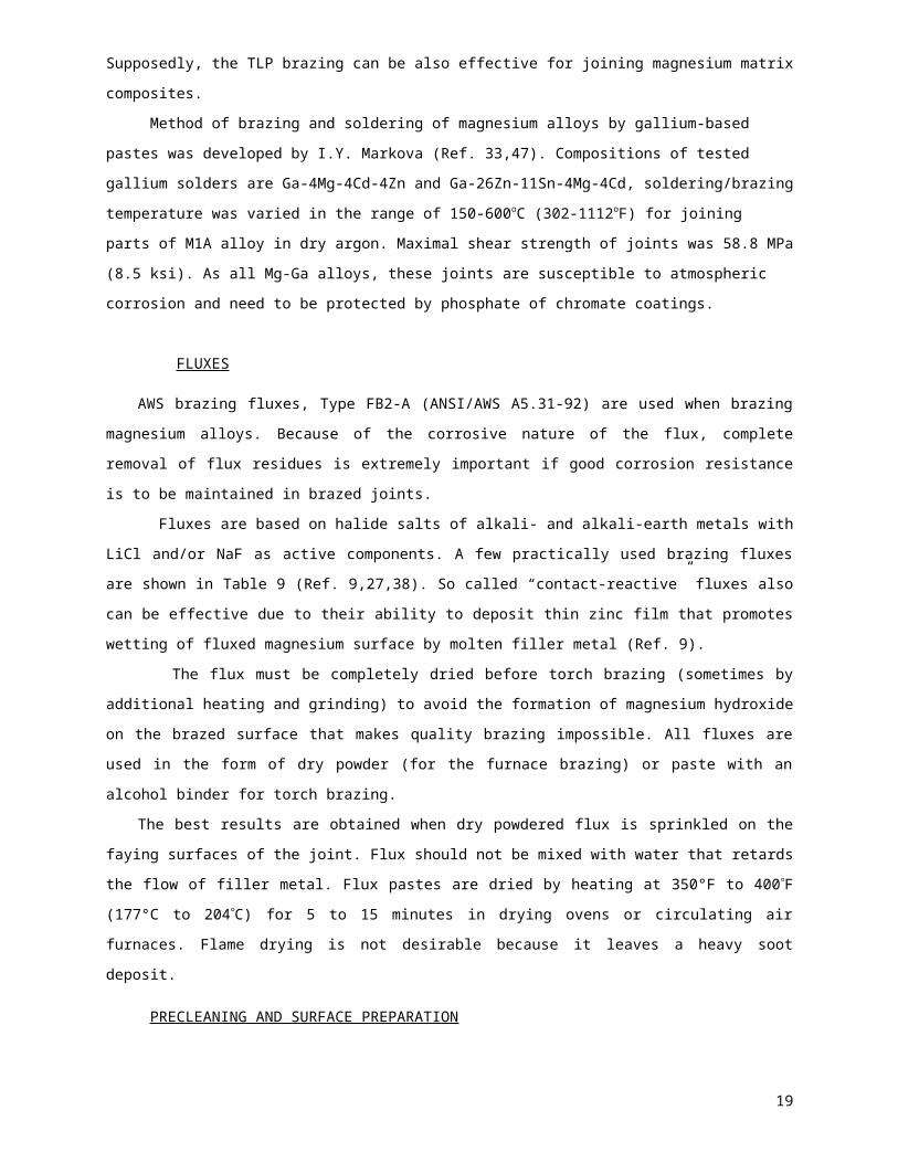
FLUXES
AWS brazing fluxes, Type FB2-A (ANSI/AWS A5.31-92) are used when brazing magnesium alloys.
Because of the corrosive nature of the flux, complete removal of flux residues is extremely important if
good corrosion resistance is to be maintained in brazed joints.
Fluxes are based on halide salts of alkali- and alkali-earth metals with LiCl and/or NaF as active
components. A few practically used brazing fluxes are shown in Table 9 (Ref. 9,27,38). So called
“contact-reactive” fluxes also can be effective due to their ability to deposit thin zinc film that promotes
wetting of fluxed magnesium surface by molten filler metal (Ref. 9).
The flux must be completely dried before torch brazing (sometimes by additional heating and grinding)
to avoid the formation of magnesium hydroxide on the brazed surface that makes quality brazing
impossible. All fluxes are used in the form of dry powder (for the furnace brazing) or paste with an alcohol
binder for torch brazing.
The best results are obtained when dry powdered flux is sprinkled on the faying surfaces of the joint.
Flux should not be mixed with water that retards the flow of filler metal. Flux pastes are dried by heating at
350°F to 400°F (177°C to 204°C) for 5 to 15 minutes in drying ovens or circulating air furnaces. Flame
drying is not desirable because it leaves a heavy soot deposit.
12

PRECLEANING AND SURFACE PREPARATION
Magnesium alloys are usually supplied with preserving oil coating, chromate coated surfaces, or acid
pickled surfaces (Ref. 5). The assemblies to be brazed should be thoroughly clean and free from burrs.
Oil, dirt, and grease should be removed either with hot alkaline cleaning baths or by vapor or solvent
degreasing. Surface films, such as chromate conversion coatings or oxides, must be removed by
mechanical or chemical means immediately prior to brazing.
In mechanical cleaning, abrading with aluminum oxide cloth or steel wool has proved very
satisfactory. Chemical cleaning should consist of a 5-10 min dip in a hot alkaline cleaner followed by a 2
min dip in the ferric nitrate bright pickle solution that is described in Table 10 (Ref. 6, 9). Besides, the
preserving oil coatings can be removed by boiling in 1% aquatic solution of soda for 20-30 min followed
by rinsing with warm water and drying at 140-176oF (60-80oC) (Ref. 27). An interaction between any of
mentioned surface preparation and brazing should be less than 5 h.
T. Watanabe and H. Adachi investigated a positive effect of surface treatment of alloy AZ31B by
pickling in hydrofluoric acid before brazing (Ref. 49). Such pickling produces a thin protective film of MgF 2
on the alloy surface that improves wetting by In-30Mg-4Zn-1Al brazing filler metal at 480-500oC.
Table 10
Chemical treatment solutions
Treatment Composition Method of Application
Ferric nitrate bright pickle
Chromic acid, 1.5 lb (0.68 kg)
Ferric nitrate, 5.33 oz (0.15 kg)
Potassium fluoride, 0.5 oz (0.014 kg)
Water to make one gallon (3.8 L)
Temperature 60–100°F (16–38°C)
0.25 to 3 min immersion followed by cold and hot water rinses and air dry
Chrome pickle
Sodium dichromate, 1.5 lb (0.68 kg)
Conc. nitric acid, 24 fl. oz. (710 mL)
Water to make one gallon (3.8 L)
Temperature 70–90°F (21–32°C)
1 min to 2 min immersion, hold in air 5 s, followed by cold and hot water rinses and air or forced dry 250°F max (121°C max)
Postbraze cleaner (A) Sodium dichromate, 0.5 lb (0.23 kg)
Water to make one gallon (3.8 L)
Temperature 180–212°F (82–100°C)
2 hour immersion in boiling bath followed by cold and hot water rinses and air dry
Postbraze cleaner (B) (1 step) 2-3% solution of Na2CO3
(2 step) Chromium anhydride 150 g/L
Nitric acid 240 g/L
30-60 min immersion in boiling bath followed by cold water rinse. 1-3 min immersion in the bath followed by cold and hot water rinses, and air dry at 140-158oF
13

Temperature 68-86oF (20-30oC) (60-70oC) in drying chamber
POSTBRAZE CLEANING AND CORROSION RESISTANCE
Regardless of the brazing process used, the complete removal of all flux residues is of the utmost
importance. The brazement should be rinsed thoroughly in flowing hot water to remove flux. A stiff-bristled
brush should be used to scrub the surface and speed up the cleaning process (Ref. 6).
The brazement should then be immersed for one to two minutes in chrome pickle, followed by a 1-2
hour boil in one of postbraze flux remover cleaners A or B described in Table 10.
The corrosion resistance of brazed joints depends primarily on the thoroughness of flux removal and
the adequacy of joint design to prevent flux entrapment. Since the brazing filler metal is a magnesium-
based alloy, galvanic corrosion of brazed joints is minimized.
Table 11
Anticorrosive conversion coatings
Treatment Composition Method of Application
Cr-Mn
Alkali NaOH 2 min immersion at
55oC (130oF)
Chemical cleaning CrO3, 0.22-0.44 lb (100-200 g)
Water, 1L
Na2Cr2O7 2H2O, 0.22lb (100 g)
1-15 min immersion in
boiling bath
Conversion
coating
MnSO4 5H2O, 0.11lb (50 g)
MgSO4 7H2O, 0.11lb (50 g)
Water, 1L
5-20 min immersion at
35-55oC (95-130oF)
Cr-Al
Alkali NaOH 2 min immersion at
55oC (130oF)
Chemical cleaning CrO3, 0.22-0.44 lb (100-200 g)
Water, 1L
Na2Cr2O72H2O, 0.22lb (100 g)
1-15 min immersion in
boiling bath
Conversion
coating
NaF, 0.033 lb (15 g)
Na2Cr2O7 2H2O, 0.4 lb (180 g)
Al2SO4 14H2O, 0.022 lb (10 g)
HNO3 70%, 125 mL
Water, 1L
2 min immersion at
35-55oC (95-130oF)
14

If necessary, corrosion resistant of brazed joints or an entire brazed article can be increased with
phosphate coating (Ref. 51) chemically deposited by rubbing the surface or immersing in the water
solution containing NaH2PO4 40-100 g/L, NH4H2PO4 120-180 g/L, (NH4)2SO4 5-20 g/L, and Mg(OH)2 5-15
g/L. The protective coating 2.5-3 m thick is deposited for 1-5 min at 68-95oF (20-35oC).
Corrosion resistance of magnesium alloys and brazed joints can be improved by Cr-Mn or Cr-Al
conversion coatings deposited after chrome pickling by dipping in one of the solutions presented in Table
11 (Ref. 50). Painting with (a) epoxy-based primer, (b) acrylic or polyester color base, and (c) acrylic top
clear paint is principal finishing process having the purposes of better corrosion resistance under the
severe corrosive environment. The completely finished corrosion protection which includes 3-coat and 3-
baking paint films on conversion coated surfaces is so effective that meets automotive industry
regulations to magnesium parts (Ref. 50). Non-chromate conversion coating may be deposited on brazed
magnesium articles from the water solution of 20 g/L cerium chloride (CeCl2) or 10 g/L vanadium oxide
(V2O5) at pH = 6-8 and 40 oC for 5 min (Ref. 52).
Also, sealing treatment at 60oC for 10 sec is recommended after the chemical conversion to provide
excellent corrosion resistance. The sealing agent is selected from vinyl-silane, glycidoxy-silane, and
mercapto-silane, or a titanium coupling agent.
Local protection of brazed joints can be carried out by treating with the solution containing MgO 9 g/L,
CrO3 45 g/L, and H2SO4 1.5 g/L. This solution provides deposition of light-gold colored oxide film. To
prepare this composition, magnesium oxide is mixed with small amount of the acidic water solution up to
a paste state, then CrO3 and remained water are added. Stirring of the resulting mixture continues up to
full dissolution of MgO (Ref. 53).
The surface to be coated is prepared with a sand paper, degreased by acetone or the like, and dried.
The oxidative solution is deposited by fabric or cotton tampon, processing time is 2-3 min. Wet residues
should be removed from the brazed joint.
DESIGN OF BRAZED STRUCTURES
Design of brazed joints of magnesium alloys needs detail consideration in a special article. We have
to make here only two notes about main specifics of magnesium brazing design.
Firstly, magnesium alloys have low yield strength. On the one hand, this means that overlapping value
equal to two thickness of base metal is usually sufficient to provide the shear strength of brazed joints. On
the other hand, it is reasonable to make overlapping as big as possible to increase total thickness, and
consequently, strength of the brazed structure. In each case, the designer has to make appropriate
decision in accordance with operational conditions of the brazed structure.
Secondly, magnesium matrix composites are susceptible to stress concentration due to big difference
between mechanical properties of hard fibers and soft matrix. In order to prevent their failure caused by
stress concentration in overlapping, the design of the brazed joints should provide distribution of stresses
outside the overlapping edges. This can be done by changing the edge shape or local change of cross-
section of the base metal part. Sometimes, so called “false” stress concentrators just in the overlapping
area may be effective for leveling average grade of stresses along the brazed joint.
15

TYPICAL APPLICATIONS OF MAGNESIUM ALLOYS AND THEIR BRAZED JOINTS
The use of magnesium alloys in car design is continuously expanded, and now includes also ultra-
lightweight matrix composites. Typical automotive applications are engine blocks, cylinder liners,
pushrods, valve spring retainers, instrument panels, clutch and brake pedal support brackets, steering
column lock housing, and transmission housings. The design of magnesium instrument panel for the
General Motor vans allowed to save 5.9 kg per piece against aluminum welded tubular design. The
Volkswagen-Kaefer comprises now about 20 kg (44 lbs) of magnesium alloys and composites (Ref. 54).
The target of Automotive industry is to achieve a 45% weight saving in 2009 relatively to the average
car weight in 1990. Obviously, the part of aluminum- and magnesium-based materials must be
substantially increased according to published forecast (Ref. 11,55,56), Table 12. A comparison of
production costs (Table 13) shows that the cost of lightweight advanced materials will go down in the
nearest future though will remain higher than the cost of traditional steel or aluminum.
Material-handling equipment and commercial applications include parts of magnesium dockboards,
grain shovels, and gravity conveyors, luggage, computer housings, digital camera housings, electrical
conductors, and hand-held tools.
Table 12 The change in structure of materials in a typical family sedan in North America (Ref. 11)
MaterialIn year 2000) Predicted (In year 2009)
Mass, kg Portion, % Mass, kg Portion, %
Steel 648 54 92 16
Cast iron 132 11 23 4
Aluminum 96 8 138 24
Magnesium 2.4 0.2 87 15
Plastics 96 8 132 23
Fluids/Lubricants 72 6 35 6
Rubber 48 4 23 4
Glass 36 3 29 5
Others 69.6 5.8 17 3
Total 1200 kg 100% 576 kg 100%
Table 13
Mass saving over steel in the car production and cost of lightening (data on year 2000) (Ref. 11)
Material Steel AluminumAlloy 6061
Aluminum matrix
composite 6061/15SiCp
Magnesium alloy AZ80
Magnesium matrix
composite ZC71/12SiCp
Cost per unit weight * 1 3.4 4.8 7.5 10.6Mass for equal stiffness, kg 1 0.5 0.5 0.4 0.4
16

Cost for equal stiffness * 1 1.7 2.3 2.9 3.9
Mass for equal strength, kg 1 0.3 0.3 0.2 0.2
Cost for equal strength * 1 1.0 1.3 1.6 2.2
Mass saving over steel for equal stiffness, kg
0 0.5 0.5 0.6 0.6
Mass saving over steel for equal strength, kg
0 0.7 0.7 0.8 0.8
Cost for 1kg mass saving for equal stiffness *
1 3.4 4.3 4.8 6.2
Cost for 1kg mass saving for equal strength *
1 1.4 1.8 2.3 2.8
* in relative values of steel price
In the aerospace industry, lightweight and stiff magnesium alloys are employed in various units and
devices, for example, aircraft transmission systems and their auxiliary components, gear housings, rotor
housings, and generator housings in cold areas of engines (Ref. 57). For example, helicopter
transmission housings are manufactured from forged alloys AZ80 and ZK60 (Ref. 55). Graphite fiber-
reinforced magnesium matrix composites offer the best combination of low specific weight (target is 5 kg
per m2 of the base plate), low coefficient of thermal expansion 2 x 10⁻⁶ K-1 , high specific stiffness, and
high thermal conductivity of any known space mirror material. This materials and efficient joining
techniques to produce low cost mirrors are sought for space deployed optical systems. For example, the
Swiss company EMPA reported about the manufacture of parts of Hubble Space Telescope from a
MgAl1/T300 composite reinforced with 60 vol.% of graphite fibers, whereby the Young’s modulus of the
composite is 155 GPa (22.4 Mpsi) at density 1.8 g/cm3 (Ref. 25). Brazing is the valuable technique for
joining of all composite structures. New creep-resistant cast magnesium alloys have a great potential for
aerospace applications, and brazing community shall focus R & D on development of suitable creep-
resistant brazing filler metals to response future needs of the Aerospace industry.
In audio-, video-, computer-, and communication equipment plastics are being replaced by magnesium
alloys that have advantages in strength, heat sink, and service life. Consequently, thin magnesium net
shapes are used now in many models of cellular phones, laptop computers, camcorders, etc. (Ref. 37).
Joining of magnesium matrix composites reinforced with carbon or ceramic fibers and particles is
possible only by brazing. These high-tech materials are widely utilized for automobile parts, for large
spacecraft panels, space based telescopes, space based optical systems, and space stations. The
composite brazed structures will also have application in missiles and in aircraft, both civilian and military.
Fig. 2 shows a dip brazed M1A magnesium alloy microwave antenna (Ref. 6).
17
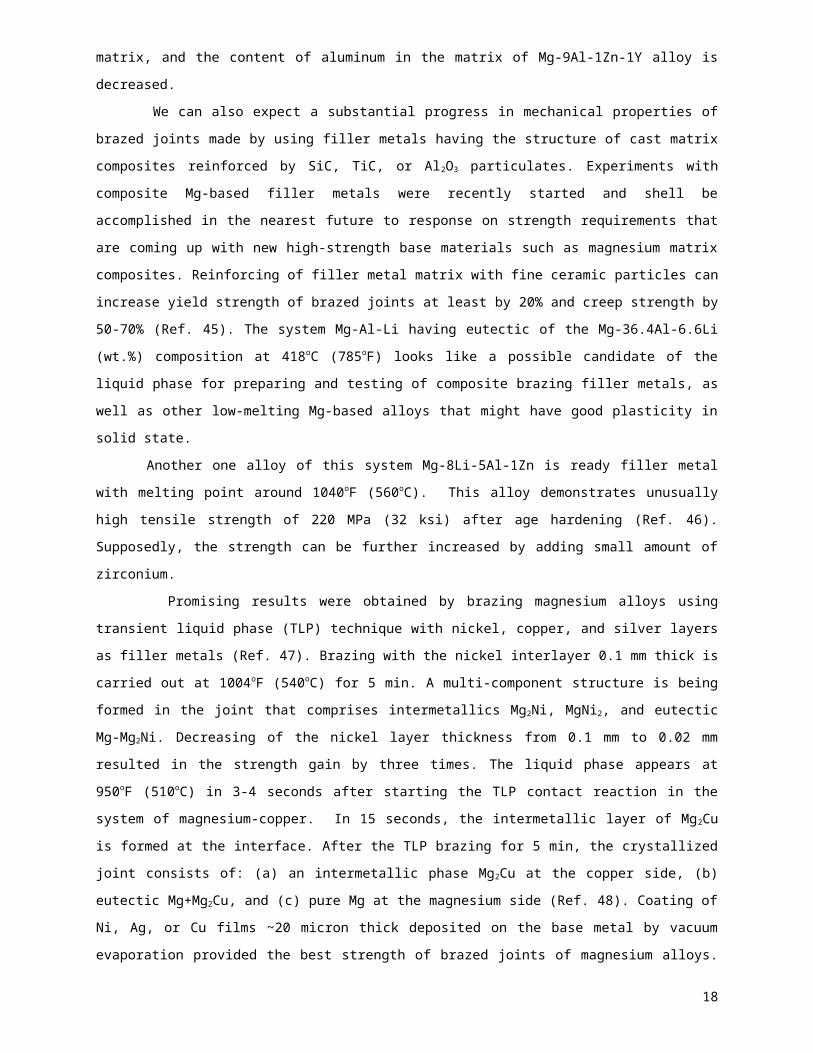
Fig. 1. Structure of brazed joint of AZ91C/15SiCp composite material made by
Mg-12Al-2Ca filler metal
Fig.1 Dip brazed M1A microwave antenna
CONCLUSIONS
1. Conventional standard brazing materials and traditional brazing technologies are suitable for joining
new high-performance cast and extruded magnesium alloys that came up on the market since 1990.
But standard brazing filler metals BMg-1, BMg-2a, and MC3 cannot be recommended for joining
magnesium matrix composites due to negative effect of high brazing temperature on macrostructure
of the composites. New brazing filler metals need to be developed for furnace brazing of magnesium
matrix composites at 842-968oF (450-520oC). These prospective filler metals should provide shear
and tensile strength of brazed joints at least 25 ksi (175 MPa).
2. Brazing filler metals having operational temperatures in the range of 490-520oC (914-968oF) need to
be developed and comprehensively tested for joining wrought, work-hardened and tempered
magnesium alloys. Low-melt brazing filler metals will allow to avoid significant loss of mechanical
properties of base metals caused by brazing with conventional standard filler metals.
3. New filler metals promising to improve mechanical properties of brazed joints both bulk and
composite magnesium alloys, such as alloy systems of Al-Mg-Cu, Mg-Al-Ca, Mg-Li-Al-Zn, and Mg-Al-
Zn-Ca, should be tested widely and introduced in the industry.
4. Filler metals designed for brazing extruded (or rolled) magnesium matrix composites should have as
low as possible brazing temperature due to low recrystallization temperature of the matrix and
anisotropic structure of the composites. Brazing temperature is not so critical for joining cast
magnesium matrix composites.
5. Substantial progress in mechanical properties of brazed joints can be reached with filler metal having
the structure of cast matrix composites reinforced by SiC, TiC, or Al2O3 particulates. Composite filler
metals should have low viscosity in molten state in the range of 842-968oF (450-520oC) to fill capillary
brazing gaps of 0.1-0.25 mm (0.004-0.01 in.).
18
6. It is necessary to check a strengthening effect of thorium, yttrium, and /or zirconium additions in
brazing filler metals, just as this effect was successfully demonstrated in raising tensile strength and
creep resistance of cast magnesium alloys.
7. Melt spinning technology should be developed to manufacture Mg-based brazing filler metals in the
form of thin amorphous foil that is necessary for joining large flat or shaped panels of magnesium
matrix composites, including ultra-strength Th- or Zr-alloyed matrix reinforced by SiC or graphite
fibers.
8. Anti-corrosive chemical treatment including the deposition of phosphate coatings or conversion Cr-
based coatings is recommended to improve corrosion resistance of brazed joints and increase
service life of joined magnesium alloy articles working at environmental impact in automotive and
aerospace applications.
9. Brazing of ceramics (especially silicon carbide and silicon nitride) to magnesium alloys needs to be
investigated and mechanical properties of brazed joint of such dissimilar base materials should be
tested. The successful developments of new reliable, cost-effective brazing technologies will open up
commercial applications in automotive, aircrafts, avionics, and electronic packages, as well as heat-
sinking and lightweight hybrid metal-ceramic structures.
10. Magnesium matrix composites are susceptible to stress concentration. In order to prevent their failure
due stress concentration caused by overlapping, the design of the brazed joints should provide
distribution of stresses outside the overlapping edges.
BIBLIOGRAPHY
1. Duhaime P., Mercille P. and Pineau M. 2002. Electrolytic process technologies for the production
of primary magnesium, 25th Magnesium Commodity Meeting, London.
2. Magnesium and Magnesium Alloys, ASM Specialty Handbook, 1999, Edited by Avedesian M. M.
and Baker H., Materials Park, OH.
3. Dahle A.K., StJohn D.H., and Danlop G.L. 2000. Developments and challenges in utilization of
magnesium alloys, Materials Forum, v.24: 167-182.
4. Magnesium and Magnesium Alloys. 1998. In Metals Handbook, 2nd Edition, ed. by J.R. Davis,
ASM International, Materials Park, OH, pp.559-574.
5. Busk R.S. 1987. Magnesium Products Design, Int. Magnesium Assoc., NY.
6. Lockwood L., Shapiro A.E. 2005. Brazing of magnesium, In Brazing Handbook, 5th Edition, AWS,
Miami.
7. Albright D. 1995. Magnesium diecasting alloys. In Automotive materials at the SAE Show,
Advanced Materials & Processes, No. 5: 26.
8. Song J.W., Kim C.W., Han J.W., Kim M.S., and Hwang S.K. 2003. Improvement in mechanical
properties of magnesium alloy AZ31 fabricated by casting and subsequent plastic working,
Material Science Forum, v.439: 227-232.
19

9. Shein Y.F. 1984. Brazing of magnesium alloys, in Brazing Reference Book, 2nd Edition, Editors
I.E.Petrunin and S.N.Lotsmanov, Moscow, 320 pp.
10. Lusignea R.W. 2003. Thin-walled metal matrix composites for spacecraft applications,
www.spacepda.net/mobile/abstracts.
11. Kevorkijan V., Smolar T., Dragojevich V., and Lenarcic D. 2003. AZ80 and ZC71/SiC12P closed
die forging for automotive applications, Metalurgija - J. of Metallurgy, v. 9, No.1: 23-36.
12. Gui M., Han J., and Li P. 2003. Fabrication and characterization of cast magnesium matrix
composites, J. of Mat. Eng. and Performance, v. 12, No.2: 128-134.
13. Jayalakshmi S., Kalvas S., and Seshan S. 2003. Properties of squeeze cast Mg-10Al-Mn alloy
and its alumina fiber composites, J. of Materials Science, v.38, 1383-1389.
14. Kainer K.U. 1996. Aluminum and magnesium based metal matrix composites, Kovine, zlitine,
tehnologije, v. 30, No.6: 509-516.
15. Muramatsu H., Kondon K., Yuasa E., and Aizawa T. 2003. Mechanical properties of Mg2Si/Mg
composites via powder metallurgy process, JSME Int. J., Ser. A, V. 46, No.3: 247-250.
16. Essa Y.E., Fernandez-Saez J, and Perez-Castellanos J.L. 2003. Experimental study of the strain
rate and temperature effects on mechanical behavior of a magnesium-SiC composite, J. of
Testing and Evaluation, v. 31, No.6: 449-457.
17. Kondoh K. and Luangvaranunt T. 2003. New process to fabricate magnesium composites using
SiO2 glass scraps, Materials Transactions, v. 44, No.12: 2468-2474.
18. Jiang Q.C., Li X.L., and Wang H.Y. 2003. Fabrication of TiC particulate reinforced magnesium
matrix composites, Scripta Materialia, v. 48: 713-717.
19. Schaller R. 2003. Metal matrix composites, a smart choice for high damping materials , J. of
Alloys and Compounds, v. 355: 131-135.
20. Sasaki G. 2003. Material mechanical properties and microstructure of magnesium matrix
composites fabricated by casting process, Materials Science Forum, v. 426-432: 2015-202.
21. Zheng M., Wu K., Liang H., Kamado S., and Kojima Y. 2002. Microstructure and mechanical
properties of aluminum borate whisker-reinforced magnesium matrix composites, Material
Letters, v. 57, 558-564.
22. Dieringa H., Morales E., Fischer P., Kree V., and Kainer K. 2002. Gefuge und Mechanische
Eigenschaften von Magnesium Matrix Verbundverkstoffen, Sonderbaende der Practischen
Metallographie, v. 33: 91-96.
23. Withers J.C., Pickard S.M., Loutfy R.O., Fu R., Avery G. and Fritz S. 2000. Squeeze cast
magnesium matrix composites, Processing and Fabrication of Advanced Materials VIII, 827-837.
24. Zheng M.Y., Wu K., Liang M., Kamado S., Kojima Y. 2004. The effect of thermal exposure on the
interface and mechanical properties of Al18B4O33/AZ91 magnesium matrix composite, Material
Science and Eng., v. A 372: 66-74.
25. Beffort O. 2001. Metal matrix composites from Space to Earth, Materials Day, ETH-Zurich.
26. Kudela S. 2003. Magnesium-Lithium matrix composites – an overview, Int. J. of Materials &
Product Technology, v. 18, No. 1-3: 91-115.
27. Shapiro A.E. 1982. Filler metals, fluxes, and gaseous atmospheres for brazing and soldering,
TsNITI, Moscow, 167 pp.
20

28. Sakkinen D. 1995. Magnesium alloy metallurgy. In Automotive materials at the SAE Show,
Advanced Materials & Processes, No. 5: 26-27.
29. Foerster G. 1998. HiLon: A new approach to magnesium die casting, Advanced Materials &
Processes, No.10: 79-81.
30. Tsukeda T., Uchida R., Suzuki M., Koike J, and Maruyama K. 2003. Newly developed heat-
resistant magnesium alloy for thixomolding, Materials Science Forum, v. 419-422: 439-444.
31. Bakke P., Pettersen K. and Aibright D. 2004. The influence of Sb, Si, and Sn on mechanical
properties of Mg-Al alloys, Magnesium Technology 2004, ed. By A.A. Luo, TMS: 289-296.
32. Chang C.F., Das S.K., and Zedalis M.S. 1994. Rapidly-solidified Al-Mg alloys for braze foils,
U.S.Patent 5332455.
33. Lashko S.V. and Lashko N.F. 1988. Brazing of Metals, Mashinostrienie, Moscow, 376 p.p.
34. Masuda N., Ishikawa T., Miyadzawa Y., Ariga T, and Matsumami H. 2001. Brazing of magnesium
alloys, DVS-Berichte, v.212: 353-355.
35. Bronfin B., Aghlon E., von Buch F., Schumann S., and Katzir M. 2003. High-strength and creep-
resistant magnesium alloys, EP 1308531.
36. Shapiro A.E. 2003. Brazing filler metals of Mg-Al-Ca system, U.S. Patent Application.
37. Decker R.F. 1998. The renaissance in Magnesium, Advanced Materials & Processes, No. 2: 31-
33.
38. Watanabe T., Komatu S., Yanagisawa A., and Konuma S. 2004. Development of flux and filler
metal for brazing magnesium alloy AZ31B, Yosetsu Gakkai Ronbunshu, v. 22, No.1: 163-167.
39. Watanabe T., Komatsu S. and Oohara K. 2005. Development of Flux and Filler Metal for Brazing
Magnesium Alloy AZ31B, Welding Journal, v. 84, No. 3: 37s-40s.
40. Watanabe T. 2004. Fluxes and brazes for brazing magnesium alloys, Japanese Pat.
2004050278.
41. Wielage B. and Muecklich S. 2003. Flux-free soldering of magnesium materials, Welding and
Cutting, v. 55, No.4: 191-192.
42. Muecklich S., Klose H., and Wielage B. 2003. Ultrasonic assisted brazing of magnesium, Proc. of
2nd Int. Brazing/Soldering Conf., San Diego.
43. Evans D.B. and Claridge R.C. 1994. Near-ambient pressure braze consolidation process for fiber-
reinforced magnesium matrix composites, U.S. Patent 5353981.
44. Zhang S.C., Wei B.K., Lin H.T. 2003. Effect of yttrium on as-cast structure and age hardening of
Mg-9Al-1Zn alloy, Cailiao Rechuli Xuebao (China), v. 24, No.3: 23-26.
45. Shapiro A.E. 2004, Low-melting composite brazing filler metals for joining magnesium matrix
composites, US Patent Application.
46. Schemme K. 1993. Development of super-light magnesium materials, VDI-Forschritt-Berichte,
No. 293.
47. Markova I.Y., Petrunin I.E, and Grzhimalsky L.L. 1974. Investigation of a method of brazing
magnesium alloys, Welding Production, No.3:57-61.
48. Petrunin I.E., Markova I.Y. and Ekatova A.S. 1976. Metallurgy of brazing, “Metallurgia”, Moscow,
264 p.p.
21

49. Watanabe T. and Adashi H. 2004. Effect of halogen surface treatment on the ultrasonic
weldability and brazeability of magnesium alloys, J. of Japan Institute of Light Metals, vol. 54, No.
5: 182-186.
50. Sim Y. and Kim J. 2003. Surface treatment of automotive cast parts of magnesium alloys,
Corrosion Science and Technology, v. 2, No.2: 102-108.
51. Zhirnov A.D., et al. 2003. Method for manufacturing protective coating on magnesium alloys,
Russian Pat. 2207400.
52. Ger M.D., Yang K.H., Sung Y., Hwu W.H., and Liu Y.C. 2004. Method for treating magnesium
alloys by chemical conversion, U.S. Patent 6,755,918.
53. Griliches S.Y. 1978. Oxide and phosphate coatings on metals, Mashinostroenie, Leningrad, p. 47.
54. Beffort O. and Rohr L. 2000. Magnesium Verbundverkstoffe – neue Leichtbaukonzepte fur das
angehende Jahrhundert, Nachhaltige Material- und Systemtechnik, Ed. W. Muster and K.
Schlaepfer, 21-28.
55. Agnew S.R. 2004. Wrought magnesium: A 21st century outlook, JOM, May: 20-21.
56. Luo A.A. 2002. Magnesium: Current and potential automotive applications, JOM, February: 42-
48.
57. Zuemer N. 1998. Magnesium alloys in new aeronautic equipment, Proc. of the Conf. on
Magnesium Alloys and their Applications, Wolfsburg, Germany, 125-132.
58. Kezik V.Y. and Kalinichenko A.S. 2004, Some data about structure and properties of
macrocomposites based on lightweight metals, Metallurgia, v. 28, 120-131.
22

Table 5Composition and Physical Properties of Commercial Brazing Filler Metal
Designation
Nominal composition, wt.%
(Balance Mg) Specific Gravity Temperatures
AWS A5.8 ASTM
or UNS Al Zn Mn Cu Be Ni Others g/cm3 lbs/in3
Solidus
°F oC
Liquidus
°F oC
Brazing Range
°F oC
BMg-1 AZ92A 8.3-9.7 1.7-2.3 0.15-0.5 0.05 0.0002-0.0008 0.005 0.3 1.83 0.066 830 443 1110 599 1080-1140 582-616
BMg-2a AZ125A 11-13 4.5-5.5 - - 0.008 - 0.3 2.10 0.076 770 410 1049 565 1058-1103 570-595
MC3* UNS
M11920
8.3-9.7 1.6-2.4 0-0.1 0-0.25 0.0005 0-0.01 <0.3Si 1.83 0.066 830 443 1110 599 1120-1140 605-615
*Standard Japanese filler metal
23

Table 6Compositions and Physical Properties of Low Temperature Brazing Filler Metals
Designation
Nominal composition, wt.%
(Balance Mg) Specific Gravity Temperatures
Al Zn Mn Be Others g/cm3 lbs/in3
Solidus
°F oC
Liquidus
°F oC
Brazing Range
°F oC
GA432
P430Mg
P380Mg
P435Mg
P398Mg*
2 55 - - -
0.7-1.0 13-15 0.1-0.5 - 0.3
2.0-2.5 23-25 0.1-0.5 - 0.3
25-27 1-1.5 0.1-0.3 - -
21-22 0.2-0.5 0.1-0.3 - Cd 25-26
4.7 0.169
2.7 0.097
3.0 0.107
2.1 0.076
3.7 0.133
626 330
716 380
644 340
815 435
750 398
680 360
806 430
716 380
968 520
779 415
925-940 495-505
1020-1040 550-560
896-932 480-500
968-1040 520-560
806-932 430-500
* Filler metal P398Mg is used for correction defects of magnesium cast
24

Table 9
Compositions and Operational Temperatures of Magnesium Brazing Fluxes
Flux Flux Composition, wt.% Temperatures
KCl LiCl NaCl NaF LiF CaCl2
CdCl2 ZnF2 ZnCl2 CryoliteCarnalite ZnO Melting
°F °C
Brazing Activity°F °C
F380Mg Bal. 37 10 10 - - - - - 0.5 - - 716 380 716-1110 380-600
F530Mg Bal. 23 21 3.5 10 - - - - - - - 986 530 1000-1110 540-600
F540Mg Bal. 23 26 6 - - - - - - - - 1000 540 1004-1202 540-650
F390Mg Bal. 30 - - - - 15 10 10 - - - 734 390 788-1112 420-600
F535Mg Bal. - 12 4 - 30 - - - - - - 995 535 1004-1202 540-650
F400Mg - - - - - - - - - 8 89 3 752 400 797-1148 415-620
F450Mg - 9 15 - - Bal. - - - - - - 842 450 842-1202 450-650
25

Table 1
Compositions and physical properties of brazeable magnesium alloysASTM Alloy Designation
Available Forms
Nominal Composition, %
(Balance Mg)
Density Temperatures
Al Mn Zn Zr Si Cu Others g/cm3 lbs/in3Solidus Liquidus Brazing Range
(recommended)°C oF °C oF °C oF
M1A E, S - 1.5 - - - - - 1.77 0.064 648 1198 650 1202 580-620 1076-1148
AZ31B E, S 3.0 0.5 1.0 - ≤0.3 ≤0.1 Ni ≤0.3 1.78 0.064 566 1050 632 1070 500-560 932-1040
AZ61A E 6.5 0.3 1.0 - ≤0.1 - - 1.80 0.065 525 977 610 1130 495-505 925-940
AZ63A C 6.0 0.25 3.0 - ≤0.3 ≤0.25 - 1.82 0.066 455 860 610 1130 430-450 806-842
AZ91C C 8.7 0.2 0.7 - ≤0.3 ≤0.1 Ni ≤0.3 1.81 0.065 468 875 598 1108 430-460 806-860
AS41A C 4.3 0.4 0.12 - 1.0 0.06 - 1.78 0.064 570 1058 620 1148 500-560 932-1040
AM100 C 10.0 0.2 ≤0.3 - ≤0.3 ≤0.1 - 1.81 0.065 465 870 595 1102 430-460 806-860
ZE10A S - - 1.2 - - - REM 0.17 1.76 0.063 593 1100 646 1195 560-590 1040-1094
ZK21A E - - 2.3 0.6 - - - 1.79 0.064 626 1159 642 1187 580-620 1076-1148
ZK51A C - - 4.6 0.7 - ≤0.1 - 1.83 0.066 550 1022 640 1185 500-540 932-1004
ZK60A E, S - - 5.5 0.4 - - - 2.06 0.074 520 970 635 1175 495-505 925-940
QE22A C - - 0.7 - - Ag 2.5,REM 2.0
1.83 0.066 535 995 640 1185 490-520 914-968
QH21A C - - 0.7 - - Ag 2.5REM 2.0,
Th 1.0
1.84 0.067 535 995 640 1185 490-520 914-968
HK31A C - - 0.3 0.7 - - Th 3.3 1.85 0.067 642 1187 648 1200 580-620 1076-1148
ZC71 E, S - 0.5 6.5 - - 1.25 - 2.15 0.080 420 788 630 1166 390-410 734-770
26

* E = Extruded shapes and structural sections. S = Sheets and plates. C = Castings.
** Coefficient of thermal expansion of all magnesium alloys is in the range of (25-27) x 10-6 m/m∙oC [(14-15) ) x 10-6 in/in
27

28