Magne Blast
47
NRC Medium Voltage Circuit Breaker Training CHAPTER 6 INTRODUCTION TO GE MAGNE-BLAST CIRCUIT BREAKERS
-
Upload
shahrizal-erlangga -
Category
Documents
-
view
93 -
download
7
description
magne blast
Transcript of Magne Blast
NRC Medium Voltage Circuit Breaker Training
CHAPTER 6
INTRODUCTION TO GE MAGNE-BLAST CIRCUIT
BREAKERS
Learning Objectives
• The basic function of the Magne-Blast circuit breaker.• How the Magne-Blast breakers are classed or grouped.• How the breaker frame size method further identifies the breaker.• The component attributes of the Magne-Blast breaker:
• Mounting Arrangementg g• Primary Contacts and Arc Chutes• Electrical Devices including wiring• Mechanical and Safety Interlocks• Operating Mechanism
• Basic understanding of common failure modes of Magne-Blast Breakers.• Basic understanding of maintenance scheduling.• Basic understanding of subcomponent replacement.• Basic understanding of design upgrades for the Magne-Blast breakers.• Proper lubrication type for Magne-Blast breakers.• Basic understanding of routine maintenance using the Preventative
Maintenance Manual for the Magne-Blast Circuit Breaker.
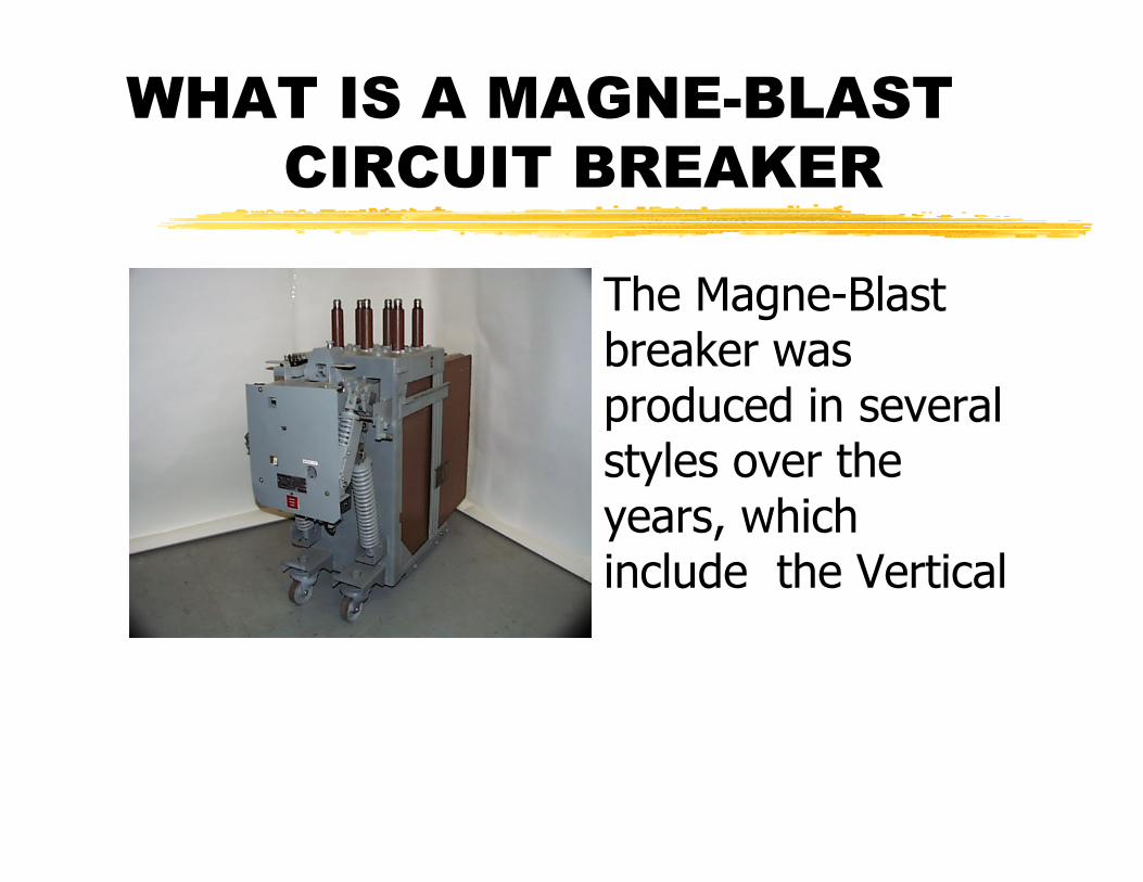
WHAT IS A MAGNE-BLAST CIRCUIT BREAKER
• The Magne-Blast breaker was produced in several styles over the years, which include the Vertical

WHAT IS A MAGNE-BLAST CIRCUIT BREAKER
and the Horizontal “Draw out “designs.

WHAT IS A MAGNE-BLAST CIRCUIT BREAKER
• Early in production, the Magne Blast breaker was an “ACB” (Air Circuit breaker) with a Solenoid operated mechanism.

HOW MAGNE-BLAST CIRCUIT BREAKERS ARE CLASSED
• Voltage Class MEDIUM. Interrupting Capacity
• Also grouped Maximum Interrupting
capacity or MVA.

MAJOR COMPONENT ATTRIBUTES FOR THE MAGNE-BLAST BREAKER
• The chassis contains the primary contact assembly and bushings, interlocks and ground strapinterlocks and ground strap.
MAJOR COMPONENT ATTRIBUTES FOR THE MAGNE-BLAST BREAKER
• As the operating mechanism design changed GE changed the operating mechanism designation to differentiate between the mechanisms.

MAJOR COMPONENT ATTRIBUTES FOR THE MAGNE-BLAST BREAKER
• The primary contact assembly is the main current carrying part of the breaker. The assembly consists of all the barriers, arc chutes and puffer system.
Stationary Arcing Contacts
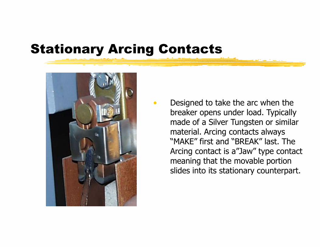
• Designed to take the arc when the breaker opens under load. Typically made of a Silver Tungsten or similarmade of a Silver Tungsten or similar material. Arcing contacts always “MAKE” first and “BREAK” last. The Arcing contact is a”Jaw” type contact meaning that the movable portion slides into its stationary counterpart.

PRIMARY CONTACT ASSEMBLY FOR THE MAGNE-BLAST BREAKER
Stationary Main Contacts
Designed to carry the Primary load current. Usually made of Silver Cadmium Oxideof Silver Cadmium Oxide. Main contacts “MAKE” last and “BREAK” first. The Main contacts are a “BUTT” type contact meaning that the main contacts make flat against each other when the breaker is CLOSED.

PRIMARY CONTACT ASSEMBLY FOR THE MAGNE-BLAST BREAKER
Moving Contact Assembly
Consisting of Main contacts, Arcing contactsArcing contacts, Operating Rod and the Puffer Tube. The Moving Contact Assembly connects the “LINE” and “LOAD” bushings when the breaker is “CLOSED”.
PRIMARY CONTACTS FOR THE MAGNE-BLAST BREAKER
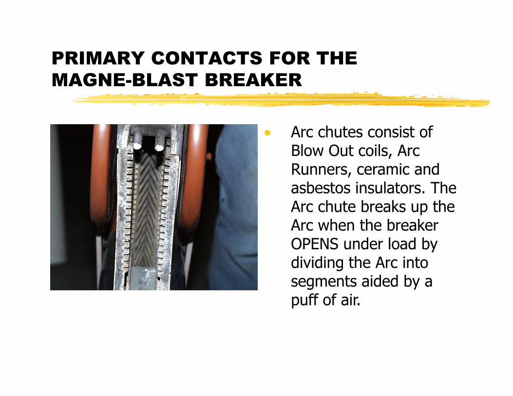
• Arc chutes consist of Blow Out coils, Arc Runners, ceramic and asbestos insulators. The Arc chute breaks up the Arc when the breaker OPENS under load by dividing the Arc into segments aided by a puff of air.
PRIMARY CONTACTS FOR THE MAGNE-BLAST BREAKER
• Insulating barriers and cover- The Barriers isolate all the conductive parts of the breaker from each other and the breaker frame.

COMMON ELECTRICAL DEVICES FOR THE MAGNE-BLAST BREAKER
• Release Latch Monitoring Switch
This switch if OPEN will notThis switch if OPEN will not allow the breaker to CHARGE electrically. Ensures Close Latch is in the RESET position when CLOSED.

COMMON ELECTRICAL DEVICES FOR THE MAGNE-BLAST BREAKER
• Interlock Switches
Provides remote indication that the breaker isthat the breaker is RACKED IN. This switch if OPEN will not allow the breaker to CHARGE or CLOSE electrically.

COMMON ELECTRICAL DEVICES FOR THE MAGNE-BLAST BREAKER
Auxiliary Switch
Provides remote indication of breaker status and a path to the Shunt Trip Coil, allowing the breaker to OPEN electrically. Can have up to 5 N/O and 5 N/C contacts in a single housing. The switch consists of both “A” and “B” contacts. “A” contacts are OPEN when breaker is OPEN and CLOSED when the breaker is CLOSED. “B” contacts do the opposite of “A” contacts.

COMMON ELECTRICAL DEVICES FOR THE MAGNE-BLAST BREAKER
Close Coil and Trip Coil
The close coil closes the breaker The Trip coilbreaker. The Trip coil opens the breaker. The Close and Trip coils are usually the same physically but may be different electrically.

COMMON ELECTRICAL DEVICES FOR THE MAGNE-BLAST BREAKER
Close Coil and Trip Coil
The Trip coil opens the breaker The Close andbreaker. The Close and Trip coils are usually the same physically but may be different electrically.
COMMON ELECTRICAL DEVICES FOR THE MAGNE-BLAST BREAKER
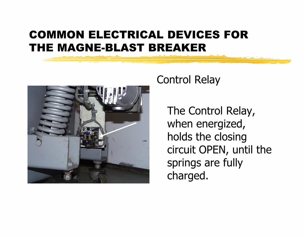
Control Relay
The Control Relay, when energized, holds the closing circuit OPEN, until the springs are fully charged.

COMMON ELECTRICAL DEVICES FOR THE MAGNE-BLAST BREAKER
• Charging Motor
The Charging motor charges the closing
i ( ) M t dspring(s). Mounted below the operating mechanism on the front left side it is connected to a drive fitting and levers to the ratchet wheel.

COMMON ELECTRICAL DEVICES FOR THE MAGNE-BLAST BREAKER
• Secondary Disconnect
Provides the electrical interface between the cubicle and the breaker when the breaker is RACKED IN or OUT and all remote indications of breaker status.
MECHANICAL AND SAFETY INTERLOCKS FOR THE MAGNE BLAST CIRCUIT
BREAKER
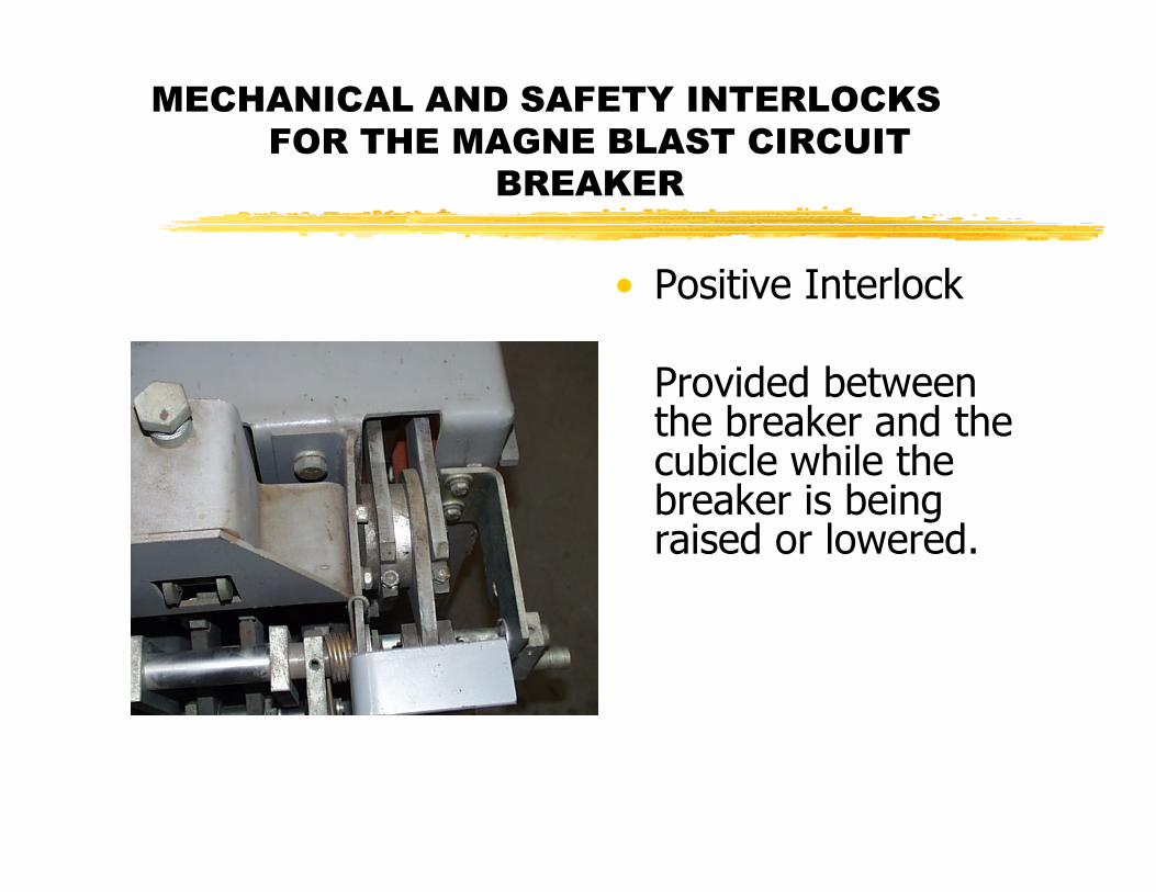
• Positive Interlock
Provided between the breaker and the
bi l hil hcubicle while the breaker is being raised or lowered.

MECHANICAL AND SAFETY INTERLOCKS FOR THE MAGNE BLAST CIRCUIT
BREAKER
• Spring Discharge Interlock
Discharges the Cl i i ifClosing springs if they are charged when the breaker is rolled IN or OUT of the cubicle. .

Operating Mechanism for the Magne-Blast Breaker
• There are several different styles of Operating Mechanisms for the Magne-Blast breakers. The Solenoidbreakers. The Solenoid mechanism was offered in several models from MS-9, MS-10 and MS-13. The “S” designates a solenoid operated mechanism.

Operating Mechanism for the Magne-Blast Breaker
• The newer designs ML-11, ML-12 and ML- 13 are designated “L” for stored energy. The Operating Mechanism is the work horse of the Magne-Blast breaker The mechanismbreaker. The mechanism contains all the mechanical latches, toggle assemblies, cams, rollers, levers and linkages required to OPEN and CLOSE the breaker.
COMMON FAILURE MODES FOR THE MAGNE-BLAST BREAKER
• Historically, there have been many issues with the Magne-Blast breaker in the Nuclear industry over the years. The Magne-Blast breaker is one of the most common breakers in Power Generation Stations throughout the country, regardless of fuel type. The Magne-Blast breaker is also a favorite for large Commercial consumers. There have been several NRC bulletins and Information Notices issued for this breaker model since the mid 1980’s.
COMMON FAILURE MODES FOR THE MAGNE-BLAST BREAKER
• IN # 84-29- Issued by the NRC to address the issue of the Teflon coated fiberglass bushings that were originally installed on the Magne-Blast breaker Operating Mechanism. The Teflon coated bushings would wear out quickly causing key adjustments to be out of specification.

COMMON FAILURE MODES FOR THE MAGNE-BLAST BREAKER
• IN # 90-41- Issued by the NRC to address a broken Prop return spring in the Operating Mechanism and a “Failure to Open” due to a Snap ring retainer coming off the pivot pin. The broken Prop return spring was examined and was found to have cracks at the “Hook” part of the spring.

COMMON FAILURE MODES FOR THE MAGNE-BLAST BREAKER
• IN # 94-54- Issued by the NRC to address the issue of a breaker “Failure to Close” during receipt inspection at the licensee facility from the OEM repair shop. The root cause of the failure was similar to the problem addressed by IN # 96-43. The addition of a second Prop spring resolved this problem.

COMMON FAILURE MODES FOR THE MAGNE-BLAST BREAKER
• Part 21 1995-01-9- Issued to address the broken Trip Crank arm. The breaker failed to OPEN when a Trip signal was sent to the breaker. Since the breaker did not OPEN the Trip coil remained energized until the coil itself burned up.
COMMON FAILURE MODES FOR THE MAGNE-BLAST BREAKER
• IN # 96-43- Issued by the NRC to address the hardened grease in the Operating Mechanism roller bearings. The notice also included a “Failure to Close” due to a weakened prop return spring.

COMMON FAILURE MODES FOR THE MAGNE-BLAST BREAKER
• Part 21 1996-57-0- Issued to address cracks and flat spots on the Prop Latch. Upon receipt inspection the licensee found that the Prop Latch on two breakers was found to be cracked or chipped where the Prop Pin sits when the breaker is latched closed.
COMMON FAILURE MODES FOR THE MAGNE-BLAST BREAKER
• Part 21 1996-77-0- Issued to address the bent Manual Trip handles for a Horizontal Magne-Blast breaker. While in service the breaker “Failed to Close” when thebreaker Failed to Close when the breaker was sent a close signal. Investigation revealed that the Trip paddle was bent in such a way that there was no gap between the Trip paddle and the Trip Latch.

COMMON FAILURE MODES FOR THE MAGNE-BLAST BREAKER
• Part 21 1999-24-3- Issued to address the “Failure to Close” due to the Tripper bar cotter key hitting a Latch Check switch mounting bracket. Due to the close proximity of the Tripper Bar cotter key and the Latch Check Switch, it is essential that the cotter key be properly installed.
COMMON FAILURE MODES FOR THE MAGNE-BLAST BREAKER
• Part 21 2000-04-0- Issued due to the failure of a Normally Closed switch used in the breaker Charging circuit, preventing the breaker from closing on demand. After this notice some plants reconfigured the charge circuit and eliminated the Normally Closed switch from the breaker.

COMMON FAILURE MODES FOR THE MAGNE-BLAST BREAKER
• One of the most common failures for the Magne-Blast breakers are the control switches (Latch check, power bank switches, auxiliary switches, etc.). When using a Digital Multimeter, most all the switches on the Magne-Blast will read a high resistance (>1 Ohm).
COMMON FAILURE MODES FOR THE MAGNE-BLAST BREAKER
• The Primary Bushings and the Arc Chutes are problem areas. Due to there construction, they tend to absorb moisture especially in harsh environments.

MAINTENANCE SCHEDULING FOR THE MAGNE-BLAST BREAKER
• Regular Maintenance is the key to reliability for the 5KV and 15KV Magne-Blast Circuit breakers and all other breaker types. All Nuclear Power plants have an Approved Maintenance Procedure for their circuit breakers These procedures are usually based on thebreakers. These procedures are usually based on the OEM Technical Manual for a specific breaker type. A good PM procedure will change to include additional steps as the plant personnel find problems while performing the PM. It would also include updated SAL’s or equipment upgrades. In most cases the OEM will recommend how often the PM cycle should be.

SUBCOMPONENT REPLACEMENT FOR THE MAGNE-BLAST BREAKER
• During the PM cycle it is possible that some parts on the breaker will be found to be broken, bent, burnt, cracked or worn out. Replacement parts for most Magne Blast breakers are readilyparts for most Magne-Blast breakers are readily available and are well supported by the OEM. Since there are so many variations to accessories for this breaker type it is important to reference the nameplate data and Operating Mechanism type to get the correct parts.

DESIGN UPGRADES FOR THE MAGNE-BLAST BREAKER
• Since the Magne-Blast Breaker was first produced there have been some major changes in the design and upgrades for key parts of the breaker.

DESIGN UPGRADES FOR THE MAGNE-BLAST BREAKER
• In the Operating Mechanism the Teflon coated bushings were replaced with an Aluminum Bronze type bushings. The Teflon bushings were found in the Prop Latch, Toggle linkage, Charging Assembly, Driving and Holding pawls and breaker mechanism frame.

DESIGN UPGRADES FOR THE MAGNE-BLAST BREAKER
• In the Operating Mechanism there is a set screw modification for the Ratchet wheel, Closing Cam, Timing Cam, Close Latch and Trip Latch. The newer design Set screws are self locking and will not slip out after repeated operations.

DESIGN UPGRADES FOR THE MAGNE-BLAST BREAKER
• The Close Latch Return Spring was changed from an extension spring to a torsion spring.
DESIGN UPGRADES FOR THE MAGNE-BLAST BREAKER
• The Holding Pawls Pivot pin was redesigned from a pin with cotter keys on either end to shouldered pin retained by a bolt and flat washer.

DESIGN UPGRADES FOR THE MAGNE-BLAST BREAKER
• The Charge lever was redesigned when the Driving Pawl pivot pin was changed from a two cotter key arrangement to a shouldered pivot pin.

DESIGN UPGRADES FOR THE MAGNE-BLAST BREAKER
• The Primary contacts can now be
t fitt d ithretrofitted with Vacuum type contacts. Only minor modifications to the Operating Mechanism is needed.