Magic Cube -Three-Dimensional Vibration Absorber for ...
9
Purdue University Purdue e-Pubs International Compressor Engineering Conference School of Mechanical Engineering 2008 Magic Cube -ree-Dimensional Vibration Absorber for Pipeline Vibrations Johann Lenz Koeer Consulting Engineers KG Follow this and additional works at: hps://docs.lib.purdue.edu/icec is document has been made available through Purdue e-Pubs, a service of the Purdue University Libraries. Please contact [email protected] for additional information. Complete proceedings may be acquired in print and on CD-ROM directly from the Ray W. Herrick Laboratories at hps://engineering.purdue.edu/ Herrick/Events/orderlit.html Lenz, Johann, "Magic Cube -ree-Dimensional Vibration Absorber for Pipeline Vibrations" (2008). International Compressor Engineering Conference. Paper 1901. hps://docs.lib.purdue.edu/icec/1901
Transcript of Magic Cube -Three-Dimensional Vibration Absorber for ...

Purdue UniversityPurdue e-Pubs
International Compressor Engineering Conference School of Mechanical Engineering
2008
Magic Cube -Three-Dimensional VibrationAbsorber for Pipeline VibrationsJohann LenzKoetter Consulting Engineers KG
Follow this and additional works at: https://docs.lib.purdue.edu/icec
This document has been made available through Purdue e-Pubs, a service of the Purdue University Libraries. Please contact [email protected] foradditional information.Complete proceedings may be acquired in print and on CD-ROM directly from the Ray W. Herrick Laboratories at https://engineering.purdue.edu/Herrick/Events/orderlit.html
Lenz, Johann, "Magic Cube -Three-Dimensional Vibration Absorber for Pipeline Vibrations" (2008). International CompressorEngineering Conference. Paper 1901.https://docs.lib.purdue.edu/icec/1901

1337, Page 1
International Compressor Engineering Conference at Purdue, July 14-17, 2008
- Magic Cube - Three-Dimensional Vibration Absorber For Pipeline Vibrations
Dr.-Ing. Johann Lenz
KÖTTER Consulting Engineers KG
Bonifatiusstraße 400 48432 Rheine
Germany phone +49 (0)5971 - 9710.47
fax +49 (0)5971 - 9710.50 [email protected]
1. INTRODUCTION
Various methods can be implemented to reduce high pipeline vibrations in plants. The basic vibration reduction measures available - when the cause of the vibration cannot be reduced further – are isolation, dampening or absorption of the vibration. The design and use of a newly developed, dampened, three-dimensional vibration absorption system (Magic Cube) for pipeline vibrations will be illustrated in the following based on an example case study. Based on the measurement of the actual high vibrations at the pipes in a natural gas compressor plant, the realization and implementation of the absorber system will be described after explaining the theoretical background.
2. DESCRIPTION OF THE SITUATION In a cavern storage system natural gas is fed into underground storage using reciprocating compressors at pressures of up to 160 bar to cover consumption peaks. The examined reciprocating compressor is equipped with 4 cylinders in Boxer design and is operated at speeds varying between 270 and 350 rpm in 2 pressure stages. High pipeline vibrations were observed at the pipeline between the upstream and the actual pulsation vessel on the suction side (Figure 1).
second pulsation vessel
(suction side)
first pulsation vessel (suction side)
x
y
cylinder discharge side
x
y
Figure 1: Pipeline between the first stage pulsation vessel on the suction side.
1337, Page 2
International Compressor Engineering Conference at Purdue, July 14-17, 2008
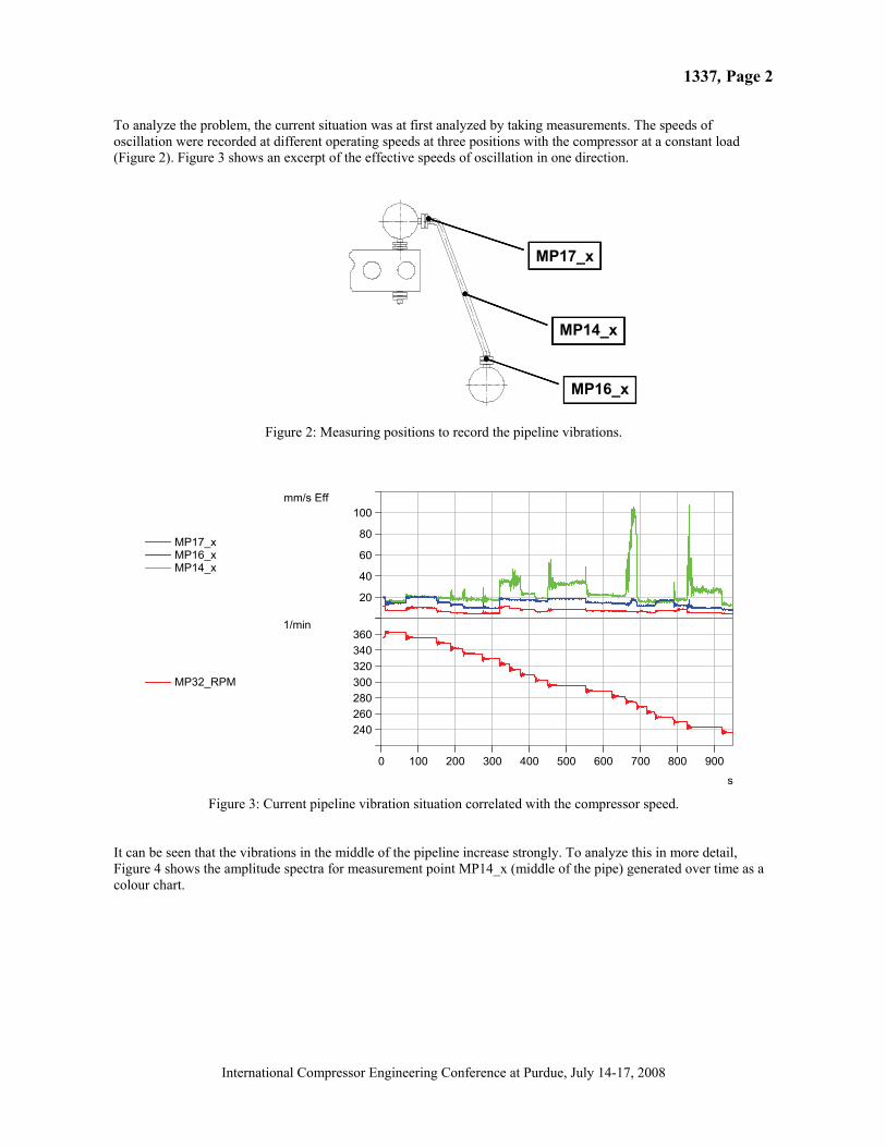
To analyze the problem, the current situation was at first analyzed by taking measurements. The speeds of oscillation were recorded at different operating speeds at three positions with the compressor at a constant load (Figure 2). Figure 3 shows an excerpt of the effective speeds of oscillation in one direction.
MP16_x
MP14_x
MP17_x
Figure 2: Measuring positions to record the pipeline vibrations.
MP17_xMP16_xMP14_x
20
40
60
80
100mm/s Eff
MP32_RPM
240260280300320340360
1/min
0 100 200 300 400 500 600 700 800 900
s Figure 3: Current pipeline vibration situation correlated with the compressor speed.
It can be seen that the vibrations in the middle of the pipeline increase strongly. To analyze this in more detail, Figure 4 shows the amplitude spectra for measurement point MP14_x (middle of the pipe) generated over time as a colour chart.
1337, Page 3
International Compressor Engineering Conference at Purdue, July 14-17, 2008
-60
-50
-40
-30
-20
-10
0
10
20
30
40
50
60mm/s
20 25 30 35 40 45
s
-60
-50
-40
-30
-20
-10
0
10
20
30
40
50
60mm/s
20 25 30 35 40 45
s
0
1
2
3
4mm/s
x = 72.9 Hz
0 20 40 60 80 100 120 140 160 180 200
Hz
0
1
2
3
4mm/s
x = 72.9 Hz
0 20 40 60 80 100 120 140 160 180 200
Hz
0
100
200
300
400
500
600
700
800
900
s
20 40 60 80 100
Hz
0
20
40
60
80
100
120
140
160mm/s
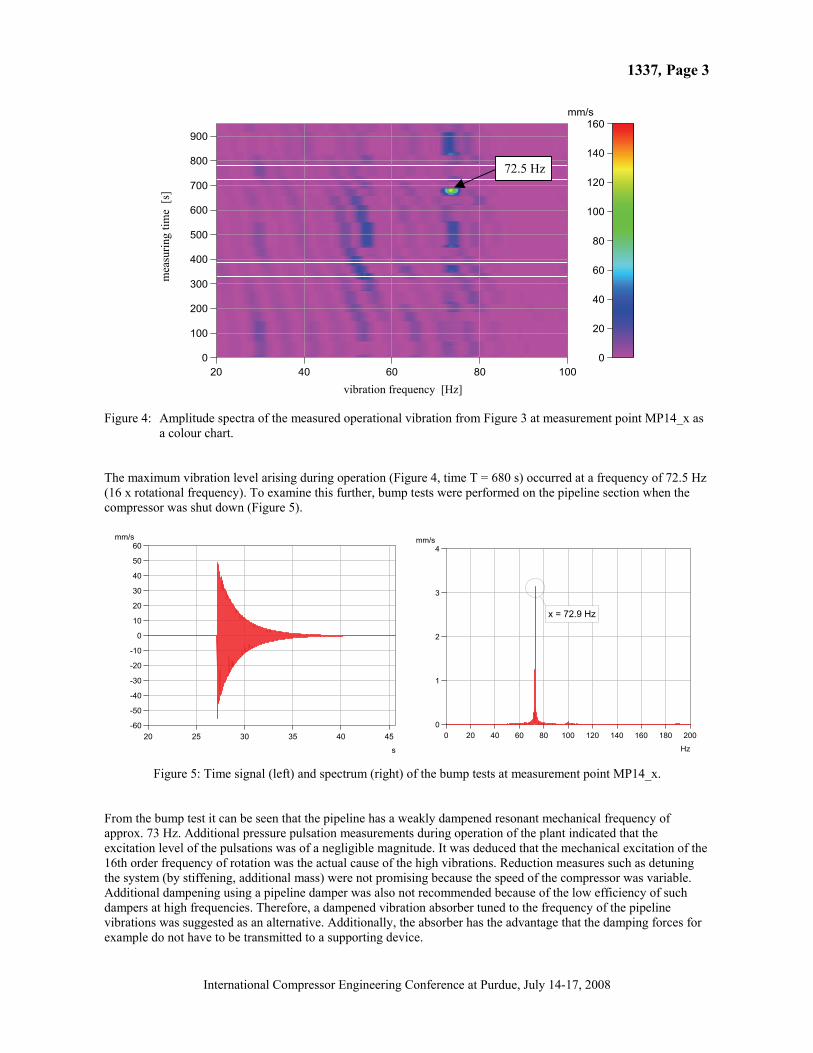
Figure 4: Amplitude spectra of the measured operational vibration from Figure 3 at measurement point MP14_x as a colour chart.
The maximum vibration level arising during operation (Figure 4, time T = 680 s) occurred at a frequency of 72.5 Hz (16 x rotational frequency). To examine this further, bump tests were performed on the pipeline section when the compressor was shut down (Figure 5).
Figure 5: Time signal (left) and spectrum (right) of the bump tests at measurement point MP14_x. From the bump test it can be seen that the pipeline has a weakly dampened resonant mechanical frequency of approx. 73 Hz. Additional pressure pulsation measurements during operation of the plant indicated that the excitation level of the pulsations was of a negligible magnitude. It was deduced that the mechanical excitation of the 16th order frequency of rotation was the actual cause of the high vibrations. Reduction measures such as detuning the system (by stiffening, additional mass) were not promising because the speed of the compressor was variable. Additional dampening using a pipeline damper was also not recommended because of the low efficiency of such dampers at high frequencies. Therefore, a dampened vibration absorber tuned to the frequency of the pipeline vibrations was suggested as an alternative. Additionally, the absorber has the advantage that the damping forces for example do not have to be transmitted to a supporting device.
72.5 Hz m
easu
ring
time
[s]
vibration frequency [Hz]

1337, Page 4
International Compressor Engineering Conference at Purdue, July 14-17, 2008
3. THEORY OF THE VIBRATION ABSORBER
Vibration absorbers compensate the excitation forces using mass forces so that at certain frequencies individual points in the structure remain at rest or at least vibrate much less. There are two main types of vibration absorbers:
- standard vibration absorbers with a relatively small damping effect on harmonic excitation at a fixed or only slightly varying excitation frequency
- dampened vibration absorbers with a relatively large damping effect on excitations in a wide range of
frequencies. In the following, the theory of the vibration absorber will be explained using a simplified model without a detailed explanation of the corresponding mathematics. An oscillator with one degree of freedom will serve as simplified model to describe a vibration system.
Figure 6: Model of the one degree of freedom oscillator with the corresponding amplitude response. The model consists of a mass m, a spring with a rigidity c and a damper with a damping constant b. When the excitation matches the natural frequency of the system =
mc , the result is a high amplitude vibration
(resonance). To describe the dynamic, excitation-frequency-dependent response of the system, Figure 6 shows the amplitude response for the specified parameter values (m, c, b). With the help of this simplified model and the amplitude response, a number of vibration problems can be described. In the following, the method of operation of the absorber will be explained based on this model. A second vibration model is added to the one degree of freedom oscillator (Figure 7).
1337, Page 5
International Compressor Engineering Conference at Purdue, July 14-17, 2008
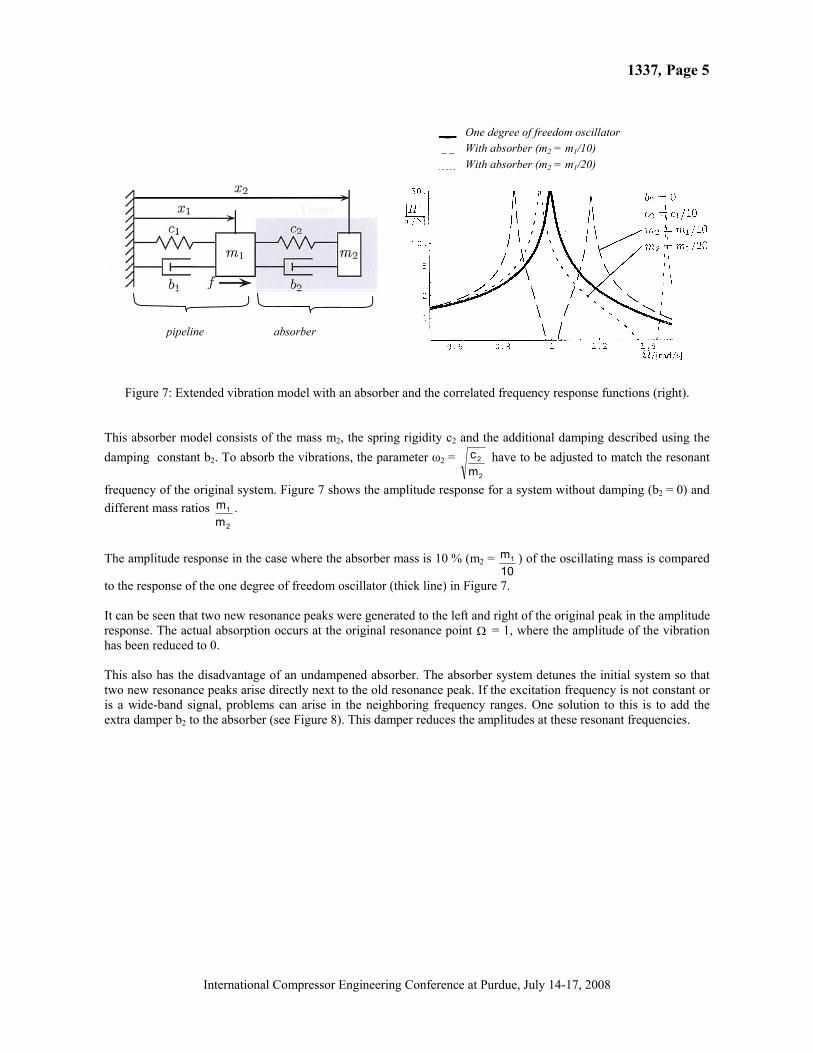
Figure 7: Extended vibration model with an absorber and the correlated frequency response functions (right).
This absorber model consists of the mass m2, the spring rigidity c2 and the additional damping described using the damping constant b2. To absorb the vibrations, the parameter 2 =
2
2
mc have to be adjusted to match the resonant
frequency of the original system. Figure 7 shows the amplitude response for a system without damping (b2 = 0) and different mass ratios
2
1
mm .
The amplitude response in the case where the absorber mass is 10 % (m2 =
10m1 ) of the oscillating mass is compared
to the response of the one degree of freedom oscillator (thick line) in Figure 7. It can be seen that two new resonance peaks were generated to the left and right of the original peak in the amplitude response. The actual absorption occurs at the original resonance point = 1, where the amplitude of the vibration has been reduced to 0. This also has the disadvantage of an undampened absorber. The absorber system detunes the initial system so that two new resonance peaks arise directly next to the old resonance peak. If the excitation frequency is not constant or is a wide-band signal, problems can arise in the neighboring frequency ranges. One solution to this is to add the extra damper b2 to the absorber (see Figure 8). This damper reduces the amplitudes at these resonant frequencies.
___ One degree of freedom oscillator With absorber (m2 = m1/10) With absorber (m2 = m1/20)
pipeline absorber

1337, Page 6
International Compressor Engineering Conference at Purdue, July 14-17, 2008
0
10
20
30
40
50
60
0,7 0,8 0,9 1,0 1,1 1,2 1,3
[-]
yT´ /
yst
at [
-]
b= 0 Ns/mb= 15 Ns/mb= 45 Ns/mb= 135 Ns/mb= 450 Ns/m
m2 = 2,32 kg
2 = 428,5 Hz b2
b2
b2
b2
b2
Figure 8: Amplitude response and the effect of different absorber damping values on the vibration response.
The higher the damping is selected, the lower are the neighboring resonance amplitude peaks, which means equally poorer vibration absorption at the old resonant location. The damping has to be adjusted for optimization purposes depending on the situation.
4. REALIZATION AND IMPLEMENTATION For the absorption of the pipeline vibrations at the often existing neighboring resonant frequencies on rotation-symmetric cross-sections, a three-dimensional vibration absorber (Figure 9) has been developed (Magic Cube).
Figure 9: Magic Cube – Three-dimensional dampened vibration absorber mounted on pipeline section DN = 100 mm (without housing cover).
1337, Page 7
International Compressor Engineering Conference at Purdue, July 14-17, 2008
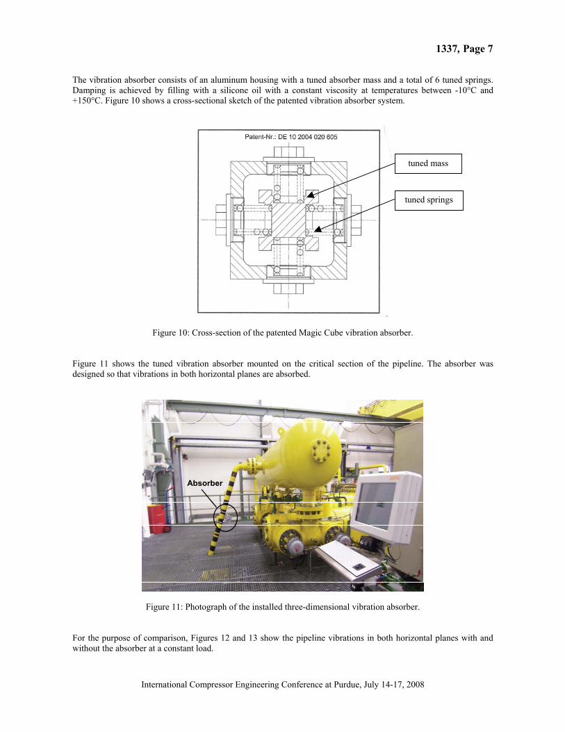
The vibration absorber consists of an aluminum housing with a tuned absorber mass and a total of 6 tuned springs. Damping is achieved by filling with a silicone oil with a constant viscosity at temperatures between -10°C and +150°C. Figure 10 shows a cross-sectional sketch of the patented vibration absorber system.
Figure 10: Cross-section of the patented Magic Cube vibration absorber.
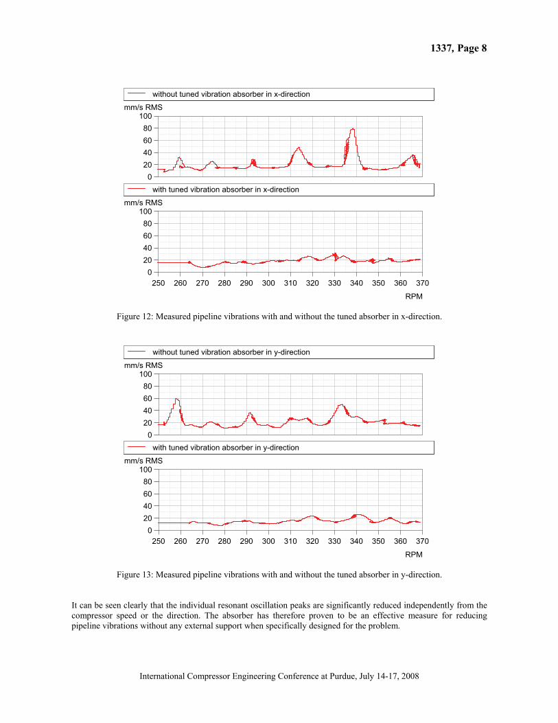
Figure 11 shows the tuned vibration absorber mounted on the critical section of the pipeline. The absorber was designed so that vibrations in both horizontal planes are absorbed.
AbsorberAbsorber
Figure 11: Photograph of the installed three-dimensional vibration absorber. For the purpose of comparison, Figures 12 and 13 show the pipeline vibrations in both horizontal planes with and without the absorber at a constant load.
tuned mass
tuned springs
1337, Page 8
International Compressor Engineering Conference at Purdue, July 14-17, 2008
without tuned vibration absorber in x-direction
020406080
100mm/s RMS
with tuned vibration absorber in x-direction
020406080
100mm/s RMS
250 260 270 280 290 300 310 320 330 340 350 360 370
RPM
Figure 12: Measured pipeline vibrations with and without the tuned absorber in x-direction.
without tuned vibration absorber in y-direction
020406080
100mm/s RMS
with tuned vibration absorber in y-direction
020406080
100mm/s RMS
250 260 270 280 290 300 310 320 330 340 350 360 370
RPM
Figure 13: Measured pipeline vibrations with and without the tuned absorber in y-direction. It can be seen clearly that the individual resonant oscillation peaks are significantly reduced independently from the compressor speed or the direction. The absorber has therefore proven to be an effective measure for reducing pipeline vibrations without any external support when specifically designed for the problem.