Magellan 2200VS/2200VSΩ and 2300HS/2300HSΩ · ii Magellan® 2200VS/2200VS ... Integrating the...
384
Magellan ® 2200VS/2200VSΩ and 2300HS/2300HSΩ Product Reference Guide
-
Upload
trankhuong -
Category
Documents
-
view
231 -
download
1
Transcript of Magellan 2200VS/2200VSΩ and 2300HS/2300HSΩ · ii Magellan® 2200VS/2200VS ... Integrating the...
Magellan® 2200VS/2200VSΩand 2300HS/2300HSΩ
Product Reference Guide
PSC Inc959 Terry Street Eugene, Oregon 97402 Telephone: (541) 683-5700 Fax: (541) 345-7140
An Unpublished Work - All rights reserved. No part of the contents of this documentation or the procedures described therein may be reproduced or transmitted in any form or by any means without prior written permission of PSC Inc. or its wholly owned subsidiaries ("PSC"). Owners of PSC products are hereby granted a non-exclusive, revocable license to reproduce and transmit this documentation for the purchaser's own internal business purposes. Purchaser shall not remove or alter any proprietary notices, including copyright notices, contained in this documentation and shall ensure that all notices appear on any reproduc-tions of the documentation.
Should future revisions of this manual be published, you can acquire printed versions by contacting your PSC representative. Electronic versions may either be downloadable from the PSC website (www.psc.com) or provided on appropriate media. If you visit our website and would like to make comments or suggestions about this or other PSC publications, please let us know via the “Contact PSC” page.
Disclaimer
PSC has taken reasonable measures to provide information in this manual that is complete and accurate, however, PSC reserves the right to change any specification at any time without prior notice.
PSC is a registered trademark of PSC Inc. The PSC logo is a trademark of PSC. All other trademarks and trade names referred to herein are property of their respective owners.
Magellan, FirstStrike and SurroundScan are registered trademarks of PSC Inc. All-Weighs, OmegaTek, Produce Rail, Productivity Index Report-ing, SmartSentry and Any-Weighs are all trademarks of PSC Inc.
This product may be covered by one or more of the following patents: 4603262 • 4639606 • 4652750 • 4672215 • 4699447 • 4709369 • 4749879 4786798 • 4792666 • 4794240 • 4798943 • 4799164 • 4820911 • 4845349 • 4861972 • 4861973 • 4866257 • 4868836 • 4879456 • 4939355 • 4939356 • 4943127 • 4963719 • 4971176 • 4971177 • 4991692 • 5001406 • 5015831 • 5019697 • 5019698 • 5086879 • 5115120 • 5144118 • 5146463 • 5179270 • 5198649 • 5200597 • 5202784 • 5208449 • 5210397 • 5212371 • 5212372 • 5214270 • 5229590 • 5231293 • 5232185 • 5233169 • 5235168 • 5237161 • 5237162 • 5239165 • 5247161 • 5256864 • 5258604 • 5258699 • 5260554 • 5274219 • 5296689 • 5298728 • 5311000 • 5327451 • 5329103 • 5330370 • 5347113 • 5347121 • 5371361 • 5382783 • 5386105 • 5389917 • 5410108 • 5420410 • 5422472 • 5426507 • 5438187 • 5440110 • 5440111 • 5446271 • 5446749 • 5448050 • 5463211 • 5475206 • 5475207 • 5479011 • 5481098 • 5491328 • 5493108 • 5504350 • 5508505 • 5512740 • 5541397 • 5552593 • 5557095 • 5563402 • 5565668 • 5576531 • 5581707 • 5594231 • 5594441 • 5598070 • 5602376 • 5608201 • 5608399 • 5612529 • 5629510 • 5635699 • 5641958 • 5646391 • 5661435 • 5664231 • 5666045 • 5671374 • 5675138 • 5682028 • 5686716 • 5696370 • 5703347 • 5705802 • 5714750 • 5717194 • 5723852 • 5750976 • 5767502 • 5770847 • 5786581 • 5786585 • 5787103 • 5789732 • 5796222 • 5804809 • 5814803 • 5814804 • 5821721 • 5822343 • 5825009 • 5834708 • 5834750 • 5837983 • 5837988 • 5852286 • 5864129 • 5869827 • 5874722 • 5883370 • 5905249 • 5907147 • 5923023 • 5925868 • 5929421 • 5945670 • 5959284 • 5962838 • 5979769 • 6000619 • 6006991 • 6012639 • 6016135 • 6024284 • 6041374 • 6042012 • 6045044 • 6047889 • 6047894 • 6056198 • 6065676 • 6069696 • 6073849 • 6073851 • 6094288 • 6112993 • 6129279 • 6129282 • 6134039 • 6142376 • 6152368 • 6152372 • 6155488 • 6166375 • 6169614 • 6173894 • 6176429 • 6188500 • 6189784 • 6213397 • 6223986 • 6230975 • 6230976 • 6237852 • 6244510 • 6259545 • 6260763 • 6266175 • 6273336 • 6276605 • 6279829 • 6290134 • 6290135 • 6293467 • 6303927 • 6311895 • 6318634 • 6328216 • 6332576 • 6332577 • 6343741 • 6454168 • 6478224 • 6568598 • 6578765 • 6705527 • 6974084 • 6991169 •7051940 • AU703547 • D312631 • D313590 • D320011 • D320012 • D323492 • D330707 • D330708 • D349109 • D350127 • D350735 • D351149 • D351150 • D352936 • D352937 • D352938 • D352939 • D358588 • D361565 • D372234 • D374630 • D374869 • D375493 • D376357 • D377345 • D377346 • D377347 • D377348 • D388075 • D446524 • EP0256296 • EP0260155 • EP0260156 • EP0295936 • EP0325469 • EP0349770 • EP0368254 • EP0442215 • EP0498366 • EP0531645 • EP0663643 • EP0698251 • GB2252333 • GB2284086 • GB2301691 • GB2304954 • GB2307093 • GB2308267 • GB2308678 • GB2319103 • GB2333163 • GB2343079 • GB2344486 • GB2345568 • GB2354340 • ISR107546 • ISR118507 • ISR118508 • JP1962823 • JP1971216 • JP2513442 • JP2732459 • JP2829331 • JP2953593 • JP2964278 • MEX185552 • MEX187245 • RE37166 • Other Patents Pending

Product Reference Guide i
Table of Contents
Chapter 1. Introduction .................................................................................... 1-1Manual Overview ...........................................................................................1-1
How to Use This Manual ............................................................................1-2Scanner Nomenclature ...................................................................................1-3
Connectors ..............................................................................................1-4Physical Parameters .......................................................................................1-5
Scanning ................................................................................................1-5AC Adapter .............................................................................................1-5
Electrical Specifications ..................................................................................1-6Power Supply ..........................................................................................1-7
Laser and Product Safety ................................................................................1-8Labeling ..................................................................................................... 1-10Agency Compliances .................................................................................... 1-12Bar Codes Supported ................................................................................... 1-13
Chapter 2. Site Preparation and Installation..................................................... 2-1Unpacking ....................................................................................................2-1Operational Verification ..................................................................................2-2Installation: Model 2200VS .............................................................................2-3Installation: Model 2300HS .............................................................................2-6
Chapter 3. Operation and Maintenance............................................................. 3-1Scanning Items: Model 2200VS .......................................................................3-2Scanning Items: Model 2300HS .......................................................................3-3Operational Controls ......................................................................................3-4Operational Modes .........................................................................................3-4
Power-Up/Selftest & Pre-Operation .............................................................3-4Operating Mode .......................................................................................3-5
Additional Functions .......................................................................................3-7Programming ..........................................................................................3-7Scanner Diagnostic Mode ..........................................................................3-7Scanner Reset .........................................................................................3-8
Operational Maintenance ................................................................................3-8Cleaning .................................................................................................3-8
Chapter 4. Problem Isolation............................................................................ 4-1Diagnostic Procedures ....................................................................................4-2Error Codes ..................................................................................................4-3Flowcharts ....................................................................................................4-4
ii Magellan® 2200VS/2200VSΩ and 2300HS/2300HSΩ
Chapter 5. Programming .................................................................................. 5-1Introduction to Label Programming .................................................................. 5-1Understanding the Basics ............................................................................... 5-1Integrating the Scanner With Your Host System ................................................ 5-1
Customizing Your Scanner’s Operation ....................................................... 5-2Programming Overview .................................................................................. 5-3
Programming via Handheld Device ............................................................. 5-4What Is Programming Mode? .................................................................... 5-4Entering and Exiting Programming Mode. .................................................... 5-4Programming Session .............................................................................. 5-5
LED and Beeper Indicators ............................................................................. 5-9If You Make a Mistake... ................................................................................. 5-9
Return to Factory Settings ........................................................................ 5-9Test Mode .............................................................................................5-10
General Scanner Features .............................................................................5-11Double Read Timeout ..............................................................................5-11Laser Timeout ........................................................................................5-13Motor Timeout .......................................................................................5-15Green LED Idle State ..............................................................................5-18Scanner Button Options ...........................................................................5-19Power-up Beep Control ............................................................................5-21Good Read Beep Control ..........................................................................5-23Good Read Beep Frequency .....................................................................5-24Good Read Beep Length ..........................................................................5-26Good Read Beep Volume .........................................................................5-27Good Read When to Indicate ....................................................................5-30EAS Active State ....................................................................................5-32EAS Timeout ..........................................................................................5-33Aux Port Mode .......................................................................................5-34Productivity Index Reporting (PIR) ............................................................5-36
Interface Related Features ............................................................................5-37Interface Type .......................................................................................5-37Maximum Host-Transmitted Message Length ..............................................5-51Number of Host Transmission Buffers ........................................................5-52Global Prefix ..........................................................................................5-53Global Suffix ..........................................................................................5-55
IBM Features ...............................................................................................5-57IBM Transmit Labels in Code 39 Format .....................................................5-57IBM USB Scanner Device Type .................................................................5-58
RS-232 Features ..........................................................................................5-59RS-232 Baud Rate ..................................................................................5-59RS-232 Number of Data Bits ....................................................................5-63RS-232 Number of Stop Bits ....................................................................5-64RS-232 Parity ........................................................................................5-65RS-232 Hardware Control ........................................................................5-67RS-232 Intercharacter Delay ....................................................................5-69RS-232 Software Flow Control ..................................................................5-70
Product Reference Guide iii
RS-232 Host Echo .................................................................................. 5-71RS-232 Host Echo Quiet Interval .............................................................. 5-72RS-232 Ignore Host Commands ............................................................... 5-73RS-232 TTL ........................................................................................... 5-74RS-232 TTL Invert ................................................................................. 5-75RS-232 Beep on ASCII BEL ..................................................................... 5-76RS-232 Beep on Not on File ..................................................................... 5-77RS-232 ACK NAK Enable ......................................................................... 5-78RS-232 ACK Character ............................................................................ 5-80RS-232 NAK Character ............................................................................ 5-81RS-232 Retry on ACK NAK Timeout .......................................................... 5-82RS-232 ACK NAK Timeout Value .............................................................. 5-83RS-232 ACK NAK Retry Count .................................................................. 5-84RS-232 ACK NAK Error Handling .............................................................. 5-85RS-232 Label ID Control ......................................................................... 5-87
Single Cable RS-232 Options ......................................................................... 5-89Single Cable RS-232 RTS CTS Selection .................................................... 5-90Single Cable RS-232 Use BCC .................................................................. 5-93Single Cable RS-232 Use ACK/NAK ........................................................... 5-94Single Cable RS-232 Use STX .................................................................. 5-95Set Single Cable RS-232 STX Character .................................................... 5-96Single Cable RS-232 Use ETX .................................................................. 5-97Set Single Cable RS-232 ETX Character .................................................... 5-98
PC Keyboard Wedge and USB Keyboard Interfaces ........................................... 5-99Connect to a Laptop/No Keyboard Attached ............................................. 5-100Send Control/Function Characters — continued ........................................ 5-102Caps Lock — continued ......................................................................... 5-104Country Mode ...................................................................................... 5-105Keyboard Wedge Intercharacter Delay .................................................... 5-115Quiet Interval ...................................................................................... 5-119
Symbology Programming ............................................................................ 5-123UPC-A Enable ............................................................................................ 5-123
UPC-A Number System Character Transmission ........................................ 5-124UPC-A Check Character Transmission ..................................................... 5-125Expand UPC-A to EAN-13 ...................................................................... 5-126UPC/EAN AIM ID .................................................................................. 5-127UPC-A Label ID .................................................................................... 5-128UPC-A 2-Digit Supplemental Label ID ...................................................... 5-129UPC-A 5-Digit Supplemental Label ID ...................................................... 5-130UPC-A 128 Supplemental Label ID .......................................................... 5-131
UPC-E Enable ............................................................................................ 5-132UPC-E Number System Character Transmission ........................................ 5-133UPC-E Check Character Transmission ...................................................... 5-134Expand UPC-E to UPC-A ........................................................................ 5-135Expand UPC-E to EAN-13 ...................................................................... 5-136UPC-E Label ID .................................................................................... 5-137UPC-E 2-Digit Supplemental Label ID ...................................................... 5-138
iv Magellan® 2200VS/2200VSΩ and 2300HS/2300HSΩ
UPC-E 5-Digit Supplemental Label ID ......................................................5-139UPC-E 128 Supplemental Label ID ..........................................................5-140
EAN-13 Enable ..........................................................................................5-141EAN-13 First Character Transmission .......................................................5-142EAN-13 Check Character Transmission ....................................................5-143EAN-13 ISBN Conversion Enable .............................................................5-144EAN 13 Label ID ...................................................................................5-145EAN-13 2-Digit Supplemental Label ID ....................................................5-146EAN-13 5-Digit Supplemental Label ID ....................................................5-147EAN-13 128 Supplemental Label ID ........................................................5-148Bookland AIM ID ..................................................................................5-149Bookland Label ID ................................................................................5-150
EAN-8 Enable ............................................................................................5-151EAN-8 Check Character Transmission ......................................................5-152Expand EAN-8 to EAN-13 .......................................................................5-153EAN 8 Label ID .....................................................................................5-154EAN-8 2-Digit Supplemental Label ID ......................................................5-155EAN-8 5-Digit Supplemental Label ID ......................................................5-156EAN-8 128 Supplemental Label ID ..........................................................5-157EAN-8 Decoding Levels ..........................................................................5-158
Other UPC/EAN Options ..............................................................................5-161UPC/EAN Reconstruction ........................................................................5-162Price Weight Check ...............................................................................5-163Enable EAN Two Label ...........................................................................5-166Addons ...............................................................................................5-167UPC-A and EAN-13 Decoding Levels ........................................................5-169
GTIN Enable ..............................................................................................5-172GTIN Label ID ......................................................................................5-173GTIN 2-Digit Supplemental Label ID ........................................................5-174GTIN 5-Digit Supplemental Label ID ........................................................5-175GTIN Code 128 Supplemental Label ID ....................................................5-176
RSS-14 Enable ..........................................................................................5-177RSS-14 Check Character Transmission ....................................................5-178RSS-14/EAN-128 Emulation ...................................................................5-179RSS-14 2D Component Enable ...............................................................5-180RSS-14 AIM ID .....................................................................................5-181RSS-14 Label ID ...................................................................................5-182
RSS Expanded Enable .................................................................................5-183RSS Expanded EAN-128 Emulation .........................................................5-184RSS Expanded 2D Component Enable ......................................................5-185RSS Expanded AIM ID ...........................................................................5-186RSS Expanded Label ID .........................................................................5-187RSS Expanded Length Control ................................................................5-188RSS Expanded Maximum Label Length ....................................................5-189RSS Expanded Minimum Label Length .....................................................5-190RSS Expanded Fixed Length 1 ................................................................5-191RSS Expanded Fixed Length 2 ................................................................5-192
Product Reference Guide v
Code 39 Enable ......................................................................................... 5-193Code 39 Start Stop Character Transmission ............................................. 5-194Code 39 Check Character Calculation ...................................................... 5-195Code 39 Check Character Transmission ................................................... 5-196Code 39 Full ASCII ............................................................................... 5-197Code 39 AIM ID ................................................................................... 5-198Code 39 Label ID ................................................................................. 5-199Code 39 Length Control ........................................................................ 5-200Code 39 Maximum Label Length ............................................................. 5-201Code 39 Minimum Label Length ............................................................. 5-202Code 39 Fixed Length 1 ........................................................................ 5-203Code 39 Fixed Length 2 ........................................................................ 5-204Code 39 Stitching ................................................................................ 5-205
Pharmacode 39 Enable ............................................................................... 5-206Pharmacode 39 Start Stop Character Transmission ................................... 5-207Pharmacode 39 Check Character Transmission ......................................... 5-208Pharmacode 39 Label ID ....................................................................... 5-209
Code 128 Enable ....................................................................................... 5-210Code 128 Transmit Function Characters .................................................. 5-211Convert Code 128 to Code 39 ................................................................ 5-212Code 128 AIM ID ................................................................................. 5-213Code 128 Label ID ............................................................................... 5-214Code 128 Length Control ....................................................................... 5-215Code 128 Maximum Label Length ........................................................... 5-216Code 128 Minimum Label Length ............................................................ 5-217Code 128 Fixed Length 1 ...................................................................... 5-218Code 128 Fixed Length 2 ...................................................................... 5-219Code 128 Stitching ............................................................................... 5-220
EAN-128 Enable ........................................................................................ 5-221EAN 128 AIM ID ................................................................................... 5-222EAN 128 Label ID ................................................................................. 5-223
Interleaved 2 of 5 (I 2 OF 5) Enable ............................................................. 5-224I 2 of 5 Check Character Calculation ....................................................... 5-225I 2 of 5 Check Character Transmission .................................................... 5-226I 2 of 5 AIM ID .................................................................................... 5-227I 2 of 5 Label ID .................................................................................. 5-228I 2 of 5 Length Control ......................................................................... 5-229I 2 of 5 Maximum Label Length .............................................................. 5-230I 2 of 5 Minimum Label Length ............................................................... 5-231I 2 of 5 Fixed Length 1 ......................................................................... 5-232I 2 of 5 Fixed Length 2 ......................................................................... 5-233I 2 of 5 Stitching .................................................................................. 5-234
Codabar Enable ......................................................................................... 5-235Codabar Start Stop Character Transmission ............................................. 5-236Codabar Start Stop Character Set .......................................................... 5-237Codabar Start Stop Character Match ....................................................... 5-239Codabar Check Character Calculation ...................................................... 5-240
vi Magellan® 2200VS/2200VSΩ and 2300HS/2300HSΩ
Codabar Check Character Transmission ...................................................5-241Codabar AIM ID ...................................................................................5-242Codabar Label ID ..................................................................................5-243Codabar Length Control .........................................................................5-244Codabar Maximum Label Length .............................................................5-245Codabar Minimum Label Length ..............................................................5-246Codabar Fixed Length 1 .........................................................................5-247Codabar Fixed Length 2 .........................................................................5-248Codabar Stitching .................................................................................5-249
Code 93 Enable .........................................................................................5-250Code 93 AIM ID ....................................................................................5-251Code 93 Label ID ..................................................................................5-252Code 93 Length Control .........................................................................5-253Code 93 Maximum Label Length .............................................................5-254Code 93 Minimum Label Length ..............................................................5-255Code 93 Fixed Length 1 .........................................................................5-256Code 93 Fixed Length 2 .........................................................................5-257Code 93 Stitching .................................................................................5-258
MSI/Plessey Enable ....................................................................................5-259MSI/Plessey Check Character Calculation .................................................5-260MSI/Plessey Number of Check Characters ................................................5-261MSI/Plessey Check Character Transmission ..............................................5-262MSI/Plessey AIM ID ..............................................................................5-263MSI/Plessey Label ID ............................................................................5-264MSI/Plessey Length Control ...................................................................5-265MSI/Plessey Maximum Label Length ........................................................5-266MSI/Plessey Minimum Label Length ........................................................5-267MSI/Plessey Fixed Length 1 ...................................................................5-268MSI/Plessey Fixed Length 2 ...................................................................5-269MSI/Plessey Stitching ............................................................................5-270
Standard 2 of 5 Enable ...............................................................................5-271Standard 2 of 5 Check Character Calculation ............................................5-272Standard 2 of 5 Check Character Transmission .........................................5-273Standard 2 of 5 AIM ID .........................................................................5-274Standard 2 of 5 Label ID .......................................................................5-275Standard 2 of 5 Length Control ...............................................................5-276Standard 2 of 5 Maximum Label Length ...................................................5-277Standard 2 of 5 Minimum Label Length ....................................................5-278Standard 2 of 5 Fixed Length 1 ..............................................................5-279Standard 2 of 5 Fixed Length 2 ..............................................................5-280Standard 2 of 5 Stitching .......................................................................5-281
Appendix A. LED/Beeper Indications & Controls ................................. A-1Volume/Tone Push Button ........................................................................ A-2Green LED Indicator ................................................................................. A-3
Product Reference Guide vii
Appendix B. Cable Information............................................................ B-1
Appendix C. Keypad............................................................................. C-1
Appendix D. Host Commands............................................................... D-1
Appendix E. Factory Defaults............................................................... E-1
Appendix F. Handheld Data Format Requirements............................... F-1Handheld Data Format Requirements General .............................................. F-1PSC Handheld Data Format Requirements ................................................... F-2AIM Formats ......................................................................................... F-10

viii Magellan® 2200VS/2200VSΩ and 2300HS/2300HSΩ
Product Reference Guide 1-1
Chapter 1
Introduction
This Product Reference Guide contains comprehensive instructions on how to install the scanner, how to program it using special programming feature bar code labels, and advanced user information as described in the following overview.
Manual OverviewChapter 1, Introduction, presents the manual’s contents, describes features and specifications, provides regulatory and safety information, and lists the bar code symbologies the scanner will read.
Chapter 2, Site Preparation and Installation, supplies physical dimen-sions for the scanner and its most common accessories, and details counter preparation and installation. Cable routing, connection and testing are also explained in this section.
Chapter 3, Operation and Maintenance, describes use and maintenance; providing details about operator controls, programming and diagnostic modes. Scanner routine maintenance is outlined in this section as well.
Chapter 4, Problem Isolation, provides an outline of three scanner test modes: Selftest, Operational Tests and Diagnostic Tests. Descriptions of the error indications if the scanner detects a system problem and trouble-shooting flowcharts to aid in problem resolution are also presented.
Chapter 5, Programming, details procedures and provides custom bar-codes for setting programmable scanner features. This section is organized by the categories: General Features, Interface Related Features and Sym-bology Related Features.
Appendix A, LED/Beeper Indications & Controls, lists the various func-tions and indications of the scanner control panel features.
Introduction
1-2 Magellan® 2200VS/2200VSΩ and 2300HS/2300HSΩ
Appendix B, Cable Information, outlines wire requirements, connector specifications and pinout details for associated product cabling.
Appendix C, Keypad, furnishes bar codes representing the digits and char-acters required to enter extended programming data needed during certain programming sessions.
Appendix D, Host Commands, contains a partial listing of available host commands that can be used with a compatible host interface.
Appendix E, Factory Defaults, is a listing of standard factory defaults for the various programmable features.
Appendix F, Handheld Data Format Requirements, provides application notes to describe the general format of data that can be accepted by the scanner through the auxiliary port as transmitted from a handheld scan-ner.
How to Use This ManualYou’ll find it helpful to familiarize yourself with the first section of this manual, since it provides both a general description of the product’s fea-tures and an overview of the manual’s contents and organization. Refer-ence the other sections as required for information about scanner installation, operation, maintenance and bar code programming.
Scanner Nomenclature
Product Reference Guide 1-3
Manual Conventions
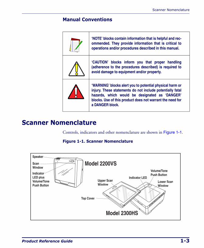
Scanner NomenclatureControls, indicators and other nomenclature are shown in Figure 1-1.
Figure 1-1. Scanner Nomenclature
‘NOTE’ blocks contain information that is helpful and rec-ommended. They provide information that is critical to operations and/or procedures described in this manual.
‘CAUTION’ blocks inform you that proper handling (adherence to the procedures described) is required to avoid damage to equipment and/or property.
‘WARNING’ blocks alert you to potential physical harm or injury. These statements do not include potentially fatal hazards, which would be designated as ‘DANGER’ blocks. Use of this product does not warrant the need for a DANGER block.
Speaker
ScanWindow
Upper ScanWindow
Lower ScanWindow
IndicatorLED plusVolume/TonePush Button
Volume/TonePush Button
Indicator LED
Model 2200VS
Model 2300HS
Top Cover
Introduction
1-4 Magellan® 2200VS/2200VSΩ and 2300HS/2300HSΩ
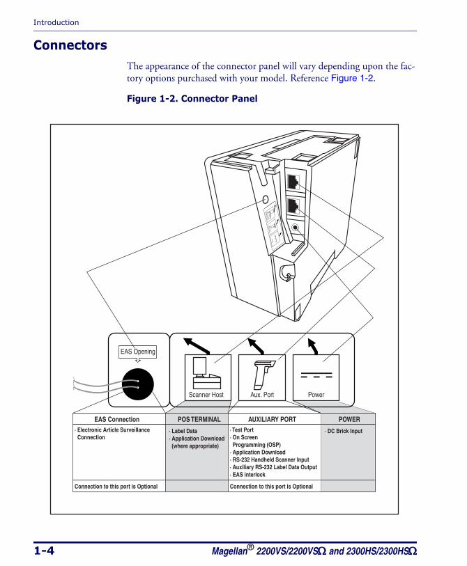
ConnectorsThe appearance of the connector panel will vary depending upon the fac-tory options purchased with your model. Reference Figure 1-2.
Figure 1-2. Connector Panel
POS TERMINAL AUXILIARY PORT POWER
Connection to this port is Optional
· DC Brick Input· Label Data· Application Download (where appropriate)
· Test Port· On Screen Programming (OSP)· Application Download· RS-232 Handheld Scanner Input· Auxiliary RS-232 Label Data Output· EAS interlock
EAS Connection
Connection to this port is Optional
· Electronic Article Surveillance Connection
Power
EAS Opening
Aux. PortScanner Host
Pow
er
Aux. P
ort
Scanner H
ost
Physical Parameters
Product Reference Guide 1-5
Physical ParametersThis section provides specifications for performance, environmental and electrical parameters. Reference the second section of this manual, Site Preparation and Installation, for physical measurements of all models and some accessories.
ScanningThe scanner has a scan zone immediately in front of (or above) the scan window where the scanner projects laser light in order to scan items. Scan lines form a zone where bar code labels are read. Refer to the Operation and Maintenance section of this manual for more details about the topic: Scanning Items: Model 2200VS.
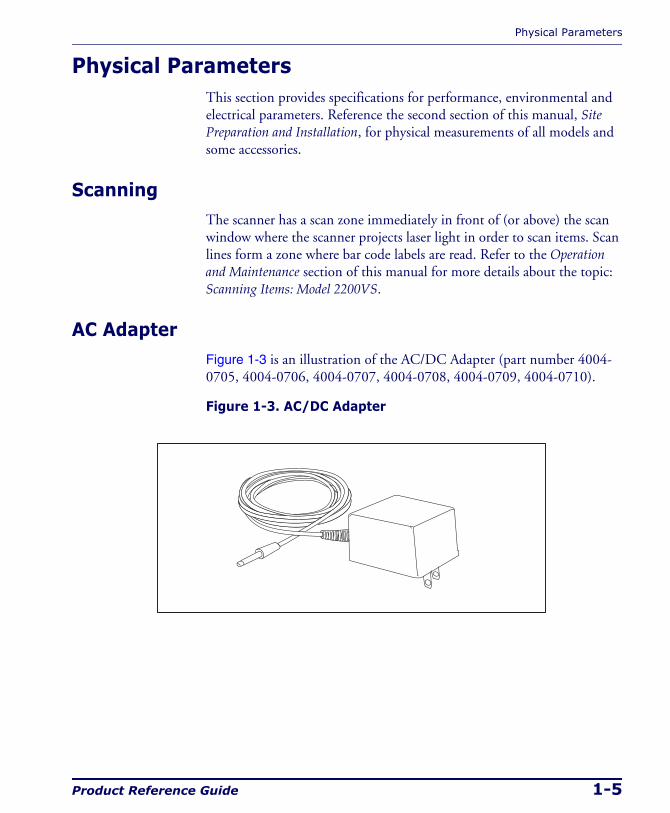
AC AdapterFigure 1-3 is an illustration of the AC/DC Adapter (part number 4004-0705, 4004-0706, 4004-0707, 4004-0708, 4004-0709, 4004-0710).
Figure 1-3. AC/DC Adapter
Introduction
1-6 Magellan® 2200VS/2200VSΩ and 2300HS/2300HSΩ
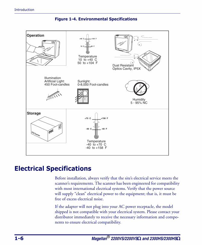
Figure 1-4. Environmental Specifications
Electrical SpecificationsBefore installation, always verify that the site’s electrical service meets the scanner’s requirements. The scanner has been engineered for compatibility with most international electrical systems. Verify that the power source will supply “clean” electrical power to the equipment; that is, it must be free of excess electrical noise.
If the adapter will not plug into your AC power receptacle, the model shipped is not compatible with your electrical system. Please contact your distributor immediately to receive the necessary information and compo-nents to ensure electrical compatibility.
Operation
Storage
+40 C +104 F
10 C 50 F
Temperature10 to +40 C50 to +104 F
Dust ResistantOptics Cavity, IP5X
+70 C +158 F
-40 C -40 F
Temperature-40 to +70 C-40 to +158 F
IlluminationArtificial Light:450 Foot-candles
Sunlight:0-8,000 Foot-candles
POS Scanner
Humidity5 - 95% NC
Electrical Specifications
Product Reference Guide 1-7
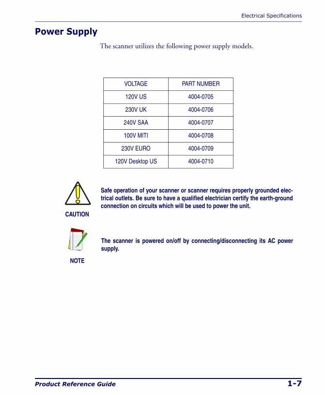
Power SupplyThe scanner utilizes the following power supply models.
VOLTAGE PART NUMBER
120V US 4004-0705
230V UK 4004-0706
240V SAA 4004-0707
100V MITI 4004-0708
230V EURO 4004-0709
120V Desktop US 4004-0710
CAUTION
Safe operation of your scanner or scanner requires properly grounded elec-trical outlets. Be sure to have a qualified electrician certify the earth-ground connection on circuits which will be used to power the unit.
NOTE
The scanner is powered on/off by connecting/disconnecting its AC power supply.

Introduction
1-8 Magellan® 2200VS/2200VSΩ and 2300HS/2300HSΩ
Laser and Product SafetyLaser safety requirements are based on IEC Standard Publication 60825-1 (2001) and CDRH 21CFR, Chapter 1, Subchapter J and (CDRH) Laser Product Performance Standard, User information [1040.10(h)1]:
• User Maintenance. No user maintenance of the system other than cleaning of the scan window(s) is required.
• Radiant Energy. The scanner is an IEC Class 1 and CDRH IIa laser product. The system uses two embedded Class 3R Visible Laser Diodes (VLDs) operating at 650.0 or 670.0 nm, in an opto-mechanical scanner, resulting in less than 3.9µW radiated power as observed through a 7mm aperture and averaged over 10 seconds. Maximum emitted peak output power at the window is 760µW. No attempt should be made by the user to remove the protective hous-ing of the scanner.
• Laser Light Viewing. The scan window is the only aperture through which laser light may be observed in this product.
Exposure to the light emitted from the scan window(s) has been shown not to be harmful. The safety record of bar code scanning is perfect after millions of hours of use worldwide. This safe and efficient use of laser technology has gained wide acceptance in industries throughout the world.
Operators and installers of the unit should observe the following cautions and warnings:
CAUTION
Use of controls, adjustments or performance of procedures other than those specified herein may result in hazardous laser light exposure.
The use of optical instruments with the scanner will increase eye hazard. (Optical instruments include binoculars, microscopes, telescopes and magni-fying glasses. This does not include eyeglasses worn by the user).
To prevent exposure to laser light, do not remove the protective housing of the scanner. There are no user-serviceable parts inside the unit.
Laser and Product Safety
Product Reference Guide 1-9
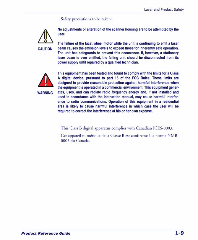
Safety precautions to be taken:
This Class B digital apparatus complies with Canadian ICES-0003.
Cet appareil numérique de la Classe B est confireme à la norme NMB-0003 du Canada.
CAUTION
No adjustments or alteration of the scanner housing are to be attempted by the user.
The failure of the facet wheel motor while the unit is continuing to emit a laser beam causes the emission levels to exceed those for inherently safe operation. The unit has safeguards to prevent this occurrence. If, however, a stationary laser beam is ever emitted, the failing unit should be disconnected from its power supply until repaired by a qualified technician.
WARNING
This equipment has been tested and found to comply with the limits for a Class A digital device, pursuant to part 15 of the FCC Rules. These limits are designed to provide reasonable protection against harmful interference when the equipment is operated in a commercial environment. This equipment gener-ates, uses, and can radiate radio frequency energy and, if not installed and used in accordance with the instruction manual, may cause harmful interfer-ence to radio communications. Operation of this equipment in a residential area is likely to cause harmful interference in which case the user will be required to correct the interference at his or her own expense.
Introduction
1-10 Magellan® 2200VS/2200VSΩ and 2300HS/2300HSΩ
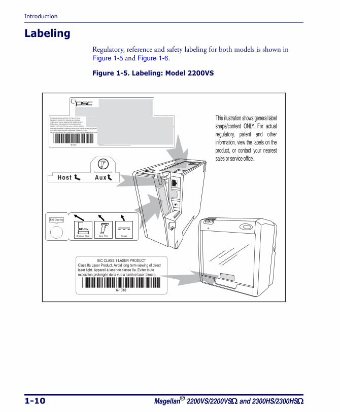
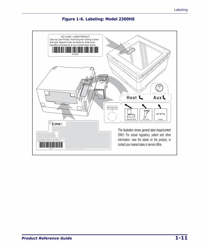
LabelingRegulatory, reference and safety labeling for both models is shown in Figure 1-5 and Figure 1-6.
Figure 1-5. Labeling: Model 2200VS
IEC CLASS 1 LASER PRODUCTClass IIa Laser Product. Avoid long term viewing of direct laser light. Appareil á laser de classe IIa. Eviter toute exposition prolongée de la vue à lumière laser directe.
6-1018
This device complies with Part 15 of the FCC Rules. Operation is subject to the following two conditions: (1) this device may not cause harmful interference, and (2) this device must accept any interference received, including interference that may cause undesired operation.
Output:+5V+12V
Use ONLY PSC INC. AC/DC Power Supply Input: 50 - 60 Hz (0.5 - 0.25A)
100 - 240VAC (P/N 8-0582)Power: 18 Watts (max)
THIS LASER PRODUCT COMPLIES WITH 21CFR 1040 AS APPLICABLE AS A CLASS IIA PRODUCTThis Class A digital apparatus complies with Canadian ICES-003.Cet appareil numérique de la Classe A est confirme à la norme NMB-003 du Canada.
N263
NRTL
Safety
tested
Production
monitored
PRODUCT SERVICE
Product of USA
U S
PSC Inc.959 Terry Street Eugene, OR 97402 USA
XXXXXXXXXXXX
CAUTION - CLASS 3R LASER RADIATION WHEN OPEN.AVOID DIRECT EYE EXPOSURE.
6-1012
COVERED BY ONE OR MORE OF THE FOLLOWING U.S. PATENTS: 4,709,195 4,709,369 4,712,853 4,749,879 4,786,798 4,792,666 4,798,943 4,799,164 4,816,660 4,861,972 4,861,973 4,866,257 4,868,836 4,879,456 4,963,719 4,991,692 5,144,118 5,179,270 5,198,649 5,247,162 5,229,588 5,410,108 5,459,308 5,440,110 5,475,207 5,493,108 5,705,802 5,723,852 5,834,708
This illustration shows general label shape/content ONLY. For actual regulatory, patent and other information, view the labels on the product, or contact your nearest sales or service office.
Host Aux
Scanner Host PowerAux. Port
EAS Opening
Labeling
Product Reference Guide 1-11
Figure 1-6. Labeling: Model 2300HS
IEC CLASS 1 LASER PRODUCTClass IIa Laser Product. Avoid long term viewing of direct laser light. Appareil á laser de classe IIa. Eviter toute exposition prolongée de la vue à lumière laser directe.
6-1018
This device complies with Part 15 of the FCC Rules. Operation is subject to the following two conditions: (1) this device may not cause harmful interference, and (2) this device must accept any interference received, including interference that may cause undesired operation.
Output:+5V+12V
Use ONLY PSC INC. AC/DC Power Supply Input: 50 - 60 Hz (0.5 - 0.25A)
100 - 240VAC (P/N 8-0582)Power: 18 Watts (max)
THIS LASER PRODUCT COMPLIES WITH 21CFR 1040 AS APPLICABLE AS A CLASS IIA PRODUCTThis Class A digital apparatus complies with Canadian ICES-003.Cet appareil numérique de la Classe A est confirme à la norme NMB-003 du Canada.
N263
NRTL
Safety
tested
Production
monitored
PRODUCT SERVICE
Product of USA
U S
PSC Inc.959 Terry Street Eugene, OR 97402 USA
XXXXXXXXXXXX
CAUTION - CLASS 3R LASER RADIATION WHEN OPEN.AVOID DIRECT EYE EXPOSURE.
6-1012
COVERED BY ONE OR MORE OF THE FOLLOWING U.S. PATENTS: 4,709,195 4,709,369 4,712,853 4,749,879 4,786,798 4,792,666 4,798,943 4,799,164 4,816,660 4,861,972 4,861,973 4,866,257 4,868,836 4,879,456 4,963,719 4,991,692 5,144,118 5,179,270 5,198,649 5,247,162 5,229,588 5,410,108 5,459,308 5,440,110 5,475,207 5,493,108 5,705,802 5,723,852 5,834,708
This illustration shows general label shape/content ONLY. For actual regulatory, patent and other information, view the labels on the product, or contact your nearest sales or service office.
Host Aux
Scanner Host PowerAux. Port
EAS Opening
Introduction
1-12 Magellan® 2200VS/2200VSΩ and 2300HS/2300HSΩ
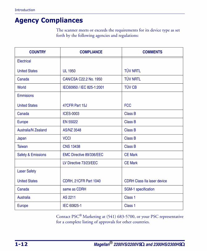
Agency CompliancesThe scanner meets or exceeds the requirements for its device type as set forth by the following agencies and regulations:
Contact PSC® Marketing at (541) 683-5700, or your PSC representative for a complete listing of approvals for other countries.
COUNTRY COMPLIANCE COMMENTS
Electrical
United States UL 1950 TÜV NRTL
Canada CAN/CSA C22.2 No. 1950 TÜV NRTL
World IEC60950 / IEC 825-1:2001 TÜV CB
Emmisions
United States 47CFR Part 15J FCC
Canada ICES-0003 Class B
Europe EN 55022 Class B
Australia/N Zealand AS/NZ 3548 Class B
Japan VCCI Class B
Taiwan CNS 13438 Class B
Safety & Emissions EMC Directive 89/336/EEC CE Mark
LV Directive 73/23/EEC CE Mark
Laser Safety
United States CDRH, 21CFR Part 1040 CDRH Class IIa laser device
Canada same as CDRH SGM-1 specification
Australia AS 2211 Class 1
Europe IEC 60825-1 Class 1
Bar Codes Supported
Product Reference Guide 1-13
Bar Codes SupportedThe scanner can read/decode the following bar code types (symbologies):
• UPC Versions A & E
• UPC Supplementals and Add-ons (2 & 5 digit supplementals and Code 128)
• Reduced Space Symbology (RSS) RSS-14 and RSS expanded; both support stacked component.
• EAN-8 & 13
• JAN-8 & 13
• EAN/JAN two label
• UCC/EAN 128
• Code 39
• Code 39 full ASCII
• Code 128 (including conversion to Code 39)
• Code 93
• Interleaved 2 of 5 (I 2 of 5)
• Italian Pharmacode (Code 39)
• Codabar
• Standard 2 of 5
• MSI/Plessey

Introduction
1-14 Magellan® 2200VS/2200VSΩ and 2300HS/2300HSΩ
NOTES

Unpacking
Product Reference Guide 2-1
Chapter 2
Site Preparation and Installation
This chapter outlines the procedures for unpacking the scanner, verifying function, preparing the countertop or wall, routing cables, and installing the scanner.
UnpackingTo unpack the unit:
• Inspect the package for signs of damage that may have occurred dur-ing shipping. If damage is found, report it to your carrier immedi-ately.
• Lift any accessories from the box, including the AC/DC Power Sup-ply, and the Quick Reference Guide.
• Familiarize yourself with the Quick Reference Guide. Leave the guide at the checkstand when the installation is complete.
• Remove the protective packing and carefully lift the scanner from the carton. Be sure to save the box and all packing material. In the event of failure, the unit must be returned to the factory in its origi-nal packaging.
Proceed to the Operational Verification instructions below.
Site Preparation and Installation
2-2 Magellan® 2200VS/2200VSΩ and 2300HS/2300HSΩ
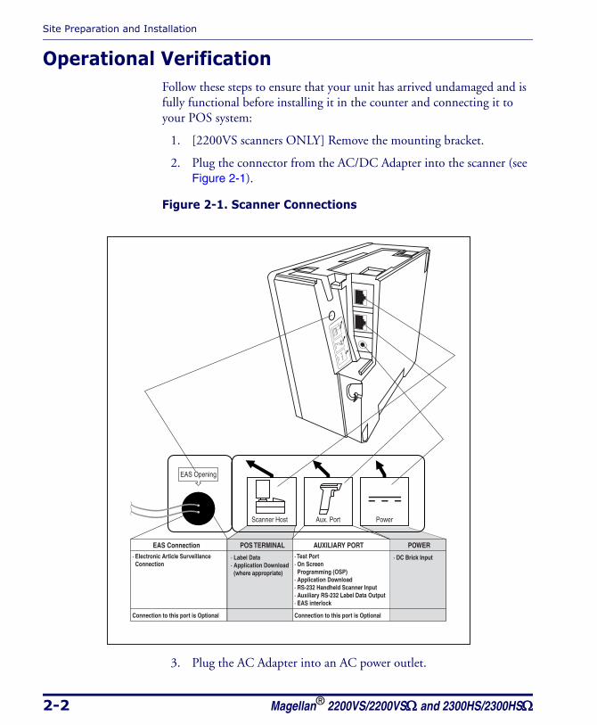
Operational VerificationFollow these steps to ensure that your unit has arrived undamaged and is fully functional before installing it in the counter and connecting it to your POS system:
1. [2200VS scanners ONLY] Remove the mounting bracket.
2. Plug the connector from the AC/DC Adapter into the scanner (see Figure 2-1).
Figure 2-1. Scanner Connections
3. Plug the AC Adapter into an AC power outlet.
POS TERMINAL AUXILIARY PORT POWER
Connection to this port is Optional
· DC Brick Input· Label Data· Application Download (where appropriate)
· Test Port· On Screen Programming (OSP)· Application Download· RS-232 Handheld Scanner Input· Auxiliary RS-232 Label Data Output· EAS interlock
EAS Connection
Connection to this port is Optional
· Electronic Article Surveillance Connection
Power
EAS Opening
Aux. PortScanner Host
Pow
er
Aux. P
ort
Scanner H
ost
Installation: Model 2200VS
Product Reference Guide 2-3
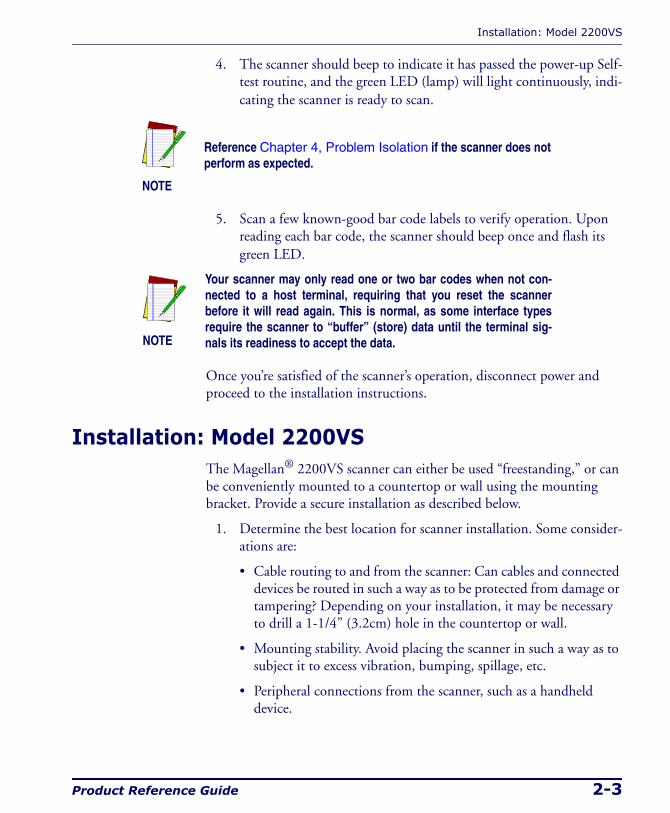
4. The scanner should beep to indicate it has passed the power-up Self-test routine, and the green LED (lamp) will light continuously, indi-cating the scanner is ready to scan.
5. Scan a few known-good bar code labels to verify operation. Upon reading each bar code, the scanner should beep once and flash its green LED.
Once you’re satisfied of the scanner’s operation, disconnect power and proceed to the installation instructions.
Installation: Model 2200VSThe Magellan® 2200VS scanner can either be used “freestanding,” or can be conveniently mounted to a countertop or wall using the mounting bracket. Provide a secure installation as described below.
1. Determine the best location for scanner installation. Some consider-ations are:
• Cable routing to and from the scanner: Can cables and connected devices be routed in such a way as to be protected from damage or tampering? Depending on your installation, it may be necessary to drill a 1-1/4” (3.2cm) hole in the countertop or wall.
• Mounting stability. Avoid placing the scanner in such a way as to subject it to excess vibration, bumping, spillage, etc.
• Peripheral connections from the scanner, such as a handheld device.
NOTE
Reference Chapter 4, Problem Isolation if the scanner does not perform as expected.
NOTE
Your scanner may only read one or two bar codes when not con-nected to a host terminal, requiring that you reset the scanner before it will read again. This is normal, as some interface types require the scanner to “buffer” (store) data until the terminal sig-nals its readiness to accept the data.
Site Preparation and Installation
2-4 Magellan® 2200VS/2200VSΩ and 2300HS/2300HSΩ
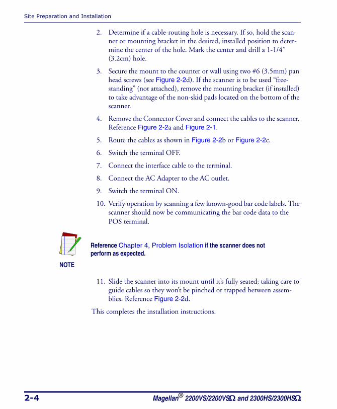
2. Determine if a cable-routing hole is necessary. If so, hold the scan-ner or mounting bracket in the desired, installed position to deter-mine the center of the hole. Mark the center and drill a 1-1/4” (3.2cm) hole.
3. Secure the mount to the counter or wall using two #6 (3.5mm) pan head screws (see Figure 2-2d). If the scanner is to be used “free-standing” (not attached), remove the mounting bracket (if installed) to take advantage of the non-skid pads located on the bottom of the scanner.
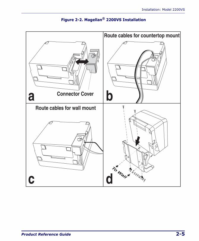
4. Remove the Connector Cover and connect the cables to the scanner. Reference Figure 2-2a and Figure 2-1.
5. Route the cables as shown in Figure 2-2b or Figure 2-2c.
6. Switch the terminal OFF.
7. Connect the interface cable to the terminal.
8. Connect the AC Adapter to the AC outlet.
9. Switch the terminal ON.
10. Verify operation by scanning a few known-good bar code labels. The scanner should now be communicating the bar code data to the POS terminal.
11. Slide the scanner into its mount until it’s fully seated; taking care to guide cables so they won’t be pinched or trapped between assem-blies. Reference Figure 2-2d.
This completes the installation instructions.
NOTE
Reference Chapter 4, Problem Isolation if the scanner does not perform as expected.
Installation: Model 2200VS
Product Reference Guide 2-5
Figure 2-2. Magellan® 2200VS Installation
a b
c d
Connector Cover
Route cables for countertop mount
Route cables for wall mount
To Countertop
To Wall
Site Preparation and Installation
2-6 Magellan® 2200VS/2200VSΩ and 2300HS/2300HSΩ
Installation: Model 2300HSThe Magellan® 2300HS scanner is mounted flush with the countertop to promote comfortable and ergonomic slide-through scanning. Installation as described below.
1. Determine the best location for scanner. Some considerations are:
• Proximity to the user. Verify that checkstand features allow the unit to be within easy reach of the user, without interfering with cash drawers or other equipment.
• Cable routing to and from the scanner: Can cables and connected devices be routed in such a way as to be protected from damage or tampering?
• Mounting stability. Avoid placing the scanner in such a way as to subject it to excess vibration, bumping, spillage, etc.
• Peripheral connections from the scanner, such as a handheld device.
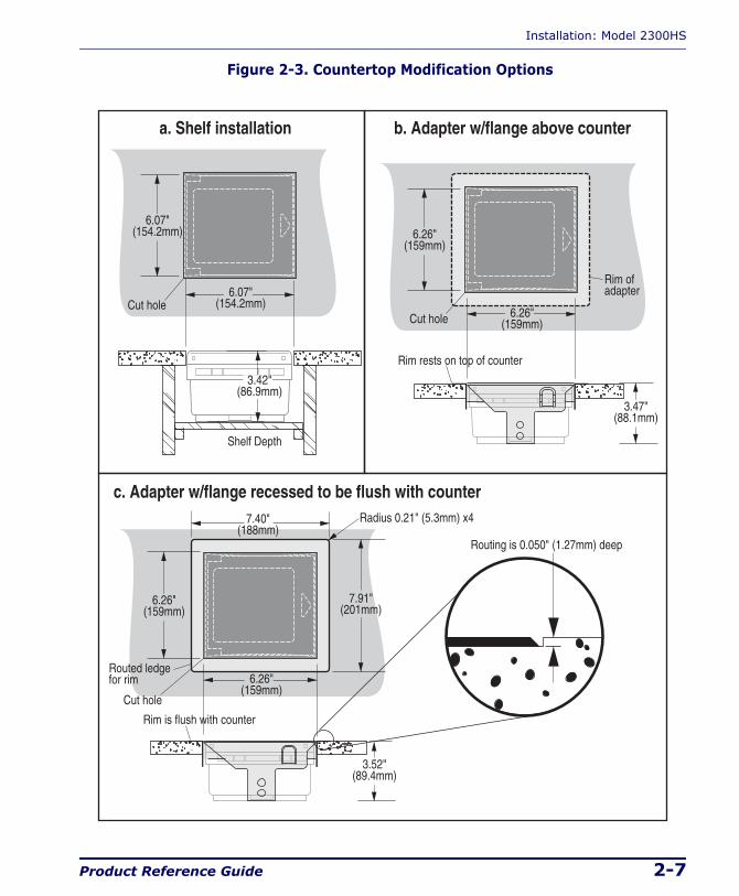
2. The countertop must be modified to accept the scanner. At the time of this writing, three options are available.
— Figure 2-3a shows the dimensions for the opening and other details if a shelf is to be built to support the unit.
— Figure 2-3b details the cutout dimensions if an adapter fixture holding the scanner will rest with its rim above the countertop.
— Figure 2-3c provides dimensions if an adapter fixture holding the scanner will be recessed to be flush with the countertop.
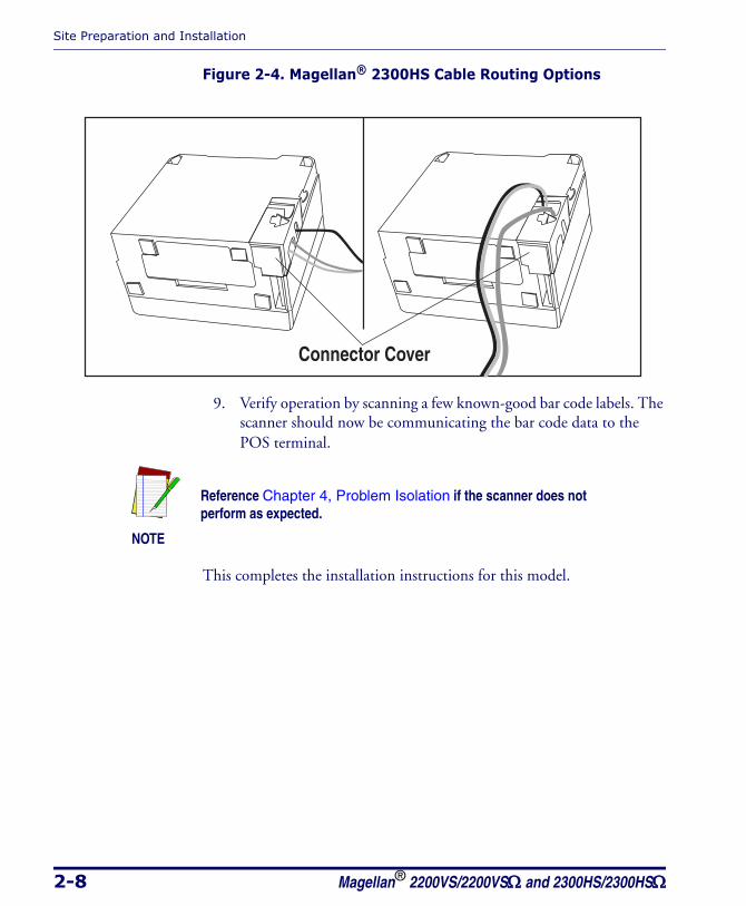
3. Remove the Connector Cover, then connect and route the cables at the scanner. Reference Figure 2-4.
4. Seat the scanner or in the countertop opening (or adapter).
5. Switch the terminal OFF.
6. Connect the interface cable to the terminal.
7. Connect the scanner’s AC Adapter to the AC outlet.
8. Switch the terminal ON.
Installation: Model 2300HS
Product Reference Guide 2-7
Figure 2-3. Countertop Modification Options
6.07"(154.2mm)
6.07"(154.2mm)
3.42"(86.9mm)
Shelf Depth
a. Shelf installation b. Adapter w/flange above counter
c. Adapter w/flange recessed to be flush with counter
6.26"(159mm)
3.47"(88.1mm)
Rim rests on top of counter
6.26"(159mm)
Rim is flush with counter
Cut hole
6.26"(159mm)
3.52"(89.4mm)
6.26"(159mm)
7.91"(201mm)
Routing is 0.050" (1.27mm) deep
Radius 0.21" (5.3mm) x4
Cut hole
Rim ofadapter
Cut hole
Routed ledgefor rim
7.40"(188mm)
Site Preparation and Installation
2-8 Magellan® 2200VS/2200VSΩ and 2300HS/2300HSΩ
Figure 2-4. Magellan® 2300HS Cable Routing Options
9. Verify operation by scanning a few known-good bar code labels. The scanner should now be communicating the bar code data to the POS terminal.
This completes the installation instructions for this model.
Connector Cover
NOTE
Reference Chapter 4, Problem Isolation if the scanner does not perform as expected.

Product Reference Guide 3-1
Chapter 3
Operation and Maintenance
The information contained in this section describes how to operate and maintain the scanner. Topics include scanning tips, and scan window cleaning and replacement.
Operation and Maintenance
3-2 Magellan® 2200VS/2200VSΩ and 2300HS/2300HSΩ
Scanning Items: Model 2200VSItem bar codes are scanned by either...
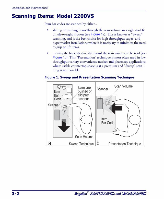
• sliding or pushing items through the scan volume in a right-to-left or left-to-right motion (see Figure 1a). This is known as “Sweep” scanning, and is the best choice for high throughput super- and hypermarket installations where it is necessary to minimize the need to grip or lift items.
• moving the bar code directly toward the scan window to be read (see Figure 1b). This “Presentation” technique is most often used in low throughput variety, convenience market and pharmacy applications where usable countertop space is at a premium and “Sweep” scan-ning is not possible.
Figure 1. Sweep and Presentation Scanning Technique
Scannera
ItemBar Code
ItemBarCode
Scan Volume
Scan VolumeItems arepushed orslid pastscanner
Scanner
a Sweep Technique Presentation Techniqueb
Scanning Items: Model 2300HS
Product Reference Guide 3-3
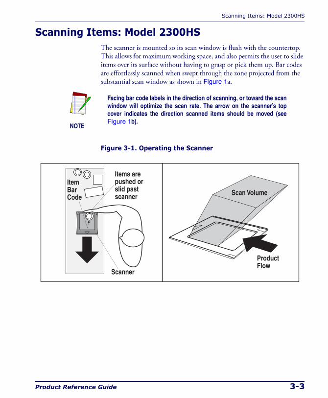
Scanning Items: Model 2300HSThe scanner is mounted so its scan window is flush with the countertop. This allows for maximum working space, and also permits the user to slide items over its surface without having to grasp or pick them up. Bar codes are effortlessly scanned when swept through the zone projected from the substantial scan window as shown in Figure 1a.
Figure 3-1. Operating the Scanner
NOTE
Facing bar code labels in the direction of scanning, or toward the scan window will optimize the scan rate. The arrow on the scanner’s top cover indicates the direction scanned items should be moved (see Figure 1b).
Scanner
ItemBarCode
Items arepushed orslid pastscanner
ProductFlow
Scan Volume
Operation and Maintenance
3-4 Magellan® 2200VS/2200VSΩ and 2300HS/2300HSΩ
Operational ControlsThe function of scanner controls and indicators is listed in Appendix A, LED/Beeper Indications & Controls. Turn to that appendix for full details.
Operational ModesThe scanner features a number of modes that are important to both the user and the system support personnel. These modes can be combined into three groups: pre-operational, operational; and additional functions. The following text describes these modes, what they mean, and how and when they are seen.
Power-Up/Selftest & Pre-Operation Pre-Operation describes those steps that must be successfully completed before the scanner sounds the initial good read tone and illuminates the LED (lamp) indicating readiness for operation. These steps include Power-Up Selftest, Error Reporting, and Operational Configuration.
Power-Up/Selftest
Power-Up Selftest begins when power is applied. The scanner’s software immediately begins the testing sequence to verify that all systems are func-tioning properly. This routine, which only takes a few seconds, checks all the functions of the scanner and interface prior to indicating that it is ready for operation.
NOTE
A tone indicating Selftest is complete is a configurable feature. See the topic Power-up Beep Control in Chapter 5 of this manual.
Operational Modes
Product Reference Guide 3-5
Error Reporting
If a fatal error is detected during Selftest or operation, the scanner will not advance to Normal Operation Mode. Selftest diagnostics will cause the scanner to sound a long, low tone. When this occurs, error codes may be accessed by momentarily pressing the Volume/Tone Push Button. The beeper and LED will then emit a coded series of indications to assist the repair technician in identifying the failed component. If an error is indi-cated, make note of the tones heard/LED flashes. A table containing a list-ing of the error codes is included in Chapter 4.
Operational Configuration
Once Selftest diagnostics have been successfully run, a tone is emitted (if configured to do so, and the unit enters an operational configuration state. The scanner will automatically load your specific interface settings which are required to communicate with the host system.
No bar code label can be in the scan volume while the unit is in this state. Progress is halted until the label has been removed, thereby ensuring that no extraneous bar code data is send to the host. When the scanner com-pletes its Selftest successfully, it emits a tone (when configured to do so) and enters Operating Mode.
Operating ModeOperating Mode includes Normal Operation (scanning) and Sleep Mode. These two modes are most commonly observed by the user/operator.
Normal Operation
This condition is indicated by the green light being on dim and steady.
NOTE
LED indications are configurable. Your scanner may not be pro-grammed to operate in the standard manner described above.
Operation and Maintenance
3-6 Magellan® 2200VS/2200VSΩ and 2300HS/2300HSΩ
Once the scanner enters Normal Operation, it begins a countdown sequence. If there is no activity during a preset period of time (also called time-out1), the unit will shut off the laser and/or motor in order to pro-long the life of the electrical and mechanical components. Once the scan-ner has timed out, it enters Sleep Mode.
Sleep Mode
After the scanner has been left idle for a preset period of time, the laser and/or motor automatically turns off (goes to sleep). This state is called Sleep Mode, and is indicated by a “slow” blink of the green light (blinking at a 2-second rate). To wake up the unit, press the Volume/Tone Push Button, wave your hand in front of the scan window, or scan an item using an attached auxiliary scanner (if present). The scanner will recognize these signals as a wake-up call and instantly return to Normal Operation.
1. “Timeout” and “Sleep Mode” time delays are programmable features that can be selected through use of the programming bar codes included in Chapter 5.
Additional Functions
Product Reference Guide 3-7
Additional FunctionsAdditional scanner functions include programming, running scanner diagnostics, or initiating a reset.
ProgrammingScanners are typically programmed at the factory to settings specified by the customer. Generally, POS system interface and bar code symbologies are pre-configured to operate in the target environment. Chapter 5 con-tains the necessary instructions, bar codes, and descriptions to program/reprogram scanner settings.
Scanner Diagnostic ModeWhile in Scanner Diagnostic Mode, continuous scanning of labels is allowed, permitting the user to scan an unlimited number of bar codes while troubleshooting problems. Under normal operation, the scanner stores label data, awaiting the signal which transmits it to the host. When the scanner is not connected to a host, it may read and store only up to two labels, then quit reading until power is cycled (clearing the memory). This mode of operation removes this limitation.
To place the scanner in Scanner Diagnostic Mode, press the Volume/Tone Push Button for approximately four seconds. While pressing the button, the scanner will first sound three tones, wait a few seconds, then sound six rapid tones; after which you should immediately release the button.
To exit Scanner Diagnostic Mode, cycle power to the scanner or press and hold the Volume/Tone Push Button for eight seconds to reset the scanner. See the topic, Scanner Reset, below for more information about scanner resets.
Turn to Chapter 4 for a description of error codes resulting from diagnos-tics.
Operation and Maintenance
3-8 Magellan® 2200VS/2200VSΩ and 2300HS/2300HSΩ
Scanner ResetAs with any electronic equipment, it is sometimes necessary to reset the electronics. The reset procedure allows you to initiate a reset command to the scanner. This may be necessary if the POS terminal has been switched off or the store system has been reset while the unit is on. Reset can also be used to initiate and run the scanner’s internal Selftest routine.
Pressing and holding the Volume/Tone Push Button for approximately eight seconds initiates a reset, which is sounded by a rapid number of beeps. If the motor had been spinning, the lamps will blink while the motor spins down. At that point, the motor will spin back up and the scanner will continue to run the Selftest diagnostics. For more informa-tion, see the topic, Power-Up/Selftest & Pre-Operation, earlier in this chapter.
Operational MaintenanceThe scanner will provide dependable service for many years. The follow-ing maintenance procedures will keep it operating at peak performance.
CleaningClean the exterior surface of the scan window at least twice daily with a nonabrasive, mild, water-based glass cleaner and paper towels or lint-free cleaning tissues. Textured plastic surfaces and stainless steel can also be cleaned using these cleaning agents.
Product Reference Guide 4-1
Chapter 4
Problem Isolation
In the event of a suspected functional problem, use the troubleshooting references provided in this section. This useful information will help you identify and resolve the cause of the problem.
The scanner incorporates features that indicate when a problem occurs. The scanner may:
• emit a series of tones
• flash the LED (lamp)
Three error reporting modes are used: Power-Up Selftest, Operational tests and Diagnostic tests. These test sequences are explained on the fol-lowing pages.
Power-Up Selftest
The Power-up Selftest is a pre-operational series of tests that must be suc-cessfully completed before the scanner indicates readiness for operation. This pre-operational period is the time between power-up and normal operation during which the motor comes up-to-speed and software, firm-ware and hardware are being tested. These tests ensure that all subsystems are fully functional before turning on the Visible Laser Diode (VLD). Refer to Chapter 3, Operational Modes, for a more detailed description of this and other scanner modes.
Operational Tests
These are the tests that run continually during Normal Operation and Sleep Mode. Firmware checks all subsystems, accessory connections as well as the POS interface to verify everything is operating normally. If a problem is detected at any time, a long, low tone is sounded and operation may be halted. If you press the Volume/Tone Push Button at that time, a series of tones will be sounded in concert with LED flashes.

Problem Isolation
4-2 Magellan® 2200VS/2200VSΩ and 2300HS/2300HSΩ
Diagnostic Tests
See Chapter 3, Scanner Diagnostic Mode for details about running diag-nostic tests for the scanner. If a problem is discovered during diagnostics, the scanner will provide feedback about the source of the problem. The remainder of this section describes these failure indications and includes troubleshooting flowcharts to help isolate the problem.
Diagnostic ProceduresYour Point-Of-Sale (POS) system may contain many components that operate as a system. Since almost all scanner problems are caused by either the scanner, POS terminal or communication links between them, trou-bleshooting flowcharts provided in this chapter focus on these compo-nents. Additionally, the AC/DC Power Supply and scanner cables are potential problems addressed.
The flowcharts provided here walk you through a diagnostic process that will isolate the failed component and instruct as to the corrective action required. Since internal scanner components cannot be replaced by an operator or installer, most functional errors will require the assistance of a trained technical support person. However, if the problem is caused by faulty cable, or power supply, you can fix the problem by replacing the defective component and complete the installation.
Error Codes
Product Reference Guide 4-3
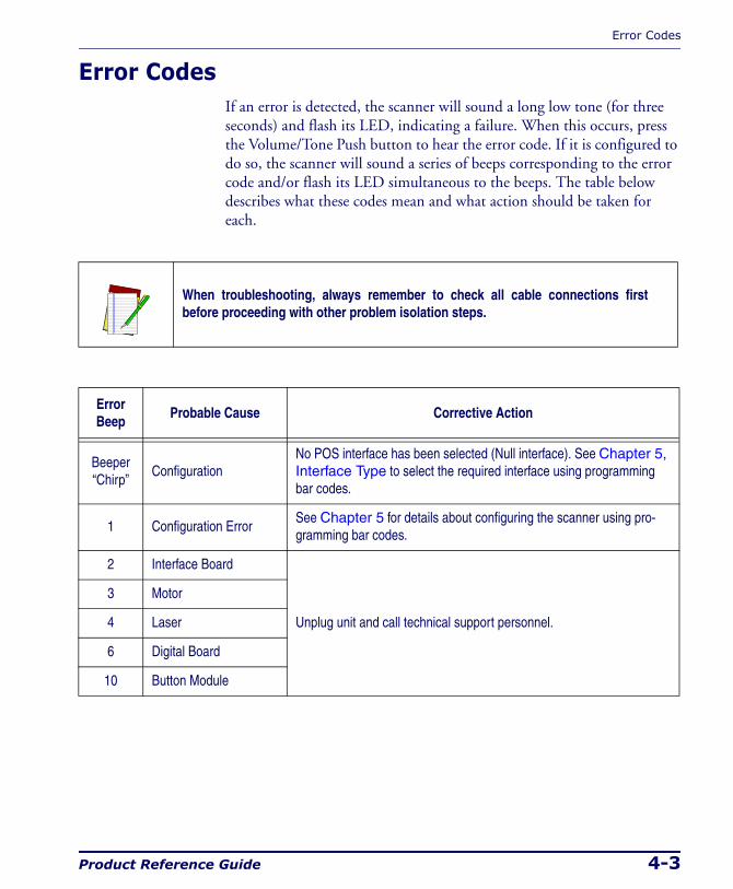
Error CodesIf an error is detected, the scanner will sound a long low tone (for three seconds) and flash its LED, indicating a failure. When this occurs, press the Volume/Tone Push button to hear the error code. If it is configured to do so, the scanner will sound a series of beeps corresponding to the error code and/or flash its LED simultaneous to the beeps. The table below describes what these codes mean and what action should be taken for each.
When troubleshooting, always remember to check all cable connections first before proceeding with other problem isolation steps.
Error Beep
Probable Cause Corrective Action
Beeper“Chirp”
ConfigurationNo POS interface has been selected (Null interface). See Chapter 5, Interface Type to select the required interface using programming bar codes.
1 Configuration ErrorSee Chapter 5 for details about configuring the scanner using pro-gramming bar codes.
2 Interface Board
Unplug unit and call technical support personnel.
3 Motor
4 Laser
6 Digital Board
10 Button Module
Problem Isolation
4-4 Magellan® 2200VS/2200VSΩ and 2300HS/2300HSΩ
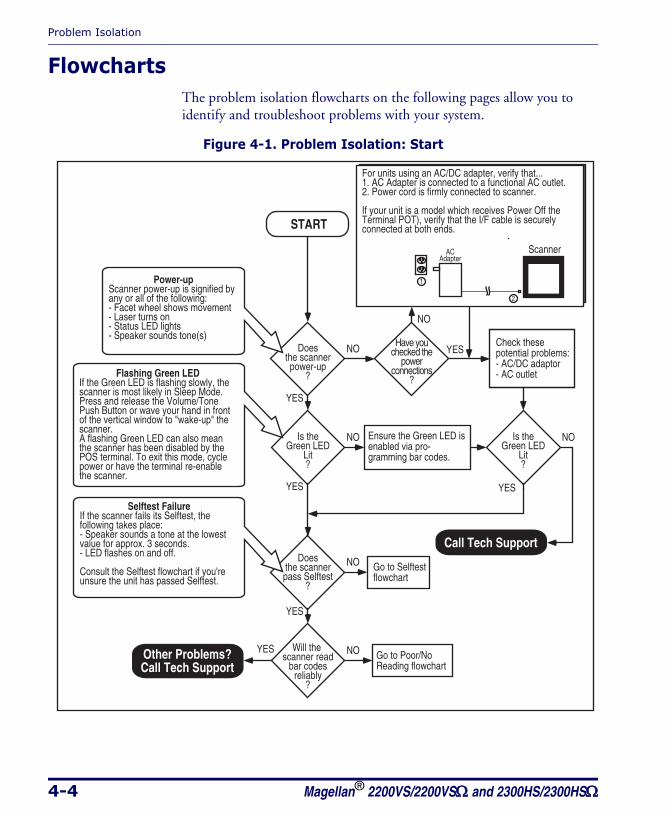
FlowchartsThe problem isolation flowcharts on the following pages allow you to identify and troubleshoot problems with your system.
Figure 4-1. Problem Isolation: Start
START
YES
NODoesthe scannerpower-up
?
YES
NODoesthe scannerpass Selftest
?
YES
NOIs theGreen LED
Lit?
YES
NOIs theGreen LED
Lit?
YES NOWill the scanner read
bar codesreliably
?
YES
NO
Have youchecked the
powerconnections
?
Check thesepotential problems:- AC/DC adaptor- AC outlet
Power-upScanner power-up is signified byany or all of the following:- Facet wheel shows movement- Laser turns on- Status LED lights- Speaker sounds tone(s)
Selftest FailureIf the scanner fails its Selftest, the following takes place:- Speaker sounds a tone at the lowest value for approx. 3 seconds.- LED flashes on and off.
Consult the Selftest flowchart if you're unsure the unit has passed Selftest.
Flashing Green LEDIf the Green LED is flashing slowly, the scanner is most likely in Sleep Mode. Press and release the Volume/Tone Push Button or wave your hand in front of the vertical window to "wake-up" the scanner.A flashing Green LED can also mean the scanner has been disabled by the POS terminal. To exit this mode, cycle power or have the terminal re-enable the scanner.
For units using an AC/DC adapter, verify that...1. AC Adapter is connected to a functional AC outlet.2. Power cord is firmly connected to scanner.
If your unit is a model which receives Power Off theTerminal POT), verify that the I/F cable is securelyconnected at both ends.
ACAdapter
Go to Selftestflowchart
Go to Poor/NoReading flowchart
Ensure the Green LED isenabled via pro-gramming bar codes.
Call Tech Support
Other Problems?Call Tech Support
Scanner
Flowcharts
Product Reference Guide 4-5
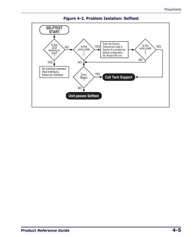
Figure 4-2. Problem Isolation: Selftest
Call Tech Support
NO
YESErrorBeeps
?
Unit passes Selftest
YES
NOIs theLED
blinking inerror
?
YES YES
NONO
Is theerror code
1?
Is theerror code
1?
SELFTESTSTART
No interface selected (Null Interface). Select an interface.
Scan the FactoryDefaults bar code inSection 6 to enable thedefault configurationfile. Restart the unit.
Problem Isolation
4-6 Magellan® 2200VS/2200VSΩ and 2300HS/2300HSΩ
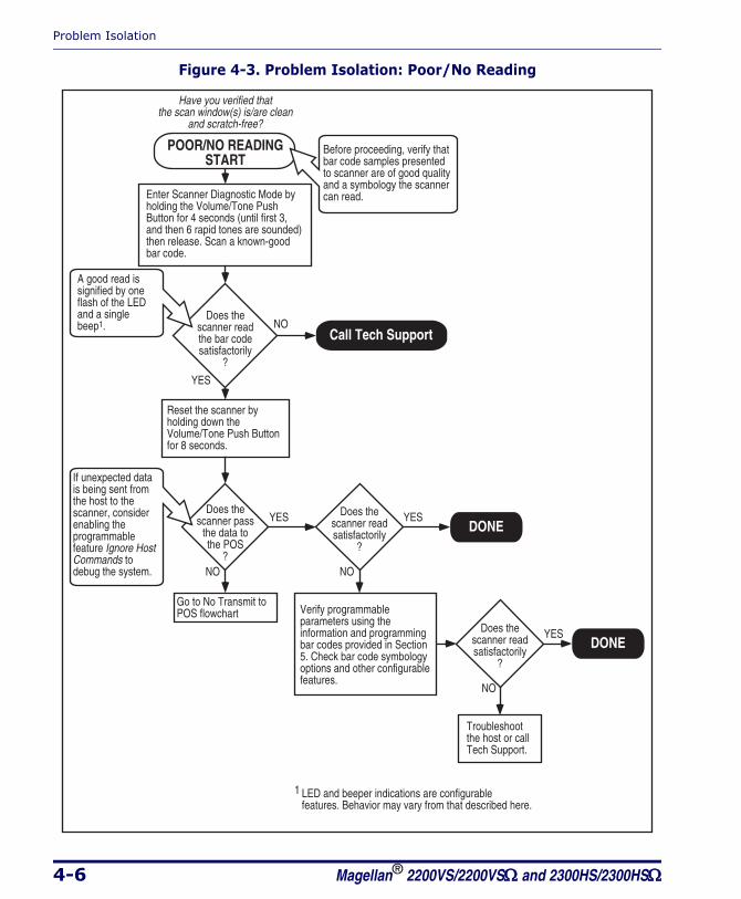
Figure 4-3. Problem Isolation: Poor/No Reading
DONE
DONE
POOR/NO READINGSTART
Have you verified thatthe scan window(s) is/are clean
and scratch-free?
YES
NODoes the
scanner readthe bar codesatisfactorily
?
Verify programmable parameters using the information and programming bar codes provided in Section 5. Check bar code symbology options and other configurable features.
Reset the scanner by holding down the Volume/Tone Push Button for 8 seconds.
Troubleshoot the host or call Tech Support.
YES
NO
Does thescanner pass
the data tothe POS
?
YES
NO
Does thescanner readsatisfactorily
?
YES
NO
Does thescanner readsatisfactorily
?
Enter Scanner Diagnostic Mode by holding the Volume/Tone Push Button for 4 seconds (until first 3, and then 6 rapid tones are sounded) then release. Scan a known-good bar code.
A good read is signified by one flash of the LED and a single beep1.
If unexpected data is being sent from the host to the scanner, consider enabling the programmable feature Ignore HostCommands to debug the system.
Before proceeding, verify that bar code samples presented to scanner are of good quality and a symbology the scanner can read.
LED and beeper indications are configurable features. Behavior may vary from that described here.1
Call Tech Support
Go to No Transmit toPOS flowchart
Flowcharts
Product Reference Guide 4-7
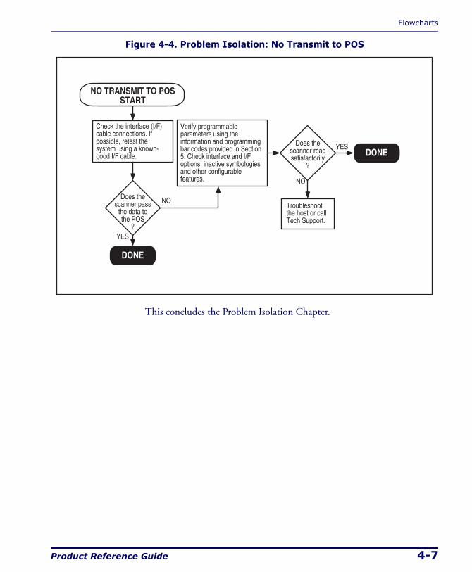
Figure 4-4. Problem Isolation: No Transmit to POS
This concludes the Problem Isolation Chapter.
DONE
DONE
NO TRANSMIT TO POSSTART
Verify programmable parameters using the information and programming bar codes provided in Section 5. Check interface and I/F options, inactive symbologies and other configurable features.
Troubleshoot the host or call Tech Support.
YES
NO
Does thescanner readsatisfactorily
?
Check the interface (I/F) cable connections. If possible, retest the system using a known-good I/F cable.
YES
NODoes thescanner pass
the data tothe POS
?

Problem Isolation
4-8 Magellan® 2200VS/2200VSΩ and 2300HS/2300HSΩ
NOTES
Product Reference Guide 5-1
Chapter 5
Programming
Introduction to Label ProgrammingThe programming bar code labels contained in this manual will allow you to customize and configure features and settings for your scanner. To ensure full compatibility and proper function, use only the programming bar codes in this manual and other product-specific publications to pro-gram scanner features.
This manual has been developed to make it quick and easy for users of all levels to find the information needed to understand and configure fea-tures. The following descriptions will help you to determine where to go from here.
Understanding the BasicsIf you have little or no prior experience with programming using bar code labels, you should review the first few pages of this section to familiarize yourself with the basics of scanner programming before performing any changes to your configuration.
Integrating the Scanner With Your Host SystemYour scanner MUST be equipped with the correct hardware (interface board, cable, etc.) to properly communicate with your host system. Con-tact your dealer for information if you have questions about your scanner’s hardware compatibility.
Programming
5-2 Magellan® 2200VS/2200VSΩ and 2300HS/2300HSΩ
You may also want to contact the dealer or your system administrator if you have no record of how your scanner was pre-programmed at the fac-tory. Scanners are typically programmed with the default settings for spe-cific interface types (see Appendix E, Factory Defaults for more information); however, your scanner may have been custom configured with settings that are unique to your company or application.
Once you know the scanner’s current settings, you can determine what changes will be required to allow communication with your host system and/or optional features you choose to modify to customize your installa-tion. After recording the modifications needed, finish reading this section, then turn to the appropriate page and follow the instructions to program the scanner.
When all scanner features are programmed to your satisfaction, the scan-ner is ready to be placed into operation.
Customizing Your Scanner’s OperationMost scanner programming falls within three general categories:
• General Scanner Features - are features common to all interface types. Examples include beeper adjustments such as volume and length, read verification settings, etc.
• Interface Related Features - are the mandatory settings necessary to allow communication with your host terminal. Examples of these settings are: RS-232 baud rate and parity.
CAUTION
It is possible, via programming bar codes, to change the interface type (for example: from RS-232 to IBM Port 17). Great care should be taken to select the correct interface type, since you can cause dam-age to the scanner and/or POS terminal by attempting to change to an incompatible interface. ALWAYS make interface selections with the host cable DISCONNECTED.
NOTE
Ensure that your planned modifications are compatible with the cur-rent interface. For example, baud rate selections are only valid in the RS-232 interface. The scanner will sound an error tone when scan-ning programming labels for features invalid to the current interface group.
Programming Overview
Product Reference Guide 5-3
• Symbology Programming - gives the scanner the capability to auto-discriminate as few as one, and as many as all available symbologies. For optimal scanner performance enable only those symbologies required. Additionally the scanner may be programmed with the standard options available for the various symbologies, such as check digit, minimum label length, fixed and variable length bar codes, etc.
If you experience difficulties, have questions or require additional infor-mation, contact your local distributor, or call your dealer or sales represen-tative.
Programming OverviewThe scanner’s programmable feature settings can be modified to accom-modate your system’s unique requirements. These settings can be commu-nicated to the scanner in one of two ways:
1. Commands can be sent directly from the host. A limited set of host commands are available. Refer to Appendix D for more details or contact Tech Support.
2. Programming bar code labels can also be used to modify the scan-ner’s programmable settings. This manual provides the bar code labels and instructions necessary to configure the scanner’s features and options.
NOTE
When you program the scanner using any of the methods above, the scanner will store the changes until reprogrammed or returned to fac-tory defaults.
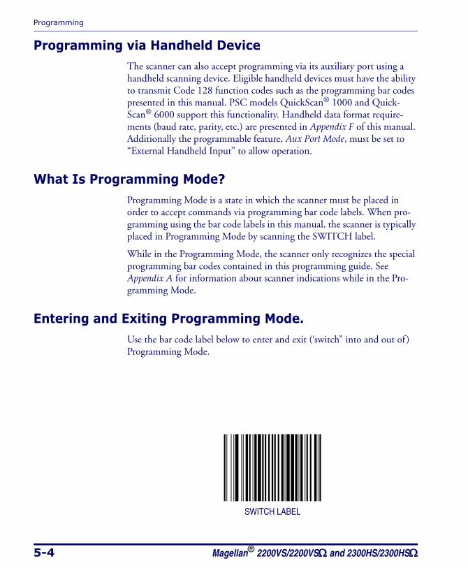
Programming
5-4 Magellan® 2200VS/2200VSΩ and 2300HS/2300HSΩ
Programming via Handheld DeviceThe scanner can also accept programming via its auxiliary port using a handheld scanning device. Eligible handheld devices must have the ability to transmit Code 128 function codes such as the programming bar codes presented in this manual. PSC models QuickScan® 1000 and Quick-Scan® 6000 support this functionality. Handheld data format require-ments (baud rate, parity, etc.) are presented in Appendix F of this manual. Additionally the programmable feature, Aux Port Mode, must be set to “External Handheld Input” to allow operation.
What Is Programming Mode?Programming Mode is a state in which the scanner must be placed in order to accept commands via programming bar code labels. When pro-gramming using the bar code labels in this manual, the scanner is typically placed in Programming Mode by scanning the SWITCH label.
While in the Programming Mode, the scanner only recognizes the special programming bar codes contained in this programming guide. See Appendix A for information about scanner indications while in the Pro-gramming Mode.
Entering and Exiting Programming Mode.Use the bar code label below to enter and exit (‘switch” into and out of ) Programming Mode.
SWITCH LABEL
Programming Overview
Product Reference Guide 5-5
Programming SessionA typical programming session is conducted as follows:
1. Scan the SWITCH bar code to place the scanner in Programming Mode. Depending upon its current programming, the scanner may emit a beep or beeps, indicating it has read the bar code and the green LED will flash on and off slowly while the scanner remains in Programming Mode. Normal scanning functions are disabled.
2. Scan the programming bar code(s) that is (are) specially encoded to
make the desired changes. With few exceptions1, the scanner will emit a triple beep each time you scan a valid programming bar code.
Additionally, when programming a feature requiring you to scan single digits to set a multi-digit number, such as Minimum Label Length, scan-ning the SWITCH bar code (or any item tag/item value bar code) before completing all input will result in an error tone and cause the scanner to exit Programming Mode. Under these circumstances, the current feature you were trying to set is thrown out; any previous bar codes scanned dur-ing the session will take effect.
1. Some features, such as Minimum Label Length, require you to select the label’s length by scan-ning a series of single-digit bar codes. A single ‘good read’ beep is sounded when scanning these single digits in Programming Mode. Only the final required digit in the sequence will produce a tri-ple beep when scanned, indicating a successfully programmed feature.
NOTE
Not all features are available for all interfaces and the scanner will sound an error tone when scanning programming bar codes for fea-tures invalid to the current interface. Only features supported by the currently active interface will be implemented.
NOTE
If a bar code is scanned that changes the scanner’s interface, all previ-ous configuration items scanned in the programming session are lost.
Programming
5-6 Magellan® 2200VS/2200VSΩ and 2300HS/2300HSΩ
3. Scan the SWITCH bar code to save any new settings and exit Pro-gramming Mode. The scanner will sound a beep and reset upon exiting Programming Mode, and the green LED will return to its usual state (on steady or off ). The scanner will exit Programming Mode under the following con-ditions:
— the programming sequence has been completed or the SWITCH bar code is scanned
— five minutes have passed without scanning activity. Any data
programmed during the current session will be ignored1, and the scanner will reset and revert to its condition previous to initiating the exited session.
— power is disconnected. Disconnecting power during Pro-gramming Mode, before scanning the SWITCH bar code, will cause all new settings to be ignored. On power-up, the scanner will return to previous settings.
4. Maintain a good record of all changes made to ensure that you know if the original factory settings have been changed.
NOTE
It is recommended that programming sessions be limited to one feature at a time. Should you make a mistake in the programming sequence, it can be difficult to discover where an error has been made if several features are programmed at once. Additionally, it can be confusing to determine which features may or may not have been successfully set following such a session.
1. Exception: If an interface bar code had been read while in Programming Mode, the scanner will operate on the default settings for the new interface.
Programming Overview
Product Reference Guide 5-7
Programming Sequence
To modify a scanner feature (item), the programming bar codes contained in this manual must be scanned in a given sequence depending upon the feature being programmed (as shown in Table 5-1). There are three possi-ble programming sequences:
A. Programming sample A (the most commonly used format) demon-strates how three bar codes are scanned in sequence to do the follow-ing:
1. Place the scanner in Programming Mode (SWITCH bar code).
2. Scan the Item Tag1 that will enable the new feature.
3. End the programming session and reset the scanner (SWITCH bar code).
B. Sample B provides an example of a programming feature requiring the entry of a range value. Like sample A, the scanner is placed in Programming Mode and an Item Tag1 is scanned. Then, a value must be entered before ending the programming session. In the example, three digits must be scanned from the number pad in Appendix C. This type of format, requiring several bar codes, is nec-essary to allow flexible programming for item values with larger numeric ranges.
C. The programming sequence shown in example C requires scanning of a single, extended length bar code. This special programming bar code contains all the data necessary to enter Programming Mode, set the Item Tag1 and Item Value, and exit Programming Mode (all in one step).
NOTE
If the scanner’s interface type must be changed, always be sure that interface configuration is the FIRST item scanned during a program-ming session. (Changing an interface type resets ALL other configura-tion items to the factory default for that interface type.)
1. An “Item Tag” is a term used to describe an assigned number, which is encoded in a programming bar code, that toggles (selects, enables, disables, etc.) a specific programming feature.
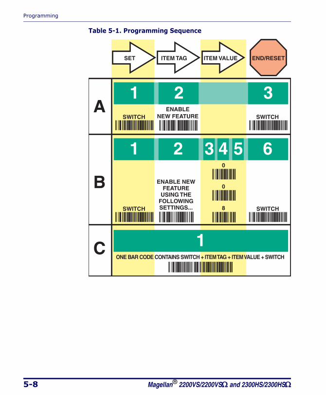
Programming
5-8 Magellan® 2200VS/2200VSΩ and 2300HS/2300HSΩ
Table 5-1. Programming Sequence
1
1
C
A
B
2 3
1 2 3 4 5 6
SET
SWITCHENABLE
NEW FEATURE
ENABLE NEWFEATURE
USING THEFOLLOWINGSETTINGS...
SWITCH
SWITCH SWITCH
0
8
ITEM TAG ITEM VALUE END/RESET
0
ONE BAR CODE CONTAINS SWITCH + ITEM TAG + ITEM VALUE + SWITCH
LED and Beeper Indicators
Product Reference Guide 5-9
LED and Beeper IndicatorsThe scanner provides a set of indicators that verify/announce the various scanner functions.
If You Make a Mistake...If, during a programming session, you find that you are unsure of the scanner’s settings or wish to reset the scanner’s configuration, use the Return to Factory Settings label below to return the scanner’s configura-tion to the factory settings. Scanning this label will also reset any changes made during previous programming sessions.
Return to Factory SettingsScan this bar code to return the scanner to the default settings configured at the factory. This bar code is typically used to return the scanner to a “known” operating state when the present programming status is not known, faulty, or suspect.
The process of Returning to Factory Settings requires two steps:
1. Scan the Return to Factory Settings bar code.
2. Set your required interface type using the instructions in Interface Related Features on page 5-37.
Step 2 is important because the Return to Factory Setting bar code may alos change your scanner’s interface type.
CAUTION
Use this bar code with caution, since it will reset ALL features that may have been programmed since the scanner’s installation.
NOTE
DO NOT scan the SWITCH bar code before and after scanning this bar code.

Programming
5-10 Magellan® 2200VS/2200VSΩ and 2300HS/2300HSΩ
RETURN TO FACTORY SETTINGS
Test ModeUse this feature to place the scanner into a testing, or “demo” mode. This special mode disables the scanner interface, meaning that bar code data is not sent out to the host via the scanner interface. This allows the bar code to be scanned continuously without requiring a response from the POS terminal.
To return the scanner to normal function, scan the TEST MODE = DIS-ABLE bar code below.
TEST MODE = DISABLE
TEST MODE = ENABLE
NOTE
DO NOT scan the SWITCH bar code before and after scanning the bar codes on this page.
Scanning the TEST MODE = DISABLE bar code sets the Double Read Timeout to 600ms.
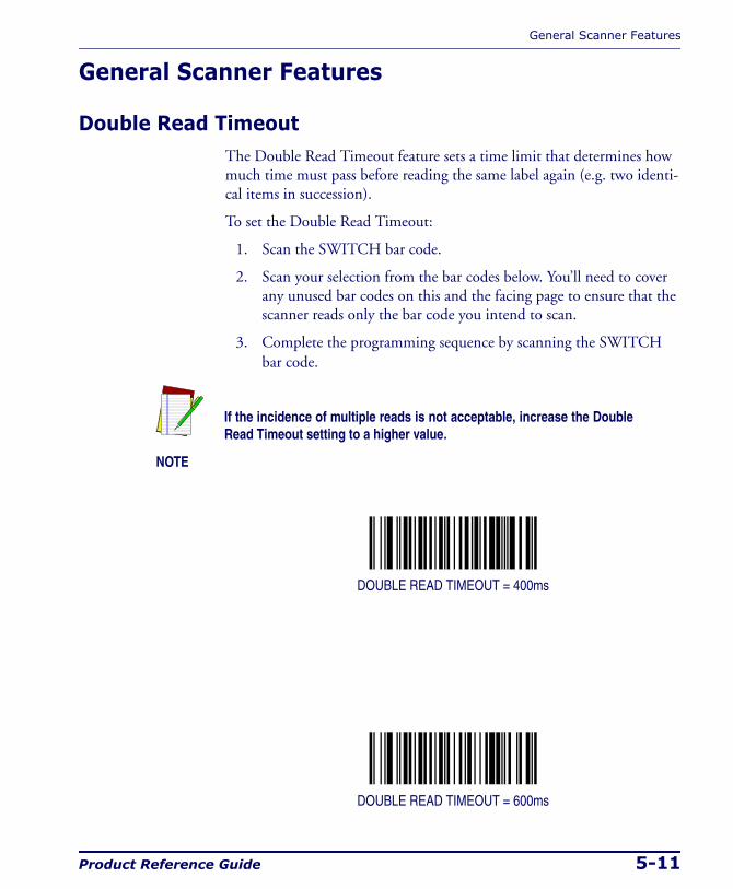
General Scanner Features
Product Reference Guide 5-11
General Scanner Features
Double Read TimeoutThe Double Read Timeout feature sets a time limit that determines how much time must pass before reading the same label again (e.g. two identi-cal items in succession).
To set the Double Read Timeout:
1. Scan the SWITCH bar code.
2. Scan your selection from the bar codes below. You’ll need to cover any unused bar codes on this and the facing page to ensure that the scanner reads only the bar code you intend to scan.
3. Complete the programming sequence by scanning the SWITCH bar code.
DOUBLE READ TIMEOUT = 400ms
DOUBLE READ TIMEOUT = 600ms
NOTE
If the incidence of multiple reads is not acceptable, increase the Double Read Timeout setting to a higher value.

Programming
5-12 Magellan® 2200VS/2200VSΩ and 2300HS/2300HSΩ
Double Read Timeout — continuedRemember to cover any unused bar codes on this and the facing page to ensure that the scanner reads only the bar code you intend to scan.
DOUBLE READ TIMEOUT = 800ms
DOUBLE READ TIMEOUT = 1 SECOND
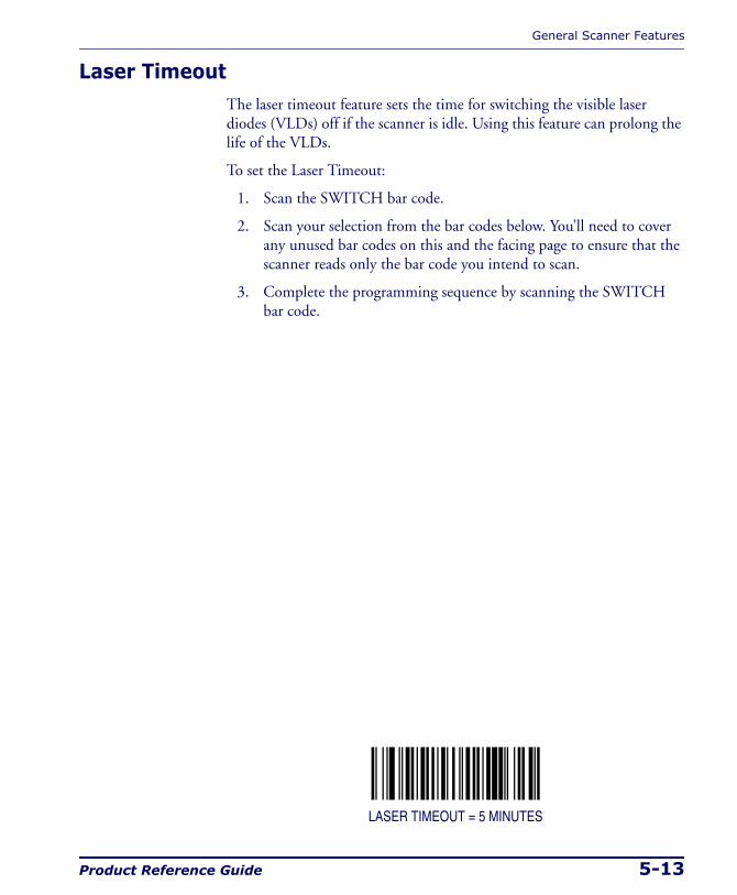
General Scanner Features
Product Reference Guide 5-13
Laser TimeoutThe laser timeout feature sets the time for switching the visible laser diodes (VLDs) off if the scanner is idle. Using this feature can prolong the life of the VLDs.
To set the Laser Timeout:
1. Scan the SWITCH bar code.
2. Scan your selection from the bar codes below. You’ll need to cover any unused bar codes on this and the facing page to ensure that the scanner reads only the bar code you intend to scan.
3. Complete the programming sequence by scanning the SWITCH bar code.
LASER TIMEOUT = 5 MINUTES

Programming
5-14 Magellan® 2200VS/2200VSΩ and 2300HS/2300HSΩ
Laser Timeout — continuedRemember to cover any unused bar codes on this and the facing page to ensure that the scanner reads only the bar code you intend to scan.
LASER TIMEOUT = 10 MINUTES
LASER TIMEOUT = 15 MINUTES

General Scanner Features
Product Reference Guide 5-15
Motor TimeoutThe Motor Timeout feature sets the time for automatically switching the motor off when the scanner is not in use.
To set the Motor Timeout:
1. Scan the SWITCH bar code.
2. Scan your selection from the bar codes below. You’ll need to cover any unused bar codes on this and the facing page to ensure that the scanner reads only the bar code you intend to scan.
3. Complete the programming sequence by scanning the SWITCH bar code.
MOTOR TIMEOUT = 5 MINUTES
NOTE
Laser safety requires that the laser switch off before the motor. If you set the motor timeout shorter than the laser timeout, the motor and the laser will both shut off when the motor timeout expires.
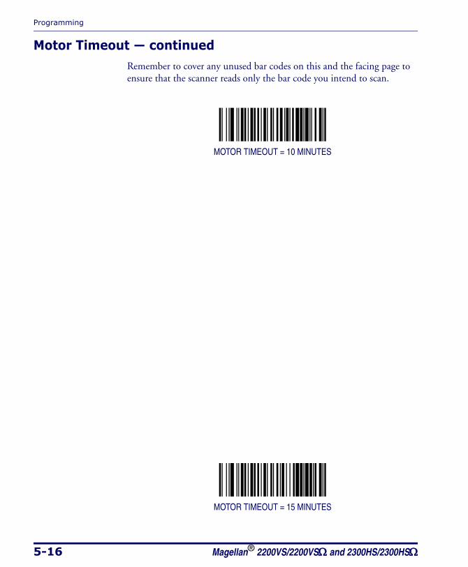
Programming
5-16 Magellan® 2200VS/2200VSΩ and 2300HS/2300HSΩ
Motor Timeout — continuedRemember to cover any unused bar codes on this and the facing page to ensure that the scanner reads only the bar code you intend to scan.
MOTOR TIMEOUT = 10 MINUTES
MOTOR TIMEOUT = 15 MINUTES
General Scanner Features
Product Reference Guide 5-17
Motor Timeout — continuedRemember to cover any unused bar codes on this and the facing page to ensure that the scanner reads only the bar code you intend to scan.
MOTOR TIMEOUT = 30 MINUTES
MOTOR TIMEOUT = 60 MINUTES

Programming
5-18 Magellan® 2200VS/2200VSΩ and 2300HS/2300HSΩ
Green LED Idle StateThis feature specifies the state of the green scanner LED when the scanner is idle and ready to read a label. Options are:
• Off
• On dim
To set the LED Idle State:
1. Scan the SWITCH bar code.
2. Scan your selection from the bar codes below. You’ll need to cover any unused bar codes on this and the facing page to ensure that the scanner reads only the bar code you intend to scan.
3. Complete the programming sequence by scanning the SWITCH bar code.
GREEN LED IDLE STATE = OFF
GREEN LED IDLE STATE = ON DIM
General Scanner Features
Product Reference Guide 5-19
Scanner Button OptionsConfigure the scanner volume button to one of the following modes of operation:
• Enable all functions: Volume, tone, diagnostics and reset.
• Enable only volume, tone and reset.
• Enable reset only.
• Disable all button functions
To set the desired Scanner Button Option:
1. Scan the SWITCH bar code.
2. Scan your selection from the bar codes below. You’ll need to cover any unused bar codes on this and the facing page to ensure that the scanner reads only the bar code you intend to scan.
3. Complete the programming sequence by scanning the SWITCH bar code.
SCANNER BUTTON OPTION = ENABLE ALL FUNCTIONS
SCANNER BUTTON OPTION = ENABLE ONLY VOLUME/TONE/RESET

Programming
5-20 Magellan® 2200VS/2200VSΩ and 2300HS/2300HSΩ
Scanner Button Options — continuedRemember to cover any unused bar codes on this and the facing page to ensure that the scanner reads only the bar code you intend to scan.
SCANNER BUTTON OPTION = ENABLE RESET ONLY
SCANNER BUTTON OPTION = DISABLE ALL BUTTON FUNCTIONS
General Scanner Features
Product Reference Guide 5-21
Power-up Beep ControlSpecifies the type of audible indication that is made when entering scan-ner-active mode on power-up. Choices are:
• No beep
• One beep
• Three beeps
To set the Power-up Beep:
1. Scan the SWITCH bar code.
2. Scan your selection from the three bar codes below. You’ll need to cover any unused bar codes on this and the facing page to ensure that the scanner reads only the bar code you intend to scan.
3. Complete the programming sequence by scanning the SWITCH bar code.
POWER-UP BEEP = OFF

Programming
5-22 Magellan® 2200VS/2200VSΩ and 2300HS/2300HSΩ
Power-up Beep Control — continuedRemember to cover any unused bar codes on this and the facing page to ensure that the scanner reads only the bar code you intend to scan.
POWER-UP BEEP = ONE BEEP
POWER-UP BEEP = THREE BEEPS
General Scanner Features
Product Reference Guide 5-23
Good Read Beep ControlThis feature enables/disables scanner beep upon successfully decoding of a label.
To set this feature:
1. Scan the SWITCH bar code.
2. Scan your selection from the two bar codes below. You’ll need to cover any unused bar codes on this and the facing page to ensure that the scanner reads only the bar code you intend to scan.
3. Complete the programming sequence by scanning the SWITCH bar code.
GOOD READ BEEP = DISABLE
GOOD READ BEEP = ENABLE
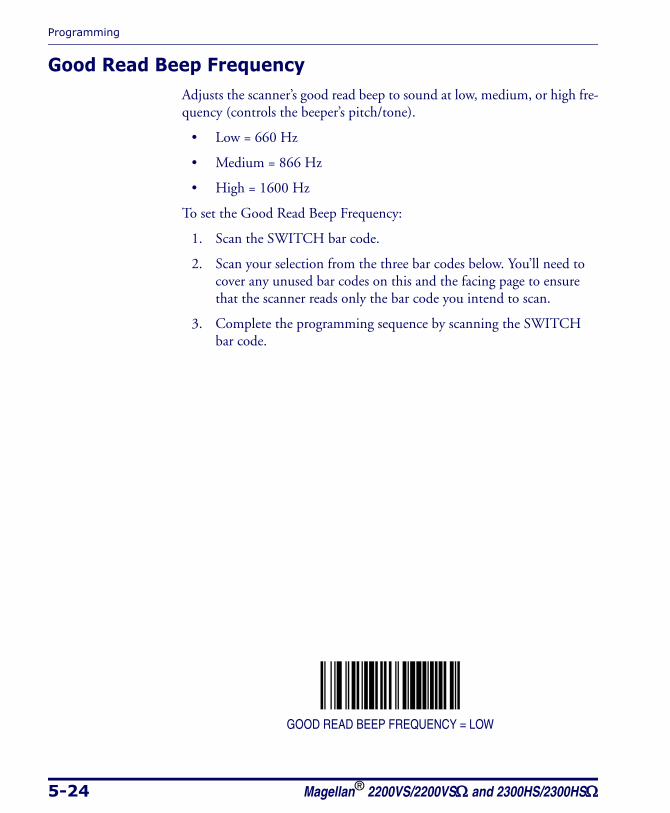
Programming
5-24 Magellan® 2200VS/2200VSΩ and 2300HS/2300HSΩ
Good Read Beep FrequencyAdjusts the scanner’s good read beep to sound at low, medium, or high fre-quency (controls the beeper’s pitch/tone).
• Low = 660 Hz
• Medium = 866 Hz
• High = 1600 Hz
To set the Good Read Beep Frequency:
1. Scan the SWITCH bar code.
2. Scan your selection from the three bar codes below. You’ll need to cover any unused bar codes on this and the facing page to ensure that the scanner reads only the bar code you intend to scan.
3. Complete the programming sequence by scanning the SWITCH bar code.
GOOD READ BEEP FREQUENCY = LOW
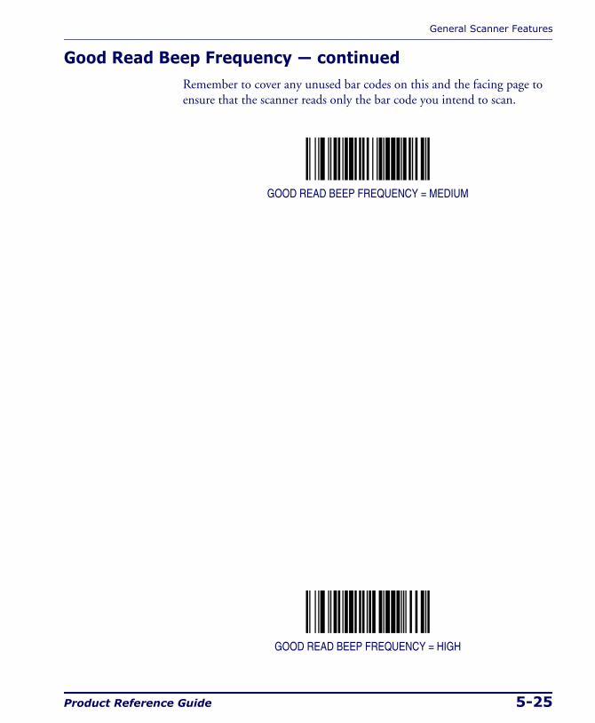
General Scanner Features
Product Reference Guide 5-25
Good Read Beep Frequency — continuedRemember to cover any unused bar codes on this and the facing page to ensure that the scanner reads only the bar code you intend to scan.
GOOD READ BEEP FREQUENCY = MEDIUM
GOOD READ BEEP FREQUENCY = HIGH
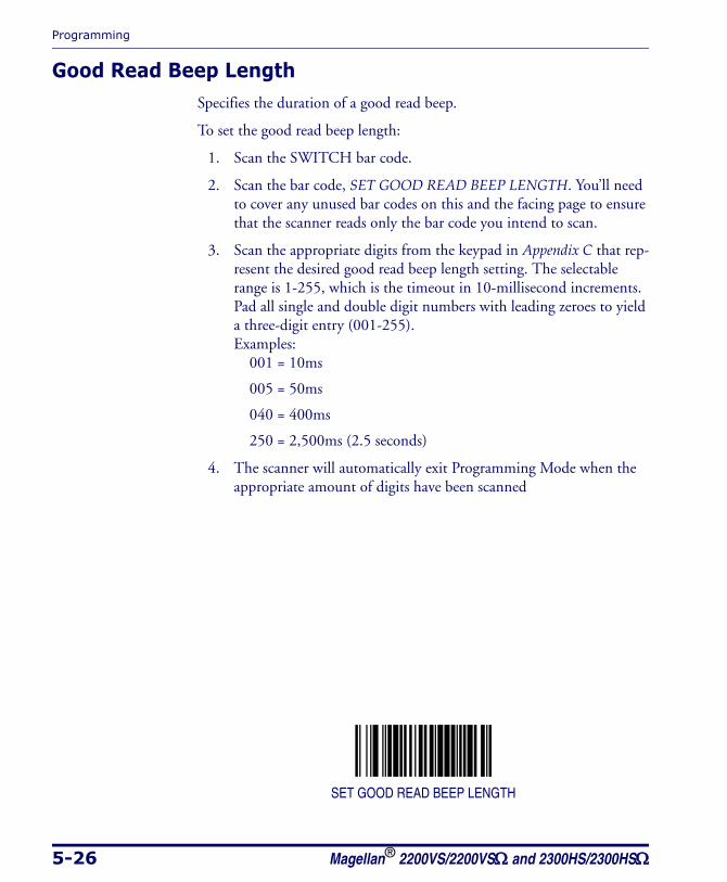
Programming
5-26 Magellan® 2200VS/2200VSΩ and 2300HS/2300HSΩ
Good Read Beep LengthSpecifies the duration of a good read beep.
To set the good read beep length:
1. Scan the SWITCH bar code.
2. Scan the bar code, SET GOOD READ BEEP LENGTH. You’ll need to cover any unused bar codes on this and the facing page to ensure that the scanner reads only the bar code you intend to scan.
3. Scan the appropriate digits from the keypad in Appendix C that rep-resent the desired good read beep length setting. The selectable range is 1-255, which is the timeout in 10-millisecond increments. Pad all single and double digit numbers with leading zeroes to yield a three-digit entry (001-255). Examples:
001 = 10ms
005 = 50ms
040 = 400ms
250 = 2,500ms (2.5 seconds)
4. The scanner will automatically exit Programming Mode when the appropriate amount of digits have been scanned
SET GOOD READ BEEP LENGTH
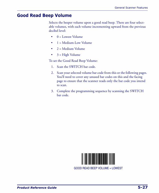
General Scanner Features
Product Reference Guide 5-27
Good Read Beep VolumeSelects the beeper volume upon a good read beep. There are four select-able volumes, with each volume incrementing upward from the previous decibel level:
• 0 = Lowest Volume
• 1 = Medium-Low Volume
• 2 = Medium Volume
• 3 = High Volume
To set the Good Read Beep Volume:
1. Scan the SWITCH bar code.
2. Scan your selected volume bar code from this or the following pages. You’ll need to cover any unused bar codes on this and the facing page to ensure that the scanner reads only the bar code you intend to scan.
3. Complete the programming sequence by scanning the SWITCH bar code.
GOOD READ BEEP VOLUME = LOWEST

Programming
5-28 Magellan® 2200VS/2200VSΩ and 2300HS/2300HSΩ
Good Read Beep Volume — continuedRemember to cover any unused bar codes on this and the facing page to ensure that the scanner reads only the bar code you intend to scan.
GOOD READ BEEP VOLUME = MEDIUM LOW
GOOD READ BEEP VOLUME = MEDIUM
General Scanner Features
Product Reference Guide 5-29
Good Read Beep Volume — continuedRemember to cover any unused bar codes on this and the facing page to ensure that the scanner reads only the bar code you intend to scan.
GOOD READ BEEP VOLUME = HIGH
Programming
5-30 Magellan® 2200VS/2200VSΩ and 2300HS/2300HSΩ
Good Read When to IndicateThis feature specifies when the scanner will provide indication (beep and/or flash its green LED) upon successfully reading a bar code.
• Good Read = Indicate after decode
• Good Read = Indicate after transmit
• Good Read = Indicate after CTS goes inactive, then active
To set the Good Read When to Indicate feature:
1. Scan the SWITCH bar code.
2. Scan the desired mode bar code from this page. You’ll need to cover any unused bar codes on this and the facing page to ensure that the scanner reads only the bar code you intend to scan.
3. Complete the programming sequence by scanning the SWITCH bar code.
GOOD READ = INDICATE AFTER DECODE
NOTE
The “Indicate after CTS goes inactive...” mode applies to RS-232 STD and RS-232 WN interfaces only. If set to this mode in other interfaces, “Indi-cate after decode” mode will be implemented.
General Scanner Features
Product Reference Guide 5-31
Good Read When to Indicate — continuedRemember to cover any unused bar codes on this and the facing page to ensure that the scanner reads only the bar code you intend to scan.
GOOD READ = INDICATE AFTER TRANSMIT
GOOD READ = INDICATE AFTER CTS GOES INACTIVE, THEN ACTIVE(RS-232 ONLY)
Programming
5-32 Magellan® 2200VS/2200VSΩ and 2300HS/2300HSΩ
EAS Active StateSpecifies the active state polarity of EAS (Electronic Article Surveillance); the inactive state is its opposite polarity. EAS output goes active during the good read of a bar code, allowing the EAS device to deactivate a tag on the product.
To set the EAS Active State:
1. Scan the SWITCH bar code.
2. Scan bar code below representing the desired setting. You’ll need to cover any unused bar codes on this and the facing page to ensure that the scanner reads only the bar code you intend to scan.
3. Complete the programming sequence by scanning the SWITCH bar code.
EAS ACTIVE STATE = ACTIVE LOW
EAS ACTIVE STATE = ACTIVE HIGH
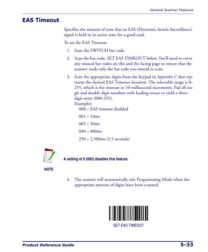
General Scanner Features
Product Reference Guide 5-33
EAS TimeoutSpecifies the amount of time that an EAS (Electronic Article Surveillance) signal is held in its active state for a good read.
To set the EAS Timeout:
1. Scan the SWITCH bar code.
2. Scan the bar code, SET EAS TIMEOUT below. You’ll need to cover any unused bar codes on this and the facing page to ensure that the scanner reads only the bar code you intend to scan.
3. Scan the appropriate digits from the keypad in Appendix C that rep-resent the desired EAS Timeout duration. The selectable range is 0-255, which is the timeout in 10-millisecond increments. Pad all sin-gle and double digit numbers with leading zeroes to yield a three-digit entry (000-255). Examples:
000 = EAS timeout disabled
001 = 10ms
005 = 50ms
040 = 400ms
250 = 2,500ms (2.5 seconds)
4. The scanner will automatically exit Programming Mode when the appropriate amount of digits have been scanned
SET EAS TIMEOUT
NOTE
A setting of 0 (000) disables this feature.

Programming
5-34 Magellan® 2200VS/2200VSΩ and 2300HS/2300HSΩ
Aux Port ModeSelects the usage for the scanner’s optional auxilliary port. The choices listed below are mutually exclusive (only one option can be active at a time).
• Disabled — Port is inactive
• External Handheld Input — Supports PSC® handheld scanners (QuickScan 1000, QuickScan 6000, PowerScan) as well as other models such as the Symbol® HotShot. Call your dealer for more information about supported devices.
• PIR — (Productivity Index Reporting) allows the scanner to provide information to an external computer indicating how easy the label was to read.
To set this feature:
1. Scan the SWITCH bar code.
2. Scan your selection from the bar codes below. You’ll need to cover any unused bar codes on this and the facing page to ensure that the scanner reads only the bar code you intend to scan.
3. Complete the programming sequence by scanning the SWITCH bar code.
AUX PORT MODE = DISABLE
NOTE
Cable pinout information for the Aux Port is provided in Appendix B of this manual. A connected handheld scanner must be configured to trans-mit data as outlined in Appendix F.
General Scanner Features
Product Reference Guide 5-35
Aux Port Mode — continuedRemember to cover any unused bar codes on this and the facing page to ensure that the scanner reads only the bar code you intend to scan.
AUX PORT MODE = EXTERNAL HANDHELD INPUT
AUX PORT MODE = PIR
Programming
5-36 Magellan® 2200VS/2200VSΩ and 2300HS/2300HSΩ
Productivity Index Reporting (PIR)When PIR is enabled, label quality data is appended to decoded data before being presented to the POS. The PIR feature allows the scanner to provide information to an external computer indicating how easy the label was to read.
To set this feature:
1. Scan the SWITCH bar code.
2. Scan your selection from the bar codes below. You’ll need to cover any unused bar codes on this and the facing page to ensure that the scanner reads only the bar code you intend to scan.
3. Complete the programming sequence by scanning the SWITCH bar code.
PIR = DISABLE
PIR = ENABLE
NOTE
This value-added feature is a factory-programmed option. Contact your dealer for information about upgrading your system to include this advanced capability.
Interface Related Features
Product Reference Guide 5-37
Interface Related Features
Interface TypeSpecifies the current scanner interface. Selections are:
INTERFACE TYPE PAGE NUMBER
RS-232 Standard 5-39
RS-232 Wincor-Nixdorf 5-40
RS-232 Single Cable 5-41
IBM USB 5-43
IBM Port 17 5-42
USB Keyboard 5-44
PC Keyboard Wedge 5-45
NOT USER-SELECTABLE
Null InterfaceCommon factory configuration for
new scanners
NOTE
A new scanner may have been shipped from the factory with a Null Interface (no interface type selected) to ensure system compatibility at installation. In this case, the correct Interface Type programming bar code must be scanned first before the scanner can be used with a POS system.
NOTE
If the scanner’s interface type must be changed, always be sure that interface configuration is the FIRST item scanned during a program-ming session. (Changing an interface type resets ALL other configura-tion items to the factory default for that interface type.)
Programming
5-38 Magellan® 2200VS/2200VSΩ and 2300HS/2300HSΩ
Interface Type — continuedTo select the desired interface:
1. Disconnect current interface cable(s) if currently connected.
2. Scan the SWITCH bar code
3. Scan the bar code representing the appropriate interface located on the following pages. You’ll need to cover any unused bar codes adja-cent to and on any facing pages to ensure the scanner reads only the bar code you intend to scan.
4. Complete the programming sequence by scanning the SWITCH bar code.
5. Connect new interface cable(s).
CAUTION
Great care should be taken to select the correct interface type, since you can cause damage to the scanner and/or POS terminal by attempting to change to an incompatible interface. ALWAYS make interface selections with the host cable DISCONNECTED.
NOTE
When an interface is selected, the scanner loads the factory configura-tion for that interface as the selection is made, erasing any and all custom configuration that may have previously been done.
NOTE
Once the correct interface has been set, it will be necessary to proceed to the appropriate pages in this manual that select parameters and options for that interface. For example, if RS-232 is selected, turn to the pages in this manual headed as features specific to the RS-232 interface.
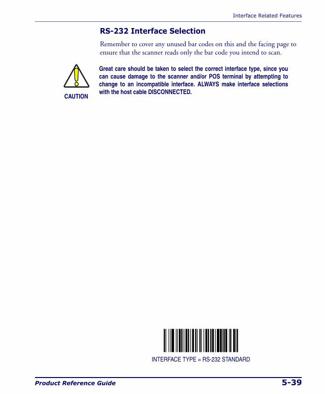
Interface Related Features
Product Reference Guide 5-39
RS-232 Interface Selection
Remember to cover any unused bar codes on this and the facing page to ensure that the scanner reads only the bar code you intend to scan.
INTERFACE TYPE = RS-232 STANDARD
CAUTION
Great care should be taken to select the correct interface type, since you can cause damage to the scanner and/or POS terminal by attempting to change to an incompatible interface. ALWAYS make interface selections with the host cable DISCONNECTED.
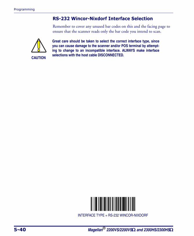
Programming
5-40 Magellan® 2200VS/2200VSΩ and 2300HS/2300HSΩ
RS-232 Wincor-Nixdorf Interface Selection
Remember to cover any unused bar codes on this and the facing page to ensure that the scanner reads only the bar code you intend to scan.
INTERFACE TYPE = RS-232 WINCOR-NIXDORF
CAUTION
Great care should be taken to select the correct interface type, since you can cause damage to the scanner and/or POS terminal by attempt-ing to change to an incompatible interface. ALWAYS make interface selections with the host cable DISCONNECTED.
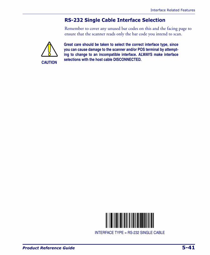
Interface Related Features
Product Reference Guide 5-41
RS-232 Single Cable Interface Selection
Remember to cover any unused bar codes on this and the facing page to ensure that the scanner reads only the bar code you intend to scan.
INTERFACE TYPE = RS-232 SINGLE CABLE
CAUTION
Great care should be taken to select the correct interface type, since you can cause damage to the scanner and/or POS terminal by attempt-ing to change to an incompatible interface. ALWAYS make interface selections with the host cable DISCONNECTED.
Programming
5-42 Magellan® 2200VS/2200VSΩ and 2300HS/2300HSΩ
IBM Port 17 Interface Selection
Remember to cover any unused bar codes on this and the facing page to ensure that the scanner reads only the bar code you intend to scan.
INTERFACE TYPE = IBM PORT 17
CAUTION
Great care should be taken to select the correct interface type, since you can cause damage to the scanner and/or POS terminal by attempting to change to an incompatible interface. ALWAYS make interface selections with the host cable DISCONNECTED.
Interface Related Features
Product Reference Guide 5-43
IBM USB Interface Selection
Remember to cover any unused bar codes on this and the facing page to ensure that the scanner reads only the bar code you intend to scan.
INTERFACE TYPE = IBM USB
CAUTION
Great care should be taken to select the correct interface type, since you can cause damage to the scanner and/or POS terminal by attempting to change to an incompatible interface. ALWAYS make interface selections with the host cable DISCONNECTED.
Programming
5-44 Magellan® 2200VS/2200VSΩ and 2300HS/2300HSΩ
USB Keyboard Interface Selection
Remember to cover any unused bar codes on this and the facing page to ensure that the scanner reads only the bar code you intend to scan.
INTERFACE TYPE = USB KEYBOARD
CAUTION
Great care should be taken to select the correct interface type, since you can cause damage to the scanner and/or POS terminal by attempting to change to an incompatible interface. ALWAYS make interface selections with the host cable DISCONNECTED.
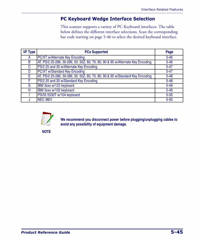
Interface Related Features
Product Reference Guide 5-45
PC Keyboard Wedge Interface Selection
This scanner supports a variety of PC Keyboard interfaces. The table below defines the different interface selections. Scan the corresponding bar code starting on page 5-46 to select the desired keyboard interface.
I/F Type PCs Supported PageA PC/XT w/Alternate Key Encoding 5-46B AT, PS/2 25-286, 30-286, 50, 50Z, 60, 70, 80, 90 & 95 w/Alternate Key Encoding 5-46C PS/2 25 and 30 w/Alternate Key Encoding 5-47D PC/XT w/Standard Key Encoding 5-47E AT, PS/2 25-286, 30-286, 50, 50Z, 60, 70, 80, 90 & 95 w/Standard Key Encoding 5-48F PS/2 25 and 30 w/Standard Key Encoding 5-48G IBM 3xxx w/122 keyboard 5-49H IBM 3xxx w/102 keyboard 5-49I PS/55 5530T w/104 keyboard 5-50J NEC 9801 5-50
NOTE
We recommend you disconnect power before plugging/unplugging cables to avoid any possibility of equipment damage.
Programming
5-46 Magellan® 2200VS/2200VSΩ and 2300HS/2300HSΩ
PC Keyboard Wedge Interface Types
Remember to cover any unused bar codes on this and the facing page to ensure that the scanner reads only the bar code you intend to scan.
INTERFACE TYPE = PC KEYBOARD A
INTERFACE TYPE = PC KEYBOARD B
CAUTION
Great care should be taken to select the correct interface type, since you can cause damage to the scanner and/or POS terminal by attempting to change to an incompatible interface. ALWAYS make interface selections with the host cable DISCONNECTED.
Interface Related Features
Product Reference Guide 5-47
PC Keyboard Wedge Interface Types — continued
Remember to cover any unused bar codes on this and the facing page to ensure that the scanner reads only the bar code you intend to scan.
INTERFACE TYPE = PC KEYBOARD C
INTERFACE TYPE = PC KEYBOARD D
CAUTION
Great care should be taken to select the correct interface type, since you can cause damage to the scanner and/or POS terminal by attempting to change to an incompatible interface. ALWAYS make interface selections with the host cable DISCONNECTED.
Programming
5-48 Magellan® 2200VS/2200VSΩ and 2300HS/2300HSΩ
PC Keyboard Wedge Interface Types — continued
Remember to cover any unused bar codes on this and the facing page to ensure that the scanner reads only the bar code you intend to scan.
INTERFACE TYPE = PC KEYBOARD E
INTERFACE TYPE = PC KEYBOARD F
CAUTION
Great care should be taken to select the correct interface type, since you can cause damage to the scanner and/or POS terminal by attempting to change to an incompatible interface. ALWAYS make interface selections with the host cable DISCONNECTED.
Interface Related Features
Product Reference Guide 5-49
PC Keyboard Wedge Interface Types — continued
Remember to cover any unused bar codes on this and the facing page to ensure that the scanner reads only the bar code you intend to scan.
INTERFACE TYPE = PC KEYBOARD G
INTERFACE TYPE = PC KEYBOARD H
CAUTION
Great care should be taken to select the correct interface type, since you can cause damage to the scanner and/or POS terminal by attempting to change to an incompatible interface. ALWAYS make interface selections with the host cable DISCONNECTED.
Programming
5-50 Magellan® 2200VS/2200VSΩ and 2300HS/2300HSΩ
PC Keyboard Wedge Interface Types — continued
Remember to cover any unused bar codes on this and the facing page to ensure that the scanner reads only the bar code you intend to scan.
INTERFACE TYPE = PC KEYBOARD I
INTERFACE TYPE = PC KEYBOARD J
CAUTION
Great care should be taken to select the correct interface type, since you can cause damage to the scanner and/or POS terminal by attempting to change to an incompatible interface. ALWAYS make interface selections with the host cable DISCONNECTED.
Interface Related Features
Product Reference Guide 5-51
Maximum Host-Transmitted Message LengthSpecifies the maximum number of data characters allowed in messages transmitted to the host.
To set the Maximum Host-Transmitted Message Length:
1. Scan the SWITCH bar code.
2. Scan the bar code, SET MAXIMUM HOST-TRANSMITTED MES-SAGE LENGTH below. You’ll need to cover any unused bar codes on this and the facing page to ensure that the scanner reads only the bar code you intend to scan.
3. Scan the appropriate digits from the keypad in Appendix C that rep-resent the desired maximum host-transmitted message length. The selectable range is 0-249 data characters. (Labels that are longer than this length are not read.) Pad all single and double digit numbers with leading zeroes to yield a three-digit entry (000-249).
4. The scanner will automatically exit Programming Mode when the appropriate amount of digits have been scanned
SET MAXIMUM HOST-TRANSMITTED MESSAGE LENGTH
NOTE
If this configuration item is set to 0 (000), there is no general length limit imposed on data being transmitted to the host.
Programming
5-52 Magellan® 2200VS/2200VSΩ and 2300HS/2300HSΩ
Number of Host Transmission BuffersSpecifies the number of host transmission(s) that may be buffered. By buffering data from a bar code, the scanner can continue to read a new bar code while the old one is being transmitted to the host. Selecting BUFF-ERS = 1 means that the first bar code must be transmitted before a new one can be read. A selection of BUFFERS = 2 means that a new bar code can be read while data from the first bar code is transmitted. When the feature, Good Read Beep Control, is enabled, the scanner will beep when the data is placed in a transmission buffer.
When a DISABLE SCANNER command is received from the host, the scanner will continue to transmit all data that is buffered.
To select the Number of Host Transmission Buffers:
1. Scan the SWITCH bar code.
2. Scan bar code below representing the desired setting. You’ll need to cover any unused bar codes on this and the facing page to ensure that the scanner reads only the bar code you intend to scan.
3. Complete the programming sequence by scanning the SWITCH bar code.
NUMBER OF HOST TRANSMISSION BUFFERS = 1
NUMBER OF HOST TRANSMISSION BUFFERS = 2

Interface Related Features
Product Reference Guide 5-53
Global PrefixThis feature applies to RS-232 interfaces (Standard, Wincor-Nixdorf, and Single Cable). It specifies the prefix that is added to beginning of label transmission.
To specify the Global Prefix Character(s):
1. Scan the SWITCH bar code.
2. Scan the bar code, SET GLOBAL PREFIX below. You’ll need to cover any unused bar codes to ensure the scanner reads only the bar code you intend to scan.
3. Scan the appropriate characters/digits from the keypad in Appendix C that represent the hex designation for the desired character(s). A table containing the ASCII Character Set and their corresponding Hex Values is available in the inside back cover of this manual. ASCII parameters must be input by scanning a pair of hexadecimal digits for each character. Thus, to set a two-character value of AB, bar codes containing the digits ‘4’, ‘1’, ‘4’, and ‘2’ must be scanned. The selectable range for this option is any hex value from 00 to FF. Up to 20 hex pairs can be designated.
4. If designating the full 20 hex pairs, the scanner will automatically exit Programming Mode when the appropriate amount of digits have been scanned. If designating less than 20 hex pairs, you can end the programming sequence early by scanning the TERMINATE SEQUENCE bar code.
5. Complete the programming sequence by scanning the SWITCH bar code.
NOTE
To specify “no Global Prefix,” scan 00.
Programming
5-54 Magellan® 2200VS/2200VSΩ and 2300HS/2300HSΩ
Global Prefix — continuedRemember to cover any unused bar codes on this and the facing page to ensure that the scanner reads only the bar code you intend to scan.
SET GLOBAL PREFIX
TERMINATE SEQUENCE
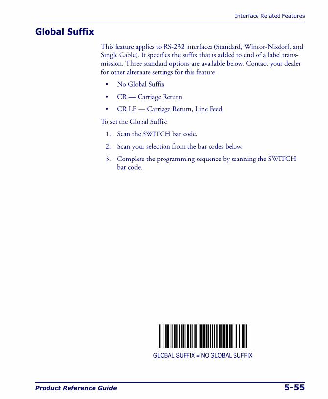
Interface Related Features
Product Reference Guide 5-55
Global SuffixThis feature applies to RS-232 interfaces (Standard, Wincor-Nixdorf, and Single Cable). It specifies the suffix that is added to end of a label trans-mission. Three standard options are available below. Contact your dealer for other alternate settings for this feature.
• No Global Suffix
• CR — Carriage Return
• CR LF — Carriage Return, Line Feed
To set the Global Suffix:
1. Scan the SWITCH bar code.
2. Scan your selection from the bar codes below.
3. Complete the programming sequence by scanning the SWITCH bar code.
GLOBAL SUFFIX = NO GLOBAL SUFFIX
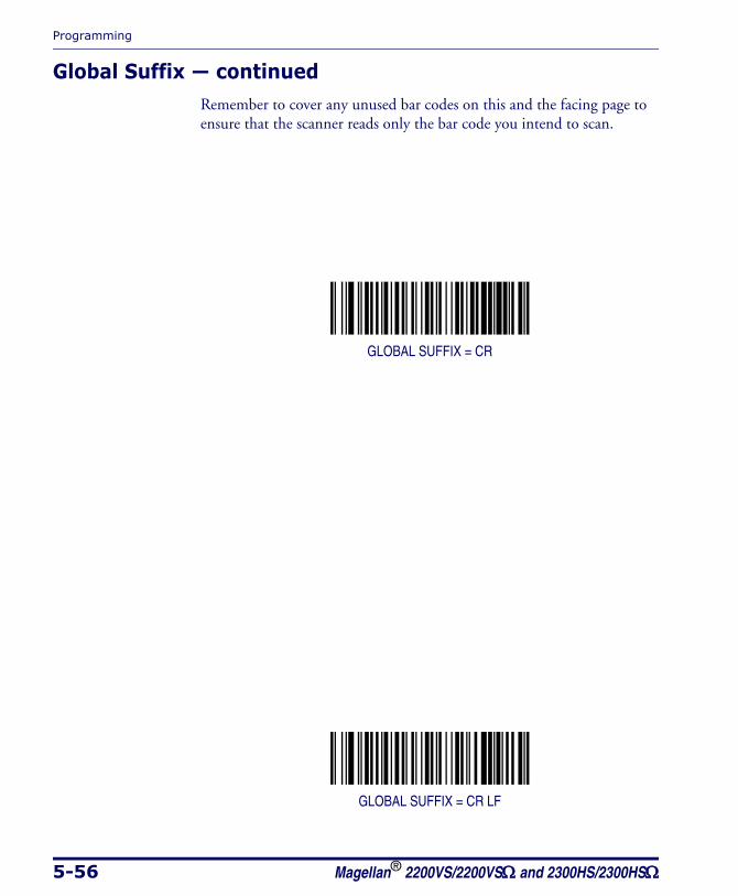
Programming
5-56 Magellan® 2200VS/2200VSΩ and 2300HS/2300HSΩ
Global Suffix — continuedRemember to cover any unused bar codes on this and the facing page to ensure that the scanner reads only the bar code you intend to scan.
GLOBAL SUFFIX = CR
GLOBAL SUFFIX = CR LF
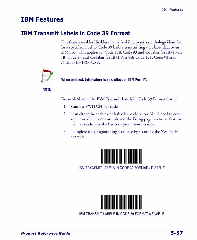
IBM Features
Product Reference Guide 5-57
IBM Features
IBM Transmit Labels in Code 39 FormatThis feature enables/disables scanner's ability to set a symbology identifier for a specified label to Code 39 before transmitting that label data to an IBM host. This applies to: Code 128, Code 93 and Codabar for IBM Port 5B; Code 93 and Codabar for IBM Port 9B; Code 128, Code 93 and Codabar for IBM-USB.
To enable/disable the IBM Transmit Labels in Code 39 Format feature:
1. Scan the SWITCH bar code.
2. Scan either the enable or disable bar code below. You’ll need to cover any unused bar codes on this and the facing page to ensure that the scanner reads only the bar code you intend to scan.
3. Complete the programming sequence by scanning the SWITCH bar code.
IBM TRANSMIT LABELS IN CODE 39 FORMAT = DISABLE
IBM TRANSMIT LABELS IN CODE 39 FORMAT = ENABLE
NOTE
When enabled, this feature has no effect on IBM Port 17.
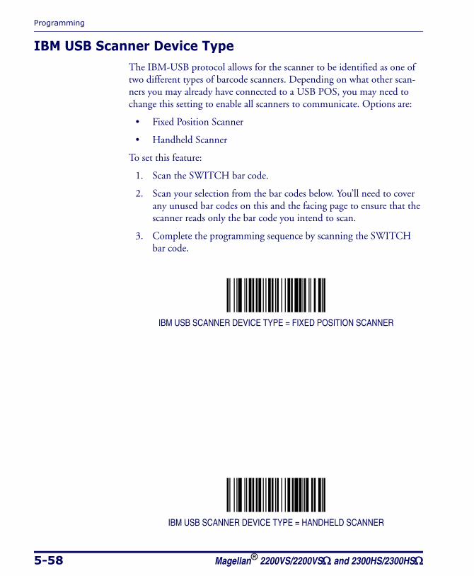
Programming
5-58 Magellan® 2200VS/2200VSΩ and 2300HS/2300HSΩ
IBM USB Scanner Device TypeThe IBM-USB protocol allows for the scanner to be identified as one of two different types of barcode scanners. Depending on what other scan-ners you may already have connected to a USB POS, you may need to change this setting to enable all scanners to communicate. Options are:
• Fixed Position Scanner
• Handheld Scanner
To set this feature:
1. Scan the SWITCH bar code.
2. Scan your selection from the bar codes below. You’ll need to cover any unused bar codes on this and the facing page to ensure that the scanner reads only the bar code you intend to scan.
3. Complete the programming sequence by scanning the SWITCH bar code.
IBM USB SCANNER DEVICE TYPE = FIXED POSITION SCANNER
IBM USB SCANNER DEVICE TYPE = HANDHELD SCANNER
RS-232 Features
Product Reference Guide 5-59
RS-232 Features
RS-232 Baud RateThis feature selects the baud rate required for sending and receiving data.
To specify the RS-232 Baud Rate:
1. Scan the SWITCH bar code.
2. Scan the desired baud rate from the bar codes below and on the immediately following pages. You’ll need to cover any unused bar codes on this and the facing page to ensure that the scanner reads only the bar code you intend to scan.
3. Complete the programming sequence by scanning the SWITCH bar code.
RS-232 BAUD RATE = 1200
RS-232 BAUD RATE = 2400
NOTE
Single cable interfaces are limited to Baud Rate selections up to 19200. They cannot communicate at Baud Rates of 38400 and up.
Programming
5-60 Magellan® 2200VS/2200VSΩ and 2300HS/2300HSΩ
RS-232 Baud Rate — continuedRemember to cover any unused bar codes on this and the facing page to ensure that the scanner reads only the bar code you intend to scan.
RS-232 BAUD RATE = 4800
RS-232 BAUD RATE = 9600

RS-232 Features
Product Reference Guide 5-61
RS-232 Baud Rate — continuedRemember to cover any unused bar codes on this and the facing page to ensure that the scanner reads only the bar code you intend to scan.
RS-232 BAUD RATE = 19200
RS-232 BAUD RATE = 38400

Programming
5-62 Magellan® 2200VS/2200VSΩ and 2300HS/2300HSΩ
RS-232 Baud Rate — continuedRemember to cover any unused bar codes on this and the facing page to ensure that the scanner reads only the bar code you intend to scan.
RS-232 BAUD RATE = 57600
RS-232 BAUD RATE = 115200
RS-232 Features
Product Reference Guide 5-63
RS-232 Number of Data BitsSpecifies number of data bits required for sending and receiving data.
To set this feature:
1. Scan the SWITCH bar code.
2. Scan the bar code below representing the desired Data Bit setting. You’ll need to cover any unused bar codes on this and the facing page to ensure that the scanner reads only the bar code you intend to scan.
3. Complete the programming sequence by scanning the SWITCH bar code.
RS-232 NUMBER OF DATA BITS = 7
RS-232 NUMBER OF DATA BITS = 8
Programming
5-64 Magellan® 2200VS/2200VSΩ and 2300HS/2300HSΩ
RS-232 Number of Stop BitsSpecifies number of stop bits required for sending and receiving data.
To set this feature:
1. Scan the SWITCH bar code.
2. Scan the bar code below representing the desired Stop Bit setting. You’ll need to cover any unused bar codes on this and the facing page to ensure that the scanner reads only the bar code you intend to scan.
3. Complete the programming sequence by scanning the SWITCH bar code.
RS-232 NUMBER OF STOP BITS = 1
RS-232 NUMBER OF STOP BITS = 2
RS-232 Features
Product Reference Guide 5-65
RS-232 ParitySpecifies parity required for sending and receiving data.
Options for this setting are:
• RS-232 PARITY = NONE
• RS-232 PARITY = EVEN
• RS-232 PARITY = ODD
To set this feature:
1. Scan the SWITCH bar code.
2. Scan the bar code below or on the following pages representing the desired Parity setting. You’ll need to cover any unused bar codes, as well as facing pages to ensure that the scanner reads only the bar code you intend to scan.
3. Complete the programming sequence by scanning the SWITCH bar code.
RS-232 PARITY = NONE

Programming
5-66 Magellan® 2200VS/2200VSΩ and 2300HS/2300HSΩ
RS-232 Parity — continuedRemember to cover any unused bar codes on this and the facing page to ensure that the scanner reads only the bar code you intend to scan.
RS-232 PARITY = EVEN
RS-232 PARITY = ODD
RS-232 Features
Product Reference Guide 5-67
RS-232 Hardware ControlEnables/disables use of the RS-232 CTS signal for flow control and/or scan control.
Options are:
• Disable — The scanner transmits to the host regardless of any activ-ity on the CTS line.
• Enable CTS Flow Control — The CTS signal controls transmission of data to the host.
• Enable CTS Scan Control — The CTS line must be active for scan-ner to read and transmit data. While the CTS line is inactive, scan-ner remains in a host- disabled state; following a successful label transmission, the CTS signal must transition to inactive and then to active to enable scanning for the next label.
To set this feature:
1. Scan the SWITCH bar code.
2. Scan bar code below or from the following page for the desired set-ting. You’ll need to cover any unused bar codes on facing pages to ensure that the scanner reads only the bar code you intend to scan.
3. Complete the programming sequence by scanning the SWITCH bar code.
RS-232 HARDWARE CONTROL = DISABLE
Programming
5-68 Magellan® 2200VS/2200VSΩ and 2300HS/2300HSΩ
RS-232 Hardware Control — continuedRemember to cover any unused bar codes on this and the facing page to ensure that the scanner reads only the bar code you intend to scan.
RS-232 HARDWARE CONTROL = ENABLE CTS FLOW CONTROL
RS-232 HARDWARE CONTROL = ENABLE CTS SCAN CONTROL

RS-232 Features
Product Reference Guide 5-69
RS-232 Intercharacter DelaySpecifies delay between the end of one character and the beginning of the next in 10-millisecond increments.
To set the RS-232 Intercharacter Delay:
1. Scan the SWITCH bar code.
2. Scan the bar code below, SET RS-232 INTERCHARACTER DELAY. You’ll need to cover any unused bar codes on this and the facing page to ensure that the scanner reads only the bar code you intend to scan.
3. Scan the appropriate digits from the keypad in Appendix C that rep-resent the desired delay. The selectable range is 0-100, which is the delay in 10-millisecond increments. Pad all single and double digit numbers with leading zeroes to yield a three-digit entry (000-100). Examples:
001 = 10ms
005 = 50ms
040 = 400ms
100 = 1,000ms (1 second)
4. The scanner will automatically exit Programming Mode when the appropriate amount of digits have been scanned.
SET RS-232 INTERCHARACTER DELAY
Programming
5-70 Magellan® 2200VS/2200VSΩ and 2300HS/2300HSΩ
RS-232 Software Flow ControlEnables/disables RS-232 Flow Control using XON/ XOFF characters.
To set this feature:
1. Scan the SWITCH bar code.
2. Scan either the enable or disable bar code below. You’ll need to cover any unused bar codes on this and the facing page to ensure that the scanner reads only the bar code you intend to scan.
3. Complete the programming sequence by scanning the SWITCH bar code.
RS-232 SOFTWARE FLOW CONTROL = DISABLE
RS-232 SOFTWARE FLOW CONTROL = ENABLE
NOTE
This item will be ignored when the feature, RS-232 NAK Character, is enabled
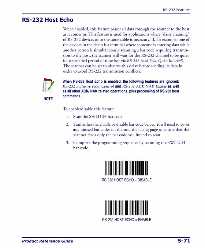
RS-232 Features
Product Reference Guide 5-71
RS-232 Host EchoWhen enabled, this feature passes all data through the scanner to the host as it comes in. This feature is used for applications where “daisy chaining” of RS-232 devices onto the same cable is necessary. If, for example, one of the devices in the chain is a terminal where someone is entering data while another person is simultaneously scanning a bar code requiring transmis-sion to the host, the scanner will wait for the RS-232 channel to be quiet for a specified period of time (set via RS-232 Host Echo Quiet Interval). The scanner can be set to observe this delay before sending its data in order to avoid RS-232 transmission conflicts.
To enable/disable this feature:
1. Scan the SWITCH bar code.
2. Scan either the enable or disable bar code below. You’ll need to cover any unused bar codes on this and the facing page to ensure that the scanner reads only the bar code you intend to scan.
3. Complete the programming sequence by scanning the SWITCH bar code.
RS-232 HOST ECHO = DISABLE
RS-232 HOST ECHO = ENABLE
NOTE
When RS-232 Host Echo is enabled, the following features are ignored: RS-232 Software Flow Control and RS-232 ACK NAK Enable as well as all other ACK/ NAK related operations, plus processing of RS-232 host commands.
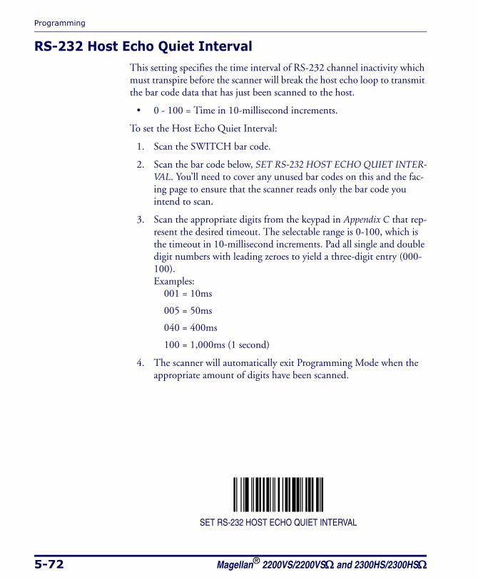
Programming
5-72 Magellan® 2200VS/2200VSΩ and 2300HS/2300HSΩ
RS-232 Host Echo Quiet IntervalThis setting specifies the time interval of RS-232 channel inactivity which must transpire before the scanner will break the host echo loop to transmit the bar code data that has just been scanned to the host.
• 0 - 100 = Time in 10-millisecond increments.
To set the Host Echo Quiet Interval:
1. Scan the SWITCH bar code.
2. Scan the bar code below, SET RS-232 HOST ECHO QUIET INTER-VAL. You’ll need to cover any unused bar codes on this and the fac-ing page to ensure that the scanner reads only the bar code you intend to scan.
3. Scan the appropriate digits from the keypad in Appendix C that rep-resent the desired timeout. The selectable range is 0-100, which is the timeout in 10-millisecond increments. Pad all single and double digit numbers with leading zeroes to yield a three-digit entry (000-100). Examples:
001 = 10ms
005 = 50ms
040 = 400ms
100 = 1,000ms (1 second)
4. The scanner will automatically exit Programming Mode when the appropriate amount of digits have been scanned.
SET RS-232 HOST ECHO QUIET INTERVAL
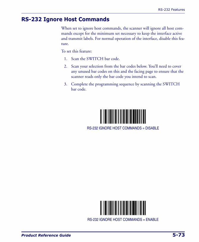
RS-232 Features
Product Reference Guide 5-73
RS-232 Ignore Host CommandsWhen set to ignore host commands, the scanner will ignore all host com-mands except for the minimum set necessary to keep the interface active and transmit labels. For normal operation of the interface, disable this fea-ture.
To set this feature:
1. Scan the SWITCH bar code.
2. Scan your selection from the bar codes below. You’ll need to cover any unused bar codes on this and the facing page to ensure that the scanner reads only the bar code you intend to scan.
3. Complete the programming sequence by scanning the SWITCH bar code.
RS-232 IGNORE HOST COMMANDS = DISABLE
RS-232 IGNORE HOST COMMANDS = ENABLE
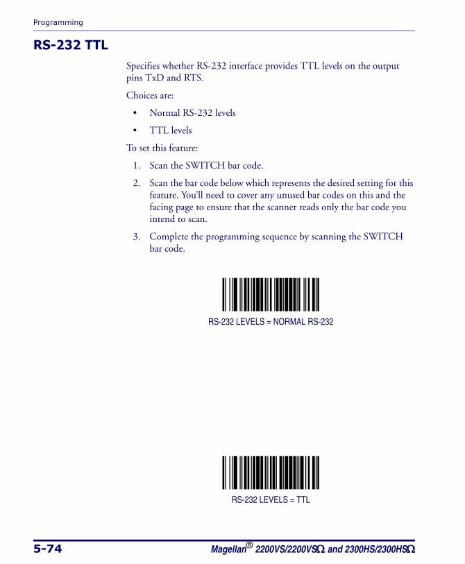
Programming
5-74 Magellan® 2200VS/2200VSΩ and 2300HS/2300HSΩ
RS-232 TTLSpecifies whether RS-232 interface provides TTL levels on the output pins TxD and RTS.
Choices are:
• Normal RS-232 levels
• TTL levels
To set this feature:
1. Scan the SWITCH bar code.
2. Scan the bar code below which represents the desired setting for this feature. You’ll need to cover any unused bar codes on this and the facing page to ensure that the scanner reads only the bar code you intend to scan.
3. Complete the programming sequence by scanning the SWITCH bar code.
RS-232 LEVELS = NORMAL RS-232
RS-232 LEVELS = TTL
RS-232 Features
Product Reference Guide 5-75
RS-232 TTL InvertEnables/disables inversion of TTL.
To set this feature:
1. Scan the SWITCH bar code.
2. Scan the bar code below which represents the desired setting for this feature. You’ll need to cover any unused bar codes on this and the facing page to ensure that the scanner reads only the bar code you intend to scan.
3. Complete the programming sequence by scanning the SWITCH bar code.
RS-232 TTL INVERT = DISABLE
RS-232 TTL INVERT = ENABLE
Programming
5-76 Magellan® 2200VS/2200VSΩ and 2300HS/2300HSΩ
RS-232 Beep on ASCII BELEnables/disables ability of scanner to beep (sound a good read tone) on receiving an ASCII BEL (07 hex).
• Disable
• Enable
To enable/disable this feature:
1. Scan the SWITCH bar code.
2. Scan either the enable or disable bar code below. You’ll need to cover any unused bar codes on this and the facing page to ensure that the scanner reads only the bar code you intend to scan.
3. Complete the programming sequence by scanning the SWITCH bar code.
RS-232 BEEP ON ASCII BEL = DISABLE
RS-232 BEEP ON ASCII BEL = ENABLE
RS-232 Features
Product Reference Guide 5-77
RS-232 Beep on Not on FileSelect for the host to beep (or not) when a not-on-file condition is detected by the host. This feature is also applicable to single cable RS-232.
RS-232 BEEP ON NOT ON FILE = DISABLE
ENABLE

Programming
5-78 Magellan® 2200VS/2200VSΩ and 2300HS/2300HSΩ
RS-232 ACK NAK EnableThis enables/disables the ability of the scanner to support the RS-232 ACK/NAK protocol. When configured, the scanner and/or host sends an “ACK” when it receives data properly, and sends “NAK” when the data is in error. Selections for this option are:
• Disable
• Label Transmission — the scanner expects an ACK/NAK response from the host when a label is sent)
• Host Acknowledgement — Enabled for Host Commands (the scan-ner will respond with ACK/NAK when the host sends a command)
• Label & Host — Enabled for both Label Transmission & Host Commands
To select the option for RS-232 ACK NAK Enable:
1. Scan the SWITCH bar code.
2. Scan the desired option from bar codes below and on the following page. You’ll need to cover any unused bar codes on this and the fac-ing page to ensure that the scanner reads only the bar code you intend to scan.
3. Complete the programming sequence by scanning the SWITCH bar code.
RS-232 ACK NAK = DISABLE
RS-232 ACK/NAK = LABEL TRANSMISSION
RS-232 Features
Product Reference Guide 5-79
RS-232 ACK NAK Enable — continuedRemember to cover any unused bar codes on this and the facing page to ensure that the scanner reads only the bar code you intend to scan.
RS-232 ACK/NAK = HOST ACKNOWLEDGEMENT
RS-232 ACK/NAK = LABEL & HOST
Programming
5-80 Magellan® 2200VS/2200VSΩ and 2300HS/2300HSΩ
RS-232 ACK CharacterThis feature specifies which ASCII character will be used as an ACK char-acter.
To specify the RS-232 ACK Character:
1. Scan the SWITCH bar code.
2. Scan the bar code, SET RS-232 ACK Character below. You’ll need to cover any unused bar codes on this and the facing page to ensure the scanner reads only the bar code you intend to scan.
3. Scan the appropriate digits from the keypad in Appendix C that rep-resent the hex designation for the desired character. A table contain-ing the ASCII Character Set and their corresponding Hex Values is available in the inside back cover of this manual. ASCII parameters must be input by scanning a pair of hexadecimal digits for the desired character. For example, if ASCII “A” were the desired ACK character, you would scan the digits “4”, then “1” (the ASCII corre-sponding hex value).
4. The scanner will automatically exit Programming Mode when the appropriate amount of digits/characters have been scanned.
SET RS-232 ACK Character
NOTE
DO NOT set this feature to use previously defined characters such as XON, XOFF or host commands as this will conflict with normal opera-tion of these characters. 8-bit data is not recognized when the feature, RS-232 Number of Data Bits, is set to 7 data bits.
RS-232 Features
Product Reference Guide 5-81
RS-232 NAK CharacterThis feature specifies which ASCII character will be used as a NAK char-acter.
To specify the RS-232 NAK Character:
1. Scan the SWITCH bar code.
2. Scan the bar code, SET RS-232 NAK Character below. You’ll need to cover any unused bar codes on this and the facing page to ensure the scanner reads only the bar code you intend to scan.
3. Scan the appropriate digits from the keypad in Appendix C that rep-resent the hex designation for the desired character. A table contain-ing the ASCII Character Set and their corresponding Hex Values is available in the inside back cover of this manual. ASCII parameters must be input by scanning a pair of hexadecimal digits for the desired character. For example, if ASCII “A” were the desired NAK character, you would scan the digits “4”, then “1” (the ASCII corre-sponding hex value).
4. The scanner will automatically exit Programming Mode when the appropriate amount of digits/characters have been scanned.
SET RS-232 NAK Character
NOTE
DO NOT set this feature to use previously defined characters such as XON, XOFF or host commands as this will conflict with normal operation of these characters. 8-bit data is not recognized when the feature, RS-232 Number of Data Bits, is set to 7 data bits.
Programming
5-82 Magellan® 2200VS/2200VSΩ and 2300HS/2300HSΩ
RS-232 Retry on ACK NAK TimeoutThis option specifies the action scanner performs on expiration of the RS-232 ACK NAK Timeout Value.
To set this feature:
1. Scan the SWITCH bar code.
2. Scan either the enable or disable bar code below. You’ll need to cover any unused bar codes on this and the facing page to ensure that the scanner reads only the bar code you intend to scan.
3. Complete the programming sequence by scanning the SWITCH bar code.
RS-232 RETRY ON ACK NAK TIMEOUT = DISABLE
RS-232 RETRY ON ACK NAK TIMEOUT = ENABLE
RS-232 Features
Product Reference Guide 5-83
RS-232 ACK NAK Timeout ValueThis item specifies the time the scanner will wait for an ACK character from the host following a label transmission.
• 0 = Infinite timeout
• 1 - 75 = Timeout in 200-millisecond increments
To set the ACK NAK Timeout Value:
1. Scan the SWITCH bar code.
2. Scan the bar code below, SET RS-232 ACK NAK TIMEOUT VALUE. You’ll need to cover any unused bar codes on this and the facing page to ensure that the scanner reads only the bar code you intend to scan.
3. Scan the appropriate digits from the keypad in Appendix C that rep-resent the desired timeout. A setting of 0 specifies an infinite time-out. The remaining selectable range is 1-75, which is the timeout in 200-millisecond increments. Pad all single digit numbers with a leading zero to yield a two-digit entry (00-75). Examples:
00 = Infinite timeout
01 = 200ms
05 = 1,000ms (1 second)
40 = 8,000ms (8 seconds)
75 = 15,000ms (15 seconds)
4. The scanner will automatically exit Programming Mode when the appropriate amount of digits have been scanned.
SET RS-232 ACK NAK TIMEOUT VALUE
Programming
5-84 Magellan® 2200VS/2200VSΩ and 2300HS/2300HSΩ
RS-232 ACK NAK Retry CountThis feature sets the number of times for the scanner to retry a label trans-mission under a retry condition.
To set the RS-232 ACK NAK Retry Count:
1. Scan the SWITCH bar code.
2. Scan the bar code, SET RS-232 ACK NAK RETRY COUNT below. You’ll need to cover any unused bar codes on this and the facing page to ensure that the scanner reads only the bar code you intend to scan.
3. Scan the appropriate digits from the keypad in Appendix C that rep-resent the desired number. The selectable range is 0-255 resets. Pad all single and double digit numbers with leading zeroes to yield a three-digit entry (000-255).
4. The scanner will automatically exit Programming Mode when the appropriate amount of digits have been scanned.
SET RS-232 ACK NAK RETRY COUNT
NOTE
A setting of 255 specifies “retry forever.”
RS-232 Features
Product Reference Guide 5-85
RS-232 ACK NAK Error HandlingThis item specifies the method the scanner will use to handle errors detected while waiting to receive the ACK character from the host. Errors include unrecognized host commands and communication errors such as parity or framing errors.
• Ignore Errors (recommended setting)
• Assume ACK (risk of lost label data)
• Assume NAK (risk of duplicate label)
To select the option for RS-232 ACK NAK Error Handling:
1. Scan the SWITCH bar code.
2. Scan the desired option from the bar codes below. You’ll need to cover any unused bar codes on this and the facing page to ensure that the scanner reads only the bar code you intend to scan.
3. Complete the programming sequence by scanning the SWITCH bar code.
RS-232 ACK NAK ERROR HANDLING = IGNORE ERRORS

Programming
5-86 Magellan® 2200VS/2200VSΩ and 2300HS/2300HSΩ
RS-232 ACK NAK Error Handling — continuedRemember to cover any unused bar codes on this and the facing page to ensure that the scanner reads only the bar code you intend to scan.
RS-232 ACK NAK ERROR HANDLING = ASSUME ACK
RS-232 ACK NAK ERROR HANDLING = ASSUME NAK
RS-232 Features
Product Reference Guide 5-87
RS-232 Label ID ControlThis feature specifies whether or not Label IDs are transmitted to the host and if so, whether to attach them as a prefix or suffix.
RS-232 LABEL ID CONTROL = DISABLE
RS-232 LABEL ID CONTROL = ENABLE AS PREFIX
Programming
5-88 Magellan® 2200VS/2200VSΩ and 2300HS/2300HSΩ
RS-232 Label ID Control — continuedRemember to cover any unused bar codes on this and the facing page to ensure that the scanner reads only the bar code you intend to scan.
RS-232 LABEL ID CONTROL = ENABLE AS SUFFIX
Single Cable RS-232 Options
Product Reference Guide 5-89
Single Cable RS-232 OptionsThe RS-232 Single Cable interface shares some configuration options with other RS-232 interfaces. Rather than repeat them in this section as Single Cable options, please find them referenced as follows:
• RS-232 Baud Rate on page 5-59
• RS-232 Number of Data Bits on page 5-63
• RS-232 Number of Stop Bits on page 5-64
• RS-232 Parity on page 5-65
• RS-232 Software Flow Control on page 5-70
• RS-232 Beep on Not on File on page 5-77
• RS-232 Beep on Not on File on page 5-77
• RS-232 Label ID Control on page 5-87
Programming
5-90 Magellan® 2200VS/2200VSΩ and 2300HS/2300HSΩ
Single Cable RS-232 RTS CTS SelectionSpecifies how RTS and CTS are used to control the data flow. RTS is con-trolled by the Scanner and can be continuously held high/low, or can be asserted during label transmission. The scanner looks at CTS, as the con-figuration values state, to determine when to send label data.
Choices are:
• Option 0 = RTS is held in low state and CTS is ignored
• Option 1 = RTS is held in high state and CTS is ignored
• Option 2 = Assert RTS and wait for CTS to be asserted
• Option 3 = Assert RTS and ignore CTS
• Option 4 = RTS held low, wait for CTS to be asserted
• Option 5 = RTS held high, wait for CTS to be asserted
To set this feature:
1. Scan the SWITCH bar code.
2. Scan a bar code below or on the following pages representing the desired option. You’ll need to cover any unused bar codes, as well as facing pages to ensure that the scanner reads only the bar code you intend to scan.
3. Complete the programming sequence by scanning the SWITCH bar code.
RTS CTS SELECTION = OPTION 0
RTS CTS SELECTION = OPTION 1
Single Cable RS-232 Options
Product Reference Guide 5-91
Single Cable RS-232 RTS CTS Selection — continuedRemember to cover any unused bar codes on this and the facing page to ensure that the scanner reads only the bar code you intend to scan.
RTS CTS SELECTION = OPTION 2
RTS CTS SELECTION = OPTION 3
Programming
5-92 Magellan® 2200VS/2200VSΩ and 2300HS/2300HSΩ
Single Cable RS-232 RTS CTS Selection — continuedRemember to cover any unused bar codes on this and the facing page to ensure that the scanner reads only the bar code you intend to scan.
RTS CTS SELECTION = OPTION 4
RTS CTS SELECTION = OPTION 5

Single Cable RS-232 Options
Product Reference Guide 5-93
Single Cable RS-232 Use BCCEnables/disables the ability of the scanner to use BCC.
To set this feature:
1. Scan the SWITCH bar code.
2. Scan either the enable or disable bar code below. You’ll need to cover any unused bar codes on this and the facing page to ensure that the scanner reads only the bar code you intend to scan.
3. Complete the programming sequence by scanning the SWITCH bar code.
SINGLE CABLE RS-232 USE BCC = DISABLE
SINGLE CABLE RS-232 USE BCC = ENABLE
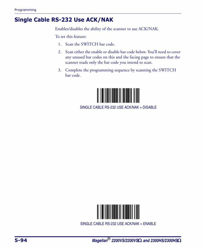
Programming
5-94 Magellan® 2200VS/2200VSΩ and 2300HS/2300HSΩ
Single Cable RS-232 Use ACK/NAKEnables/disables the ability of the scanner to use ACK/NAK.
To set this feature:
1. Scan the SWITCH bar code.
2. Scan either the enable or disable bar code below. You’ll need to cover any unused bar codes on this and the facing page to ensure that the scanner reads only the bar code you intend to scan.
3. Complete the programming sequence by scanning the SWITCH bar code.
SINGLE CABLE RS-232 USE ACK/NAK = DISABLE
SINGLE CABLE RS-232 USE ACK/NAK = ENABLE
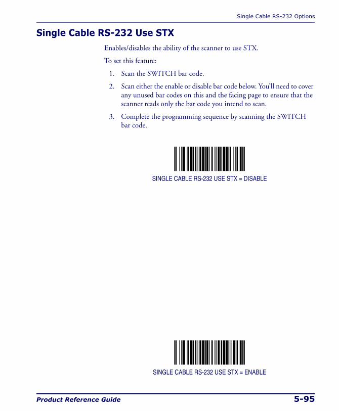
Single Cable RS-232 Options
Product Reference Guide 5-95
Single Cable RS-232 Use STXEnables/disables the ability of the scanner to use STX.
To set this feature:
1. Scan the SWITCH bar code.
2. Scan either the enable or disable bar code below. You’ll need to cover any unused bar codes on this and the facing page to ensure that the scanner reads only the bar code you intend to scan.
3. Complete the programming sequence by scanning the SWITCH bar code.
SINGLE CABLE RS-232 USE STX = DISABLE
SINGLE CABLE RS-232 USE STX = ENABLE
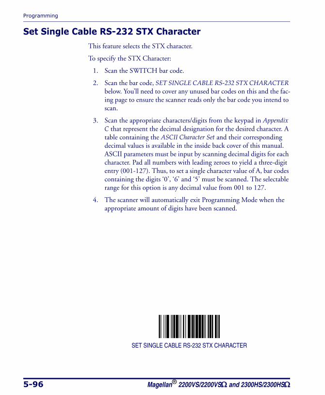
Programming
5-96 Magellan® 2200VS/2200VSΩ and 2300HS/2300HSΩ
Set Single Cable RS-232 STX CharacterThis feature selects the STX character.
To specify the STX Character:
1. Scan the SWITCH bar code.
2. Scan the bar code, SET SINGLE CABLE RS-232 STX CHARACTER below. You’ll need to cover any unused bar codes on this and the fac-ing page to ensure the scanner reads only the bar code you intend to scan.
3. Scan the appropriate characters/digits from the keypad in Appendix C that represent the decimal designation for the desired character. A table containing the ASCII Character Set and their corresponding decimal values is available in the inside back cover of this manual. ASCII parameters must be input by scanning decimal digits for each character. Pad all numbers with leading zeroes to yield a three-digit entry (001-127). Thus, to set a single character value of A, bar codes containing the digits ‘0’, ‘6’ and ‘5’ must be scanned. The selectable range for this option is any decimal value from 001 to 127.
4. The scanner will automatically exit Programming Mode when the appropriate amount of digits have been scanned.
SET SINGLE CABLE RS-232 STX CHARACTER

Single Cable RS-232 Options
Product Reference Guide 5-97
Single Cable RS-232 Use ETXEnables/disables the ability of the scanner to use ETX.
To set this feature:
1. Scan the SWITCH bar code.
2. Scan either the enable or disable bar code below. You’ll need to cover any unused bar codes on this and the facing page to ensure that the scanner reads only the bar code you intend to scan.
3. Complete the programming sequence by scanning the SWITCH bar code.
SINGLE CABLE RS-232 USE ETX = DISABLE
SINGLE CABLE RS-232 USE ETX = ENABLE

Programming
5-98 Magellan® 2200VS/2200VSΩ and 2300HS/2300HSΩ
Set Single Cable RS-232 ETX CharacterAllows selection of the ETX character.
To specify the ETX Character:
1. Scan the SWITCH bar code.
2. Scan the bar code, SET SINGLE CABLE RS-232 ETX CHARACTER below. You’ll need to cover any unused bar codes on this and the fac-ing page to ensure the scanner reads only the bar code you intend to scan.
3. Scan the appropriate characters/digits from the keypad in Appendix C that represent the decimal designation for the desired character. A table containing the ASCII Character Set and their corresponding decimal values is available in the inside back cover of this manual. ASCII parameters must be input by scanning decimal digits for each character. Pad all numbers with leading zeroes to yield a three-digit entry (001-127). Thus, to set a single character value of A, bar codes containing the digits ‘0’, ‘6’ and ‘5’ must be scanned. The selectable range for this option is any decimal value from 001 to 127.
4. The scanner will automatically exit Programming Mode when the appropriate amount of digits have been scanned.
SET SINGLE CABLE RS-232 ETX CHARACTER
PC Keyboard Wedge and USB Keyboard Interfaces
Product Reference Guide 5-99
PC Keyboard Wedge and USB Keyboard InterfacesThis section contains the following PC Keyboard Wedge and USB Key-board Interface parameters in the order listed:
• Connect to a Laptop/No Keyboard Attached (PC Keyboard Wedge ONLY)
• Send Control/Function Characters
• Caps Lock
• Country Mode
• Keyboard Wedge Intercharacter Delay (PC Keyboard Wedge ONLY)
• Quiet Interval (PC Keyboard Wedge ONLY)
NOTE
If the transmission parameters are configured such that a label results in no actual data to send, the label will be accepted, beeped, and no data transmit-ted.
Programming
5-100 Magellan® 2200VS/2200VSΩ and 2300HS/2300HSΩ
Connect to a Laptop/No Keyboard Attached
If no keyboard is attached, the scanner must provide the acknowledge sig-nal to the PC. In this case, enable the "Laptop/No External Keyboard" mode. If a keyboard is attached, enable "Keyboard Attached."
Laptop (no external keyboard) — provides the acknowledge signal to the PC when the scanner is connected to a laptop computer or when the scanner is operated with no external keyboard.
Keyboard attached — is enabled when the scanner is connected to a standard PC with an external keyboard.
LAPTOP (NO EXTERNAL KEYBOARD)
KEYBOARD ATTACHED
NOTE
This feature applies to PC Keyboard Wedge ONLY.
PC Keyboard Wedge and USB Keyboard Interfaces
Product Reference Guide 5-101
Send Control/Function CharactersOptions for this feature are:
Send Control Characters — transmits all ASCII characters except NUL (00h) .
Disable Control Characters — disabling this feature limits transmis-sion of ASCII characters to the following:
• Only ASCII characters between 20h..127h, plus.
• - Carriage Return (CR=0Dh)
• - BackSpace (BS=08h)
• - Right Tab (HT=09h)
• - Left Tab (0Bh)
• - Esc (1Bh)
Send Function Character — transmits characters 00H - IFH accord-ing to special function key mapping.
Scan the bar code belows below to select the applicable option for con-necting to a laptop or PC.
SEND CONTROL CHARACTERS

Programming
5-102 Magellan® 2200VS/2200VSΩ and 2300HS/2300HSΩ
Send Control/Function Characters — continuedRemember to cover any unused bar codes on this and the facing page to ensure that the scanner reads only the bar code you intend to scan.
DISABLE CONTROL CHARACTERS
SEND FUNCTION CHARACTER
PC Keyboard Wedge and USB Keyboard Interfaces
Product Reference Guide 5-103
Caps LockThree caps lock settings are available. These are:
Caps Lock Off — •sends character data to the host in normal format.
Caps Lock On — •sends character data to the host in reverse case (a.z) = (A.Z) (A.Z) = (a.z)
Use this feature if your keyboard's caps lock key is on.
Caps Lock = Shift-Lock — sends character data (to the host) in shifted case. Use this feature if you choose to use the keyboard with the shift lock key left on. For use with interface type G (IBM 3xxx 122-keyboard) ONLY.
CAPS LOCK: OFF
CAPS LOCK: ON
Programming
5-104 Magellan® 2200VS/2200VSΩ and 2300HS/2300HSΩ
Caps Lock — continuedRemember to cover any unused bar codes on this and the facing page to ensure that the scanner reads only the bar code you intend to scan.
CAPS LOCK: CAPS LOCK = SHIFT LOCK
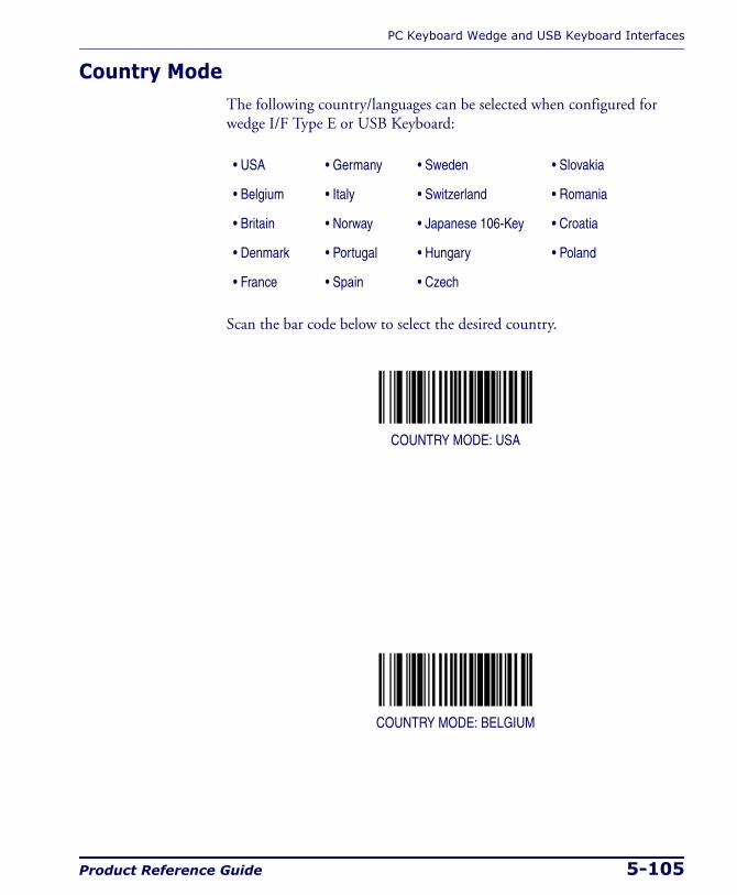
PC Keyboard Wedge and USB Keyboard Interfaces
Product Reference Guide 5-105
Country ModeThe following country/languages can be selected when configured for wedge I/F Type E or USB Keyboard:
Scan the bar code below to select the desired country.
COUNTRY MODE: USA
COUNTRY MODE: BELGIUM
• USA • Germany • Sweden • Slovakia
• Belgium • Italy • Switzerland • Romania
• Britain • Norway • Japanese 106-Key • Croatia
• Denmark • Portugal • Hungary • Poland
• France • Spain • Czech
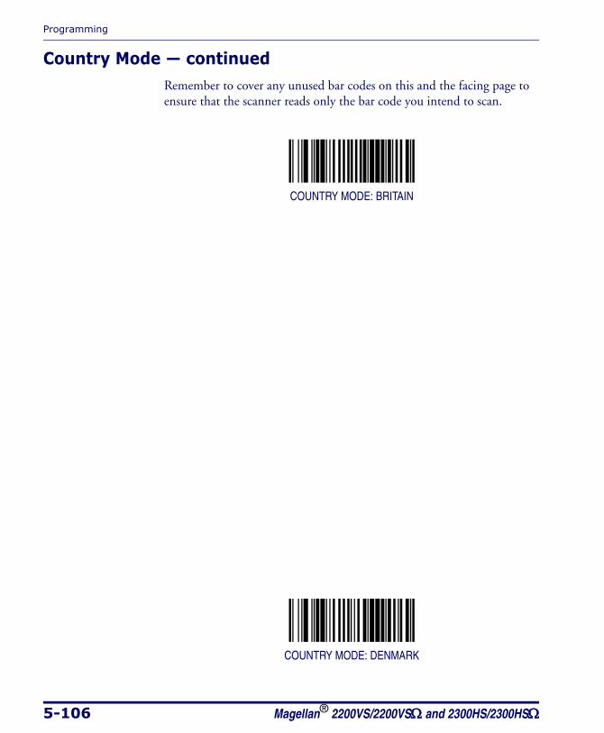
Programming
5-106 Magellan® 2200VS/2200VSΩ and 2300HS/2300HSΩ
Country Mode — continuedRemember to cover any unused bar codes on this and the facing page to ensure that the scanner reads only the bar code you intend to scan.
COUNTRY MODE: BRITAIN
COUNTRY MODE: DENMARK
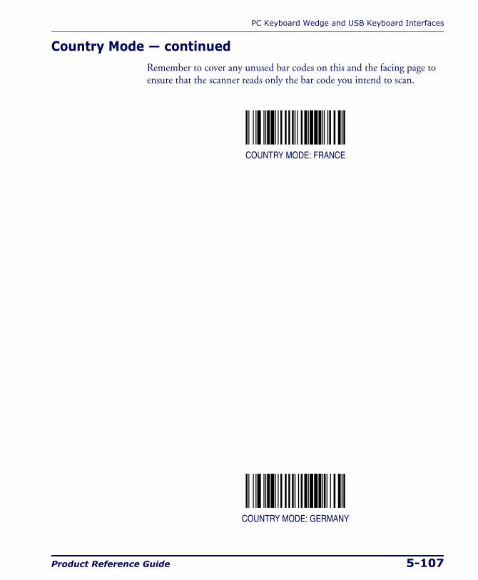
PC Keyboard Wedge and USB Keyboard Interfaces
Product Reference Guide 5-107
Country Mode — continuedRemember to cover any unused bar codes on this and the facing page to ensure that the scanner reads only the bar code you intend to scan.
COUNTRY MODE: FRANCE
COUNTRY MODE: GERMANY

Programming
5-108 Magellan® 2200VS/2200VSΩ and 2300HS/2300HSΩ
Country Mode — continuedRemember to cover any unused bar codes on this and the facing page to ensure that the scanner reads only the bar code you intend to scan.
COUNTRY MODE: ITALY
COUNTRY MODE: NORWAY

PC Keyboard Wedge and USB Keyboard Interfaces
Product Reference Guide 5-109
Country Mode — continuedRemember to cover any unused bar codes on this and the facing page to ensure that the scanner reads only the bar code you intend to scan.
COUNTRY MODE: PORTUGAL
COUNTRY MODE: SPAIN

Programming
5-110 Magellan® 2200VS/2200VSΩ and 2300HS/2300HSΩ
Country Mode — continuedRemember to cover any unused bar codes on this and the facing page to ensure that the scanner reads only the bar code you intend to scan.
COUNTRY MODE: SWEDEN
COUNTRY MODE: SWITZERLAND
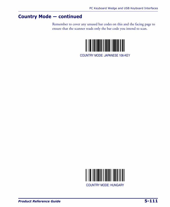
PC Keyboard Wedge and USB Keyboard Interfaces
Product Reference Guide 5-111
Country Mode — continuedRemember to cover any unused bar codes on this and the facing page to ensure that the scanner reads only the bar code you intend to scan.
COUNTRY MODE: JAPANESE 106-KEY
COUNTRY MODE: HUNGARY

Programming
5-112 Magellan® 2200VS/2200VSΩ and 2300HS/2300HSΩ
Country Mode — continuedRemember to cover any unused bar codes on this and the facing page to ensure that the scanner reads only the bar code you intend to scan.
COUNTRY MODE: CZECH
COUNTRY MODE: SLOVAKIA
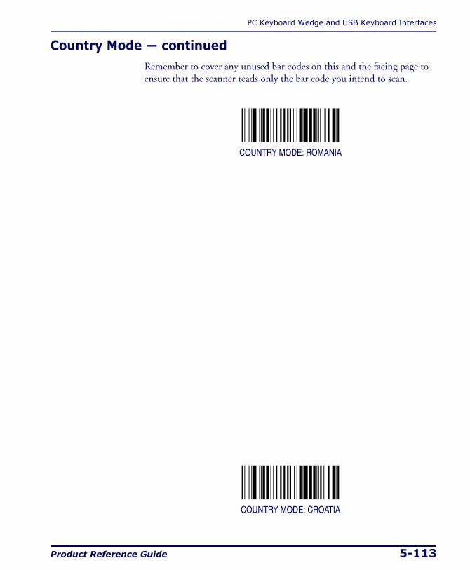
PC Keyboard Wedge and USB Keyboard Interfaces
Product Reference Guide 5-113
Country Mode — continuedRemember to cover any unused bar codes on this and the facing page to ensure that the scanner reads only the bar code you intend to scan.
COUNTRY MODE: ROMANIA
COUNTRY MODE: CROATIA
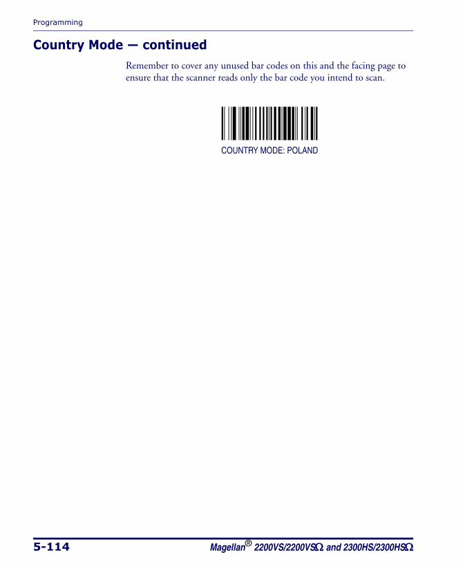
Programming
5-114 Magellan® 2200VS/2200VSΩ and 2300HS/2300HSΩ
Country Mode — continuedRemember to cover any unused bar codes on this and the facing page to ensure that the scanner reads only the bar code you intend to scan.
COUNTRY MODE: POLAND
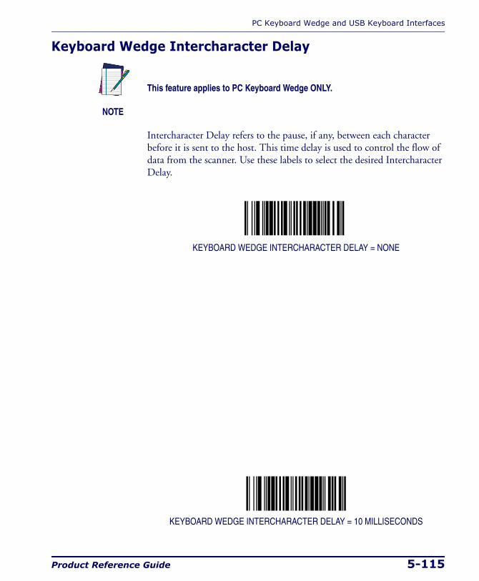
PC Keyboard Wedge and USB Keyboard Interfaces
Product Reference Guide 5-115
Keyboard Wedge Intercharacter Delay
Intercharacter Delay refers to the pause, if any, between each character before it is sent to the host. This time delay is used to control the flow of data from the scanner. Use these labels to select the desired Intercharacter Delay.
KEYBOARD WEDGE INTERCHARACTER DELAY = NONE
KEYBOARD WEDGE INTERCHARACTER DELAY = 10 MILLISECONDS
NOTE
This feature applies to PC Keyboard Wedge ONLY.
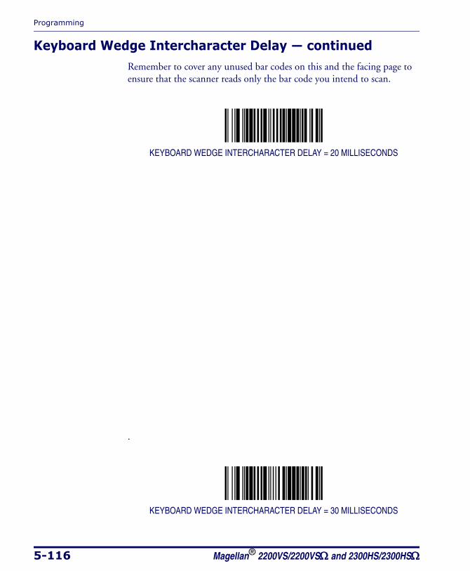
Programming
5-116 Magellan® 2200VS/2200VSΩ and 2300HS/2300HSΩ
Keyboard Wedge Intercharacter Delay — continuedRemember to cover any unused bar codes on this and the facing page to ensure that the scanner reads only the bar code you intend to scan.
KEYBOARD WEDGE INTERCHARACTER DELAY = 20 MILLISECONDS
.
KEYBOARD WEDGE INTERCHARACTER DELAY = 30 MILLISECONDS
PC Keyboard Wedge and USB Keyboard Interfaces
Product Reference Guide 5-117
Keyboard Wedge Intercharacter Delay — continuedRemember to cover any unused bar codes on this and the facing page to ensure that the scanner reads only the bar code you intend to scan.
KEYBOARD WEDGE INTERCHARACTER DELAY = 40 MILLISECONDS
.
KEYBOARD WEDGE INTERCHARACTER DELAY = 60 MILLISECONDS
Programming
5-118 Magellan® 2200VS/2200VSΩ and 2300HS/2300HSΩ
Keyboard Wedge Intercharacter Delay — continuedRemember to cover any unused bar codes on this and the facing page to ensure that the scanner reads only the bar code you intend to scan.
KEYBOARD WEDGE INTERCHARACTER DELAY = 80 MILLISECONDS
.
KEYBOARD WEDGE INTERCHARACTER DELAY = 100 MILLISECONDS
PC Keyboard Wedge and USB Keyboard Interfaces
Product Reference Guide 5-119
Quiet Interval
Quiet Interval is the amount of time to look for keyboard activity before the scanner breaks the keyboard connection in order to transmit data to the host.
QUIET INTERVAL = 10 MILLISECONDS
.
QUIET INTERVAL = 20 MILLISECONDS
NOTE
This feature applies to PC Keyboard Wedge ONLY.
Programming
5-120 Magellan® 2200VS/2200VSΩ and 2300HS/2300HSΩ
Quiet Interval — continuedRemember to cover any unused bar codes on this and the facing page to ensure that the scanner reads only the bar code you intend to scan.
QUIET INTERVAL = 50 MILLISECONDS
.
QUIET INTERVAL = 100 MILLISECONDS
PC Keyboard Wedge and USB Keyboard Interfaces
Product Reference Guide 5-121
Quiet Interval — continuedRemember to cover any unused bar codes on this and the facing page to ensure that the scanner reads only the bar code you intend to scan.
QUIET INTERVAL = 200 MILLISECONDS
.
QUIET INTERVAL = 500 MILLISECONDS
Programming
5-122 Magellan® 2200VS/2200VSΩ and 2300HS/2300HSΩ
Quiet Interval — continuedRemember to cover any unused bar codes on this and the facing page to ensure that the scanner reads only the bar code you intend to scan.
QUIET INTERVAL = ONE SECOND
Symbology Programming
Product Reference Guide 5-123
Symbology Programming
UPC-A EnableEnables/disables the ability of the scanner to decode UPC-A labels.
To set this feature:
1. Scan the SWITCH bar code.
2. Scan either the enable or disable bar code below. You’ll need to cover any unused bar codes on this and the facing page to ensure that the scanner reads only the bar code you intend to scan.
3. Complete the programming sequence by scanning the SWITCH bar code.
UPC-A = DISABLE
UPC-A = ENABLE
NOTE
If the scanner’s interface type must be changed, always be sure that interface configuration is the FIRST item scanned during a program-ming session. (Changing an interface type resets ALL other configura-tion items — including symbology programming — to the factory default for that interface type.)
Programming
5-124 Magellan® 2200VS/2200VSΩ and 2300HS/2300HSΩ
UPC-A Number System Character TransmissionEnables/disables transmission of a UPC-A number system character.
To set this feature:
1. Scan the SWITCH bar code.
2. Scan either the enable or disable bar code below. You’ll need to cover any unused bar codes on this and the facing page to ensure that the scanner reads only the bar code you intend to scan.
3. Complete the programming sequence by scanning the SWITCH bar code.
UPC-A NUMBER SYSTEM CHARACTER TRANSMISSION = DISABLE
UPC-A NUMBER SYSTEM CHARACTER TRANSMISSION = ENABLE
NOTE
This feature MUST be enabled for IBM interfaces for proper function.
This item is ignored when the advanced feature, Full Label Edit, is enabled.
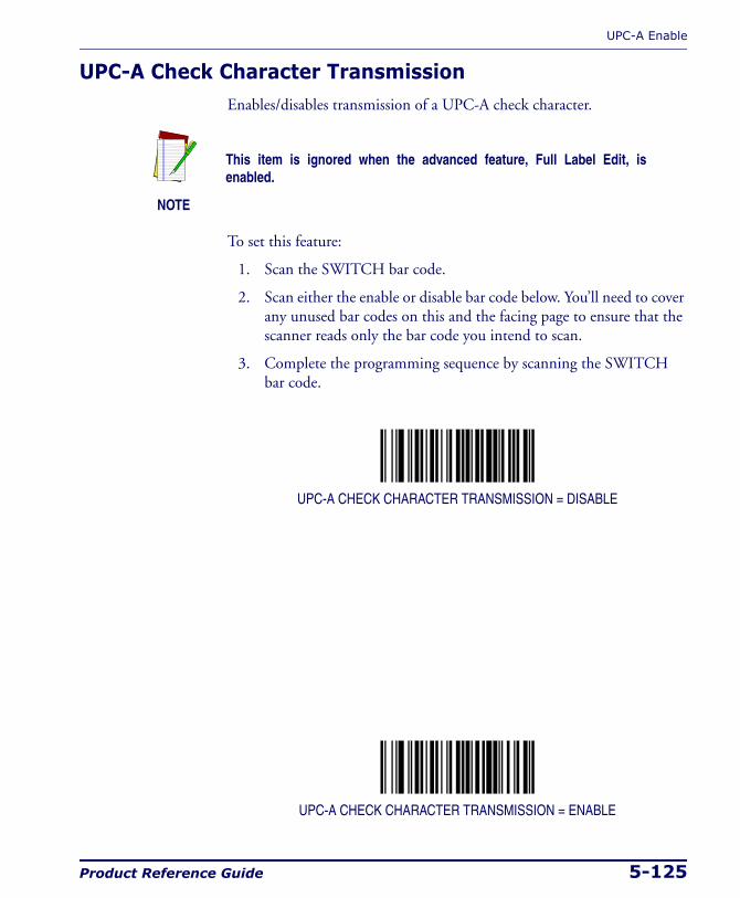
UPC-A Enable
Product Reference Guide 5-125
UPC-A Check Character TransmissionEnables/disables transmission of a UPC-A check character.
To set this feature:
1. Scan the SWITCH bar code.
2. Scan either the enable or disable bar code below. You’ll need to cover any unused bar codes on this and the facing page to ensure that the scanner reads only the bar code you intend to scan.
3. Complete the programming sequence by scanning the SWITCH bar code.
UPC-A CHECK CHARACTER TRANSMISSION = DISABLE
UPC-A CHECK CHARACTER TRANSMISSION = ENABLE
NOTE
This item is ignored when the advanced feature, Full Label Edit, is enabled.
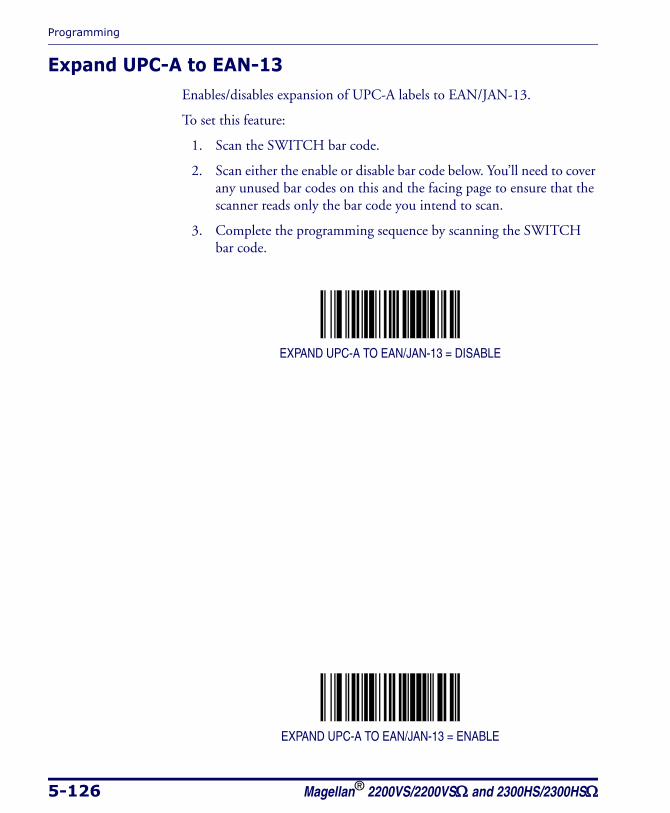
Programming
5-126 Magellan® 2200VS/2200VSΩ and 2300HS/2300HSΩ
Expand UPC-A to EAN-13Enables/disables expansion of UPC-A labels to EAN/JAN-13.
To set this feature:
1. Scan the SWITCH bar code.
2. Scan either the enable or disable bar code below. You’ll need to cover any unused bar codes on this and the facing page to ensure that the scanner reads only the bar code you intend to scan.
3. Complete the programming sequence by scanning the SWITCH bar code.
EXPAND UPC-A TO EAN/JAN-13 = DISABLE
EXPAND UPC-A TO EAN/JAN-13 = ENABLE

UPC-A Enable
Product Reference Guide 5-127
UPC/EAN AIM IDThis feature enables/disables transmission of the UPC/EAN AIM symbol-ogy identifier.
To set this feature:
1. Scan the SWITCH bar code.
2. Scan your selection from the bar codes below. You’ll need to cover any unused bar codes on this and the facing page to ensure that the scanner reads only the bar code you intend to scan.
3. Complete the programming sequence by scanning the SWITCH bar code.
UPC/EAN AIM ID = DISABLE
UPC/EAN AIM ID = ENABLE
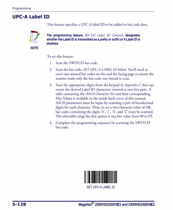
Programming
5-128 Magellan® 2200VS/2200VSΩ and 2300HS/2300HSΩ
UPC-A Label IDThis feature specifies a UPC-A label ID to be added to bar code data.
To set this feature:
1. Scan the SWITCH bar code.
2. Scan the bar code, SET UPC-A LABEL ID below. You’ll need to cover any unused bar codes on this and the facing page to ensure the scanner reads only the bar code you intend to scan.
3. Scan the appropriate digits from the keypad in Appendix C that rep-resent the desired Label ID characters; entered as two hex pairs. A table containing the ASCII Character Set and their corresponding Hex Values is available in the inside back cover of this manual. ASCII parameters must be input by scanning a pair of hexadecimal digits for each character. Thus, to set a two-character value of AB, bar codes containing the digits ‘4’, ‘1’, ‘4’, and ‘2’ must be scanned. The selectable range for this option is any hex value from 00 to FF.
4. Complete the programming sequence by scanning the SWITCH bar code.
SET UPC-A LABEL ID
NOTE
The programming feature, RS-232 Label ID Control, designates whether the Label ID is transmitted as a prefix or suffix or if Label ID is disabled.
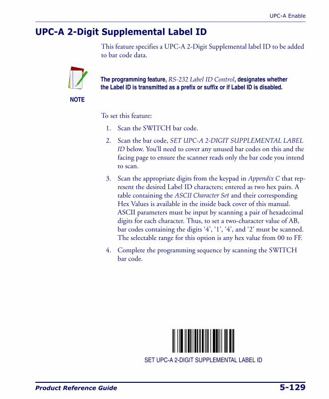
UPC-A Enable
Product Reference Guide 5-129
UPC-A 2-Digit Supplemental Label IDThis feature specifies a UPC-A 2-Digit Supplemental label ID to be added to bar code data.
To set this feature:
1. Scan the SWITCH bar code.
2. Scan the bar code, SET UPC-A 2-DIGIT SUPPLEMENTAL LABEL ID below. You’ll need to cover any unused bar codes on this and the facing page to ensure the scanner reads only the bar code you intend to scan.
3. Scan the appropriate digits from the keypad in Appendix C that rep-resent the desired Label ID characters; entered as two hex pairs. A table containing the ASCII Character Set and their corresponding Hex Values is available in the inside back cover of this manual. ASCII parameters must be input by scanning a pair of hexadecimal digits for each character. Thus, to set a two-character value of AB, bar codes containing the digits ‘4’, ‘1’, ‘4’, and ‘2’ must be scanned. The selectable range for this option is any hex value from 00 to FF.
4. Complete the programming sequence by scanning the SWITCH bar code.
SET UPC-A 2-DIGIT SUPPLEMENTAL LABEL ID
NOTE
The programming feature, RS-232 Label ID Control, designates whether the Label ID is transmitted as a prefix or suffix or if Label ID is disabled.
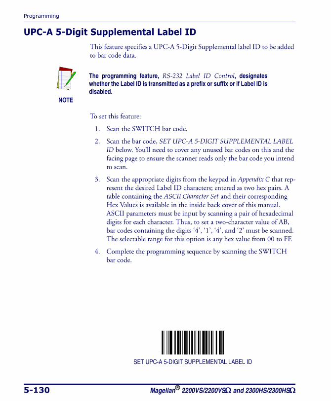
Programming
5-130 Magellan® 2200VS/2200VSΩ and 2300HS/2300HSΩ
UPC-A 5-Digit Supplemental Label IDThis feature specifies a UPC-A 5-Digit Supplemental label ID to be added to bar code data.
To set this feature:
1. Scan the SWITCH bar code.
2. Scan the bar code, SET UPC-A 5-DIGIT SUPPLEMENTAL LABEL ID below. You’ll need to cover any unused bar codes on this and the facing page to ensure the scanner reads only the bar code you intend to scan.
3. Scan the appropriate digits from the keypad in Appendix C that rep-resent the desired Label ID characters; entered as two hex pairs. A table containing the ASCII Character Set and their corresponding Hex Values is available in the inside back cover of this manual. ASCII parameters must be input by scanning a pair of hexadecimal digits for each character. Thus, to set a two-character value of AB, bar codes containing the digits ‘4’, ‘1’, ‘4’, and ‘2’ must be scanned. The selectable range for this option is any hex value from 00 to FF.
4. Complete the programming sequence by scanning the SWITCH bar code.
SET UPC-A 5-DIGIT SUPPLEMENTAL LABEL ID
NOTE
The programming feature, RS-232 Label ID Control, designates whether the Label ID is transmitted as a prefix or suffix or if Label ID is disabled.

UPC-A Enable
Product Reference Guide 5-131
UPC-A 128 Supplemental Label IDThis feature specifies a UPC-A 128 Supplemental label ID to be added to bar code data.
To set this feature:
1. Scan the SWITCH bar code.
2. Scan the bar code, SET UPC-A 128 SUPPLEMENTAL LABEL ID below. You’ll need to cover any unused bar codes on this and the fac-ing page to ensure the scanner reads only the bar code you intend to scan.
3. Scan the appropriate digits from the keypad in Appendix C that rep-resent the desired Label ID characters; entered as two hex pairs. A table containing the ASCII Character Set and their corresponding Hex Values is available in the inside back cover of this manual. ASCII parameters must be input by scanning a pair of hexadecimal digits for each character. Thus, to set a two-character value of AB, bar codes containing the digits ‘4’, ‘1’, ‘4’, and ‘2’ must be scanned. The selectable range for this option is any hex value from 00 to FF.
4. Complete the programming sequence by scanning the SWITCH bar code.
SET UPC-A 128 SUPPLEMENTAL LABEL ID
NOTE
The programming feature, RS-232 Label ID Control, designates whether the Label ID is transmitted as a prefix or suffix or if Label ID is disabled.
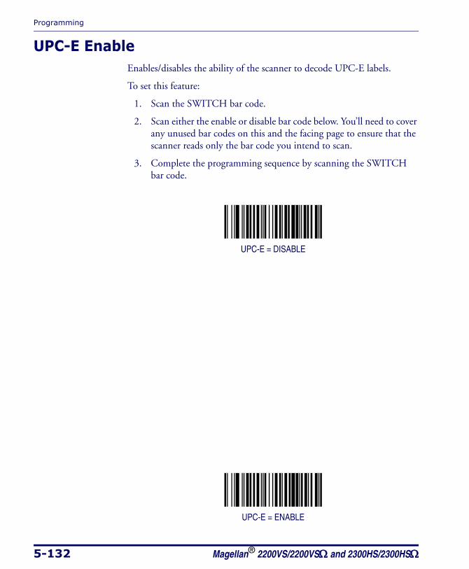
Programming
5-132 Magellan® 2200VS/2200VSΩ and 2300HS/2300HSΩ
UPC-E EnableEnables/disables the ability of the scanner to decode UPC-E labels.
To set this feature:
1. Scan the SWITCH bar code.
2. Scan either the enable or disable bar code below. You’ll need to cover any unused bar codes on this and the facing page to ensure that the scanner reads only the bar code you intend to scan.
3. Complete the programming sequence by scanning the SWITCH bar code.
UPC-E = DISABLE
UPC-E = ENABLE
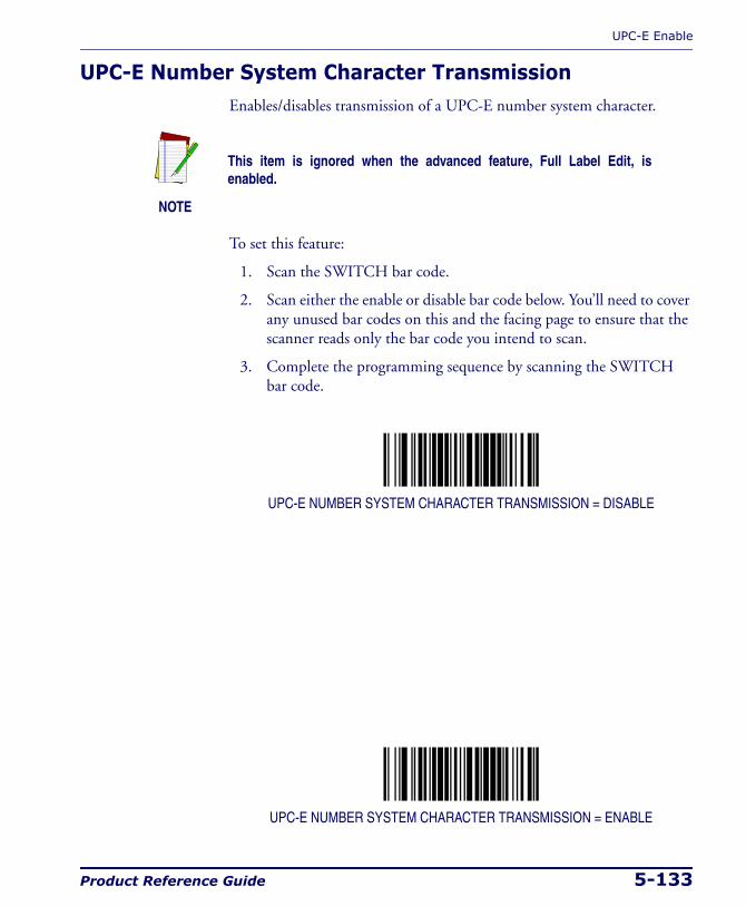
UPC-E Enable
Product Reference Guide 5-133
UPC-E Number System Character TransmissionEnables/disables transmission of a UPC-E number system character.
To set this feature:
1. Scan the SWITCH bar code.
2. Scan either the enable or disable bar code below. You’ll need to cover any unused bar codes on this and the facing page to ensure that the scanner reads only the bar code you intend to scan.
3. Complete the programming sequence by scanning the SWITCH bar code.
UPC-E NUMBER SYSTEM CHARACTER TRANSMISSION = DISABLE
UPC-E NUMBER SYSTEM CHARACTER TRANSMISSION = ENABLE
NOTE
This item is ignored when the advanced feature, Full Label Edit, is enabled.
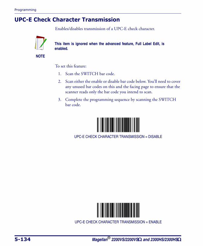
Programming
5-134 Magellan® 2200VS/2200VSΩ and 2300HS/2300HSΩ
UPC-E Check Character TransmissionEnables/disables transmission of a UPC-E check character.
To set this feature:
1. Scan the SWITCH bar code.
2. Scan either the enable or disable bar code below. You’ll need to cover any unused bar codes on this and the facing page to ensure that the scanner reads only the bar code you intend to scan.
3. Complete the programming sequence by scanning the SWITCH bar code.
UPC-E CHECK CHARACTER TRANSMISSION = DISABLE
UPC-E CHECK CHARACTER TRANSMISSION = ENABLE
NOTE
This item is ignored when the advanced feature, Full Label Edit, is enabled.
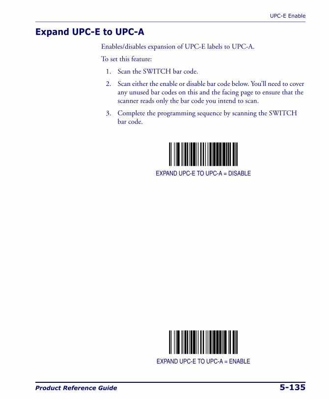
UPC-E Enable
Product Reference Guide 5-135
Expand UPC-E to UPC-AEnables/disables expansion of UPC-E labels to UPC-A.
To set this feature:
1. Scan the SWITCH bar code.
2. Scan either the enable or disable bar code below. You’ll need to cover any unused bar codes on this and the facing page to ensure that the scanner reads only the bar code you intend to scan.
3. Complete the programming sequence by scanning the SWITCH bar code.
EXPAND UPC-E TO UPC-A = DISABLE
EXPAND UPC-E TO UPC-A = ENABLE

Programming
5-136 Magellan® 2200VS/2200VSΩ and 2300HS/2300HSΩ
Expand UPC-E to EAN-13Enables/disables expansion of UPC-E labels to EAN/JAN-13.
To set this feature:
1. Scan the SWITCH bar code.
2. Scan either the enable or disable bar code below. You’ll need to cover any unused bar codes on this and the facing page to ensure that the scanner reads only the bar code you intend to scan.
3. Complete the programming sequence by scanning the SWITCH bar code.
EXPAND UPC-E TO EAN/JAN-13 = DISABLE
EXPAND UPC-E TO EAN/JAN-13 = ENABLE
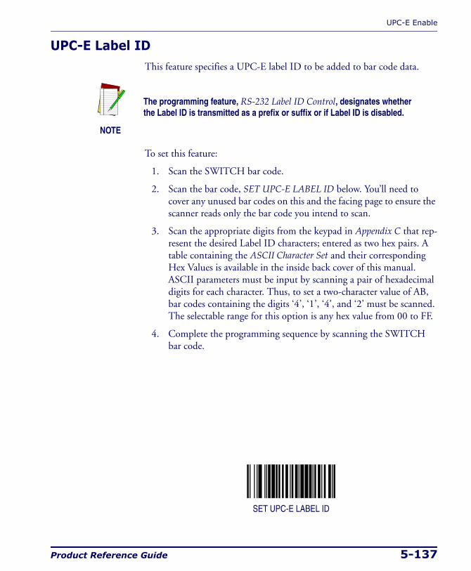
UPC-E Enable
Product Reference Guide 5-137
UPC-E Label IDThis feature specifies a UPC-E label ID to be added to bar code data.
To set this feature:
1. Scan the SWITCH bar code.
2. Scan the bar code, SET UPC-E LABEL ID below. You’ll need to cover any unused bar codes on this and the facing page to ensure the scanner reads only the bar code you intend to scan.
3. Scan the appropriate digits from the keypad in Appendix C that rep-resent the desired Label ID characters; entered as two hex pairs. A table containing the ASCII Character Set and their corresponding Hex Values is available in the inside back cover of this manual. ASCII parameters must be input by scanning a pair of hexadecimal digits for each character. Thus, to set a two-character value of AB, bar codes containing the digits ‘4’, ‘1’, ‘4’, and ‘2’ must be scanned. The selectable range for this option is any hex value from 00 to FF.
4. Complete the programming sequence by scanning the SWITCH bar code.
SET UPC-E LABEL ID
NOTE
The programming feature, RS-232 Label ID Control, designates whether the Label ID is transmitted as a prefix or suffix or if Label ID is disabled.

Programming
5-138 Magellan® 2200VS/2200VSΩ and 2300HS/2300HSΩ
UPC-E 2-Digit Supplemental Label IDThis feature specifies a UPC-E 2-Digit Supplemental label ID to be added to bar code data.
To set this feature:
1. Scan the SWITCH bar code.
2. Scan the bar code, SET UPC-E 2-DIGIT SUPPLEMENTAL LABEL ID below. You’ll need to cover any unused bar codes on this and the facing page to ensure the scanner reads only the bar code you intend to scan.
3. Scan the appropriate digits from the keypad in Appendix C that rep-resent the desired Label ID characters; entered as two hex pairs. A table containing the ASCII Character Set and their corresponding Hex Values is available in the inside back cover of this manual. ASCII parameters must be input by scanning a pair of hexadecimal digits for each character. Thus, to set a two-character value of AB, bar codes containing the digits ‘4’, ‘1’, ‘4’, and ‘2’ must be scanned. The selectable range for this option is any hex value from 00 to FF.
4. Complete the programming sequence by scanning the SWITCH bar code.
SET UPC-E 2-DIGIT SUPPLEMENTAL LABEL ID
NOTE
The programming feature, RS-232 Label ID Control, designates whether the Label ID is transmitted as a prefix or suffix or if Label ID is disabled.
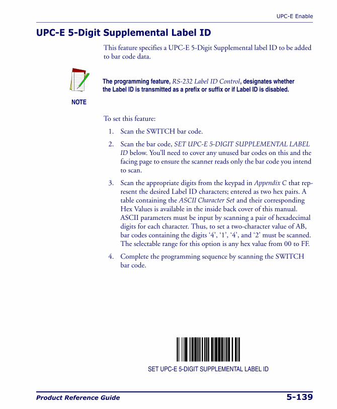
UPC-E Enable
Product Reference Guide 5-139
UPC-E 5-Digit Supplemental Label IDThis feature specifies a UPC-E 5-Digit Supplemental label ID to be added to bar code data.
To set this feature:
1. Scan the SWITCH bar code.
2. Scan the bar code, SET UPC-E 5-DIGIT SUPPLEMENTAL LABEL ID below. You’ll need to cover any unused bar codes on this and the facing page to ensure the scanner reads only the bar code you intend to scan.
3. Scan the appropriate digits from the keypad in Appendix C that rep-resent the desired Label ID characters; entered as two hex pairs. A table containing the ASCII Character Set and their corresponding Hex Values is available in the inside back cover of this manual. ASCII parameters must be input by scanning a pair of hexadecimal digits for each character. Thus, to set a two-character value of AB, bar codes containing the digits ‘4’, ‘1’, ‘4’, and ‘2’ must be scanned. The selectable range for this option is any hex value from 00 to FF.
4. Complete the programming sequence by scanning the SWITCH bar code.
SET UPC-E 5-DIGIT SUPPLEMENTAL LABEL ID
NOTE
The programming feature, RS-232 Label ID Control, designates whether the Label ID is transmitted as a prefix or suffix or if Label ID is disabled.
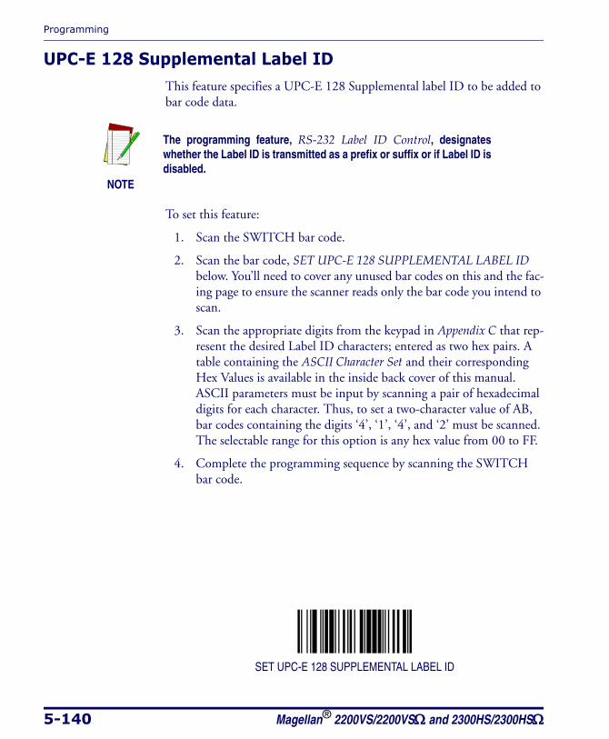
Programming
5-140 Magellan® 2200VS/2200VSΩ and 2300HS/2300HSΩ
UPC-E 128 Supplemental Label IDThis feature specifies a UPC-E 128 Supplemental label ID to be added to bar code data.
To set this feature:
1. Scan the SWITCH bar code.
2. Scan the bar code, SET UPC-E 128 SUPPLEMENTAL LABEL ID below. You’ll need to cover any unused bar codes on this and the fac-ing page to ensure the scanner reads only the bar code you intend to scan.
3. Scan the appropriate digits from the keypad in Appendix C that rep-resent the desired Label ID characters; entered as two hex pairs. A table containing the ASCII Character Set and their corresponding Hex Values is available in the inside back cover of this manual. ASCII parameters must be input by scanning a pair of hexadecimal digits for each character. Thus, to set a two-character value of AB, bar codes containing the digits ‘4’, ‘1’, ‘4’, and ‘2’ must be scanned. The selectable range for this option is any hex value from 00 to FF.
4. Complete the programming sequence by scanning the SWITCH bar code.
SET UPC-E 128 SUPPLEMENTAL LABEL ID
NOTE
The programming feature, RS-232 Label ID Control, designates whether the Label ID is transmitted as a prefix or suffix or if Label ID is disabled.
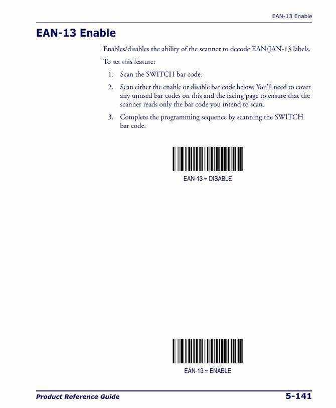
EAN-13 Enable
Product Reference Guide 5-141
EAN-13 EnableEnables/disables the ability of the scanner to decode EAN/JAN-13 labels.
To set this feature:
1. Scan the SWITCH bar code.
2. Scan either the enable or disable bar code below. You’ll need to cover any unused bar codes on this and the facing page to ensure that the scanner reads only the bar code you intend to scan.
3. Complete the programming sequence by scanning the SWITCH bar code.
EAN-13 = DISABLE
EAN-13 = ENABLE

Programming
5-142 Magellan® 2200VS/2200VSΩ and 2300HS/2300HSΩ
EAN-13 First Character TransmissionEnables/disables transmission of EAN/JAN-13 first character.
To set this feature:
1. Scan the SWITCH bar code.
2. Scan either the enable or disable bar code below. You’ll need to cover any unused bar codes on this and the facing page to ensure that the scanner reads only the bar code you intend to scan.
3. Complete the programming sequence by scanning the SWITCH bar code.
EAN-13 FIRST CHARACTER TRANSMISSION = DISABLE
EAN-13 FIRST CHARACTER TRANSMISSION = ENABLE
NOTE
This item is ignored when the advanced feature, Full Label Edit, is enabled.
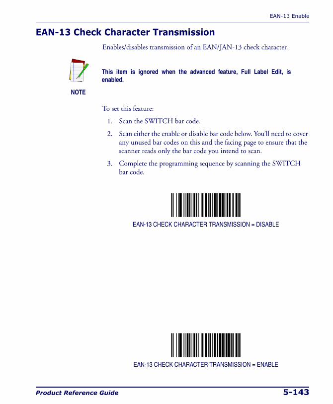
EAN-13 Enable
Product Reference Guide 5-143
EAN-13 Check Character TransmissionEnables/disables transmission of an EAN/JAN-13 check character.
To set this feature:
1. Scan the SWITCH bar code.
2. Scan either the enable or disable bar code below. You’ll need to cover any unused bar codes on this and the facing page to ensure that the scanner reads only the bar code you intend to scan.
3. Complete the programming sequence by scanning the SWITCH bar code.
EAN-13 CHECK CHARACTER TRANSMISSION = DISABLE
EAN-13 CHECK CHARACTER TRANSMISSION = ENABLE
NOTE
This item is ignored when the advanced feature, Full Label Edit, is enabled.
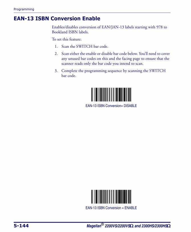
Programming
5-144 Magellan® 2200VS/2200VSΩ and 2300HS/2300HSΩ
EAN-13 ISBN Conversion EnableEnables/disables conversion of EAN/JAN-13 labels starting with 978 to Bookland ISBN labels.
To set this feature:
1. Scan the SWITCH bar code.
2. Scan either the enable or disable bar code below. You’ll need to cover any unused bar codes on this and the facing page to ensure that the scanner reads only the bar code you intend to scan.
3. Complete the programming sequence by scanning the SWITCH bar code.
EAN-13 ISBN Conversion= DISABLE
EAN-13 ISBN Conversion = ENABLE
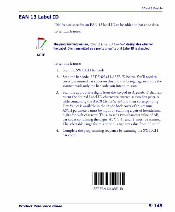
EAN-13 Enable
Product Reference Guide 5-145
EAN 13 Label IDThis feature specifies an EAN 13 label ID to be added to bar code data.
To set this feature:
To set this feature:
1. Scan the SWITCH bar code.
2. Scan the bar code, SET EAN 13 LABEL ID below. You’ll need to cover any unused bar codes on this and the facing page to ensure the scanner reads only the bar code you intend to scan.
3. Scan the appropriate digits from the keypad in Appendix C that rep-resent the desired Label ID characters; entered as two hex pairs. A table containing the ASCII Character Set and their corresponding Hex Values is available in the inside back cover of this manual. ASCII parameters must be input by scanning a pair of hexadecimal digits for each character. Thus, to set a two-character value of AB, bar codes containing the digits ‘4’, ‘1’, ‘4’, and ‘2’ must be scanned. The selectable range for this option is any hex value from 00 to FF.
4. Complete the programming sequence by scanning the SWITCH bar code.
SET EAN 13 LABEL ID
NOTE
The programming feature, RS-232 Label ID Control, designates whether the Label ID is transmitted as a prefix or suffix or if Label ID is disabled.
Programming
5-146 Magellan® 2200VS/2200VSΩ and 2300HS/2300HSΩ
EAN-13 2-Digit Supplemental Label IDThis feature specifies an EAN-13 2-Digit Supplemental label ID to be added to bar code data.
To set this feature:
1. Scan the SWITCH bar code.
2. Scan the bar code, SET EAN-13 2-DIGIT SUPPLEMENTAL LABEL ID below. You’ll need to cover any unused bar codes on this and the facing page to ensure the scanner reads only the bar code you intend to scan.
3. Scan the appropriate digits from the keypad in Appendix C that rep-resent the desired Label ID characters; entered as two hex pairs. A table containing the ASCII Character Set and their corresponding Hex Values is available in the inside back cover of this manual. ASCII parameters must be input by scanning a pair of hexadecimal digits for each character. Thus, to set a two-character value of AB, bar codes containing the digits ‘4’, ‘1’, ‘4’, and ‘2’ must be scanned. The selectable range for this option is any hex value from 00 to FF.
4. Complete the programming sequence by scanning the SWITCH bar code.
SET EAN-13 2-DIGIT SUPPLEMENTAL LABEL ID
NOTE
The programming feature, RS-232 Label ID Control, designates whether the Label ID is transmitted as a prefix or suffix or if Label ID is disabled.
EAN-13 Enable
Product Reference Guide 5-147
EAN-13 5-Digit Supplemental Label IDThis feature specifies an EAN-13 5-Digit Supplemental label ID to be added to bar code data.
To set this feature:
1. Scan the SWITCH bar code.
2. Scan the bar code, SET EAN-13 5-DIGIT SUPPLEMENTAL LABEL ID below. You’ll need to cover any unused bar codes on this and the facing page to ensure the scanner reads only the bar code you intend to scan.
3. Scan the appropriate digits from the keypad in Appendix C that rep-resent the desired Label ID characters; entered as two hex pairs. A table containing the ASCII Character Set and their corresponding Hex Values is available in the inside back cover of this manual. ASCII parameters must be input by scanning a pair of hexadecimal digits for each character. Thus, to set a two-character value of AB, bar codes containing the digits ‘4’, ‘1’, ‘4’, and ‘2’ must be scanned. The selectable range for this option is any hex value from 00 to FF.
4. Complete the programming sequence by scanning the SWITCH bar code.
SET EAN-13 5-DIGIT SUPPLEMENTAL LABEL ID
NOTE
The programming feature, RS-232 Label ID Control, designates whether the Label ID is transmitted as a prefix or suffix or if Label ID is disabled.

Programming
5-148 Magellan® 2200VS/2200VSΩ and 2300HS/2300HSΩ
EAN-13 128 Supplemental Label IDThis feature specifies an EAN-13 128 Supplemental label ID to be added to bar code data.
To set this feature:
1. Scan the SWITCH bar code.
2. Scan the bar code, SET EAN-13 128 SUPPLEMENTAL LABEL ID = DISABLE below. You’ll need to cover any unused bar codes on this and the facing page to ensure the scanner reads only the bar code you intend to scan.
3. Scan the appropriate digits from the keypad in Appendix C that rep-resent the desired Label ID characters; entered as two hex pairs. A table containing the ASCII Character Set and their corresponding Hex Values is available in the inside back cover of this manual. ASCII parameters must be input by scanning a pair of hexadecimal digits for each character. Thus, to set a two-character value of AB, bar codes containing the digits ‘4’, ‘1’, ‘4’, and ‘2’ must be scanned. The selectable range for this option is any hex value from 00 to FF.
4. Complete the programming sequence by scanning the SWITCH bar code.
SET EAN-13 128 SUPPLEMENTAL LABEL ID = DISABLE
NOTE
The programming feature, RS-232 Label ID Control, designates whether the Label ID is transmitted as a prefix or suffix or if Label ID is disabled.

EAN-13 Enable
Product Reference Guide 5-149
Bookland AIM IDThis feature enables/disables transmission of the Bookland AIM symbol-ogy identifier.
To set this feature:
1. Scan the SWITCH bar code.
2. Scan your selection from the bar codes below. You’ll need to cover any unused bar codes on this and the facing page to ensure that the scanner reads only the bar code you intend to scan.
3. Complete the programming sequence by scanning the SWITCH bar code.
BOOKLAND AIM ID = DISABLE
BOOKLAND AIM ID = ENABLE

Programming
5-150 Magellan® 2200VS/2200VSΩ and 2300HS/2300HSΩ
Bookland Label IDThis feature specifies a Bookland label ID to be added to bar code data.
To set this feature:
1. Scan the SWITCH bar code.
2. Scan the bar code, SET BOOKLAND LABEL ID below. You’ll need to cover any unused bar codes on this and the facing page to ensure the scanner reads only the bar code you intend to scan.
3. Scan the appropriate digits from the keypad in Appendix C that rep-resent the desired Label ID characters; entered as two hex pairs. A table containing the ASCII Character Set and their corresponding Hex Values is available in the inside back cover of this manual. ASCII parameters must be input by scanning a pair of hexadecimal digits for each character. Thus, to set a two-character value of AB, bar codes containing the digits ‘4’, ‘1’, ‘4’, and ‘2’ must be scanned. The selectable range for this option is any hex value from 00 to FF.
4. Complete the programming sequence by scanning the SWITCH bar code.
SET BOOKLAND LABEL ID
NOTE
The programming feature, RS-232 Label ID Control, designates whether the Label ID is transmitted as a prefix or suffix or if Label ID is disabled.
EAN-8 Enable
Product Reference Guide 5-151
EAN-8 EnableEnables/disables the ability of the scanner to decode EAN/JAN-8 labels.
To set this feature:
1. Scan the SWITCH bar code.
2. Scan either the enable or disable bar code below. You’ll need to cover any unused bar codes on this and the facing page to ensure that the scanner reads only the bar code you intend to scan.
3. Complete the programming sequence by scanning the SWITCH bar code.
EAN-8 = DISABLE
EAN-8 = ENABLE

Programming
5-152 Magellan® 2200VS/2200VSΩ and 2300HS/2300HSΩ
EAN-8 Check Character TransmissionEnables/disables transmission of an EAN/JAN-8 check character.
To set this feature:
1. Scan the SWITCH bar code.
2. Scan either the enable or disable bar code below. You’ll need to cover any unused bar codes on this and the facing page to ensure that the scanner reads only the bar code you intend to scan.
3. Complete the programming sequence by scanning the SWITCH bar code.
EAN-8 CHECK CHARACTER TRANSMISSION = DISABLE
EAN-8 CHECK CHARACTER TRANSMISSION = ENABLE
NOTE
This item is ignored when the advanced feature, Full Label Edit, is enabled.
EAN-8 Enable
Product Reference Guide 5-153
Expand EAN-8 to EAN-13Enables/disables expansion of EAN/JAN-8 labels to EAN/JAN-13.
To set this feature:
1. Scan the SWITCH bar code.
2. Scan either the enable or disable bar code below. You’ll need to cover any unused bar codes on this and the facing page to ensure that the scanner reads only the bar code you intend to scan.
3. Complete the programming sequence by scanning the SWITCH bar code.
EXPAND EAN/JAN-8 TO EAN/JAN-13 = DISABLE
EXPAND EAN/JAN-8 TO EAN/JAN-13 = ENABLE
Programming
5-154 Magellan® 2200VS/2200VSΩ and 2300HS/2300HSΩ
EAN 8 Label IDThis feature specifies an EAN 8 label ID to be added to bar code data.
To set this feature:
To set this feature:
1. Scan the SWITCH bar code.
2. Scan the bar code, SET EAN 8 LABEL ID below. You’ll need to cover any unused bar codes on this and the facing page to ensure the scan-ner reads only the bar code you intend to scan.
3. Scan the appropriate digits from the keypad in Appendix C that rep-resent the desired Label ID characters; entered as two hex pairs. A table containing the ASCII Character Set and their corresponding Hex Values is available in the inside back cover of this manual. ASCII parameters must be input by scanning a pair of hexadecimal digits for each character. Thus, to set a two-character value of AB, bar codes containing the digits ‘4’, ‘1’, ‘4’, and ‘2’ must be scanned. The selectable range for this option is any hex value from 00 to FF.
4. Complete the programming sequence by scanning the SWITCH bar code.
SET EAN 8 LABEL ID
NOTE
The programming feature, RS-232 Label ID Control, designates whether the Label ID is transmitted as a prefix or suffix or if Label ID is disabled.
EAN-8 Enable
Product Reference Guide 5-155
EAN-8 2-Digit Supplemental Label IDThis feature specifies an EAN-8 2-Digit Supplemental label ID to be added to bar code data.
To set this feature:
1. Scan the SWITCH bar code.
2. Scan the bar code, SET EAN-8 2-DIGIT SUPPLEMENTAL LABEL ID below. You’ll need to cover any unused bar codes on this and the facing page to ensure the scanner reads only the bar code you intend to scan.
3. Scan the appropriate digits from the keypad in Appendix C that rep-resent the desired Label ID characters; entered as two hex pairs. A table containing the ASCII Character Set and their corresponding Hex Values is available in the inside back cover of this manual. ASCII parameters must be input by scanning a pair of hexadecimal digits for each character. Thus, to set a two-character value of AB, bar codes containing the digits ‘4’, ‘1’, ‘4’, and ‘2’ must be scanned. The selectable range for this option is any hex value from 00 to FF.
4. Complete the programming sequence by scanning the SWITCH bar code.
SET EAN-8 2-DIGIT SUPPLEMENTAL LABEL ID
NOTE
The programming feature, RS-232 Label ID Control, designates whether the Label ID is transmitted as a prefix or suffix or if Label ID is disabled.

Programming
5-156 Magellan® 2200VS/2200VSΩ and 2300HS/2300HSΩ
EAN-8 5-Digit Supplemental Label IDThis feature specifies an EAN-8 5-Digit Supplemental label ID to be added to bar code data.
To set this feature:
1. Scan the SWITCH bar code.
2. Scan the bar code, SET EAN-8 5-DIGIT SUPPLEMENTAL LABEL ID below. You’ll need to cover any unused bar codes on this and the facing page to ensure the scanner reads only the bar code you intend to scan.
3. Scan the appropriate digits from the keypad in Appendix C that rep-resent the desired Label ID characters; entered as two hex pairs. A table containing the ASCII Character Set and their corresponding Hex Values is available in the inside back cover of this manual. ASCII parameters must be input by scanning a pair of hexadecimal digits for each character. Thus, to set a two-character value of AB, bar codes containing the digits ‘4’, ‘1’, ‘4’, and ‘2’ must be scanned. The selectable range for this option is any hex value from 00 to FF.
4. Complete the programming sequence by scanning the SWITCH bar code.
SET EAN-8 5-DIGIT SUPPLEMENTAL LABEL ID
NOTE
The programming feature, RS-232 Label ID Control, designates whether the Label ID is transmitted as a prefix or suffix or if Label ID is disabled.
EAN-8 Enable
Product Reference Guide 5-157
EAN-8 128 Supplemental Label IDThis feature specifies an EAN-8 128 Supplemental label ID to be added to bar code data.
To set this feature:
1. Scan the SWITCH bar code.
2. Scan the bar code, SET EAN-8 128 SUPPLEMENTAL LABEL ID below. You’ll need to cover any unused bar codes on this and the fac-ing page to ensure the scanner reads only the bar code you intend to scan.
3. Scan the appropriate digits from the keypad in Appendix C that rep-resent the desired Label ID characters; entered as two hex pairs. A table containing the ASCII Character Set and their corresponding Hex Values is available in the inside back cover of this manual. ASCII parameters must be input by scanning a pair of hexadecimal digits for each character. Thus, to set a two-character value of AB, bar codes containing the digits ‘4’, ‘1’, ‘4’, and ‘2’ must be scanned. The selectable range for this option is any hex value from 00 to FF.
4. Complete the programming sequence by scanning the SWITCH bar code.
SET EAN-8 128 SUPPLEMENTAL LABEL ID
NOTE
The programming feature, RS-232 Label ID Control, designates whether the Label ID is transmitted as a prefix or suffix or if Label ID is disabled.
Programming
5-158 Magellan® 2200VS/2200VSΩ and 2300HS/2300HSΩ
EAN-8 Decoding LevelsDecoding levels allow the decoder to be set to perform at one of four selectable levels:
• Very Conservative — Slower scan time, virtually eleminates mis-reads. The most secure setting.
• Slightly More Aggressive — Faster scanning, more aggressive, yet minimizes misreads.
• Moderately Aggressive — Even faster scanning, even more aggres-sive.
• Very Aggressive — Fastest scan speed, most aggressive.
To set this feature:
1. Scan the SWITCH bar code.
2. Scan the bar code representing the desired option on the following pages. You’ll need to cover any unused bar codes on facing pages to ensure that the scanner reads only the bar code you intend to scan.
3. Complete the programming sequence by scanning the SWITCH bar code.
CAUTION
Use caution when setting this feature, as the aggressive settings for this fea-ture allow a higher potential for misreads.
NOTE
It is important to note that the default for this feature is the “Slightly More Aggressive” setting. For default settings for other features, see Appendix E.
EAN-8 Enable
Product Reference Guide 5-159
EAN-8 Decoding Levels — continuedRemember to cover any unused bar codes on this and the facing page to ensure that the scanner reads only the bar code you intend to scan.
EAN-8 DECODING LEVELS = VERY CONSERVATIVE
EAN-8 DECODING LEVELS = SLIGHTLY MORE AGGRESSIVE
Programming
5-160 Magellan® 2200VS/2200VSΩ and 2300HS/2300HSΩ
EAN-8 Decoding Levels — continuedRemember to cover any unused bar codes on this and the facing page to ensure that the scanner reads only the bar code you intend to scan.
EAN-8 DECODING LEVELS = MODERATELY AGGRESSIVE
EAN-8 DECODING LEVELS = VERY AGGRESSIVE
Other UPC/EAN Options
Product Reference Guide 5-161
Other UPC/EAN OptionsThe following pages contain other selectable features for UPC/EAN sym-bologies:
• UPC/EAN Reconstruction
• Price Weight Check
• Enable EAN Two Label
• Addons
• UPC-A and EAN-13 Decoding Levels
Programming
5-162 Magellan® 2200VS/2200VSΩ and 2300HS/2300HSΩ
UPC/EAN ReconstructionEnables/disables the ability of the scanner to decode a class of UPC/EAN labels with voids. The label voids may be caused by printing defects or physical damage. This feature may be helpful in environments with in-store printed labels.
To set this feature:
1. Scan the SWITCH bar code.
2. Scan either the enable or disable bar code below. You’ll need to cover any unused bar codes on this and the facing page to ensure that the scanner reads only the bar code you intend to scan.
Complete the programming sequence by scanning the SWITCH bar code.
UPC/EAN RECONSTRUCTION = DISABLE
UPC/EAN RECONSTRUCTION = ENABLE
CAUTION
Enabling this feature increases the potential of misreads.
Other UPC/EAN Options
Product Reference Guide 5-163
Price Weight CheckEnables/disables calculation and verification of price/weight check digits. Applies to all UPC-A and EAN/JAN-13 labels with eligible1 Number Sys-tem/First Character digits.
Options are:
• Disable
• 4-digit price/weight
• 5-digit price/weight
• 4-digit European price/weight
• 5-digit European price/weight
To set this feature:
1. Scan the SWITCH bar code.
2. Scan the bar code representing the desired option below or on the following pages. You’ll need to cover any unused bar codes on facing pages to ensure that the scanner reads only the bar code you intend to scan.
3. Complete the programming sequence by scanning the SWITCH bar code.
PRICE WEIGHT CHECK = DISABLE
1. Price Weight Check generally applies to UPC-A labels with a Number System Digit of 2 and EAN/JAN-13 labels with a First Character of 2. There are a total of six flag digits corresponding to the six types. Checking applies depending upon which type is enabled.
Programming
5-164 Magellan® 2200VS/2200VSΩ and 2300HS/2300HSΩ
Price Weight Check — continuedRemember to cover any unused bar codes on this and the facing page to ensure that the scanner reads only the bar code you intend to scan.
PRICE WEIGHT CHECK = 4-DIGIT PRICE/WEIGHT
PRICE WEIGHT CHECK = 5-DIGIT PRICE/WEIGHT
Other UPC/EAN Options
Product Reference Guide 5-165
Price Weight Check — continuedRemember to cover any unused bar codes on this and the facing page to ensure that the scanner reads only the bar code you intend to scan.
PRICE WEIGHT CHECK = 4-DIGIT EUROPEAN PRICE/WEIGHT
PRICE WEIGHT CHECK = 5-DIGIT EUROPEAN PRICE/WEIGHT
Programming
5-166 Magellan® 2200VS/2200VSΩ and 2300HS/2300HSΩ
Enable EAN Two LabelEnables/disables the ability of the scanner to decode EAN two-label pairs.
To set this feature:
1. Scan the SWITCH bar code.
2. Scan either the enable or disable bar code below. You’ll need to cover any unused bar codes on this and the facing page to ensure that the scanner reads only the bar code you intend to scan.
3. Complete the programming sequence by scanning the SWITCH bar code.
EAN TWO LABEL = DISABLE
EAN TWO LABEL = ENABLE
NOTE
Contact Customer Support for details about advanced programming for this feature.
Other UPC/EAN Options
Product Reference Guide 5-167
Addons
The scanner is capable of processing different types of addon codes, including:
• 2-Digit Supplemental
• 5-Digit Supplemental
Options are provided on the following pages for your convenience:
• Disable all addons — The scanner will not look for or read addons.
• Optional 2-Digit and 5-Digit Supplemental — Bar codes can be read which include 2-Digit or 5-Digit Supplementals, however, it is not required that addons be included in bar codes.
To set this feature:
1. Scan the SWITCH bar code.
2. Scan the bar code representing the desired option on this and the following page. You’ll need to cover any unused bar codes on facing pages to ensure that the scanner reads only the bar code you intend to scan.
3. Complete the programming sequence by scanning the SWITCH bar code.
ADDONS = DISABLE
NOTE
Contact customer support for advanced programming of optional and conditional addons.
Programming
5-168 Magellan® 2200VS/2200VSΩ and 2300HS/2300HSΩ
Addons — continuedRemember to cover any unused bar codes on this and the facing page to ensure that the scanner reads only the bar code you intend to scan.
ADDONS = OPTIONAL 2-DIGIT AND 5-DIGIT SUPPLEMENTAL
Other UPC/EAN Options
Product Reference Guide 5-169
UPC-A and EAN-13 Decoding LevelsDecoding levels allow the decoder to be set to perform at one of four selectable levels:
• Very Conservative — Slower scan time, virtually eleminates mis-reads. The most secure setting.
• Slightly More Aggressive — Faster scanning, more aggressive, yet minimizes misreads.
• Moderately Aggressive — Even faster scanning, even more aggres-sive.
• Very Aggressive — Fastest scan speed, most aggressive.
To set this feature:
1. Scan the SWITCH bar code.
2. Scan the bar code representing the desired option on the following pages. You’ll need to cover any unused bar codes on facing pages to ensure that the scanner reads only the bar code you intend to scan.
3. Complete the programming sequence by scanning the SWITCH bar code.
CAUTION
Use caution when setting this feature, as the aggressive settings for this fea-ture allow a higher potential for misreads.
NOTE
It is important to note that the default for this feature is the “Slightly More Aggressive” setting. For default settings for other features, see Appendix E.
Programming
5-170 Magellan® 2200VS/2200VSΩ and 2300HS/2300HSΩ
UPC-A and EAN-13 Decoding Levels — continuedRemember to cover any unused bar codes on this and the facing page to ensure that the scanner reads only the bar code you intend to scan.
UPC-A/EAN-13 DECODING LEVELS = VERY CONSERVATIVE
UPC-A/EAN-13 DECODING LEVELS = SLIGHTLY MORE AGGRESSIVE
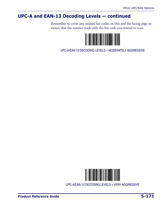
Other UPC/EAN Options
Product Reference Guide 5-171
UPC-A and EAN-13 Decoding Levels — continuedRemember to cover any unused bar codes on this and the facing page to ensure that the scanner reads only the bar code you intend to scan.
UPC-A/EAN-13 DECODING LEVELS = MODERATELY AGGRESSIVE
UPC-A/EAN-13 DECODING LEVELS = VERY AGGRESSIVE
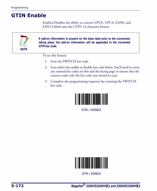
Programming
5-172 Magellan® 2200VS/2200VSΩ and 2300HS/2300HSΩ
GTIN EnableEnables/Disables the ability to convert UPCE, UPCA, EAN8, and EAN13 labels into the GTIN 14-character format.
To set this feature:
1. Scan the SWITCH bar code.
2. Scan either the enable or disable bar code below. You’ll need to cover any unused bar codes on this and the facing page to ensure that the scanner reads only the bar code you intend to scan.
3. Complete the programming sequence by scanning the SWITCH bar code.
GTIN = DISABLE
GTIN = ENABLE
NOTE
If add-on information is present on the base label prior to the conversion taking place, the add-on information will be appended to the converted GTIN bar code.
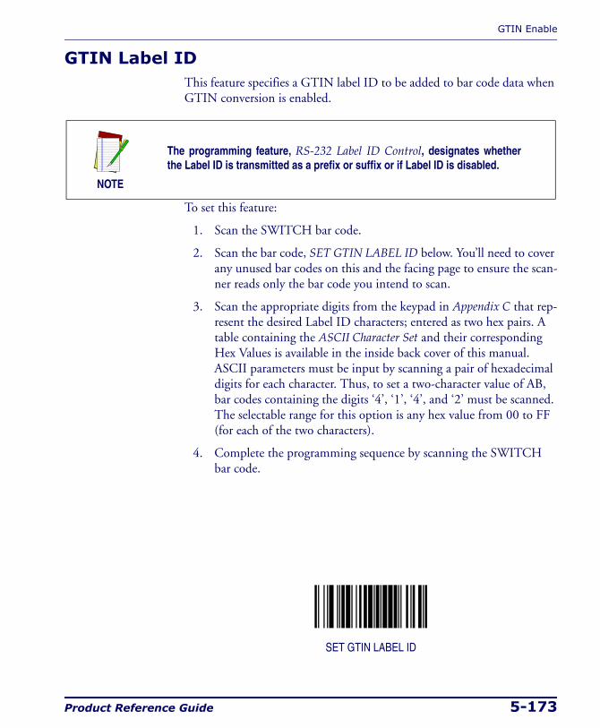
GTIN Enable
Product Reference Guide 5-173
GTIN Label IDThis feature specifies a GTIN label ID to be added to bar code data when GTIN conversion is enabled.
To set this feature:
1. Scan the SWITCH bar code.
2. Scan the bar code, SET GTIN LABEL ID below. You’ll need to cover any unused bar codes on this and the facing page to ensure the scan-ner reads only the bar code you intend to scan.
3. Scan the appropriate digits from the keypad in Appendix C that rep-resent the desired Label ID characters; entered as two hex pairs. A table containing the ASCII Character Set and their corresponding Hex Values is available in the inside back cover of this manual. ASCII parameters must be input by scanning a pair of hexadecimal digits for each character. Thus, to set a two-character value of AB, bar codes containing the digits ‘4’, ‘1’, ‘4’, and ‘2’ must be scanned. The selectable range for this option is any hex value from 00 to FF (for each of the two characters).
4. Complete the programming sequence by scanning the SWITCH bar code.
SET GTIN LABEL ID
NOTE
The programming feature, RS-232 Label ID Control, designates whether the Label ID is transmitted as a prefix or suffix or if Label ID is disabled.
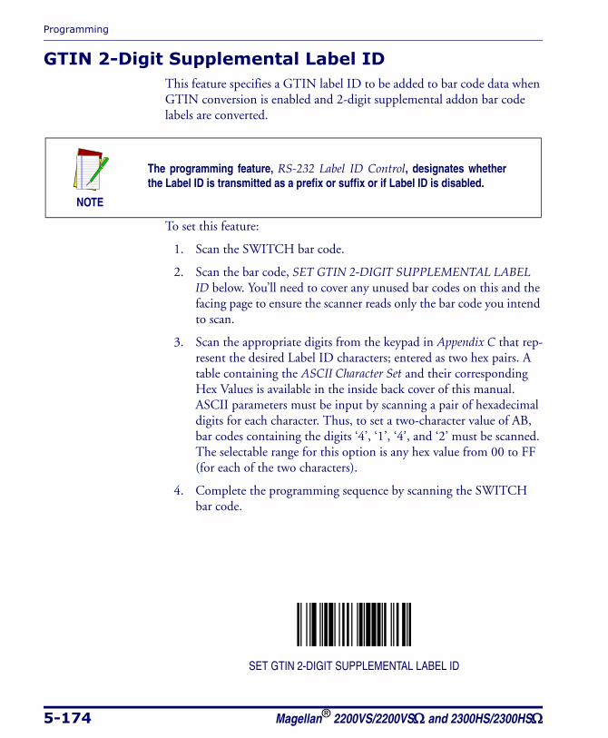
Programming
5-174 Magellan® 2200VS/2200VSΩ and 2300HS/2300HSΩ
GTIN 2-Digit Supplemental Label IDThis feature specifies a GTIN label ID to be added to bar code data when GTIN conversion is enabled and 2-digit supplemental addon bar code labels are converted.
To set this feature:
1. Scan the SWITCH bar code.
2. Scan the bar code, SET GTIN 2-DIGIT SUPPLEMENTAL LABEL ID below. You’ll need to cover any unused bar codes on this and the facing page to ensure the scanner reads only the bar code you intend to scan.
3. Scan the appropriate digits from the keypad in Appendix C that rep-resent the desired Label ID characters; entered as two hex pairs. A table containing the ASCII Character Set and their corresponding Hex Values is available in the inside back cover of this manual. ASCII parameters must be input by scanning a pair of hexadecimal digits for each character. Thus, to set a two-character value of AB, bar codes containing the digits ‘4’, ‘1’, ‘4’, and ‘2’ must be scanned. The selectable range for this option is any hex value from 00 to FF (for each of the two characters).
4. Complete the programming sequence by scanning the SWITCH bar code.
SET GTIN 2-DIGIT SUPPLEMENTAL LABEL ID
NOTE
The programming feature, RS-232 Label ID Control, designates whether the Label ID is transmitted as a prefix or suffix or if Label ID is disabled.
GTIN Enable
Product Reference Guide 5-175
GTIN 5-Digit Supplemental Label IDThis feature specifies a GTIN label ID to be added to bar code data when GTIN conversion is enabled and 5-digit supplemental addon bar code labels are converted.
To set this feature:
1. Scan the SWITCH bar code.
2. Scan the bar code, SET GTIN 5-DIGIT SUPPLEMENTAL LABEL ID below. You’ll need to cover any unused bar codes on this and the facing page to ensure the scanner reads only the bar code you intend to scan.
3. Scan the appropriate digits from the keypad in Appendix C that rep-resent the desired Label ID characters; entered as two hex pairs. A table containing the ASCII Character Set and their corresponding Hex Values is available in the inside back cover of this manual. ASCII parameters must be input by scanning a pair of hexadecimal digits for each character. Thus, to set a two-character value of AB, bar codes containing the digits ‘4’, ‘1’, ‘4’, and ‘2’ must be scanned. The selectable range for this option is any hex value from 00 to FF (for each of the two characters).
4. Complete the programming sequence by scanning the SWITCH bar code.
SET GTIN 5-DIGIT SUPPLEMENTAL LABEL ID
NOTE
The programming feature, RS-232 Label ID Control, designates whether the Label ID is transmitted as a prefix or suffix or if Label ID is disabled.
Programming
5-176 Magellan® 2200VS/2200VSΩ and 2300HS/2300HSΩ
GTIN Code 128 Supplemental Label IDThis feature specifies a GTIN label ID to be added to bar code data when GTIN conversion is enabled and Code 128 supplemental addon bar code labels are converted
To set this feature:
1. Scan the SWITCH bar code.
2. Scan the bar code, SET GTIN CODE 128 SUPPLEMENTAL LABEL ID below. You’ll need to cover any unused bar codes on this and the facing page to ensure the scanner reads only the bar code you intend to scan.
3. Scan the appropriate digits from the keypad in Appendix C that rep-resent the desired Label ID characters; entered as two hex pairs. A table containing the ASCII Character Set and their corresponding Hex Values is available in the inside back cover of this manual. ASCII parameters must be input by scanning a pair of hexadecimal digits for each character. Thus, to set a two-character value of AB, bar codes containing the digits ‘4’, ‘1’, ‘4’, and ‘2’ must be scanned. The selectable range for this option is any hex value from 00 to FF (for each of the two characters).
4. Complete the programming sequence by scanning the SWITCH bar code.
SET GTIN CODE 128 SUPPLEMENTAL LABEL ID
NOTE
The programming feature, RS-232 Label ID Control, designates whether the Label ID is transmitted as a prefix or suffix or if Label ID is disabled.
RSS-14 Enable
Product Reference Guide 5-177
RSS-14 EnableEnables/disables the ability of the scanner to decode RSS-14 labels.
To set this feature:
1. Scan the SWITCH bar code.
2. Scan either the enable or disable bar code below. You’ll need to cover any unused bar codes on this and the facing page to ensure that the scanner reads only the bar code you intend to scan.
3. Complete the programming sequence by scanning the SWITCH bar code.
RSS-14 = DISABLE
RSS-14 = ENABLE
NOTE
This value-added feature is a factory-programmed option. Contact your dealer for information about upgrading your system to include this advanced capability.

Programming
5-178 Magellan® 2200VS/2200VSΩ and 2300HS/2300HSΩ
RSS-14 Check Character TransmissionEnables/disables transmission of the RSS-14 check character.
To set this feature:
1. Scan the SWITCH bar code.
2. Scan either the enable or disable bar code below. You’ll need to cover any unused bar codes on this and the facing page to ensure that the scanner reads only the bar code you intend to scan.
3. Complete the programming sequence by scanning the SWITCH bar code.
RSS-14 CHECK CHARACTER TRANSMISSION = DISABLE
RSS-14 CHECK CHARACTER TRANSMISSION = ENABLE

RSS-14 Enable
Product Reference Guide 5-179
RSS-14/EAN-128 EmulationEnables/disables the ability of RSS-14 to be transmitted as EAN-128.
To set this feature:
1. Scan the SWITCH bar code.
2. Scan either the enable or disable bar code below. You’ll need to cover any unused bar codes on this and the facing page to ensure that the scanner reads only the bar code you intend to scan.
3. Complete the programming sequence by scanning the SWITCH bar code.
RSS-14/EAN-128 EMULATION = DISABLE
RSS-14/EAN-128 EMULATION = ENABLE
Programming
5-180 Magellan® 2200VS/2200VSΩ and 2300HS/2300HSΩ
RSS-14 2D Component EnableWhen this feature is enabled, the software will not decode an RSS-14 bar code with a 2D component associated with it, and the 2D component will be discarded.
To set this feature:
1. Scan the SWITCH bar code.
2. Scan your selection from the bar codes below. You’ll need to cover any unused bar codes on this and the facing page to ensure that the scanner reads only the bar code you intend to scan.
3. Complete the programming sequence by scanning the SWITCH bar code.
RSS-14 2D COMPONENT = DISABLE
RSS-14 2D COMPONENT = ENABLE
RSS-14 Enable
Product Reference Guide 5-181
RSS-14 AIM IDThis feature enables/disables transmission of the RSS-14 AIM symbology identifier.
To set this feature:
1. Scan the SWITCH bar code.
2. Scan your selection from the bar codes below. You’ll need to cover any unused bar codes on this and the facing page to ensure that the scanner reads only the bar code you intend to scan.
3. Complete the programming sequence by scanning the SWITCH bar code.
RSS-14 AIM ID = DISABLE
RSS-14 AIM ID = ENABLE
Programming
5-182 Magellan® 2200VS/2200VSΩ and 2300HS/2300HSΩ
RSS-14 Label IDThis feature specifies an RSS-14 label ID to be added to bar code data.
To set this feature:
To set this feature:
1. Scan the SWITCH bar code.
2. Scan the bar code, SET RSS-14 LABEL ID below. You’ll need to cover any unused bar codes on this and the facing page to ensure the scanner reads only the bar code you intend to scan.
3. Scan the appropriate digits from the keypad in Appendix C that rep-resent the desired Label ID characters; entered as two hex pairs. A table containing the ASCII Character Set and their corresponding Hex Values is available in the inside back cover of this manual. ASCII parameters must be input by scanning a pair of hexadecimal digits for each character. Thus, to set a two-character value of AB, bar codes containing the digits ‘4’, ‘1’, ‘4’, and ‘2’ must be scanned. The selectable range for this option is any hex value from 00 to FF.
4. Complete the programming sequence by scanning the SWITCH bar code.
SET RSS-14 LABEL ID
NOTE
The programming feature, RS-232 Label ID Control, designates whether the Label ID is transmitted as a prefix or suffix or if Label ID is disabled.
RSS Expanded Enable
Product Reference Guide 5-183
RSS Expanded EnableEnables/disables the ability of the scanner to decode RSS-Expanded labels.
To set this feature:
1. Scan the SWITCH bar code.
2. Scan either the enable or disable bar code below. You’ll need to cover any unused bar codes on this and the facing page to ensure that the scanner reads only the bar code you intend to scan.
3. Complete the programming sequence by scanning the SWITCH bar code.
RSS-EXPANDED = DISABLE
RSS-EXPANDED = ENABLE
NOTE
This value-added feature is a factory-programmed option. Contact your dealer for information about upgrading your system to include this advanced capability.
Programming
5-184 Magellan® 2200VS/2200VSΩ and 2300HS/2300HSΩ
RSS Expanded EAN-128 EmulationEnables/disables EAN 128 emulation for RSS Expanded.
To set this feature:
1. Scan the SWITCH bar code.
2. Scan either the enable or disable bar code below. You’ll need to cover any unused bar codes on this and the facing page to ensure that the scanner reads only the bar code you intend to scan.
3. Complete the programming sequence by scanning the SWITCH bar code.
RSS EXPANDED/EAN-128 EMULATION = DISABLE
RSS EXPANDED/EAN-128 EMULATION = ENABLE
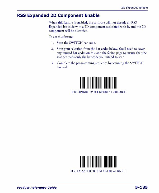
RSS Expanded Enable
Product Reference Guide 5-185
RSS Expanded 2D Component EnableWhen this feature is enabled, the software will not decode an RSS Expanded bar code with a 2D component associated with it, and the 2D component will be discarded.
To set this feature:
1. Scan the SWITCH bar code.
2. Scan your selection from the bar codes below. You’ll need to cover any unused bar codes on this and the facing page to ensure that the scanner reads only the bar code you intend to scan.
3. Complete the programming sequence by scanning the SWITCH bar code.
RSS EXPANDED 2D COMPONENT = DISABLE
RSS EXPANDED 2D COMPONENT = ENABLE
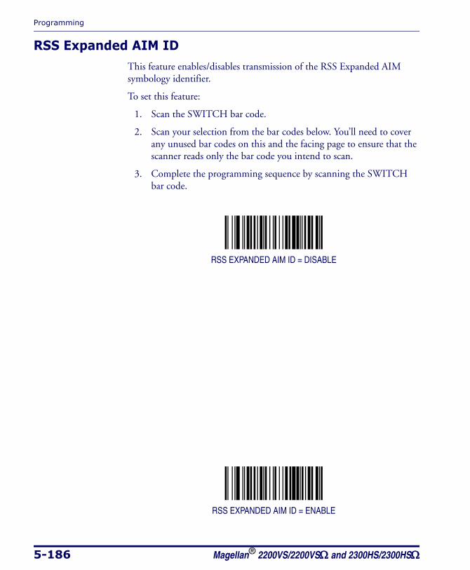
Programming
5-186 Magellan® 2200VS/2200VSΩ and 2300HS/2300HSΩ
RSS Expanded AIM IDThis feature enables/disables transmission of the RSS Expanded AIM symbology identifier.
To set this feature:
1. Scan the SWITCH bar code.
2. Scan your selection from the bar codes below. You’ll need to cover any unused bar codes on this and the facing page to ensure that the scanner reads only the bar code you intend to scan.
3. Complete the programming sequence by scanning the SWITCH bar code.
RSS EXPANDED AIM ID = DISABLE
RSS EXPANDED AIM ID = ENABLE
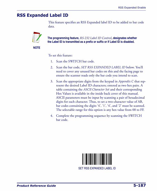
RSS Expanded Enable
Product Reference Guide 5-187
RSS Expanded Label IDThis feature specifies an RSS Expanded label ID to be added to bar code data.
To set this feature:
1. Scan the SWITCH bar code.
2. Scan the bar code, SET RSS EXPANDED LABEL ID below. You’ll need to cover any unused bar codes on this and the facing page to ensure the scanner reads only the bar code you intend to scan.
3. Scan the appropriate digits from the keypad in Appendix C that rep-resent the desired Label ID characters; entered as two hex pairs. A table containing the ASCII Character Set and their corresponding Hex Values is available in the inside back cover of this manual. ASCII parameters must be input by scanning a pair of hexadecimal digits for each character. Thus, to set a two-character value of AB, bar codes containing the digits ‘4’, ‘1’, ‘4’, and ‘2’ must be scanned. The selectable range for this option is any hex value from 00 to FF.
4. Complete the programming sequence by scanning the SWITCH bar code.
SET RSS EXPANDED LABEL ID
NOTE
The programming feature, RS-232 Label ID Control, designates whether the Label ID is transmitted as a prefix or suffix or if Label ID is disabled.
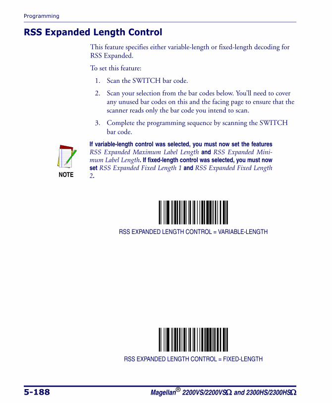
Programming
5-188 Magellan® 2200VS/2200VSΩ and 2300HS/2300HSΩ
RSS Expanded Length ControlThis feature specifies either variable-length or fixed-length decoding for RSS Expanded.
To set this feature:
1. Scan the SWITCH bar code.
2. Scan your selection from the bar codes below. You’ll need to cover any unused bar codes on this and the facing page to ensure that the scanner reads only the bar code you intend to scan.
3. Complete the programming sequence by scanning the SWITCH bar code.
RSS EXPANDED LENGTH CONTROL = VARIABLE-LENGTH
RSS EXPANDED LENGTH CONTROL = FIXED-LENGTH
NOTE
If variable-length control was selected, you must now set the features RSS Expanded Maximum Label Length and RSS Expanded Mini-mum Label Length. If fixed-length control was selected, you must now set RSS Expanded Fixed Length 1 and RSS Expanded Fixed Length 2.
RSS Expanded Enable
Product Reference Guide 5-189
RSS Expanded Maximum Label LengthThis feature specifies the maximum allowable length of an RSS Expanded label.
To set this feature:
1. Scan the SWITCH bar code.
2. Scan the bar code, SET RSS EXPANDED MAXIMUM LABEL LENGTH below. You’ll need to cover any unused bar codes on this and the facing page to ensure that the scanner reads only the bar code you intend to scan.
3. Scan the appropriate digits from the keypad in Appendix C that rep-resent the desired maximum label length. The selectable range for this option is 00 to 74. Pad all single digit numbers with a leading zero to yield a two-digit entry (00-74).
4. Complete the programming sequence by scanning the SWITCH bar code.
SET RSS EXPANDED MAXIMUM LABEL LENGTH
NOTE
Length in this case includes check and data characters. This applies when RSS Expanded Length Control is set to variable-length decod-ing.
Maximum Label Length should be greater than or equal to Minimum Label Length.
Programming
5-190 Magellan® 2200VS/2200VSΩ and 2300HS/2300HSΩ
RSS Expanded Minimum Label LengthThis feature specifies the minimum allowable length of an RSS Expanded label.
To set this feature:
1. Scan the SWITCH bar code.
2. Scan the bar code, SET RSS EXPANDED MINIMUM LABEL LENGTH below. You’ll need to cover any unused bar codes on this and the facing page to ensure that the scanner reads only the bar code you intend to scan.
3. Scan the appropriate digits from the keypad in Appendix C that rep-resent the desired minimum label length. The selectable range for this option is 00 to 74. Pad all single digit numbers with a leading zero to yield a two-digit entry (00-74).
4. Complete the programming sequence by scanning the SWITCH bar code.
SET RSS EXPANDED MINIMUM LABEL LENGTH
NOTE
Length in this case includes check and data characters. This applies when RSS Expanded Length Control is set to variable-length decoding.
Minimum Label Length should be less than or equal to Maximum Label Length.

RSS Expanded Enable
Product Reference Guide 5-191
RSS Expanded Fixed Length 1This feature specifies RSS Expanded first fixed length.
To set this feature:
1. Scan the SWITCH bar code.
2. Scan the bar code, SET RSS EXPANDED FIXED LENGTH 1 below. You’ll need to cover any unused bar codes on this and the facing page to ensure that the scanner reads only the bar code you intend to scan.
3. Scan the appropriate digits from the keypad in Appendix C that rep-resent the desired fixed label length. The selectable range for this option is 00 to 74. Pad all single digit numbers with a leading zero to yield a two-digit entry (00-74).
4. Complete the programming sequence by scanning the SWITCH bar code.
SET RSS EXPANDED FIXED LENGTH 1
NOTE
This applies when RSS Expanded Length Control is set to fixed-length decoding.
Programming
5-192 Magellan® 2200VS/2200VSΩ and 2300HS/2300HSΩ
RSS Expanded Fixed Length 2This feature specifies RSS Expanded second fixed length.
To set this feature:
1. Scan the SWITCH bar code.
2. Scan the bar code, SET RSS EXPANDED FIXED LENGTH 2 below. You’ll need to cover any unused bar codes on this and the facing page to ensure that the scanner reads only the bar code you intend to scan.
3. Scan the appropriate digits from the keypad in Appendix C that rep-resent the desired fixed label length. The selectable range for this option is 00 to 74. Pad all single digit numbers with a leading zero to yield a two-digit entry (00-74).
4. Complete the programming sequence by scanning the SWITCH bar code.
SET RSS EXPANDED FIXED LENGTH 2
NOTE
This applies when RSS Expanded Length Control is set to fixed-length decoding.
If Fixed Length 2 is set to 00 (zero), then Fixed Length 1 will apply.
Code 39 Enable
Product Reference Guide 5-193
Code 39 EnableEnables/disables the ability of the scanner to decode Code 39 labels.
To set this feature:
1. Scan the SWITCH bar code.
2. Scan either the enable or disable bar code below. You’ll need to cover any unused bar codes on this and the facing page to ensure that the scanner reads only the bar code you intend to scan.
3. Complete the programming sequence by scanning the SWITCH bar code.
CODE 39 = DISABLE
CODE 39 = ENABLE
Programming
5-194 Magellan® 2200VS/2200VSΩ and 2300HS/2300HSΩ
Code 39 Start Stop Character TransmissionEnables/disables transmission of Code 39 start and stop characters.
To set this feature:
1. Scan the SWITCH bar code.
2. Scan either the enable or disable bar code below. You’ll need to cover any unused bar codes on this and the facing page to ensure that the scanner reads only the bar code you intend to scan.
3. Complete the programming sequence by scanning the SWITCH bar code.
CODE 39 START STOP CHARACTER TRANSMISSION = DISABLE
CODE 39 START STOP CHARACTER TRANSMISSION = ENABLE
NOTE
This item is ignored when the advanced feature, Full Label Edit, is enabled.
Code 39 Enable
Product Reference Guide 5-195
Code 39 Check Character CalculationEnables/disables calculation and verification of an optional Code 39 check character. When disabled, any check character in label is treated as a data character.
To set this feature:
1. Scan the SWITCH bar code.
2. Scan either the enable or disable bar code below. You’ll need to cover any unused bar codes on this and the facing page to ensure that the scanner reads only the bar code you intend to scan.
3. Complete the programming sequence by scanning the SWITCH bar code.
CODE 39 CHECK CHARACTER CALCULATION = DISABLE
CODE 39 CHECK CHARACTER CALCULATION = ENABLE
NOTE
If check calculation is disabled, the risk is increased that a misread can occur.
Programming
5-196 Magellan® 2200VS/2200VSΩ and 2300HS/2300HSΩ
Code 39 Check Character TransmissionEnables/disables transmission of optional Code 39 check character.
To set this feature:
1. Scan the SWITCH bar code.
2. Scan either the enable or disable bar code below. You’ll need to cover any unused bar codes on this and the facing page to ensure that the scanner reads only the bar code you intend to scan.
3. Complete the programming sequence by scanning the SWITCH bar code.
CODE 39 CHECK CHARACTER TRANSMISSION = DISABLE
CODE 39 CHECK CHARACTER TRANSMISSION = ENABLE
NOTE
This item is ignored when the advanced feature, Full Label Edit, is enabled.
Code 39 Enable
Product Reference Guide 5-197
Code 39 Full ASCIIEnables/disables the ability of the scanner to translate to Code 39 full ASCII labels.
To set this feature:
1. Scan the SWITCH bar code.
2. Scan either the enable or disable bar code below. You’ll need to cover any unused bar codes on this and the facing page to ensure that the scanner reads only the bar code you intend to scan.
3. Complete the programming sequence by scanning the SWITCH bar code.
CODE 39 FULL ASCII = DISABLE
CODE 39 FULL ASCII = ENABLE
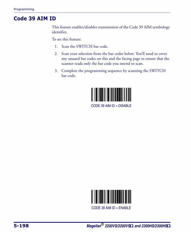
Programming
5-198 Magellan® 2200VS/2200VSΩ and 2300HS/2300HSΩ
Code 39 AIM IDThis feature enables/disables transmission of the Code 39 AIM symbology identifier.
To set this feature:
1. Scan the SWITCH bar code.
2. Scan your selection from the bar codes below. You’ll need to cover any unused bar codes on this and the facing page to ensure that the scanner reads only the bar code you intend to scan.
3. Complete the programming sequence by scanning the SWITCH bar code.
CODE 39 AIM ID = DISABLE
CODE 39 AIM ID = ENABLE
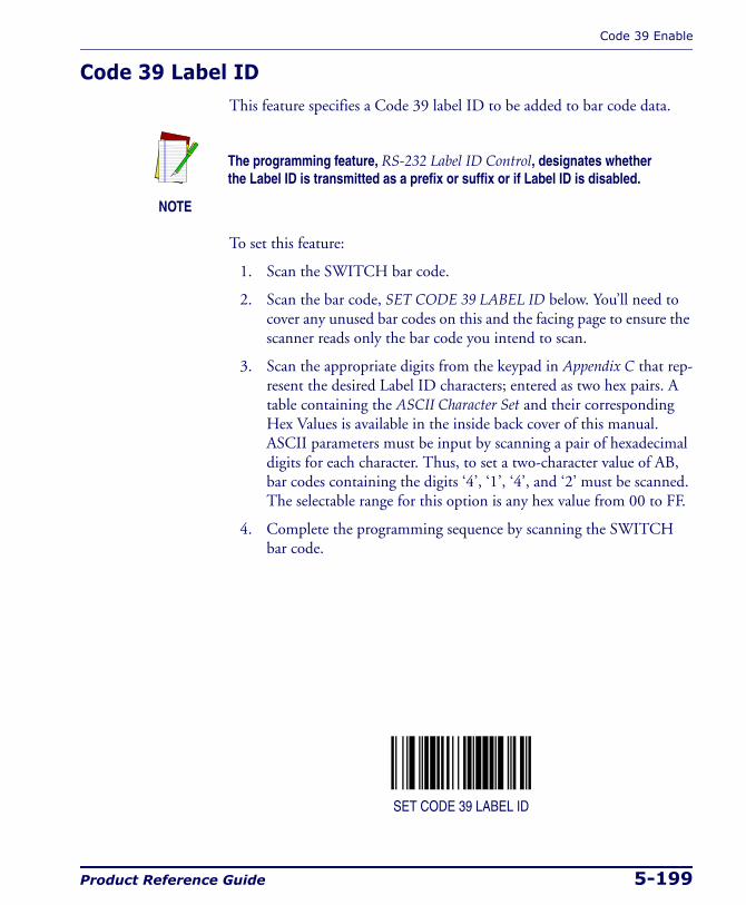
Code 39 Enable
Product Reference Guide 5-199
Code 39 Label IDThis feature specifies a Code 39 label ID to be added to bar code data.
To set this feature:
1. Scan the SWITCH bar code.
2. Scan the bar code, SET CODE 39 LABEL ID below. You’ll need to cover any unused bar codes on this and the facing page to ensure the scanner reads only the bar code you intend to scan.
3. Scan the appropriate digits from the keypad in Appendix C that rep-resent the desired Label ID characters; entered as two hex pairs. A table containing the ASCII Character Set and their corresponding Hex Values is available in the inside back cover of this manual. ASCII parameters must be input by scanning a pair of hexadecimal digits for each character. Thus, to set a two-character value of AB, bar codes containing the digits ‘4’, ‘1’, ‘4’, and ‘2’ must be scanned. The selectable range for this option is any hex value from 00 to FF.
4. Complete the programming sequence by scanning the SWITCH bar code.
SET CODE 39 LABEL ID
NOTE
The programming feature, RS-232 Label ID Control, designates whether the Label ID is transmitted as a prefix or suffix or if Label ID is disabled.
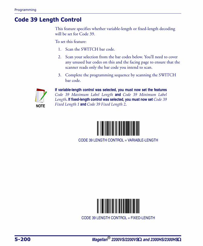
Programming
5-200 Magellan® 2200VS/2200VSΩ and 2300HS/2300HSΩ
Code 39 Length ControlThis feature specifies whether variable-length or fixed-length decoding will be set for Code 39.
To set this feature:
1. Scan the SWITCH bar code.
2. Scan your selection from the bar codes below. You’ll need to cover any unused bar codes on this and the facing page to ensure that the scanner reads only the bar code you intend to scan.
3. Complete the programming sequence by scanning the SWITCH bar code.
CODE 39 LENGTH CONTROL = VARIABLE-LENGTH
CODE 39 LENGTH CONTROL = FIXED-LENGTH
NOTE
If variable-length control was selected, you must now set the features Code 39 Maximum Label Length and Code 39 Minimum Label Length. If fixed-length control was selected, you must now set Code 39 Fixed Length 1 and Code 39 Fixed Length 2.
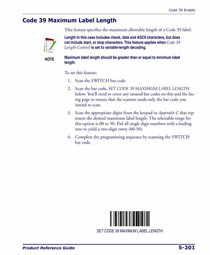
Code 39 Enable
Product Reference Guide 5-201
Code 39 Maximum Label LengthThis feature specifies the maximum allowable length of a Code 39 label.
To set this feature:
1. Scan the SWITCH bar code.
2. Scan the bar code, SET CODE 39 MAXIMUM LABEL LENGTH below. You’ll need to cover any unused bar codes on this and the fac-ing page to ensure that the scanner reads only the bar code you intend to scan.
3. Scan the appropriate digits from the keypad in Appendix C that rep-resent the desired maximum label length. The selectable range for this option is 00 to 50. Pad all single digit numbers with a leading zero to yield a two-digit entry (00-50).
4. Complete the programming sequence by scanning the SWITCH bar code.
SET CODE 39 MAXIMUM LABEL LENGTH
NOTE
Length in this case includes check, data and ASCII characters, but does not include start, or stop characters. This feature applies when Code 39 Length Control is set to variable-length decoding.
Maximum label length should be greater than or equal to minimum label length.
Programming
5-202 Magellan® 2200VS/2200VSΩ and 2300HS/2300HSΩ
Code 39 Minimum Label LengthThis feature specifies the minimum allowable length of a Code 39 label.
To set this feature:
1. Scan the SWITCH bar code.
2. Scan the bar code, SET CODE 39 MINIMUM LABEL LENGTH below. You’ll need to cover any unused bar codes on this and the fac-ing page to ensure that the scanner reads only the bar code you intend to scan.
3. Scan the appropriate digits from the keypad in Appendix C that rep-resent the desired minimum label length. The selectable range for this option is 00 to 50. Pad all single digit numbers with a leading zero to yield a two-digit entry (00-50).
4. Complete the programming sequence by scanning the SWITCH bar code.
SET CODE 39 MINIMUM LABEL LENGTH
NOTE
Length in this case includes check, data and ASCII characters, but does not include start, or stop characters. This feature applies when Code 39 Length Control is set to variable-length decoding.
Minimum label length should be less than or equal to maximum label length.
Code 39 Enable
Product Reference Guide 5-203
Code 39 Fixed Length 1This feature specifies Code 39 first fixed length.
To set this feature:
1. Scan the SWITCH bar code.
2. Scan the bar code, SET CODE 39 FIXED LENGTH 1 below. You’ll need to cover any unused bar codes on this and the facing page to ensure that the scanner reads only the bar code you intend to scan.
3. Scan the appropriate digits from the keypad in Appendix C that rep-resent the desired fixed label length. The selectable range for this option is 00 to 50. Pad all single digit numbers with a leading zero to yield a two-digit entry (00-50).
4. Complete the programming sequence by scanning the SWITCH bar code.
SET CODE 39 FIXED LENGTH 1
NOTE
This applies when Code 39 Length Control is set to fixed-length decoding.
The minimum decodable length is four when an optional check charac-ter is present.

Programming
5-204 Magellan® 2200VS/2200VSΩ and 2300HS/2300HSΩ
Code 39 Fixed Length 2This feature specifies Code 39 second fixed length.
To set this feature:
1. Scan the SWITCH bar code.
2. Scan the bar code, SET CODE 39 FIXED LENGTH 2 below. You’ll need to cover any unused bar codes on this and the facing page to ensure that the scanner reads only the bar code you intend to scan.
3. Scan the appropriate digits from the keypad in Appendix C that rep-resent the desired fixed label length. The selectable range for this option is 00, no second fixed length, or 01 to 50. Pad all single digit numbers with a leading zero to yield a two-digit entry (00-50).
4. Complete the programming sequence by scanning the SWITCH bar code.
SET CODE 39 FIXED LENGTH 2
NOTE
This applies when Code 39 Length Control is set to fixed-length decoding.
If Fixed Length 2 is set to 00, then Fixed Length 1 will apply
Code 39 Enable
Product Reference Guide 5-205
Code 39 StitchingEnables/disables stitching for Code 39 labels. When parts of a Code 39 bar code are presented to the scanner with this feature enabled, the bar code parts will be assembled by the scanner’s software, and the data will be decoded if all bar code proofing requirements are met.
To set this feature:
1. Scan the SWITCH bar code.
2. Scan your selection from the bar codes below. You’ll need to cover any unused bar codes on this and the facing page to ensure that the scanner reads only the bar code you intend to scan.
Complete the programming sequence by scanning the SWITCH bar code.
CODE 39 STITCHING = DISABLE
CODE 39 STITCHING = ENABLE
Programming
5-206 Magellan® 2200VS/2200VSΩ and 2300HS/2300HSΩ
Pharmacode 39 EnableEnables/disables the ability of the scanner to decode Italian Pharmacode 39 labels.
To set this feature:
1. Scan the SWITCH bar code.
2. Scan either the enable or disable bar code below. You’ll need to cover any unused bar codes on this and the facing page to ensure that the scanner reads only the bar code you intend to scan.
3. Complete the programming sequence by scanning the SWITCH bar code.
PHARMACODE 39 = DISABLE
PHARMACODE 39 = ENABLE
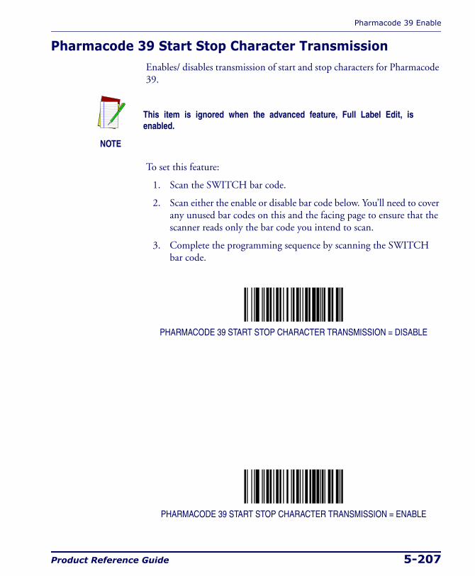
Pharmacode 39 Enable
Product Reference Guide 5-207
Pharmacode 39 Start Stop Character TransmissionEnables/ disables transmission of start and stop characters for Pharmacode 39.
To set this feature:
1. Scan the SWITCH bar code.
2. Scan either the enable or disable bar code below. You’ll need to cover any unused bar codes on this and the facing page to ensure that the scanner reads only the bar code you intend to scan.
3. Complete the programming sequence by scanning the SWITCH bar code.
PHARMACODE 39 START STOP CHARACTER TRANSMISSION = DISABLE
PHARMACODE 39 START STOP CHARACTER TRANSMISSION = ENABLE
NOTE
This item is ignored when the advanced feature, Full Label Edit, is enabled.
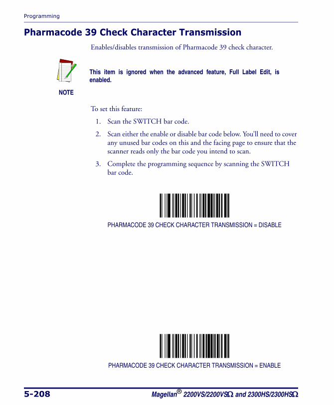
Programming
5-208 Magellan® 2200VS/2200VSΩ and 2300HS/2300HSΩ
Pharmacode 39 Check Character TransmissionEnables/disables transmission of Pharmacode 39 check character.
To set this feature:
1. Scan the SWITCH bar code.
2. Scan either the enable or disable bar code below. You’ll need to cover any unused bar codes on this and the facing page to ensure that the scanner reads only the bar code you intend to scan.
3. Complete the programming sequence by scanning the SWITCH bar code.
PHARMACODE 39 CHECK CHARACTER TRANSMISSION = DISABLE
PHARMACODE 39 CHECK CHARACTER TRANSMISSION = ENABLE
NOTE
This item is ignored when the advanced feature, Full Label Edit, is enabled.
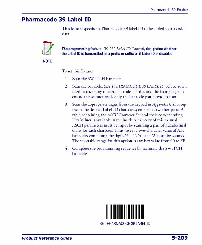
Pharmacode 39 Enable
Product Reference Guide 5-209
Pharmacode 39 Label IDThis feature specifies a Pharmacode 39 label ID to be added to bar code data.
To set this feature:
1. Scan the SWITCH bar code.
2. Scan the bar code, SET PHARMACODE 39 LABEL ID below. You’ll need to cover any unused bar codes on this and the facing page to ensure the scanner reads only the bar code you intend to scan.
3. Scan the appropriate digits from the keypad in Appendix C that rep-resent the desired Label ID characters; entered as two hex pairs. A table containing the ASCII Character Set and their corresponding Hex Values is available in the inside back cover of this manual. ASCII parameters must be input by scanning a pair of hexadecimal digits for each character. Thus, to set a two-character value of AB, bar codes containing the digits ‘4’, ‘1’, ‘4’, and ‘2’ must be scanned. The selectable range for this option is any hex value from 00 to FF.
4. Complete the programming sequence by scanning the SWITCH bar code.
SET PHARMACODE 39 LABEL ID
NOTE
The programming feature, RS-232 Label ID Control, designates whether the Label ID is transmitted as a prefix or suffix or if Label ID is disabled.
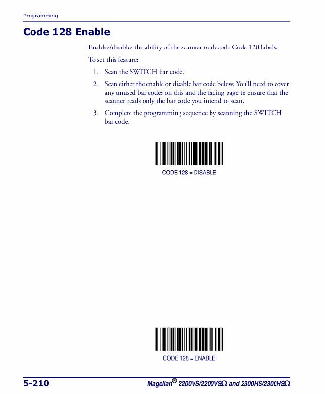
Programming
5-210 Magellan® 2200VS/2200VSΩ and 2300HS/2300HSΩ
Code 128 EnableEnables/disables the ability of the scanner to decode Code 128 labels.
To set this feature:
1. Scan the SWITCH bar code.
2. Scan either the enable or disable bar code below. You’ll need to cover any unused bar codes on this and the facing page to ensure that the scanner reads only the bar code you intend to scan.
3. Complete the programming sequence by scanning the SWITCH bar code.
CODE 128 = DISABLE
CODE 128 = ENABLE
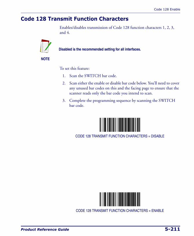
Code 128 Enable
Product Reference Guide 5-211
Code 128 Transmit Function CharactersEnables/disables transmission of Code 128 function characters 1, 2, 3, and 4.
To set this feature:
1. Scan the SWITCH bar code.
2. Scan either the enable or disable bar code below. You’ll need to cover any unused bar codes on this and the facing page to ensure that the scanner reads only the bar code you intend to scan.
3. Complete the programming sequence by scanning the SWITCH bar code.
CODE 128 TRANSMIT FUNCTION CHARACTERS = DISABLE
CODE 128 TRANSMIT FUNCTION CHARACTERS = ENABLE
NOTE
Disabled is the recommended setting for all interfaces.
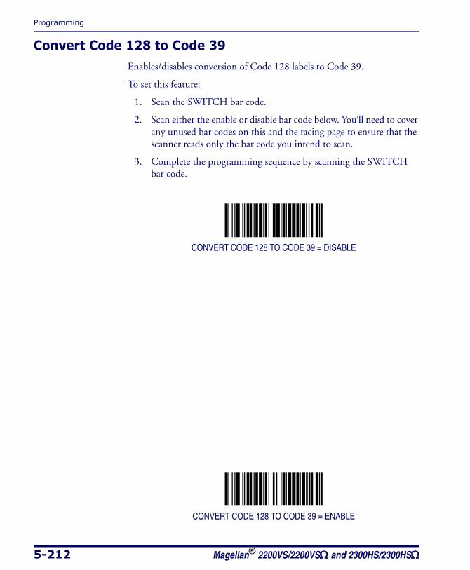
Programming
5-212 Magellan® 2200VS/2200VSΩ and 2300HS/2300HSΩ
Convert Code 128 to Code 39Enables/disables conversion of Code 128 labels to Code 39.
To set this feature:
1. Scan the SWITCH bar code.
2. Scan either the enable or disable bar code below. You’ll need to cover any unused bar codes on this and the facing page to ensure that the scanner reads only the bar code you intend to scan.
3. Complete the programming sequence by scanning the SWITCH bar code.
CONVERT CODE 128 TO CODE 39 = DISABLE
CONVERT CODE 128 TO CODE 39 = ENABLE
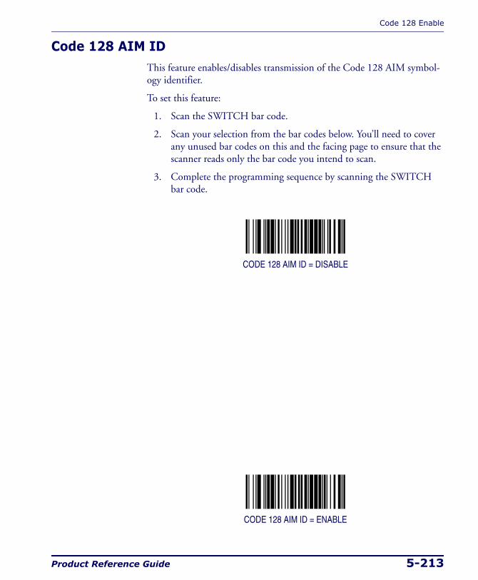
Code 128 Enable
Product Reference Guide 5-213
Code 128 AIM IDThis feature enables/disables transmission of the Code 128 AIM symbol-ogy identifier.
To set this feature:
1. Scan the SWITCH bar code.
2. Scan your selection from the bar codes below. You’ll need to cover any unused bar codes on this and the facing page to ensure that the scanner reads only the bar code you intend to scan.
3. Complete the programming sequence by scanning the SWITCH bar code.
CODE 128 AIM ID = DISABLE
CODE 128 AIM ID = ENABLE

Programming
5-214 Magellan® 2200VS/2200VSΩ and 2300HS/2300HSΩ
Code 128 Label IDThis feature specifies a Code 128 label ID to be added to bar code data.
To set this feature:
1. Scan the SWITCH bar code.
2. Scan the bar code, SET CODE 128 LABEL ID below. You’ll need to cover any unused bar codes on this and the facing page to ensure the scanner reads only the bar code you intend to scan.
3. Scan the appropriate digits from the keypad in Appendix C that rep-resent the desired Label ID characters; entered as two hex pairs. A table containing the ASCII Character Set and their corresponding Hex Values is available in the inside back cover of this manual. ASCII parameters must be input by scanning a pair of hexadecimal digits for each character. Thus, to set a two-character value of AB, bar codes containing the digits ‘4’, ‘1’, ‘4’, and ‘2’ must be scanned. The selectable range for this option is any hex value from 00 to FF.
4. Complete the programming sequence by scanning the SWITCH bar code.
SET CODE 128 LABEL ID
NOTE
The programming feature, RS-232 Label ID Control, designates whether the Label ID is transmitted as a prefix or suffix or if Label ID is disabled.
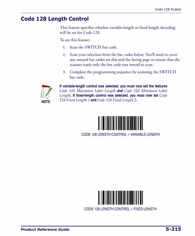
Code 128 Enable
Product Reference Guide 5-215
Code 128 Length ControlThis feature specifies whether variable-length or fixed-length decoding will be set for Code 128.
To set this feature:
1. Scan the SWITCH bar code.
2. Scan your selection from the bar codes below. You’ll need to cover any unused bar codes on this and the facing page to ensure that the scanner reads only the bar code you intend to scan.
3. Complete the programming sequence by scanning the SWITCH bar code.
CODE 128 LENGTH CONTROL = VARIABLE-LENGTH
CODE 128 LENGTH CONTROL = FIXED-LENGTH
NOTE
If variable-length control was selected, you must now set the features Code 128 Maximum Label Length and Code 128 Minimum Label Length. If fixed-length control was selected, you must now set Code 128 Fixed Length 1 and Code 128 Fixed Length 2.
Programming
5-216 Magellan® 2200VS/2200VSΩ and 2300HS/2300HSΩ
Code 128 Maximum Label LengthThis feature specifies the maximum allowable length of a Code 128 label.
To set this feature:
1. Scan the SWITCH bar code.
2. Scan the bar code, SET CODE 128 MAXIMUM LABEL LENGTH below. You’ll need to cover any unused bar codes on this and the fac-ing page to ensure that the scanner reads only the bar code you intend to scan.
3. Scan the appropriate digits from the keypad in Appendix C that rep-resent the desired maximum label length. The selectable range for this option is 01 to 80. Pad all single digit numbers with a leading zero to yield a two-digit entry (01-80).
4. Complete the programming sequence by scanning the SWITCH bar code.
SET CODE 128 MAXIMUM LABEL LENGTH
NOTE
Length in this case includes function characters and data charac-ters, but does not include function code change or check character. This feature applies when Code 128 Length Control is set to vari-able-length decoding.
Maximum label length should be greater than or equal to minimum label length.
Code 128 Enable
Product Reference Guide 5-217
Code 128 Minimum Label LengthThis feature specifies the minimum allowable length of a Code 128 label.
To set this feature:
1. Scan the SWITCH bar code.
2. Scan the bar code, SET CODE 128 MINIMUM LABEL LENGTH below. You’ll need to cover any unused bar codes on this and the fac-ing page to ensure that the scanner reads only the bar code you intend to scan.
3. Scan the appropriate digits from the keypad in Appendix C that rep-resent the desired minimum label length. The selectable range for this option is 01 to 80. Pad all single digit numbers with a leading zero to yield a two-digit entry (01-80).
4. Complete the programming sequence by scanning the SWITCH bar code.
SET CODE 128 MINIMUM LABEL LENGTH
NOTE
Length in this case includes function characters and data characters, but does not include function code change or check character. This fea-ture applies when Code 128 Length Control is set to variable-length decoding.
Minimum label length should be less than or equal to maximum label length.

Programming
5-218 Magellan® 2200VS/2200VSΩ and 2300HS/2300HSΩ
Code 128 Fixed Length 1This feature specifies Code 128 first fixed length.
To set this feature:
1. Scan the SWITCH bar code.
2. Scan the bar code, SET CODE 128 FIXED LENGTH 1 below. You’ll need to cover any unused bar codes on this and the facing page to ensure that the scanner reads only the bar code you intend to scan.
3. Scan the appropriate digits from the keypad in Appendix C that rep-resent the desired fixed label length. The selectable range for this option is 01 to 80. Pad all single digit numbers with a leading zero to yield a two-digit entry (01-80).
4. Complete the programming sequence by scanning the SWITCH bar code.
SET CODE 128 FIXED LENGTH 1
NOTE
This applies when Code 128 Length Control is set to fixed-length decoding.
Code 128 Enable
Product Reference Guide 5-219
Code 128 Fixed Length 2This feature specifies Code 128 second fixed length.
To set this feature:
1. Scan the SWITCH bar code.
2. Scan the bar code, SET CODE 128 FIXED LENGTH 2 below. You’ll need to cover any unused bar codes on this and the facing page to ensure that the scanner reads only the bar code you intend to scan.
3. Scan the appropriate digits from the keypad in Appendix C that rep-resent the desired fixed label length. The selectable range for this option is 01 to 80. Pad all single digit numbers with a leading zero to yield a two-digit entry (01-80).
4. Complete the programming sequence by scanning the SWITCH bar code.
SET CODE 128 FIXED LENGTH 2
NOTE
This applies when Code 128 Length Control is set to fixed-length decoding.
If Fixed Length 2 is set to 00 (zero), then Fixed Length 1 will apply.
Programming
5-220 Magellan® 2200VS/2200VSΩ and 2300HS/2300HSΩ
Code 128 StitchingEnables/disables stitching for Code 128 labels. When parts of a Code 128 bar code are presented to the scanner with this feature enabled, the bar code parts will be assembled by the scanner’s software, and the data will be decoded if all bar code proofing requirements are met.
To set this feature:
1. Scan the SWITCH bar code.
2. Scan your selection from the bar codes below. You’ll need to cover any unused bar codes on this and the facing page to ensure that the scanner reads only the bar code you intend to scan.
Complete the programming sequence by scanning the SWITCH bar code.
CODE 128 STITCHING = DISABLE
CODE 128 STITCHING = ENABLE

EAN-128 Enable
Product Reference Guide 5-221
EAN-128 EnableEnables/disables the ability of the scanner to decode EAN-128 labels.
To set this feature:
1. Scan the SWITCH bar code.
2. Scan either the enable or disable bar code below. You’ll need to cover any unused bar codes on this and the facing page to ensure that the scanner reads only the bar code you intend to scan.
3. Complete the programming sequence by scanning the SWITCH bar code.
EAN-128 = DISABLE
EAN-128 = ENABLE

Programming
5-222 Magellan® 2200VS/2200VSΩ and 2300HS/2300HSΩ
EAN 128 AIM IDThis feature enables/disables transmission of the EAN 128 AIM symbol-ogy identifier.
To set this feature:
1. Scan the SWITCH bar code.
2. Scan your selection from the bar codes below. You’ll need to cover any unused bar codes on this and the facing page to ensure that the scanner reads only the bar code you intend to scan.
3. Complete the programming sequence by scanning the SWITCH bar code.
EAN 128 AIM ID = DISABLE
EAN 128 AIM ID = ENABLE
EAN-128 Enable
Product Reference Guide 5-223
EAN 128 Label IDThis feature specifies an EAN 128 label ID to be added to bar code data.
To set this feature:
1. Scan the SWITCH bar code.
2. Scan the bar code, SET EAN 128 LABEL ID below. You’ll need to cover any unused bar codes on this and the facing page to ensure the scanner reads only the bar code you intend to scan.
3. Scan the appropriate digits from the keypad in Appendix C that rep-resent the desired Label ID characters; entered as two hex pairs. A table containing the ASCII Character Set and their corresponding Hex Values is available in the inside back cover of this manual. ASCII parameters must be input by scanning a pair of hexadecimal digits for each character. Thus, to set a two-character value of AB, bar codes containing the digits ‘4’, ‘1’, ‘4’, and ‘2’ must be scanned. The selectable range for this option is any hex value from 00 to FF.
4. Complete the programming sequence by scanning the SWITCH bar code.
SET EAN 128 LABEL ID
NOTE
The programming feature, RS-232 Label ID Control, designates whether the Label ID is transmitted as a prefix or suffix or if Label ID is disabled.
Programming
5-224 Magellan® 2200VS/2200VSΩ and 2300HS/2300HSΩ
Interleaved 2 of 5 (I 2 OF 5) EnableEnables/disables the ability of the scanner to decode Interleaved 2 of 5 labels.
To set this feature:
1. Scan the SWITCH bar code.
2. Scan either the enable or disable bar code below. You’ll need to cover any unused bar codes on this and the facing page to ensure that the scanner reads only the bar code you intend to scan.
3. Complete the programming sequence by scanning the SWITCH bar code.
I 2 OF 5 = DISABLE
I 2 OF 5 = ENABLE
Interleaved 2 of 5 (I 2 OF 5) Enable
Product Reference Guide 5-225
I 2 of 5 Check Character CalculationEnables/disables calculation and verification of an optional Interleaved 2 of 5 check character.
To set this feature:
1. Scan the SWITCH bar code.
2. Scan either the enable or disable bar code below. You’ll need to cover any unused bar codes on this and the facing page to ensure that the scanner reads only the bar code you intend to scan.
3. Complete the programming sequence by scanning the SWITCH bar code.
I 2 of 5 CHECK CHARACTER CALCULATION = DISABLE
I 2 of 5 CHECK CHARACTER CALCULATION = ENABLE
NOTE
If check character calculation is disabled, the risk is increased that a mis-read can occur. When disabled, any check characters in a bar code are treated as data characters.
Programming
5-226 Magellan® 2200VS/2200VSΩ and 2300HS/2300HSΩ
I 2 of 5 Check Character TransmissionEnables/disables transmission of an optional Interleaved 2 of 5 check char-acter.
To set this feature:
1. Scan the SWITCH bar code.
2. Scan either the enable or disable bar code below. You’ll need to cover any unused bar codes on this and the facing page to ensure that the scanner reads only the bar code you intend to scan.
3. Complete the programming sequence by scanning the SWITCH bar code.
I 2 of 5 CHECK CHARACTER TRANSMISSION = DISABLE
I 2 of 5 CHECK CHARACTER TRANSMISSION = ENABLE
NOTE
This feature applies only when I 2 of 5 Check Character Calculationis enabled. This item is ignored when the advanced feature, Full Label Edit, is enabled.
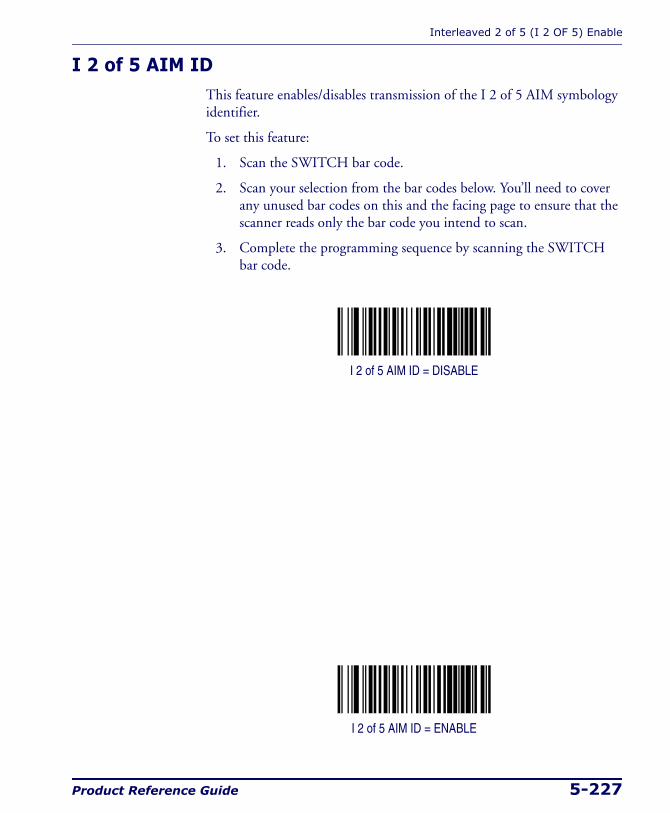
Interleaved 2 of 5 (I 2 OF 5) Enable
Product Reference Guide 5-227
I 2 of 5 AIM IDThis feature enables/disables transmission of the I 2 of 5 AIM symbology identifier.
To set this feature:
1. Scan the SWITCH bar code.
2. Scan your selection from the bar codes below. You’ll need to cover any unused bar codes on this and the facing page to ensure that the scanner reads only the bar code you intend to scan.
3. Complete the programming sequence by scanning the SWITCH bar code.
I 2 of 5 AIM ID = DISABLE
I 2 of 5 AIM ID = ENABLE
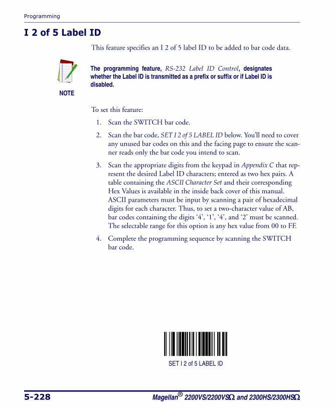
Programming
5-228 Magellan® 2200VS/2200VSΩ and 2300HS/2300HSΩ
I 2 of 5 Label IDThis feature specifies an I 2 of 5 label ID to be added to bar code data.
To set this feature:
1. Scan the SWITCH bar code.
2. Scan the bar code, SET I 2 of 5 LABEL ID below. You’ll need to cover any unused bar codes on this and the facing page to ensure the scan-ner reads only the bar code you intend to scan.
3. Scan the appropriate digits from the keypad in Appendix C that rep-resent the desired Label ID characters; entered as two hex pairs. A table containing the ASCII Character Set and their corresponding Hex Values is available in the inside back cover of this manual. ASCII parameters must be input by scanning a pair of hexadecimal digits for each character. Thus, to set a two-character value of AB, bar codes containing the digits ‘4’, ‘1’, ‘4’, and ‘2’ must be scanned. The selectable range for this option is any hex value from 00 to FF.
4. Complete the programming sequence by scanning the SWITCH bar code.
SET I 2 of 5 LABEL ID
NOTE
The programming feature, RS-232 Label ID Control, designates whether the Label ID is transmitted as a prefix or suffix or if Label ID is disabled.
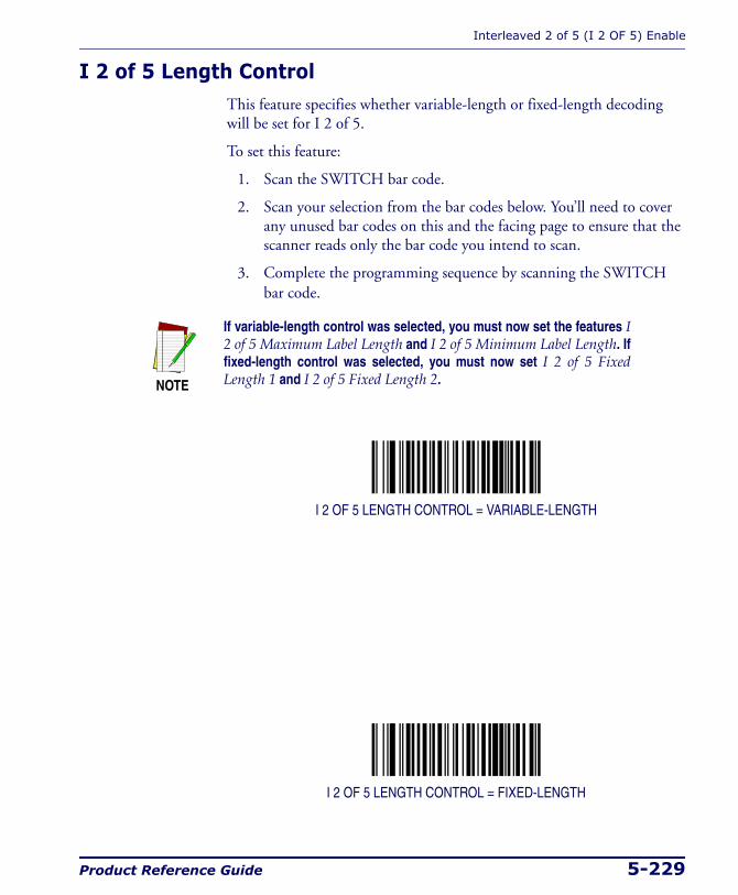
Interleaved 2 of 5 (I 2 OF 5) Enable
Product Reference Guide 5-229
I 2 of 5 Length ControlThis feature specifies whether variable-length or fixed-length decoding will be set for I 2 of 5.
To set this feature:
1. Scan the SWITCH bar code.
2. Scan your selection from the bar codes below. You’ll need to cover any unused bar codes on this and the facing page to ensure that the scanner reads only the bar code you intend to scan.
3. Complete the programming sequence by scanning the SWITCH bar code.
I 2 OF 5 LENGTH CONTROL = VARIABLE-LENGTH
I 2 OF 5 LENGTH CONTROL = FIXED-LENGTH
NOTE
If variable-length control was selected, you must now set the features I 2 of 5 Maximum Label Length and I 2 of 5 Minimum Label Length. If fixed-length control was selected, you must now set I 2 of 5 Fixed Length 1 and I 2 of 5 Fixed Length 2.
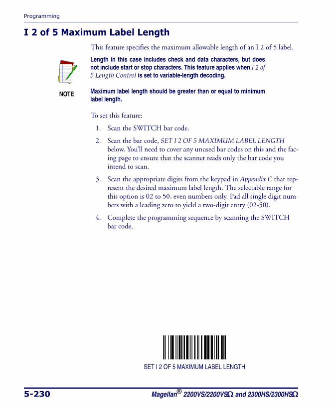
Programming
5-230 Magellan® 2200VS/2200VSΩ and 2300HS/2300HSΩ
I 2 of 5 Maximum Label LengthThis feature specifies the maximum allowable length of an I 2 of 5 label.
To set this feature:
1. Scan the SWITCH bar code.
2. Scan the bar code, SET I 2 OF 5 MAXIMUM LABEL LENGTH below. You’ll need to cover any unused bar codes on this and the fac-ing page to ensure that the scanner reads only the bar code you intend to scan.
3. Scan the appropriate digits from the keypad in Appendix C that rep-resent the desired maximum label length. The selectable range for this option is 02 to 50, even numbers only. Pad all single digit num-bers with a leading zero to yield a two-digit entry (02-50).
4. Complete the programming sequence by scanning the SWITCH bar code.
SET I 2 OF 5 MAXIMUM LABEL LENGTH
NOTE
Length in this case includes check and data characters, but does not include start or stop characters. This feature applies when I 2 of 5 Length Control is set to variable-length decoding.
Maximum label length should be greater than or equal to minimum label length.

Interleaved 2 of 5 (I 2 OF 5) Enable
Product Reference Guide 5-231
I 2 of 5 Minimum Label LengthThis feature specifies the minimum allowable length of an I 2 of 5 label.
To set this feature:
1. Scan the SWITCH bar code.
2. Scan the bar code, SET I 2 OF 5 MINIMUM LABEL LENGTH below. You’ll need to cover any unused bar codes on this and the fac-ing page to ensure that the scanner reads only the bar code you intend to scan.
3. Scan the appropriate digits from the keypad in Appendix C that rep-resent the desired minimum label length. The selectable range for this option is 02 to 50, even numbers only. Pad all single digit num-bers with a leading zero to yield a two-digit entry (02-50).
4. Complete the programming sequence by scanning the SWITCH bar code.
SET I 2 OF 5 MINIMUM LABEL LENGTH
NOTE
Length in this case includes check and data characters, but does not include start or stop characters. This feature applies when I 2 of 5 Length Control is set to variable-length decoding.
Minimum label length should be less than or equal to maximum label length.

Programming
5-232 Magellan® 2200VS/2200VSΩ and 2300HS/2300HSΩ
I 2 of 5 Fixed Length 1This feature specifies I 2 of 5 first fixed length.
To set this feature:
1. Scan the SWITCH bar code.
2. Scan the bar code, SET I 2 OF 5 FIXED LENGTH 1 below. You’ll need to cover any unused bar codes on this and the facing page to ensure that the scanner reads only the bar code you intend to scan.
3. Scan the appropriate digits from the keypad in Appendix C that rep-resent the desired fixed label length. The selectable range for this option is 02 to 50, even numbers only. Pad all single digit numbers with a leading zero to yield a two-digit entry (02-50).
4. Complete the programming sequence by scanning the SWITCH bar code.
SET I 2 OF 5 FIXED LENGTH 1
NOTE
This applies when I 2 of 5 Length Control is set to fixed-length decoding.
Interleaved 2 of 5 (I 2 OF 5) Enable
Product Reference Guide 5-233
I 2 of 5 Fixed Length 2This feature specifies I 2 of 5 second fixed length.
To set this feature:
1. Scan the SWITCH bar code.
2. Scan the bar code, SET I 2 OF 5 FIXED LENGTH 2 below. You’ll need to cover any unused bar codes on this and the facing page to ensure that the scanner reads only the bar code you intend to scan.
3. Scan the appropriate digits from the keypad in Appendix C that rep-resent the desired fixed label length. The selectable range for this option is 00, or 02 to 50; even numbers only. Pad all single digit numbers with a leading zero to yield a two-digit entry (02-50).
4. Complete the programming sequence by scanning the SWITCH bar code.
SET I 2 OF 5 FIXED LENGTH 2
NOTE
This applies when I 2 of 5 Length Control is set to fixed-length decod-ing.
If Fixed Length 2 is set to 00 (zero), then Fixed Length 1 will apply.
Programming
5-234 Magellan® 2200VS/2200VSΩ and 2300HS/2300HSΩ
I 2 of 5 StitchingEnables/disables stitching for I 2 of 5 labels. When parts of an I 2 of 5 bar code are presented to the scanner with this feature enabled, the bar code parts will be assembled by the scanner’s software, and the data will be decoded if all bar code proofing requirements are met.
To set this feature:
1. Scan the SWITCH bar code.
2. Scan your selection from the bar codes below. You’ll need to cover any unused bar codes on this and the facing page to ensure that the scanner reads only the bar code you intend to scan.
Complete the programming sequence by scanning the SWITCH bar code.
I 2 OF 5 STITCHING = DISABLE
I 2 OF 5 STITCHING = ENABLE
Codabar Enable
Product Reference Guide 5-235
Codabar EnableEnables/disables the ability of the scanner to decode Codabar labels.
To set this feature:
1. Scan the SWITCH bar code.
2. Scan either the enable or disable bar code below. You’ll need to cover any unused bar codes on this and the facing page to ensure that the scanner reads only the bar code you intend to scan.
3. Complete the programming sequence by scanning the SWITCH bar code.
CODABAR = DISABLE
CODABAR = ENABLE

Programming
5-236 Magellan® 2200VS/2200VSΩ and 2300HS/2300HSΩ
Codabar Start Stop Character TransmissionEnables/disables transmission of Codabar start and stop characters.
To set this feature:
1. Scan the SWITCH bar code.
2. Scan either the enable or disable bar code below. You’ll need to cover any unused bar codes on this and the facing page to ensure that the scanner reads only the bar code you intend to scan.
3. Complete the programming sequence by scanning the SWITCH bar code.
CODABAR START STOP CHARACTER TRANSMISSION = DISABLE
CODABAR START STOP CHARACTER TRANSMISSION = ENABLE
NOTE
This item is ignored when the advanced feature, Full Label Edit, is enabled.
Codabar Enable
Product Reference Guide 5-237
Codabar Start Stop Character SetThis feature selects the format of transmitted Codabar start/stop charac-ters.
Options are:
• ABCD/TN* E
• ABCD/ABCD
• abcd/tn* e
• abcd/abcd
To set this feature:
1. Scan the SWITCH bar code.
2. Scan the bar code below or from the following page representing the desired option. You’ll need to cover any unused bar codes and facing pages to ensure that the scanner reads only the bar code you intend to scan.
3. Complete the programming sequence by scanning the SWITCH bar code.
CODABAR START STOP CHARACTER = ABCD/TN* E
CODABAR START STOP CHARACTER = ABCD/ABCD
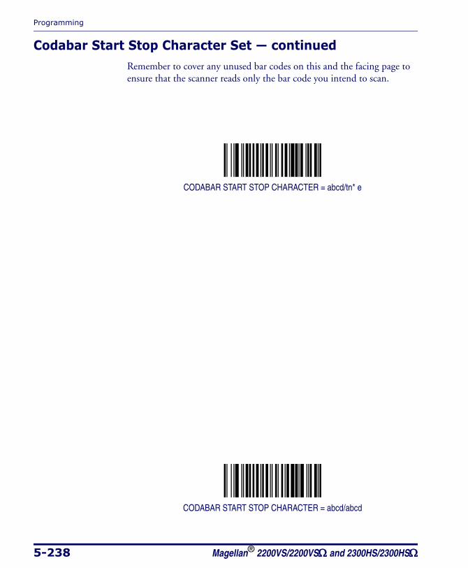
Programming
5-238 Magellan® 2200VS/2200VSΩ and 2300HS/2300HSΩ
Codabar Start Stop Character Set — continuedRemember to cover any unused bar codes on this and the facing page to ensure that the scanner reads only the bar code you intend to scan.
CODABAR START STOP CHARACTER = abcd/tn* e
CODABAR START STOP CHARACTER = abcd/abcd
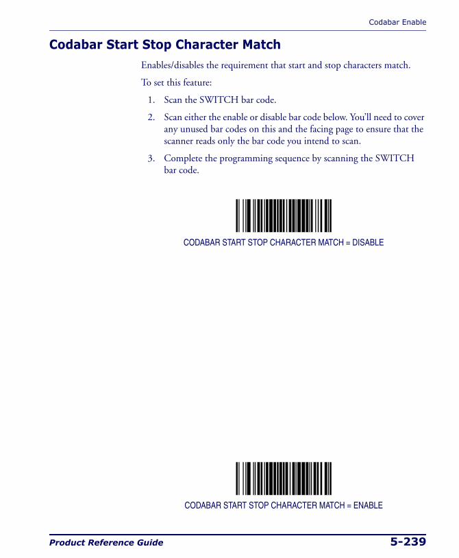
Codabar Enable
Product Reference Guide 5-239
Codabar Start Stop Character MatchEnables/disables the requirement that start and stop characters match.
To set this feature:
1. Scan the SWITCH bar code.
2. Scan either the enable or disable bar code below. You’ll need to cover any unused bar codes on this and the facing page to ensure that the scanner reads only the bar code you intend to scan.
3. Complete the programming sequence by scanning the SWITCH bar code.
CODABAR START STOP CHARACTER MATCH = DISABLE
CODABAR START STOP CHARACTER MATCH = ENABLE
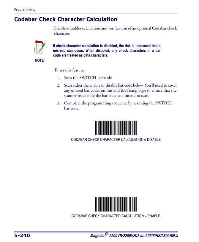
Programming
5-240 Magellan® 2200VS/2200VSΩ and 2300HS/2300HSΩ
Codabar Check Character CalculationEnables/disables calculation and verification of an optional Codabar check character.
To set this feature:
1. Scan the SWITCH bar code.
2. Scan either the enable or disable bar code below. You’ll need to cover any unused bar codes on this and the facing page to ensure that the scanner reads only the bar code you intend to scan.
3. Complete the programming sequence by scanning the SWITCH bar code.
CODABAR CHECK CHARACTER CALCULATION = DISABLE
CODABAR CHECK CHARACTER CALCULATION = ENABLE
NOTE
If check character calculation is disabled, the risk is increased that a misread can occur. When disabled, any check characters in a bar code are treated as data characters.
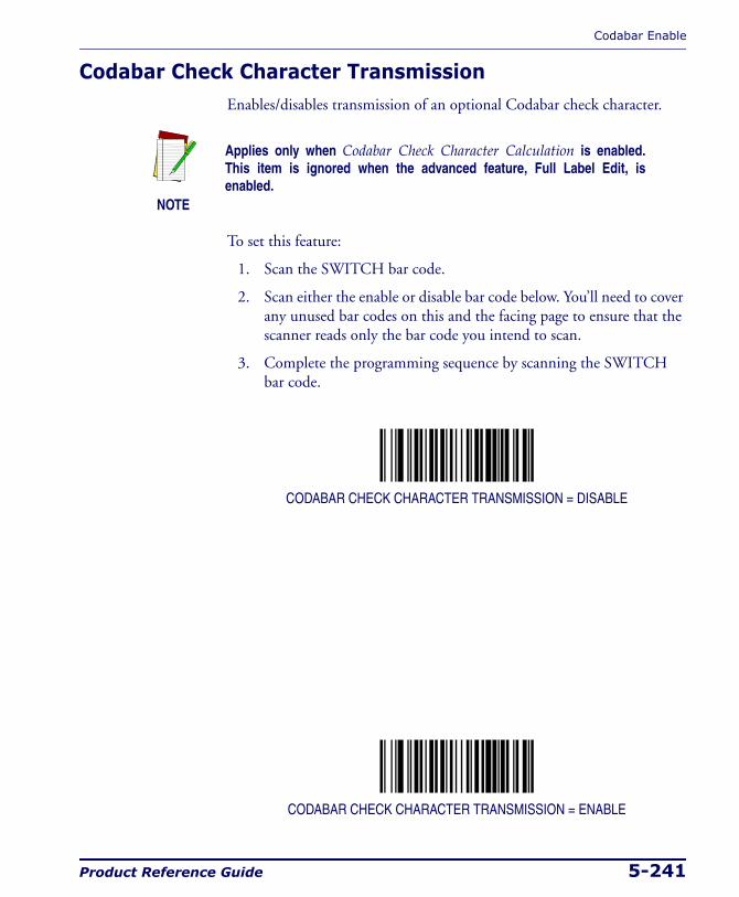
Codabar Enable
Product Reference Guide 5-241
Codabar Check Character TransmissionEnables/disables transmission of an optional Codabar check character.
To set this feature:
1. Scan the SWITCH bar code.
2. Scan either the enable or disable bar code below. You’ll need to cover any unused bar codes on this and the facing page to ensure that the scanner reads only the bar code you intend to scan.
3. Complete the programming sequence by scanning the SWITCH bar code.
CODABAR CHECK CHARACTER TRANSMISSION = DISABLE
CODABAR CHECK CHARACTER TRANSMISSION = ENABLE
NOTE
Applies only when Codabar Check Character Calculation is enabled. This item is ignored when the advanced feature, Full Label Edit, is enabled.
Programming
5-242 Magellan® 2200VS/2200VSΩ and 2300HS/2300HSΩ
Codabar AIM IDThis feature enables/disables transmission of the Codabar AIM symbology identifier.
To set this feature:
1. Scan the SWITCH bar code.
2. Scan your selection from the bar codes below. You’ll need to cover any unused bar codes on this and the facing page to ensure that the scanner reads only the bar code you intend to scan.
3. Complete the programming sequence by scanning the SWITCH bar code.
CODABAR AIM ID = DISABLE
CODABAR AIM ID = ENABLE

Codabar Enable
Product Reference Guide 5-243
Codabar Label IDThis feature specifies a Codabar label ID to e added to bar code data.
To set this feature:
1. Scan the SWITCH bar code.
2. Scan the bar code, SET CODABAR LABEL ID below. You’ll need to cover any unused bar codes on this and the facing page to ensure the scanner reads only the bar code you intend to scan.
3. Scan the appropriate digits from the keypad in Appendix C that rep-resent the desired Label ID characters; entered as two hex pairs. A table containing the ASCII Character Set and their corresponding Hex Values is available in the inside back cover of this manual. ASCII parameters must be input by scanning a pair of hexadecimal digits for each character. Thus, to set a two-character value of AB, bar codes containing the digits ‘4’, ‘1’, ‘4’, and ‘2’ must be scanned. The selectable range for this option is any hex value from 00 to FF.
4. Complete the programming sequence by scanning the SWITCH bar code.
SET CODABAR LABEL ID
NOTE
The programming feature, RS-232 Label ID Control, designates whether the Label ID is transmitted as a prefix or suffix or if Label ID is disabled.

Programming
5-244 Magellan® 2200VS/2200VSΩ and 2300HS/2300HSΩ
Codabar Length ControlThis feature specifies whether variable-length or fixed-length decoding will be set for Codabar.
To set this feature:
1. Scan the SWITCH bar code.
2. Scan your selection from the bar codes below. You’ll need to cover any unused bar codes on this and the facing page to ensure that the scanner reads only the bar code you intend to scan.
3. Complete the programming sequence by scanning the SWITCH bar code.
CODABAR LENGTH CONTROL = VARIABLE-LENGTH
CODABAR LENGTH CONTROL = FIXED-LENGTH
NOTE
If variable-length control was selected, you must now set the fea-tures Codabar Maximum Label Length and Codabar Minimum Label Length. If fixed-length control was selected, you must now set Codabar Fixed Length 1 and Codabar Fixed Length 2.

Codabar Enable
Product Reference Guide 5-245
Codabar Maximum Label LengthThis feature specifies the maximum allowable length of a Codabar label.
To set this feature:
1. Scan the SWITCH bar code.
2. Scan the bar code, SET CODABAR MAXIMUM LABEL LENGTH below. You’ll need to cover any unused bar codes on this and the fac-ing page to ensure that the scanner reads only the bar code you intend to scan.
3. Scan the appropriate digits from the keypad in Appendix C that rep-resent the desired maximum label length. The selectable range for this option is 03 to 50. Pad all single digit numbers with a leading zero to yield a two-digit entry (03-50).
4. Complete the programming sequence by scanning the SWITCH bar code.
SET CODABAR MAXIMUM LABEL LENGTH
NOTE
Length in this case includes start, stop or check and data characters, but does not include full ASCII shift characters. This feature applies when Codabar Length Control is set to variable-length decoding.
Maximum label length should be greater than or equal to minimum label length.
Programming
5-246 Magellan® 2200VS/2200VSΩ and 2300HS/2300HSΩ
Codabar Minimum Label LengthThis feature specifies the minimum allowable length of a Codabar label.
To set this feature:
1. Scan the SWITCH bar code.
2. Scan the bar code, SET CODABAR MINIMUM LABEL LENGTH below. You’ll need to cover any unused bar codes on this and the fac-ing page to ensure that the scanner reads only the bar code you intend to scan.
3. Scan the appropriate digits from the keypad in Appendix C that rep-resent the desired minimum label length. The selectable range for this option is 03 to 50. Pad all single digit numbers with a leading zero to yield a two-digit entry (03-50).
4. Complete the programming sequence by scanning the SWITCH bar code.
SET CODABAR MINIMUM LABEL LENGTH
NOTE
Length in this case includes start, stop or check and data charac-ters, but does not include full ASCII shift characters. This feature applies when Codabar Length Control is set to variable-length decoding.
Minimum label length should be less than or equal to maximum label length.

Codabar Enable
Product Reference Guide 5-247
Codabar Fixed Length 1This feature specifies Codabar first fixed length.
To set this feature:
1. Scan the SWITCH bar code.
2. Scan the bar code, SET CODABAR FIXED LENGTH 1 below. You’ll need to cover any unused bar codes on this and the facing page to ensure that the scanner reads only the bar code you intend to scan.
3. Scan the appropriate digits from the keypad in Appendix C that rep-resent the desired fixed label length. The selectable range for this option is 03 to 50. Pad all single digit numbers with a leading zero to yield a two-digit entry (03-50).
4. Complete the programming sequence by scanning the SWITCH bar code.
SET CODABAR FIXED LENGTH 1
NOTE
Length in this case includes start, stop or check and data characters, but does not include full ASCII shift characters.
This feature applies when Codabar Length Control is set to fixed-length decoding.
Decodable length is four when the optional check character is present.
Programming
5-248 Magellan® 2200VS/2200VSΩ and 2300HS/2300HSΩ
Codabar Fixed Length 2This feature specifies Codabar second fixed length.
To set this feature:
1. Scan the SWITCH bar code.
2. Scan the bar code, SET CODABAR FIXED LENGTH 2 below. You’ll need to cover any unused bar codes on this and the facing page to ensure that the scanner reads only the bar code you intend to scan.
3. Scan the appropriate digits from the keypad in Appendix C that rep-resent the desired fixed label length. The selectable range for this option is 00, or 03 to 50. Pad all single digit numbers with a leading zero to yield a two-digit entry (03-50).
4. Complete the programming sequence by scanning the SWITCH bar code.
SET CODABAR FIXED LENGTH 2
NOTE
Length in this case includes start, stop or check and data charac-ters, but does not include full ASCII shift characters.
This feature applies when Codabar Length Control is set to fixed-length decoding.
Decodable length is four when the optional check character is present.
If Fixed Length 2 is set to 00 (zero), then Fixed Length 1 will apply.

Codabar Enable
Product Reference Guide 5-249
Codabar StitchingEnables/disables stitching for Codabar labels. When parts of a Codabar bar code are presented to the scanner with this feature enabled, the bar code parts will be assembled by the scanner’s software, and the data will be decoded if all bar code proofing requirements are met.
To set this feature:
1. Scan the SWITCH bar code.
2. Scan your selection from the bar codes below. You’ll need to cover any unused bar codes on this and the facing page to ensure that the scanner reads only the bar code you intend to scan.
Complete the programming sequence by scanning the SWITCH bar code.
CODABAR STITCHING = DISABLE
CODABAR STITCHING = ENABLE
Programming
5-250 Magellan® 2200VS/2200VSΩ and 2300HS/2300HSΩ
Code 93 EnableEnables/disables the ability of the scanner to decode Code 93 labels.
To set this feature:
1. Scan the SWITCH bar code.
2. Scan either the enable or disable bar code below. You’ll need to cover any unused bar codes on this and the facing page to ensure that the scanner reads only the bar code you intend to scan.
3. Complete the programming sequence by scanning the SWITCH bar code.
CODE 93 = DISABLE
CODE 93 = ENABLE

Code 93 Enable
Product Reference Guide 5-251
Code 93 AIM IDThis feature enables/disables transmission of the Code 93 AIM symbology identifier.
To set this feature:
1. Scan the SWITCH bar code.
2. Scan your selection from the bar codes below. You’ll need to cover any unused bar codes on this and the facing page to ensure that the scanner reads only the bar code you intend to scan.
3. Complete the programming sequence by scanning the SWITCH bar code.
CODE 93 AIM ID = DISABLE
CODE 93 AIM ID = ENABLE
Programming
5-252 Magellan® 2200VS/2200VSΩ and 2300HS/2300HSΩ
Code 93 Label IDThis feature specifies a Code 93 label ID to be added to bar code data.
To set this feature:
1. Scan the SWITCH bar code.
2. Scan the bar code, SET CODE 93 LABEL ID below. You’ll need to cover any unused bar codes on this and the facing page to ensure the scanner reads only the bar code you intend to scan.
3. Scan the appropriate digits from the keypad in Appendix C that rep-resent the desired Label ID characters; entered as two hex pairs. A table containing the ASCII Character Set and their corresponding Hex Values is available in the inside back cover of this manual. ASCII parameters must be input by scanning a pair of hexadecimal digits for each character. Thus, to set a two-character value of AB, bar codes containing the digits ‘4’, ‘1’, ‘4’, and ‘2’ must be scanned. The selectable range for this option is any hex value from 00 to FF.
4. Complete the programming sequence by scanning the SWITCH bar code.
SET CODE 93 LABEL ID
NOTE
The programming feature, RS-232 Label ID Control, designates whether the Label ID is transmitted as a prefix or suffix or if Label ID is disabled.

Code 93 Enable
Product Reference Guide 5-253
Code 93 Length ControlThis feature specifies whether variable-length or fixed-length decoding will be set for Code 93.
To set this feature:
1. Scan the SWITCH bar code.
2. Scan your selection from the bar codes below. You’ll need to cover any unused bar codes on this and the facing page to ensure that the scanner reads only the bar code you intend to scan.
3. Complete the programming sequence by scanning the SWITCH bar code.
CODE 93 LENGTH CONTROL = VARIABLE-LENGTH
CODE 93 LENGTH CONTROL = FIXED-LENGTH
NOTE
If variable-length control was selected, you must now set the features Code 93 Maximum Label Length and Code 93 Minimum Label Length. If fixed-length control was selected, you must now set Code 93 Fixed Length 1 and Code 93 Fixed Length 2.
Programming
5-254 Magellan® 2200VS/2200VSΩ and 2300HS/2300HSΩ
Code 93 Maximum Label LengthThis feature specifies the maximum allowable length of a Code 93 label.
To set this feature:
1. Scan the SWITCH bar code.
2. Scan the bar code, SET CODE 93 MAXIMUM LABEL LENGTH below. You’ll need to cover any unused bar codes on this and the fac-ing page to ensure that the scanner reads only the bar code you intend to scan.
3. Scan the appropriate digits from the keypad in Appendix C that rep-resent the desired maximum label length. The selectable range for this option is 01 to 50. Pad all single digit numbers with a leading zero to yield a two-digit entry (01-50).
4. Complete the programming sequence by scanning the SWITCH bar code.
SET CODE 93 MAXIMUM LABEL LENGTH
NOTE
Length in this case includes data characters, but does not include start, stop, full ASCII shift, or check characters. This feature applies when Code 93 Length Control is set to variable-length decoding.
Maximum label length should be greater than or equal to minimum label length.
Code 93 Enable
Product Reference Guide 5-255
Code 93 Minimum Label LengthThis feature specifies the minimum allowable length of a Code 93 label.
To set this feature:
1. Scan the SWITCH bar code.
2. Scan the bar code, SET CODE 93 MINIMUM LABEL LENGTH below. You’ll need to cover any unused bar codes on this and the fac-ing page to ensure that the scanner reads only the bar code you intend to scan.
3. Scan the appropriate digits from the keypad in Appendix C that rep-resent the desired minimum label length. The selectable range for this option is 01 to 50. Pad all single digit numbers with a leading zero to yield a two-digit entry (01-50).
4. Complete the programming sequence by scanning the SWITCH bar code.
SET CODE 93 MINIMUM LABEL LENGTH
NOTE
Length in this case includes data characters, but does not include start, stop, full ASCII shift, or check characters. This feature applies when Code 93 Length Control is set to variable-length decoding.
Minimum label length should be less than or equal to maximum label length.

Programming
5-256 Magellan® 2200VS/2200VSΩ and 2300HS/2300HSΩ
Code 93 Fixed Length 1This feature specifies Code 93 first fixed length.
To set this feature:
1. Scan the SWITCH bar code.
2. Scan the bar code, SET CODE 93 FIXED LENGTH 1 below. You’ll need to cover any unused bar codes on this and the facing page to ensure that the scanner reads only the bar code you intend to scan.
3. Scan the appropriate digits from the keypad in Appendix C that rep-resent the desired fixed label length. The selectable range for this option is 01 to 50. Pad all single digit numbers with a leading zero to yield a two-digit entry (01-50).
4. Complete the programming sequence by scanning the SWITCH bar code.
SET CODE 93 FIXED LENGTH 1
NOTE
This applies when Code 93 Length Control is set to fixed-length decoding.
Code 93 Enable
Product Reference Guide 5-257
Code 93 Fixed Length 2This feature specifies Code 93 second fixed length.
To set this feature:
1. Scan the SWITCH bar code.
2. Scan the bar code, SET CODE 93 FIXED LENGTH 2 below. You’ll need to cover any unused bar codes on this and the facing page to ensure that the scanner reads only the bar code you intend to scan.
3. Scan the appropriate digits from the keypad in Appendix C that rep-resent the desired fixed label length. The selectable range for this option is 00, or 01 to 50. Pad all single digit numbers with a leading zero to yield a two-digit entry (01-50).
4. Complete the programming sequence by scanning the SWITCH bar code.
SET CODE 93 FIXED LENGTH 2
NOTE
This applies when Code 93 Length Control is set to fixed-length decoding.
If Fixed Length 2 is set to 00 (zero), then Fixed Length 1 will apply.
Programming
5-258 Magellan® 2200VS/2200VSΩ and 2300HS/2300HSΩ
Code 93 StitchingEnables/disables stitching for Code 93 labels. When parts of a Code 93 bar code are presented to the scanner with this feature enabled, the bar code parts will be assembled by the scanner’s software, and the data will be decoded if all bar code proofing requirements are met.
To set this feature:
1. Scan the SWITCH bar code.
2. Scan your selection from the bar codes below. You’ll need to cover any unused bar codes on this and the facing page to ensure that the scanner reads only the bar code you intend to scan.
Complete the programming sequence by scanning the SWITCH bar code.
CODE 93 STITCHING = DISABLE
CODE 93 STITCHING = ENABLE
MSI/Plessey Enable
Product Reference Guide 5-259
MSI/Plessey EnableEnables/disables the ability of the scanner to decode MSI/Plessey labels.
To set this feature:
1. Scan the SWITCH bar code.
2. Scan either the enable or disable bar code below. You’ll need to cover any unused bar codes on this and the facing page to ensure that the scanner reads only the bar code you intend to scan.
3. Complete the programming sequence by scanning the SWITCH bar code.
MSI/PLESSEY = DISABLE
MSI/PLESSEY = ENABLE
Programming
5-260 Magellan® 2200VS/2200VSΩ and 2300HS/2300HSΩ
MSI/Plessey Check Character CalculationEnables/disables calculation and verification of optional MSI/Plessey check characters.
To set this feature:
1. Scan the SWITCH bar code.
2. Scan either the enable or disable bar code below. You’ll need to cover any unused bar codes on this and the facing page to ensure that the scanner reads only the bar code you intend to scan.
3. Complete the programming sequence by scanning the SWITCH bar code.
MSI/PLESSEY CHECK CHARACTER CALCULATION = DISABLE
MSI/PLESSEY CHECK CHARACTER CALCULATION = ENABLE
NOTE
If check character calculation is disabled, the risk is increased that a misread can occur. When disabled, any check characters in a bar code are treated as data characters.
MSI/Plessey Enable
Product Reference Guide 5-261
MSI/Plessey Number of Check CharactersSpecifies number of MSI/Plessey check characters to be calculated and verified.
To set this feature:
1. Scan the SWITCH bar code.
2. Scan the bar code below representing the desired number of MSI/Plessey check characters to be calculated and verified. You’ll need to cover any unused bar codes on this and the facing page to ensure that the scanner reads only the bar code you intend to scan.
3. Complete the programming sequence by scanning the SWITCH bar code.
MSI/PLESSEY NUMBER OF CHECK CHARACTERS = 1
MSI/PLESSEY NUMBER OF CHECK CHARACTERS = 2
NOTE
Check characters are always modulus 10.
Programming
5-262 Magellan® 2200VS/2200VSΩ and 2300HS/2300HSΩ
MSI/Plessey Check Character TransmissionEnables/disables transmission of optional MSI/Plessey check characters.
To set this feature:
1. Scan the SWITCH bar code.
2. Scan either the enable or disable bar code below. You’ll need to cover any unused bar codes on this and the facing page to ensure that the scanner reads only the bar code you intend to scan.
3. Complete the programming sequence by scanning the SWITCH bar code.
MSI/PLESSEY CHECK CHARACTER TRANSMISSION = DISABLE
MSI/PLESSEY CHECK CHARACTER TRANSMISSION = ENABLE
NOTE
This feature applies only when MSI/Plessey Check Character Calcu-lation is enabled. This item is ignored when the advanced feature, Full Label Edit, is enabled.
MSI/Plessey Enable
Product Reference Guide 5-263
MSI/Plessey AIM IDThis feature enables/disables transmission of the MSI/Plessey AIM sym-bology identifier.
To set this feature:
1. Scan the SWITCH bar code.
2. Scan your selection from the bar codes below. You’ll need to cover any unused bar codes on this and the facing page to ensure that the scanner reads only the bar code you intend to scan.
3. Complete the programming sequence by scanning the SWITCH bar code.
MSI/PLESSEY AIM ID = DISABLE
MSI/PLESSEY AIM ID = ENABLE
Programming
5-264 Magellan® 2200VS/2200VSΩ and 2300HS/2300HSΩ
MSI/Plessey Label IDThis feature specifies an MSI/Plessey label ID to be added to bar code data.
To set this feature:
1. Scan the SWITCH bar code.
2. Scan the bar code, SET MSI/PLESSEY LABEL ID below. You’ll need to cover any unused bar codes on this and the facing page to ensure the scanner reads only the bar code you intend to scan.
3. Scan the appropriate digits from the keypad in Appendix C that rep-resent the desired Label ID characters; entered as two hex pairs. A table containing the ASCII Character Set and their corresponding Hex Values is available in the inside back cover of this manual. ASCII parameters must be input by scanning a pair of hexadecimal digits for each character. Thus, to set a two-character value of AB, bar codes containing the digits ‘4’, ‘1’, ‘4’, and ‘2’ must be scanned. The selectable range for this option is any hex value from 00 to FF.
4. Complete the programming sequence by scanning the SWITCH bar code.
SET MSI/PLESSEY LABEL ID
NOTE
The programming feature, RS-232 Label ID Control, designates whether the Label ID is transmitted as a prefix or suffix or if Label ID is disabled.
MSI/Plessey Enable
Product Reference Guide 5-265
MSI/Plessey Length ControlThis feature specifies whether variable-length or fixed-length decoding will be set for MSI/Plessey.
To set this feature:
1. Scan the SWITCH bar code.
2. Scan your selection from the bar codes below. You’ll need to cover any unused bar codes on this and the facing page to ensure that the scanner reads only the bar code you intend to scan.
3. Complete the programming sequence by scanning the SWITCH bar code.
MSI/PLESSEY LENGTH CONTROL = VARIABLE-LENGTH
MSI/PLESSEY LENGTH CONTROL = FIXED-LENGTH
NOTE
If variable-length control was selected, you must now set the features MSI/Plessey Maximum Label Length and MSI/Plessey Minimum Label Length. If fixed-length control was selected, you must now set I 2 of 5 Fixed Length 1 and MSI/Plessey Fixed Length 2.
Programming
5-266 Magellan® 2200VS/2200VSΩ and 2300HS/2300HSΩ
MSI/Plessey Maximum Label LengthThis feature specifies the maximum allowable length of an MSI/Plessey label.
To set this feature:
1. Scan the SWITCH bar code.
2. Scan the bar code, SET MSI/PLESSEY MAXIMUM LABEL LENGTH below. You’ll need to cover any unused bar codes on this and the facing page to ensure that the scanner reads only the bar code you intend to scan.
3. Scan the appropriate digits from the keypad in Appendix C that rep-resent the desired maximum label length. The selectable range for this option is 4 to 16. Pad all single digit numbers with a leading zero to yield a two-digit entry (04-16).
4. Complete the programming sequence by scanning the SWITCH bar code.
SET MSI/PLESSEY MAXIMUM LABEL LENGTH
NOTE
Length in this case includes check and data characters, but does not include start, stop or full ASCII shift characters. This feature applies when MSI/Plessey Length Control is set to variable-length decoding.
Maximum label length should be greater than or equal to minimum label length.
MSI/Plessey Enable
Product Reference Guide 5-267
MSI/Plessey Minimum Label LengthThis feature specifies the minimum allowable length of an MSI/Plessey label.
To set this feature:
1. Scan the SWITCH bar code.
2. Scan the bar code, SET MSI/PLESSEY MINIMUM LABEL LENGTH below. You’ll need to cover any unused bar codes on this and the facing page to ensure that the scanner reads only the bar code you intend to scan.
3. Scan the appropriate digits from the keypad in Appendix C that rep-resent the desired minimum label length. The selectable range for this option is 4 to 16. Pad all single digit numbers with a leading zero to yield a two-digit entry (04-16).
4. Complete the programming sequence by scanning the SWITCH bar code.
SET MSI/PLESSEY MINIMUM LABEL LENGTH
NOTE
Length in this case includes check and data characters, but does not include start, stop or full ASCII shift characters. This applies when MSI/Plessey Length Control is set to variable-length decoding.
Minimum label length should be less than or equal to maximum label length.
Programming
5-268 Magellan® 2200VS/2200VSΩ and 2300HS/2300HSΩ
MSI/Plessey Fixed Length 1This feature specifies MSI/Plessey first fixed length.
To set this feature:
1. Scan the SWITCH bar code.
2. Scan the bar code, SET MSI/PLESSEY FIXED LENGTH 1 below. You’ll need to cover any unused bar codes on this and the facing page to ensure that the scanner reads only the bar code you intend to scan.
3. Scan the appropriate digits from the keypad in Appendix C that rep-resent the desired fixed label length. The selectable range for this option is 4 to 16. Pad all single digit numbers with a leading zero to yield a two-digit entry (04-16).
4. Complete the programming sequence by scanning the SWITCH bar code.
SET MSI/PLESSEY FIXED LENGTH 1
NOTE
This applies when MSI/Plessey Length Control is set to fixed-length decoding.
MSI/Plessey Enable
Product Reference Guide 5-269
MSI/Plessey Fixed Length 2This feature specifies MSI/Plessey second fixed length.
To set this feature:
1. Scan the SWITCH bar code.
2. Scan the bar code, SET MSI/PLESSEY FIXED LENGTH 2 below. You’ll need to cover any unused bar codes on this and the facing page to ensure that the scanner reads only the bar code you intend to scan.
3. Scan the appropriate digits from the keypad in Appendix C that rep-resent the desired fixed label length. The selectable range for this option is 0 (zero), or 4 to 16. Pad all single digit numbers with a leading zero to yield a two-digit entry (00, 04-16).
4. Complete the programming sequence by scanning the SWITCH bar code.
SET MSI/PLESSEY FIXED LENGTH 2
NOTE
This applies when MSI/Plessey Length Control is set to fixed-length decoding.
If Fixed Length 2 is set to 00 (zero), then Fixed Length 1 will apply.
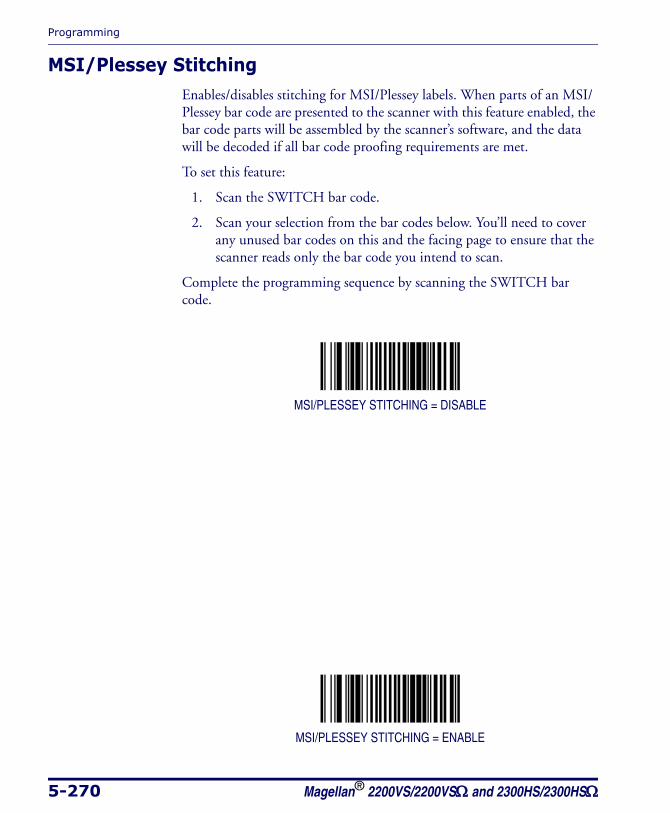
Programming
5-270 Magellan® 2200VS/2200VSΩ and 2300HS/2300HSΩ
MSI/Plessey StitchingEnables/disables stitching for MSI/Plessey labels. When parts of an MSI/Plessey bar code are presented to the scanner with this feature enabled, the bar code parts will be assembled by the scanner’s software, and the data will be decoded if all bar code proofing requirements are met.
To set this feature:
1. Scan the SWITCH bar code.
2. Scan your selection from the bar codes below. You’ll need to cover any unused bar codes on this and the facing page to ensure that the scanner reads only the bar code you intend to scan.
Complete the programming sequence by scanning the SWITCH bar code.
MSI/PLESSEY STITCHING = DISABLE
MSI/PLESSEY STITCHING = ENABLE
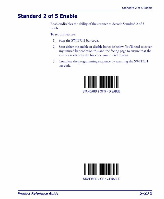
Standard 2 of 5 Enable
Product Reference Guide 5-271
Standard 2 of 5 EnableEnables/disables the ability of the scanner to decode Standard 2 of 5 labels.
To set this feature:
1. Scan the SWITCH bar code.
2. Scan either the enable or disable bar code below. You’ll need to cover any unused bar codes on this and the facing page to ensure that the scanner reads only the bar code you intend to scan.
3. Complete the programming sequence by scanning the SWITCH bar code.
STANDARD 2 OF 5 = DISABLE
STANDARD 2 OF 5 = ENABLE
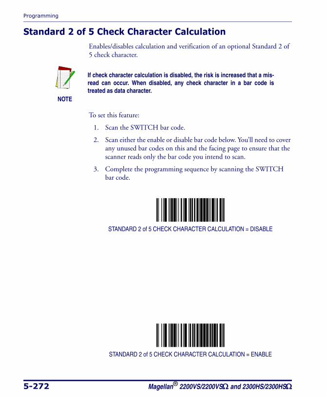
Programming
5-272 Magellan® 2200VS/2200VSΩ and 2300HS/2300HSΩ
Standard 2 of 5 Check Character CalculationEnables/disables calculation and verification of an optional Standard 2 of 5 check character.
To set this feature:
1. Scan the SWITCH bar code.
2. Scan either the enable or disable bar code below. You’ll need to cover any unused bar codes on this and the facing page to ensure that the scanner reads only the bar code you intend to scan.
3. Complete the programming sequence by scanning the SWITCH bar code.
STANDARD 2 of 5 CHECK CHARACTER CALCULATION = DISABLE
STANDARD 2 of 5 CHECK CHARACTER CALCULATION = ENABLE
NOTE
If check character calculation is disabled, the risk is increased that a mis-read can occur. When disabled, any check character in a bar code is treated as data character.
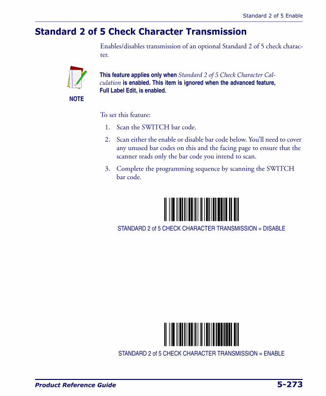
Standard 2 of 5 Enable
Product Reference Guide 5-273
Standard 2 of 5 Check Character TransmissionEnables/disables transmission of an optional Standard 2 of 5 check charac-ter.
To set this feature:
1. Scan the SWITCH bar code.
2. Scan either the enable or disable bar code below. You’ll need to cover any unused bar codes on this and the facing page to ensure that the scanner reads only the bar code you intend to scan.
3. Complete the programming sequence by scanning the SWITCH bar code.
STANDARD 2 of 5 CHECK CHARACTER TRANSMISSION = DISABLE
STANDARD 2 of 5 CHECK CHARACTER TRANSMISSION = ENABLE
NOTE
This feature applies only when Standard 2 of 5 Check Character Cal-culation is enabled. This item is ignored when the advanced feature, Full Label Edit, is enabled.

Programming
5-274 Magellan® 2200VS/2200VSΩ and 2300HS/2300HSΩ
Standard 2 of 5 AIM IDThis feature enables/disables transmission of the Standard 2 of 5 AIM symbology identifier.
To set this feature:
1. Scan the SWITCH bar code.
2. Scan your selection from the bar codes below. You’ll need to cover any unused bar codes on this and the facing page to ensure that the scanner reads only the bar code you intend to scan.
3. Complete the programming sequence by scanning the SWITCH bar code.
STANDARD 2 of 5 AIM ID = DISABLE
STANDARD 2 of 5 AIM ID = ENABLE
Standard 2 of 5 Enable
Product Reference Guide 5-275
Standard 2 of 5 Label IDThis feature specifies an Standard 2 of 5 label ID to be added to bar code data.
To set this feature:
1. Scan the SWITCH bar code.
2. Scan the bar code, SET STANDARD 2 of 5 LABEL ID below. You’ll need to cover any unused bar codes on this and the facing page to ensure the scanner reads only the bar code you intend to scan.
3. Scan the appropriate digits from the keypad in Appendix C that rep-resent the desired Label ID characters; entered as two hex pairs. A table containing the ASCII Character Set and their corresponding Hex Values is available in the inside back cover of this manual. ASCII parameters must be input by scanning a pair of hexadecimal digits for each character. Thus, to set a two-character value of AB, bar codes containing the digits ‘4’, ‘1’, ‘4’, and ‘2’ must be scanned. The selectable range for this option is any hex value from 00 to FF.
4. Complete the programming sequence by scanning the SWITCH bar code.
SET STANDARD 2 of 5 LABEL ID
NOTE
The programming feature, RS-232 Label ID Control, designates whether the Label ID is transmitted as a prefix or suffix or if Label ID is disabled.

Programming
5-276 Magellan® 2200VS/2200VSΩ and 2300HS/2300HSΩ
Standard 2 of 5 Length ControlThis feature specifies whether variable-length or fixed-length decoding will be set for Standard 2 of 5.
To set this feature:
1. Scan the SWITCH bar code.
2. Scan your selection from the bar codes below. You’ll need to cover any unused bar codes on this and the facing page to ensure that the scanner reads only the bar code you intend to scan.
3. Complete the programming sequence by scanning the SWITCH bar code.
STANDARD 2 OF 5 LENGTH CONTROL = VARIABLE-LENGTH
STANDARD 2 OF 5 LENGTH CONTROL = FIXED-LENGTH
NOTE
If variable-length control was selected, you must now set the features Standard 2 of 5 Maximum Label Length and Standard 2 of 5 Mini-mum Label Length. If fixed-length control was selected, you must now set Standard 2 of 5 Fixed Length 1 and Standard 2 of 5 Fixed Length 2.
Standard 2 of 5 Enable
Product Reference Guide 5-277
Standard 2 of 5 Maximum Label LengthThis feature specifies the maximum allowable length of a Standard 2 of 5 label.
To set this feature:
1. Scan the SWITCH bar code.
2. Scan the bar code, SET STANDARD 2 OF 5 MAXIMUM LABEL LENGTH below. You’ll need to cover any unused bar codes on this and the facing page to ensure that the scanner reads only the bar code you intend to scan.
3. Scan the appropriate digits from the keypad in Appendix C that rep-resent the desired maximum label length. The selectable range for this option is 01 to 50, even numbers only. Pad all single digit num-bers with a leading zero to yield a two-digit entry (01-50).
4. Complete the programming sequence by scanning the SWITCH bar code.
SET STANDARD 2 OF 5 MAXIMUM LABEL LENGTH
NOTE
Length in this case includes check and data characters, but does not include start or stop characters. This feature applies when Standard 2 of 5 Length Control is set to variable-length decoding.
Maximum label length should be greater than or equal to minimum label length.

Programming
5-278 Magellan® 2200VS/2200VSΩ and 2300HS/2300HSΩ
Standard 2 of 5 Minimum Label LengthThis feature specifies the minimum allowable length of an Standard 2 of 5 label.
To set this feature:
1. Scan the SWITCH bar code.
2. Scan the bar code, SET STANDARD 2 OF 5 MINIMUM LABEL LENGTH below. You’ll need to cover any unused bar codes on this and the facing page to ensure that the scanner reads only the bar code you intend to scan.
3. Scan the appropriate digits from the keypad in Appendix C that rep-resent the desired minimum label length. The selectable range for this option is 01 to 50, even numbers only. Pad all single digit num-bers with a leading zero to yield a two-digit entry (01-50).
4. Complete the programming sequence by scanning the SWITCH bar code.
SET STANDARD 2 OF 5 MINIMUM LABEL LENGTH
NOTE
Length in this case includes check and data characters, but does not include start or stop characters. This feature applies when Standard 2 of 5 Length Control is set to variable-length decoding.
Minimum label length should be less than or equal to maximum label length.
Standard 2 of 5 Enable
Product Reference Guide 5-279
Standard 2 of 5 Fixed Length 1This feature specifies Standard 2 of 5 first fixed length.
To set this feature:
1. Scan the SWITCH bar code.
2. Scan the bar code, SET STANDARD 2 OF 5 FIXED LENGTH 1 below. You’ll need to cover any unused bar codes on this and the fac-ing page to ensure that the scanner reads only the bar code you intend to scan.
3. Scan the appropriate digits from the keypad in Appendix C that rep-resent the desired fixed label length. The selectable range for this option is 1 to 50. Pad all single digit numbers with a leading zero to yield a two-digit entry (01-50).
4. Complete the programming sequence by scanning the SWITCH bar code.
SET STANDARD 2 OF 5 FIXED LENGTH 1
NOTE
This applies when Standard 2 of 5 Length Control is set to fixed-length decoding.
Programming
5-280 Magellan® 2200VS/2200VSΩ and 2300HS/2300HSΩ
Standard 2 of 5 Fixed Length 2This feature specifies Standard 2 of 5 second fixed length.
To set this feature:
1. Scan the SWITCH bar code.
2. Scan the bar code, SET STANDARD 2 OF 5 FIXED LENGTH 2 below. You’ll need to cover any unused bar codes on this and the fac-ing page to ensure that the scanner reads only the bar code you intend to scan.
3. Scan the appropriate digits from the keypad in Appendix C that rep-resent the desired fixed label length. The selectable range for this option is 1 to 50. Pad all single digit numbers with a leading zero to yield a two-digit entry (01-50).
4. Complete the programming sequence by scanning the SWITCH bar code.
SET STANDARD 2 OF 5 FIXED LENGTH 2
NOTE
This applies when Standard 2 of 5 Length Control is set to fixed-length decoding.
If Fixed Length 2 is set to 00 (zero), then Fixed Length 1 will apply.
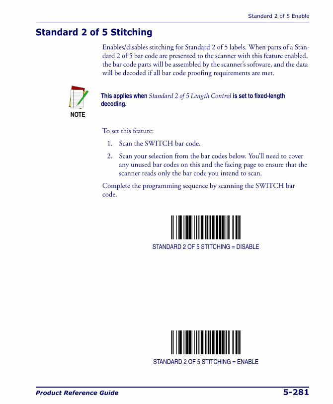
Standard 2 of 5 Enable
Product Reference Guide 5-281
Standard 2 of 5 StitchingEnables/disables stitching for Standard 2 of 5 labels. When parts of a Stan-dard 2 of 5 bar code are presented to the scanner with this feature enabled, the bar code parts will be assembled by the scanner’s software, and the data will be decoded if all bar code proofing requirements are met.
To set this feature:
1. Scan the SWITCH bar code.
2. Scan your selection from the bar codes below. You’ll need to cover any unused bar codes on this and the facing page to ensure that the scanner reads only the bar code you intend to scan.
Complete the programming sequence by scanning the SWITCH bar code.
STANDARD 2 OF 5 STITCHING = DISABLE
STANDARD 2 OF 5 STITCHING = ENABLE
NOTE
This applies when Standard 2 of 5 Length Control is set to fixed-length decoding.

Programming
5-282 Magellan® 2200VS/2200VSΩ and 2300HS/2300HSΩ
NOTES
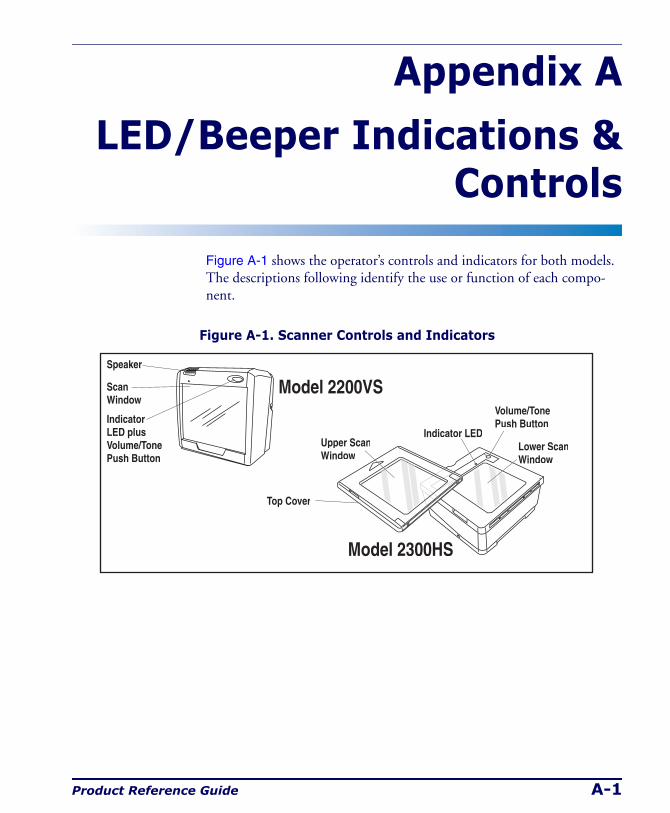
Product Reference Guide A-1
Appendix A
LED/Beeper Indications & Controls
Figure A-1 shows the operator’s controls and indicators for both models. The descriptions following identify the use or function of each compo-nent.
Figure A-1. Scanner Controls and Indicators
Speaker
ScanWindow
Upper ScanWindow
Lower ScanWindow
IndicatorLED plusVolume/TonePush Button
Volume/TonePush Button
Indicator LED
Model 2200VS
Model 2300HS
Top Cover
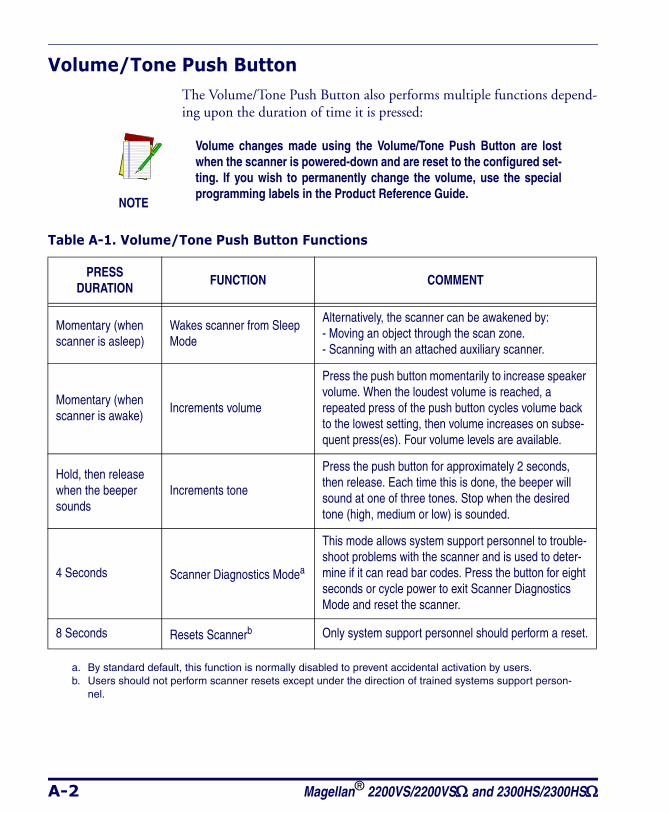
A-2 Magellan® 2200VS/2200VSΩ and 2300HS/2300HSΩ
Volume/Tone Push ButtonThe Volume/Tone Push Button also performs multiple functions depend-ing upon the duration of time it is pressed:
NOTE
Volume changes made using the Volume/Tone Push Button are lost when the scanner is powered-down and are reset to the configured set-ting. If you wish to permanently change the volume, use the special programming labels in the Product Reference Guide.
Table A-1. Volume/Tone Push Button Functions
PRESSDURATION
FUNCTION COMMENT
Momentary (when scanner is asleep)
Wakes scanner from Sleep Mode
Alternatively, the scanner can be awakened by: - Moving an object through the scan zone. - Scanning with an attached auxiliary scanner.
Momentary (when scanner is awake)
Increments volume
Press the push button momentarily to increase speaker volume. When the loudest volume is reached, a repeated press of the push button cycles volume back to the lowest setting, then volume increases on subse-quent press(es). Four volume levels are available.
Hold, then release when the beeper sounds
Increments tone
Press the push button for approximately 2 seconds, then release. Each time this is done, the beeper will sound at one of three tones. Stop when the desired tone (high, medium or low) is sounded.
4 Seconds Scanner Diagnostics Modea
This mode allows system support personnel to trouble-shoot problems with the scanner and is used to deter-mine if it can read bar codes. Press the button for eight seconds or cycle power to exit Scanner Diagnostics Mode and reset the scanner.
8 Seconds Resets Scannerb Only system support personnel should perform a reset.
a. By standard default, this function is normally disabled to prevent accidental activation by users.b. Users should not perform scanner resets except under the direction of trained systems support person-
nel.
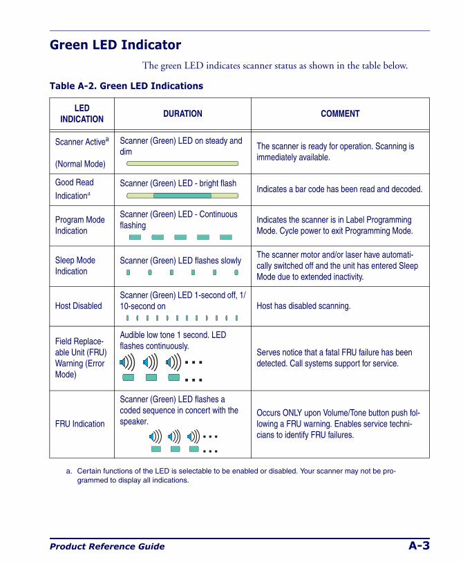
Product Reference Guide A-3
Green LED IndicatorThe green LED indicates scanner status as shown in the table below.
Table A-2. Green LED Indications
LED INDICATION
DURATION COMMENT
Scanner Activea
(Normal Mode)
Scanner (Green) LED on steady and dim
The scanner is ready for operation. Scanning is immediately available.
Good Read
IndicationaScanner (Green) LED - bright flash
Indicates a bar code has been read and decoded.
Program Mode Indication
Scanner (Green) LED - Continuous flashing
Indicates the scanner is in Label Programming Mode. Cycle power to exit Programming Mode.
Sleep Mode Indication
Scanner (Green) LED flashes slowlyThe scanner motor and/or laser have automati-cally switched off and the unit has entered Sleep Mode due to extended inactivity.
Host DisabledScanner (Green) LED 1-second off, 1/10-second on Host has disabled scanning.
Field Replace-able Unit (FRU) Warning (Error Mode)
Audible low tone 1 second. LED flashes continuously.
Serves notice that a fatal FRU failure has been detected. Call systems support for service.
FRU Indication
Scanner (Green) LED flashes a coded sequence in concert with the speaker.
Occurs ONLY upon Volume/Tone button push fol-lowing a FRU warning. Enables service techni-cians to identify FRU failures.
a. Certain functions of the LED is selectable to be enabled or disabled. Your scanner may not be pro-grammed to display all indications.

A-4 Magellan® 2200VS/2200VSΩ and 2300HS/2300HSΩ
NOTES
Product Reference Guide B-1
Appendix B
Cable Information
IntroductionThe following pages contain pinout information, enabling you to create standard interface cables for use in interconnecting the scanner, external handheld scanner, and POS terminal.
General Specifications
Wire Requirements
• Cable length should not exceed 15 feet.
• Wire gauge = Standard for RJ-45 connectors (28-26 AWG).
• If run exceeds 15 feet, we recommend 26 AWG wire size.
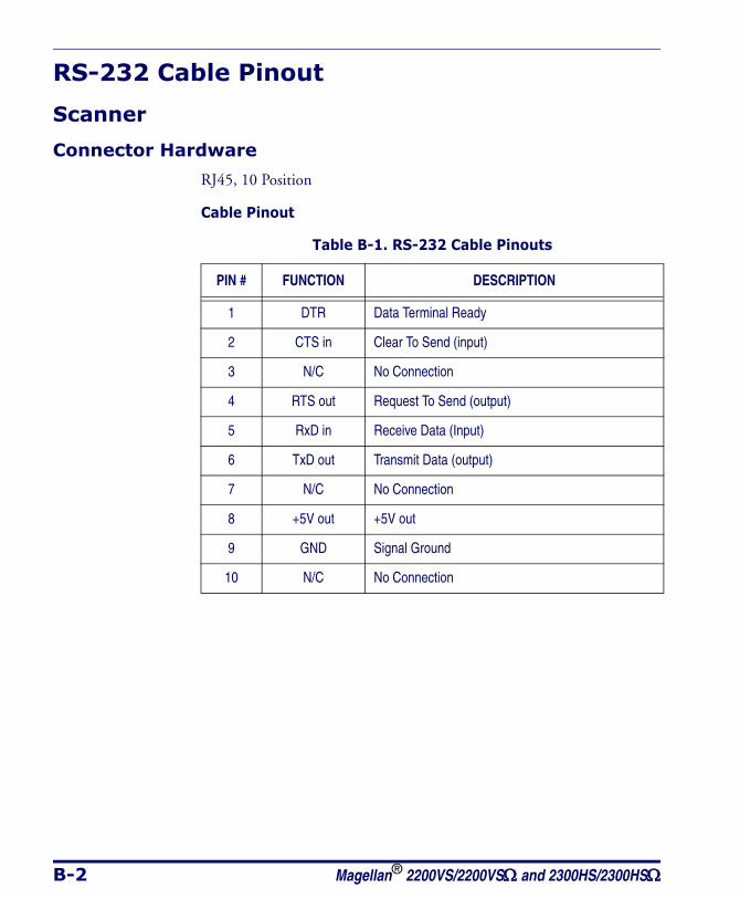
B-2 Magellan® 2200VS/2200VSΩ and 2300HS/2300HSΩ
RS-232 Cable Pinout
Scanner
Connector Hardware
RJ45, 10 Position
Cable Pinout
Table B-1. RS-232 Cable Pinouts
PIN # FUNCTION DESCRIPTION
1 DTR Data Terminal Ready
2 CTS in Clear To Send (input)
3 N/C No Connection
4 RTS out Request To Send (output)
5 RxD in Receive Data (Input)
6 TxD out Transmit Data (output)
7 N/C No Connection
8 +5V out +5V out
9 GND Signal Ground
10 N/C No Connection
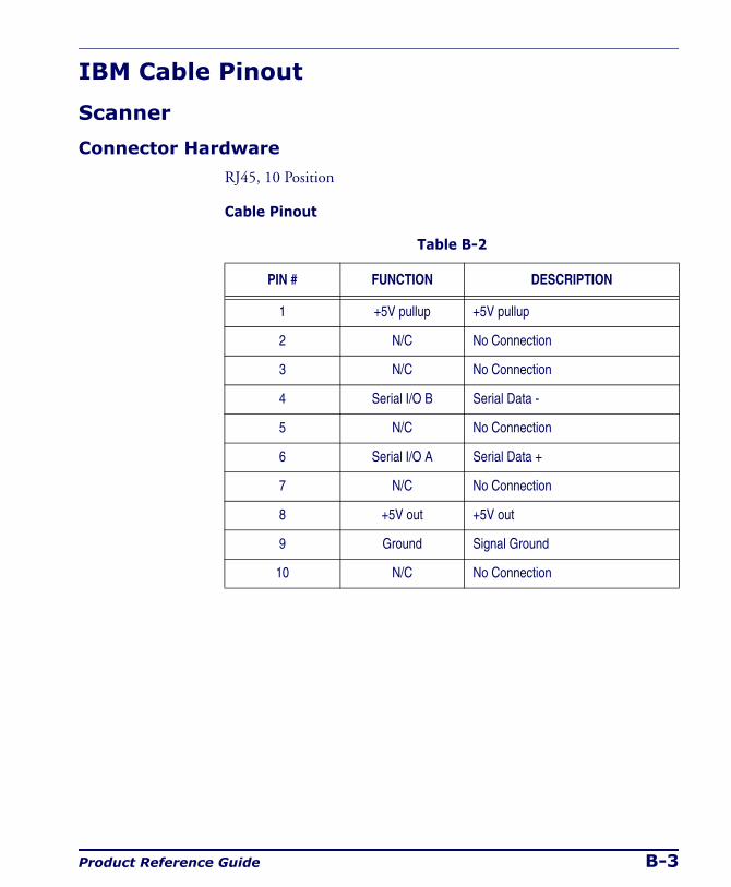
Product Reference Guide B-3
IBM Cable Pinout
Scanner
Connector Hardware
RJ45, 10 Position
Cable Pinout
Table B-2
PIN # FUNCTION DESCRIPTION
1 +5V pullup +5V pullup
2 N/C No Connection
3 N/C No Connection
4 Serial I/O B Serial Data -
5 N/C No Connection
6 Serial I/O A Serial Data +
7 N/C No Connection
8 +5V out +5V out
9 Ground Signal Ground
10 N/C No Connection
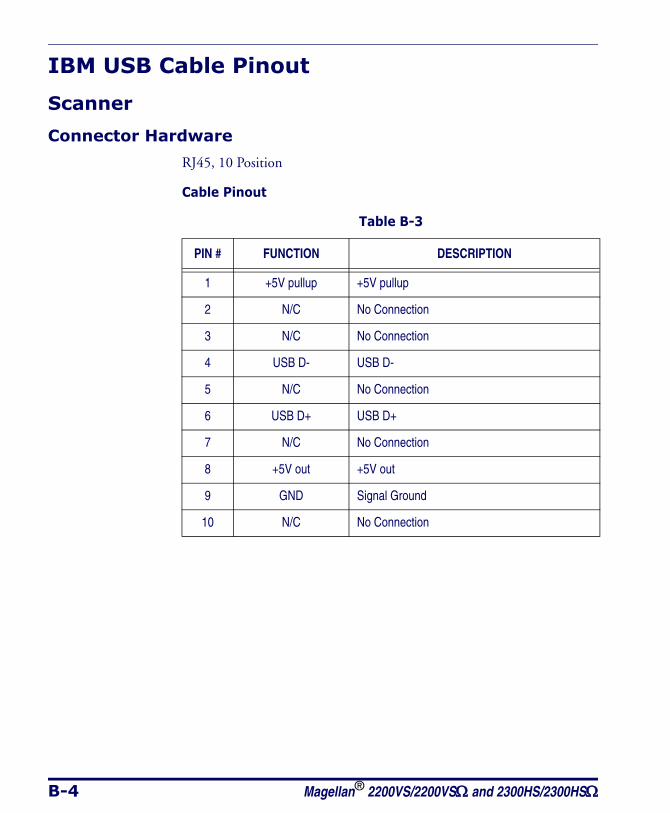
B-4 Magellan® 2200VS/2200VSΩ and 2300HS/2300HSΩ
IBM USB Cable Pinout
Scanner
Connector Hardware
RJ45, 10 Position
Cable Pinout
Table B-3
PIN # FUNCTION DESCRIPTION
1 +5V pullup +5V pullup
2 N/C No Connection
3 N/C No Connection
4 USB D- USB D-
5 N/C No Connection
6 USB D+ USB D+
7 N/C No Connection
8 +5V out +5V out
9 GND Signal Ground
10 N/C No Connection
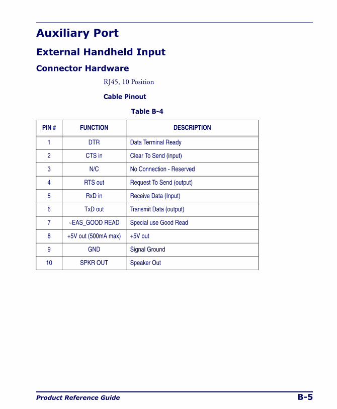
Product Reference Guide B-5
Auxiliary Port
External Handheld Input
Connector Hardware
RJ45, 10 Position
Cable Pinout
Table B-4
PIN # FUNCTION DESCRIPTION
1 DTR Data Terminal Ready
2 CTS in Clear To Send (input)
3 N/C No Connection - Reserved
4 RTS out Request To Send (output)
5 RxD in Receive Data (Input)
6 TxD out Transmit Data (output)
7 ~EAS_GOOD READ Special use Good Read
8 +5V out (500mA max) +5V out
9 GND Signal Ground
10 SPKR OUT Speaker Out

B-6 Magellan® 2200VS/2200VSΩ and 2300HS/2300HSΩ
NOTES
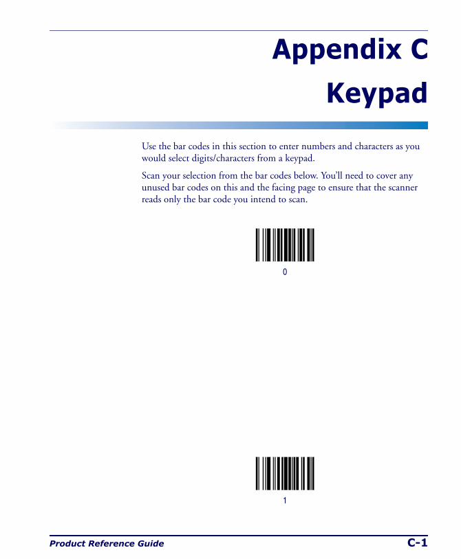
Product Reference Guide C-1
Appendix C
Keypad
Use the bar codes in this section to enter numbers and characters as you would select digits/characters from a keypad.
Scan your selection from the bar codes below. You’ll need to cover any unused bar codes on this and the facing page to ensure that the scanner reads only the bar code you intend to scan.
0
1
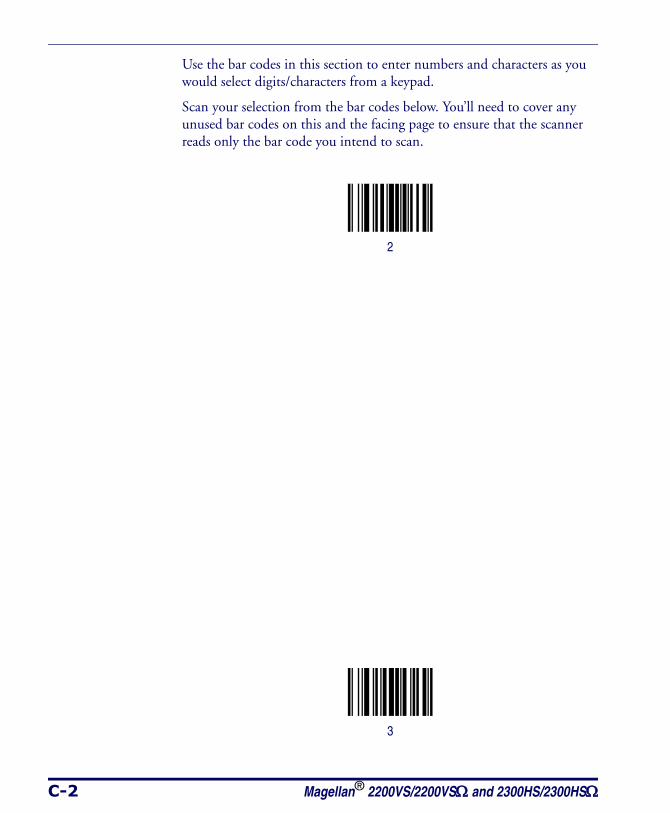
C-2 Magellan® 2200VS/2200VSΩ and 2300HS/2300HSΩ
Use the bar codes in this section to enter numbers and characters as you would select digits/characters from a keypad.
Scan your selection from the bar codes below. You’ll need to cover any unused bar codes on this and the facing page to ensure that the scanner reads only the bar code you intend to scan.
2
3
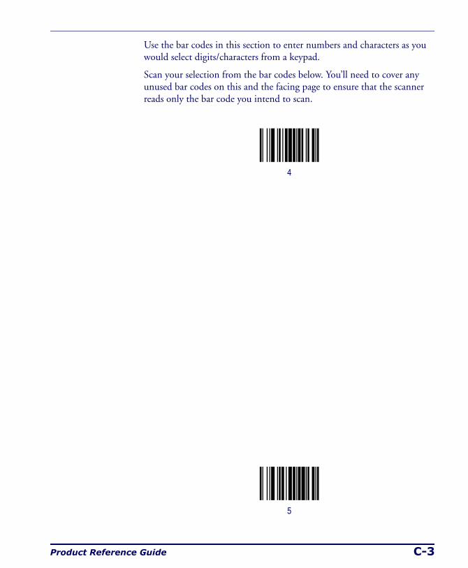
Product Reference Guide C-3
Use the bar codes in this section to enter numbers and characters as you would select digits/characters from a keypad.
Scan your selection from the bar codes below. You’ll need to cover any unused bar codes on this and the facing page to ensure that the scanner reads only the bar code you intend to scan.
4
5
C-4 Magellan® 2200VS/2200VSΩ and 2300HS/2300HSΩ
Use the bar codes in this section to enter numbers and characters as you would select digits/characters from a keypad.
Scan your selection from the bar codes below. You’ll need to cover any unused bar codes on this and the facing page to ensure that the scanner reads only the bar code you intend to scan.
6
7

Product Reference Guide C-5
Use the bar codes in this section to enter numbers and characters as you would select digits/characters from a keypad.
Scan your selection from the bar codes below. You’ll need to cover any unused bar codes on this and the facing page to ensure that the scanner reads only the bar code you intend to scan.
8
9
C-6 Magellan® 2200VS/2200VSΩ and 2300HS/2300HSΩ
Use the bar codes in this section to enter numbers and characters as you would select digits/characters from a keypad.
Scan your selection from the bar codes below. You’ll need to cover any unused bar codes on this and the facing page to ensure that the scanner reads only the bar code you intend to scan.
A
B

Product Reference Guide C-7
Use the bar codes in this section to enter numbers and characters as you would select digits/characters from a keypad.
Scan your selection from the bar codes below. You’ll need to cover any unused bar codes on this and the facing page to ensure that the scanner reads only the bar code you intend to scan.
C
D
C-8 Magellan® 2200VS/2200VSΩ and 2300HS/2300HSΩ
Use the bar codes in this section to enter numbers and characters as you would select digits/characters from a keypad.
Scan your selection from the bar codes below. You’ll need to cover any unused bar codes on this and the facing page to ensure that the scanner reads only the bar code you intend to scan.
E
F
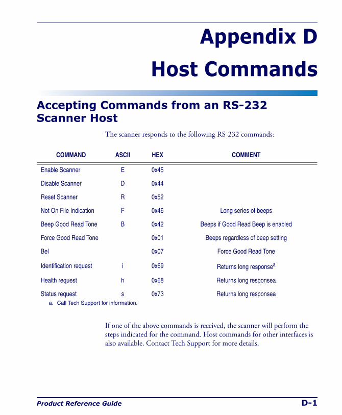
Product Reference Guide D-1
Appendix D
Host Commands
Accepting Commands from an RS-232 Scanner Host
The scanner responds to the following RS-232 commands:
If one of the above commands is received, the scanner will perform the steps indicated for the command. Host commands for other interfaces is also available. Contact Tech Support for more details.
COMMAND ASCII HEX COMMENT
Enable Scanner E 0x45
Disable Scanner D 0x44
Reset Scanner R 0x52
Not On File Indication F 0x46 Long series of beeps
Beep Good Read Tone B 0x42 Beeps if Good Read Beep is enabled
Force Good Read Tone 0x01 Beeps regardless of beep setting
Bel 0x07 Force Good Read Tone
Identification request i 0x69 Returns long responsea
Health request h 0x68 Returns long responsea
Status request s 0x73 Returns long responseaa. Call Tech Support for information.

D-2 Magellan® 2200VS/2200VSΩ and 2300HS/2300HSΩ
NOTES
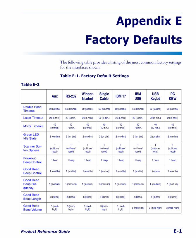
Product Reference Guide E-1
Appendix E
Factory Defaults
The following table provides a listing of the most common factory settings for the interfaces shown.
Table E-1. Factory Default Settings
Table E-2
Aux RS-232Wincor- Nixdorf
Single Cable
IBM 17IBM USB
USBKeybd
PC KBW
Double Read Timeout
60 (600ms) 60 (600ms) 60 (600ms) 60 (600ms) 60 (600ms) 60 (600ms) 60 (600ms) 60 (600ms)
Laser Timeout 20 (5 min.) 20 (5 min.) 20 (5 min.) 20 (5 min.) 20 (5 min.) 20 (5 min.) 20 (5 min.) 20 (5 min.)
Motor Timeout 40(10 min.)
40(10 min.)
40(10 min.)
40(10 min.)
40(10 min.)
40(10 min.)
40(10 min.)
40(10 min.)
Green LED Idle State
2 (on dim) 2 (on dim) 2 (on dim) 2 (on dim) 2 (on dim) 2 (on dim) 2 (on dim) 2 (on dim)
Scanner But-ton Options
1(vol/tone/
reset)
1(vol/tone/
reset)
1(vol/tone/
reset)
1(vol/tone/
reset)
1(vol/tone/
reset)
1(vol/tone/
reset)
1(vol/tone/
reset)
1(vol/tone/
reset)
Power-up Beep Control
1 beep 1 beep 1 beep 1 beep 1 beep 1 beep 1 beep 1 beep
Good Read Beep Control
1 (enable) 1 (enable) 1 (enable) 1 (enable) 1 (enable) 1 (enable) 1 (enable) 1 (enable)
Good Read Beep Fre-quency
1 (medium) 1 (medium) 1 (medium) 1 (medium) 1 (medium) 1 (medium) 1 (medium) 1 (medium)
Good Read Beep Length
8 (80ms) 8 (80ms) 8 (80ms) 8 (80ms) 8 (80ms) 8 (80ms) 8 (80ms) 8 (80ms)
Good Read Beep Volume
3 (med-high)
3 (med-high)
3 (med-high)
3 (med-high)
3 (med-high) 3 (med-high) 3 (med-high) 3 (med-high)
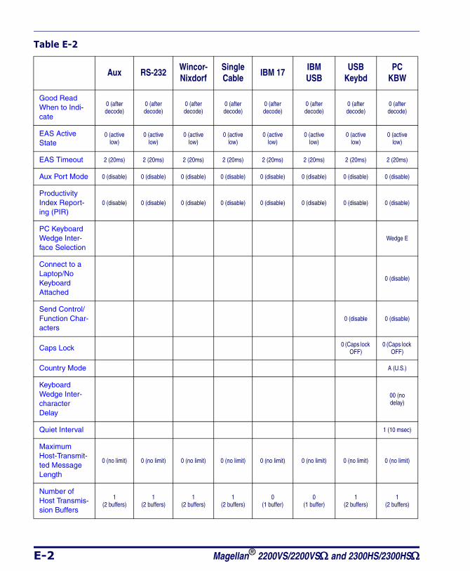
E-2 Magellan® 2200VS/2200VSΩ and 2300HS/2300HSΩ
Good Read When to Indi-cate
0 (after decode)
0 (after decode)
0 (after decode)
0 (after decode)
0 (after decode)
0 (after decode)
0 (after decode)
0 (after decode)
EAS Active State
0 (active low)
0 (active low)
0 (active low)
0 (active low)
0 (active low)
0 (active low)
0 (active low)
0 (active low)
EAS Timeout 2 (20ms) 2 (20ms) 2 (20ms) 2 (20ms) 2 (20ms) 2 (20ms) 2 (20ms) 2 (20ms)
Aux Port Mode 0 (disable) 0 (disable) 0 (disable) 0 (disable) 0 (disable) 0 (disable) 0 (disable) 0 (disable)
Productivity Index Report-ing (PIR)
0 (disable) 0 (disable) 0 (disable) 0 (disable) 0 (disable) 0 (disable) 0 (disable) 0 (disable)
PC Keyboard Wedge Inter-face Selection
Wedge E
Connect to a Laptop/No Keyboard Attached
0 (disable)
Send Control/Function Char-acters
0 (disable 0 (disable)
Caps Lock 0 (Caps lock OFF)
0 (Caps lock OFF)
Country Mode A (U.S.)
Keyboard Wedge Inter-character Delay
00 (no delay)
Quiet Interval 1 (10 msec)
Maximum Host-Transmit-ted Message Length
0 (no limit) 0 (no limit) 0 (no limit) 0 (no limit) 0 (no limit) 0 (no limit) 0 (no limit) 0 (no limit)
Number of Host Transmis-sion Buffers
1(2 buffers)
1(2 buffers)
1(2 buffers)
1(2 buffers)
0(1 buffer)
0(1 buffer)
1(2 buffers)
1(2 buffers)
Table E-2
Aux RS-232Wincor- Nixdorf
Single Cable
IBM 17IBM USB
USBKeybd
PC KBW
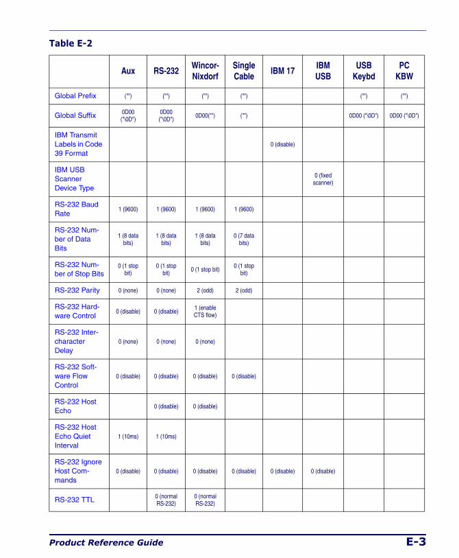
Product Reference Guide E-3
Global Prefix ("") ("") ("") ("") ("") ("")
Global Suffix 0D00 ("\0D")
0D00 ("\0D") 0D00("") ("") 0D00 ("\0D") 0D00 ("\0D")
IBM Transmit Labels in Code 39 Format
0 (disable)
IBM USB Scanner Device Type
0 (fixed scanner)
RS-232 Baud Rate
1 (9600) 1 (9600) 1 (9600) 1 (9600)
RS-232 Num-ber of Data Bits
1 (8 data bits)
1 (8 data bits)
1 (8 data bits)
0 (7 data bits)
RS-232 Num-ber of Stop Bits
0 (1 stop bit)
0 (1 stop bit) 0 (1 stop bit) 0 (1 stop
bit)
RS-232 Parity 0 (none) 0 (none) 2 (odd) 2 (odd)
RS-232 Hard-ware Control
0 (disable) 0 (disable) 1 (enable CTS flow)
RS-232 Inter-character Delay
0 (none) 0 (none) 0 (none)
RS-232 Soft-ware Flow Control
0 (disable) 0 (disable) 0 (disable) 0 (disable)
RS-232 Host Echo
0 (disable) 0 (disable)
RS-232 Host Echo Quiet Interval
1 (10ms) 1 (10ms)
RS-232 Ignore Host Com-mands
0 (disable) 0 (disable) 0 (disable) 0 (disable) 0 (disable) 0 (disable)
RS-232 TTL 0 (normal RS-232)
0 (normal RS-232)
Table E-2
Aux RS-232Wincor- Nixdorf
Single Cable
IBM 17IBM USB
USBKeybd
PC KBW
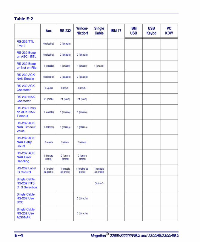
E-4 Magellan® 2200VS/2200VSΩ and 2300HS/2300HSΩ
RS-232 TTL Invert
0 (disable) 0 (disable)
RS-232 Beep on ASCII BEL
0 (disable) 0 (disable) 0 (disable)
RS-232 Beep on Not on File
1 (enable) 1 (enable) 1 (enable) 1 (enable)
RS-232 ACK NAK Enable
0 (disable) 0 (disable) 0 (disable)
RS-232 ACK Character
6 (ACK) 6 (ACK) 6 (ACK)
RS-232 NAK Character
21 (NAK) 21 (NAK) 21 (NAK)
RS-232 Retry on ACK NAK Timeout
1 (enable) 1 (enable) 1 (enable)
RS-232 ACK NAK Timeout Value
1 (200ms) 1 (200ms) 1 (200ms)
RS-232 ACK NAK Retry Count
3 resets 3 resets 3 resets
RS-232 ACK NAK Error Handling
0 (ignore errors)
0 (ignore errors)
0 (ignore errors)
RS-232 Label ID Control
1 (enable as prefix)
1 (enable as prefix)
1 (enable as prefix)
1 (enable as prefix)
Single Cable RS-232 RTS CTS Selection
Option 5
Single Cable RS-232 Use BCC
0 (disable)
Single Cable RS-232 Use ACK/NAK
0 (disable)
Table E-2
Aux RS-232Wincor- Nixdorf
Single Cable
IBM 17IBM USB
USBKeybd
PC KBW
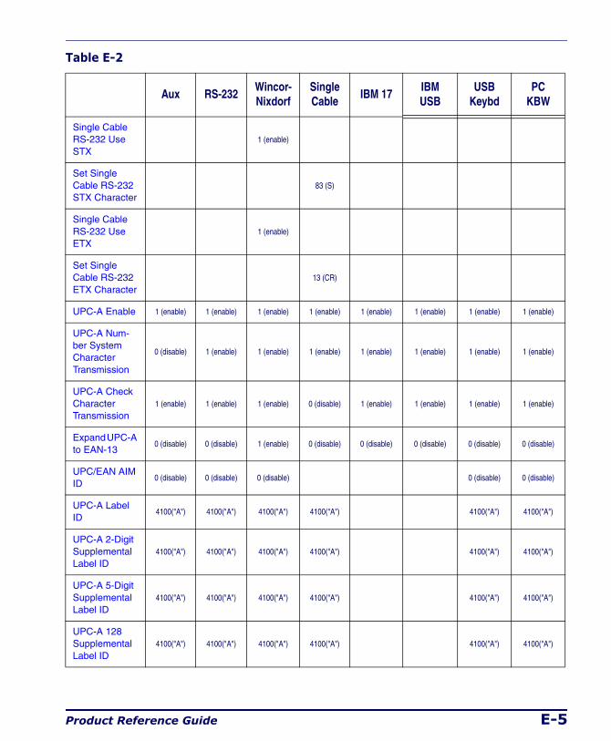
Product Reference Guide E-5
Single Cable RS-232 Use STX
1 (enable)
Set Single Cable RS-232 STX Character
83 (S)
Single Cable RS-232 Use ETX
1 (enable)
Set Single Cable RS-232 ETX Character
13 (CR)
UPC-A Enable 1 (enable) 1 (enable) 1 (enable) 1 (enable) 1 (enable) 1 (enable) 1 (enable) 1 (enable)
UPC-A Num-ber System Character Transmission
0 (disable) 1 (enable) 1 (enable) 1 (enable) 1 (enable) 1 (enable) 1 (enable) 1 (enable)
UPC-A Check Character Transmission
1 (enable) 1 (enable) 1 (enable) 0 (disable) 1 (enable) 1 (enable) 1 (enable) 1 (enable)
Expand UPC-A to EAN-13
0 (disable) 0 (disable) 1 (enable) 0 (disable) 0 (disable) 0 (disable) 0 (disable) 0 (disable)
UPC/EAN AIM ID
0 (disable) 0 (disable) 0 (disable) 0 (disable) 0 (disable)
UPC-A Label ID
4100("A") 4100("A") 4100("A") 4100("A") 4100("A") 4100("A")
UPC-A 2-Digit Supplemental Label ID
4100("A") 4100("A") 4100("A") 4100("A") 4100("A") 4100("A")
UPC-A 5-Digit Supplemental Label ID
4100("A") 4100("A") 4100("A") 4100("A") 4100("A") 4100("A")
UPC-A 128 Supplemental Label ID
4100("A") 4100("A") 4100("A") 4100("A") 4100("A") 4100("A")
Table E-2
Aux RS-232Wincor- Nixdorf
Single Cable
IBM 17IBM USB
USBKeybd
PC KBW
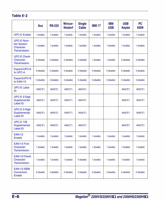
E-6 Magellan® 2200VS/2200VSΩ and 2300HS/2300HSΩ
UPC-E Enable 1 (enable) 1 (enable) 1 (enable) 1 (enable) 1 (enable) 1 (enable) 1 (enable) 1 (enable)
UPC-E Num-ber System Character Transmission
1 (enable) 1 (enable) 1 (enable) 1 (enable) 1 (enable) 1 (enable) 1 (enable) 1 (enable)
UPC-E Check Character Transmission
0 (disable) 0 (disable) 0 (disable) 0 (disable) 1 (enable) 1 (enable) 0 (disable) 0 (disable)
Expand UPC-E to UPC-A
0 (disable) 0 (disable) 0 (disable) 0 (disable) 0 (disable) 0 (disable) 0 (disable) 0 (disable)
Expand UPC-E to EAN-13
0 (disable) 0 (disable) 0 (disable) 0 (disable) 0 (disable) 0 (disable) 0 (disable) 0 (disable)
UPC-E Label ID
4500("E") 4500("E") 4300("C") 4500("E") 4500("E") 4500("E")
UPC-E 2-Digit Supplemental Label ID
4500("E") 4500("E") 4300("C") 4500("E") 4500("E") 4500("E")
UPC-E 5-Digit Supplemental Label ID
4500("E") 4500("E") 4300("C") 4500("E") 4500("E") 4500("E")
UPC-E 128 Supplemental Label ID
4500("E") 4500("E") 4300("C") 4500("E") 4500("E") 4500("E")
EAN-13 Enable
1 (enable) 1 (enable) 1 (enable) 1 (enable) 1 (enable) 1 (enable) 1 (enable) 1 (enable)
EAN-13 First Character Transmission
1 (enable) 1 (enable) 1 (enable) 1 (enable) 1 (enable) 1 (enable) 1 (enable) 1 (enable)
EAN-13 Check Character Transmission
1 (enable) 1 (enable) 1 (enable) 0 (disable) 1 (enable) 1 (enable) 1 (enable) 1 (enable)
EAN-13 ISBN Conversion Enable
0 (disable) 0 (disable) 0 (disable) 0 (disable) 0 (disable) 0 (disable) 0 (disable) 0 (disable)
Table E-2
Aux RS-232Wincor- Nixdorf
Single Cable
IBM 17IBM USB
USBKeybd
PC KBW
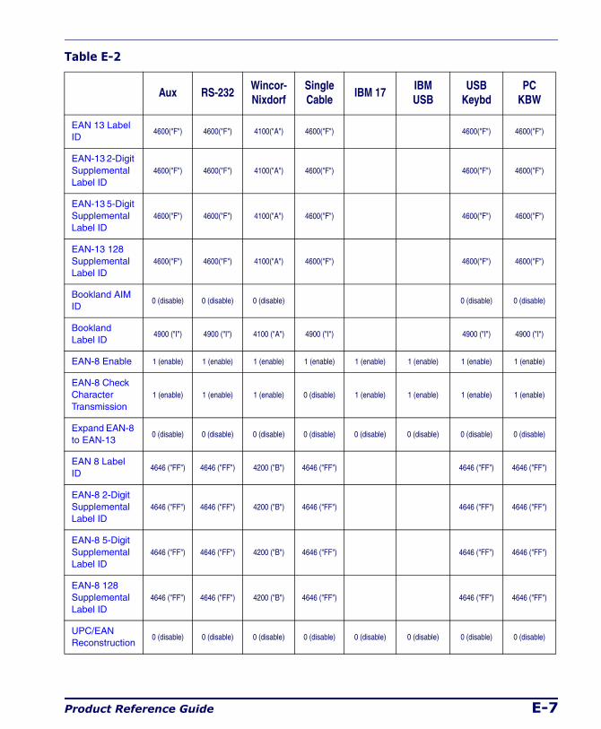
Product Reference Guide E-7
EAN 13 Label ID
4600("F") 4600("F") 4100("A") 4600("F") 4600("F") 4600("F")
EAN-13 2-Digit Supplemental Label ID
4600("F") 4600("F") 4100("A") 4600("F") 4600("F") 4600("F")
EAN-13 5-Digit Supplemental Label ID
4600("F") 4600("F") 4100("A") 4600("F") 4600("F") 4600("F")
EAN-13 128 Supplemental Label ID
4600("F") 4600("F") 4100("A") 4600("F") 4600("F") 4600("F")
Bookland AIM ID
0 (disable) 0 (disable) 0 (disable) 0 (disable) 0 (disable)
Bookland Label ID
4900 ("I") 4900 ("I") 4100 ("A") 4900 ("I") 4900 ("I") 4900 ("I")
EAN-8 Enable 1 (enable) 1 (enable) 1 (enable) 1 (enable) 1 (enable) 1 (enable) 1 (enable) 1 (enable)
EAN-8 Check Character Transmission
1 (enable) 1 (enable) 1 (enable) 0 (disable) 1 (enable) 1 (enable) 1 (enable) 1 (enable)
Expand EAN-8 to EAN-13
0 (disable) 0 (disable) 0 (disable) 0 (disable) 0 (disable) 0 (disable) 0 (disable) 0 (disable)
EAN 8 Label ID
4646 ("FF") 4646 ("FF") 4200 ("B") 4646 ("FF") 4646 ("FF") 4646 ("FF")
EAN-8 2-Digit Supplemental Label ID
4646 ("FF") 4646 ("FF") 4200 ("B") 4646 ("FF") 4646 ("FF") 4646 ("FF")
EAN-8 5-Digit Supplemental Label ID
4646 ("FF") 4646 ("FF") 4200 ("B") 4646 ("FF") 4646 ("FF") 4646 ("FF")
EAN-8 128 Supplemental Label ID
4646 ("FF") 4646 ("FF") 4200 ("B") 4646 ("FF") 4646 ("FF") 4646 ("FF")
UPC/EAN Reconstruction
0 (disable) 0 (disable) 0 (disable) 0 (disable) 0 (disable) 0 (disable) 0 (disable) 0 (disable)
Table E-2
Aux RS-232Wincor- Nixdorf
Single Cable
IBM 17IBM USB
USBKeybd
PC KBW
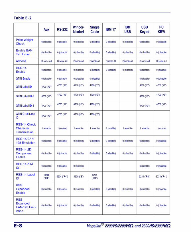
E-8 Magellan® 2200VS/2200VSΩ and 2300HS/2300HSΩ
Price Weight Check
0 (disable) 0 (disable) 0 (disable) 0 (disable) 0 (disable) 0 (disable) 0 (disable) 0 (disable)
Enable EAN Two Label
0 (disable) 0 (disable) 0 (disable) 0 (disable) 0 (disable) 0 (disable) 0 (disable) 0 (disable)
Addons Disable All Disable All Disable All Disable All Disable All Disable All Disable All Disable All
RSS-14 Enable
0 (disable) 0 (disable) 0 (disable) 0 (disable) 0 (disable) 0 (disable) 0 (disable) 0 (disable)
GTIN Enable 0 (disable) 0 (disable) 0 (disable) 0 (disable) 0 (disable) 0 (disable)
GTIN Label ID 4700 (“G”) 4700 (“G”) 4700 (“G”) 4700 (“G”) 4700 (“G”) 4700 (“G”)
GTIN Label ID-2 4700 (“G”) 4700 (“G”) 4700 (“G”) 4700 (“G”) 4700 (“G”) 4700 (“G”)
GTIN Label ID-5 4700 (“G”) 4700 (“G”) 4700 (“G”) 4700 (“G”) 4700 (“G”) 4700 (“G”)
GTIN C128 Label ID
4700 (“G”) 4700 (“G”) 4700 (“G”) 4700 (“G”)
RSS-14 Check Character Transmission
1 (enable) 1 (enable) 1 (enable) 1 (enable) 1 (enable) 1 (enable) 1 (enable) 1 (enable)
RSS-14/EAN-128 Emulation
0 (disable) 0 (disable) 0 (disable) 0 (disable) 0 (disable) 0 (disable) 0 (disable) 0 (disable)
RSS-14 2D Component Enable
0 (disable) 0 (disable) 0 (disable) 0 (disable) 0 (disable) 0 (disable) 0 (disable) 0 (disable)
RSS-14 AIM ID
0 (disable) 0 (disable) 0 (disable) 0 (disable) 0 (disable)
RSS-14 Label ID
5234 ("R4") 5234 ("R4") 4500 ("E") 5234
("R4") 5234 ("R4") 5234 ("R4")
RSS Expanded Enable
0 (disable) 0 (disable) 0 (disable) 0 (disable) 0 (disable) 0 (disable) 0 (disable) 0 (disable)
RSS Expanded EAN-128 Emu-lation
0 (disable) 0 (disable) 0 (disable) 0 (disable) 0 (disable) 0 (disable) 0 (disable) 0 (disable)
Table E-2
Aux RS-232Wincor- Nixdorf
Single Cable
IBM 17IBM USB
USBKeybd
PC KBW
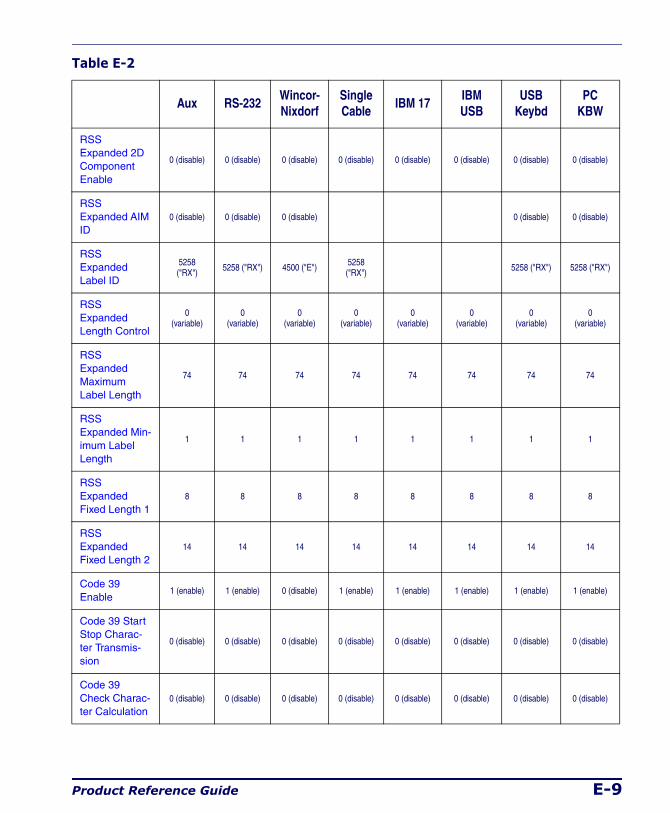
Product Reference Guide E-9
RSS Expanded 2D Component Enable
0 (disable) 0 (disable) 0 (disable) 0 (disable) 0 (disable) 0 (disable) 0 (disable) 0 (disable)
RSS Expanded AIM ID
0 (disable) 0 (disable) 0 (disable) 0 (disable) 0 (disable)
RSS Expanded Label ID
5258 ("RX") 5258 ("RX") 4500 ("E") 5258
("RX") 5258 ("RX") 5258 ("RX")
RSS Expanded Length Control
0(variable)
0(variable)
0(variable)
0(variable)
0(variable)
0(variable)
0(variable)
0(variable)
RSS Expanded Maximum Label Length
74 74 74 74 74 74 74 74
RSS Expanded Min-imum Label Length
1 1 1 1 1 1 1 1
RSS Expanded Fixed Length 1
8 8 8 8 8 8 8 8
RSS Expanded Fixed Length 2
14 14 14 14 14 14 14 14
Code 39 Enable
1 (enable) 1 (enable) 0 (disable) 1 (enable) 1 (enable) 1 (enable) 1 (enable) 1 (enable)
Code 39 Start Stop Charac-ter Transmis-sion
0 (disable) 0 (disable) 0 (disable) 0 (disable) 0 (disable) 0 (disable) 0 (disable) 0 (disable)
Code 39 Check Charac-ter Calculation
0 (disable) 0 (disable) 0 (disable) 0 (disable) 0 (disable) 0 (disable) 0 (disable) 0 (disable)
Table E-2
Aux RS-232Wincor- Nixdorf
Single Cable
IBM 17IBM USB
USBKeybd
PC KBW
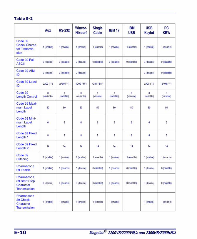
E-10 Magellan® 2200VS/2200VSΩ and 2300HS/2300HSΩ
Code 39 Check Charac-ter Transmis-sion
1 (enable) 1 (enable) 1 (enable) 1 (enable) 1 (enable) 1 (enable) 1 (enable) 1 (enable)
Code 39 Full ASCII
0 (disable) 0 (disable) 0 (disable) 0 (disable) 0 (disable) 0 (disable) 0 (disable) 0 (disable)
Code 39 AIM ID
0 (disable) 0 (disable) 0 (disable) 0 (disable) 0 (disable)
Code 39 Label ID
2A00 ("*") 2A00 ("*") 4D00 ("M") 4231 ("B1") 2A00 ("*") 2A00 ("*")
Code 39 Length Control
0(variable)
0(variable)
0(variable)
0(variable)
0(variable)
0(variable)
0(variable)
0(variable)
Code 39 Maxi-mum Label Length
50 50 50 50 50 50 50 50
Code 39 Mini-mum Label Length
6 6 6 6 6 6 6 6
Code 39 Fixed Length 1
8 8 8 8 8 8 8 8
Code 39 Fixed Length 2
14 14 14 14 14 14 14 14
Code 39 Stitching
1 (enable) 1 (enable) 1 (enable) 1 (enable) 1 (enable) 1 (enable) 1 (enable) 1 (enable)
Pharmacode 39 Enable
1 (enable) 0 (disable) 0 (disable) 0 (disable) 0 (disable) 0 (disable) 0 (disable) 0 (disable)
Pharmacode 39 Start Stop Character Transmission
0 (disable) 0 (disable) 0 (disable) 0 (disable) 0 (disable) 0 (disable) 0 (disable) 0 (disable)
Pharmacode 39 Check Character Transmission
1 (enable) 1 (enable) 1 (enable) 1 (enable) 1 (enable) 1 (enable) 1 (enable)
Table E-2
Aux RS-232Wincor- Nixdorf
Single Cable
IBM 17IBM USB
USBKeybd
PC KBW
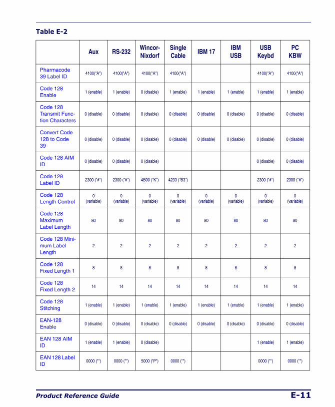
Product Reference Guide E-11
Pharmacode 39 Label ID
4100("A") 4100("A") 4100("A") 4100("A") 4100("A") 4100("A")
Code 128 Enable
1 (enable) 1 (enable) 0 (disable) 1 (enable) 1 (enable) 1 (enable) 1 (enable) 1 (enable)
Code 128 Transmit Func-tion Characters
0 (disable) 0 (disable) 0 (disable) 0 (disable) 0 (disable) 0 (disable) 0 (disable) 0 (disable)
Convert Code 128 to Code 39
0 (disable) 0 (disable) 0 (disable) 0 (disable) 0 (disable) 0 (disable) 0 (disable) 0 (disable)
Code 128 AIM ID
0 (disable) 0 (disable) 0 (disable) 0 (disable) 0 (disable)
Code 128 Label ID
2300 ("#") 2300 ("#") 4B00 ("K") 4233 ("B3") 2300 ("#") 2300 ("#")
Code 128 Length Control
0(variable)
0(variable)
0(variable)
0(variable)
0(variable)
0(variable)
0(variable)
0(variable)
Code 128 Maximum Label Length
80 80 80 80 80 80 80 80
Code 128 Mini-mum Label Length
2 2 2 2 2 2 2 2
Code 128 Fixed Length 1
8 8 8 8 8 8 8 8
Code 128 Fixed Length 2
14 14 14 14 14 14 14 14
Code 128 Stitching
1 (enable) 1 (enable) 1 (enable) 1 (enable) 1 (enable) 1 (enable) 1 (enable) 1 (enable)
EAN-128 Enable
0 (disable) 0 (disable) 0 (disable) 0 (disable) 0 (disable) 0 (disable) 0 (disable) 0 (disable)
EAN 128 AIM ID
1 (enable) 1 (enable) 0 (disable) 1 (enable) 1 (enable)
EAN 128 Label ID
0000 ("") 0000 ("") 5000 ("P") 0000 ("") 0000 ("") 0000 ("")
Table E-2
Aux RS-232Wincor- Nixdorf
Single Cable
IBM 17IBM USB
USBKeybd
PC KBW
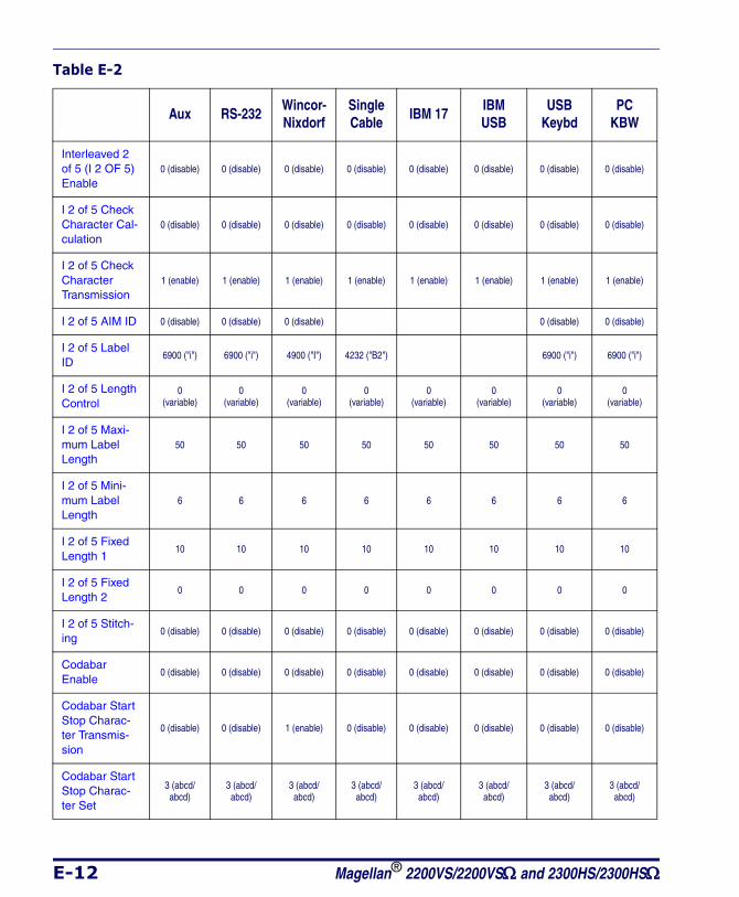
E-12 Magellan® 2200VS/2200VSΩ and 2300HS/2300HSΩ
Interleaved 2 of 5 (I 2 OF 5) Enable
0 (disable) 0 (disable) 0 (disable) 0 (disable) 0 (disable) 0 (disable) 0 (disable) 0 (disable)
I 2 of 5 Check Character Cal-culation
0 (disable) 0 (disable) 0 (disable) 0 (disable) 0 (disable) 0 (disable) 0 (disable) 0 (disable)
I 2 of 5 Check Character Transmission
1 (enable) 1 (enable) 1 (enable) 1 (enable) 1 (enable) 1 (enable) 1 (enable) 1 (enable)
I 2 of 5 AIM ID 0 (disable) 0 (disable) 0 (disable) 0 (disable) 0 (disable)
I 2 of 5 Label ID
6900 ("i") 6900 ("i") 4900 ("I") 4232 ("B2") 6900 ("i") 6900 ("i")
I 2 of 5 Length Control
0(variable)
0(variable)
0(variable)
0(variable)
0(variable)
0(variable)
0(variable)
0(variable)
I 2 of 5 Maxi-mum Label Length
50 50 50 50 50 50 50 50
I 2 of 5 Mini-mum Label Length
6 6 6 6 6 6 6 6
I 2 of 5 Fixed Length 1
10 10 10 10 10 10 10 10
I 2 of 5 Fixed Length 2
0 0 0 0 0 0 0 0
I 2 of 5 Stitch-ing
0 (disable) 0 (disable) 0 (disable) 0 (disable) 0 (disable) 0 (disable) 0 (disable) 0 (disable)
Codabar Enable
0 (disable) 0 (disable) 0 (disable) 0 (disable) 0 (disable) 0 (disable) 0 (disable) 0 (disable)
Codabar Start Stop Charac-ter Transmis-sion
0 (disable) 0 (disable) 1 (enable) 0 (disable) 0 (disable) 0 (disable) 0 (disable) 0 (disable)
Codabar Start Stop Charac-ter Set
3 (abcd/abcd)
3 (abcd/abcd)
3 (abcd/abcd)
3 (abcd/abcd)
3 (abcd/abcd)
3 (abcd/abcd)
3 (abcd/abcd)
3 (abcd/abcd)
Table E-2
Aux RS-232Wincor- Nixdorf
Single Cable
IBM 17IBM USB
USBKeybd
PC KBW
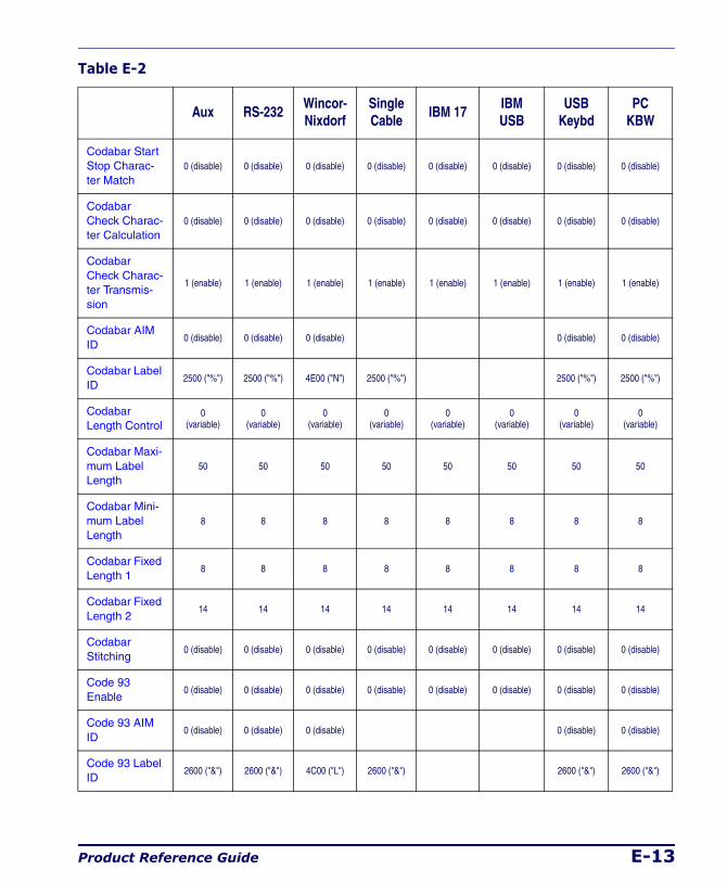
Product Reference Guide E-13
Codabar Start Stop Charac-ter Match
0 (disable) 0 (disable) 0 (disable) 0 (disable) 0 (disable) 0 (disable) 0 (disable) 0 (disable)
Codabar Check Charac-ter Calculation
0 (disable) 0 (disable) 0 (disable) 0 (disable) 0 (disable) 0 (disable) 0 (disable) 0 (disable)
Codabar Check Charac-ter Transmis-sion
1 (enable) 1 (enable) 1 (enable) 1 (enable) 1 (enable) 1 (enable) 1 (enable) 1 (enable)
Codabar AIM ID
0 (disable) 0 (disable) 0 (disable) 0 (disable) 0 (disable)
Codabar Label ID
2500 ("%") 2500 ("%") 4E00 ("N") 2500 ("%") 2500 ("%") 2500 ("%")
Codabar Length Control
0(variable)
0(variable)
0(variable)
0(variable)
0(variable)
0(variable)
0(variable)
0(variable)
Codabar Maxi-mum Label Length
50 50 50 50 50 50 50 50
Codabar Mini-mum Label Length
8 8 8 8 8 8 8 8
Codabar Fixed Length 1
8 8 8 8 8 8 8 8
Codabar Fixed Length 2
14 14 14 14 14 14 14 14
Codabar Stitching
0 (disable) 0 (disable) 0 (disable) 0 (disable) 0 (disable) 0 (disable) 0 (disable) 0 (disable)
Code 93 Enable
0 (disable) 0 (disable) 0 (disable) 0 (disable) 0 (disable) 0 (disable) 0 (disable) 0 (disable)
Code 93 AIM ID
0 (disable) 0 (disable) 0 (disable) 0 (disable) 0 (disable)
Code 93 Label ID
2600 ("&") 2600 ("&") 4C00 ("L") 2600 ("&") 2600 ("&") 2600 ("&")
Table E-2
Aux RS-232Wincor- Nixdorf
Single Cable
IBM 17IBM USB
USBKeybd
PC KBW
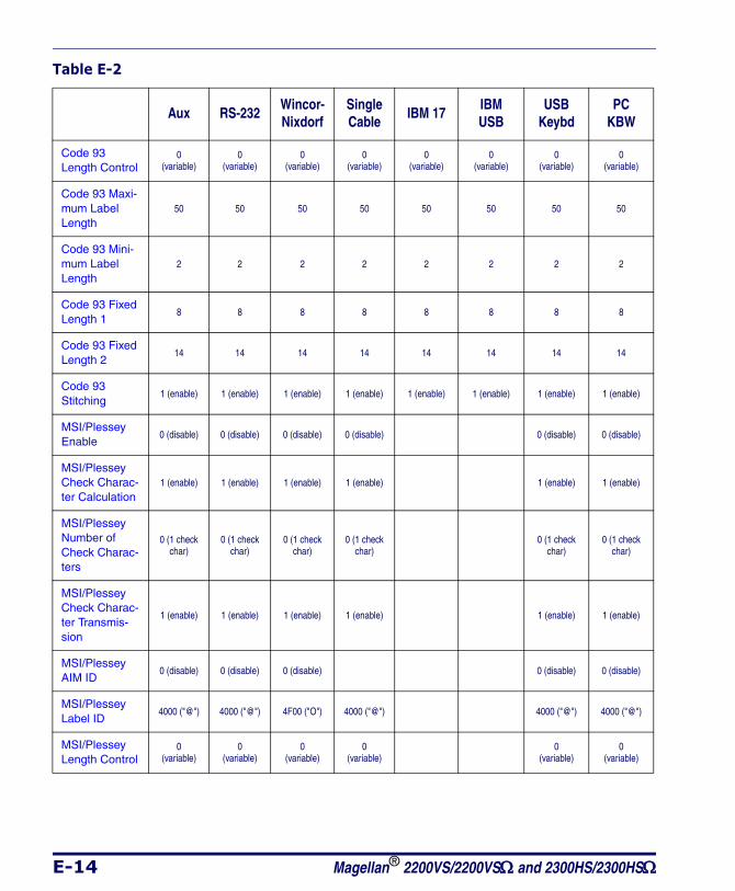
E-14 Magellan® 2200VS/2200VSΩ and 2300HS/2300HSΩ
Code 93 Length Control
0(variable)
0(variable)
0(variable)
0(variable)
0(variable)
0(variable)
0(variable)
0(variable)
Code 93 Maxi-mum Label Length
50 50 50 50 50 50 50 50
Code 93 Mini-mum Label Length
2 2 2 2 2 2 2 2
Code 93 Fixed Length 1
8 8 8 8 8 8 8 8
Code 93 Fixed Length 2
14 14 14 14 14 14 14 14
Code 93 Stitching
1 (enable) 1 (enable) 1 (enable) 1 (enable) 1 (enable) 1 (enable) 1 (enable) 1 (enable)
MSI/Plessey Enable
0 (disable) 0 (disable) 0 (disable) 0 (disable) 0 (disable) 0 (disable)
MSI/Plessey Check Charac-ter Calculation
1 (enable) 1 (enable) 1 (enable) 1 (enable) 1 (enable) 1 (enable)
MSI/Plessey Number of Check Charac-ters
0 (1 check char)
0 (1 check char)
0 (1 check char)
0 (1 check char)
0 (1 check char)
0 (1 check char)
MSI/Plessey Check Charac-ter Transmis-sion
1 (enable) 1 (enable) 1 (enable) 1 (enable) 1 (enable) 1 (enable)
MSI/Plessey AIM ID
0 (disable) 0 (disable) 0 (disable) 0 (disable) 0 (disable)
MSI/Plessey Label ID
4000 ("@") 4000 ("@") 4F00 ("O") 4000 ("@") 4000 ("@") 4000 ("@")
MSI/Plessey Length Control
0(variable)
0(variable)
0(variable)
0(variable)
0(variable)
0(variable)
Table E-2
Aux RS-232Wincor- Nixdorf
Single Cable
IBM 17IBM USB
USBKeybd
PC KBW
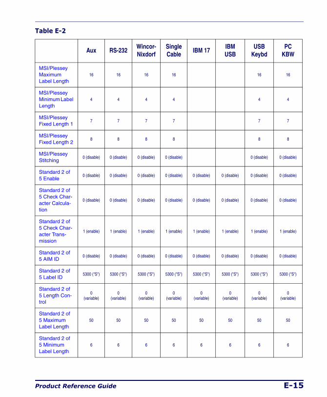
Product Reference Guide E-15
MSI/Plessey Maximum Label Length
16 16 16 16 16 16
MSI/Plessey Minimum Label Length
4 4 4 4 4 4
MSI/Plessey Fixed Length 1
7 7 7 7 7 7
MSI/Plessey Fixed Length 2
8 8 8 8 8 8
MSI/Plessey Stitching
0 (disable) 0 (disable) 0 (disable) 0 (disable) 0 (disable) 0 (disable)
Standard 2 of 5 Enable
0 (disable) 0 (disable) 0 (disable) 0 (disable) 0 (disable) 0 (disable) 0 (disable) 0 (disable)
Standard 2 of 5 Check Char-acter Calcula-tion
0 (disable) 0 (disable) 0 (disable) 0 (disable) 0 (disable) 0 (disable) 0 (disable) 0 (disable)
Standard 2 of 5 Check Char-acter Trans-mission
1 (enable) 1 (enable) 1 (enable) 1 (enable) 1 (enable) 1 (enable) 1 (enable) 1 (enable)
Standard 2 of 5 AIM ID
0 (disable) 0 (disable) 0 (disable) 0 (disable) 0 (disable) 0 (disable) 0 (disable) 0 (disable)
Standard 2 of 5 Label ID
5300 ("S") 5300 ("S") 5300 ("S") 5300 ("S") 5300 ("S") 5300 ("S") 5300 ("S") 5300 ("S")
Standard 2 of 5 Length Con-trol
0(variable)
0(variable)
0(variable)
0(variable)
0(variable)
0(variable)
0(variable)
0(variable)
Standard 2 of 5 Maximum Label Length
50 50 50 50 50 50 50 50
Standard 2 of 5 Minimum Label Length
6 6 6 6 6 6 6 6
Table E-2
Aux RS-232Wincor- Nixdorf
Single Cable
IBM 17IBM USB
USBKeybd
PC KBW
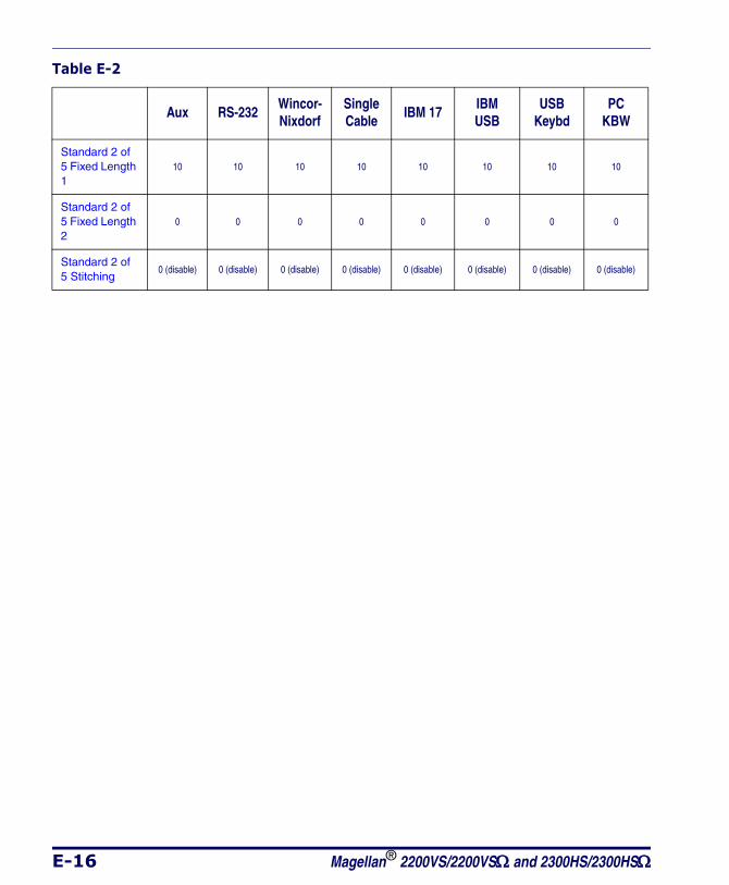
E-16 Magellan® 2200VS/2200VSΩ and 2300HS/2300HSΩ
Standard 2 of 5 Fixed Length 1
10 10 10 10 10 10 10 10
Standard 2 of 5 Fixed Length 2
0 0 0 0 0 0 0 0
Standard 2 of 5 Stitching
0 (disable) 0 (disable) 0 (disable) 0 (disable) 0 (disable) 0 (disable) 0 (disable) 0 (disable)
Table E-2
Aux RS-232Wincor- Nixdorf
Single Cable
IBM 17IBM USB
USBKeybd
PC KBW

Product Reference Guide F-1
Appendix F
Handheld Data Format Requirements
This appendix provides application notes to describe the general format of data that can be accepted by the scanner through the auxiliary port as transmitted from a handheld scanner.
Handheld Data Format Requirements General• 9600 bps, 8 data bits, 1 stop bit, no parity.
• RTS is used to "bracket" the data received from the handheld: RTS must be asserted high during data transmission, and de-asserted after label transmission is complete. No other flow control mecha-nisms are required or supported.
• Symbologies requiring fixed lengths (UPC/EAN) will enforce length requirements for validation of the label.
• Handheld will be required to transmit start and stop characters for Codabar and Code 39 labels.
• Appropriate industrial length requirements will be enforced (if con-figured) for validation of the label.
• Maximum label lengths will be enforced for label validation (i.e. labels longer than the maximum label size will not be validated).
• Standard PSC formats generally use a single prefix character. The specific formats are provided below.
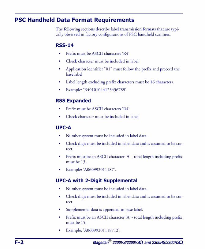
F-2 Magellan® 2200VS/2200VSΩ and 2300HS/2300HSΩ
PSC Handheld Data Format RequirementsThe following sections describe label transmission formats that are typi-cally observed in factory configurations of PSC handheld scanners.
RSS-14
• Prefix must be ASCII characters ‘R4’
• Check character must be included in label
• Application identifier “01” must follow the prefix and preceed the base label
• Label length excluding prefix characters must be 16 characters.
• Example: ‘R40101044123456789’
RSS Expanded
• Prefix must be ASCII characters ‘R4’
• Check character must be included in label
UPC-A
• Number system must be included in label data.
• Check digit must be included in label data and is assumed to be cor-rect.
• Prefix must be an ASCII character 'A' - total length including prefix must be 13.
• Example: 'A060992011187'.
UPC-A with 2-Digit Supplemental
• Number system must be included in label data.
• Check digit must be included in label data and is assumed to be cor-rect.
• Supplemental data is appended to base label.
• Prefix must be an ASCII character 'A' - total length including prefix must be 15.
• Example: 'A06099201118712'.
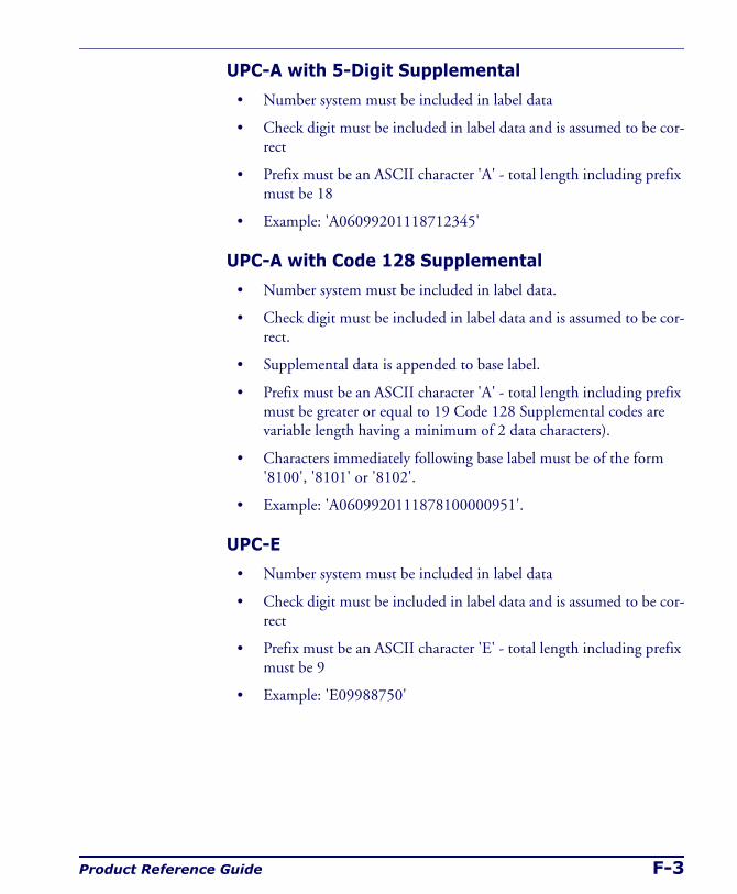
Product Reference Guide F-3
UPC-A with 5-Digit Supplemental
• Number system must be included in label data
• Check digit must be included in label data and is assumed to be cor-rect
• Prefix must be an ASCII character 'A' - total length including prefix must be 18
• Example: 'A06099201118712345'
UPC-A with Code 128 Supplemental
• Number system must be included in label data.
• Check digit must be included in label data and is assumed to be cor-rect.
• Supplemental data is appended to base label.
• Prefix must be an ASCII character 'A' - total length including prefix must be greater or equal to 19 Code 128 Supplemental codes are variable length having a minimum of 2 data characters).
• Characters immediately following base label must be of the form '8100', '8101' or '8102'.
• Example: 'A0609920111878100000951'.
UPC-E
• Number system must be included in label data
• Check digit must be included in label data and is assumed to be cor-rect
• Prefix must be an ASCII character 'E' - total length including prefix must be 9
• Example: 'E09988750'
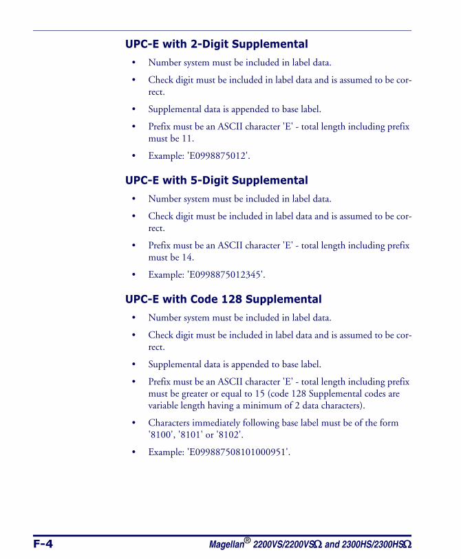
F-4 Magellan® 2200VS/2200VSΩ and 2300HS/2300HSΩ
UPC-E with 2-Digit Supplemental
• Number system must be included in label data.
• Check digit must be included in label data and is assumed to be cor-rect.
• Supplemental data is appended to base label.
• Prefix must be an ASCII character 'E' - total length including prefix must be 11.
• Example: 'E0998875012'.
UPC-E with 5-Digit Supplemental
• Number system must be included in label data.
• Check digit must be included in label data and is assumed to be cor-rect.
• Prefix must be an ASCII character 'E' - total length including prefix must be 14.
• Example: 'E0998875012345'.
UPC-E with Code 128 Supplemental
• Number system must be included in label data.
• Check digit must be included in label data and is assumed to be cor-rect.
• Supplemental data is appended to base label.
• Prefix must be an ASCII character 'E' - total length including prefix must be greater or equal to 15 (code 128 Supplemental codes are variable length having a minimum of 2 data characters).
• Characters immediately following base label must be of the form '8100', '8101' or '8102'.
• Example: 'E099887508101000951'.
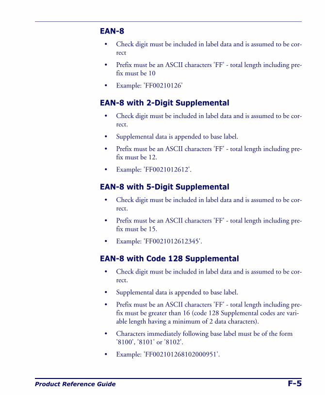
Product Reference Guide F-5
EAN-8
• Check digit must be included in label data and is assumed to be cor-rect
• Prefix must be an ASCII characters 'FF' - total length including pre-fix must be 10
• Example: 'FF00210126'
EAN-8 with 2-Digit Supplemental
• Check digit must be included in label data and is assumed to be cor-rect.
• Supplemental data is appended to base label.
• Prefix must be an ASCII characters 'FF' - total length including pre-fix must be 12.
• Example: 'FF0021012612'.
EAN-8 with 5-Digit Supplemental
• Check digit must be included in label data and is assumed to be cor-rect.
• Prefix must be an ASCII characters 'FF' - total length including pre-fix must be 15.
• Example: 'FF0021012612345'.
EAN-8 with Code 128 Supplemental
• Check digit must be included in label data and is assumed to be cor-rect.
• Supplemental data is appended to base label.
• Prefix must be an ASCII characters 'FF' - total length including pre-fix must be greater than 16 (code 128 Supplemental codes are vari-able length having a minimum of 2 data characters).
• Characters immediately following base label must be of the form '8100', '8101' or '8102'.
• Example: 'FF002101268102000951'.
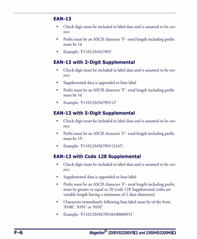
F-6 Magellan® 2200VS/2200VSΩ and 2300HS/2300HSΩ
EAN-13
• Check digit must be included in label data and is assumed to be cor-rect
• Prefix must be an ASCII character 'F'- total length including prefix must be 14
• Example: 'F1101234567891'
EAN-13 with 2-Digit Supplemental
• Check digit must be included in label data and is assumed to be cor-rect
• Supplemental data is appended to base label
• Prefix must be an ASCII character 'F'- total length including prefix must be 16
• Example: 'F110123456789112'
EAN-13 with 5-Digit Supplemental
• Check digit must be included in label data and is assumed to be cor-rect.
• Prefix must be an ASCII character 'F'- total length including prefix must be 19.
• Example: 'F110123456789112345'.
EAN-13 with Code 128 Supplemental
• Check digit must be included in label data and is assumed to be cor-rect
• Supplemental data is appended to base label
• Prefix must be an ASCII character 'F'- total length including prefix must be greater or equal to 20 (code 128 Supplemental codes are variable length having a minimum of 2 data characters)
• Characters immediately following base label must be of the form '8100', '8101' or '8102'
• Example: 'F11012345678918100000951'
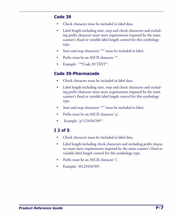
Product Reference Guide F-7
Code 39
• Check character must be included in label data.
• Label length including start, stop and check characters and exclud-ing prefix character must meet requirements imposed by the main scanner's fixed or variable label length control for this symbology type.
• Start and stop characters "*" must be included in label.
• Prefix must be an ASCII character '*'.
• Example : '**Code 39.TEST*'.
Code 39-Pharmacode
• Check character must be included in label data.
• Label length including start, stop and check characters and exclud-ing prefix character must meet requirements imposed by the main scanner's fixed or variable label length control for this symbology type.
• Start and stop characters "*" must be included in label.
• Prefix must be an ASCII character 'p'.
• Example: 'p*123456789*'.
I 2 of 5
• Check character must be included in label data.
• Label length including check characters and excluding prefix charac-ter must meet requirements imposed by the main scanner's fixed or variable label length control for this symbology type.
• Prefix must be an ASCII character 'i'.
• Example: 'i0123456789'.
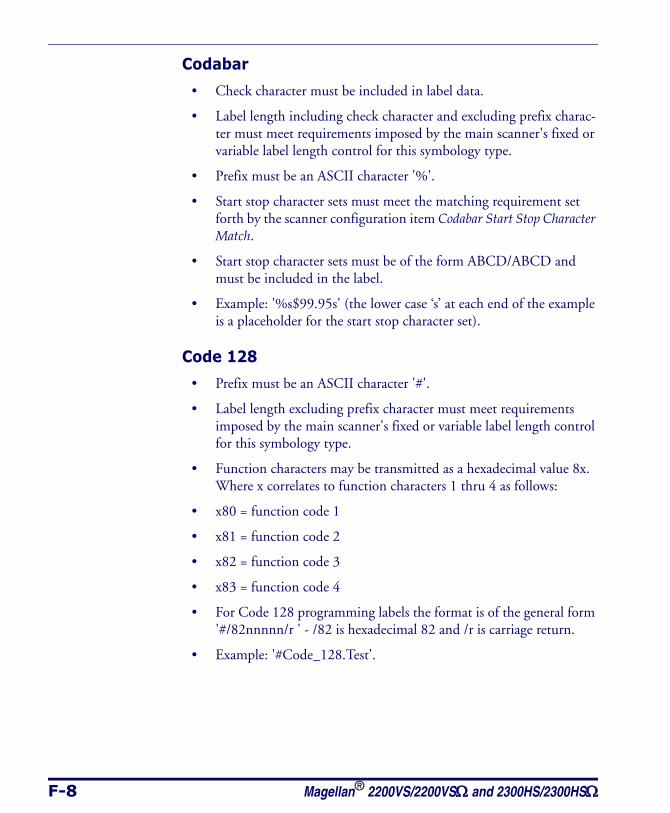
F-8 Magellan® 2200VS/2200VSΩ and 2300HS/2300HSΩ
Codabar
• Check character must be included in label data.
• Label length including check character and excluding prefix charac-ter must meet requirements imposed by the main scanner's fixed or variable label length control for this symbology type.
• Prefix must be an ASCII character '%'.
• Start stop character sets must meet the matching requirement set forth by the scanner configuration item Codabar Start Stop Character Match.
• Start stop character sets must be of the form ABCD/ABCD and must be included in the label.
• Example: '%s$99.95s' (the lower case ‘s’ at each end of the example is a placeholder for the start stop character set).
Code 128
• Prefix must be an ASCII character '#'.
• Label length excluding prefix character must meet requirements imposed by the main scanner's fixed or variable label length control for this symbology type.
• Function characters may be transmitted as a hexadecimal value 8x. Where x correlates to function characters 1 thru 4 as follows:
• x80 = function code 1
• x81 = function code 2
• x82 = function code 3
• x83 = function code 4
• For Code 128 programming labels the format is of the general form '#/82nnnnn/r ' - /82 is hexadecimal 82 and /r is carriage return.
• Example: '#Code_128.Test'.
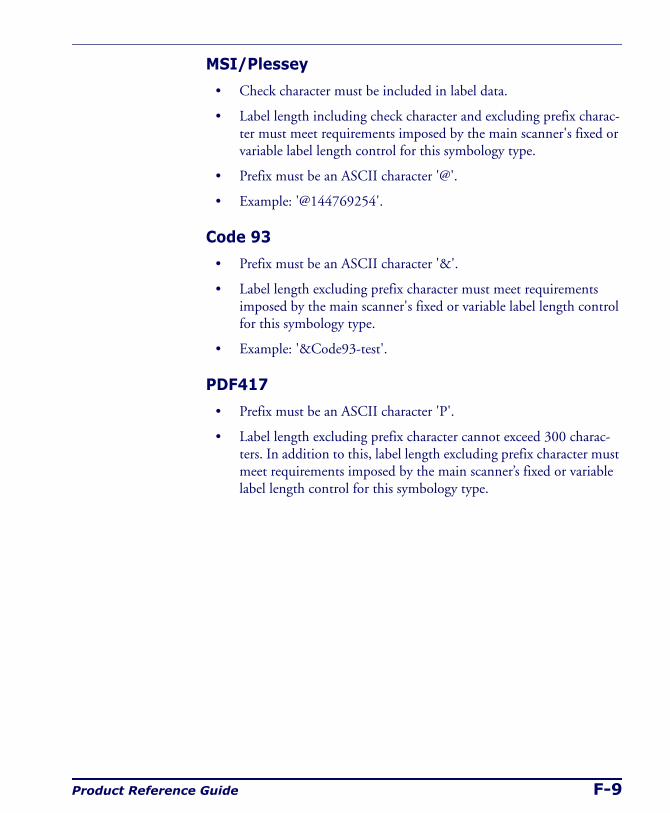
Product Reference Guide F-9
MSI/Plessey
• Check character must be included in label data.
• Label length including check character and excluding prefix charac-ter must meet requirements imposed by the main scanner's fixed or variable label length control for this symbology type.
• Prefix must be an ASCII character '@'.
• Example: '@144769254'.
Code 93
• Prefix must be an ASCII character '&'.
• Label length excluding prefix character must meet requirements imposed by the main scanner's fixed or variable label length control for this symbology type.
• Example: '&Code93-test'.
PDF417
• Prefix must be an ASCII character 'P'.
• Label length excluding prefix character cannot exceed 300 charac-ters. In addition to this, label length excluding prefix character must meet requirements imposed by the main scanner’s fixed or variable label length control for this symbology type.
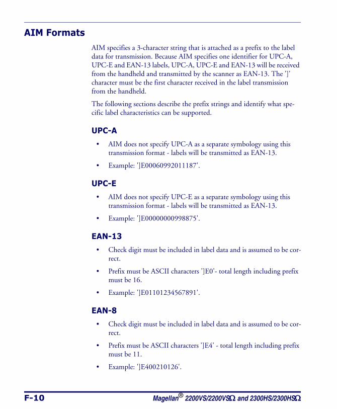
F-10 Magellan® 2200VS/2200VSΩ and 2300HS/2300HSΩ
AIM FormatsAIM specifies a 3-character string that is attached as a prefix to the label data for transmission. Because AIM specifies one identifier for UPC-A, UPC-E and EAN-13 labels, UPC-A, UPC-E and EAN-13 will be received from the handheld and transmitted by the scanner as EAN-13. The ']' character must be the first character received in the label transmission from the handheld.
The following sections describe the prefix strings and identify what spe-cific label characteristics can be supported.
UPC-A
• AIM does not specify UPC-A as a separate symbology using this transmission format - labels will be transmitted as EAN-13.
• Example: ']E00060992011187'.
UPC-E
• AIM does not specify UPC-E as a separate symbology using this transmission format - labels will be transmitted as EAN-13.
• Example: ']E00000000998875'.
EAN-13
• Check digit must be included in label data and is assumed to be cor-rect.
• Prefix must be ASCII characters ']E0'- total length including prefix must be 16.
• Example: ']E01101234567891'.
EAN-8
• Check digit must be included in label data and is assumed to be cor-rect.
• Prefix must be ASCII characters ']E4' - total length including prefix must be 11.
• Example: ']E400210126'.
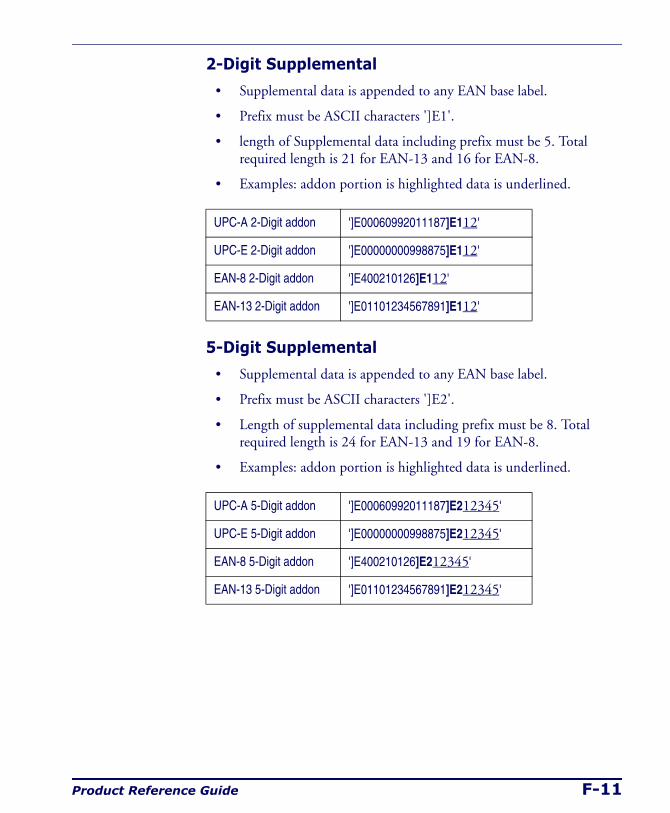
Product Reference Guide F-11
2-Digit Supplemental
• Supplemental data is appended to any EAN base label.
• Prefix must be ASCII characters ']E1'.
• length of Supplemental data including prefix must be 5. Total required length is 21 for EAN-13 and 16 for EAN-8.
• Examples: addon portion is highlighted data is underlined.
5-Digit Supplemental
• Supplemental data is appended to any EAN base label.
• Prefix must be ASCII characters ']E2'.
• Length of supplemental data including prefix must be 8. Total required length is 24 for EAN-13 and 19 for EAN-8.
• Examples: addon portion is highlighted data is underlined.
UPC-A 2-Digit addon ']E00060992011187]E112'
UPC-E 2-Digit addon ']E00000000998875]E112'
EAN-8 2-Digit addon ']E400210126]E112'
EAN-13 2-Digit addon ']E01101234567891]E112'
UPC-A 5-Digit addon ']E00060992011187]E212345'
UPC-E 5-Digit addon ']E00000000998875]E212345'
EAN-8 5-Digit addon ']E400210126]E212345'
EAN-13 5-Digit addon ']E01101234567891]E212345'
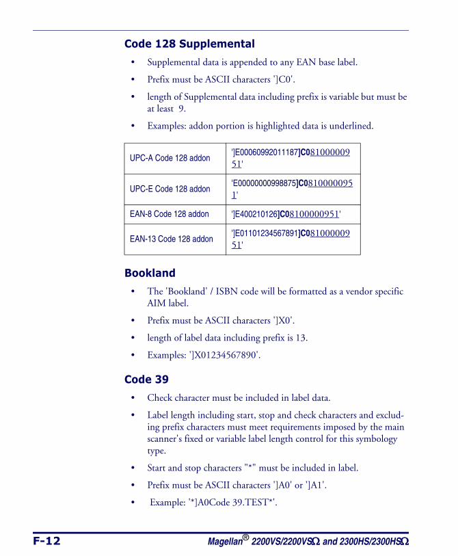
F-12 Magellan® 2200VS/2200VSΩ and 2300HS/2300HSΩ
Code 128 Supplemental
• Supplemental data is appended to any EAN base label.
• Prefix must be ASCII characters ']C0'.
• length of Supplemental data including prefix is variable but must be at least 9.
• Examples: addon portion is highlighted data is underlined.
Bookland
• The 'Bookland' / ISBN code will be formatted as a vendor specific AIM label.
• Prefix must be ASCII characters ']X0'.
• length of label data including prefix is 13.
• Examples: ']X01234567890'.
Code 39
• Check character must be included in label data.
• Label length including start, stop and check characters and exclud-ing prefix characters must meet requirements imposed by the main scanner's fixed or variable label length control for this symbology type.
• Start and stop characters "*" must be included in label.
• Prefix must be ASCII characters ']A0' or ']A1'.
• Example: '*]A0Code 39.TEST*'.
UPC-A Code 128 addon']E00060992011187]C08100000951'
UPC-E Code 128 addon'E00000000998875]C08100000951'
EAN-8 Code 128 addon ']E400210126]C08100000951'
EAN-13 Code 128 addon']E01101234567891]C08100000951'
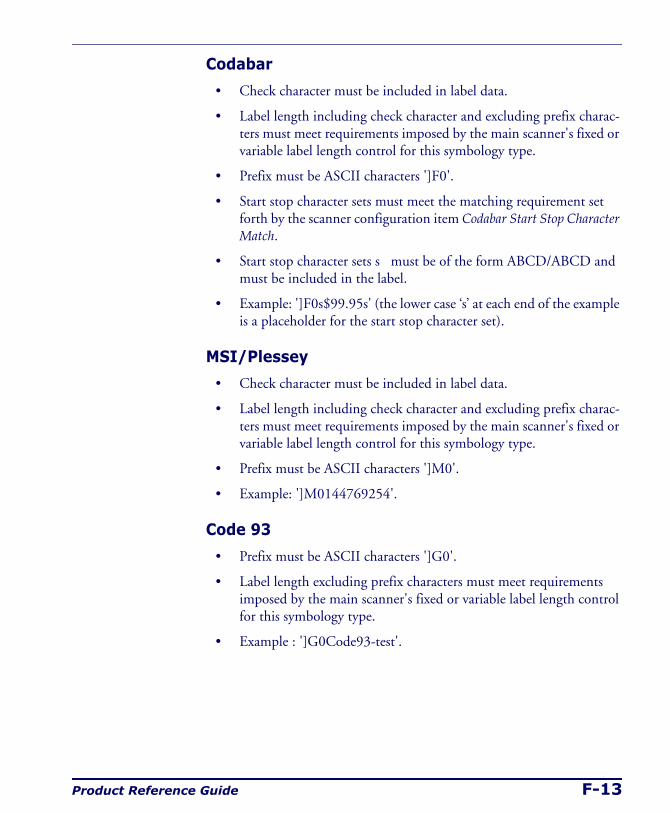
Product Reference Guide F-13
Codabar
• Check character must be included in label data.
• Label length including check character and excluding prefix charac-ters must meet requirements imposed by the main scanner's fixed or variable label length control for this symbology type.
• Prefix must be ASCII characters ']F0'.
• Start stop character sets must meet the matching requirement set forth by the scanner configuration item Codabar Start Stop Character Match.
• Start stop character sets s must be of the form ABCD/ABCD and must be included in the label.
• Example: ']F0s$99.95s' (the lower case ‘s’ at each end of the example is a placeholder for the start stop character set).
MSI/Plessey
• Check character must be included in label data.
• Label length including check character and excluding prefix charac-ters must meet requirements imposed by the main scanner's fixed or variable label length control for this symbology type.
• Prefix must be ASCII characters ']M0'.
• Example: ']M0144769254'.
Code 93
• Prefix must be ASCII characters ']G0'.
• Label length excluding prefix characters must meet requirements imposed by the main scanner's fixed or variable label length control for this symbology type.
• Example : ']G0Code93-test'.
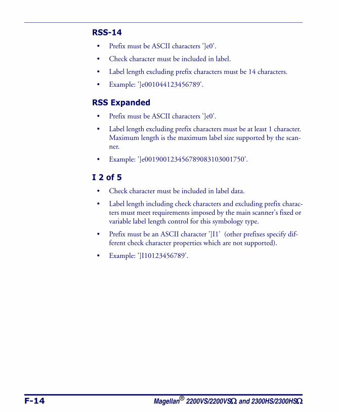
F-14 Magellan® 2200VS/2200VSΩ and 2300HS/2300HSΩ
RSS-14
• Prefix must be ASCII characters ']e0'.
• Check character must be included in label.
• Label length excluding prefix characters must be 14 characters.
• Example: ']e001044123456789'.
RSS Expanded
• Prefix must be ASCII characters ']e0'.
• Label length excluding prefix characters must be at least 1 character. Maximum length is the maximum label size supported by the scan-ner.
• Example: ']e001900123456789083103001750'.
I 2 of 5
• Check character must be included in label data.
• Label length including check characters and excluding prefix charac-ters must meet requirements imposed by the main scanner's fixed or variable label length control for this symbology type.
• Prefix must be an ASCII character ']I1' (other prefixes specify dif-ferent check character properties which are not supported).
• Example: ']I10123456789'.
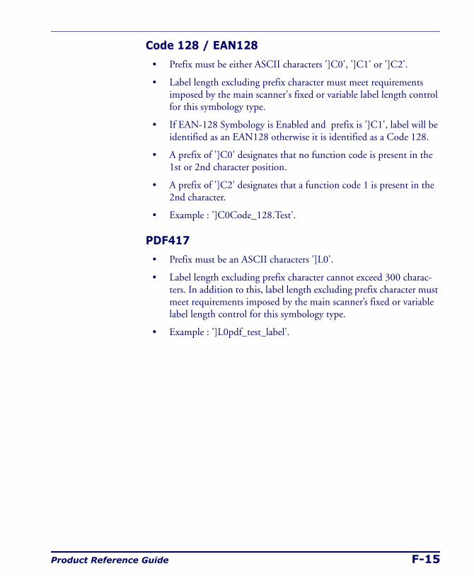
Product Reference Guide F-15
Code 128 / EAN128
• Prefix must be either ASCII characters ']C0', ']C1' or ']C2'.
• Label length excluding prefix character must meet requirements imposed by the main scanner's fixed or variable label length control for this symbology type.
• If EAN-128 Symbology is Enabled and prefix is ']C1', label will be identified as an EAN128 otherwise it is identified as a Code 128.
• A prefix of ']C0' designates that no function code is present in the 1st or 2nd character position.
• A prefix of ']C2' designates that a function code 1 is present in the 2nd character.
• Example : ']C0Code_128.Test'.
PDF417
• Prefix must be an ASCII characters ']L0'.
• Label length excluding prefix character cannot exceed 300 charac-ters. In addition to this, label length excluding prefix character must meet requirements imposed by the main scanner’s fixed or variable label length control for this symbology type.
• Example : ']L0pdf_test_label'.

F-16 Magellan® 2200VS/2200VSΩ and 2300HS/2300HSΩ
NOTES
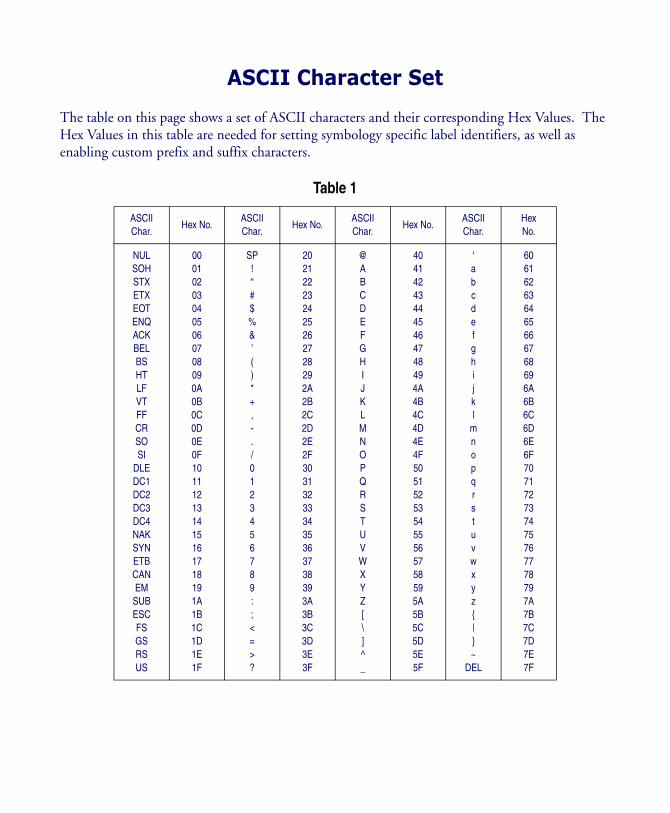
ASCII Character Set
The table on this page shows a set of ASCII characters and their corresponding Hex Values. The Hex Values in this table are needed for setting symbology specific label identifiers, as well as enabling custom prefix and suffix characters.
Table 1
ASCII Char.
Hex No.ASCII Char.
Hex No.ASCII Char.
Hex No.ASCII Char.
HexNo.
NULSOHSTXETXEOTENQACKBELBSHTLFVTFFCRSOSI
DLEDC1DC2DC3DC4NAKSYNETBCANEM
SUBESCFSGSRSUS
000102030405060708090A0B0C0D0E0F101112131415161718191A1B1C1D1E1F
SP!“#$%&’()*+,-./0123456789:;<=>?
202122232425262728292A2B2C2D2E2F303132333435363738393A3B3C3D3E3F
@ABCDEFGHIJKLMNOPQRSTUVWXYZ[\]^_
404142434445464748494A4B4C4D4E4F505152535455565758595A5B5C5D5E5F
‘abcdefghijkl
mnopqrstuvwxyz{|}~
DEL
606162636465666768696A6B6C6D6E6F707172737475767778797A7B7C7D7E7F
Asia PacificPSC Hong KongHong KongTelephone: [852]-2-584-6210Fax: [852]-2-521-0291
AustraliaPSC Asia Pacific Pty Ltd.North Ryde, AustraliaTelephone: [61] 0 (2) 9878 8999Fax: [61] 0 (2) 9878 8688
FrancePSC S.A.R.L.LES ULIS Cedex, FranceTelephone: [33].01.64.86.71.00Fax: [33].01.64 46.72.44
GermanyPSC GmbHDarmstadt, GermanyTelephone: 49 (0) 61 51/93 58-0Fax: 49 (0) 61 51/93 58 58
ItalyPSC S.p.A.Vimercate (MI), ItalyTelephone: [39] (0) 39/62903.1Fax: [39] (0) 39/6859496
JapanPSC Japan K.K.Shinagawa-ku, Tokyo, JapanTelephone: 81 (0)3 3491 6761Fax: 81 (0)3 3491 6656
Latin AmericaPSC S.A., INC.Miami, Florida, USATelephone: (305) 591-3222Fax: (305) 591-3007
United KingdomPSC Bar Code Ltd.Watford, EnglandTelephone: 44 (0) 1923 809500Fax: 44 (0) 1923 809 505
PSC Inc.959 Terry StreetEugene, OR 97402Telephone: (541) 683-5700Fax: (541) 345-7140
www.psc.com
©2002 - 2006 PSC INC. R44-2365 (Rev. N) 8/06